

Page 1

HP A-F5000 Firewall
Installation Guide
Part number: 5998-1413
Document version: 6PW100-20110909
Page 2

Legal and notice information
© Copyright 2011 Hewlett-Packard Development Company, L.P.
No part of this documentation may be reproduced or transmitted in any form or by any means without
prior written consent of Hewlett-Packard Development Company, L.P.
The information contained herein is subject to change without notice.
HEWLETT-PACKARD COMPANY MAKES NO WARRANTY OF ANY KIND WITH REGARD TO THIS
MATERIAL, INCLUDING, BUT NOT LIMITED TO, THE IMPLIED WARRANTIES OF MERCHANTABILITY
AND FITNESS FOR A PARTICULAR PURPOSE. Hewlett-Packard shall not be liable for errors contained
herein or for incidental or consequential damages in connection with the furnishing, performance, or use
of this material.
The only warranties for HP products and services are set forth in the express warranty statements
accompanying such products and services. Nothing herein should be construed as constituting an
additional warranty. HP shall not be liable for technical or editorial errors or omissions contained herein.
Page 3

i
Contents
Product overview·························································································································································· 1
A-F5000 physical architecture·········································································································································1
Main processing unit (NSQ1MPUA0) ····························································································································2
Interface modules ······························································································································································2
NSQ1GT8C40·························································································································································2
NSQ1GT8P40··························································································································································3
NSQ1XP20·······························································································································································3
Power supplies···································································································································································3
AC-input power supply ············································································································································4
DC-input power supply ············································································································································4
Fan trays·············································································································································································5
Preparing for installation ············································································································································· 6
Safety recommendations ··················································································································································6
Safety symbols ··························································································································································6
General safety recommendations ···························································································································6
Safety with electricity ···············································································································································6
Safety with laser ·······················································································································································6
Safety with firewall moving ·····································································································································7
Examining the installation site ·········································································································································7
Temperature and humidity·······································································································································7
Altitude ······································································································································································8
Cleanness··································································································································································8
Cooling system ·························································································································································8
ESD prevention ·························································································································································9
EMI·········································································································································································· 10
Lightning protection··············································································································································· 10
Rack-mounting························································································································································ 11
Installation tools······························································································································································ 11
Accessories supplied by the firewall ···························································································································· 11
Checklist before installation ·········································································································································· 12
Installing the firewall··················································································································································14
Installation flow ······························································································································································15
Check before installation··············································································································································· 15
Installing the firewall in a 19-inch rack························································································································ 15
Installing cage nuts to the rack ····························································································································15
Installing the cable management brackets·········································································································· 16
Installing the mounting brackets to the firewall ·································································································· 17
Installing the firewall to the rack·························································································································· 18
Grounding the firewall ·················································································································································· 18
Installing an MPU ··························································································································································· 19
Installing an interface module······································································································································· 20
Installing a fan tray ························································································································································ 21
Installing a CF card························································································································································ 22
Installing an air filter (optional)····································································································································· 23
Installing a power supply ·············································································································································· 24
Connecting a power cord ············································································································································· 25
Connecting an AC power cord ··························································································································· 25
Connecting a DC power cord······························································································································ 26
Page 4

ii
Connecting Ethernet cables··········································································································································· 26
Connecting a copper Ethernet cable··················································································································· 26
Connecting an optical fiber ································································································································· 27
Logging in to the firewall and configuring basic settings ·······················································································30
Logging in to the firewall through the console port···································································································· 30
Connecting the firewall to a configuration terminal ·························································································· 30
Setting terminal parameters·································································································································· 31
Powering on the firewall ···············································································································································34
Checking before power-on··································································································································· 34
Powering on the firewall······································································································································· 34
Checking after power-on ······································································································································ 34
Logging in to the firewall through Telnet ····················································································································· 34
Logging to the firewall through a web browser·········································································································· 35
Performing basic settings for the firewall····················································································································· 36
Launching the basic configuration wizard·········································································································· 36
Configuring the system name and user password····························································································· 36
Configuring service management························································································································ 37
Configuring the IP address for an interface········································································································ 39
Configuring NAT··················································································································································· 40
Completing the configuration wizard ·················································································································41
Hardware management and maintenance ··············································································································43
Displaying hardware information of the firewall ········································································································ 43
Displaying the software and hardware version information of the firewall···················································· 43
Displaying the operational statistics of the firewall ···························································································44
Displaying the detailed information about a module ························································································ 44
Displaying the electrical label information of a module ··················································································· 45
Displaying the CPU usage of a module ·············································································································· 46
Displaying the memory usage of the MPU ········································································································· 46
Displaying the CF card information ····················································································································46
Displaying the operational status of the fan ······································································································· 47
Displaying the operational status of power supplies························································································· 47
Solving system faults ······················································································································································ 47
Solving system faults ············································································································································· 47
Viewing the system fault solving method ············································································································ 48
Saving the current configuration of the firewall·········································································································· 48
Rebooting a module or the firewall······························································································································ 49
Replacement procedures ···········································································································································50
Safety recommendations ··············································································································································· 50
Replacing a power supply ············································································································································ 50
Replacing an MPU ························································································································································· 51
Replacing an interface module····································································································································· 52
Replacing a transceiver module ··································································································································· 52
Replacing a CF card······················································································································································ 53
Replacing a fan tray ······················································································································································ 54
Replacing an air filter ···················································································································································· 55
Troubleshooting··························································································································································57
MPU failures ··································································································································································· 57
RUN LED is off ······················································································································································· 57
RUN LED fast flashes············································································································································· 57
ALM LED is steady on or flashes·························································································································· 58
Interface module failures ··············································································································································· 58
RUN LED is off ······················································································································································· 58
Page 5

iii
RUN LED fast flashes············································································································································· 58
Power supply failures····················································································································································· 58
Power LED is off····················································································································································· 58
Red power LED is on············································································································································· 59
Fan failures ····································································································································································· 59
Fan tray is absent ·················································································································································· 59
ALM LED is red ······················································································································································ 59
Configuration system problems ···································································································································· 60
No terminal display ·············································································································································· 60
Garbled terminal display······································································································································ 60
Using the AUX port as the backup console port········································································································· 60
Password loss ································································································································································· 61
User password loss ···············································································································································61
Super password loss ············································································································································· 62
Cooling system failure ··················································································································································· 62
Host software file missing errors··································································································································· 63
Appendix A Technical specifications························································································································65
Dimensions and weight ················································································································································· 65
Power consumption range············································································································································· 65
AC power supply ··························································································································································· 65
DC power supply ··························································································································································· 65
Fan tray ··········································································································································································· 66
MPU (NSQ1MPUA0)····················································································································································· 66
Technical specifications ········································································································································ 66
Components ··························································································································································· 67
Interface modules ··························································································································································· 69
NSQ1GT8C40······················································································································································ 69
NSQ1XP20···························································································································································· 69
NSQ1GT8P40······················································································································································· 69
Appendix B LEDs························································································································································70
MPU LEDs········································································································································································ 70
Interface module LEDs···················································································································································· 71
NSQ1GT8C40/NSQ1GT8P40·························································································································· 71
NSQ1XP20···························································································································································· 72
Power supply LEDs ························································································································································· 73
Fan tray LEDs ·································································································································································· 74
Appendix C Cables ···················································································································································75
Ethernet twisted pair cable············································································································································ 75
Introduction ···························································································································································· 75
Making an Ethernet twisted pair cable ··············································································································· 78
Optical fiber ··································································································································································· 79
Appendix D AC power cables used in different countries or regions··································································81
10A AC power cables used in different countries or regions··················································································· 81
16A AC power cables used in different countries or regions··················································································· 84
Support and other resources ·····································································································································87
Contacting HP ································································································································································ 87
Subscription service ·············································································································································· 87
Related information························································································································································ 87
Documents······························································································································································ 87
Websites································································································································································· 87
Conventions ···································································································································································· 88
Page 6

iv
Index ···········································································································································································90
Page 7
1
Product overview
This chapter includes these sections:
• A-F5000 physical architecture
• Main processing unit (NSQ1MPUA0)
• Interface modules
• Power supplies
• Fan trays
A-F5000 physical architecture
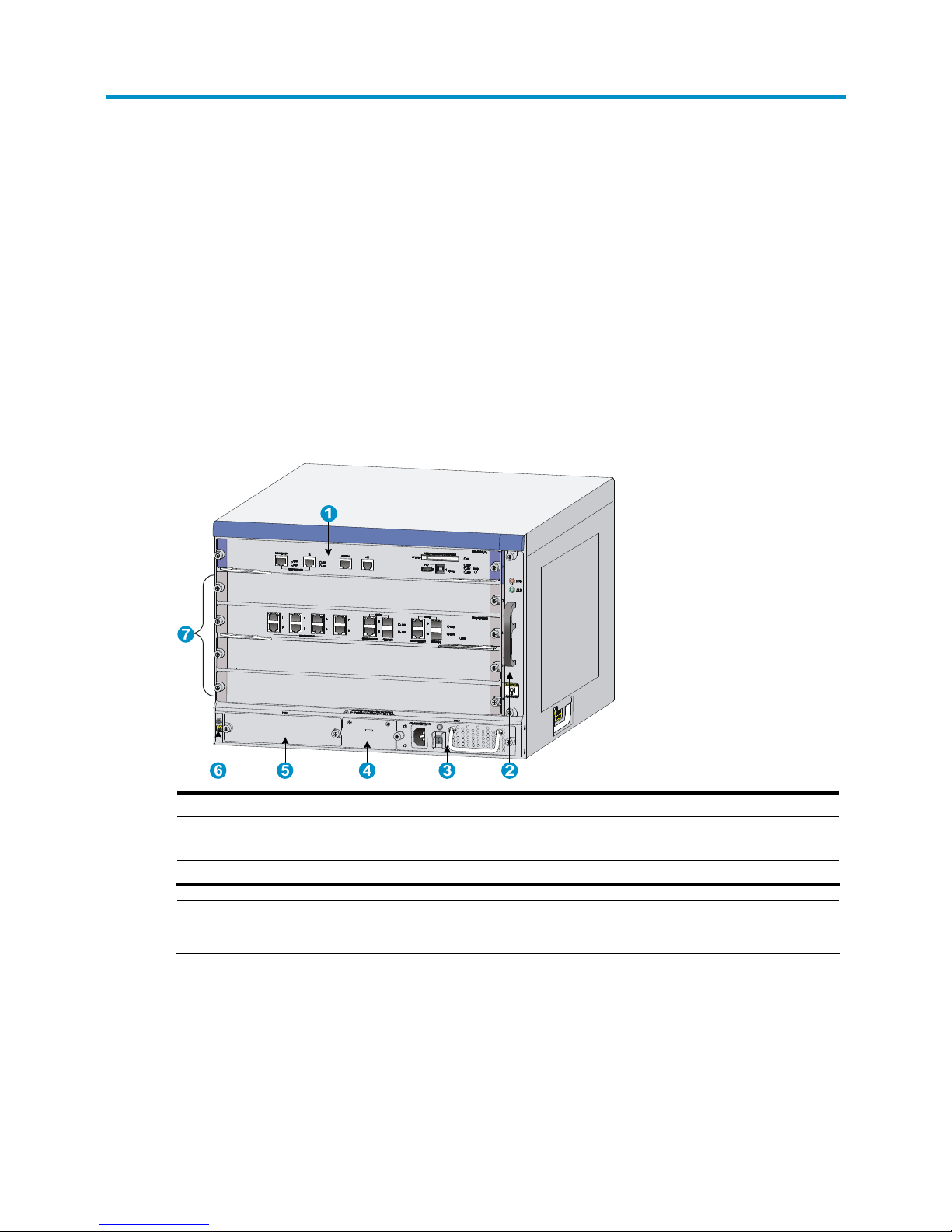
Figure 1 Front view
(1) MPU slot (slot 0) (2) Fan tray
(3) Power supply slot (PWR1) (AC power supply in this figure) (4) PoE module slot (reserved)
(5) Power supply slot (PWR2) (6) ESD-preventive wrist strap slot and mark
(7) Interface module slots (slots 1 through 4)
NOTE:
No PoE modules are available for the firewall.
Page 8
2
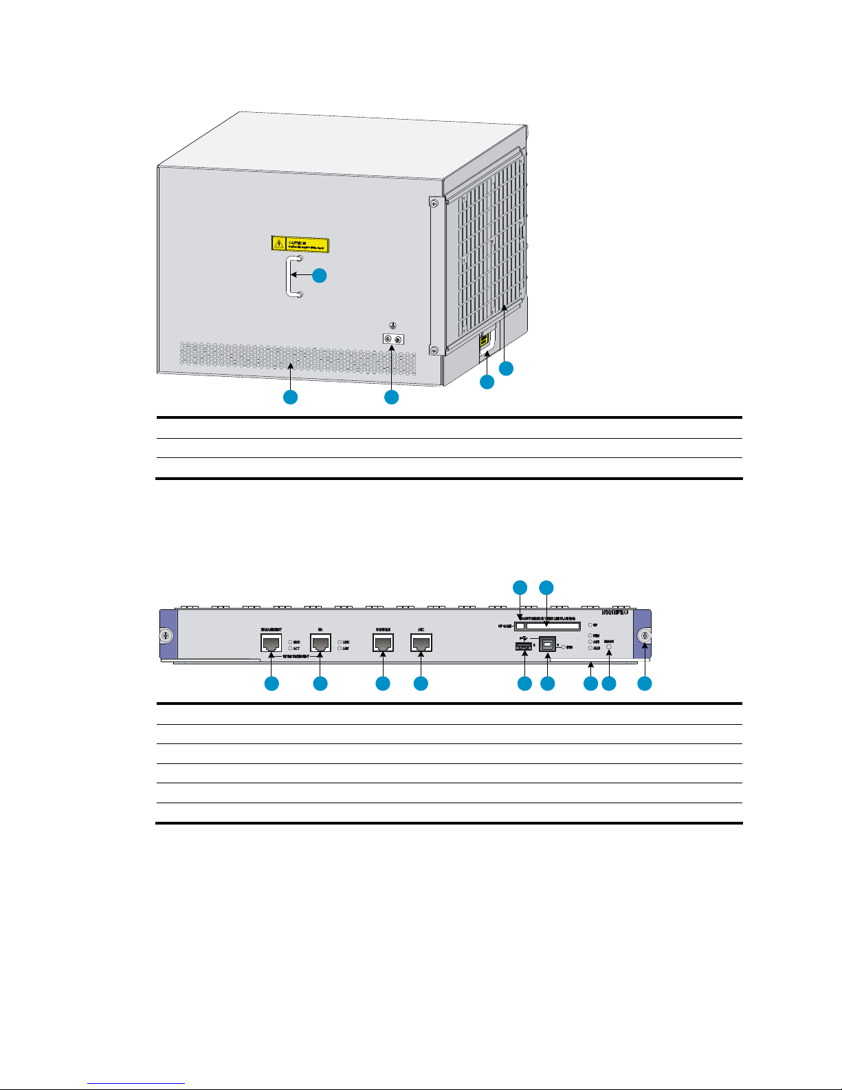
Figure 2 Rear view
1
2
3
45
(1) Rear cover handle (do not use this handle to lift the chassis) (2) Air filter (optional)
(3) Chassis handle (4) Grounding terminal and sign
(5) Air vents
Main processing unit (NSQ1MPUA0)
Figure 3 NSQ1MPUA0 front panel
1 2
3456789
1011
(1) CF card button (2) CF card slot
(3) Captive screw (4) Reset button (RESET)
(5) Ejector lever (6) Device-mode USB port 1 (1)
(7) Host-mode USB port 0 (0) (8) AUX port (AUX)
(9) Console port (CONSOLE) (10) HA port (HA)
(11) Management Ethernet port (MANAGEMENT)
Interface modules
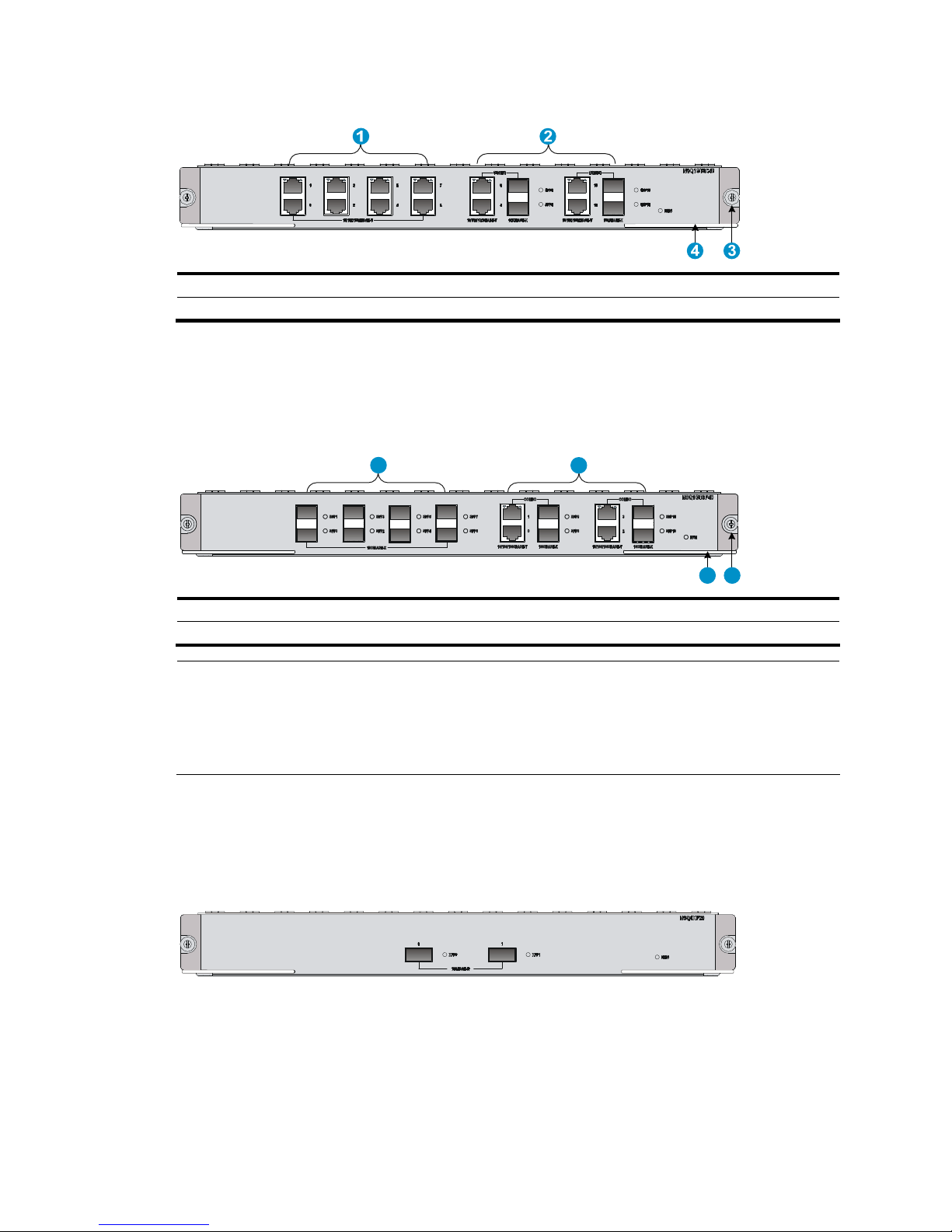
NSQ1GT8C40
The NSQ1GT8C40 provides eight copper ports and four combo interfaces.
Page 9
3
Figure 4 NSQ1GT8C40 front panel
(1) Copper ports (GE0 through GE7) (2) Combo interfaces (GE8 through GE11)
(3) Captive screw (4) Ejector lever
NSQ1GT8P40
The NSQ1GT8P40 provides eight fiber ports and four combo interfaces.
Figure 5 NSQ1GT8P40 front panel
34
1 2
(1) Fiber ports (GE0 through GE7) (2) Combo interfaces (GE8 through GE11)
(3) Captive screw (4) Ejector lever
NOTE:
A combo interface comprises a copper port and an SFP port. By default, the copper port of a combo
interface is enabled. The two ports cannot work simultaneously. When you enable either port, the other
port is automatically disabled. To activate the copper combo port or fiber combo port, use the combo
enable { copper | fiber } command in interface view.
NSQ1XP20
The NSQ1XP20 provides two XFP ports and supports the LAN PHY mode only.
Figure 6 NSQ1XP20 front panel
Power supplies
Th e HP A-F5000 can be DC-powered or AC-powered. You can i nstall t wo power supplies i n yo ur firewal l,
and they must be the same model.
Page 10
4
The A-F5000 firewall uses hot swappable power supplies. You can install one power supply, or for
redundancy, two power supplies for your firewall.
AC-input power supply
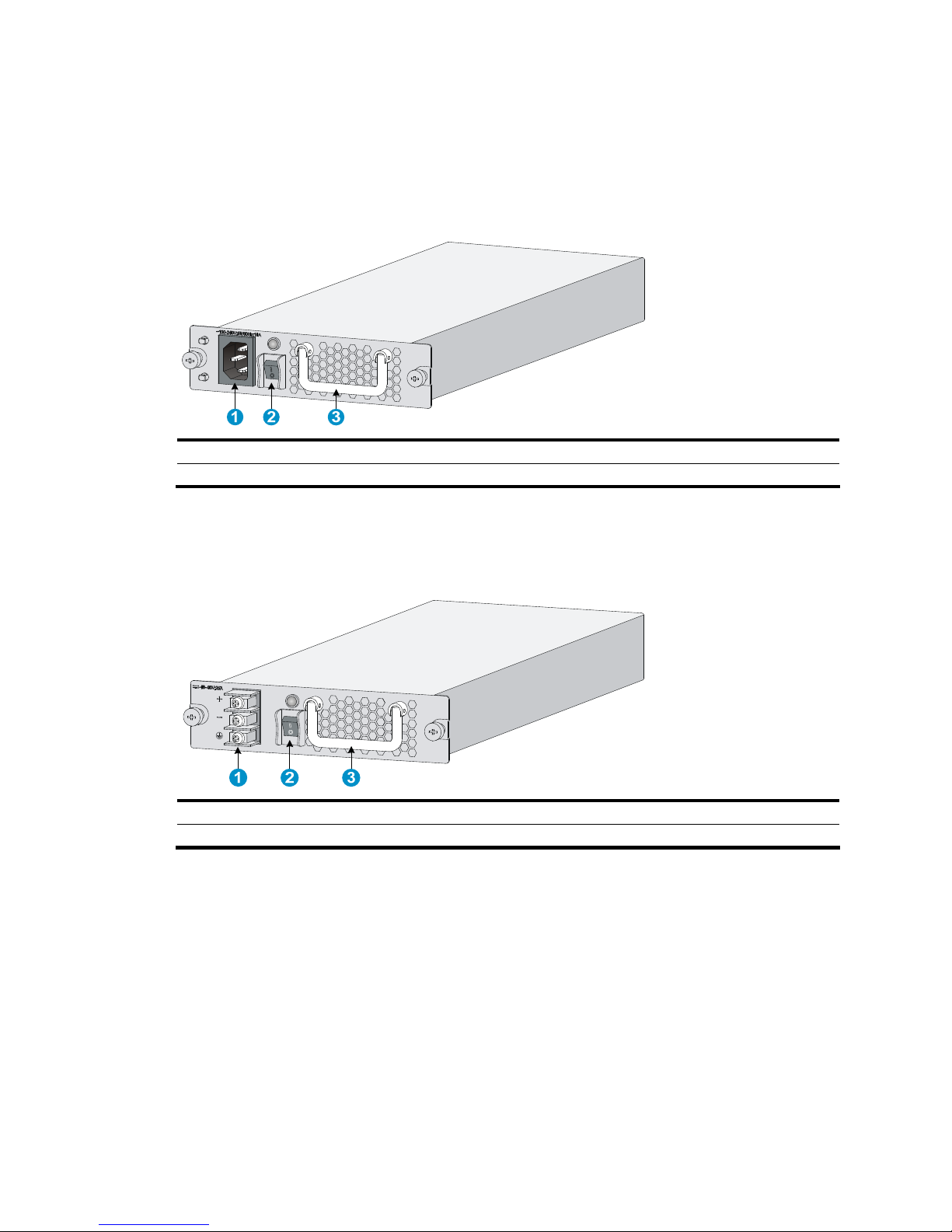
Figure 7 AC-input power supply front view
(1) AC-input power receptacle (2) Power switch
(3) Handle
DC-input power supply
Figure 8 DC-input power supply front view
(1) DC-input terminal block (2) Power switch
(3) Handle
Page 11

5
Fan trays
Figure 9 Fan tray
(1) Handle (2) Fans
Page 12

6
Preparing for installation
This chapter includes these sections:
• Safety recommendations
• Examining the installation site
• Installation tools
• Accessories supplied by the firewall
• Checklist before installation
Safety recommendations
Safety symbols
When reading this document, note the following symbols:
WARNING means an alert that calls attention to important information that if not understood or
followed can result in personal injury.
CAUTION means an alert that calls attention to important information that if not understood or
followed can result in data loss, data corruption, or damage to hardware or software.
General safety recommendations
• Keep the chassis and installation tools away from walk areas.
• Make sure that the ground is dry and flat and anti-slip measures are in place.
• Unplug all the external cables (including power cords) before moving the chassis.
Safety with electricity
• Locate the emergency power-off switch in the room before installation. Shut the power off at once in
case accident occurs.
• Make sure that the firewall has been correctly grounded.
• Do not open or close the chassis cover when the firewall is powered on.
• Use an uninterrupted power supply (UPS).
• If there are two power inputs, disconnect the two power inputs to power off the firewall.
• Do not work alone when the firewall has power.
• Always check that the power has been disconnected.
Safety with laser
• Do not stare into the optical port or fiber connector because the laser light emitted from the optical
fiber may hurt your eyes.
• Install a dust plug on the transceiver module to avoid damage to the transceiver module.
Page 13

7
Safety with firewall moving
When moving an A-F5000 firewall, note the following guidelines:
• When moving the firewall, hold the handles at both sides of the chassis.
• Use at least two persons to move the firewall.
• Move the firewall carefully.
CAUTION:
Do not hold the handle of the fan tray or power supply, the handle of the rear cover of the chassis, or the
air vents of chassis. Any attempt to carry the firewall with these parts may cause equipment damage or
even bodily injury.
Examining the installation site
The A-F5000 firewall can only be used indoors. To ensure that the firewall works properly and to prolong
its service lifetime, the installation site must meet the following requirements:
• Temperature and humidity
• Altitude
• Cleanness
• Cooling system
• ESD prevention
• EMI
• Lightning protection
• Rack-mounting
Temperature and humidity
You must maintain a proper temperature and humidity in the equipment room. Long-term high humidity
may lead to bad insulation, electricity leakage, mechanical property changes, and metal corrosion.
However, if the humidity is too low, captive screws may become loose as the result of contraction of
insulation washers and static electricity may be produced in a dry environment to jeopardize the circuits
on the device. A high temperature is the most undesirable condition, because it accelerates the aging of
insulation materials and significantly lowers reliability and service life of the firewall.
Table 1 Temperature requirements
Item Temperature
Operating temperature 0°C to 45°C (32°F to 113°F)
Storage temperature –40°C to 70°C(–40°F to 158°F)
Table 2 Humidity requirements
Item Humidity
Operating humidity 10% to 95%
Storage humidity 5% to 95%
Page 14

8
Altitude
Table 3 Altitude requirements
Item Altitude
Operating altitude –60 m (–196.85 ft) to 4 km (2.49 miles)
Storage altitude –60 m (–196.85 ft) to 4.5km(2.8 miles)
Cleanness
Dust buildup on the chassis may result in electrostatic adsorption, which causes poor contact of metal
components and contact points, especially when indoor humidity is low. In the worst case, electrostatic
adsorption can cause communication failure.
Table 4 Dust concentration limit in the equipment room
Substance Concentration limit (particles/cu m)
Dust particles
≤ 3 x 10⁴
(No visible dust on desk in three days)
NOTE:
Dust particle diameter ≥ 5 μm
The equipment room must also meet strict limits on salts, acids, and sulfides to eliminate corrosion and
premature aging of components, as shown in Table 5.
Table 5 Harmful gas li
mits in an equipment room
Gas Max. (mg/m
3
)
SO2 0.2
H2S 0.006
NH
3
0.05
Cl
2
0.01
Cooling system
The A-F5000 firewall adopts left to right airflow for heat dissipation.
Page 15

9
Figure 10 A-F5000 airflow
• Make sure there is enough space (greater than 10 cm (3.94 in)) around the air intake and outlet
vents on the firewall for good ventilation.
• Make sure the installation site has a good cooling system.
ESD prevention
To prevent electrostatic discharge (ESD), note the following guidelines:
• Make sure that the firewall and the floor are well grounded.
• Take dust-proof measures for the equipment room.
• Maintain the humidity and temperature at a proper level.
• Always wear an ESD-preventive wrist strap when touching a circuit board or transceiver module.
• Place the removed CF card or interface module on an antistatic workbench, with the face upward,
or put it into an antistatic bag.
• Touch only the edges, instead of electronic components when observing or moving a removed CF
card or interface module.
To use the ESD-preventive wrist strap, perform the following steps:
1. Wear the wrist strap on your wrist.
2. Lock the wrist strap tight around your wrist to keep good contact with the skin.
3. Insert the ESD-preventive wrist strap into the specially designed hole on the firewall chassis.
4. Make sure that the firewall chassis is well grounded.
Page 16

10
Figure 11 Use an ESD-preventive wrist strap
1
2
3
(1) ESD-preventive wrist strap (2) Lock
(3) leash
CAUTION:
Check the resistance of the ESD-preventive wrist strap for safety. The resistance readin
g
should be in the
range of 1 to 10 megohm (Mohm) between human body and the ground.
EMI
All electromagnetic interference (EMI) sources, from outside or inside of the firewall and application
system, adversely affect the firewall in a conduction pattern of capacitance coupling, inductance
coupling, electromagnetic wave radiation, or common impedance (including grounding system)
coupling. To prevent EMI, note the following guidelines:
• Take measures against interference from the power grid.
• Do not use the firewall together with the grounding equipment or light-prevention equipment of
power equipment, and keep the firewall far away from them.
• Keep the firewall far away from high-power radio launchers, radars, and equipment with high
frequency or high current.
NOTE:
Use electromagnetic shielding when necessary.
Lightning protection
To protect the firewall from lightning better, do as follows:
• Make sure the grounding cable of the chassis is well grounded.
Page 17

11
• Make sure the grounding terminal of the AC power receptacle is well grounded.
• Install a lightning arrester at the input end of the power supply to enhance the lightning protection
capability of the power supply.
Rack-mounting
Before mounting the firewall in a rack, adhere to the following requirements:
• Install the firewall to a rack that has rack shelves.
• The rack is sturdy enough to support the firewall and its accessories.
• Make sure that the size of the rack is appropriate for the firewall, and that there is enough clearance
around the left and right sides of the firewall for heat dissipation.
• For heat dissipation and device maintenance, make sure the front and rear of the rack is at least 0.8
m (2.62 ft) away from walls or other devices, and that the headroom in the equipment room is no
less than 3 m (9.84 ft).
Installation tools
Flat-blade
screwdriver
Phillips screwdriver
Needle-nose pliers
Wire-stripping
pliers
Diagonal pliers
RJ45 crimping
pliers
Multimeter
Network cable
tester
Mark pen
NOTE:
No installation tool is provided with the firewall. Prepare them yourself.
Accessories supplied by the firewall
Console cable Grounding cable
ESD-preventive
wrist strap
Cable tie
Mounting
brackets
M6 screw Cage nut
Page 18

12
Checklist before installation
Table 6 Checklist before installation
Item Requirements Result
Ventilation
• There is a minimum clearance of 10 cm (3.94 in)
around the inlet and exhaust vents for heat
dissipation of the firewall chassis.
• A ventilation system is available at the installation
site.
Operating
temperature
0°C to 45°C (32°F to 113°F)
Operating
humidity
10% to 95%
Cleanness
• Dust concentration ≤ 3 × 10
4
particles/m³
• No dust on desk within three days
ESD prevention
• The equipment and floor are well grounded.
• The equipment room is dust-proof.
• The humidity and temperature are at a proper level,
respectively.
• Wear an ESD-preventive wrist strap and uniform
when touching a circuit board.
• Place the removed CF card or interface module on an
antistatic workbench, with the face upward, or put it
into an antistatic bag.
• Touch only the edges, instead of electronic
components when observing or moving a removed
CF card or interface module.
EMI prevention
• Take effective measures to protect the power system
from the power grid system.
• Separate the protection ground of the firewall from
the grounding device or lightning protection
grounding device as far as possible.
• Keep the firewall far away from radio stations, radar
and high-frequency devices working in high current.
• Use electromagnetic shielding when necessary.
Lightning
protection
• The grounding cable of the chassis is well grounded.
• The grounding terminal of the AC power receptacle
is well grounded.
Electricity safety
• Equip an uninterrupted power supply (UPS).
• In case of emergency du ring operation, switch off the
external power switch.
Installation site
Rack-mounting
requirements
• The rack is sturdy enough to support the weight of the
firewall and installation accessories.
• The size of the rack is appropriate for the firewall.
• The front and rear of the rack are at least 0.8 m
(31.50 in) away from walls or other devices.
Page 19

13
Item Requirements Result
Safety
precautions
• The firewall is far away from any moist area and heat source.
• The emergency power switch in the equipment room is located.
Tools
• Installation accessories supplied with the firewall
• User supplied tools
Reference
• Documents shipped with the firewall
• Online documents
Page 20

14
Installing the firewall
This chapter includes these sections:
• Installation flow
• Check before installation
• Installing the firewall in a 19-inch rack
• Grounding the firewall
• Installing an MPU
• Installing an interface module
• Installing a fan tray
• Installing a CF card
• Installing an air filter (optional)
• Installing a power supply
• Connecting a power cord
• Connecting Ethernet cables
IMPORTANT:
Keep the packages of your firewall and its accessories safely for future use.
Page 21
15
Installation flow
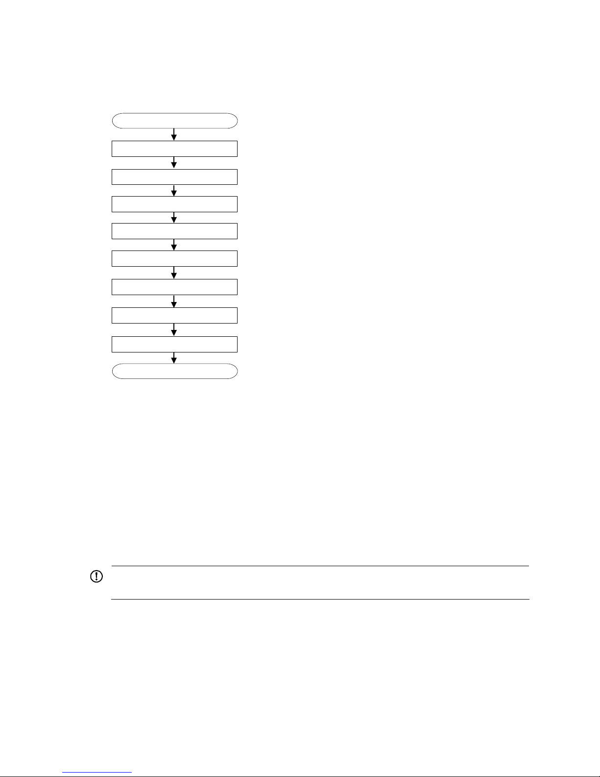
Figure 12 HP A-F5000 firewall installation flow
Start
Ground the firewall
Install an MPU/interface module
Connect Ethernet cables
Install the firewall to a 19 inch rack
End
Install a fan tray
Install a CF card
Connect a power cord
Install a power supply
Check before installation
Follow these steps to prepare for installing an HP A-F5000 firewall:
• Make sure that you h ave read “ Preparing for installation”
carefully and the installation site meets all
the requirements.
• Prepare a 19-inch rack.
• Make sure that the rack is sturdy and securely grounded and has enough space for mounting the
firewall.
• Make sure that there is no debris inside or around the rack.
• Move the firewall to a place near the rack.
IMPORTANT:
To mount multiple devices in the rack, mount the heavier equipment at a lower position.
Installing the firewall in a 19-inch rack
To install an A-F5000 to a rack, you need mounting brackets and rack shelves.
Installing cage nuts to the rack
Follow these steps to install cage nuts to the rack:
Page 22

16
1. Determine where to install the firewall in the rack, and then install a rack shelf to the rack.
2. As shown in Figure 13, mark the positions of cage nuts on the front rack posts by using a front
mounting bracket.
Figure 13 Mark the positions of the cage nuts
3. As shown in Figure 14, install the cage nuts to the marked positions on the rack posts.
Figure 14 Install cage nuts
Installing the cable management brackets
As shown in Figure 15, before installing a mounting bracket to the firewall, install the cable management
bracket to the left mounting bracket with screws.
Page 23

17
Figure 15 Install the cable management bracket
(1) Left mounting bracket (2) Cable management bracket
Installing the mounting brackets to the firewall
NOTE:
If you have ordered an air filter, install the air filter before installing the mounting brackets. For how to
install an air filter, see “Installing an air filter (optional).”
Before installing the firewall to a rack, install the front mounting brackets to the two sides of the firewall.
Figure 16 Install the front mounting brackets to the two sides of the firewall
Page 24
18
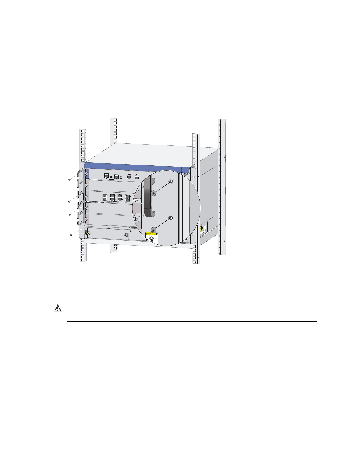
Installing the firewall to the rack
Follow these steps to install the firewall to the rack:
1. Put the firewall on the rack shelf, slide the firewall, and align the screw holes on the mounting
brackets with the cage nuts on the rack.
2. Fix the firewall horizontally by fastening the mounting brackets to the rack with appropriate pan
head screws. The specifications of pan head screws must satisfy the installation requirements, and
rustproof treatment has been made to their surfaces.
Figure 17 Fix the firewall to the rack
Grounding the firewall
WARNING!
Correctly connecting the firewall grounding cable is crucial to lightning protection and EMI protection.
Follow these steps to connect the grounding cable:
1. Remove the grounding screw from the rear panel of the firewall chassis.
2. Attach the grounding screw to the OT terminal of the grounding cable.
3. Use a screwdriver to fasten the grounding screw into the grounding screw hole.
4. Connect the other end of the grounding cable to the grounding strip of the rack.
Page 25

19
Figure 18 Connect the grounding cable to the grounding hole of firewall
NOTE:
To guarantee the grounding effect, use the grounding cable provided with the firewall to connect to the
grounding strip as long as possible.
Installing an MPU
NOTE:
• The A-F5000 supports only one MPU, which must be installed in slot 0.
• Typically the firewall does not provide a filler panel for slot 0 when it is shipped because you must install
an MPU to the slot for the firewall to operate.
Follow these steps to install an MPU:
1. Gently push the MPU along the slide rails into the slot and then push the ejector levers inward to
lock the MPU in position.
Page 26

20
Figure 19 Insert the MPU into slot
2. Fasten the captive screws on the MPU with a Phillips screwdriver.
3. After the firewall is powered on, the RUN LED flashes fast (at 8 Hz). It flashes slowly (at 1 Hz) after
the application is loaded. This means that the MPU runs properly. For the LED description, see the
chapter “Appendix B LEDs.”
Installing an interface module
NOTE:
• An interface module can only be installed in slot 1, 2, 3, or 4.
• You must install an MPU and at least one interface module for the firewall to operate properly.
• Typically the firewall does not provide a filler panel for one of the interface module slots when it is
shipped.
The procedures for installing interface modules are the same. The following uses an NSQ1GT8C40 as
an example.
Follow these steps to install an interface module:
1. Remove the filler panel (if any) from the slot you want to install an interface module: use a Phillips
screwdriver to loosen the captive screws on the filler panel until all spring pressure is released, and
then remove the filler panel.
2. Push the interface module along the guide rails into the slot until it touches the slot bottom, and then
push the ejector levers inward to lock the interface module in position.
Page 27

21
Figure 20 Insert an interface module
3. Fasten the captive screws on the interface module with a Phillips screwdriver.
4. After the firewall is powered on, the RUN LED flashes once and then flashes fast (at 8 Hz). It flashes
slowly (at 1 Hz) after the application is loaded. This means that the interface module runs properly.
For more information of the interface module LEDs, see the chapter “Appendix B LEDs.”
NOTE:
• If there is a great resistance when you push an interface module into a slot, first remove the filler
panels
above and below the slot, then install the interface module. Install the removed filler panels to prevent
dust from entering the chassis.
• If slots 1 through 4 of the A-F5000 are all installed with interface modules, the interface modules are
powered on in the sequence of slot 1, slot 2, slot 3, and slot 4, with RUN LEDs lighting up in turn.
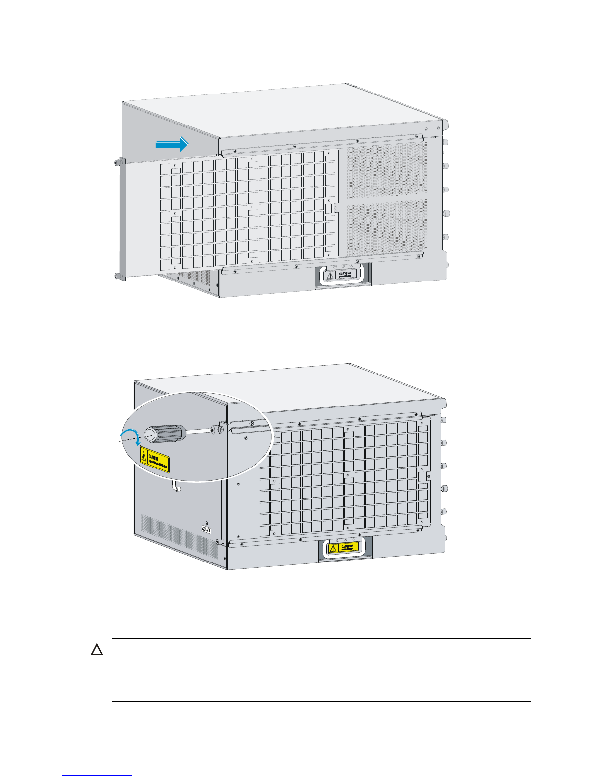
Installing a fan tray
Follow these steps to install a fan tray:
1. Gently push the fan tray slowly along the slide rails into the slot until it touches the slot bottom.
Page 28
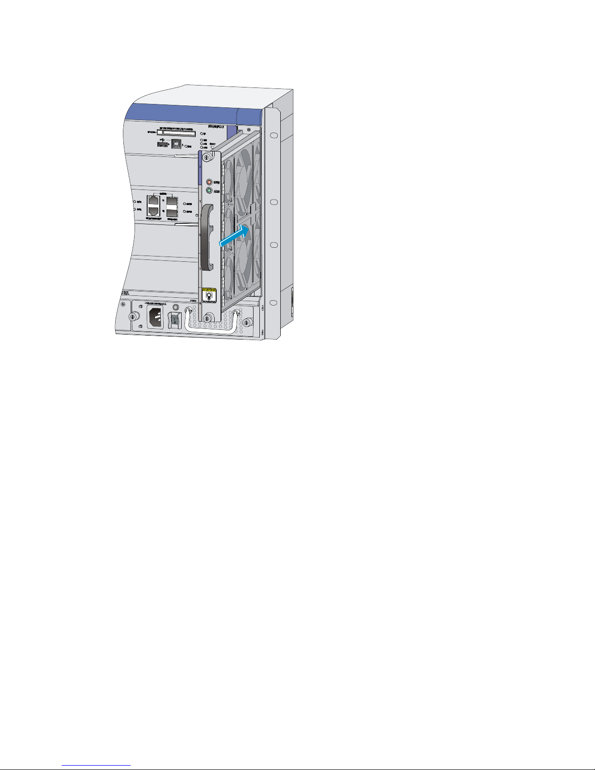
22
Figure 21 Push the fan tray into the slot
2. Use a Phillips screwdriver to fasten the captive screws on the fan tray.
3. After the firewall is powered on, the RUN LED of the fan tray is steady on. This means that the fan
tray runs properly. For the LED description of the fan tray, see the chapter “Appendix B LEDs.”
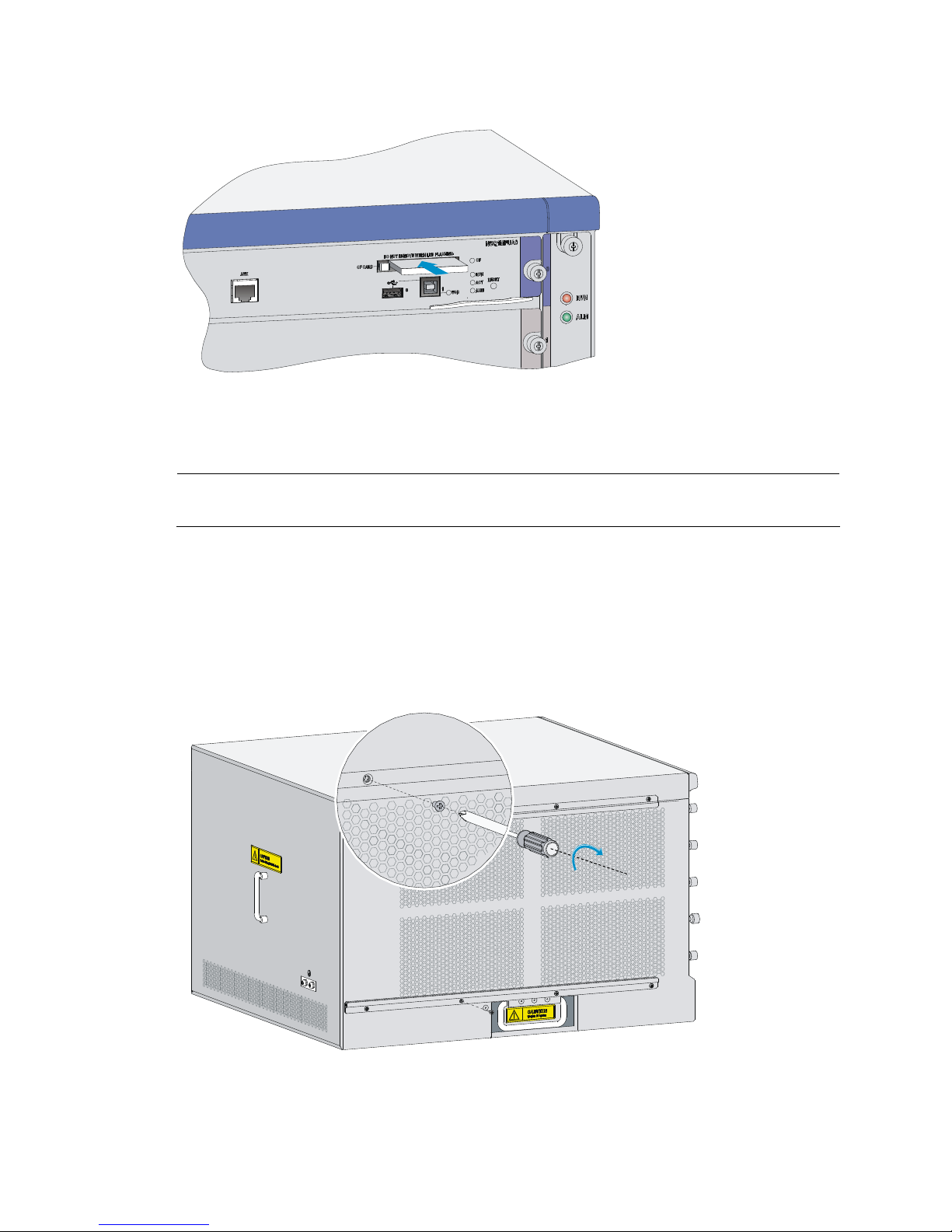
Installing a CF card
Follow these steps to install a CF card:
1. Push the CF card eject button all the way into the slot, and make sure that the button does not
project from the panel.
2. Insert the CF card into the slot following the direction shown in Figure 22, and make sure it does
not project from the slot.
Page 29
23
Figure 22 Insert the CF card into the slot
Installing an air filter (optional)
NOTE:
You must install the air filter before you install the mounting brackets.
The air filter of the A-F5000 is installed at the air intake vents on the left of the chassis (when you face the
front panel of the chassis) to prevent dust from entering the chassis.
Follow these steps to install an air filter:
1. Install the upper and lower slide rails to the chassis: use a Phillips screwdriver to fasten the screws
on the slide rails, as shown in Figure 23.
Figure 23 Install the air filter slide rail
s
2. Push the air filter along the slide rails into the chassis.
Page 30
24
Figure 24 Insert the air filter into the slide rails
3. Fasten the captive screws on the air filter with a Phillips screwdriver.
Figure 25 Fasten the captive screws
Installing a power supply
CAUTION:
• The A-F5000 supports both AC and DC power supplies. You must install either AC or DC power
supplies to the firewall.
• The A-F5000 needs only one power supply for the whole system to operate properly.
Page 31

25
NOTE:
Typically the firewall does not provide a filler panel for one of the power supply slots. You can install a
power supply in that slot.
The procedures for installing an AC power supply and DC power supply are the same. The following uses
an AC power supply as an example.
1. Remove the filler panel (if any) from the slot you want to install a power supply: use a Phillips
screwdriver to loosen the captive screws on the filler panel until all spring pressure is released, and
then remove the filler panel.
2. Use even pressure to gently push the power supply slowly along the slide rails into the slot.
Figure 26 Insert the power supply into the slot
3. Fasten the captive screws on the power supply with a Phillips screwdriver.
4. After the firewall is powered on, and the power supply LED is green, the power supply works
properly. If the LED is red, the power supply has failed. For the power supply LED description, see
the chapter “Appendix B LEDs.”
Connecting a power cord
Connecting an AC power cord
Follow these steps to connect an AC power cord:
1. Switch off the AC power supply.
2. Make sure the firewall is well grounded.
3. Connect one end of the AC power cord to the AC receptacle on the firewall, and the other end to
the AC power source.
4. Fix the power cord to the power supply handle by using a cable tie.
Page 32

26
Figure 27 Connect an AC power cord to the firewall
Connecting a DC power cord
Follow these steps to connect a DC power cord:
1. Switch off the DC power supply.
2. Remove the protection cover from the DC power supply.
3. Remove the screws from the terminals on the DC power supply with a Phillips screwdriver.
4. Connect the end marked with “– “ of the supplied blue DC power cord to the negative terminal (–)
on the power supply and fasten the screw.
5. Connect the end marked with “+“ of the supplied black DC power cord to the positive terminal (+)
on the power supply and fasten the screw.
6. Connect the other end of the DC power cord to the DC power source.
7. Cover the protection cover of the DC power supply.
Figure 28 Connect the DC power cord
WARNING!
Identify the label on the DC power cord when connecting a DC power cord to avoid connection mistakes.
Connecting Ethernet cables
Connecting a copper Ethernet cable
Follow these steps to connect a copper Ethernet cable:
1. Plug one end of an Ethernet twisted pair cable into the copper Ethernet port (RJ-45 port) to be
connected on the firewall and the other end of the cable into the Ethernet port of the peer device.
The Ethernet ports of the firewall support MDI/MDIX auto-sensing. You can use straight-through or
crossover Ethernet cables.
Page 33

27
2. After the firewall is powered on, check the status LED of the Ethernet ports. If the LED is solid green,
the connection is normal. For more information about the LED status, see the chapter “Appendix B
LEDs.”
NOTE:
For more information about Ethernet twisted pair cables, see the chapter “Appendix C Cables.”
Connecting an optical fiber
Before connecting the firewall to the network, you must install a transceiver module to the firewall, and
then insert the fiber connector to the transceiver module. The A–F5000 supports LC connectors only.
Follow these steps to connect optical fibers:
1. Remove the dust plug from a fiber port of the firewall.
Figure 29 Remove the dust plug
2. Install the transceiver module, as shown in Figure 30.
Page 34

28
Figure 30 Install the transceiver module
3. Remove the dust cap from the transceiver module and the protective caps from the fibers.
4. Plug the LC connectors on one end of the fiber cable into the Rx and Tx ports, and plug the LC
connectors on the other end to the Tx and Rx ports on the peer device, as shown in Figure 31.
Figure 31 Connect the fi
ber connectors
5. After the firewall is powered on, and the LEDs of the optical interfaces are steady on, the
connection is normal. For more information about the LED status, see the chapter “Appendix B
LEDs.”
IMPORTANT:
For more information about the optical fibers, see the chapter “Appendix C Cables.”
Note the following guidelines:
Page 35

29
• Never bend or curve a fiber when connecting it. The bend radius must be not less than 10 cm (3.94
in).
Figure 32 Bend radius of the fiber
• Ensure the cleanness of the fiber ends.
WARNING!
To avoid injury to your eyes, do not stare at the optical interfaces and optical fiber connectors when
connecting optical fibers.
Page 36

30
Logging in to the firewall and configuring basic
settings
This chapter includes these sections:
• Logging in to the firewall through the console port
• Powering on the firewall
• Logging in to the firewall through Telnet
• Logging to the firewall through a web browser
• Performing basic settings for the firewall
T
his chapter describes only the commonly used methods for logging in to the firewall. For more firewall
login methods, such as login through SSH and NMS, see the configuration guides for the firewall.
Logging in to the firewall through the console port
Connecting the firewall to a configuration terminal
Follow these steps to connect a configuration terminal to the firewall by using the console cable:
1. Select a configuration terminal, which can be a character terminal with an RS232 serial port, or
a PC.
2. Plug the DB-9 female connector to the serial port of the configuration terminal and connect the
RJ-45 connector to the console port of the firewall.
Figure 33 Connect the console cable
Page 37

31
CAUTION:
• When you connect the console cable, HP recommends connecting the DB-9 connector of the console
cable to the serial port, and then the RJ-45 connector to the console port of the firewall.
• When you remove the console cable, HP recommends removing the RJ-45 connector, and then the DB-9
connector.
Setting terminal parameters
To configure and manage the firewall, you must run a terminal emulator program on the configuration
terminal, for example, a PC. This section uses Windows XP HyperTerminal as an example.
Follow these steps to set terminal parameters on a PC:
1. Select Start > All Programs > Accessories > Communications > HyperTerminal to enter the
HyperTerminal window. The Connection Description dialog box appears, as shown in Figure 34.
Figure 34 Connection description
of the HyperTerminal
2. Type the name of the new connection in the Name text box and click OK. The following dialog box
appears. Select the serial port to be used from the Connect using drop-down list.
Page 38

32
Figure 35 Set the serial port used by the HyperTerminal connection
3. Click OK after selecting a serial port and the following dialog box appears. Set Bits per second to
9600, Data bits to 8, Parity to None, Stop bits to 1, and Flow control to None.
Page 39

33
Figure 36 Set the serial port parameters
NOTE:
To use the default settings, click Restore Defaults.
4. Click OK after setting the serial port parameters and the system enters the following interface.
Figure 37 HyperTerminal window
Page 40

34
5. Click Properties in the HyperTerminal window to enter the test Properties dialog box. Click the
Settings tab, set the Emulation to VT100, and then click OK.
Powering on the firewall
Checking before power-on
Before powering on the firewall, verify the following items:
• The power cord and grounding cable are properly connected.
• The power source voltage meets the requirement of the firewall.
• The console cable is properly connected, the terminal or PC used for configuration has started, and
the configuration parameters have been set.
• If a CF card is used, check that the CF card is in position.
WARNING!
Before powering on the firewall, locate the power switch so that you can disconnect the power supply in
time in case of an emergency.
Powering on the firewall
• Power on the power source.
• Power on the AC or DC power supply of the firewall.
Checking after power-on
After powering on the firewall, verify the following items:
• The LEDs on the front panel of the main processing unit (MPU) are normal. For the LED description,
see the chapter “Appendix B LEDs.”
• The fans are working properly, and you can hear fan rotating.
• The configuration terminal displays information normally. If you log in through the console port, you
can see the startup page on the configuration terminal after powering on the firewall.
• After the power-on self-test (POST), the system prompts you to press Enter. When the command line
prompt appears, the firewall is ready for configuration.
Logging in to the firewall through Telnet
NOTE:
For more information about the Telnet login, see the configuration guides for the firewall.
You can use the default information to log in to the A-F5000 firewall. The default login information
includes:
• Username: admin
• Password: admin
• IP address of port M-GigabitEthernet 0/0: 192.168.0.1/24
Page 41

35
Follow these steps to log in to the firewall through Telnet:
1. Log in to the A-F5000 through the console port and then use the telnet server enable command in
system view to enable the Telnet function of the firewall.
By default, Telnet is disabled on the firewall.
2. Connect port M-GigabitEthernet 0/0 of the A-F5000 to a PC by using an Ethernet cable.
3. Configure an IP address for the PC, ensuring the PC and the A-F5000 can ping each other.
Set the IP address to any one but 192.168.0.1 within the range of 192.168.0.0/24. For example, set the
address to 192.168.0.2.
4. Use the Telnet command to log in to the firewall.
Logging to the firewall through a web browser
The A-F5000 supports web-based network management, which allows you to manage and maintain the
firewall in a more user-friendly way.
Your A-F5000 firewall was delivered with the default web logging information. You can use this default
information to log in to the web page of your firewall. The default web logging information includes:
• User name: admin
• Password: admin
• IP address of the management Ethernet port M-GigabitEthernet 0/0: 192.168.0.1/24
Follow these steps to log in to your firewall through a web browser:
1. Connect a cable to the A-F5000.
Connect the management Ethernet port of the A-F5000 to a PC by using a network cable.
2. Configure an IP address for the PC, ensuring the PC and the A-F5000 can ping each other.
Set the IP address to any one but 192.168.0.1 within the range of 192.168.0.0/24. For example, set the
address to 192.168.0.2.
3. Launch the web browser and input the login information.
Launch the web browser on the PC. Type 192.168.0.1 in the address bar and press Enter. The login dialog
box appears, as shown in Figure 38. In thi
s dialog box, enter your user name (admin), password (admin),
verify code and click Login.
Figure 38 Web login dialog box
Then, the web interface of the A-F5000 firewall appears.
Page 42

36
Performing basic settings for the firewall
This section describes the fast configuration by using the basic configuration wizard. For more
information about how to configure the protocols and features for the A-F5000 firewall, see the
configuration guides for the firewall.
NOTE:
The web interfaces may vary by the software version.
Launching the basic configuration wizard
Select Wizard from the navigation tree to enter the Configuration Wizard page, and then click the Basic
Device Information hyperlink to enter the first page of the basic configuration page, as shown in Figure
39.
Figure 39 Basic c
onfiguration wizard: 1/6
Configuring the system name and user password
Click Next on the first page of the basic configuration wizard to enter the basic information configuration
page, as shown in Figure 40.
Page 43

37
Figure 40 Basic configuration wizard: 2/6 (basic information)
Table 7 Basic information configuration items
Item Description
Sysname Set the system name. By default, the system name of the firewall is HP.
Modify Current User
Password
New Password
Confirm Password
Specify whether to modify the login password of the current user.
To modify the password of the current user, set the new password and the confirm
password, and the two passwords must be identical.
By default, the firewall login username and password are both admin.
Configuring service management
Click Next on the basic information configuration page to enter the service management page, as shown
in Figure 41.
Page 44

38
Figure 41 Basic configuration wizard: 3/6 (service management)
Table 8 Service management configuration items
Item Description
FTP
Specify whether to enable FTP on the device.
Disabled by default.
Telnet
Specify whether to enable telnet on the device.
Disabled by default.
HTTP
Specify whether to enable HTTP on the device, and set the HTTP port number.
Enabled by default.
IMPORTANT:
• If the current user has logged in to the web interface through HTTP, disabling HTTP
or modifying the HTTP port number will result in disconnection with the device;
therefore, perform the operation with caution.
• When you modify a port number, ensure that the port number is not used by
another service.
Page 45

39
Item Description
HTTPS
Specify whether to enable HTTPS on the device, and set the HTTPS port number.
HTTPS is the HTTP protocol that supports the Secure Sockets Layer (SSL) protocol. It
can improve device security. For more information about HTTPS.
Disabled by default.
IMPORTANT:
• If the current user logged in to the web interface through HTTPS, disabling HTTPS
or modifying the HTTPS port number will result in disconnection with the device;
therefore, perform the operation with caution.
• When you modify a port number, ensure that the port number is not used by
another service.
• By d e fault, HTT PS uses the PKI domain default. If this PKI domain does not exist, the
system will prompt you for it when the configuration wizard is completed; however,
this will not affect the execution of other configurations.
Configuring the IP address for an interface
Click Next on the service management configuration page to enter the interface IP address configuration
page, as shown in Figure 42. T
he table lists the IP address configuration information for all Layer 3
Ethernet interfaces and VLAN interfaces. You can click a value in the table and then modify it. Only when
the IP configuration is Static Address, you can configure the IP address and mask.
Figure 42 Basic configuration wizard: 4/6 (interface IP configuration)
Page 46

40
Table 9 Interface IP address configuration items
Item Description
IP Configuration
Set the approach for obtaining the IP address, including:
• None: The IP address of the interface is not specified,
that is, the interface has no IP address.
• Static Address: Specify the IP address for the interface
manually; if you select this item, you need to specify
both the IP address and the mask.
• DHCP: The interface obtains an IP address
automatically through the DHCP protocol.
• Do not change: The IP address of the interface does not
change.
IP Address
Mask
If you select Static Address as the approach for obtaining
the IP address, you need to set the interface IP address and
network mask.
IMPORTANT:
Modification to the
interface IP address will
result in disconnection
with the device, so make
changes with caution.
Configuring NAT
Click Next on the interface IP address configuration page to enter the NAT configuration page, as shown
in Figure 43.
Figure 43 Basic c
onfiguration wizard: 5/6 (NAT configuration)
Page 47

41
Table 10 NAT configuration items
Item Description
Interface
Select an interface on which the NAT configuration will be applied. Generally, it is
the outgoing interface of the device.
Dynamic NAT
Specify whether to enable dynamic NAT on the interface.
If dynamic NAT is enabled, the IP address of the interface will be used as the IP
address of a matched packet after the translation.
By default, dynamic NAT is disabled.
Source IP/Wildcard If dynamic NAT is enabled, set the source IP address and wildcard for packets.
Destination
IP/Wildcard
If dynamic NAT is enabled, set the destination IP address and wildcard for packets.
Protocol Type
If dynamic NAT is enabled, select the protocol type carried over the IP protocol,
including TCP, UDP, and IP (indicating all protocols carried by the IP protocol).
Internal Server
Specify whether to enable the internal server.
You can configure an internal server on the NAT device by mapping a public IP
address and port number to the private IP address and port number of the internal
server.
By default, the internal server is disabled.
IMPORTANT:
Configuration of the internal server may result in disconnection with the device (for
example, specify an external IP address as the IP address of the local host or as the IP
address of the current access interface). Perform the operation with caution.
External IP: Port
When the internal server is enabled, set the valid IP address and service port number
for the external access.
Internal IP: Port
If the internal server is enabled, set the IP address and service port number for the
server on the internal LAN.
Completing the configuration wizard
Click Next on the NAT configuration page to enter the page shown in Figure 44.
Page 48

42
Figure 44 Basic configuration wizard: 6/6
This page lists all configurations you have made in the basic configuration wizard. Confirm the
configurations. To modify your configuration, click Prev to go back to the previous page; if no
modification is needed, click Finish to execute all configurations.
Page 49

43
Hardware management and maintenance
This chapter includes these sections:
• Displaying hardware information of the firewall
• Solving system faults
• Saving the current configuration of the firewall
• Rebooting a module or the firewall
NOTE:
The output depends on your firewall model. For more information about the commands used in this
chapter, see the corresponding command references.
Displaying hardware information of the firewall
Displaying the software and hardware version information of
the firewall
Use the display version command to display software and hardware version information of the firewall.
The output includes the following information: the current software version and hardware version, firewall
operating time, type and operating time of each main processing unit (MPU) and interface module. The
output of this command depends on your firewall model.
<Sysname> display version
HP Comware Platform Software
Comware Software, Version 5.20, Release 3206P18
Copyright (c) 2010-2011 Hewlett-Packard Development Company, L.P.
HP A-F5000 uptime is 0 week, 0 day, 0 hour, 3 minutes
2048M bytes DDR2 SDRAM Memory
4M bytes Flash Memory
247M bytes CF0 Card
MPUA PCB Version:Ver.B
SWBA PCB Version:Ver.A
MPUA Basic Logic Version: 3.0
MPUA Extend Logic Version: 1.0
SWBA Logic Version: 1.0
MPUA LX30T FPGA Version: 5.05
Basic BootWare Version: 1.07
Extend BootWare Version: 1.09
[FIXED PORT] CON (Hardware)Ver.B, (Driver)1.0, (Cpld)3.0
[FIXED PORT] AUX (Hardware)Ver.B, (Driver)1.0, (Cpld)3.0
[FIXED PORT] M-GE0/0 (Hardware)Ver.B, (Driver)1.0, (Cpld)3.0
[FIXED PORT] H-GE0/1 (Hardware)Ver.B, (Driver)1.0, (Cpld)3.0
Page 50

44
[SUBCARD 1] NSQ1GT8C40 (Hardware)Ver.B, (Driver)1.0, (Cpld)1.0
[SUBSLOT 2] The SubCard is not present
[SUBSLOT 3] The SubCard is not present
[SUBSLOT 4] The SubCard is not present
Displaying the operational statistics of the firewall
When you perform routine maintenance or the system fails, you may need to view the operational
information of each functional module for locating failures. Generally, you need to run display
commands one by one. To collect more information one time, you can execute the display
diagnostic-information command in any view to display or save the operational statistics of multiple
functional modules of the firewall. This command displays the output of the display clock, display version,
display device, display current-configuration commands, and so on.
• To save the operational statistics of each functional module of the firewall, type y when the system
prompts you to save or display the diagnostic information.
<Sysname> display diagnostic-information
Save or display diagnostic information (Y=save, N=display)? [Y/N]:y
Please input the file name(*.diag)[cfa0:/default.diag]:aa.diag
Diagnostic information is outputting to cfa0:/aa.diag.
Please wait...
Save successfully.
Execute the more aa.diag command in user view, and then press the Page Up and Page Down keys to
view the contents of the file aa.diag.
• To display the operational statistics of each functional module of the firewall, type n when the
system prompts you to save or display the diagnostic information. The output is too much and
omitted here.
<Sysname> display diagnostic-information
Save or display diagnostic information (Y=save, N=display)? [Y/N]:n
=================================================
===============display clock===============
=================================================
08:54:16 UTC Fri 11/12/2010
===================================================
===============display version===============
===================================================
…Omitted…
Displaying the detailed information about a module
Use the display device verbose command to display detailed information of modules in each slot.
<Sysname>display device verbose
Status : OK
Type : RPU
MPUA PCB : B
SWBA PCB : A
MPUA Basic CPLD: 3.0
MPUA Extend CPLD: 1.0
SWBA CPLD: 1.0
Page 51

45
MPUA LX30T FPGA: 5.05
Driver : 1.0
SubCard Num : 5
CFCard Num : 2
Usb Num : 2
The SubCard1 on Board0:
Status : Normal
Type : NSQ1GT8C40
LPUA PCB : B
12GEA PCB : A
LPUA Basic CPLD: 1.0
LPUA Extend CPLD: 2.0
12GEA CPLD: 2.0
LPUA LX30T FPGA: 5.05
LPUA LX110 FPGA: 5.05
LPUA MEMORY SIZE: 512M bytes
Driver : 1.0
The SubCard2 on Board0:
Status : Absent
The SubCard3 on Board0:
Status : Absent
The SubCard4 on Board0:
Status : Absent
Displaying the electrical label information of a module
Use the display device manuinfo command to display the electrical label information of the module in
each slot.
<Sysname> display device manuinfo
slot 0
DEVICE_NAME :XXX
DEVICE_SERIAL_NUMBER :XXX
MAC_ADDRESS :000f-e123-4567
MANUFACTURING_DATE :2011-02-24
VENDOR_NAME :HP
slot 1
DEVICE_NAME :XXX
DEVICE_SERIAL_NUMBER :XXX
MAC_ADDRESS :0023-8900-2001
MANUFACTURING_DATE :2011-02-02
VENDOR_NAME :HP
Page 52

46
Displaying the CPU usage of a module
Use the display cpu-usage command to display the CPU usage of the module in each slot.
<Sysname> display cpu-usage
Unit CPU usage:
3% in last 5 seconds
3% in last 1 minute
3% in last 5 minutes
Table 11 Output description
Field Description
3% in last 5 seconds
Average CPU usage in the last five seconds (after the firewall boots, the
firewall calculates and records the average usage at the interval of five
seconds).
3% in last 1 minute
Average CPU usage in the last one minute (after the firewall boots, the
firewall calculates and records the average usage at the interval of one
minute).
3% in last 5 minutes
Average CPU usage in the last five minutes (after the firewall boots, the
firewall calculates and records the average usage at the interval of five
minutes).
Displaying the memory usage of the MPU
Use the display memory command to display the memory information of the MPU.
<Sysname> display memory
System Total Memory(bytes): 1874838960
Total Used Memory(bytes): 552515624
Used Rate: 29%
Displaying the CF card information
Use the display device cf-card command to display the CF card information.
<Sysname> display device cf-card
Compacted Flash Card Information:
CF ID 1
Status: Normal
Size : 247M bytes
CF ID 2
Status: Absent
Table 12 Output description
Field Description
CF ID Slot number of the CF card
Status:
Operational status of the CF card:
• Absent—No CF card is present in the slot.
• Fault—The CF card fails.
• Normal—The CF card is operating properly.
Page 53

47
Field Description
Size: Storage capacity of the CF card
Displaying the operational status of the fan
Use the display fan command to display the operational status of the fan.
<Sysname> display fan
Fan 1 State: Normal
Table 13 Output description
Field Description
Fan 1 Number of the fan
State
The fan state:
• Normal—The fan is operating properly.
• Absent—The fan is not in position.
• Fault—The fan fails.
Displaying the operational status of power supplies
Use the display power command to display the operational status of power supplies.
<Sysname> display power
Power Information:
Power 1 Status: Normal
Power 2 Status: Absent
Table 14 Output description
Field Description
Power 1 Number of the power supply
Status
The power supply state:
• Normal—The power supply is operating properly.
• Absent—The power supply is not in position.
• Fault—The power supply fails.
Solving system faults
Solving system faults
When the system detects faults (such as system instruction faults, invalid addresses, data overflow, null
pointers, and division by zero operations) during the operation of the MPU, you can solve the problem
in one of the following methods:
• reboot: Rebooting the failed MPU so that the MPU restores to normal operational status.
• maintain: Maintaining the current status of the failed MPU so that the system does not take any
restoration measures. Some software faults are hard to reproduce, and the printed information will
Page 54

48
be lost after the firewall reboots. In this case, you can maintain the current status of the firewall,
facilitating fault location.
Follow these steps to solve system faults:
To do… Use the command… Remarks
Enter system view system-view —
Specify the system fault solving
method for the MPU
system-failure { maintain |
reboot }
Optional
reboot by default for the MPU.
NOTE:
• Rebooting the MPU reboots the firewall.
• If an interface module encounters software faults, the solving method is always reboot, which reboots the
failed module.
• When system faults occur, the system fault solving method applies to only the failed module, and
rebooting the module does not interrupt the other modules.
Viewing the system fault solving method
Use the display system-failure command to display the system fault solving method.
<Sysname> display system-failure
System failure handling method: reboot
Saving the current configuration of the firewall
You can save the current configuration of the firewall in one of the following methods:
• Fast saving: Executing the save command without the safely keyword. This m ode saves the file more
quickly but is likely to lose the existing configuration file if the firewall reboots or the power fails
during the process. The fast saving mode is suitable for environments where the power supply is
stable.
• Safe saving: Executing the save command with the safely keyword. The mode saves the file more
slowly but can retain the configuration file in the firewall even if the firewall reboots or the power
fails during the process. The safe saving mode is preferred in environments where a stable power
supply is unavailable or remote maintenance is involved.
Follow these steps to save the current configuration of the firewall:
To do… Use the command… Remarks
Save the current configuration to
the specified file, but the
configuration file will not be set as
the file for the next startup
save file-url [ all | slot slot-number ]
Save the current configuration to
the root directory of the storage
medium of the MPU and specify the
file as the startup configuration file
that will be used at the next system
startup
save [ safely ]
Use either command
Available in any view
Page 55

49
NOTE:
• The configuration file must be with extension .cfg.
• During the execution of the save
command, the startup configuration file to be used at the next system
startup may be lost if the firewall reboots or the power supply fails. In this case, the firewall will boot with
the factory defaults, and after the firewall reboots, you need to re-specify a startup confi
g
uration file for
the next system startup.
Rebooting a module or the firewall
To reboot a firewall, use one of the following methods:
• Use the reboot command to reboot a firewall.
• Enable the scheduled reboot function at the CLI. You can set a time at which the firewall can
automatically reboot, or set a delay so that the firewall can automatically reboot within the delay.
• Power on the firewall after powering it off, which is also called hard reboot or cold start. Powering
off a running firewall causes data loss and hardware damages, and therefore is not recommended.
Perform the following operation to reboot the firewall immediately:
To do… Use the command… Remarks
Reboot the firewall or the module
in the specified slot immediately
reboot [ slot slot-number ]
Required
Available in user view
Perform the following operation to enable the scheduled reboot function:
To do… Use the command… Remarks
Enable the scheduled reboot
function and specify a specific
reboot time and date
schedule reboot at hh:mm [ date ]
Enable the scheduled reboot
function and specify a reboot
waiting time
schedule reboot delay { hh:mm |
mm }
Use either command
The scheduled reboot function is
disabled by default.
Available in user view
CAUTION:
• If you execute the reboot command without specifying the slot keyword, the command reboots the
firewall.
• If no host software file is specified, do not use the reboot command to reboot the firewall. In this case,
you should specify the host software file first, and then reboot the firewall.
• The precision of the rebooting timer is 1 minute. One minute before the rebooting time, the firewall
prompts “REBOOT IN ONE MINUTE” and reboots in one minute.
• If you are performin
g
file operations when the firewall is to be rebooted, the system does not execute the
reboot command for security.
Page 56

50
Replacement procedures
This chapter includes these sections:
• Safety recommendations
• Replacing a power supply
• Replacing an MPU
• Replacing an interface module
• Replacing a transceiver module
• Replacing a CF card
• Replacing a fan tray
• Replacing an air filter
Safety recommendations
1. Always wear an ESD-preventive wrist strap or ESD-preventive gloves when replacing the modules.
2. When operating a pluggable module, such as a the MPU, interface module, or CF card, note the
following guidelines:
• Ensure good alignment with the slot to avoid damage to the module during installation or removal.
• Before removing a module, make sure that the captive screws are completely loosened.
• Avoid touching any components on the PCB during observing or moving the module.
• Put the removed module on an antistatic workbench with the PCB side facing upward or place them
in antistatic bags.
Replacing a power supply
The replacement procedure of an AC power supply is the same as a DC power supply. This section takes
an AC power supply as an example.
Follow these steps to replace a power supply:
1. Switch off the power supply.
2. Turn off the circuit breaker at the power input end.
3. Remove the AC power cord.
4. Use a Philips screwdriver to loosen the captive screws of the power supply to be removed until all
spring pressure is released.
5. Gently pull the power supply out of the slot along the slide rails.
Page 57

51
Figure 45 Pull out the power supply
6. Install a new power supply. For how to install a power supply, see the chapter “Installing the
firewall.”
Replacing an MPU
CAUTION:
The MPU does not support hot swapping. Before replacin
g
an MPU, you must switch off the power supply
of the firewall.
Follow these steps to replace a MPU:
1. Switch off the power supply.
2. Use a Philips screwdriver to loosen the captive screws of the MPU to be removed until all spring
pressure is released.
3. Holding the ejector levers of the MPU with both hands, pull the ejector levers outward, and gently
pull the MPU out of the slot along the slide rails.
Figure 46 Pull the MPU out of the slot
4. Install a new MPU. For how to install an MPU, see the chapter “Installing the firewall.”
Page 58

52
Replacing an interface module
CAUTION:
The interface module does not support hot swapping. Before replacing an interface module, you must
switch off the power supply of the firewall.
Follow these steps to replace an interface module:
1. Switch off the power supply.
2. Determine the interface module to be removed. This section takes the interface module in slot 2 as
an example.
3. Remove the cables from the interface module.
4. Use a Philips screwdriver to loosen the captive screws of the interface module to be removed until
all spring pressure is released.
5. Holding the ejector levers of the interface module with both hands, pull the ejector levers outward,
and gently pull the interface module out of the slot along the slide rails.
Figure 47 Pull the interface module out of the slot
6. Install a new interface module. For how to install a new interface module, see the chapter
“Installing the firewall.”
Replacing a transceiver module
NOTE:
When replacin
g
a transceiver module, make sure that the two transceiver modules connected by the same
optical fiber have the same wavelength.
Follow these steps to replace a transceiver module:
1. Remove the optical fibers from the transceiver module.
2. Pivot the clasp down to the horizontal position.
3. As shown in Figure 48, holding the handle of the transceiver module, gently pull the transceiver
module out.
Page 59

53
4. Insert the dust cap to the removed transceiver module, and put the transceiver module into its
original shipping materials.
5. If you do not install a new transceiver module in the interface, install a dust-proof plug in the
interface. For how to install a transceiver module, see the chapter “Installing the firewall.”
Figure 48 Remove a transceiver module
WARNING!
• Do not stare into the optical fibers.
• When removing a transceiver module, do not touch the golden finger of the transceiver module.
Replacing a CF card
CAUTION:
To avoid hardware damage, do not remove the CF card when the firewall is booting or the CF LED is
flashing.
Follow these steps to replace a CF card:
1. Make sure that the CF card LED is not flashing. A flashing CF card LED means that the system is
accessing the CF card.
2. Press the CF card eject button of the CF card so that the eject button projects from the panel.
Page 60

54
Figure 49 Press the eject button
3. Press the eject button again to eject the CF card part-way out of the CF card slot, and then pull the
CF card out of the CF card slot.
Figure 50 Press the eject button to eject the CF card
4. Install a new CF card. For more information, see the chapter “Installing the firewall.”
Replacing a fan tray
CAUTION:
• The firewall supports automatic fan speed adjustment and hot-swapping of the fan tray.
• Keep your hands away from the spinning fan blades when removing the fan tray.
Follow these steps to replace a fan tray:
1. Use a Philips screwdriver to loosen the captive screws of the fan tray to be removed until all spring
pressure is released.
2. Gently pull the fan tray out of the slot along the slide rails.
Page 61

55
Figure 51 Pull out the fan tray
3. Install a new fan tray. For more information, see the chapter “Installing the firewall.”
NOTE:
• Do not keep the firewall working without a fan tray for over two minutes because poor ventilation ma
y
result in damage to the firewall.
• To protect the removed fan tray, place it in an antistatic bag.
Replacing an air filter
NOTE:
An air filter is an optional accessory.
Follow these steps to replace an air filter:
1. Use a Philips screwdriver to loosen the captive screws of the air filter to be removed until all spring
pressure is released.
Page 62

56
Figure 52 Loosen the captive screws of the air filter
2. Gently pull the air filter out along the slide rails.
Figure 53 Pull the air filter out along the slide rails
3. Install a new air filter. For more information, see the chapter “Installing the firewall.”
CAUTION:
You can clean the air filter with water, but wait until it is completely dry before installing it again.
Page 63

57
Troubleshooting
This chapter includes these sections:
• MPU failures
• Interface module failures
• Power supply failures
• Fan failures
• Configuration system problems
• Using the AUX port as the backup console port
• Password loss
• Cooling system failure
• Host software file missing errors
NOTE:
The barcode stuck on the firewall chassis contains production and servicin
g
information. Before you return
a faulty firewall for serving, provide the barcode information of the firewall to your local sales agent.
MPU failures
RUN LED is off
When the RUN LED of the MPU is off, it indicates that the MPU is powered off or faulty. For more
information about the RUN LED, see the chapter “Appendix B LEDs.”
Follow these steps to troubleshoot the MPU failure:
1. Check whether the MPU is plugged in a right slot (slot 0).
2. Check whether the firewall is powered on normally. A green POWER LED indicates that the
firewall is powered on normally.
3. If the cause cannot be located in the steps above and the problem persists, contact your local sales
agent.
RUN LED fast flashes
Five minutes after the firewall is powered on or the MPU is plugged into the firewall, if the RUN LED of the
MPU still fast flashes at 8 Hz, it indicates that the MPU application program fails to start or the MPU is
faulty.
Follow these steps to troubleshoot the MPU failure:
1. Check whether the terminal display is correct.
2. Check whether the application program file properties are correct in the BootWare menu.
3. If the cause cannot be located in the steps above and the problem persists, contact your local sales
agent.
Page 64

58
ALM LED is steady on or flashes
If the ALM LED of the MPU is steady on or flashes, it indicates that the firewall is faulty.
For example, the ALM LED is on when the system is over-temperature. In this case, the system displays the
following output:
%Jun 25 14:38:45:444 2010 HP DRVMSG/3/TempCritical:
CPU temperature critical in Slot 3, index is 1.
To solve the problem, check the output (such as the system temperature and PCB voltage alarms) on the
serial terminal and the software management tool.
If the cause cannot be located in the steps above and the problem persists, record the above information,
and contact your local sales agent.
Interface module failures
RUN LED is off
If the RUN LED of the interface module is off, it indicates that the interface module is powered off or
faulty.
Follow these steps to troubleshoot the interface module failure:
1. Check whether the firewall is powered on.
2. If the firewall is powered on, check whether the interface module is plugged in a correct slot (slots
1 through 4).
3. If the interface module is plugged in a right slot, you can be sure that the interface module is faulty.
Execute the display version command. The following output appears.
Slot3:
The Board is present, state is unknown
4. If the cause cannot be located in the steps above and the problem persists, contact your local sales
agent.
RUN LED fast flashes
20 minutes after the firewall is powered on or the interface module is plugged into the firewall, if the RUN
LED of the interface module still fast flashes at 8 Hz, it indicates that the interface module application
program fails to start or the interface module is faulty. In this case, the interface module is in position, and
if you enter the display version command, the system displays the following output:
Slot3:
The Board is present, state is unknown
To sole this problem, contact your local sales agent.
Power supply failures
Power LED is off
If the firewall cannot be powered on and the power LED on the front panel is off, it indicates that the
power supply is faulty.
Page 65

59
Follow these steps to troubleshoot the power supply failure:
1. Check whether the power switch is turned on.
2. Check whether the power cables of the firewall are firmly connected.
3. Check whether the switch of the power source is turned on.
4. Check whether the power cable is damaged.
5. If the cause cannot be located in the steps above and the problem persists, contact your local sales
agent.
Red power LED is on
If the firewall cannot be powered on and the red power LED on the front panel is on, it indicates that the
power supply is faulty and has alarms.
Follow these steps to troubleshoot the power supply failure:
1. Switch off the power supply,and check the power supply is firmly seated.
2. Check whether the power source meets the requirements of the firewall.
3. If the cause cannot be located in the steps above and the problem persists, contact your local sales
agent.
Fan failures
Fan tray is absent
After the firewall is booted, the following information may appear on the configuration terminal:
%Jul 5 14:47:20:618 2010 HP DEV/4/FAN ABSENT:
Fan 1 is absent.
The output indicates that the fan tray is not in position.
Follow these steps to troubleshoot the fan tray failure:
1. Check whether the fan tray is in position.
2. Check whether the fan tray is in firm contact with the backplane of the firewall chassis.
3. If the cause cannot be located in the steps above and the problem persists, contact your local sales
agent.
ALM LED is red
When the firewall is running, the ALM LED on the fan tray panel may turn red, and the following
information may appear on the configuration terminal:
%Jul 5 14:59:03:878 2010 HP DRVMSG/3/FanPlugIn:Fan 1 Plug In.
%Jul 5 14:59:03:879 2010 HP DRVMSG/3/FanErr:Fan 1 Error.
#Jul 5 14:59:03:998 2010 HP DEV/1/FAN STATE CHANGES TO FAILURE:
Trap 1.3.6.1.4.1.2010.2.23.1.12.1.6: fan ID is 1
%Jul 5 14:59:03:998 2010 HP DEV/4/FAN FAILED:
Fan 1 failed.
The output shows that fan 1 is faulty.
Page 66

60
To solve the problem, check whether any foreign object has entered the fan tray.
If the cause cannot be located in the steps above and the problem persists, contact your local sales
agent.
Configuration system problems
If the configuration environment setup is correct, the configuration terminal displays boot information
when the firewall is powered on. If the setup is incorrect, the configuration terminal displays nothing or
garbled text.
No terminal display
If the configuration terminal displays nothing when the firewall is powered on, follow these steps to
troubleshoot the failure:
1. Check the following items.
• The power supply system works properly.
• The console cable is properly connected.
2. If no problem is found, check the following reasons that may apply:
• The console cable is connected to an incorrect serial port (the serial port in use is not the one set on
the terminal).
• The properties of the terminal are incorrect. You must configure the console terminal as follows: set
Bits per second to 9600, Data bits to 8, Parity to None, Stop bits to 1, Flow control to None, and
Terminal Emulation to VT100.
• The console cable fails.
3. If the cause cannot be located in the steps above and the problem persists, contact your local sales
agent.
Garbled terminal display
If terminal display is garbled, follow these steps to solve this problem:
1. Make sure that the Data bits field is set to 8 for the console terminal. If the Data bits field is set to
5 or 6, the console terminal will display garbled characters.
2. Make sure that the Bits per second field is set to 9600 kbps. An incorrect bits per second may also
cause the configuration terminal to display garbled characters.
3. Make sure that he AUX interface works in flow mode when the AUX port is used as a backup for
the console port. For more information about the AUX port, see “Using the AUX port as the backup
con
sole port.”
Using the AUX port as the backup console port
When the console port is faulty, you can use the AUX port as the backup console port to complete
firewall configuration as follows:
Follow these steps to configure the AUX user interface at the CLI of the firewall:
To do… Use the command… Remarks
Enter system view system-view —
Page 67

61
To do… Use the command… Remarks
Enter AUX user interface view user-interface aux 0 —
Specify the none authentication mode authentication-mode none Required
Configure the user privilege level user privilege level 3 Required
NOTE:
• To use the default authentication mode (password authentication) for AUX port lo
g
in, you must configure
the user level and password.
• The AUX port can work in the flow mode (default) or protocol mode. The AUX port can be used as the
backup console port only when it works in the flow mode.
• Use the async mode { flow | protocol } command to switch between the flow mode and the protocol
mode. For more information, see the command references for the firewall.
Password loss
User password loss
If you lose your password, you cannot enter the system. In this case, you can boot the system by ignoring
the system configuration.
Follow these steps to solve the user password loss:
1. Enter the main BootWare menu, and select 6 to boot the system by ignoring the system
configuration.
The system prompts the following:
Flag Set Success.
The output indicates that the setting succeeded.
2. When the main BootWare menu appears again, and select 0 to reboot the system.
System start booting...
Booting Normal Extend BootWare....
3. Set a new password in system view after the system reboots.
<Sysname> system-view
[Sysname] user-interface console 0
[Sysname-ui-console0] authentication-mode password
[Sysname-ui-console0] set authentication password simple 123456
The output shows that the console port uses password authentication, and the password is set to 123456
and stored in plain text.
NOTE:
• After reboot, the system runs with the initial default configuration, but the original configuration file is still
stored in the storage medium. To restore the original configuration, use the display saved-confi
g
uration
command to display the configuration, and then copy and execute the configuration.
• If the password is stored in plain text, you can use the display current-configuration command to vie
w
the password in the current configuration. If the password 123 4 5 6 is set with the set authentication
password cipher command, the password is stored in cipher text.
Page 68

62
4. Save the new password.
[Sysname] save
NOTE:
• To save the new password, execute the save command after modifying the user password.
• HP recommends saving the modification as the default configuration file.
Super password loss
In the case of super password loss, you cannot perform higher level operations.
You can clear the super password by selecting 8 on the main BootWare menu.
========================<EXTEND-BootWare MENU>========================
|<1> Boot System |
|<2> Enter Serial SubMenu |
|<3> Enter Ethernet SubMenu |
|<4> File Control |
|<5> Modify BootWare Password |
|<6> Skip Current System Configuration |
|<7> BootWare Operation Menu |
|<8> Clear Super Password |
|<9> Storage Device Operation |
|<0> Reboot |
======================================================================
Enter your choice(0-9):8
The following output indicates that you have successfully cleared the super password.
Clear Application Password Success!
NOTE:
• Select option 8, quit the menu, reboot the firewall, and then you can enter system view directly.
• This setting (password clearing) is valid only for the first reboot of the firewall. The super password will
be restored after a second reboot.
Cooling system failure
When the temperature inside the firewall exceeds 75°C (167°F), the following information appears on
the configuration terminal:
%May 14 21:37:35:271 2010 HP DRVMSG/3/Temp2High:
Environment temperature too high in Slot 0, index is 2.
#May 14 21:37:35:713 2010 HP DEV/1/BOARD TEMPERATURE UPPER:
Trap 1.3.6.1.4.1.2010.2.23.1.12.1.16: frame Index is 0, slot Index 0.0
%May 14 21:37:35:713 2010 HP DEV/4/BOARD TEMP TOOHIGH:
Board temperature is too high on Frame 0 Slot 0, type is MPU.
Page 69

63
The output shows that the temperature inside the firewall has exceeded the upper threshold 75°C (167°F).
In this case, the fans of the firewall will rotate at full speed.
Generally, after the fans rotate at full speed for a certain period, the temperature inside the firewall will
drop below 75°C (167°F), and the following information appears on the configuration terminal:
%May 14 22:25:17:804 2010 HP DRVMSG/3/TempHOK:
Environment temperature recovered from OT in Slot 0, index is 2.
#May 14 22:25:18:713 2010 HP DEV/1/BOARD TEMPERATURE NORMAL:
Trap 1.3.6.1.4.1.2010.2.23.1.12.1.17: frameIndex is 0, slotIndex 0.0
%May 14 22:25:18:713 2010 HP DEV/4/BOARD TEMP NORMAL:
Board temperature changes to normal on Frame 0 Slot 0, type is MPU.
The output shows that the operating temperature of the firewall restores to normal state.
When exceptions occur, the temperature inside the firewall may exceed 90°C (194°F), and the following
information appears on the configuration terminal in this case:
%Jun 25 14:38:45:444 2010 HP DRVMSG/3/TempCritical:
CPU temperature critical in Slot 3, index is 1.
At the same time, the ALM LED of the MPU is red, which indicates that the temperature inside the firewall
is abnormal.
Follow these steps to troubleshoot the cooling system failure:
1. Check whether the fans are running properly.
2. Check whether the working environment of the firewall is well ventilated.
3. Use the display environment command to check whether the temperature in the firewall keeps
rising.
If the temperature inside the firewall exceeds 90°C (194°F), power off the firewall immediately and
contact your local sales agent.
Host software file missing errors
When none of the main, backup, and secure host software files exists, the system displays the following
information at startup:
BootWare Validating...
Application program does not exist.
Please input BootWare password:
If you select 1 on the main BootWare menu, the system displays the following information:
Starting to get the main application file--cfa0:/main.bin!
The main application file does not exist--cfa0:/main.bin!
Starting to get the backup application file--cfa0:/backup.bin!
The backup application file does not exist--cfa0:/backup.bin!
Starting to get the secure application file--cfa0:/secure.bin!
The secure application file does not exist--cfa0:/secure.bin!
Booting App fails!
The name of the main, backup, and secure host software files vary by user settings.
A possible reason for the errors is that the main, backup, and secure host software files have been
deleted or damaged.
Page 70

64
To solve this problem, download the host software file again or set the file properties in the BootWare file
list.
Page 71

65
Appendix A Technical specifications
Dimensions and weight
Table 15 Dimensions and weight
Item Specification
Dimensions (H × W × D) (without mounting brackets) 308 × 436 × 476 mm (12.13 × 17.17 × 18.74 in)
Weight (full configuration) 50 kg (110.23 lb)
Power consumption range
Table 16 Power consumption range of the entire system
Item Specification
Power consumption range 189 W to 460 W
AC power supply
Table 17 AC power supply specifications
Item Specification
Rated voltage range 100 VAC to 240 VAC; 50 Hz or 60 Hz
Maximum input current 10 A
Maximum power 650 W
Dimensions (H × W × D) 40 × 140 × 350 mm (1.57 × 5.51 × 13.78 in)
DC power supply
Table 18 DC power supply specifications
Item Specification
Rated voltage range –60 VDC to –48 VDC
Maximum input current 25 A
Maximum power 650 W
Dimensions (H × W × D) 40 × 140 × 350 mm (1.57 × 5.51 × 13.78 in)
Page 72

66
Fan tray
Table 19 Fan tray specifications
Item Specification
Rated voltage 12 VDC
Total fan power consumption 50 W
Dimensions (H × W × D) 227 × 31 × 413.3 mm (8.94 × 1.22 × 16.27 in)
MPU (NSQ1MPUA0)
Technical specifications
Table 20 NSQ1MPUA0 specifications
Item Specification
Flash 4 MB
Memory type and size
DDR2 SDRAM
4 GB (default, two memory modules, which must be used in pairs)
2 GB (optional)
Console port
1
9600 bps (default) to 115200 bps
AUX port
1
9600 bps (default) to 115200 bps
Management Ethernet
port
1 (10Base-T/100Base-TX/1000Base-T)
HA port 1 (10Base-T/100Base-TX/1000Base-T)
CF card
• 256 MB by default for the built-in CF card
• 256 MB, 512 MB, or 1 GB for an optional external CF card (CF cards less than
256 MB are not supported)
USB ports
2 (USB 0: operating in the host mode; USB 1: operating in the device mode)
Reserved
Power consumption 80 W
Reset button 1
NOTE:
• Flash memory stores the BootWare image.
• The memory stores data during system operation, and caches data for packet forwarding.
• The CF card stores host software files and configuration files.
Page 73

67
Components
CF card
A compact flash (CF) card stores logs, system software image files, and configuration files.
The firewall is equipped with a built-in 256 MB CF card, which is identified with cfa0. In addition, the
firewall provides an external CF card slot to expand the storage space.
The CF cards supported by the firewall are available in the following sizes:
• 256 MB
• 512 M B
• 1 GB
CAUTION:
• Use CF cards provided by HP only. The firewall may be incompatible with other CF cards.
• The CF card is hot-swappable. When the CF card LED is flashing, do not unplu
g
the CF card. Otherwise,
the file system on the CF card may be damaged.
Console port
The firewall provides an RS232 asynchronous serial console port that can be connected to a computer for
system debugging, configuration, maintenance, management, and host software loading.
Table 21 Console port specifications
Item Specification
Connector RJ-45
Standard compliant Asynchronous EIA/TIA-232
Baud rate 9600 bps (default) to 115200 bps
Transmission distance ≤ 15 m (49.21 ft)
Services
• Provides connection to an ASCII terminal
• Provides connection to the serial port of a local PC to run the terminal
emulation program
• Command line interface (CLI)
AUX port
The AUX port is an RS-232 asynchronous serial port. In the event that the console port fails, the AUX port
can be connected to a terminal as a backup port of the console port. For more information, see the
chapter “Troubleshooting.”
Table 22 AUX port specifications
Item Specification
Connector RJ-45
Standard
compliant
Asynchronous EIA/TIA-232
Baud rate 9600 bps (default) to 115200 bps
Page 74

68
Management Ethernet port/HA port
The management Ethernet port is a 10Base-T/100Base-TX/1000Base-T RJ-45 port. It allows you to
upgrade software and manage the firewall through a network management server without using any
service interface of the firewall. The management Ethernet port is used only for managing the firewall
and it has no service processing capabilities such as data forwarding.
High Availability includes features such as stateful failover and VRRP. The HA port on the A-F5000 is a
10Base-T/100Base-TX/1000Base-T auto-sensing RJ-45 port, used to synchronize status packets in
dual-device backup networking.
Table 23 Management Ethernet port/HA port specifications
Item Specification
Connector RJ-45
Interface type Automatic MDI/MDI-X
Number of interfaces
Management Ethernet port: 1
HA port: 1
Frame format
Ethernet_II
Ethernet_SNAP
Interface speed and duplex mode
10 Mbps, half/full-duplex
100 Mbps, half/full-duplex
1000 Mbps, full-duplex
Interface cable and maximum transmission distance
Category-5 twisted pair with a maximum transmission
distance of 100 m (328.08 ft)
RESET button
To reset the current MPU, press the RESET button.
If you press the RESET button when only one MPU is equipped, the whole system will be reset. The RUN
LED goes off when the MPU is reset, flashes fast (at 8 Hz) when BootWare is running, and flashes slowly
(at 1 Hz) after the system is booted and operates properly.
CAUTION:
• If you perform no save operation before resetting the firewall, the current system configuration will be
lost.
• Never press the RESET button when the RUN LED is flashing fast or when the firewall is accessin
g
the CF
card. Otherwise, the file system of the firewall may be damaged.
Page 75

69
Interface modules
NSQ1GT8C40
Table 24 NSQ1GT8C40 specifications
Item Specification
Copper ports
8
10 Mbps, half/full duplex
100 Mbps, half/full duplex
1000 Mbps, full duplex
4
10 Mbps, half/full-duplex
100 Mbps, half/full-duplex
Copper ports (automatic
MDI/MDIX)
1000 Mbps, full-duplex
Combo interfaces
Fiber ports 1000 Mbps, full-duplex
NSQ1XP20
Table 25 NSQ1XP20 specifications
Item Specification
XFP ports
2
10GBASE-R
NSQ1GT8P40
Table 26 NSQ1GT8P40 specifications
Item Specification
Fiber ports
8
1000 Mbps, full duplex
4
10 Mbps, half/full-duplex
100 Mbps, half/full-duplex
Copper ports (automatic
MDI/MDIX)
1000 Mbps, full-duplex
Combo interfaces
Fiber ports 1000 Mbps, full-duplex
Page 76

70
Appendix B LEDs
MPU LEDs
Figure 54 LEDs on the MPU
Table 27 Firewall running status LED description
LED Status Description
Off No link is present.
(green)
Management
port/HA port link
status LED
On A link is present.
Off No data is being received or transmitted.
(yellow)
Management
port/HA port
data transmission
LED
On Data is being received or transmitted.
Off No CF card is present or the CF card is not recognizable.
On A CF card is in position and has been detected.
(green)
CF card LED
Flashing
The CF card is performing a read or write operation. In this
state, do not remove the CF card.
Off No power input is available, or the MPU has failed.
Slow
flashing
(1 Hz)
The MPU is operating properly.
Fast
flashing
(8 Hz)
The application software is being loaded (in this case,
never power off the device or hot-swap the MPU; otherwise
the MPU may be damaged).
(green)
Run LED
Resetting Off after the firewall is reset, and flashes after the firewall
is started.
Page 77

71
LED Status Description
Off The MPU is in standby state or is not powered on.
(yellow)
MPU status LED
On
The MPU is in active state.
NOTE:
The firewall supports one MPU, so the MPU can only be in
active state.
Off The system is operating properly and there is no alarm.
On
A fault has occurred to the system or the available power is
insufficient. In this state, check the system log immediately.
(red)
Alarm LED
Fast
flashing
(8 Hz)
A critical fault has occurred to the system. In this state,
handle the fault immediately.
NOTE:
Do not remove the CF card when the CF LED is flashing. Otherwise, the file system on the CF card will be
damaged.
Interface module LEDs
NSQ1GT8C40/NSQ1GT8P40
Figure 55 NSQ1GT8C40/NSQ1GT8P40 LEDs (NSQ1GT8P40 as an example)
Table 28 Interface module LED description
LED Status Description
Off
No link is present.
Solid green
A 1000 Mbps link is present.
Flashing green
Data is being sent or received at 1000 Mbps.
Solid yellow
A 10/100 Mbps link is present.
(yellow/green)
Copper port LED
Flashing yellow Data is being sent or received at 10/100 Mbps.
Off
No link is present.
Solid green
A link is present.
(green)
SFP port LED
Flashing green
Data is being received or transmitted at 1000
Mbps.
Page 78

72
LED Status Description
Off
No power input is available or the interface module
has failed.
Slow flashing (1
Hz)
The interface module is working properly.
Fast flashing (8
Hz)
Application software is being loaded (in this case,
never power off the interface module or hot-swap
the interface module; otherwise, the interface
module may be damaged).
(green)
Run LED
Resetting
Off after the firewall is reset, and flashes after the
firewall is started.
NSQ1XP20
Figure 56 NSQ1XP20 LEDs
Table 29 Interface module LED description
LED Status Description
Off
No link is present.
On
A link is present, but no data is being sent or
received.
(green)
XFP port LED
Flashing green
Data is being sent or received.
Off
No power input is available or the interface module
has failed.
Slow flashing (1
Hz)
The interface module is working properly.
Fast flashing (8
Hz)
Application software is being loaded (in this case,
never power off the interface module or hot-swap
the interface module; otherwise, the interface
module may be damaged).
(green)
Run LED
Resetting
Off after the firewall is reset, and flashes after the
firewall is started.
Page 79

73
Power supply LEDs
Figure 57 AC power supply LED
Figure 58 DC power supply LED
1
Table 30 AC/DC power LED description
LED Status Description
Solid green The power supply is working properly.
Solid red The power supply is faulty.
Power LED
Off No power is input.
Page 80

74
Fan tray LEDs
Figure 59 Fan tray LEDs
Table 31 Fan tray LED description
LED Status Description
Off The system is powered off or the fan tray is faulty.
(green)
Run LED
On The fan tray is working properly.
Off The fan tray is working properly.
(red)
Alarm LED
On The fan tray is faulty.
Page 81

75
Appendix C Cables
The HP A-F5000 firewall supports various types of interface modules. The port types vary by the interface
module. Use dedicated cables to connect the ports of different types.
Table 32 Cables
Cable Applicable port type Description
Ethernet twisted pair cable RJ-45 Ethernet port
Connects the RJ-45 Ethernet port of
the firewall for data transmission.
Optical fiber SFP/XFP port
Connects the fiber port of the
firewall for data transmission.
Ethernet twisted pair cable
Introduction
An Ethernet twisted pair cable consists of four pairs of insulated copper wires twisted together. Every
wire uses a different color, and has a diameter of about 1 mm (0.04 in). A pair of twisted copper cables
can cancel the electromagnetic radiation of each other, and reduce interference of external sources. An
Ethernet twisted pair cable mainly transmits analog signals and is advantageous in transmitting data
over shorter distances. It is the commonly used transmission media of the Ethernet. The maximum
transmission distance of the Ethernet twisted pair cable is 100 m (328.08 ft). To extend the transmission
distance, you can connect two twisted pair cable segments with a repeater. At most four repeaters can
be added, which means five segments can be joined together to provide a transmission distance of 500
m (1640.42 ft).
Ethernet twisted pair cables can be classified into category 3, category 4, category 5, category 5e,
category 6, and category 7 cables based on performance. In LANs, category 5, category 5e, and
category 6 are commonly used.
Table 33 Description of commonly used Ethernet twisted pair cables
Type Description
Category 5 Suitable for data transmission at a maximum speed of 100 Mbps
Category 5e Suitable for data transmission at a maximum speed of 1000 Mbps
Category 6 Suitable for data transmission at a speed higher than 1 Gbps
Based on whether a metal shielding is used, Ethernet twisted pair cables can be classified into shielded
twisted pair (STP) and unshielded twisted pair (UTP). An STP cable provides a metallic braid between the
twisted pairs and the outer jacket. This metallic braid helps reduce radiation, prevent information from
being listened, and eliminate external electromagnetic interference (EMI) of external sources. STPs have
strict application requirements and are expensive although they provide better EMI prevention
performance than UTPs, so in most LANs, UTPs are commonly used.
An Ethernet twisted pair cable connects network devices through the RJ-45 connectors at the two ends.
Figure 60 sh
ows the pinouts of an RJ-45 connector.
Page 82

76
Figure 60 RJ-45 connector pinout
NOTE:
The RJ-45 Ethernet ports of the HP A-F5000 firewall
use category 5 or higher Ethernet twisted pair cables
for connection.
EIA/TIA cabling specifications define two standards, 568A and 568B, for cable pinouts.
• Standard 568A—pin 1: white/green stripe, pin 2: green solid, pin 3: white/orange stripe, pin 4:
blue solid, pin 5: white/blue stripe, pin 6: orange solid, pin 7: white/brown stripe, pin 8: brown
solid.
• Standard 568B—pin 1: white/orange stripe, pin 2: orange solid, pin 3: white/green stripe, pin 4:
blue solid, pin 5: white/blue stripe, pin 6: green solid, pin 7: white/brown stripe, pin 8: brown
solid.
Ethernet twisted pair cables can be classified into straight-through and crossover cables based on their
pinouts.
• Straight-through: The pinouts at both ends are T568B compliant, as shown in Figure 61.
• Cr
ossover: The pinouts are T568B compliant at one end and T568A compliant at the other end, as
shown in Figure 62.
Figure 61 Straight-throu
gh cable
Straight-through cable
white/orange
orange
white/green
blue
white/blue
green
white/brown
brown
1
2
3
4
5
6
7
8
white/orange
orange
white/green
blue
white/blue
green
white/brown
brown
1
2
3
4
5
6
7
8
Page 83

77
Figure 62 Crossover cable
Crossover cable
white/orange
orange
white/green
green
white/orange
orange
white/green
blue
white/blue
green
white/brown
brown
1
2
3
4
5
6
7
8
blue
white/blue
white/brown
brown
1
2
3
4
5
6
7
8
Select an Ethernet twisted pair cable according to the RJ-45 Ethernet port type on your device. An RJ-45
Ethernet port can be MDI or MDIX. Table 34 and Table 35 sho
w their pinouts.
Table 34 RJ-45 MDI port pinouts
10Base-T/100Base-TX 1000Base-T
Pin
Signal Function Signal Function
1 Tx+ Sends data BIDA+
Bi-directional data
cable A+
2 Tx- Sends data BIDA-
Bi-directional data
cable A-
3 Rx+ Receives data BIDB+
Bi-directional data
cable B+
4 Reserved N/A BIDC+
Bi-directional data
cable C+
5 Reserved N/A BIDC-
Bi-directional data
cable C-
6 Rx- Receives data BIDB-
Bi-directional data
cable B-
7 Reserved N/A BIDD+
Bi-directional data
cable D+
8 Reserved N/A BIDD-
Bi-directional data
cable D-
Page 84

78
Table 35 RJ-45 MDIX port pinouts
10Base-T/100Base-TX 1000Base-T
Pin
Signal Function Signal Function
1 Rx+ Receives data BIDB+
Bi-directional data
cable B+
2 Rx- Receives data BIDB-
Bi-directional data
cable B-
3 Tx+ Sends data BIDA+
Bi-directional data
cable A+
4 Reserved N/A BIDD+
Bi-directional data
cable D+
5 Reserved N/A BIDD-
Bi-directional data
cable D-
6 Tx- Sends data BIDA-
Bi-directional data
cable A-
7 Reserved N/A BIDC+
Bi-directional data
cable C+
8 Reserved N/A BIDC-
Bi-directional data
cable C-
The RJ-45 Ethernet ports of the firewall support MDI/MDIX autosensing. By default, MDI/MDIX
autosensing is enabled on an interface. You can use straight-through or crossover Ethernet cables.
To ensure normal communication, the pins for sending data on one port must correspond to the pins for
receiving data on the peer port. When both of the ports on the two devices are MDI or MDIX, use a
crossover Ethernet cable; when one port is MDI and the other is MDIX, use a straight-through Ethernet
cable. To summarize, straight-through and crossover cables connect the following devices:
• Straight-through cables connect devices of different types—for example, firewall to switch and PC to
switch.
• Crossover cables connect devices of the same type—for example firewall to firewall, and firewall to
PC.
If an RJ- 45 E thernet p ort is e nabl ed wi th MD I/M DIX autos ensi ng, i t ca n aut omat ical ly ne goti ate pi n rol es.
Making an Ethernet twisted pair cable
Follow these steps to make an Ethernet twisted pair cable:
1. Cut the cable to a proper length with the crimping pliers.
2. Strip off an appropriate length of the cable sheath. The length is typically that of the RJ-45
connector.
3. Untwist the pairs so that they can lay flat, and arrange the colored wires based on the wiring
specifications.
4. Cut the top of the wires even with one another. Insert the wires into the RJ-45 end and make sure
the wires extend to the front of the RJ-45 end and make good contact with the metal contacts in the
RJ-45 end and in the correct order.
5. Crimp the RJ-45 connector with the crimping pliers until you hear a click.
Page 85

79
6. Use a cable tester to verify the proper connectivity of the cable.
Optical fiber
Optical fibers feature low loss and long transmission distance.
Optical fibers can be classified into single mode fibers and multi-mode fibers. A single mode fiber
carries only a single ray of light; a multi-mode fiber carries multiple modes of lights.
Table 36 Characteristics of single mode and multi-mode optical fibers
Characteristics Single mode fiber Multi-mode fiber
Core Small core (10 micrometers or less)
Larger core than single mode fiber (50
micrometers, 62.5 micrometers or greater)
Dispersion Less dispersion
Allows greater dispersion and therefore,
signal loss exists.
Light source and
transmission
distance
Users lasers as the light source often
within campus backbones for distance
of several thousand meters
Uses LEDs as the light source often within
LANs or distances of a couple hundred meters
within a campus network
Table 37 Allowed maximum tensile force and crush load
Period of force Tensile load (N) Crush load (N/mm)
Short period 150 500
Long term 80 100
Fiber connectors are indispensable passive components in an optical fiber communication system. They
allow the removable connection between optical channels, which makes the optical system debugging
and maintenance more convenient. There are multiple types of fiber connectors. Figure 63 sh
ows an LC
connector.
Figure 63 Appearance of an LC connector
NOTE:
Before connecting an optical fiber, make sure that the connector and cable type match the hot swappable
interface module.
Page 86

80
NOTE:
• HP A-F5000 firewall provides shielded covers for the fiber ports (such as SFP ports). Before using
such
fiber ports, remove the shielded covers. Keep the shielded covers properly. When the fiber ports
are no
t
in use, install the shielded covers.
• Fiber connectors are fitted with dust caps. Keep the dust caps properly when the fiber connectors are in
use. Install dust caps when the fiber connectors are not in use to avoid dama
g
e to their end face. Replace
the dust cap if it is loose or polluted.
• Before connectin
g
an optical fiber, use dust free paper and absolute alcohol to clean the end face of the
two fiber connectors. You can brush the end faces only in one direction.
• After a fiber is installed well, the bend radius must be not less than 10 cm (3.94 in).
• If the fiber has to pass through a metallic board hole, the hole must have a sleek and fully filleted surface
(the filleting radius must be not less than 2 mm, or 0.08 in). When passing through a metallic board
hole or bending along the acute side of mechanical parts, the fiber must wear jackets or cushions.
• Insert and remove a plug with care. Never exert a fierce force to the fiber or plug; otherwise the plug
may be damaged or the fiber may be broken. Never pull, press or extrude the fiber fiercely. For the
allowed maximum tensile load and crush load, see Table 37.
Page 87

81
Appendix D AC power cables used in different
countries or regions
10A AC power cables used in different countries or
regions
Table 38 10A AC power cables used in different countries or regions
1
Connect
or type
Code (Length)
Countries or regions
where the type of power
cables conforms to local
safety regulations and
can be used legally
Other countries or
regions using this type
of power cables
Countries or regions
seldom using this type
of power cables
I type
04041104 (3
m, i.e., 9.8 ft)
Mainland China
Connector outline Power cable outline Connector outline
2
Connect
or type
Code (Length)
Countries or regions
where the type of power
cables conforms to local
safety regulations and
can be used legally
Other countries or
regions using this type
of power cables
Countries or regions
seldom using this type
of power cables
B type
04020728 (3
m, i.e., 9.8 ft)
Canada and U.S.A
Mexico, Argentina,
Brazil, Columbia,
Venezuela, Thailand,
Peru, Philippine, and
A6 countries or
regions
Connector outline Power cable outline Connector outline
3
Connect
or type
Code (Length)
Countries or regions
where the type of power
cables conforms to local
safety regulations and
can be used legally
Other countries or
regions using this type
of power cables
Countries or regions
seldom using this type
of power cables
Page 88

82
F type
04041056 (3
m, i.e., 9.8 ft)
Holland, Denmark,
Sweden, Finland,
Norway, Germany,
France, Austria,
Belgium, and Italy
Indonesia, Turkey,
Russia, and CIS
India
Connector outline Power cable outline Connector outline
4
Connect
or type
Code (Length)
Countries or regions
where the type of power
cables conforms to local
safety regulations and
can be used legally
Other countries or
regions using this type
of power cables
Countries or regions
seldom using this type
of power cables
G type
04040890 (3
m, i.e., 9.8 ft)
U.K.
Malaysia, Singapore,
Hong Kong, and
Egypt
Connector outline Power cable outline Connector outline
5
Connect
or type
Code (Length)
Countries or regions
where the type of power
cables conforms to local
safety regulations and
can be used legally
Other countries or
regions using this type
of power cables
Countries or regions
seldom using this type
of power cables
B type
04040887 (3
m, i.e., 9.8 ft)
Japan
Connector outline Power cable outline Connector outline
6
Connect
or type
Code (Length)
Countries or regions
where the type of power
cables conforms to local
safety regulations and
can be used legally
Other countries or
regions using this type
of power cables
Countries or regions
seldom using this type
of power cables
D type
04040889 (3
m, i.e., 9.8 ft)
Hong Kong South Africa
Page 89

83
Connector outline Power cable outline Connector outline
7
Connect
or type
Code (Length)
Countries or regions
where the type of power
cables conforms to local
safety regulations and
can be used legally
Other countries or
regions using this type
of power cables
Countries or regions
seldom using this type
of power cables
I type
04040888 (3
m, i.e., 9.8 ft)
Australia
Connector outline Power cable outline Connector outline
8
Connect
or type
Code (Length)
Countries or regions
where the type of power
cables conforms to local
safety regulations and
can be used legally
Other countries or
regions using this type
of power cables
Countries or regions
seldom using this type
of power cables
J type
04041119 (3
m, i.e., 9.8 ft)
Switzerland
Connector outline Power cable outline Connector outline
9
Connect
or type
Code (Length)
Countries or regions
where the type of power
cables conforms to local
safety regulations and
can be used legally
Other countries or
regions using this type
of power cables
Countries or regions
seldom using this type
of power cables
L type
04041120 (3
m, i.e., 9.8 ft)
Italy
Connector outline Power cable outline Connector outline
Page 90

84
16A AC power cables used in different countries or
regions
Table 39 16A AC power cables used in different countries or regions
Connector
type
Code (Length)
Countries or regions
where the type of
power cables
conforms to local
safety regulations and
can be used legally
Other countries or
regions using this type of
power cables
Countries or
regions seldom
using this type of
power cables
I type
04043396 (3
m, i.e., 9.8 ft)
Mainland China
Connector outline Power cable outline Connector outline
1
Connector
type
Code (Length)
Countries or regions
where the type of
power cables
conforms to local
safety regulations and
can be used legally
Other countries or
regions using this type of
power cables
Countries or
regions seldom
using this type of
power cables
B type
0404A063 (3
m, i.e., 9.8 ft)
Canada and U.S.A
Mexico, Argentina,
Brazil, Columbia,
Venezuela, Thailand,
Peru, Philippine, and A6
countries or regions
Connector outline Power cable outline Connector outline
2
3
Connector
type
Code (Length)
Countries or regions
where the type of
power cables
conforms to local
safety regulations and
can be used legally
Other countries or
regions using this type of
power cables
Countries or
regions seldom
using this type of
power cables
Page 91

85
F type
0404A061 (3
m, i.e., 9.8 ft)
Holland, Denmark,
Sweden, Finland,
Norway, Germany,
France, Austria,
Belgium, and Italy
Indonesia, Turkey,
Russia, and CIS
Connector outline Power cable outline Connector outline
Connector
type
Code (Length)
Countries or regions
where the type of
power cables
conforms to local
safety regulations and
can be used legally
Other countries or
regions using this type of
power cables
Countries or
regions seldom
using this type of
power cables
G type
0404A060 (3
m, i.e., 9.8 ft)
U.K.
Malaysia, Singapore,
Hong Kong, and Egypt
Connector outline Power cable outline Connector outline
4
Connector
type
Code (Length)
Countries or regions
where the type of
power cables
conforms to local
safety regulations and
can be used legally
Other countries or
regions using this type of
power cables
Countries or
regions seldom
using this type of
power cables
B type
0404A062 (3
m, i.e., 9.8 ft)
Japan
Connector outline Power cable outline Connector outline
5
6
Connector
type
Code (Length)
Countries or regions
where the type of
power cables
conforms to local
safety regulations and
can be used legally
Other countries or
regions using this type of
power cables
Countries or
regions seldom
using this type of
power cables
Page 92

86
I type
0404A01A (3
m, i.e., 9.8 ft)
Australia
Connector outline Power cable outline Connector outline
Page 93

87
Support and other resources
Contacting HP
For worldwide technical support information, see the HP support website:
http://www.hp.com/support
Before contacting HP, collect the following information:
• Product model names and numbers
• Technical support registration number (if applicable)
• Product serial numbers
• Error messages
• Operating system type and revision level
• Detailed questions
Subscription service
HP recommends that you register your product at the Subscriber's Choice for Business website:
http://www.hp.com/go/wwalerts
After registering, you will receive email notification of product enhancements, new driver versions,
firmware updates, and other product resources.
Related information
Documents
To find related documents, browse to the Manuals page of the HP Business Support Center website:
http://www.hp.com/support/manuals
• For related documentation, navigate to the Networking section, and select a networking category.
• For a complete list of acronyms and their definitions, see HP A-Series Acronyms.
Websites
• HP.com http://www.hp.com
• HP Networking http://www.hp.com/go/networking
• HP manuals http://www.hp.com/support/manuals
• HP download drivers and software http://www.hp.com/support/downloads
• HP software depot http://www.software.hp.com
Page 94

88
Conventions
This section describes the conventions used in this documentation set.
Command conventions
Convention Description
Boldface Bold text represents commands and keywords that you enter literally as shown.
Italic Italic text represents arguments that you replace with actual values.
[ ] Square brackets enclose syntax choices (keywords or arguments) that are optional.
{ x | y | ... }
Braces enclose a set of required syntax choices separated by vertical bars, from which
you select one.
[ x | y | ... ]
Square brackets enclose a set of optional syntax choices separated by vertical bars, from
which you select one or none.
{ x | y | ... } *
Asterisk-marked braces enclose a set of required syntax choices separated by vertical
bars, from which you select at least one.
[ x | y | ... ] *
Asterisk-marked square brackets enclose optional syntax choices separated by vertical
bars, from which you select one choice, multiple choices, or none.
&<1-n>
The argument or keyword and argument combination before the ampersand (&) sign can
be entered 1 to n times.
# A line that starts with a pound (#) sign is comments.
GUI conventions
Convention Description
Boldface
Window names, button names, field names, and menu items are in bold text. For
example, the New User window appears; click OK.
> Multi-level menus are separated by angle brackets. For example, File > Create > Folder.
Symbols
Convention Description
WARNING
An alert that calls attention to important information that if not understood or followed can
result in personal injury.
CAUTION
An alert that calls attention to important information that if not understood or followed can
result in data loss, data corruption, or damage to hardware or software.
IMPORTANT
An alert that calls attention to essential information.
NOTE
An alert that contains additional or supplementary information.
TIP
An alert that provides helpful information.
Page 95

89
Network topology icons
Represents a generic network device, such as a router, switch, or firewall.
Represents a routing-capable device, such as a router or Layer 3 switch.
Represents a generic switch, such as a Layer 2 or Layer 3 switch, or a router that supports
Layer 2 forwarding and other Layer 2 features.
Port numbering in examples
The port numbers in this document are for illustration only and might be unavailable on your device.
Page 96

90
Index
A C D E F G H I L M O P R S U
A
AC power supply,65
A
ccessories supplied by the firewall,11
A
-F5000 physical architecture,1
C
C
heck before installation,15
C
hecklist before installation,12
C
onfiguration system problems,60
C
onnecting a power cord,25
C
onnecting Ethernet cables,26
Co
ntacting HP,87
Co
nventions,88
C
ooling system failure,62
D
D
C power supply,65
Dimensi
ons and weight,65
Displa
ying hardware information of the firewall,43
E
Ether
net twisted pair cable,75
Ex
amining the installation site,7
F
Fa
n failures,59
Fa
n tray,66
Fa
n tray LEDs,74
Fa
n trays,5
G
Gr
ounding the firewall,18
H
Ho
st software file missing errors,63
I
Inst
allation flow,15
I
nstallation tools,11
Installing a CF c
ard,22
Installing a f
an tray,21
Installing a po
wer supply,24
Installing an air f
ilter (optional),23
Installing an inter
face module,20
Installing an MP
U,19
I
nstalling the firewall in a 19-inch rack,15
Inter
face module failures,58
Inter
face module LEDs,71
Inter
face modules,69
Inter
face modules,2
L
L
ogging in to the firewall through Telnet,34
L
ogging in to the firewall through the console port,30
L
ogging to the firewall through a web browser,35
M
Main pr
ocessing unit (NSQ1MPUA0),2
MP
U (NSQ1MPUA0),66
MP
U failures,57
MP
U LEDs,70
O
Opti
cal fiber,79
P
P
assword loss,61
P
erforming basic settings for the firewall,36
P
ower consumption range,65
P
ower supplies,3
P
ower supply failures,58
P
ower supply LEDs,73
P
owering on the firewall,34
R
R
ebooting a module or the firewall,49
R
elated information,87
R
eplacing a CF card,53
R
eplacing a fan tray,54
R
eplacing a power supply,50
R
eplacing a transceiver module,52
R
eplacing an air filter,55
Page 97

91
Replacing an interface module,52
Replacing an MPU,51
S
S
afety recommendations,50
S
afety recommendations,6
S
aving the current configuration of the firewall,48
So
lving system faults,47
U
U
sing the AUX port as the backup console port,60
 Loading...