

Page 1

installation
guide
hp StorageWorks
SAN switch 2/8
Product Version: Version 3.0.x
Second Edition (February 2003)
Part Number: AA-RSB6B-TE
This installation guide provides basic procedures for setting up, configuring, and managing the
SAN switch 2/8 EL and SAN switch 2/8 Power Pak models.
Page 2

© 2003 Hewlett-Packard Company
Hewlett-Packard Company makes no warranty of any kind with regard to this material, including, but not limited to,
the implied warranties of merchantability and fitness for a particular purpose. Hewlett-Packard shall not be liable for
errors contained herein or for incidental or consequential damages in connection with the furnishing, performance,
or use of this material.
This document contains proprietary information, which is protected by copyright. No part of this document may be
photocopied, reproduced, or translated into another language without the prior written consent of Hewlett-Packard.
The information contained in this document is subject to change without notice.
Microsoft®, Windows®, and Windows NT® are U.S. registered trademarks of Microsoft Corporation.
UNIX® is a registered trademark of The Open Group.
BROCADE, the Brocade B weave logo, Brocade: the Intelligent Platform for Networking Storage, SilkWorm, and
SilkWorm Express, are trademarks or registered trademarks of Brocade Communications Systems, Inc. or its
subsidiaries in the United States and/or in other countries.
Hewlett-Packard Company shall not be liable for technical or editorial errors or omissions contained herein. The
information is provided “as is” without warranty of any kind and is subject to change without notice. The warranties
for Hewlett-Packard Company products are set forth in the express limited warranty statements for such products.
Nothing herein should be construed as constituting an additional warranty.
Printed in the U.S.A.
hp StorageWorks SAN Switch 2/8 Installation Guide
Second Edition (February 2003)
Part Number: AA-RSB6B-TE
Page 3

3hp StorageWorks SAN Switch 2/8 Installation Guide
contents
Contents
About this Guide. . . . . . . . . . . . . . . . . . . . . . . . . . . . . . . . . . . . . . . . . . . . . . . . . . . .9
Overview. . . . . . . . . . . . . . . . . . . . . . . . . . . . . . . . . . . . . . . . . . . . . . . . . . . . . . . . . . . . . . . . . 10
Intended Audience . . . . . . . . . . . . . . . . . . . . . . . . . . . . . . . . . . . . . . . . . . . . . . . . . . . . . . 10
Related Documentation . . . . . . . . . . . . . . . . . . . . . . . . . . . . . . . . . . . . . . . . . . . . . . . . . . 10
Conventions . . . . . . . . . . . . . . . . . . . . . . . . . . . . . . . . . . . . . . . . . . . . . . . . . . . . . . . . . . . . . . 11
Document Conventions . . . . . . . . . . . . . . . . . . . . . . . . . . . . . . . . . . . . . . . . . . . . . . . . . . 11
Text Symbols . . . . . . . . . . . . . . . . . . . . . . . . . . . . . . . . . . . . . . . . . . . . . . . . . . . . . . . . . . 11
Equipment Symbols . . . . . . . . . . . . . . . . . . . . . . . . . . . . . . . . . . . . . . . . . . . . . . . . . . . . . 12
Rack Stability . . . . . . . . . . . . . . . . . . . . . . . . . . . . . . . . . . . . . . . . . . . . . . . . . . . . . . . . . . . . . 14
Getting Help . . . . . . . . . . . . . . . . . . . . . . . . . . . . . . . . . . . . . . . . . . . . . . . . . . . . . . . . . . . . . . 15
HP Technical Support . . . . . . . . . . . . . . . . . . . . . . . . . . . . . . . . . . . . . . . . . . . . . . . . . . . 15
HP Storage Website . . . . . . . . . . . . . . . . . . . . . . . . . . . . . . . . . . . . . . . . . . . . . . . . . . . . . 15
HP Authorized Reseller . . . . . . . . . . . . . . . . . . . . . . . . . . . . . . . . . . . . . . . . . . . . . . . . . . 16
1 Overview . . . . . . . . . . . . . . . . . . . . . . . . . . . . . . . . . . . . . . . . . . . . . . . . . . . . . . . .17
SAN Switch 2/8 Features . . . . . . . . . . . . . . . . . . . . . . . . . . . . . . . . . . . . . . . . . . . . . . . . . . . . 18
Firmware . . . . . . . . . . . . . . . . . . . . . . . . . . . . . . . . . . . . . . . . . . . . . . . . . . . . . . . . . . . . . 18
Hardware . . . . . . . . . . . . . . . . . . . . . . . . . . . . . . . . . . . . . . . . . . . . . . . . . . . . . . . . . . . . . 18
SFP Media Side . . . . . . . . . . . . . . . . . . . . . . . . . . . . . . . . . . . . . . . . . . . . . . . . . . . . . 19
Optical Ports . . . . . . . . . . . . . . . . . . . . . . . . . . . . . . . . . . . . . . . . . . . . . . . . . . . . . . . 20
ISL Trunking. . . . . . . . . . . . . . . . . . . . . . . . . . . . . . . . . . . . . . . . . . . . . . . . . . . . 20
SFPs . . . . . . . . . . . . . . . . . . . . . . . . . . . . . . . . . . . . . . . . . . . . . . . . . . . . . . . . . . 20
Fan Side. . . . . . . . . . . . . . . . . . . . . . . . . . . . . . . . . . . . . . . . . . . . . . . . . . . . . . . . . . . 20
Optional Hardware Kits . . . . . . . . . . . . . . . . . . . . . . . . . . . . . . . . . . . . . . . . . . . . . . . . . . . . . 21
2 Installing the SAN Switch 2/8 . . . . . . . . . . . . . . . . . . . . . . . . . . . . . . . . . . . . . . . . .23
Important Information about the Four Switch Limitation for 2/8 EL Models Only . . . . . . . 24
Check the License Installed . . . . . . . . . . . . . . . . . . . . . . . . . . . . . . . . . . . . . . . . . . . . . . . 24
Four Switch Limitation Errors . . . . . . . . . . . . . . . . . . . . . . . . . . . . . . . . . . . . . . . . . . . . . 24
Four Switch Limitation CLI Error Messages . . . . . . . . . . . . . . . . . . . . . . . . . . . . . . 25
Page 4

Contents
4 hp StorageWorks SAN Switch 2/8 Installation Guide
Four Switch Limitation Web Tools Error Messages. . . . . . . . . . . . . . . . . . . . . . . . . 25
Violation Timer Errors . . . . . . . . . . . . . . . . . . . . . . . . . . . . . . . . . . . . . . . . . . . . . . . 26
Additional Alerts. . . . . . . . . . . . . . . . . . . . . . . . . . . . . . . . . . . . . . . . . . . . . . . . . 27
Four Switch Limitation Workarounds . . . . . . . . . . . . . . . . . . . . . . . . . . . . . . . . . . . . . . . 27
Unpack and Verify Carton Contents. . . . . . . . . . . . . . . . . . . . . . . . . . . . . . . . . . . . . . . . . . . . 28
Installation and Safety Guidelines . . . . . . . . . . . . . . . . . . . . . . . . . . . . . . . . . . . . . . . . . . . . . 30
Selecting an Operating Location . . . . . . . . . . . . . . . . . . . . . . . . . . . . . . . . . . . . . . . . . . . 30
Cooling Requirements . . . . . . . . . . . . . . . . . . . . . . . . . . . . . . . . . . . . . . . . . . . . . . . . . . . 30
Power Requirements . . . . . . . . . . . . . . . . . . . . . . . . . . . . . . . . . . . . . . . . . . . . . . . . . . . . 31
Installing the Switch as a Stand-alone Unit . . . . . . . . . . . . . . . . . . . . . . . . . . . . . . . . . . . . . . 32
Installing the SAN Switch 2/8 in a 9000 Series or Comparable EIA Rack . . . . . . . . . . . . . . 33
Installing the Fixed Rail Kit. . . . . . . . . . . . . . . . . . . . . . . . . . . . . . . . . . . . . . . . . . . . . . . 33
Optional HP System/e Rack . . . . . . . . . . . . . . . . . . . . . . . . . . . . . . . . . . . . . . . . . . . . . . . . . . 36
Items Required for the HP System/e Rack. . . . . . . . . . . . . . . . . . . . . . . . . . . . . . . . . . . . 36
Installing the Switch in the Optional HP System/e Rack. . . . . . . . . . . . . . . . . . . . . . . . . 38
Power On Self-Test . . . . . . . . . . . . . . . . . . . . . . . . . . . . . . . . . . . . . . . . . . . . . . . . . . 46
Checking POST Results . . . . . . . . . . . . . . . . . . . . . . . . . . . . . . . . . . . . . . . . . . . . . . 46
Configuring SAN Switch 2/8 Network Addressing . . . . . . . . . . . . . . . . . . . . . . . . . . . . . . . . 47
Requirements . . . . . . . . . . . . . . . . . . . . . . . . . . . . . . . . . . . . . . . . . . . . . . . . . . . . . . . . . . 47
Setting Network Addresses via a Serial Connection . . . . . . . . . . . . . . . . . . . . . . . . . . . . 47
Connecting the SAN Switch 2/8 to the LAN . . . . . . . . . . . . . . . . . . . . . . . . . . . . . . . . . . . . . 50
Important Information on Setting the CORE PID Format. . . . . . . . . . . . . . . . . . . . . . . . 51
How to Check the Current Core PID Setting . . . . . . . . . . . . . . . . . . . . . . . . . . . . . . 51
How to Change the Core PID Format . . . . . . . . . . . . . . . . . . . . . . . . . . . . . . . . . . . . 52
Modifying Domain IDs . . . . . . . . . . . . . . . . . . . . . . . . . . . . . . . . . . . . . . . . . . . . . . . . . . 53
Specifying Custom Status Policies. . . . . . . . . . . . . . . . . . . . . . . . . . . . . . . . . . . . . . . . . . 54
Connecting a Cable to an SFP Module. . . . . . . . . . . . . . . . . . . . . . . . . . . . . . . . . . . . . . . . . . 55
Verifying Operation . . . . . . . . . . . . . . . . . . . . . . . . . . . . . . . . . . . . . . . . . . . . . . . . . . . . . 56
Installing Multiple Switches into an Existing SAN . . . . . . . . . . . . . . . . . . . . . . . . . . . . . . . . 57
Cascading Switches . . . . . . . . . . . . . . . . . . . . . . . . . . . . . . . . . . . . . . . . . . . . . . . . . . . . . . . . 58
Page 5

Contents
5hp StorageWorks SAN Switch 2/8 Installation Guide
3 Managing the SAN Switch 2/8 . . . . . . . . . . . . . . . . . . . . . . . . . . . . . . . . . . . . . . . .59
Interpreting LED Activity. . . . . . . . . . . . . . . . . . . . . . . . . . . . . . . . . . . . . . . . . . . . . . . . . . . . 60
Front Panel LEDs. . . . . . . . . . . . . . . . . . . . . . . . . . . . . . . . . . . . . . . . . . . . . . . . . . . . . . . 60
Rear Panel LED . . . . . . . . . . . . . . . . . . . . . . . . . . . . . . . . . . . . . . . . . . . . . . . . . . . . . . . . 64
Management Overview. . . . . . . . . . . . . . . . . . . . . . . . . . . . . . . . . . . . . . . . . . . . . . . . . . . . . . 65
Displaying the Optional Feature Licenses . . . . . . . . . . . . . . . . . . . . . . . . . . . . . . . . . . . . . . . 66
Enabling Licensed Features. . . . . . . . . . . . . . . . . . . . . . . . . . . . . . . . . . . . . . . . . . . . 66
Running Basic Switch Operations Using Telnet . . . . . . . . . . . . . . . . . . . . . . . . . . . . . . . . . . 67
Logging into the SAN Switch 2/8 . . . . . . . . . . . . . . . . . . . . . . . . . . . . . . . . . . . . . . . . . . 67
Changing the Admin Password and User ID . . . . . . . . . . . . . . . . . . . . . . . . . . . . . . . . . . 67
Configuring the IP and Fibre Channel Address. . . . . . . . . . . . . . . . . . . . . . . . . . . . . . . . 68
Displaying Devices within the Fabric . . . . . . . . . . . . . . . . . . . . . . . . . . . . . . . . . . . . . . . 69
Checking the Firmware Version . . . . . . . . . . . . . . . . . . . . . . . . . . . . . . . . . . . . . . . . . . . 69
Setting the Switch Date and Time . . . . . . . . . . . . . . . . . . . . . . . . . . . . . . . . . . . . . . . . . . 69
Displaying Switch Configuration Settings. . . . . . . . . . . . . . . . . . . . . . . . . . . . . . . . . . . . 70
SAN Switch 2/8 Diagnostic Tests . . . . . . . . . . . . . . . . . . . . . . . . . . . . . . . . . . . . . . . . . . . . . 70
Interpreting POST Results . . . . . . . . . . . . . . . . . . . . . . . . . . . . . . . . . . . . . . . . . . . . . . . . 70
Diagnostic Tests. . . . . . . . . . . . . . . . . . . . . . . . . . . . . . . . . . . . . . . . . . . . . . . . . . . . . . . . 71
4 Saving Configuration Settings and Upgrading Firmware. . . . . . . . . . . . . . . . . . . . . .73
Backing Up System Configuration Settings. . . . . . . . . . . . . . . . . . . . . . . . . . . . . . . . . . . . . . 74
Restoring the System Configuration Settings . . . . . . . . . . . . . . . . . . . . . . . . . . . . . . . . . 75
Upgrading or Restoring the Switch Firmware . . . . . . . . . . . . . . . . . . . . . . . . . . . . . . . . . . . . 76
Downloading Firmware from the HP Website. . . . . . . . . . . . . . . . . . . . . . . . . . . . . . . . . . . . 76
A Regulatory Compliance Notices . . . . . . . . . . . . . . . . . . . . . . . . . . . . . . . . . . . . . . . .77
FCC EMC Statement (USA) . . . . . . . . . . . . . . . . . . . . . . . . . . . . . . . . . . . . . . . . . . . . . . . . . 77
EMC Statement (Canada). . . . . . . . . . . . . . . . . . . . . . . . . . . . . . . . . . . . . . . . . . . . . . . . . . . . 78
EMC Statement (European Union). . . . . . . . . . . . . . . . . . . . . . . . . . . . . . . . . . . . . . . . . . . . . 78
Spécification ATI Classe A (France) . . . . . . . . . . . . . . . . . . . . . . . . . . . . . . . . . . . . . . . . . . . 78
Germany Noise Declaration . . . . . . . . . . . . . . . . . . . . . . . . . . . . . . . . . . . . . . . . . . . . . . . . . . 78
VCCI EMC Statement (Japan) . . . . . . . . . . . . . . . . . . . . . . . . . . . . . . . . . . . . . . . . . . . . . . . . 78
Harmonics Conformance (Japan) . . . . . . . . . . . . . . . . . . . . . . . . . . . . . . . . . . . . . . . . . . . . . . 79
BSMI EMC Statement (Taiwan) . . . . . . . . . . . . . . . . . . . . . . . . . . . . . . . . . . . . . . . . . . . . . . 79
RRL EMC Statement (Korea) . . . . . . . . . . . . . . . . . . . . . . . . . . . . . . . . . . . . . . . . . . . . . . . . 79
Laser Safety . . . . . . . . . . . . . . . . . . . . . . . . . . . . . . . . . . . . . . . . . . . . . . . . . . . . . . . . . . . . . . 80
Battery Replacement Notice. . . . . . . . . . . . . . . . . . . . . . . . . . . . . . . . . . . . . . . . . . . . . . . . . . 81
Page 6

Contents
6 hp StorageWorks SAN Switch 2/8 Installation Guide
B Electrostatic Discharge. . . . . . . . . . . . . . . . . . . . . . . . . . . . . . . . . . . . . . . . . . . . . . .83
Grounding Methods . . . . . . . . . . . . . . . . . . . . . . . . . . . . . . . . . . . . . . . . . . . . . . . . . . . . . . . . 84
C Technical Specifications. . . . . . . . . . . . . . . . . . . . . . . . . . . . . . . . . . . . . . . . . . . . . .85
Dimensions . . . . . . . . . . . . . . . . . . . . . . . . . . . . . . . . . . . . . . . . . . . . . . . . . . . . . . . . . . . . . . . 86
Power Supply Specifications . . . . . . . . . . . . . . . . . . . . . . . . . . . . . . . . . . . . . . . . . . . . . . . . . 86
Environmental Requirements . . . . . . . . . . . . . . . . . . . . . . . . . . . . . . . . . . . . . . . . . . . . . . . . . 87
Memory Specifications. . . . . . . . . . . . . . . . . . . . . . . . . . . . . . . . . . . . . . . . . . . . . . . . . . . . . . 87
Serial Port Specifications . . . . . . . . . . . . . . . . . . . . . . . . . . . . . . . . . . . . . . . . . . . . . . . . . . . . 88
Glossary. . . . . . . . . . . . . . . . . . . . . . . . . . . . . . . . . . . . . . . . . . . . . . . . . . . . . . . . .89
Index . . . . . . . . . . . . . . . . . . . . . . . . . . . . . . . . . . . . . . . . . . . . . . . . . . . . . . . . . .101
Figures
1 SFP media side. . . . . . . . . . . . . . . . . . . . . . . . . . . . . . . . . . . . . . . . . . . . . . . . . . . . . . . . . 19
2 Fan side . . . . . . . . . . . . . . . . . . . . . . . . . . . . . . . . . . . . . . . . . . . . . . . . . . . . . . . . . . . . . . 20
3 Four switch limitation Web Tools error message . . . . . . . . . . . . . . . . . . . . . . . . . . . . . . 25
4 Full Fabric license install prompt in Web Tools . . . . . . . . . . . . . . . . . . . . . . . . . . . . . . . 26
5 Carton contents. . . . . . . . . . . . . . . . . . . . . . . . . . . . . . . . . . . . . . . . . . . . . . . . . . . . . . . . . 28
6 Attaching the Fixed Rack Mount Kit rails to the switch . . . . . . . . . . . . . . . . . . . . . . . . . 34
7 Connecting the power cord . . . . . . . . . . . . . . . . . . . . . . . . . . . . . . . . . . . . . . . . . . . . . . . 35
8 Installing the rear rail tray brackets . . . . . . . . . . . . . . . . . . . . . . . . . . . . . . . . . . . . . . . . . 39
9 Installing the tinnerman clips. . . . . . . . . . . . . . . . . . . . . . . . . . . . . . . . . . . . . . . . . . . . . . 40
10 Installing the rubber washers . . . . . . . . . . . . . . . . . . . . . . . . . . . . . . . . . . . . . . . . . . . . . . 41
11 Assembling the outer rails . . . . . . . . . . . . . . . . . . . . . . . . . . . . . . . . . . . . . . . . . . . . . . . . 42
12 Assembling the inner rails . . . . . . . . . . . . . . . . . . . . . . . . . . . . . . . . . . . . . . . . . . . . . . . . 43
13 Installing the switch into an HP Rack . . . . . . . . . . . . . . . . . . . . . . . . . . . . . . . . . . . . . . . 44
14 Securing the switch . . . . . . . . . . . . . . . . . . . . . . . . . . . . . . . . . . . . . . . . . . . . . . . . . . . . . 45
15 Connecting the Serial cable . . . . . . . . . . . . . . . . . . . . . . . . . . . . . . . . . . . . . . . . . . . . . . . 48
16 Connecting the Ethernet cable . . . . . . . . . . . . . . . . . . . . . . . . . . . . . . . . . . . . . . . . . . . . . 50
17 Inserting a cable into an SFP . . . . . . . . . . . . . . . . . . . . . . . . . . . . . . . . . . . . . . . . . . . . . . 56
Tables
1 Document Conventions . . . . . . . . . . . . . . . . . . . . . . . . . . . . . . . . . . . . . . . . . . . . . . . . . . 11
2 SAN Switch 2/8 Orderable Hardware . . . . . . . . . . . . . . . . . . . . . . . . . . . . . . . . . . . . . . . 21
3 Shipping Carton Contents . . . . . . . . . . . . . . . . . . . . . . . . . . . . . . . . . . . . . . . . . . . . . . . . 29
4 Front Panel LED Patterns During Normal Operation . . . . . . . . . . . . . . . . . . . . . . . . . . . 61
5 Rear Panel LED Patterns During Normal Operation. . . . . . . . . . . . . . . . . . . . . . . . . . . . 64
Page 7

Contents
7hp StorageWorks SAN Switch 2/8 Installation Guide
6 Physical Specifications. . . . . . . . . . . . . . . . . . . . . . . . . . . . . . . . . . . . . . . . . . . . . . . . . . . 86
7 Power Supply Specifications . . . . . . . . . . . . . . . . . . . . . . . . . . . . . . . . . . . . . . . . . . . . . . 86
8 Environmental Requirements. . . . . . . . . . . . . . . . . . . . . . . . . . . . . . . . . . . . . . . . . . . . . . 87
9 Cabling Pinouts if Pin 7 is Used . . . . . . . . . . . . . . . . . . . . . . . . . . . . . . . . . . . . . . . . . . . 88
Page 8

Contents
8 hp StorageWorks SAN Switch 2/8 Installation Guide
Page 9

9hp StorageWorks SAN Switch 2/8 Installation Guide
about this
guide
About this Guide
About this Guide
This installation guide provides information to help you set up and configure the
hp StorageWorks SAN Switch 2/8.
About this Guide topics include:
■ Overview, page 10
■ Conventions, page 11
■ Rack Stability, page 14
■ Getting Help, page 15
Page 10

About this Guide
10 hp StorageWorks SAN Switch 2/8 Installation Guide
Overview
This section covers the following topics:
■ Intended Audience
■ Prerequisites
■ Related Documentation
Intended Audience
This book is intended for use by customers who purchased the SAN switch
2/8 EL, or SAN switch 2/8 Power Pak, and for authorized service providers who
are experienced with the following:
■ Configuration aspects of customer Storage Area Network (SAN) fabric
■ Customer host environments, such as Windows® 2000, Windows NT®, and
IBM AIX
■ Web Tools Graphical User Interface (GUI), for configuring the switch via a
supported Web browser
Related Documentation
For a list of related documents included with this product, see the Related
Documents section of the hp StorageWorks SAN Switch 2/8 Version 3.0.2k Release
Notes.
For the latest information, documentation and firmware releases, please visit the
following hp StorageWorks website:
http://www.q.c.com/storage/productindexdisk.html
For information about Fibre Channel standards, visit the Fibre Channel Industry
Association website:
http://www.fibrechannel.org
.
Page 11
About this Guide
hp StorageWorks SAN Switch 2/8 Installation Guide
11
Conventions
Conventions consist of the following:
■ Document Conventions
■ Text Symbols
■ Equipment Symbols
Document Conventions
The document conventions included in Tabl e 1 apply in most cases.
Text Symbols
The following symbols may be found in the text of this guide. They have the
following meanings.
WARNING: Text set off in this manner indicates that failure to follow
directions in the warning could result in bodily harm or death.
Table 1: Document Conventions
Element Convention
Cross-reference links Blue text: Figure 1
Key and field names, menu items,
buttons, and dialog box titles
Bold
File names, application names, and text
emphasis
Italics
User input, command and directory
names, and system responses (output
and messages)
Monospace font
COMMAND NAMES are uppercase
monospace font unless they are case
sensitive
Variables <monospace, italic font>
Website addresses Blue, underlined sans serif font text:
http://www.hp.com
Page 12
About this Guide
12 hp StorageWorks SAN Switch 2/8 Installation Guide
Caution: Text set off in this manner indicates that failure to follow directions
could result in damage to equipment or data.
Note: Text set off in this manner presents commentary, sidelights, or interesting points
of information.
Equipment Symbols
The following equipment symbols may be found on hardware for which this guide
pertains. They have the following meanings.
Any enclosed surface or area of the equipment marked with these
symbols indicates the presence of electrical shock hazards. Enclosed
area contains no operator serviceable parts.
WARNING: To reduce the risk of personal safety from electrical shock
hazards, do not open this enclosure.
Any RJ-45 receptacle marked with these symbols indicates a network
interface connection.
WARNING: To reduce the risk of electrical shock, fire, or damage to the
equipment, do not plug telephone or telecommunications connectors
into this receptacle.
Any surface or area of the equipment marked with these symbols
indicates the presence of a hot surface or hot component. Contact with
this surface could result in injury.
WARNING: To reduce the risk of personal safety from a hot
component, allow the surface to cool before touching.
Page 13
About this Guide
hp StorageWorks SAN Switch 2/8 Installation Guide
13
Power supplies or systems marked with these symbols indicate the
presence of multiple sources of power.
WARNING: To reduce the risk of personal safety from electrical
shock, remove all power cords to completely disconnect power
from the power supplies and systems.
Any product or assembly marked with these symbols indicates that the
component exceeds the recommended weight for one individual to
handle safely.
WARNING: To reduce the risk of personal personal safety or damage
to the equipment, observe local occupational health and safety
requirements and guidelines for manually handling material.
Page 14

About this Guide
14 hp StorageWorks SAN Switch 2/8 Installation Guide
Rack Stability
Rack stability protects personal and equipment.
WARNING: To reduce the risk of personal safety or damage to the
equipment, be sure that:
■ The leveling jacks are extended to the floor.
■ The full weight of the rack rests on the leveling jacks.
■ In single rack installations, the stabilizing feet are attached to the rack.
■ In multiple rack installations, the racks are coupled.
■ Only one rack component is extended at any time. A rack may become
unstable if more than one rack component is extended for any reason.
Page 15

About this Guide
hp StorageWorks SAN Switch 2/8 Installation Guide
15
Getting Help
If you still have a question after reading this guide, contact an HP authorized
service provider or access our website:
http://www.hp.com
HP Technical Support
In North America, call technical support at 1-800-652-6672, available 24 hours a
day, 7 days a week.
Note: For continuous quality improvement, calls may be recorded or monitored.
Outside North America, call technical support at the nearest location. Telephone
numbers for worldwide technical support are listed on the HP website under
support:
http://thenew.hp.com/country/us/eng/support.html
Be sure to have the following information available before calling:
■ Technical support registration number (if applicable)
■ Product serial numbers
■ Product model names and numbers
■ Applicable error messages
■ Operating system type and revision level
■ Detailed, specific questions
HP Storage Website
The HP website has the latest information on this product. Access storage at:
http://thenew.hp .c om /c ountry/us/eng/prodserv/storag e.html
From this website, select the appropriate product or solution.
Page 16

About this Guide
16 hp StorageWorks SAN Switch 2/8 Installation Guide
HP Authorized Reseller
For the name of your nearest HP authorized reseller:
■ In the United States, call 1-800-345-1518
■ In Canada, call 1-800-263-5868
■ Elsewhere, see the HP website for locations and telephone numbers:
http://www .hp.com.
Page 17

17hp StorageWorks SAN Switch 2/8 Installation Guide
1
Overview
The HP StorageWorks SAN Switch 2/8 is a high-performance 8-port,
2 gigabit (Gb) Fibre Channel (FC) switch used to interconnect storage devices,
hosts, and servers in a SAN.
The hp StorageWorks SAN switch 2/8 is offered in two configurations; the 2/8 EL
and 2/8 Power Pak. Refer to the hp StorageWorks SAN Switch 2/8 Version 3.0.2k
Release Notes for a complete list of management features enabled on your specific
switch.
Note: This guide refers to both models as the SAN Switch 2/8, unless otherwise noted.
This chapter provides the following information:
■ SAN Switch 2/8 Features, page 18
■ Firmware, page 18
■ Hardware, page 18
Page 18

Overview
18 hp StorageWorks SAN Switch 2/8 Installation Guide
SAN Switch 2/8 Features
Read the following sections for feature-specific information.
Firmware
The SAN Switch 2/8 operates using Fabric Operating System firmware V3.0.2k.
The firmware supports:
■ High-speed data traffic using Interswitch Link (ISL) trunking technology.
■ Automatic re-routing through the Fabric Shortest Path First (FSPF) algorithm.
■ Application Programming Interface (API); a protocol that allows applications
to interface with switch services.
■ Zoning functionality provides a means to allocate storage controllers to
groups of computers. Allows you to create logical subsets of the fabric to
accommodate closed user groups or to create functional user groups within a
fabric.
For more information refer to the hp StorageWorks Zoning V3.0.x/V4.0.x User
Guide.
■ Per port statistics help technicians diagnose and isolate problem ports without
disrupting switch operations.
■ Error detection and fault isolation, automatically disables failing ports and
restarts when the problem is resolved.
■ Industry standard Simple Network Management Protocol (SNMP)
Management Information Base (MIB) support.
■ Automatic self-discovery, discovers and registers host server and storage
devices.
■ Web Tools provides a Graphical User Interface (GUI) to allow management of
a SAN from a browser such as Internet Explorer or Netscape.
Hardware
SAN Switch 2/8 consists of the following components:
■ A 1 Unit (U) chassis, designed for mounting in a 19-inch rack, with forced-air
cooling that flows from the back of the switch to the front
■ 8 optical ports, compatible with Small Form Factor Pluggable media (SFPs),
supplied by the customer
Page 19
Overview
19hp StorageWorks SAN Switch 2/8 Installation Guide
■ One RS-232 Serial port (DB9 connector) on the front panel
■ One IEEE compliant RJ-45 connector on the front panel for use with 10/100
Mbps Ethernet or in-band
■ A total of 20 LEDs:
— One power switch LED on the front panel
— One port status LED for each of the 8 ports on the front panel
— One port speed LED for each of the 8 ports on the front panel
— One Ethernet speed LED on the front panel
— One Ethernet activity LED on the front panel
— One port readiness LED on the back panel
■ Universal input power supply with AC switch
■ Five fans
SFP Media Side
Figure 1 shows the SFP media side of the SAN Switch 2/8. The front panel houses
the Serial port, Ethernet port, eight fiber optic ports with corresponding LEDs, and
the power switch LED.
Figure 1: SFP media side
1 Serial port
2 Optical ports (8)
3 Port status LEDs (8)
4 Port speed LEDs (8)
5 Ethernet speed LED
6 Ethernet activity LED
7 Ethernet port
8 Switch power LED
9 Power connector
SHR-2493B
3
89
4
5
6
2
7
1
Page 20
Overview
20 hp StorageWorks SAN Switch 2/8 Installation Guide
Optical Ports
The SAN Switch 2/8 optical ports support link speeds up to 2 Gbps. Each port
automatically negotiates to the highest common speed of all devices connected.
Additionally, the switch supports F_port, FL_port, and E_port connections and
Distributed Name Server (DNS).
The ports are color-coded into two groups of four, to indicate which ports are used
in the same ISL Trunking group. Each port conforms to the American National
Standards Institute (ANSI) Fibre Channel, FC-PI specification for Fibre Channel
SFP transceivers.
ISL Trunking
ISL trunking is an optional Fabric OS feature that enables distribution of traffic
over the combined bandwidth of up to four ISLs between two directly adjacent
switches, while preserving in-order delivery. For specific information about ISL
trunking, refer to the hp StorageWorks ISL Trunking V3.0.x/V4.0.x User Guide.
SFPs
The ports connect to SFP media. SFPs are universal and self-configuring.
Fan Side
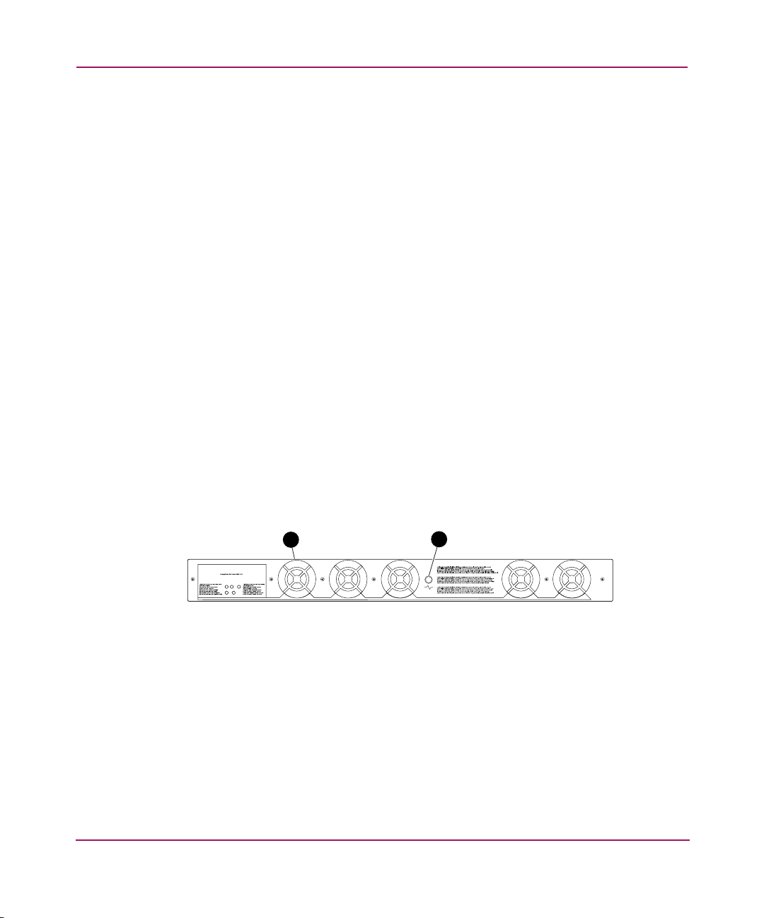
Figure 2 shows the fan side of the SAN Switch 2/8. The rear panel houses the five
fans, and port readiness LED.
Figure 2: Fan side
1 Fan (5)
2 Port readiness LED
SHR-2494B
2
1
Page 21

Overview
21hp StorageWorks SAN Switch 2/8 Installation Guide
Optional Hardware Kits
HP provides the following optional hardware kits in support of the SAN Switch
2/8, see Tab le 2.
* premerger HP part number
** premerger Compaq part number
Table 2: SAN Switch 2/8 Orderable Hardware
Accessory Part Number
Short wavelength SFP A6515A* or 300834-B21**
Long wavelength SFP, 10 km A6516A* or 300835-B21**
2m LC-to-LC Fibre Channel (fc) cable C7524A*
2m LC-to-LC multi-mode fc cable 221692-B21**
16m LC-to-LC fc cable C7525A*
5m LC-to-LC multi-mode fc cable 221692-B22**
50m LC-to-LC fc cable C7526A*
15m LC-to-LC multi-mode fc cable 221692-B23**
200m LC-to-LC fc cable C7527A*
30m LC-to-LC multi-mode fc cable 221692-B26**
50m LC-to-LC multi-mode fc cable 221692-B27**
2m LC-to-SC fc cable C7529A*
2m LC-to-SC multi-mode fc cable 221691-B21**
16m LC-to-SC fc cable C7530A*
5m LC-to-SC multi-mode fc cable 221691-B21**
15m LC-to-SC multi-mode fc cable 221691-B23**
30m LC-to-SC multi-mode fc cable 221691-B26**
50m LC-to-SC multi-mode fc cable 221691-B27**
SC female to SC female adapter C7534A*
2m LC male to SC male adapter kit C7534A*
Page 22

Overview
22 hp StorageWorks SAN Switch 2/8 Installation Guide
Page 23

23hp StorageWorks SAN Switch 2/8 Installation Guide
2
Installing the SAN Switch 2/8
This chapter covers the following topics:
■ Important Information about the Four Switch Limitation for 2/8 EL Models
Only, page 24
■ Unpack and Verify Carton Contents, page 28
■ Installation and Safety Guidelines, page 30
■ Installing the Switch as a Stand-alone Unit, page 32
■ Installing the SAN Switch 2/8 in a 9000 Series or Comparable EIA Rack,
page 33
■ Optional HP System/e Rack, page 36
■ Configuring SAN Switch 2/8 Network Addressing, page 47
■ Connecting the SAN Switch 2/8 to the LAN, page 50
■ Connecting a Cable to an SFP Module, page 55
■ Installing Multiple Switches into an Existing SAN, page 57
■ Cascading Switches, page 58
Page 24

Installing the SAN Switch 2/8
24 hp StorageWorks SAN Switch 2/8 Installation Guide
Important Information about the Four Switch Limitation for 2/8 EL Models Only
The SAN Switch 2/8 EL shipping configuration integrates the IV_Domain_Fabric
license. The IV_Domain_Fabric license limits the number of switches that can be
connected to a single fabric to four. If more than four switches (of any type) are
added to the fabric where 2/8 EL switches are installed, Web Tools generates
multiple error messages. Read the following sections for specific error messages
and workarounds related to the four switch limitation.
Note: Upgrade the 2/8 EL to full fabric support by installing an optional upgrade
license. See the “Four Switch Limitation Workarounds” section on page 27 for
instructions on how to purchase the Full Fabric license.
Check the License Installed
To verify the switch’s current license, use the command:
licenseshow
You do not have to delete the IV_Domain_Fabric license before upgrading to the
Full Fabric license.
Four Switch Limitation Errors
The following section summarizes the error messages generated when more than
four switches are installed in a fabric with the SAN Switch 2/8 EL.
Note: An operator can build a SAN with more than four switches by upgrading the
SAN Switch 2/8 EL to Full Fabric. To upgrade, you must install the optional Full Fabric
license on each SAN Switch 2/8 EL. See the “Four Switch Limitation Workarounds”
section on page page 27 for instructions on how to purchase the Full Fabric license.
Page 25
Installing the SAN Switch 2/8
25hp StorageWorks SAN Switch 2/8 Installation Guide
Four Switch Limitation CLI Error Messages
If the fabric detects that the four switch limitation has been exceeded, the
following message occurs every thirty seconds, via the Command Line Interface
(CLI), as follows:
CRITICAL FABRIC-SIZE_EXCEEDED, 1, Critical fabric size <8>
exceeds supported configuration <4>. Switch status marginal.
Contact Technical Support.
WebTools will be disabled in 39 days 8 hours and 46 minutes.
The switch warning messages may be stored in the Syslog. Third party application
SNMP traps may be configured on the switch.
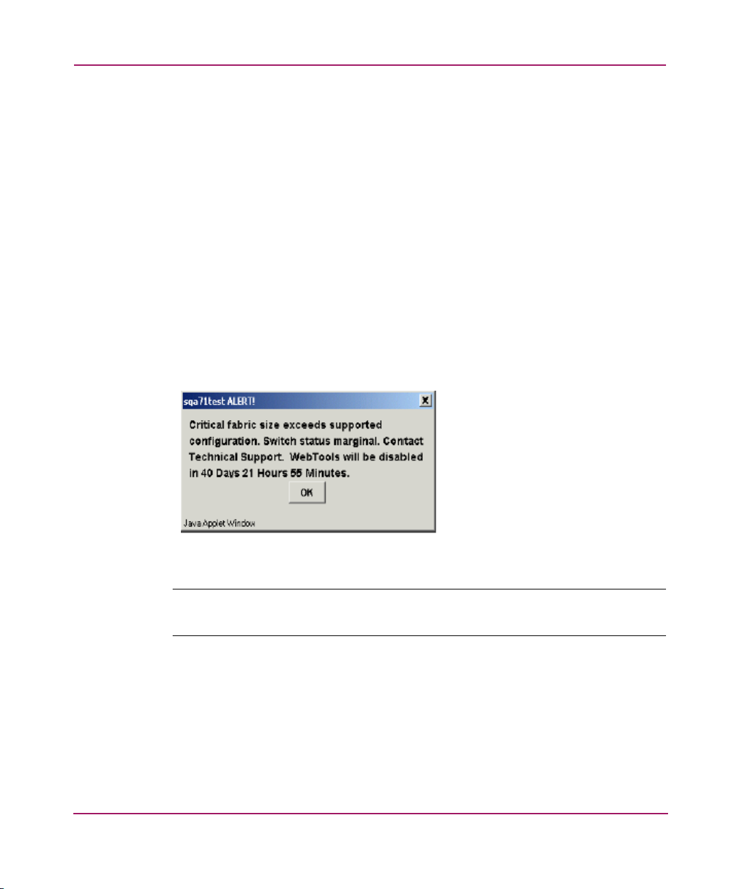
Four Switch Limitation Web Tools Error Messages
If the fabric detects that the number of switches installed exceeds the four switch
limit, Web Tools displays a warning message every 75 seconds (not configurable).
Figure 3 shows a typical Web Tools Warning Message.
Figure 3: Four switch limitation Web Tools error message
Note: The SAN Switch 2/8 EL displays a separate error condition warning message in
the dialog box.
Page 26
Installing the SAN Switch 2/8
26 hp StorageWorks SAN Switch 2/8 Installation Guide
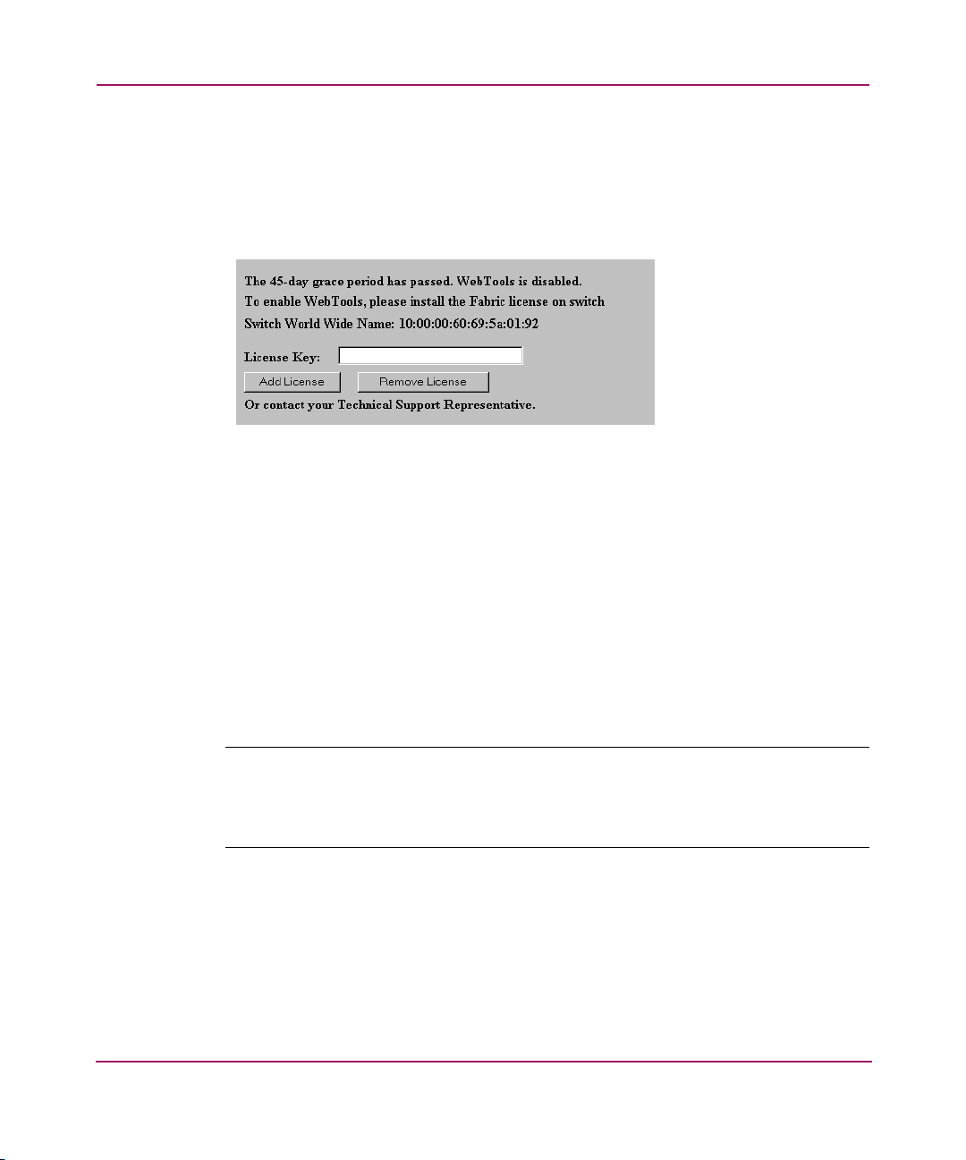
If the timer expires while trying to access Web Tools (for example, Zone Admin,
Switch Admin, or Switch View), an HTML file similar to license.htm appears,
stating that Web Tools is disabled. In addition, a prompt displays (see Figure 4)
allowing you to install the optional Fabric license. After the Full Fabric license is
installed, all Web Tools functionality resumes.
Figure 4: Full Fabric license install prompt in Web Tools
Violation Timer Errors
The violation timer begins decrementing when the four switch limitation is
exceeded. The timer is cumulative. Resetting the power cycle will not reset the
timer.
If the switch is moved to a fabric with less than five switches, the error condition
is cleared; however, the violation timer stops counting down. If the switch is
moved to a fabric with more than four switches, the violation timer continues from
where it left off. When the accumulative violation timer reaches 45 days (not
configurable), Web Tools for that switch is disabled. A message similar to
Figure 4 displays in a telnet session or error log.
Note: When Quiet Mode is enabled on a SAN Switch 2/8 EL with a IV_FABRIC
license installed, the four switch limitation warning messages display. If the IV_FABRIC
license is not installed, Quiet Mode works as described in the
hp StorageWorks Fabric
OS V3.0.x/V4.0.x
Reference Guide
.
Page 27

Installing the SAN Switch 2/8
27hp StorageWorks SAN Switch 2/8 Installation Guide
Additional Alerts
If the fabric size exceeds the four switch limit, the switch experiences the
following activity:
■ In Fabric Manager and Web Tools, the switch icons in Fabric View turn
yellow for every 2/8 EL installed in a fabric that exceeds the four switch limit.
For example, in Web Tools the following message appears in the bottom left
hand corner of the window:
The Fabric has changed - - Reload / Refresh
Note: To prevent this message from reappearing, you must update to the
optional
Full
Fabric license.
Please note that removing the Ethernet connection will not eliminate this
message. See the “Four Switch Limitation Workarounds” section on page 27 in this
chapter for instructions on how to purchase the Full Fabric license.
■ The switch beacons continuously, with front panel LEDs lighting amber,
similar to a firmware download. The switch stops beaconing during
reconfiguration, switchdisable, switchenable. It also stops beaconing when
the error condition no longer exists. Beaconing resumes if the error is detected
again.
Four Switch Limitation Workarounds
Use one of the following workarounds to prevent four switch limitation errors.
■ Upgrade the current SAN Switch 2/8 EL IV_Domain_Fabric license to the
optional Full Fabric license. The Full Fabric license provides full fabric
functionality, with no limits on the number of switches in the fabric.
For purchasing information, contact your authorized HP Sales representative,
or go to the HP website:
http://www .hp.com
■ In fabrics which contain five or more switches and that have at least one
switch with the IV_FABRIC license installed, reduce the number of switches
to four or less.
Page 28

Installing the SAN Switch 2/8
28 hp StorageWorks SAN Switch 2/8 Installation Guide
Unpack and Verify Carton Contents
Unpack and inspect the SAN Switch 2/8 carton contents as follows.
1. Inspect the shipping cartons for possible damage caused during transit.
2. Unpack the shipping cartons.
3. Verify that the carton contains the items shown in Figure 5 and Tab le 2. If any
items are damaged or missing, please contact HP or an HP authorized reseller.
Note: The Rack Mount Kit shown in Figure 5 may not represent the kit that shipped
with your switch. HP reserves the right to substitute Rack Mount Kits, providing
applicable instructions with each switch.
Figure 5: Carton contents
SHR-2495B
1
3
4
5
2
6
Page 29

Installing the SAN Switch 2/8
29hp StorageWorks SAN Switch 2/8 Installation Guide
* Depending on time of purchase, the Fixed Rack Mount Kit items listed in Table 3
may not represent the kit that shipped with your switch.
Table 3: Shipping Carton Contents
Item
Number
Description
1 One HP StorageWorks SAN Switch 2/8
product accessory bag containing CD,
license, documentation and Release
Notes
2HP StorageWorks Switch 2/8
3 Two standard AC power cords, and two
PDU cords
4 One RS-232 Serial cable
5 *Fixed Rack Mount Kit containing:
• right front bracket
• left front bracket
• right rear bracket
• left rear bracket
6 Pouch containing Fixed Rack Mount Kit
hardware:
• 8-32 x 5/16” pan head Phillips
screws (6)
• 6-32 x 5/16” pan head Phillips
screws (8)
• 10-32 x 3/8” pan head Phillips
screws (8)
•retainer nuts (8)
• rubber mounting feet (4), use if
installing on a flat surface
Page 30

Installing the SAN Switch 2/8
30 hp StorageWorks SAN Switch 2/8 Installation Guide
Installation and Safety Guidelines
Read the following sections for installation guidelines. Install the SAN Switch
2/8 in one of the following ways:
■ as a stand-alone unit on a flat surface, or
■ as a fixed component in the HP 9000 Series (or comparable) EIA Rack using
the Fixed Rack Mount Kit provided. Fixed Rack Mount Kit contents are
outlined in Tabl e 3.
■ as a fixed component in the HP System/e rack models
Selecting an Operating Location
To ensure correct operation of the switch, the location where the switch is in use
must meet the following requirements:
■ Adequate supply circuit, line fusing, and wire size, as specified by the
electrical rating on the switch nameplate.
■ An air flow of at least 300 cubic feet per minute, available in the immediate
vicinity of the switch.
■ If installing the switch in the HP 9000 Series, HP System/e, or comparable
Electronics Industries Association (EIA) rack:
— All equipment installed in the rack should have a reliable branch circuit
ground connection, and should not rely on a connection to a branch
circuit, such as a power strip.
— The rack should be balanced and the installed equipment within the rack’s
weight limits. Ensure the rack is mechanically secured to ensure stability
in the event of an earthquake.
Cooling Requirements
Caution: Do not block air vents. Blocking switch air vents may result in the switch
overheating.
Cooling air is drawn into the switch chassis by the fans mounted on the rear of the
chassis. The air is expelled through vents in the front of the chassis. HP
recommends installing the switch so that air intake and exhaust for all components
in the rack is flowing in the same direction.
Page 31

Installing the SAN Switch 2/8
31hp StorageWorks SAN Switch 2/8 Installation Guide
Power Requirements
One AC power cord connects to the switch. The AC power source must meet these
requirements:
■ A properly wired, earth-grounded AC outlet
■ Voltage capability of 85-264 VAC
■ Input voltage frequency of 47-63 Hz
■ Power capability of 75 watts, maximum
The switch uses a universal power supply capable of functioning worldwide
without voltage jumpers or switches. The power supply is auto ranging in terms of
accommodating input voltages and line frequencies.
Page 32

Installing the SAN Switch 2/8
32 hp StorageWorks SAN Switch 2/8 Installation Guide
Installing the Switch as a Stand-alone Unit
Use these procedures for setting up the switch as a stand-alone unit. The following
items are required for this setup:
■ SAN Switch 2/8
■ AC power cord and cables supplied with the switch
■ Rubber mounting feet supplied with the switch
1. Place the SAN Switch 2/8 on a flat, sturdy surface like a table or lab bench.
Caution: Installing the rubber feet on the switch is recommended to help
prevent the switch from accidentally sliding off the table or bench.
2. Apply the rubber feet as follows.
a. Clean the four depressions that are at each corner of the bottom of the
switch to ensure they are free of dust.
b. Place a rubber foot in each depression, with the adhesive side against the
chassis, and press into place.
3. Connect the power cable to the SAN Switch 2/8 power supply and to a power
outlet. Ensure the power cable is routed so that it is not exposed to stress.
4. Turn on the power to the switch (flip the AC switch to “1”). The switch
automatically runs a Power On Self-Test (POST).
Note: Do not connect the switch to the network until the IP address is correctly set. For
instructions on how to set the IP address, see the “Configuring SAN Switch 2/8
Network Addressing” section on page 47.
Page 33

Installing the SAN Switch 2/8
33hp StorageWorks SAN Switch 2/8 Installation Guide
Installing the SAN Switch 2/8 in a 9000 Series or Comparable EIA Rack
Read the following sections for complete installation instructions.
Obtain the following tools:
■ Fixed Rack Mount Kit (supplied with the switch)
■ A #2 Phillips screwdriver with torque capability
■ Clamps or other means to temporarily support the switch
■ Torque screwdriver
Caution: The SAN Switch 2/8 ships with the complete set of rack mount
hardware required for installation in an EIA rack. HP recommends using the
exact screws specified for use with the switch chassis. Using screws longer than
the specified length may damage the switch.
Installing the Fixed Rail Kit
The SAN Switch 2/8 Fixed Rack Mount Kit consists of two rail assemblies. Read
the following sections for complete instructions on attaching the rails to the
switch, then installing the switch in the rack.
1. Attach the left and right front brackets to the switch chassis as follows:
a. Position one left front bracket (Item 1) with the flat side against right side
of switch, oriented as shown in Figure 6.
Note: Four sets of holes are provided to allow the switch to be set back from the front of
the rack, if desired. This allows a more gradual bend in any fiber optic cables
connected to the switch.
b. Insert two 8-32 x 5/16 inch screws (Item 7) into one of the pairs of
vertically aligned holes in both the bracket and in the switch.
c. Insert one 8-32 x 5/16 inch screw (Item 7) into one of the single holes in
both the bracket and in the switch.
d. Tighten screws to a torque of 15-inch pounds.
Page 34

Installing the SAN Switch 2/8
34 hp StorageWorks SAN Switch 2/8 Installation Guide
2. Repeat steps 1a through 1d to attach right front bracket (Item 8) to the right
side of the switch, see Figure 6.
Figure 6: Attaching the Fixed Rack Mount Kit rails to the switch
3. Position the switch in the rack as shown in Figure 6, providing temporary
support under the switch (use clamps if necessary).
4. To secure the front brackets to the rack’s front rails, attach the right front
bracket (Item 8) to the right front rack rail using two 10-32 x 3/8 inch screws
(Item 5) and two retainer nuts (Item 6).
5. Repeat step 4 to attach the left front brackets (Item 1) to the left front rack rail.
6. Tighten all screws and torque to 25-inch pounds.
1 Left front bracket
2 Left rear bracket
3 6-32 x 5/16” pan head Phillips screws
4 Right rear bracket
5 10-32 x 38” pan head Phillips screws
6 Retainer nuts
7 6-32 x 5/16” pan head Phillips screws
8 Right front bracket
SHR-2501
A
3
5
4
2
6
7
8
1
Page 35

Installing the SAN Switch 2/8
35hp StorageWorks SAN Switch 2/8 Installation Guide
7. Attach the rear brackets to the front brackets as follows:
a. Position the right rear bracket (Item 4) inside the right front bracket (Item
8). See Figure 6.
b. Secure the brackets using four 6-32 x 5/16 inch screws (Item 3). See
Figure 6.
c. Adjust the brackets to the appropriate rack depth and tighten screws to a
torque of 9-inch pounds.
8. Repeat Steps 7a through 7c to attach the left rear bracket (Item 2) to the left
front bracket (Item 1).
9. Attach the right rear bracket (Item 4) to the right rear rack rail using two 10-32
x 3/8 inch screws (Item 5) and two retainer nuts (Item 6).
10. Repeat step 9 to attach the left rear bracket (Item 2) to the left rear rack rail.
11. Tighten all screws to a torque of 25-inch pounds.
12. Connect the SAN Switch 2/8 power cord to the power connector on the
switch. See Figure 7.
Figure 7: Connecting the power cord
SHR-2496B
Page 36

Installing the SAN Switch 2/8
36 hp StorageWorks SAN Switch 2/8 Installation Guide
Optional HP System/e Rack
This section lists instructions for installing the SAN Switch 2/8 in the optional HP
System/e Rack.
Items Required for the HP System/e Rack
The HP System/e Rack Kit consists of the following items:
■ HP System/e Rack Rail Kit, part number A7340-87901
■ Plenum, part number A7346-00001
■ HP System/e Rack Rail Kit Hardware, part number A7340-87902, shown
next:
(2) Rear mounting bracket
(8) #8-32 x 5/16 Phillips pan-head screw with captive star
lock washer
(8) #8 Flat washer
(6) M5 Torx head screw with captive lock washer
(2) Rubber washer
(4) M5 U-type tinnerman clip
Page 37

Installing the SAN Switch 2/8
37hp StorageWorks SAN Switch 2/8 Installation Guide
(4) #10-32 square Tinnerman nut (Use if installing in HP
9000 Series rack/ EIA rack)
(4) #10-32 x 5/8 Phillips pan-head screw with attached lock
washer (Use if installing in HP 9000 Series rack/ EIA rack))
(6) Spacer (Use if installing in HP 9000 Series rack/ EIA
rack)
(4) M5 flat washer ((Use if installing in HP 9000 Series
rack/ EIA rack)
Page 38

Installing the SAN Switch 2/8
38 hp StorageWorks SAN Switch 2/8 Installation Guide
Installing the Switch in the Optional HP System/e Rack
Before you begin, locate the following items to install the SAN Switch 2/8 in the
HP System/e Rack Kit:
■ SAN Switch 2/8
■ #2 Phillips and T25 Torx screwdrivers
Caution: F or proper airflow, the SFP media side of the SAN Switch 2/8 must
face the rear of the rack. This mounting allows air to enter the front of the rack
through the plenum and to exhaust at the rear of the rack, preventing
overheating.
1. Select a mounting location in the rack for the switch.
2. Attach the rear rail-tray brackets to the rear rack uprights by installing each of
the two mounting brackets with one M5 Torx head screw with captive lock
washer as shown in Figure 8.
Page 39

Installing the SAN Switch 2/8
39hp StorageWorks SAN Switch 2/8 Installation Guide
Figure 8: Installing the rear rail tray brackets
1 Rear rail tray bracket 2 M5 Torx head screw with
captive lock washer
SHR-255
7
1
2
Page 40

Installing the SAN Switch 2/8
40 hp StorageWorks SAN Switch 2/8 Installation Guide
3. Install two M5 U-type Tinnerman clips for each of the front columns of the
rack in the top and bottom positions of the three-hole EIA pattern as shown in
Figure 9.
Figure 9: Installing the tinnerman clips
4. Assemble the outer rails by completing the following steps:
a. As an aid in assembly, two rubber washers have been included to help
keep the rear slotted portion of the outer rail flush against the rear rail-tray
brackets. Install them as shown in Figure 10.
1 M5 U-type tinnerman clips 2 Upright rack post
SHR-25
5
1
2
Page 41

Installing the SAN Switch 2/8
41hp StorageWorks SAN Switch 2/8 Installation Guide
I
Figure 10: Installing the rubber washers
b. Insert the alignment pins attached to the outer rail front flange into the
center opening in the rack.
c. Install one M5 Torx screw in the upper hole location of the right rail.
Then, install one M5 Torx screw in the lower location of the left rail. See
Figure 11.
Note: Do not install the upper left and lower right screws until later.
1 Rubber washer (1 of 2) 2 Rear rail tray bracket (1 of 2)
[1] Select this graphic frame.
[2] Select File.
[3] Select Import.
[4] Select File.
[5] Choose the appropriate graphic file name.
[6] Make sure you’ve checked the Copy Into Document.
[7] Select Import. Position the illustration as required.
Delete this set of instructions
[8] Adjust the size of the outer graphic frame as required.
1
2
SHR-2559A
Page 42

Installing the SAN Switch 2/8
42 hp StorageWorks SAN Switch 2/8 Installation Guide
Figure 11: Assembling the outer rails
5. Assemble each of the two inner rails (one on each side of the switch and
plenum) using eight #8-32 x 5/16 Phillips pan-head screws (with attached star
lock washers) and eight #8 flat washers as shown in Figure 12.
Caution: Do not use any other screws other than the eight that are provided.
Use of any longer lengths can cause damage to internal components of the
switch. Be sure to install the flat washers along with the pan-head screws.
Before tightening screws, make sure that the rails are centered to the overall
height of the switch.
1 Outer rail alignment pins 2 M5 torx screws
1
2
SHR-2560A
Page 43

Installing the SAN Switch 2/8
43hp StorageWorks SAN Switch 2/8 Installation Guide
Figure 12: Assembling the inner rails
6. Insert the switch with the attached inner rails into the outer rails as shown in
Figure 13.
Note: Please note that the numbered items shown in Figure 12 must be ordered separately.
.
1 Plenum
2 8-32 x 5/16 phillips pan head screws
3 Flat washers
4 Inner rails (1 of 2)
1
2
3
4
SHR-2561A
Page 44

Installing the SAN Switch 2/8
44 hp StorageWorks SAN Switch 2/8 Installation Guide
Figure 13: Installing the switch into an HP Rack
7. Install the two remaining M5 Torx screws into the upper left and lower right
holes to complete the installation. See Figure 14.
SHR-2562A
Page 45

Installing the SAN Switch 2/8
45hp StorageWorks SAN Switch 2/8 Installation Guide
I.
Figure 14: Securing the switch
8. Connect the power cord to the switch power supply and to a power outlet.
Ensure the power cord is routed so that it is not exposed to stress. Power is
supplied to the switch as soon as the cord is connected. The switch runs POST
by default each time it is turned on.
Note: Do not connect the switch to the network until the IP address is correctly set. For
instructions on how to set the IP address, see “Configuring SAN Switch 2/8 Network
Addressing,” later in this chapter.
1 Outer slide rail (1 of 2) 2 Two M5 torx screws
[1] Select this graphic frame.
[2] Select File.
[3] Select Import.
[4] Select File.
[5] Choose the appropriate graphic file name.
[6] Make sure you’ve checked the Copy Into Document.
[7] Select Import. Position the illustration as required.
Delete this set of instructions
[8] Adjust the size of the outer graphic frame as required.
SHR-2563A
1
2
Page 46

Installing the SAN Switch 2/8
46 hp StorageWorks SAN Switch 2/8 Installation Guide
Power On Self-Test
Each time the switch is powered on, rebooted, or reset, the switch automatically
runs a Power On Self-Test (POST). During POST the port status LEDs flash,
verifying that the switch is operating properly. POST completes in approximately
six minutes, with total boot time approximately seven minutes.
POST runs through the following test cycles:
■ Preliminary POST diagnostics
■ Initialization of operating system
■ Initialization of hardware
■ Diagnostic tests are run on a number of functions, including circuitry, port
functionality, memory, parity, statistics counters, and serialization
For example, if the switch prompt does not display when POST completes, POST
was unsuccessful. Contact your authorized HP switch supplier for more
information.
To determine whether POST completed without errors, verify that all LEDs return
to a normal state after POST is complete. If one or more LEDs do not return to a
normal state (and this is not due to the switch being set to beacon), see
“Interpreting LED Activity” on page 60 in Chapter 3.
Note: For more information about beaconing, refer to the
hp StorageWorks Fabric OS
Procedures V3.0.x/V4.0.x User Guide
.
Checking POST Results
Check the success/fail results of the diagnostic tests run during POST via LED
activity, the error log, or the CLI using the errShow command. For more
information about error messages, refer to the hp StorageWorks Fabric OS
V3.0.x/V4.0.x Reference Guide.
Page 47

Installing the SAN Switch 2/8
47hp StorageWorks SAN Switch 2/8 Installation Guide
Configuring SAN Switch 2/8 Network Addressing
Read the following sections for information on how to configure the SAN Switch
2/8 addressing scheme.
Requirements
The following items are required to set network addressing.
■ An IP address from your Network Administrator
■ SAN Switch 2/8 installed and connected to a power source
■ Serial cable (supplied with the switch) for connecting the switch to the
workstation
■ A local workstation (desktop or notebook computer) with:
— Microsoft
® Windows 98, Windows 2000, Windows Millennium Edition,
or Windows NT 4.0 operating system
— RS-232 serial communication software (for example, ProComm Plus or
HyperTerminal)
■ Ethernet cable for connecting the switch to the workstation or to a network
containing the workstation
■ SFPs and cables, as required to connect the switch to the fabric
Setting Network Addresses via a Serial Connection
Use the following steps to verify or change the SAN Switch 2/8 IP address,
subnetmask, or gateway address.
Note: During first time setup, you must replace the factory IP, subnetmask and gateway
addresses with addresses provided by your Network Administrator.
1. Remove the shipping plug from the SAN Switch 2/8 Serial port.
Page 48

Installing the SAN Switch 2/8
48 hp StorageWorks SAN Switch 2/8 Installation Guide
2. Connect the Serial cable to the SAN Switch 2/8 Serial port, see Figure 15.
Figure 15: Connecting the Serial cable
3. Connect the other end of the Serial cable to an RS-232 Serial port on the
workstation. If no RS-232 Serial port is available on the workstation, the
adapter on the end of the Serial cable can be removed to use the RJ-45
connector to create a Serial connection.
4. Verify that the switch power is on and POST is completed. See the “Power On
Self-Test” section, on page page 46 in this chapter.
5. Power on the workstation and establish a connection to the switch using a
terminal emulator application (such as Hyperterminal).
Note: Step 6 shows instructions specific to HyperTerminal. If using a different
application, consult the specific application’s documentation.
6. Using Hyperterminal configure the port settings as follows:
■ Bits per second: 9600
■ Databits: 8
■ Parity: None
■ Stop bits: 1
■ Flow control: None
SHR-2497B
Page 49

Installing the SAN Switch 2/8
49hp StorageWorks SAN Switch 2/8 Installation Guide
To configure port settings in a UNIX® environment, type:
tip /dev/ttyb -9600
7. Log onto the switch (with administrative privileges). The default
administrative logon is admin and the default password is password.
a. Enter the following at the prompt:
ipAddrSet
b. Enter the following information at the corresponding prompts, listed
below:
— Ethernet IP Address [10.77.77.77]:
Enter the new Ethernet IP address.
— Ethernet subnetmask [0.0.0.0]:
Enter the new Ethernet subnetmask.
— Fibre Channel IP Address [none]:
Enter the new Fibre Channel IP address if desired.
— Fibre Channel subnetmask [none]:
Enter the new Fibre Channel subnetmask if desired.
— Gateway Address [172.17.1.1]:
Enter the new gateway address.
— Set IP address now? [y = set now, n = next
reboot]:
Enter y to set now.
c. To verify that the IP address was entered correctly, type:
ipAddrShow
d. Once the IP address is verified as correct, remove the Serial cable, and
replace the shipping plug in the Serial port.
Caution: The Serial port is intended only for use during the initial setting of
the IP address and for service purposes. Using the Serial port during normal
switch operation or for regular maintenance is not recommended.
8. Record the IP address on the label affixed to the SAN Switch 2/8 front panel.
Page 50

Installing the SAN Switch 2/8
50 hp StorageWorks SAN Switch 2/8 Installation Guide
Connecting the SAN Switch 2/8 to the LAN
Use the following steps to connect the SAN Switch 2/8 to the Ethernet Local Area
Network (LAN) segment.
1. Remove the shipping plug from the SAN Switch 2/8 Ethernet port.
2. Connect one end of an Ethernet cable to the Ethernet port, see Figure 16.
Figure 16: Connecting the Ethernet cable
3. Connect the other end of the Ethernet cable to the workstation or to an
Ethernet network containing the workstation.
Note: You can now access the switch remotely (and from multiple connections), using
telnet or the Web Tools application. Verify that the switch is not accessed from any other
connections during the remaining steps.
4. Log on to the switch with administrative privileges by telnet. The default
administrative logon is admin and the default password is password.
SHR-2498B
Page 51

Installing the SAN Switch 2/8
51hp StorageWorks SAN Switch 2/8 Installation Guide
Important Information on Setting the CORE PID Format
After connecting the SAN Switch 2/8 via Ethernet, you must verify that all
switches you intend to connect to the SAN use the same Core Port Identifier (PID)
format. A PID is one of two addressing mechanisms used in Fibre Channel. The
PID is analogous to specifying the physical switch and port a device is attached to
in data networks. It is not analogous to an IP address. PIDs are assigned by a Fibre
Channel switch when a device logs into the fabric.
An example PID might look like this:
011F00
In new installations, where both edge and Core switches reside, you must verify
that the edge switch (for example, SAN Switch 2/8) PID format matches the Core
switch’s PID format, before connecting to the SAN.
For example, switches with firmware V3.0.2f or later have the PID set to 1. For a
SAN to work correctly, all HP StorageWorks SAN switches or HP Surestore FC
switches must have the same PID format setting, either 0 or 1. If a switch is
introduced to an existing SAN with a setting that differs from the setting on the
SAN, the switch will segment.
How to Check the Current Core PID Setting
To determine a switch’s current Core PID format, connect directly to a switch in
your SAN and complete the following steps via a telnet session, or the serial cable
supplied with the switch.
Note: All switches in the SAN require the same PID format setting.
1. Type configShow and press Enter.
2. About 15 lines down (press Enter to display more information on the page),
locate the following line:
fabric.ops.mode.pidFormat:
3. Type switchDisable and press Enter.
4. Type configure and press Enter.
5. Type y at the Fabric parameters prompt, (yes, y, no, n): [no] y.
Page 52

Installing the SAN Switch 2/8
52 hp StorageWorks SAN Switch 2/8 Installation Guide
6. To view the Core Switch PID setting, press Enter until you reach the Core
Switch PID format line, similar to the following.
Core Switch PID Format: (0..1) [0]
Note: The [0] value shown above indicates the Core Switch PID parameter set on this
particular switch.
7. Continue to press Enter until the admin prompt displays.
8. Type switchEnable and press Enter.
If necessary, proceed to the next section to change the Core PID setting to match
all switches that will reside in the SAN.
How to Change the Core PID Format
Note: HP switches ship with the Core switch PID set to 1. HP recommends that if you
are in the process of creating a new SAN, set the PID to 1 for all switches in the SAN.
In order for the switches to interoperate properly, all of them must have the same
Core PID format. Use these steps to change the Core PID format, if necessary.
Caution: If you need to change the PID format on this new switch, change the
PID format before connecting the fiber cables.
1. If the switch is configured for zoning, type cfgDisable to disable zoning.
2. To disable the switch, type SwitchDisable.
3. To reset the PID format, use the “configure” telnet command. Type
configure. The following displays:
Configure...
4. Type y at the Fabric parameters prompt,
Fabric parameters (yes, y, no, n): [no] y
5. Locate the line, "Core Switch PID Format: (0..1) [0] 1," and type 1.
6. Press Enter until the following prompt appears.
Page 53

Installing the SAN Switch 2/8
53hp StorageWorks SAN Switch 2/8 Installation Guide
Committing configuration...Done
7. At the prompt type, SwitchEnable.
8. After setting the Core PID to match the the other switches in the fabric, go to
the “Connecting the SAN Switch 2/8 to the LAN” section on page 50 in this
chapter, for instructions on connecting Fibre Channel cables.
9. If necessary, type cfgEnable to re-establish zoning.
Note: Once the switch PID format is set, it is stored in the flash memory of the switch
and it is NOT necessary to set it again during subsequent firmware upgrades.
Modifying Domain IDs
Optional. Modify the domain IDs if desired, as follows.
Note: It is best to assign a unique domain ID prior to connecting the switch to other
switches in the SAN. This eliminates the possibility of domain ID overlap.The default
domain ID is 1. If the default domain ID is already in use when the switch is connected
to the fabric, the domain ID for the new switch is automatically reset to a unique value.
The domain IDs that are currently in use can be determined using the telnet command,
fabricShow.
1. To disable the switch, type:
switchDisable
2. Enter the following:
configure
Page 54

Installing the SAN Switch 2/8
54 hp StorageWorks SAN Switch 2/8 Installation Guide
3. Enter y after the Fabric Parameters prompt.
Fabric parameters (y, n)
4. Enter a unique domain ID (such as the domain ID used by the previous
switch, if still available).
Domain: (1..239) [1] 3
5. Complete the remaining prompts (or press CTRL+D to accept the remaining
settings without completing all the prompts).
6. Re-enable the switch, type:
switchEnable
Specifying Custom Status Policies
Optional. If desired, specify any custom status policies for the fabric as follows.
1. Enter the following at the prompt.
switchStatusPolicySet
2. Specify the desired status policies. To completely deactivate the alarm for a
particular condition, enter 0 at the prompt for that condition.
Page 55

Installing the SAN Switch 2/8
55hp StorageWorks SAN Switch 2/8 Installation Guide
Connecting a Cable to an SFP Module
Use these steps to connect the SFPs and cables to SAN Switch 2/8 ports as
required.
Note: The ports and cables used in trunking groups must meet specific requirements.
For a list of these requirements, refer to the
hp StorageWorks ISL Trunking
V3.0.x/V4.0.x
User Guide
.
1. Remove the shipping plugs from the appropriate ports.
2. Position the SFP so that the key (the tab near the cable-end of the SFP) is on
top.
3. Insert the SFP into the port until it is firmly seated and the latching
mechanism clicks.
Note: The SFP is keyed so that it can only be inserted with the correct orientation into
the port. If the SFP does not slide in easily, check the orientation.
Page 56

Installing the SAN Switch 2/8
56 hp StorageWorks SAN Switch 2/8 Installation Guide
4. Connect the cables to the SFPs as appropriate to the fabric topology, by
positioning each cable so that the key (the ridge on one side of the cable
connector) is aligned with the slot in the SFP. See Figure 17.
Figure 17: Inserting a cable into an SFP
Note: The cable is keyed so that it can only be inserted correctly into the SFP. If the
cable does not slide in easily, check the orientation.
Verifying Operation
After making the appropriate connections, as outlined in this chapter, use these
steps to verify that the switch is running properly.
1. Access your browser.
2. At the URL address window type, http://your switch IP
address.
3. Press Enter.
4. If connected properly, the name of your switch appears (in green) in the Web
browser window, indicating Healthy/OK.
SHR-2499B
Page 57

Installing the SAN Switch 2/8
57hp StorageWorks SAN Switch 2/8 Installation Guide
Note: HP strongly recommends backing up the configuration. This ensures that a
complete configuration is available if required for a replacement switch. For instructions
on how to back up the configuration, refer to “Backing Up System Configuration
Settings” on page 68 in Chapter 4.
Installing Multiple Switches into an Existing SAN
Use these steps to set up more than one SAN Switch 2/8 in an existing SAN.
1. Connect the appropriate components as outlined in the installation section of
this chapter.
2. Connect the Serial cable, provided in the carton contents, between a host
computer and the Serial port of the switch. See the “Setting Network
Addresses via a Serial Connection” on page 47 to make a serial connection
through a workstation and to set the IP address.
3. Connect the power cord to the AC connector on the switch. The switch
performs POST.
If a malfunction occurs during POST, error messages are written to the switch
error log and can be viewed by a telnet or terminal session when the POST
session completes.
If the malfunction prohibits the switch from completing the boot process (fatal
error), the switch stops the boot process. If the switch does not fully boot, the
switch prompt will not be displayed when the Serial port is connected.
4. Set the switch domain address using the configure command to the next
unused domain in the SAN. The default domain setting is 1.
Note: If a switch boot failure occurs, the switch must be taken offline for repair or
replacement. Contact your HP Technical Support for assistance.
5. Power off the new switch and connect one Fibre Channel cable from the SAN
to the new switch.
Page 58

Installing the SAN Switch 2/8
58 hp StorageWorks SAN Switch 2/8 Installation Guide
Cascading Switches
The domain id number uniquely identifies a switch in a fabric. Normally, the
switch automatically assigns the domain ID when a switch is first powered on or
when the switch disable/enable command is executed. When two switches
are cascaded together, there might be an initial domain ID conflict if the switches
had been assigned the same domain ID prior to being cascaded. This can be
avoided by changing the domain ID with the configure command.
The domain address may change when disabling and enabling one of the switches,
or rebooting one of the switches if the domain is not set using the configure
command. Switch parameters for all switches in a SAN must be the same, or the
switch may not join the SAN.
Page 59

59hp StorageWorks SAN Switch 2/8 Installation Guide
3
Managing the SAN Switch 2/8
This chapter covers the following topics:
■ Interpreting LED Activity, page 60
■ Management Overview, page 65
■ Running Basic Switch Operations Using Telnet, page 67
■ SAN Switch 2/8 Diagnostic Tests, page 70
Page 60

Managing the SAN Switch 2/8
60 hp StorageWorks SAN Switch 2/8 Installation Guide
Interpreting LED Activity
SAN Switch 2/8 activity and status can be determined through the activity of the
LEDs on the switch. The LEDs will flash green, yellow, or orange while the
switch is booting and while POST or other diagnostic tests are running. This is
normal and does not indicate a problem.
Note: Any errors related to LED activity are listed in the error log. For information
about the error log, refer to the
hp StorageWorks Fabric OS
V3.0.x/V4.0.x
Procedures
Guide
.
Front Panel LEDs
The SAN Switch 2/8 front panel includes the following LEDs:
■ One power switch LED on the front panel
■ One port status LED above and to the left of each of the 8 ports
■ One port speed LED above and to the right of each of the 8 ports
Tabl e 4 describes how front panel LEDs communicate switch status.
Page 61

Managing the SAN Switch 2/8
61hp StorageWorks SAN Switch 2/8 Installation Guide
Table 4: Front Panel LED Patterns During Normal Operation
LED
LED
Location
Color
Display
Hardware
Status
Recommended
Action
Switch Power
LED
To right of
Serial port
No light Switch is off, or
boot is not
complete, or
boot failed.
Verify switch is
on and has
completed
booting.
Steady green Switch is on. No action
required.
Slow-flashing
green
Error log
contains one or
more port
diagnostic error
messages.
1. Check port
status LEDs,
error log, port
media, and
cables or
loopback
plugs.
2. Clear error
log.
3. Rerun
diagnostics to
verify error
condition is
fixed.
Port Status LED Above
each port,
on left
No light No signal or light
carrier (media or
cable) detected.
Check media
and cable.
Steady green Port is online
(connected to
external device)
but shows no
traffic.
No action
required.
Slow-flashing
green
Port is online but
segmented,
indicating a
loopback cable
or incompatible
switch.
Verify correct
device is
connected to
port.
Page 62

Managing the SAN Switch 2/8
62 hp StorageWorks SAN Switch 2/8 Installation Guide
Port Status LED
(continued)
Above
each port,
on left
Fast-flashing
green
Port is in internal
loopback
(diagnostic).
No action
required.
Flickering
green
Port is online No action
required.
Steady
orange
Port is receiving
signal carrier, but
is not yet online.
No action
required.
Slow-flashing
orange
Port is disabled
(result of
diagnostics or
portDisable
command).
Enable port (via
the PortEnable
command; refer
to the hp
StorageWorks
Fabric OS
Reference.
Fast-flashing
orange
Port is faulty. 1. Check port
status LEDs,
error log, and
cable or
loopback
plug.
2. Clear error
log.
Flashing
green
Port is bypassed. Check
configuration of
Fibre Channel
loop.
Port Speed
LED
Above
each port,
on right
No light Port is
transmitting at
1 Gbps.
No action
required.
Steady green Port is
transmitting at
2 Gbps.
No action
required.
Table 4: Front Panel LED Patterns During Normal Operation (Continued)
LED
LED
Location
Color
Display
Hardware
Status
Recommended
Action
Page 63

Managing the SAN Switch 2/8
63hp StorageWorks SAN Switch 2/8 Installation Guide
Ethernet Link
Speed LED
Two Left
LEDs near
Ethernet
port
No light Port is
transmitting at
10 Mbps.
No action
required.
Steady green Port is
transmitting and
receiving at 100
Mbps.
No action
required.
Ethernet Link
Activity LED
Two Right
LEDs near
Ethernet
port
No light No Ethernet
traffic is flowing
through the
RJ-45 port.
Verify switch is
powered on, and
Ethernet cable is
firmly seated.
Flickering
green
Ethernet traffic is
flowing through
the RJ-45 port.
No action
required.
Table 4: Front Panel LED Patterns During Normal Operation (Continued)
LED
LED
Location
Color
Display
Hardware
Status
Recommended
Action
Page 64

Managing the SAN Switch 2/8
64 hp StorageWorks SAN Switch 2/8 Installation Guide
Rear Panel LED
The SAN Switch 2/8 rear panel includes one port readiness LED. Tabl e 5
describes how rear panel LEDs communicate switch status.
Table 5: Rear Panel LED Patterns During Normal Operation
LED
LED
Location
Color
Display
Hardware
Status
Recommended
Action
Port Readiness
LED
Center of
back panel
No light Switch is off, or
boot is not
complete, or
boot failed.
Verify switch is
on and has
completed
booting.
Steady green Switch is on and
all ports are
ready for use.
No action
required.
Steady
yellow
One or more
ports are offline.
Verify switch has
completed
booting and is
not disabled. If
light is still
yellow, check
error log and
Port Status
LEDs.
Slow-flashing
yellow
Error log
contains one or
more port
diagnostic error
messages.
1. Check error
log, Port
Status LEDs,
port media,
and cables or
loopback
plugs.
2. Clear error
log.
3. Rerun
diagnostics to
verify error
condition is
fixed.
Page 65

Managing the SAN Switch 2/8
65hp StorageWorks SAN Switch 2/8 Installation Guide
Management Overview
The SAN Switch 2/8 can be managed using TCP/IP protocol, in-band over Fibre
Channel, or out-of-band by connecting to the Ethernet port. The management
functions allow the administrator to monitor fabric topology, port status, physical
status, and other information to aid in system debugging and performance
analysis.
The SAN Switch 2/8 is compatible with the following management interfaces:
■ CLI via a telnet or serial connection—For more information refer to the hp
StorageWorks Fabric OS V3.0.x/V4.0.x Procedures Guide, and the hp
StorageWorks
Fabric OS V3.0.x/V4.0.x Reference Guide.
■ Standard SNMP applications—For more information refer to the hp
StorageWorks MIB V3.0.x/V4.0.x Reference Guide.
■ Web Tools—Provides an easy-to-use GUI, allowing the SAN administrator to
monitor and manage entire fabrics and individual switches and ports from a standard
workstation.
Provides you with the advantage of being “virtually” in front of
any fabric, switch, or port. For more information refer to the hp StorageWorks
Web Tools V3.0.x/V4.0.x User Guide.
Note: The HP StorageWorks SAN Switch 2/8 EL and HP StorageWorks SAN Switch
2/8 Power Pak models offer a different set of integrated features, depending on the
model purchased. Please refer to the
hp StorageWorks SAN Switch 2/8 Version
3.0.2k Release Notes for a complete list of management features enabled on your
specific switch.
Page 66

Managing the SAN Switch 2/8
66 hp StorageWorks SAN Switch 2/8 Installation Guide
Displaying the Optional Feature Licenses
Use these steps to display optional features installed on your switch.
1. Log in to the switch as the admin user.
2. At the command line type,
licenseShow
This command displays the license keys that have been entered for the switch
and the features enabled by those licenses.
Enabling Licensed Features
Licensed features such as QuickLoop and Fabric Watch are already loaded onto
the switch firmware, but must be enabled with a license key. Once you have
purchased these features you are provided with a key to unlock the feature.
Use these steps to enable a licensed feature.
1. Log in to the switch as the admin user.
2. At the command line enter the following command:
licenseAdd aaaBbbCcc
(where aaaBbbCcc is the license key for a particular feature.)
Note: You must enter a license key for each feature to activate. License keys are case
sensitive.
Page 67

Managing the SAN Switch 2/8
67hp StorageWorks SAN Switch 2/8 Installation Guide
Running Basic Switch Operations Using Telnet
Read the following sections to run common switch operations.
Logging into the SAN Switch 2/8
Use these steps to log into the SAN Switch 2/8.
1. Open a telnet connection to the switch. The login prompt is displayed if the
telnet connection successfully found the switch in the network.
Note: The switch must be connected to your IP network through the Ethernet port to
enable connection using telnet.
2. At the login prompt enter the user ID you are logging in as. For example:
login: admin
The password prompt is displayed if the user exists.
3. Enter the password for the user:
password: xxxxxx
The default password is password.
4. If the login was successful a prompt is displayed showing the switch name
and user ID you are logged in as. For example:
switch55>admin:
Changing the Admin Password and User ID
Use these steps to change the Admin user ID and password.
Note: For security reasons, the first time you log into the Fabric OS you are requested
to change the admin user ID and system password.
1. Log in to the switch as the admin user.
2. At the command line enter the following command:
Password admin
Page 68

Managing the SAN Switch 2/8
68 hp StorageWorks SAN Switch 2/8 Installation Guide
An interactive session is opened and you are prompted for configuration
values.
3. At the New Username prompt, enter a new name for the admin user. You
can change the name of the admin user without changing the password. Press
Enter to leave the name as is.
4. At the Old Password prompt, enter the old password.
5. At the New Password prompt, enter the new password. The new password
must be from 8 to 40 characters in length.
6. At the New Password prompt, enter the new password exactly as entered to
the previous prompt.
7. Press Enter to commit the configuration to the firmware.
Configuring the IP and Fibre Channel Address
The SAN Switch 2/8 is shipped with a default IP address of 10.77.77.77. Use
these steps to change the default IP Address and configure the Fibre Channel IP
address of the switch.
1. Log in to the switch as the admin user.
2. At the command line enter the following command:
ipAddrSet
An interactive session is opened and you are prompted for configuration
values. Press Enter to skip over a prompt and leave the parameter value as is.
3. At the Ethernet IP Address prompt, enter the new IP address for the Ethernet
port on the switch. Press Enter to continue.
4. At the subnetmask prompt, enter the address of the subnetmask, if applicable.
Press Enter to continue.
5. At the Fibre Channel IP address prompt, enter the Fibre Channel IP address
for the switch. Press Enter to continue.
6. At the Fibre Channel subnetmask prompt, enter the address of the
subnetmask, if applicable. Press Enter to continue.
7. At the gateway address prompt, enter the IP address of the gateway system if
applicable. Press Enter to continue.
The configuration is committed to the switch firmware.
8. Enter y at the prompt to have the IP address changes take effect immediately.
Page 69

Managing the SAN Switch 2/8
69hp StorageWorks SAN Switch 2/8 Installation Guide
Displaying Devices within the Fabric
To verify that you have fabric-wide connectivity when you install a new switch,
display the fabric-wide Fibre Channel address list from the newly installed switch.
Use these steps to display the fabric.
1. Log in to the switch as the admin user.
2. At the command line enter the following command:
nsAllShow
This command displays a list of Fibre Channel addresses for all devices in the
fabric.
Checking the Firmware Version
Use these steps to display the SAN Switch 2/8 firmware version.
1. Log in to the switch as the admin user.
2. At the command line enter the following command:
version
This command displays the Kernel version, and Fabric OS release number.
Setting the Switch Date and Time
All switches maintain current date and time in non-volatile memory. Date and
time are used for logging events. Switch operation does not depend on the date
and time; a switch with an incorrect date and time value still functions properly.
Use these steps to set the date and time of a switch.
1. Log in to the switch as the admin user.
2. At the command line enter the following command:
date MMDDhhmmYY
where:
— MM is the month, valid values are 01-12
— DD is the date, valid values are 01-31
— hh is the hour, valid values are 00-23
— mm is minutes, valid values are 00-59
— YY is the year, valid values are 00-99
Page 70

Managing the SAN Switch 2/8
70 hp StorageWorks SAN Switch 2/8 Installation Guide
Note: Year values greater than 69 are interpreted as 1970-1999, year values less than
70 are interpreted as 2000-2069. The date function does not support daylight saving
time or time zones.
Displaying Switch Configuration Settings
Use these steps to display the system configuration settings.
1. Log in to the switch as the admin user.
2. At the command line enter the following command:
configShow
The system configuration settings are displayed.
SAN Switch 2/8 Diagnostic Tests
Read the following sections for information on using POST and diagnostic tests.
Interpreting POST Results
Each time the switch is powered on or reset, the switch automatically performs
POST, a one minute system check during which the port status LEDs flash
different colors.
To determine whether POST completed without errors, verify that all LEDs return
to a normal state after POST is complete. If one or more LEDs do not return to a
normal state, and this is not due to the switch being set to beacon, refer to the hp
StorageWorks Fabric OS V3.0.x/V4.0.x Procedures User Guide.
Note: If the switch prompt does not display when POST completes, POST was not
successfully completed and the switch should be returned to your switch supplier for
repair.
Any errors detected during POST are written to the system log, accessible through
the errShow command. For more information about error messages, refer to the
hp StorageWorks Fabric OS V3.0.x/V4.0.x Procedures User Guide.
Page 71

Managing the SAN Switch 2/8
71hp StorageWorks SAN Switch 2/8 Installation Guide
Diagnostic Tests
Diagnostic tests help troubleshoot the hardware and the firmware. The diagnostic
tests provided on the switch include tests of internal connections and circuitry,
fixed media, and any SFP modules and fiber optic cables in use. The tests are
implemented by command, either through a telnet session or through a terminal
set up for a serial connection to the switch. Some tests require the ports to be
connected by external cables, to allow diagnostics to verify the
serializer/deserializer interface, as well as the attached SFP and cable.
All diagnostic tests are run at link speeds of both 1 Gbps and 2 Gbps. For
information about the specific diagnostic tests and how to run them, refer to the hp
StorageWorks Fabric OS V3.0.x/V4.0.x Procedures User Guide.
Note: The transmit and receive speed of the links may be temporarily locked to a
specific speed during diagnostic testing.
Page 72

Managing the SAN Switch 2/8
72 hp StorageWorks SAN Switch 2/8 Installation Guide
Page 73

73hp StorageWorks SAN Switch 2/8 Installation Guide
4
Saving Configuration Settings and Upgrading Firmware
This chapter provides the following information:
■ Backing Up System Configuration Settings, page 74
■ Upgrading or Restoring the Switch Firmware, page 76
■ Downloading Firmware from the HP Website, page 76
Page 74

Saving Configuration Settings and Upgrading Firmware
74 hp StorageWorks SAN Switch 2/8 Installation Guide
Backing Up System Configuration Settings
HP strongly recommends saving the configuration after the initial configuration
changes and periodically thereafter.
FTP must be used on Windows workstations to back up the system configuration.
The FTP server must be running before an upload can occur. Use the RSHD
service or FTP on a UNIX machine.
Note: The two supplied utilities,
RSHD.EXE
and
CAT.EXE
currently do not support
uploads for Windows, only downloads. These utilities are available from the support
website:
http://www.hp.com/support
.
Use these steps to upload a backup copy of the configuration settings to a host
computer.
1. Verify that the RSHD service (on a UNIX machine) or the FTP service (on a
Windows or UNIX machine) is running on the host workstation.
2. Log in to the switch as the admin user.
3. At the command line enter the following command:
configUpload hostIPaddr, user path_filename password
For example, hostIPaddr is the IP address of the host computer, user is the
User ID used to log into this computer, path_filename is the path location and
filename of the configuration file, and password is the password for the user
ID specified.
If only configupload is entered, the system prompts you for each
parameter, as follows:
Example:
switch:admin> configupload
Server Name or IP Address [host]: 123.45.678.901
User Name [user]: kelev
File Name [config.txt]: switch1
Protocol (RSHD or FTP) [rshd]: ftp
Password:
upload complete
Page 75

Saving Configuration Settings and Upgrading Firmware
75hp StorageWorks SAN Switch 2/8 Installation Guide
Restoring the System Configuration Settings
Use these steps to restore the system configuration settings from a backup.
1. Verify that the RSHD service or the FTP service is running on the host
workstation.
2. Log in to the switch as the admin user.
3. Shut down the switch by entering the following command:
switchDisable
4. At the command line enter the following command:
configDownload hostIPaddr, user, path_filename,password
For example, hostIPaddr is the IP address of the host computer, user is
the User ID used to log into this computer, path_filename is the path
location and filename of the system configuration file, and password is the
password for the user ID specified.
Note: The password operand is only required if you are using FTP.
5. Reboot the switch by entering the following command:
fastBoot
Page 76

Saving Configuration Settings and Upgrading Firmware
76 hp StorageWorks SAN Switch 2/8 Installation Guide
Upgrading or Restoring the Switch Firmware
The SAN Switch 2/8 ships with preloaded firmware. In most cases there is no
need to update the firmware on the new switch. The firmware version can be
determined by using:
■ The version Telnet command
■ The Switch Management Application page in Web Management Tools
Use these steps to upgrade or restore the switch firmware.
1. Verify that the RSHD service or the FTP service is running on the host
workstation.
2. Login to the switch as the admin user.
3. At the command line, type:
firmwareDownload hostIPaddr, user, path_filename, password
For example, where hostIPaddr is the IP address of the host computer,
user is the User ID used to log into this computer, path_filename is the
path location and filename of the new firmware file, and password is the
password for the user ID specified.
Note: The password operand is only required if you are using FTP.
4. Reboot the switch by entering the following command:
fastBoot
Downloading Firmware from the HP Website
To download the firmware from the HP website, go to
http://www.hp.com/support
. The website contains the required loaders and
instructions for downloading the firmware to a switch.
Page 77

77hp StorageWorks SAN Switch 2/8 Installation Guide
A
Regulatory Compliance Notices
FCC EMC Statement (USA)
This equipment has been tested and found to comply with the limits for a Class A
digital device, pursuant to Part 15 of the FCC Rules. These limits are designed to
provide reasonable protection against harmful interference when the equipment is
operated in a commercial environment. This equipment generates, uses and can
radiate radio frequency energy and, if not installed and used in accordance with
the instruction manual, may cause harmful interference to radio communications.
Operation of this equipment in a residential area is likely to cause harmful
interference, in which case the user will be required to correct the interference at
his own expense. The end user of this product should be aware that any changes or
modifications made to this equipment without the approval of Hewlett-Packard
could result in the product not meeting the Class A limits, in which case the FCC
could void the user's authority to operate the equipment.
Page 78

Regulatory Compliance Notices
78 hp StorageWorks SAN Switch 2/8 Installation Guide
EMC Statement (Canada)
This Class A digital apparatus meets all requirements of the Canadian
Interference-Causing Equipment Regulations.
Cet appareil numérique de la Classe A respecte toutes les exigences du Règlement
sur le matériel brouilleur du Canada.
EMC Statement (European Union)
This is a Class A product. In a domestic environment this product may cause radio
interference, in which case the user may be required to take adequate measures.
Spécification ATI Classe A (France)
DECLARATION D'INSTALLATION ET DE MISE EN EXPLOITATION d'un
matériel de traitement de l'information (ATI), classé A en fonction des niveaux de
perturbations radioélectriques émis, définis dans la norme européenne EN 55022
concernant la Compatibilité Electromagnétique.
Germany Noise Declaration
Schalldruckpegel Lp = 46.1 dB(A)Am Arbeitsplatz (operator position) Normaler
Betrieb (normal operation)Nach ISO 7779:1999 (Typprüfung)
VCCI EMC Statement (Japan)
Page 79

Regulatory Compliance Notices
79hp StorageWorks SAN Switch 2/8 Installation Guide
Harmonics Conformance (Japan)
BSMI EMC Statement (Taiwan)
RRL EMC Statement (Korea)
Page 80

Regulatory Compliance Notices
80 hp StorageWorks SAN Switch 2/8 Installation Guide
Laser Safety
A. Certification and Classification Information
When equipped with native Fibre Channel adapters, this product contains a laser
internal to the small form factor pluggable (SFP) transceiver modules.
In the USA, the SFP module is certified as a Class 1 Laser product, conforming to
the requirements contained in Department Of Health and Human Services
(DHHS) regulation 21 CFR, Subchapter J. The certification is indicated by a label
on the metal SFP housing.
Outside the USA, the SFP is certified as a Class 1 Laser product conforming to
requirements contained in IEC 825-1:1993 and EN60825-1:1994, including
Amendment 11:1996.
The SFP includes the following certifications:
■ UL Recognized Component (USA)
■ CSA Certified Component (Canada)
■ TUV Certified Component (European Union)
■ CB Certificate (Worldwide)
The following figure shows the Class 1 information label that appears on the metal
housing of the SFP.
B. Product Information
Each communications port consists of a transmitter and receiver optical
subassembly. The transmitter subassembly contains internally a semiconductor
laser diode in the wavelength of either 850 nanometers (shortwave laser) or 1310
nanometers (longwave laser).
Class 1 Laser products are not considered hazardous.
C. Usage Restrictions
Failure to comply with these usage restrictions may result in incorrect operation of
the system and points of access may emit laser radiation above the Class 1 limits
established by the IEC and U.S. DHHS.
CLASS 1 LASER PRODUCT 21 CFR(J)
Page 81

Regulatory Compliance Notices
81hp StorageWorks SAN Switch 2/8 Installation Guide
Battery Replacement Notice
Your switch is equipped with a lithium manganese dioxide, a vanadium pentoxide,
or an alkaline internal battery or battery pack. There is a danger of explosion and
risk of personal injury if the battery is incorrectly replaced or mistreated.
Replacement is to be done by an HP authorized service provider using the HP
spare designated for this product. For more information about battery replacement
or proper disposal, contact your HP authorized reseller or your authorized service
provider.
WARNING: Your switch contains an internal lithium manganese dioxide, a
vanadium pentoxide, or an alkaline battery. There is risk of fire and burns if
the battery is not handled properly. To reduce the risk of personal injury:
— Do not attempt to recharge the battery.
— Do not expose to temperatures higher than 140°F (60°C).
— Do not disassemble, crush, puncture, short external contacts, or
dispose of in fire or water.
Batteries, battery packs, and accumulators should not be disposed of with the
general household waste. In order to forward them to recycling or proper disposal,
please use the public collection system or return them to HP, your authorized HP
partners, or their agents.
Page 82

Regulatory Compliance Notices
82 hp StorageWorks SAN Switch 2/8 Installation Guide
Page 83

83hp StorageWorks SAN Switch 2/8 Installation Guide
B
Electrostatic Discharge
To prevent damaging the system, be aware of the precautions you need to follow
when setting up the system or handling parts. A discharge of static electricity from
a finger or other conductor may damage system boards or other static-sensitive
devices. This type of damage may reduce the life expectancy of the device.
To prevent electrostatic damage, observe the following precautions:
■ Avoid hand contact by transporting and storing products in static-safe
containers.
■ Keep electrostatic-sensitive parts in their containers until they arrive at
static-free workstations.
■ Place parts on a grounded surface before removing them from their
containers.
■ Avoid touching pins, leads, or circuitry.
■ Always make sure you are properly grounded when touching a static-sensitive
component or assembly.
Page 84

Electrostatic Discharge
84 hp StorageWorks SAN Switch 2/8 Installation Guide
Grounding Methods
There are several methods for grounding. Use one or more of the following
methods when handling or installing electrostatic-sensitive parts:
■ Use a wrist strap connected by a ground cord to a grounded workstation or
computer chassis. Wrist straps are flexible straps with a minimum of 1
megohm ± 10 percent resistance in the ground cords. To provide proper
ground, wear the strap snug against the skin.
■ Use heel straps, toe straps, or boot straps at standing workstations. Wear the
straps on both feet when standing on conductive floors or dissipating floor
mats.
■ Use conductive field service tools.
■ Use a portable field service kit with a folding static-dissipating work mat.
If you do not have any of the suggested equipment for proper grounding, have an
HP authorized reseller install the part.
Page 85

85hp StorageWorks SAN Switch 2/8 Installation Guide
C
Technical Specifications
This appendix covers the following topics:
■ Dimensions
■ Power supply specifications
■ Environmental specifications
■ Memory specifications
■ Serial port specifications
Page 86

Technical Specifications
86 hp StorageWorks SAN Switch 2/8 Installation Guide
Dimensions
Tabl e 6 lists SAN Switch 2/8 dimensions.
Power Supply Specifications
Tabl e 7 lists power supply specifications. The power supply is universal and
capable of functioning worldwide without using voltage jumpers or switches. It
meets IEC 61000-4-5 surge voltage requirements The power supply has its own
built-in fan for cooling, pushing the air towards the front of the switch.
Table 6: Physical Specifications
Dimension Value
Height 1.71 inches (4.34 cm)
Depth 10.4 inches (26.4 cm)
Width 16.9 inches (42.8 cm)
Weight (with both power supplies) 8.5 lbs (3.9 kg)
Table 7: Power Supply Specifications
Specification Value
Outlet Correctly wired and earth-grounded
Total power available from each
power supply
75 watts
Max. switch power 50 watts
Input voltage 90 - 264 VAC
Input line frequency 47 - 63 Hz
Harmonic distortion Active power factor correction per
IEC1000-3-2
BTU rating 70 Watts x 3.412 BTU/Hr/Watts = 239
BTU/hr
Inrush current 40 Amps Peak, cold start at 25 degrees
Celsius
Input line protection Fused in both hot & neutral lines
Page 87

Technical Specifications
87hp StorageWorks SAN Switch 2/8 Installation Guide
Environmental Requirements
Table 7 lists the environmental ranges that are acceptable when the SAN Switch
EL is operating, and the acceptable ranges when the switch is not operating.
Memory Specifications
The SAN Switch 2/8 uses the following memory.
■ Main Memory (SDRAM): 32 MB per switch
■ Flash Memory: Dual 8 MB
■ Boot Flash: 512K bytes of 8-bit for system boot
The centralized memory maximizes the overall switch throughput by guaranteeing
full transmit and receive bandwidth to all Fibre Channel ports at all times.
Table 8: Environmental Requirements
Condition Acceptable Range
Temperature (operating) 10°C to 40°C
Temperature (non-operating) -25°C to 70°C
Humidity (operating) 20% to 85% RH non condensing, at
40°C
Humidity (non-operating) 0% to 90% RH non-conducting, at 40°C
Altitude (operating) 0 to 3 kilometers above sea level
Altitude (non-operating) 0 to 12 kilometers above sea level
Shock (operating) 4G, 11MS duration, half sine
Shock (non-operating) 20G, 11MS duration, sq.wave
Vibration (operating) 5G, 0-3 kHz at 1.0 octave/minute
Vibration (non-operating) 10G, 0-5kHz at 1.0 octave/minute
Page 88

Technical Specifications
88 hp StorageWorks SAN Switch 2/8 Installation Guide
Serial Port Specifications
The Serial port can be used to connect to a computer workstation to configure the
switch IP address without connecting to the fabric. The Serial port’s parameters
are 9600 baud, 8 data bits, no parity, 1 stop bit, and no flow control.
The port requires a straight serial cable with a female 9-pin subminiature-D
connector. Only pins 2, 3, and 5 are supported; if pin 7 is used, the signal must
always be driven high, using the pinouts listed in Tab le 9.
Note: For dust and ESD (electrostatic discharge) protection, a cover is provided for the
serial port and should be kept on the port whenever the serial port is not in use.
Table 9: Cabling Pinouts if Pin 7 is Used
PIN Signal Description
1
2 TxData Transmit Data
3 RxData Receive Data
4
5 GND Logic Ground
6
7 CTS Clear to Send
8
9
Page 89

89hp StorageWorks SAN Switch 2/8 Installation Guide
glossary
Glossary
Glossary
This glossary defines terms used in this guide or related to this product and is not
a comprehensive glossary of computer terms.
AL_PA
Arbitrated Loop Physical Address; a unique 8-bit value assigned during loop initialization to a
port in an arbitrated loop.
Alias Address Identifier
An address identifier recognized by a port in addition to its standard identifier. An alias
address identifier may be shared by multiple ports.
Alias AL_PA
An AL_PA value recognized by an L_Port in addition to the AL_PA assigned to the port.
Alias Server
A fabric software facility that supports multicast group management.
API
Application Programming Interface; defined protocol that allows applications to interface
with a set of services.
Arbitrated Loop
A shared 100 MBps or 200 MBps Fibre Channel transport structured as a loop. Can support
up to 126 devices and one fabric attachment. See also To po log y.
ASIC
Application Specific Integrated Circuit.
ATM
Asynchronous Transfer Mode; a transport used for transmitting data over LANs or WANs that
transmit fixed-length units of data. Provides any-to-any connectivity, and allows nodes to
transmit simultaneously.
Page 90

Glossary
90 hp StorageWorks SAN Switch 2/8 Installation Guide
AW_TOV
Arbitration Wait Time-out Value; the minimum time an arbitrating L_Port waits for a response
before beginning loop initialization.
Bandwidth
The total transmission capacity of a cable, link, or system. Usually measured in bps (bits per
second). May also refer to the range of transmission frequencies available to a network. See
also Throughput.
BB_Credit
Buffer-to-buffer credit; the number of frames that can be transmitted to a directly connected
recipient or within an arbitrated loop. Determined by the number of receive buffers available.
BER
Bit Error Rate; the rate at which bits are expected to be received in error. Expressed as the
ratio of error bits to total bits transmitted. See also Error.
Block
As applies to Fibre Channel, upper-level application data that is transferred in a single
sequence.
Bridge
Hardware that connects incompatible networks by providing translation for both hardware and
software. For example, an ATM gateway can connect a Fibre Channel link to an ATM
connection.
Broadcast
The transmission of data from a single source to all devices in the fabric, regardless of zoning.
Buffer-to-buffer Flow Control
Management of the frame transmission rate in either a point-to-point topology or in an
arbitrated loop. See also BB_Credit.
Cascade
Two or more interconnected Fibre Channel switches. The recommended number of
interswitch links is seven. See also Fabric, ISL.
Chassis
The metal frame in which the switch and switch components are mounted.
Circuit
An established communication path between two ports. Consists of two virtual circuits
capable of transmitting in opposite directions. See also Link.
Page 91

Glossary
91hp StorageWorks SAN Switch 2/8 Installation Guide
Command Line
Interface that depends entirely on the use of commands, such as through telnet or SNMP, and
does not involve a GUI.
Community (SNMP)
A relationship between a group of SNMP managers and an SNMP agent, in which
authentication, access control, and proxy characteristics are defined. See also SNMP.
Connection Initiator
A port that has originated a Class 1 dedicated connection and received a response from the
recipient.
Connection Recipient
A port that has received a Class 1 dedicated connection request and transmitted a response to
the originator.
CRC
Cyclic Redundancy Check; a check for transmission errors included in every data frame.
Credit
As applies to Fibre Channel, the number of receive buffers available for transmission of
frames between ports. See also BB_Credit, EE_Credit.
Disparity
The relationship of ones and zeros in an encoded character. “Neutral disparity” means an
equal number of each, “positive disparity” means a majority of ones, and “negative disparity”
means a majority of zeros.
DLS
Dynamic Load Sharing; dynamic distribution of traffic over available paths. Allows for
recomputing of routes when an Fx_Port or E_Port changes status.
Domain ID
As applies to SAN switches, a unique number between 1 and 239 that identifies the switch to
the fabric and is used in routing frames. Usually automatically assigned by the switch, but can
be manually assigned.
E_D_TOV
Error Detect Time-out Value; the minimum amount of time a target waits for a sequence to
complete before initiating recovery. Can also be defined as the maximum time allowed for a
round-trip transmission before an error condition is declared.
Page 92

Glossary
92 hp StorageWorks SAN Switch 2/8 Installation Guide
E_Port
Expansion Port; a type of switch port that can be connected to an E_Port on another switch to
create an ISL. See also ISL.
EE_Credit
End-to-end Credit; the number of receive buffers allocated by a recipient port to an originating
port. Used by Class 1 and 2 services to manage the exchange of frames across the fabric
between source and destination. See also End-to-end Flow Control, BB_Credit.
EIA Rack
A storage rack that meets the standards set by the Electronics Industry Association.
Enabled Zone Configuration
The currently enabled configuration of zones. Only one configuration can be enabled at a
time.
End-to-end Flow Control
Governs flow of class 1 and 2 frames between N_Ports. See also EE_Credit.
Error
As applies to Fibre Channel, a missing or corrupted frame, time-out, loss of synchronization,
or loss of signal (link errors).
Exchange
The highest level Fibre Channel mechanism used for communication between N_Ports.
Composed of one or more related sequences, and can work in either one or both directions.
F_Port
Fabric Port; a port that is able to transmit under fabric protocol and interface over links. Can
be used to connect an N_Port to a switch.
Fabric Name
The unique identifier assigned to a fabric and communicated during login and port discovery.
Fabric
A Fibre Channel network containing two or more switches in addition to hosts and devices.
May also be referred to as a switched fabric. See also Topology, SAN, Cascade.
FC-AL-3
The Fibre Channel Arbitrated Loop standard defined by ANSI. Defined on top of the FC-PH
standards.
FC-FLA
The Fibre Channel Fabric Loop Attach standard defined by ANSI.
Page 93

Glossary
93hp StorageWorks SAN Switch 2/8 Installation Guide
FCIA
Fibre Channel Industry Association. An international organization of Fibre Channel industry
professionals. Among other things, provides oversight of ANSI and industry developed
standards.
FCP
Fibre Channel Protocol; mapping of protocols onto the Fibre Channel standard protocols. For
example, SCSI FCP maps SCSI-3 onto Fibre Channel.
Fibre Channel Transport
A protocol service that supports communication between Fibre Channel service providers.
FL_Port
Fabric Loop Port; a port that is able to transmit under fabric protocol and also has arbitrated
loop capabilities. Can be used to connect an NL_Port to a switch.
FLOGI
Fabric Login; the process by which an N_Port determines whether a fabric is present, and if
so, exchanges service parameters with it.
Frame
The Fibre Channel structure used to transmit data between ports. Consists of a start-of-frame
delimiter, header, any optional headers, the data payload, a cyclic redundancy check (CRC),
and an end-of-frame delimiter. There are two types of frames: Link control frames
(transmission acknowledgements, etc.) and data frames.
FS_ACC
Fibre Channel Services Accept. The information unit used to indicate acceptance of a request
for a Fibre Channel service.
FSP
Fibre Channel Service Protocol; the common protocol for all fabric services, transparent to the
fabric type or topology.
FSPF
Fabric Shortest Path First; the routing protocol for Fibre Channel switches.
Full Fabric
The licensing that allows multiple E_Ports on a switch, making it possible to create multiple
ISL links.
Full-duplex
A mode of communication that allows the same port to simultaneously transmit and receive
frames.
Page 94

Glossary
94 hp StorageWorks SAN Switch 2/8 Installation Guide
Fx_Port
A fabric port that can operate as either an F_Port or FL_Port.
G_Port
Generic Port; a port that can operate as either an E_Port or F_Port. A port is defined as a
G_Port when it is not yet connected or has not yet assumed a specific function in the fabric.
Gateway
A device such as a switch that connects different subnets together. A switch can be used as a
gateway from the Ethernet to the Fibre Channel. Set the gateway address on one switch to the
Fibre Channel IP address of another switch to enable the other switch to forward IP traffic to
the ethernet port on the second switch.
Gbps
Gigabits per second (1,062,500,000 bits/second).
GBps
GigaBytes per second (1,062,500,000 bytes/second).
HBA
Host Bus Adapter; the interface card between a server or workstation bus and the Fibre
Channel network.
Hub
A Fibre Channel wiring concentrator that collapses a loop topology into a physical star
topology. Nodes are automatically added to the loop when active and removed when inactive.
Idle
Continuous transmission of an ordered set over a Fibre Channel link when no data is being
transmitted, to keep the link active and maintain bit, byte, and word synchronization.
ISL
Interswitch Link; a Fibre Channel link from the E_Port of one switch to the E_Port of another.
See also E_Port, Cascade.
Isolated E_Port
An E_Port that is online but not operational due to overlapping domain IDs or nonidentical
parameters (such as E_D_TOVs).
IU
Information Unit; a set of information as defined by either upper-level process protocol
definition or upper-level protocol mapping.
Page 95

Glossary
95hp StorageWorks SAN Switch 2/8 Installation Guide
L_Port
Loop Port; a node port (NL_Port) or fabric port (FL_Port) that has arbitrated loop capabilities.
An L_Port can be in one of two modes:
■ Fabric mode Connected to a port that is not loop capable, and using fabric protocol.
■ Loop mode In an arbitrated loop and using loop protocol. An L_Port in loop mode can
also be in participating mode or non-participating mode.
Latency
The period of time required to transmit a frame, from the time it is sent until it arrives.
Link Services
A protocol for link-related actions.
Link
As applies to Fibre Channel, a physical connection between two ports, consisting of both
transmit and receive fibers.
LIP
Loop Initialization Primitive; the signal used to begin initialization in a loop. Indicates either
loop failure or resetting of a node.
Looplet
A set of devices connected in a loop to a port that is a member of another loop.
MIB
Management Information Base; an SNMP structure to help with device management,
providing configuration and device information.
Monitoring State
The state in which a port is monitoring the flow of information for data relevant to the port.
Multicast
The transmission of data from a single source to multiple specified N_Ports (as opposed to all
the ports on the network).
Multimode
A fiber optic cabling specification that allows up to 500 meters between devices.
N_Port
Node Port; a port on a node that can connect to a Fibre Channel port or to another N_Port in a
point-to-point connection.
NAA
Network Address Authority. An identifier that indicates the format of a network address.
Page 96

Glossary
96 hp StorageWorks SAN Switch 2/8 Installation Guide
Name Server
Frequently used to indicate Simple Name Server.
NL_Port
Node Loop Port; a node port that has arbitrated loop capabilities. Used to connect an
equipment port to the fabric in a loop configuration through an FL_Port.
Node Name
The unique identifier for a node, communicated during login and port discovery.
Node
A Fibre Channel device that contains an N_Port or NL_Port.
Open Originator
The L_Port that wins arbitration in an arbitrated loop and sends an OPN ordered set to the
destination port, then enters the Open state.
Open Recipient
The L_Port that receives the OPN ordered set from the open originator, and then enters the
Open state.
Phantom Address
An AL_PA value that is assigned to an device that is not physically in the loop. Also known as
phantom AL_PA.
A twenty-bit public address created for an 8-bit loop device to allow public devices to access
it.
Phantom Device
A device that is not physically in an arbitrated loop, but is logically included through the use
of a phantom address.
PLOGI
Port Login; the port-to-port login process by which initiators establish sessions with targets.
Point-to-point
A Fibre Channel topology that employs direct links between each pair of communicating
entities. See also Topology.
Port Cage
The metal casing extending out of the optical port on the switch, and in which the SFP can be
inserted.
Page 97

Glossary
97hp StorageWorks SAN Switch 2/8 Installation Guide
Port_Name
The unique identifier assigned to a Fibre Channel port. Communicated during login and port
discovery.
POST
Power On Self-Test
; a series of tests run by a switch after it is turned on.
Private Device
A device that supports arbitrated loop protocol and can interpret 8-bit addresses, but cannot
log into the fabric.
Private Loop
An arbitrated loop that does not include a participating FL_Port.
Private NL_Port
An NL_Port that communicates only with other private NL_Ports in the same loop and does
not log into the fabric.
Protocol
A defined method and a set of standards for communication.
Public NL_Port
An NL_Port that logs into the fabric, can function within either a public or a private loop, and
can communicate with either private or public NL_Ports.
Public Device
A device that can log into the fabric and support 20-bit addresses (or has 20-bit phantom
addresses created for it by the switch).
Public Loop
An arbitrated loop that includes a participating FL_Port, and may contain both public and
private NL_Ports.
QuickLoop
A feature that makes it possible to allow private devices within loops to communicate with
public and private devices across the fabric through the creation of a larger loop.
May also refer to the arbitrated loop created using this software. A QuickLoop can contain a
number of devices or looplets; all devices in the same QuickLoop share a single AL_PA
space.
R_A_TOV
Resource Allocation Time-out Value; the maximum time a frame can be delayed in the fabric
and still be delivered.
Page 98

Glossary
98 hp StorageWorks SAN Switch 2/8 Installation Guide
Route
As applies to a fabric, the communication path between two switches. May also apply to the
specific path taken by an individual frame, from source to destination.
Routing
The assignment of frames to specific switch ports, according to frame destination.
RR_TOV
Resource Recovery Time-out Value; the minimum time a target device in a loop waits after a
LIP before logging out a SCSI initiator.
RSCN
Registered State Change Notification; a switch function that allows notification of fabric
changes to be sent from the switch to specified nodes.
RX_ID
Responder Exchange Identifier. A 2-byte field in the frame header used by the responder of
the Exchange to identify frames as being part of a particular exchange.
SAN
Storage Area Network; a network of systems and storage devices that communicate using
Fibre Channel protocols. See also Fabric.
Sequence
A group of related frames transmitted in the same direction between two N_Ports.
Service Rate
The rate at which an entity can service requests.
Single Mode
The fiber optic cabling standard that corresponds to distances of up to 10 km between devices.
SNMP
Simple Network Management Protocol. An internet management protocol that uses either IP
for network-level functions and UDP for transport-level functions, or TCP/IP for both. Can be
made available over other protocols, such as UDP/IP, because it does not rely on the
underlying communication protocols.
Switch Name
The arbitrary name assigned to a switch.
Switch Port
A port on a switch. Switch ports can be E_Ports, F_Ports, or FL_Ports.
Page 99

Glossary
99hp StorageWorks SAN Switch 2/8 Installation Guide
Switch
Hardware that routes frames according to Fibre Channel protocol and is controlled by
software.
Target
A storage device on a Fibre Channel network.
Tenancy
The time from when a port wins arbitration in a loop until the same port returns to the
monitoring state. Also referred to as loop tenancy.
Throughput
The rate of data flow achieved within a cable, link, or system. Usually measured in bps (bits
per second).
Topology
As applies to Fibre Channel, the configuration of the Fibre Channel network and the resulting
communication paths allowed. There are three possible topologies:
■ Point to point - A direct link between two communication ports.
■ Switched fabric - Multiple N_Ports linked to a switch by F_Ports.
■ Arbitrated loop - Multiple NL_Ports connected in a loop.
Transfer State
The state in which a port can establish circuits with multiple ports without reentering the
arbitration cycle for each circuit. This state can only be accessed by an L_Port in the Open
state.
Translative Mode
A mode in which private devices can communicate with public devices across the fabric.
Transmission Character
A 10-bit character encoded according to the rules of the 8B/10B algorithm.
Transmission Word
A group of four transmission characters.
Trap (SNMP)
The message sent by an SNMP agent to inform the SNMP management station of a critical
error.
Tunneling
A technique for enabling two networks to communicate when the source and destination hosts
are both on the same type of network, but are connected by a different type of network.
Page 100

Glossary
100 hp StorageWorks SAN Switch 2/8 Installation Guide
U_Port
Universal Port; a switch port that can operate as a G_Port, E_Port, F_Port, or FL_Port. A port
is defined as a U_Port when it is not connected or has not yet assumed a specific function in
the fabric.
UDP
User Datagram Protocol; a protocol that runs on top of IP and provides port multiplexing for
upper-level protocols.
ULP_TOV
Upper-level Time-out Value; the minimum time that a SCSI ULP process waits for SCSI
status before initiating ULP recovery.
ULP
Upper-level Protocol; the protocol that runs on top of Fibre Channel. Typical upper-level
protocols are SCSI, IP, HIPPI, and IPI.
Well-known Address
As pertaining to Fibre Channel, a logical address defined by the Fibre Channel standards as
assigned to a specific function, and stored on the switch.
Workstation
A computer used to access and manage the fabric. May also be referred to as a management
station or host.
WWN
Worldwide Name; an identifier that is unique worldwide. Each entity in a fabric has a separate
WWN.
Xmitted Close State
The state in which an L_Port cannot send messages, but can retransmit messages within the
loop. A port in the XMITTED CLOSE state cannot attempt to arbitrate.
Zone Configuration
A specified set of zones. Enabling a configuration enables all zones in that configuration.
Zone
A set of devices and hosts attached to the same fabric and configured as being in the same
zone. Devices and hosts within the same zone have access permission to others in the zone,
but are not visible to any outside the zone.
Zoning
A feature that runs on Fabric OS and allows partitioning of the fabric into logical groupings of
devices. Devices in a zone can only access and be accessed by devices in the same zone.
 Loading...