

Page 1

User Service Guide
HP Integrity Superdo me/sx2000 Server
Second Editio n
Manufacturing Part Number : A9834-9001B
September 2006
Page 2

Legal Notices
Copyright 2006 Hewlett-Packard Development Com pany, L.P.
The information contained herein is subject to change without notice.
The only warranties for HP products and services are set forth in the express warranty statements
accompanying such products and services. Nothing herein should be construed as constituting an additional
warranty. HP shall not be liable for technic al or editor ial erro r s or omis sio ns contained herein.
Intel and Itanium are tradem arks or regis tered tradem ar ks of Intel Corporat io n or its subsid iar ies in the
United States and other countries. Linux is a U.S. registered trademark of Linus Torvalds. Microsoft and
Windows are U.S. registered trademarks of Microsoft Corporation. UNIX is a registered trademark of The
Open Group.
2
Page 3

1. Overview
Server History and Specifications. . . . . . . . . . . . . . . . . . . . . . . . . . . . . . . . . . . . . . . . . . . . . . . . . . . . . . . 23
Server Components . . . . . . . . . . . . . . . . . . . . . . . . . . . . . . . . . . . . . . . . . . . . . . . . . . . . . . . . . . . . . . . . . . 24
Power System. . . . . . . . . . . . . . . . . . . . . . . . . . . . . . . . . . . . . . . . . . . . . . . . . . . . . . . . . . . . . . . . . . . . . . . 26
AC Power. . . . . . . . . . . . . . . . . . . . . . . . . . . . . . . . . . . . . . . . . . . . . . . . . . . . . . . . . . . . . . . . . . . . . . . . . 26
DC Power . . . . . . . . . . . . . . . . . . . . . . . . . . . . . . . . . . . . . . . . . . . . . . . . . . . . . . . . . . . . . . . . . . . . . . . . . 27
System Power On Sequence. . . . . . . . . . . . . . . . . . . . . . . . . . . . . . . . . . . . . . . . . . . . . . . . . . . . . . . . . . 27
Enabling 48 Volts . . . . . . . . . . . . . . . . . . . . . . . . . . . . . . . . . . . . . . . . . . . . . . . . . . . . . . . . . . . . . . . . . . 27
Cooling System. . . . . . . . . . . . . . . . . . . . . . . . . . . . . . . . . . . . . . . . . . . . . . . . . . . . . . . . . . . . . . . . . . . . . . 28
Utilities Subsyste m . . . . . . . . . . . . . . . . . . . . . . . . . . . . . . . . . . . . . . . . . . . . . . . . . . . . . . . . . . . . . . . . . . 30
Platform Management . . . . . . . . . . . . . . . . . . . . . . . . . . . . . . . . . . . . . . . . . . . . . . . . . . . . . . . . . . . . . . 30
IPF Firmware . . . . . . . . . . . . . . . . . . . . . . . . . . . . . . . . . . . . . . . . . . . . . . . . . . . . . . . . . . . . . . . . . . . . . 30
UGUY . . . . . . . . . . . . . . . . . . . . . . . . . . . . . . . . . . . . . . . . . . . . . . . . . . . . . . . . . . . . . . . . . . . . . . . . . . . 31
CLU Functionality . . . . . . . . . . . . . . . . . . . . . . . . . . . . . . . . . . . . . . . . . . . . . . . . . . . . . . . . . . . . . . . . . 31
PM3 Functionality . . . . . . . . . . . . . . . . . . . . . . . . . . . . . . . . . . . . . . . . . . . . . . . . . . . . . . . . . . . . . . . . . 32
System Clocks. . . . . . . . . . . . . . . . . . . . . . . . . . . . . . . . . . . . . . . . . . . . . . . . . . . . . . . . . . . . . . . . . . . . . 32
Managemant Processor (SBCH and SBC). . . . . . . . . . . . . . . . . . . . . . . . . . . . . . . . . . . . . . . . . . . . . . . 32
Compact Flash . . . . . . . . . . . . . . . . . . . . . . . . . . . . . . . . . . . . . . . . . . . . . . . . . . . . . . . . . . . . . . . . . . . . 33
HUCB . . . . . . . . . . . . . . . . . . . . . . . . . . . . . . . . . . . . . . . . . . . . . . . . . . . . . . . . . . . . . . . . . . . . . . . . . . . 34
Backplane (Fabric). . . . . . . . . . . . . . . . . . . . . . . . . . . . . . . . . . . . . . . . . . . . . . . . . . . . . . . . . . . . . . . . . . . 35
Crossbar Chip - XBC. . . . . . . . . . . . . . . . . . . . . . . . . . . . . . . . . . . . . . . . . . . . . . . . . . . . . . . . . . . . . . . . 35
Switch Fabrics . . . . . . . . . . . . . . . . . . . . . . . . . . . . . . . . . . . . . . . . . . . . . . . . . . . . . . . . . . . . . . . . . . . . . 35
Backplane Monitor and Control. . . . . . . . . . . . . . . . . . . . . . . . . . . . . . . . . . . . . . . . . . . . . . . . . . . . . . . 36
I2C Bus Distribution . . . . . . . . . . . . . . . . . . . . . . . . . . . . . . . . . . . . . . . . . . . . . . . . . . . . . . . . . . . . . . . 36
Clock Subsystem. . . . . . . . . . . . . . . . . . . . . . . . . . . . . . . . . . . . . . . . . . . . . . . . . . . . . . . . . . . . . . . . . . . 36
Cabinet ID. . . . . . . . . . . . . . . . . . . . . . . . . . . . . . . . . . . . . . . . . . . . . . . . . . . . . . . . . . . . . . . . . . . . . . . . 39
Cell ID . . . . . . . . . . . . . . . . . . . . . . . . . . . . . . . . . . . . . . . . . . . . . . . . . . . . . . . . . . . . . . . . . . . . . . . . . . . 39
Backplane Power Requirements and Power Distribution . . . . . . . . . . . . . . . . . . . . . . . . . . . . . . . . . . 39
CPUs and Memories . . . . . . . . . . . . . . . . . . . . . . . . . . . . . . . . . . . . . . . . . . . . . . . . . . . . . . . . . . . . . . . . . 41
Cell Controller. . . . . . . . . . . . . . . . . . . . . . . . . . . . . . . . . . . . . . . . . . . . . . . . . . . . . . . . . . . . . . . . . . . . . 41
Processor Interface . . . . . . . . . . . . . . . . . . . . . . . . . . . . . . . . . . . . . . . . . . . . . . . . . . . . . . . . . . . . . . . . . 42
Processors . . . . . . . . . . . . . . . . . . . . . . . . . . . . . . . . . . . . . . . . . . . . . . . . . . . . . . . . . . . . . . . . . . . . . . . . 42
Cell Memory System. . . . . . . . . . . . . . . . . . . . . . . . . . . . . . . . . . . . . . . . . . . . . . . . . . . . . . . . . . . . . . . . 4 2
PDC Functional Changes. . . . . . . . . . . . . . . . . . . . . . . . . . . . . . . . . . . . . . . . . . . . . . . . . . . . . . . . . . . . 46
Platform Dependant Hardware . . . . . . . . . . . . . . . . . . . . . . . . . . . . . . . . . . . . . . . . . . . . . . . . . . . . . . . 47
Reset . . . . . . . . . . . . . . . . . . . . . . . . . . . . . . . . . . . . . . . . . . . . . . . . . . . . . . . . . . . . . . . . . . . . . . . . . . . . 47
Cell OL*. . . . . . . . . . . . . . . . . . . . . . . . . . . . . . . . . . . . . . . . . . . . . . . . . . . . . . . . . . . . . . . . . . . . . . . . . . 47
I/O Subsystem . . . . . . . . . . . . . . . . . . . . . . . . . . . . . . . . . . . . . . . . . . . . . . . . . . . . . . . . . . . . . . . . . . . . . . 48
PCI-X Backplane Functionality. . . . . . . . . . . . . . . . . . . . . . . . . . . . . . . . . . . . . . . . . . . . . . . . . . . . . . . 48
New Server Cabling. . . . . . . . . . . . . . . . . . . . . . . . . . . . . . . . . . . . . . . . . . . . . . . . . . . . . . . . . . . . . . . . . . 52
M-Link Cable . . . . . . . . . . . . . . . . . . . . . . . . . . . . . . . . . . . . . . . . . . . . . . . . . . . . . . . . . . . . . . . . . . . . . 52
E-Link Cable. . . . . . . . . . . . . . . . . . . . . . . . . . . . . . . . . . . . . . . . . . . . . . . . . . . . . . . . . . . . . . . . . . . . . . 52
Firmware . . . . . . . . . . . . . . . . . . . . . . . . . . . . . . . . . . . . . . . . . . . . . . . . . . . . . . . . . . . . . . . . . . . . . . . . . . 54
Server Configurations . . . . . . . . . . . . . . . . . . . . . . . . . . . . . . . . . . . . . . . . . . . . . . . . . . . . . . . . . . . . . . . . 55
Server Errors . . . . . . . . . . . . . . . . . . . . . . . . . . . . . . . . . . . . . . . . . . . . . . . . . . . . . . . . . . . . . . . . . . . . . . . 56
Protection Domain Access Errors . . . . . . . . . . . . . . . . . . . . . . . . . . . . . . . . . . . . . . . . . . . . . . . . . . . . . 56
Contents
3
Page 4

Contents
Hardware Corrected Errors . . . . . . . . . . . . . . . . . . . . . . . . . . . . . . . . . . . . . . . . . . . . . . . . . . . . . . . . . . 56
Global Shared Memory Errrors . . . . . . . . . . . . . . . . . . . . . . . . . . . . . . . . . . . . . . . . . . . . . . . . . . . . . . . 56
Hardware Uncorrectable Errors . . . . . . . . . . . . . . . . . . . . . . . . . . . . . . . . . . . . . . . . . . . . . . . . . . . . . . 57
Fatal Errors. . . . . . . . . . . . . . . . . . . . . . . . . . . . . . . . . . . . . . . . . . . . . . . . . . . . . . . . . . . . . . . . . . . . . . . 57
Blocking Timeout Fatal Errors . . . . . . . . . . . . . . . . . . . . . . . . . . . . . . . . . . . . . . . . . . . . . . . . . . . . . . . 57
Deadlock Recovery Reset Errors . . . . . . . . . . . . . . . . . . . . . . . . . . . . . . . . . . . . . . . . . . . . . . . . . . . . . . 57
Error Logging . . . . . . . . . . . . . . . . . . . . . . . . . . . . . . . . . . . . . . . . . . . . . . . . . . . . . . . . . . . . . . . . . . . . . 57
2. System Specifications
Dimensions and Weights. . . . . . . . . . . . . . . . . . . . . . . . . . . . . . . . . . . . . . . . . . . . . . . . . . . . . . . . . . . . . . 60
Component Dimensions . . . . . . . . . . . . . . . . . . . . . . . . . . . . . . . . . . . . . . . . . . . . . . . . . . . . . . . . . . . . . 60
Component Weights . . . . . . . . . . . . . . . . . . . . . . . . . . . . . . . . . . . . . . . . . . . . . . . . . . . . . . . . . . . . . . . . 6 1
Shipping Dimensions and Weights . . . . . . . . . . . . . . . . . . . . . . . . . . . . . . . . . . . . . . . . . . . . . . . . . . . . 62
Electrical Specifications. . . . . . . . . . . . . . . . . . . . . . . . . . . . . . . . . . . . . . . . . . . . . . . . . . . . . . . . . . . . . . . 63
Grounding . . . . . . . . . . . . . . . . . . . . . . . . . . . . . . . . . . . . . . . . . . . . . . . . . . . . . . . . . . . . . . . . . . . . . . . . 63
Circuit Breaker. . . . . . . . . . . . . . . . . . . . . . . . . . . . . . . . . . . . . . . . . . . . . . . . . . . . . . . . . . . . . . . . . . . . 63
Power Options. . . . . . . . . . . . . . . . . . . . . . . . . . . . . . . . . . . . . . . . . . . . . . . . . . . . . . . . . . . . . . . . . . . . . 63
System Power Requirements . . . . . . . . . . . . . . . . . . . . . . . . . . . . . . . . . . . . . . . . . . . . . . . . . . . . . . . . . 65
Component Power Requirements. . . . . . . . . . . . . . . . . . . . . . . . . . . . . . . . . . . . . . . . . . . . . . . . . . . . . . 66
I/O Expansion Cabinet Power Requirements . . . . . . . . . . . . . . . . . . . . . . . . . . . . . . . . . . . . . . . . . . . . 66
I/O Expansion Cabinet Power Cords . . . . . . . . . . . . . . . . . . . . . . . . . . . . . . . . . . . . . . . . . . . . . . . . . . . 67
Environmental Requirements. . . . . . . . . . . . . . . . . . . . . . . . . . . . . . . . . . . . . . . . . . . . . . . . . . . . . . . . . . 68
Temperature and Humidity Specifications. . . . . . . . . . . . . . . . . . . . . . . . . . . . . . . . . . . . . . . . . . . . . . 68
Power Dissipation. . . . . . . . . . . . . . . . . . . . . . . . . . . . . . . . . . . . . . . . . . . . . . . . . . . . . . . . . . . . . . . . . . 68
Acoustic Noise Specification. . . . . . . . . . . . . . . . . . . . . . . . . . . . . . . . . . . . . . . . . . . . . . . . . . . . . . . . . . 72
Airflow. . . . . . . . . . . . . . . . . . . . . . . . . . . . . . . . . . . . . . . . . . . . . . . . . . . . . . . . . . . . . . . . . . . . . . . . . . . 73
3. Installing the System
Introduction . . . . . . . . . . . . . . . . . . . . . . . . . . . . . . . . . . . . . . . . . . . . . . . . . . . . . . . . . . . . . . . . . . . . . . . . 76
Communications Interference . . . . . . . . . . . . . . . . . . . . . . . . . . . . . . . . . . . . . . . . . . . . . . . . . . . . . . . . 76
Electrostatic Discharge . . . . . . . . . . . . . . . . . . . . . . . . . . . . . . . . . . . . . . . . . . . . . . . . . . . . . . . . . . . . . 76
Public Telecommunications Network Connection. . . . . . . . . . . . . . . . . . . . . . . . . . . . . . . . . . . . . . . . . 76
Unpacking and Inspecting the System. . . . . . . . . . . . . . . . . . . . . . . . . . . . . . . . . . . . . . . . . . . . . . . . . . . 77
Verifying Site Preparation . . . . . . . . . . . . . . . . . . . . . . . . . . . . . . . . . . . . . . . . . . . . . . . . . . . . . . . . . . . 77
Checking the Inventory . . . . . . . . . . . . . . . . . . . . . . . . . . . . . . . . . . . . . . . . . . . . . . . . . . . . . . . . . . . . . 77
Inspecting the Shipping Containers for Damage . . . . . . . . . . . . . . . . . . . . . . . . . . . . . . . . . . . . . . . . . 78
Unpacking and Inspecting Hardware Components . . . . . . . . . . . . . . . . . . . . . . . . . . . . . . . . . . . . . . . 80
Unpacking the PDCA . . . . . . . . . . . . . . . . . . . . . . . . . . . . . . . . . . . . . . . . . . . . . . . . . . . . . . . . . . . . . . . 88
Returning Equipment. . . . . . . . . . . . . . . . . . . . . . . . . . . . . . . . . . . . . . . . . . . . . . . . . . . . . . . . . . . . . . . 89
Setting Up the System. . . . . . . . . . . . . . . . . . . . . . . . . . . . . . . . . . . . . . . . . . . . . . . . . . . . . . . . . . . . . . . . 91
Moving the System and Related Equipment to the Installation Site . . . . . . . . . . . . . . . . . . . . . . . . . 91
Unpacking an d Ins tallin g the Blo we r Housings and Blowers . . . . . . . . . . . . . . . . . . . . . . . . . . . . . . . 91
Attaching the Side Skins and Blower Side Bezels . . . . . . . . . . . . . . . . . . . . . . . . . . . . . . . . . . . . . . . . 94
Attaching the Leveling Feet and Leveling the Cabinet . . . . . . . . . . . . . . . . . . . . . . . . . . . . . . . . . . . . 97
Installing the Front Do or Be ze ls and the Fron t and R ear Blo we r Bezels . . . . . . . . . . . . . . . . . . . . . 97
Wiring Check. . . . . . . . . . . . . . . . . . . . . . . . . . . . . . . . . . . . . . . . . . . . . . . . . . . . . . . . . . . . . . . . . . . . . 101
4
Page 5

Contents
Installing and Verifying the PDCA . . . . . . . . . . . . . . . . . . . . . . . . . . . . . . . . . . . . . . . . . . . . . . . . . . . 103
Voltage Check . . . . . . . . . . . . . . . . . . . . . . . . . . . . . . . . . . . . . . . . . . . . . . . . . . . . . . . . . . . . . . . . . . . . 108
Removing the EMI Panels . . . . . . . . . . . . . . . . . . . . . . . . . . . . . . . . . . . . . . . . . . . . . . . . . . . . . . . . . . 110
Connecting the Cables . . . . . . . . . . . . . . . . . . . . . . . . . . . . . . . . . . . . . . . . . . . . . . . . . . . . . . . . . . . . . 111
Routing the I/O Cables. . . . . . . . . . . . . . . . . . . . . . . . . . . . . . . . . . . . . . . . . . . . . . . . . . . . . . . . . . . . . 112
Installing the Sup po rt Managemen t Statio n . . . . . . . . . . . . . . . . . . . . . . . . . . . . . . . . . . . . . . . . . . . . . 115
Configuring the Event Information Tools. . . . . . . . . . . . . . . . . . . . . . . . . . . . . . . . . . . . . . . . . . . . . . . . 116
Turning On Housekeeping Power. . . . . . . . . . . . . . . . . . . . . . . . . . . . . . . . . . . . . . . . . . . . . . . . . . . . . . 117
Connecting the MP to the Customer LAN . . . . . . . . . . . . . . . . . . . . . . . . . . . . . . . . . . . . . . . . . . . . . . . 120
Connecting the MP to the Network. . . . . . . . . . . . . . . . . . . . . . . . . . . . . . . . . . . . . . . . . . . . . . . . . . . 120
Setting the Customer IP Address . . . . . . . . . . . . . . . . . . . . . . . . . . . . . . . . . . . . . . . . . . . . . . . . . . . . 121
Booting and Verifying the System. . . . . . . . . . . . . . . . . . . . . . . . . . . . . . . . . . . . . . . . . . . . . . . . . . . . . . 123
Connecting to the Management Processor . . . . . . . . . . . . . . . . . . . . . . . . . . . . . . . . . . . . . . . . . . . . . 123
Powering On the System 48 V Supply. . . . . . . . . . . . . . . . . . . . . . . . . . . . . . . . . . . . . . . . . . . . . . . . . 126
Booting the HP Integrity Sup erdom e /sx2000 to a EFI Shell . . . . . . . . . . . . . . . . . . . . . . . . . . . . . . . 127
Verifying the System . . . . . . . . . . . . . . . . . . . . . . . . . . . . . . . . . . . . . . . . . . . . . . . . . . . . . . . . . . . . . . 129
Running JET Software . . . . . . . . . . . . . . . . . . . . . . . . . . . . . . . . . . . . . . . . . . . . . . . . . . . . . . . . . . . . . . 1 32
Running JUST . . . . . . . . . . . . . . . . . . . . . . . . . . . . . . . . . . . . . . . . . . . . . . . . . . . . . . . . . . . . . . . . . . . 132
Power Cycling After Using JET. . . . . . . . . . . . . . . . . . . . . . . . . . . . . . . . . . . . . . . . . . . . . . . . . . . . . . 132
Offline Diagnostic Environment (ODE) . . . . . . . . . . . . . . . . . . . . . . . . . . . . . . . . . . . . . . . . . . . . . . . . . 133
Attaching the Rear Kick Plates. . . . . . . . . . . . . . . . . . . . . . . . . . . . . . . . . . . . . . . . . . . . . . . . . . . . . . . . 134
Performing a Visual Inspection and Completing the Installation. . . . . . . . . . . . . . . . . . . . . . . . . . . . . 135
Conducting a Post Installation Check. . . . . . . . . . . . . . . . . . . . . . . . . . . . . . . . . . . . . . . . . . . . . . . . . . . 138
4. Booting and Shutting Down the Operating System
Operating Systems Supported on Cell-based HP Servers. . . . . . . . . . . . . . . . . . . . . . . . . . . . . . . . . . . 140
System Boot Configuration Options . . . . . . . . . . . . . . . . . . . . . . . . . . . . . . . . . . . . . . . . . . . . . . . . . . . . 141
HP Integrity Boot Configuration Options . . . . . . . . . . . . . . . . . . . . . . . . . . . . . . . . . . . . . . . . . . . . . . 141
Booting and Shutting Down HP-UX. . . . . . . . . . . . . . . . . . . . . . . . . . . . . . . . . . . . . . . . . . . . . . . . . . . . 145
HP-UX Support for Cell Local Memory. . . . . . . . . . . . . . . . . . . . . . . . . . . . . . . . . . . . . . . . . . . . . . . . 145
Adding HP-UX to the Boot Options List . . . . . . . . . . . . . . . . . . . . . . . . . . . . . . . . . . . . . . . . . . . . . . . 145
Booting HP-UX . . . . . . . . . . . . . . . . . . . . . . . . . . . . . . . . . . . . . . . . . . . . . . . . . . . . . . . . . . . . . . . . . . . 146
Shutting Down HP-UX. . . . . . . . . . . . . . . . . . . . . . . . . . . . . . . . . . . . . . . . . . . . . . . . . . . . . . . . . . . . . 151
Booting and Shutting Down HP OpenVMS I64. . . . . . . . . . . . . . . . . . . . . . . . . . . . . . . . . . . . . . . . . . . 153
HP OpenVMS I64 Support for Cell Local Memory. . . . . . . . . . . . . . . . . . . . . . . . . . . . . . . . . . . . . . . 153
Adding HP OpenVMS to the Boot Options List . . . . . . . . . . . . . . . . . . . . . . . . . . . . . . . . . . . . . . . . . 153
Booting HP OpenVMS . . . . . . . . . . . . . . . . . . . . . . . . . . . . . . . . . . . . . . . . . . . . . . . . . . . . . . . . . . . . . 155
Shutting Down HP OpenVMS . . . . . . . . . . . . . . . . . . . . . . . . . . . . . . . . . . . . . . . . . . . . . . . . . . . . . . . 156
Booting and Shutting Down Microsoft Windows. . . . . . . . . . . . . . . . . . . . . . . . . . . . . . . . . . . . . . . . . . 158
Microsoft Windows Support for Cell Local Memory. . . . . . . . . . . . . . . . . . . . . . . . . . . . . . . . . . . . . . 158
Adding Microsoft Windows to the Boot Options List . . . . . . . . . . . . . . . . . . . . . . . . . . . . . . . . . . . . . 158
Booting Microsoft Windows . . . . . . . . . . . . . . . . . . . . . . . . . . . . . . . . . . . . . . . . . . . . . . . . . . . . . . . . . 160
Shutting Down Microsoft Windows. . . . . . . . . . . . . . . . . . . . . . . . . . . . . . . . . . . . . . . . . . . . . . . . . . . 161
Booting and Shutting Down Linux. . . . . . . . . . . . . . . . . . . . . . . . . . . . . . . . . . . . . . . . . . . . . . . . . . . . . 163
Linux Support for Cell Local Memory. . . . . . . . . . . . . . . . . . . . . . . . . . . . . . . . . . . . . . . . . . . . . . . . . 163
Adding Linux to the Boot Options List . . . . . . . . . . . . . . . . . . . . . . . . . . . . . . . . . . . . . . . . . . . . . . . . 163
5
Page 6

Contents
Booting Red Hat Enterprise Linux . . . . . . . . . . . . . . . . . . . . . . . . . . . . . . . . . . . . . . . . . . . . . . . . . . . 165
Booting SuSE Linux Enterprise Server . . . . . . . . . . . . . . . . . . . . . . . . . . . . . . . . . . . . . . . . . . . . . . . 166
Shutting Down Linux. . . . . . . . . . . . . . . . . . . . . . . . . . . . . . . . . . . . . . . . . . . . . . . . . . . . . . . . . . . . . . 1 67
A. sx2000 LEDs
B. Management Processor Commands
MP Command: BO. . . . . . . . . . . . . . . . . . . . . . . . . . . . . . . . . . . . . . . . . . . . . . . . . . . . . . . . . . . . . . . . . . 176
MP Command: CA . . . . . . . . . . . . . . . . . . . . . . . . . . . . . . . . . . . . . . . . . . . . . . . . . . . . . . . . . . . . . . . . . . 177
MP Command: CC . . . . . . . . . . . . . . . . . . . . . . . . . . . . . . . . . . . . . . . . . . . . . . . . . . . . . . . . . . . . . . . . . . 178
MP Command: CP . . . . . . . . . . . . . . . . . . . . . . . . . . . . . . . . . . . . . . . . . . . . . . . . . . . . . . . . . . . . . . . . . . 1 79
MP Command: DATE . . . . . . . . . . . . . . . . . . . . . . . . . . . . . . . . . . . . . . . . . . . . . . . . . . . . . . . . . . . . . . . 180
MP Command: DC . . . . . . . . . . . . . . . . . . . . . . . . . . . . . . . . . . . . . . . . . . . . . . . . . . . . . . . . . . . . . . . . . . 181
MP Command: DF . . . . . . . . . . . . . . . . . . . . . . . . . . . . . . . . . . . . . . . . . . . . . . . . . . . . . . . . . . . . . . . . . . 182
MP Command: DI. . . . . . . . . . . . . . . . . . . . . . . . . . . . . . . . . . . . . . . . . . . . . . . . . . . . . . . . . . . . . . . . . . . 183
MP Command: DL . . . . . . . . . . . . . . . . . . . . . . . . . . . . . . . . . . . . . . . . . . . . . . . . . . . . . . . . . . . . . . . . . . 184
MP Command: EL . . . . . . . . . . . . . . . . . . . . . . . . . . . . . . . . . . . . . . . . . . . . . . . . . . . . . . . . . . . . . . . . . . 1 85
MP Command: HE. . . . . . . . . . . . . . . . . . . . . . . . . . . . . . . . . . . . . . . . . . . . . . . . . . . . . . . . . . . . . . . . . . 186
MP Command: ID. . . . . . . . . . . . . . . . . . . . . . . . . . . . . . . . . . . . . . . . . . . . . . . . . . . . . . . . . . . . . . . . . . . 188
MP Command: IO. . . . . . . . . . . . . . . . . . . . . . . . . . . . . . . . . . . . . . . . . . . . . . . . . . . . . . . . . . . . . . . . . . . 189
MP Command: IT. . . . . . . . . . . . . . . . . . . . . . . . . . . . . . . . . . . . . . . . . . . . . . . . . . . . . . . . . . . . . . . . . . . 190
MP Command: LC . . . . . . . . . . . . . . . . . . . . . . . . . . . . . . . . . . . . . . . . . . . . . . . . . . . . . . . . . . . . . . . . . . 191
MP Command: LS . . . . . . . . . . . . . . . . . . . . . . . . . . . . . . . . . . . . . . . . . . . . . . . . . . . . . . . . . . . . . . . . . . 1 92
MP Command: MA. . . . . . . . . . . . . . . . . . . . . . . . . . . . . . . . . . . . . . . . . . . . . . . . . . . . . . . . . . . . . . . . . . 193
MP Command: ND. . . . . . . . . . . . . . . . . . . . . . . . . . . . . . . . . . . . . . . . . . . . . . . . . . . . . . . . . . . . . . . . . . 194
MP Command: PD . . . . . . . . . . . . . . . . . . . . . . . . . . . . . . . . . . . . . . . . . . . . . . . . . . . . . . . . . . . . . . . . . . 1 95
MP Command: PE . . . . . . . . . . . . . . . . . . . . . . . . . . . . . . . . . . . . . . . . . . . . . . . . . . . . . . . . . . . . . . . . . . 196
MP Command: PS . . . . . . . . . . . . . . . . . . . . . . . . . . . . . . . . . . . . . . . . . . . . . . . . . . . . . . . . . . . . . . . . . . 1 98
MP Command: RE . . . . . . . . . . . . . . . . . . . . . . . . . . . . . . . . . . . . . . . . . . . . . . . . . . . . . . . . . . . . . . . . . . 200
MP Command: RL . . . . . . . . . . . . . . . . . . . . . . . . . . . . . . . . . . . . . . . . . . . . . . . . . . . . . . . . . . . . . . . . . . 2 01
MP Command: RR . . . . . . . . . . . . . . . . . . . . . . . . . . . . . . . . . . . . . . . . . . . . . . . . . . . . . . . . . . . . . . . . . . 202
MP Command: RS . . . . . . . . . . . . . . . . . . . . . . . . . . . . . . . . . . . . . . . . . . . . . . . . . . . . . . . . . . . . . . . . . . 203
MP Command: SA . . . . . . . . . . . . . . . . . . . . . . . . . . . . . . . . . . . . . . . . . . . . . . . . . . . . . . . . . . . . . . . . . . 204
MP Command: SO . . . . . . . . . . . . . . . . . . . . . . . . . . . . . . . . . . . . . . . . . . . . . . . . . . . . . . . . . . . . . . . . . . 205
MP Command: SYSREV . . . . . . . . . . . . . . . . . . . . . . . . . . . . . . . . . . . . . . . . . . . . . . . . . . . . . . . . . . . . . 206
MP Command: TC . . . . . . . . . . . . . . . . . . . . . . . . . . . . . . . . . . . . . . . . . . . . . . . . . . . . . . . . . . . . . . . . . . 207
MP Command: TE . . . . . . . . . . . . . . . . . . . . . . . . . . . . . . . . . . . . . . . . . . . . . . . . . . . . . . . . . . . . . . . . . . 208
MP Command: VM. . . . . . . . . . . . . . . . . . . . . . . . . . . . . . . . . . . . . . . . . . . . . . . . . . . . . . . . . . . . . . . . . . 209
MP Command: WHO . . . . . . . . . . . . . . . . . . . . . . . . . . . . . . . . . . . . . . . . . . . . . . . . . . . . . . . . . . . . . . . . 210
MP Command: XD . . . . . . . . . . . . . . . . . . . . . . . . . . . . . . . . . . . . . . . . . . . . . . . . . . . . . . . . . . . . . . . . . . 2 11
C. Powering the System On and Off
Shutting Down the System . . . . . . . . . . . . . . . . . . . . . . . . . . . . . . . . . . . . . . . . . . . . . . . . . . . . . . . . . . . 214
Checking System Configuration . . . . . . . . . . . . . . . . . . . . . . . . . . . . . . . . . . . . . . . . . . . . . . . . . . . . . 214
Shutting Down the Operating System . . . . . . . . . . . . . . . . . . . . . . . . . . . . . . . . . . . . . . . . . . . . . . . . 217
Preparing the Partitions for Shutdown. . . . . . . . . . . . . . . . . . . . . . . . . . . . . . . . . . . . . . . . . . . . . . . . 218
6
Page 7

Contents
Powering Off the System Using the pe Command . . . . . . . . . . . . . . . . . . . . . . . . . . . . . . . . . . . . . . . 219
Turning On Housekeeping Power. . . . . . . . . . . . . . . . . . . . . . . . . . . . . . . . . . . . . . . . . . . . . . . . . . . . . . 222
Powering On the System Using the pe Command . . . . . . . . . . . . . . . . . . . . . . . . . . . . . . . . . . . . . . . . . 225
D. Tem pl a t es
Templates . . . . . . . . . . . . . . . . . . . . . . . . . . . . . . . . . . . . . . . . . . . . . . . . . . . . . . . . . . . . . . . . . . . . . . . . . 228
Equipment Footprint Templates . . . . . . . . . . . . . . . . . . . . . . . . . . . . . . . . . . . . . . . . . . . . . . . . . . . . . 231
Computer Room Layout Plan. . . . . . . . . . . . . . . . . . . . . . . . . . . . . . . . . . . . . . . . . . . . . . . . . . . . . . . . 232
Index . . . . . . . . . . . . . . . . . . . . . . . . . . . . . . . . . . . . . . . . . . . . . . . . . . . . . . . . . . . . . . . . . . . . . .245
7
Page 8

Contents
8
Page 9

Tables
Table 1-1. HSO LED Status Indicator Meaning. . . . . . . . . . . . . . . . . . . . . . . . . . . . . . . . . . . . . . . . . 37
Table 1-2. Supported Processors and Minimum Firmware Version Required . . . . . . . . . . . . . . . . . 42
Table 2-1. Server Component Dimensions . . . . . . . . . . . . . . . . . . . . . . . . . . . . . . . . . . . . . . . . . . . . . 60
Table 2-2. I/O Expansion Cabinet Component Dimensions . . . . . . . . . . . . . . . . . . . . . . . . . . . . . . . . 60
Table 2-3. System Component Weights. . . . . . . . . . . . . . . . . . . . . . . . . . . . . . . . . . . . . . . . . . . . . . . . 61
Table 2-4. I/O Expansion Cabinet Weights. . . . . . . . . . . . . . . . . . . . . . . . . . . . . . . . . . . . . . . . . . . . . 6 1
Table 2-5. Miscellaneous Dimensions and Weights . . . . . . . . . . . . . . . . . . . . . . . . . . . . . . . . . . . . . . 62
Table 2-6. Available Power Options. . . . . . . . . . . . . . . . . . . . . . . . . . . . . . . . . . . . . . . . . . . . . . . . . . . 6 3
Table 2-7. Option 6 and 7 Specifics. . . . . . . . . . . . . . . . . . . . . . . . . . . . . . . . . . . . . . . . . . . . . . . . . . . 64
Table 2-8. Power Requirements (Without Support Management Station). . . . . . . . . . . . . . . . . . . . 65
Table 2-9. Component Power Requirements (Without Support Management Station). . . . . . . . . . 66
Table 2-10. I/O Expansion Cabinet Power Requirements (Without Support Management Station)67
Table 2-11. I/O Expansion Cabinet Component Power Requirements . . . . . . . . . . . . . . . . . . . . . . . 67
Table 2-12. I/O Expansion Cabinet ac Power Cords. . . . . . . . . . . . . . . . . . . . . . . . . . . . . . . . . . . . . . 67
Table 2-13. Operational Physical Environment Requirements. . . . . . . . . . . . . . . . . . . . . . . . . . . . . 68
Table 2-14. Nonoperational Physical Environment Requirements. . . . . . . . . . . . . . . . . . . . . . . . . . 68
Table 2-15. Typical HP Integrity Superdome/sx2000 for Dual-core CPU Configurations. . . . . . . . 69
Table 2-16. Typical HP Integrity Superdome/sx2000 for Single-core CPU Configurations. . . . . . . 70
Table 2-17. Physical Environmental Specifications. . . . . . . . . . . . . . . . . . . . . . . . . . . . . . . . . . . . . . 74
Table 3-1. Available Power Options. . . . . . . . . . . . . . . . . . . . . . . . . . . . . . . . . . . . . . . . . . . . . . . . . . . 8 9
Table 3-2. Power Cord Option 6 and 7 Specifics. . . . . . . . . . . . . . . . . . . . . . . . . . . . . . . . . . . . . . . . . 89
Table 3-3. 4- and 5-Wire Voltage Ranges . . . . . . . . . . . . . . . . . . . . . . . . . . . . . . . . . . . . . . . . . . . . . 107
Table A-1. Front Panel LEDs. . . . . . . . . . . . . . . . . . . . . . . . . . . . . . . . . . . . . . . . . . . . . . . . . . . . . . . 170
Table A-2. Power and OL* LEDs. . . . . . . . . . . . . . . . . . . . . . . . . . . . . . . . . . . . . . . . . . . . . . . . . . . . 171
Table A-3. OL* LED States . . . . . . . . . . . . . . . . . . . . . . . . . . . . . . . . . . . . . . . . . . . . . . . . . . . . . . . . 172
Table A-4. PDH Status and Power Good LED States . . . . . . . . . . . . . . . . . . . . . . . . . . . . . . . . . . . 1 73
9
Page 10

Tables
10
Page 11

Figures
Figure 1-1. Superdome Cabinet. . . . . . . . . . . . . . . . . . . . . . . . . . . . . . . . . . . . . . . . . . . . . . . . . . . . . . 25
Figure 1-2. UGUY . . . . . . . . . . . . . . . . . . . . . . . . . . . . . . . . . . . . . . . . . . . . . . . . . . . . . . . . . . . . . . . . 31
Figure 1-3. Management Processor. . . . . . . . . . . . . . . . . . . . . . . . . . . . . . . . . . . . . . . . . . . . . . . . . . . 33
Figure 1-4. HUCB . . . . . . . . . . . . . . . . . . . . . . . . . . . . . . . . . . . . . . . . . . . . . . . . . . . . . . . . . . . . . . . . 34
Figure 1-5. Locations of HSO and RCS. . . . . . . . . . . . . . . . . . . . . . . . . . . . . . . . . . . . . . . . . . . . . . . . 38
Figure 1-6. Backplane Power Supply Module . . . . . . . . . . . . . . . . . . . . . . . . . . . . . . . . . . . . . . . . . . . 40
Figure 1-7. Backplane (Rear View). . . . . . . . . . . . . . . . . . . . . . . . . . . . . . . . . . . . . . . . . . . . . . . . . . . 40
Figure 1-8. Cell Board . . . . . . . . . . . . . . . . . . . . . . . . . . . . . . . . . . . . . . . . . . . . . . . . . . . . . . . . . . . . . 41
Figure 1-9. Cell Memory . . . . . . . . . . . . . . . . . . . . . . . . . . . . . . . . . . . . . . . . . . . . . . . . . . . . . . . . . . . 43
Figure 1-10. I/O Rope Mapping . . . . . . . . . . . . . . . . . . . . . . . . . . . . . . . . . . . . . . . . . . . . . . . . . . . . . . 49
Figure 1-11. Backplane Cables . . . . . . . . . . . . . . . . . . . . . . . . . . . . . . . . . . . . . . . . . . . . . . . . . . . . . . 53
Figure 2-1. PDCA Locations . . . . . . . . . . . . . . . . . . . . . . . . . . . . . . . . . . . . . . . . . . . . . . . . . . . . . . . . 65
Figure 2-2. Airflow Diagram . . . . . . . . . . . . . . . . . . . . . . . . . . . . . . . . . . . . . . . . . . . . . . . . . . . . . . . . 73
Figure 3-1. Normal Tilt Indicator. . . . . . . . . . . . . . . . . . . . . . . . . . . . . . . . . . . . . . . . . . . . . . . . . . . . 79
Figure 3-2. Abnormal Tilt Indicator . . . . . . . . . . . . . . . . . . . . . . . . . . . . . . . . . . . . . . . . . . . . . . . . . . 79
Figure 3-3. Front of Cabinet Container. . . . . . . . . . . . . . . . . . . . . . . . . . . . . . . . . . . . . . . . . . . . . . . 81
Figure 3-4. Cutting Polystrap Bands . . . . . . . . . . . . . . . . . . . . . . . . . . . . . . . . . . . . . . . . . . . . . . . . . 82
Figure 3-5. Removing the Ramps from the Pallet. . . . . . . . . . . . . . . . . . . . . . . . . . . . . . . . . . . . . . . 83
Figure 3-6. Location of Power Supply Mounting Screws . . . . . . . . . . . . . . . . . . . . . . . . . . . . . . . . . 84
Figure 3-7. I/O Chassis Mounting Screws . . . . . . . . . . . . . . . . . . . . . . . . . . . . . . . . . . . . . . . . . . . . . 85
Figure 3-8. Shipping Strap Location . . . . . . . . . . . . . . . . . . . . . . . . . . . . . . . . . . . . . . . . . . . . . . . . . 86
Figure 3-9. Removing the Mounting Brackets. . . . . . . . . . . . . . . . . . . . . . . . . . . . . . . . . . . . . . . . . . 86
Figure 3-10. Positioning the Ramps. . . . . . . . . . . . . . . . . . . . . . . . . . . . . . . . . . . . . . . . . . . . . . . . . . 87
Figure 3-11. Rolling the Cabinet Down the Ramp . . . . . . . . . . . . . . . . . . . . . . . . . . . . . . . . . . . . . . 88
Figure 3-12. Blower Housing Frame . . . . . . . . . . . . . . . . . . . . . . . . . . . . . . . . . . . . . . . . . . . . . . . . . 91
Figure 3-13. Removing Protective Cardboard from the Housing. . . . . . . . . . . . . . . . . . . . . . . . . . . 92
Figure 3-14. Installing the Rear Blower Housing . . . . . . . . . . . . . . . . . . . . . . . . . . . . . . . . . . . . . . . 92
Figure 3-15. Installing the Front Blower Housing . . . . . . . . . . . . . . . . . . . . . . . . . . . . . . . . . . . . . . 93
Figure 3-16. Installing the Blowers . . . . . . . . . . . . . . . . . . . . . . . . . . . . . . . . . . . . . . . . . . . . . . . . . . 93
Figure 3-17. Attaching the Rear Side Skin . . . . . . . . . . . . . . . . . . . . . . . . . . . . . . . . . . . . . . . . . . . . 94
Figure 3-18. Attaching the Front Side Skins. . . . . . . . . . . . . . . . . . . . . . . . . . . . . . . . . . . . . . . . . . . 95
Figure 3-19. Attaching the Side Bezels . . . . . . . . . . . . . . . . . . . . . . . . . . . . . . . . . . . . . . . . . . . . . . . 96
Figure 3-20. Attaching the Leveling Feet . . . . . . . . . . . . . . . . . . . . . . . . . . . . . . . . . . . . . . . . . . . . . 97
Figure 3-21. Installing the Lower Front Door Assembly . . . . . . . . . . . . . . . . . . . . . . . . . . . . . . . . . 98
Figure 3-22. Installing the Upper Front Door Assembly . . . . . . . . . . . . . . . . . . . . . . . . . . . . . . . . . 99
Figure 3-23. Installing the Rear Blower Bezel . . . . . . . . . . . . . . . . . . . . . . . . . . . . . . . . . . . . . . . . 100
Figure 3-24. Installing the Front Blower Bezel . . . . . . . . . . . . . . . . . . . . . . . . . . . . . . . . . . . . . . . . 101
Figure 3-25. PDCA Assembly for Options 6 and 7 . . . . . . . . . . . . . . . . . . . . . . . . . . . . . . . . . . . . . . 104
Figure 3-26. A 4-Wire Connector. . . . . . . . . . . . . . . . . . . . . . . . . . . . . . . . . . . . . . . . . . . . . . . . . . . . 104
Figure 3-27. A 5-Wire Connector. . . . . . . . . . . . . . . . . . . . . . . . . . . . . . . . . . . . . . . . . . . . . . . . . . . . 105
Figure 3-28. Installing the PDCA. . . . . . . . . . . . . . . . . . . . . . . . . . . . . . . . . . . . . . . . . . . . . . . . . . . 106
Figure 3-29. Checking PDCA Test Points (5-Wire). . . . . . . . . . . . . . . . . . . . . . . . . . . . . . . . . . . . . . 1 07
Figure 3-30. Wall Receptacle Pinouts . . . . . . . . . . . . . . . . . . . . . . . . . . . . . . . . . . . . . . . . . . . . . . . . 108
11
Page 12

Figures
Figure 3-31. Power Supply Indicator LED Detail. . . . . . . . . . . . . . . . . . . . . . . . . . . . . . . . . . . . . . 109
Figure 3-32. Rem ov ing Front EMI Panel Scr ew . . . . . . . . . . . . . . . . . . . . . . . . . . . . . . . . . . . . . . . 110
Figure 3-33. Rem ov ing the Back EMI Panel . . . . . . . . . . . . . . . . . . . . . . . . . . . . . . . . . . . . . . . . . . 1 11
Figure 3-34. Cable Labeling . . . . . . . . . . . . . . . . . . . . . . . . . . . . . . . . . . . . . . . . . . . . . . . . . . . . . . . 112
Figure 3-35. Routing I/O Cables . . . . . . . . . . . . . . . . . . . . . . . . . . . . . . . . . . . . . . . . . . . . . . . . . . . . 113
Figure 3-36. Front Panel with Housekeeping (HKP) Power On and Present LEDs . . . . . . . . . . . 1 18
Figure 3-37. BPS LEDs. . . . . . . . . . . . . . . . . . . . . . . . . . . . . . . . . . . . . . . . . . . . . . . . . . . . . . . . . . . 119
Figure 3-38. MP LAN Connection Location. . . . . . . . . . . . . . . . . . . . . . . . . . . . . . . . . . . . . . . . . . . 120
Figure 3-39. LAN Configuration Screen . . . . . . . . . . . . . . . . . . . . . . . . . . . . . . . . . . . . . . . . . . . . . 121
Figure 3-40. The ls Command Screen . . . . . . . . . . . . . . . . . . . . . . . . . . . . . . . . . . . . . . . . . . . . . . . 122
Figure 3-41. Connec ting to Host . . . . . . . . . . . . . . . . . . . . . . . . . . . . . . . . . . . . . . . . . . . . . . . . . . . . 123
Figure 3-42. Main MP Menu . . . . . . . . . . . . . . . . . . . . . . . . . . . . . . . . . . . . . . . . . . . . . . . . . . . . . . 124
Figure 3-43. MP Command Option . . . . . . . . . . . . . . . . . . . . . . . . . . . . . . . . . . . . . . . . . . . . . . . . . 1 24
Figure 3-44. MP Virtual Front Panel. . . . . . . . . . . . . . . . . . . . . . . . . . . . . . . . . . . . . . . . . . . . . . . . 125
Figure 3-45. Example of Partition State—Cabinet Not Powered Up. . . . . . . . . . . . . . . . . . . . . . . 125
Figure 3-46. MP Console Option . . . . . . . . . . . . . . . . . . . . . . . . . . . . . . . . . . . . . . . . . . . . . . . . . . . 126
Figure 3-47. HP Integrity Superdome/sx2000 EFI Boot Manager . . . . . . . . . . . . . . . . . . . . . . . . . 127
Figure 3-48. EFI Shell Prompt . . . . . . . . . . . . . . . . . . . . . . . . . . . . . . . . . . . . . . . . . . . . . . . . . . . . . 128
Figure 3-49. HP Integrity Superdome/sx2000 Partitions at System Firmware Console. . . . . . . . 129
Figure 3-50. Power Status First Window. . . . . . . . . . . . . . . . . . . . . . . . . . . . . . . . . . . . . . . . . . . . . 129
Figure 3-51. Power Status Window . . . . . . . . . . . . . . . . . . . . . . . . . . . . . . . . . . . . . . . . . . . . . . . . . 130
Figure 3-52. Power Status Showing State of UGUY LEDs (and Other Status) . . . . . . . . . . . . . . 130
Figure 3-53. Atta ching Rear Kick Plates. . . . . . . . . . . . . . . . . . . . . . . . . . . . . . . . . . . . . . . . . . . . . 1 34
Figure 3-54. Cel l Board Ejectors . . . . . . . . . . . . . . . . . . . . . . . . . . . . . . . . . . . . . . . . . . . . . . . . . . . 135
Figure 3-55. Front EMI Panel Flange and Cabinet Holes . . . . . . . . . . . . . . . . . . . . . . . . . . . . . . . 136
Figure 3-56. Rei nstalling the Back EMI Panel . . . . . . . . . . . . . . . . . . . . . . . . . . . . . . . . . . . . . . . . 137
Figure A-1. Utilities LEDs. . . . . . . . . . . . . . . . . . . . . . . . . . . . . . . . . . . . . . . . . . . . . . . . . . . . . . . . . 172
Figure A-2. PDH Status. . . . . . . . . . . . . . . . . . . . . . . . . . . . . . . . . . . . . . . . . . . . . . . . . . . . . . . . . . . 173
Figure C-1. Connec ting to Host . . . . . . . . . . . . . . . . . . . . . . . . . . . . . . . . . . . . . . . . . . . . . . . . . . . . 214
Figure C-2. Main MP Menu . . . . . . . . . . . . . . . . . . . . . . . . . . . . . . . . . . . . . . . . . . . . . . . . . . . . . . . 215
Figure C-3. Checking for Other Users . . . . . . . . . . . . . . . . . . . . . . . . . . . . . . . . . . . . . . . . . . . . . . . 215
Figure C-4. Checking Current System Configuration. . . . . . . . . . . . . . . . . . . . . . . . . . . . . . . . . . . 216
Figure C-5. MP Virtual Front Panel . . . . . . . . . . . . . . . . . . . . . . . . . . . . . . . . . . . . . . . . . . . . . . . . 216
Figure C-6. Example of Partition State . . . . . . . . . . . . . . . . . . . . . . . . . . . . . . . . . . . . . . . . . . . . . . 217
Figure C-7. Partition Consoles Menu . . . . . . . . . . . . . . . . . . . . . . . . . . . . . . . . . . . . . . . . . . . . . . . . 217
Figure C-8. Issuing an rr Command . . . . . . . . . . . . . . . . . . . . . . . . . . . . . . . . . . . . . . . . . . . . . . . . 21 8
Figure C-9. Using the de -s Command. . . . . . . . . . . . . . . . . . . . . . . . . . . . . . . . . . . . . . . . . . . . . . . 219
Figure C-10. Power Entity Command . . . . . . . . . . . . . . . . . . . . . . . . . . . . . . . . . . . . . . . . . . . . . . . 220
Figure C-11. Power Status First Window . . . . . . . . . . . . . . . . . . . . . . . . . . . . . . . . . . . . . . . . . . . . 220
Figure C-12. Power Status Second Window. . . . . . . . . . . . . . . . . . . . . . . . . . . . . . . . . . . . . . . . . . . 221
Figure C-13. Front Panel Display with Housekeeping (HKP) Power On, and Present LEDs . . . 223
Figure C-14. BPS LEDs . . . . . . . . . . . . . . . . . . . . . . . . . . . . . . . . . . . . . . . . . . . . . . . . . . . . . . . . . . 224
Figure C-15. Power Entity Command . . . . . . . . . . . . . . . . . . . . . . . . . . . . . . . . . . . . . . . . . . . . . . . 225
12
Page 13

Figures
Figure C-16. Power Status First Window . . . . . . . . . . . . . . . . . . . . . . . . . . . . . . . . . . . . . . . . . . . . 226
Figure C-17. Power Status Window . . . . . . . . . . . . . . . . . . . . . . . . . . . . . . . . . . . . . . . . . . . . . . . . . 22 6
Figure D-1. Cable Cutouts and Caster Locations. . . . . . . . . . . . . . . . . . . . . . . . . . . . . . . . . . . . . . . 229
Figure D-2. SD16 and SD32 Space Requirements. . . . . . . . . . . . . . . . . . . . . . . . . . . . . . . . . . . . . . 230
Figure D-3. SD64 Space Requirements. . . . . . . . . . . . . . . . . . . . . . . . . . . . . . . . . . . . . . . . . . . . . . . 231
Figure D-4. Computer Floor Tem plate . . . . . . . . . . . . . . . . . . . . . . . . . . . . . . . . . . . . . . . . . . . . . . . 233
Figure D-5. Computer Floor Tem plate . . . . . . . . . . . . . . . . . . . . . . . . . . . . . . . . . . . . . . . . . . . . . . . 234
Figure D-6. Computer Floor Tem plate . . . . . . . . . . . . . . . . . . . . . . . . . . . . . . . . . . . . . . . . . . . . . . . 235
Figure D-7. Computer Floor Tem plate . . . . . . . . . . . . . . . . . . . . . . . . . . . . . . . . . . . . . . . . . . . . . . . 236
Figure D-8. Computer Floor Tem plate . . . . . . . . . . . . . . . . . . . . . . . . . . . . . . . . . . . . . . . . . . . . . . . 237
Figure D-9. SD32 and SD64, and I/O Expansion Cabinet Templates. . . . . . . . . . . . . . . . . . . . . . . 2 38
Figure D-10. SD32 and SD64, and I/O Expansion Cabinet Templates. . . . . . . . . . . . . . . . . . . . . . 239
Figure D-11. SD32 and SD64, and I/O Expansion Cabinet Templates. . . . . . . . . . . . . . . . . . . . . . 240
Figure D-12. SD32 and SD64, and I/O Expansion Cabinet Templates. . . . . . . . . . . . . . . . . . . . . . 241
Figure D-13. SD32 and SD64, and I/O Expansion Cabinet Templates. . . . . . . . . . . . . . . . . . . . . . 242
Figure D-14. SD32 and SD64, and I/O Expansion Cabinet Templates. . . . . . . . . . . . . . . . . . . . . . 243
13
Page 14

Figures
14
Page 15

About This Document
This document contains a system overview, system specific parameters, how to install the system, and
operating system specifics for the system.
15
Page 16

Intended Audience
This document is intended for HP trained Customer Support Consultants.
Docum e n t Or ganiz ation
This document is organized as follow s:
Chapter 1 This chapter presents an hist orical view of the Superdome server family, descri b es the
various server c omponents, and describes how the server components function together.
Chapter 2 This chapter contains the dimensions and weights for the serv er and various components.
Electrical specif ic at ions, environment a l requirements, and templates are als o included.
Chapter 3 This chapter involves unpacking and inspecting the system, setting up the system,
connecting the MP to the customer LAN, and steps to complete the installation.
Chapter 4 This chapter has information for booting and shutting down the server operating system
(OS) for each OS supported.
Appendix A This appendix contains tables that describe the various LED states for the front panel,
power and OL* states, and OL* states for I/O chassis cards.
Appendix B This appendix provides a summary for each management processor (MP) command. Screen
output is provi ded for each command so you can see the results of the command.
Appendix C This appendix provides procedures to power off and power on the syst em when the remova l
and replacement of a component requires it.
Appendix D This append ix cont ains templat es for: cable cutout s a nd cast er locatio n s, SD16, SD32,
SD64, and I/O expansion cabinets, and the computer room floor.
16
Page 17

Typographic Conventions
The following ty pog raphic conventions are used in this publication.
WARNING A warning lists requirements that you must me et to avoid personal injury.
CAUTION A caution provides information req uir ed to avoid losin g d ata o r avoid losing system
functionality.
IMPORTANT Provides essen tial inf ormation to explain a concept or to complete a task .
NOTE A note highlights useful inform ation such as re strictio ns, recommen dations, o r important
details about HP pro duct featur es.
• Commands and options are repr esent e d using this font.
• Text that you type exactly as shown is represented using this font.
• Text to be replaced with text that you supply is represented using this font.
Example:
“Enter the ls -l filename command” means you must replace filename with your ow n text.
Keyboar d keys and graphical interface items (such as buttons, tabs, a nd m enu items) are represented using this
•
.
font
Examples:
Control key, the OK button, the General tab, the Options menu.
The
Menu —> Submenu represe nts a menu selecti o n you can per f o rm.
•
Example:
“Select the
the
Partition menu.
Partition —> Create Part ition action” m e ans you must se le c t the Create Partition men u item from
• Example screen output is represented using this font.
17
Page 18

Related Inform ation
You ca n fin d other information on HP se rv er ha r d ware management, Microso ft® Windows ®, and di a gn os t ic
support tools at the following Web sites.
Web Site for HP Technical Documentation: http://docs.hp.com
This is the main Web site for HP technical doc um e n tatio n. This site o ffer s com p reh en siv e in form atio n abou t
HP products available for free.
Server Hardware Information: http://docs.hp.com/hpux/hw/
This Web site is the systems hardware portion of the docs.h p.com site. It provides HP nPartition server
hardware manag ement details, including site preparation, installation, and more.
Diagnost ics and Event Mo ni tori ng: Hardware Support Tools: http://docs.hp.com/hpux/diag
This site contains complete information about HP hardware support tools, including online and offline
diagnostics and eve nt m o nitoring tools. This site has man uals, tutorials, FAQs, and other reference material.
Web Site for HP Technical Support: http://us-support2.external.hp.com
The HP IT resou rce center Web site provides comprehensive support information for IT pr ofessionals on a
wide variety of to p ics, inc lud in g so f tware, hard ware, and network ing.
18
Page 19

Publishing History
The publishing histo r y of th is doc um ent includes the following editions. Upda te s are m ad e to this docu m e nt
on an unschedu led as needed basis. The updates consist of a complete replacement manual and pertinent
Web-based or CD documentation.
First Edition . . . . . . . . . . . . . . . . . . . . . . . . . . . . . . . . . . . . . . . . . . . . . . . . . . . . . . . . M a rch 2006
Second Editi on . . . . . . . . . . . . . . . . . . . . . . . . . . . . . . . . . . . . . . . . . . . . . . . . . . . . . . . . September 2006
19
Page 20

HP Encourages Your Comments
HP welcomes your feedba ck on this publication. Address your comments to edit@presskit.rsn.hp.com and note that you will not receive an immediate reply. All comments are appreciated.
20
Page 21

1 Overview
The HP superscalable sx2000 processor chipset is the new chipset for the Superdome high-end platform. It
supports up to 128 PA-RISC or Intel
for the Superdome line of syste m s. The sx2000 provid es the final major hardware upgrad e to the Supe r dome
platform. Modifications include changes to the following components:
- A new chipset
Itanium 2 processors and provides an enterprise se rver upgrade path
Chapter 1
21
Page 22

Overview
- A new cell board
- A new system backplane and it’s power board
- A new I/O backplanes and it’s power board
- New I/O - backplane cables
- And the addition of a redundant, hot swappable clock source.
22
Chapter 1
Page 23

Overview
Server History and Specifications
Server Histor y and Specifications
Superdome was introduced as the ne w platfo r m archite cture for HP high -end se rvers in 2000-2004.
Superdome represented the first collaborative hardware design effort between traditional HP and Convex
technologies . S uperdome w as designed t o replace T and V Class ser vers and to prepare for the trans ition from
PA-RISC to Intel
operating sys tem s on the sam e serve r. The design also included sev eral ne w high availability featu re s.
Initially, Superdome was released with the legacy core electronics complex (CEC) which included a 552Mhz
PA-8600 processor. The legacy CEC supported two additional cpu speeds; a 750 Mhz PA-8700, followed by an
875 Mhz PA-8700 processor.
The HP Integrity server project was acually four projects based around the sx1000 CEC chipset and the
Integrity cell boards. The initial rele ase was the sx1000 chipset, Integr ity cell boards, IA firmware and a
1.2Mhz Intel
compatible with th e legac y Superdome IOX .
A second release was still based upon the sx1000 CEC and included Integrity cell boards, but also added PA
firmware and a dual-core PA processor. The release also incl uded a 2GB DIM M and a new HP-U X ver sio n.
The processors , processor power pods, memory, firmware, and operati ng system a ll c han ged for this relea s e.
Itanium 2 processors (IA). The new design was to enable the ability running different
processor. This initial release included PCI-X and PCI I/O mix es. The Integr ity systems were
A third release, still based upon the sx1000 chipset, included the Integrity cell boards, IA firmware and a 1.5
Mhz IA CPU. The CPU module is composed of a dua l-core pr ocessor wit h a new c ache contro ller. The firmw are
now allowed for mixing cells within a syste m. All thre e DIMM sizes we re supported. Act ual firmwar e an d
operating system chan ges were minor c han ges from t he earli er ver sion s.
Today, the HP super scalable sx2000 processor chipset is the forth and final Superdome release, based upon a
new CEC that supports up to 128 PA-RISC or IA processors. It is targeted to be the last generation of
Superdome servers to support the PARISC family of processors. Modifications include the new chipset and
board changes including cell board, sys tem and I/O backplan es and their asso ciated po wer boar ds,
interconnect, and the addition of a redundant, hot swappable clock source.
Chapter 1
23
Page 24

Overview
Server Components
Server Components
A Superdome system consists of the fo llowing types of cabinet assemblies:
At least one Superdome left cabinet . The Superdome cabinets contain all of the processo rs, memory, and core
devices of the system. They al so house most (usua l l y all) of t he syst em's PCI cards. Systems can include both
left and right cabinet assemblies containing a left or right backplan e (SD 64) resp ectiv e ly.
One or more HP Rack System/E cabine ts. These rack cabinets are used to hold the system per i phera l devices
such as disk drives.
Optionally , one or more I/O expansion cabinets (Rack System/E). An I/O expansion cabinet is required when a
custom e r re q uires mo re PCI cards than ca n b e ac co m m o d a ted in the S up e rdome ca binets.
The width of the cabinet assemblies accommodat es moving them through standard-sized doorways. The
intake air to the main (cell) ca rd cag e is filte r ed. Th is f ilter is rem ovable for cleaning and repl acem e nt while
the system is fully operational.
A status display is located on the outside of the front and rear doors of each cabinet. You can therefore
determine basic stat us of each cabin et without opening any cabine t door s.
The Superdome is a cell-based sys te m. Cells commu nic ate wit h other via the crossbar on the backplane .
Every cell has its own I/O interface, which can be connected to one 1 2-slot I/O-card cage via two system bus
adapter (SBA) link cables. Not all SBA links are con nected by default due to a physic al lim itat io n of fo ur
I/O-card cages per cabinet or node. In addition to these components each node c onsists of a power subsystem
and a utility subsystem. Three types o f Superd o me are available: an SD16, an SD32, and an SD 64
two-cabinet system ( wit h sing le -CPU cel l boar d soc kets). The SD## represents the maximum number of
available CPU sockets.
An SD16 contains the followin g co m p o nents:
- Up to four cell boards
- Four I/O card cages
- Five I/O fans,
- Four system cooling fans,
- Four bulk power supplies (BPS)
- Two Power Distribution Control Assemblies (PDCA)
Two backplane N+1 power supplies provide power for the SD16. The four cell boards are connected to one pair
of crossbar chips (XBC). The backplane of an SD16 is the same as a backplane of an SD32, but the SD16 has
one set of XBCs and the EEPROM is different. On the HUCB utility pcb is a switch that should be set to
TYPE= 1.
An SD32 has up to eight cell boards. All eight cell boards are connected to two pairs of crossbar chips (XBCs).
The SD32 backplane is designed to allow for a system upgrade to an SD64. On an SD32, four of the eight
connectors should use U-Turn cables. The U-Turn cables double the number of links and the bandwidth
between the XBCs and are recommended to achieve best performance.
An SD64 has up to 16 cell boards and requ ires tw o cabinets. All 16 cell boards are connected to four pairs of
XBCs. The SD64 consists of a left backplane and a right backplane cabinets whi ch are connect ed us ing 12
M-Link cables.
24
Chapter 1
Page 25
Overview
P
Server Components
When the PA dual -c ore or the IA dual-core processors are used, the CPU counts are doubled by the use of the
dual-die processors, as supported on the Itanium
cell boards. Up to 128 processors can be supported.
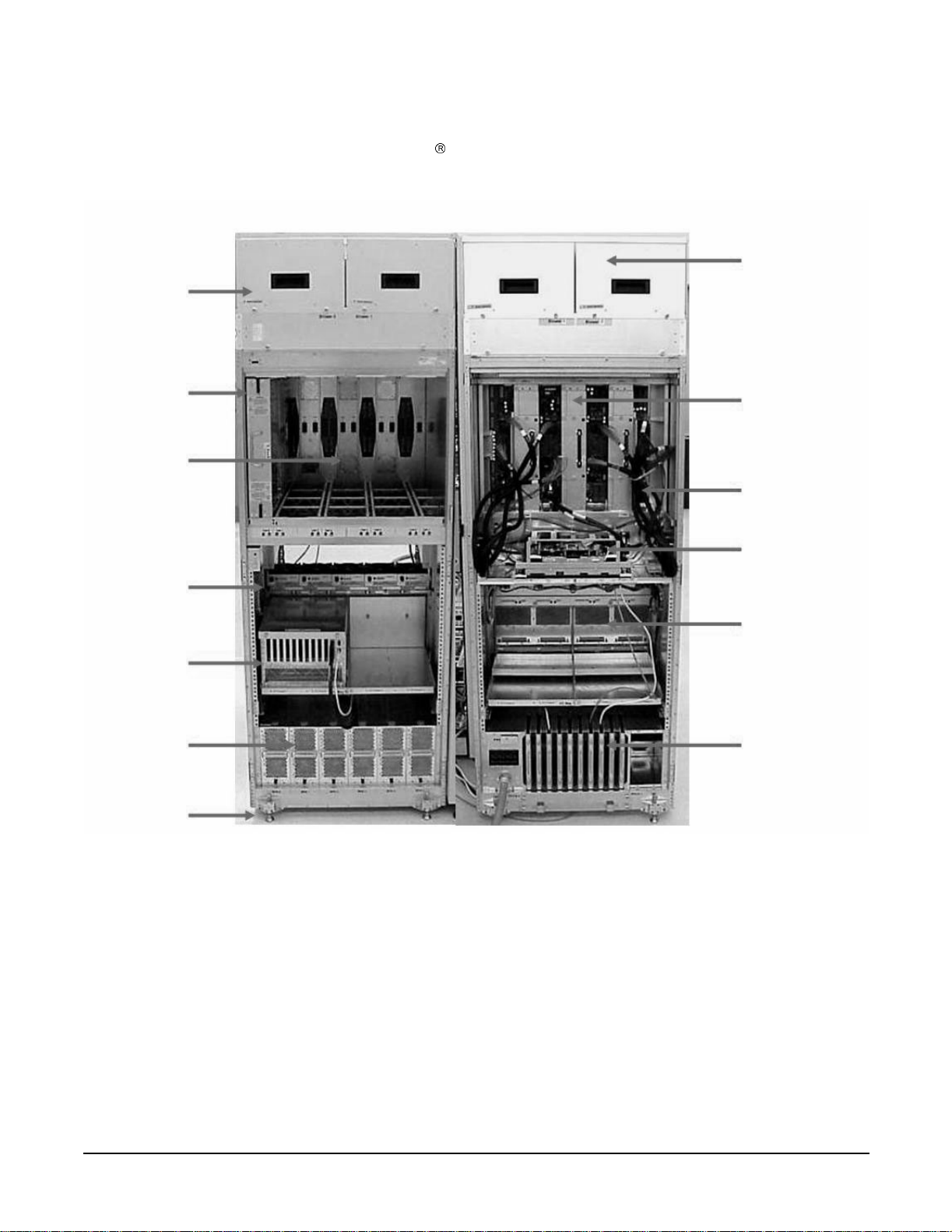
Figure 1-1 Superdome Cabinet
Blowers
Blowers
Cell
Backplane
I/O Fans
I/O Chassis
ower Supplies
Leveling Feet
Backplane
Power
Cables
Utilities
I/O Chassis
PDCA
Cable Groomer
Chapter 1
25
Page 26

Overview
Power System
Power System
The power subsystem consist s of the follo win g componen t s:
- 1 or 2 Power Distribution Component As sembly (PDCA)
- 1 Front End Power Supply (FEPS)
- Up to 6 Bulk Power Supplies (BPS)
- 1 power board per cell
- An HIOB power system
- Backplane power bricks
- Power monitor (PM) on the Universal Glob of Utilities (UGUY)
- And local power monitors (LPM) on the cell, the HIOB and the backplanes.
AC P ow er
The AC power system includes one or two PDCAs and one FEPS .
The FEPS is a modular, 2n+2 shelf assembly power sys t em t h at can consume up t o 17 KVA of pow er from A C
sources. The purpose of the FEPS chassis is to provide interconnect, signal and voltage busing between the
PDCAs and BPSs, between the BPSs and utility subsystem, and between the BPS and the system power
architectu re. The FEPS subsystem comprises of three dist inct modu lar assemblies: s ix BPS, two PDCAs, and
one FEPS chassis.
At least one 3 -phase PDCA per Superdome cabinet is required. For redundancy a second PDCA per cabinet
may be provided. The purpose of the PDCA is to receive a single 3-phase input and output three 1-phase
outputs with a voltage range of 200 to 240 volts regardless of the AC source type. The PDCA also provides a
convenience disconnect switch/circuit breaker for service, test points and voltage present LED indicators. The
PDCA is offered as a 4-wire or a 5-wire PDCAdevice . Separate PDCA ’s (PDCA-0 and PDCA-1) may be
connected to 4-wire and 5-wire input source simultaneously as long as the PDCA internal wiring matches the
wiring configuration of th e AC so urce
The 4-wire PDCA is used in a phase to phase voltag e rang e of 200 to 240 volts at 50/60 Hz. This PDCA is
rated for a maximum in put cu rrent of 44 Amps per phase. The AC input power line to the PDCA is con ne ct ed
with power plugs or is hardwired. When using power plugs, use a power cord [OLFLEX 190 (PN 6008044)
four conductor 6-AWG (16mm), 600 V, 60 Amp, 90°C, UL and CSA approved, conforms to CE directives
GN/YW ground wire].
Following recommend plugs for the 4-wire PDCA are:
- In-line connector: Mennekes ME 460C9, 3-phase, 4-wire, 60 Amp, 250 V, UL approved, color blue, IEC309-1
grounded at 9:00 o'clock.
- Panel-mount receptacle: Mennekes ME 460R9, 3-phase, 4-wire, 60 Amp, 250 V, UL approved, color blue,
IEC309-1 grounded at 9:00 o'clock.
The 5 wire PDCA is used in a phase-to-neutral voltage ran ge of 200 to 240 Vac 50/60Hz. This PDCA is rated
for a maximum inpu t cu rr ent of 24 Am p s per ph ase. Th e AC input power line to the PDCA is connected with
power p lugs or is ha rd wired. When usin g p ower plugs, a power cord [ f ive co nductors, 10-AWG (6 mm),
450/475 V, 32 Amps, <HAR< European wire cordage, GN/YW ground wire]. An alternative is for the customer
to provide t he power plug including the power cord an d the receptacle. Recommended plugs:
26
Chapter 1
Page 27

Overview
Power System
- Inline connector: Mennekes ME532C6-16, 3-phase, 5-wire, 32 Amps, 450/475 V, VDE certified, color
red,IEC309-1, IEC309-2, grounded at 6:00 o'clock.
- Panel-mount receptacle: Mennekes ME532R6-1276, 3-phase, 5-wire, 32 Amp, 450/475 V , VDE certified, color
red, IEC309-1, IEC309-2, grounded at 6:00 o'clock.
- FUSE per phase: 25 Amp (valid for Germany).
DC Power
Each power supply output provides 48 V dc up to 60 A (2.88kVA) and 5.3 V dc housekeeping. Normally an
SD32 Superdome cabinet contains six BPS independent from the installed amount of cells and I/O. An SD16
normally has four B PS instal led.
System Power On Sequence
The general power up sequence order is as follows:
1. AC power cord is pulled in and front end power supply (FEPS) breakers closed.
2. Housek eepin g ( HK P ) powe r is applie d. Util itie s init ialization and the comple x conf ig uration is checked.
3. Power switch on and the cabinet 48V power is enable d.
4. SPU cabinet main back plan e power ed on and rese t. The main system backplane comes up first and
supplies clocks to cells and I/O backplanes. Backplane XBCs must be read y by the time cell cont rolle rs
initialize.
5. I/O backplanes are powered on.
6. Cell boards are powered on.
7. SUB queries cells for valid complex profiles. Cells must be powered up with 48 V in addition to HKP. When
one valid cell is located, a timer star ts and cell bo ards not ready, after the time r counts down, will not be
initialized.
8. Early CPU _IN IT and cell m onarch selections begin.
9. Cell board nitialization begin.
10. Partitions seek rendezvous and perform core-cell selections.
11. Partition domains are Iinitialize d .
12. IPL is launched.
Enabling 48 Volts
The PM is responsible for enabli ng 48 V, but it must have permission from the MP. To enable 48 V, the
transition cabi ne t pow e r swit ch m us t be mo ve d from OFF to O N. Or you can use the MP com m and pe if the
power switch is already on. (If switch is on the cabinet wakes up from power on reset).
If the PM has permission, it sends a PS_CTL_L signal to the FEPS. Then the BPS enables 48 V converters
which send 48 V to the backplane, I/O Chassis, HUCB, cells, fans, and blowers. Once the 48 V is enabled, it is
cabled to the backplane, cells, and I/O chassis(s).
Chapter 1
27
Page 28

Overview
Cooling System
Cooling System
The Superdome has fou r blower s and five I/O fans per c abinet . These co mponents a re all h ot-sw ap devices . All
have LEDs indicating the current status. Thes e LEDs are self-enplanation. Temperature monitoring occurs
for the following:
- Inlet air for temperature increases above normal
- BPS for temperature increases abov e normal
- The I/O power board over temperature signal is monitored.
The inlet air sensor is on the main cabinet, located near the bottom of cell 1 front. The inlet air sensor and the
BPS sensors are monitor ed by the PM3 (on the UGUY), an d the I/O power board sensor s are monit ored by the
cabinet level utilities (CLU) (on the UG U Y) .
The PM controls and monitors the speed of groups of N+1 redundant fans. In a CPU cabinet, fan Group 0
consists of the four main blowers and fan Group 1 consists of the five I/O fans. In an I/O Expansion (IOX)
cabinet, fan Gro ups 0 thru 3 consist of four I/O fans and fan Group 4 consists of 2 manage m e nt subsyste m
fans. All fans are expected to be populated at all times (with the exception of the OLR of a failed fan).
The main blowers feature a variable spe ed contr ol . The blow ers operat e at full spe ed there is cir cu i t ry
available to REDUCE the normal operating speed. All of the I/O fans and managed fans run only at 1 speed.
The PM controls fans through the use of the following resources:
- fanReference D/A (for main fans only)
- tachSelect register
- 930 Port 3.5 (T1) and 930 Timer 1
- FAN_SPEED_HIGH and FAN_SPEED_NORMAL message (for main fans only)
- 16 blower/fan present signals
- 2 manageability fan present signals
- 16 blower/fan fail signals
- 2 management fan fail signals
When the PM queries the entities for their maximum power c onsumption, the cells also send a v alue
describing the desired NORMAL m ain f an sp ee d . Cells o f the sam e ar chit ectu re se nd id entical values. If the
PM receives differing values, it uses the largest value.
One minute after setting the main blower fanReference to the desired speed or powering on the cabinet, the
PM uses the tach select register to cycle through each fan and measure its speed. When a fan is selected,
Timer 1 i s used in counter mode to count the pulses on port T1 over a period of 1 second. If th e frequency does
not equal the expected frequency plus some ma rgin of error, the fan is considered to hav e failed and is
subtracted from the working fan count.
28
Chapter 1
Page 29

Overview
Cooling System
If the failure causes a transition to N- I/O or main fans in a CPU cabinet, the cabinet is immediately powered
off. If the failure causes a transition to N- I/O fans in an IOX cabinet, the I/O backplanes contained in the I/O
Chassis Enclosure (ICE) containing that fan group are immediat el y powered off.
Only inlet tempe rat ur e inc reases will be monitored by HP U X, all othe r hig h te mp e ratu re inc rea s e chassis
codes will not activa te the envd daemo n to act as con figured in the /etc/en vd .co nf. The PM mo nit ors am bie nt
(inlet) temperature. The PM polls an analog-to-digital converter to read t he current ambient temperature.
The temperature fall s into one of four ranges: Normal, OverTempLow , OverTempMid, or OverTempHigh. The
following state c odes machine describes the actions taken based on the various temperature state transi tion s:
OTL_THRESHOLD = 32C -----> send error code PDC_IPR_OLT
OTM_THRESHOLD = 38C ----> send error code PDC_INT_OTM
OTH_THRESHOLD = 40C -----> shut down 48 V
NOTE In an I/O expansion (IOX) cabinet, the thresholds are set 2 degrees higher to compensate for
the fact that the cab ine t se nsor is mounted in a ho t spo t.
Chapter 1
29
Page 30

Overview
Utilities Subsystem
Utilities Subsystem
The Superdome utilities subsystem is comprised of a number of hardware and firmware components located
througho ut th e Su p erd o m e syste m.
Platform Management
The sx2000 platform management subsystem consists of a number of hardware and firmware components
located throughout the sx2000 sy ste m. The sx2 000 use s th e sx1000 p latform m anagement components, with
firmware changes to su ppor t ne w functionality.
The following list descr ibes the major hardwa re components of the platform management subsystem and the
changes required for the sx20 00:
The PDH microcontroller i s locat ed on Cell 's PDH Daughter-card assembly. It provides communication
betw e en th e M anag e men t fi rmwa re, the P DH spa ce, an d t he USB bus. The m i croco n t roll e r repr esents a
change from the prior implementation, Intel
(ARM). This microc o ntr olle r change enable s th e PDH da ughter-card design to be compat ible a cros s all thr ee
new CEC platforms. It also enables the extra processing power to be used to move the console UARTs into
PDH memory space located on the Cell elimin atin g the sx1 000 Co re I/O (CIO) card.
80C251 processes, to a more powerful 16-bit microcontroller
The Universal Glob of Util iti es (UGUY) on Super dome contains the power monitor (PM), the cabinet le vel
utilities (CLU), and the syst e m clock sour ce cir cu itry. No change s are pl ann ed f or the sx2000 but the entire
clock section on the UGUY assembly is made obsolete by new redundant clock source circuitry.
The CLU circuitry on the UGUY assembly that provides cabinet -evel cable interconnect for backplane and
I/O card cage utility signal communication and scan support.
The PM circuitry on the UGUY assembly monitors and controls the 48 V dc, the cabinet environment
(ambient temperature and fans), and controls power to the entities (cells, I/O bays).
The Management Pr ocessor (MP) is a single board computer (SBC) that controls the console (local and
remote), the fron t pan e l disp lay and its red ir ec tion o n the con so le, main tains logs for the Event ID s,
coordinates messages between dev ices, and performs other service processor functions.
The SBCH board provides USB hubs into the cabinet from an upstream HUB or the MP. No changes are
planned for the sx2000.
IPF Firmware
- The firmware supports four different operating systems (HP-UX, Linux, Windows, OpenVMS)
- The firmware is complia nt wit h I PF ind u str y standards (SAL, PAL, ACPI, EFI)
- Provides an IPMI (intelligent platform management interface)
- Supports architecture that extend s acros s p rod uc t line and ne xt ge n er atio n syste m s
- Supports a new interface for user (mfg./diag/), etc.
- Supports PCI hot-plug
- Supports cell hot-plug (online add and delet e)
- Supports I/O chassis hot-plug (online add and delete)
- Suppo rt s C e l l- L ocal mem ory
30
Chapter 1
Page 31

Overview
Utilities Subsystem
- Suppo rts U S B f o r ke yboard a nd mouse at b o ot
- Supports VGA during boot
- Enables global shared memory (GSM)
- Supports PCI 2.3, PCI-X 1.0, and PCI-X 2.0
UGUY
Every cabinet co ntains one UGUY. Refer to Figure 1-2. The U G UY plugs into the HUCB. It is not hot
swappable. Its MP microproc essor controls power monitor functions, executing the Power Monitor 3 (PM3)
firmware and the cabinet-level utility (CLU) firmware.
The UGUY consists of two main components:
- CLU
- PM3
Figure 1-2 UGUY
CLU Functionality
The CLU is respons ible for colle cti ng and repo r ting the configurat io n info rmation for itself, main backplan e,
I/O backplanes , and the SUB/HUB. Each of these boards is furnished with a configuration EEPROM
containing FRU IDs, revision information, and, for the main backplane and I/O backplanes, maximum power
requirement s for that e ntit y in its fully co nfigured, fully loaded st ate. The pow e r requ irem ent information is
sent to the PM3 autom atically when HKP is ap plie d or whe n a new e ntity is plugged in. The configu rat io n
information is se nt to the SU B in resp onse to a get_config command.
The CLU gathers the following information over its five I2C buses:
- Board revision information is contained in the board's configuration EEPROM for the UGUY board (UGUY),
the SBCH board (SBCH), the main backplane, the main backplane power boards (HB PB), the I/O backplane
(HIOB), and the I/O backplane power boards (IOPB).
- Power requiremen t s from the configur ation EEPROM for the main backplane (HLSB or HRSB), the I/O
backplanes (HIOB). This information is sent to the PM3 processor (via USB) so that it can calculate cabinet
power re q uireme nts.
- Power control and status interface. Another function of the UGUY is to use the power_ good s i gna l s to drive
power on
- Reset control wh i ch includes a re set for ea ch I /O b a ck p l ane, a main backp l ane ca binet res e t, TR ST - JTAG
reset fo r a ll JTA G scan chai ns in entire cabinet, a sy s te m clock con trol mar gin contr o l
Chapter 1
31
Page 32

Overview
Utilities Subsystem
- Status LEDs for the SBA cable OL*, the cell OL*, and the I/O backplane OL*
PM3 Functional ity
The PM3 performs the following function s :
1) FEPS control and monitoring. For each of the BPSs in the FEPS.
Superdome has six B PS and the UG U Y se nds 5 V to the BP S for use b y the fa ult collection circuitr y.
2) FAN control and m o nito r ing.
In addition to the blowers , there are five I/O system fans (above and between I/O bays). Th ese fans run at full
speed all the time (there is no fan speed s ignal).
3) Cabinet mode and cabinet number fan out.
There is a surface mount DIP switch on the HUCB (UGUY backplane) can be used to configure a Superdome
cabinet for normal use or as an SD16 cabinet. Use the 16-position thumb switch on the UGUY to set the
cabinet number. Numbers 0-7 are for CPU oriented cabinets and numbers 8-15 are for I/O-only cabinets.
4) Local Power Monitor (LPM) interfaces.
Each big board (cell board, I/ O backplane, and main backplane) contains logic that controls conversion of 48
V to lower voltages. The PM3 interfaces to the LPM with the board-present input signal to the PM3 and the
power-enable output signal from the PM3.
5) Front and rear panel board controls.
System Clocks
The sx2000 clocks are supplied from the backplane and to the backplane crossbar ASICs and the cell boards.
There is no distribution of the system clocks to the I/O backplanes. Instead, independent local clock
distribution is provided on the I/O backplane.
Managemant Processor (SBCH and SBC)
The management processor (MP) is comprised of two PCBs, the SBC (single-board computer) and the single
board computer hub (SBCH), forms one functional unit. The MP is a hot-swappable unit powe red by +5 V
HKP that holds the MP configuration param ete rs in compac t flash and the error and activity logs and the
complex identification informat io n (complex prof ile) in battery backed NVRAM. It also provides the USB
network controller (MP bus). Each complex has one MP per complex. It cannot be setup for redundancy.
However, it is not a single point of failure for the complex because it can be hot-swapped. If the MP fails, the
complex can still bo ot and function. Howev e r, the following utility function ality is lost until the MP can be
replaced:
32
Chapter 1
Page 33

-The ability to process and store log entries (chassis codes)
- Console functions to every partition
- OL* functions
- Virtual front panel and system alert notification
- The ability to connect to the MP for maintenance, either locally or remotely
- The ability to run diagnostics (ODE and scan)
Figure 1-3 Management Processor
SBC
Overview
Utilities Subsystem
SBCH
UGUY
The SBCH provides the physical and electrical interface to the SBC, the fanning out of the universal serial
bus (USB) to internal and external su bsys tem s, and a LAN 10/100BT eth ernet con ne ctio n. It plugs into the
HUCB and is hot swappable. Every CPU cabinet contains one SBCH board, but only one SBCH contai ns an
SBC board used as the MP for the complex. The remaining SBCH boar ds act as USB hub s.
The SBC board is an embedded pc running system utility board (SUB) firmware. It is the core of the MP. It
plugs into the SBCH board through a PC104 interface. The SBC provides three external interfaces to the
utility subsys te m :
- LAN (10/100BT ethernet) for customer console access
- RS232 port, for remote access from the response center th roug h a modem
- RS232 port, for local console access for manufacturing and field support personnel
The modem func tio n is not included on the SBC and must be exte rn al to the cabin et.
Compact Flash
The compact flash is a PCMCIA-style mem ory card that plug s into the SBC bo ard. It stores the MP MP
firmware and the customer's MP configuration parameters. The parameters stored in the compact flash are:
- The network configuratio ns for both the publ ic and priv ate LANs
- User name and passwo r d com binations for logging in to the M P
- Baud ra t e s f or the seri al port s
- Paging parameters for a specified alert level
Chapter 1
33
Page 34

Overview
Utilities Subsystem
HUCB
The HUCB, shown in Figure 1-4, is the backplane of the utility subsystem. It provides cable distribution for
all the utility signals except the clocks. It also provides the customer LAN interface and serial ports. The SMS
connects to the HUCB. The system type switch is located on the HUCB. This board has no active circuits. It is
not hot-swappab le.
Figure 1-4 HUCB
34
Chapter 1
Page 35

Overview
Backplane (Fabric)
Backplane (Fabric)
The system backplane assembly provides the following functionality in an sx2000 system:
- Interfaces the CLU subsystem to the sys te m back pl ane and cell m o d ules
- Houses the system cro ssbar switc h f abrics and cell m o dule s
- Provides switch fabric interconnect between multiple cabinets
- Generates system clock so urces
- Pe rf orms redundant system clock source sw itching
- Distributes the system clock to crossbar chips and cell modules
- Distributes housekeepi ng power to cell modules
- Terminates I/O cables to cell modules
The backplane supports up to eight cells, interconnected via the crossbar links. A sustained total bandwidth
of 25.5 GBs is provided to each cell. Each cell connects to three individual XBC ASICs. Th is connection
enables a single chip crossing when a cell communicates with another cell in its four-cell group. When
transfering data between cells in diffe ren t groups, two crossbar links are provided to compensate for the
resultant multiple chi p cro ssi ngs. This to p olo gy also provides for switch fabric r edu nd an cy
Dual rack/backplane systems contain two identical backplanes. These backplanes use 12 high-speed interface
cables as interconnects instead of the flex cable interface previously employed for the legacy Superdome
crossbar. T he sus taina ble bisection ba ndwi dt h betwe en ca binets is 72 GBs at a link speed of 2.1 GT/s.
Crossbar Chip - XBC
The crossbar fabrics in the sx2000 are implemented using the XBC crossbar chip. Each XBC is a
non-bit-sliced , eig ht-port no n-blocki ng cro ssbar th at can commu nicate wit h the CC or XBC ASICs . Eac h of the
eight ports is full duplex, capable of transmitting and receiving independent pack ets simultaneously. Each
port con s is ts of 20 chan ne l s o f IBM s HSS technology. Eighteen chan ne l s a r e used for p acket data . One for
horizontal link parity, and one channel as a spare. The HSS channels can run from 2.0- 3.2 GT/s. At 3.0 GT/s,
each port prov ides 8.5 GBs of sustainable bi-directional data bandwidth.
Like the CC and the SBA, XBC implements link-level retry to recover from intermittent link errors. XBC can
also replace a hard-failed channel with the spare channel during the retry process, which guarantees
continued reliabl e operation in the event of a broken channel plus single or multi b it i ntermittent errors.
XBC supports enhanced secur ity betwee n hard partiti ons by provid ing write prot ection on key CSRs. With out
protection, CSRs such as the routing table s could be modified b y a "rogue" OS, causing other hard partitions
in the system t o crash. To prevent this, key CSRs in XBC ca n only be modified by packets hav i ng the "Secure"
bit set. This bit is set by the CC based on a register that is set only by a hard cell reset, which causes secure
firmware to be entered. This bit is cleared by secure firmware before passing control to an OS.
Switch Fabrics
The system backp lane houses the switch fab ric that connects to each of the cell modules . Th e cr ossb a r swit ch
is implemented by a three-link-per-cell topology: three independent switch fabrics connected in parallel. This
topology provides switch fabric redundancy in the crossbar switch. The backplane crossbar can be extended to
Chapter 1
35
Page 36

Overview
Backplane (Fabric)
an additional crossbar in a second backplane for a dual backplane configuration. The connection is through a
high-speed cable interf ace to the seco nd backp lane. This 12-c able high -sp eed int erfac e replac es the fl ex cable
interface previously used on the Superdome system.
Backplane Monitor and Control
The backplane implements the following monitor and control functions.
- Backplane detect and enable function s to and from the CLU
- Backp lane LED cont rols from the CLU
- Bac kplane JTAG dist r ibutio n and chain s
- Cabinet ID from the CLU
- Reset and power manager FPGA (RPM) and JTAG interface and header for external programming
- XBC res e t, configur a tion and contro l
- IIC bus distribution to and from the CLU
- Clock sub system monitor and co ntrol
- Power supply monito r an d co ntrol
- Cell detect, power m onito r, reset and rnable to and from the CLU
- JTAG and USB data distribution to and from ea ch cell codule
- Cell ID to each cell module
- OSP FPGA functional i ty
I2C Bus Distribution
The sx2000 system I2C bus extends to the Superdome backplane (SDBP) assembly through a cable connected
from the CLU subsystem. This cable conne cts from J17 on the CL U to J64 on the SDBP. T he clock and dat a
signals on this cable are bu ffered through I2C bus extenders on the CLU and on the backplane.
The I2C bus is routed to an I2C multiplexer on the backplane where the bus is isolated into fou r bus
segments. Th ree bus segments are dedicated to connection s to the three RPMs. The remaining segmen t is
used to daisy-chain the remaining addressa ble devices on the bus. Each bus segment is addressed through a
port on the I2C multip lexer.
Clock Su bsystem
The backplane houses two hot-swap oscillato r (HSO ) mo dule s. Each HSO bo ar d gen er ates a system clock
which feeds into the backp lan e. Each HSO ou tput is routed to the redundan t clock sour ce (RC S) mod ule. The
RCS module accepts input from the two HSO modules and produces a single system clock, which is
distributed on the back plane to all cell modules and XBC ASI Cs.
36
Chapter 1
Page 37

Overview
Backplane (Fabric)
System Clock Distribution
The following system components receive the system clock are the eight cell boards that plug into to the
backplane, the six X BC crossbar switch ch ips on the system backplane. Two backplane clock power detectors
– one for each 8- w a y sine clock po wer splitter are on the RCS. Th e b a ck pl ane power detector sits at the end of
the clock tree and measures the amplitude of the clock from the RCS t o det ermine if it is providing a signa l of
the correct amplitude to the cell boards and XBCs. Its output is also an alarm signal to the RPM FPGA.
System clocks can o riginat e from fou r inpu t sources : the s ingle-en ded exter nal cl ock i nput MCX conn ector, the
280 MHz margin oscillator on the redundant clock sour ce (RCS) board, or from one of the 266.667 MH z
oscillator s on one of th e HSO modules . The source s election is det ermined eit her by fi rmware or by logi c in the
RCS.
The clock source has alarm signals to indicate the following health status conditions to the cabinet
management subsystem:
- Loss of power and loss of clock for each of the clock oscillator boards
- Loss of clock output t o the backplanes
The sx2000 clock system differs from the sx1000 clock system in that the system clocks are only supplied to
the backplane crossbar ASICs an d the cell boards. System clocks are not d istr ibut ed to the I/O backplan e s.
Instead, independent local clock distribution is provided on the I/O backplane.
Hot-Swap Oscillator
Two hot-swappable clock oscillators combine the outputs of both oscillators to form an N+1 redundant fault
tolerant cloc k source. The result a nt clock source will drive clocks over connecto r and cable int erfaces to the
system backplanes.
The hot-swap oscillator board contains a 266.667 MHz PECL oscillator. The output from this oscillator drives
a 266.667 MHz band-pass SAW filter that drives a monolith ic IC power a mp lifier. The output of the power
amplifier is a 266.667 sine wave clock that goes to the RCS. The module also has two LED s that are visible
through the module handle. One LED is green and the other is yellow. Table 1-1 describes the HSO LEDs.
The electrical signal tha t controls the LEDs is driven by the RCS.
Tabl e 1-1 HSO LED Status Ind icat o r M eani ng
Green LED Yellow LED Meaning
on off Module OK – HSO is produci ng a clock of the correct amplitude and
frequenc y a nd is p lugged into its connector.
off on Module needs attention – HSO is not producing a cl ock of the
correct amplitude or frequency and is plugged into its connector.
off off Module power is off.
Chapter 1
37
Page 38

Overview
Backplane (Fabric)
The HSO connects to the system backplane through an HMZD2X10 right-angle receptacle.
sx2000 RCS Module
The sx2000 RCS module sup plies clocks to the Su perd om e sx2000 back plane, communicates clock alarm to
the RPM, and accepts control input from the RPM. It has an I2C EEPROM on the module so that the the
firmware can inventory the module on system power up.
The RCS supplies 16 copies o f the sine wave system clock to the sx2000 sy ste m back plane . Eight cop ies go to
the eight cell boards, six copies to the six XBCs on the system backplane, and two copies to the backplane
clock power detector.
In normal operati on the RCS s el ec t s one of the two HSOs as t h e s our ce of clocks for the platform. Which H SO
is selected depends whether the HSO is plugged into the backplane and on whether it has a valid output level.
This select ion is overridden if there is a con nection from the clock input MCX con nector on the master
backplane. Figure 1-5 shows the lo cati ons of th e HSOs and RCS on the backplane.
Figure 1-5 Locations of HSO and RCS
HSO 0
HSO 1
RCS
If only one HSO is plugged in and its output is of valid amplitude then it is selected. If its output is valid, then
a green LED on the HSO is lit. If its output is not valid, then a yellow LED on the HSO is lit and an alarm
signal is sent from the RCS to the RPM. The RCS pro vide s a clock that is app roximately 100 KHZ less than
the correct frequency even if the outpu t of the HSOs are not of valid amplitude or no HSOs plugged in.
If both HSOs are plugged in and their output amplitudes are valid, then one of the two is select ed as the clock
source by logic on the RCS. The green LEDs on both HSOs will be lit.
38
Chapter 1
Page 39

Overview
Backplane (Fabric)
If one of the HSOs outputs does not have the cor re ct ampl i t ude then the RCS uses the other one a s t h e s ource
of clocks and sends an alarm signal to the RPM indicating which oscillator failed. The green LED is lit on the
good HSO and the yellow LED is lit on the failed HSO.
If an external clock coax is connected from the master backplane clock output MCX connector to the slave
backplane clock input MCX connector then, this overrides any firmware clock selections. The clock source
from the slave backplane will be the m aste r backplane.
If firmware selects the margin oscillator as the source of clocks, then it is the source of clocks as long as there
is no connection to the clock input MCX connector from the master backplane.
If the firmware selects the external margin clock SMB connectors as the source of clocks, then it is the source
of clocks as long as no connection exists t o the clock input M CX connector from the master backplane.
Cabinet ID
The backplane receives a 6-bit cabinet ID from the CLU interface connector J64. The cabinet ID is buffered
and routed to eac h RPM a nd to each Cell module slot. The RPM decodes t he cab i net n umber from the cabinet
ID and uses this bit to alter the cabinet number bit in the ALBID byte sent to each XBC through the serial bit
stream.
Cell ID
The backplane generates a 3-bit slot ID for each cell slot in the backpl a n e. The slot ID and 5 bits from the
cabinet ID are passed on to each cell module as the cell ID.
Backplane Power Requirements and Power Distribution
The dc supply for the backplane ass e mbly is from the cabin e t pow er supp ly subsy ste m thro ugh two powe r
cables attached to th e backplan e. Connect ors for t he dc supply input hav e the same referen ce designat ors and
are physically located in the same position as on the Superdome system backplane. The power cables are
reused cable assemb lies from the Super dome system a nd the supply connecti on is not redundant. O ne cabl e is
used for 5V housekeeping supply input and th e second cable is used for 48 V supply input.
Chapter 1
39
Page 40

Overview
Backplane (Fabric)
The backplane has two slots for power supply modules. The power supply connector for each slot has a 1-bit
slot address to i dentify the slot. The address bit for power supply slot 0 is grounded. Th e address bit for slot 1
is floating on the backpl ane. The power supply module provides a pull-up resistor on the address line on slot
1. The power supply module uses the slot a ddress bit as bit A0 for generating a unique I2C address for the
FRU ID prom. Figures 1-7 and 1-8 identify and sh ow the lo cation of the backp lane p owe r su ppl y modu les.
Figure 1-6 Backplane Power Supply Module
Each power supply slot has a power supply modle detect bit used to det ermine if the power supply module is
inserted into the back p lane slo t. Th is bit is rout ed to an inp u t on the RPM' s. The RP M p rovide s a p ull-u p
resistor for logic 1 when the power supply module is missing. When the power supply module is inserted into
the slot, the bit is grou nded by the power supply and logic 0 is detec ted by the RPM, indic ating that t he power
supply modu le is pres en t in the back p lan e slot.
Figure 1-7 Backplane (Rear View)
Power Supply 0
XBC
Power Supply 1
40
Chapter 1
Page 41

Overview
CPUs and Memories
CPUs and Memories
The cell provides the proc es sin g and m emo r y resources required by each sx2000 system configuratio n. Each
cell is comprises the fol low ing components : fou r proc e sso r mo d ule so ck e ts, a single cell (or co herency)
controller ASIC, a high-speed crossbar interface, a high-speed I/O interface, eight memory controller ASICs,
capacit y for up to 32 double-data rate ( DD R ) DI MMs, high- s p e ed cl o ck distribut ion circuitry, a manageme nt
subsys te m in te rf ace, scan (JTA G) circuitr y f or ma nufactu ring test, a nd a low-voltag e DC p o w e r interface.
Figure 1-8 shows the locations of the major components.
Figure 1-8 Cell Board
CPUs
CC
Memory
Power
Cell Controller
The heart of t he cell design is the c ell controller (CC). Th e CC provides two front side bus (FSB) interfaces,
with each FS B connected to two processor modules. The communication bandwidth, 6.8 GBs sustained at
266.67 MH, on each FSB. this bandwidth is shared by the two processor modules on the FSB. Interfaces
external to the cell provi ded by the CC consist of three cross bar links , referr ed to as the fabric interface , and a
remote I/O subsystem link. The fabric interface enables multiple cells to communicate with each other across
a self-correcting, high-speed communication pathway. Sustained crossbar bandwidth is 8.5 GBs per link at 3.0
GT/s, or 25.5 GBs across the three link s.
Chapter 1
41
Page 42

Overview
CPUs and Memories
The remote I/O link provides a self-correcting, hig h-speed communication pathway between the cell and the
I/O subsystem through a pair of cables. Sustain ed I/O bandwidth is 5.5 GBs for a 50 percent inbound and
outbound mix, and roughly 4.2 GBs for a range of mixes . The CC interfaces to the cell's memory system. The
memory interface is capa ble of providin g a sust ained bandwidth of 14 to 16 GBs at 266.67 MH to the cell
controller .
Processor Interface
The CC has two separate FSB interfaces, and each of those FSB is connected to two processor sockets in a
standard three-drop FSB configuration. The CC FSB interface is pinned out exactly like that of its
predecessor CC, in order to preserve past cell routi n g. The CC pin out was specificall y designed to minimize
total routing delay wit ho ut sac ri fi cin g timing skew between the FSB address and data and control signals.
Such tight routing controls allow the FS B to achieve a frequenc y of 266.67 MH , and the data to be
transmitted on both edges of the interface clock. With the 128-bit Front Side Bus capable of achieving 533.33
MT/s, the desired 8.5 GBs bur st d ata tra nsfe r r ate can be realiz ed .
Processors
There are sever al processor families s upported and the processors are already installed on the cell board. All
processors require that a minimum firmware version be installed. See Table 1-2 for the processors supported.
Table 1-2 Supported Processors and Minimum Firmware Version Required
Processor Family
Itanium
Itanium
Itanium
Rules for Proces sor Mixing
• Processor families can not be mixed on a cell board or within a partition
• Processor frequenc ie s can no t be mix ed on a cell bo ard or within a partition
• Cache sizes can not be mixed on a cell board or within a pa rt ition
• Major processor steppin gs can not be mi xed on a cell board or within a partition
2 single-core processors with 9 MB cache 4.3e (IPF SFW 004.080.000) 1.6 GHz
2 dual-core processors with 18 MB cache 5.5d (IPF SFW 005.024.00 0) 1.6 GHz
2 dual-core processors with 24 MB cache 5.5d (IPF SFW 005.024.00 0) 1.6 GHz
Minimum Firmware
Version or Later
Core
Frequency
Cell Memory System
Each cell in the sx2000 system has its own independent memory system. This memory subsystem consists of
four logical memory subsystems that achieve a combined bandwidth of 17 GBs peak, 14-1 6 GBs sus tain ed.
This cell design is the first of the Superdome des igns to support the use of DDR I/O DRAM. These DIMMs are
to be based on DDR-II protocol, and the cell design supp o rts DI MM ca paciti es of 1, 2, 4 or 8 GBytes using
monolithic DRAMs. Non-mon oli thic, or stacked, DRAMS are not supported on the sx20 00, as the additional
capacitive load, and/or requirement for additional chip selects is not accommodated by the new chipset. All
DIMMs used in the sx2000 are compatible with those used in other new CEC platforms, although other
42
Chapter 1
Page 43

Overview
CPUs and Memories
platforms may support DIMMs based on non monolithic (or stacked) DRAMs, which are incompatible with
the sx2000. There is no support for the use of the older SDRAM DIMMs designed for Superdome. Cell
memory is illustr ate d in Figu re 1-9.
Figure 1-9 Cell Memory
DIMMs are named acc ord ing to both ph ysic al location and loading orde r. The physical location is used for
connectivity on the board , and is the same for all quad s. Physical locat io n is a letter (A or B) followed by a
number (0, 1, 2, or 3). The letter indicates which si de of the quad the DIMM is on, A being the left s ide , or the
side nearest CC. The DIMMs are then numbered 0 through 3, starting at the outer DIMM and moving
inwards the memory controllers.
Memory Controller
The memory controller CEC's primary function is to source addr ess and control signals and multiplex
de-multiplex data between the CC and the devices on the DDR DIMMs. Four independent memory block s,
consisting of two memory controllers and eight DIMMs, are supported by i nterface buses running between
the CC and the memory controller. The memory controller converts these link streams to the correct
signaling voltage levels (1.8 V) and timing for DDR2 protocol.
Bandwidth is limited by the memory inte rfac e buse s that tran sf er da ta be twee n the C C and the mem o ry
controller. The memory controller also perf o rms th e wr ite (t ag up date ) por tion o f a rea d-mo d ify- w rite (R MW )
access. The memory controller is bit sliced, and two are required to form one 72-bit CC memory interface data
(MID) bus. The CC MID buses are bidirectional, source synchronou s, and run at 533.33 MT/s. The memory
side of a pair of memory controller ASICs consists of two 144-bit bidirectional DDR2 SD RAM data bus es
operating at 533.33 MT/s. Each bus supports up to four echelons of DRAMs. An echelon consists of two
physical DIMMs (each 72-bits wide).
DIMM Architecture
The fundamental building block of the DIMM is a DDR2 DRAM with a 4-bit data width. Each DIMM
transfers 72 bits of data on a read/write, and the data is double-clocked at a clock frequency of 266.67 MHz for
an effective peak transfer rate of 533.33 MT/s. Each DIMM comprises 36 DRAM devices for data storage and
two identical cust om address buffer s . Thes e buffers fanou t and check t he parit y of address and control si gnals
received from the memory contr oller. The new sx2000 chipset DIMMs have the same mechanic al form factor
as the DIMMs used in Integrity systems, but the DIMM and the con nector, will be keyed differently from
previous DIMM desig ns to prevent improper installation. The DIMM is roughly twice the height of an
Chapter 1
43
Page 44

Overview
CPUs and Memories
industry-standard DIMM. This increase in height allows the DIMM to accommodate twice as many DRAMs
as an industry-standard DIMM and to provide redundant address and control signal contacts not available on
industry-sta nd ar d DDR 2 DI MM s.
Memory Interconnect
MID bus data is transmitted via the four 72-bit, ECC-protected MID buses, eac h with a c l oc k freque ncy equal
to the CC s core frequency. The data is transmitted on both edges of the clock, so the data transfer rate (533
MT/s) of each MID is twice the MID clock frequency (267 MHz). A configuration of at least eight DIMMs (two
in each quadrant) activates all four MID buses, and the theo retical bandwidth of the memor y subs yst em can
be calculated as follows: (533 MT/s * 8 Bytes/T * 4) = 17 GBs The MID buses are bit-sliced across two memory
control le rs with 36-bits of da ta go ing to each memory co ntroller. Each memo ry co ntrolle r, in turn, tak e s tha t
high-speed data (533 MT/s) from the MID, and combines four consecu tive MID tr ansfer s to form one 144-bit
DRAM bus. This DRAM bus is routed out in two 72-bit buses to two DIMM sets, which comprise four DIMMs
each. The DDR DRAM bus runs at 267 MT/s, and data is clocked on both edges of the clock.
The DDR DRAM address and control (MIA) signals for each quadrant origin ate at the CC and are routed to
the DIMMs thr o ugh t he mem o r y co nt ro lle r. On previous system s, these signals did not touch the m e m o ry
chips. Instead they were routed to the DIMMs through fan-out buffers. Th e DRAM address and control
signals are protecte d by pa rity so that sign aling errors are detecte d , and do no t caus e silent d ata corr up ti on .
The MIA bus, comprised of the SDRAM address and control signals, is checked for parity by the memory
controller. Each of the thirty-two DIMMs can genera ting a unique parity error signal that is routed t o one of
four parity error inputs per memory controller. Each memory controller then logically gates the DIMM parity
error signals it receiv e s with its own internal parity checks for the MIC and MI T buse s. This logical gating
results in a single parity erro r outpu t that is drive n to the C C and latch ed as an eve nt in an inte r nal
memory-mapped register.
Eight unique buses of comm and and co n trol sig nals are tran sm itte d from the CC to each mem ory contr oller
simultaneou sly wit h the ap prop ri ate MI D bus in te rc onne c t. Each mem o r y inter fa ce co ntr o l (MI C) bus
comprises four signals running at 533 MT/s. Each command on the MIC bus takes four cycles to transmit, and
is protected by parity so that signaling errors are detected and not cause silent data corruption.
Four memory interface tag (MIT) buses are routed between the CC and the designated tag memory
controllers. MIT buses run at 533 MT/s and use the same link type as the MID bus e s. Each MIT bus
comprises six signals and a differential strobe pair for de-skewing. As with the MIA and MIC buses, the MIT
is protected by par ity so that si gna ling errors will be dete cted and thus not cause silent data corruptio n.
Mixing DIMMs of Different sizes
Mixing of different sized DIMMs is allowed, provided the following rules are obeyed:
- An echelon of DIMMs consists of two DIMMs of the same type.
- All supported DIMM sizes may be present on a single cell board at the same time, provided previ ous rule is
satisfied.
- Memory must be added in increments of one echelon.
- The amount of memory contained in an interleaved grou p must be 2n bytes.
Memory Interleaving
Memory is interleaved in the fol lowing ways on the new sx2000 systems:
- MBAT (across DIMMs)
44
Chapter 1
Page 45

Overview
CPUs and Memories
- Cellmap (across cells)
- Link (across fabrics)
Memory Bank Attribute Table
The MBAT interleaving is done on a per-cell basis before the partition is rendezvoused. The cell map and
fabric interleaving are done af ter th e partition has rende zvo u se d . SDR A M on the cell boa rd is inst alle d in
physical units called eche lons. For the new sx2000, there will be 16 indepe nde nt echelons. Each echlon
consists of two DDR DIMMs. Each rank can have multiple internal logical units called banks, and each bank
contains multiple rows and columns of memory. An interleaving algorithm is used to determine how a rank,
bank, row, or column address is formed for a partic ular physic al add ress.
The 16 echelons in the memory subsystem can be subdivided as follows: Four independent memory quadrants
are accessed by four independen t M ID buses. Each quadran t cont ains two ind epen d ent SDRAM buses. Four
echelons can be installed on each SDRAM bus. The CC contains four MBATs, one for each memory quadrant.
Each MBAT conta ins 8 sets of routing CSRs, or one per rank. Each routing CSR specifies the bits of the
address that are masked or compared to select the corresponding rank, ref e rr ed to as inter l ea v e bit s. The
routing CSR also specifies how the remaining address bits are routed to bank, row, and column address bits.
T o optimi ze b andw i dth, co nsecu t i ve memory accesses are used to target echelons that are as far from each
other as possible . For this reason , t he interleaving algorithm programs the MBATs so that cons ecutive
addresses target echelon s in an order th at sk ip s first across quadrants, then across SDRAM bus es, then
across echelon s per SD RA M bus, then across banks per ran k.
Cell Map
Cell mapping cr eates a scheme that is easy to implement in hardware and to enable calculation of the
interleavin g parameters for softwa re. In order to do this , part of the physic al address per forms a lookup into a
table which gives the actual physical cell and the ways of interleaving into memory at this address. In order to
accomplish this th ere are some const raints:
- A portion of memory that is being interleaved across must start at an offset that is a multiple of the memory
chunk for that entry. For example, t o inte rlea ve across 16 GB of memory with one entry, the starting address
for this chunk must be 0 GB, 16 GB, 32 GB, 48 GB, and 64 GB. If using three 2 GB entries to interleave across
three cells, then the multi pl e mus t be 2 GB, not 6 GB.
- Interleaving is performed acr oss the actu al cells within the system. Inte rl eaving may be done acro ss a
minimum of 0.5 GB on a cell, and a maximu m interleave acr oss 256 GB p er cell.
- Each cell in an interleave group must have the same amount of memory interleaved. That is, you cannot
interleave 2 GB in one cell and 4 GB in an ot he r cell .
Link Interleaving
The link interleavi ng f un cti on ality did no t exist in the sx1000. This logic is new f or the sx2000 CC. The
sx2000 allows cells to be conne cted thr o ugh multip le p aths. In particu lar, each CC chip has three crossbar
links. When one CC sen d s a packe t to ano the r CC, it must specif y wh ich lin k to use.
The cell controller chip (CC) of the sx2000 chipset interfaces to processors, main memory, the crossbar fabric,
an I/O subsystem and processor dependent hardware (PDH). Two data path cpu bus interfaces are
implemented, wit h suppor t for u p to four p roc es so rs on each bus. The address bus is 50 bits wide, b ut only 4 4
bits are used by the CC. Error correction is provided on the data bus and parity protec tion is provided on the
address bus.
Chapter 1
45
Page 46

Overview
CPUs and Memories
Memory Error Protection
All of the CC cache lin es are prot ected in memory by an erro r correction co de (ECC). The sx2000 memory ECC
scheme is significantly different from the sx100 0 mem o r y EC C sche me. An ECC code wo rd is contained in
each pair of 144-bit chunks. The memory data path (MDP) block is responsibl e for checking for and, if
necessary, correcting any correctable errors.
DRAM Erasure
A common cause of a corr ectable memory error is a DRAM failure, and the ability to correct this ty pe o f
memory failure in hardware is sometimes known as chip kill. Address or control bit failure is a common
cause. Chip kill ECC schemes have added hardware logic that allows them to detect and correct more than a
single data bit error when the hardware is programmed to do so. A common implementation of traditional
chip kill is to scatter data bits from each DRAM compon ent acr o ss mult ip le ECC codewords, such that only
one bit from each DRAM is used per ECC codeword.
Double chip kill is an extension to memory chip kill that enables the system to correct multiple ECC errors in
an ECC code word. HP labs developed the ECC algorithm and th e first implemen tation of t his tech nology is in
platforms using the sx200 0 chipse t. Do uble chi p kill is also kn own as DR AM erasure.
DRAM erasure is invoked when the number of correctable memor y errors exceeds a threshold and can be
invoked on a memory subsystem, bus, rank or bank. PDC tracks the errors that are seen on a memory
subsystem, bus, rank and bank in addit ion to the error in for m ation it tr ack s in the P DT.
PDC Functional Changes
There are three primary threads of cont rol i n the proces sor dependant code (PDC): the bootstrap , the errors
code, and the PDC procedures. The bootstrap is the primary thread of con trol until the OS is launched. The
boot console handler (BCH) acts as a user interface for the bootstr ap, but can also be used to diagnose
problems with the system by HP support.
The PDC procedures are the primary thread of cont rol on ce the OS has launched. Once the OS has launc hed,
the PDC code is on l y active when the OS calls a PDC procedure or there is an error that causes the er ror co de
to be called.
If a co rrect ab le memor y er ro r oc curs du rin g run time , th e ne w ch ipset l ogs the erro r a nd c orr ects it in me mor y
(reactive scrub bing). Diagnosti cs perio dically read memo ry mod ule stat es to read the err ors lo gs. Whe n this
PDC call is made, system firmware updates the PDT, and deletes entries older than 24 hours in the structure
that counts how many errors have occurred for each memory subsystem, bus, rank or bank. When the counts
exceed the thre sho lds, PD C will invoke DRAM eras ur e on th e app rop r iate memo r y subsystem, bus, rank or
bank. Invoking D RAM erasure does not interrupt the operation of the OS.
When PDC inv okes DR A M erasure, the informatio n returned by reading m emo r y m odu le states ind ic ate the
scope of the invocat io n and pro vide s info r m atio n to allo w d iagn o stic s to determ ine why it was invoked. PDC
also sends IPMI events indicating that DRAM erasure is in use. When PDC invoke s DRAM erasure , the
correctable er rors that caused DRAM erasure are removed from the PDT. Because invoking DRAM erasure
increases the latency of memory accesses and reduces the ability of ECC to detect multi bit errors, it is
important to notif y the cu stom e r th at the memo r y subsystem need s to be serviced. HP recomme nds that the
memory subsystem is serviced within a month of invoking DRAM erasure on a customer machine.
The thresholds for invoking DRAM erasure are incremental so t hat PDC invokes DRAM erasure on the
smallest part of memo ry su bsy ste m necessary to protect the syst em aga inst a anothe r bit bein g in error.
46
Chapter 1
Page 47

Overview
CPUs and Memories
Platform Dependant Hardware
The platform dependen t hardwar e's (PDH ) includes fun cti onality that is required by both system and
management firmware. Features provided by the PDH provide the following features:
- An interface that is capable of passing multiple forms of informat io n between system fi rmware and the
management processor (MP , on the SBC) by the platform dependant hardware controller (PDHC, on the PDH
daughter card)
- Flash EPROM for PDHC boot code storage.
- PDHC SRAM for oper atio n a l instruc tio n and data storage
- System management bus (SMBus) for reading the processor module's information EEPROM, scratch
EEPROM, and thermal sensing device
- I2C Bus fo r reading P DH, cell , an d ce ll p o w e r b o a r d F R U ID info rm a tion
- Serial presen ce d e tect (SPD) bus for detection and inves t igation of loaded DI M M s
- PDH resources accessible by the processors (system firmware) and the management subsystem.
- Flash EPROM for system firmware boot-strap code storage and update capability.
- Battery-backed NVRAM and real time clock (RTC) chip to pr ovide wall-clock time
- Memory- m a p p e d re gisters for configuration rel a ted information
Reset
The sequencing and timing of reset signals is controlled by the LPM, a field-programmable gate array (FPGA)
that resides on the cell. Th e LPM is powered by the housekeeping rail and has a clock input from the PDH
daughter card that runs continu ou sly at 8 MHz. This enables the LPM and the rest of th e ut ility su bsystem
interface to operate regardless of the pow er state of the cell.
Cell reset can be initiate d from mu ltiple so ur ces:
- Power enable of th e Cell (initial power-o n )
- Backplane Reset will cause installed cells to reset or cell reset initiated from PDHC in direct response to an
MP command or during a system firmware update
- System firmware-co ntr ol le d "soft" res et initiated by writing int o the Di llo n Test and Reset reg iste r
Cell OL*
For an online add (OLA) of a cell, the CC goes through the normal power-on reset sequence.
For an online delete (OLD) of a cell, softwa re does clean up to the I/O (SBA) interface to put it in reset mode
and hold it there. When the I/O (SBA) link is held in reset, the cell is ready for power to be turned off and the
cell to be removed.
Chapter 1
47
Page 48

Overview
I/O Subsystem
I/O Subsystem
The sx2000 I/O backplane (SIOBP) is an update of the sx1000 I/O back plane, with a new set of chips that
increase the board’s internal bandwidth and support the newer PCI-X 2.0 protocol. The sx2000 I/O backplane
uses most of the same mechanical parts as the sx1000 I/O backplane. The connections between the I/O chassis
and the rest of the system have change d. The cell board to I/O backp lane link s ar e now mu ltich ann el,
high-speed serial (HSS) based rather than the earlier parallel-type interface. Because of this, the sx2000 I/O
backplane is intended to be paired with the sx2000 cell board and is not backward compatible with earlier
Superdome cell boards. The term “PCI-X I/O chassis” refers to the assembly containing an SIOBP. All slots
are capable of supporting both PCI and PC I-X cards.
A new concept for the sx2000 is that of a fat rope. A fat rope is logically one rope that has 32 wires. It consists
of two single ropes but has the four command wires in the second single rope removed. The concept of a single
rope remains unchange d . It has 18 signals, of which 10 are bidire ction al, single-end ed add ress an d data bits.
There are also two pairs of unidirec tional, single-ende d line s that carr y comman ds in each direc t io n and a
differential strob e pair for each dir ecti on . The se are al l “enhanc ed rope s,” which support double the
bandwidth of plain ropes and additional prot ocol behavior. Ropes transfer source-synchronous data on both
edges of the clock a nd can run at either of two speeds.
The major componen ts in the I/O chass is are the sys tem bus adap ter (SBA) ASIC and 12 logical bus ad apte r
(LBA) ASICs. The high speed serial (HSS) links (one inbound and one outbound) are a group of 20 high-speed
serial differential connect ions us ing a cab le that allows the I/O chassis to be loc ated as much as 14 feet away
from the cell board. This allows the use of an I/O expansion cabinet to provide more I/O slots than will fit in
the main system cabi ne t.
Enhanced ropes are fast, narro w links that are connected singly or in pairs between the SBA and four specifi c
LBAs. Fat ropes are enhanced dual-width ropes that are treated logic a l ly as a single rope.
A PCI-X I/O chassis is an assembly consisting of four printed circuit assemblies (the PCI-X I/O backplane, the
PCI-X I/O power board, the PCI-X I/O power transfe r boar d, and the do orbell bo ard) p lus the nece ssar y
mechani cal components required to support 12 PCI card s lots.
The master I/O backplane provides easy connectivity for the I/O chassis. The HSS link and utilities signals
come through the ma ste r I/O back plane. M ost of th e ut ilitie s sig nals travel between the UGU Y and the I/O
backplane, with a few passing through to the I/O po wer board. The I/O power board contain s all the power
converters that prod uce the vari ous volt ages needed on the I/O backplan e. Both th e I/O backpl ane and the I/ O
power board have FRU EEPROMs. An I/O power transfer board is a simple ass emb ly that provide s the
electrical connections for power and utility signals between the I/O backplane and I/O power board.
PCI-X Backplane Functionality
The majority of the functionalit y of a PCI-X I/O backplane is provided by a single SB A ASIC plus 12 LBA
ASICs (one per PCI slo t). A dual-slot-hot plug con tro ller chip plus relate d logic is also a ssociated with each
pair of PCI slots. The SBA is the primary I/O component. Upstream, t he SB A communicates dire ctl y with the
cell controller CC ASIC of the host cell board via a high-bandwidth logical connection known as the HSS link.
Downstream, the SBA spawns 16 logical ropes that communicate with the LBA PCI interface chips. Each PCI
chip produces a single 64-bit PCI-X bus supporting a single PCI or PCI-X add-in card. The SBA and the CC
are components of the sx2000 and ar e not comp at ible with the legacy or Int egrit y CECs.
48
Chapter 1
Page 49

Overview
I/O Subsystem
SBA Ch ip : CC-to - R o p e s
The SBA chip communicates with the CC on the cell board v i a a pair of h i gh-s peed s eria l uni di rectional links
known as HSS or E-links. Each unidirectional E-link consists of 20 serial 8b/10b encoded differential data bits
operating at 2.36 GT/s. This yields a peak total bidirectional HSS link bandwidth of 8.5 GB/s. Internally, SBA
routes this high-speed data to/from one of two rope units. Each rope unit spawns four single ropes and four fat
ropes. A maximum of 2 like ropes can connect to an LBA.
In a default configuration, ropes opera te with a 133 MHz clock and so have 266 MT/s for a peak band width
266 MB/s per single rope. In the enhanced configuration, ropes operate with a 266 MHz clock and so have 533
MT/s for a peak bandwidth 533 MB/s per single rope. On the SIOBP, firmware is expected to always configure
the 266 MHz enhanced ropes.
Ropes can be connected to LBAs either individu a l l y or in pairs. A single rope can sustain up to PCI 4x data
rates (full bandwidth support for a 64-bit PCI card at 33 or 66 MHz or for a 64-bit PCI-X card at 66 MHz or for
a 32-bit PCI-X card at 133 MHz). A dual rope or fat rope can sustain PCI 8x data rates (64-bit PCI-X card at
133 MHz). A dual fat rope can sustain PCI 16x data rates (64-bit PCI-X card at 266 MHz). Because of the
internal architecture of the SBA, when two ropes are combined, they must be adjacent even/odd pair s. Ropes
0 and 1 can be combined, but not 1 and 2. The two paired ropes must also be of the same type: either single or
fat.
The location of the ropes on the SBA chip determine s the rope mappin g to PCI slots on the I/O backpla ne.
Figure 1-10 I/O Rope Mapping
Slot 0 (PCI-X 133/66
Slot 1(PCI-X 133/66
Slot 2(PCI-X 133 MHz)
Slot 3(PCI-X 133 MHz)
Slot 4(PCI-X 133 MHz)
Slot 5(PCI-X 266 MHz)
Slot 6(PCI-X 266 MHz)
Slot 7(PCI-X 133 MHz)
Slot 8(PCI-X 133 MHz)
Slot 9(PCI-X 133 MHz)
Slot 10 (PCI-X 133/66
Slot 11 (PCI-X 133/66
SBA
HMIOB
0
2
14
15
12
LBA
LBA
3
5
LBA
LBA
9
13
10
11
8
1
4
LBA
6
7
LBA
LBA
LBA
Chapter 1
49
Page 50

Overview
I/O Subsystem
PCI Slots
For maximum performance and availability, each PCI slot is sourced by its own LBA chip and is supported by
its own portion of a hot-plug controller. All slots are designed to Revision 2.2 of the PCI specification and
Revision 2.0a of the PCI-X specification and can support full size. Shorter and smaller cards are supported, as
are 32-bit cards.
Slot 0 support for the core I/O card has been removed on the SIOBP. The core I/O provided a base set of I/O
functions required by Superdome protec t i on domai ns. In past Superdomes, PCI slot 0 of the I/O backplane
provided a secondary edge connec tor to supp ort a core I/O card. In the sx2000 chips et , the core I/O function
has been moved onto the PDH card so the ext ra core I/O sideband con nector has been removed from the
SIOBP board.
The SIOBPs ten outermost slots su ppor t only 3.3 V signa l ing (PCI or PCI-X Mode 1). The two inner most slots
support either 3.3 V or 1.5 V (PCI-X Mode 2) signaling. All SIOBP PCI connectors physically prevent 5 V
signaling cards f rom bei ng ins talle d .
PCI Hot Swap Support
Associated with each pair of PCI slots is a dual-slot hot-swap controller IC plus an assortment of power FETs,
indicator LEDs, and other discrete components. These components enable the online addition, replacement,
and deletion of individual PCI cards without disturbing the operation of other cards in the system. LBAs
provide the control/status s ignals an d in te rnal regi s te rs necessa r y f o r f i rm wa re to co nt r ol and mon i to r t h e
power status of a PCI slot. LBAs als o provi de fi rmware control of the attention LED. The slot state LED s are
driven directly by the ho t swap contr o lle r IC.
I/O Backplane System Connections
The connector used for system interconnec ts to and from the I/O backplane is a modular 2mm hard metric
conne cto r with mo d ul e s for the H S S li nk, clocks, a nd va rious control si gnals. In o rd e r t o su p p o rt both t he
12-slot and the futur e 6-slot vari ations of the I/O backpl ane, four gro ups of connector modules are pr ovided on
the master I/O backpl ane for th e 24 possib le PCI slots , w ith HSS link, clock, and contr ol conne ctions av ail able
in each group. Even though the width of the SIOBP 12 -slot backplan e cau se s it to span two connector groups,
it connects only to the signals in one of these groups. Each connector module group is made up of tw o
connectors.
I/O Backplane Power
48 V and 5 V housekeeping for the I/O chassis is brought into the I/O power board from cable assemblies that
are supported d ir ec tly b y t he sheet metal of the I/O system sub-frame in the cabi ne t. O n th e I/O Power b oa rd,
the 48V is converted to +1.5, +3.3, +5, +12, and –12 , and brough t up throu gh the I/O power tra nsfer boar d .
+5V housekeeping is also brought up , f or the SIOBP FPGA, FRU ID Serial EEPROM, and for the chassis ID
buffers.
Power Sequencing
Both the SBA and LBA (Mercury) devices have requirements regarding the order in which the power rails are
brought up. Thi s func tion is perfor med b y the SIOBP FPGA (formerly called the LPM FPGA when it was on
the SIOPB). The power-on sequence is as follows: 1. +12 V, -12 V 2. +5 V 3. +1.5 V 4. +3.3 V and +2.5 V
50
Chapter 1
Page 51

Overview
I/O Subsystem
together 5.V +3.3 V auxilary will be on whenever AC is applied. The SIOBP FPGA is responsible for ensuring
that each voltage is stable before enabling the next voltage. The power-down sequence is the opposite of the
power-up sequence, turning off the 3.3 V voltage first and finally turning off the two 12 V supplies.
Chapter 1
51
Page 52

Overview
New Server Cabling
New Server Cabling
Most of the Superdome cables remain unchanged except three cables designed for the sx2000 to improve data
rate and electrical performan ce: nn M-link cable, two types (lengths) of L-link cable, and a clock cable.
M-Link Cable
The M-link cable (A9834-2002A) is the p rimar y backplane to 2nd cabinet backplane high speed interconnec t.
The M-link cable connects XBCs between system and I/O backplanes. The cable uses 4x10 HMZD connectors
with Amphenol Spectra-Strip 26AWG twin-ax cable material. The M-link cable is designed with one length
but it is used in several con ne ct ing p oints. Thus, excessive cable length sho uld be ma nag ed car e fully. The
ideal routing keeps M-link cables from blocking access of power a nd XBC modules. Twelve high speed cables
should be routed aroun d the backplane frame with the suppor t of mecha nic al rete nti ons. M-link cable is
designed with a more robust dielect ric ma terial th an the le gac y REO ca ble and can wit hst and a tigh ter bend
radius. However, it is desirable to keep the minimu m bend radius at 2 inches.
E-Link Cable
The E-link cables (A9834-2000B) are seven feet long cables and the external E-link cable (A9834-2001A) is 14
feet long. Both use 2 mm HM connectors with Gore 26AWG PTFE twin-ax cable ma terial. Th e E-link cable
and connects the ce ll to the local I/O ch assi s, and the exter nal E -link cable connects the cells to a remote
PCI-X chassis. Because both E-link and external E-link use the same cable material as the legacy REO cable,
cable routing and manag e m ent of th ese cable s in sx2 000 sys te m rema in uncha nge d relative to SuperDome.
External E-link cable requires bend radius no smaller than 2 inches. The E-link cable requires bend radius no
smaller than 4 inches.
During system installation two internal E-link or two external E-link cables are needed for ea ch cell board
and I/O backplane. Twelve M-link cables are needed for each dual-cabinet configuration.
52
Chapter 1
Page 53

Figure 1-11 Backplane Cables
Overview
New Server Cabling
Chapter 1
53
Page 54

Overview
Firmware
Firmware
The newer Intel Itanium® Processor firmware consists of ma ny components loosely coupled by a sing le framework. These comp one nts are individually linked binary imag e s that are boun d toge ther at run time. Internally, the firmwar e emp loys a so ftware database called a device tree to represen t the struct ure o f the hardware platform and to provide a means of associating software elements with hardware functionality.
The IPF firmware incorporates the following main interfaces:
- Processor Abstraction Layer (PAL) provides a seamless firmware abstraction between the processor, the
system software and the platform firmware
- System Abstrac tion Lay er (SA L) provides a uniform firmware int er face and in itialize s an d configures the
platform
- Extensible Firmware Interface (EFI) provides an interface between the OS and the platform firmware
Provides a standard environme n t for bootin g by using data tabl es that con tain platfor m -related informa tio n,
boot, and runtime service call s th at are available to the operating system and its loader.
The Advanced Configuration and Power Interface (ACPI) provides a new standard environment for
configuring and managing server systems. It moves system configuration and management from the BIOS to
the operating system and abstracts the interface between the platform hardware and the OS software,
thereby allowing each to evolve independently of the other.
The firmware supports HP-UX 11i version 2, Linux, Windows, and OpenVMS through the Itanium®
processor fam ily standards and exte nsions. It includes no oper ating systems sp ecif ic fun ct i onality. Every OS
is presented the same interf a ce to system firmware, and a l l fea t ures are avai l a ble to the OS. One exception to
this is that Windows Server 2003 Datacenter does not support the latest ACPI specification (2.0). The
firmware must provide legac y (1.0 b) ACPI tables for that OS. Using the acpiconfig command, the ACPI
tables presented to the operat ing system are dif ferent. The firmware implement s the stan dard Intel
Itanium® Processor family int erfaces with some implementation-s pecifi c enhancements that the operating
system can use but is not required to use.
User Interface
Itanium® Process or family fir mware empl oys a user in terfac es call ed the Pr e-OS s ystem st artup en vironment
(POSSE). The POSSE Shell is based on the EFI Shell. Several commands have been adde d to the EFI Shell to
support HP value-added functionality. The new commands encompass functionality similar to BCH
commands on PA-RIS C mach ines. However, the POSSE Shell is not desi gned to encompas s all BCH
functionality. They are separate and distinct interfaces.
Event IDs for Errors and Events
The new system firmware generate s event IDs, similar to chassis codes, for errors, events, and forwar d
progress to the MP through common shared memory. The MP interprets, stores, and reflects these event IDs
back to running partitions. This helps in the trou ble sh ooting process.
54
Chapter 1
Page 55

Overview
Server Configurations
Server Configurations
Refer to the HP System Partitions Guide (5990-8170A) for extensive details on the topic of proper
configurations. Also, an interactive program fou nd on the PC SMS, titled “Superdome Partitions Revisited,”
can be very use f ul.
Basi c Configurat ion Rules
Single-cabinet system:
- Two to 32 CPUs per complex with single-core processors
- Four to 64 CPU cores per complex with dual-core processors
- Minimum of one cell
- Maximum of eight cells
Dual-cabinet system :
- 6 to 64 CPU cores per complex with single-core processors
- Twelve to 128 CPU cores per complex with dual-core processors
- Minimum of 3 cells
- Maximum of 16 cells
- No master/ch ecker support for dual-core processors
The governing rule s fo r mixing processors is as fo llo ws:
- No mixing of frequencie s on cell or intra-pa r tition
- No mixing of cache sizes on cell or intr a-p art itio n
- No mixing of major ste ppin gs on cell or intra-partition (TBD)
- No supp o rt for IA an d PA proce ssor within the same comp l e x
Maximum of 32 DIMMs per cell.
- 32 GB memory per cell with 256 Mb SDRAMs (1 GB DIMMs)
- 64 GB memory per cell with 512 Mb SDRAMs (2 GB DIMMs)
- DIMM mixing is allowe d
Chapter 1
55
Page 56

Overview
Server Errors
Server Errors
To support high availability (HA), the new chipset has included functionality to do error correction, detection
and recovery. Errors in the new chipset are divided into the following catego r ie s:
- Protection domain access
- Hardw are correctabl e
- Global shared memory
- Hardware uncorrectable
- Fa tal
- Blocking timeout
- Deadlo ck recovery errors
These categor ies are listed in increasing severity, ranging from protection domain (PD) access errors, which
are caus e d b y software or hardware running in anot her PD, to dea d lock reco ve ry errors, which indi ca t e a
serious hardware fail ure th at re quir es a re set of th e cell to re cover. The term "so ftware" re fe rs to priv ilege d
code, such as PDC or the OS, but not to user code. The sx2000 chipset supports the PD concept, where user
and software erro rs in one PD cannot affect anot h er PD.
Protection Domain Access Errors
PD access er rors are caused by transactions outside the PD that are not allowed. Packets from outside t he
coherency se t sho ul d not im p ac t the inte r face, and so me pa cke ts f rom with in the coherency se t but o uts id e
the PD are handled as a PD access error. These errors typically occur due to a software error or to bad
hardware in another PD. These er ro rs do not indicate a har d w are failure in the re porting cell.
An example of a PD access er ror is an interrupt from a cell outside the PD that is not part of the interrupt
protection set. For these errors, the sx2000 chipset typi cal l y drops the transaction or c onverts it t o a harmless
transaction, and logs the error. No error is signaled. PD access level errors themselves do not result in the
block entering No_shared mode or fatal error mode.
Hardware Corrected Errors
Hardware correctable errors are errors that can be corrected by hardware. A typical example of a hardware
correctable error is a single bit ECC error. For these errors, the sx2000 chipset corrects and logs the error. No
direct no ti f ication is given to sof tw are t hat an erro r has occ urred (no L P M C i s ge ne rated). For firmwa re or
software to detec t that an error has oc curr ed, the error logs must be read.
Global Shared Memory Errrors
Global shared memory (GSM) is a high performance mechanism for communication between separate PDs
using GNI m e mory wit ho ut exposi ng your PD to hardware or so f t wa re failures of the other PD. Each PD
supports eight shar ing ranges. Each of these ranges is readable and writab le within the PD, and
programmable to be read_only or readable writable to other PD s. Ranges of memory, called sharing windows,
56
Chapter 1
Page 57

Overview
Server Errors
are opened between PDs when it is established that t he PDs are up and communication between them is
open. When there is a failure in GSM, the goal is to close t he sharing wind ows between those two cells but not
to affe ct sharing window s to other cells.
There are two methods to detect GSM errors . The first method is a softw a re-only-method, in which software
wraps data with a CRC co de and sequence number. Software checks this for each buffer transferred. The
second method has some hardware assis tance: the hardware sets so m e CS R bits whenever a GSM erro r
occurs. So f tw are checks the CSR bits before using the data.
Hardware Uncorrectabl e Errors
Hardware uncorr ectable err ors are det ected by the har dwar e and signal ed to softw are , from whic h softwa re is
able to recover. For some of these errors, the hardware must behave differently to enable software recovery.
Fatal Errors
Fatal errors are unrecoverable errors that usually indicate a loss of data. The system prevents committing
corru pt da ta to di sk or net wo rk, and l ogs info rm at ion a bout t he er ro r to ai d di agn os is . No so ftw a re r ecov er y of
system fatal errors is possible when a system fatal error has been detected. The goal of the sx2000 chipset and
PDC is to bring all interfaces in this PD into fatal error (FE) mode, signal an HPMC, and guarantee a clear
path to fet ch PDC. PDC then saves the error logs, cleans up the error logs, and calls the OS HPMC handler.
The OS then makse a memory dump and reboot.
Blocking Timeout Fatal Errors
Blocking timeout err ors occur when an interface detects that a requi red resource is blocked. Timeout errors
that occur when a specific trans act i on does not complete (TID timeouts) are not considered bloc king timeout
errors. Whe n a bloc ki ng timeou t erro r has occurr ed, t he int er f a ce tri es to pre vent queues in oth er in terf aces,
cells, and PDs from backing up by throwing away transactions d estin e d for the blocke d reso urce a nd
return i ng flow control cre dits.
Deadlock Recovery Rese t Errors
Deadlock errors are unrecoverable errors that indicate that the chipset is in a deadlock state and must be
reset to enable the CPU to fetch PDC code. Deadlock errors are caused by a defective chipset or CPU (or a
functional bug).
NOTE After the sx2000 chipset is reset, all GS M sharing re gions are disable d , thus provi di ng err or
containment and preventing any corruption from spreading to other PDs.
Error Logging
Hardware e rro r hand ling can be broke n into four phase s: d et ectio n, tra n sa c tio n handling, logging, and state
behavior.
Chapter 1
57
Page 58

Overview
Server Errors
1. Detection is the hardware checks that realize an error has occurred.
2. Transaction handling modifies how the h ardware treats the tman saction with the detected error.
3. Logging i s storing the er ror i ndication in the primary error mode register , which sets t he error state for the
block.
4. State behavior is any special actions taken in the various error states.
It is preferred that most errors not result in any special transaction handling by the hardware but rather
handled by state behavior. For instance, it is preferable to take a link down because a block is in fatal error
mode rather th an because a packet arrived with a particular error. Using error state behavior is preferred
because it eliminates many corner case, and makes verification somewhat easier. It is also possible to test
error s t ate be hav ior b y in se rti ng e rror s in t h e pri mar y er r or mod e reg is te r usi ng so ftw a re se tt ing bi t s. Testing
transaction hand ling requires actuall y cr ea ting the error.
The erro r strategy provid es a way to ma sk logging al l er rors (the er ror enab l e ma sk regis te r) a nd s o it
provides a mechanism to avoi d error stat es and the subse qu e nt sta te behavior.
For instance, if a link goes down when the block is in fatal error mo de, and a mult ibit err or pu ts a block in
fatal error mode, just clearin g the enable bit fo r the er ror will avo id the need to take the lin k do wn.
Unfortunately, some errors require transactional error handling. The sx2000 chipset approach provides
separate CSR configuration bits to mask the transactional handling for these errors independent of the error
enable mask register when i t seems appropriate.
Although the content of each interface's error log s an d stat us reg i ster s are di fferent, the programming model
for each is the same.
1. Firmware initializes the error enable mask register in each interface at boot time. The default
configuration in hardware is to mask all errors. Firmware may also choose to configure the error upgrade
registers.
2. Hardware detects an error and sets a symptom bit in the interface's primary error mode register. The
corresponding error log is upd ate d wi th th e new error. No o the r err o rs of that type will be logge d until the
first is cleared. Subseque nt errors of the same typ e will f o rce bits to be set in the seco ndar y e rr or m ode
register.
3. Firmwa re checks th e p rimary err o r mode register an d s ee s a bi t s e t .
4. Firmware reads the appropriate error log and does some error handling code. More information may exist
in the secondary error mode regist er and the error or der stat us register.
5. If fatal err or mode is being cleared, set the err or enab l e ma s k r egis t er to mask the errors, "Received packet
with FE bit set" and "FE wir e set" in all inte rfac e s.
6. Firmware clears the sym p t o m bits in the primary and se condary error mode registers. Firmware should
read the secondary register and save its value, and then read the primary register. Firmware should handle
the errors indicated in the saved v alues, but can read the associated logging registers any time. To clear the
error modes, firmware writes the saved secondary register value to the “clear” address, and then writes the
saved primary register value to its “clear” address. This ensures only errors that have been seen by firmware
are cleared. Clearing the primary error mode register will stop the hardware from setting the FE bits in
outgoi ng p a ck ets. Firmwar e checks to m a k e sure that bot h regist e rs ha ve a ll bi ts of the pa rt icular er ro r t yp e
“cleared”. If they are not cleared, t hen additional errors h ave occurred and the data in the associated log
registers may be invalid.
7. Plunge all transac tions to clear any queues with F E bit se t.
8. Unmask errors in the error enable mask register.
58
Chapter 1
Page 59

2 System Specifications
The following specifications are based on ASHRAE Class 1. Class 1 is a controlled computer room
environment, in which products are subject to controlled temperature and humidity extremes. Throughout
this chapter each specification is defined as thoroughly as possible to ensure that all data is considered, to
ensure a successful site prep arat io n and sys tem instal latio n. Se e also Sit e Prepar atio n Gu ide : HP Hi gh-End
and Mid-Range Servers, First Edition, part number A7025-96015, at the http://docs.hp.com Web site.
Chapter 2
59
Page 60

System Specifications
Dimensions and Weights
Dimensions and Weights
This section co nt a ins server compo n en t d im ensio ns and weights f or the system.
Component Dimensions
Table 2-1 lists the dimensions for the cabinet and comp onents. Table 2-2 list the dimensions f or opti on al I/O
expansion ( IOX) cab i ne ts.
Table 2-1 Server Component Dimensions
Component
Cabinet 30 / 76.2 48 / 121.9 77.2 / 195.6 1 Cell board 16.5 / 41.9 20.0 / 50.2 3.0 / 7.6
Cell power bo ard (CPB)
I/O backplane 11 / 27.9 17.6 / 44.7 1 Master I/O
backplane I/O card cage 12.0 / 30.5 17.5 / 44.4 8.38 / 21.3 4 PDCA 7.5 / 19.0 11.0 / 27.9 9.75 / 24.3 2
a. SD16 is limited to a maximum of 4.
Width
(in / cm)
16.5 / 41.9 10.125 / 25.7 3.0 / 7.6
3.25 / 8.3 23.75 / 60.3 1.5 / 3.8 1
Depth
(in / cm)
Height
(in / cm)
Table 2-2 I/O Expansion Cabinet Component Dimensions
Cabinet Type
Height
(in / cm)
Width
(in / cm)
Depth
(in / cm)
Maximum
Quantity per
Cabinet
a
8
a
8
E33 63.5 / 161 23.5 / 59.7 77.3 / 196.0 E41 77.5 / 197 23.5 / 59.7 36.5 / 92.7
60
Chapter 2
Page 61

System Specifications
Dimensions and Weights
Component Weights
T able 2-3 lists the server and component weights. Table 2-4 lists the weight s fo r opti onal I/O expansion (IOX)
cabinets.
NOTE Refer to the appropriate documents to determine the weight of the Support Management
Station (SMS) and any console that will be used with th is se rver.
Table 2-3 System Component Weights
Weight Per
Component
Unit
(lb / kg)
Quantity Weight (lb / kg)
Chassis
a
745.17 / 338.1 1 745.17 / 338.10
Cell board without power board and DIMMs 30.96 / 14.04 8 247.68 / 112.32 Cell power bo ard 8.50 / 3.86 8 68.00 / 30. 88 DIM Ms 0.20 / 0.09 256 51.20 / 23.04 Bulk power supply 3.83 / 1.74 6 23.00 / 10.44 PDCA 26.00 / 11.80 2 52.00 / 23.59 I/O card cage 36.50 / 16.56 4 146.00 / 66.24 I/O c ards 0.45 / 0.20 48 21.60 / 9.80 Fully configured server (SD32 cabinet) 1
1354.65 / 614.41
a. The listed weight for a chassis includes the weight of all components not listed in Table 2-3.
b. The listed weight for a fully configured cabinet includes all components and quantities listed
in Table 2-3.
Table 2-4 I/O Expansion Cabinet Weights
Component
Weight
Fully configured cabinet 1104.9 / 502.2
a
(lb / kg)
b
I/O card cage 36.50 / 16.56 Chassis 264 / 120
a. The listed weight for a fully configured cabinet includes all
items installed in a 1.6 meter cab inet. Add app roxi m ate ly 11
lb when using a 1.9 meter cabinet.
Chapter 2
61
Page 62

System Specifications
Dimensions and Weights
Shipping Dimensions and Weights
Table 2-5 lists the dimen sio ns and weights of the S u ppo r t M anagement Station and a single cabi net with
shipping palle t.
Table 2-5 Miscellaneous Dimensions and Weights
Equipment
System on shipping
a b c
pallet
Blowers/frame on
Width
(in / cm)
39.00 / 99.06 48.63 / 123.5 73.25 / 186.7 1471.24 / 669.79
40.00 / 101.6 48.00 / 121.9 62.00 / 157.5 99.2 / 45.01
Depth/Length
(in / cm)
Height
(in / cm)
Weight
(lb / kg)
shipping palle t
I/O expansion
38.00 / 96.52 48.00 / 121.9 88.25 / 224.1 1115 / 505.8
cabinet on shipping
d
pallet
a. Shipping box, pallet, ramp, and container add approximately 116 lb (52.62 kg) to the total system
weight.
b. Blowers and frame are shipped on a separate pallet.
c. Size and number of miscellaneous pallets are determined by the equipment ordered by t he
customer.
d. Assumes no I/O ca rds o r cabl es installed. The shipping kit an d pallet and all I/O cards add
approximately 209 lb (94.80 kg) to the total weigh t.
62
Chapter 2
Page 63

System Specifications
Electrical Specifications
Electrical Specifications
The following specifications are based on ASHRAE Class 1. Class 1 is a controlled computer room
environment, in which products are subject to controlled temperature and humidity extremes. Throughout
this chapter each specification is defined as thoroughly as possible to ensure that all data is considered to
ensure a successful site preparation and system installation.
Grounding
The site building must prov ide a safety ground/prot ective earth for each ac service entrance to all cabinets.
CAUTION This equipment is Class 1 and requires full implementation of the grounding scheme to all
equipmen t conne c tio ns. Failure to attach to protect ive ea rth results in loss of regulatory
compliance and cre ate s a poss ible saf e ty haza rd.
Circuit Breaker
Each cabinet using a 3-phase, 4-wire input requires a dedicated circuit breaker to support the Marked
Electrical curren t of 44 A per phas e. The facility electrician and loca l serv ice co de s will d ete rmine proper
circuit b re a k e r s e le ction.
Each cabinet using a 3-phase 5-wire input requires a dedicated circuit breaker to support the Marked
Electrical curren t of 24 A per phas e. The facility electrician and loca l serv ice co de s will d ete rmine proper
circuit b re a k e r s e le ction.
NOTE When using the minimum sized breaker, alway s c hoose ci r cu i t breakers with the maximum
allowed trip delay to avoid nu isance tripping.
Power Options
Table 2-6 describes the available power options. Table 2-7 provides details about the available options. The
options list ed are consistent with options for earlier Superdome systems.
Table 2-6 Available Power Options
Option
6 3-phase Voltage range 200
Source
Type
Source Voltage
(Nominal)
to 240 V ac,
phase-to-phase,
50 Hz / 60 Hz
PDCA
Required
4-wire 44 A maximum
Input Curre nt
Per Phase 200
to 240 V ac
per phase
a
Power Rec eptac le
Required
Connector and plug
provided with a 2.5 meter
(8.2 feet) power cable.
Electrician must hard wire
receptacle to 60 A site
power.
Chapter 2
63
Page 64

System Specifications
Electrical Specifications
Table 2-6 Available Power Options (Continued)
Input Curre nt
Per Phase 200
per phase
Option
Source
Type
Source Voltage
(Nominal)
7 3-phase Voltage range 200
to 240 V ac,
PDCA
Required
5-wire 24 A maximum
phase-to-neutral,
50 Hz / 60 Hz
a. A dedicated bran ch circuit is required for each PDCA installed.
Table 2-7 Option 6 and 7 Specifics
PDCA
Part Number
A5201-69023 (Option 6)
A5201-69024 (Option 7)
OLFLEX 190 (PN 600804) is a 2.5 meter (8.2 feet)
multi conductor, 600 V, 90° C, UL and CSA
approved, oil resista nt flexible cabl e (8 A WG 60 A
capacity).
H07RN-F (OLFLEX PN 1600130) is a 2.5 meter
(8.2 feet) heavy-duty neoprene-jacketed
harmonized European flexible cabl e ( 4 mm
capacity).
Attached Power Cord Attached Plug
to 240 V ac
2
32 A
Power Rec eptac le
a
Connector and plug
provided with a 2.5 meter
(8.2 feet) power cable.
Electrician must hard wire
receptacle to 32 A site
power.
Mennekes ME 460P9 (60 A capacity)
Mennekes ME 532P6-14 (32 A capacity)
Required
Receptacle
Required
Mennekes ME 460R9 (60 A capacity)
Mennekes ME 532R6-1500 (32 A capacity)
NOTE A qualified electr icia n m ust wire the PDCA recepta cle to site p o wer using copper wire and in
compliance with all local codes.
All branch circuits use d with in a com p le x must be connected togethe r to form a com mo n gr ou nd . All powe r
sources such as transformers, UPSs, and other sources, must be connected together to form a common ground.
When only one PDCA is installed in a system cabinet, it must be installed as PDCA 0. Refer to Figure 2-1 for
the location of PDCA 0.
NOTE When wiring a PDCA, phase rotation is unim po rtan t. Wh en usin g two PD CAs, howeve r, the
rotation must be consistent for both.
64
Chapter 2
Page 65

Figure 2-1 PDCA Locations
System Specifications
Electrical Specifications
PDCA 1
PDCA 0
System Power Requirements
Table 2-8 and Table 2-9 list the ac power requirements for an HP Integrity Superdome/sx2000 system. These
tables provide information to help determine the amount of ac power needed for your computer room.
Table 2-8 Power Requirements (Without Support Management Station)
Requirement Value Comments
Nominal input voltage 200/208/220/230/
240 V ac rms
Input voltage range (minimum to maximum) 200 to 240 V ac
rms
Frequency range (minimu m to maxim um ) 50/60 Hz
Autoselecting (measured at input terminals)
Number of phases 3 Maximum in-rush c urrent 90 A (peak)
Chapter 2
65
Page 66

System Specifications
Electrical Specifications
Table 2-8 Power Requirements (Without Support Management Station)
Requirement Value Comments
Product label maximum current , 3-phase, 4-wire 44 A rms Per phase at 200 to 240 V ac Product label maximum current , 3-phase, 5-wire 24 A rms Per phase at 200 to 240 V ac Pow e r f a ctor correctio n 0.95 minimum Ground leakage current (mA) > 3.5 mA See the following WARNING.
WARNING Beware of shock h azard. When connec ting or re moving input power wiring, alwa ys
connect the ground wire first and disconnect it last.
Component Power Requirements
Table 2-8 and Table 2-9 list the ac power requirements for an HP Integrity Superdome/sx2000 system. These
tables provide information to help deter mine the amount of ac power needed for the computer room.
Table 2-9 Component Power Requirements (Without Support Management
Station)
Component
Maximum configuration for SD16 8,200 VA Maximum configuration for SD32 12,196 VA Cell board 900 VA I/O card cage 500 VA
a. A number to use for planning, to allow for enough power t o upgrade through
the life of the system.
Component P ower Requir ed
50 Hz to 60 Hz
a
I/O Expansion Cabine t Power Requireme nts
The I/O expansion cabinet (IOX) requires a sin gle-p has e 200-24 0V ac input. Table 2-10 lists the ac power
requirements for the I/O expansion cabin et .
NOTE The IOX accommodates two ac inputs fo r red undancy.
66
Chapter 2
Page 67

System Specifications
Electrical Specifications
Table 2-10 I/O Expansion Cabinet Power Requirements (Without Support
Management Station)
Requirement Va lue
Nominal input voltage 200/208/220/230/240 V ac rms Input voltage range (minimum to maximum) 170-264 V ac rms Frequency range (minimu m to maximum) 50/60 Hz Number of phases 1 Marked electrical input current 16 A Maximum inrush current 60 A (Peak) Power factor correction 0.95 minimum
Table 2-11 I/O Expansion Cabinet Component Power Requirements
Component
Full y configured ca binet 3200 VA I/O card cage 500 VA ICE 600 VA
Component Power Required
50 Hz to 60 Hz
I/O Expansion Cabinet Power Cords
Table 2-12 lists the p ow e r cords for the I/O ex p ans ion cabin et.
Table 2-12 I/O Expansion Cabinet ac Power Cords
Par t Num be r
A5499AZ
-001 North America L6-20
-002 International IEC 309
Where Used Connector Type
Chapter 2
67
Page 68

System Specifications
Environmental Requirements
Enviro nm ental Requirements
This section provid e s th e env ironmental, pow er di ssipa ti on , nois e em ission, and air flow specif ica tio ns.
Temperature and Humidity Specifications
Table 2-13 Operational Physical Environment Requirements
a
Temperature (dry bulb
Allowable
15 to 32
ο
(59
d,e
to 90οF)
Recommended
20 to 25
(68ο to 77οF)
ο
C)
b
f
Relative Humidity %;
Noncondensing
Allowable
e
Recommended
Dew Point
f
20 to 80 40 to 55 17 5
c
Rate of Chg
(°C/hr, max)
a. The maximum elevation for the operating environment is 3050 meters.
b. Dry bulb temperature is the regular ambient temperature. Derate maximum dry bulb temperature
1°C/300 m above 900 m.
c. Must be noncondensing environment.
d. With installed media, the minimum temperat ure is 10°C and maximum r elative humidity is
limited to 80%. Specif ic me dia requirements may va ry.
e. Allowable: equipment design extremes as measured at the equipment inlet.
f. Recommended: target facility design and operational range.
Table 2-14 Nonoperational Physical Environment Requirements
Storage Powered Off (Installed)
Te mp (°C, dr y
bulb - regular
ambient temp.)
Rel Hum %; Noncondensing
Dew point (max)
Temp ( °C, dry
bulb - regular
ambient temp.)
Rel Hum %; Noncondensing
Dew point (max)
-40 to 60 8 to 90 32 5 to 45 8 to 90 29
NOTE The values in Table 2-14 meet or exceed all ASHRAE specifications.
P ower Dissipation
Table 2-15 lists the power requirements by config ura tion (nu m ber of cell boar ds, amount of mem ory pe r cell,
and number of I/O chassis) for the HP Integrity Superdo me /sx2000.
The table contains two column s of power numbers expres sed in watts. The Breake r P ower column lists the
power used to size the wall breaker at the installation site. The Typic al Power colum n lists typ ic al power.
Typical power numbe r s can be used to assess the average utility cost o f cooli ng an d electrical power.
Table 2-15 also lists the recommended breaker sizes fo r 4-wire and 5-wire sour ces.
68
Chapter 2
Page 69

System Specifications
Environmental Requirements
WARNING Do not connect a 380 to 415 V ac supp ly to a 4-wi re PDCA. Th is is a safety hazard and
will result in damage to the product. Line- to-line or phase-to-phase voltag e
measured at 380 to 415 V ac must always be connected using a 5-wire PDCA.
Table 2-15 Typical HP Integrity S u perdome /sx2000 for Dual-core CPU
Configurations
a
Breaker
Power
(Watts)
Cell Memory IO
Typical
Power
(Watts)
Cooling
(Btu/Hr)
8 32 4 9490 32382 11957 8 16 2 7620 26001 9601 8 8 4 8140 27776 10256 8 8 2 7180 24500 9047 8 4 4 7620 26001 9601 8 4 2 6660 22726 8391 6 16 4 7320 24978 9223 6 16 2 6360 21702 8013 6 8 4 7000 23886 8820 6 8 2 6040 20610 7610 6 4 4 6680 22794 8417 6 4 2 5720 19518 7207 4 16 4 6170 21054 7774
b
4 16 2 5210 17778 6564 4 8 4 5960 20337 7509 4 8 2 5000 17061 6300 4 4 4 5760 19655 7257 4 4 2 4800 16379 6048 2 16 2 4010 13683 5052 2 8 2 3890 13274 4901 2 4 2 3780 12898 4763
a. Values in Table 2-15 are based on 25 W load I/O cards, 1
GB DIMMs and four Int el
Itanium 2 dual-core
processors with 18 MB or 24 MB cache per cell board.
Chapter 2
69
Page 70

System Specifications
Environmental Requirements
b. These numbers are valid only for the specific
configurations shown. Any upgrades may require a
change to the breaker size. A 5-wire source utilizes a
4-pole breaker, and a 4-wir e source uti lizes a 3-pole
breaker. The protective earth (PE) ground wire is not
switched.
Table 2-16 Typical HP Integrity Sup erdome/sx2000 for Single-core CPU
Configurations
a
Breaker
Power
(Watts)
Cell Memory IO
Typical
Power
(Watts)
Cooling
(Btu/Hr)
8 32 4 9130 31181 11503 8 16 2 7260 24794 9147 8 8 4 7783 26580 9806 8 8 2 6823 23302 8596 8 4 4 7260 24794 9147 8 4 2 6300 21516 7938 6 16 4 6968 23797 8779 6 16 2 6008 20518 7570 6 8 4 6640 22677 8366 6 8 2 5680 19398 7156 6 4 4 6325 21601 7969 6 4 2 5365 18322 6759 4 16 4 5813 19852 7324
b
4 16 2 4853 16574 6114 4 8 4 4647 15870 5855 4 8 2 3687 12592 4645 4 4 4 5382 18380 6781 4 4 2 4422 15102 5571 2 16 2 3656 12486 4606 2 8 2 3534 12069 4453 2 4 2 3423 11690 4313
a. Values in Table 2-15 are based on 25 W load I/O cards, 1
GB DIMMs and four Int el
Itanium 2 single-core
processors with 9 MB ca che per cel l board .
70
Chapter 2
Page 71

b. These numbers are valid only for the specific
configurations shown. Any upgrades may require a
change to the breaker size. A 5-wire source utilizes a
4-pole breaker, and a 4-wir e source uti lizes a 3-pole
breaker. The protective earth (PE) ground wire is not
switched.
System Specifications
Environmental Requirements
Chapter 2
71
Page 72

System Specifications
Environmental Requirements
Acoustic Noise Specification
The acoustic noise specifications are as follows:
• 8.2 bel (sound power level)
• 65.1 dBA (sound pressure level at operator position)
These levels are appropriate for dedicated computer room environments, not office environments.
You must understand the ac oustic noise s pecif icati ons rela tive to opera tor p ositions within t he c omputer r oom
when adding HP Integrity Superdome/sx2000 systems to computer rooms with ex isting noise sources.
72
Chapter 2
Page 73

System Specifications
Environmental Requirements
Airflow
HP Integrity Superdo me /sx2000 systems requir e the cabinet air intak e temper atur e to be betwe en 15οC and
ο
32
C (59οF and 89.6οF) at 2900 CFM.
Figure 2-2 illustrates the location of the inle t and outlet air ducts on a single cab ine t.
NOTE Approximately 5 percent of the system airflow is drawn from the rear of the system and exits
the top of the system.
Figure 2-2 Airflow Diagram
Airflow exit (2600 CFM)
Airflow exit (300 C FM)
Air flows fro n t t o r ea r (2750 CFM)
A thermal report for the HP Integrity Su perd om e/sx 2000 serv e r is provided in Table 2-17 on page 74.
Chapter 2
73
Page 74

System Specifications
Environmental Requirements
Tab le 2-17 Physical Envir onmental Specifications
Condition
Voltage
200–240 Vac
Typical
Heat
Release
Airflow,
Nominal
b
Airflow,
Maximum
oCa,b
at 32
Weight
Overall System
Dimensions
(W X D X H)
Description Watts CFM
m
3
/hr
CFM
m3/hr
lb kg in mm
Minimum Configuration 3423 2900 5.0 2900 5.0 926.3 420.3 30x48
x77.2
Maximum Configuration 9130 2900 5.0 2900 5.0 1241.2 563.2 30x48
x77.2
Typical Configuration 6968 2900 5.0 2900 5.0 1135.2 515.1 30x48
x77.2
Minimum
c
ASHRAE
Configuration
2 Cell, 4 DIMM, 2 I/O
Class
1
Maximum Configuration
c
8 Cell, 32 DIMM, 4 I/O
Typical
c
Configuration
6 Cell, 16 DIMM, 4 I/O
76.2x121.9 x195.6
76.2x121.9 x195.6
76.2x121.9 x195.6
a. Derate maxim um dry bulb tem pe ratu re 1oC/30 0 m above 900 m.
b. The system deviates slightly from front to top and rear airflow protocol. Approximately 5 percent of
the system airflow is draw n in from the rear of the system. Se e Fi gure2-2 on page 73 for more
details.
c. See Table 2-15 on page 69 and Table 2-16 on page 70 for additional details regarding minimum,
maximum, and typical config ur a t io ns.
74
Chapter 2
Page 75

3 Installing the System
This chapter describes ins tallation of an HP Integrity Superdom e/ sx2000 system. Installe rs mus t have
received adequate training, be knowledgeable about the product, and have a good overall background in
electronics a nd customer hardware installation.
Chapter 3
75
Page 76

Installing the System
Introduction
Introduction
The instructio ns i n th is chapter are written for Customer Support Consult a nts (CSC ) who are experienced at
installing complex systems. It provides details about each step in the installation process. Some steps must be
performed before ot he rs can be c ompl et ed s uc ces s fully. To avoid having to undo and redo an installation step,
follow the installat i on sequen ce outli n ed in this cha pt er.
Communicatio ns Inte r fer e nc e
HP system c ompl i ance tests are conducted wi t h HP supported peripheral devices and shielded cables, such as
those received with the system. The system meets interferenc e requ ir emen t s of all count r ies in which it is
sold. These requirements pr ovide reasonable protection against interference wit h radio and television
communications.
Installing and using the system in strict accordance with instructions provided by HP minimizes the chances
that the system will cause radio or television interference. However, HP does not guarantee that the system
will not interfere wit h rad io and te le visi on rece ptio n.
T ake th es e prec aut i ons:
• Use only shielde d cables.
• Install and route the cables per the instructions pr ovided.
• Ensure that all cable connector screws are firmly tightened.
• Use only HP supported peripheral devices.
• Ensure that all panels and cover plates are in place and secure before system oper ation.
Electrostatic Discharge
HP systems and peripherals contain assemblies and components that are sensitive to electrostatic discharge
(ESD). Carefully observe the precautions and recommended procedures in this doc ument to prevent
component damage from static electri ci t y.
T ake th es e prec aut i ons:
• Always wear a grounded wrist strap when working on or around system components.
• Treat all assemblies, components, and interface connections as static-sensitive.
• When unpacking cards, interf aces, and other ac cesso r ies that are packag ed se parately from the system ,
keep the accessori es in their c ond uc tive p lasti c bags until you are ready to install them.
• Before removing or replacing any components or installing any accessories in the system, select a work
area in which potential stati c sour ces ar e min im ized , prefe rabl y an anti -static wo rk statio n .
• Avoid working in carpeted areas, and kee p b ody movem e n t to a minim um while installin g ac cesso r ie s.
Public Telecommunicatio ns Ne tw or k C onn ec ti on
Instructions issued to the installation site that modem s cann o t be con nec te d to public telec om m un ications
networks unt il full da tacom m lic ense s are re c e ived for the country of installation. So m e cou ntr ies d o not
require datacomm licenses. The product regulations engineer should review beta site locations, and if
datacomm licenses are not complete, ensure that the installation site is notified, officially and in writing, that
the product can not be connected to public tele com m unications net wo rks until the license is rece iv ed.
76
Chapter 3
Page 77

Installing the System
Unpacking and Inspecting the System
Unpacki ng and Insp e ctin g the System
This section describ es what to do before unpacki n g the serv er and how to unpack the sys te m itself.
WARNING Do not attempt to move the cabinet, either packed or unpacked, up or down an
incline of more than 1 5
Verifying Site Preparation
Verifying site preparation includes gathering LAN inform atio n and verifying electrical requirements.
Gathering LAN Infor mation
The Support Management Station (SMS) connects to the c ustomer’s LAN. Determine the IP of the
appropriate address.
Verifying Electrical Requir ements
o
.
The site sh ould have been ver i fi ed for proper grounding and elect ri c al requirements prior to the sy stem being
shipped to the cus to m er as pa rt of the site prepar atio n . Be for e unp ack in g and ins talling the system , ver ify
with the cus tomer that grounding spec ifications and power requirements have been met.
Checking the Inventory
The sales order packing slip lists all equipment shipped from HP. Use this packing slip to verify that all
equipment has arrived at the customer site.
NOTE To identify each item by part number, refer to the sales order packing slip.
One of the large overpack containers is labeled “Open Me First.” This box contains t he Solution Information
Manual and DDCAs. The unpacking instructions are in th e plast ic bag taped to the cabin et.
The following items are in other containers. Check them against the packing list:
• Power distributi o n co ntrol as sembly ( PDCA) and p ower cor d
• T wo blowe r hous ing s per cabin et
• Four blowers per cabinet
• Four side skin s w it h relate d at ta chment hardware
• C abin e t blowe r beze ls and front d oo r assem bli es
• Support Management Station
• Cables
• Optional equipm ent
• Boot device with the operating system installed
Chapter 3
77
Page 78

Installing the System
Unpacking and Inspecting the System
Inspecting the Shipping Containers for Damage
HP shipping con tainers are designed to protect their contents under normal shipping conditions. After the
equipment arrives at the customer site, carefully inspect each carton for signs of shippin g damage.
WARNING Do not attempt to move the cabinet, either packed or unpacked, up or down an
incline of more than 1 5
A tilt indicator is installe d on the back and side of the cabin e t shipp in g container (Figure 3- 1 o n page 79). If
the container has been tilted to an angle that could cause equipment damage, the beads in the indicator shift
positions (Figure 3-2 on page 79). If a carton has rec e ive d a phy sic al shock and the tilt ind ic ato r is in an
abnormal condition, visually inspect the unit for any sig ns o f dam age. If damage is found , docu m en t the
damage with pho to gr ap hs, and contact the transpor t car rier imme diately.
o
.
78
Chapter 3
Page 79

Figure 3-1 Normal Tilt Indicator
Tilt indicator
Installing the System
Unpacking and Inspecting the System
Retaining
bands
Figure 3-2 Abnormal Tilt I ndicator
Retaining
bands
NOTE If the tilt indicator shows that an abnormal shipping condit io n has occurred, write “possible
hidden damage” on the bill of lading and keep the packaging.
Chapter 3
79
Page 80

Installing the System
Unpacking and Inspecting the System
Inspect ion Pre c autions
• When the shipment arrives, check each container against the carrier's bill of l ading. Inspect the exterior
of each container immediately for mishandlin g or damage during transit. If any of the containers are
damaged, request the carrier's agent be present when the containe r is opened.
• When unp ack ing the contai ne rs, ins pec t each item for ext ernal damage. Lo ok f or bro k en co ntr o ls and
connectors, dented corners, scratches, bent panels , and lo os e compon ent s.
NOTE HP recommends keeping the shipping container or the packaging material. If it becomes
necessary to repackage the cabinet, the original packing material will be needed.
If discarding the shipping container or packaging material, dispose of them in an
environmentally responsible manner (recycle, if possible).
Claims Procedure s
If the shipment is incomplete, if the equipment is damaged, or it fails to meet specifications, notify the nearest
HP Sales and Service Offic e. If dama ge occu rred in tr ansit, notify the carrier as well.
HP will arrange for replacement or repair without waiting for settlement of claims against the carrier. In the
event of damage in transit, retain the packing container and packaging materials for inspection.
Unpacking and Ins pe c ti ng Hardware Com pon ents
This section describes the procedures for opening the sh ipping container and unpacking and inspecting the
cabinet.
Tools Required
The following tools are required to unpack and install the system:
• S tan dard han d tools, such as a adjus table- end wren ch
• ESD ground ing strap
• Digital voltmeter cap able of read in g ac/d c voltages
• 1/2-inch wrench/socket
• 9/16-inch wrench
• #2 Phillips screwdrive r
•Flathead screwdriver
• Wire cutters or utility knife
• Safety goggle s o r glas se s
• T-10, T-15, T-20, T-25, and T-30 Torx drivers
• 9-p in to 25-p in seria l cable (HP pa rt num ber 24542G)
• 9-pin to 9-pin null modem cable
80
Chapter 3
Page 81

Installing the System
Unpacking and Inspecting the System
Unpacking the Cabinet
WARNING Use three people to unpack the cabinet safely.
HP recomm ends re m o ving the car d bo a rd shipping co ntainer befo re movin g the ca binet int o the compu t e r
room.
NOTE If unpacking the cabin e t in the com puter room, be sure to pos itio n it so that it ca n be moved
into its final position easily. Notice that the front of the cabinet (Figure 3-3) is the side with the
label showing how to alig n the ramps.
To unpack the cabinet, perform the following steps:
Step 1. Posi t i on the pack a ged cabin et so that a clear area abou t three t ime s the lengt h of the packag e
(about 12 feet or 3.66 m) is available in front of the unit, and at least 2 feet (0.61 m) are available
on the sides.
Figure 3-3 Front of Cabinet Container
Label
WARNING Do not stand directly in front of the strapping while cutting it. Hold the
band above the intended cut and wear protective glasses. These bands are
under t ension. When cut, they spring back and could cause se rious eye
injury.
Step 2. Cut the plastic polystrap bands around the shipping container (Figure 3-4 on page 82 ).
Chapter 3
81
Page 82

Installing the System
Unpacking and Inspecting the System
Figure 3-4 Cutting Polystrap Bands
Hold her e
Cut here
Polystrap bands
Step 3. Lift the cardboard corrugated top cap off of the shipping box.
Step 4. Remove the cor rugated sleeves surrounding the cabinet.
CAUTION Cut the plastic wrapp ing material off rather than p ull it off. Pulling the plas tic
covering off represents an electrostat i c discharge (ESD) hazard to the hardware.
Step 5. Remove the stretch wrap, the front and rear top foam inserts, and the fou r cor ner in se rts from th e
cabinet.
Step 6. Remove the ramps from the pallet and set them aside (Figure 3-5 on page 83).
82
Chapter 3
Page 83

Figure 3-5 Removing the Ramps from the Pallet
Ramps
Installing the System
Unpacking and Inspecting the System
Chapter 3
83
Page 84

Installing the System
Unpacking and Inspecting the System
Step 7. Remove the plastic anti-static bag by lifting it str a igh t up off the cab ine t. If the cabinet or any
components are damaged, follow the claims procedure. Some damage can be repaired by replacing
the damaged part. If extensive damage is found, it may be necessary to repack and return the
entire cabinet to HP.
Inspecting the Cabinet
Inspect the cabinet exterior for signs of shippin g damage .
Step 1. Look at the top and sides for dents, warpag e, or scratches.
Step 2. Verify that t he power supply mounting screws are in place and locked (Figure3-6).
Figure 3-6 Location of Power Supply Mounting Screws
Power s upply
mounting screws
Power supplies
84
Chapter 3
Page 85

Unpacking and Inspecting the System
Step 3. Verify that the I / O chassis mounting screws are in place and secure (Figure 3-7).
Inspect all components for signs of shifting during ship me nt o r any signs of damage.
Figure 3-7 I/O Chassis Mounting Screws
Installing the System
Mounting screws
I/O chassis
Moving the Cabinet Off the Pallet
Step 1. Remove the shipping strap that holds the BPSs in place during shippi n g (Fig ur e3-8 on page 86).
Failure to remove the shipping strap will ob st ruc t air flo w int o th e BP S and F E PS.
Chapter 3
85
Page 86

Installing the System
Unpacking and Inspecting the System
Figure 3-8 Shipping Strap Location
Shipping strap
Step 2. Remove the pallet mounting brackets and pads on the side of the pallet where the ramp slots are
located (Figure 3-9).
Figure 3-9 Removing the Mounting Brackets
86
Chapter 3
Page 87

Installing the System
Unpacking and Inspecting the System
WARNING Do not remove the bolts on the mounting brackets that attach to the pallet.
These bolts prevent the cabinet from rolling off the back of the pallet.
Step 3. On the other side of the pallet, remove only the bolt on each mounting bracket that is attached to
the cabinet.
Step 4. Insert the ramps into the slots on the pallet.
CAUTION Make su re t he ra mps are parallel and aligned (Figure 3-10).
The casters on the cabinet shoul d roll unobs t ru ct ed onto t he ramp .
Figure 3-10 Positioning the Ramps
Chapter 3
WARNING Do not attempt to roll a cabinet without help. The cabinet can weigh as
much as 1400 lb (635 kg). Three people are required to roll the cabinet off
the pallet. Position one person at the rear of the cabinet and one person on
each side.
WARNING Do not attempt to move the cabinet, either pa cked or unpacked, up or down
an incli ne of more than 15
o
.
87
Page 88

Installing the System
Unpacking and Inspecting the System
Step 5. Carefully roll the ca binet down the ra m p (Fig ure 3-11) .
Figure 3-11 Rolling the Cabinet Down the Ramp
Step 6. Unpack any other cabinets that were shipp ed .
Unpacking the PDCA
At least one pow er distribution control assembly (PDCA) is shipped with the system. In some c ases, the
custom e r m ay ha ve or d e re d t wo PDCAs, the seco nd to be used as a ba ck up p o w e r so urce. Unpa ck th e PDCA
now and ensure it has the power cord opt ion for this installation.
Several power cord optio ns are availa ble for the PDCAs. Only options 6 and 7 are cu rrently avail able in new
system configurations (Table 3-1 on page 89). Table 3-2 on page 89 deta ils o ptions 6 and 7.
88
Chapter 3
Page 89

Table 3-1 Available Power Options
Installing the System
Unpacking and Inspecting the System
Option
6 3-phase Voltage range 200
7 3-phase Voltage range 200
a. A dedicated bran ch circuit is required for each PDCA installed.
Source
Type
Source Voltage
(Nominal)
to 240 V ac,
phase-to-phase,
50 Hz / 60 Hz
to 240 V ac,
phase-to-neutral,
50 Hz / 60 Hz
PDCA
Required
4-wire 44 A maximum
5-wire 24 A maximum
Input Curre nt
Per Phase 200
to 240 V ac
per phase
per phase
Table 3-2 Power Cord Option 6 and 7 Specifics
PDCA
Part Number
Attached Power Cord Attached Plug
Power Rec eptac le
a
Connector and plug
provided with a 2.5 m (8.2
feet) power cable.
Electrician must hard wire
receptacle to 60 A site
power.
Connector and plug
provided with a 2.5 m (8.2
feet) power cable.
Electrician must hard wire
receptacle to 32 A site
power.
Receptacle
Required
Required
A5201-69023 (Option 6)
A5201-69024 (Option 7)
OLFLEX 190 (PN 600804) is a
2.5 meter multi conductor,
600 V, 90°C, UL and CSA
approved, oil resi stant flexible
cable. (8 AWG 60 A capacity)
H07RN-F (OLFLEX PN
1600130) is a 2.5 meter
heavy-duty neoprene-jacketed
harmonized European fl exible
cable. (4 m m
2
32 A capacity)
Mennekes ME 460P9 (60 A capacity)
Mennekes ME 532P6-14 (32 A capacity)
Mennekes ME 460R9 (60 A capacity)
Mennekes ME 532R6-1500 (32 A capacity)
Returning Equipment
If the equipment is f ound to be dam aged, use the original p ack ing mat er ial to rep ackage the cabinet for
shipment. If the p ack ing m ate r ial is not av ailab le, contact the local HP Sales and Su p por t Off ice regar d ing
shipment.
Before shipping, plac e a tag on th e container or equipment to id en tify th e owner and the service to be
performed. Incl ude the equipment model number and th e fu l l s eria l number, if applicable. The model number
and the full serial number are printed on the system informat ion labels located at the bottom front of the
cabinet.
Chapter 3
89
Page 90

Installing the System
Unpacking and Inspecting the System
WARNING Do not attempt to push the loaded cabinet up the ramp onto th e pallet. Three peo ple
are required to push the cabinet up the ramp and position it on the pallet. Inspect
the condition of the loading and unloading ramp before use.
Repackaging
To repackage the cabinet, perform the following steps:
Step 1. Assemble the HP pa cking materials that cam e with the cabinet.
Step 2. Careful l y ro ll the ca binet up the ra m p .
Step 3. Attach the pallet mounting brackets to the pallet an d th e cabinet.
Step 4. Reattach the ramps to the pa llet.
Step 5. Replace the plastic a nti-s tatic ba g and foam inserts.
Step 6. Replace the cardboard surrou ndin g the cabi ne t.
Step 7. Replace the cardboard caps.
Step 8. Secure the assembly to the pallet with straps.
The cab inet is now ready for shipment.
90
Chapter 3
Page 91

Installing the System
Setting Up the System
Setting Up the Syste m
After a site has been prepared, the system has been unpacked, and all components have been inspected, the
system can be prepared for booting.
Moving the System and Related Equipment to the Installation Site
Carefully move the cabin ets and related equipmen t to th e installation site but not into the fin al lo cati on . If
the system is to be placed at the end of a row, you must add side bezels before positioning the cabi net in its
final location. Chec k t he pat h from where the system w a s unpac ked t o its final destination to make sure the
way is clear and free of obstr uc t io ns.
WARNING If the cabinet must be moved up ramps, be sure to man e uv er it us ing thre e people.
Unpacking and Installing the Blower Housings and Blowers
Each cabinet con tains two blower housings and four b lowers . Alth ough simil ar in s ize , the b lower housin gs for
each cabinet are not the same; one has a connect or to whic h the oth er att aches . Use t he foll owing proc edure to
unpack and install the housings and blowers:
Step 1. Unpack the housings from the cardboard box and set them aside.
The rear housing is labeled Blower 3 Blower 2. The front housing is labeled Blower 0 Blower 1.
CAUTION Do not lift the housing by the frame (Figure 3-12).
Figure 3-12 Blower Housing Frame
Blower housing
frame
Handles
Step 2. Remove the cardboard from the blower housing (Figure 3-13).
Chapter 3
91
Page 92

Installing the System
Setting Up the System
This cardboard pro tects the housing baffle dur ing shipping. If it is not remov ed, the f ans will not
work properly.
Figure 3-13 Removing Protective Cardboard from the Housing
Cardboard
NOTE Double-check that the protective cardboard has been remov ed.
Step 3. Using the handles on the housing labeled Blower 3 Blower 2, part number A5201-62029, align
the edge of t he housing over the edge at the top rear of the cabinet, and slide it into place until the
connectors at the back of each housing are fully mated (Figure 3-14). Then tight en the
thumbscrews at the front of the housing.
Figure 3-14 Installing the Rear Blower Housing
92
Chapter 3
Page 93

Installing the System
Setting Up the System
Step 4. Using the handles on the housing labeled Blower 0 Blower 1, part number A5201-62030, align
the edge of the ho usi ng ov er the edge at the top front of the cabinet, an d slide i t i nto place until the
connectors at the back of each housing are fully mated (Figure 3-15). Then tight en the
thumbscrews at the front of the housing.
Figure 3-15 Installing the Front Blower Housing
Step 5. Unpa c k each o f t he fou r blowers.
Step 6. Insert each of the four blowers into place in the blower housings with the thumbscrews at the
bottom (Figure 3-16).
Figure 3-16 Installing the Blowers
Chapter 3
93
Page 94

Installing the System
Setting Up the System
Step 7. Tighten the t humbscrews at the front of each blower.
Step 8. If required, install housi ngs on any ot her ca binets that were shipped wit h the system.
Attaching the Side Skins and Blower Side Bezels
Two cosmetic side pa nels affix to the left and righ t sid es of the system. In addition, each system has be ze ls
that cover the sides o f the blow e rs.
IMPORTANT Be sure to attach the side skins at this point in the installation sequence, especially if the
cabinet is to be position ed at the end of a row of cabin ets or betw e en cabin e ts.
Attaching the Si de Skins
Each system has four side skins: two front-side skins and two rear-side skins.
NOTE Attach side skins to the left side of cabine t 0 and the rig ht sid e of ca binet 1 (i f applic able) .
To attach the side skins:
Step 1. If not already done, remove the side skins from th eir boxe s and p rotect ive co veri ngs.
Step 2. From the end of the brackets at the back of the cabi net, posit ion the side skin with the lap joint
(Rear) over the top bracke t and unde r the bott om br acke t, and ge n tly slid e it into p ositio n
(Figure 3-17).
Two skins are installed on each side of the cabinet: one has a lap joint (Rear) and one does not
(Front). The side ski ns with the lap joi nt are marked Rear and the side ski ns without the lap join t
are marked Front.
Figure 3-17 Attaching the Rear Side Skin
94
Chapter 3
Page 95

Installing the System
Setting Up the System
Step 3. Attach the skin without the lap joint (Front) over the top bracket and under the bottom bracket and
gently slide the ski n into posit i on .
Figure 3-18 Attaching the Front Side Skins
Step 4. Push the side skins together, making sure the skins over l ap at the lap joint.
Attaching the Blower Side Bezels
The bezels are hel d on at t he top b y the b ezel l i p, which fits over the top of the blower housi ng frame, and are
secured at the bottom by tabs that fit into slots on the cabinet side panels (Figure 3-19).
Use the same procedure to attach the right and left blower side bezels.
Chapter 3
95
Page 96

Installing the System
Setting Up the System
Step 1. Place the side bezel slightl y above the blo wer housin g frame .
Figure 3-19 Attaching the Side Bezels
Lip
Tab (2)
Brackets
Blower side bessel
(See detail)
Notches
Brackets
Step 2. Align the lower bezel tabs to the slots in the side panels.
Step 3. Lower the bezel so the bezel top lip fits securely on the blower housing frame and the two lower
tabs are fully inserted into the side panel slots.
IMPORTANT Use four screws to attach the side skins to the top and bottom brackets, except for the
top bracket on the right side (facing the front of the cabinet). Do not attach the rear
screw on that bracket. Ins er t all scre ws bu t do no t tigh te n until all side skins are
aligned.
Step 4. Using a T-10 driver, attac h the scr e ws to se cu re the ski ns to the brac kets.
Step 5. Repeat step 1 through step 4 for the skins on the other side of the cabinet.
96
Chapter 3
Page 97

Installing the System
Setting Up the System
Step 6. To secure the side bezels to the side skins, attach the blower bracket locks (HP part number
A5201-00268) to the front and back blowers using a T-20 driver.
There are two blower bracket locks on the front bl owers and two on the rear.
Attaching the Leveling Feet and Leveling the Cabinet
After positioni ng th e c abinet to its f inal po sition, attach and adju st the leve ling feet using the following
procedure:
Step 1. Remove the leveling feet from their packages.
Step 2. Attach the leveling feet to the cabinet using four T-25 screws.
Figure 3-20 Attaching the Leveling Feet
Step 3. Screw down each leveling foot clockwise, until it is in firm contact with the floor. Adjust each foot
until the cabinet is lev el.
Installing the Front Door Bezels and the Front and Rear Blower Bezels
Each cabinet has t wo do ors : on e a t the front and one at the bac k. Th e b a c k door is shipped on the chassis and
requires no assembly. The fr ont door, which is also shipped on the ch assis, requires the assembly of two
plastic bezels to its fron t surface and a cable from the door to the upper front bezel. In addition, you need to
install bezels that fit over the blowers at the front and back of the cabin et.
Installing the Front Door Bezels
The front door assembly includes two cosmetic covers, a control panel, and a key lock. Installing the front door
involves connecting the control panel ribbon cable from the chassis to the control panel and mounting the two
plastic bezels onto the metal chassis door.
Chapter 3
97
Page 98

Installing the System
Setting Up the System
NOTE The procedure in this section requires two people and must be performed with the front metal
chassis door open.
To install the front door assembly:
Step 1. Open the door, unsnap the screen, and remove all the filters held in place with Velcro.
Step 2. Remove the cabinet keys that are taped inside the top fron t door bezel.
Step 3. Insert the shoulder studs on the lower door bezel into the holes on the front door metal cha s sis
(Figure 3-21).
Figure 3-21 Installing the Lower Front Door Assembly
Step 4. Using a T-10 driver, secure the lower door bezel to the front door chassis with 10 of the screws
provided. Ins ert all screws loosely, t hen torque them after the bezel is aligned.
Step 5. While one person holds the upper door bezel near the door chassis, attach the ribbon cable to the
back of the control panel on the bezel and tighten the two flathead screws (Figure 3-22).
98
Chapter 3
Page 99

Figure 3-22 Installing the Upper Front Door Assembly
Front panel
display cable
Installing the System
Setting Up the System
Step 6. Feed the grounding strap through the door and attach it to the cabinet.
Step 7. Insert the shoulder studs on the upper door bezel into the holes on the front door met al c hassis.
Step 8. Using a T-10 driver, secure the upper door bezel to the metal door wit h eight of the screws prov ided.
Be sure to pr ess down on the hinge s ide of the bezel while t ightening the screws to prevent
misalignment of the bezel.
Step 9. Reattach all filters remo ve d in ste p 1.
Installing the Rear Blower Bezel
The rear blower bezel is a cosmetic cover for the blowers and is located above the rear door.
To install the rear blower bezel:
Step 1. Open the rear cabinet door.
The latch is located on the right side of the door.
Step 2. Slide the bezel over t he bl ow er housing frame, hooki n g the lip of t h e b ez el onto the cross support of
the blower housin g while holding the botto m of th e beze l. Rotate the bezel downward from the top
until the bottom snaps in place (Figure 3-23 on page 100).
Chapter 3
99
Page 100

Installing the System
Setting Up the System
Figure 3-23 Installing the Rear Blower Bezel
Step 3. Align the bezel over the nu ts th at are attach e d to the br acket at the rear of th e cabine t.
Step 4. Using a T-20 driver, tighten the two captive screws on the lower flange of the bezel.
NOTE Tighten the screws securel y to prevent them from i nterfering with the door.
Step 5. Close the cabinet rear door.
Installing the Front Blower Bezel
The front blower bezel is a cosmetic cover for the blowers and is loc a t ed ab ove the front door. To insta l l i t, use
the following pr ocedure:
Step 1. Open the front door.
The latch is located on the right side of the front door.
Step 2. Posit ion the bezel ove r the blower housing frame, hooking the lip of the bezel onto the cross suppor t
of the blower housing (Figure 3-24 on page 101).
100
Chapter 3
 Loading...