

Page 1

HP StorageWorks
4Gb SAN Director
Port Blade
installation instructions
Overview
Read these instructions to install the followi ng optional 4Gb SAN
Director Port Blades:
• HP StorageWorks 16 Port 4Gb Blade (FC4–16),
Part Number A7990A, installs in the HP StorageWorks
SAN Director 2/128 or HP StorageWorks 4/256 SAN Director
models
• HP StorageWorks 32 Port 4Gb Blade (FC4–32),
Part Number A7991A, installs in the HP StorageWorks
4/256 SAN Director model
• HP StorageWorks 4/48 SAN Director Blade (FC4–48),
Part Number AG561A, installs in the the HP StorageWorks 4/256
SAN Director model
Refer to the HP Storage Works SAN Director installation guide for a
complete list of 4Gb SAN Director Port Blade technical specifications.
Intended audience
These installation instructions are intended for use by system technicians
who are experienced with:
• Setting up devices in a SAN
• HP StorageWorks Fibre Channel Directors
only
only
only
NOTE:
For simplicity, the port blades are referred to as FC4–16,
FC4–32 and FC4–48 throughout this document.
© Copyright 2006 Hewlett-Packard Development Company, L.P.
First edition (November 2006)
Product names mentioned herein may be trademarks of their
respective companies as reflected by an associated footnote.
The information in this document is subject to change without
notice.
Printed in the US
www.hp.com
Relate
For the
visit t
h
ttp://www.hp.com/country/us/eng/prodserv/storage.html
ddocumentation
latest information, documentation, and firmware releases, please
he following HP StorageWorks web site:
Compatibility
Refer to Table 1 to determine which SAN Director models are
compatible with your specific 4Gb SAN Director Port Blade.
IMPORTANT:
Install 4Gb Port Blades in the SAN Director models l isted only.
Table 1 4Gb SAN Director Port Bl ade compatibility
SAN Director
2/128
4/256 SAN
Director
4/16 SAN
Director Port
Blade (FC4-16)
Compatible
Compatible Compatible Compatible
4/32 SAN
Director
Por t Blade
(FC4–32)
Not
compatible
4/48 SAN
Director
Port Blade
(FC4–48)
Not
compatible
7990-90003*
*A
Page 1
NOTE:
Installation procedures for the B-Series Multi-protocol Router
Blade are not included in this document. Please refer to
the
HP StorageWorks B-Series Multi-protocol Router Blade
installation guide
Related documentation.
available via the link provided above in
Page 2
Chassis configuration setting
When migrating a SAN Director with two domains (two lo g ical
switches) to a 4/256 SAN Director, the result will be a SAN Director
with only one domain. Depending on your configuration, this
may change the topology of the fabric and should be taken into
consideration when planning your installation.
The 4/256 SAN Director supports chassis configuration options 1 or
5only. UsethechassisConfig command to change the chassis
configuration. The valid options are:
• Option 1 — One (up to) 128-port logical switch. This chassis mode
supports CP4 control processor blades managing FC4–16.
• Option 5 — One (up to) 384-port logical switch. This chassis mode
supports CP4 control processor blades managing the FC4–16,
FC4–32, and F C 4–48.
Blade components and port numbering
The following sections illustrate 4Gb SAN Di rector Port Blade
components.
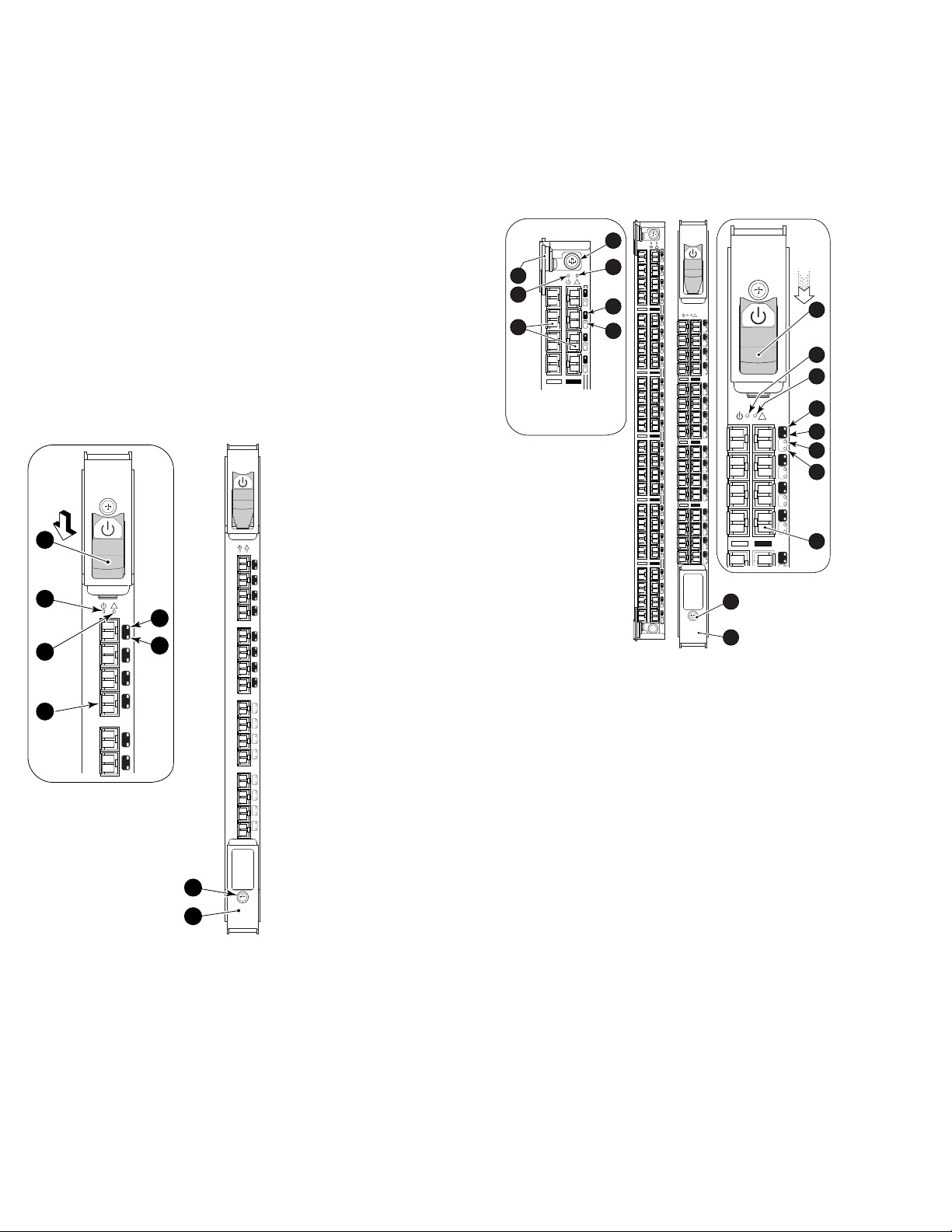
FC4–16 Port Blade components
Figure 1 identifies FC4–16 blade components and the port numbering
scheme. P
Figure 1 FC4–16 components
Callouts
1. On/Off switch (On position)
2. Power LED
3. Status LED
4. Fibre Channel port
orts are numbered from 0 through 15 from bottom to top.
56-0000590-01 Rev A
1
56-0000590-01 Rev A
2
3
!
5
15
6
14
13
12
4
11
10
!
15
14
13
12
11
10
9
8
7
6
5
4
3
2
1
0
FC4
16
7
8
25027a
5. Port speed LED
6. Por t status LED
7. Thumb screw
8. Ejector
FC4–32 and FC4–4
Figure 2 identif
numbering schem
ies FC4–32 and FC4–48 blade components and port
es.
8 Port Blade components
For the FC4–32, ports are numbered from 0 through 15 from bottom to
top on the left s
et of ports, and 16 through 31 from bottom to top on
the right set of ports.
For the FC4–48
, ports are numbered from 0 through 23 from bottom to
topontheleftsetofportsand24through47frombottomtotopon
the right set
1
2
3
of ports.
!
47
23
46
22
45
21
44
20
4
!
47
23
5
6
7
46
22
45
21
44
20
!
43
31
19
15
42
30
18
14
41
29
17
13
40
28
16
12
39
27
15
11
38
26
14
10
37
25
13
9
36
24
12
8
35
23
11
7
34
22
10
6
33
21
9
5
32
20
8
4
31
19
7
3
30
18
6
2
29
17
5
1
28
16
4
0
27
3
26
FC4
2
32
25
1
24
0
!
8
10
11
12
13
31
14
15
15
30
14
16
29
13
28
12
17
27
9
25225a
Figure 2 FC4–48 (left) and FC4–32 (right) components
Callouts
Off switch (on position)
1. On/
/Off Switch (Off position)
10. On
2. FC4–48 power LED 11. FC4–32 power LED
3. FC4–48 Fibre Channel ports
umb screw
4. Th
12. FC4–32 status LED
C4–32 port speed LED
13. F
5. FC4–48 status LED 14. FC4–32 port status LED
6. FC4–48 port status LED
15. Port speed LED for FC4–32
(for FC4–32 this LED indicates
the port speed for the left port)
rt status LED for FC4-32
7. Po
FC4-48 (for FC4–32 and
and
–48, this LED indicates the
FC4
t status for the left port)
por
ort status LED for FC4–32
16. P
FC4–48 (for FC4–32 and
and
–48, this LED indicates the
FC4
t status for the left port)
por
8. Thumb screw 17. Fibre Channel port
9. Ejector
Page 2
Page 3

Time and items required for install
The installatio
• 4Gb SAN Director
• Minimum of two P
• Electrostati
• Replacement f
Director)
• Workstation
• Phillips scr
• SFP transce
n takes less than 10 minutes. Obtain the following items:
Port Blade
ower Supplies installed in the SAN Director
c Discharge (ESD) grounding strap
iller panel for each empty slot (ships with the SAN
computer
ew driver
iversandopticalcables(asneeded)
Remove the filler panel
b. Pull on the top an
d bottom pulling tabs to slide the filler panel
out of the chassis.
IMPORTANT:
Remove a filler panel only when installing a port blade. Any
slot that is not occupied by a port blade requires a filler panel to
ensure correct cooling of the chassis and protection from dust.
Installing the por t blade
The FC4–16 and FC4–32 port blades use the same procedure.
However, the FC4–48 differs slightly in design. Port blade-specific
instructions are called out where applicable, as follows:
Remove the fi
see Figure 3
ller panel, if installed. There are three filler panel types,
:
!
!
5
4
3
2
1
!
5
6
-
0
0
0
0
5
9
0
-
0
1
R
e
v
A
!
!
15
14
I O I O I RS - 232
13
I O I O I RS - 232
12
11
10
k
n
b
i
L
M
0
0
1
/
0
1
9
P
s
C
/
k
n
b
e
i
L
v
i
M
t
c
0
A
0
1
/
8
0
1
P
C
e
v
i
t
c
A
7
6
5
4
3
2
1
0
CP4
CP4
FC4
16
-60 Hz
0
0 VAC 12A 5
200-24
0
1
9
8
7
6
5
6
-
0
0
0
0
5
9
0
-
0
1
R
e
v
A
!
15
14
13
12
11
10
9
8
7
s
/
6
5
4
3
2
1
0
FC4
16
-60 Hz
AC 12A 50
-240 V
200
Y 4
ER SUPPL
POW
Y 3
PL
UP
S
ER
POW
!
!
Y 2
ER SUPPL
POW
!
!
Y 1
Y 1
PL
PL
ER SUP
ER SUP
OW
OW
P
P
1
7
6
5
2
3
4
25043a
Figure 3 Removing three different filler panel types
Callouts
1. Filler panel with handle
2. Captive screws (2)
5. Ejectors (2)
6. Pull tabs (2)
3. Handle 7. Filler panel with pull tabs
ller panel with ejectors
4. Fi
1. To remove a filler panel with a handle:
a. Unscrew the two captive screws securing the filler panel.
b. Grasp the handle in the middle of the filler panel and remove.
2. To remove a filler panel with ejectors:
a. Push in the yellow tab on each ejector.
b. Lever both ejectors all the way open, and remove the filler
panel from the chassis.
3. To remove a filler panel with p ull tabs:
a. Unscrew the top and bottom captive screws on the filler panel.
CAUTION:
Wear a ground
ed ESD strap when handling the port blade.
The 4/256 SAN Director chassis has a grounding connection
above the power connectors.
1. Locate an appropriate slot. Install port blades in slots 1 through 4;
and 7 through 10.
NOTE:
For details on supported mixed blade configurations, refer to
the
HP StorageWorks SAN Director installation guide
.
2. Orient the port blade so that the ports are at the front of the chassis
and the flat side of the port blade is on the left, see Figure 4.Hold
the port blade by the edges of the metal pan. Do not use the
ejectors to hold the port blade.
CAUTION:
ure to gently apply pressure to the port blade, in order
Make s
perly seat the card all the way into the slot. Applying
to pro
sive pressure may damage the VHDM connectors on the
exces
tor’s backplane.
Direc
1
!
!
6
5
4
3
2
1
!
5
6
-
00
0
0
59
0
-0
1
R
e
v
A
!
!
5
1
4
1
I O I O I RS - 232
3
1
I O I O I RS - 232
2
1
1
1
0
1
s
/
k
b
in
L
M
0
0
1
/
0
1
9
P
s
C
/
k
b
e
in
L
iv
M
t
c
0
A
0
1
/
8
0
1
P
e C
iv
t
c
A
7
6
5
4
3
2
1
0
CP4
CP4
FC4
16
0 VA
-24
200
0-60 Hz
C 12A 5
200-240 VA
7
C 12A 50-60 Hz
!
!
0
1
9
8
POWER SUPPLY 4
5
6
-
0
0
00
5
9
0
-01
R
ev A
!
!
!
5
1
4
1
3
1
2
1
ER SUPPLY 3
1
1
POW
0
1
9
8
!
7
!
6
5
4
3
ER SUP
2
POW
1
0
4
FC
32
!
FC4
32
FC4
!
16
ER SUPPLY 1
ER SUPPLY 1
POW
POW
2
PLY 2
5
6
-
0
0
0
0
5
90-0
1
Rev A
!
5
1
4
1
3
1
2
1
3
1
1
0
1
9
8
7
6
5
4
3
2
1
0
FC4
16
4
25217a
Figure 4 Installing a FC4–16 or FC4–32 Port Blade
Callouts
1. SAN Director chassis
2. FC4-16
3. On/Off slider switch
Ejector
4.
Page 3
Page 4

3. If installing th
For FC4–16 and FC
a. Open the ejector
eFC4–48,gotostep4.
4–32 models (see Figure 4).
s to approximately 45 degrees.
b. Align the flat side of the port blade inside the upp er and lower
rail guides in the slot, and slide the port blade into the slot,
with slight pr
4. For FC4–48 mod
a. Adjust the ej
b. Align the fla
rail guides
c. Slide the po
1
essure to the left, until it is firmly seated.
els (see Figure 5):
ectors to the open position.
t side of the port blade inside the upper and lower
in the slot.
rt blade into the slot, until it is firmly seated.
1
!
!
8
7
6
5
5
6-0
0
00
590
-
0
1
R
ev
4
A
3
2
5
6
-00
0
0
59
0-
01
R
e
v
A
!
5
1
4
1
3
1
2
1
1
1
0
1
9
8
7
6
5
4
3
2
1
0
FC
16
0 VAC
-24
200
!
5
1
4
1
3
1
!
2
1
!
1
1
0
1
I O I O I RS - 232
9
8
I O I O I RS - 232
7
6
s
k
Lin
5
100 Mb/
10/
s
k
Lin
4
Active CP
100 Mb/
10/
Active CP
3
2
1
0
4
FC
16
CP4
4
CP4
50-60
AC 12A
0 V
200-24
50-60 Hz
12A
!
!
0
1
9
4
FC
32
4
FC
32
Hz
4
Y
L
PP
SU
R
E
W
O
P
!
!
3
Y
PL
UP
POWER S
!
!
PLY 2
SUP
POWER
!
!
Y 1
Y 1
PL
PL
POWER SUP
POWER SUP
2
!
7
4
3
2
6
4
2
2
5
4
1
2
4
4
0
2
3
4
9
1
2
4
8
1
1
4
7
1
0
4
6
1
9
3
5
1
8
3
4
1
7
3
3
1
6
3
2
1
5
3
1
1
4
3
0
1
3
3
9
2
3
8
1
3
7
0
3
6
9
2
5
8
2
4
7
2
3
6
2
2
5
2
1
4
2
0
3
4
7. Tighten the thum
b screw inside each handle using the Phillips
screw driver.
IMPORTANT:
Theupperandlowerthumbscrewsmustbecompletely
tightened, and the upper and lower ejectors must be in the
closed position for the FC4–48 to power on.
8. If installing the FC4–48, go to step 9.
For FC4–16 and FC4–32 models (see Figure 4):
a. To power on the port blade, move up the slider switch in the
top ejector.
b. Verify that the slider switch covers the thumbscrew.
9. For the FC4–48:
Verify that the power LED on the port blade displays a steady
green light (it might require a few seconds to turn on). If it does
not turn on
thumb scr
The LED pa
diagnost
10. Install
11. Refer to
, ensure that the port blade is firmly seated and that the
ews are tight.
tterns might temporarily change during POST and other
ic tests.
SFP transceivers and cables in the port blade, as required.
the HP StorageWorks SAN Director installation guide for
different ways to manage cables, including:
• Routing directly down, through the cable management tray,
d of across adjacent blades to keep LEDs visible.
instea
•Insta
•Insta
lling cable channels on the sides of the cabinet
lling patch panels
IMPORTANT:
Disassembling any part of the port blades voids the part
warranty and regulatory certifications. There are no
user-serviceable parts inside the port blade.
25223a
e 5 Installing an FC4–48 Port Blade
Figur
Callouts
per ejector
N Director chassis
1. SA
2. FC4–48
nstalling the FC4–48, go to step 6.
5. If i
FC4–16 and F C4–32 models (see Figure 4).
For
a. Pus
b. Ve
6.F
A
h the handles toward the center of the port blade, closing
eejectors.
th
rify that the handle’s levering action properly seats the port
ade in the slot.
bl
or the FC4–48:
djust the ejectors to the closed position (see Figure 5) by pulling
3. Up
4. Lower ejector
them away from the center of the port blade.
Waste Electrical and Electronic
Equipment ( WEEE) directive
Page 4
 Loading...