

HP A7990A Hardware Reference Manual

HP StorageWorks
DC SAN Backbone Director
hardware reference guide
Part number: 5697-7346
First edition: September 2008

Legal and notice information
© Copyright 2008 Hewlett-Packard Development Company, L.P.
© Copyright 2008 Brocade Communications Systems, Incorporated
Hewlett-Packard Company makes no warranty of any kind with regard to this material, including, but not limited to, the implied warranties of
merchantability and fitness for a particular purpose. Hewlett-Packard shall not be liable for errors contained herein or for incidental or consequential
damages in connection with the furnishing, performance, or use of this material.
This document contains proprietary information, which is protected by copyright. No part of this document may be photocopied, reproduced, or
translated into another language without the prior written consent of Hewlett-Packard. The information is provided “as is” without warranty of any
kind and is subject to change without notice. The only warranties for HP products and services are set forth in the express warranty statements
accompanying such products and services. Nothing herein should be construed as constituting an additional warranty. HP shall not be liable for
technical or editorial errors or omissions contained herein.
Product names mentioned herein may be trademarks of their respective companies.
Microsoft, Windows, Windows NT, and Windows XP are U.S. registered trademarks of Microsoft Corporation.
DC SAN Backbone Director hardware reference guide

Contents
About this guide. . . . . . . . . . . . . . . . . . . . . . . . . . . . . . . . . . . . . . . . . . . . . . . . . . . . . . . 9
Intended audience . . . . . . . . . . . . . . . . . . . . . . . . . . . . . . . . . . . . . . . . . . . . . . . . . . . . . . . . . . . . . . . 9
Related documentation . . . . . . . . . . . . . . . . . . . . . . . . . . . . . . . . . . . . . . . . . . . . . . . . . . . . . . . . . . . . 9
Document conventions and symbols . . . . . . . . . . . . . . . . . . . . . . . . . . . . . . . . . . . . . . . . . . . . . . . . . . 10
Rack stability . . . . . . . . . . . . . . . . . . . . . . . . . . . . . . . . . . . . . . . . . . . . . . . . . . . . . . . . . . . . . . . . . . 11
HP technical support . . . . . . . . . . . . . . . . . . . . . . . . . . . . . . . . . . . . . . . . . . . . . . . . . . . . . . . . . . . . . 11
Customer self repair . . . . . . . . . . . . . . . . . . . . . . . . . . . . . . . . . . . . . . . . . . . . . . . . . . . . . . . . . . . . . 11
Product warranties . . . . . . . . . . . . . . . . . . . . . . . . . . . . . . . . . . . . . . . . . . . . . . . . . . . . . . . . . . . . . . 11
Subscription service . . . . . . . . . . . . . . . . . . . . . . . . . . . . . . . . . . . . . . . . . . . . . . . . . . . . . . . . . . . . . 11
HP websites . . . . . . . . . . . . . . . . . . . . . . . . . . . . . . . . . . . . . . . . . . . . . . . . . . . . . . . . . . . . . . . . 11
Documentation feedback . . . . . . . . . . . . . . . . . . . . . . . . . . . . . . . . . . . . . . . . . . . . . . . . . . . . . . . . . . 12
1 Overview . . . . . . . . . . . . . . . . . . . . . . . . . . . . . . . . . . . . . . . . . . . . . . . . . . . . . . . . 13
HP StorageWorks DC SAN Backbone Director Power Pack . . . . . . . . . . . . . . . . . . . . . . . . . . . . . . . . . . 13
Features . . . . . . . . . . . . . . . . . . . . . . . . . . . . . . . . . . . . . . . . . . . . . . . . . . . . . . . . . . . . . . . . . . . . . 13
Hardware components . . . . . . . . . . . . . . . . . . . . . . . . . . . . . . . . . . . . . . . . . . . . . . . . . . . . . . . . . . . 14
Port side of the DC Director. . . . . . . . . . . . . . . . . . . . . . . . . . . . . . . . . . . . . . . . . . . . . . . . . . . . . . 15
Non-port side of the DC Director . . . . . . . . . . . . . . . . . . . . . . . . . . . . . . . . . . . . . . . . . . . . . . . . . . 16
DC Director blades . . . . . . . . . . . . . . . . . . . . . . . . . . . . . . . . . . . . . . . . . . . . . . . . . . . . . . . . . . . . . . 17
High availability . . . . . . . . . . . . . . . . . . . . . . . . . . . . . . . . . . . . . . . . . . . . . . . . . . . . . . . . . . . . . . . . 17
Reliability . . . . . . . . . . . . . . . . . . . . . . . . . . . . . . . . . . . . . . . . . . . . . . . . . . . . . . . . . . . . . . . . . . . . 18
Serviceability . . . . . . . . . . . . . . . . . . . . . . . . . . . . . . . . . . . . . . . . . . . . . . . . . . . . . . . . . . . . . . . . . . 18
Software features . . . . . . . . . . . . . . . . . . . . . . . . . . . . . . . . . . . . . . . . . . . . . . . . . . . . . . . . . . . . . . . 18
Security . . . . . . . . . . . . . . . . . . . . . . . . . . . . . . . . . . . . . . . . . . . . . . . . . . . . . . . . . . . . . . . . . . . . . . 19
Network manageability . . . . . . . . . . . . . . . . . . . . . . . . . . . . . . . . . . . . . . . . . . . . . . . . . . . . . . . . . . . 19
Optional software licenses . . . . . . . . . . . . . . . . . . . . . . . . . . . . . . . . . . . . . . . . . . . . . . . . . . . . . . . . . 20
Optional hardware kits . . . . . . . . . . . . . . . . . . . . . . . . . . . . . . . . . . . . . . . . . . . . . . . . . . . . . . . . . . . 21
2 Installation. . . . . . . . . . . . . . . . . . . . . . . . . . . . . . . . . . . . . . . . . . . . . . . . . . . . . . . . 23
Time and items required . . . . . . . . . . . . . . . . . . . . . . . . . . . . . . . . . . . . . . . . . . . . . . . . . . . . . . . . . . 23
Site preparation, unpacking the DC Director . . . . . . . . . . . . . . . . . . . . . . . . . . . . . . . . . . . . . . . . . . . . 24
Items included with the DC Director. . . . . . . . . . . . . . . . . . . . . . . . . . . . . . . . . . . . . . . . . . . . . . . . . . . 25
Installing the DC Director in the 14U Rack Mount Kit. . . . . . . . . . . . . . . . . . . . . . . . . . . . . . . . . . . . . . . 26
14U Rack Mount Kit parts list . . . . . . . . . . . . . . . . . . . . . . . . . . . . . . . . . . . . . . . . . . . . . . . . . . . . 26
Attaching the shelf brackets. . . . . . . . . . . . . . . . . . . . . . . . . . . . . . . . . . . . . . . . . . . . . . . . . . . . . . 28
Removing the chassis door . . . . . . . . . . . . . . . . . . . . . . . . . . . . . . . . . . . . . . . . . . . . . . . . . . . . . . 30
Installing the chassis in the cabinet. . . . . . . . . . . . . . . . . . . . . . . . . . . . . . . . . . . . . . . . . . . . . . . . . 30
Replacing the chassis door . . . . . . . . . . . . . . . . . . . . . . . . . . . . . . . . . . . . . . . . . . . . . . . . . . . . . . 32
Powering on the DC Director . . . . . . . . . . . . . . . . . . . . . . . . . . . . . . . . . . . . . . . . . . . . . . . . . . . . . . . 34
Port numbering. . . . . . . . . . . . . . . . . . . . . . . . . . . . . . . . . . . . . . . . . . . . . . . . . . . . . . . . . . . . . . . . . 34
Managing cables . . . . . . . . . . . . . . . . . . . . . . . . . . . . . . . . . . . . . . . . . . . . . . . . . . . . . . . . . . . . . . . 35
Using the optional HP StorageWorks DC SAN Backbone Director Inter-Chassis Link (ICL) cable kit . . . . . . . 35
3 Log in and configuration . . . . . . . . . . . . . . . . . . . . . . . . . . . . . . . . . . . . . . . . . . . . . . 41
Configuration overview . . . . . . . . . . . . . . . . . . . . . . . . . . . . . . . . . . . . . . . . . . . . . . . . . . . . . . . . . . . 41
Establish a serial connection and log on to DC Director. . . . . . . . . . . . . . . . . . . . . . . . . . . . . . . . . . . . . 41
Configure IP addresses . . . . . . . . . . . . . . . . . . . . . . . . . . . . . . . . . . . . . . . . . . . . . . . . . . . . . . . . . . . 42
Default IP addresses and password . . . . . . . . . . . . . . . . . . . . . . . . . . . . . . . . . . . . . . . . . . . . . . . . 43
Establish an Ethernet connection . . . . . . . . . . . . . . . . . . . . . . . . . . . . . . . . . . . . . . . . . . . . . . . . . . . . . 44
Customize a switch name . . . . . . . . . . . . . . . . . . . . . . . . . . . . . . . . . . . . . . . . . . . . . . . . . . . . . . . . . 44
Set the Domain ID. . . . . . . . . . . . . . . . . . . . . . . . . . . . . . . . . . . . . . . . . . . . . . . . . . . . . . . . . . . . . . . 44
Verify the Port Identifier (PID) mode and connect to the fabric. . . . . . . . . . . . . . . . . . . . . . . . . . . . . . . . . 45
Enable software licenses . . . . . . . . . . . . . . . . . . . . . . . . . . . . . . . . . . . . . . . . . . . . . . . . . . . . . . . . . . 45
Back up the configuration . . . . . . . . . . . . . . . . . . . . . . . . . . . . . . . . . . . . . . . . . . . . . . . . . . . . . . . . . 46
DC SAN Backbone Director hardware reference guide 3

4 Monitor system components . . . . . . . . . . . . . . . . . . . . . . . . . . . . . . . . . . . . . . . . . . . 47
Introduction . . . . . . . . . . . . . . . . . . . . . . . . . . . . . . . . . . . . . . . . . . . . . . . . . . . . . . . . . . . . . . . . . . . 47
Director blade . . . . . . . . . . . . . . . . . . . . . . . . . . . . . . . . . . . . . . . . . . . . . . . . . . . . . . . . . . . . . . . . . 47
Control Processor blade (CP8) . . . . . . . . . . . . . . . . . . . . . . . . . . . . . . . . . . . . . . . . . . . . . . . . . . . . . . 55
Core switch blade (CR8) . . . . . . . . . . . . . . . . . . . . . . . . . . . . . . . . . . . . . . . . . . . . . . . . . . . . . . . . . . 56
Power supply . . . . . . . . . . . . . . . . . . . . . . . . . . . . . . . . . . . . . . . . . . . . . . . . . . . . . . . . . . . . . . . . . . 58
Blower assembly . . . . . . . . . . . . . . . . . . . . . . . . . . . . . . . . . . . . . . . . . . . . . . . . . . . . . . . . . . . . . . . 59
WWN bezel (logo plate) and WWN card . . . . . . . . . . . . . . . . . . . . . . . . . . . . . . . . . . . . . . . . . . . . . 60
5 Installing Field-replaceable units (FRUs) . . . . . . . . . . . . . . . . . . . . . . . . . . . . . . . . . . . 63
Chassis door . . . . . . . . . . . . . . . . . . . . . . . . . . . . . . . . . . . . . . . . . . . . . . . . . . . . . . . . . . . . . . . . . . 64
Removing the chassis door . . . . . . . . . . . . . . . . . . . . . . . . . . . . . . . . . . . . . . . . . . . . . . . . . . . . . . 64
Replacing the chassis door . . . . . . . . . . . . . . . . . . . . . . . . . . . . . . . . . . . . . . . . . . . . . . . . . . . . . . 64
Cable management comb . . . . . . . . . . . . . . . . . . . . . . . . . . . . . . . . . . . . . . . . . . . . . . . . . . . . . . . . . 65
Removing a cable management comb . . . . . . . . . . . . . . . . . . . . . . . . . . . . . . . . . . . . . . . . . . . . . . 65
Replacing a cable management comb . . . . . . . . . . . . . . . . . . . . . . . . . . . . . . . . . . . . . . . . . . . . . . 65
Director blade . . . . . . . . . . . . . . . . . . . . . . . . . . . . . . . . . . . . . . . . . . . . . . . . . . . . . . . . . . . . . . . . . 66
Removing a Director blade . . . . . . . . . . . . . . . . . . . . . . . . . . . . . . . . . . . . . . . . . . . . . . . . . . . . . . 66
Replacing a Director blade . . . . . . . . . . . . . . . . . . . . . . . . . . . . . . . . . . . . . . . . . . . . . . . . . . . . . . 68
Director blade filler panel . . . . . . . . . . . . . . . . . . . . . . . . . . . . . . . . . . . . . . . . . . . . . . . . . . . . . . . . . 69
Removing a filler panel. . . . . . . . . . . . . . . . . . . . . . . . . . . . . . . . . . . . . . . . . . . . . . . . . . . . . . . . . 69
Replacing a filler panel . . . . . . . . . . . . . . . . . . . . . . . . . . . . . . . . . . . . . . . . . . . . . . . . . . . . . . . . 69
Control processor blade (CP8) . . . . . . . . . . . . . . . . . . . . . . . . . . . . . . . . . . . . . . . . . . . . . . . . . . . . . . 70
How to determine whether or not to replace a CP blade. . . . . . . . . . . . . . . . . . . . . . . . . . . . . . . . . . 70
Recording critical DC Director information . . . . . . . . . . . . . . . . . . . . . . . . . . . . . . . . . . . . . . . . . . . 70
Removing a control processor blade (CP8) . . . . . . . . . . . . . . . . . . . . . . . . . . . . . . . . . . . . . . . . . . . 72
Replacing a control processor blade (CP8) . . . . . . . . . . . . . . . . . . . . . . . . . . . . . . . . . . . . . . . . . . . 73
Verifying operation of the new CP blade . . . . . . . . . . . . . . . . . . . . . . . . . . . . . . . . . . . . . . . . . . . . 73
Core switch blade (CR8) . . . . . . . . . . . . . . . . . . . . . . . . . . . . . . . . . . . . . . . . . . . . . . . . . . . . . . . . . . 76
How to determine whether or not to replace a CP blade. . . . . . . . . . . . . . . . . . . . . . . . . . . . . . . . . . 76
Removing a core switch blade (CR8) . . . . . . . . . . . . . . . . . . . . . . . . . . . . . . . . . . . . . . . . . . . . . . . 77
Replacing a core switch blade (CR8) . . . . . . . . . . . . . . . . . . . . . . . . . . . . . . . . . . . . . . . . . . . . . . . 78
Power supply . . . . . . . . . . . . . . . . . . . . . . . . . . . . . . . . . . . . . . . . . . . . . . . . . . . . . . . . . . . . . . . . . . 78
Removing a power supply . . . . . . . . . . . . . . . . . . . . . . . . . . . . . . . . . . . . . . . . . . . . . . . . . . . . . . 79
Replacing a power supply . . . . . . . . . . . . . . . . . . . . . . . . . . . . . . . . . . . . . . . . . . . . . . . . . . . . . . 79
Blower assembly . . . . . . . . . . . . . . . . . . . . . . . . . . . . . . . . . . . . . . . . . . . . . . . . . . . . . . . . . . . . . . . 80
Removing a blower assembly . . . . . . . . . . . . . . . . . . . . . . . . . . . . . . . . . . . . . . . . . . . . . . . . . . . . 80
Replacing a blower assembly . . . . . . . . . . . . . . . . . . . . . . . . . . . . . . . . . . . . . . . . . . . . . . . . . . . . 80
WWN bezel (logo plate) and WWN card . . . . . . . . . . . . . . . . . . . . . . . . . . . . . . . . . . . . . . . . . . . . . 81
How to determine whether or not to replace a WWN card . . . . . . . . . . . . . . . . . . . . . . . . . . . . . . . 81
Removing the WWN bezel (logo plate) and WWN card . . . . . . . . . . . . . . . . . . . . . . . . . . . . . . . . . 83
Replacing the WWN bezel (logo plate) and WWN card. . . . . . . . . . . . . . . . . . . . . . . . . . . . . . . . . 84
SFPs and XFPs . . . . . . . . . . . . . . . . . . . . . . . . . . . . . . . . . . . . . . . . . . . . . . . . . . . . . . . . . . . . . . . . . 85
DC Director chassis . . . . . . . . . . . . . . . . . . . . . . . . . . . . . . . . . . . . . . . . . . . . . . . . . . . . . . . . . . . . . 86
Replacing the DC Director chassis door . . . . . . . . . . . . . . . . . . . . . . . . . . . . . . . . . . . . . . . . . . . . . 86
Verify need for replacing the chassis . . . . . . . . . . . . . . . . . . . . . . . . . . . . . . . . . . . . . . . . . . . . . . . 86
Record critical DC Director and SAN information . . . . . . . . . . . . . . . . . . . . . . . . . . . . . . . . . . . . . . 87
Disconnect from network and fabric . . . . . . . . . . . . . . . . . . . . . . . . . . . . . . . . . . . . . . . . . . . . . . . . 90
Remove components from chassis . . . . . . . . . . . . . . . . . . . . . . . . . . . . . . . . . . . . . . . . . . . . . . . . . 91
Install replacement chassis . . . . . . . . . . . . . . . . . . . . . . . . . . . . . . . . . . . . . . . . . . . . . . . . . . . . . . 91
Install components into new chassis . . . . . . . . . . . . . . . . . . . . . . . . . . . . . . . . . . . . . . . . . . . . . . . . 92
Configure new chassis serial number . . . . . . . . . . . . . . . . . . . . . . . . . . . . . . . . . . . . . . . . . . . . . . . 92
Verify correct operation of system . . . . . . . . . . . . . . . . . . . . . . . . . . . . . . . . . . . . . . . . . . . . . . . . . 94
Reconnect system to network and fabric . . . . . . . . . . . . . . . . . . . . . . . . . . . . . . . . . . . . . . . . . . . . . 96
Verify correct configuration of fabric . . . . . . . . . . . . . . . . . . . . . . . . . . . . . . . . . . . . . . . . . . . . . . . 97
Cable routing table . . . . . . . . . . . . . . . . . . . . . . . . . . . . . . . . . . . . . . . . . . . . . . . . . . . . . . . . . . . 98
A Technical specifications . . . . . . . . . . . . . . . . . . . . . . . . . . . . . . . . . . . . . . . . . . . . . 101
System architecture . . . . . . . . . . . . . . . . . . . . . . . . . . . . . . . . . . . . . . . . . . . . . . . . . . . . . . . . . . . . . 101
4

System size and weight . . . . . . . . . . . . . . . . . . . . . . . . . . . . . . . . . . . . . . . . . . . . . . . . . . . . . . . . . . 102
System blade and FRU weights. . . . . . . . . . . . . . . . . . . . . . . . . . . . . . . . . . . . . . . . . . . . . . . . . . . . . 103
Facility requirements . . . . . . . . . . . . . . . . . . . . . . . . . . . . . . . . . . . . . . . . . . . . . . . . . . . . . . . . . . . . 103
Power specifications . . . . . . . . . . . . . . . . . . . . . . . . . . . . . . . . . . . . . . . . . . . . . . . . . . . . . . . . . . . . 103
Power cords (Japan, Denan) . . . . . . . . . . . . . . . . . . . . . . . . . . . . . . . . . . . . . . . . . . . . . . . . . . . . . . 104
Power cords. . . . . . . . . . . . . . . . . . . . . . . . . . . . . . . . . . . . . . . . . . . . . . . . . . . . . . . . . . . . . . . . . . 104
Environmental requirements . . . . . . . . . . . . . . . . . . . . . . . . . . . . . . . . . . . . . . . . . . . . . . . . . . . . . . . 107
Fibre Channel port specifications . . . . . . . . . . . . . . . . . . . . . . . . . . . . . . . . . . . . . . . . . . . . . . . . . . . 107
Data transmission ranges. . . . . . . . . . . . . . . . . . . . . . . . . . . . . . . . . . . . . . . . . . . . . . . . . . . . . . . . . 108
General specifications. . . . . . . . . . . . . . . . . . . . . . . . . . . . . . . . . . . . . . . . . . . . . . . . . . . . . . . . . . . 108
B Intelligent blades . . . . . . . . . . . . . . . . . . . . . . . . . . . . . . . . . . . . . . . . . . . . . . . . . . 109
B-Series MP Router blade (FR4-18i) overview . . . . . . . . . . . . . . . . . . . . . . . . . . . . . . . . . . . . . . . . . . . 109
Installing the FR4-18i blade. . . . . . . . . . . . . . . . . . . . . . . . . . . . . . . . . . . . . . . . . . . . . . . . . . . . . 109
Items included with the FR4-18i blade . . . . . . . . . . . . . . . . . . . . . . . . . . . . . . . . . . . . . . . . . . . . . 109
Optional items. . . . . . . . . . . . . . . . . . . . . . . . . . . . . . . . . . . . . . . . . . . . . . . . . . . . . . . . . . . . . . 109
Installing and configuring the FR4-18i blade . . . . . . . . . . . . . . . . . . . . . . . . . . . . . . . . . . . . . . . . . 110
Insert the FR4-18i blade into the Director . . . . . . . . . . . . . . . . . . . . . . . . . . . . . . . . . . . . . . . . . 110
Configure FCIP and Fibre Channel Routing Services and enable the ports . . . . . . . . . . . . . . . . . . 111
Cable the FR4-18i blade . . . . . . . . . . . . . . . . . . . . . . . . . . . . . . . . . . . . . . . . . . . . . . . . . . . . 111
Recommendations for cable management . . . . . . . . . . . . . . . . . . . . . . . . . . . . . . . . . . . . . . . . 112
B-Series iSCSI Director (FC4-16IP) blade overview . . . . . . . . . . . . . . . . . . . . . . . . . . . . . . . . . . . . . . . 112
FC4-16IP supported features . . . . . . . . . . . . . . . . . . . . . . . . . . . . . . . . . . . . . . . . . . . . . . . . . . . . . . 112
Items included with the FC4-16IP Blade . . . . . . . . . . . . . . . . . . . . . . . . . . . . . . . . . . . . . . . . . . . . . . . 113
Optional items. . . . . . . . . . . . . . . . . . . . . . . . . . . . . . . . . . . . . . . . . . . . . . . . . . . . . . . . . . . . . . 113
Installing the FC4-16IP Blade . . . . . . . . . . . . . . . . . . . . . . . . . . . . . . . . . . . . . . . . . . . . . . . . . . . . . . 113
Installing the FC4-16IP Blade into the Director . . . . . . . . . . . . . . . . . . . . . . . . . . . . . . . . . . . . . . . . 113
Cabling the FC4-16IP Blade . . . . . . . . . . . . . . . . . . . . . . . . . . . . . . . . . . . . . . . . . . . . . . . . . . . . 113
Recommendations for cable management . . . . . . . . . . . . . . . . . . . . . . . . . . . . . . . . . . . . . . . . . . . 114
Configuring the FC4-16IP blade . . . . . . . . . . . . . . . . . . . . . . . . . . . . . . . . . . . . . . . . . . . . . . . . . . . . 115
Activating iSCSI. . . . . . . . . . . . . . . . . . . . . . . . . . . . . . . . . . . . . . . . . . . . . . . . . . . . . . . . . . . . . 115
Enabling the persistently disabled ports . . . . . . . . . . . . . . . . . . . . . . . . . . . . . . . . . . . . . . . . . . . . 115
Configuring the IP interface. . . . . . . . . . . . . . . . . . . . . . . . . . . . . . . . . . . . . . . . . . . . . . . . . . . . . 116
Creating the IP interface of the GbE port . . . . . . . . . . . . . . . . . . . . . . . . . . . . . . . . . . . . . . . . . 116
Adding IP routes on a GbE port (Optional). . . . . . . . . . . . . . . . . . . . . . . . . . . . . . . . . . . . . . . . 116
Verifying IP connectivity . . . . . . . . . . . . . . . . . . . . . . . . . . . . . . . . . . . . . . . . . . . . . . . . . . . . . 117
Adding ARP entries . . . . . . . . . . . . . . . . . . . . . . . . . . . . . . . . . . . . . . . . . . . . . . . . . . . . . . . . 117
Configuring an iSCSI interface . . . . . . . . . . . . . . . . . . . . . . . . . . . . . . . . . . . . . . . . . . . . . . . . . . 117
Creating iSCSI virtual targets . . . . . . . . . . . . . . . . . . . . . . . . . . . . . . . . . . . . . . . . . . . . . . . . . 117
Creating discovery domains and domain sets. . . . . . . . . . . . . . . . . . . . . . . . . . . . . . . . . . . . . . 118
Creating discovery domains . . . . . . . . . . . . . . . . . . . . . . . . . . . . . . . . . . . . . . . . . . . . . . . . . . 119
Creating/enabling discovery domain sets . . . . . . . . . . . . . . . . . . . . . . . . . . . . . . . . . . . . . . . . 119
Defining CHAP entries for iSCSI device authentication. . . . . . . . . . . . . . . . . . . . . . . . . . . . . . . . 120
Finalizing the iSCSI configuration . . . . . . . . . . . . . . . . . . . . . . . . . . . . . . . . . . . . . . . . . . . . . . 120
Configuring iSCSI protocol for each iSCSI port (Optional) . . . . . . . . . . . . . . . . . . . . . . . . . . . . . 121
C Regulatory compliance and safety notices . . . . . . . . . . . . . . . . . . . . . . . . . . . . . . . . . 123
Regulatory compliance notices . . . . . . . . . . . . . . . . . . . . . . . . . . . . . . . . . . . . . . . . . . . . . . . . . . . . . 123
Federal Communications Commission notice for Class A equipment . . . . . . . . . . . . . . . . . . . . . . . . . 123
Modifications . . . . . . . . . . . . . . . . . . . . . . . . . . . . . . . . . . . . . . . . . . . . . . . . . . . . . . . . . . . . 123
Cables. . . . . . . . . . . . . . . . . . . . . . . . . . . . . . . . . . . . . . . . . . . . . . . . . . . . . . . . . . . . . . . . . 123
Regulatory compliance identification numbers . . . . . . . . . . . . . . . . . . . . . . . . . . . . . . . . . . . . . 123
Laser device . . . . . . . . . . . . . . . . . . . . . . . . . . . . . . . . . . . . . . . . . . . . . . . . . . . . . . . . . . . . . 123
Laser safety warning . . . . . . . . . . . . . . . . . . . . . . . . . . . . . . . . . . . . . . . . . . . . . . . . . . . . . . . 123
Certification and classification information . . . . . . . . . . . . . . . . . . . . . . . . . . . . . . . . . . . . . . . . 124
Laser product label . . . . . . . . . . . . . . . . . . . . . . . . . . . . . . . . . . . . . . . . . . . . . . . . . . . . . . . . 124
International notices and statements . . . . . . . . . . . . . . . . . . . . . . . . . . . . . . . . . . . . . . . . . . . . . . . . . 125
Canadian notice (avis Canadien) . . . . . . . . . . . . . . . . . . . . . . . . . . . . . . . . . . . . . . . . . . . . . . . . 125
Class A equipment . . . . . . . . . . . . . . . . . . . . . . . . . . . . . . . . . . . . . . . . . . . . . . . . . . . . . . . . 125
DC SAN Backbone Director hardware reference guide 5

European Union regulatory notice. . . . . . . . . . . . . . . . . . . . . . . . . . . . . . . . . . . . . . . . . . . . . . 125
BSMI notice . . . . . . . . . . . . . . . . . . . . . . . . . . . . . . . . . . . . . . . . . . . . . . . . . . . . . . . . . . . . . 125
Japanese notice . . . . . . . . . . . . . . . . . . . . . . . . . . . . . . . . . . . . . . . . . . . . . . . . . . . . . . . . . . 126
Korean notices . . . . . . . . . . . . . . . . . . . . . . . . . . . . . . . . . . . . . . . . . . . . . . . . . . . . . . . . . . . 126
MIC statement (Republic of Korea) . . . . . . . . . . . . . . . . . . . . . . . . . . . . . . . . . . . . . . . . . . . . . 126
Korean Notice A and B . . . . . . . . . . . . . . . . . . . . . . . . . . . . . . . . . . . . . . . . . . . . . . . . . . . . . 126
Environmental regulation compliance . . . . . . . . . . . . . . . . . . . . . . . . . . . . . . . . . . . . . . . . . . . . . . . . 127
China RoHS . . . . . . . . . . . . . . . . . . . . . . . . . . . . . . . . . . . . . . . . . . . . . . . . . . . . . . . . . . . . . . . 127
Environmental Protection Use Period (EPUP) Disclaimer . . . . . . . . . . . . . . . . . . . . . . . . . . . . . . . 127
TS/HS Dual Language Sheet . . . . . . . . . . . . . . . . . . . . . . . . . . . . . . . . . . . . . . . . . . . . . . . . . 128
Safety guidelines . . . . . . . . . . . . . . . . . . . . . . . . . . . . . . . . . . . . . . . . . . . . . . . . . . . . . . . . . . . . . . 129
Electrostatic discharge recommendations . . . . . . . . . . . . . . . . . . . . . . . . . . . . . . . . . . . . . . . . . . . 129
Grounding methods . . . . . . . . . . . . . . . . . . . . . . . . . . . . . . . . . . . . . . . . . . . . . . . . . . . . . . . . . . 129
Battery replacement notice . . . . . . . . . . . . . . . . . . . . . . . . . . . . . . . . . . . . . . . . . . . . . . . . . . . . . 130
Taiwan battery recycling notice . . . . . . . . . . . . . . . . . . . . . . . . . . . . . . . . . . . . . . . . . . . . . . . . . . 130
Power cords . . . . . . . . . . . . . . . . . . . . . . . . . . . . . . . . . . . . . . . . . . . . . . . . . . . . . . . . . . . . . . . 131
Japanese power cord notice . . . . . . . . . . . . . . . . . . . . . . . . . . . . . . . . . . . . . . . . . . . . . . . . . . . . 131
D Port numbering templates . . . . . . . . . . . . . . . . . . . . . . . . . . . . . . . . . . . . . . . . . . . . 133
Index . . . . . . . . . . . . . . . . . . . . . . . . . . . . . . . . . . . . . . . . . . . . . . . . . . . . . . . . . . . . 141
Figures
1 Port side of the DC Director (sample configuration) . . . . . . . . . . . . . . . . . . . . . . . . . . . . . . . . . . . . 15
2 Non-port side of the DC Director (sample configuration) . . . . . . . . . . . . . . . . . . . . . . . . . . . . . . . . . 16
3 14U Rack Mount Kit contents . . . . . . . . . . . . . . . . . . . . . . . . . . . . . . . . . . . . . . . . . . . . . . . . . . . 27
4 Left and right shelf brackets installed on rails. . . . . . . . . . . . . . . . . . . . . . . . . . . . . . . . . . . . . . . . . 28
5 Shelf bracket and clip or retainer nut placement on cabinet rails . . . . . . . . . . . . . . . . . . . . . . . . . . . 29
6 Positioning the DC Director for installation in a cabinet. . . . . . . . . . . . . . . . . . . . . . . . . . . . . . . . . . 31
7 Attaching port side of chassis to rack rails . . . . . . . . . . . . . . . . . . . . . . . . . . . . . . . . . . . . . . . . . . 32
8 DC Director door aligned with chassis . . . . . . . . . . . . . . . . . . . . . . . . . . . . . . . . . . . . . . . . . . . . . 33
9 Inserting DC Director door on chassis ball studs. . . . . . . . . . . . . . . . . . . . . . . . . . . . . . . . . . . . . . . 33
10 ICL connectors on CR8 blade . . . . . . . . . . . . . . . . . . . . . . . . . . . . . . . . . . . . . . . . . . . . . . . . . . . 36
11 Inter-chassis link (ICL) connections (configuration 1) . . . . . . . . . . . . . . . . . . . . . . . . . . . . . . . . . . . . 37
12 Inter-chassis link (ICL) connections (configuration 2) . . . . . . . . . . . . . . . . . . . . . . . . . . . . . . . . . . . . 38
13 Inter-chassis link (ICL) connections (configuration 3) . . . . . . . . . . . . . . . . . . . . . . . . . . . . . . . . . . . . 39
14 Inter-chassis link (ICL) connections (configuration 4) . . . . . . . . . . . . . . . . . . . . . . . . . . . . . . . . . . . . 40
15 FC8-16 Director blade . . . . . . . . . . . . . . . . . . . . . . . . . . . . . . . . . . . . . . . . . . . . . . . . . . . . . . . . 48
16 FC8-32 Director blade . . . . . . . . . . . . . . . . . . . . . . . . . . . . . . . . . . . . . . . . . . . . . . . . . . . . . . . . 49
17 FC8-48 Director blade . . . . . . . . . . . . . . . . . . . . . . . . . . . . . . . . . . . . . . . . . . . . . . . . . . . . . . . . 50
18 FC10-6 Director blade . . . . . . . . . . . . . . . . . . . . . . . . . . . . . . . . . . . . . . . . . . . . . . . . . . . . . . . . 51
19 FC4-16IP Director blade . . . . . . . . . . . . . . . . . . . . . . . . . . . . . . . . . . . . . . . . . . . . . . . . . . . . . . . 52
20 FR4-18i Director blade . . . . . . . . . . . . . . . . . . . . . . . . . . . . . . . . . . . . . . . . . . . . . . . . . . . . . . . . 53
21 Control Processor blade (CP8). . . . . . . . . . . . . . . . . . . . . . . . . . . . . . . . . . . . . . . . . . . . . . . . . . . 55
22 Core switch blade (CR8). . . . . . . . . . . . . . . . . . . . . . . . . . . . . . . . . . . . . . . . . . . . . . . . . . . . . . . 57
23 Power supply . . . . . . . . . . . . . . . . . . . . . . . . . . . . . . . . . . . . . . . . . . . . . . . . . . . . . . . . . . . . . . 58
24 Blower assembly . . . . . . . . . . . . . . . . . . . . . . . . . . . . . . . . . . . . . . . . . . . . . . . . . . . . . . . . . . . . 59
25 WWN bezel (logo plate) . . . . . . . . . . . . . . . . . . . . . . . . . . . . . . . . . . . . . . . . . . . . . . . . . . . . . . 61
26 Removing or replacing a chassis door . . . . . . . . . . . . . . . . . . . . . . . . . . . . . . . . . . . . . . . . . . . . . 64
27 Removing or replacing the cable management comb . . . . . . . . . . . . . . . . . . . . . . . . . . . . . . . . . . . 65
28 Director blade (FC8-48 shown) . . . . . . . . . . . . . . . . . . . . . . . . . . . . . . . . . . . . . . . . . . . . . . . . . . 67
29 Director blade filler panel . . . . . . . . . . . . . . . . . . . . . . . . . . . . . . . . . . . . . . . . . . . . . . . . . . . . . . 69
30 Control processor blade (CP8) . . . . . . . . . . . . . . . . . . . . . . . . . . . . . . . . . . . . . . . . . . . . . . . . . . 73
31 Core switch blade (CR8). . . . . . . . . . . . . . . . . . . . . . . . . . . . . . . . . . . . . . . . . . . . . . . . . . . . . . . 77
32 Power supply . . . . . . . . . . . . . . . . . . . . . . . . . . . . . . . . . . . . . . . . . . . . . . . . . . . . . . . . . . . . . . 79
33 Blower assembly . . . . . . . . . . . . . . . . . . . . . . . . . . . . . . . . . . . . . . . . . . . . . . . . . . . . . . . . . . . . 81
34 WWN bezel (logo plate) and WWN card . . . . . . . . . . . . . . . . . . . . . . . . . . . . . . . . . . . . . . . . . . 84
35 Optical transceiver (SFP and XFP) extraction tool . . . . . . . . . . . . . . . . . . . . . . . . . . . . . . . . . . . . . . 85
36 B-Series MP Router blade (FR4-18i) components . . . . . . . . . . . . . . . . . . . . . . . . . . . . . . . . . . . . . 110
37 Class 1 laser product label . . . . . . . . . . . . . . . . . . . . . . . . . . . . . . . . . . . . . . . . . . . . . . . . . . . . 124
6

Tables
1 Document conventions . . . . . . . . . . . . . . . . . . . . . . . . . . . . . . . . . . . . . . . . . . . . . . . . . . . . . . . . . 10
2 Blades available for the DC Director . . . . . . . . . . . . . . . . . . . . . . . . . . . . . . . . . . . . . . . . . . . . . . . 17
3 Security features . . . . . . . . . . . . . . . . . . . . . . . . . . . . . . . . . . . . . . . . . . . . . . . . . . . . . . . . . . . . . 19
4 DC Director orderable software . . . . . . . . . . . . . . . . . . . . . . . . . . . . . . . . . . . . . . . . . . . . . . . . . . . 20
5 DC Director orderable hardware . . . . . . . . . . . . . . . . . . . . . . . . . . . . . . . . . . . . . . . . . . . . . . . . . . 21
6 Installation tasks, time and items required . . . . . . . . . . . . . . . . . . . . . . . . . . . . . . . . . . . . . . . . . . . . 23
7 Items supplied with the 14U rack mount kit (DC Director) . . . . . . . . . . . . . . . . . . . . . . . . . . . . . . . . . 26
8 Director blade LED descriptions . . . . . . . . . . . . . . . . . . . . . . . . . . . . . . . . . . . . . . . . . . . . . . . . . . . 54
9 CP blade LED descriptions . . . . . . . . . . . . . . . . . . . . . . . . . . . . . . . . . . . . . . . . . . . . . . . . . . . . . . 56
10 CR blade LED descriptions . . . . . . . . . . . . . . . . . . . . . . . . . . . . . . . . . . . . . . . . . . . . . . . . . . . . . . 58
11 Power supply LED descriptions. . . . . . . . . . . . . . . . . . . . . . . . . . . . . . . . . . . . . . . . . . . . . . . . . . . . 59
12 Blower assembly LED descriptions . . . . . . . . . . . . . . . . . . . . . . . . . . . . . . . . . . . . . . . . . . . . . . . . . 60
13 Messages that may indicate WWN card failure . . . . . . . . . . . . . . . . . . . . . . . . . . . . . . . . . . . . . . . 60
14 WWN bezel LED descriptions . . . . . . . . . . . . . . . . . . . . . . . . . . . . . . . . . . . . . . . . . . . . . . . . . . . . 61
15 WWN LED patterns . . . . . . . . . . . . . . . . . . . . . . . . . . . . . . . . . . . . . . . . . . . . . . . . . . . . . . . . . . . 82
16 Commands identifying the WWN card status . . . . . . . . . . . . . . . . . . . . . . . . . . . . . . . . . . . . . . . . . 82
17 WWN card related system log messages . . . . . . . . . . . . . . . . . . . . . . . . . . . . . . . . . . . . . . . . . . . . 82
18 Critical information checklist . . . . . . . . . . . . . . . . . . . . . . . . . . . . . . . . . . . . . . . . . . . . . . . . . . . . . 87
19 Cable routing table for DC Director (48 ports shown) . . . . . . . . . . . . . . . . . . . . . . . . . . . . . . . . . . . . 98
20 System architecture . . . . . . . . . . . . . . . . . . . . . . . . . . . . . . . . . . . . . . . . . . . . . . . . . . . . . . . . . . 101
21 System size and weight . . . . . . . . . . . . . . . . . . . . . . . . . . . . . . . . . . . . . . . . . . . . . . . . . . . . . . . 102
22 System FRU weights . . . . . . . . . . . . . . . . . . . . . . . . . . . . . . . . . . . . . . . . . . . . . . . . . . . . . . . . . . 103
23 Power specifications. . . . . . . . . . . . . . . . . . . . . . . . . . . . . . . . . . . . . . . . . . . . . . . . . . . . . . . . . . 104
24 Power cord types (international). . . . . . . . . . . . . . . . . . . . . . . . . . . . . . . . . . . . . . . . . . . . . . . . . . 105
25 Environmental requirements. . . . . . . . . . . . . . . . . . . . . . . . . . . . . . . . . . . . . . . . . . . . . . . . . . . . . 107
26 Supported cable speeds and distances . . . . . . . . . . . . . . . . . . . . . . . . . . . . . . . . . . . . . . . . . . . . .108
27 General specifications . . . . . . . . . . . . . . . . . . . . . . . . . . . . . . . . . . . . . . . . . . . . . . . . . . . . . . . . 108
28 B-Series MP Router blade (FR4-18i) components . . . . . . . . . . . . . . . . . . . . . . . . . . . . . . . . . . . . . . 110
DC SAN Backbone Director hardware reference guide 7

8

About this guide
This guide provides information about:
• Setting up and configuring the HP StorageWorks DC SAN Backbone Director
(short name, DC Director)
• Maintaining and operating the DC Director
• Installing FRUs
• Installing the optional Director blades
• Diagnostics and troubleshooting
• Technical specifications
• Regulatory compliance and safety notices
Intended audience
This guide is intended for system administrators and technicians with knowledge of:
• Storage area networks (SANs)
• HP StorageWorks Fibre Channel enterprise class switches (Directors)
Related documentation
The following documents provide related information:
• HP StorageWorks Fabric OS 6.x release notes
•
HP StorageWorks Fabbric OS 6.x administrator guide
You can find these and other documents from the Manuals page of the HP Business Support Center
website:
http://www.hp.com/support/manuals
In the Storage section, click Storage Networking. Then click HP StorageWorks DC SAN
Backbone Director to access the Manuals web page.
DC SAN Backbone Director hardware reference guide 9

Document conventions and symbols
Table 1 Document conventions
Convention Element
Blue text: Table 1 Cross-reference links and e-mail addresses
Blue, underlined text:
Website addresses
http://www.hp.com
Bold text
Italics text Text emphasis
Monospace text • File and directory names
Monospace, italic text • Code variables
Monospace, bold text Emphasized monospace text
• Key that are pressed
• Text typed into a GUI element, such as into a box
• GUI elements that are clicked or selected, such as menu and list
items, buttons, tabs, and check boxes
• System output
• Code
• Commands, their arguments, and argument values
• Command variables
WARNING! Indicates that failure to follow directions could result in bodily harm or death.
CAUTION: Indicates that failure to follow directions could result in damage to equipment or data.
IMPORTANT: Provides clarifying information or specific instructions.
NOTE: Provides additional information.
TIP: Provides helpful hints and shortcuts.
10

Rack stability
Rack stability protects personnel and equipment.
WARNING!
To reduce the risk of personal injury or damage to equipment:
• Extend leveling jacks to the floor.
• Ensure that the full weight of the rack rests on the leveling jacks.
• Install stabilizing feet on the rack.
• In multiple-rack installations, secure racks together.
• Extend only one rack component at a time. Racks may become unstable if more than one component is
extended.
HP technical support
For worldwide technical support information, see the HP support website:
http://www.hp.com/support/
Before contacting HP, collect the following information:
• Product model names and numbers
• Technical support registration number (if applicable)
• Product serial numbers
• Error messages
• Operating system type and revision level
• Detailed questions
Customer self repair
HP customer self repair (CSR) programs allow you to repair your StorageWorks product. If a CSR part
needs replacing, HP ships the part directly to you so that you can install it at your convenience. Some parts
do not qualify for CSR. Your HP-authorized service provider will determine whether a repair can be
accomplished by CSR.
For more information about CSR, contact your local service provider. For North America, see the CSR
website:
http://www.hp.com/go/selfrepair
Product warranties
For information about HP StorageWorks product warranties, see the warranty information website:
http://www.hp.com/go/storagewarranty
Subscription service
HP recommends that you register your product at the Subscriber's Choice for Business website:
http://www.hp.com/go/e-updates
After registering, you will receive e-mail notification of product enhancements, new driver versions,
firmware updates, and other product resources.
HP websites
For additional product information, see the following HP websites:
.
• http://www.hp.com
• http://www.hp.com/go/storage
• http://www.hp.com/service_locator
DC SAN Backbone Director hardware reference guide 11

• http://www.hp.com/support/manuals
• http://www.hp.com/support/downloads
Documentation feedback
HP welcomes your feedback.
To make comments and suggestions about product documentation, please send a message to
storagedocs.feedback@hp.com. All submissions become the property of HP.
12

1Overview
This chapter provides the following information:
• HP StorageWorks DC SAN Backbone Director Power Pack, page 13
• Features, page 13
• Hardware components, page 14
• DC Director blades, page 17
• High availability, page 13
• Reliability, page 18
• Serviceability, page 18
• Software features, page 18
• Security, page 19
• Network manageability, page 19
• Optional software licenses, page 20
• Optional hardware kits, page 21
HP StorageWorks DC SAN Backbone Director Power Pack
The HP StorageWorks DC SAN Backbone Director Power Pack model, part number AK857A, represents
the next generation of advanced Fibre Channel (FC) enterprise-class platforms used to intelligently
interconnect storage devices, hosts, and servers in a Storage Area Network (SAN).
The HP DC SAN Backbone Director is the highest-performance and highest-scalability enterprise-class
product offered by HP. It satisfies the most demanding Reliability, Availability, and Serviceability (RAS),
performance, and scalability requirements, while delivering investment protection, interoperability, and
fabric-based intelligence advantages.
NOTE: Throughout this document, the HP StorageWorks DC SAN Backbone Director is referenced using
its abbreviated name, DC Director.
Features
Key features of the DC Director include:
• Up to 384 ports in a single chassis, providing high port density for a scalable solution to drive
• Support for high-performance Director blades running at 1-, 2-, 4-, 8-, or 10-Gbps, enabling flexible
• Supports 1-, 2-, 4-, and 8-Gbps auto-sensing FC ports. Trunking technology groups up to eight ports to
• Dual-redundant CP blades (CP8) and core switch blades (CR8) provide high availability and enable
• Redundant and hot-swappable CP8 and CR8 blades, power supplies, blower assemblies, and WWN
• Inter-chassis linking (ICL) through CR8 blades.
• Universal ports self-configure as E_ports, F_ports, FL_ports, Ex_ports, and M_ports (mirror ports).
high-port-count SAN configurations.
system configuration
create high performance 64-Gbps ISL trunks between switches.
10 Gbps ports (FC10-6) are 10Gbps only.
non-disruptive software upgrades.
cards enable a high availability platform for mission critical SAN applications.
•10-Gbps (FC10-6) are E-Ports only.
• Ex_ports are supported only on the FR4-18i application blade.
DC SAN Backbone Director hardware reference guide 13

Hardware components
The DC Director features a modular and scalable mechanical construction that allows a wide range of
flexibility in installation, fabric design, and maintenance. The chassis may be mounted with the cables
facing the front of the equipment rack or to the rear, and consists of the following:
• Up to eight hot-swappable Director blade assemblies can be configured in a single chassis, delivering
up to 384 FC ports
• Two slots for CP blades (CP8):
• A single active CP8 blade can control all 384 ports in the chassis.
• The standby CP8 blade assumes control of the DC Director if the active CP fails.
• Two slots for core switch blades (CR8):
• CR8 blade interconnects all Director blades
• Two inter-chassis link (ICL) connectors per blade to connect to another DC Director chassis
• Both CR8 blades are active
• Modular hot-swappable Director blades:
• 16-port, 8-Gbps blades (FC8-16)
• 32-port, 8-Gbps blades (FC8-32)
• 48-port, 8-Gbps blades (FC8-48)
• 6-port, 10-Gbps blades (FC10-6)
• Modular hot-swappable application blades:
IMPORTANT: At the time of this document’s release, the FC4-16IP is not supported in the DC
Director. The FC4-16IP will be supported in a future version of Fabric OS.
• FR4-18i, 18-port (16 FC + 2 GbE), up to four blades per chassis, supporting FCR Services and FCIP
• FC4-16IP, 16-port (8 FC + 8 GbE), up to four blades per chassis, supporting iSCSI bridging)
• Modular hot-swappable field replaceable units (FRUs):
• Three blower assemblies
• Up to four power supplies
• At 240 VAC, two power supplies are required to provide redundancy, although the DC Director can
be fully powered with a single power supply at 240 VAC.
At 110 VAC, four power supplies are required when using the FR4-18i, or FC4-16IP blades.
• Two redundant WWN cards on the non-port side, to maintain chassis-specific information such as
WWNs, IP addresses, and summary status information for each Director blade and power supply
through LEDs
• 4Gb and 8Gb Small Form-factor Pluggable (SFP) optical transceivers (4Gb SFPs operate at 1Gb,
2Gb or 4Gb. 8Gb SFPs operate at 2Gb, 4Gb or 8Gb.)
• Extended Form-factor Pluggable (XFP) optical transceivers (10Gbps)
• All blades are serviced from the port side of the DC Director. Blowers, power supplies, and power
cables are serviced from the non-port side
• Improved cable management using a re-designed cable management comb and chassis door
• Constant intake andField-replaceable Unit (FRU) temperature monitoring
• Redundant AC primary power connections to ensure high availability. Each power supply has its own
connector, so the number of primary power connections varies from two to four.
14 Overview

Port side of the DC Director
NOTE: Airflow in the DC Director is from the non-port (non-cable) side to the port (cable) side and out the
exhaust vent.
Figure 1 shows a sample configuration of the port side of the DC Director.
1
2
3
4
5
25369a
Figure 1 Port side of the DC Director (sample configuration)
1Exhaust Vent 4FC8-48 Director blade
2 Core switch blade (CR8) 5 Cable management comb
3 CP blade (CP8)
DC SAN Backbone Director hardware reference guide 15

Non-port side of the DC Director
Figure 2 displays a sample configuration of the non-port side view of the DC Director.
1
2
3
Figure 2 Non-port side of the DC Director (sample configuration)
1 WWN bezel (logo plate) 3 Blower assembly
2Power supply
25370a
16 Overview

DC Director blades
Table 2 describes the Director, CP, and core switch blades that are available for the DC Director.
Table 2 Blades available for the DC Director
Description Name Function
DC Director CP
blade
DC Director core
switch blade
16-port 8-Gbps
Director blade
32-port 8-Gbps
Director blade
48-port 8-Gbps
Director blade
6-port 10-Gbps
Director blade
CP8 The CP8 blade provides for management of all other blades
in the DC Director. There are two CP8 blades for
redundancy. This CP blade is compatible only with the DC
Director.
CR8 The CR8 blade contains the ASICs for switching between
Director blades. Every Director blade connects to every core
switch blade. There are 384 total ports for Director blades.
Each core switch blade connects to 192 backplane ports.
Core switch blades have additional front port connectivity to
connect multiple chassis and backplane connections for the
storage server blade. This core switch blade is compatible
only with the DC Director.
FC8-16 A 16-port Director blade supporting 1, 2, 4, and 8Gbps port
speeds. This Director blade is compatible only with the
4/256 SAN Director or DC Director CP blades.
FC8-32 A 32-port Director blade supporting 1, 2, 4, and 8Gbps port
speeds.
FC8-48 A 48-port Director blade supporting 1, 2, 4, and 8Gbps port
speeds.
FC10-6 A 6-port Director blade supporting 10Gbps port speed.
Blade provides 10-Gbps ISLs. This Director blade is
compatible only with the 4/256 SAN Director or DC Director
CP blades.
B-Series MP Router
Blade (Fibre Channel
router blade)
HP StorageWorks
B-Series iSCSI
Director blade
(iSCSI bridge
blade)
High availability
The following features contribute to the DC Director high-availability design:
• Redundant, hot-swappable blades and FRUs
• Enhanced data integrity on all data paths
• Fabric Shortest Path First (FSPF) re-routing around failed links
• Integration with Simple Network Management Protocol (SNMP) managers
• Automatic CP failover
• Non-disruptive “hot” software code loads and activation
• Easy configuration, save, and restore
FR4-18i The FR4-18i blade integrates sixteen physical FC SFP ports
supporting FCR Services and two physical Gigabit Ethernet
(GbE) SFP ports supporting Fibre Channel Over IP (FCIP). The
two physical GbE ports can support up to sixteen virtual
E_ports.
FC4-16IP
The FC4-16IP blade enables bridging of iSCSI hosts to
Fibre Channel fabrics. It integrates eight Fibre Channel
optical SFP ports and 8 Gigabit Ethernet (GbE) copper
RJ-45 ports.
NOTE: At the time of this document’s release, the FC4-16IP is
not supported in the DC Director. The FC4-16IP will be
supported in a future version of Fabric OS.
DC SAN Backbone Director hardware reference guide 17

• Hot-swappable World Wide Name (WWN) cards
The high-availability software architecture of the DC Director provides a common framework for all
applications that reside on the system, allowing global and local states to be maintained through any
component failure. High-availability elements consist of the High Availability Manager, the heartbeat, the
fault/health framework, the replicated database, initialization, and software upgrade.
The High Availability Manager controls access to the standby CP blade, facilitates software upgrades,
prevents extraneous switchover activity, closes and flushes streams, provides flow control and message
buffering, and supports a centralized active and standby state.
Reliability
The DC Director uses the following error detection and correction mechanisms to ensure reliability of data:
• Data is protected by the Error Detection and Correction mechanism, which checks for encoder errors
and fault isolation (EDFI), such as cyclic redundancy checking (CRC), parity checking, checksum, and
illegal address checking
• Power-on self- test (POST)
• Dual CP Blades that enable hot, non-disruptive fast firmware upgrades
• Each CP Blade contains one serial port and two Ethernet ports, for management and for service.
Offline CP Blade diagnostics and remote diagnostics simplify troubleshooting. The standby CP Blade
monitors diagnostics to ensure it is operational, in case a failover is required.
• Bus monitoring and control of blades and other FRUs.
Serviceability
The DC Director provides the following features to enhance and ensure serviceability:
• Modular design with hot-swappable components
• Flash memory that stores two firmware images per CP Blade
• USB port on CP blades for all tasks that formerly required an FTP/SCP server, including software and
firmware upgrades.
• Non-volatile random-access memory (NVRAM), containing the serial number, serial number, revision
information, and part number information.
• Background health-check daemon
• Memory scrubber, self test, and bus ping to determine if a bus is not functioning
• RASlog messages
• SMI-S compliant
• Watchdog timers
• Status LEDs
• Predictive diagnostics analysis through Fabric Watch
• SNMP (including version 3) integration with higher-layer managers
Software features
The Fabric OS allows any Fibre Channel-compliant device to attach to the switches as long as it conforms
to the device login, name service, and related FC standards. Each operating environment requires that a
FC Host Bus Adapter (HBA) be available with a standards-compliant driver for correct interface to the
fabric.
Fabric OS consists of a set of embedded applications running on top of an embedded Linux operating
system kernel. These applications include:
• Name server
• Alias server
• Zone server
• Simple Network Management Protocol (SNMP) agent
18 Overview

• SMI-S compliant API
• Syslog auditing
• Reliable Commit Service (RCS)
• Network Time Protocol (NTP)
• Tasks to manage address assignment, routing, link initialization, fabric initialization, link shutdown, DC
Security
Table 3 highlights some of the key security features available for the DC Director running Fabric OS 6.0.0b
or later, and for other HP enterprise-class platforms running Fabric OS 5.2.0 or later. For details, contact
HP.
Table 3 Security features
Director shutdown, and the user interface.
Security Features
DH-CHAP Login banner
SSHv2 (using AES, 3DES, RSA) Monitoring of attempted security breaches
(via audit logging)
HTTPS (using AES) Monitoring of attempted security breaches
(via Fabric Watch Security Class)
SNPMv3 FC security policies: DCC and SCC
FC-SP Trusted Switch (FCS) for central security
management
Secure RPC Management access controls (SNMPv3,
Telnet, FTP, serial port, front panel)
Secure file copy (SCP) Hardware-enforced zoning by WWN
and/or domain/port ID
Telnet disable Default zoning
Telnet timeout RSCN suppression and aggregation
IP filters (block listeners) Configurable RSCN suppression by port
Secure passwords (centralized control
via RADIUS/CHAP)
Multiple User Accounts (MUAs). Up to
255.
Role-Based Access Controls (RBACs) Change tracking
Administrative domains/Virtual fabrics Firmware change alerts in Fabric Manager
Boot PROM password reset Persistent port disable
Password hardening policies Persistent domain ID
Upfront login in Web Tools E_port disable
NTPv3 (to synchronize timestamps)
Event auditing
Network manageability
The DC Director has a single domain and is managed as a single element with the optional Fabric
Manager (FM) Graphical User Interface (GUI) application. The DC Director responds to its own IP address
and appears as a separate entity to the Telnet protocol and SNMP.
All management interfaces, such as Telnet, Web Tools, standards compliant SMI-S, and Management
Server, support a “port N within blade M” naming scheme.
The DC Director supports SNMPv1 and SNPMv3. When SNMP devices send SNMP messages to a
management console running SAN management software, the information is stored in a Management
DC SAN Backbone Director hardware reference guide 19

Information Base (MIB). Fabric OS 6.x supports the latest Fibre Alliance Fibre Channel Management
(FCMGMT) and Storage Management Initiative (SMI) MIBs. These MIBs provide the SAN administrator
with information for monitoring the network. Refer to the Fabric OS MIB Reference Guide.
Optional software licenses
Table 4 lists the DC Director optional software kits.
Table 4 DC Director orderable software
Optional kit Part number
HP StorageWorks DC SAN Backbone Director ICL
Bundle Kit
This optional kit increases the number of ports using four
inter-chassis links (ICLs), or cables, that interconnect a
maximum of two DC Director chassis.
Each ICL Bundle Kit contains:
• Four, two meter copper cables
• Two ICL Licenses (one license required for each DC
Director)
HP StorageWorks Director FICON Cup LTU*
Provides Control Unit Port (CUP) management function
designed to allow mainframe applications to perform
configuration, monitoring, management and statistics
collection.
*Supported in XP Storage array environments only
Note: Contact your local HP representative for information
on exact Fabric OS versions supported.
HP StorageWorks MP Blade Performance
Extension LTU
AK862A
T4401A
T4427A
Activates the high performance extension services for either IP
or FC connectivity in the B-Series MP Router Blade (FR4-18i).
IP and FC extension services are mutually exclusive. This
option also includes the Encryption Services license.
HP StorageWorks Enterprise Edition version 5
Fabric Manager Software
Fabric Manager is a highly scalable, Java-based Graphical
User Interface (GUI) application that manages multiple
switches and multiple fabrics (up to eight) in real time.
Provides SAN administrators with an interface for
configuring, monitoring, and dynamic provisioning.
T4270A, Fabric Manager, v5.x Base, ten
domains
T4269A, Fabric Manager, v5.x Enterprise
200 domains, eight fabrics
T4272A, Fabric Manager, v4 Enterprise to
v5.x Enterprise upgrade
T4273A, Fabric Manager v5 base to v5.x
enterprise upgrade license
T4271A, Fabric Manager, v4 Base to v5.x
Base upgrade
20 Overview

Optional hardware kits
Table 5 lists the DC Director optional hardware kits.
Table 5 DC Director orderable hardware
Accessory Part number
Power Supply
HP StorageWorks DC SAN Backbone
Director Power Supply - Quantity 1
Director blades
HP StorageWorks SAN Director 16 Port
8Gb FC blade (FC8-16)
HP StorageWorks SAN Director 32 Port
8Gb FC blade (FC8-32)
HP StorageWorks SAN Director 48 Port
8Gb FC blade (FC8-48)
HP StorageWorks SAN Director 6 Port
10G b FC b la de ( FC 10 - 6)
HP StorageWorks B-Series Multi-protocol
(MP) Router blade (FR4-18i)
Optical transceivers
HP 4Gb Short Wave B-Series FC SFP
1 Pack
AK863A
AK858A
AK859A
AK860A
AK861A
AG461A
AJ715A
HP 4Gb Long Wave B-Series FC SFP
1 Pack - 10km
HP 8Gb Short Wave B-Series FC SFP+ 1
Pack
HP BLc 10Gb SR XFP Opt Kit 443756-B21
HP BLc 10Gb LR XFP O p t Kit 443757-B21
HP 8Gb Long Wave B-Series FC SFP+ 1
Pack - 10km
AK870A
AJ716A
AJ717A
Optical cables (LC-LC type cables)
HP 2 m Multi-mode OM2 LC/LC Fibre
Channel Cable
HP 5 m Multi-mode OM2 LC/LC Fibre
Channel Cable
HP 15 m Multi-mode OM2 LC/LC Fibre
Channel Cable
221692-B21
221692-B22
221692-B23
DC SAN Backbone Director hardware reference guide 21

Table 5 DC Director orderable hardware (continued)
Accessory Part number
HP 30 m Multi-mode OM2 LC/LC Fibre
Channel Cable
HP 50 m Multi-mode OM2 LC/LC Fibre
Channel Cable
Optical cables (LC-SC type cables)
HP 2 m Multi-mode OM2 LC/SC Fiber
Channel Cable
HP 5 m Multi-mode OM2 LC/SC Fiber
Channel Cable
HP 15 m Multi-mode OM2 LC/SC Fibre
Channel Cable
HP 30 m Multi-mode OM2 LC/SC Fibre
Channel Cable
HP 50 m Multi-mode OM2 LC/SC Fibre
Channel Cable
221692-B26
221692-B27
221691-B21
221691-B22
221691-B23
221691-B26
221691-B27
22 Overview

2Installation
This chapter provides the following information:
• Time and items required, page 23
• Site preparation, unpacking the DC Director, page 24
• Items included with the DC Director, page 25
• Installing the DC Director in the 14U Rack Mount Kit, page 26
• Powering on the DC Director, page 34
• Port numbering, page 34
• Managing cables, page 35
• Using the optional HP StorageWorks DC SAN Backbone Director Inter-Chassis Link (ICL) cable kit,
page 35
Time and items required
You can set up and install the DC Director in the following ways:
• As a standalone unit on a flat surface.
• In a 19-in. Electronic Industries Association (EIA) cabinet, using the 14U Rack Mount Kit (ships with your
DC Director).
Table 6 describes the main installation and setup tasks and the estimated time required for each, based
on a fully populated DC Director (384 FC ports). Configurations with fewer ports require less time.
These time estimates assume a prepared installation site and appropriate power and network
connectivity.
Table 6 Installation tasks, time and items required
Installation task Time estimate Items required
Site preparation and unpacking DC
Director
Installing rack mount kit 30 minutes See ”Installing the DC Director in the 14U
Mounting and securing DC Director in
rack
Installing power cables and powering
on the DC Director
Installing SFP and XFP (10-Gbps) optical
transceivers
Attaching fiber optic cables, cable ties,
and cable guides
30 minutes 1/2-in. socket wrench (to remove pallet
bolts)
#2 Phillips screwdriver
(for cable management comb)
Pallet jack
Hydraulic lift or assisted lift, able to raise to
a minimum of 55 in. (140 cm), with a
minimum capacity of 113 kg (250 lb). The
DC Director weighs 104 kg (228 lb) with
eight FC8-48 port cards installed (384
ports).
30 minutes
20 minutes Power cables and serial cable (provided in
30 minutes SFP and XFP (10Gbps) optical transceivers
60 minutes Fiber optic cables, cable ties, and pillars
Rack Mount Kit” on page 26.
the DC Director accessory kit)
DC SAN Backbone Director hardware reference guide 23

Table 6 Installation tasks, time and items required (continued)
Installation task Time estimate Items required
Establishing serial connection, logging
on to DC Director, and configuring IP
addresses
Installing Ethernet cable(s) and
configuring the DC Director name,
policies, domain ID, PIDs, or additional
system parameters
10 minutes Serial cable (provided in the DC Director
accessory kit)
Workstation computer with a serial port or
terminal server port and a terminal
emulator application (such as
HyperTerminal)
Ethernet IP addresses for the DC Director (1)
and for each CP blade and core switch
blade (2): total three addresses
20 minutes Ethernet cabling (optional) for Telnet access
All other configuration parameters optional
Refer to the HP StorageWorks Fabric OS
6.x administrator guide for Port Identifier
(PID) information.
Site preparation, unpacking the DC Director
IMPORTANT: See ”Regulatory compliance and safety notices” on page 123 for important safety
guidelines before setting up your DC Director.
The following steps are required to ensure correct installation and operation:
1. Provide a space that is 14 rack units (14U) high, 61.29 cm (24.09 in.) deep, and 43.74 cm (17.22 in.).
1U is equal to 4.45 cm (1.75 in.)
2. Plan to install the DC Director with the non-port side facing the aisle. The DC Director can be installed
facing either direction, if serviceability and cooling requirements are met.
3. Plan for cable management before installing the chassis (”Managing cables” on page 35).
Cables can be managed in a variety of ways, such as by routing cables below the chassis, to either
side of the chassis, through cable channels on the sides of the cabinet, or by using patch panels.
4. Ensure that dedicated electrical branch circuits with the following characteristics are available:
• 200 – 240 VAC, 50–60 Hz (two branch circuits)
• 110 - 120 VAC, 50-60 Hz (up to four branch circuits)
• One power cable per power supply is required
• Protected by a circuit breaker in accordance with local electrical codes
• Supply circuit, line fusing, and wire size adequate to the electrical rating on the chassis nameplate
• Location close to the chassis and easily accessible
• Grounded outlets installed by a licensed electrician, compatible with the power cords
TIP: To maximize fault tolerance, connect each power cord to a separate power source.
5. Ensure that the air intake and exhaust vents have a minimum of 2 in. of airspace.
6. Ensure that the air temperature on the air intake side is less than 40° Celsius (104° Fahrenheit) during
operation.
CAUTION: A fully populated DC Director (eight FC8-48 port cards, 384 ports) weighs approximately
104 kg (228 lbs) and requires a hydraulic or assisted lift to install it.
24 Installation

7. Remove the upper portion of the packing crate while the DC Director is still in the shipping area, to
reduce clutter at the installation site:
a.
Remove the straps securing the carton to the pallet.
b. Lift the top of the crate off the pallet. Leave the foam on top of the chassis to hold the kits in place
during transportation to the installation area. Save the shipping crate and related items for any
future shipping requirements.
8. Transport the chassis on the pallet to the installation area, using a pallet jack or other assisted lift. The
plastic pallet cannot fit through doorways that are less than 91 cm (36 in.) wide.
9. Remove the 14U rack mount kit, accessory kit, packing foam, and anti-static plastic from the chassis
and set aside.
10. Remove the chassis door from the DC Director. See ”Removing the chassis door” on page 30.
11 . Remove the cable management comb. See ”Removing a cable management comb” on page 65.
12 . Position the pallet so that the bottom of the chassis is level with the installation surface.
13 . If the chassis is on a pallet jack or lift, stabilize the pallet jack or lift to prevent it from moving during the
transfer.
14. Unscrew the four bolts holding the DC Director to the pallet and remove the brackets.
15 . Gently slide the chassis onto the final installation surface, ensuring that it remains supported during the
transfer.
16. Ensure that the chassis is oriented so that the non-port side has access to intake air (cool).
17. Reinstall the cable management comb. See ”Replacing a cable management comb” on page 65.
18. Reinstall the chassis door. See ”Replacing the chassis door” on page 64.
Items included with the DC Director
The following items are included with the standard shipment of the DC Director:
• DC Director chassis, populated with:
• Two CP blades (CP8)
• Two Core switch blades (CR8)
• Blade slot filler panels (for slots not filled by a port, control processor, or core switch blade)
• Two power supplies and power supply filler panels
• Three Blower assemblies
• One WWN card and bezel
• One cable management comb
• Chassis door
• Accessory kit containing the following items:
• HP StorageWorks DC SAN Backbone Director quick start instructions
• ESD grounding straps
• Two AC power cords, 3 meters (one for each power supply)
• Two PDU power cords (one for each power supply)
• Two Power cord retainers
• RS-232 serial cable
• 14U rack mount kit (includes rear brackets and bottom support rails)
IMPORTANT: Order SFP transceivers separately. The DC Director 8Gb port blades support HP
transceivers labeled “B-Series FC SFP” only. Check http://www.hp.com
transceivers.
for more information on supported
DC SAN Backbone Director hardware reference guide 25

Installing the DC Director in the 14U Rack Mount Kit
Allow approximately one hour to unpack and install your DC Director using the 14U Rack Mount Kit
supplied with your unit. Obtain the following tools:
• Torque wrench with #2 Phillips screwdriver tip
• Flathead screwdriver
• Hydraulic or assisted lift with a minimum raise of 55 in. (140 cm) and a minimum capacity of 250 lbs
(113 k g) .
CAUTION: A fully populated DC Director (eight FC8-48 port cards, 384 ports) weighs approximately
104 kg (228 lbs) and requires a hydraulic or assisted lift to install it.
14U Rack Mount Kit parts list
Table 7 and Figure 3 identify the hardware provided in the 4U rack mount kit that ships with your DC
Director.
Table 7 Items supplied with the 14U rack mount kit (DC Director)
Item Description Quantity
For all types of installations
A Left rack mount shelf bracket (rail brackets may differ from the illustration)
B Right rack mount shelf bracket (rail brackets may differ from the illustration)
C 10-32 x 5/8 inch (1.58 cm) panhead Phillips screw, washer (torque to 32 in.-lbs, 37
cm-kgs)
For cabinets that have rails with round holes
D10-32 clip nut
E 1/4-20 x 1/2 in. (1.27 cm) panhead Phillips screw, with lock washer (torque to 80
in.-lbs, 92 cm-kgs)
For cabinets that have rails with square holes
F10-32 retainer nut
G 1/4-20 x 1/2 in. (1.27 cm) panhead Phillips screw, with glue (torque to 80 in.-lbs, 92
cm-kgs)
H 0.375 in. (0.953 cm) alignment washer
1
1
6
6
16
6
16
16
26 Installation

I
Figure 3 14U Rack Mount Kit contents
26419a
DC SAN Backbone Director hardware reference guide 27
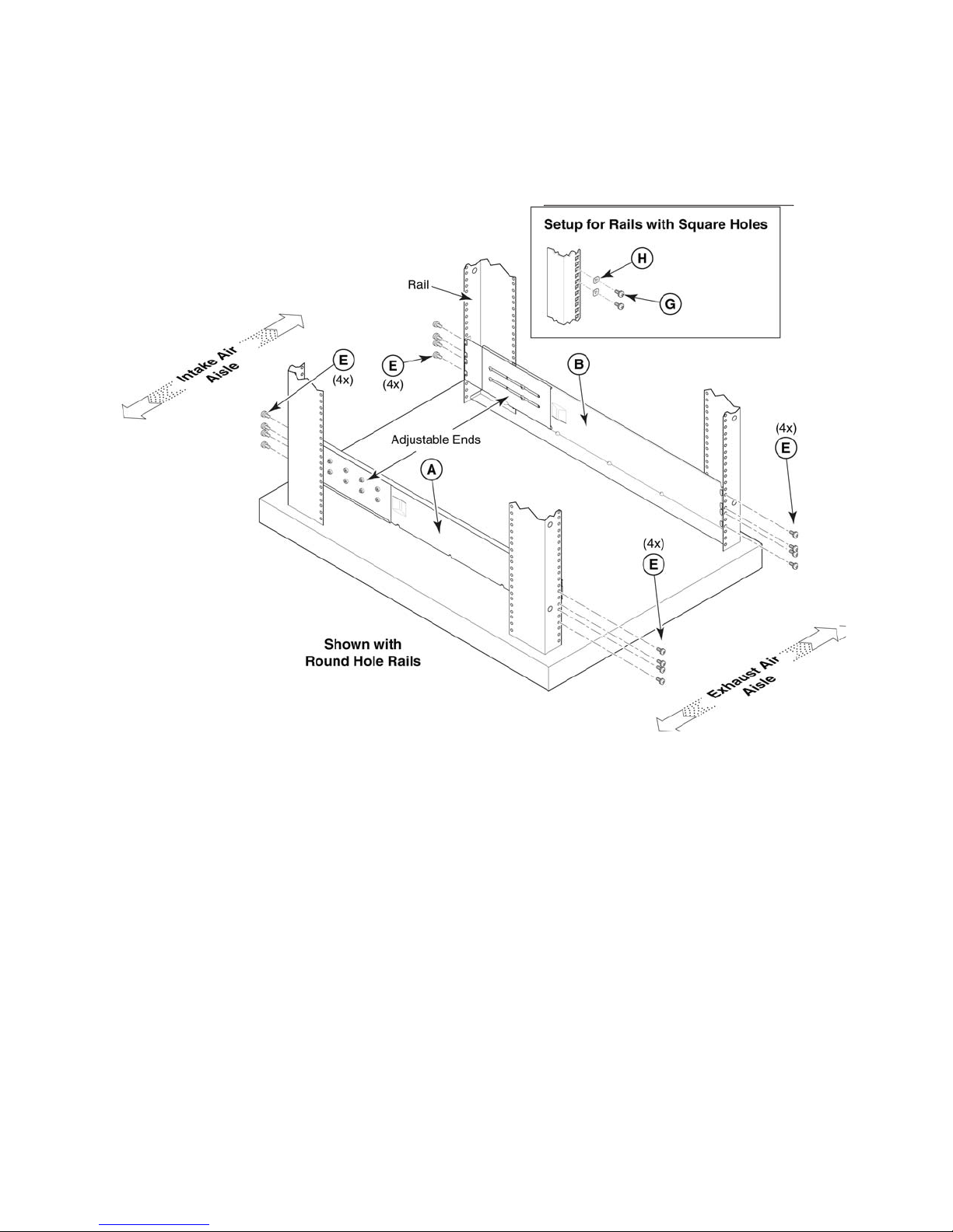
Attaching the shelf brackets
Attach the left and right rack mount shelf brackets (Items A and B) to the cabinet rails adjustable ends
installed on the side of the rack on the intake air aisle.
1. Locate the shelf brackets in the 14U Rack Mount Kit.
2. Locate and loosen the adjusting screws on the brackets (Figure 4, Items A and B) to allow for
adjustment to cabinet depth.
Figure 4 Left and right shelf brackets installed on rails
28 Installation

3. Position shelf brackets with adjustable ends on the intake aisle side of the cabinet (see Figure 5).
• For rails with round holes:
Position the left and right rack mount shelf brackets (Items A and B) and attach to the cabinet rails.
Use eight screws with lock washers per bracket (four on each end). Tighten the screws to a torque of
80 in.-lbs (92 cm-kgs).
• For rails with square holes:
Position the left and right rack mount shelf brackets (Items A and B) and attach to the cabinet rails.
Use eight screws with and alignment washers per bracket (four on each end). Tighten the screws to
a torque of 80 in.-lbs (92 cm-kgs).
Figure 5 Shelf bracket and clip or retainer nut placement on cabinet rails
NOTE: Standard EIA rails have holes in sets of three; spaces between the holes are 5/8 in., 5/8 in., and
1/2 in. (1.58 cm, 1.58 cm, 1.27 cm). If cables are to be routed down through the cable management
comb, allow space below the brackets for cable management.
26421a
DC SAN Backbone Director hardware reference guide 29

4. Tighten the adjusting screws on the rack mount shelf brackets to a torque of 32 in.-lbs (37 cm-kgs).
5. Attach the clip or retainer nuts to the vertical rails on the exhaust aisle side of the cabinet (Figure 5).
These clip nuts are used for securing the port side of the chassis to the rack rails using 10-32 x 5/8-inch
screws. Use three clips on each rail. Place the clips in optimum locations for securing the chassis to the
rails.
NOTE: Do not align the clip or retainer nuts with the top or bottom holes of the Brocade DCX mounting
bracket because the door will interfere with the screw heads.
• For rails with round holes:
Attach clip nuts (Item D) to each of the front rails.
• For rails with square holes:
Attach retainer nuts (Item F) to each of the front rails.
CAUTION: Use the screws specified in the procedure. Using longer screws can damage the chassis.
Removing the chassis door
See ”Removing the chassis door” on page 30 to uninstall the chassis door.
Installing the chassis in the cabinet
To install the DC Director in the cabinet:
CAUTION: A fully populated DC Director (eight FC8-48 port cards, 384 ports) weighs approximately
104 kg (228 lbs) and requires a hydraulic or assisted lift to install it.
1. Use a lift to raise the chassis to the correct level.
2. Move the lift as close as possible to the rack, with the air-intake side of the chassis facing the front of the
rack (see Figure 6).
3. If applicable, lock the wheels of the lift.
4. Gently slide the chassis onto the shelf brackets, ensuring that it remains supported during the transfer.
5. Fasten the port side of the chassis to the cabinet rails. Use three 10-32 x 5/8 inch (1.58 cm) screws
(Item C) per rail. Tighten the screws to a torque of 32 in.-lbs (37 cm-kgs).
NOTE: Do not use the top or bottom holes of the DC Director mounting bracket because the door will
interfere with the screw heads.
30 Installation
 Loading...