

Page 1

HP A6829A PCI Dual Channel Ultra160
SCSI Host Bus Adapter
Service and User Guide
Edition 2
Manufacturing Part Number: A6829-96002
E0503
United States
© Copyright 2003, Hewlett-Packard Development Company L. P. All rights reserved.
Page 2

Legal Notices
The information in this document is subject to change without notice.
Hewlett-Packard makes no warranty of any kind with regard to this
manual, including, but not limited to, the implied warranties of
merchantability and fitness for a particular purpose. Hewlett-Packard
shall not be held liable for errors contained herein or direct, indirect,
special, incidental or consequential damages in connection with the
furnishing, performance, or use of this material.
Warranty
A copy of the specific warranty terms applicable to your Hewlett-Packard
product and replacement parts can be obtained from your local Sales and
Service Office.
U.S. Government License
Proprietary computer software. Valid license from HP required for
possession, use or copying. Consistent with FAR 12.211 and 12.212,
Commercial Computer Software, Computer Software Documentation,
and Technical Data for Commercial Items are licensed to the U.S.
Government under vendor’s standard commercial license.
Copyright Notice
Copyright © 2003 Hewlett-Packard Development Company L.P. All
rights reserved. Reproduction, adaptation, or translation of this
document without prior written permission is prohibited, except as
allowed under the copyright laws.
Trademark Notices
UNIX is a registered trademark in the United States and other countries,
licensed exclusively through The Open Group.
X Window System is a trademark of the Massachusetts Institute of
Technology.
MS-DOS and Microsoft are U.S. registered trademarks of Microsoft
Corporation.
ii
Page 3

OSF/Motif is a trademark of the Open Software Foundation, Inc. in the
U.S. and other countries.
iii
Page 4

iv
Page 5

About This Document
1. HP A6829A Adapter Overview
About the A6829A Adapter . . . . . . . . . . . . . . . . . . . . . . . . . . . . . . . . . . . . . . . . . . . . . . . . 3
Features . . . . . . . . . . . . . . . . . . . . . . . . . . . . . . . . . . . . . . . . . . . . . . . . . . . . . . . . . . . . . . . 5
Supported HP-UX Systems . . . . . . . . . . . . . . . . . . . . . . . . . . . . . . . . . . . . . . . . . . . . . . . . 7
2. Installing the A6829A Adapter
Overview of Installation Steps . . . . . . . . . . . . . . . . . . . . . . . . . . . . . . . . . . . . . . . . . . . . 11
Performance Tuning. . . . . . . . . . . . . . . . . . . . . . . . . . . . . . . . . . . . . . . . . . . . . . . . . . . . . 13
Preparing for Installation . . . . . . . . . . . . . . . . . . . . . . . . . . . . . . . . . . . . . . . . . . . . . . . . 14
Installing the A6829A Adapter . . . . . . . . . . . . . . . . . . . . . . . . . . . . . . . . . . . . . . . . . . . . 15
Online Addition and Replacement—HP-UX 11i Only . . . . . . . . . . . . . . . . . . . . . . . . 16
Planning and Preparation . . . . . . . . . . . . . . . . . . . . . . . . . . . . . . . . . . . . . . . . . . . . 18
Critical Resources . . . . . . . . . . . . . . . . . . . . . . . . . . . . . . . . . . . . . . . . . . . . . . . . . . . 18
Adapter Compatibility . . . . . . . . . . . . . . . . . . . . . . . . . . . . . . . . . . . . . . . . . . . . . . . 19
Connecting External SCSI Peripherals . . . . . . . . . . . . . . . . . . . . . . . . . . . . . . . . . . . . . 21
Specifying SCSI Parameters . . . . . . . . . . . . . . . . . . . . . . . . . . . . . . . . . . . . . . . . . . . . . . 23
SCSI IDs . . . . . . . . . . . . . . . . . . . . . . . . . . . . . . . . . . . . . . . . . . . . . . . . . . . . . . . . . . . .27
Setting SCSI IDs . . . . . . . . . . . . . . . . . . . . . . . . . . . . . . . . . . . . . . . . . . . . . . . . . . . . 27
Maximum Data Transfer Rate. . . . . . . . . . . . . . . . . . . . . . . . . . . . . . . . . . . . . . . . . . . 29
Setting Maximum Data Transfer Rate for A6829A Host Bus Adapter Installed in
PA-RISC Based System. . . . . . . . . . . . . . . . . . . . . . . . . . . . . . . . . . . . . . . . . . . . . . . 30
Setting Maximum Data Transfer Rate for A6829A Host Bus Adapter Installed in
Itanium‚-Based System. . . . . . . . . . . . . . . . . . . . . . . . . . . . . . . . . . . . . . . . . . . . . . . 34
Auto Termination . . . . . . . . . . . . . . . . . . . . . . . . . . . . . . . . . . . . . . . . . . . . . . . . . . . . . 39
Controlling Auto Termination . . . . . . . . . . . . . . . . . . . . . . . . . . . . . . . . . . . . . . . . . 39
Bus Width . . . . . . . . . . . . . . . . . . . . . . . . . . . . . . . . . . . . . . . . . . . . . . . . . . . . . . . . . . . 42
Setting Bus Width for A6829A Host Bus Adapter Installed in PA-RISC Based
System . . . . . . . . . . . . . . . . . . . . . . . . . . . . . . . . . . . . . . . . . . . . . . . . . . . . . . . . . . . . 43
Setting Bus Width for A6829A Host Bus Adapter Installed in Itanium‚-Based
System . . . . . . . . . . . . . . . . . . . . . . . . . . . . . . . . . . . . . . . . . . . . . . . . . . . . . . . . . . . . 47
Setting SCSI Parameters to Default Values . . . . . . . . . . . . . . . . . . . . . . . . . . . . . . . . 52
hp servers rp7410, rp8400, and superdome. . . . . . . . . . . . . . . . . . . . . . . . . . . . . . . 52
All Other Servers. . . . . . . . . . . . . . . . . . . . . . . . . . . . . . . . . . . . . . . . . . . . . . . . . . . . 52
Installing the SCSI Driver. . . . . . . . . . . . . . . . . . . . . . . . . . . . . . . . . . . . . . . . . . . . . . . . 53
Contents
v
Page 6

Contents
Configuring LUN 0. . . . . . . . . . . . . . . . . . . . . . . . . . . . . . . . . . . . . . . . . . . . . . . . . . . . . . 55
Adding Multi-Initiator Support. . . . . . . . . . . . . . . . . . . . . . . . . . . . . . . . . . . . . . . . . . . . 56
Multi-Initiator Support for Itanium‚-Based System. . . . . . . . . . . . . . . . . . . . . . . . . . 57
Multi-Initiator Support for PA-RISC Based System. . . . . . . . . . . . . . . . . . . . . . . . . . 57
Verifying Installation. . . . . . . . . . . . . . . . . . . . . . . . . . . . . . . . . . . . . . . . . . . . . . . . . . . . 58
Using the EFI Flash Utility . . . . . . . . . . . . . . . . . . . . . . . . . . . . . . . . . . . . . . . . . . . . . . 61
Features. . . . . . . . . . . . . . . . . . . . . . . . . . . . . . . . . . . . . . . . . . . . . . . . . . . . . . . . . . . . .61
Description . . . . . . . . . . . . . . . . . . . . . . . . . . . . . . . . . . . . . . . . . . . . . . . . . . . . . . . . . . 61
Preparation . . . . . . . . . . . . . . . . . . . . . . . . . . . . . . . . . . . . . . . . . . . . . . . . . . . . . . . . . . 62
Menu Driven Mode . . . . . . . . . . . . . . . . . . . . . . . . . . . . . . . . . . . . . . . . . . . . . . . . . . . . 62
3. Troubleshooting
General Procedure . . . . . . . . . . . . . . . . . . . . . . . . . . . . . . . . . . . . . . . . . . . . . . . . . . . . . . 69
NVRAM SCSI Parameters Do Not Match . . . . . . . . . . . . . . . . . . . . . . . . . . . . . . . . . . . 70
Creating Missing Device Files. . . . . . . . . . . . . . . . . . . . . . . . . . . . . . . . . . . . . . . . . . . . . 71
If the A6829A Adapter is Not Claimed. . . . . . . . . . . . . . . . . . . . . . . . . . . . . . . . . . . . . . 72
Setting and Confirming SCSI Parameters . . . . . . . . . . . . . . . . . . . . . . . . . . . . . . . . . . . 74
Setting and ConfirmingSCSI Parameters for HP A6829A HostBus Adapters Installed
in PA-RISC Based Systems . . . . . . . . . . . . . . . . . . . . . . . . . . . . . . . . . . . . . . . . . . . . . 75
The SCSI Command . . . . . . . . . . . . . . . . . . . . . . . . . . . . . . . . . . . . . . . . . . . . . . . . . 76
Setting and Confirming SCSI Parameters for HP A6829A Host Bus Adapter Installed
in Itanium‚-Based Systems. . . . . . . . . . . . . . . . . . . . . . . . . . . . . . . . . . . . . . . . . . . . . . 80
Domain Validation . . . . . . . . . . . . . . . . . . . . . . . . . . . . . . . . . . . . . . . . . . . . . . . . . . . . . . 84
Using Support Tools Manager (STM) . . . . . . . . . . . . . . . . . . . . . . . . . . . . . . . . . . . . . . . 89
Contacting Your Hewlett-Packard Representative . . . . . . . . . . . . . . . . . . . . . . . . . . . . 90
A. SCSI Sense Codes
B. Technical Specifications
Physical Attributes . . . . . . . . . . . . . . . . . . . . . . . . . . . . . . . . . . . . . . . . . . . . . . . . . . . . 111
Environmental . . . . . . . . . . . . . . . . . . . . . . . . . . . . . . . . . . . . . . . . . . . . . . . . . . . . . . . . 112
C. Regulatory Information
Regulatory Statements . . . . . . . . . . . . . . . . . . . . . . . . . . . . . . . . . . . . . . . . . . . . . . . . . 114
FCC Statement (For U.S.A. Only) . . . . . . . . . . . . . . . . . . . . . . . . . . . . . . . . . . . . . . . 114
IEC Statement (Worldwide). . . . . . . . . . . . . . . . . . . . . . . . . . . . . . . . . . . . . . . . . . . . 114
vi
Page 7

Contents
DOC Statement (Canada). . . . . . . . . . . . . . . . . . . . . . . . . . . . . . . . . . . . . . . . . . . . . . 114
Spécification ATI Classe A (France) . . . . . . . . . . . . . . . . . . . . . . . . . . . . . . . . . . . . . 115
VCCI Statement (Japan) . . . . . . . . . . . . . . . . . . . . . . . . . . . . . . . . . . . . . . . . . . . . . . 115
Declaration of Conformity . . . . . . . . . . . . . . . . . . . . . . . . . . . . . . . . . . . . . . . . . . . . . 116
Glossary . . . . . . . . . . . . . . . . . . . . . . . . . . . . . . . . . . . . . . . . . . . . . . . . . . . . . . . 117
vii
Page 8

Contents
viii
Page 9

Tables
Table 1. HP-UX 11i Releases. . . . . . . . . . . . . . . . . . . . . . . . . . . . . . . . . . . . . . . . . . . . xiii
Table 2. Publishing History Details . . . . . . . . . . . . . . . . . . . . . . . . . . . . . . . . . . . . . . xiv
Table 3. Document Organization. . . . . . . . . . . . . . . . . . . . . . . . . . . . . . . . . . . . . . . . . xiv
Table 1-1. A6829A Supported HP-UX Systems . . . . . . . . . . . . . . . . . . . . . . . . . . . . . . 7
Table 2-1. Important OLAR Terms . . . . . . . . . . . . . . . . . . . . . . . . . . . . . . . . . . . . . . . 17
Table 2-2. Ability to Set SCSI Parameters on HP-UX Systems. . . . . . . . . . . . . . . . . 24
Table 2-3. Record of SCSI IDs—A6829A Host Bus Adapter . . . . . . . . . . . . . . . . . . . 28
Table 2-4. Summary of A6829A Auto Termination Configurations. . . . . . . . . . . . . . 39
Table 2-5. Mapping of System Version to Driver Patch . . . . . . . . . . . . . . . . . . . . . . . 57
Table 3-1. Domain Validation Fallback Levels . . . . . . . . . . . . . . . . . . . . . . . . . . . . . . 86
Table A-1. SCSI Status Codes . . . . . . . . . . . . . . . . . . . . . . . . . . . . . . . . . . . . . . . . . . . 95
Table A-2. SCSI Sense Keys . . . . . . . . . . . . . . . . . . . . . . . . . . . . . . . . . . . . . . . . . . . . 96
Table A-3. SCSI Additional Sense Code/Qualifier Code Pairs. . . . . . . . . . . . . . . . . . 97
ix
Page 10

Tables
x
Page 11

Figures
Figure 1-1. The A6829A PCI Dual Channel Ultra160 SCSI Host Bus Adapter. . . . . 4
Figure 2-1. SCSI Cable for External Connections . . . . . . . . . . . . . . . . . . . . . . . . . . . 22
Figure 2-2. Auto Termination Jumper Positions . . . . . . . . . . . . . . . . . . . . . . . . . . . . 41
xi
Page 12

Figures
xii
Page 13

About This Document
This document describes how to install, configure, and troubleshoot HP
A6829A PCI Dual Channel Ultra160 SCSI host bus adapter (HBA) on
HP-UX 11.x platforms.
The document printing date and part number indicate the document’s
current edition. The printing date will change when a new edition is
printed. Minor changes may be made at reprint without changing the
printing date. The document part number will change when extensive
changes are made.
Document updates may be issued between editions to correct errors or
document product changes. To ensure that you receive the updated or
new editions, you should subscribe to the appropriate product support
service. See your HP sales representative for details.
The latest version of this document can be found online at
http://docs.hp.com.
Intended Audience
This document is intended for system and network administrators
responsible for installing, configuring, and managing HP A6829A PCI
Dual Channel Ultra160 SCSI HBA.
HP-UX Release Name and Release Identifier
Each HP-UX 11i release has an associated release name and release
identifier. The uname (1) command with the -r option returns the release
identifier. Table 1 shows the releases available for HP-UX 11i.
Table 1 HP-UX 11i Releases
Release
Identifier
B.11.11 HP-UX 11i v1 PA-RISC
B.11.20 HP-UX 11i v1.5 Intel Itanium
B.11.22 HP-UX 11i v1.6 Intel Itanium
Release Name
Supported Processor
Architecture
xiii
Page 14

Table 1 HP-UX 11i Releases (Continued)
Release
Identifier
B.11.23 HP-UX 11i v2.0 Intel Itanium
Release Name
Supported Processor
Architecture
Publishing History
The details of the document versions published for various HP-UX
releases are mentioned in the following table:
Table 2 Publishing History Details
Document
Manufacturing
Part Number
A6829-96002 11.0
A6829-96001 11.0
Operating
Systems
Supported
11i v1
11i v2
11i v1
Supported
Product
Versions
B.11.00
B.11.11
B.11.23
B.11.00
B.11.11
Publication
Date
May 2003
March 2002
What’s in This Document
xiv
HP A6829A PCI Dual Channel Ultra160 SCSI Host Bus Adapter Service
and User Guide is divided into several chapters, and each chapter
contains information on installing or configuring the A6829A HBA. The
appendixes area contains supplemental information.
Table 3 describes the content of the chapters in more detail.
Table 3 Document Organization
Chapter Description
HP A6829A Adapter
Overview
Use this chapter to know about the A6829A
HBA and its features.
Page 15

Table 3 Document Organization (Continued)
Chapter Description
Installing the A6829A
Adapter
Troubleshooting Use this chapter to learn about
Use this chapter to install the A6829A HBA,
connect external SCSI peripherals, specify
SCSI parameters, install SCSI driver,
configure LUN 0, add multi-initiator
support, verify the installation, and use the
EFI utility.
troubleshooting techniques, known
problems, workarounds, and how to contact
your Hewlett-Packard representative.
New and Changed Documentation in This
Edition
This edition includes the following changes:
• Information on the auto termination feature has been modified.
• Information on assigning and setting the SCSI IDs has been
modified.
• Information on the Extended Firmware Interface Flash (EFI) utility
has been added.
Typographical Conventions
This document uses the following conventions:
Book Title The title of a book. On the web and on the Instant
Information CD, it may be a hot link to the book itself.
Emphasis Text that is emphasized.
Bold Text that is strongly emphasized.
ComputerOut Text displayed by the computer.
... The preceding element may be repeated an arbitrary
number of times.
xv
Page 16

HP Welcomes Your Comments
HP welcomes any comments and suggestions you have on this manual.
You can send your comments in the following ways:
• Internet electronic mail: netinfo_feedback@cup.hp.com
• Using a feedback form located at the following URL:
http://docs.hp.com/assistance/feedback.html
Please include the following information along with your comments:
• The complete title of the manual and the part number. (The part
number appears on the title page of printed and PDF versions of a
manual.)
• The section numbers and page numbers of the information on which
you are commenting.
• The version of HP-UX that you are using.
xvi
Page 17

1 HP A6829A Adapter Overview
Chapter 1 1
Page 18

HP A6829A Adapter Overview
This chapter contains the following sections that describe the
HP A6829A PCI Dual Channel Ultra160 SCSI host bus adapter (HBA):
• “About the A6829A Adapter” on page 3.
• “Features” on page 5.
Chapter 12
Page 19

HP A6829A Adapter Overview
About the A6829A Adapter
About the A6829A Adapter
The A6829A Dual Channel PCI Ultra160 SCSI host bus adapter
(HBA) provides two Ultra160 SCSI-3 interfaces to PCI computer
systems. When you install this adapter in your PCI system, it allows
connection of up to 15 SCSI devices per channel, which means a total of
30 SCSI devices per A6829A adapter.
The A6829A provides 16-bit (Wide) Low Voltage Differential (LVD)or
16-bit (Wide) Single-Ended (SE) SCSI solutions for your system, using
only one PCI slot. The A6829A also supports legacy Fast SCSI devices,
Ultra SCSI devices, and Ultra2 SCSI devices.
Consult with your Hewlett-Packard representative for more information
on specific system configurations.
Chapter 1 3
Page 20
HP A6829A Adapter Overview
About the A6829A Adapter
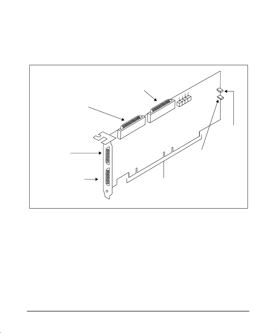
Figure 1-1 below is a drawing (not to scale) of the A6829A adapter.
Figure 1-1 The A6829A PCI Dual Channel Ultra160 SCSI Host Bus Adapter
J6
Channel A
J4
Channel B
68-pin internal
High Density (HD)
SCSI connector
(not supported
on HP-UX
systems)
68-pin internal
High Density (HD)
SCSI connector
(not supported
on HP-UX
systems)
J3
Channel B
68-pin external
Very High Density
Cable Interconnect
(VHDCI) SCSI
connector
J2
Channel A
68-pin external
Very High Density
Cable Interconnect
(VHDCI) SCSI
connector
A_TERM
Channel A
termination
pin set/jumper
B_TERM
Channel B
termination
pin set/jumper
J1T
PCI bus
edge connector
Chapter 14
Page 21

HP A6829A Adapter Overview
Features
The A6829A adapter and its driver conform to the ANSI T10 SCSI
Parallel Interace-3 (SPI-3) standard.
The A6829A adapter has the following features:
• PCI interface
— Full 64-bit (66 MHz) Direct Memory Access (DMA) bus master.
— Zero wait-state bus master data bursts.
— PCI Universal 3.3 V/5 V bus support.
— Compliance with PCI Local Bus Specification, Revision 2.2.
• SCSI interface
— Two separate SCSI channels.
— 16-bit (Wide) Single Ended (SE)/Low Voltage Differential (LVD).
Features
— Enabling/disabling of on-board termination, with hardware
override (using jumpers).
— 68-pin Very High Density Cable Interconnect (VHDCI)
connector for each of the two external channels.
— 68-pin High Density connector for each of the two internal
channels (not supported on HP-UX systems).
— Maximum data transfer rate of 160 MBytes/s per channel, with a
maximum cable length of 12 meters (with multiple SCSI devices)
and a maximum 15 SCSI devices per channel (not including the
A6829A adapter).
— Fast, Ultra, Ultra2, and Ultra160 data transfer capability.
— SCSI termination power (TERMPWR) source with auto-resetting
circuit breaker.
— Flash EEPROM configured with HP part number (allows easy
identification through the ioscan command).
• HBA characteristics
— PCI4X adapter (66MHz, 64-bit data transfers).
Chapter 1 5
Page 22

HP A6829A Adapter Overview
Features
— PCI board dimensions: approximately 8.95 inches x 4.25 inches.
— Universal 64-bit PCI card edge connector.
— Four SCSI connectors:
— Two external 68-pin Very High Density Cable Interconnect
(VHDCI)—J2 and J3, one for each channel.
— Two internal 68-pin High Density (HD)—J4 and J6, one for
each channel. Note that the internal HD connectors are not
supported on HP-UX systems.
— ISA/EISA bracket.
Chapter 16
Page 23

2 Installing the A6829A Adapter
This chapter contains the following sections that describe how to install
the A6829A adapter:
• “Overview of Installation Steps” on page 11.
Chapter 2 9
Page 24

Installing the A6829A Adapter
• “Performance Tuning” on page 13.
• “Preparing for Installation” on page 14.
• “Installing the A6829A Adapter” on page 15.
• “Connecting External SCSI Peripherals” on page 21.
• “Specifying SCSI Parameters” on page 23.
• “Installing the SCSI Driver” on page 53.
• “Configuring LUN 0” on page 55.
• “Adding Multi-Initiator Support” on page 56.
• “Verifying Installation” on page 58.
• “Using the EFI Flash Utility” on page 61.
NOTE This manual provides installation instructions and technical information
for qualified personnel who maintain or service HP-UX systems.
Installing the adapter requires proficiency in both hardware
configuration and software administration.
Chapter 210
Page 25

Installing the A6829A Adapter
Overview of Installation Steps
Overview of Installation Steps
Here is a high-level view of the steps for installing the A6829A HBA:
Step 1. Review the recommendations for performance (see “Performance
Tuning” on page 13).
Step 2. Ensure that you have all the materials you will need (see “Preparing for
Installation” on page 14).
Step 3. Determine what you need to do (if anything) to configure auto
termination for the A6829A adapter (see “Auto Termination” on page 39).
Change the jumper position (see “Using the Jumper for Controlling Auto
Termination” on page 40), if needed, and then go to step 4.
If you do not need to change the position of the jumpers, go to step 4.
Step 4. Install the adapter (see “Installing the A6829A Adapter” on page 15).
Step 5. Attach any external SCSI devices you want to connect to the adapter (see
“Connecting External SCSI Peripherals” on page 21).
Step 6. If necessary, set any of the following SCSI parameters:
• SCSI ID (see “SCSI IDs” on page 27).
• Maximum data transfer rate (see “Maximum Data Transfer Rate” on
page 29).
• Auto termination (see “Auto Termination” on page 39).
• Bus width (see “Bus Width” on page 42).
Before setting the SCSI ID, Maximum data transfer rate, and Bus width
parameters through Boot Control Handler (BCH) menus, ensure that the
HP-UX system supports setting of these parameters in the BCH menus
(see Table 2-2 on page 24).
Step 7. Install the c8xx SCSI driver from the latest HP-UX bundle or HP IT
Resource Center (ITRC) at http://itrc.hp.com.
See “Installing the SCSI Driver” on page 53.
Step 8. If you will be using a disk array in a multi-host environment, be sure you
have a LUN 0 configured (see “Configuring LUN 0” on page 55).
Chapter 2 11
Page 26

Installing the A6829A Adapter
Overview of Installation Steps
Step 9. Verify the installation (see “Verifying Installation” on page 58).
Chapter 212
Page 27

Installing the A6829A Adapter
Performance Tuning
Performance Tuning
To get the best performance from the A6829A adapter, we recommend
the following things:
• Increase the number specified for the scsi_max_qdepth kernel
tunable parameter:
— HP-UX 11.0: scsi_max_qdepth is a static tunable that you can
change in SAM (“Kernel Configuration” screen → “Configurable
Parameters” screen). Note that because this is a static tunable,
you will need to reboot the system after changing its value.
— HP-UX 11i: scsi_max_qdepth is a dynamic tunable, so no
system reboot is needed to change the parameter’s value. See
“SCSI Queue Depth Management” in the HP-UX 11i Release
Notes for more information about this tunable.
If you see “queue full” messages in the /var/adm/syslog.log file,
you can avoid those messages by reducing the value for
scsi_max_qdepth.
• Install the A6829A adapter in a PCI4X slot in the HP-UX system.
• Do not put any Single Ended (SE) SCSI devices on the same SCSI
bus as Low Voltage Differential (LVD) SCSI devices. Doing this
changes the entire bus to SE, which limits the bus to Ultra SCSI (40
MB/s).
• When you are assigning SCSI IDs to the SCSI devices on the bus,
consider giving those devices the higher priorities on the bus (SCSI
ID 7 is usually assigned to the HBA). See “SCSI IDs” on page 27 for
more information.
• Ensure to set the adapter’s maximum data transfer rate to the
correct rate (see “Maximum Data Transfer Rate” on page 29 for more
information).
• Ensure to have the correct SCSI hardware configuration. Domain
Validation can detect some configuration problems (see “Domain
Validation” on page 100).
Chapter 2 13
Page 28

Installing the A6829A Adapter
Preparing for Installation
Preparing for Installation
Installing the A6829A adapter requires disassembly of some system
components. Before beginning the installation, see the HP-UX system’s
manual for detailed instructions about installing host bus adapters in
the PCI slots.
To install the HBA, you need the following:
✓ One HP A6829A SCSI HBA.
✓ One grounding (ESD) kit (shipped with the A6829A).
✓ Any other tools needed for installing components in the HP-UX
system (for example, screwdrivers); see the system’s documentation.
NOTE The maximum number of SCSI HBAs you can install in any HP-UX
system is equal to the maximum number of corresponding card slots in
the system. For example, if a system has four PCI card slots, you can
install four SCSI PCI HBAs in that system, assuming that all the PCI
card slots are empty.
Check the latest SCSI support matrix for systems that support the
A6829A adapter. The support matrix is available at http://docs.hp.com
under the Networking and Communications section.
Chapter 214
Page 29

Installing the A6829A Adapter
Installing the A6829A Adapter
Installing the A6829A Adapter
This section contains information about installing the A6829A HBA in
an HP-UX system (including Online Addition and Replacement [OLAR]).
WARNING The installation procedures in this section require opening the
computer cabinet, which might expose you to high-energy
(high-amperage) circuits and sharp edges in the equipment
chassis. Be sure to remove all rings, watches, and other jewelry
before opening the cabinet.
CAUTION The A6829A adapter contains electronic components that can easily be
damaged by small amount of static electricity. To avoid damage, follow
these guidelines:
• Store the adapter in its antistatic plastic bag until you are ready to
install it.
• Work in a static-free area, if possible.
• Handle the adapter by the edges only. Do not touch electronic
components or electrical traces.
• If you must lay the adapter down, place it on a non-conductive mat or
surface.
• Use the ESD kit that is provided with the adapter. Follow the
instructions included with the kit.
• Use a suitable ground—any exposed metal surface on the system
chassis.
Before beginning installation, and without removing the adapter from its
antistatic bag, inspect the adapter for any signs of obvious damage, such
as chipped or loose components. Contact Hewlett-Packard if the adapter
is damaged.
Install the A6829A in your HP-UX system according to the
documentation for the system.
Chapter 2 15
Page 30

Installing the A6829A Adapter
Installing the A6829A Adapter
NOTE As stated earlier, although the A6829A is supported on only 64-bit
HP-UX 11.0 and 11i, you can install the adapter in either a 32-bit or
64-bit PCI slot. Also, we recommend using a PCI4X slot, to get
maximum performance. However, you can install the adapter in a
PCI2X, PCI1X, or shared PCI slot, if necessary.
When you have finished installing the A6829A, go to the next section
(“Connecting External SCSI Peripherals” on page 21).
Online Addition and Replacement—HP-UX 11i Only
Online Addition and Replacement (OLAR) is the ability of a PCI
host bus adapter to be replaced in or added to an HP-UX system
designed to support this feature, without the need for completely
shutting down and then rebooting the system or adversely affecting
other system components. The system hardware uses the per-slot power
control combined with OS support to enable this feature.
Check the latest SCSI support matrix that contains information on the
HP-UX systems that support OLAR of the A6829A adapter. The support
matrix is available at http://docs.hp.com under the Networking and
Communications section.
IMPORTANT Certain “classes” of hardware are not intended for access by users. At
this time, this includes superdome systems. HP recommends that these
systems be opened by only a qualified HP engineer. Failure to observe
this requirement can invalidate any support agreement or warranty to
which the owner might otherwise be entitled.
You can add or replace an OLAR-compatible adapter in either of these
ways:
• Using the SAM utility.
• Issuing command-line commands, through rad, that refer to the
c8xx OLAR script (/usr/sbin/olard.d/c8xx).
Chapter 216
Page 31

HP recommends that you use SAM instead of the rad command to
perform OLAR procedures. This is because for the most part, SAM
prevents you from performing OLAR procedures that would adversely
affect other areas of the system. This is not true when you use the rad
command.
For detailed information about using either of these two procedures, see
Configuring HP-UX For Peripherals. You can order that document from
Hewlett-Packard, or you can view, download, and print it from
http://www.docs.hp.com.
Table 2-1 below explains some important OLAR-related terms.
Table 2-1 Important OLAR Terms
Term Meaning
OLAR All aspects of the OLAR feature,
Power Domain A grouping of one or more
Installing the A6829A Adapter
Installing the A6829A Adapter
including Online Addition (OLA)
and Online Replacement (OLR).
interface adapter slots that are
powered on or off as a unit.
(Note: Currently, multi-slot
power domains are not
supported.)
target adapter / target adapter
slot
affected adapter / affected
adapter slot
IMPORTANT In many cases, other interface adapters and slots within the system are
dependent on the target adapter. For example, if the target adapter is a
multiple-channel adapter, suspending or deleting drivers for the target
adapter slot also suspends individual drivers for the multiple hardware
paths on that adapter.
Chapter 2 17
The interfaceadapter that will be
added or replaced using OLAR,
and the adapter slot it is in.
Interface adapters and the
adapter slots they are in, and
which are in the same power
domain as the target slot.
Page 32

Installing the A6829A Adapter
Installing the A6829A Adapter
During an adapter replacement operation, SAM performs a Critical
Resource Analysis (CRA), which checks all channels on the target
adapter for critical resources that will be temporarily unavailable while
the adapter is shut down.
Planning and Preparation
As mentioned earlier, for the most part, SAM prevents you from
performing OLAR procedures that would adversly affect other areas of
the HP-UX system. See Configuring HP-UX For Peripherals for detailed
information.
Critical Resources
Replacing an adapter that is still operating can have adverse
consequences. As power to the slot must be off when the old adapter is
removed and the new adapter is inserted, you must consider the effects
of shutting down the adapter’s functions.
This is particularly important if no online failover or backup adapter to
pick up those functions is installed. For example:
• Which mass storage devices will be temporarily disconnected when
the adapter is shut down?
• Will a critical networking connection be lost?
A critical resource is one that would cause a system crash or prevent the
operation from completing successfully if the resources were temporarily
suspended or disconnected. For example, if the SCSI adapter to be
replaced connects to the unmirrored root disk or swap space, the system
will crash when the adapter is shut down.
During an OLAR procedure, it is essential to check the targeted adapter
for critical resources, as well as the effects of existing disk mirrors and
other situations where an adapter’s functions can be taken over by
another adapter that will not be affected.
As mentioned earlier, SAM performs a thorough CRA automatically, and
presents options based on its findings. If you determine that critical
resources will be affected by the procedure, you could replace the adapter
when the system is offline. On the other hand, if you are required to take
an action immediately, you can use the rad command to try an online
addition of a backup adapter and deletion of the target adapter.
Chapter 218
Page 33

Installing the A6829A Adapter
Installing the A6829A Adapter
Adapter Compatibility
This section explains adapter compatibility considerations for
performing OLA and OLR.
Online Addition (OLA) You can add multiple adapters at the same
time. While adding an adapter online, the first issue you must resolve is
whether the new adapter is compatible with the system. Each
OLAR-capable PCI slot provides a set amount of power. The replacement
adapter cannot require more than the available power.
The adapter must also operate at the slot’s bus frequency. A PCI adapter
must run at any frequency lower than its maximum capability, but an
adapter that could operate at only 33 MHz would not work on a bus
running at 66 MHz. The SCSI A6829A HBA operates at 66MHz. The rad
command provides information on the bus frequency and power available
at a slot, as well as other slot-related data.
If your system has one or more slots that support OLAR, and you want to
use OLA to install the A6829A in one of those slots, install the adapter in
your HP-UX system according to the procedure described in the
“Managing PCI Cards with OLAR” chapter of the Configuring HP-UX
Peripherals manual.
After you add a new A6829A adapter, SAM tries to locate the SCSI c8xx
driver. If SAM is unable to locate the driver, you cannot use the new
adapter until you install the driver (remember that driver installation
requires a system reboot). If SAM locates the driver, it determines
whether the new adapter is functional. If the adapter is not functional,
SAM displays an error message.
Online Replacement (OLR) While replacing an interface adapter
online, the replacement adapter must be identical to the adapter being
replaced, or at least be able to operate using the same driver as the
replaced adapter. This is referred to as like-for-like replacement and
should be adhered to, because using a similar but not identical adapter
can cause unpredictable results.
For example, a newer version of the target adapter that is identical to the
older adapter in terms of hardware might contain an updated firmware
version that could potentially conflict with the current driver. In
addition, the old adapter and new adapter must have the same PCI
identifiers (subsystem ID and device ID).
Chapter 2 19
Page 34

Installing the A6829A Adapter
Installing the A6829A Adapter
The PCI specification allows a single physical adapter to contain more
than one channel. A single channel SCSI adapter cannot be replaced by a
dual channel adapter, even if the additional channel(s) on the adapter
are identical to the original SCSI adapter.
When the replacement adapter is added to the system, the appropriate
driver for that adapter must be configured in the kernel before beginning
the replacement operation. SAM ensures the correct driver is present.
(In most cases, the replacement adapter will be of the same type as an
adapter already in the system, and this requirement will be
automatically met.) Keep the following things in mind:
• If the necessary driver is not present and the driver is a dynamically
loadable kernel module (DLKM), you can load it manually. See the
section “Dynamically Loadable Kernel Modules” in Configuring
HP-UX For Peripherals for more information.
• If the driver is static and not configured in the kernel, then the
adapter cannot be added online. The adapter could be physically
inserted online, but no driver will claim it. Note that the SCSI c8xx
driver is a static driver.
If you have any question about the driver’s presence, or if you are not
certain that the replacement adapter is identical to the existing adapter,
you can use the ioscan command together with the rad command to
investigate.
SAM does not allow the A6829A adapter to be suspended in either of the
following situations:
• If the adapter is being used (for example, if a file system is mounted).
• If the CRA shows that a critical resource (for example, swap space or
the root file system) depends on the adapter.
After you replace an A6829A adapter online, SAM checks the
replacement adapter to make sure it is permitted, according to the
like-for-like rules. If the adapter is permitted, SAM automatically
activates it. If it is not permitted, SAM displays an error message.
Chapter 220
Page 35

Installing the A6829A Adapter
Connecting External SCSI Peripherals
Connecting External SCSI Peripherals
The A6829A adapter is capable of communicating with Low Voltage
Differential (LVD) or Single Ended (SE) SCSI devices. LVD allows up to
12m cable lengths with multiple SCSI devices, or 25m point-to-point
connections.
IMPORTANT As stated earlier in this chapter, do not mix LVD SCSI devices with SE
SCSI devices on the bus. If you do so, the entire SCSI bus will change to
SE. This will limit the bus performance to Ultra SCSI (40 MB/s).
Make all external SCSI bus connections to the A6829A adapter with
shielded, 68-pin LVD cables. The connectors on the cable are always
keyed to ensure proper mating.
NOTE No cables or external terminators are shipped with the A6829A adapter.
Cables usually are shipped with the external SCSI devices, and you can
get external terminators for the A6829A by ordering SCSI LVD/SE
terminator (HP product number C2370A).
Chapter 2 21
Page 36

Installing the A6829A Adapter
Connecting External SCSI Peripherals
Figure 2-1 below is a drawing (not to scale) of a typical SCSI shielded
68-pin LVD cable.
Figure 2-1 SCSI Cable for External Connections
Shielded external High Density 68-pin SCSI LVD cable
68-pin VHDCI
(connect to adapter)
68-pin HD
(connect to external
SCSI device)
To connect external SCSI devices to the A6829A adapter, perform the
following steps:
Step 1. Plug the 68-pin VHDCI connector on one end of a shielded external high
density SCSI cable into the adapter’s external connector (J2 or J3).
Step 2. Plug the 68-pin HD connector on the other end of the cable into the SCSI
connector on the external SCSI device.
Step 3. If you need to connect more than one external SCSI device to the adapter,
daisy chain them together with shielded external SCSI cables.
If auto termination is disabled and you want to terminate an external
connector on the HBA, use SCSI LVD/SE terminator (HP product
number C2370A). For more information on auto termination, see “Auto
Termination” on page 39.
When you have finished connecting the external devices, go to the
section, “Specifying SCSI Parameters” on page 23.
Chapter 222
Page 37

Installing the A6829A Adapter
Specifying SCSI Parameters
Specifying SCSI Parameters
To ensure proper operation of the A6829A adapter, the following SCSI
parameters that apply to the entire adapter must be configured correctly:
• SCSI ID (SCSI initiator ID)—see “SCSI IDs” on page 27.
• Maximum data transfer rate (SCSI rate)—see “Maximum Data
Transfer Rate” on page 29.
• Auto termination state—see “Auto Termination” on page 39.
• Bus width—see “Bus Width” on page 42.
NOTE For some of these parameters, you can set the value through commands
in the Boot Console Handler (BCH) menus (on some HP-UX systems);
see Table 2-2 on page 24.
The BCH menus are displayed after the system has booted and before
the OS is running.
If the adapter is new, the SCSI driver uses a default setting suggested by
the system’s firmware, unless you specify a setting through the BCH
menus (if possible). This also happens if the slot in which you install the
adapter has no prior setting for a particular SCSI parameter
If the adapter is new and the slot does have a prior setting, the driver
uses that setting unless you change it through the BCH menus (if
possible).
If the adapter has been used in another slot or in a different system, you
must set the SCSI parameters for the adapter back to their default
values. This is because previously set values for the adapter cannot be
migrated to the new slot or system. See “Setting SCSI Parameters to
Default Values” on page 52 for the steps to follow.
Table 2-2 below is a summary of the supported HP-UX systems and the
SCSI parameters you can set on each one. This table assumes that you
have correct version of PDC on the HP-UX system. To know about the
Chapter 2 23
Page 38

Installing the A6829A Adapter
Specifying SCSI Parameters
correct PDC version information, see the latest SCSI support matrix
available at http://docs.hp.com under the Networking and
Communications section.
Table 2-2 Ability to Set SCSI Parameters on HP-UX Systems
Method for Setting Parameter
HP-UX
System
a400 and
a500
servers
l-class
servers
n-class
servers
SCSI
Parameter
SCSI ID ✓✓
Maximum
data
transfer rate
Auto term
state
Bus width ✓
SCSI ID ✓✓
Maximum
data
transfer rate
Auto term
state
Bus width ✓
SCSI ID ✓✓
Maximum
data
transfer rate
Firmware
Suggested
Default
✓✓
✓✓
✓✓
BCH
Commands
Jumper
(for the
Single
Channel)
✓
✓
Auto term
state
Bus width ✓
✓
Chapter 224
Page 39

Installing the A6829A Adapter
Specifying SCSI Parameters
Table 2-2 Ability to Set SCSI Parameters on HP-UX Systems (Continued)
Method for Setting Parameter
HP-UX
System
hp server
rp24
xx
hp server
rp54
xx
hp server
rp74
xx
SCSI
Parameter
Firmware
Suggested
Default
BCH
Commands
SCSI ID ✓✓
Maximum
✓✓
data
transfer rate
Auto term
state
Bus width ✓
SCSI ID ✓✓
Maximum
data
✓✓
transfer rate
Auto term
state
Bus width ✓
SCSI ID ✓✓
Maximum
data
✓✓
transfer rate
Jumper
(for the
Single
Channel)
✓
✓
Auto term
1
state
✓
Bus width ✓✓
Chapter 2 25
Page 40

Installing the A6829A Adapter
Specifying SCSI Parameters
Table 2-2 Ability to Set SCSI Parameters on HP-UX Systems (Continued)
Method for Setting Parameter
HP-UX
System
hp server
rp8400
hp superd
ome
servers
SCSI
Parameter
Firmware
Suggested
Default
BCH
Commands
SCSI ID ✓✓
Maximum
✓✓
data
transfer rate
Auto term
1
state
Bus width ✓✓
SCSI ID ✓✓
Maximum
data
✓✓
transfer rate
Auto term
1
state
Bus width ✓✓
Jumper
(for the
Single
Channel)
✓
✓
1
See “Summary of Auto Termination Configurations” on page 39 for
information on systems where you can use the jumper to control auto
termination.
Information on configuring each of the SCSI parameters is given in the
later sections.
Chapter 226
Page 41

Installing the A6829A Adapter
Specifying SCSI Parameters
SCSI IDs
You must assign a separate SCSI ID (0 through 15 for a 16-bit SCSI bus)
to the SCSI host bus adapter (HBA) and each SCSI device. The priority
of the device on the SCSI bus is determined by the SCSI ID of the device.
The order of SCSI ID priorities (from highest to lowest) is 7, 6, 5, 4, 3, 2,
1, 0, 15, 14, 13, 12, 11, 10, 9, and 8. A device with SCSI ID 7 has the
highest priority, and one with SCSI ID 8 has the lowest.
When you are assigning SCSI IDs, HP recommends you to give the SCSI
HBA higher priority than the other SCSI devices on the bus. SCSI ID 7 is
the preset SCSI ID for the A6829A SCSI HBA, thereby giving it the
highest priority on the SCSI bus. Set each of the other SCSI devices on
the bus to one of the remaining SCSI IDs.
In a multi-initiator (High Availability [HA]) configuration, multiple SCSI
HBAs are connected to the same SCSI bus. For such configuration, the
SCSI HBA that carries most of the traffic must be assigned a SCSI ID of
7 (highest priority). Later, you must change the SCSI ID of each of the
remaining SCSI HBAs on the bus from the preset setting (7) to the next
highest priority remaining SCSI IDs (for example, 6, 5, 4, and so on).
If you plan to boot your system from a hard disk drive on the SCSI bus,
you must assign that drive the next highest priority unassigned SCSI ID.
If there is only one SCSI HBA (SCSI ID = 7), the hard disk drive will be
assigned a SCSI ID of 6. If there are multiple SCSI HBAs, the hard disk
drive will be assigned the next highest priority SCSI ID available after
all of the SCSI HBAs have been assigned higher priority SCSI IDs.
Setting SCSI IDs
To set the SCSI ID of the A6829A HBA, see “Setting and Confirming
SCSI Parameters” on page 90.
The peripheral device SCSI IDs are usually set with jumpers or a switch
on the peripheral. Refer to the peripheral manufacturer’s instructions to
determine the ID of each device and how to change it.
IMPORTANT You must not have duplicate SCSI IDs on a SCSI bus; the system may
hang or crash if you have duplicate SCSI IDs on the bus.
Chapter 2 27
Page 42

Installing the A6829A Adapter
Specifying SCSI Parameters
Make necessary changes, if any, to the SCSI IDs and record the SCSI IDs
for future reference. To keep a record of the SCSI IDs, you can use
Table 2-3.
Table 2-3 Record of SCSI IDs—A6829A Host Bus Adapter
SCSI ID SCSI Device
15
14
13
12
11
10
9
8
7
6
5
4
3
2
1
0
Chapter 228
Page 43

Installing the A6829A Adapter
Specifying SCSI Parameters
Maximum Data Transfer Rate
The firmware suggested default for the A6829A adapter’s maximum data
transfer rate is the adapter’s maximum speed (160 MB/s). The A6829A
can communicate with all LVD or SE devices that have speeds up to 160
MB/s. This includes the following speeds (synchronous communication
over a Wide bus):
• Fast (20 MB/s)
• Ultra (40 MB/s)
• Ultra2 (80 MB/s)
• Ultra160 (160 MB/s)
The actual transfer rate between the adapter and a SCSI device depends
on the transfer rate that was negotiated between the adapter and the
SCSI device. However, the actual rate will never be greater than the
maximum data transfer rate set for the adapter.
For example, if you set the A6829A’s maximum data transfer rate to
NOLIMIT (which is same as 160 MB/s, in this case), and then connect a
disk drive that has a maximum data transfer rate of Ultra2 (80 MB/s),
the actual transfer rate will be 80 MB/s.
TIP HP recommends that you always set the A6829A’s maximum data
transfer rate to MAX or NOLIMIT (whichever is applicable to the system),
unless you are trying to debug a communication problem between the
adapter and a specific SCSI device. Using MAX or NOLIMIT allows the
adapter’s maximum transfer rate (160 MB/s) to be used.
You can set the A6829A’s maximum data transfer rate in two ways, as
shown in Table 2-2 on page 24.
To set the maximum data transfer rate for A6829A HBA installed in
PA-RISC based system, see “Setting Maximum Data Transfer Rate for
A6829A Host Bus Adapter Installed in PA-RISC Based System” on
page 30.
To set the maximum data transfer rate for A6829A HBA installed in
Itanium-based system, see “Setting Maximum Data Transfer Rate for
A6829A Host Bus Adapter Installed in Itanium‚-Based System” on
page 34.
Chapter 2 29
Page 44

Installing the A6829A Adapter
Specifying SCSI Parameters
Setting Maximum Data Transfer Rate for A6829A Host Bus Adapter Installed in PA-RISC Based System
If the HP A6829A HBA is installed in a supported PA-RISC based
system, use the BCH menu to set the maximum data transfer rate.
The steps for setting the maximum data transfer rate through the BCH
menus (if you do not want to use the default suggested by the system’s
firmware) are mentioned later in this section.
NOTE The following steps and examples are specific to an hp server rp7410.
Menus, command syntax, and responses might be slightly different on
other systems (for example, a maximum data transfer rate of Ultra2 is
not allowed on some HP-UX systems).
For command syntax and valid maximum data transfer rate values, HP
recommends you to use the online help for the scsi command (type
help scsi when you are in the BCH “Service Menu”).
To display and optionally change the A6829A adapter’s maximum data
transfer rate in the BCH menus, perform the following steps:
Step 1. At the “Information Menu,” type fv (to display the PDC version). The
output is as follows:
FIRMWARE INFORMATION
Firmware Version: 15.3
To know about the correct PDC version information, see the latest SCSI
support matrix available at http://docs.hp.com under the Networking and
Communications section.
If you do not have a correct PDC version on your system, contact your HP
support representative.
Step 2. Determine the HBA’s path by performing the following steps:
a. If you are already at the “Main Menu,” type in (for “Information
Menu”), and then go to step b.
If you are not at the “Main Menu,” type main (to return to the “Main
Menu”), type in (for “Information Menu”), and then go to step b.
Chapter 230
Page 45

Installing the A6829A Adapter
Specifying SCSI Parameters
b. At the “Information Menu,” type io (to display I/O interface
information). The output is as follows:
Chapter 2 31
Page 46

Installing the A6829A Adapter
Specifying SCSI Parameters
PCI DEVICE INFORMATION
Path Bus Slot Vendor Device
Description (dec) # # Id Id
----------- ----- --- ------ ------ -----.
.
SCSI bus cntlr 0/0/10/0/0 80 2 0x1000 0x0021
SCSI bus cntlr 0/0/10/0/1 80 2 0x1000 0x0021
.
.
In this example, the HBA’s path is 0/0/10/0/0 and 0/0/10/0/1
(shown in bold in the listing above, for highlighting purposes). Note
that the last (farthest right) digit is the channel number—0 for
channel A, and 1 for channel B.
Step 3. Display (and optionally change) the HBA’s maximum data transfer rate
by performing the following steps:
a. If you are already at the “Main Menu,” type ser (for “Service Menu”);
go to step b.
If you are not at the “Main Menu,” type main (to return to the “Main
Menu”), type ser (for “Service Menu”), and then go to step b.
b. In the “Service Menu,” type the following command:
scsi
path
rate
where
path
is the HBA’s path (from step 1).
Therefore, using the information for channel A of the HBA in the
example in step 1, type the following:
scsi 0/0/10/0/0 rate
This displays the HBA’s maximum data transfer rate. The output is
as follows:
Path (dec) Initiator ID SCSI Rate Auto Term Bus Width
----------------- ------------ --------- --------- --------0/0/10/0/0 7 MAX ON MAX
Chapter 232
Page 47

Installing the A6829A Adapter
Specifying SCSI Parameters
In this example, the HBA’s maximum data transfer rate for channel A
is MAX (shown in bold in the previous listing, for highlighting
purposes). As mentioned earlier, this is the firmware suggested
default setting, and it allows the A6829A’s maximum data rate (160
MB/s) to be used.
If you want to retain the maximum data transfer rate, type main to go
back to the “Main Menu”.
If you want to change the data transfer rate (for example, to
troubleshoot communications between the adapter and an
Ultra-capable SCSI disk), go to step c.
c. If you are still in the “Service Menu,” type the following command:
scsi
path
rate
new_data_rate
where,
to change the HBA’s maximum data transfer rate to (ULTRA, for this
example).
Therefore, using the information for the HBA in step b, type the
following:
scsi 0/0/10/0/0 rate ultra
This changes the HBA’s maximum data transfer rate to ULTRA (40
MB/s).
To ensure that the data transfer rate has changed, you can repeat
step b to display the HBA’s transfer rate.
When your troubleshooting is complete, and you want to change the
adapter’s transfer rate back to MAX, go to step d.
d. If you are still in “Service Menu”, type the following command:
scsi
where,
to change the HBA’s maximum data transfer rate to (MAX, for this
example).
Therefore, using the information for the HBA in step c, type the
following:
scsi 0/0/10/0/0 rate nolimit
path
path
is the HBA’s path and
rate
path
new_data_rate
is the HBA’s path and
new_data_rate
new_data_rate
is what you want
is what you want
This changes the HBA’s maximum data transfer rate back to MAX (160
MB/s).
Chapter 2 33
Page 48

Installing the A6829A Adapter
Specifying SCSI Parameters
To ensure that the data transfer rate has changed, you can repeat
step b to display the HBA’s transfer rate.
When you are satisfied that the maximum data transfer rate is set
correctly, type main to go back to the “Main Menu.”
Chapter 234
Page 49

Installing the A6829A Adapter
Specifying SCSI Parameters
Setting Maximum Data Transfer Rate for A6829A Host Bus Adapter Installed in Itanium-Based System
If the HP A6829A HBA is installed in a supported Itanium-based
system, use the following procedure to set maximum data transfer rate:
Step 1. At the EFI Shell prompt, issue the drivers command as illustrated in
the following example:
Shell> drivers
TD
D YCI
R PFA
V VERSION EGG#D#CDRIVER NAME IMAGE NAME
== ======== ========================================== ===================
14 00000010 B - - 8 18 PCI Bus Driver PciBus
20 01010201 D X X 5 - LSI Logic Ultra160 SCSI Driver PciRomSeg=00000000
21 01010201 D X X 1 - LSI Logic Ultra160 SCSI Driver PciRomSeg=00000000
24 00000200 D X X 3 - LSI Logic Ultra SCSI Driver PciRomSeg=00000000
25 00000200 D X X 1 - LSI Logic Ultra SCSI Driver PciRomSeg=00000000
28 01010201 D X X 1 - LSI Logic Ultra160 SCSI Driver PciRomSeg=00000000
2D 00000105 D X X 1 - HP Tachyon XL2 Fibre Channel Mass S PciRomSeg=00000000
2E 00000105 D X X 2 - HP Tachyon XL2 Fibre Channel Mass S PciRomSeg=00000000
31 00000020 ? - - - - USB Keyboard Driver UsbKeyBoard
32 00000010 ? - - - - UGA Console Driver GraphicsConsole
33 00000000 ? - - - - PCI VGA Mini Port Driver PciVgaMiniPort
34 00000010 ? - - - - VGA Class Driver VgaClassDriver
35 00000010 B - - 1 1 Serial 16550 UART Driver Serial16550
36 00000010 B - - 1 1 Serial Terminal Driver Terminal
37 00000010 D - - 1 - Platform Console Management Driver ConPlatform
38 00000010 D - - 1 - Platform Console Management Driver ConPlatform
39 00000010 B - - 1 1 Console Splitter Driver ConSplitter
Step 2. Find the driver handle designation <drvr_handle>.
For the A6829A HBA, the <drvr_ handle> designation will be in the DRV
column that corresponds to the LSI Logic Ultra160 SCSI Driver
listing in the DRIVER NAME column.
In the preceding example, there are two versions of the LSI Logic
Ultra160 SCSI Driver. The <drvr_handle> designations that
correspond to the two LSI Logic Ultra SCSI Drivers are 20 and 21.
Step 3. Find the controller handle designation, <cntrl_handle>.
At the EFI Shell prompt, issue the drvcfg command as illustrated in
the following example:
Chapter 2 35
Page 50

Installing the A6829A Adapter
Specifying SCSI Parameters
Shell> drvcfg
Configurable Components
Drv[20] Ctrl [1A] Lang [eng]
Drv[20] Ctrl [1B] Lang [eng]
Drv[20] Ctrl [1D] Lang [eng]
Drv[20] Ctrl [1E] Lang [eng]
Drv[20] Ctrl [23] Lang [eng]
Drv[21] Ctrl [22] Lang [eng]
Drv[24] Ctrl [27] Lang [eng]
Drv[24] Ctrl [2B] Lang [eng]
Drv[24] Ctrl [2C] Lang [eng]
Drv[25] Ctrl [26] Lang [eng]
Drv[28] Ctrl [29] Lang [eng]
Drv[2D] Ctrl [30] Lang [eng]
Drv[2E] Ctrl [2A] Lang [eng]
Drv[2E] Ctrl [2F] Lang [eng]
Drv[48] Ctrl [1F] Lang [eng]
From the output of the drvcfg command, look for the line(s) where the
NN in Drv[NN]is same as the <drvr_handle> for the driver(s) you are
using.
The 2nd column, Ctrl [NN], contains the corresponding <cntrl_handle>,
where NN is the controller handle. For example, controller handle 1A, 1B,
1D, 1E, and 23 correspond to driver handle 20, and controller handle 22
corresponds to driver handle 21.
Step 4. Once the driver handle and the controller handle are identified, the SCSI
parameters can be displayed and set for any driver and corresponding
controller (HBA) on the SCSI bus.
Enter the drvcfg -s <drvr_handle> <cntrl_handle> command at
EFI shell prompt. The Global Properties screen containing a list of the
controller (HBA) to which the controller handle corresponds is displayed;
refer to the following example:
LSI Logic Host Bus Adapters
Adapter PCI PCI PCI IRQ NVM LSI Logic
Bus Device Function Control
<53C875 60 01 01> 0 Yes Enabled
Press the [Enter] key. This displays the Adapter Properties screen
containing the controller (HBA) settings; refer to the following example:
Chapter 236
Page 51

Step 5. Use the arrow keys to highlight the Device Properties option, and press
Device Properties
Installing the A6829A Adapter
Specifying SCSI Parameters
Adapter Properties
Adapter PCI PCI PCI
Bus Device Function
53C875 60 01 01
<Device Properties>
Boot Support [Enabled]
SCSI Parity [Yes]
Host SCSI ID [ 5]
SCSI Bus Scan Order [Low to High (0..Max)]
Spinup Delay (Secs) [ 2]
Secondary Cluster Server [Yes]
Termination Control [Auto]
<Restore Defaults>
the [Enter] key. This displays the Device Properties screen; refer to the
following example:
SCSI Device Identifier MB/Sec MT/Sec Data Scan Scan
ID Width ID LUNs > 0
0 - 160 [80] [16] [Yes] [Yes]
1 HP 18.2GST318406LC HP05 160 [80] [16] [Yes] [Yes]
2 HP 18.2GST318406LC HP05 160 [80] [16] [Yes] [Yes]
3 HP 18.2GST318406LC HP05 160 [80] [16] [Yes] [Yes]
4 - 160 [80] [16] [Yes] [Yes]
5 - 160 [80] [16] [Yes] [Yes]
6 53C1010-66 160 [80] [16] [Yes] [Yes]
7 - 160 [80] [16] [Yes] [Yes]
8 - 160 [80] [16] [Yes] [Yes]
9 - 160 [80] [16] [Yes] [Yes]
10 - 160 [80] [16] [Yes] [Yes]
11 HP 18.2GST318406LC HP05 160 [80] [16] [Yes] [Yes]
12 HP 18.2GST318406LC HP05 160 [80] [16] [Yes] [Yes]
13 - 160 [80] [16] [Yes] [Yes]
14 - 160 [80] [16] [Yes] [Yes]
15 HP A6491A HP16 160 [80] [16] [Yes] [Yes]
To change the maximum data transfer rate of the required device, use
the arrow keys to highlight the corresponding option under the MT/Sec
column, and then use the plus (+) or minus (-) keys to change the values.
Chapter 2 37
Page 52

Installing the A6829A Adapter
Specifying SCSI Parameters
NOTE If you set a particular maximum data transfer rate to the SCSI controller
(in this example, 53C1010-66), then the same maximum data transfer
rate is set to all the devices.
This happens because all the devices are connected to the same SCSI
bus, which is controlled by the SCSI controller.
Step 6. After making the necessary changes, press the [ESC] key to exit the
Device Properties screen. This takes you back to the Adapter Properties
screen.
Step 7. Press the [ESC] key to exit the Adapter Properties screen.
If you did not modify any of the SCSI parameters, then the Global
Properties screen appears.
However, if you modified any of the SCSI parameters, then the following
screen appears:
Adapter and/or device property changes have been made.
<Cancel Exit>
<Save changes then exit this menu>
<Discard changes then exit this menu>
Exit the Configuration Utility
Use the arrow keys to highlight your selection from the listed choices,
and then press the [ENTER] key to return to the Global Properties
screen.
Step 8. Press the [ESC] key. This displays the following screen:
Are you sure you want to exit?
<Cancel Exit>
Save changes then exit this menu
Discard changes then exit this menu
<Exit the Configuration Utility>
Use the arrow keys to highlight your selection from the listed choices,
and then press the [ENTER] key to return to the EFI shell prompt.
Chapter 238
Page 53

Installing the A6829A Adapter
Specifying SCSI Parameters
Step 9. At the EFI shell prompt, issue the following command to reboot the
system:
reset
NOTE The system reboot is required for the new setting to take effect.
Chapter 2 39
Page 54

Installing the A6829A Adapter
Specifying SCSI Parameters
Auto Termination
When you configure the A6829A adapter’s auto termination parameter,
you specify the adapter’s role in the SCSI bus termination, because the
adapter might be a point of termination.
For more information on SCSI bus termination, including a tutorial, you
can visit HP IT Resource Center (ITRC) at http://itrc.hp.com.
Controlling Auto Termination
You can control auto termination in the A6829A adapter (see “Using the
Jumper for Controlling Auto Termination” on page 40) depending upon
the HP-UX system in which the adapter is installed (see Table 2-2 on
page 24).
Summary of Auto Termination Configurations
Table 2-4 summarizes the possible A6829A auto termination
configurations.
Table 2-4 Summary of A6829A Auto Termination Configurations
Termination
Applied on
Adapter
Jumper Position
Auto Termination
Feature
Open/ON/ON Enabled Yes
Open/ON/ON Enabled Yes
Open/OFF/ON Disabled
Open/OFF/ON Disabled
Shorted/ON/ON Disabled
Shorted/ON/ON Disabled
Shorted/OFF/ON Disabled
Shorted/OFF/ON Disabled
No
No
No
No
No
No
1
1
1
1
1
1
Chapter 240
Page 55

Installing the A6829A Adapter
Specifying SCSI Parameters
Table 2-4 Summary of A6829A Auto Termination Configurations
Jumper Position
1
An external terminator might be required on the adapter, depending
Auto Termination
Feature
Termination
Applied on
Adapter
on the SCSI bus configuration. If you need an external terminator for
the A6829A, use SCSI LVD/SE terminator (HP product number
C2370A).
Using the Jumper for Controlling Auto Termination
The A6829A adapter has two sets of pins that control enabling and
disabling of the auto termination feature. The pins—labeled A_TERM
and B_TERM—are at the end of the HBA that is opposite to the
bulkhead connectors. Figure 1-1 on page 20 shows where the pin sets are
located on the adapter. A_TERM controls the auto termination feature
for channel A, and B_TERM controls the feature for channel B.
The default setting of each pin set on the A6829A HBA is the open
position (the jumper is on only one pin of its pin set). This is the auto
termination enabled state. In this state, the A6829A automatically
senses whether a cable from a powered SCSI device is attached and
provides the proper termination (depending on whether a powered device
is present).
To disable auto termination on the adapter, change the jumper from the
default open position to the shorted position (the jumper is on both pins
of the pin set). This is the auto termination disabled state.
Chapter 2 41
Page 56

Installing the A6829A Adapter
Specifying SCSI Parameters
The following Figure 2-2 shows the two jumper positions.
Figure 2-2 Auto Termination Jumper Positions
Open
(Auto termination enabled)
Shorted
(Auto termination disabled)
Chapter 242
Page 57

Installing the A6829A Adapter
Specifying SCSI Parameters
Bus Width
The firmware suggested default for the A6829A adapter’s bus width is
MAX (use the adapter’s maximum bus width [16 bits]). However, either of
these rates can be used for the A6829A:
• 8 bits (Narrow)
• 16 bits (Wide)
TIP HP recommends you to always use the A6829A’s maximum bus width
(16 bits), unless you have Narrow (8-bit) devices on the bus and you are
experiencing problems with the connection.
You can set the A6829A’s bus width in one or two ways, depending on the
HP-UX system the adapter is installed in (refer to Table 2-2 on page 24).
To set the bus width for A6829A HBA installed in PA-RISC based
system, see “Setting Bus Width for A6829A Host Bus Adapter Installed
in PA-RISC Based System” on page 43.
To set the bus width for A6829A HBA installed in Itanium-based
system, see “Setting Bus Width for A6829A Host Bus Adapter Installed
in Itanium‚-Based System” on page 47.
Chapter 2 43
Page 58

Installing the A6829A Adapter
Specifying SCSI Parameters
Setting Bus Width for A6829A Host Bus Adapter Installed in PA-RISC Based System
If the HP A6829A HBA is installed in a supported PA-RISC based
system, use the BCH menu to set the bus width.
The steps for setting the bus width through the BCH menus (if you do
not want to use the default suggested by the system’s firmware) are
given below.
NOTE The following steps and examples are specific to HP server rp7410.
Menus, command syntax, and responses might be slightly different on
other systems.
For command syntax and valid bus width values, HP recommends you
to use the online help for the scsi command (type help scsi when you
are in the BCH “Service Menu”).
To display and optionally change the A6829A adapter’s bus width in the
BCH menus, perform the following steps:
Step 1. Check the PDC (system firmware) version by performing the following
steps:
a. If you are already at the “Main Menu,” type in (for “Information
Menu”); go to step b.
If you are not at the “Main Menu,” type main (to return to the “Main
Menu”), type in (for “Information Menu”), and then go to step b.
b. At the “Information Menu,” type fv (to display the PDC version). The
output is as follows:
FIRMWARE INFORMATION
Firmware Version: 15.3
To know about the correct PDC version information, see the latest
SCSI support matrix available at http://docs.hp.com under the
Networking and Communications section.
If you do not have a correct PDC version on your system, contact your
HP support representative.
Chapter 244
Page 59

Installing the A6829A Adapter
Specifying SCSI Parameters
Step 2. Determine the HBA’s path by doing the following:
a. If you are already at the “Main Menu,” type in (for “Information
Menu”); go to step b.
If you are not at the “Main Menu,” type main (to return to the “Main
Menu”), type in (for “Information Menu”), and then go to step b.
b. At the “Information Menu,” type io (to display I/O interface
information). The output is as follows:
PCI DEVICE INFORMATION
Path Bus Slot Vendor Device
Description (dec) # # Id Id
----------- ----- --- ------ ------ -----.
.
SCSI bus cntlr 0/0/10/0/0 80 2 0x1000 0x0021
SCSI bus cntlr 0/0/10/0/1 80 2 0x1000 0x0021
.
.
In this example, the HBA’s path is 0/0/10/0/0 and 0/0/10/0/1
(shown in bold in the listing above, for highlighting purposes). Note
that the last (farthest right) digit is the channel number—0 for
channel A and 1 for channel B.
Step 3. Display (and optionally change) the HBA’s bus width by performing the
following steps:
a. If you are already at the “Main Menu,” type ser (for “Service Menu”);
go to step b.
If you are not at the “Main Menu,” type main (to return to the “Main
Menu”), type ser (for “Service Menu”), and then go to step b.
b. In the “Service Menu,” type the following command:
scsi
path
width
where,
path
is the HBA’s path (from step 1).
Therefore, using the information for channel A of the HBA in the
example in step 1, type the following:
scsi 0/0/10/0/0 width
This displays the HBA’s bus width. The output is as follows:
Chapter 2 45
Page 60

Installing the A6829A Adapter
Specifying SCSI Parameters
Path (dec) Initiator ID SCSI Rate Auto Term Bus Width
----------------- ------------ --------- --------- --------0/0/10/0/0 7 MAX ON MAX
In this example, the HBA’s bus width is MAX (shown in bold in the
previous listing). As mentioned earlier, this is the firmware suggested
default setting.
If you want to retain the bus width, type main to go back to the “Main
Menu”; you are finished with the bus width for channel A.
If you want to change the bus width (for example, because you have
Narrow devices on the SCSI bus and you are having problems with
the connection), go to step c.
c. If you are still in the “Service Menu,” type the following command:
scsi
path
width
new_bus_width
where,
path
is the HBA’s path and
new_bus_width
is what you want
to set the HBA’s bus width to (8, for this example).
Therefore, using the information for the HBA in step b, type the
following:
scsi 6/0/4/0/0 width 8
This changes the HBA’s bus width to 8.
To ensure that the bus width has changed, you can repeat step b to
display the HBA’s bus width.
When you have fixed the problem with the connection, and you want
to change the adapter’s bus width back to MAX, go to step d.
d. If you are still in “Service Menu”, type the following command:
scsi
path
where,
width
path
new_bus_width
is the HBA’s path and
new_bus_width
is what you want
to change the HBA’s bus width to (MAX, for this example).
Therefore, using the information for the HBA in step c above, type the
following:
scsi 0/0/10/0/0 width 0
This changes the HBA’s bus width back to MAX.
To ensure that the bus width has changed, you can repeat step b to
display the HBA’s bus width.
Chapter 246
Page 61

Installing the A6829A Adapter
Specifying SCSI Parameters
When you are satisfied that the bus width is set correctly, type main to
get back to the “Main Menu.”
Chapter 2 47
Page 62

Installing the A6829A Adapter
Specifying SCSI Parameters
Setting Bus Width for A6829A Host Bus Adapter Installed in Itanium-Based System
If the HP A6829A HBA is installed in a supported Itanium-based
system, use the following procedure to set the bus width:
Step 1. At the EFI Shell prompt, issue the drivers command as illustrated in
the following example:
Shell> drivers
TD
D YCI
R PFA
V VERSION EGG#D#CDRIVER NAME IMAGE NAME
== ======== ========================================== ===================
14 00000010 B - - 8 18 PCI Bus Driver PciBus
20 01010201 D X X 5 - LSI Logic Ultra160 SCSI Driver PciRomSeg=00000000
21 01010201 D X X 1 - LSI Logic Ultra160 SCSI Driver PciRomSeg=00000000
24 00000200 D X X 3 - LSI Logic Ultra SCSI Driver PciRomSeg=00000000
25 00000200 D X X 1 - LSI Logic Ultra SCSI Driver PciRomSeg=00000000
28 01010201 D X X 1 - LSI Logic Ultra160 SCSI Driver PciRomSeg=00000000
2D 00000105 D X X 1 - HP Tachyon XL2 Fibre Channel Mass S PciRomSeg=00000000
2E 00000105 D X X 2 - HP Tachyon XL2 Fibre Channel Mass S PciRomSeg=00000000
31 00000020 ? - - - - USB Keyboard Driver UsbKeyBoard
32 00000010 ? - - - - UGA Console Driver GraphicsConsole
33 00000000 ? - - - - PCI VGA Mini Port Driver PciVgaMiniPort
34 00000010 ? - - - - VGA Class Driver VgaClassDriver
35 00000010 B - - 1 1 Serial 16550 UART Driver Serial16550
36 00000010 B - - 1 1 Serial Terminal Driver Terminal
37 00000010 D - - 1 - Platform Console Management Driver ConPlatform
38 00000010 D - - 1 - Platform Console Management Driver ConPlatform
39 00000010 B - - 1 1 Console Splitter Driver ConSplitter
Step 2. Find the driver handle designation <drvr_handle>.
For the A6829A HBA, the <drvr_ handle> designation will be in the DRV
column that corresponds to the LSI Logic Ultra160 SCSI Driver
listing in the DRIVER NAME column.
In the preceding example, there are two versions of the LSI Logic
Ultra160 SCSI Driver. The <drvr_handle> designations that
correspond to the two LSI Logic Ultra SCSI Drivers are 20 and 21.
Step 3. Find the controller handle designation, <cntrl_handle>.
At the EFI Shell prompt, issue the drvcfg command as illustrated in
the following example:
Chapter 248
Page 63

Installing the A6829A Adapter
Specifying SCSI Parameters
Shell> drvcfg
Configurable Components
Drv[20] Ctrl [1A] Lang [eng]
Drv[20] Ctrl [1B] Lang [eng]
Drv[20] Ctrl [1D] Lang [eng]
Drv[20] Ctrl [1E] Lang [eng]
Drv[20] Ctrl [23] Lang [eng]
Drv[21] Ctrl [22] Lang [eng]
Drv[24] Ctrl [27] Lang [eng]
Drv[24] Ctrl [2B] Lang [eng]
Drv[24] Ctrl [2C] Lang [eng]
Drv[25] Ctrl [26] Lang [eng]
Drv[28] Ctrl [29] Lang [eng]
Drv[2D] Ctrl [30] Lang [eng]
Drv[2E] Ctrl [2A] Lang [eng]
Drv[2E] Ctrl [2F] Lang [eng]
Drv[48] Ctrl [1F] Lang [eng]
From the output of the drvcfg command, look for the line(s) where the
NN in Drv[NN]is same as the <drvr_handle> for the driver(s) you are
using.
The 2nd column, Ctrl [NN], contains the corresponding <cntrl_handle>,
where NN is the controller handle. For example, controller handle 1A, 1B,
1D, 1E, and 23 correspond to driver handle 20, and controller handle 22
corresponds to driver handle 21.
Step 4. Once the driver handle and the controller handle are identified, the SCSI
parameters can be displayed and set for any driver and corresponding
controller (HBA) on the SCSI bus.
Enter the drvcfg -s <drvr_handle> <cntrl_handle> command at
EFI shell prompt. The Global Properties screen containing a list of the
controller (HBA) to which the controller handle corresponds is displayed;
refer to the following example:
LSI Logic Host Bus Adapters
Adapter PCI PCI PCI IRQ NVM LSI Logic
Bus Device Function Control
<53C875 60 01 01> 0 Yes Enabled
Press the [Enter] key. This displays the Adapter Properties screen
containing the controller (HBA) settings; refer to the following example:
Chapter 2 49
Page 64

Installing the A6829A Adapter
Specifying SCSI Parameters
Adapter Properties
Adapter PCI PCI PCI
53C875 60 01 01
Step 5. Use the arrow keys to highlight the Device Properties option, and press
the [Enter] key. This displays the Device Properties screen; refer to the
following example:
Device Properties
Bus Device Function
<Device Properties>
Boot Support [Enabled]
SCSI Parity [Yes]
Host SCSI ID [ 5]
SCSI Bus Scan Order [Low to High (0..Max)]
Spinup Delay (Secs) [ 2]
Secondary Cluster Server [Yes]
Termination Control [Auto]
<Restore Defaults>
SCSI Device Identifier MB/Sec MT/Sec Data Scan Scan
ID Width ID LUNs > 0
0 - 160 [80] [16] [Yes] [Yes]
1 HP 18.2GST318406LC HP05 160 [80] [16] [Yes] [Yes]
2 HP 18.2GST318406LC HP05 160 [80] [16] [Yes] [Yes]
3 HP 18.2GST318406LC HP05 160 [80] [16] [Yes] [Yes]
4 - 160 [80] [16] [Yes] [Yes]
5 - 160 [80] [16] [Yes] [Yes]
6 53C1010-66 160 [80] [16] [Yes] [Yes]
7 - 160 [80] [16] [Yes] [Yes]
8 - 160 [80] [16] [Yes] [Yes]
9 - 160 [80] [16] [Yes] [Yes]
10 - 160 [80] [16] [Yes] [Yes]
11 HP 18.2GST318406LC HP05 160 [80] [16] [Yes] [Yes]
12 HP 18.2GST318406LC HP05 160 [80] [16] [Yes] [Yes]
13 - 160 [80] [16] [Yes] [Yes]
14 - 160 [80] [16] [Yes] [Yes]
15 HP A6491A HP16 160 [80] [16] [Yes] [Yes]
To change the bus width of the required device, use the arrow keys to
highlight the corresponding option under the Data Width column, and
then use the plus (+) or minus (-) keys to change the values.
Chapter 250
Page 65

Installing the A6829A Adapter
Specifying SCSI Parameters
NOTE As stated earlier, HP recommends you to always use the A6829A’s
maximum bus width (16 bits), unless you have Narrow (8-bit) devices on
the bus and you are experiencing problems with the connection.
If you decrease the maximum bus width value (16 bits) when the
transfer rate (MT/sec) is set to 80 or 160, the following message is
displayed:
Data Width cannot be set to narrow when MT/Sec is set to 80 or 160.
Press any key to continue.
If you want to decrease the maximum bus width value of a particular
device, first set the transfer rate (MT/sec) to a lower value, and then
decrease the corresponding bus width value.
Step 6. After making the necessary changes, press the [ESC] key to exit the
Device Properties screen. This takes you back to the Adapter Properties
screen.
Step 7. Press the [ESC] key to exit the Adapter Properties screen.
If you did not modify any of the SCSI parameters, then the Global
Properties screen appears.
However, if you modified any of the SCSI parameters, then the following
screen appears:
Adapter and/or device property changes have been made.
<Cancel Exit>
<Save changes then exit this menu>
<Discard changes then exit this menu>
Exit the Configuration Utility
Use the arrow keys to highlight your selection from the listed choices,
and then press the [ENTER] key to return to the Global Properties
screen.
Step 8. Press the [ESC] key. This displays the following screen:
Chapter 2 51
Page 66

Installing the A6829A Adapter
Specifying SCSI Parameters
Are you sure you want to exit?
<Cancel Exit>
Save changes then exit this menu
Discard changes then exit this menu
<Exit the Configuration Utility>
Use the arrow keys to highlight your selection from the listed choices,
and then press the [ENTER] key to return to the EFI shell prompt.
Step 9. At the EFI shell prompt, issue the following command to reboot the
system:
reset
NOTE The system reboot is required for the new setting to take effect.
Chapter 252
Page 67

Installing the A6829A Adapter
Specifying SCSI Parameters
Setting SCSI Parameters to Default Values
You can set the SCSI parameters, except Auto Termination, for the
adapter to their default values through the BCH menus. The steps you
follow depend on the type of HP-UX system in which the adapter is
installed.
hp servers rp7410, rp8400, and superdome
On hp servers rp7410, rp8400, and superdome, set the SCSI parameters
to the default values by performing the following steps:
Step 1. If you are already at the “Main Menu,” type ser (for “Service Menu”); go
to step 2.
If you are not at the “Main Menu,” type main (to return to the “Main
Menu”), type ser (for “Service Menu”), and then go to step 2.
Step 2. In the “Service Menu,” type the following command:
scsi
path
default
where,
the
Step 3. Type main to get back to the “Main Menu.”
All Other Servers
On all servers other than hp servers rp7410, rp8400, and superdome, set
the SCSI parameters to the default values by following the steps for
specifying each SCSI parameter (described earlier in this section).
You will need to know the default value—and how to specify it—for each
SCSI parameter. To know the valid SCSI parameter values, HP
recommends you to use the online help for the scsi command (type
help scsi when you are in the BCH “Service Menu”).
path
is the HBA’s path. This sets all of the SCSI parameters for
path
to their default values.
Chapter 2 53
Page 68

Installing the A6829A Adapter
Installing the SCSI Driver
Installing the SCSI Driver
On most of the supported HP-UX PA-RISC systems, the SCSI c720
driver is used with some of the SCSI interfaces. This driver is
automatically installed as part of the HP-UX 11.0 core OS and the
HP-UX 11i base Operating Environment (OE). Therefore, you do not
have to install it separately.
However, you must separately install the SCSI c8xx driver, which is
used by the A6829A HBA in all the supported HP-UX systems. This
driver is available in the latest HP-UX bundle or at http://itrc.hp.com.
TIP You should keep in mind that, although the installation process installs
the c8xx driver, it does not load the c8xx driver into the HP-UX kernel
unless it detects one or more SCSI Ultra160 devices installed in the
HP-UX system. This is done to prevent the kernel from becoming
unnecessarily large.
Therefore, if Ultra160 devices (for example, a SCSI Ultra160 “add-in”
adapter [like the A6829A] or core I/O card) are already installed in the
HP-UX system, or if you will be installing an Ultra160 add-in adapter
later through OLA, you should install the c8xx driver now. If no SCSI
Ultra160 devices are in the system, and you do not want to install any
Ultra160 add-in adapters later, do not install the c8xx driver at this
time.
NOTE You must install all patches before you install the bundle containing the
c8xx driver.
The following is an overview of the steps you need to perform:
Step 1. Issue the swlist command to see which patches are already installed on
the system. You can get any patches you need to install from the HP IT
Resource Center (ITRC) at http://itrc.hp.com.
If you do not need to install any patches (other than the c8xx bundle), go
to step 3.
Chapter 254
Page 69

Installing the A6829A Adapter
Installing the SCSI Driver
If you need to install one or more patches, go to step 2.
Step 2. Install any necessary patches.
Step 3. Follow the normal procedure to install the appropriate software bundle
for your HP-UX system’s OS or OE.
Step 4. Issue the swlist command to ensure that the necessary patches and the
c8xx driver are present.
Step 5. Check to see if the c8xx driver is loaded in the kernel, by doing one of the
following two things:
• Use SAM, as follows:
1. Select the “Kernel Configuration” icon.
2. Select the “Drivers” icon.
3. In the “Kernel Configuration” screen, check to see if the c8xx
driver is in the kernel.
• Issue the following command:
what /stand/vmunix | grep scsi_c8xx.c
Check to see if the c8xx driver is listed.
If the driver is in the kernel, go to the section, “Configuring LUN 0” on
page 55.
If the driver is not in the kernel, go to step 6
Step 6. Load the c8xx driver into the kernel through SAM:
a. Select the “Kernel Configuration” icon.
b. Select the “Drivers” icon.
c. In the “Kernel Configuration” screen, follow the normal steps for
loading the driver into the kernel (and building a new kernel).
NOTE You need to reboot the system after completing these steps.
Once you have confirmed that the c8xx driver is in the kernel, go to
section, “Configuring LUN 0” on page 55.
Chapter 2 55
Page 70

Installing the A6829A Adapter
Configuring LUN 0
Configuring LUN 0
For a disk array that is in a multi-host environment, the SCSI standard
requires a LUN 0 in certain scenarios:
• If the disk array is connected to the A6829A adapter, and you plan to
boot from that array, the disk array must be configured as LUN 0. Do
not configure the LUN with any LUN security (that is, do not restrict
access).
• If the disk array is connected to an A6829A adapter installed in an
HP-UX system that is running from a separate boot disk, the disk
array must be configured with LUN 0; otherwise, the ioscan
command will not detect all of the LUNs present in the disk array.
Once you have determined that LUN 0—if it is required—is configured
correctly, go to the section, “Verifying Installation” on page 58.
Chapter 256
Page 71

Installing the A6829A Adapter
Adding Multi-Initiator Support
Adding Multi-Initiator Support
In a multi-initiator configuration, multiple SCSI host bus adapters
(HBA) are connected to the same SCSI bus. Multi-initiator is supported
for A6829A HBAs having part number A6829A-60101 or higher.
NOTE Multi-initiator is not supported for HP A6829A SCSI HBA with part
number A6829A-60001.
If you need multi-initiator support for an Itanium-based system, follow
the steps mentioned in the section, “Multi-Initiator Support for
Itanium‚-Based System” on page 57.
If you need multi-initiator support for a PA-RISC based system, follow
the steps mentioned in the section, “Multi-Initiator Support for PA-RISC
Based System” on page 57.
Chapter 2 57
Page 72

Installing the A6829A Adapter
Adding Multi-Initiator Support
Multi-Initiator Support for Itanium-Based System
If you need multi-initiator support for HP A6829A SCSI HBA installed
in an Itanium-based system, perform the following steps:
Step 1. Ensure that the part number of the HBA is A6829A-60101.
Step 2. Install the driver patch, PHKL_28566.
Multi-Initiator Support for PA-RISC Based System
If you need multi-initiator support for HP A6829A SCSI HBA installed
in a PA-RISC based system, perform the following steps:
Step 1. Ensure that the part number of the HBA is A6829A-60101.
Step 2. Install the appropriate driver patch. Refer to Table 2-5 for information
on the patch you need to install on your system.
Table 2-5 Mapping of System Version to Driver Patch
System Version Driver Patch
HP-UX 11.0 PHKL_27555
HP-UX 11i PHKL_27556
Chapter 258
Page 73

Installing the A6829A Adapter
Verifying Installation
Verifying Installation
After installing the adapter and the c8xx driver and attaching the
peripheral devices, verify that all of the components are working by
performing the following steps:
Step 1. To verify that the adapter is correctly installed, issue the following
command:
ioscan -fnk
The applicable lines in the ioscan output can have the following form:
ext_bus 0 0/0/10/0/0 c8xx CLAIMED INTERFACE SCSI C1010 Ultra160 Wide LVD A6829-60101
ext_bus 0 0/0/10/0/1 c8xx CLAIMED INTERFACE SCSI C1010 Ultra160 Wide LVD A6829-60101
The third column shows the hardware path of the PCI device/function
(shown in bold in the above example, for highlighting purposes). The
A6829A supports two PCI devices/functions (one per channel). In
addition, since this is a dual channel HBA, two lines are listed—one for
channel A of the adapter (denoted by a 0 as the last digit in the hardware
path), and one for channel B (denoted by a 1 as the last digit).
Step 2. In the same lines of the ioscan output, verify that the adapter is claimed
by the SCSI c8xx driver, by looking at the fifth column of information
(shown in bold in the example below, for highlighting purposes):
ext_bus 0 0/0/10/0/0 c8xx CLAIMED INTERFACE SCSI C1010 Ultra160 Wide LVD A6829-60101
ext_bus 0 0/0/10/0/1 c8xx CLAIMED INTERFACE SCSI C1010 Ultra160 Wide LVD A6829-60101
If the adapter is not claimed, see “If the A6829A Adapter is Not Claimed”
on page 88.
Step 3. Still in the same lines of the ioscan output, verify that the SCSI driver
and adapter information are displayed (they are shown in bold in the
example below, for highlighting purposes):
ext_bus 0 0/0/10/0/0 c8xx CLAIMED INTERFACE SCSI C1010 Ultra160 Wide LVD A6829-60101
ext_bus 0 0/0/10/0/1 c8xx CLAIMED INTERFACE SCSI C1010 Ultra160 Wide LVD A6829-60101
In this example, the SCSI driver information is c8xx (the name of the
driver), and the adapter information is as follows:
Chapter 2 59
Page 74

Installing the A6829A Adapter
Verifying Installation
• SCSI C1010—The type of HBA (SCSI) and the type of Ultra160
controller (C1010).
• Ultra160—The HBA’s maximum data transfer rate. This can be
Ultra160, Ultra2, Ultra, Fast, or Async. You should keep the
following in mind:
— This is not the actual transfer rate, but the maximum transfer
— This is either the firmware default or the rate set through the
• Wide—The HBA’s bus width. This can be Wide or Narrow.
• LVD—The HBA’s bus type. This can be LVD or Single-Ended. If no
bus type is shown, then the SCSI channel is disabled.
• A6829-60101—The HBA’s HP part number.
Step 4. In addition, in the ioscan output, the ctl lines show the adapter’s SCSI
ID in its hardware path (shown in bold in the example below, for
highlighting purposes):
rate set for the HBA.
BCH menus, unless you attach an SE device, which causes the
entire bus to change to a transfer rate of Ultra (see “Performance
Tuning” on page 13).
ctl 0 0/0/10/0/0.7.0 sctl CLAIMED DEVICE Initiator
/dev/rscsi/c0t7d0
ctl 1 0/0/10/0/1.7.0 sctl CLAIMED DEVICE Initiator
/dev/rscsi/c1t7d0
Step 5. Verify that the devices you attached to the adapter are present in the
ioscan output. For example, a partial list may look like this:
disk 10 0/0/1/0/1.0.0 sdisk CLAIMED DEVICE SEAGATE ST39103LC
/dev/dsk/c1t0d0 /dev/rdsk/c1t0d0
disk 11 0/0/1/0/1.2.0 sdisk CLAIMED DEVICE SEAGATE ST39103LC
/dev/dsk/c1t2d0 /dev/rdsk/c1t2d0
disk 45 0/2/1/0/1.8.0 sdisk CLAIMED DEVICE HP 18.2GST318404LC
/dev/dsk/c9t8d0 /dev/rdsk/c9t8d0
disk 46 0/2/1/0/1.10.0 sdisk CLAIMED DEVICE HP 18.2GST318404LC
/dev/dsk/c9t10d0 /dev/rdsk/c9t10d0
Chapter 260
Page 75

Installing the A6829A Adapter
Verifying Installation
The second line under each disk line shows the disk’s device files
(/dev/... [shown in bold in the example above, for highlighting
purposes]).
TIP When the system boots after installation, the insf command creates the
proper device files for the “ctl” interfaces (which are usually adapters)
and the SCSI devices attached to the A6829A adapter. Sometimes,
though, it does not create all of the needed device files.
One situation when this happens is when you attach SCSI disks to the
adapter after the system boots and the adapter is already installed in the
system.
In the ioscan output, if you see a SCSI device listed without the second
line, that means you are missing that device’s device files. To fix the
problem, issue the insf -e command, which creates all of the device
files.
For more information about the ioscan command, see the ioscan(1M)
man page.
Refer to your system documentation for information about verifying
system operation.
Chapter 2 61
Page 76

Installing the A6829A Adapter
Using the EFI Flash Utility
Using the EFI Flash Utility
If you are installing the A6829A SCSI HBA in an Itanium-based
system, use the Extended Firmware Interface (EFI) flash utility to verify
the firmware version, or to flash and save firmware images onto the
A6829A HBA.
The EFI flash utility is supported on HP A6829A SCSI HBA, which is
based on the 53C1010 LSI Logic SCSI chip.
Features
The features of the EFI flash utility are as follows:
• Supports HBA selection for updating the SCSI parameters.
• Displays the firmware version on an HBA or in a firmware image file.
• Supports a menu driven mode.
• Allows you to flash the EFI option ROM images.
Description
This utility allows you to update the HBA flash memory with the LSI
Logic EFI driver. New versions of these images are released periodically.
Your HBA must have a flash memory to use this utility.
WARNING Do not attempt to use this utility to flash any binaries other than
the EFI option ROM images.
The executable file name of the EFI utility is EFI8XXFL.EFI. This file,
and any firmware image files you need, must be stored on a diskette or
CD-ROM. These files must not be stored on a hard disk, because if the
flash fails, there is no way to recover these files. Moreover, the hard disk
may not be accessible.
Chapter 262
Page 77

Installing the A6829A Adapter
Using the EFI Flash Utility
The EFI utility should be executed from a diskette or CD-ROM. For EFI
based systems without a floppy diskette drive, burning the EFI utility
and other firmware images onto a CD-ROM allows proper execution, but
with reduced functionality. In such a situation, you will not be able to
save an image of the flash memory to the CD-ROM.
Preparation
While booting the EFI enabled systems, the diskette or CD-ROM
containing the EFI utility needs to be in the drive to allow device
mapping. The EFI utility and firmware image files are located in the root
directory or in a subdirectory on the diskette or CD-ROM.
Boot the system to the EFI shell prompt. The floppy diskette drive or
CD-ROM drive should appear in the list of mapped devices as fs0.
In systems with a floppy drive, type fs0 at the EFI shell prompt to
change to this device.
Menu Driven Mode
If the EFI utility and firmware image files are located in the root
directory, enter the efi8xxfl command at the prompt as illustrated
below; otherwise, move to the directory in which these files are located
and continue.
fs0:\> efi8xxfl
The following main window screen appears:
Vendor Device
Choice ID ID Seg Bus Dev Func Flash Part
------- -------- -------- ------- ------ ------ ------- ------------
1 0x1000 0x021 0x00 0x15 0x01 0x00 M29F010B
LSI Logic, Inc. SYMC1010 Ultra160 66Mhz SCSI
2 0x1000 0x021 0x00 0x15 0x01 0x01 M29F010B
LSI Logic, Inc. SYMC1010 Ultra160 66Mhz SCSI
3 0x1000 0x021 0x00 0x3F 0x01 0x00 Am29F010
LSI Logic, Inc. SYMC1010 Ultra160 66Mhz SCSI
4 0x1000 0x021 0x00 0x3F 0x01 0x01 Am29F010
LSI Logic, Inc. SYMC1010 Ultra160 66Mhz SCSI
Chapter 2 63
Page 78

Installing the A6829A Adapter
Using the EFI Flash Utility
5 0x1000 0x021 0x01 0x16 0x01 0x00 Am29F010
LSI Logic, Inc. SYMC1010 Ultra160 66Mhz SCSI
6 - Refresh
Which chip/adapter (0 to quit)?
The main window allows you to choose the SCSI chip corresponding to
the path where you want to perform the selected tasks. Dual channel
cards display two entries (one for each SCSI chip) on this screen.
In the aforementioned example, the system has three HBAs - one each on
the 0x15, 0x3F, and 0x16 buses. The HBA on bus 0x3F is a dual-channel
HBA (func 0x00 and func 0x01) with flash memory part number
Am29F010. Since both the channels of a dual channel board share the
same flash memory, only one of the paths needs to be chosen. If separate
updates are performed through both the paths, the flash memory is not
affected.
NOTE Each update overwrites the existing contents of the flash memory.
The segment value of the HBA corresponding to Choice number 5 is
0x01. This indicates that the HBA resides on PCI segment 1. The other
HBAs reside on PCI segment 0, as the segment value for other HBAs is
0x00.
The SYMC1010 following LSI Logic, Inc. indicates that the HBAs use
the 53C1010 LSI SCSI chip, which is supported by this EFI utility.
If a device does not contain an LSI Logic SCSI chip supported by the EFI
utility, the lines listing the chip numbers do not appear in the display.
The HP A6829A SCSI HBA is based on the LSI Logic 53C1010 SCSI
chip.
At the Which chip/adapter (0 to quit)? prompt, enter the number
under Choice that corresponds to the SCSI chip associated with the
flash memory you want to update. Refer to the following example where
chip 1 is selected:
Which chip/adapter (0 to quit)? 1
The following menu is displayed:
Chapter 264
Page 79

Installing the A6829A Adapter
Using the EFI Flash Utility
LSI Logic Corporation EFI 53C8xx/53C1010 FLASH Utility.
EFI8XXFL-1.00.00.00 (05.05.2003)
Copyright (c) 2003 LSI Logic Corporation. All rights reserved.
********************************************************************
FLASH
a - Identify Flash Image
b - Download New Flash Image
c - Upload Current Flash Image to a File
d - Erase Entire Flash Part
MISC
z - Change Current PCI chip/adapter
q - Quit
Selection:
In the preceding menu, the banner at the top of the option menu displays
the version of the EFI update utility and the release date.
The details on each of the menu choices are as follows:
a Identify Flash Image: Displays the version number of the image in
the flash memory associated with the currently selected chip or the
image contained in the firmware image file.
b Download New Flash Image: Overwrites the flash memory associated
with the currently selected chip with a new firmware image file. This
menu choice prompts you for a file name.
NOTE The EFI utility does not flash an image that exceeds the capacity of the
flash memory on the selected HBA. Instead, a warning message is
displayed.
c Upload Current Flash Image to a File: Saves the image from the
flash memory associated with the currently selected chip to a file. This
menu choice prompts you for a file name.
d Erase Entire Flash Part: Erases the entire flash memory
associated with the currently selected chip. Once the flash memory is
erased, you must download a new Flash image (select option [b]) before
the HBA is able to function in the boot sequence.
When the EFI utility flashes an adapter, the following message is
displayed:
Chapter 2 65
Page 80

Installing the A6829A Adapter
Using the EFI Flash Utility
Updating the adapter at: PCI seg 0x00, bus 0x3F, dev 0x01, func 0x00
Updating VPD of NVM with new image version...........
Begin erase cycle...
Erase complete.
Chapter 266
Page 81

3 Troubleshooting
The A6829A adapter is a single field-replaceable unit (FRU) and does not
contain any field-serviceable parts. Troubleshooting procedures
described in this chapter are limited to verifying that the adapter is
operational and that a valid connection is established.
Chapter 3 67
Page 82

Troubleshooting
This chapter contains the following sections that describe how to
troubleshoot the A6829A adapter:
• “General Procedure” on page 69.
• “NVRAM SCSI Parameters Do Not Match” on page 70.
• “Creating Missing Device Files” on page 71.
• “If the A6829A Adapter is Not Claimed” on page 72.
• “Setting and Confirming SCSI Parameters” on page 74.
• “Domain Validation” on page 84.
• “Using Support Tools Manager (STM)” on page 89.
• “Contacting Your Hewlett-Packard Representative” on page 90.
Chapter 368
Page 83

General Procedure
In general, follow these steps to troubleshoot the A6829A adapter:
Step 1. Check the connection.
Make sure the correct cable is used, connected, and operating properly
and that none of the connectors have any bent pins. If you do not find any
problems with the connection, go to step 2.
Step 2. Check SCSI bus compatibility.
Use the commands in the BCH menus to ensure that the data transfer
rates of the A6829A adapter and the attached devices are compatible
(see “Setting and Confirming SCSI Parameters” on page 74). If the
transfer rates of the adapter and attached devices are compatible, go to
step 3.
Step 3. Check the adapter.
Inspect the adapter to make sure it is seated properly in the PCI slot. If
necessary, power down the system, reseat the adapter, and restart the
system.
Troubleshooting
General Procedure
If a visual inspection of the adapter and cable does not reveal any
problems, or if an action taken as a result of the inspection does not
produce a working adapter, go to step 4.
Step 4. Run the Support Tools Manager (STM) diagnostics application (see
“Using Support Tools Manager (STM)” on page 89).
If diagnostics determine that the adapter is defective, you must replace
it. Contact your local Hewlett-Packard customer representative or call
the Hewlett-Packard Response Center.
Chapter 3 69
Page 84

Troubleshooting
NVRAM SCSI Parameters Do Not Match
NVRAM SCSI Parameters Do Not Match
On hp servers rp7410, rp8400, and superdome only, you might see the
following message after you have installed the A6829A adapter (it would
be displayed at the BCH “Main Menu”):
ERROR: PDH NVRAM and I/O card NVRAM SCSI parameters
do not match for path
Search aborted. The SCSI parameters for this card
must be corrected from the BCH Service menu.
To correct this problem, follow these steps:
Step 1. If already at the “Main Menu,” type ser (for “Service Menu”); go to step
2.
If not already at the “Main Menu,” type main (to return to the “Main
Menu”), type ser (for “Service Menu”), then go to step 2.
Step 2. In the “Service Menu,” type the following command:
hw_path
scsi
path
default
where
This sets all of the SCSI parameters for the
which will correct the unmatching SCSI parameters.
Step 3. Type main to get back to the “Main Menu.”
path
is the HBA’s path (the
hw_path
in the error message).
path
to their default values,
Chapter 370
Page 85

Troubleshooting
Creating Missing Device Files
Creating Missing Device Files
When the system boots after installation, the insf command creates the
proper device files for the “ctl” interfaces (which are usually adapters)
and the SCSI devices attached to the A6829A adapter. Sometimes,
though, it does not create all of the needed device files. (One situation
where this happens is when you attach SCSI disks to the adapter after
the system boots [and the adapter is already installed in the system].)
The following is an example of what the output of the ioscan command
might look like when you issue it to verify the A6829A installation (see
“Verifying Installation” on page 74):
disk 10 0/0/1/0/1.0.0 sdisk CLAIMED DEVICE SEAGATE ST39103LC
/dev/dsk/c1t0d0 /dev/rdsk/c1t0d0
disk 11 0/0/1/0/1.2.0 sdisk CLAIMED DEVICE SEAGATE ST39103LC
/dev/dsk/c1t2d0 /dev/rdsk/c1t2d0
disk 45 0/2/1/0/1.8.0 sdisk CLAIMED DEVICE HP 18.2GST318404LC
/dev/dsk/c9t8d0 /dev/rdsk/c9t8d0
disk 46 0/2/1/0/1.10.0 sdisk CLAIMED DEVICE HP 18.2GST318404LC
/dev/dsk/c9t10d0 /dev/rdsk/c9t10d0
In the ioscan output above, the second line shows the disks’ device files
(/dev/... [shown in bold in the example above, for highlighting
purposes]). If you see a disk (or other SCSI devices) listed without the
second line, that means you are missing that device’s device files. To fix
the problem, issue the insf -e command, which creates all of the device
files.
Chapter 3 71
Page 86

Troubleshooting
If the A6829A Adapter is Not Claimed
If the A6829A Adapter is Not Claimed
If the A6829A adapter is not claimed (it shows as “UNCLAIMED” in the
output from the ioscan command), the most likely reason is that you
installed the c8xx driver but did not install the required patches.
To fix this problem, follow these steps:
Step 1. Confirm that the c8xx driver has not claimed the A6829A adapter, by
issuing this command:
ioscan -f
The applicable lines (one for each channel of the HBA) in the ioscan
output could look like this:
unknown -1 0/0/10/0/0 UNCLAIMED UNKNOWN PCI SCSI (10000021)
unknown -1 0/0/10/0/1 UNCLAIMED UNKNOWN PCI SCSI (10000021)
In the example above, the pieces of information that are
abnormal—indicating an unclaimed adapter—are shown in bold, for
highlighting purposes. (To see what “normal” output could look like, see
“Verifying Installation” on page 74 or step 6 below.)
Step 2. Check to see if the c8xx driver is loaded in the kernel, by doing one of
these two things:
• Use SAM, as follows:
1. Select the “Kernel Configuration” icon.
2. Select the “Drivers” icon.
3. On the “Kernel Configuration” screen, check to see if the c8xx
driver is in the kernel.
• Issue this command:
what /stand/vmunix | grep scsi_c8xx.c
Check to see if the c8xx driver is listed.
If the driver is in the kernel but the A6829A adapter is still not claimed,
go to step 4.
Chapter 372
Page 87

Troubleshooting
If the A6829A Adapter is Not Claimed
If the driver is not in the kernel, go to step 3.
Step 3. Load the c8xx driver into the kernel, through SAM:
a. Select the “Kernel Configuration” icon.
b. Select the “Drivers” icon.
c. In the “Kernel Configuration” screen, follow the normal steps for
loading the driver into the kernel (and building a new kernel).
Note that you will need to reboot the system as part of these steps.
Step 4. If the c8xx driver is in the kernel but the A6829A adapter is still not
claimed, check the /var/adm/syslog.log file for errors like these:
Jan 11 16:08:00 svt38 vmunix: SCSI: SIOP RAM address out of range
Jan 11 16:12:05 svt38 vmunix: init of hardware not successful. id=10000021 and
my_isc=24
If you see errors like these, you must install the patches required for the
c8xx driver. You can find information about the patches you need to
install in these places: (1) the README file for the March 2002 (and
later) HWE1100 patch bundle (for HP-UX 11.0), and (2) the March 2002
(and later) HP-UX 11i Release Notes (for HP-UX 11i).
Step 5. Follow the normal procedure to install the required patches.
Note that you will need to reboot the system as part of these steps.
Step 6. After the system reboots, verify that the adapter is now claimed, by
issuing this command:
ioscan -fnk
The applicable lines in the ioscan output could look like this:
ext_bus 0 0/0/10/0/0 c8xx CLAIMED INTERFACE SCSI C1010 Ultra160 Wide LVD A6829-60001
ext_bus 0 0/0/10/0/1 c8xx CLAIMED INTERFACE SCSI C1010 Ultra160 Wide LVD A6829-60001
In the example above, the pieces of information that are
normal—indicating a claimed adapter—are shown in bold, for
highlighting purposes.
If the A6829A adapter is claimed, you have fixed the problem.
If the adapter is still not claimed, repeat steps 2 through 6, as needed.
Chapter 3 73
Page 88

Troubleshooting
Setting and Confirming SCSI Parameters
Setting and Confirming SCSI Parameters
You can ensure compatibility between the SCSI controller and SCSI
devices using the commands available for setting and displaying the
appropriate SCSI bus parameters, including SCSI IDs.
The procedure varies depending on which system the HP A6829A host
bus adapter is installed in.
For HP A6829A HBAs installed in PA-RISC based systems, see “Setting
and Confirming SCSI Parameters for HP A6829A Host Bus Adapters
Installed in PA-RISC Based Systems” on page 75.
For HP A6829A HBAs installed in Itanium-based systems, see “Setting
and Confirming SCSI Parameters for HP A6829A Host Bus Adapter
Installed in Itanium‚-Based Systems” on page 80.
Chapter 374
Page 89

Troubleshooting
Setting and Confirming SCSI Parameters
Setting and Confirming SCSI Parameters for HP
A6829A Host Bus Adapters Installed in PA-RISC Based
Systems
If the HP A6829A SCSI host bus adapter is installed in a supported
PA-RISC based system, use the SCSI command to display and select
SCSI parameters.
The SCSI command is available from the boot menu displayed after the
test station has booted (if autoboot is disabled). In the following
illustration of the boot menu display, the SCSI command is emphasized
with bold type:
Command Description
------- ----------AUto [BOot|SEArch ON|OFF] Display or set the specified flag
BOot [PRI|ALT|<path> <args>] Boot from a specified path
BootTimer [time] Display or set boot delay time
CLEARPIM Clear PIM storage
CPUconfig [<proc>] [ON|OFF] Configure/Deconfigure Processor
DEfault Set the sytem to defined values
DIsplay Display this menu
ForthMode Switch to the Forth OBP interface
IO List the I/O devices in the system
LS [<path>|flash] List the boot or flash volume
OS [hpux|sppux] Display/Select Operating System
PASSword Set the Forth password
PAth [PRI|ALT|CON] [<path>] Display or modify a path
PDT [CLEAR|DEBUG] Display/clear Non-Volatile PDT state
PIM_info [cpu#] [HPMC|TOC|LPMC] Display PIM of current or any CPU
RESET [hard|debug] Force a reset of the system
RESTrict [ON|OFF] Display/Select restricted access to Forth
SCSI [INIT|RATE] [bus slot val] List/Set SCSI controller parms
SEArch [<path>] Search for boot devices
SECure [ON|OFF] Display or set secure boot mode
TIme [cn:yr:mo:dy:hr:mn[:ss]] Display or set the real-time clock
VErsion Display the firmware versions
Chapter 3 75
Page 90

Troubleshooting
Setting and Confirming SCSI Parameters
The SCSI Command
The SCSI command can be used to display and set SCSI bus parameters
to ensure that the SCSI adapter is compatible with the SCSI devices.
Displaying Transfer Rates
To display the SCSI transfer rate for an adapter using the SCSI
command, use the following syntax:
SCSI rate
bus_number slot_number
where
bus_number
Specifies the number of the bus on which the adapter is
installed.
slot_number
Specifies the number of the slot the adapter is in.
For example:
• To display the SCSI transfer rate for an adapter installed on bus 5
slot 2, issue the following command:
SCSI rate 5 2
The command displays the following output:
PCI device /5.2 = no limit
• To list transfer rates for all the bus and slot numbers, issue the
following command:
SCSI rate
Chapter 376
Page 91

Troubleshooting
Setting and Confirming SCSI Parameters
Setting Transfer Rates
To set the SCSI transfer rate for an adapter using the SCSI command,
use the following syntax:
SCSI rate
bus_number slot_number rate
where
bus_number
Specifies the number of the bus on which the adapter is
installed.
slot_number
rate
Specifies the number of the slot the adapter is in.
Specifies the adapter’s transfer rate:
• 0 (no limit)
• 10 (Fast SCSI)
• 20 (Ultra SCSI)
For example, to set the SCSI transfer rate for an adapter installed on bus
5 slot 2 to Fast SCSI, issue the following command:
SCSI rate5210
To display the result, isssue the following command:
SCSI rate 5 2
The output is as follows:
PCI device /5.2 = fast SCSI
Chapter 3 77
Page 92

Troubleshooting
Setting and Confirming SCSI Parameters
Displaying SCSI IDs
To display the initiator SCSI IDs for an adapter using the SCSI
command, use the following syntax:
SCSI init
bus_number slot_number
where
bus_number
Specifies the number of the bus on which the adapter is
installed.
slot_number
Specifies the number of the slot the adapter is in.
For example:
• To display the SCSI ID for an adapter on bus 5 slot 2, issue the
following command:
SCSI init 5 2
The command displays the following output:
PCI device /5.2 = 7
• To list the SCSI IDs for all the bus and slot numbers, issue the
following command:
SCSI init
Chapter 378
Page 93

Troubleshooting
Setting and Confirming SCSI Parameters
Setting SCSI ID
To set the initiator SCSI ID for an adapter using the SCSI command, use
the following syntax:
SCSI init
bus_number slot_number ID_number
where
bus_number
Specifies the number of the bus on which the adapter is
installed.
slot_number
ID_num
Specifies the number of the slot the adapter is in.
Specifies the adapter’s SCSI ID number.
For example, to set the SCSI ID for an adapter installed on bus 5 slot 2 to
6, issue the following command:
SCSI init526
To display the result, issue the following command:
SCSI init 5 2
The output is as follows:
PCI device /5.2 = 6
Chapter 3 79
Page 94

Troubleshooting
Setting and Confirming SCSI Parameters
Setting and Confirming SCSI Parameters for HP
A6829A Host Bus Adapter Installed in
Itanium-Based Systems
If the HP A6829A SCSI host bus adapter (HBA) is installed in a
supported Itanium-based system, use the following procedure to
display and select SCSI parameters:
Step 1. At the EFI Shell prompt, issue the drivers command as illustrated in
the following example:
Shell> drivers
TD
D YCI
R PFA
V VERSION EGG#D#CDRIVER NAME IMAGE NAME
== ======== ========================================== ===================
14 00000010 B - - 8 18 PCI Bus Driver PciBus
20 01010201 D X X 5 - LSI Logic Ultra160 SCSI Driver PciRomSeg=00000000
21 01010201 D X X 1 - LSI Logic Ultra160 SCSI Driver PciRomSeg=00000000
24 00000200 D X X 3 - LSI Logic Ultra SCSI Driver PciRomSeg=00000000
25 00000200 D X X 1 - LSI Logic Ultra SCSI Driver PciRomSeg=00000000
28 01010201 D X X 1 - LSI Logic Ultra160 SCSI Driver PciRomSeg=00000000
2D 00000105 D X X 1 - HP Tachyon XL2 Fibre Channel Mass S PciRomSeg=00000000
2E 00000105 D X X 2 - HP Tachyon XL2 Fibre Channel Mass S PciRomSeg=00000000
31 00000020 ? - - - - USB Keyboard Driver UsbKeyBoard
32 00000010 ? - - - - UGA Console Driver GraphicsConsole
33 00000000 ? - - - - PCI VGA Mini Port Driver PciVgaMiniPort
34 00000010 ? - - - - VGA Class Driver VgaClassDriver
35 00000010 B - - 1 1 Serial 16550 UART Driver Serial16550
36 00000010 B - - 1 1 Serial Terminal Driver Terminal
37 00000010 D - - 1 - Platform Console Management Driver ConPlatform
38 00000010 D - - 1 - Platform Console Management Driver ConPlatform
39 00000010 B - - 1 1 Console Splitter Driver ConSplitter
Step 2. Find the driver handle designation <drvr_handle>.
For the A6829A HBA, the <drvr_ handle> designation will be in the DRV
column that corresponds to the LSI Logic Ultra160 SCSI Driver
listing in the DRIVER NAME column.
In the preceding example, there are two versions of the LSI Logic
Ultra160 SCSI Driver. The <drvr_handle> designations that
correspond to the two LSI Logic Ultra SCSI Drivers are 20 and 21.
Chapter 380
Page 95

Setting and Confirming SCSI Parameters
Step 3. Find the controller handle designation, <cntrl_handle>.
At the EFI Shell prompt, issue the drvcfg command as illustrated in
the following example:
Shell> drvcfg
Configurable Components
Drv[20] Ctrl [1A] Lang [eng]
Drv[20] Ctrl [1B] Lang [eng]
Drv[20] Ctrl [1D] Lang [eng]
Drv[20] Ctrl [1E] Lang [eng]
Drv[20] Ctrl [23] Lang [eng]
Drv[21] Ctrl [22] Lang [eng]
Drv[24] Ctrl [27] Lang [eng]
Drv[24] Ctrl [2B] Lang [eng]
Drv[24] Ctrl [2C] Lang [eng]
Drv[25] Ctrl [26] Lang [eng]
Drv[28] Ctrl [29] Lang [eng]
Drv[2D] Ctrl [30] Lang [eng]
Drv[2E] Ctrl [2A] Lang [eng]
Drv[2E] Ctrl [2F] Lang [eng]
Drv[48] Ctrl [1F] Lang [eng]
Troubleshooting
From the output of the drvcfg command, look for the line(s) where the
NN in Drv[NN]is same as the <drvr_handle> for the driver(s) you are
using.
The 2nd column, Ctrl [NN], contains the corresponding
<cntrl_handle>, where NN is the controller handle. For example,
controller handle 1A, 1B, 1D, 1E, and 23 correspond to driver handle 20,
and controller handle 22 corresponds to driver handle 21.
Step 4. Once the driver handle and the controller handle are identified, the SCSI
parameters can be displayed and set for any driver and corresponding
controller (HBA) on the SCSI bus.
Enter the drvcfg -s <drvr_handle> <cntrl_handle> command at
EFI shell prompt. The Global Properties screen containing a list of the
controller (HBA) to which the controller handle corresponds is displayed;
refer to the following example:
Chapter 3 81
Page 96

Troubleshooting
Setting and Confirming SCSI Parameters
LSI Logic Host Bus Adapters
Adapter PCI PCI PCI IRQ NVM LSI Logic
<53C875 60 01 01> 0 Yes Enabled
Press the [Enter] key. This displays the Adapter Properties screen
containing the controller (HBA) settings; refer to the following example:
Adapter Properties
Adapter PCI PCI PCI
53C875 60 01 01
<Device Properties>
Boot Support [Enabled]
SCSI Parity [Yes]
Host SCSI ID [ 5]
SCSI Bus Scan Order [Low to High (0..Max)]
Spinup Delay (Secs) [ 2]
Secondary Cluster Server [Yes]
Termination Control [Auto]
<Restore Defaults>
Bus Device Function Control
Bus Device Function
Use the arrow keys to highlight the different SCSI parameters.
Use the plus (+) and minus (-) keys to change the highlighted SCSI
parameter.
NOTE Modify only the Host SCSI ID and the Secondary Cluster Server
parameters, if necessary.
Set the Secondary Cluster Server to Yes if more than one initiator is
connected to the SCSI bus.
Do not change the default values of other SCSI parameters listed on the
screen.
Chapter 382
Page 97

Setting and Confirming SCSI Parameters
Step 5. Press the [ESC] key to exit the Adapter Properties screen.
If you did not modify any of the SCSI parameters, then the Global
Properties screen appears.
However, if you modified any of the SCSI parameters, then the following
screen appears:
Adapter and/or device property changes have been made.
<Cancel Exit>
<Save changes then exit this menu>
<Discard changes then exit this menu>
Exit the Configuration Utility
Use the arrow keys to highlight your selection from the listed choices,
and then press the [ENTER] key to return to the Global Properties
screen.
Step 6. Press the [ESC] key. This displays the following screen:
Are you sure you want to exit?
<Cancel Exit>
Save changes then exit this menu
Discard changes then exit this menu
<Exit the Configuration Utility>
Troubleshooting
Use the arrow keys to highlight your selection from the listed choices,
and then press the [ENTER] key to return to the EFI shell prompt.
Step 7. At the EFI shell prompt, issue the following command to reboot the
system:
reset
NOTE The system reboot is required for the new setting to take effect.
Chapter 3 83
Page 98

Troubleshooting
Domain Validation
Domain Validation
Domain Validation provides a way to automatically detect, and if
necessary, compensate for hardware that is not performing to the
optimal level. It does this by reducing the data transfer rate and bus
width. This allows you to have data integrity even if data transfers
cannot occur at the maximum data transfer rate supported by the HBA.
If Domain Validation does reduce the rate and bus width, a message is
generated so that you can correct the problem.
Domain Validation is automatically enabled for all SCSI devices on the
bus, as long as you have set the HBA’s maximum data transfer rate to its
maximum speed (160 MB/s for the A6829A). See “Maximum Data
Transfer Rate” on page 45 for more information on setting the HBA’s
transfer rate.
TIP If necessary, you can disable Domain Validation—if you want to do
diagnostics, for example—by lowering the transfer rate to less than
Ultra160 through the commands in the BCH menus (see “Maximum
Data Transfer Rate” on page 45).
Domain Validation runs each time the initiator device and target device
negotiate the transfer rate and bus width. A few things that can cause
this are as follows:
• A protocol violation or some other exception condition occurs on the
SCSI bus.
• A SCSI device is powered on and then I/O occurs to that device.
Things that Domain Validation might detect are as follows:
• Incorrect or improper SCSI bus termination (for example, a missing
or bad terminator or an incorrect auto termination setting)
• Incorrect hardware configuration
• Cables with the wrong impedance
• Major cable errors (for example, a broken wire within a cable)
• SCSI device spacing problems
Chapter 384
Page 99

Troubleshooting
Domain Validation
• Path width errors (for example, a Narrow cable used with a Wide
SCSI device)
• Damaged or marginal transceivers
• Excessive cross talk
• Excessive system noise
When Domain Validation determines that communication with the
target device is not possible at the maximum data transfer rate
supported by the HBA (Ultra160), it writes the following warning
message to the /var/adm/syslog.log file:
SCSI:Ultra160 SCSI Adapter at
target
improper cabling, or malfunctioning hardware. Verify the
hardware at the next opportunity.
target_ID
. Possible causes are improper termination,
hw_path
: fallback occurred for
Later, it “falls back” (lowers the transfer rate and bus width) by one level,
according to Table 3-1 below.
Chapter 3 85
Page 100

Troubleshooting
Domain Validation
Table 3-1 Domain Validation Fallback Levels
Type of SCSI Bus Width
Ultra160 Wide 160
Ultra2 Wide Wide 80
Ultra2 Narrow 40
Ultra Wide Wide 40
Ultra Narrow 20
Fast Wide Wide 20
Fast Narrow 10
Asynchronous Narrow <5
NOTE The number of entries in Table 3-1 above is subject to change. We are
providing it here to give you an example of how the fallback procedure
works.
As mentioned earlier, Domain Validation tests are run on all targets on
the SCSI bus, even those targets that do not have Ultra160 capabilities.
Therefore, the starting point in Table 3-1 depends on the parameters
that were negotiated for any particular target. In addition, since a SCSI
bus can contain up to 15 targets, different SCSI parameters might be in
effect at any one time on the bus (because Domain Validation is running
on all of the targets at the same time).
Data Transfer
Rate (MB/s)
If a fallback does occur and you fix the problem with the target
hardware, you need to power cycle (power off and then power on) the
target hardware and then run ioscan without the -k option (you can
specify any other options, though). This restarts Domain Validation for
that target and restores the negotiated parameters to the highest
possible transfer rate and bus width. Next, look in the
/var/adm/syslog.log file for any new “fallback” warning messages
Chapter 386
 Loading...