

Page 1

Microsoft Cluster Installation Documentation
for
HP NetServer LXr 8000 with HP A3661B Model 30/FC
High Availability Disk Array
To assist you in installing your HP NetServer Microsoft Cluster, this file contains the documents
listed below in one pdf file.
• Installation Overview - This page provides an overview of the installation steps provided in
the Installation Guide.
• Configuration Guide - This guide provides configuration information specific to your cluster
configuration that you will need during installation of your cluster.
• HP NetServer Microsoft Cluster Installation Guide - This is the first of two documents used
to install the cluster. It covers the installation of all cluster supported HP NetServers and the
cluster software, and references the Shared Storage Supplement for installation and setup of the
shared storage.
• Shared Storage Supplement - This supplement is specific to the shared storage device you are
using and must be used with the installation guide. It provides instructions for installing and
setting up your shared storage devices.
13 September 1999
(See next page)
Page 2

Version History
13 September 1999 Revised the Configuration Guide to add a description of the cluster’s SPOFs. See
the Configuration Guide for details.
9 August 1999 Revised pdf to add 30/FC Install Guide Supplement.
21 April 1999 Revised Configuration Guide to limit the HP NetServer CPU speeds to
400 or 450 MHz.
11 January 1999 Package released
Page 3
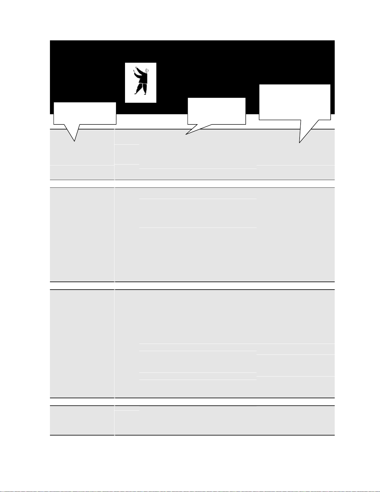
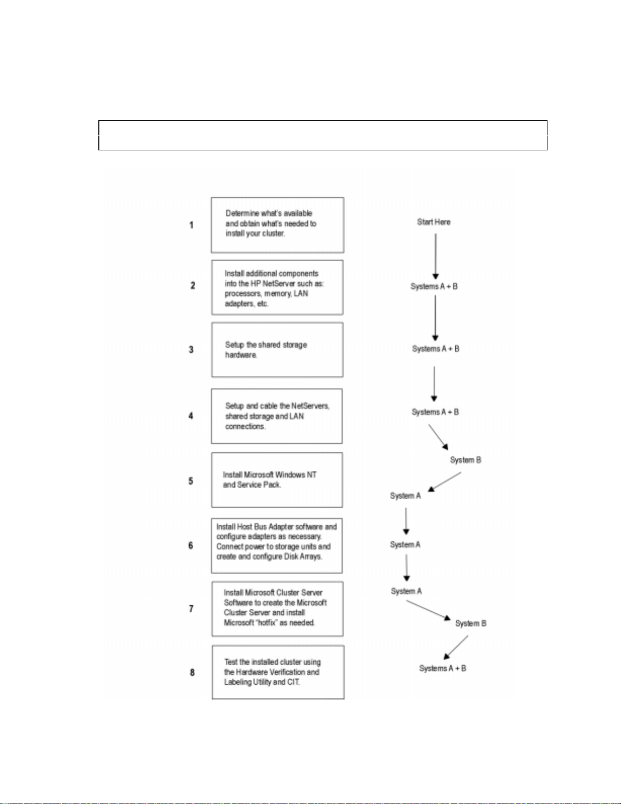
Installing a Cluster
“The Big Picture”
The Overall Tasks
Gathering Hardware,
Software, etc.
Setting Up Hardware
➮
➮
What you will be
doing!
Gather:
Hardware
Software (Windows NT, NIC drivers, etc.)
IP Addresses, subnet mask, etc.
User names, password, and domain
Tools
Install components:
into NetServers (i.e., LAN adapters)
into Shared Storage (i.e., drives)
Configure NetServer and Shared Storage:
Cabling
Switches
Etc.
Setup and cable the cluster:
Stack as standalone or racked solution
Connect device cabling
How to do it!
(See the referenced
part in the Installation
Guide)
1
What’s Needed
2
NetServers
3
Shared Storage
4
Cluster
Installing Software
Testing
➮
➮
NetServers:
Configure NetServer Hardware and BIOS
Install Windows NT
Install Service Pack
Shared Storage:
Create disk partitions
Assign Drive Letters
Format logical drives
Cluster:
Install MSCS
Reinstall Service Pack
Install HotFix (Service Pack 3 only)
Run:
Hardware Verification and Labeling Utility
Cluster Installation Test (CIT)
5
NetServers
6
Shared Storage
7
Cluster
8
Test the Cluster
Page 4

This page intentionally left blank.
Page 5
HP NetServer LXr 8000
with
HP A3661B High Availability Disk Array Model 30 / FC
Cluster Configuration Guide
13 September 1999
Introduction
This document defines the supported HP NetServer LXr 8000 and A3661B High Availability Disk Array
Model 30/FC (LXr 8000 / Model 30-FC) configurations for Microsoft Cluster Server. These configurations
minimize single points of failure (SPOF), provide maximum availability, and have been certified by
Hewlett-Packard and Microsoft. This guide is prescriptive; it describes the configurations supported by HP.
Any deviance to these configurations can result in an inoperative cluster or an operating cluster with
degraded performance, hidden SPOFs, etc., and therefore will not be supported by HP.
What’s Defined in a Racked Cluster
Cluster
SPUs
Local and Shared Storage
Intra-cluster and Client LANs
Shared Storage Cabling
Cluster
Type of SPUs HP NetServer LXr 8000
Each node must be the same model SPU, but may have different clocks
speeds, main memory sizes, cache sizes, and number of CPUs (2, 3, or 4).
Number of nodes 2
Shared Storage See Shared Storage below.
LANs:
Client LAN Any NIC that is HP and Microsoft approved. See Client LAN below.
Intra-cluster
(Heartbeat) LAN
Power source Direct from power mains, power conditioner or uninterruptible power
HP D5013A only with crossover cable. See Intra-cluster LAN below.
supply (UPS) using any power conditioner or UPS.
Page 6

System software:
Navigator version L.14.00 or later
Operating System Microsoft Windows NT Server 4.0, Enterprise Edition or later
Service pack SP3 with hotfix “clusfixi” or later
Single Points of Failure
(SPOF)
The Model 3 0/FC Disk Array virtually does not have single points of
failure. However, care should be taken to bind LUNs as described in the
Model 30/FC Disk Array manual. The manual addresses topics such as;
spreading LUNs equally across internal buses and using RAID modes. In a
cluster configuration, single points of failure arise due to the method used
to connect the disk array to the server. These single points of failure are as
follows:
•
Due to Windows NT inability to allow for dual data paths, a total
fibre-channel hub failure (removal of power from the hub, catastrophic
failure of multiple hub ports) will result in the loss of the cluster. It is
possible to power the hub using an UPS to remove part of the issue,
however an unforeseen total hub failure would still be a single point of
failure. Current data on the fibre channel hub indicates that risk in this
area is minimal.
•
If the data connection between the hub and Model 30/FC Disk Array
is broken the cluster will go down. The fibre channel cables are
generally known to be robust with an insignificant possibility of
failure.
•
A failure in the storage processor of the Model 30/FC Disk Array will
result in a loss of the cluster. The possibility of the storage processor
failing is small. Current configurations do not allow for failover to
another storage processor in the Windows NT environment.
SPU
Model HP NetServer LXr 8000
Clock speed 400 MHz. or higher
No. of CPUs 2 – 4
BIOS version Release 1 or later
CPU cache Any size
RAM 256 MB minimum. Must be HP.
No. of power supplies 3
Local storage Internal or external, using any controller except NetRAID 1 or 3. Must use
HP disks. See
I/O slots: P3 – P4 Shared storage controller
P1 – NetRAID local storage
P5 – Intra-cluster (Heartbeat) LAN
P6 – Client LAN
All others – Any other plug-in cards.
Local Storage below.
2
Page 7

Storage
Local
Physical drive location SPU internal drive bays or HP external drive cabinet (e.g., HP Rack
Storage/8 or /12)
Disk drives Must be HP
Controller SPU embedded controller or any controller, any number, manufacturer or
driver in I/O slot P1 for NetRAID local storage (except NetRAID 1 or 3).
See SPU I/O slots above.
SCSI bus Any HP cables that meet SCSI specifications and any SCSI bus speed
Shared Storage
Host Bus Adapter:
Model A5246A HP Fibre Channel Adapter Kit for NT
No. of HBA 1 – 2. (See Shared Storage Configurations.)
Driver 2.xx
SPU I/O slot P3 (1
Disk Array Controller:
Model SP630/FC Storage Processor (ordered with A3661B or A3662B)
No. of controllers 1 – 2. (See Shared Storage Configurations.)
Microcode 9.45.03 or greater
Disk Array Storage:
Model A3661B HP High Availability Disk Array Model 30/FC.
No. of cabinets See Shared Storage Configurations.
Controller 1 – 2. (See Shared Storage Configurations.)
Disk capacities: 4 GB, 8.8 GB, 17.8 GB
ArrayGUIde Version 1.7.0 or greater
RAID levels 1, 1/0, 3 and 5
Logical units Logical units within each array must be numbered from 0 – 7.
Hot spares Recommend assigning logical unit numbers 8 or greater
Power Supply 3
RAID arrays Different size or speed disks are allowed in the same RAID array but
st
HBA) and P4 (2nd HBA)
are not recommended in the same logical unit.
Shared Storage Cables (Fiber Optics)
Cables for the Short Wave
Port of either a Short or
Long Wave Hub
Cables for the Long Wave
Port of a Long Wave Hub
A3583A 2 meter FC cable,
A3531A 16 meter FC cable,
A3735A 50 meter FC cable,
A3736A 100 meter FC cable,
Any cable ≤500 meters per segment that conforms to ANSI X3.2301994 Fibre Channel Standards Specification (FC-PH) rev 4.3.
Any cable ≤2 kilometers that meets ANSI X3.230-1994 Fibre Channel
Standards Specification (FC-PH) rev 4.3.
3
Page 8

Shared Storage Configurations
Configurations:
Basic See "Basic Configuration Cabling Diagrams with Single or Cascaded
Hubs."
Redundant See "Redundant Configuration Cabling Diagrams with Single or
Cascaded Hubs."
Fibre Channel Hubs:
Model A3724A HP 10-port Short Wave Fibre Channel (FC) Hub
A4839A HP 10-port Long Wave FC Hub
No. of Hubs Basic Configuration: 1 or 2
Redundant Configuration: 2 or 4 with 1 min. or 2. max. per FC
Arbitrated Loop.
Disk Arrays (See Shared
Storage.):
No. of Disk Arrays 1-8
No. of Controllers 1 per Disk Array for Basic Configuration.
2 per Disk Array for Redundant Configura tion.
LANs
Intra-cluster (Heartbeat) LAN Client LAN
LAN connection HP D5954A crossover cable or any
equivalent
The intra-cluster LAN may only be used for
cluster node communication via a crossover
cable. It may not be used for client
communication.
NIC:
Model HP D5013A (10/100TX PCI) Any that is on both the HP
Driver 3.27.00.0001 or later (Do not enable FEC
Features.)
No. of NICs 1 1 minimum
SPU I\O slot P5 P6
Any LAN
Tested Products List and the
Microsoft Hardware
Compatibility List.
Any driver
NOTE: If the NIC used is the
same as the Intra-cluster LAN,
then the Client LAN must use the
same driver as the Intra-cluster
LAN.
4
Page 9
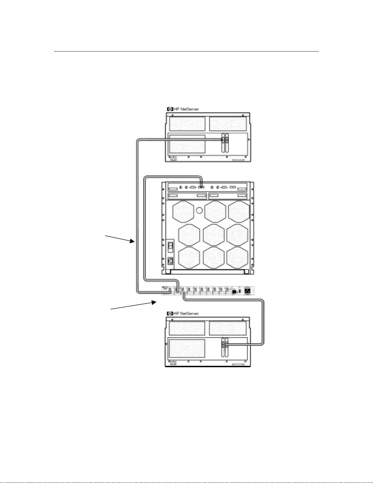
Shared Storage Cabling
This part of the guid e defines the allowable cab ling configurations for clusters using the HP NetServer
LXr 8000 and High Availability Disk Array Model 30/FC. Only these cabling configurations and cables
are supported.
See Shared
Storage Cables for
a list of cables that
can be connected
to the Short Wave
Ports of the hub.
Port connections to this
hub are for example
only. You can use any
port, except for port 10
on Long Wave Hubs.
The remaining ports can
be used for connection
of additional Disk Arrays.
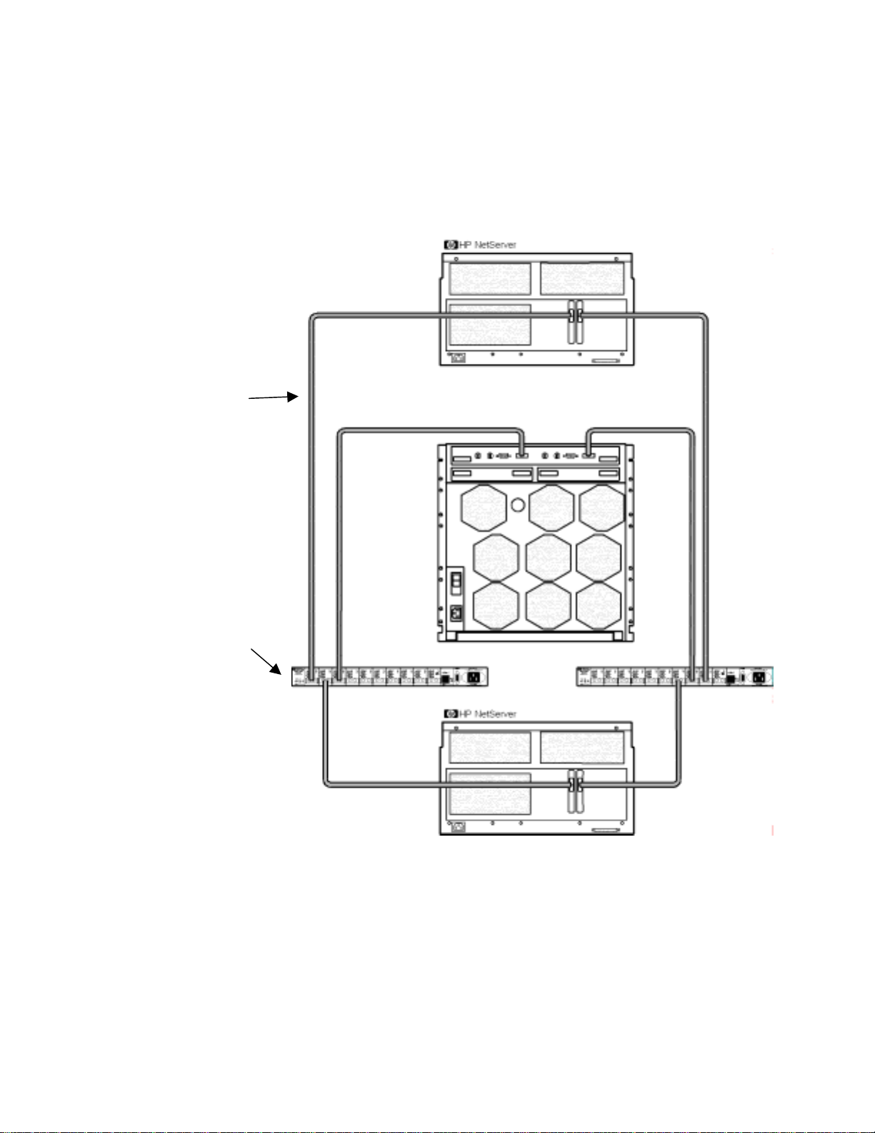
Basic Configuration w i t h Single Fibre Channel Arbitrated Loop Hub
5
Page 10
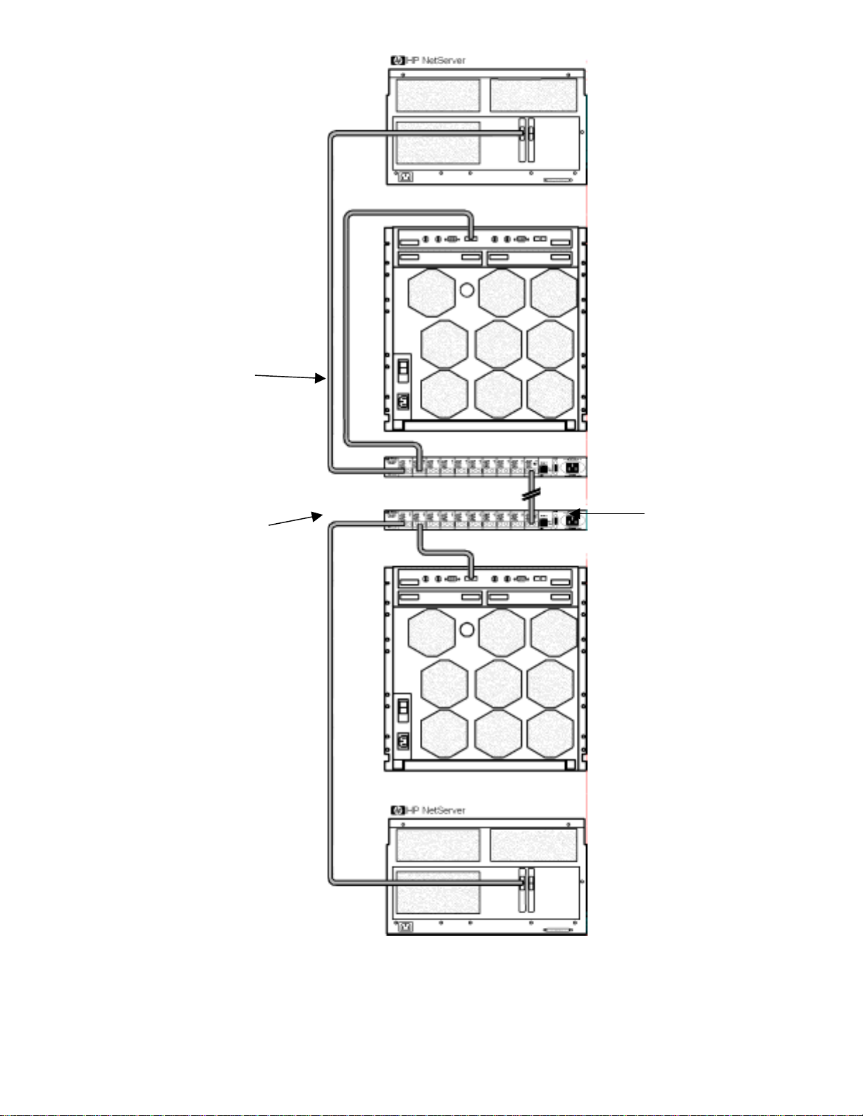
See Shared
Storage Cables for
a list of cables that
can be connected
to the Short Wave
Ports of the hub.
Port connections to
these hubs are for
example only. You can
use any port, except for
port 10 on Long Wave
Hubs. The remaining
ports can be used for
connection of additional
Disk Arrays.
See Shared Storage
Cables for a list of
cables that can be
connected between
hubs. Port 10 is used
exclusively in Long
Wave hubs for hub-tohub connection.
Basic Configuration w i t h Cascaded Fibre Channel Arbitrated Loop
Hubs
6
Page 11
See Shared
Storage Cables for
a list of cables that
can be connected
to the Short Wave
Ports of the hub.
Port connections to
these hubs are for
example only. You can
use any port, except for
port 10 on Long Wave
Hubs. The remaining
ports can be used for
connection of additional
Disk Arrays.
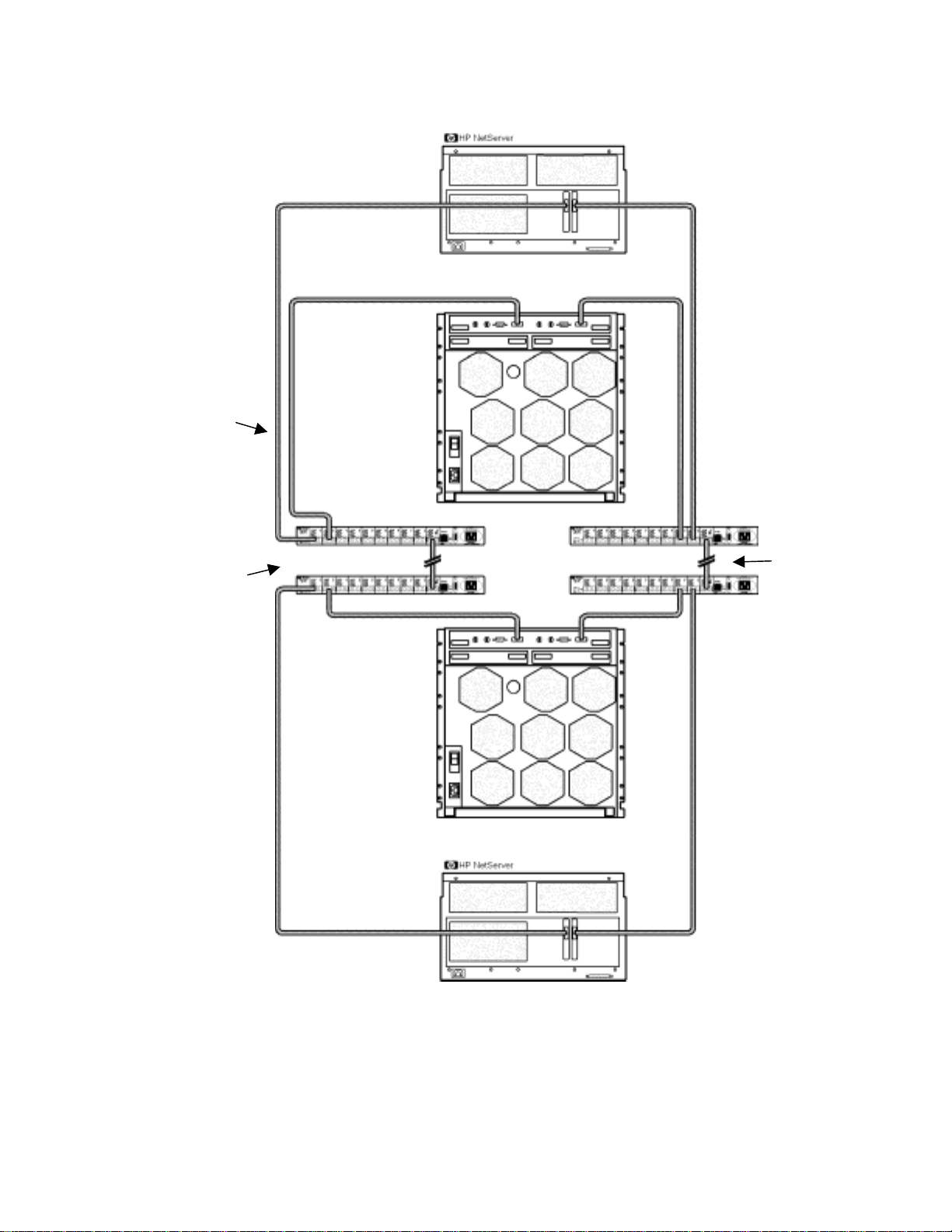
Redundant Configuration with Single Fibre Channel Arbitrated Loop Hub
7
Page 12
See Shared
Storage Cables for
a list of cables that
can be connected
to the Short Wave
Ports of the hub.
Port connections to
these hubs are for
example only. You
can use any port,
except for port 10 on
Long Wave Hubs. The
remaining ports can
be used for
connection of
additional Disk Arrays.
See Shared
Storage Cables for
a list of cables that
can be connected
between hubs.
Port 10 is used
exclusively in Long
Wave hubs for hubto-hub connection.
Redundant Configuration with Cascaded Fibre Channel Arbitrated Loop Hubs
8
Page 13

Version History
13 September 1999 In Cluster specifications added a description of "Single Points Of Failure
(SPOF) to clarify this property of the cluster.
21 April 1999 CPU speed was "400 MHz and higher" is "400 and 450 MHz only."
12 January 1999 Initial release.
9
Page 14

This page intentionally left blank.
10
Page 15

HP NetServer
Microsoft Cluster Installation Guide
with
Shared Storage System Supplement
Rack Storage/12FC
Rack Storage/12
Rack Storage/8
Storage System/6
HP AutoRAID Disk Array Model 12H
or
HP A3661B Model 30/FC High Availability Disk Array
1 September 1999
(See Version History below)
Page 16

This page intentionally left blank.
HP NetServer Installation Guide 2
Page 17

Notice
The information in this document is subject to change without notice.
Hewlett-Packard makes no warranty of any kind with regard to this material, including, but not limited to, the
implied warranties of merchantability and fitne ss for a particular purpose. Hewlett-Packard shall not be
liable for errors contained herein or for incidental or consequential damages in connection with the
furnishing, performance, or use of this material. Hewlett-Packard assumes no responsibility for the use o r
reliability of its software on equipment that is not fur nis hed by Hewlett-Packard.
Warranty
If you have any questions about the warranty for this product, contact your dealer.
Safety Considerations
The product and related documentation must be reviewed for familiarization with safety markings and
instructions before installation and operation.
Safety Symbols
A WARNING denotes a hazard that can cause personal injury.
A CAUTION denotes a hazard that can damage equipment or result in lost data.
A NOTE contains information that is useful in accomplishing a task and should be read
before performing the associated instruction(s).
Do not proceed beyond a WARNING or CAUTION notice until you understand the hazardous conditions
and have taken a ppropriate steps.
Grounding
The computer in which this product is installed is a safety class I product and has a protective earthing
terminal. There must be an uninterruptible safety earth ground from the main power source to the product’s
input wiring terminals, power cord, or supplied po wer cord set. Whene ver it is likely that the protection has
been impaired, disconnect the power cord until the ground has been restored.
Servicing
Any service, adjustment, maintenance, or repair must be performed only by authorized service-trained
personnel.
Trademark Notice
This document contains proprietary information that is protected by copyright. All rights are reserved. No
part of this document may be photocopied, reproduced, or translated to another language without the prior
written consent of Hewlett-Packard Company.
The use of trademarks or other designations is for reference purposes only. The following trademarks are
used in this manual:
• Microsoft and MS-DOS are U.S. registered trademarks of Microsoft Corp.
• Windows and Windows NT are trademarks of Microsoft Corporation.
• 3M is a registered Trademark of the 3M Company.
Hewlett-Packard
Network Server Division
10955 Tantau Avenue
Cupertino, CA 95014-0770, USA
© Copyright 1999, Hewlett-Packard Company
HP NetServer Installation Guide 3
Page 18

Contents
Some topics in this guide are applicable to all HP NetServer clusters while others are HP NetServer and
shared storage specific. A complete installation guide consists of two documents: this document (common to
all HP NetServers) and the supplement for your shared storage system.
O
VERVIEW................................................................................................................................................... 5
V
ERSION HISTORY....................................................................................................................................... 5
I
NTENDED AUDIENCE .................................................................................................................................. 5
RAPHICAL OVERVIEW TO SETTING UP THE CLUSTER ............................................................................ 6
A G
1 WHAT’S NEEDED................................................................................................................................... 7
N
EED MORE HELP?...................................................................................................................................... 8
R
EFERENCED DOCUMENTS .......................................................................................................................... 8
2 NETSERVER HARDWARE SETUP ..................................................................................................... 9
I
NSTALL COMPONENTS................................................................................................................................9
3 SHARED STORAGE HARDWARE SETUP....................................................................................... 10
4 CLUSTER CABLING AND SETUP..................................................................................................... 11
S
ETUP CLUSTER HARDWARE ..................................................................................................................... 11
C
ONNECT THE LAN ADAPTERS................................................................................................................. 11
C
ONNECT SHARED STORAGE & CABLE THE CLUSTER............................................................................... 11
5 NETSERVER SOFTWARE SETUP..................................................................................................... 12
S
TART HERE.............................................................................................................................................. 12
LCII........................................................................................................................................................... 12
LC3 ........................................................................................................................................................... 13
LH P
RO ..................................................................................................................................................... 14
LH 3.......................................................................................................................................................... 15
LH 3 (
WITH NETRAID LOCAL AND SHARED STORAGE) ........................................................................... 17
LH 4.......................................................................................................................................................... 19
LP
R............................................................................................................................................................ 21
LP
R (WITH NETRAID LOCAL AND SHARED STORAGE) ............................................................................. 23
LX/LX
R PRO............................................................................................................................................. 25
LX
R 8000.................................................................................................................................................. 26
R 8000 (WITH FIBRE CHANNEL)............................................................................................................ 28
LX
I
NSTALL SERVICE PACK FO R ALL HP NETSERVERS .................................................................................. 29
6 SHARED STORAGE SOFTWARE SETUP ........................................................................................ 31
S
HARED STORAGE SETUP .......................................................................................................................... 31
C
REATE THE ARRAY FILE SYSTEMS........................................................................................................... 31
7 MICROSOFT CLUSTER SERVER SOFTWARE SETUP................................................................37
I
NSTALL MSCS ON SYSTEM A................................................................................................................... 37
I
NSTALL MSCS ON SYSTEM B................................................................................................................... 41
I
NSTALL SERVICE PACK OR HOT FIX ......................................................................................................... 41
8 CLUSTER TESTING............................................................................................................................. 42
H
ARDWARE VERIFICATIO N AND LABELING UTILITY ................................................................................. 42
LUSTER INSTALLATION TEST................................................................................................................... 42
C
HP NetServer Installation Guide 4
Page 19

Overvie w
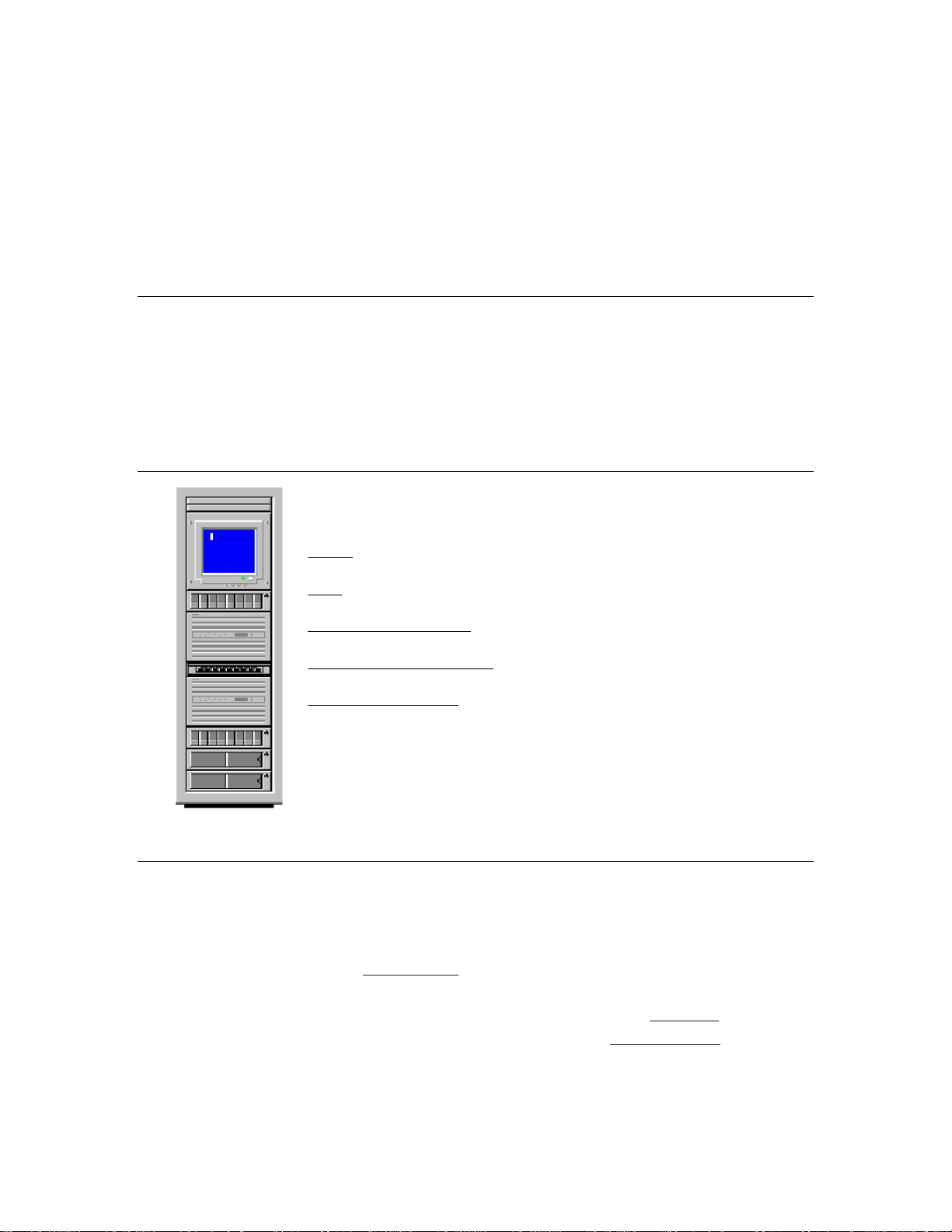
HP NetServer clusters provide increased availability solutions for critical applications. The basic cluster
consists of two HP NetServer systems coupled to shared storage units. The operating system files, application
files, and other files local to each node are stored on fixed or hot swap disks. Local disks are usually located
internally in the system.
Both HP NetServers share external drives located in the shared storage unit(s). Shared drives are accessed
using an interface card (typically referred to as the Host Bus Adapter) located in each HP NetServer unit.
Both HP NetServers run Microsoft Windows NT Server, Enterprise Edition, which includes Microsoft
Cluster Server software.
This guide has been designed to help you setup the HP NetServers, set up, assemble and cable the cluster,
and install server and cluster software.
NOTE This installation guide is incomplete without the supplement specific to your shared
storage system. When directed by this guide, turn to the supplement to get the necessary
instructions.
Version History
Date Change
1 September 99 Added installation instructions f or a fibre channel cluster solution using the LXr 8000
with the Rack Storage/12FC and up to two optional Rack Storage/12s.
7 April 99 Corrected error (changed LHI to LH4 two places in the LH4 install procedures).
Simplified the overall installation procedure by removing the need to match drive letters
for the second node.
8 March 99 Added instructions for the LPr, using NetRAID local and shared storage and Revised
instructions to use Navigator L.15.05 on LH4, LPr, and LXr 8000.
19 Jan. 99 Added installation instructions for the LPr.
18 Dec. 98 Added installation procedures for the HP NetServer LH 4 and LXr 8000.
20 Nov. 98 Revised the LH3 installation procedures in part 5 to allow using LH3 clusters with
Model 12H and FC-30 shared storage subsystems.
5 Oct. 98 Revised part 5 – Installation to provide separate server configuration and Windows NT
installation procedures. Added the LH3 installation procedure includi ng using a
NetRAID adapter for local storage.
20 July 98 Added installation instructions in part 5 for the LC3.
9 June 98 Initial release
Intended Audience
The guide is for the person who installs, administers, and troubleshoots the Microsoft Cluster Server.
Hewlett-Packard assumes this person is qualified to service computer equipment and trained to recognize
hazards in products with hazardous energy levels.
NOTE Hewlett-Packard only supports and recommends installation of clustered HP NetServer
systems using Microsoft Cluster Server software by a Microsoft or HP Cluster Certified
Installer.
HP NetServer Installation Guide 5
Page 20
A Graphical Overview to Setting Up the Cluster
CAUTION Departing from the sequence shown here can cause unnecessary work and unpredictable
results.
HP NetServer Installation Guide 6
Page 21

1 What’ s Needed
Before beginning the installatio n, make sure you have the following items prepared and tools and resources
available.
Some information in this part is shared storage specific. See part "1 What’s Needed" of the
Shared Storage Supplement and the Configuration Guide for your cluster. Review the
supplement, refer to the Configuration Guide as directed, then return to this part.
Addresses / Nam es
•
Minimum of three Client LAN IP addresses: one for each HP NetServer system and one for the HP
NetServer cluster client LAN.
•
Two Intra-cluster LAN IP addresses for the intra-cluster LAN: One for each HP NetServer system.
(May use hidden or intranet addresses. See the MSCS Ad ministrator’s Guide for a discussion of IP
addressing.)
NOTE The Client LAN IP address and Intra-cluster LAN IP addresses must be on different
subnets.
•
Cluster and node names (limited to 15 or fewer alphanumeric characters)
•
Subnet mask
•
User name, password, and domain to be used for the cluster service.
Hardware
Compare the hardware you have received with your ordering documentation, such as the parts lists created by
HP NetServer Order Assistant and Rack Assistant
Software
•
Microsoft Windows NT Server (Enterprise Edition), version 4.0, which incl udes Windows NT, version
4.0 and Service Pack (SP). See the Configuration Guide for your cluster solution for the applicable
Windows NT and SP versions and Microsoft Cluster Server installation so ft ware.
NOTE Some HP NetServers, as stated in part “5 NetServer Software Setup,” require installing
Windows NT from floppy disks. To create floppy disks, on a computer running Windows
95 or NT, insert the Windows NT Server/E base CD in the CDROM drive and from the
comm
Dnd line execute: D:\i386\winnt32.exe /ox. If needed, see, “How to Create
Windows NT Boot Floppy Disks” under Support Online for the Microsoft web site.
• Microsoft Hotfix (clusfixi.exe) for Windows NT (for SP3 only). This software is only needed if you
are using Service Pack 3. To download.
1. Access the Microsoft web site at http://www.microso ft.com.
2. On the site navigator bar, select SEARCH, then search for Q147222 in the "Support & Knowledge
Base" category.
3. On the Search Results page, select Group of Hotfixes for Exchange 5.5 and IIS 4.0, then follow the
ftp path to download the "clusfixi.exe" file.
HP NetServer Installation Guide 7
Page 22

NOTE When performing this search on the Microsoft web site you may be prompted to register
with Support Online. If prompted to register, you must first complete the questionnaire
and then complete the search.
•
HP NetServer Navigator CD. HP recommends you use the latest version, however you may use an
earlier version if it is specified in the Configuration Guide for your cluster.
•
Cluster Installation Test. Downloaded from the Certified Installer Corner under Install & Configure
on the HP NetServer Clustering Solutions web site.
•
NIC drivers. Download HP drivers from Software Downloads page under Install & Configure" on the
HP NetServer Clustering Solutions web site.
Tools
Common hand tools plus the following:
•
Torx™ T-25 driver supplied in the Rac k Installation Toolkit. For rack installed clusters only.
•
Portable Field Service Grounding Kit (3M® part number 8505, or equivalent).
Need More Help?
HP Information Assistant provides extensive support information and is available on the HP NetServer
Online Documentation CD-ROM . Although you can access HP Information Assistant from the NetServer
Navigator Main menu, HP recommends that you install it on an available Windows client connected to a
printer. For more information about installing HP Information Assistant, refer to the system documentation.
The following r eference materials may also be useful:
•
HP NetServer Microsoft Windows NT 4.0 Installatio n Guide for your HP NetServer
•
Processor Upgrade Instructions
These materials are available by choosing Install or Reference Books on the HP Information Assistant's Main
menu.
Referenced Documents
•
MSCS Administrator's Guide on the Microsoft NT 4.0 base CD under \Support\Books
•
HP NetServer Configuration Guide. If not bundled with this Installation Guide downloaded from the
Supported Configurations page under Plan on the HP Cluster Solutions web site
HP NetServer Installation Guide 8
Page 23

2 NetServer Hard ware Setup
When HP NetServers are shipped from the factory, they are configured for stand-alone operation. The first
step in creating a cluster is to install additional hardware that allows the HP NetServers to:
•
Share data
•
Communicate with one another
•
Communicate with the LAN
CAUTION Installing hardware requires opening the HP NetServers. HP therefore, recommends
using a grounding kit. See part "1 What’s Needed" for details. The kit contains a wrist
strap, anti-static mat, and cable.
Install Components
NOTE Perform the following procedure on either HP NetServer first, and then repeat the
procedure for the second NetServer.
1. Gather the required hardware components for the HP NetServers and separate the components into two
systems.
2. Remove the HP NetServer cover(s).
3. Install any of the following types of components t hat were supplied with your HP NetServers using the
instructions supplied with each component. If needed, refer to HP Information Assistant for additional
instructions:
•
Processors. If additional processors were supplied with your HP NetServers install them at this time.
•
Main Memory. Cluster operations require a minimum amount of main memory (RAM). Typically
you do not need to add memory to your HP NetServers. However, if additional memory is required,
it will be identified by the HP Order Assistant program and will be supplied. Install any additional
memory that has b een provided with your order. See the Configuration Guide for your cluster
configuration and check that you meet the minimum memory requirements.
•
LAN Adapters. Install two LAN adapters in each HP NetServer. Refer to the HP NetServer
Configuration Guide for your cluster and install the adapters in the PCI slots stated in the guide. If
other boards are installed in these slots, remove them and install them in other slots.
•
Internal Disks. If provided install the local storage drives (fixed or hot swap) into the HP
NetServers.
• Local Storage Adapter. This adapter provides the interface to the local storage of the node. See
the Configura tion Guide for yo ur cluster confi guration for the PCI slot to use.
• Host Bus (Shared Storage) Adapters. These adapters provide the interface to the Shared Storage
Systems and must be installed in specific PCI slots. See the Configuration Guide for your cluster
configuration for the HP NetServer PCI slots to use.
See instructions supplied with the component or see part "2 NetServer Hardware Setup" of
the Shared Storage Supplement for instructions on installing these adapters.
HP NetServer Installation Guide 9
Page 24

3 Shared Storage Hard ware Setup
part "3 Shared Storage Hardware Setup" in the Shared Storage Supplement
HP NetServer Installation Guide 10
Page 25

4 Cluster Cabling and Setup
Setup Cluster Hardware
Non-racked clusters - Follow the Site Preparation guidelines provided in the Planning Guide under Plan on
the HP NetServers Clustering Solutions web site.
Racked clusters - Follow the Road Map supplied with the system and instructions in the shared storage
supplement. In addition you should have rack layouts of your system printed from the HP NetServers Rack
Assistant program. If not, see HP NetServers web site to download this program.
Connect the LAN Adapters
Two sets of LAN adapters need to be connected. One set allows the cluster to communicate node-to-node
over what is typically called the intra-cluster LAN. The second set allows the cluster to communicate with
external clients over what is typically called the client LAN.
NOTE See the Configuration Guide for your cluster for the PCI slots to be used for the intra-
cluster and client LANs.
To connect the cluster’s LAN adapters:
1. Connect the intra-cluster LAN adapter in one node to the intra-cluster LAN adapter in the other node
using a crossover cable.
2. Connect the client LAN adapter in each node to the client LAN using Ethernet cables.
Connect Shared Storage & Cable the Cluster
part "4 Cluster Cabling and Setup" in the Shared Storage Supplement
HP NetServer Installation Guide 11
Page 26

5 NetServer Software Setup
Follow the procedures in this part to configure the hardware and BIOS and to install Windows NT including
the applicable Service Pack.
Start Here
In this part you will perform two major tasks. First you will configure the NetServer Hardware and BIOS
and Install Windows NT following a procedure specific to your HP NetServer as listed below. Secondly, you
will install the applicable Service Pack on the NetServer. Select your procedure from the following list:
You will… Go to procedure for… On page …
LCII
LC3
LH Pro
LH 3
LH 3 (with NetRAID local storage)
First
Second Installing the Microsoft Service Pack 30
LH 4
LPr
LPr (with NetRAID local and shared storage)
LX/LXr Pro
LXr 8000
LXr 8000 (with fibre channel)
12
13
14
15
17
19
21
25
27
28
28
LCII
Configure NetServer Hardware and BIOS
1. Make sure you power down System A and power up System B.
2. Insert the HP NetServer Navigator CD in the CD-ROM drive of System B and restart the server.
The server boots from the CD and displays the Navigator Main menu.
NOTE If prompted that the HP NetServer Navigator BIOS is a newer version, choose
Continue and go to step 3; otherwise go to step 6.
3. To update the BIOS, choose Configuration Assistant, then Custom, Microsoft, NT 4.0,
and No for automated NOS installation.
4. Select Update, then Execute. Follow screen prompts to update the BI OS.
5. After the server reboots return to the Navigator main menu by clicking the Back button twice on the
displayed window.
6. Install a utilities partition on the local storage disk by choosing Configuration Assistant, then
Custom, Microsoft, MS Windows NT 4.0 Enterprise Edition, and No for automated
NOS installation.
7. Choose Install/Update Utility Partition.
When finished, the system reboots and displays the Custom Configuration window.
HP NetServer Installation Guide 12
Page 27

Install Windows NT
1. Remove the HP NetServer Navigator CD, insert the first CD of the Microsoft Windows NT Server,
Enterprise Edition, and exit Navigator to reboot the server.
2. Select the following options when prompted:
•
Choose the unpartitioned space and install Windows NT.
•
Choose NTFS file system.
•
When prompted to search for a Network Adapter, load NIC drivers for both the intra-cluster and the
client LAN. Be sure to load the correct intra-cluster LAN driver version as specified in the
Configuration Guide for your cluster. If you are using two HP D5013A NICs, load the driver twice,
once for the intra-cluster NIC and once for the client NIC.
•
Make sure TCP/IP Protocol is selected.
Other protocols may be selected in addition, bu t TCP/IP is required.
•
Set TCP/IP Properties for DNS, WINS Address, etc. at this time.
NOTE The Client LAN IP addresses and Intra-cluster LAN IP addresses must be on different
subnets.
LC3
Configure NetServer Hardware and BIOS
1. Make sure you power down System A and power up System B.
2. Insert the HP NetServer Navigator CD in the CD-ROM drive of System B and restart the server.
The server boots from the CD and displays the Navigator Main menu.
NOTE If prompted that the HP NetServer Navigator BIOS is a newer version, choose
Continue and go to step 3; otherwise go to step 6.
3. To update the BIOS, choose Configuration Assistant and Installation Assistant,
then Custom, Microsoft, NT 4.0 and No for automated NOS installation.
4. Select Update, then Execute. Follow screen prompts to update the BI OS.
5. After the server reboots return to the Navigator main menu by clicking the Back button twice on the
displayed window.
6. Install a utilities partition on the local storage disk by choosing Configuration Assistant and
Installation Assistant, then Custom, Microsoft, MS Windows NT 4.0 Enterprise
Edition, and No for automated NOS installation.
7. Choose Install/Update Utility Partition.
When finished, the system reboots and displays the Custom Configuration window.
HP NetServer Installation Guide 13
Page 28

Install Windows NT
1. Remove the HP NetServer Navigator CD, insert the first CD of the Microsoft Windows NT Server,
Enterprise Edition, and exit Navigator to reboot the server.
2. Select the following options when prompted:
•
Choose the unpartitioned space and install Windows NT.
•
Choose NTFS file system.
•
When prompted to search for a Network Adapter, load NIC drivers for both the intra-cluster and the
client LAN. Be sure to load the correct intra-cluster LAN driver version as specified in the
Configuration Guide for your cluster. If you are using two HP D5013A NICs, load the driver twice,
once for the intra-cluster NIC and once for the client NIC.
•
Make sure TCP/IP Protocol is selected.
Other protocols may be selected in addition, bu t TCP/IP is required.
•
Set TCP/IP Properties for DNS, WINS Address, etc. at this time.
NOTE The Client LAN IP addresses and Intra-cluster LAN IP addresses must be on different
subnets.
LH Pro
1. Make sure you power down System A and power up System B.
2. Insert the HP NetServer Navigator CD in the CD-ROM drive of System B and restart the server.
The server boots from the CD and displays the Navigator Main menu.
NOTE If prompted that the HP NetServer Navigator BIOS is a newer version, choose
Continue and go to step 3; otherwise go to step 6.
3. To update the BIOS, choose Configuration Assistant, then Custom, Microsoft, MS
Windows NT 4.0 Enterprise Edition, and No for automated NOS installation.
4. Select Update, then Execute. Follow screen prompts to update the BI OS.
5. After the server reboots return to the Navigator main menu by clicking the Back button twice on the
displayed window.
6. From the Navigator Main menu, choose NetServer Utilities, then EISA Configuration
Utility.
7. In the EISA Configuration Utility, disable the Embedded IDE Hard Disk Controller.
(The embedded IDE controller is not used on HP NetServer sys t ems.)
8. Save and exit the EISA Configuration Utility.
The Utility saves your configuratio n data, restarts the HP NetServer and reloads the HP Navigator CD-
ROM.
9. Install a utility partition on the local stor age disk by choosing Configuration Assistant, then
Custom, Microsoft, MS Windows NT 4.0 Enterprise Edition, and No for automated
NOS installation.
10. Choose Install/Update Utility Partition.
When finished, the system reboots and displays the Custom Configuration window.
HP NetServer Installation Guide 14
Page 29

Install Windows NT
1. Remove the HP NetServer Navigator CD, insert the first CD of the Microsoft Windows NT Server,
Enterprise Edition, and exit Navigator to reboot the server.
2. Select the following options when prompted:
•
Choose the unpartitioned space and install Windows NT.
•
Choose NTFS file system
•
When prompted to search for a Network Adapter, load NIC drivers for both the intra-cluster and the
client LAN. Be sure to load the correct intra-cluster LAN driver version as specified in the
Configuration Guide for your cluster. If you are using two HP D5013A NICs, load the driver twice,
once for the intra-cluster NIC and once for the client NIC.
•
Make sure TCP/IP Protocol is selected.
Other protocols may be selected in addition, bu t TCP/IP is required.
•
Set TCP/IP Properties for DNS, WINS Address, etc. at this time.
NOTE The Client LAN IP addresses and Intra-cluster LAN IP addresses must be on different
subnets.
LH 3
These procedures provide instructions for servers using NetRAID, AutoRAID Model 12H, and Model 30/FC
shared storage solutions.
NOTE If you are use NetRAID adapters for both shared and local storage go to the next
procedure, LH3 (with NetRAID Local and Shared Storage) on page 17.
Configure NetServer Hardware and BIOS
1. Make sure you power down System A and power up System B.
2. Insert the HP NetServer Navigator CD in the CD-ROM drive and restart the server.
3. During reboot enter the Setup Utility by pressing F2.
4. Select User Preferences and then the LH4 Integrated NetRAID setting you want to use.
If you are using NetRAID for shared storage, disable the LH4 Integrated HP NetRAID.
It must be disabled otherwise it will conflict with the HP NetRAID adapter used for shared storage.
5. Exit the Setup Utility.
The server reboots. If you have special NetServer local SCSI bus options enter the Symbios utility, by
pressing Ctrl+C at the Symbios boot banner during reboot and set the options you need; otherwise allow
the server to reboot. The server boots from the CD and displays the Navigator Main menu.
NOTE If prompted that the HP NetServer Navigator BIOS is a newer version, choose
Continue and go to step 6; otherwise go to step 9.
6. To update the BIOS, choose Configuration Assistant and Installation Assistant,
then Custom, Microsoft, MS Windows NT 4.0 Enterprise Edition, and No for
automated NOS installation.
7. Select Update, then Execute. Follow screen prompts to update the BI OS.
HP NetServer Installation Guide 15
Page 30

8. After the server reboots, return to the Navigator main menu by clicking the Back button twice on the
displayed window.
9. From the Navigator main menu, install a utility partition on the local storage disk by choosing
Configuration Assistant and Installation Assistant, then Custom,
Microsoft, MS Windows NT 4.0 Enterprise Edition, and No for automated NOS
installation.
10. Choose Install/Update Utility Partition.
When finished, the system reboots and displays the Custom Configuration window.
11. Make an NT 4.0 Drivers disk by choosing Create Driver Diskette(s), Execute, and
following the prompts. Label the floppy disk NT 4.0 Drivers.
Install Windows NT
NOTE Windows NT must be installed from floppy disks, not the CD, so that the mass storage
drivers will be loaded correctly. If you have not created a set of Windows NT boot
floppy disks, see Software in part “1 What’s Needed” for additional information.
1. Remove the HP NetServer Navigator CD, insert the boot floppy for Windows NT4.0, and exit Navigator
to reboot the server.
2. When Setup prompts to detect mass storage devices, skip detection and manually specify the mass
storage drivers:
•
The drivers are loaded from the NT 4.0 Drivers floppy disk you created from the Navigator CD.
•
First, load the driver for the device you want to boot from. For drives in the LH 3 internal bays this
will normally be the embedded SCSI Symbios driver.
•
Secondly, load the IDE driver, since the CD drive is on the IDE bus.
•
Finally, load any other mass storage drivers you need. If you are using NetRAID for shared storage
do not load the HP NetRAID driver at this time. It will be loaded later.
3. Continue the installation, inserting floppy disks #2 and #3 and select the following options when
prompted:
•
Choose the unpartitioned space and install Windows NT.
•
Choose NTFS file system
•
When prompted to search for a Network Adapter, load NIC drivers for both the intra-cluster and the
client LAN. Be sure to load the correct intra-cluster LAN driver version as specified in the
Configuration Guide for your cluster. If you are using two HP D5013A NICs, load the driver twice,
once for the intra-cluster NIC and once for the client NIC.
•
Make sure TCP/IP Protocol is selected.
Other protocols may be selected in addition, bu t TCP/IP is required.
• If you are using two HP D5013A NICs, when prompted for TCP/IP Properties:
Make sure adapter [2] is highlighted and specify its IP address and subnet mask. This will be the
LAN adapter for the intra-cluster LAN.
Select adapter [1] and specify its IP address and subnet mask. This will be the LAN adapter for the
client LAN.
Set TCP/IP Properties for DNS, WINS Address, etc. at this time.
HP NetServer Installation Guide 16
Page 31

NOTE The Client LAN IP addresses and Intra-cluster LAN IP addresses must be on different
subnets.
4. Once the NT installation is complete, the D5013A NIC drivers must be manually set to the correct LAN
speed. Log on and from the start menu select: Settings, Control Panel, Network, and
Adapters. For each D5013A adapter, select Properties then Settings and set the network
speed to the appropriate setting (either 10 Mbps or 100 Mbps) for your network. The intra-cluster LAN
should be set to 100 Mbps. Do not use the Auto setting.
LH 3 (with NetRAID Local and Shar ed Storage)
A NetRAID adapter may only be used for either shared storage or local storage; one adapter may not be used for
both. To use NetRAID adapters for both shared and local storage, you must use two adapters.
Configure NetServer Hardware and BIOS
1. Make sure you power down System A and power up System B.
2. Insert the HP NetServer Navigator CD in the CD-ROM drive and restart the server.
3. During reboot enter the Setup Utility by pressing F2.
4. Using the Setup Utility disable the LH3 Integrated NetRAID.
Integrated NetRAID is not used in a cluster because it conflicts with the HP NetRAID adapter used for
shared storage.
NOTE Auto IRQ assignments can give IRQ conflicts. If this occurs manually set the IRQ
assignments. In Configuration, PCI Slot Devices, PCI IRQ Locking,
assign the IRQs to the cards. The following assignments work for the standard
configuration:
Card PCI Slot
NIC P1 9
NIC P2 9
NetRAID P7 5
NetRAID P8 5
- SCSI A 10 (or disabled)
- SCSI B 10 (or disabled)
Disable SCSI A and SCSI B if they are not used!
Set any other options as you desire.
5. Exit the Setup Utility
The server reboots. If you have special NetServer local SCSI bus options enter the Symbios utility, by
pressing Ctrl+C at the Symbios boot banner during reboot and set the options you need; otherwise allow
the server to reboot. The server boots from the CD and displays the Navigator Main menu.
NOTE If prompted that the HP NetServer Navigator BIOS is a newer version, choose
Continue and go to step 6; otherwise go to step 9.
6. To update the BIOS, choose Configuration Assistant and Installation Assistant,
then Custom, Microsoft, MS Windows NT 4.0 Enterprise Edition, and No for
automated NOS installation.
7. Select Update, then Execute. Follow screen prompts to update the BI OS.
8. After the server reboots, return to the Navigator main menu by clicking the Back button twice on the
displayed window.
IRQ
HP NetServer Installation Guide 17
Page 32

9. From the Navigator main menu selec t , Configuration Assistant, then Custom, Microsoft,
MS Windows NT 4.0 Enterprise Edition, and No. Check the advisories in Configuration
Advisor for IRQ conflicts and other problems. Click Continue.
10. Define the local storage RAID arrays. Select Configure Disk Array and use HP NetRAID
Assistant to define the arrays. Be sure to define the arrays for the local storage adapter (Adapter_0), not
the shared storage adapter (Adapter_1).
NOTE DO NOT define the shared storage arrays at this time. They will be defined later.
11. From the Navigator main menu install a utility partition on the local sto r age disk by choosing
Configuration Assistant and Installation Assistant, then Custom,
Microsoft, MS Windows NT 4.0 Enterprise Edition, and No for automated NOS
installation.
12. Choose Install/Update Utility Partition.
When finished, the system reboots and displays the Custom Configuration window.
13. Make an NT 4.0 Drivers floppy disk by choosing Create Driver Diskette(s), Execute,
and following the prompts. Label the floppy disk NT 4.0 Drivers.
Copy the NetRAID Driver for Clusters
Copy the “Mraidnt.sys” file from the NR Firmware & Driver floppy disk to the “\Netraid” directory on the
NT 4.0 Drivers floppy disk you created in step 13 above (page 18). You can do this either by booting the
server on which you are installing to DOS and copying the file, or by copying this file using another
computer:
This will overwrite the NetRAID single system driver already there with the NetRAID cluster driver.
NOTE Do not copy the oemsetup.inf file on the NR Firmware & Driver floppy disk.
Install Windows NT
NOTE Windows NT must be installed from floppy disks, not the CD, so that the mass storage
drivers will be loaded correctly. If you have not created a set of Windows NT boot
floppy disks, see Software in part “1 What’s Needed” for additional information.
1. Insert the boot floppy for Windows NT4.0 and exit Navigator to reboot the server.
2. When Setup prompts to detect mass storage devices, skip detection and manually specify the mass
storage drivers:
3. Load drivers using the NT 4.0 Drivers floppy disk you created in step 13 above (page 18).
• Load the driver for the device you want to boot from. This will be the HP NetRAID Adapter Driver.
• Load the IDE driver, since the CD drive is on the IDE bus.
• Load any other mass storage drivers you need. If you are using the embedded SCSI channels, load
the Symbios driver at this time.
4. Continue the installation and select the following options when prompted:
• Choose the unpartitioned space and install Windo ws NT.
• Choose NTFS file system
HP NetServer Installation Guide 18
Page 33

•
When prompted to search for a Network Adapter, load NIC drivers for both the intra-cluster and the
client LAN. Be sure to load the correct intra-cluster LAN driver version as specified in the
Configuration Guide for your cluster. If you are using two HP D5013A NICs, load the driver twice,
once for the intra-cluster NIC and once for the client NIC.
•
Make sure TCP/IP Protocol is selected.
Other protocols may be selected in addition, bu t TCP/IP is required.
•
If you are using two HP D5013A NICs, when prompted for TCP/IP Properties:
Make sure adapter [2] is highlighted and specify its IP address and subnet mask. This will be the
LAN adapter for the intra-cluster LAN.
Select adapter [1] and specify its IP address and subnet mask. This will be the LAN adapter for the
client LAN.
Set TCP/IP Properties for DNS, WINS Address, etc. at this time.
NOTE The Client LAN IP addresses and Intra-cluster LAN IP addresses must be on different
subnets.
5. Once the NT installation is complete, the D5013A NIC drivers must be manually set to the correct LAN
speed. Log on and from the start menu select: Settings, Control Panel, Network, and
Adapters. For each D5013A adapter, select Properties then Settings and set the network
speed to the appropriate setting (either 10 Mbps or 100 Mbps) for your network. The intra-cluster LAN
should be set to 100 Mbps. Do not use the Auto setting.
LH 4
These procedures provide instructions for servers using NetRAID, AutoRAID Model 12H, and Model 30/FC
shared storage solutions.
Configure NetServer Hardware and BIOS
6. Make sure you power down System A and power up System B.
7. Insert the HP NetServer Navigator CD in the CD-ROM drive and restart the server.
8. During reboot enter the Setup Utility by pressing F2.
9. Select User Preferences and then the LH4 Integrated NetRAID setting you want to use.
If you are using NetRAID for shared storage, disable the LH4 Integrated HP NetRAID.
It must be disabled otherwise it will conflict with the HP NetRAID adapter used for shared storage.
10. Exit the Setup Utility (F10, Save, and Exit).
The server reboots. If you have special NetServer local SCSI bus options enter the Symbios utility, by
pressing Ctrl+C at the Symbios boot banner during reboot and set the options you need; otherwise allow
the server to reboot. The server boots from the CD and displays the Navigator Main menu.
NOTE If prompted that the HP NetServer Navigator BIOS is a newer version, choose
Continue and go to step 6; otherwise go to step 9.
11. To update the BIOS, choose Configuration Assistant and Installation Assistant,
then Custom, Microsoft, MS Windows NT 4.0 Enterprise Edition, and No for
automated NOS installation.
HP NetServer Installation Guide 19
Page 34

12. Select Update, then Execute. Follow screen prompts to update the BIOS.
13. After the server reboots, return to the Navigator main menu by clicking the Back button twice on the
displayed window.
14. From the Navigator main menu, install a utility partition on the local storage disk by choosing
Configuration Assistant and Installation Assistant, Custom, Microsoft,
then either:
•
MS Windows NT4.0 Enterprise Edition Cluster Server if using Navigato r if
L.15.05 or later.
•
MS Windows NT 4.0 Enterprise Edition, and No for automated NOS installation if
using Navigator L.15.04 or earlier.
15. Choose Install/Update Utility Partition.
When finished, the system reboots and displays the Custom Configuration window.
16. Make a NT4.0 Drivers floppy disk by choosing Create Driver Diskette(s), Execute, and
following the prompts. Label the floppy disk NT 4.0 Drivers.
17. Return to the Navi gator main menu by clicking the Back butto n three times.
Install Windows NT
NOTE Windows NT must be installed from floppy disks, not the CD, so that the mass storage
drivers will be loaded correctly. If you have not created a set of Windows NT boot
floppy disks, see Software in part “1 What’s Needed” in the installation guide supplement
for additional information.
18. Insert the boot floppy disk for Windows NT4.0 and exit Navigator to reboot the server.
19. When Windows NT Setup prompts to detect mass storage devices, skip detection and manually specify
the mass storage drivers:
•
The drivers are loaded from the NT 4.0 Drivers floppy disk you created from the Navigator CD.
•
First, load the driver for the device you want to boot from. For drives in the LH 4 internal bays this
will normally be the embedded SCSI Symbios driver.
•
Secondly, load the IDE driver, since the CD drive is on the IDE bus.
•
Finally, load any other mass storage drivers you need. If you are using NetRAID for shared storage
do not load the HP NetRAID driver at this time. It will be loaded later.
20. Continue the installation using floppy disks#2 and #3 and select the following options when prompted:
•
Choose the unpartitioned space and install Windows NT.
•
Choose NTFS file system
• When prompted to search for a Network Adapter, load NIC drivers for both the intra-cluster and the
client LAN. Be sure to load the correct intra-cluster LAN driver version as specified in the
Configuration Guide for your cluster. If you are using two HP D5013A NICs, load the driver twice,
once for the intra-cluster NIC and once for the client NIC.
• Make sure TCP/IP Protocol is selected.
Other protocols may be selected in addition, bu t TCP/IP is required.
HP NetServer Installation Guide 20
Page 35

•
If you are using two HP D5013A NICs, when prompted for TCP/IP Properties:
Make sure adapter [2] is highlighted and specify its IP address and subnet mask. This will be the
LAN adapter for the intra-cluster LAN.
Select adapter [1] and specify its IP address and subnet mask. This will be the LAN adapter for the
client LAN.
Set TCP/IP Properties for DNS, WINS Address, etc. at this time.
NOTE The Client LAN IP addresses and Intra-cluster LAN IP addresses must be on different
subnets.
21. Once the NT installation is complete, the D5013A NIC drivers must be manually set to the correct LAN
speed. Log on and from the start menu select: Settings, Control Panel, Network, and
Adapters. For each D5013A adapter, select Properties then Settings and set the network
speed to the appropriate setting (either 10 Mbps or 100 Mbps) for your network. The intra-cluster LAN
should be set to 100 Mbps. Do not use the Auto setting.
LPr
These procedures provide instructions for servers using NetRAID and AutoRAID shared storage solutions.
NOTE If you are use NetRAID adapters for both shared and local storage go to the next
procedure, LPr (with NetRAID Local and Shared Storage) on page 25.
Configure NetServer Hardware and BIOS
1. Make sure you power down System A and power up System B.
2. Insert the HP NetServer Navigator CD in the CD-ROM drive and restart the server.
3. If you have special NetServer local SCSI bus options enter the Symbios utility by pressing Ctrl+C at the
Symbios boot banner during boot and set the options you need; otherwise allow the server to boot. The
server boots from the CD and displays the Navigator Main Menu.
NOTE If prompted that the HP NetServer Navigator BIOS is a newer version, choose
Continue and go to step 4; otherwise go to step 6.
4. To update the BIOS, choose NetServer Utilities | More NetServer Utilities |
BIOS Update Utility. Select Execute and follow the screen prompts to update the B IOS.
5. After the server reboots, return to the Navigator main menu by clicking the Back button twice on the
displayed window.
6. From the Navigator main menu, install a utility partition on the local storage disk by choosing
Configuration Assistant and Installation Assistant, Custom, Microsoft,
then either:
• MS Windows NT4.0 Enterprise Edition Cluster Server if using Navigato r if
L.15.05 or later.
• MS Windows NT 4.0 Enterprise Edition, and No for automated NOS installation if
using Navigator L.15.04 or earlier.
HP NetServer Installation Guide 21
Page 36

7. Choose Install/Update Utility Partition and Execute.
When finished, the system reboots and displays the Custom Configuration window.
8. Make an NT 4.0 Drivers floppy disk by choosing Create Driver Diskette(s), Execute,
and following the prompts. Label the floppy disk NT 4.0 Drivers.
9. Press the Back button three times to return the Navigator Main Menu.
10. If you are using a NetRAID adapter for either shared or local storage, create a set of installation floppy
disks for NetRAID Assi stant by choosing NetServer Utilities | Diskette Library.
Select NetRAID Assistant for WindowsNT and Windows95 from the list and then the
Execute button. Follow the instructions to create the NetRAID Assistant installation floppy disks.
Label the floppy disks HP NetRAID Assistant 1 and HP NetRAID Assistant 2.
Install Windows NT
NOTE Windows NT must be installed from floppy disks, not the CD, so that the mass storage
drivers will be loaded correctly. If you have not created a set of Windows NT boot
floppy disks, see Software in part “1 What’s Needed” for additional information.
1. Remove the HP NetServer Navigator CD, insert the boot floppy for Windows NT4.0, and exit Navigator
to reboot the server.
2. When Setup prompts to detect mass storage devices, skip detection and manually specify the mass
storage drivers:
•
The drivers are loaded from the NT 4.0 Drivers floppy disk you created from the Navigator CD.
•
First, load the driver for the device you want to boot from. For drives in the LPr internal bays this
will normally be the embedded SCSI Symbios driver on the drivers disk. Select "SCSI Symbios
driver for the HP NetServer LPr."
•
Secondly, load the IDE driver, since the CD drive is on the IDE bus.
•
Finally, load any other mass storage drivers you need. If you are using NetRAID for shared storage
do not load the HP NetRAID driver at this time. It will be loaded later.
3. Continue the installation, inserting floppy disk #3 and select the following options when prompted:
•
Choose the unpartitioned space and install Windows NT.
•
Choose NTFS file system
•
When prompted to search for a Network Adapter, load NIC drivers for both the intra-cluster and the
client LAN. Be sure to load the correct intra-cluster LAN driver version as specified in the
Configuration Guide for your cluster. If you are using two HP D5013A NICs, load the driver twice,
once for the intra-cluster NIC and once for the client NIC.
•
Make sure TCP/IP Protocol is selected.
Other protocols may be selected in addition, bu t TCP/IP is required.
• If you are using two HP D5013A NICs, when prompted for TCP/IP Properties:
Make sure adapter [2] is highlighted and specify its IP address and subnet mask. This will be the
LAN adapter for the intra-cluster LAN.
Select adapter [1] and specify its IP address and subnet mask. This will be the LAN adapter for the
client LAN.
Set TCP/IP Properties for DNS, WINS Address, etc. at this time.
HP NetServer Installation Guide 22
Page 37

NOTE The Client LAN IP addresses and Intra-cluster LAN IP addresses must be on different
subnets.
4. Once the NT installation is complete, the D5013A NIC drivers must be manually set to the correct LAN
speed. Log on and from the start menu select: Settings, Control Panel, Network, and
Adapters. For each D5013A adapter, select Properties then Settings and set the network
speed to the appropriate setting (either 10 Mbps or 100 Mbps) for your network. The intra-cluster LAN
should be set to 100 Mbps. Do not use the Auto setting.
LPr (with NetRAID Local and Shared Storage)
A NetRAID adapter may only be used for either shared storage or local storage; one adapter may not be used for
both. To use NetRAID adapters for both shared and local storage, you must use two adapters.
Configure NetServer Hardware and BIOS
1. Make sure you power down System A and power up System B.
2. Insert the HP NetServer Navigator CD in the CD-ROM drive and restart the server.
3. If you have special NetServer local SCSI bus options enter the Symbios utility by pressing Ctrl+C at the
Symbios boot banner during boot and set the options you need; otherwise allow the server to boot. The
server boots from the CD and displays the Navigator Main Menu.
NOTE If prompted that the HP NetServer Navigator BIOS is a newer version, choose
Continue and go to step 4; otherwise go to step 6.
4. To update the BIOS, choose NetServer Utilities | More NetServer Utilities |
BIOS Update Utility. Select Execute and follow the screen prompts to update the B IOS.
5. After the server reboots, return to the Navigator main menu by clicking the Back button twice on the
displayed window.
6. From the Navigator main menu, install a utility partition on the local storage disk by choosing
Configuration Assistant and Installation Assistant, Custom, Microsoft,
then either:
•
MS Windows NT4.0 Enterprise Edition Cluster Server if using Navigato r if
L.15.05 or later.
•
MS Windows NT 4.0 Enterprise Edition, and No for automated NOS installation if
using Navigator L.15.04 or earlier.
7. Define the local storage RAID arrays. Select Configure Disk Array and use HP NetRAID
Assistant to define the arrays. Be sure to define the arrays for the local storage adapter (Adapter_0), not
the shared storage adapter (Adapter_1).
NOTE DO NOT define the shared storage arrays at this time. They will be defined later.
8. Exit HP NetRAID Assistant. The server will reboot.
During the reboot, at the NetRAID banner press <Ctrl><M> to enter the NetRAID Express utility.
From the Management Menu, check that the BIOS is enabled. If it is not, enable it.
9. Exit the NetRAID Express utility and reboot. Navigator will return to the Custom Configuration screen.
Install a utility partition on the local stor age disk by choosing Install/Update Utility
Partition.
After installing the utility partition, Navigator returns to the Custom Configuration screen.
HP NetServer Installation Guide 23
Page 38

10. Make an NT 4.0 Drivers floppy disk by choosing Create Driver Diskette(s), Execute,
and following the prompts. Label the floppy disk NT 4.0 Drivers.
11. Press the Back button three times to return the Navigator Main Menu.
12. Create a set of installation floppy disks for NetRAID Assistan t by choosing NetServer Utilities
| Diskette Library. Select NetRAID Assistant for WindowsNT and Windows95
from the list and then the Execute button. Follow the instructio ns to create the NetRAID Assistant
installation floppy disks. Label the floppy disks HP NetRAID Assistant 1 and HP NetRAID Assistant 2.
Install Windows NT
NOTE Windows NT must be installed from floppy disks, not the CD, so that the mass storage
drivers will be loaded correctly. If you have not created a set of Windows NT boot
floppy disks, see Software in part “1 What’s Needed” for additional information.
1. Remove the Navigator CD, insert the boot floppy for Windows NT4.0, and exit Navigator to reboot the
server.
2. When Setup prompts to detect mass storage devices, skip detection and manually specify the mass
storage drivers:
3. Load drivers using the NetRAID-3Si Cluster Firmware and Driver floppy disk you created in part 1
“What’s Needed” and the NT 4.0 Drivers floppy disk you created in step 10 above of this procedure.
•
Load the driver for the device you want to boot from. This will be the HP NetRAID Adapter Driver.
If you are using a NetRAID-3Si Adapter for shared storage, load this driver from the NetRAID-3Si
Cluster Firmware and Driver floppy disk. Be sure to use the driver version specified for shared
storage in the Configuration Guide, since this driver is used for both the NetRAID local storage
adapter and the NetRAID-3Si shared storage adapter.
•
Load the IDE driver from the NT 4.0 Drivers floppy disk, since the CD drive is on the IDE bus.
•
Load any other mass storage drivers you need. If you are using the embedded SCSI channel, load
the Symbios driver from the NT 4.0 Drivers floppy disk at this time.
4. Continue the installation and select the following options when prompted:
•
Choose the unpartitioned space and install Windows NT.
•
Choose NTFS file system
•
When prompted to search for a Network Adapter, load NIC drivers for both the intra-cluster and the
client LAN. Be sure to load the correct intra-cluster LAN driver version as specified in the
Configuration Guide for your cluster. If you are using two HP D5013A NICs, load the driver twice,
once for the intra-cluster NIC and once for the client NIC.
• Make sure TCP/IP Protocol is selected.
Other protocols may be selected in addition, bu t TCP/IP is required.
• If you are using two HP D5013A NICs, when prompted for TCP/IP Properties:
Make sure adapter [2] is highlighted and specify its IP address and subnet mask. This will be the
LAN adapter for the intra-cluster LAN.
Select adapter [1] and specify its IP address and subnet mask. This will be the LAN adapter for the
client LAN.
Set TCP/IP Properties for DNS, WINS Address, etc. at this time.
HP NetServer Installation Guide 24
Page 39

NOTE The Client LAN IP addresses and Intra-cluster LAN IP addresses must be on different
subnets.
5. Once the NT installation is complete, the D5013A NIC drivers must be manually set to the correct LAN
speed. Log on and from the start menu select: Settings, Control Panel, Network, and
Adapters. For each D5013A adapter, select Properties then Settings and set the network
speed to the appropriate setting (either 10 Mbps or 100 Mbps) for your network. The intra-cluster LAN
should be set to 100 Mbps. Do not use the Auto setting.
LX/LXr Pro
Configure NetServer Hardware and BIOS
1. Make sure you power down System A and power up System B.
2. Insert the HP NetServer Navigator CD in the CD-ROM drive of System B and restart the server.
The server boots from the CD and displays the Navigator Main menu.
NOTE If prompted that the HP NetServer Navigator BIOS is a newer version, choose
Continue and go to step 3; otherwise go to step 6.
3. To update the BIOS, choose Configuration Assistant, then Custom, Microsoft, MS
Windows NT 4.0 Enterprise Edition, and No for automated NOS installation.
4. Select Update, then Execute. Follow screen prompts to update the BI OS.
5. After the server reboots return to the Navigator main menu by clicking the Back button twice on the
displayed window.
6. From the Navigator Main menu, choose NetServer Utilities, then EISA Configuration
Utility.
7. At the Utility window select Step 3 - View or Edit Details and:
•
Make sure MP Spec Version is set to V1.4.
•
Disable the on-board IDE Hard Disk Controller by scrolling to On-board IDE Hard Disk
Controller, pressing Enter, and choosing Disable.
The embedded IDE controller is not used on the HP NetServer LX and LXr Pro.
8. Save and exit the EISA Configuration Utility.
The utility saves the configuration data, restarts the server, and reloads the HP NetServer Navigator CD.
9. Install a utility partition on the local stor age disk by choosing Configuration Assistant, then
Custom, Microsoft, MS Windows NT 4.0 Enterprise Edition, and No for automated
NOS installation.
10. Choose Install/Update Utility Partition.
When finished, the system reboots and displays the Custom Configuration window.
Install Windows NT
1. Remove the HP NetServer Navigator CD, insert the first CD of the Microsoft Windows NT Server,
Enterprise Edition, and exit Navigator to reboot the server.
2. Select the following options when prompted:
• Choose the unpartitioned space and install Windo ws NT.
• Choose NTFS file system
HP NetServer Installation Guide 25
Page 40

•
When prompted to search for a Network Adapter, load NIC drivers for both the intra-cluster and the
client LAN. Be sure to load the correct intra-cluster LAN driver version as specified in the
Configuration Guide for your cluster. If you are using two HP D5013A NICs, load the driver twice,
once for the intra-cluster NIC and once for the client NIC.
•
Make sure TCP/IP Protocol is selected.
Other protocols may be selected in addition, bu t TCP/IP is required.
•
Set TCP/IP Properties for DNS, WINS Address, etc. at this time.
NOTE The Client LAN IP addresses and Intra-cluster LAN IP addresses must be on different
subnets.
LXr 8000
These procedures provide instructions for servers using NetRAID, AutoRAID Model 12H, and Model 30/FC
shared storage solutions
Configure NetServer Hardware and BIOS
1. Make sure you power down System A and power up System B.
2. Insert the HP NetServer Navigator CD in the CD-ROM drive and restart the server.
NOTE If prompted that the HP NetServer Navigator BIOS is a newer version, choose
Continue and go to step 3; otherwise go to step 6.
3. To update the BIOS, choose Configuration Assistant, then Custom, Microsoft, MS
Windows NT 4.0 Enterprise Edition, and No for automated NOS installation.
4. Select Update, then Execute. Follow screen prompts to update the BI OS.
5. After the server reboots, return to the Navigator main menu by clicking the Back button twice on the
displayed window.
6. From the Navigator main menu, install a utility partition on the local storage disk by choosing
Configuration Assistant and Installation Assistant, Custom, Microsoft,
then either:
•
MS Windows NT4.0 Enterprise Edition Cluster Server if using Navigato r if
L.15.05 or later.
•
MS Windows NT 4.0 Enterprise Edition, and No for automated NOS installation if
using Navigator L.15.04 or earlier.
7. Choose Install/Update Utility Partition.
When finished, the system reboots and displays the Custom Configuration window.
8. Make an NT 4.0 Drivers floppy disk by choosing Create Driver Diskette(s), Execute, and
following the prompts. Label the floppy disk NT 4.0 Drivers.
HP NetServer Installation Guide 26
Page 41

Install Windows NT
NOTE Windows NT must be installed from floppy disks, not the CD, so that the mass storage
drivers will be loaded correctly. If you have not created a set of Windows NT boot
floppy disks, see Software in part “1 What’s Needed” for additional information.
1. Insert the boot floppy disk for Windows NT4.0 and exit Diagnostic Assistant to reboot the server.
2. When Setup prompts to detect mass storage devices, skip detection and manually specify the mass
storage drivers:
•
The drivers are loaded from the NT 4.0 Drivers floppy disk you created from the Navigator CD.
•
First, load the driver for the device you want to boot from. For drives in the LXr 8000 internal bays
this will normally be the embedded SCSI Symbios driver.
•
Secondly, load the IDE driver, since the CD drive is on the IDE bus.
•
Finally, load any other mass storage drivers you need. If you are using NetRAID for shared storage
do not load the HP NetRAID driver at this time. It will be loaded later.
3. Continue the installation and select the following options when prompted:
•
Choose the unpartitioned space and install Windows NT.
•
Choose NTFS file system
•
When prompted to search for a Network Adapter, load NIC drivers for both the intra-cluster and the
client LAN. Be sure to load the correct intra-cluster LAN driver version as specified in the
Configuration Guide for your cluster. If you are using two HP D5013A NICs, load the driver twice,
once for the intra-cluster NIC and once for the client NIC.
•
Make sure TCP/IP Protocol is selected.
Other protocols may be selected in addition, bu t TCP/IP is required.
•
If you are using two HP D5013A NICs, when prompted for TCP/IP Properties:
Make sure adapter [1] is highlighted and specify its IP address and subnet mask. This will be the
LAN adapter for the intra-cluster LAN.
Select adapter [2] and specify its IP address and subnet mask. This will be the LAN adapter for the
client LAN.
Set TCP/IP Properties for DNS, WINS Address, etc. at this time.
NOTE The Client LAN IP addresses and Intra-cluster LAN IP addresses must be on different
subnets.
4. Once the NT installation is complete, the D5013A NIC drivers must be manually set to the correct LAN
speed. Log on and from the start menu select: Settings, Control Panel, Network, and
Adapters. For each D5013A adapter, select Properties then Settings and set the network
speed to the appropriate setting (either 10 Mbps or 100 Mbps) for your network. The intra-cluster LAN
should be set to 100 Mbps. Do not use the Auto setting.
HP NetServer Installation Guide 27
Page 42

LXr 8000 (with Fibre Channel)
These procedures provide instructions for servers using Fibre Channel shared storage solutions (HP Rack
Storage/12FC.
Configure NetServer Hardware and BIOS
1. System A and System B can both be powered on.
2. Insert the HP NetServer Navigator CD in the CD-ROM drive and restart the server.
3. During reboot enter the Setup Utility by pressing F2.
4. Select User Preferences and then the LH4 Integrated NetRAID setting you want to use.
5. Exit the Setup Utility (F10, Save, and Exit).
The server reboots. If you have special NetServer local SCSI bus options enter the Symbios utility, by
pressing Ctrl+C at the Symbios boot banner during reboot and set the options you need; otherwise allow
the server to reboot. The server boots from the CD and displays the Navigator Main menu.
NOTE If prompted that the HP NetServer Navigator BIOS is a newer version, choose
Continue and go to step 6; otherwise go to step 9.
6. To update the BIOS, choose Configuration Assistant and Installation Assistant,
then Custom, Microsoft, MS Windows NT 4.0 Enterprise Edition, and No for
automated NOS installation.
7. Select Update, then Execute. Follow screen prompts to update the BI OS.
8. After the server reboots, return to the Navigator main menu by clicking the Back button twice on the
displayed window.
9. From the Navigator main menu, install a utility partition on the local storage disk by choosing
Configuration Assistant and Installation Assistant, Custom, Microsoft,
then MS Windows NT4.0 Enterprise Edition Cluster Server.
10. Choose Install/Update Utility Partition.
When finished, the system reboots and displays the Custom Configuration window.
11. Make a NT4.0 Drivers floppy disk by choosing Create Driver Diskette(s), Execute, and
following the prompts. Label the floppy disk NT 4.0 Drivers.
12. Return to the Navi gator main menu by clicking the Back butto n three times.
Install Windows NT
NOTE Windows NT must be installed from floppy disks, not the CD, so that the mass storage
drivers will be loaded correctly. If you have not created a set of Windows NT boot
floppy disks, see Software in part “1 What’s Needed” of the installation guide supplement
for additional information.
1. Insert the boot floppy disk for Windows NT4.0 and exit Navigator to reboot the server.
2. When Windows NT Setup prompts to detect mass storage devices, skip detection and manually specify
the mass storage drivers:
• The drivers are loaded from the NT 4.0 Drivers floppy disk you created from the Navigator CD.
HP NetServer Installation Guide 28
Page 43

•
First, load the driver for the device you want to boot from. For drives in the LH 4 internal bays this
will normally be the embedded SCSI Symbios driver or embedded NetRAID.
•
Secondly, load the IDE driver, since the CD drive is on the IDE bus.
•
Finally, load any other mass storage drivers you need. If you are using the Fibre Channel HBA for
shared storage do not load the HP Fibre Channel driver at this time. It will be loaded later.
3. Continue the installation using floppy disks#2 and #3 and select the following options when prompted:
•
Choose the unpartitioned space and install Windows NT.
•
Choose NTFS file system
•
When prompted to search for a Network Adapter, load NIC drivers for both the intra-cluster and the
client LAN. Be sure to load the correct intra-cluster LAN driver version as specified in the
Configuration Guide for your cluster. If you are using two HP D5013A NICs, load the driver twice,
once for the intra-cluster NIC and once for the client NIC.
•
Make sure TCP/IP Protocol is selected.
Other protocols may be selected in addition, bu t TCP/IP is required.
•
If you are using two HP D5013A NICs, when prompted for TCP/IP Properties:
Make sure adapter [2] is highlighted and specify its IP address and subnet mask. This will be the
LAN adapter for the intra-cluster LAN.
Select adapter [1] and specify its IP address and subnet mask. This will be the LAN adapter for the
client LAN.
Set TCP/IP Properties for DNS, WINS Address, etc. at this time.
NOTE The Client LAN IP addresses and Intra-cluster LAN IP addresses must be on different
subnets.
4. Once the NT installation is complete, the D5013A NIC drivers must be manually set to the correct LAN
speed. Log on and from the start menu select: Settings, Control Panel, Network, and
Adapters. For each D5013A adapter, select Properties then Settings and set the network
speed to the appropriate setting (either 10 Mbps or 100 Mbps) for your network. The intra-cluster LAN
should be set to 100 Mbps. Do not use the Auto setting.
Part "6 Shared Storage Software Setup" in the Shared Storage Supplement and start with
Install Fibre Channel HBA Driver.
Install Service Pack for All HP NetServers
Refer to the Configuration Guide for your cluster configuration and install the applicable Microsoft Service
Pack (SP3 or SP4). Do not install the Hot Fix associated with Service Pack 3 at this time.
NOTE Do not install the Microsoft Cluster Server Software (MSCS) at this time.
NOTE After completing these procedures, power down System B and power up System A.
Repeat all of the procedures in this part for System A.
HP NetServer Installation Guide 29
Page 44

For Fibre Channel solutions using the Rack Storage/12FC simply reboot System B and
repeat the procedures on Systems A. Both systems can be powered up.
HP NetServer Installation Guide 30
Page 45

6 Shared Storage Soft ware Setup
Use these procedures to install host bus adapter (interface) software, create the arrays and array file systems.
Shared Storage Setup
Part "6 Shared Storage Software Setup" in the Shared Storage Supplement. For Fibre
Channel solutions go to Configure the Storage Devices using FCArray Assistant in the
supplement
Create the Array File Systems
Use the instructions below and W indows NT Disk Administrator to p a rtition, assign drive letters, and format
the shared logical drives.
Reboot System A
Reboot System A so that Windows NT can recognize the logical drives created when you setup the shared
storage. The system boots and loads Windows NT on System A.
CAUTION You must reboot System A to get accurate information about your shared disks before
running Disk Administrator.
Run Windows NT Disk Administrator
From the Start menu, choose Programs, Administrative Tools, and then Disk
Administrator. Disk Administrator loads and scans the disks, and displays a list of the logical disks you
identified. An example display follows:
NOTE Disk Administrator lists disks in order, beginning with local (non-shared) disks followed
by the shared disk arrays.
HP NetServer Installation Guide 31
Page 46

Disk Administrator, Scanned Logical Disks
Create Full Disk Partitions for each A rray
1. Click the disk box to select the shared array to be partitioned.
Disk Administrator highlights the selected disk.
2. From Disk Administrator’s Partition menu, choose Create.
A dialog appears indicating the maximum size of a single partition.
NOTE Don’t be misled by the displayed disk capacity for your arrays. When Disk Administrator
calculates disk capacity, it disregards redundancy storage used by the selected RAID
level. The displayed and usable storage capacity for the array is, therefore, less than the
total capacity of all drives in the array. For example, the displayed and usable array
capacity for a RAID 5 array would be C(N-1), where N is the number of drives and C is
the capacity of one drive. Likewise, for RAID 1 the capacity would be one-half the
capacity of the two drives.
3. Click OK to include the full disk in the partition (the default).
In the following example, Disk 1 has been partitioned and Disk Administrator assigned a tempor ary
drive letter to the disk array.
HP NetServer Installation Guide 32
Page 47

Disk Administrator, Partitioned Disk Array
NOTE Do not partition a disk into separate drives. Microsoft Cluster Server Software will only
manage one partition per disk.
4. Repeat steps 1 through 3 to create a partition for each disk array to be shared by the cluster.
5. From Disk Administrator’s Partition menu, choose Commit Changes Now, then choose Yes to
save changes and OK when prompted.
NOTE In the follo wing exa mple, Disk 2 has been partitioned and Disk Administrator assigned
the next sequential letter to the disk array.
HP NetServer Installation Guide 33
Page 48

Disk Administrator, All Disk Arrays Partitioned and Committed
Assign Drive Lett ers
Disk Administrator has assigned sequential and temporary drive letters to the disk arrays you partitio ned.
You must assign a permanent (static) drive letter to each drive you want to make available to both Systems A
and B.
NOTE When partitioning logical drives with Windows NT the logical drive letters are
sequentially assigned in a predefined sequence. These drive letters are temporary
assignments that can change according to the drives installed in your system. For
clustered systems it is critical that the drive letters for the shared storage drives be fixed.
Therefore, make sure that you assign permanent drive letters to the shared logical drives.
1. Select one of the disks you just partitioned.
Disk Administrator highlights the selected disk.
2. From the Disk Administrator’s Tools menu, choose Assign Drive Letter.
Disk Administrator displays the Assign Drive Letter dialog.
3. In the dialog, select a drive letter, and click OK.
To avoid confusion later, HP recommends that you choose sequential drive letters. The example in this
guide uses drive letters X and Y.
HP NetServer Installation Guide 34
Page 49

Disk Administrator, Assigning Drive Letters
4. Repeat steps 1 through 3 to assign a drive letter for each array to be shared in the cluster.
Format Logical Drives
1. Click a disk box to select one of the arrays that you just partitioned and assigned a drive letter.
Disk Administrator highlights the selected disk.
2. From the Disk Administrator’s Tools menu, choose Format.
A dialog appears with a list of formatting options.
Disk Administrator, Formatting and Assigning Volume labels
3. In the Format dialog make sure that File System is set for NTFS.
4. In the Volume Label field type a label (name) for the drive.
Choose a descriptive label such as "Shared Drive X.".
HP NetServer Installation Guide 35
Page 50

5. Select Quick Format in the Format Options field, and then Start to begin formatting the
logical drive.
NOTE No action is necessary for the Capacity and Allocation Unit Size fields.
6. Repeat steps 1 through 5 to format each drive to be shared in the cluster.
The following example depicts both drives formatted with permanent drive letters assigned.
Disk Administrator, Formatting and Assigning Volume labels
7. Exit Disk Administrator.
HP NetServer Installation Guide 36
Page 51

7 Microsoft Cluster Server Soft ware Setup
During installation of Microsoft Cluster Server Software (MSCS) at System A, you will create a Microsoft
Cluster Server. Initially, it is a cluster with only one server (System A). Later, you will join System B to the
cluster and thus create a standard two-server (node) cluster. If you need more information about the
installation process outlined here, see the Microsoft Cluster Server Administrators Guide.
Install MSCS on System A
MSCS installation includes slightly different software setups for System A and System B. Since you just
finished configuring arrays on System A, continue Microsoft Cluster Server Setup where you left off with
Disk Administrator.
To install MSCS at System A:
1. Insert the Component CD of Microsoft Windows NT Server, Enterprise Edition in the CD-ROM drive of
System B.
2. Run the Microsoft Cluster Server setup program.
Setup.exe is located in the following folder on the Component CD: \
3. Choose Form a new cluster and click Next.
Setup prompts you to identi fy the cluster by name.
4. Type a name for the cluster. Make note of the name you type. You will need to provide the identical
name during Microsoft Cluster Server software setup of System A. Click Next.
mscs\cluster\i386
Microsoft Cluster Administrator, Assigning a Cluster Name
HP NetServer Installation Guide 37
Page 52

5. Setup prompts you for the location to store cluster files. Either accept the default or type a new location
and click Next.
6. Setup prompts you for the cluster domain account. Provide a user name and password for an appropriate
Microsoft Domain account for the cluster. Click Next.
NOTE If you are unsure of the correct MS Domain account, consult the Windows NT
documentation supplied with your system.
7. Setup presents a two-column list of Available unshared and Shared cluster disks. Use
the Add and Remove buttons to place the disks in the desired columns. Click Next.
Keep in mind that disks listed in the left column are reserved for the exclusive use of System B while
disks listed in the right column are shared by both systems. Normally you would share all disks listed.
Microsoft Cluster Server Setup, Assigning Shared Disks to the Cluster
8. Setup prompts you to select a disk (quorum disk) on which to store permanent cluster files. Cluster
Administrator uses the disk you select to store synchronizing information about Systems A and B. The
disk must always be available to the cluster. Select the disk that you will commit to keeping online then
click Next.
9. Configure your LAN adapters.
Setup scans the System’s LAN adapters so they can be configured for cluster use and presents a dialog
for each LAN adapter installed in your HP NetServer. Setup uses the IP address you specified during
NT installation. Type a Network Name for the LAN Adapter, and check Enable for cluster
use.
HP recommends that you identify the LAN adapter according to use (for example, intra-cluster LAN).
When you enable cluster use setup gives you three options:
• Use for all communications
Choose this option if you are configuring a client LAN adapter, and System A and B reside on
the same IP subnet.
HP NetServer Installation Guide 38
Page 53

•
Use only for internal cluster communications
Choose this option if you are configuring an intra-cluster LAN adapter.
•
Use only for client access
Choose this option if you are configuring a client LAN adapter and System A and B reside on
different IP subnets.
NOTE In this example, the intra-cluster LAN is shown first with the Adapter Name and IP
Address already filled in. However, your configuration may display the Client LAN
first.
Microsoft Cluster Server Setup, Assigning a Network Name to the intra-cluster LAN
10. Repeat the previous step for each LAN adapter. After you have configured all LAN adapters, click
Next.
11. Setup lists your LAN adapters and asks you to prioritize them for internal communications between
nodes. Move the Intra-cluster LAN to the top of the list so it has the highest priority. See the example
dialog below.
HP NetServer Installation Guide 39
Page 54

Microsoft Cluster Server Setup, Setting the LAN Priority
12. Follow the on-screen instructions to order the adapters so that the intra-cluster LAN adapter is identi fied
first (at the top of the list). After you have ordered the adap ters click Next.
NOTE If you previously defined the client IP addresses of Systems A and B as residing on
different subnets, the client LAN will be unable to assume responsibility for intra-cluster
communication.
13. Setup prompts you for the Cluster IP address. Type the proper IP address and subnet mask for the
CLUSTER, then click Next.
NOTE The previous step requires a unique IP address for the cluster. Do not use either of the IP
addresses assigned to System A or System B.
14. Click Finish to complete installatio n o f t he Microsoft Cluster Server software.
Setup activates your configuration specifications and starts the cluster service.
15. Microsoft Cluster Server is now fully installed on System A. Reboot System A.
16. To finish installation of the Microsoft Cluster Server, leave System A running, go to the next procedure
and install MSCS on System B.
HP NetServer Installation Guide 40
Page 55

Install MSCS on System B
While you have been configuring System A, System B has been idling at the Restart dialog.
1. Click Restart to reboot System B to Windows NT.
2. Insert the Component CD of Microsoft Windows NT Server (Enterprise Edition) in the CD-ROM drive
of System B.
3. Run the Microsoft Cluster Server setup program.
Setup.exe is located in the following folder on the Component CD: \
4. Setup examines your system and displays a dialog that lists a number of install options including Join
an existing cluster.
5. Choose Join an existing cluster and click Next.
6. Identify the cluster using the same name you used when you formed the cluster at System B.
Setup validates your entry by prompting you for the cluster domain account password.
7. Type the password.
Setup prompts you to co mplete the installation upon entry of a valid password.
8. Click Finish.
You have now installed and configured all necessary software and hardware components to create a
Microsoft Cluster Server.
9. Reboot System B.
mscs\cluster\i386.
Install Service Pack or Hot Fix
After installing MSCS software your must either reinstall SP 4 or if you installed SP 3, install the Hot Fix at
this time.
Install Hot Fix
Install the Hot Fix (clusfixi.exe):
1. If you have not already downloaded clusfixi.exe, see "Software" in part "1 What’s Needed."
2. Install the Microsoft hotfix clusfixi.exe on System A and System B.
NOTE When downloadin g the file, refer to the Microsoft readme file for instructions on
installing the hotfix.
HP NetServer Installation Guide 41
Page 56

8 Cluster Testing
There are two programs for testing the installed cluster. These programs are the Hardware Verification and
Labeling Utility and the Cluster Installation Test.
Hardware Verification and Labeling Utility
The Hardware Verification and Labeling Utility scans the system and checks system integrity before you
perform system configuration. It helps you simplify the assembly process that must be performed while
trying to setup a new product.
With this utility you can:
•
Create an asset inventory list
•
Check cabling connections
•
Label installed hardware
•
Health check hardware components
Obtain the Utility
The Hardware Verification and Labeling Utility is included on the HP NetServer Navigator CD-ROM. You
can run the test directly from the CD, or you can create a bootable floppy disk from HP NetServer
Navigator’s disk library. The floppy disk is bootable to ensure that it is independent of the customer’s network
operating system. However, it does not include COMMAND.COM, so it is not usable as a DOS disk.
Run the Utility
CAUTION The Hardware and Verification Utility is designed to run on a single HP NetServer and
not a cluster. Therefore, to prevent corrupting the shared storage in your cluster, power
down the cluster node (HP NetServer) not being tested when runni ng this test.
If the system is booted from the HP NetServer Navigator CD-ROM you will find that the utility does not
appear as a direct menu choice. However, when the Configuration Assistant is run, you will be given the
option of first running the Hardware Verification and Labeling Utility. This offer is only made the first time
Configuration Assistant is selected after a reboot.
The Hardware Verification and Labeling Utility is supplied with a README.TXT file. This file contains
detailed information on the utility and instructions for setting up and running the utility.
Cluster Installation Test
The HP Cluster Installation Test (CIT) should be performed on your installed cluster before placing it online.
The CIT performs an operational failover test of the cluster to verify that if a node fails the operating node
takes over all functions..
Obtain CIT
If you do not have CIT, see part "1 W hat’s Needed" for instructions to download this program.
Run CIT
Follow the instructions in the CIT pro gram. If additional information is needed refer to CIT on-line help.
CIT help is context sensitive and has been expanded to provide detailed instructions for each step of the
program.
HP NetServer Installation Guide 42
Page 57

HP A3661B Model 30/FC
High Availability Disk Array
Supplement
to
HP NetServer
Microsoft Cluster Installation Guide
July 1, 1998
Page 58

Notice
The information in this document is subject to change without notice.
Hewlett-Packard Company make s no warranty of any kind with regard to this material, including, but not limited to , the
implied warranties of merchantability and fitne ss for a particular purpose. Hewlett-Packard shall not be liable for errors
contained herein or for incidental or consequential damages in connection with the furnishing, performance, or use of
this material.
This document contains proprietary information that is protected by copyright. No part of this document may be
photocopied, reproduced, or translated into another lang uage without the prior written consent of Hewlett-Packard.
The information contained in this document is subject to change without notice.
Warranty
If you have any questions about the warranty for this product, contact your dealer.
Safety Considerations
The product and related documentation must be reviewed for familiarization with safety markings and instructions
before installation and operation.
Safety Symbols
WARNING
CAUTION
NOTE
Do not proceed beyond a WARNING or CAUTION notice until you understand the hazardous conditions and have
taken appropriate steps.
Grounding
The computer in which this product is installed is a safety class I product and has a protective earthing terminal. There
must be an uninterruptible safety earth ground from the main power source to the product’s input wiring terminals, power
cord, or supplied power cord set. Whenever it is likely that the protection has been impaired, disconnect the power cord
until the ground has been restored.
Servicing
Any servicing, adjustment, maintenance, or repair must be performed only by authorized service-trained personnel.
Trademark Notice
The use of trademarks or other designations is for reference purposes only. The following trademarks are used in this
manual:
Microsoft
Windows
ArrayGUIde
Enterprise NetServer Division
5301 Stevens Creek Boulevard
P.O. Box 58059
Santa Clara, CA 95052-8059, USA
A WARNING denotes a hazard that can cause personal injury.
A CAUTION denotes a hazard that can damage equipment or result in lost data.
A NOTE contains information that is useful in accomplishing a task.
®
is a U.S. registered trademark of Microsoft Corporation.
TM
and Windows NTTM are trademarks of Microsoft Corporation.
TM
is a trademark and CLARiiON® is a U.S. registered trademark of Data General Corporation.
© Copyright Hewlett-Packard Company 1998. All rights reserved.
2
Page 59

Contents
OVERVIEW ..............................................................................................................................................................................4
I
NTRODUCTION........................................................................................................................................................................4
O
PERATING SYSTEM................................................................................................................................................................4
1 – WHAT’S NEEDED? ...........................................................................................................................................................5
F
IBRE CHANNEL IDS................................................................................................................................................................5
H
ARDWARE .............................................................................................................................................................................5
S
OFTWARE...............................................................................................................................................................................5
T
OOLS .....................................................................................................................................................................................5
EED MORE HELP? .................................................................................................................................................................5
N
2 – HP NETSERVER HARDWARE SETUP .........................................................................................................................6
I
NSTALL THE FC I/O ADAPTER................................................................................................................................................6
3 – SHARED STORAGE HARDWARE SETUP...................................................................................................................8
I
NSTALL THE HP FC-AL HUB .................................................................................................................................................8
I
NSTALL THE HP MODEL 30/FC HIGH AVAILABILITY DISK ARRAY .....................................................................................14
4 – CLUSTER CABLING AND SETUP ...............................................................................................................................26
5 – HP NETSERVER SOFTWARE SETUP.........................................................................................................................34
6 – SHARED STORAGE SOFTWARE SETUP...................................................................................................................35
I
NSTALL THE FIBRE CHANNEL DRIVER ON WINDOWS NT .....................................................................................................35
P
OWER UP THE HP MODEL 30/FC HIGH AVAILABILITY DISK ARRAY..................................................................................36
I
NSTALL THE HP MODEL 30/FC HIGH AVAILABILITY DISK ARRAY SOFTWARE ...................................................................38
ET THE HP MODEL 30/FC HIGH AVAILABILITY DISK ARRAY OPERATING MODE...............................................................39
S
3
Page 60

Overview
Introduction
An HP NetServer cluster provides a reliable, cabinet-mounted, increased-availability solution for critical applicatio ns.
The basic cluster consists of two HP NetServer systems coupled to an HP Fibre Channel Arbitrated Loop (FC-AL) hub
connected to an HP A3661B Model 30/FC High Availability Disk Array.
The HP Model 30/FC High Availability Disk Array is a high capacity mass storage device that can reside in the same
cabinet (also called a rack) as the HP NetServer and an HP FC-AL hub. It uses Fibre Channel technology to ensure fast,
reliable access to data.
Both HP NetServers use the HP Model 30/FC High Availability Disk Array as a shared external storage device, using a
TACHYON Fibre Channel Adapter Card that comes in the HP45246A Fibre Channel Adpater Kit for NT. A FC I/O
adapter card is located in each HP NetServer. Both HP NetServers run Microsoft Windows NT
Edition, which includes Microsoft Cluster Server software.
Two HP FC-AL hubs, connected to each other in a cascading arrangement, can be used in a cluster. Also, additional disk
arrays can be used for shared external storage.
This guide is a reference to be used during unpacking, setup and installation of the FC I/O adapter, HP Model 30/FC
High Availability Disk Array, and HP FC-AL hub as components of your HP NetServer Microsoft Cluster configuratio n.
The HP Model 30/FC High Availability Disk Array is not customer installable. It must be unpacked and installed only
by authorized Hewlett-Packard service representatives. This guide is for the HP service representative who installs the
shared external storage units in an HP NetServer Microsoft Cluster.
NOTE This document is incomplete without the HP NetServer Microsoft Cluster Installation Guide.
When prompted by this supplement, turn to the installation guide to get the necessary instructions.
TM
Server Enterprise
Operating System
The HP Model 30/FC High Availability Disk Array is supported in clustered environments on HP NetServer LXr Pro8
Series systems running the Microsoft Windows NT 4.0 Service Pack 3 or later operating system. It is not supported as a
boot device on HP NetServers.
The required Fibre Channel driver for Windows NT is supplied on a diskette that comes with the FC I/O adapter.
4
Page 61

1 – What’s Needed?
Fibre Channel IDs
During HP Model 30/FC High Availability Disk Array installation, be prepared to supply one Fibre Channel ID for each
FC-AL connection between an HP FC-AL hub and an SP on an HP Model 30/FC High Availability Disk Array.
See part 3, step 5, table 2 of this guide for a list of Fibre Channel IDs.
Hardware
Compare the hardware you have with ordering documentation, such as the parts lists created by Order and Rack
Assistants. In general, the components for shared external storage components consist of two TACHYON Fibre Channel
Adapter Cards, each of which comes in a HP 45246A Fibre Channel Adapter Kit for NT, an HP A3724A short-wave or
HP A4839A long-wave FC-AL hub, an HP A3661B Model 30/FC High Availability Disk Array, and the Fibre Channel
optic cables used to interconnect these components.
Software
The following driver and diagnostics must be installed from the diskette that comes with the FC I/O adapter:
ì FC Driver, version 2.07 or later
ì Diagnostic, version 2.07 or later
The following host-resident utilities need to be installed from the CD-ROM t hat comes with the disk array as part of the
A5254A Fibre Channel Mass Storage media kit:
ì ArrayGUIde
TM
, version 1.7.0
Tools
Standard installation tools p lus:
ì Torx™ T-25 driver, supplied in the Rack Installation Toolkit
ì Portable Field Service Grounding Kit (3M part number 8505, or the equivalent).
Need More Help?
The following reference materials may be useful when installing the FC I/O adapter, HP FC-AL hub and HP Model
30/FC High Availability Disk Arra y:
ì Hewlett-Packard TACHYON Fibre Channel Adapter Card Installation Guide (HHBA-5000A) (part number
5090-4722).
ì Hewlett-Packard Fibre Channel Arbitrated Loop Hub Service and User Manual (part number A3724-90006).
ì Hewlett-Packard Model 30/FC High Availability Disk Array Service Manual (part number A3232-90002).
ì Hewlett-Packard Model 30/FC High Availability Disk Array User’s Guide and Service Manual Addendum for
Microsoft Windows NT 4.0 (part number A3661-90019).
The manuals are enclosed with the hardware components.
To part 1 of the HP NetServer Installation Guide.
5
Page 62

2 – HP NetServer Hardware Setup
Install the FC I/O Adapter
1. Install the FC I/O Adapter in the PCI Slot
Install the FC I/O adapter in an appropriate PCI slot as specified in the Configuration Guide for the HP NetServer.
Installation steps are shown for both vertical and horizontal installations. Install a FC I/O adapter in each HP NetServer
in the cluster.
a. Make sure the HP NetServer is powered down.
b. Remove the chassis cover.
c. Locate the correct PCI expansion slot in the system.
d. Remove the expansion slot cover. Save the slot cover screw.
e. Insert the FC I/O adapter into the slot. Push the adapter into the slot until it clicks into place (see figure 1).
Vertical
Installation
f. Replace the slot cover screw.
Horizontal
Installation
Figure 1. Installing the FC I/O adapter
6
Page 63

2. Install the GBIC
a. Locate the short-wave GBIC (Gigabit Interface Converter) included in the FC I/O adapter kit.
b. Install the GBIC into the receptacle on the FC I/O adapter (see figure 2).
NOTE The GBIC can only be installed one way, because the GBIC and guide rails inside the FC I/O
adapter receptacle are keyed.
Installing the GBIC
Figure 2. GBIC Module
Do not attach Fibre Channel cables to the FC I/O adapter at this time. Also, do not reboot the HP NetServers at this time.
To part 2 of the HP NetServer Installation Guide.
7
Page 64

3 – Shared Storage Hardware Setup
k
FC-AL Hub Service
Install the HP FC-AL Hub
1. Unpack the HP FC-AL Hub
a. Unpack and inspect the HP FC-AL hub for any damage that may have occurred during shipment.
b. Save the boxes and packing materials in case there is damage or anything needs to be reshipped at a future date.
c. Make sure all items shown in figure 3 are present. Contact your sales representative if items are missing.
and User Manual
FC port covers
in each port
FC-AL hub
Mounting ear
bracket
Figure 3. HP FC-AL hub product contents
Rubber feet
Power cord
Nylon retainer
FC-AL short-wave loopbac
cable
NOTE: The long-wave hub
includes an additional loopback
cable for the long-wave port
8
Page 65

The front panel of the short-wave hub (HP A3724A) appears as follows:
24310
1
1. Power LED 6. 10Base-T Port (reserved for future use)
2. Fault LED 7. MAC address (reserved for future use)
3. Reset button 8. RS-232 port
4. Fibre Channel connector (Port 1 indicated) 9. AC power connector
5. FC-AL short-wave ports and port LEDs 10. Port LED (Port 1 indicated)
5
Figure 4. HP FC-AL short-wave hub
The front panel of the long-wave hub (HP A4839A) appears as follows:
24 7
11
6
78 9
13 5
1. Power LED 7. 10Base-T Port (reserved for future use)
2. Fault LED 8. MAC address (reserved for future use)
3. Reset button 9. RS-232 port
4. Fibre Channel connector (Port 1 indicated) 10. AC power connector
5. FC-AL short-wave ports and port LEDs 11. Port LED (Port 1 indicated)
6. FC-AL long-wave port and port LED
Figure 5. HP FC-AL long-wave hub
89 10
6
9
Page 66

2. Verify HP FC-AL Hub Operation
Test the HP FC-AL hub and verify that it operates before mounting it in the cabinet (also called a rack).
a. Perform a self-test by connecting the short-wave loopback cable to a short-wave hub port, plugging the power co rd
into the HP FC-AL hub, and then plugging the power cord into a power receptacle. The short-wave loopback cable
includes “50/125” as part of the identification information printed on the cable.The HP FC-AL hub does not have a
power switch.
If using an A4839A long-wave hub, also self-test the long-wave port with the long-wave loopback cable
(A4839-63001). The long-wave loopback cable includes “9/125” as part of the identification information printed on
the cable.
NOTE The HP FC-AL hub’s power supply automatically adjusts to a range of 100 VAC ±10% and
240 VAC ±10%.
Interruptions to the HP FC-AL hub’s AC power source initiate a self-test. Make sure the power
source circuits are properly grounded before using the supplied power cord to connect the HP
FC-AL hub to the circuit.
b. T he HP FC-AL hub runs the self-test each time the power cord is plugged in or the Reset button is pressed if a
loopback cable or a device is connected.
c. The HP FC-AL hub finishes the self-test in less than 15 seconds.
• If the Fault LED (amber) stays on after self-test, the HP FC-AL hub failed. Contact your sales representative for
assistance.
• If the Power LED does not light, contact your sales representat ive.
d. Verify the operation of individual ports by inserting the loopback cable into each port and observing that the port
status LED lights up.
e. Unplug the HP FC-AL hub and continue with the installation procedure.
10
Page 67

3. Mount the HP FC-AL Hub into the Cabinet
The HP FC-AL hub mounts into the HP E3662A or E3662B 2.0m high, 19-inch wide, 220VAC, EIA cabinet (also called
a rack). The following procedure describes mounting an HP FC-AL hub with its front panel facing the rear of the
cabinet. The front of the HP FC-AL hub contains the 10 Fibre Channel connectors.
a. Record the serial number, located on the bottom of the HP FC-AL hub, before installing the HP FC-AL hub into the
cabinet.
b. Power down the cabinet and unplug it from the power source. Refer to the cabinet documentation for more
information. Make sure the cabinet is adequately secured and has enough space (1 EIA) for the HP FC-AL hub.
Remove filler panels as needed from the front of the cabinet and open the rear door.
c. Slide a sheet metal nut onto the outer column in the back of the cabinet, so the hole in the nut is aligned with the
hole at the selected EIA location on the column.
d. Insert one end of the left rail in the adjoining slot, so the hole in the rail lines up with the holes in the nut and column
(see figure 6).
e Attach the other end of the rail to the inner column on the front of the cabinet using the same procedure and a second
sheet metal nut.
NOTE Do NOT attach screws at this time.
Figure 6. Installing rails for the FC-AL hub into the cabinet
f. Repeat steps c, d, and e to install the right rail.
11
Page 68

g. Set the HP FC-AL hub on the cabinet. Align the hole in each mounting ear bracket with the holes in the assembled
rail, nut, and column, and insert a 10-32 x .625 machine screw. Securely tighten the screws (see figure 7).
Figure 7. Installing the HP FC-AL hub into the cabinet
h. T he plenum shroud is a back cover that slides onto the HP FC-AL hub. Set the plenum shroud on the front side of
the cabinet. Align the holes in the brackets with the holes in the assembled rails and outer posts.
i. Secure the brackets to the posts with 10-32 x .625 machine screws (see figure 8).
Figure 8. Installing the plenum shroud
Plenum shroud
j. Reinstall filler panels over the plenum shroud.
12
Page 69

Figure 9. HP FC-AL hub correctly installed in a cabinet
If cascading HP FC-AL hubs are being used, install the second HP FC-AL hub, following the same steps used in
installing the first HP FC-AL hub.
Do not attach Fibre Channel cables or power cords to the HP FC-AL hub at this time. Also, do not power up the cabinet
at this time.
13
Page 70

Install the HP Model 30/FC High Availability Disk Array
1. Check Power Requirements
Refer to the disk array DC power requirements in the Reference chapter of the Hewlett-Packard Model 30/FC High
Availability Disk Array Service Manual (part number A3661-90002) to make sure the installation site meets these
requirements.
The HP Model 30/FC High Availability Disk Array uses 200VAC to 240VAC nominal; 110VAC is not supported. One
power distribution unit (PDU) in the cabinet can provide sufficient power for one, two, or three disk arrays. The disk
array and HP FC-AL hub are connected to the PDU; the PDU is connected to an UPS.
Make sure the UPS is capable of supplying an amount of power equal to the sum of the VA units required to power all
the systems and peripherals installed in the cabinet.
Consider the type of PDU that is required. PDUs have power inlets and outlets that impinge on clearances necessary to
fully open the disk array’s fan pack door. Table 1 specifies the required PDUs for various hardware configurations
installed in one cabinet.
Table 1 – PDU Requirements
PDU part
number
E5929-63001 E5929A - Universal PDU
E4456-63001 E4456B - N. America 220 V PDU
E4457-63001 E4457B - Europe 220 V PDU
C2786-63006 E4456A - N. America
C2786-63007 E4457A - Europe 220 V PDU
PDU product
number Description Typical application Racking restrictions
- Ten C-13 and one C-19
outlets
- One C-20 inlet for
detachable cords
E5931A - N. America 220 V PDU
- Ten C-13 outlets
- Attached 3 m power
cord with L6-30P plug
E5932A - Europe 220 PDU
- Ten C-13 outlets
- Attached 3 m power
cord without plug
- Ten C-13 and one C-19
outlets
- Attached power cord
with L6-20P plug
- Ten C-13 and one C-19
outlets
- Attached power cord
without a plug
220 V PDU
- Ten C-13 outlets
- Attached power cord
with L6-20P plug
- Ten C-13 outlets
- Attached power cord
without plug
C-19 outlet is for SPUs
requiring a 20-amp
connector.
C-20 inlet facilitates a
universal set of
detachable power cords.
Typically, for external
UPS applications
Attached to a 3.0 or 5.5
kva N. American UPS
Attached to a 3.0 or 5.5
kva European UPS
C-19 outlet is for SPUs
requiring a 20-amp
connector.
Power cord typical for
N. America wall outlet
connection.
C-19 outlet is for SPUs
requiring a 20-amp
connector.
Power cord has stripped
ends for attaching
localized plug.
Power cord has stripped
ends for attaching
localized plug.
Must be racked on rails at or
above 4 EIAs to clear the
C-19 outlet.
If the C-19 outlet is not
used, must be racked on
rails at or above 1 EIA to
clear the C-20 inlet.
None
None
Must be racked on rails at or
above 4 EIAs to clear the
C-19 outlet.
If the C-19 outlet is not
used, must be racked on the
bottom of the rack without
rails.
Must be racked on rails at or
above 4 EIAs to clear the
C-19 outlet.
If the C-19 outlet is not
used, can be racked on the
bottom of the rack without
rails.
None
None
14
Page 71

The HP Model 30/FC High Availability Disk Array is rated to draw approximately 5amps at 230VAC steady state
current for normal operation. However, when powered on, the disk array draws a heavy in-rush (surge) current (up to
115 amps for 10 to 12 ms) that could trip standard industrial circuit breakers.
Hewlett-Packard strongly recommends installing magnetic-type circuit breakers capable of handling large in-rush
currents for short durations (10 to 12 milliseconds), but rated adequately for steady state currents.
For European installations, Hewlett-Packard strongly recommends installing 20A circuit breakers, Type C or Type D per
IEC 898, or Type K per IEC 947-2.
All electrical wiring to the service point (plug) for the disk array should be sized adequately to carry the in-rush and
steady state currents shown above.
2. Unpack the HP Model 30/FC High Availability Disk Array
The HP Model 30/FC High Availability Disk Array must be installed into an HP E3662A or E3662B 2.0m high, 19-inch
wide, 220VAC, EIA cabinet (also called a rack) at the installation site.
The disk modules for the disk array are packaged in boxes separate from the disk array chassis. Each box containing disk
modules has a label imprinted with the chassis number of the disk array into which the disk modules should be installed.
The disk modules are shipped with the disk array and banded to the pallet. Boxes of cables and accessories are shipped
separately.
a. Move the disk array, disk modules, and boxes containing the cables and accessories to the cabinet where the
equipment will be installed.
b. Cut the plastic bands around the shipping carton and pallet.
WARNING Wear protective glasses while cutting the plastic strapping bands. They are under tension; when
cut, they can spring back and cause serious eye injury.
c. Remove the shipping carton(s) containing the disk modules from the top of the disk array’s shipping carton.
d. Open the disk array’s shipping carton by cutting the tape over the seams.
e. Lift the shipping carton off the disk array.
f. Remove all foam strips from around the disk array.
WARNING Do not lift the disk array chassis b y the fan pack handle at the back of the disk array. Doing so can
damage the disk array.
The disk array is very heavy. Use extreme care when moving or lifting it. At least two persons are
needed to lift and safely install a disk array into a cabinet.
g. Remove the cardboard braces from the ends of the disk array. Keeping your hands under the bottom of the unit, lift
the disk array off the pallet. Place the unit on a suitably sturdy, anti-static work surface.
h. Re move the protective covering from the disk array.
15
Page 72

i. Re move the disk array’s front bezel by grasping its sides and pulling straight out. If the bezel is difficult to remove,
use a small standard screwdriver to carefully loosen the bezel at its four outside corners.
To remove front bezel,
grasp the sides of the panel
and pull straight out.
To install front bezel,
press panel onto ballstuds.
Ballstud
Figure 10. Removing the front bezel
3. Prepare the Cabinet
The HP Model 30/FC High Availability Disk Array requires 11 EIA units of space in the cabinet.
The hardware mounting kit (part number A3661-60006), which is shipped with the disk array, consists of:
– 2 rails (part number A3661-00002)
– 20 retaining screws (part number 2680-0278)
– 16 clip nuts (part number 0590-0804)
– 1 custom trim panel (part number A3661-00001)
a. Make sure the cabinet is p owered down. Refer to the cabinet documentation for more informatio n.
b. Remove any trim and open the doors of the cabinet. Refer to the cabinet documentation for more information.
16
Page 73

c. Attach the mounting rails to the cabinet as shown (see figure 11).
– Determine the location in the cabinet where the disk array is to be mounted. The disk array should be mounted
in the lowest position available in the cabinet.
– Install two clip nuts (A in figure 11) over the two holes in the front and back cabinet columns at the height
where the left rail is to be mounted.
– Mount the left rail by inserting the tabs at the front and rear of the cabinet (B in figure 9).
– Install the two screws (one on the front column and one on the rear column) to anchor the rail in the cabinet
(C in figure 11).
– Install the right rail in the same manner.
A
B
C
Figure 11. Installing mounting rails for the disk array into the cabinet
d. Install the clip nuts.
– Count up 14, 20, and 26 holes from the hole used to install the rail and slide clip nuts over these ho les for the
front retaining screws. Perform these steps for both sides of the front of the cabinet, installing a total of six clip
nuts.
– Count up five and six holes from the holes used to install the rear of the rails and install the clip nuts for the rear
retaining screws on both sides of the cabinet.
17
Page 74

4. Install the HP Model 30/FC High Availability Disk Array in the Cabinet
a. Remove the fan pack from the back of the disk array.
– Grasp the fa n pack handle.
– Press the lock/unlock button and hold it down.
– Carefully swing the fan pack down.
– Press the release latches in the direction shown.
– Pull the fan pack away from the chassis.
CAUTION Do not lift a fan pack by its handle as do ing so can damage the fan pack.
Replace light
(amber)
Lock/unlock button
ac power
release
latches
cord
Back of
storage system
Figure 12. Removing the fan pack
Holding module at
slight angle, slide it
away from chassis.
Be careful not to pull
power cord out of
socket.
ac power
cord
18
Page 75

b. Remove the battery backup unit (BBU) from the back of the disk array.
– Locate the BBU. It is above the power supply units.
– Grasp the BBU by inserting your thumbs in the hole s and your forefingers into the latches.
– Slide the latches inward and hold.
– Pull the BBU out of the chassis.
Back of storage system
SP A
BBU
SP B
BBU
Figure 13. Location of the BBU
CAUTION Use caution when removing the BBU. It is ve ry heavy.
Figure 14. Removing the BBU
19
Page 76

c. Remove the power supply units from the back of the disk array
– Grasp a power supply unit by its ha ndle.
– Squeeze the latch toward the handle.
– Pull the power supply unit out of the chassis.
– Repeat for the other power supply units.
Figure 15. Removing a power supply unit
20
Page 77

d. Mount the disk array chassis into the cabinet.
WARNING The disk array is very heavy. Use extreme care when moving or lifting it. At least two persons are
needed to lift and safely install a disk array into a cabinet.
CAUTION The disk array must be installed so that opening the fan pack door does not interfere with any plug
on the cabinet PDU, any cables, any PDUs, or any other devices.
– Slide the chassis onto the rails and into the cabinet.
– Secure the front of the chassis to the cabinet with six retaining screws.
– Secure the rear of the chassis to the cabinet with four retaining screws.
Figure 16. Mounting the disk array into the cabinet
21
Page 78

e. Unpack and install the disk modules.
CAUTION Handle disk modules very carefully as they can b e damaged easily by shock and vibration.
Strap the ESD wrist strap to your wrist and ground it to the disk array chassis (or suitable ground).
Place the disk module on an ESD conductive sheet when it is removed from its carton. Use ESD
kit P/N 5182-4119 (supplied with each disk array).
Make sure each disk module’s label, which shows its slot ID (A0, for example), is present.
The disk modules must be installed in the slot that matches the slot ID on the label. For the slot ID numbers, refer to
the disk array chassis illustrations in chapter 1 of the Hewlett-Packard Model 30/FC High Availability Disk Array
Service Manual (A3661-90002). Make sure that all the disk slots contain disk modules or filler panels to ensure
proper cooling.
– Observe anti-static precautions.
– Locate the slot where the disk module is to be installed (see figure 17).
– Write the slot number the disk is being installed into on the label affixed to the disk module; for example, A1.
– Install the disk module gently but firmly by sliding it into the slot. Rough handling can damage the disk module.
Seat the disk module slowly into the connector.
Rail slot
Disk module’s
rail
Guide slot
Figure 17. Installing a disk module
Disk module’s
guide
ESD wrist strap
22
Page 79

f. Replace the power supply units.
– Locate the slot where the power supply unit is to be installed.
– Slide each power supply unit into its slot while squeezin g t he latch until it engages the connector.
– Press firmly until the power supply unit seats fully into the chassis.
Figure 18. Replacing a power supply unit
g. Replace the BBU.
– Locate the slot where the BBU is to be installed.
– Slide the BBU into the slot until it engages the backplane con nector.
– Press firmly until the BBU seats fully into the chassis and the latches lock.
h. Replace the fan pack.
CAUTION The disk array must be installed so that opening the fan pack door does not interfere with any plug
on the cabinet PDU, any cables, any PDUs, or any other devices.
– Push the fan pack hinge c hannels onto the chassis hinge pins.
– Be sure latches seat over hinge pins.
– Close the fan pack by carefully swinging it up.
– Firmly press the fan pack against the disk array chassis until the lock/un lock button engages.
Holding module at
slight angle, slide it
onto hinge pins.
ac power
cord
Figure 19. Replacing the fan pack
23
Page 80

i. Rein stall trim.
– Install the 1/2 U filler panel (part number A3661-00003) to the bottom of the disk array’s front bezel using four
of the screws (part number 2680-0273) from the hardware mounting kit.
– Reinstall the disk array’s front bezel.
– Reinstall any trim removed from the cabinet and close the cabinet doors. Do not power up the cabinet at this
time.
5. Set the Fibre Channel ID for the SP in the Disk Array
Each HP Model 30/FC High Availability Di sk Array can have two SPs (storage processor controllers), which are located
in the back of the disk array. In a basic cluster consisting of two HP NetServers, one HP FC-AL hub and one disk array,
the HP FC-AL hub will be connected to SP A of the disk array. SP A is on the left of the Fibre Channel Interconnect
PCA (Printed Circuit Assembly). The SP on the right, if it is present, is SP B.
The back of the disk array has two pairs of Fibre Channel address switches on the Fibre Channel Interconnect printed
circuit assembly (PCA) (see figure 20). One pair is used to set the Fibre Channel address for SP A. The other pair sets
the Fibre Channel address for SP B. The left switch in each pair has eight values (hexadecimal 0x0 through 0x7); the
right switch has 16 values (hexadecimal 0x0 through 0xF).
Most-significant
digit of FC ID
SP A’s FC ID
switches
0
1
2
3
5
6
7
4
D
C
B
Least-significant
digit of FC ID
0
1
F
E
A
9
SP B’s FC ID
7
8
switches
6
2
3
4
5
Figure 20. Fibre Channel ID switches
The Fibre Channel address is composed of two digits. The left digit (the high-order digit) is set by the left switch. The
right digit (the low-order digit) is set b y the right switch.
Occasionally two or more ports in an FC arbitrated loop will arbitrate simultaneously. Priorities are decided according to
the loop IDs. The higher the loop ID, the higher the priority.
NOTE Each SP requires a unique Fibre Channel address number.
Using table 2 as a guide, set the switches for the SP’s Fibre Channel address. Each Fibre Channel address should be set
to a unique value. For example, if the desired loop ID is 0x09, the left switch is set to 0 and the right switch is set to 9.
Valid loop IDs are from 0x00 to 0x7E (126 decimal) inclusive.
CAUTION Do NOT use FC address 0x7E (126 decimal) because it will cause a system panic.
24
Page 81

Table 2 – Fibre Channel Addresses
FC address (Loop ID) FC address (Loop ID) FC address (Loop ID)
(hexadecimal) (decimal) (hexadecimal) (decimal) (hexadecimal) (decimal)
00
01
02
03
04
05
06
07
08
09
0A
0B
0C
0D
0E
0F
10
11
12
13
14
15
16
17
18
19
1A
1B
1C
1D
1E
1F
20
21
22
23
24
25
26
27
28
29
2A
10
11
12
13
14
15
16
17
18
19
20
21
22
23
24
25
26
27
28
29
30
31
32
33
34
35
36
37
38
39
40
41
42
0
1
2
3
4
5
6
7
8
9
2B
2C
2D
2E
2F
30
31
32
33
34
35
36
37
38
39
3A
3B
3C
3D
3E
3F
40
41
42
43
44
45
46
47
48
49
4A
4B
4C
4D
4E
4F
50
51
52
53
54
43
44
45
46
47
48
49
50
51
52
53
54
55
56
57
58
59
60
61
62
63
64
65
66
67
68
69
70
71
72
73
74
75
76
77
78
79
80
81
82
83
84
55
56
57
58
59
5A
5B
5C
5D
5E
5F
60
61
62
63
64
65
66
67
68
69
6A
6B
6C
6D
6E
6F
70
71
72
73
74
75
76
77
78
79
7A
7B
7C
7D
7E
85
86
87
88
89
90
91
92
93
94
95
96
97
98
99
100
101
102
103
104
105
106
107
108
109
110
111
112
113
114
115
116
117
118
119
120
121
122
123
124
125
126
To install additional HP Model 30/FC Hig h Availability Disk Arrays into the same cabinet, first verify that 11 EIA units
of space are available in the cabinet, then repeat steps 2 through 5. Be sure to set the Fibre Channel address of each SP in
each disk array to a unique number.
Do not attach Fibre Channel cables or power cords at this time. Also, do not power up the cabinet at this time.
To part 3 of the HP NetServer Installation Guide.
25
Page 82

4 – Cluster Cabling and Setup
1. Plan the HP FC-AL Hub Connections
The HP NetServers should be powered down when making the FC-AL connections to the FC I/O adapters. Power down
the HP NetServers if they are not already powered down. The HP Mo del 30/FC High Availability Disk Array and the
cabinet should still be powered down at this time.
CAUTION Incorrect wiring can lead to problems, such as devices left off the loop and inaccessible by the HP
NetServer. Follow the guidelines belo w before starting.
a. Review the hardware address of each FC-AL device to be connected to the HP FC-AL hub, and make sure each ID
is unique. Duplicate IDs on the loop can cause problems. In addition, each device has its own factory-assigned
unique world wide na me.
b. Verify that the connections between the HP FC-AL hub port and the disk array or the FC I/O adapter in the HP
NetServers are of the same wave type and speed. For example, plan to connect a short-wave port on the HP FC-AL
hub to a short-wave port on an FC-AL device.
c. Document the planned connections in a cabling map.
2. How to Make an FC-AL Connection
To connect a fiber optic cable to an HP FC-AL hub, find any available, appropriate Fibre Channel port on the HP
FC-AL hub, remove the FC port cover, and connect the fibre optic cable. No priority or hierarchy is assigned to the
connectors on the HP FC-AL hub.
The cable connector is keyed to avoid incorrect installation. Short wave cables should be used to connect short-wave
ports. A long-wave cable should be used to connect the long-wave ports of cascading long-wave hubs.
NOTE Fiber optic cables and connectors are extremely fragile. Avoid twisting or bending the cable to
less than a 3 cm radius.
If using a single short-wave hub, FC-AL connections can be made to any of the 10 short-wave ports of the HP FC-AL
hub. That is, the FC I/O adapters and the disk array can be connected to any ports on the HP FC-AL hub.
If using cascading short-wave hubs, connections between HP FC-AL hubs and from the HP FC-AL hub to the FC I/O
adapters and the disk array can be made to any of the 10 ports on the HP FC-AL hub.
If using a single long-wave hub, FC I/O adapters a nd the disk arra y can be connected to Port 1 through Port 9 (the
leftmost nine, short-wave p orts). Port 10 (the rightmost, long-wave port) should not b e used to connect these devices.
If using cascading long-wave hubs, the two HP FC-AL hubs should be connected to each other using the long-wave
Port 10. Port 1 through Port 9, the short-wav e ports, can be used to connect FC I/O adapters and the disk arr ay.
Figure 21. Connecting a fiber optic cable to a Fibre Channel connector
26
Page 83

NOTE To protect hub ports, port covers should remain installed in all unused ports.
3. Connect Cascading HP FC-AL Hubs
If using cascading hubs, connect the two HP FC-AL hubs to each other.
• If connecting short-wave hubs, refer to figure 28.
• If connecting long-wave hubs, refer to figure 29.
– When installing long-wave cascading hubs (HP A4839A), make sure the long-wave port (Port 10) is connected only
to the long-wave port (Port 10) on the other long-wave hub.
4. Connect the FC I/O Adapter to the HP FC-AL Hub
a. Connect the HP FC-AL hub to the FC I/O adapter on each HP NetServer.
Figure 22. An example of an HP FC-AL hub connected to an HP NetServer LXr Pro8
Figure 23. An example of an HP FC-AL hub connected to two HP NetServer LXr Pro8s
27
Page 84

5. Connect the HP Model 30/FC High Availability Disk Array to the HP FC-AL Hub
The external Fibre Channel connectors link the disk array to an HP FC-AL hub through fiber optic cables. These
connectors are located at the back of the disk array, on the Fibre Channel Interconnect (printed circuit assembly). The
Fibre Channel connectors are located above the SPs. One Fibre Channel connector is associated with each SP. The HP
Model 30/FC High Availability Disk Array can have one or two SPs: SP A and SP B (see figure 24). If connecting the
disk array to a single HP FC-AL hub, make the connection to SP A.
FC address
switches-
SP A
FC
interface
PCA
SP-A SP-B
FC
connectors
SP A
FC address
switches-
SP B
FC
connectors
SP B
Figure 24. Fibre Channel connector locations
BBU
Figure 25. Connecting the HP FC-AL hub to the disk array
28
Page 85

Figure 26. Example of a cluster with two HP NetServer LXr Pro8s, one HP FC-AL hub and one disk array
29
Page 86

Figure 27. Example of a cluster with two HP NetServer LXr Pro8s and cascaded hubs
30
Page 87

6. Verify FC-AL Cabling
A
A
Correct cabling example, HP FC-AL short-wave hub (HP A3724A)
In a cascaded configuration of HP FC-AL short-wave hubs, use a short-wave cable to connect any port on the first HP
FC-AL hub to any port on the second HP FC-AL hub. In the following example, Port 1 on Hub A connects to FC-AL
Device 1; Port 10 of Hub A connects to Port 1 of Hub B; and Port 10 on Hub B connects to FC-AL Device 2. Any shortwave FC-AL device or hub can connect to Port 10 of a short-wave hub.
Hub
To Device 1
Figure 28. Cascaded HP FC-AL short-wave hub (HP A3724A) configuration
Hub B
To Device 2
Correct cabling example, HP FC-AL long-wave hub (HP A48394A)
In a cascaded configuration of HP FC-AL long-wave hubs, use a long-wave cable to connect the long-wave port (Port
10) on the first HP FC-AL hub to the long-wave port (Port 10) on the second HP FC-AL hub. In the following example,
Port 1 on Hub A connects to FC-AL Device 1; Port 10 of Hub A connects to Port 10 of Hub B and Port 1 on Hub B
connects to FC-AL Device 2. This is the only correct way to cascade HP FC-AL long-wave hubs.
Hub
To Device 1 To Device 2
Figure 29. Cascaded HP FC-AL long-wave hub (HP A4839A) configuration
Hub B
31
Page 88

Incorrect cabling examples
A
Do NOT cable together two ports on the same HP FC-AL hub. Ports between the two connections will be eliminated
from the FC-AL loop.
Figure 30. Incorrect cabling example: connected ports on the same HP FC-AL hub
Do NOT leave cables that are connected to the HP FC-AL hub disconnected at the opposite end of the cable.
Figure 31. Incorrect cabling example: disconnected cable
Do NOT attach more than one cable between any two HP FC-AL hubs.
Figure 32. Incorrect cabling example: more than one cable connection between HP FC-AL hubs
Attach HP FC-AL long-wave hubs only from the long-wave port (Port 10) of one long-wave hub to the long-wave port
(Port 10) of another long-wave hub. Do NOT connect any long-wave FC-AL devices to long-wave hubs.
Hub
To Device 1 To Device 2
Figure 33. Incorrect cabling example: long-wave port connections to wrong device/port
Hub B
In the above example, the long-wave port (Port 10) of Hub A is incorrectly connected to Port 1, a short-wave port, on
Hub B. A device other than another long-wave hub is attached to the long-wave port (Port 10) of Hub B. The long-wave
port of Hub A should be connected to the long-wave port of Hub B.
32
Page 89

Nonsupported cabling example
Connecting an HP FC-AL hub to more than one other HP FC-AL hub is NOT a supported configuration.
Figure 34. Non-supported cabling example: more than two HP FC-AL hubs connected
Do not attach power cords or power up the disk array or the cabinet at this time.
To part 4 of the HP NetServer Installation Guide.
33
Page 90

5 – HP NetServer Software Setup
To part 5 of the HP NetServer Installation Guide.
34
Page 91

6 – Shared Storage Software Setup
Install the Fibre Channel Driver on Windows NT
The Hewlett-Packard Model 30/FC Disk Array and the cabinet should be powered down at this time.
To install the Fibre Channel driver Windows NT, perform the following steps on each HP NetServer in the cluster:
a. Power up the HP NetServer if it is not already powered up.
b. Start Windows NT if it is not running and log into an account with administrative privileges.
c. Insert the Hewlett-Packard driver diskette into the floppy drive.
d. From the
e. From the
f. From the
g. From the
h. From the Drivers window, click Add.
i. Click
j. From the floppy disk drive, click
k. Click
When the installation is complete, remove the diskette, shut down Windows NT, and, without p owering up the disk
array, reboot the HP NetServer to load the driver.
Power down the HP NetServer.
Start bar, select Settings.
Settings menu, click Control Panel.
Control Panel window, double-click SCSI Adapters.
SCSI Adapters window, click the Drivers tab.
Have Disk.
HP HHBA-5000X Fibre Channel Host Controller.
OK.
35
Page 92

Power Up the HP Model 30/FC High Availability Disk Array
1. Connect the Disk Array’s Power Cord
NOTE The correct right-angle power cord must be used. If an incorrect power cord is used, the fan pack
cannot be opened without powering down the disk array and disconnecting the power cord.
a. Make sure the disk array’s power switch is in the off position, then connect the correct right-angl e power cord to the
disk array.
b. Plug the other end of the power cord into one of the power outlets in the cabinet’s PDU.
Push power switch to
A.
OFF (0) position.
Plug power cord into
B.
power connector.
Figure 35. Connecting the power cord (typical)
Back of storage system
Note: Fan not shown
for clarity
2. Connect the HP FC-AL Hub’s Power Cord
a. Connect the power cord to the HP FC-AL hub.
b. Plug the other end of the power cord into one of the power outlets in the PDU.
c. If the installation uses cascading HP FC-AL hubs, connect a power cord to the second HP FC-AL hub and plug it
into the PDU.
3. Power Up the Cabinet
a. Connect the cabinet’s power cord to the power source.
b. Turn the main power switch at the front of the cabinet ON.
36
Page 93

4. Power Up the Disk Array
Turn on the disk array’s power by setting the POWER switch on the back of the unit to ON. The green POWER-ON
LED on the front of the disk array will light up and the fans will rotate.
On a disk array fully loaded with 30 disk modules, allow 8 to 10 minutes for all the disk modules to spin up.
If the BUSY LEDs on the disk drive modules do not light up, check that the disk array’s power cord is properly installed
and connected to the cabinet’s PDU.
Back of storage
system
POWER
Note: Fan not shown
for clarity
Front of storage system
Figure 36. Powering up the disk array
5. Power Up the HP NetServers
When the disk array is fully powered up, power up the HP NetServers. After powering up the HP NetServers, verify the
FC I/O adapter, GBIC, and cable installation on each HP NetServer in the cluster by looking at the two LEDs on the FC
I/O adapter. If the LED on the right is on, the FC-AL is complete. If the LED on the left is on, data is being transferred.
37
Page 94

Install the HP Model 30/FC High Availability Disk Array Software
The HP Model 30/FC High Availability Disk Array software consists of the following host-resident utility:
• ArrayGUIde
ArrayGUIde is a software tool for managing HP Model 30/FC High Availability Disk Arrays connected to HP
NetServers. ArrayGUIde consists of a graphical user interface (GUI), called Arraymgr, and a storage system agent,
called Agent.
– Arraymgr is used to configure disk arrays and monitor thei r status fro m a ny host on a TCP/IP network.
– Agent runs in the background o n a n H P NetServer.
Install this software utility by following the detailed instructions included in the NT Adde ndum, Hewlett-Packard Model
30/FC High Availability Disk Array User’s Guide and Service Manual Addendum for Microsoft Windows NT 4.0
(part number A3661-90019). The disk array should be powered up while this utility is installed.
1. To install ArrayGUIde, see the Installing ArrayGUIde section of chapter 8 of the NT Addendum.
TM
38
Page 95

Set the HP Model 30/FC High Availability Disk Array Operating
Mode
The disk array is shipped from the factory with auto-trespass, which is one of the host mode parameters, turned on.
Auto-trespass must be turned off for the disk arra y to ope rate correctly on the Microsoft Windows NT operating system.
1. Turn off Auto-Trespass
a. Make sure that ArrayGUIde has been installed onto the HP NetServers.
b. From the
b. Click
c. Double-click
d. Double-click
e. Double-click
f. Double-click the program file SetHM_a.exe.
g. Using this program to change the host mode parameters causes all disk arrays attached to the HP NetServers to
reboot automatically.
Start bar, select Programs.
Windows NT Explorer.
Program Files.
CLARiiON.
Agent.
To part 6 of the HP NetServer Installation Guide.
39
 Loading...