

HP
9000
Series
300/500
Computers
HP
98700H
CE
Handbook
Flin-
HEWLETT
a:~
PACKARD

HP
98700H
CE
Handbook
for
HP
9000 Series 300/500 Computers
Manual
Reorder No. 98700-90039
© Copyright 1985 Hewlett-Packard Company
This document contains proprietary information which is protected by copyright.
All rights are
reserved.
No
part
of
this document may be photocopied, reproduced
or
translated
to
another lan-
guage
without
the prior written consent
of
Hewlett-Packard Company. The information contained
in this document is subject
to
change without notice.
Restricted Rights Legend
Use, duplication
or
disclosure by the Government is subject
to
restrictions as set forth in para-
graph (b)(3)(8)
of
the Rights in Technical Data and Software clause in DAR 7-104.9(a).
Hewlett·Packard Company
3404 East Harmony Road, Fort Collins, Colorado 80525
Product Information
II
Environmental/Installation/PM
•
Configuration
I
Troubleshooting
II
Diagnostics
I
Adjustments
II
Peripherals
•
Replaceable
Parts
I
Diagrams
11
Reference
II
Service Notes
III
Printing History
New editions of this manual will incorporate all material
updated
since
the
previous edition.
Update
packages may be issued between editions
and
contain replacement
and
additional pages
to
be merged into
the
manual
by
the
user. Each
updated
page will be indicated by a revision
date
at
the
bottom
of
the
page. A vertical
bar
in
the
margin indicates
the
changes on each page. Note
that
pages which are rearranged due
to
changes
on
a previous page are
not
considered revised.
The
manual
printing
date
and
part
number
indicate its current edition.
The
printing
date
changes when a new edition
is
printed. (Minor cor-
rections
and
updates
which are incorporated
at
reprint do
not
cause
the
date
to
change.)
The
manual
part
number changes when extensive
technical changes are incorporated.
August 1985 ... Edition 1
ii
Product Description 1
I
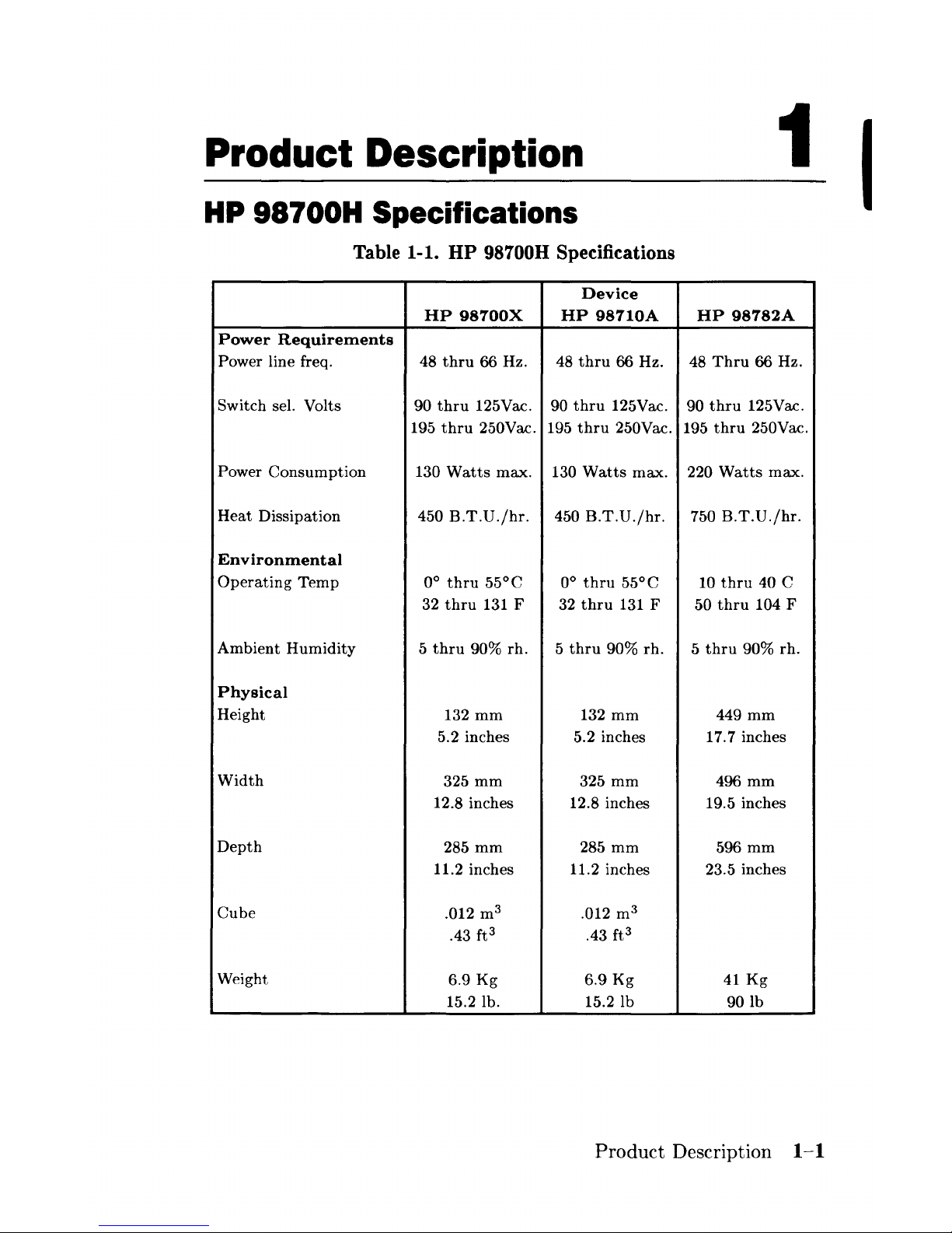
HP 98700H Specifications
Table 1-1.
HP
98700H Specifications
Device
HP
98700X
HP
98710A
HP
98782A
Power
Requirements
Power line freq.
48
thru
66 Hz. 48
thru
66 Hz. 48
Thru
66 Hz.
Switch sel. Volts
90
thru
125Vac. 90
thru
125Vac. 90
thru
125Vac.
195
thru
250Vac. 195
thru
250Vac.
195
thru
250Vac.
Power
Consumption
130
Watts
max.
130
Watts
max.
220
Watts
max.
Heat
Dissipation
450
B.T.D./hr.
450
B.T.D./hr.
750
B.T.D./hr.
Environmental
Operating
Temp
0°
thru
55°C 0°
thru
55°C 10
thru
40 C
32
thru
131 F 32
thru
131 F 50
thru
104 F
Ambient
Humidity
5
thru
90%
rho
5
thru
90%
rho
5
thru
90%
rho
Physical
Height
132
mm
132
mm
449mm
5.2 inches 5.2 inches 17.7 inches
Width
325
mm
325
mm
496mm
12.8 inches 12.8 inches 19.5 inches
Depth
285
mm
285
mm
596mm
11.2 inches
11.2 inches
23.5 inches
Cube
.012 m
3
.012 m
3
.43 ft
3
.43 ft
3
Weight
6.9
Kg
6.9
Kg
41
Kg
15.2 lb.
15.21b
90lb
Product
Description
1-1
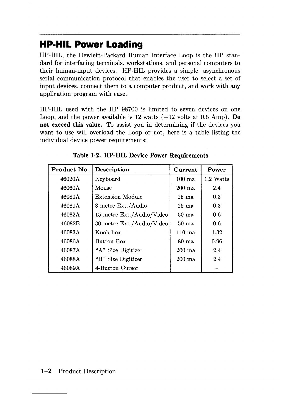
HP·HIL Power Loading
HP-HIL,
the
Hewlett-Packard
Human
Interface Loop
is
the
HP
stan-
dard
for interfacing terminals, workstations,
and
personal computers
to
their
human-input
devices. HP-HIL provides a simple, asynchronous
serial communication protocol
that
enables
the
user
to
select a set of
input
devices, connect
them
to
a computer
product,
and
work with any
application
program
with
ease.
HP-HIL used
with
the
HP
98700
is
limited to seven devices on one
Loop,
and
the
power available
is
12
watts
(+12
volts
at
0.5 Amp). Do
not
exceed this value. To assist you in determining if
the
devices you
want
to
use will overload
the
Loop or not, here is a table listing the
individual device power requirements:
Table 1-2.
HP-HIL
Device Power Requirements
Product
No.
Description
Current
Power
46020A
Keyboard
100 rna
1.2
Watts
46060A Mouse
200 rna
2.4
46080A
Extension
Module 25 rna 0.3
46081A
3
metre
Ext./
Audio
25
rna
0.3
46082A
15
metre
Ext./
Audio/Video
50 rna 0.6
46082B
30
metre
Ext./
Audio/Video
50 rna 0.6
46083A
Knob
box
110 rna 1.32
46086A
Button
Box 80 rna
0.96
46087A
"A" Size
Digitizer 200 rna
2.4
46088A
"B" Size
Digitizer 200 rna
2.4
46089A
4-Button
Cursor
-
-
1-2
Product
Description
As
stated
above the Loop
is
limited
to
seven devices.
Another
restriction
is
the
length of cable between each device. Maximum distance
is
2.4 me-
tres1 device
to
device1 with a
total
of
21
metres maximum. This does
not
include
the
15
metre and
30
metre extension options
that
are available.
Overloading the Loop will result in a blown fuse on
the
Loop interface
circuitry.
The
troubleshooting procedure
is
to
replace
the
assembly
that
contains
the
Loop interface circuitry
and
then1 before restoring power
to the system
1
refigure
the
power loading on
the
Loop.
If
the
loading
is
too highl
the
Loop will have
to
be unloaded by removing devices until
the power loading
is
in
the
proper
range.
Documentation
Documentation for the
HP
98700H
is
contained in four documents:
98700-90001
98700-90030
98700-90039
98782-90001
98782-90030
98782-90039
97089-90039
98680-90039
Installation Guide for
the
graphics display station.
Hardware Support Document for
the
graphics dis-
play station.
CE
Handbook Insert for
the
graphics display sta-
tion
..
Installation Guide for
the
monitor.
Hardware
Support
Document for
the
monitor.
CE
Handbook Insert for
the
monitor.
HP-UX
CE
Handbook1 Series 500.
HP-UX
CE
Handbook1 Series 200.
Other
documents
that
will be helpful are
the
installation
and
hardware
support
documents for
the
computer system
the
HP
98700H is a
part
of.
Product
Description
1-3

Notes
1-4
Product
Description
Environmental/Installation/
Preventive Maintenance
2
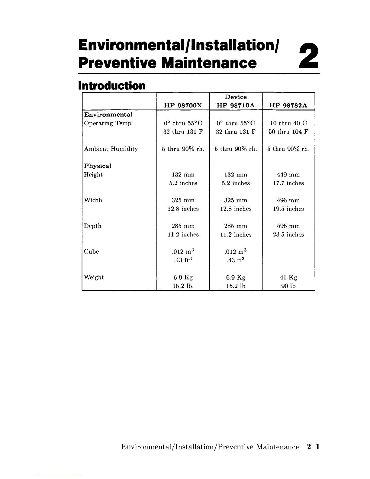
Introduction
Device
HP
98700X
HP
98710A
HP
98782A
Environmental
Operating
Temp
0°
thru
55°C
0°
thru
55°C
10
thru
40 C
32
thru
131 F 32
thru
131 F 50
thru
104 F
Ambient
Humidity
5
thru
90%
rho
5
thru
90%
rho
5
thru
90%
rho
Physical
Height
132
mm
132
mm
449
mm
5.2 inches
5.2 inches
17.7 inches
Width
325
mm
325
mm
496
mm
12.8 inches 12.8 inches 19.5 inches
Depth
28.5
mm
285
mm
596
mm
11.2 inches
11.2 inches
23.5 inches
Cube
.012 m
3
.012 m
3
.43
ft3
.43
ft3
Weight
6.9
Kg
6.9
Kg
41
Kg
15.2 lb.
15.21b
90lb
Environmental/Installation/Preventive
Maintenance
2-1
Site Preparation
Refer
to
the
HP
9000 Series 200/300/500 Site
Preparation
Document,
part
number
09000-90041,
to
assist you in preparing for
the
installation
of
the
HP
98700H Graphics Display Station. Refer
to
the
lists in
Chapter
1 for specific power
and
environmental requirements.
Cable Restrjctions
RGB
Cables
There
are
two styles of RGB cables
supported
with
the
display station:
• A single,
three
metre cable
with
three shielded conductors. Each
conductor
is
color coded for RG B and
terminated
with BN C conec-
tors
.
• A set of
three
co-ax cables
with
BNC connectors. One for each
color.
There
is
no real limitation on
the
length of
the
cables
other
than
loading. Due
to
this loading, the maximum
supported
length
is 30 metres. Two lengths are available from Hewlett-Packard,
15
metres
and
30 metres.
Series
300110
Interconnect Cable
The
Series 300 interconnect cable connects
the
Model 310/320
to
the
HP
98700.
The
cable connector key projects outward near the
top
from
each end of
the
connector shell. Ensure
that
this
is
UP
when connecting
to
the
I/O
card
or
the
HP
98700.
Series
500
Display Station Buffer Interconnect Cable
The
Display
Station
Buffer Interconnect cable
(p/n
HP
98700-61583)
connects
the
Model 550 to
the
HP
98700.The interconnect cable is in-
stalled by
an
HP
Customer Engineer or
HP
trained
engineer.
The
HP
98700 end of
the
cable
is
installed
with
the
keys on
the
connector
in
the
top
position.
The
cabinet connector has two slots on
the
sides of
its shell
to
accept
the
keys on
the
cable connector.
2-2
Environmental/Installation/Preventive
Maintenance
HP·HIL Cables
HP-HIL
is
limited
to
seven devices on one loop,
and
the
power available
is
12
watts
(+12
volts
at
1 Amp). Do
not
exceed this value.
Another
restriction
is
the
length of cable between each device. Maximum distance
is
2.4 metres, device
to
device,
with a total
of 16.8 metres maximum.
This does not include
the
15
metre
and
30
metre
extension options
that
are available.
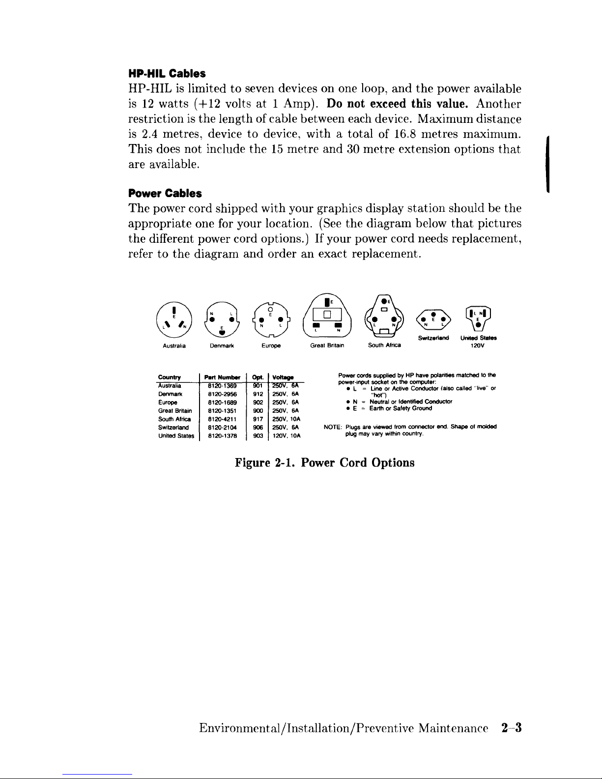
Power Cables
The
power cord shipped
with
your graphics display
station
should be
the
appropriate
one for your location. (See
the
diagram below
that
pictures
the
different power cord options.)
If
your power cord needs replacement,
refer
to
the
diagram
and
order
an
exact replacement.
@
&§J
~
~
Q
G3
[QJ
~
• •
~
~
•
N l
~
~
N l
Switzerland United States
Australia
Denmark
Europe
Great Britain
South Africa
120V
Country
Part Number
Power cords supplied
by
HP
have polarities matched to the
ustralia 8120-1369
power-input socket
on
the
computer:
• L
= Line
or
Active Conductor (also called "live" or
Denmark
8120-2956
912 250V,
6A
"hot")
Europe 8120-1689
902
250V, 6A
• N = Neutral or Identified Conductor
Great Britain 8120-1351
900
250V, 6A
• E = Earth
or
Safety Ground
South Africa 8120-4211
917
250V, lOA
Switzerland 8120-2104
906
250V,
SA
NOTE:
Plugs
are viewed from connector and. Shape of molded
United States 8120-1378
903
12OV,
lOA
plug may vary within country.
Figure 2-1. Power
Cord
Options
Environmental/Installation/Preventive
Maintenance
2-3
I
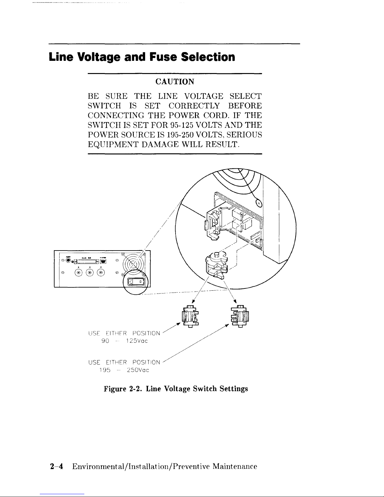
Line Voltage and Fuse Selection
CAUTION
BE
SURE
THE
LINE VOLTAGE
SELECT
SWITCH
IS
SET
CORRECTLY
BEFORE
CONNECTING
THE
POWER
CORD.
IF
THE
SWITCH
IS
SET
FOR
95-125 VOLTS AND
THE
POWER
SOURCE IS 195-250 VOLTS. SERIOUS
EQUIPMENT
DAMAGE WILL RESULT.
0io~~
0
Q) ®®® 0
USE
195
-
250Vac
Figure 2-2. Line Voltage Switch Settings
2-4
Environmental/Installation/Preventive
Maintenance

WARNING
BEFORE
REMOVING
THE
FUSE HOLDER
CAP
TO
CHECK OR CHANGE
THE
FUSE,
BE SURE THAT ALL
POWER
IS
DISCON-
NECTED FROM
THE
GRAPHICS DISPLAY
STATION.
CAUTION
REPLACEMENT FUSES MUST BE RATED
FOR
250
VOLTS, AND MUST
NOT
EXCEED
THE
CURRENT RATING INDICATED ON
THE
REAR PANEL. OTHERWISE EQUIP-
MENT DAMAGE
OR
FIRE
WILL RESULT.
Environmental/Installation/Preventive
:Maintenance
2-5
Installation
The
HP
98700H Graphics Display
Station
may
be
installed as
part
of a
new
computer
system,
or
it
may
be
installed as
an
enhancement
to
an
existing system.
In
either case
the
computer
must
be installed
and
its
performance verified first. Follow
the
instructions in
the
computers In-
stallation Guide,
and
accomplish
the
self tests.
When
the
computer
and
its
required memory
and
peripherals are known
to
be
working properly,
then
proceed
with
the
display
station
installation.
Required Tools
Installation
of
the
display
station
does
not
require special tools. How-
ever, here is a list of tools
that
will
be
useful:
•
Pozidrive@
screwdriver,
number
1,
3 inches long.
•
Pozidrive@
screwdriver,
number
2,
4 inches long.
•
Antistatic
Workstation
HP
part
number
9300-0933.
2-6
Environmental/Installation/Preventive
Maintenance
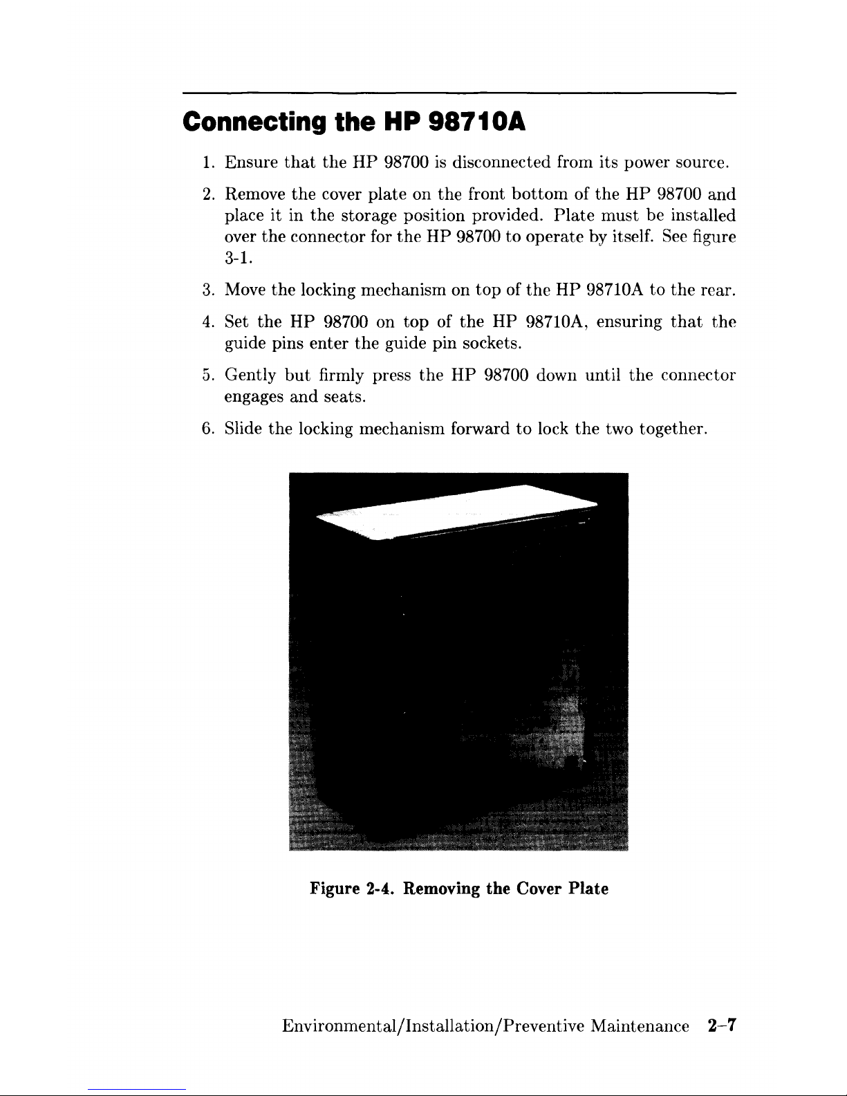
Connecting the HP 98710A
1.
Ensure
that
the
HP
98700
is
disconnected from its power source.
2.
Remove
the
cover plate on the front
bottom
of
the
HP
98700
and
place it in
the
storage position provided.
Plate
must
be installed
over
the
connector for
the
HP
98700 to operate by itself. See figure
3-1.
3.
Move
the
locking mechanism on
top
of
the
HP
98710A
to
the
rear.
4.
Set
the
HP
98700 on
top
of
the
HP
98710A, ensuring
that
the
guide pins enter
the
guide pin sockets.
5.
Gently
but
firmly press
the
HP
98700 down until
the
connector
engages
and
seats.
6.
Slide
the
locking mechanism forward
to
lock
the
two together.
Figure 2-4. Removing the Cover Plate
Environmental/Installation/Preventive Maintenance
2-7
-=
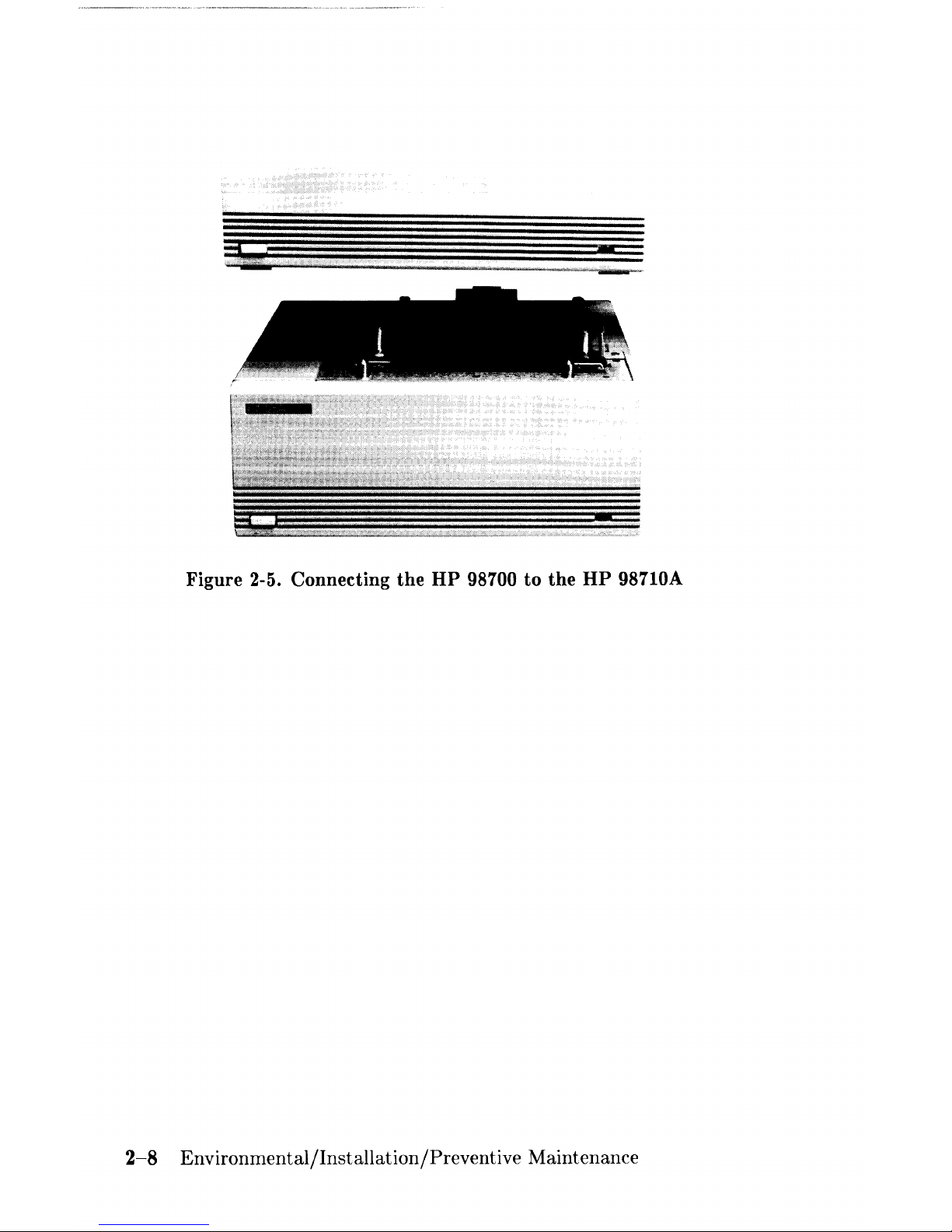
Figure 2-5. Connecting
the
HP
98700
to
the
HP
98710A
2-8
Environmental/Installation/Preventive
Maintenance
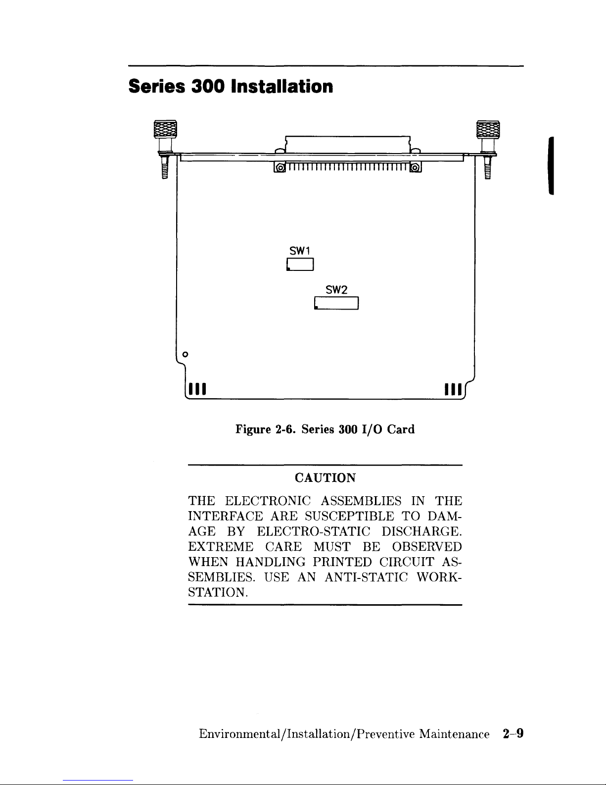
Series 300 Installation
o
SW1
CJ
SW2
L
III
III
Figure 2-6. Series 300
I/O
Card
CAUTION
THE
ELECTRONIC ASSEMBLIES IN
THE
INTERFACE
ARE
SUSCEPTIBLE
TO
DAM-
AGE
BY ELECTRO-STATIC DISCHARGE.
EXTREME
CARE MUST BE OBSERVED
WHEN HANDLING
PRINTED
CIRCUIT
AS-
SEMBLIES. USE AN ANTI-STATIC WORK-
STATION.
Environmental/Installation/Preventive Maintenance
2-9
I

Carefully remove the
HP
98287 A
I/O
card from its protective bag.
There
are two switches on
the
I/O
card
used to set
the
locations
that
the
HP
Human
Interface
LOOP
(HP-HIL) and
the
HP
98700 will respond
to. Switch 1 is a
five
section switch
that
sets
the
select code of the
HP
98700 HP-HIL. Switch 2
is
an
eight section switch
that
sets
the
location
of
the
HP
98700 control space
and
frame buffer. For switch location see
Figure 3-5.
Pascal
and
BASIC operating systems will
not
support
HP-HIL through
the
HP
98700H. HP-HIL
must
be
installed through
the
HP-HIL connec-
tor
in
the
rear
panel of
the
Series 300 computer. Refer
to
the
Installation
Guide
for your computer for details.
1.
Set
the
switches as desired. See Figure 2-7.
LSB
HP-HIL
SELECT CODE
SWITCHES
FACTORY
01
0
SETTING~
1
02
FB ADDRESS
0
$200
000
1
$300
000
0
$800
000
$900
000
Figure 2-7. Setting the Switches
2-10
Environmental/Installation/Preventive
Maintenance
2.
Install
the
I/O
card in any DIO slot in
the
backplane of
the
com-
puter
or any slot in
the
epander. Ensure
that
it is fully seated.
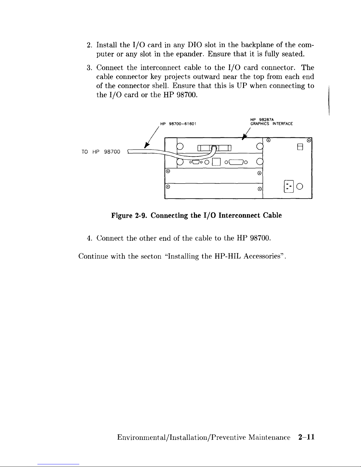
3.
Connect
the
interconnect cable
to
the
I/O
card
connector.
The
cable connector key projects outward
near
the
top
from each end
of
the
connector shell. Ensure
that
this is
UP
when connecting
to
the
I/O
card or
the
HP
98700.
HP
98287A
HP
98700-61601
GRAPHICS
INTERFACE
I
0
El
TO
HP
98700
0
0
0
0
[JO
Figure 2-9. Connecting the
I/O
Interconnect Cable
4.
Connect
the
other
end of
the
cable to
the
HP
98700.
Continue with
the
seeton "'Installing
the
HP-HIL Accessories".
Environmental/Installation/Preventive Maintenance
2-11
 Loading...