

HP
9800
Series
Computers
98780
CE
Handbook
Part No. 98780-90039
E 1283
Requires Binder No.
9282-0683
Fli;-
HEWLETT
~~
PACKARD
Printed in U.S.A
Second Edition, December 1983
98780
CE Handbook
ct;
Copyright 1982, 1983, Hewlett-Packard Company
This document contains proprietary information which is protected by copyright
All
rights are reserved,
No
part of this
document may be photocopied, reproduced or translated to another language without the prior written consent of
Hewlett-Packard
Company, The information contained
in
this document is subject to change without notice
Restricted Rights Legend
Use,
duplication,
or
disclosure by the Government is subject to reslrictions
as
set forth
in
paragraph (b)(3)(B) of the
Rights in Technical Data and Software clause in DAR
7-104,9(a)
Hewlett-Packard
Company
3404 East Harmony Road, Fort Collins, Colorado 80525
(hdpter
1
4H7HO
Prndll(1
Intonndtlon
l
hdpt('r
"-
n.,-;/-'o
I
1I\l1"'IIIWllldi
III~ldtidll"'1
t
\1
l
hdpll'l
\
"K7KO (
Jlillqdldtl,,,,
(hdptl>l
I
Q"7kO
I"
Id""~h(")l'l1c;
l
alt1ph~1
.J
'is,
SO
I
lld'lIH
,~II'
~
(
hdjll(,l
(,
9H7HO
,\dJlIstIlWllh
(
hapll'r
7
YH7HO
PI'T1plH'r<tI~
l
hdpter
H
YH7S0
Rl'pld(
Pllwnt
Pdrts
(
hdptpr
9
woso
Dld~1r<1IlI;o,
ChdPll'1
10
YHiHO
Hetl'H'tl(
l'
(
h.'ll't"y
11
9H7HO
Sl:'n
Ill'
Nolt's
ii
Printing History
New
editions
of
this
manual
will incorporate all material
updated
since the previous edition.
Update
packages
may
be
issued
between
editions
and
contain replacement
and
additional pages to
be
merged
into
the
manual
by
the user. Each
updated
page will
be
indicated
by
a revision date
at
the
bottom
of
the
page. A vertical
bar
in
the margin indicates the changes
on
each page.
Note
that pages
which are rearranged
due
to changes
on
a previous page are
not
considered revised.
The
manual
printing
date
and
part
number
indicate its current edition.
The
printing date changes
when a new
edition
is
printed.
(Minor
corrections
and
updates which are incorporated
at
reprint
do
not
cause the
date
to change. )
The
manual
part
number
changes
when
extensive technical changes
are incorporated.
October
1982
... First Edition
December
1983
...
Second
Edition.
Updated
pages: ii,
1-2,
8-3,
9-1.
Warranty
Statement
Hewlett-Packard products are warranted against defects
in
materials and workmanship.
For
Hewlett-Packard Fort Collins
Systems Division products sold
in
the
U.SA
and Canada, this warranty applies for ninety (90) days from the date of delivery.'
Hewlett-Packard will, at its option, repair or replace equipment which proves to be defective during the warranty period. This
warranty includes labor, parts, and surface travel costs,
if
any. Equipment returned to Hewlett-Packard for repair must be
shipped
freight prepaid. Repairs necessitated by misuse of the equipment. or by hardware, software, or interfacing not
provided by Hewlett-Packard are not covered by this warranty
HP
warrants that its software and firmware designated by
HP
for use with a
CPU
will execute its programming instructions
when properly
installed on that
CPU.
HP
does not warrant that the operation
of
the CPU. software. or firmware will be uninter-
rupted or error free
HEWLETI-PACKARD MAKES NO WARRANTY
OF
ANY KIND
WITH
REGARD
TO
THIS MATERIAL. INCLUDING. BUT NOT
LIMITED
TO,
THE
IMPLIED WARRANTIES
OF
MERCHANTABILITY AND
FITNESS
FOR
A PARTICULAR PURPOSE Hewlett-
Packard
shall not
be
liable for errors contained herein or for incidental or consequential damages
in
connection with the
furnishing, performance or use of this material
98780-90039.
rev
1283
98780
Product
Information 1-1
Chapter 1
Product Information
98780A Specifications
Environmental
Range
Operating Temperature:
Storage Temperature:
Ambient Humidity:
Size/Weight
Height:
Width:
Depth:
Net Weight:
Display Features
Cathode Ray Tube:
Scan:
Refresh Rate:
Vertical
Scan
Rate:
Alphanumeric Display
Alpha Raster Size:
Screen Capacity:
Character Font:
Character Size:
Standard
Character Set:
Additional Character Sets:
Cursor:
Highlighting:
Graphics Display
Graphics Raster Size:
Matrix Size:
Graphics Memory:
Graphics Cursor:
Resolution:
Vector Drawing Speed:
+ 5°C to + 40°C ambient
-
40°C to + 65°C
<80%
26.5
cm
41cm
38
cm
14
kg
30.5
cm (12 inch) diagonal
Non-interlaced raster scan
60
Hz
60
Hz
236
mm x 149 mm (720 dots x
455
dots)
2400
characters (30 lines of
80
characters)
7 dot x 9 dot
in
a 9 x 15 matrix
2.3 mm wide x
3.0
mm high
(7
x 9 character)
128 ASCII characters
European, Katakana
Blinking underline,
bliflking back arrow
Inverse video, blinking, underline
184
mm x 149 mm (560 dots x
455
dots)
560
dots x
455
dots
16
k-words of read/write memory
Full-screen
and
small crosshair, blinking underline
Dots are spaced .33 mm center to center
254
metres
per
second
I
1-2 98780 Product Information
Options and Configurations
The
98780A
is available as either a part of the
98458
#2XX
or
as part of the 98404A Upgrade
Kit.
(Upgrades 9845B to High Performance CRT) 98404A
98405A
98775A
Upgrade Kit
Upgrade Kit
Light
Pen
(Upgrades 9845B to High Performance CRT and
fast
processor)
(Also available
as
9845B #775 or 98404A #775)
Available character sets are:
9845B ASCII/European (Also 98404A standard)
9845B
#840
Katakana (Also 98404A #041)
Related Documentation
98780-90030 Service Manual
09845-93050 Monochromatic Graphics Programming Manual
09845-92005 Owner's
and
System Exerciser Manual
09845-90039 98780
CE
Handbook
Product Support Package
The
98780A
requires
no
special tools to service other than those which are provided for
servicing
the
98458.
Safety
LETHAL VOLTAGES
ARE
PRESENT INSIDE THE 98780A.
RE-
FER
TO THE GENERAL SAFETY GUIDELINES IN THE 98780A
SERVICE MANUAL.
Modifications
for
9000 Series 500 Model 20
The
98780A
display unit
is
used with the
9000
computers
and
must
be
modified by the addition
of a printed circuit board. This board
is
installed inside its own housing that
is
attached to the
under
side
of
the display housing. This board forms the interface between the 98780A
and
the
9000
computer. The service information
is
contained
in
the Service Manual for the
9000
computers. (HP part
number
09020-90038)
98780-90039. rev: 12/83
98780 Environmental/Installation/PM 2-1
Chapter 2
Environmental/Installation!
Preventive Maintenance
Installation
The display assembly
fits
into place over the mainframe support legs.
I CAUTION I
THE 98780A RELIES ON THE MAINFRAME TOP COVER FOR
WEIGHT SUPPORT. THE MAINFRAME TOP COVER MUST BE
INSTALLED BEFORE INSTALLING THE
98780A.
Pull out the locking rods (one
on
the back of each support leg)
and
place the 98780A over the
mainframe support legs as shown
in
Figure 1-1. Push
in
on the locking rods to lock the 98780A
to the mainframe.
98780A Installation
Locking rod
pulled out
I

2-2
98780
Environmental/Installation/PM
Base
Configuration
98780
Configuration 3-1
Chapter 3
Configuration
The following assemblies must be installed
in
the 9845B base to support the 98780A. (These
parts are included
in
the 98404A Upgrade
Kit.)
98780-65501
1818-1591
and
1818-1592
98770-66534
Enhanced Graphics
ROM
Mainframe
ROM
for Enhanced Graphics
ROM
Mainframe
ROM
for Enhanced Graphics
ROM
Alpha Control Assembly (Replaces
09845-66503
in
base.)
Refer to the
9845B
Base CE
Handbook
Chapter
for the locations of these parts.
Interfacing
The 98780A interfaces to the
9845B
base via the Alpha Control Assembly (98770-66534)
and
the Graphics Interface Assembly (09845-66504). Alpha information
is
stored
in
block 0 read-
write memory,
and
is
refreshed to the display via the
IDA
bus. Graphics information
is
transfer-
red via the
I/O
bus
to the display, where
it
is
interpreted
and
entered into the display memory.
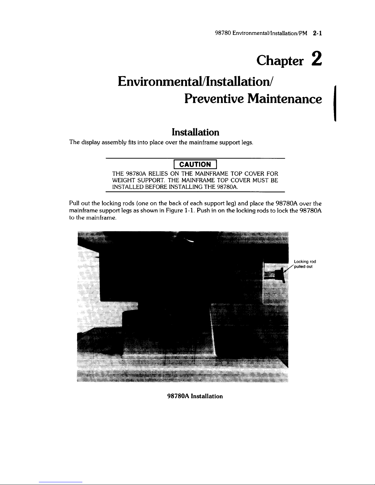
Status Word
The Status Word may
be
obtained by executing the following instructions:
STATUS 13;A
DISPA
The result
is
a decimal integer which may be converted to binary
and
interpreted as shown
below.
Bit
Bit Description
13 Graphics status
11,9 Identification bits
7 Interrupt enable
6
DMA
enable
3 Option service request
2 Graphics service request
1 Softkey service request
o Light pen service request
I

3-2
98780
Configuration
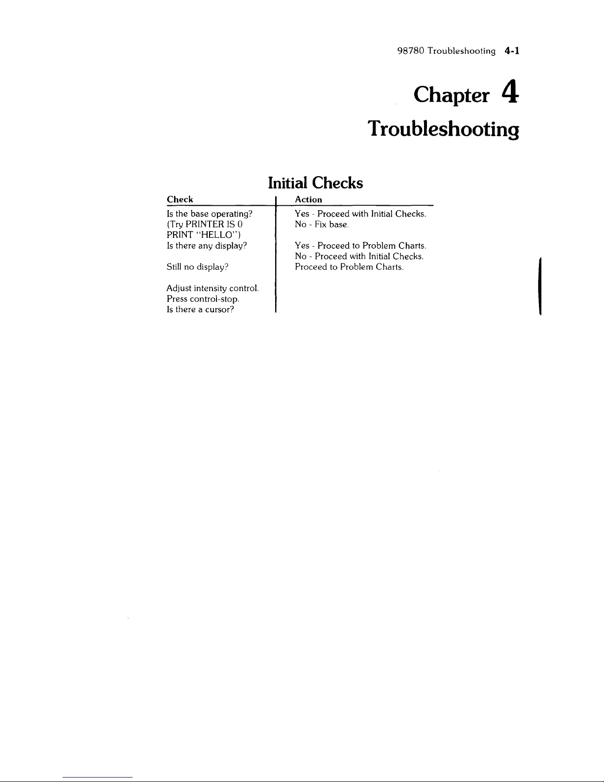
Check
Is
the
base
operating?
(Try
PRINTER
IS
0
PRINT
"HELLO")
Is
there
any
display?
Still no display?
Adjust intensity control.
Press control-stop.
Is
there a cursor?
Initial Checks
Action
98780
Troubleshooting
4-1
Chapter 4
Troubleshooting
Yes - Proceed with Initial Checks.
No -
Fix
base.
Yes -
Proceed to Problem Charts.
No -
Proceed with Initial Checks.
Proceed to Problem Charts.
4-2
98780
Troubleshooting
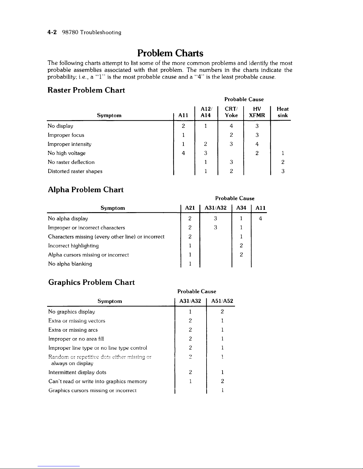
Problem
Charts
The
following charts attempt to list
some
of the more common problems
and
identify the most
probable assemblies associated with that problem. The numbers
in
the charts indicate the
probability; i.e., a
"I"
is
the most probable cause
and a "4"
is
the least probable cause.
Raster Problem Chart
No display
Improper focus
Improper intensity
No high voltage
Symptom
No raster deflection
Distorted raster
shapes
Alpha Problem Chart
Symptom
No
alpha
display
Improper or incorrect characters
Characters missing (every
other
line)
or
incorrect
Incorrect highlighting
Alpha cursors missing
or
incorrect
No
alpha
blanking
Graphics Problem Chart
Symptom
No graphics display
Extra or missing vectors
Extra or missing arcs
Improper or no
area
fill
Improper line type
or
no line type control
Random
or
repetitive
dC)ts
either
!Tl!ss!ng
or
always
on
display
Intermittent display dots
Can't
read
or write into graphics memory
Graphics cursors missing or incorrect
Probable
Cause
A12/ CRT/
HV
All
A14 Yoke XFMR
2
4
A21
2
2
2
4
2
2 3
3
3
2
Probable
Cause
A3liA32
3
3
A34
2
2
Probable
Cause
A3liA32
2
2
2
2
2
2
A5liA52
2
1
2
3
3
4
2
All
4
Heat
sink
1
2
3
98780
Troubleshooting
4-3
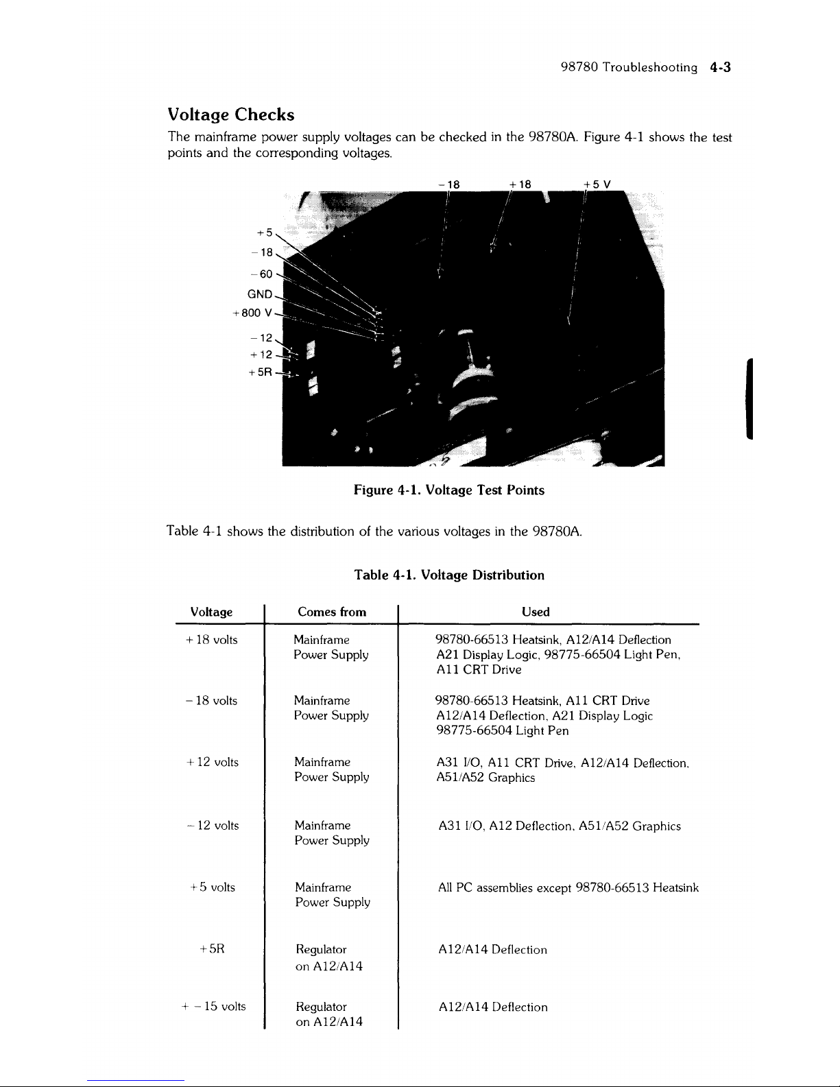
Voltage Checks
The mainframe power supply voltages can be checked
in
the 98780A. Figure 4-1 shows the test
points and the corresponding voltages.
+5
-18
-60
GND
+800 V
-12
+12
+5R
-18
+18
+5
V
Figure 4-1. Voltage Test Points
Table 4-1 shows the distribution of the various voltages
in
the 98780A.
Table 4-1. Voltage Distribution
Voltage Comes from
Used
+ 18 volts Mainframe 98780-66513 Heatsink, A12/A14 Deflection
Power Supply A21 Display Logic.
98775-66504
light
Pen,
All
CRT Drive
-18
volts
Mainframe 98780-66513 Heatsink,
All
CRT Drive
Power Supply
A12/A14 Deflection, A21 Display Logic
98775-66504
light
Pen
+ 12 volts
Mainframe
A31
I/O,
All
CRT Drive, A12/A14 Deflection,
Power Supply
A511A52
Graphics
-12
volts
Mainframe
A31 I/O, A12 Deflection, A51/A52 Graphics
Power Supply
+5
volts Mainframe
All
PC assemblies except 98780-66513 Heatsink
Power Supply
+5R
Regulator A12/A14 Deflection
on A12/A14
+
-15
volts
Regulator
A12/A14 Deflection
on A121A14
I
 Loading...