

HP
9800
Computers
98770
CE
Handbook
Part
No.
98770-90039
E1083
Requires Binder
No.
9282-0683
Flin-
HEWLETT
~~
PACKARD
Printed
in
[J
SA
Second Edition, October 1983
98770
CE
Handbook
f:
Copyright t 982, 1983, Hewle1t-Packard Company
This documen1 contains proprietary information which is protected by copyright.
All rights are reserved. No part of this
document may be photocopied, reproduced
or
translated to another language without the prior
wri1ten
consent of
Hewle1t-Packard Company. The information contained in this document is subject to change without notice
Restricted Rights Legend
Use, duplication, or disclosure by the Government is subject to restrictions as set forth
in
paragraph (b)(3)(B) of the
Rights
in
Technical Data and Software clause
in
DAR 7-104.9(a)
Hewlett-Packard
Company
3404 East Harmony Road, Fort Collins, Colorado 80525
(
hilplpr
1
98770
Product
Informdllllll
(
hilptpr
l
')'611U
LIIUHillllH'lltdllllstdlldtlOII
1';\1
(
hdpl"1
,~
Q",77()
(
IH11Jq11ldlH1l1
( h,'!'1<'r I
')S770 1
}(,1I1Jl,
~l)(H)tlll~
( IIdpl!'1 1
q~/ffl
I),
H",,,
...
Tl,
( hil(lt!'f h
()8770
\dJlI~tlll!'llh
( h,'1)((
17
'1'6770
i'l'lIph"r,lb
Chdplel
S
l}S770
Hepldl
PIII('111
Prlft<,
( hrlptPI 9
98770
Dld~lfdm.,
Chdptl'f
10
IJI'!770
Hl'tefPIH
P
(
In!", 1 11
98770
~'Wn
I(
P Notl''>
Ii
Printing History
New
editions of this manual will incorporate all material updated
since
the previous edition. Update
packages
may
be issued between editions and contain replacement and additional pages to be
merged into the manual by the user. Each updated page will be indicated by a revision date at the
bottom
of
the page. A vertical bar in the margin indicates the changes on each page.
Note
that pages
which are rearranged due to changes on a previous page are not considered revised.
The
manual printing date and part number indicate
its
current edition.
The
printing date changes
when a
new
edition
is
printed. (Minor corrections and updates which are incorporated at reprint do
not cause the date to change.)
The
manual part number changes when extensive technical changes
are incorporated.
First Edition ...
October
1982
Second Edition ... October
1983
Warranty
Statement
Hewlett-Packard products are warranted against defects
in
materials and workmanship. For Hewlett-Packard Fort Collins
Systems Division products sold
in
the
USA.
and Canada, this warranty applies
for
ninety (90) days from the date of delivery.'
Hewlett-Packard will.
at
its option, repair or replace equipment which proves to be defective during the warranty period. This
warranty includes labor, parts, and surface travel costs,
If
any Equipment returned to Hewlett-Packard for repair must be
shipped
freight prepaid. Repairs necessitated by misuse of the equipment. or by hardware, software, or interfacing not
provided by Hewlett-PacKara are not cove rea by
tnlS
warranty
HP
warrants that its software and firmware designated by
HP
for use with a
CPU
will execute its programming instructions
when properly installed on that
CPU.
HP
does not warrant that the operation of the CPU, software, or firmware will
be
uninter-
rupted or error free
HEWLETT-PACKARD
MAKES NO WARRANTY
OF
ANY
KIND
WITH
REGARD
TO
THIS
MATERIAL, INCLUDING, BUT NOT
LIMITED
TO,
THE IMPLIED WARRANTIES
OF
MERCHANTABILITY AND
FITNESS
FOR
A PARTICULAR
PURPOSE.
Hewlett-
Packard shall not
be
liable for errors contained herein or for InCidental or consequential damages
in
connection with the
furnishing, performance or use of this material
.
For
other
coun~nes
cor.tact
your
loca!
Sales
ard
SUPPo~
Office
to
de!er'T',re wana":y
terrT'S
98770
Product
Information 1-1
Chapter 1
Product Information
98770A Specifications
Environmental
Range
Operating Temperature:
Storage Temperature:
Ambient Humidity:
Size/Weight
Height:
Width:
Depth:
Net Weight:
Power Requirements
AC
Line Voltage:
Line Frequency:
Power Consumption
Display
Features
Cathode
Ray Tube:
Scan:
Refresh Rate:
Vertical
Scan
Rate:
Vertical Retrace Time:
Horizontal Scan Rate:
Horizontal Retrace Time:
Dot Scan Rate:
+ 5°C to + 40°C ambient
-
40°C to + 65°C
<80%
32
cm
46cm
45cm
29.45
kg
(65 lbs. )
110 volts ac (88 to 127 Vac)
220
volts ac (198 to
250
Vac)
48 to
66
Hz
(inclusive)
500
watts maximum (typical)
14
inch diagonal, delta-gun, black matrix
Non-interlaced raster scan
60
Hz
60
Hz
1.
03 milliseconds
29.1 kHz
10.2 microseconds
29.7984
MHz
I
1-2 98770 Product Information
Alphanumeric Display
Alpha Raster Size
Screen Capacity:
Character Font:
Character Size:
Character Colors:
Standard Character Set:
Additional Character Sets:
Cursor:
Highlighting:
Graphics Display
Graphics Raster Size:
Matrix Size:
Bits
Per
Point
Graphics Colors:
Graphics Cursor:
Resolution:
Vector Drawing Speed:
247 mm x
154
mm (720 dots x 455 dots)l
2400
characters (30 lines of
80
characters)2
7 dot x 9 dot
in
a 9 x 15 matrix
2.40 mm wide x 3.09 mm high
(7
x 9 character)
Black, white, red, green, blue, cyan, magenta, yellow
128 ASCII characters
European, Katakana
White blinking underline
Inverse video, blinking
and
underline
192 mm x
154
mm
(560 dots x 455 dots)
560
dots x 455 dots (254,800 addressable
pOints)
3 (one for each electron gun)
Black, white, red, green, blue, cyan, magenta, yellow
Full-screen
and
small crosshair, blinking underline
Dots are spaced .343 mm center to center
Approximately
10,000 inches per second
Modifications
for
9000
Series
500
Model 20
The 98770A display unit
is
used with the
9000
computers and must be modified by the addition
of a printed circuit board. This board
is
installed inside
its
own housing that
is
attached to the
underside of the display housing. This board forms the interface between the
98770A
and
the
9000
computer. The service information
is
contained
in
the Service Manual for the
9000
computers. (HP part number 09020-90038)
1
The
98770A
is
capable
of
displaying a 247 mm x 154 mm raster (720 dots x 455 dots). This raster
is
displayed when using the A13 test switch.
the self test fixture
and
the binary test cartridge. The 9845C
does
not use all of this area. During normal alpha operation. the alpha raster size
is
247 mm x 144 mm (720 dots x 420 dots).
2
The
9845C only uses 28 of the 30 lines.
98770 Product Information 1-3
Options and Configurations
The 98770A
is
available as either a part of the
9845C
or as part of the 98771A Upgrade
Kit.
Available accessories are:
98775A
98776A
98777A
Light
Pen
(Also available
as
9845C
#775
or 98771A
#775)
RGB Interface (Also available
as
9845C
#776
or 98771A
#776)
Camera Attachment
Available character sets are:
9845C ASCII/European
9845C
#840
Katakana
(Also 98771A standard)
(Also 98771A #772)
Related Documentation
98770-90032
Service Manual
09845-92051 Color Graphics
Programming Manual
09845-93005
Installation, Operating, and Test Manual
98770-90039
CE
Handbook
Section
Product Support Package
98770-66527
Test Fixture
98770-90031 Service Manual
09845-91031 Test Cartridge
(TBIN)
09845-92041 System Exerciser Cartridge (B/C)
09845-93005
Installation, Operation
and
Test Manual
Safety
LETHAL VOLTAGES
ARE
PRESENT INSIDE THE 98770A.
RE-
FER
TO THE 98770A SERVICE MANUAL
FOR
GENERAL SAFE-
TY GUIDELINES.
I

1-4
98770
Product
Information
98770 Environmental/Installation/PM 2-1
Chapter 2
Environmental/Installation/
Preventive Maintenance
Installation
The display assembly
fits
into place over the mainframe
support
legs. Early units did
not
have
locking hardware
on
the feet; current units do. If the hardware
is
there, lock
it.
I CAUTION I
THE 98770A RELIES ON THE MAINFRAME TOP COVER FOR
WEIGHT SUPPORT. THE MAINFRAME TOP COVER MUST
BE
INSTALLED BEFORE INSTALLING THE 98770A.
THE 98770A
IS
HEAVY (29.45 KILOGRAMS
OR
65 POUNDS).
TO
AVOID INJURY, ENLIST THE AID
OF
A SECOND PERSON
WHEN LIFTING THE 98770A. IF HELP
IS
NOT AVAILABLE, LIFT
FROM
REAR
OF
THE UNIT.
Initial Tum-On
I CAUTION I
THE 98770A HAS NO POWER SWITCH. IT
IS
SWITCHED ON
VIA A RELAY WHICH
IS
ACTIVATED WHEN THE 9845C MAIN-
FRAME
IS
SWITCHED
ON.
ALWAYS SWITCH THE 9845C POW-
ER
SWITCH TO THE OFF POSITION BEFORE CONNECTING
THE 98770A POWER CORD.
Before applying
power
to the computer, check the following items:
•
98770A
is
properly installed.
• Voltage selector switches set properly on both display
and
mainframe.
•
Proper
fuse installed
in
both display
and
mainframe.
•
Power
switch set to off.
•
Power
cords
connected
to both display
and
mainframe.
Switch the
power
switch on. After a 20-second (approximate) warmup time, the message
"9845
READY FOR USE"
will
appear
on
the CRT display, followed by the blinking cursor.
Adjust the intensity control located
beneath
the lower left corner of the CRT bezel for the
desired display intensity.
If the turn-on memory test
fails,
"PART OF MEMORY FAILED SELF-
TEST"
is
displayed.
I
2-2
98770
Environmental/Installation/PM
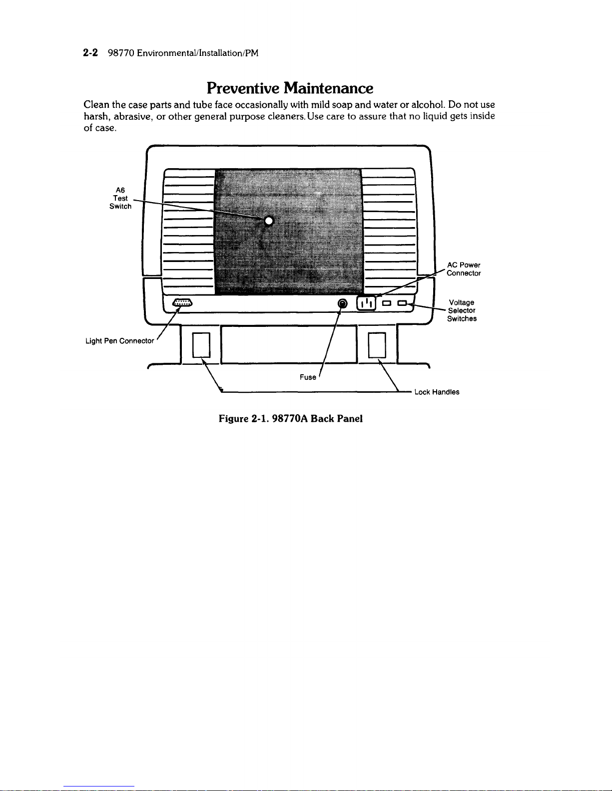
Preventive Maintenance
Clean the case parts
and
tube face occasionally with
mild
soap and water or alcohol. Do not use
harsh, abraSive,
or
other general purpose cleaners. Use care to assure that no liquid gets inside
of case.
A6
Test
Switch
Figure 2-1. 98770A Back Panel
AC Power
Connector
Voltage
Selector
Switches
98770 Configuration 3-1
Chapter 3
Configuration
Base Configuration
The following assemblies must be installed in the
9845C
base to support the 98770A. (These
parts are included in the 98771A Upgrade
Kit.)
98770-65501 Color graphics
ROM
1818-1208
Mainframe
ROM
1818-1209 Mainframe
ROM
98780-65501 Enhanced graphics ROM
1818-1591 Mainframe
ROM
or for either
98770-66534
Alpha control assembly
(replaces
09845-66503
in
Mainframe)
1818-1592 Mainframe
ROM
See
the
98458
CE Handbook
Chapter
for locations of these parts.
Interfacing
The 98770A interfaces to the
9845C
base via the Alpha Control Assembly (98770-66534)
and
the Graphics Interface Assembly (09845-66504). Alpha information
is
stored in block 0 read-
write memory,
and
is
refreshed to the display via the
IDA
bus. Graphics information
is
transfer-
red via the
I/O bus to the display, where
it
is
interpreted
and
entered into the display memory.
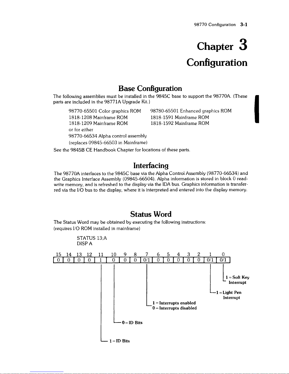
Status Word
The Status Word may be obtained by executing the following instructions:
(requires
I/O
ROM
installed
in
mainframe)
STATUS 13;A
DISPA
15
14
13
12
11
10101001
10 9
o 0
8 7 6 5
4 3
o I
011
I 0 0
o 0
1 = Interrupts enabled
o = Interrupts disabled
0=
ID
Bits
1
=ID
Bits
2 1 0
o I
Oil
I I
0[,
~
Soft
Key
Interrupt
1 = Light Pen
Interrupt
I

3-2
98770
Configuration
Check
[s
the base operating?
(Try PR[NTER
[S
0
PR[NT "HELLO")
[s
there any display?
Adjust intensity control.
Press control-stop
[s
there a cursor?
Check voltage select switches,
fuse,
and
line power.
Still no display?
98770
Troubleshooting
4-1
Chapter 4
Troubleshooting
Initial Checks
Action
Yes - Proceed with [nitial Checks.
No -
Fix
base.
Yes - Proceed to Raster Checks
No
- Proceed with [nitial Checks.
Yes - Proceed to Raster Checks.
No - Proceed with [nitial Checks.
Correct any fault.
Proceed to Inoperative Unit Checks.
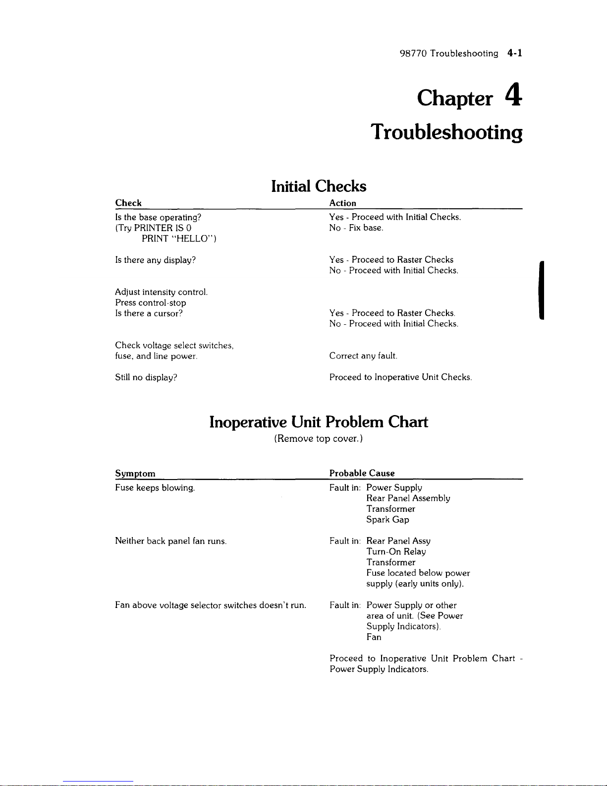
Inoperative Unit Problem Chart
(Remove
top
cover.)
Symptom
Fuse keeps blowing.
Neither back panel fan runs.
Fan
above
voltage selector switches
doesn't
run.
Probable
Cause
Fault
in:
Power Supply
Rear Panel Assembly
Transformer
Spark
Gap
Fault
in:
Rear Panel Assy
Turn-On Relay
Transformer
Fuse located below power
supply (early units only).
Fault
in:
Power Supply or other
area of unit. (See Power
Supply Indicators)
Fan
Proceed
to Inoperative Unit
Problem
Chart
-
Power Supply Indicators.
I
4-2 98770 Troubleshooting
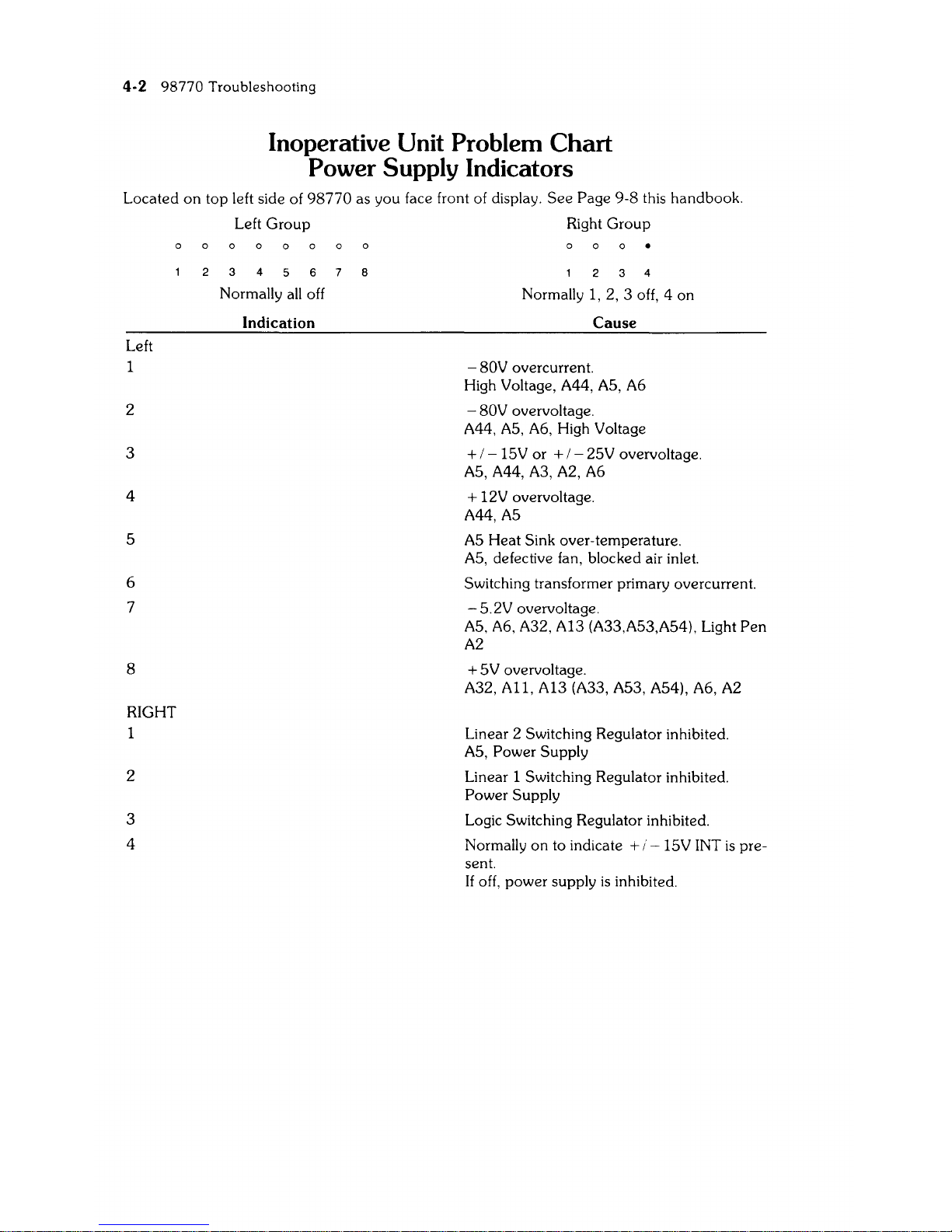
Inoperative Unit Problem Chart
Power Supply Indicators
Located
on
top left side of
98770
as you face front of display.
See
Page 9-8 this handbook.
Left
1
2
3
4
S
6
7
8
RIGHT
2
3
4
Left
Group
Right
Group
o
3 4
Normally
all
off
Indication
8
4
Normally 1, 2, 3 off, 4 on
Cause
- 80V overcurrent.
High Voltage, A44,
AS,
A6
-
80V overvoltage.
A44,
AS,
A6, High Voltage
+ / -
lSV
or + / - 2SV overvoltage.
AS,A44,A3,A2,A6
+ 12V overvoltage.
A44,AS
AS
Heat Sink over-temperature.
AS,
defective fan, blocked air inlet.
Switching transformer primary overcurrent.
- S.2V overvoltage.
AS,
A6,
A32, A13 (A33,AS3,AS4), Light
Pen
A2
+
SV
overvoltage.
A32, A11, A13 (A33, AS3, AS4), A6, A2
Linear 2 Switching Regulator inhibited.
AS,
Power Supply
Linear 1 Switching Regulator inhibited.
Power Supply
Logic Switching Regulator inhibited.
Normally
on
to indicate + i -
lSV
INT
is
pre-
sent.
If
off, power supply
is
inhibited.
Inoperative Unit
(Remove top cover)
I CAUTION I
98770
Troubleshooting
4-3
BEFORE REMOVING OR INSTALLING ANY tl,SSEMBL Y DISCONNECT
UNIT FROM POWER SOURCE
BY
REMOVING POW-
ER
CORD FROM BACK
OF
UNIT.
Note
As
viewed from rear of unit the left-hand fan
is
ac powered, the
right-hand fan
is
de powered.
Turn Unit
ON
If
no
display,
then
observe
Power
Supply Indicators.
See
page
4-2.
Observe the fans.
If
the ac fan (left-hand)
is
not turning, check:
a.
Fuse
b.
Power
source (wall connector, power cord, etc.)
c.
Computer
(use the turn-on fixture)
d.
Primary wiring
Note
If the ac fan starts turning as
soon
as the
power
cord
is
connected.
the
power-on
relay controlling
it
may
be
stuck closed.
If the ac fan
is
turning
but
the dc fan (right-hand)
is
not, check:
1.
Number
4 LED
in
the
right indicator group. If
lit
(brite),
power
supply
is
functional. Skip
to
Step
2.
2.
If
off (dark),
Power
supply
is
not
powered
or
inoperative. Replace
power
supply
and
AS
assembly
and
do
this section again. (see
AS
and
power
supply
procedure
See
Page
4-S. )
Check
Which
LED's Are Lit
The following list
is
for Left indicator group of LED's unless otherwise stated.
LED
#1
Lit
-
SO
Volt supply overcurrent.
1.
Unplug
power
cord.
2. Disconnect high voltage assembly.
3.
Plug
in
and
turn
on
(no display
will
be visible).
a.
All
LED's dark, unplug
power
cord
and
replace H.V. assembly.
b.
LED
#1
still ON, unplug
and
remove
A6 board.
4.
Plug
in
and
turn on.
a.
All
LED's dark, unplug
power
cord
and
replace A6 board.
b.
If
LED
#1
still
lit.
go to minimum configuration tests
See
Page
4-S.
LED
#2
Lit
-
SO
Volt supply overvoltage.
1.
Unplug
power
cord
2.
Replace
AS
and
Power
supply.
(See
AS
and
Power
Supply
procedure
See
Page
4-S.)
3.
Plug
in
and
turn ON. (no display
will
be visible). If LED
#2
still
lit,
go to minimum
configuration tests
See
Page
4-S.
4-4 98770 Troubleshooting
LED
#3
Lit
±
IS
or
± 2S Volt
Supply
overvoltage.
1.
Unplug
power
cord.
2. Do
AS
and
Power
Supply
procedure
See
Page
4-8.
3.
Plug in
and
turn ON.
If
LED
#3
still
lit.
go to minimum configuration tests.
LED
#4
Lit
+
12
Volt
Supply
overvoltage.
1.
Unplug
power
cord.
2. Do
AS
and
power
supply
procedure
See
Page
4-8.
3.
Plug in
and
turn ON.
If
LED
#4
still
lit,
go to minimum configuration tests.
LED
#5
Lit
AS
heatsink
temperature
higher
than
100°
C.
1.
Check
air flow
of
internal fan (near bottom of heatsink) by holding
hand
above
AS
heat
sink.
2. No air flow. Unplug
power
cord.
3.
Remove
AS
and
try to rotate fan by hand.
a.
If
frozen
(will
not
rotate), replace fan.
b.
If
it
spins, disconnect the fan
and
check the voltage at the
connector
(2S Vdc).
Check
the
wiring to fan.
See
Page
9-3, 9-4,
9-S.
4. Do
AS
and
power
supply
procedure
See
Page 4-8.
S.
Plug in
and
turn ON.
If
LED
#S
still
lit,
go to minimum configuration tests.
LED
#6
Lit
Switching transformer primary overcurrent.
1.
Unplug
power
cord.
2. Replace
power
supply.
LED
#7
Lit
- S.2 supply overvoltage.
1.
Do
AS
and
power
supply procedure.
See
Page
4-8.
2.
Go
to minimum configuration tests, Page 4-S.
LED
#8
Lit
+ S Volt supply overvoltage.
1.
Replace
AS
board.
See
Page
4-8.
2.
Go
to minimum configuration tests.
See
Page
4-S.
Right Indicator Group
LED
#1
or
#2
or
#3
lit.
1.
Replace
Power
Supply.
a.
Do
AS
and
Power
Supply
procedure
See
Page
4-8.

98770 Troubleshooting 4-5
Minimum Configuration Tests
Use this procedure when the unit has an inoperative power supply or
will
not indicate the
presence of
± 15 Volts dc, or when primary wiring defects are suspected.
Minimum Configuration
Minimum configuration consists
of:
1.
Base assembly
and
mother board.
2.
Power supply
and
primary wiring.
3.
A5
board
(98770-66505).
4.
A44
board
(98770-66544).
5.
Turn on fixture or installed
on
Computer.
I CAUTION
DO
NOT
RUN UNIT IN MINIMUM CONFIGURATION FOR MORE
THAN
30 SECONDS AT A TIME. (MINIMUM PLUS A33 BOARD
CAN
BE
RUN INDEFINITELY)
To achieve minimum configuration, remove:
1.
The
A6
board
(98770-66506).
2.
The
All
board
(98770-66511).
3.
The A32
board
(98770-66532).
4.
The A33
board
(98770-66533/13/53/54).
5. The
98775-66501166504
board
if
present.
6. Three
503
boards
(98770-66503). Note the order of removal to avoid reconvergence.
7.
The
502
board
(98770-66502).
8. Remove the CRT assembly (be careful to disconnect
YOKE wiring
under
the CRT).
Preliminary Procedure
Plug unit into power source
and
listen to
"wake-up"
sounds as you turn unit
on
(ignore LEOS
when base
is
turned OFF):
a.
Relay closure click
in
top.
b.
All
fans turning.
c.
Steady
beep
from base
is
normal. There
is
no handshake.
d.
Watch LED's.
If
any LED
lit,
do
A5
and
Power Supply Procedure.
#4
LED
in
right
indicator group normally
lit
(brite).
e.
Retest.
If
LED still
lit.
replace A44
or
Mother
board
(Rare).
f.
Unplug unit.
Unit must pass the minimum configuration tests before proceeding to next page.
I
4-6 98770 Troubleshooting
Unit Rebuild
Do minimum configuration tests before proceeding with unit rebuild.
I CAUTION I
BEFORE REMOVING
OR
INSTALLING ANY ASSEMBLY DISCONNECT UNIT FROM POWER SOURCE BY REMOVING POWER
CORD FROM BACK
OF
UNIT.
1.
Install
the
A33 Board
and
test run.
a.
Pass -
Power
supply
comes
up.
#4
LED
lit.
all
other
LED's dark.
no
beep
from
mainframe.
b.
Fail -
If
any
LED
lit,
except
#4,
replace A33 board.
c.
Test run (repeat
Step
1).
2. Install the CRT
and
Yoke assembly. Make
all
connections to Yoke.
but
do
not
connect
high voltage.
a.
Pass -
Power
supply
comes
up,
#4
LED
lit,
all
other
LED's dark.
b.
Fail-
If
any
LED
lit,
except
#4,
replace CRT
and
Yoke assembly.
c.
Test run (repeat
Step
2).
3.
Connect
high voltage.
a.
Pass -Power
supply
comes
up.
#4
LED
lit.
other
LED's dark. listen for HV crackle.
b.
Fail - If any LED
lit.
except
#4.
replace high voltage assembly.
c. Test run (repeat
Step
3).
4. Install the A6 assembly. Install
all
mounting screws.
a.
Pass - Power supply up. display visible but no horizontal sync. (Retrace lines visible,
convergence close but colors separated. no alpha, no graphics).
#4
LED
lit,
other LED's
dark.
b.
Fail - Replace A6 assembly
c.
Test run (repeat
Step
4).
5.
Connect
Video cable from A33 to A6. Assure that the cable keys mate correctly.
a.
Pass
- Power supply up. Alpha display. convergence close but colors separated.
no
retrace lines.
(If
retrace visible. recheck cable
for
proper key.)
b.
Fail - Double check cable key. Replace A33 board.
c.
Test run (repeat
Step
5).
6. Install the
three
503
boards.
one
at
a time (remember the
order
they
were
removed
in)
a.
Pass - Turn on after installing each board.
Pov,;er
suppl>-'
up. Alpha. convergence close
but
colors separated. no retrace.
b.
Fail - Replace the
503
board
just installed.
c.
Test run after
each
503
is
installed (repeat
Step
6).
98770
Troubleshooting
4-7
7.
Install the
502
board. Do not connect the cable.
a.
Pass - Power supply up. Alpha present. convergence close but colors separated. no
b.
Fail - Replace the
502
board.
c.
Test run (repeat
Step
7).
8.
Connect
the cable
on
the
502
board.
a.
Pass - Power supply up. Normal display. convergence close to normal.
b.
Fail - Double check the cable. Replace the
502
board.
c.
Test run (repeat
Step
8).
9. Install the 511 board.
a.
Pass - Power supply up. No change
in
display.
b.
Fail - Replace the 511 board.
c.
Test run (repeat
Step
9).
10. Install the A32 board.
a.
Pass - Power supply up. No change
in
display.
b.
Fail - Replace the A32 board.
c.
Test run (repeat
Step
10).
11. Install the
98775-66501
board
(if
present).
a.
Pass - Power supply up. No change
in
display.
b.
Fail - Replace the
98775-66501
board.
c.
Test run (repeat
Step
11).
12.
Connect
the video cable. Assure that the cable keys mate
(if
98775-66501
present).
a.
Pass - Power supply up. No change
in
display.
b.
Fail - Replace the cable
or
the
98775-66501
board.
c.
Test run (repeat
Step
12).
13. Do complete diagnostics
and
alignment.
Return to preliminary checks.
4-8
98770
Troubleshooting
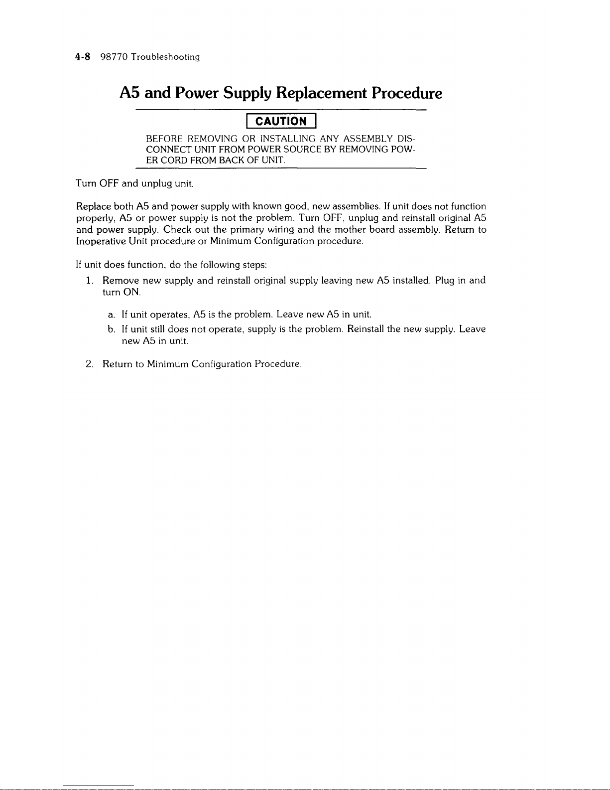
A5 and Power Supply Replacement Procedure
I CAUTION I
BEFORE REMOVING
OR
INSTALLING ANY ASSEMBLY DIS-
CONNECT UNIT FROM POWER SOURCE
BY REMOVING POW-
ER
CORD FROM BACK
OF
UNIT.
Turn OFF
and
unplug
unit.
Replace
both
AS
and
power
supply with known good, new assemblies. If unit
does
not
function
properly,
AS
or
power
supply
is
not
the problem. Turn OFF. unplug
and
reinstall original
AS
and
power
supply.
Check
out
the primary wiring
and
the
mother
board
assembly. Return to
Inoperative Unit
procedure
or
Minimum Configuration procedure.
If unit
does
function.
do
the following steps:
1.
Remove
new
supply
and
reinstall original supply leaving new
AS
installed. Plug
in
and
turn ON.
a.
If
unit operates,
AS
is
the problem. Leave new
AS
in
unit.
b.
If unit still
does
not
operate, supply
is
the problem. Reinstall the new supply. Leave
new
AS
in
unit.
2. Return to Minimum Configuration
Procedure.
98770
Troubleshooting
4-9
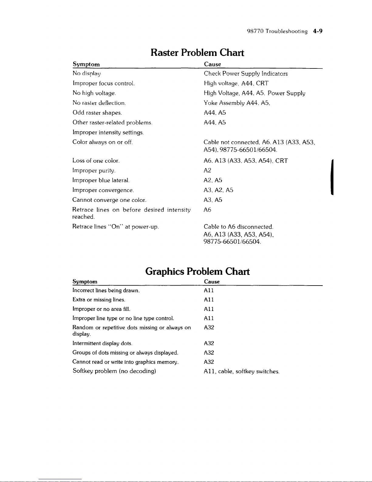
Raster Problem Chart
Symptom
No display
Improper focus control.
No high voltage.
No raster deflection.
Odd
raster shapes.
Other raster-related problems.
Improper intensity settings.
Color always
on
or
off.
Loss of
one
color.
Improper purity.
Improper blue lateral.
Improper convergence.
Cannot
converge
one
color.
Retrace
lines
on
before
desired
intensity
reached.
Retrace lines
"On"
at
power-up.
Cause
High voltage. A44. CRT
High Voltage.
A44.
AS.
Power
Supply
Yoke Assembly A44.
AS.
A44.AS
A44.AS
Cable not connected. A6. A13 (A33. AS3.
AS4).9877S-66S01/66S04.
A6. A13 (A33. AS3. AS4). CRT
A2
A2.AS
A3.A2.AS
A3.AS
A6
Cable to A6 disconnected.
A6, A13 (A33, AS3, AS4),
9877S-66S01/66S04.
Graphics Problem Chart
Symptom
Incorrect lines being drawn.
Extra
or
missing lines.
Improper or
no
area
fill.
Improper line type
or
no
line type control.
Random
or
repetitive dots missing
or
always
on
display.
Intermittent display dots.
Groups of dots missing
or
always displayed.
Cannot
read
or
write into graphics memory.
Softkey problem (no decoding)
Cause
All
All
All
All
A32
A32
A32
A32
All,
cable, softkey switches.
I
 Loading...