

Page 1

OWNER’S MANUAL
ECONO-MIZER
GRAIN SPREADERS
Models 982, 986 & 996
PNEG-1139
Date: 10-8-07
PNEG-1139
Page 2

Page 3
Econo-Mizer
Safety
SAFETY GUIDELINES
This manual contains information that is important for you, the owner/operator , to know and
understand. This information relates to protecting personal safety and preventing
equipment problems. It is the responsibility of the owner/operator to inform anyone
operating or working in the area of this equipment of these safety guidlines.T o help you
recognize this information, we use the symbols that are defined below.
Please read the manual and pay attention to these sections. Failure to read this manual
and it’s safety instructions is a misuse of the equipment and may lead to serious injury or death.
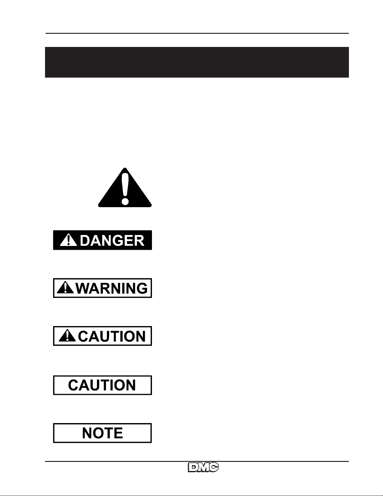
This is the safety alert symbol. It is used to alert you
to potential personal injury hazards. Obey all
safety messages that follow this symbol to avoid
possible injury or death.
DANGER indicates an imminently hazardous situation which, if not
avoided, will result in death or serious injury .
WARNING indicates a potentially hazardous situation which, if not
avoided, could result in death or serious injury .
CAUTION indicates a potentially hazardous situation which, if not
avoided, may result in minor or moderate injury .
CAUTION used without the safety alert symbol indicates a potentially
hazardous situation which, if not avoided, may result in property
damage.
NOTE indicates information about the equipment that you should pay
special attention to.
3
Page 4

Econo-Mizer
1. Disconnect all power before servicing or adjusting. Have bin properly grounded.
2. Do not enter a bin while the unit is operating without proper eye protection.
3. Do not attempt to service or adjust the unit from a ladder unless the ladder is
4. Power cords, plug and receptacles should be the grounded type to prevent injury.
5. All wiring should be done according to the National Electric Code and by a
6. Read and understand the operator’s manual.
WARNING:
Failure to follow these instructions may result in personal injury or property damage.
secured to another piece of equipment or to the bin. The grain spreader can
swing and will not support a ladder. Be sure electrical power is disconnected.
qualified electrician.
SPREADING CAPACITIES
Econo-Mizer 982 986 996
Heavy Grain 18'-30' 31'-48' 31'-48'
2500 BPH 3500 BPH
Heavy Grain 18'-27' 28'-42' 28'-42'
3500 BPH 5000 BPH
Light Grain 18'-24' 25'-36' 25'-36'
3500 BPH 5000 BPH
4
Page 5

Econo-Mizer
Installation
Figure 1: Hanger Brackets and Chains
The hanger brackets should be positioned
equally spaced around the outer fill hole lip of
the bin. Do not tighten the bracket hardware
until the spreader has been installed and
leveled. Hang the spreader from these brackets by hooking the two chains that are attached to each of the spreader support arms
to two adjacent hanger brackets. When
properly hung, each set of chains will form a
“V” and will restrict random movement of the
spreader.
The spreader can be installed at various
heights in the bin depending on the bin diameter and roof angle. The spreader should be
installed as level as possible by checking with
a level and adjusting the position of the hanger
brackets and/or the lengths of the chains.
Fig. 3
Fig. 4
Installation and Operation
Fig. 1
Fig. 2
Finish the installation by securely tightening
the hanger brackets.
Wiring: Refer to the Wiring Diagram and Tables A & B on the next p age.
ADJUSTMENT & OPERATION
Figure 2: Slide Gate Adjustment
The slide gates are provided in the pan to allow grain to be spread in the center of the bin. These are
usually to be open wider for smaller diameter bins.
Figure 3: Center Cone Adjustment
It is important that the incoming grain be directed onto the center of the baffle cone in order to disperse the grain evenly in the hopper . This cone functions as a flow control and can be adjusted by
lifting it from the spreader and placing the hairpin clip in one of the holes in the baffle post. The cone
needs to be adjusted higher above the spreader pan for greater capacities and lower for lesser
rates. Best spreading results are obtained when the cone is adjusted to maintain a cushion of grain
in the hopper .
Item 4: Slinger Adjustment
982, 986 & 996 Econo-Mizers have slingers that can be adjusted to accommodate various sizes of
bins and grain densities. The slingers will throw grain farther when in the most advanced position
(hole #1) and will not throw as far when in the swept back position (hole #3). A guide line to use for
adjusting is to use the third hole for 18 foot diameter bins, the middle hole for 24 - 30 foot bins and
the first hole for 33 foot and larger bins.
5
Page 6

Installation and Operation
(
)
)
Econo-Mizer
INSTALLATION
Use Tables A & B to determine the proper size of fuse protection and the length and size
of wiring required. Portable extension cords, if used, should be as short as possible to
minimize voltage drop. Cords that are too long, or cords that are made of inadequate wire
gauge, can cause the motor to fail.
TABLE A
MOTOR 25 FT 50 FT 100 FT 200 FT
982 (1/3 hp-115V) #18 GA #16 GA #12 GA #10 GA
986 (1 HP-230V) #14 GA #14 GA #12 GA #10 GA
996 (1-1/2 hp-220V) #14 GA #14 GA #12 GA #10 GA
TABLE B (FUSE SIZE
MOTOR
982 (1/3 hp-115V)
986 (1 HP-230V)
996 (1-1/2 hp-220V)
NON-TIME DELAY
15
15
20
WIRE SIZE
DISTANCE
TYPE OF FUS E
DUAL ELEMENT TIME DELAY
12
12
15
6
Page 7

Econo-Mizer
Installation and Operation
ADJUSTMENT & OPERATION OF
CONE HOPPER BAFFLE
The cone hopper baffle is used to restrict the entering grain and slow it down
enough to ensure that the cone will always be full and overflowing with grain. The
cone baffle should be adjusted high enough above the spreading pan to allow the
overflowing grain to flow between the hopper and the cone baffle and to not flow
over the sides of the main hopper. Entering grain should be directed onto the
expanded metal restrictor on top of the cone baffle.
ECONO-MIZER
305B007 (982, 986)
306B1001 (996)
CONE BAFFLE
7
Page 8

Parts
Econo-Mizer
Models 982, 986, & 996 Econ-Mizer Grain Spreaders
8
Page 9

Econo-Mizer
Parts
MODELS 982, 986 & 996 ECONO-MIZER
GRAIN SPREADERS PARTS LIST
Model s 982, 986, & 996 Econo-Mizer Gr ai n Spreader Part Li st s
Re f. Part No . Part No. P ar t No . De scri p t i o n
No. 982 986 996 982 986 996
1 301A0110 301A0110 301A0110 2 1 1 Sl ide Gat e
2 301A0122 302A0313 302A0313 1 1 1 Rubber Drive wheel
3 301B0220 301B0220 301B0220 3 3 3 Hanger Bracket
4 301B0221 301B0221 301B0221 3 3 3 Hanger U-Bolt Hook
5 302A0304 302A0304 302A0304 1 1 1 Mot or M ount P l ate
6 302A0311 302A0311 302A0311 1 1 1 Torsion Spring
7 304A0002 305A002 305A002 1 1 1 Hopper Bas e & Braces
8 304A0005 305A005 305A005 1 1 1 P an with S li ngers
9 304A0015 305A012 305A012 1 2 2 A djust abl e Sli nger
10 304B0001 304B0001 3061010 1 1 1 Hopper
11 304B0006 305B004 305B004 6 6 6 S upport Chain
12 304N0004 ---- ---- 1 - - 115V P ower Cord wi t h Loose Cli ps
---- 305N005 305N005 - 1 1 220V Power Cord with Loose Clips
13 305B007 305B 007 3061001 1 1 1 Hopper Baffle
14 P T0106 PT0109 P T0109 1 2 2 1" Bearing with Cast Housi ng
15 P T0202 PT0215 P T0215 1 2 2 1" Bearing with Lock i ng Collar
16 P T0401 PT0401 P T0401 1 2 2 1" Locking Coll ar
17 P T0415 ---- ---- 1 - - Bearing Housing-2 Hole
18 1EL0530 1EL0530 1EL0530 2 2 2 Flag Quick Disconnect Cli p
19 3EL5055 ---- ---- 1 - - 1/3 HP 115V
---- ---- 3EL 5088 - - 1 1-1/ 2 HP 230V TENV Motor
---- 3EL5082 ---- - 1 - 1HP TENV Motor
20 S-4198 S -4198 S -4198 2 1 1 1/4" W i ngnut
21 S-4663 ---- S -4663 3 - 1 3/ 8" Hex Lock Nut
22 ---- S-4 663 -- -- - 1 - 3/8 " He x Lo ck Nut
23 S-396 S-396 S -396 10 10 10 5/ 16" Hex Nut
24 ---- S -4663 S -4663 - 2 2 3/8" Hex Nut
25 S-3611 S-3611 S-3611 6 6 6 5/16" Hex F l ange Lock Nut
26 S-7186 S-7186 S-7186 2 2 2 1/4" x 1/ 4" S ock et Hd Set Screw
27 S-6369 S-6369 S-6369 2 1 1 1/4" x 3/ 4" Carraige Bolt
28 S-8072 S-8072 S-8072 4 4 4 5/16" x 3/4" Hex Hd B ol t
29 S - 7105 ---- ---- 2 - - 3/8" x 3/4" H ex Hd Bolt
---- S-7521 S-7521 - 2 2 3/8" x 1" Hex Hd B ol t
30 S-7744 S-7744 S-7744 1 1 1 3/8" x 5-1/2" Hex Hd Bolt
31 2FH0988 2FH0988 2FH0988 5 7 7 5/16" x 1/2" Hex F lange W hi z Loc k S c rew
32 S-6606 S-6606 S-6606 3 3 3 5/16" x 3/4" Hex
33 3FH0769 3FH0769 3FH0769 1 1 1 .08" x 1-5/8" Hair Pi n
34 S-2041 S -2041 S -2041 2 1 1 1/4" Loc k was her
35 S-1147 S -1147 S -1147 10 10 10 5/16" Loc k was her
36 S-1430 S -1430 S -1430 6 5 5 1/4" Loc k was her
37 S-1937 S-1937 S-1937 5 7 7 5/16" SAE Flat Washer
38 S-7409 ---- ---- 2 - - 3/8" SAE Flat Washer
---- S -1054 S -1054 - 2 2 3/8" Loc k W asher
39 S-6371 ---- ---- 1 - - 1/8" x 1" Square Key
---- S -8426 S -8426 - 1 2 1" x 3/ 16" Square K ey
No. Req.
9
Page 10

Trouble Shooting Guide
Econo-Mizer
TROUBLE SHOOTING
PROBLEM
Grain is high on
one side of bin.
Grain is high at the
center of bin.
Grain is low at the
center of bin.
Grain forms “donut”
a few feet from wall.
CORRECTION
a. Spreader is not hung level.
b. Grain is not hitting the center of the baffle
c. The baffle is too high causing the grain to slide off one side.
d. The flow of grain is not adequate to fill the center hopper ,
see instructions for cone baffle hopper .
a. Slide gate is open too far .
b. Check to make sure spreader is running.
c. Grain is overflowing the main hopper - raise center baffle
or slow grain flow rate.
a. Slide gate is not open enough.
b. Slingers on pan are set too far out.
a. Slingers on pan are set too far out (grain is hitting the wall
and bouncing back).
b. Open slide gate to fill center of bin.
c. Spreader model is not adequate for bin size.
Grain not getting
all the way to wall.
Spreader swings
when starting.
Spreader does
not run.
Spreader pan slows
down when loaded.
a. S preader pan is turning the wrong direction: Pan should
turn clockwise when viewed from the top.
b. Rubber drive wheel is slipping - replace if badly worn.
c. Spreader is hanging too high in the center of the bin.
d. Spreader model is not adequate for bin size.
a. Hanging chains are not installed correctly - they should
be equally spaced and positioned as in Figure 2 of
installation instructions.
a. Rubber drive wheel may be slipping due to excessive
moisture or broken motor mount spring.
b. Motor overload may have tripped. It will reset auto matically after the motor has cooled.
c. Blown fuse or circuit breaker.
d. Too much voltage drop. See T able A for proper wiring
size.
a. S preader pan is turning the wrong direction: Pan should
turn clockwise when viewed from the top.
10
Page 11

The GSI Group, Inc. Warranty
THE GSI GROUP, INC. (“GSI”) WARRANTS ALL PRODUCTS WHICH IT MANUFACTURES TO
BE FREE OF DEFECTS IN MATERIAL AND WORKMANSHIP UNDER NORMAL USAGE AND
CONDITIONS FOR A PERIOD OF 12 MONTHS AFTER RETAIL SALE TO THE ORIGINAL END
USER. THE PURCHASER’S SOLE REMEDY AND GSI’S ONLY OBLIGATION SHALL BE TO
REPAIR OR REPLACE, AT GSI’S OPTION AND EXPENSE, PRODUCTS THAT, IN GSI’S SOLE
JUDGMENT, CONTAIN A MATERIAL DEFECT DUE TO MATERIALS OR WORKMANSHIP.
ALL DELIVERY AND SHIPMENT CHARGES TO AND FROM GSI’S FACTORY WILL BE
PURCHASER’S RESPONSIBILITY. EXPENSES INCURRED BY OR ON BEHALF OF THE
PURCHASER WITHOUT PRIOR WRITTEN AUTHORIZATION FROM AN AUTHORIZED
EMPLOYEE OF GSI SHALL BE THE SOLE RESPONSIBILITY OF THE PURCHASER.
EXCEPT FOR THE LIMITED WARRANTY EXPRESSED ABOVE, GSI MAKES NO FURTHER
WARRANTY OF ANY KIND, EXPRESS OR IMPLIED, INCLUDING, WITHOUT LIMITATION,
WARRANTIES OF MERCHANTABILITY OR FITNESS FOR A PARTICULAR PURPOSE OR
USE IN CONNECTION WITH (I) PRODUCT MANUFACTURED OR SOLD BY GSI OR (ii) ANY
ADVICE, INSTRUCTION, RECOMMENDATION OR SUGGESTION PROVIDED BY AN AGENT,
REPRESENTATIVE OR EMPLOYEE OF GSI REGARDING OR RELATED TO THE
CONFIGURATION, INSTALLATION, LAYOUT, SUITABILITY FOR A PARTICULAR PURPOSE,
OR DESIGN OF SUCH PRODUCTS.
GSI SHALL NOT BE LIABLE FOR ANY DIRECT, INDIRECT, INCIDENTAL OR
CONSEQUENTIAL DAMAGES, INCLUDING, WITHOUT LIMITATION, LOSS OF ANTICIPATED
PROFITS OR BENEFITS. PURCHASER’S SOLE AND EXCLUSIVE REMEDY IS AS SET FORTH
IN THE LIMITED WARRANTY EXPRESSED ABOVE, WHICH SHALL NOT EXCEED THE
AMOUNT PAID FOR THE PRODUCT PURCHASED. THIS WARRANTY IS NOT
TRANSFERABLE AND APPLIES ONLY TO THE ORIGINAL PURCHASER. GSI SHALL HAVE
NO OBLIGATION OR RESPONSIBILITY FOR ANY REPRESENTATIONS OR WARRANTIES
MADE BY OR ON BEHALF OF ANY DEALER, AGENT OR DISTRIBUTOR OF GSI.
GSI ASSUMES NO RESPONSIBILITY FOR CLAIMS RESULTING FROM ERECTION DEFECTS
OR UNAUTHORIZED MODIFICATIONS TO PRODUCTS WHICH IT MANUFACTURED.
MODIFICATIONS TO PRODUCTS NOT SPECIFICALLY DELINEATED IN THE MANUAL
ACCOMPANYING THE EQUIPMENT AT INITIAL SALE WILL NULLIFY THE PRODUCT
WARRANTY THAT MIGHT HAVE BEEN OTHERWISE AVAILABLE.
THE FOREGOING WARRANTY SHALL NOT EXTEND TO PRODUCTS OR PARTS WHICH
HAVE BEEN DAMAGED BY NEGLIGENT USE, MISUSE, ALTERATION OR ACCIDENT. THIS
WARRANTY EXTENDS SOLELY TO ONLY PRODUCTS MANUFACTURED BY GSI. THIS
WARRANTY IS EXCLUSIVE AND IN LIEU OF ALL OTHER WARRANTIES EXPRESS OR
IMPLIED. GSI RESERVES THE RIGHT TO MAKE DESIGN OR SPECIFICATION CHANGES AT
ANY TIME.
PRIOR TO INSTALLATION, PURCHASER HAS THE RESPONSIBILITY TO COMPLY WITH
ALL FEDERAL, STATE AND LOCAL CODES WHICH MAY APPLY TO THE LOCATION AND
INSTALLATION OF PRODUCTS MANUFACTURED OR SOLD BY GSI.
PHLEGAL: #1832020 v1 (139LG01!.DOC) (revised December 2005)
Page 12

This Equipment shall be installed in accordance
with the cur rent installation codes and applicable
regulations which should be carefully followed in
all cases. Authorities having jurisdiction should be
consulted before installation occurs.
For more information, contact the DMC Distribution Center closest to you.
Illiana Distribution Center
1004 E. Illinois S t.
Assumption, Illinois 62510
Phone: 217-226-5100
F AX : 217-226-5070
Clear Lake Distribution Center
5205 4th Ave South
Clear Lake, Iowa 50428
Phone: 641-357-3386
FAX : 641-357-1928
internet: http://www .dmc-davidmanufacturing.com
Copyright © 1999 by The GSI Group
Printed in the USA
 Loading...