

HP
9800
Computers
9845B/C
CE
Handbook
Part
No.
09845-90039
E0l82
Requires Binder
No.
9282-0683
Fli;-
HEWLETT
a:~
PACKARD
Printed
in
U.S.A.
First Edition, January 1982
9845B/C
CE
Handbook
© Copyright Hewlett-Packard Company, 1982
This document refers to proprietary computer software which is protected by copyright
All rights are reserved. Copying or other reproduction of this program except for archival
purposes
is
prohibited without the prior written consent of Hewlett-Packard Company
Hewlett-Packard
Company
3404 East Harmony Road, Fort Collins, Colorado 80525
Product Information
I
Environmental/InstallationlPM
I
Configuration
I
Troubleshooting
II
Diagnostics
I
Adjustments
•
Peripherals
•
Replaceable Parts
•
Diagrams
•
Reference
II
Service Notes
III
ii
Printing History
New editions of this manual
will
incorporate
all
material updated since the previous edition. Update
packages may
be
issued between editions and contain replacement and additional pages to be
merged into the manual by the user. Each updated page
will
be indicated by a revision date at the
bottom of the page. A vertical bar
in
the margin indicates the changes on each page. Note that pages
which are rearranged due to changes on a previous page are not considered revised.
The manual printing date and part number indicate
its
current edition. The printing date changes
when a new edition
is
printed. (Minor corrections and updates which are incorporated at reprint do
not cause the date to change. ) The manual part number changes when extensive technical changes
are incorporated.
January 1982 ... First Edition
April
1984
... Second Edition. Updated pages.
warranty Statement
Hewlett-Packard
products
are warranted against defects
In
matenals and workmanship For Hewlett-Packard Fort Collins
Systems Division products sold
in
the U S.A and Canada.
thiS
warranty applies for ninety (90) days from the date of
delivery'
Hewlett-Packard will, at its option, repair or replace equipment which proves to be defective during the warranty period This
warranty InCluoes ldoor, parts, dllO
~urfdl.,e
lJO'o'el
vu;::.~;::.,
Ii
oily
LYUIj.J;i-,6i-,:
;6:U~IIC~:':::'
HG;,:c::-ro.c~a~c
fc~
~Gf=:a:~
:-T',
....
5:
b2
shipped
freight
prepaid.
Repairs necessitated by misuse of the equipment, or
by
hardware, software, or Interfacing not
provided
by
Hewlett-Packard are not covered by this warranty
HP warrants that its software and firmware designated by
HP
for use with a
CPU
will execute its programming instructions
when properly installed on that
CPU HP does not warrant that the operation of the CPU, software. or firmware will be uninter-
rupted or error free
HEWLETT-PACKARD MAKES NO WARRANTY OF ANY KIND WITH REGARD
TO
THIS MATERIAL. INCLUDING, BUT NOT
LIMITED TO,
THE IMPLIED WARRANTIES OF MERCHANTABILITY AND FITNESS
FOR
A PARTICULAR PURPOSE. Hewlett-
Packard shall
not be liable for errors contained herein or for Incidental or consequential damages
In
connection with the
furnishing, performance or use of this
matenal
• For other countnes. contact your local Sales and Support Office to determine warranty terms
09845-90039. rev.
4184
Iii
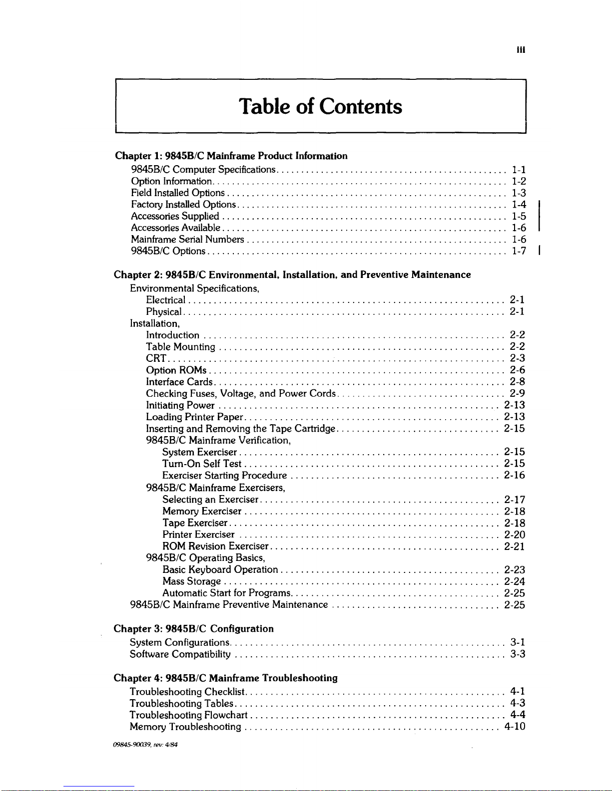
Table
of
Contents
Chapter
1:
9845B/C Mainframe Product Information
9845B/C Computer Specifications. . . . . . . . . . . . . . . . . . . . . . . . . . . . . . . . . . . . . . . . . . . . .
..
1-1
Option Information
............................................................
1-2
Field Installed Options. . . . . . . . . . . . . . . . . . . . . . . . . . . . . . . . . . . . . . . . . . . . . . . . . . . . . . .
..
1-3
Factory Installed Options. . . . . . . . . . . . . . . . . . . . . . . . . . . . . . . . . . . . . . . . . . . . . . . . . . . . .
..
1-4
Accessories Supplied
.........................................................
, 1-5
Accessories Available
..........................................................
1-6
Mainframe Serial Numbers . . . . . . . . . . . . . . . . . . . . . . . . . . . . . . . . . . . . . . . . . . . . . . . . . . .
..
1-6
9845B/C Options. . . . . . . . . . . . . . . . . . . . . . . . . . . . . . . . . . . . . . . . . . . . . . . . . . . . . . . . . . .
..
1-7
Chapter
2:
9845B/C
Environmental, Installation,
and
Preventive
Maintenance
Environmental Specifications,
Electrical. . . . . . . . . . . . . . . . . . . . . . . . . . . . . . . . . . . . . . . . . . . . . . . . . . . . . . . . . . . .
..
2-1
PhYSical.
. . . . . . . . . . . . . . . . . . . . . . . . . . . . . . . . . . . . . . . . . . . . . . . . . . . . . . . . . . . .
..
2-1
Installation,
Introduction . . . . . . . . . . . . . . . . . . . . . . . . . . . . . . . . . . . . . . . . . . . . . . . . . . . . . . . . .
..
2-2
Table Mounting
........................................................
2-2
CRT
..................................................................
2-3
Option ROMs. . . . . . . . . . . . . . . . . . . . . . . . . . . . . . . . . . . . . . . . . . . . . . . . . . . . . . . .
..
2-6
Interface Cards. . . . . . . . . . . . . . . . . . . . . . . . . . . . . . . . . . . . . . . . . . . . . . . . . . . . . . .
..
2-8
Checking Fuses, Voltage, and Power Cords
.................................
2-9
Initiating Power
......................................................
, 2-13
Loading Printer
Paper
.................................................
,
2-13
Inserting
and
Removing the Tape Cartridge
...............................
, 2-15
9845B/C Mainframe Verification,
System Exerciser
..................................................
, 2-15
Turn-On Self Test
.................................................
,
2-15
Exerciser Starting Procedure
.........................................
2-16
9845B/C Mainframe ExerCisers,
Selecting an Exerciser
..............................................
, 2-17
Memory Exerciser
..................................................
2-18
Tape Exerciser
....................................................
,
2-18
Printer Exerciser
..................................................
,
2-20
ROM
Revision Exerciser
.............................................
2-21
9845B/C Operating Basics,
Basic Keyboard Operation. . . . . . . . . . . . . . . . . . . . . . . . . . . . . . . . . . . . . . . . .
..
2-23
Mass Storage
.....................................................
,
2-24
Automatic Start for Programs. . . . . . . . . . . . . . . . . . . . . . . . . . . . . . . . . . . . . . .
..
2-25
9845B/C Mainframe Preventive Maintenance
................................
, 2-25
Chapter
3:
9845B/C
Configuration
System Configurations. . . . . . . . . . . . . . . . . . . . . . . . . . . . . . . . . . . . . . . . . . . . . . . . . . . .
..
3-1
Software Compatibility . . . . . . . . . . . . . . . . . . . . . . . . . . . . . . . . . . . . . . . . . . . . . . . . . . .
..
3-3
Chapter
4:
9845B/C
Mainframe Troubleshooting
Troubleshooting Checklist
...................................................
4-1
Troubleshooting Tables
.....................................................
4-3
Troubleshooting Flowchart
..................................................
4-4
Memory Troubleshooting
.................................................
,
4-10
09845-90039, rev: 4/84
Iv
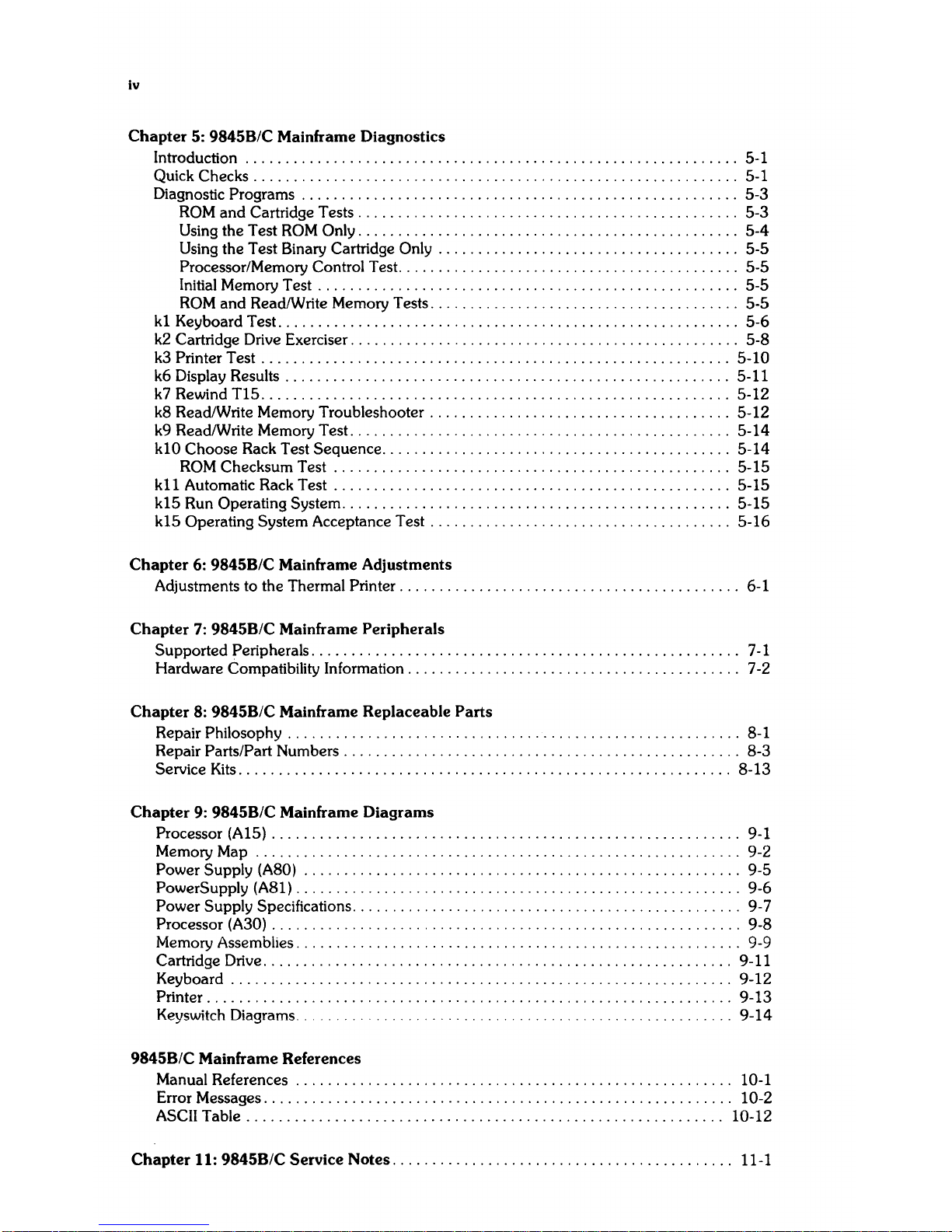
Chapter
5:
98458/C
Mainframe Diagnostics
Introduction
...
. . . . . . . . . . . . . . . . . . . . . . . . . . . . . . . . . . . . . . . . . . . . . . . . . . . . . . . . .
..
5-1
QUick
Checks . . . . . . . . . . . . . . . . . . . . . . . . . . . . . . . . . . . . . . . . . . . . . . . . . . . . . . . . . . .
..
5-1
Diagnostic
Programs . . . . . . . . . . . . . . . . . . . . . . . . . . . . . . . . . . . . . . . . . . . . . . . . . . . . .
..
5-3
ROM
and Cartridge Tests. . . . . . . . . . . . . . . . . . . . . . . . . . . . . . . . . . . . . . . . . . . . . .
..
5-3
Using the Test
ROM
Only. . . . . . . . . . . . . . . . . . . . . . . . . . . . . . . . . . . . . . . . . . . . . .
..
5-4
Using the Test Binary Cartridge Only . . . . . . . . . . . . . . . . . . . . . . . . . . . . . . . . . . . .
..
5-5
Processor/Memory Control Test. . . . . . . . . . . . . . . . . . . . . . . . . . . . . . . . . . . . . . . . .
..
5-5
Initial Memory Test . . . . . . . . . . . . . . . . . . . . . . . . . . . . . . . . . . . . . . . . . . . . . . . . . . .
..
5-5
ROM
and ReadlWrite Memory Tests. . . . . . . . . . . . . . . . . . . . . . . . . . . . . . . . . . . . .
..
5-5
kl
Keyboard Test. . . . . . . . . . . . . . . . . . . . . . . . . . . . . . . . . . . . . . . . . . . . . . . . . . . . . . . .
..
5-6
k2
Cartridge Drive Exerciser. . . . . . . . . . . . . . . . . . . . . . . . . . . . . . . . . . . . . . . . . . . . . . .
..
5-8
k3
Printer Test
...........................................................
5-10
k6 Display Results . . . . . . . . . . . . . . . . . . . . . . . . . . . . . . . . . . . . . . . . . . . . . . . . . . . . . .
..
5-11
k7
Rewind
TIS
...........................................................
5-12
k8 Read/Write Memory Troubleshooter
......................................
5-12
k9 Read/Write Memory Test. . . . . . . . . . . . . . . . . . . . . . . . . . . . . . . . . . . . . . . . . . . . . .
..
5-14
kl0
Choose Rack Test Sequence
............................................
5-14
ROM
Checksum Test
..................................................
5-15
k11 Automatic Rack Test
..................................................
5-15
k15 Run Operating
System
.................................................
5-15
k15 Operating
System Acceptance Test
......................................
5-16
Chapter
6:
98458/C
Mainframe Adjustments
Adjustments to the Thermal
Printer. . . . . . . . . . . . . . . . . . . . . . . . . . . . . . . . . . . . . . . . .
..
6-1
Chapter
7:
98458/C
Mainframe Peripherals
Supported Peripherals
......................................................
7-1
Hardware Compatibility Information. . . . . . . . . . . . . . . . . . . . . . . . . . . . . . . . . . . . . . . .
..
7-2
Chapter
8:
98458/C
Mainframe Replaceable
Parts
Repair Philosophy . . . . . . . . . . . . . . . . . . . . . . . . . . . . . . . . . . . . . . . . . . . . . . . . . . . . . . .
..
8-1
Repair
Parts/Part Numbers
..................................................
8-3
Service Kits. . . . . . . . . . . . . . . . . . . . . . . . . . . . . . . . . . . . . . . . . . . . . . . . . . . . . . . . . . . .
..
8-13
Chapter
9:
98458/C
Mainframe
Diagrams
Processor (AI5)
...........................................................
9-1
Memory Map
...
. . . . . . . . . . . . . . . . . . . . . . . . . . . . . . . . . . . . . . . . . . . . . . . . . . . . . . . .
..
9-2
Power Supply (A80)
.......................................................
9-5
PowerSupply (A81)
........................................................
9-6
Power Supply SpeCifications
.................................................
9-7
Processor (A30)
...........................................................
9-8
Memory Assemblies. . . . . . . . . . . . . . . . . . . . . . . . . . . . . . . . . . . . . . . . . . . . . . . . . . . . . .
..
9-9
Cartridge Drive. . . . . . . . . . . . . . . . . . . . . . . . . . . . . . . . . . . . . . . . . . . . . . . . . . . . . . . . .
..
9-11
Keyboard
...............................................................
9-12
Printer. . . . . . . . . . . . . . . . . . . . . . . . . . . . . . . . . . . . . . . . . . . . . . . . . . . . . . . . . . . . . . . .
..
9-13
Keyswitch Diagrams. . . . . . . . . . . . . . . . . .
.................
9-14
98458/C
Mainframe References
Manual References
..
. . . . . . . . . . . . . . . . . . . . . . . . . . . . . . . . . . . . . . . . . . . . . . . . . . .
..
10-1
Error Messages. . . . . . . . . . . . . . . . . . . . . . . . . . . . . . . . . . . . . . . . . . . . . . . . . . . . . . . . .
..
10-2
ASCII Table
............................................................
10-12
Chapter
11:
98458/C
Service Notes
...........................................
11-1
1-1
L.....-
__
9_84_5_B_I_C_M_aI_·_nfr_am_e
__
----'
I
Chalp~
I
_
Product
Information
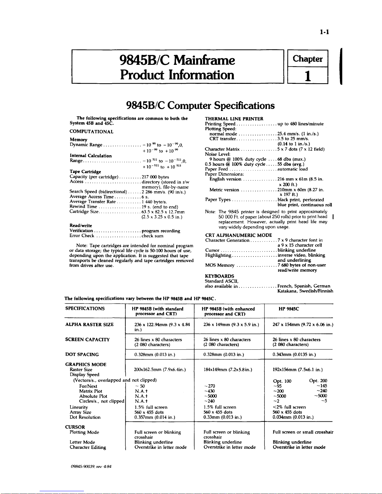
9845B/C Computer Specifications
The
following specifications are common to
both
the
System
45B
and
45C.
COMPUTATIONAL
Memory
Dynamic Range
.... , .,
..........
-10
99 to
-10-99,0,
+
10-
99
to +
10
99
Internal Calculation
Range
................
.
Tape Cartridge
....
-10
511
to
-10-
511
,0,
+
10-
511
to +
10
511
Capacity (per cartridge)
..........
217000 bytes
Access.
. . . . . . . . . . . . . . . .
..
directory (stored in r/w
memory), file-by-name
Search Speed (bidirectional)
.....
2286
mmls.
(90
in/s.)
Average Access Time
...........
6 s.
Average Transfer
Rate.
1
440
byte/so
Rewind
Time.
. . .
.....
19
s. (end to end)
Cartridge
Size. . . .63.5 x 82.5 x 12.7mm
(2.5 x 3.25 x
0.5 in.)
Read/write
Verification
.....................
program recording
Error Check
....................
check
sum
Note: Tape cartridges are intended for nominal program
or
data storage; the typical life cycle is 50-100 hours of use,
depending
upon
the application. It is suggested that tape
transports be cleaned regularly
and
tape cartridges removed
from drives after use.
THERMAL LINE
PRINTER
Printing Speed
..................
up
to
480
lines/minute
Plotting
Speed:
normal
mode
.................
25.4 mmls.
(1
in./s.)
CRT transfer
..................
3.5 to
25
mmls.
(0.14 to 1 in./s.)
Character
Matrix.
. . . . . . . . .
.5
x 7 dots
(7 x 12
field)
Noise Level:
9 hours
@
100%
duty
cycle
....
68
dba (max.)
0.5
hours @ 100%
duty
cycle
.....
55
dba
(avg.)
Paper
Feed.
. . . . .
.. . ...........
automatic load
Paper Dimensions:
English version
...............
216
mm
x 61m (S.5 in.
x
200
ft.)
Metric version
................
210mm x 60m (8.27 in.
x
197
ft.)
Paper Types
....................
black print, perforated
blue print, continuous roll
Note: The
9845
printer
is
designed to print approximately
50
000
Ft.
of paper (about
250
rolls) prior to print head
replacement. However, actually print head
life
may
vary
Widely
depending upon usage.
CRT
ALPHANUMERIC MODE
Character Generation
............
7 x 9 character font in
a 9 x
15
character cell
Cursor
.........................
blinking underline
Highlighting
....................
inverse video, blinking
and
underlining
MOS Memory
......
.
........ 7 680
bytes of non-user
read/write memory
KEYBOARDS
Standard ASCII,
also available in
.................
French, Spanish,
German
Katakana, SwedishlFinnish
The
following specifications vary
between
the HP
9845B
and
HP 9845C.
SPECIFICATIONS
HP
9845B
(with
standard
HP
9845B
(with
enhanced
HP 9845C
processor
and
CRT)
processor
and
CRT)
ALPHA RASTER SIZE
236
x 122.94mm (9.3 x 4.84
236
x 149mm (9.3 x 5.9 in.) 247 x 154mm (9.72 x 6.06 in.)
in.)
SCREEN CAPACITY
26
lines x
80
characters
26
lines x
80
characters
26
lines x 80 characters
(2
080
characters)
(2
080
characters) (2080 characters)
DOT
SPACING 0.32Smm (0.013 in.) 0.32Smm (0.013 in.) 0.343mm (0.0135 in.)
GRAPHICS MODE
Raster Size
200xI62.5mm
(7.9x6.4in.)
184x149mm (7.2x5.8in.) 192xl56mm (7.5x6.1 in.)
Display
Speed
(Vectors/s., overlapped
and
not clipped)
Opt.
100
Opt.
200
For/Next -SO
-270
-95
-145
Matrix Plot
N.A.t
-430
-200
-240
Absolute Plot
N.A.t
-5000 -5000
-5000
Circles/s., not clipped
N.A.t
-240
-2
-5
Linearity
1.5% full screen
1.5% full screen <2% full screen
Array
Size
560 x 455
dots
560 x 455
dots 560 x
455
dots
Dot Resolution
0.357mm (0.014 in.)
0.33mm (0.013 in.) O.034mm (0.013 in.)
CURSOR
Plotting Mode Full screen
or
blinking
Full screen or blinking Full screen or small crosshair
crosshair
crosshair
Letter Mode Blinking underline
Blinking underline
Blinking underline
Character Editing
Overstrike in letter mode Overstrike in letter
mode
Overstrike in letter
mode
09845-90039. rev:
4184
I
1-2
9845B/C
Mainframe
Product
Information
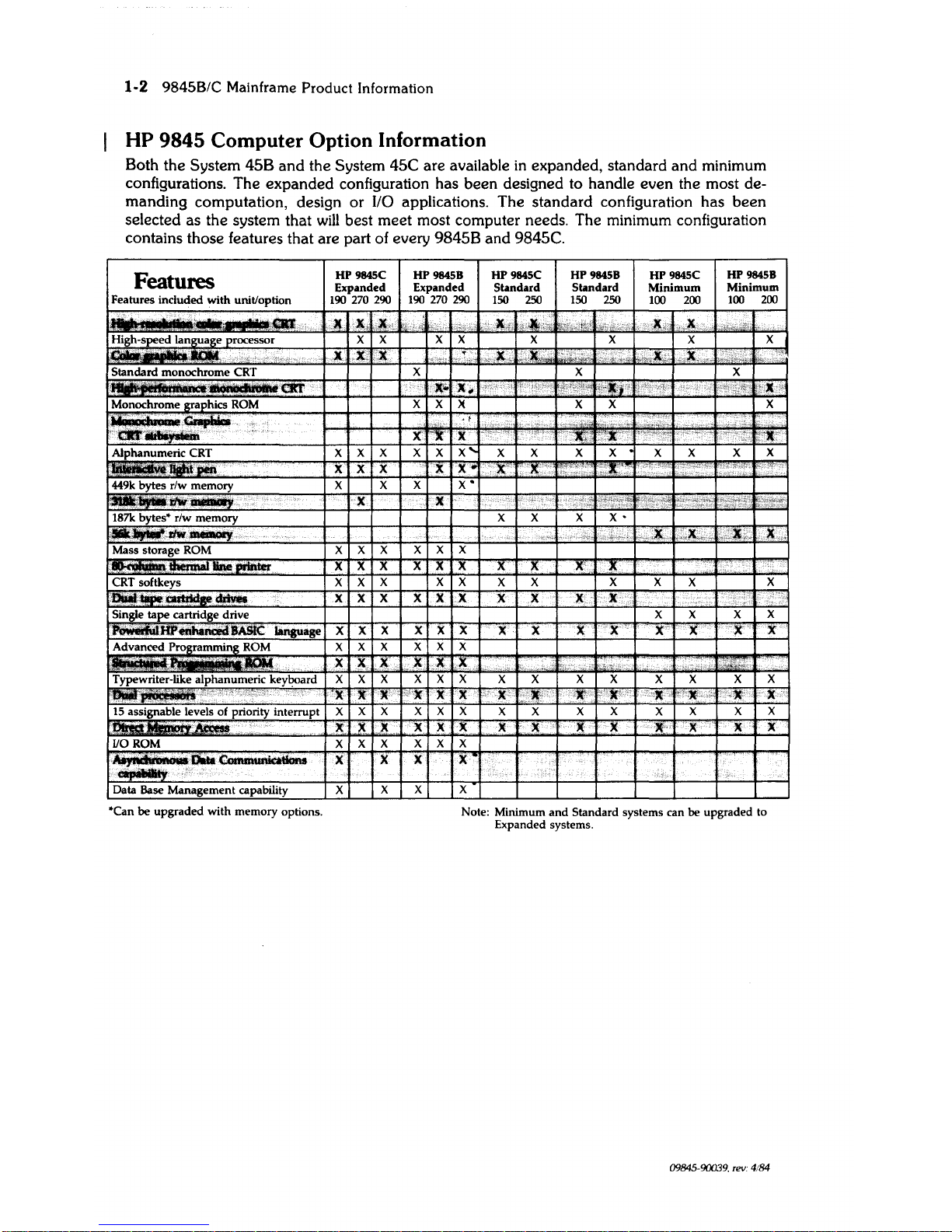
HP
9845
Computer Option Information
Both the System 45B
and
the System 45C are available
in
expanded, standard
and
minimum
configurations. The expanded configuration has been designed to handle even the most demanding computation, design
or
I/O applications. The standard configuration has
been
selected as the system that
will
best meet most computer needs. The minimum configuration
contains those features that are part of every 9845B and 9845C.
Features
Features included
with
unit/option
High-speed language processor
,::"',.,
:,"';
Standard
monochrome
CRT
Monochrome graphics
ROM
"
Alphanumeric CRT
-449k bytes
r/w
memory
rJti!f~
'.
187k
bytes'
r/w
memory
~~,rlw~
,.
Mass storage ROM
·JnePMter
CRT softkeys
...
Single
tape
cartridge drive
enhaJ\a!d
BASIC
language
Advanced Programming ROM
Typewriter-like alphanumeric keyboard
.~~
...
':
~,
~
"',"
15
assignable levels of priority interrupt
I10ROM
.,.....IIU.ft..
..
~
~.,
Data Base
Management
capability
'Can
be
upgraded
with
memory options,
HP 9845C
HP
984SB
HP 984SC HP 9845B
HP
9845C
HP9845B
Expanded Expanded
Standard Standard
Minimum
Minimum
190
270 290
190
270 290
ISO
250
ISO
250
100
200
100
200
,It
X,
"I.,
~4
k
,C;
:~,£j
.~,
,,",~
,i~"
~,
"X
,j,,,
;,~;,
X X
X X
X X X
X
X
lC
r.lt
,'i',
:"~""
",X"
,'It
. '
..
'~"
.
,X",
~lh",
h"
,',r,
X X X
X ..
X
..
:V', "
if
"
'"',,,
'''.:1
'~":
','1:,'
"
",~wn
~"X";
X X
)(
X X
X
./
..
,l.
X'
"X.
X
~:~
:.:.~
,
"
'~
X
X X X X
X
....
X X
X X
X
X X
X
X X
X
X X
X'
}[
,I,
.
,;11,;:
. "
",'"
7l
X X
X
X'
X X
.",'
.'"
l."":
,
..
X X X
X'
''',
._".
,X
,.~X'"
I,,~J;;
X
X
X X X X
X
X X X
X
X X X
)(
X' X
X X
X X X
X X
X X
X
X
X
X X X X X
X
X
X X
' ,
X X X
X
X
X X X X X X X
X
X
X'
X
X
X
X
X X X X X
X
X,
X
X
)t
,)(
,
U,L
'.
~,.
X X X
X X X
X X X X X X X
X
'X
XC
X
<"X
X X
X
X'
'X:'
~"X"
X
"",.xc,,,,:
'la: X
X X
X X X
X,
}(
,X
X
X
X
X X X
X
X
X X
X
X X
X
X X X
X
X X
X
X
X X
.X
X
X,
X X
X
X
"
X
Note: Minimum
and
Standard
systems can be
upgraded
to
Expanded systems,
X
X
09845-90039, rev:
4184
9845B/C
Mainframe
Product
Information
1-3
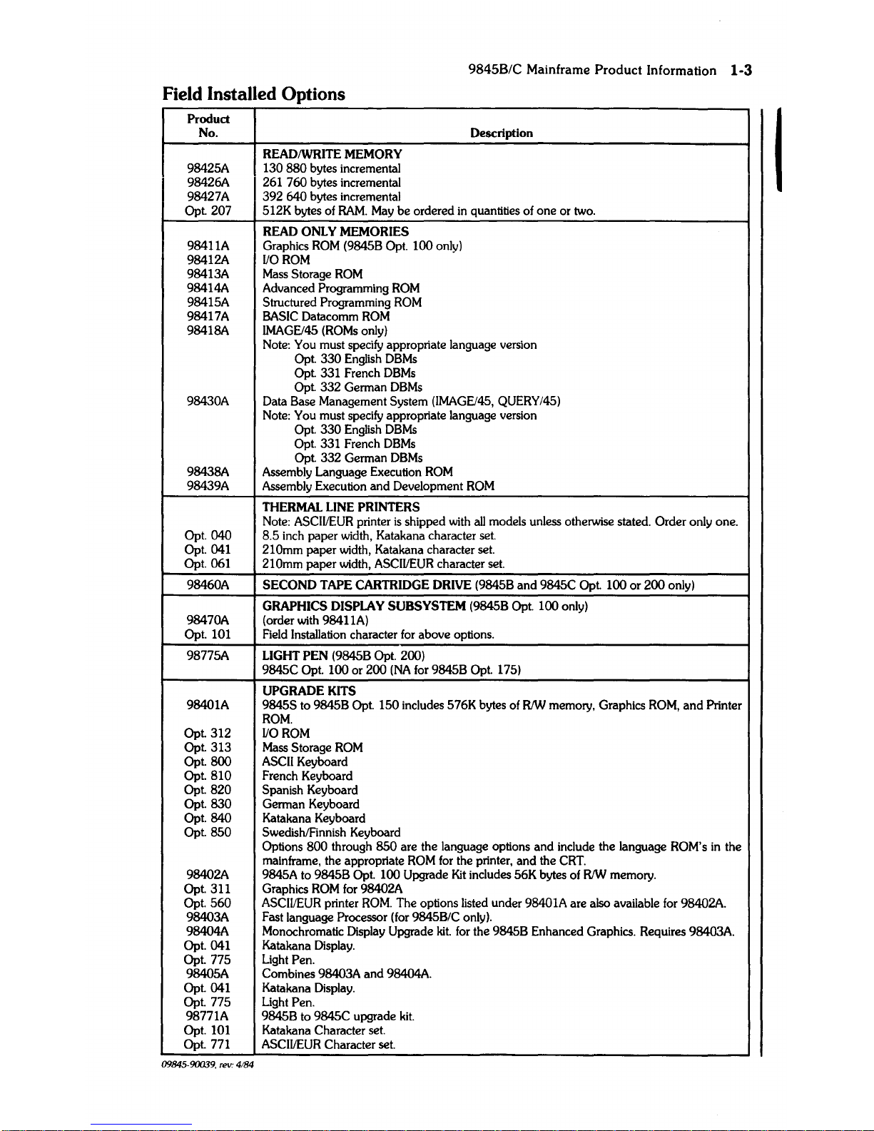
Field Installed Options
Product
No. Description
READIWRITE
MEMORY
98425A 130
880
bytes incremental
98426A 261
760
bytes incremental
98427A
392
640
bytes incremental
I
Opt
207
512K bytes of
RAM.
May
be
ordered
in
quantities of one or two.
READ
ONLY MEMORIES
98411A
Graphics
ROM
(9845B Opt.
100
only)
98412A
110
ROM
98413A Mass Storage
ROM
98414A Advanced Programming
ROM
98415A Structured Programming
ROM
98417A
BASIC Datacomm
ROM
98418A IMAGEl45 (ROMs only)
Note:
You must specify appropriate language version
Opt.
330
English
DBMs
Opt. 331 French
DBMs
Opt
332
German
DBMs
98430A Data Base Management System (IMAGEl45, QUERY/45)
Note: You must specify appropriate language version
Opt.
330
English
DBMs
Opt. 331 French
DBMs
Opt. 332 German
DBMs
98438A
Assembly Language Execution
ROM
98439A Assembly Execution
and
Development
ROM
THERMAL LINE PRINTERS
Note: ASCII/EUR printer
is
shipped with
all
models unless otherwise stated. Order only one.
Opt.
040
8.5 inch paper width, Katakana character set.
Opt.
041 210mm paper width, Katakana character set.
Opt.
061
210mm paper width, ASCIIIEUR character set.
98460A
SECOND
TAPE CARTRIDGE DRIVE (9845B
and
9845C
Opt
100
or
200
only)
GRAPHICS DISPLAY
SUBSYSTEM (9845B Opt. 100 only)
98470A (order with 98411A)
Opt. 101 Field Installation character
for
above options.
98775A LIGHT PEN (9845B Opt.
200)
9845C
Opt.
100
or
200
(NA
for 9845B Opt. 175)
UPGRADE KITS
98401A 9845S to 9845B Opt.
150
includes 576K bytes of
RIW
memory, Graphics
ROM,
and
Printer
ROM.
Opt
312
110
ROM
Opt
313
Mass Storage
ROM
Opt.
800
ASCII Keyboard
Opt.
810
French Keyboard
Opt.
820
Spanish Keyboard
Opt.
830
German Keyboard
Opt.
840
Katakana Keyboard
Opt
850
SwedishlFinnish Keyboard
Options
800
through
850
are the language options
and
include the language ROM's
in
the
mainframe, the appropriate
ROM
for
the printer,
and
the CRT.
98402A 9845A to 9845B Opt.
100 Upgrade
Kit
includes 56K bytes of
RIW
memory.
Opt. 311 Graphics
ROM
for 98402A
Opt.
560
ASCIIIEUR printer
ROM.
The options listed under 98401A are also available
for
98402A
98403A
Fast language Processor (for
9845B/C only).
98404A
Monochromatic Display
Upgrade
kit.
for the 9845B Enhanced Graphics. Requires 98403A.
Opt.
041 Katakana Display.
Opt. 775 Light
Pen.
98405A
Combines 98403A
and
98404A.
Opt.
041 Katakana Display.
Opt. 775 Light
Pen.
98771A
9845B to 9845C upgrade
kit.
Opt. 101 Katakana Character set.
Opt. 771
ASCII/EUR Character set.
09845·90039.
rev:
4184
1-4
98458/C
Mainframe
Product
Information
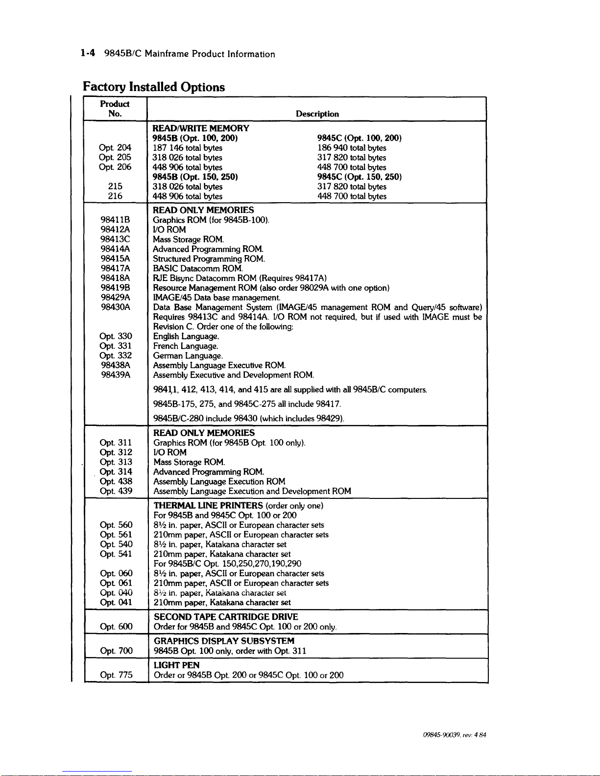
Factory Installed Options
Product
No. Description
READIWRITE MEMORY
98458
(Opt. 100,
2(0)
9845C (Opt. 100,
2(0)
Opt.
204
187
146
total bytes
186
940
total bytes
Opt.
205
318026
total bytes
317820
total bytes
Opt.
206
448
906
total bytes 448 700 total bytes
98458
(Opt. 150, 250) 9845C (Opt.
150,250)
215
318026
total bytes 317
820
total bytes
216
448
906
total bytes
448 700 total bytes
READ
ONLY MEMORIES
98411B
Graphics
ROM
(for 9845B-l(0).
98412A
1/0
ROM
98413C
Mass Storage
ROM.
98414A Advanced Programming
ROM.
98415A
Structured Programming
ROM.
98417A BASIC Datacomm
ROM.
98418A RJE Bisync Datacomm
ROM
(Requires 98417
A)
984198
Resource Management
ROM
(also order 98029A with one option)
98429A IMAGE/45 Data base management.
98430A Data Base Management System
(IMAGEl45
management
ROM
and
Query/45 software)
Requires 98413C and 98414A.
110
ROM
not required, but
if
used with
IMAGE
must be
Revision
C.
Order one of the
follOwing:
Opt.
330
English Language.
Opt. 331
French Language.
Opt. 332 German Language.
98438A Assembly Language Executive
ROM.
98439A Assembly Executive
and
Development
ROM.
984\1,
412, 413, 414, and 415 are
all
supplied with
all
9845B/C computers.
9845B-175, 275, and 9845C-275
all
include 98417.
9845B/C-280 include
98430
(which includes 98429).
READ
ONLY MEMORIES
Opt. 311
Graphics
ROM
(for 9845B Opt. 100 only).
Opt.
312
110
ROM
Opt. 313
Mass Storage
ROM.
. Opt.
314
Advanced Programming
ROM
.
Opt.
438
Assembly Language Execution
ROM
Opt. 439
Assembly Language Execution and Development
ROM
THERMAL LINE PRINTERS (order only one)
For
98458
and
9845C Opt. 100 or 200
Opt.
560
81/2
in.
paper, ASCII or European character sets
Opt. 561 210mm paper,
ASCII
or European character sets
Opt. 540
81/2
in.
paper, Katakana character set
Opt. 541 210mm paper. Katakana character set
For
9845B/C Opt. 150,250,270,190,290
Opt.
060
8112
in.
paper,
ASCII
or European character sets
Opt.
061 210mm paper,
ASCII
or European character sets
Opt.
040
8
1
;2
in.
paper, Katakana character set
Opt.
041 210mm paper, Katakana character set
SECOND
TAPE CARTRIDGE DRIVE
Opt. 600 Order for
98458
and 9845C Opt. 100 or 200 only.
GRAPHICS
DISPLAY SU8SYSTEM
Opt. 700 9845B Opt.
100
only, order with Opt. 311
LIGHT PEN
Opt. 775
Order or
98458
Opt.
200
or 9845C Opt. 100 or
200
09845-90039. rev. 4 84
9845B/C
Mainframe
Product
Information
1-5
Product
No.
Description
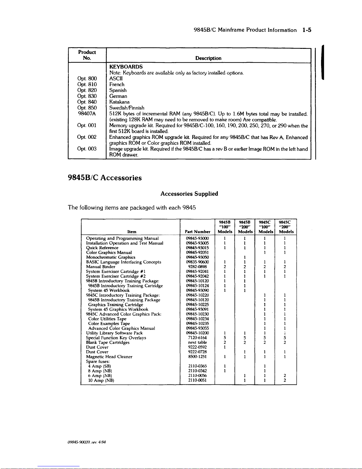
KEYBOARDS
I
Note: Keyboards are available only
as
factory installed options.
Opt.
800
ASCII
I
Opt. 810 French
Opt.
820
Spanish
Opt.
830
German
Opt.
840
I Katakana
I
Opt.
850
SwedishlFinnish
98407A
512K
bytes of incremental
RAM
(any 9845B/C). Up to 1.6M bytes total
may
be
installed.
(existing 128K
RAM
may
need
to
be
removed to
make
room) Are compatible.
Opt.
001
Memory upgrade
kit.
ReqUired for 9845B/C-100, 160,
190,200,250,270,
or
290
when
the
first
512K
board
is
installed.
Opt.
002
Enhanced
graphics ROM upgrade
kit.
ReqUired for
any
9845B/C that
has
Rev
A.
Enhanced
graphics ROM or Color graphics ROM installed.
Opt.
003
Image upgrade
kit.
ReqUired
if
the 9845B/C has a rev B
or
earlier Image ROM
in
the left
hand
ROM drawer.
9845B/C
Accessories
Accessories Supplied
The
following items
are
packaged
with
each
9845
98458 98458 9845C 9845C
"100"
"200"
"100" "200"
Item
Part
Number
Models Models
Models
Models
Operating
and
Programming Manual
09845-93000
I
1 1
I
Installation Operation
and
Test Manual 09845-93005
1
1 1
1
Quick Reference
09845-93015 1
1
1 1
Color Graphics Manual
09845-92051
1 1
Monochromatic Graphics
09845-93050 1
BASIC
Language Interfacing Concepts
09835-90600 1
1 1
1
Manual Binder 9282-0898 2
2
2 2
System Exerciser Cartridge
#1
09845-92041
1
1 1
1
System Exerciser Cartridge
#2
09845-92042
1
1
1 1
9845B
Introductory Training Package: 09845-10120 1
1
9845B
Introductory Training Cartridge
09845-10124
1
1
System
45
Workbook 09845-93090 1
1
9845C Introductory Training Package:
09845-10220
1 1
9845B
Introductory Training Package 09845-10120 1 1
Graphics Training Cartridge
09845-10225 1 1
System
45
Graphics Workbook
09845-93091
1 1
9845C Advanced Color Graphics Pack:
09845-10230
1 1
Color Utilities Tape
09845-10234
1 1
Color Examples Tape
09845-10235 1 1
Advanced Color Graphics Manual
09845-93055
1 1
Utility Library Software Pack
09845-10200
1
1
1 1
Special Function Key Overlays
7120-6164
5
5
5 5
Blank Tape Cartridges
next table
2
2
2 2
Dust Cover
9222-0592
1
Dust Cover
9222-0728
1
1 1
Magnetic Head Cleaner
8500-1251
1
1
1
1
Spare fuses:
4
Amp
(SB)
2110-0365
1
1
8
Amp
(NB)
2110-0342
1
1
6
Amp
(NB)
2110-0056
1
1 2
10
Amp
(NB)
2110-0051
1 1 2
09845-90039.
rev.
4/84
1-6 9845B/C Mainframe Product Information
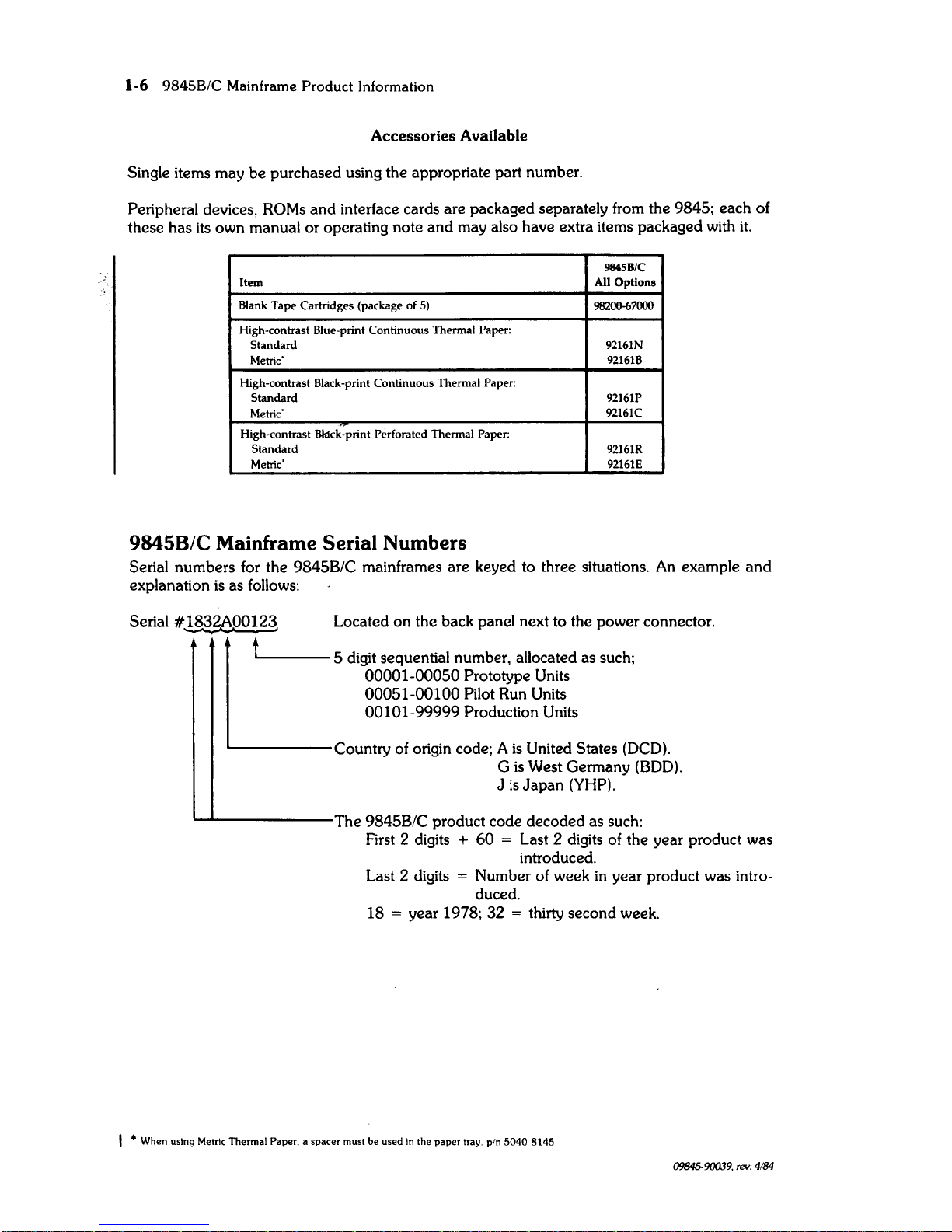
Accessories Available
Single items may be purchased using the appropriate part number.
Peripheral devices,
ROMs
and
interface cards are packaged separately from the 9845; each of
these has its own manual
or
operating note
and
may also have extra items packaged with
it.
984SB/C
Item
All Options
Blank
Tape
Cartridges (package of
5)
98200-67000
High-contrast Blue-print
Continuous
Thermal Paper:
Standard
92161N
Metric'
92161B
High-contrast Black-print
Continuous
Thermal Paper:
Standard
92161P
Metric'
92161C
High-contrast
Bklck-print Perforated Thermal Paper:
Standard
92161R
Metric'
92161E
9845B/C
Mainframe Serial Numbers
Serial numbers for the 9845B/C mainframes are keyed to three situations.
An
example
and
explanation
is
as follows:
Serial
#~b.oOl~
Located
on
the back panel next to the power connector.
L=
5 digit sequential number, allocated as such;
00001-00050 Prototype Units
00051-00100 Pilot Run Units
00101-99999 Production Units
Country of origin code; A
is
United States (DCD).
G
is
West Germany
(BOD).
J
is
Japan
(YHP).
'--L...------The
9845B/C product code decoded as such:
First 2 digits
+
60
= Last 2 digits of the year product was
introduced.
Last 2 digits
= Number of week
in
year product was intro-
duced.
18
= year 1978; 32 = thirty second week.
I * When using Metric Thermal Paper. a spacer must
be
used in the
paper
tray.
pin
5040-8145
09845-90039,
rev:
4184
9845B/C Mainframe Product Information
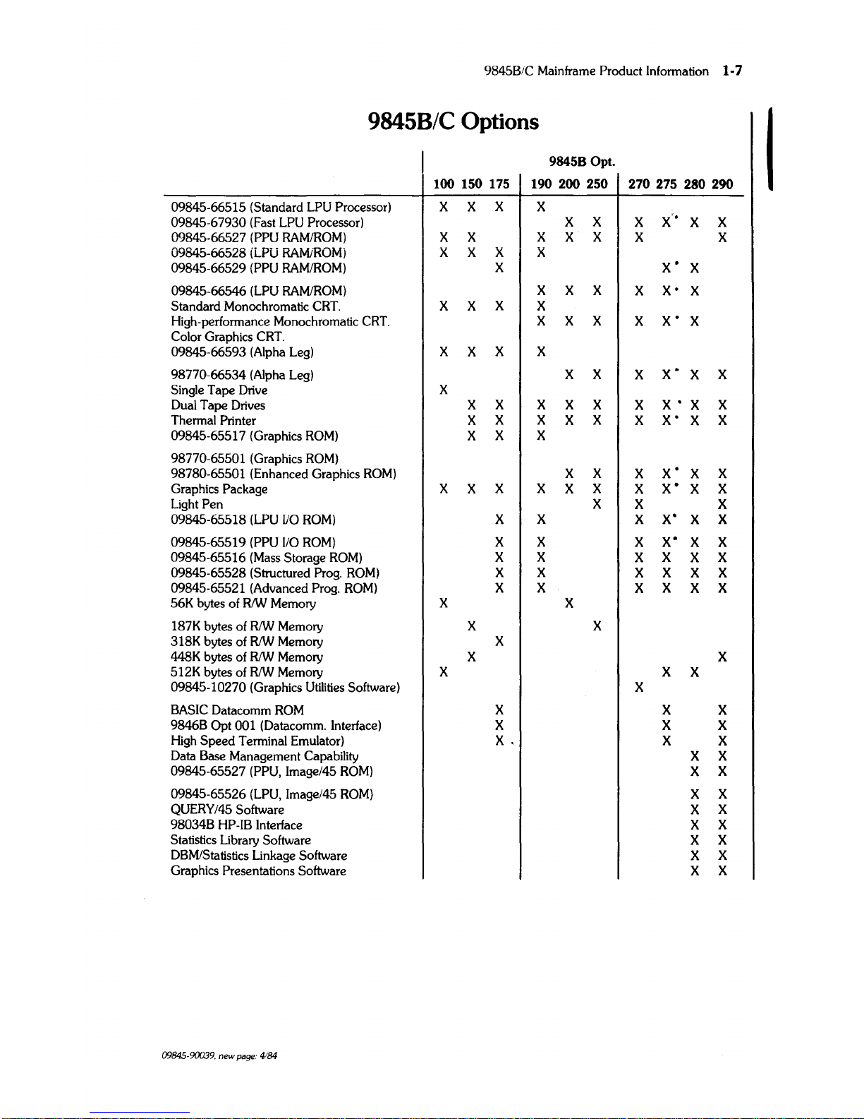
1-7
9845B/C
Options
I
98458 Opt.
100 150 175 190 200 250
270
275 280 290
09845-66515 (Standard LPU
Processor)
X X X X
09845-67930
(Fast
LPU
Processor)
X X
X
X'·
X
X
09845-66527
(PPU
RAM/ROM) X X
X
X
X
X
X
09845-66528 (LPU RAMtROM; X
X X X
09845-66529
(PPU
RAMiROM)
X
X'
X
09845-66546 (LPU RAMiROM) X X X
X
X·
X
Standard Monochromatic
CRT.
X X
X
X
High-performance Monochromatic
CRT.
X X X
X
X'
X
Color
Graphics
CRT.
09845-66593 (Alpha
Leg)
X
X
X X
98770-66534 (Alpha
Leg)
X X
X
X·
X
X
Single
Tape
Drive
X
Dual
Tape
Drives
X X X X X
X
X'X
X
Thermal Printer
X
X X
X
X
X
X'
X
X
09845-65517
(Graphics
ROM)
X
X X
98770-65501
(Graphics
ROM)
98780-65501
(Enhanced
Graphics
ROM)
X
X
X
X'
X X
Graphics
Package
X X
X
X X
X
X
X'
X
X
Light
Pen
X
X X
09845-65518 (LPU
va
ROM)
X X X
X'
X
X
09845-65519
(PPU
110
ROM)
X X
X
x·
X X
09845-65516
(Mass
Storage
ROM)
X X
X
X
X X
09845-65528 (Structured
Prog.
ROM)
X X
X X X X
09845-65521
(Advanced
Prog.
ROM)
X X
X
X
X X
56K
bytes
of
RIW
Memory X
X
187K
bytes
of
RIW
Memory
X
X
318K
bytes
of
RIW
Memory X
448K
bytes
of RIW Memory
X X
512K
bytes
of
RIW
Memory X X
X
09845-10270
(Graphics
Utilities
Software)
X
BASIC
Datacomm
ROM
X
X X
9846B Opt
001
(Datacomm.
Interface)
X X X
High
Speed
Terminal Emulator)
X.
X X
Data
Base
Management Capability
X X
09845-65527
(PPU,
Image/45
ROM)
X
X
09845-65526
(LPU,
Image/45
ROM)
X X
QUERY/45 Software
X
X
98034B HP-IB
Interface
X
X
Statistics
Library Software
X X
DBM/Statistics
Linkage Software
X
X
Graphics
Presentations
Software
X
X
09845·90039,
new
page:
4184

1-8
9845B/C Mainframe Product Information
9845C
Opt.
100
150 190
200 250 270
275 280 290
09845-66515 (Standard
LPU
Processor)
X
X
X
09845-67930 (Fast
LPU
Processor)
X X X
X
X
X
09845-66527 (PPU RAMlROM)
X
X
X
X
X X X
09845-66528 (LPU RAMlROM)
X
X X
09845-66529 (PPU RAMIROM)
X
X
09845-66546 (LPU RAMlROM)
X
X
X X X
X
Standard Monochromatic CRT.
High-performance Monochromatic CRT.
Color Graphics CRT.
X
X X X
X X X X
X
09845-66593 (Alpha Leg)
98770-66534 (Alpha Leg)
X X X
X
X
X
X X X
Single Tape Drive
Dual Tape Drives
X
X X
X
X X X
X
X
Thermal
Printer
X
X
X
X
X X X X
X
09845-65517 (Graphics ROM)
98770-65501
(Graphics ROM)
X
X X
98780-65501 (Enhanced Graphics ROM)
X
X X X X
X
Graphics
Package
X
X X X
X
X
X X
X
Light Pen
X
X
X X
X
09845-65518 (LPU
110
ROM)
X
X
X X
X
09845-65519 (PPU
110
ROM)
X
X
X X
X
09845-65516 (Mass Storage ROM)
X
X
X X
X
09845-65528 (Structured Prog. ROM)
X
X
X
X
X
09845-65521 (Advanced Prog. ROM)
X
X X X
X
56K
bytes
of
RIW
Memory
X
X
187K
bytes
of
RIW Memory
X
X
318K
bytes
of
RIW Memory
X
448K bytes
of
RIW Memory
X
X
512K bytes
of
RIW
Memory
X
X
09845-10270 (Graphics Utilities Software)
X
BASIC Datacomm
ROM
X X
9846B
Opt
001 (Datacomm. Interface)
X X
High Speed Terminal Emulator)
X X
Data
Base
Management Capability
X
X
09845-65527 (PPU, Image/45 ROM)
X
X
09845-65526 (LPU, Image/45 ROM)
X
X
QUERY/45 Software
X
X
98034B HP-IB Interface
X
X
Statistics Library Software
X
X
DBMIStatistics Linkage Software
X
X
Graphics Presentations Software
X
X
09845-90039. new
page:
4/84
2-1
9845B/C
IICM~~I
I-...--_E_n_Vl_-r_O-nm-e-n-lallI-_ost-all_a-ti--
o_nlP_M_-----'"
2 I
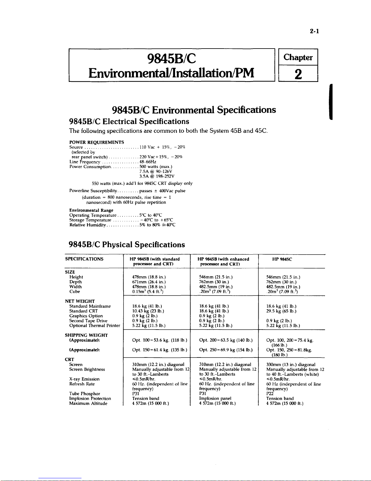
9845B/C Environmental Specifications
9845B/C
Electrical
Specifications
The following specifications are common to both the System
458
and
45C.
POWER REQUIREMENTS
Source
(selected by
rear
panel
switch) .
Line Frequency .
Power
Consumption
...
.110 Vac + 15%,
-20%
.
......
220Vac+15%,
-20%
..48--66Hz
..500
watts
(max.)
7.5A
@
90--126V
3.5A @ 198--252V
550
watts
(max.)
add'i
for 9845C CRT display only
Power
line Susceptibility
..........
passes
± 400Vac
pulse
(duration
= 800
nanoseconds,
rise time = 1
nanosecond)
with
60Hz
pulse
repetition
Environmental
Range
Operating
Temperature.
Storage
Temperature
..
Relative
Humidity
.....
.
.
5°C
to 40°C
.
-40"C
to +65°C
......
5%
to 80%
(cL4O°C
9845B/C
Physical
Specifications
SPECIFICATIONS
HP
98458
(with
standard
processor
and
CRT)
SIZE
Height
478mm (18.8 in.)
Depth
671mm (26.4 in.)
Width
478mm (18.8 in.)
Cube
0.15m3 (5.4 ft.
3
)
NET
WEIGHT
Standard
Mainframe
18.6 kg
(41
lb.)
Standard
CRT
10.43
kg
(23
lb.)
Graphics
Option
0.9 kg
(2
lb.)
Second
Tape
Drive
0.9 kg
(2
lb.)
Optional
Thermal
Printer
5.22 kg (11.5 lb.)
SHIPPING
WEIGHT
(Approximate):
Opt.
100=53.6
kg. (118 lb.)
(Approximate):
Opt.
150=61.4
kg. (135 lb.)
CRT
Screen 310mm (12.2 in.) diagonal
Screen Brightness Manually adjustable from
12
to 30 ft.-Lamberts
X-ray Emission
,;;;0.5mRlhr.
Refresh Rate 60 Hz.
(independent
of line
frequency)
Tube
Phosphor
P31
Implosion Protection
Tension
band
Maximum
Altitude 4 572m (15000 ft.)
HP
98458 (with
enhanced
HP
9845C
processor
and
CRT)
546mm (21.5 in.) 546mm (21.5 in.)
762mm
(30
in.)
762mm (30 in.)
482.5mm (19 in.)
.20m3 (7.09 ft.
3
)
482.5mm (19 in.)
.20m3 (7.09
ft.
3
)
18.6 kg
(41
lb.)
18.6 kg
(41
lb.)
18.6 kg
(41
lb.)
29.5
kg
(65 lb.)
0.9 kg
(2
lb.)
0.9 kg
(2
lb.) 0.9 kg
(2
lb.)
5.22 kg (11.5 lb.)
5.22
kg
(11.5 lb.)
Opt.
200=63.5 kg (140 lb.)
Opt.
100, 200 = 75.4 kg.
(166 lb.)
Opt.
250=69.9
kg (154 lb.)
Opt.
150, 250 = 81.8kg.
(180 lb.)
310mm (12.2 in.) diagonal 330mm (13 in.)
diagonal
Manually adjustable from
12
Manually
adjustable
from
12
to
30
ft.-Lamberts
to
40
ft.-Lamberts
(white)
,;;;0.5mRlhr.
,;;;0.5mRlhr.
60 Hz.
(independent
of line
60
Hz
(independent
of line
frequency) frequency)
P31
P22
Implosion
panel
Tension
band
4 572m (15000 ft.)
4 572m (15
000 ft.)
I
2-2
9845B/C Environmental, Installation,
and
Preventive Maintenance Requirements
9845B/C
Installation
Introduction
The following pages cover installation, maintenance, and system testing for the HP 9845B
and
HP
9845C
Desktop Computers. Where similar, the computers are referred to as the "System
45"
or
the
"9845".
Any differences between computers
or
models are noted when necessary.
The following table shows the configuration
for the model numbers which are referred to.
Standard
Processor
Enhanced Processor
Monochromatic
CRT
(98750A)
98458
Model 100
Monochromatic CRT
With Enhanced Graphics
(98780A)
98458 Model 200
Color CRT
(98770A)
9845C Model 100
9845C Model
200
There are other models which are based
on
the model numbers
in
the previous table. The
9845B Model
150, for instance,
is
a 9845B Model 100 with a thermal printer, two tape drives,
graphics,
and
187
K-bytes of read/write memory. For simplicity, this manual refers to Models
100
and
200
only.
If
you have a 9845B Model 150, just remember that your computer
is
referred to as the 9845B Model 100
in
this manual.
Table Mounting
The System
45
mainframe can
be
attached to a table top by replacing each foot with an
internally threaded device
and
bolting up through the table top. Bolting the main frame to a
desk which has a lockable drawer secures the computer from theft. Care must be taken
in
laying
out the bolt holes so that the front edge of the computer overhangs the edge of the table top.
This ensures that the air filters can
still
be removed and cleaned.
The computer can
be
secured to the top of a table or desk
in
the following manner:
•
Drill
four holes in the top surface of a table to accommodate 5/16-24 NF-2A screws
according to the following diagram.
• Replace the four rubber feet attached to the bottom of the computer with the four hexagonal spacers supplied with the Table Mounting Accessory
(P/N 09845-61201), using the
6-19X.
438
Pan Head, Pozidrive, Plastite screws, also supplied.
• Attach the computer to the table top, using four 5/16-24 NF-2A machine screws that are
3/8 inch longer than the thickness of the table top. The hexagonal spacers should
be
held
with a wrench while these screws are tightened to prevent stripping the smaller screws out
of the plastic base.
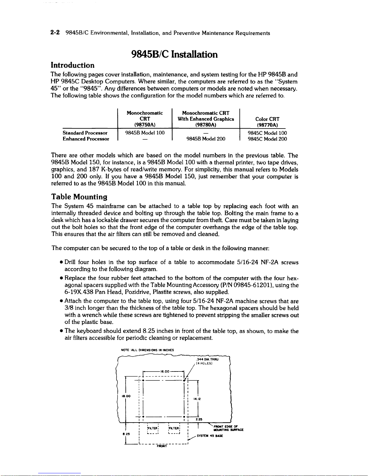
• The keyboard should extend
8.25
inches
in
front of the table top, as shown, to make the
air filters accessible for periodic cleaning
or
replacement.
NOTE:
ALL
OIMENSIONS
IN
INCHES
1.25
~
______________
1
FRONT
9845B/C Environmental, Installation,
and
Preventive
Maintenance
Requirements
2-3
Installing
the
CRT
The System
45
comes equipped with a CRT (Cathode Ray Tube) display. The eight keys
directly below the CRT screen on the
98458
Model
200
and the
9845C
are called softkeys. The
"CRT pull-out cards" (under the CRTj serve as a handy reference for operating the computer.
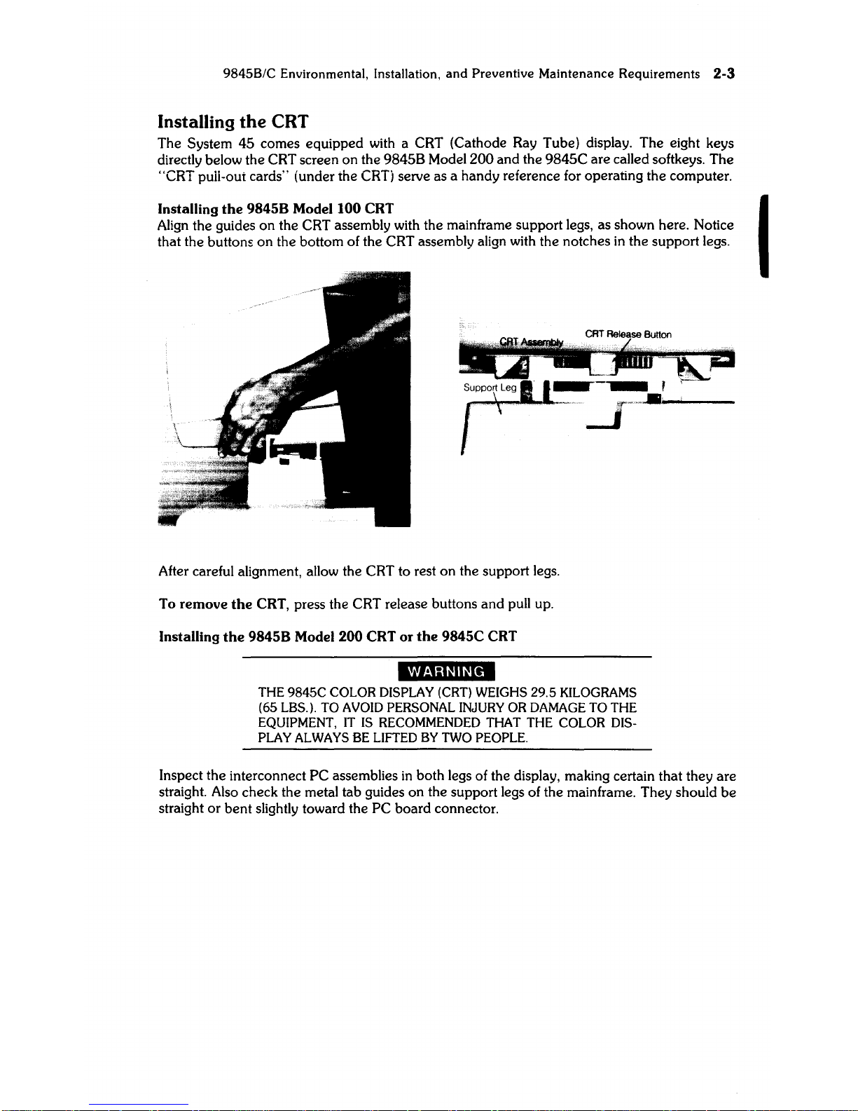
Installing the
98458
Model 100
CRT
I
Align
the guides on the CRT assembly with the mainframe support legs, as shown here. Notice
that the buttons on the bottom of the CRT assembly align with the notches
in
the support legs.
After careful alignment, allow the CRT to rest on the support legs.
To remove the CRT, press the CRT release buttons and pull up.
Installing the
98458
Model 200
CRT
or the 9845C
CRT
'i"S;I§"'.
THE
9845C
COLOR
DISPLAY (CRT) WEIGHS
29.5
KILOGRAMS
(65 LBS.).
TO
AVOID PERSONAL INJURY
OR
DAMAGE
TO
THE
EQUIPMENT,
IT
IS
RECOMMENDED THAT THE
COLOR
DIS-
PLAY
ALWAYS BE LIFTED
BY
TWO PEOPLE.
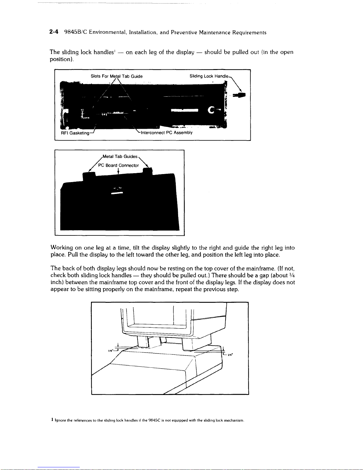
Inspect the interconnect PC assemblies
in
both legs of the display, making certain that they are
straight. Also check the metal tab gUides on the support legs of the mainframe. They should
be
straight
or
bent slightly toward the PC board connector.
2-4
9845B/C
Environmental,
Installation,
and
Preventive
Maintenance
Requirements
The sliding lock handles! -
on
each leg of the display - should be pulled out
(in
the open
position).
Working
on
one
leg at a time, tilt the display slightly to the right
and
gUide
the right leg into
place. Pull the display to the left toward the other leg, and position the left leg into place.
The back of both display legs should now
be
resting on the top cover of the mainframe. (If not,
check both sliding lock handles - they should
be
pulled out.) There should
be
a gap (about %
inch) between the mainframe top cover and the front of the display legs. If the display does not
appear
to
be
sitting properly
on
the mainframe, repeat the previous step.
v."
1 Ignore
the
references
to
the
sliding lock
handles
if
the
9845C
is
not
equipped
with
the
sliding lock
mechanism

984SB/C
Environmental, Installation.
and
Preventive Maintenance
Requirements
2-5
With
the display sitting level, push down
firmly
on
the top front of the display. This compresses
the
RFI
gasketing
and
ensures proper contact with the mainframe.
Now push the sliding lock handles in, to secure the CRT to the mainframe.
To remove
the
CRT, pull the sliding lock handles out and
lift
the CRT straight up. (Remember
that two people are needed to
lift
the color display.)
CRT Intensity
Once the System
45
has been set up
and
is
operating, CRT brightness
is
controlled by a small
dial underneath the CRT.
It
is
located on the right-hand side of the
98458
Model
100
and
on
the left-hand side of the
98458
Model
200
and
the 9845C.
Note
Hewlett-Packard products which use Cathode Ray Tubes are designed to limit X-radiation levels to values of
0.5 mR/hour1 or below
at
Scm distance. This level has been established by the United States
Bureau of Radiological Health and conforms to similar international
reqUirements.
All
measurements are made using equipment that
is
VDE
certified,
and
are conducted with the equipment operating
unner normal conditions as well as worst case maladjustment.
1
mR/hour:
MilIi-Roentgen
per
hour
I
2-6
9845B/C
Environmental, Installation,
and
Preventive Maintenance Requirements
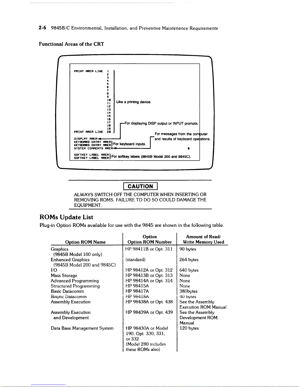
Functional Areas of
the
CRT
PRINT
AREA
LINE
I
2
3
4
5
6
7
B
9
:~
Like a printing device.
12
13
14
15
16
=-iU
:~
For displaying DISP output or INPUT prompts.
19
PRINT
AREA
LINE
211
For messages from the co uter
DISPLAY
AREA
and results of keyboard ope ations.
~~~=~
~:~:~
==}
For keyboard inputs.
SYSTEM
COMMENTS
ARE~--------I
~:~~~~
t=:t
:~=}
For softkey labels (98458 Model 200 and 9845C).
CAUTION
ALWAYS
SWITCH OFF THE COMPUTER WHEN INSERTING OR
REMOVING ROMS.
FAILURE
TO
DO
SO COULD
DAMAGE
THE
EQUIPMENT.
ROMs
Update
List
Plug-in
Option
ROMs
available for
use
with
the
9845
are
shown
in
the
following table.
Option Amount of Read/
Option
ROM
Name
Option ROM
Number
Write Memory Used
Graphics
HP 98411B or Opt. 311
90
bytes
(9845B Model
100
only)
Enhanced Graphics
(standard)
264
bytes
(9845B Model
200
and
9845C)
110
HP 98412A or Opt. 312 640 bytes
Mass Storage
HP 98413B or Opt. 313 None
Advanced Programming
HP 98414A or Opt.
314
None
Structured Programming
HP 98415A None
Basic Datacomm
HP 98417A 380bytes
Bisync Datacomm HP 98418A
40
bytes
Assembly Execution
HP 98438A or Opt. 438
See
the Assembly
Execution
ROM
Manual
Assembly Execution
HP 98439A or Opt. 439
See
the Assembly
and
Development Development
ROM
Manual
Data Base Management System
HP 98430A or Model
120 bytes
190, Opt.
330,331,
or 332
(Model
280 includes
these
ROMs
also)
9845B/C Environmental, Installation,
and
Preventive Maintenance Requirements
2-7
The Option ROM Drawers
The
9845
has two
ROM
drawers which contain the
ROMs.
They are located on each side of the
machine at the base of the dark stripe.
The
ROMs
that belong
in
the left-hand drawer have green labels,
and
those that belong in the
right-hand drawer have black labels.
Since
it
is
important that each
ROM
be
inserted in the
proper drawer, the drawers are designed to prevent inserting a
ROM
in
the wrong drawer.
The labels on the drawers
and
the
ROMs
have symbols on them: a circle, square,
or
triangle.
Use these symbols as a guide
for
matching
ROMs
to the appropriate slots.
· °
ROMs
can go
in
° or D slots.
• D
ROMs
must go
in
D slots.
• ~ ROMs must go
in ~ slots.
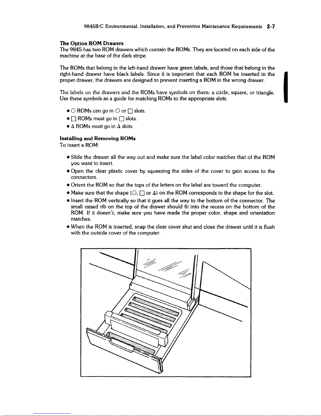
Installing
and
Removing ROMs
To insert a
ROM:
• Slide the drawer
aU
the way out
and
make sure the label color matches that of the
ROM
you want to insert.
• Open the clear plastic cover by squeezing the sides of the cover to gain access to the
connectors.
• Orient the
ROM
so that the tops of the letters on the label are toward the computer.
• Make sure that the shape
(0,
D or
~)
on
the
ROM
corresponds to the shape for the slot.
• Insert the
ROM
verticaUy so that
it
goes
aU
the way to the bottom of the connector. The
smaU
raised rib on the top of the drawer should
fit
into the recess on the bottom of the
ROM.
If
it
doesn't, make sure you have made the proper color, shape and orientation
matches.
• When the
ROM
is
inserted, snap the clear cover shut
and
close the drawer until
it
is
flush
with the outside cover of the computer.
I
2-8
9845B/C
Environmental,
Installation,
and
Preventive
Maintenance
Requirements
To remove a
ROM:
• Turn the power switch
off.
• Slide
out
and
open the proper drawer.
• Gently pull the
ROM
straight up.
• Close the cover
and
slide the drawer
in.
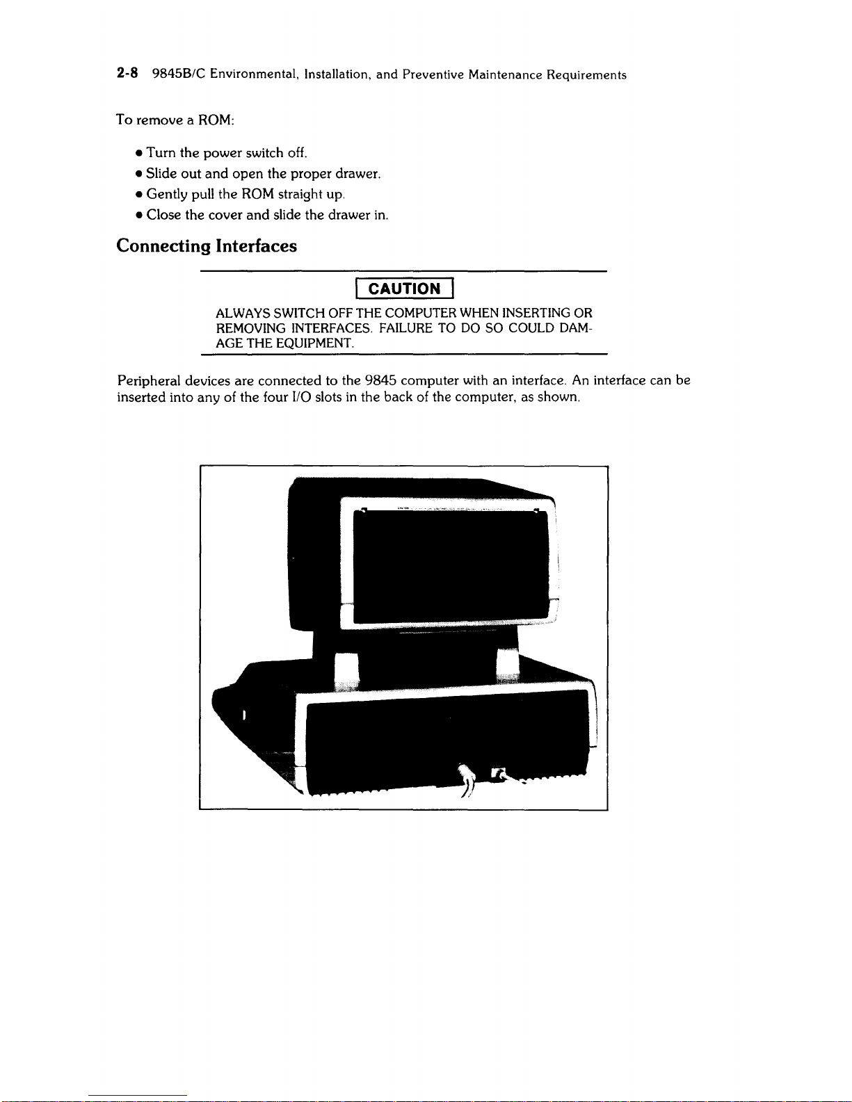
Connecting Interfaces
CAUTION
ALWAYS SWITCH OFF
THE
COMPUTER WHEN INSERTING OR
REMOVING
INTERFACES. FAILURE TO DO
SO
COULD DAM-
AGE
THE
EQUIPMENT.
Peripheral devices are connected to the 9845 computer with an interface.
An
interface can be
inserted into any of the four
I/O
slots
in
the back of the computer, as shown.
9845B/C Environmental, Installation,
and
Preventive Maintenance Requirements 2-9
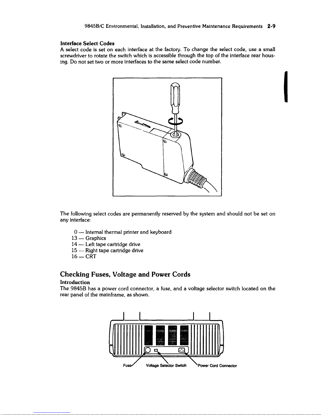
Interface Select Codes
A select code
is
set on each interface at the factory. To change the select code, use a small
screwdriver to rotate the switch which
is
accessible through the top of the interface rear hous-
ing.
Do not set two or more interfaces to the same select code number.
The following select codes are permanently reserved by the system
and
should not
be
set
on
any interface:
o - Internal thermal printer and keyboard
13 - Graphics
14 - Left tape cartridge drive
15 - Right tape cartridge drive
16-CRT
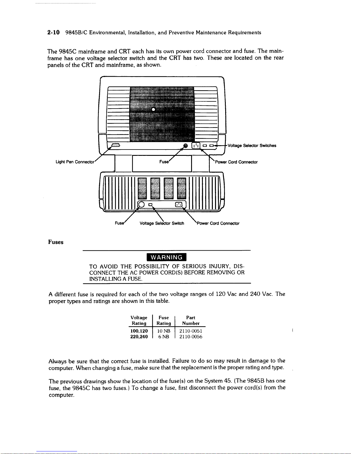
Checking Fuses, Voltage and Power Cords
Introduction
The 9845B has a power cord connector, a fuse,
and
a voltage selector switch located
on
the
rear panel of the mainframe, as shown.
I
2-10 9845B/C
Environmental,
Installation,
and
Preventive Maintenance
Requirements
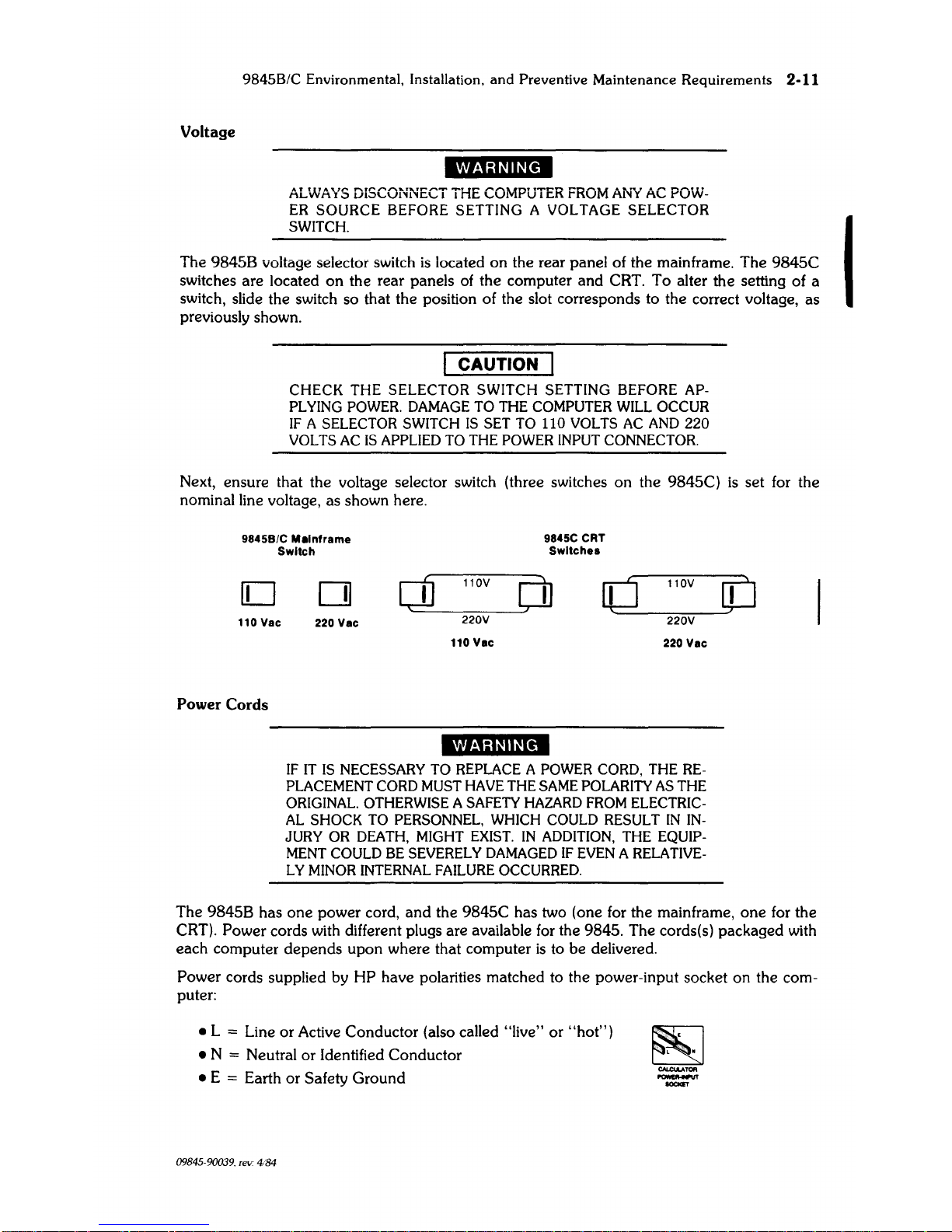
The
9845C
mainframe
and
CRT each has its own power cord connector
and
fuse. The main-
frame has
one
voltage selector switch
and
the CRT has two. These are located on the rear
panels of the CRT
and
mainframe, as shown.
Light Pen
Fuses
)L
__________
~::........:===:5w_-t:
....J1+-+vOHlaae
Selector
Switches
·i"·s;n"~1II
TO
AVOID
THE
POSSIBILITY
OF
SERIOUS
INJURY, DISCONNECT THE AC POWER CORD(S) BEFORE REMOVING OR
INSTALLING A FUSE.
A different fuse
is
required for each of the two voltage ranges of 120 Vac and
240
Vac.
The
proper types
and
ratings are shown
in
this table.
Voltage Fuse
Part
Rating Rating Number
100.120
10
NB
2110-0051
220.240
6
NB
2110-0056
Always be sure that the correct fuse
is
installed. Failure to
do
so may result
in
damage to the
computer. When changing a fuse, make sure that the replacement
is
the proper rating
and
type.
The previous drawings show the location of the fuse(s) on the
System 45. (The
98458
has one
fuse, the
9845C
has two fuses.) To change a fuse,
first
disconnect the power cord(s) from the
computer.
9845B/C Environmental, Installation, and Preventive Maintenance Requirements
2-11
Voltage
11i'!;U"~1CI
ALWAYS
DISCONNECT
THE
COMPUTER
FROM
Ai'fi
AC
POW-
ER
SOURCE BEFORE SETTING A VOLTAGE SELECTOR
SWITCH.
The 9845B voltage selector switch
is
located on the rear panel of the mainframe. The
9845C
switches are located
on
the rear panels of the computer and CRT. To alter the setting of a
switch, slide the switch so that the position of the slot corresponds to the correct voltage, as
previously shown.
CAUTION
CHECK THE SELECTOR SWITCH SETTING BEFORE
AP-
PLYING
POWER.
DAMAGE
TO
THE
COMPUTER
WILL
OCCUR
IF
A SELECTOR SWITCH
IS
SET
TO
110
VOLTS
AC
AND
220
VOLTS
AC
IS
APPLIED
TO
THE
POWER
INPUT
CONNECTOR.
Next, ensure that the voltage selector switch (three switches on the 9845C)
is
set for the
nominal line voltage, as shown here.
98458/C
Mainframe
9845C CRT
Switch
Switches
D
110 Vac
Power Cords
0
[jj
110V
[j]
d
110V
220
Vac
220V
220V
110
Vac
220
Vac
If/"'iU"§1CI
IF
IT
IS
NECESSARY
TO
REPLACE A POWER
CORD,
THE
RE-
PLACEMENT
CORD
MUST
HAVE
THE
SAME
POLARITY
AS
THE
ORIGINAL.
OTHERWISE A
SAFETY
HAZARD
FROM
ELECTRIC-
AL
SHOCK
TO
PERSONNEL,
WHICH
COULD
RESULT
IN
IN-
JURY
OR
DEATH,
MIGHT
EXIST.
IN
ADDITION,
THE
EQUIP-
MENT
COULD
BE
SEVERELY
DAMAGED
IF
EVEN A RELATIVE-
L Y
MINOR
INTERNAL
FAILURE
OCCURRED.
[JJ
The 9845B has
one
power cord,
and
the 9845C has two (one for the mainframe,
one
for the
CRT).
Power cords with different plugs are available
for
the 9845. The cords(s) packaged with
each computer depends upon where that computer
is
to be delivered.
Power cords supplied by HP have polarities matched to the power-input socket on the computer:
• L
:::
Line or Active Conductor (also called "live" or
"hot")
• N
:::
Neutral or Identified Conductor
• E
:::
Earth or Safety Ground
09845-90039. rev. 4184
I
2-12
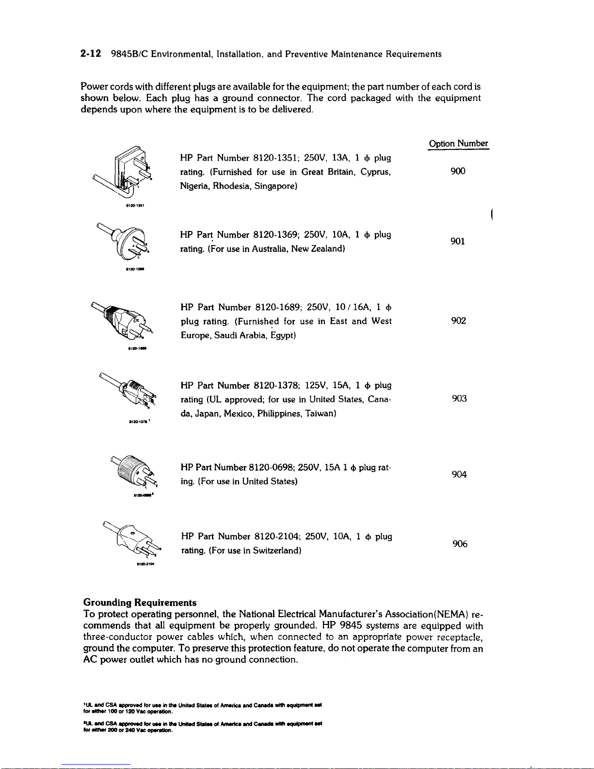
9845B/C Environmental, Installation, and Preventive Maintenance Requirements
Power
cords with different plugs
are
available for the equipment; the part
number
of
each
cord
is
shown
below. Each plug
has a ground
connector.
The
cord packaged with the
equipment
depends
upon
where the
equipment
is
to
be
delivered.
.,»1371
1
~
L •
HP Part Number 8120-1351;
250V,
13A,
1
<I>
plug
rating. (Furnished
for
use
in
Great Britain, Cyprus,
Nigeria,
Rhodesia, Singapore)
HP
Pa~
Number 8120-1369; 250V,
lOA,
1
<I>
plug
rating. (For use
in
Australia,
New
Zealand)
HP Part Number 8120-1689; 250V, 10 /
16A,
1
<I>
plug rating.
(Furnish~d
for use
in
East and West
Europe, Saudi Arabia, Egypt)
HP Part Number 8120-1378;
125V,
15A,
1
<I>
plug
rating
(UL
approved;
for
use
in
United States, Cana-
da, Japan,
Mexico,
Philippines, Taiwan)
HP Part Number 8120-0698; 250V,
15A
1
<I>
plug rat-
ing.
(For use
in
United States)
HP Part Number 8120-2104;
250V,
lOA,
1
<I>
plug
rating.
(For
use
in
Switzerland)
Grounding
Requirements
Option
Number
900
901
902
903
904
906
To
protect
operating personnel, the National Electrical Manufacturer's Association(NEMA) re-
commends
that all
equipment
be
properly grounded. HP
9845
systems
are
equipped
with
three-conductor
power
cables which, when connected to
an
appropriate
power
receptacle,
ground
the
computer.
To
preserve this protection feature,
do
not
operate
the
computer
from
an
AC
power
outlet which
has
no
ground
connection.
'UL
and
CSA
~ved
lor
....
in
the
United
S_
01
America
and
c-da
wtth equipment
lei
lor
either
100
or
120 Vee operellon.
OUt.
and
CSA
~
lor
...
In
theUnllecl
Statea
01
America
and
c-da
with
equIpnWIt
eel
lor either
200
or
240
Vee oper8IIon.
9845B/C
Environmental, Installation, and Preventive Maintenance Requirements
2·13
FCC
Radio Frequency Interference Statement
I FEDERAL
COMMUNICATIONS
COMMISSION
I
RADIO
FREQUENCY iNTERFERENCE I
STATEMENT (U.S.A. ONLY)
I
The Federal Communications Commission
(in
Subpart
J of Part 15. Docket
20780)
has specified that the following I
notice
be
brought to the attention of the users of this product.
I Warning: This equipment generates. uses.
and
can radiate radio frequency energy ann
if
not installed
and
used
in
I
accordance with the instructions manual. may cause interference to radio communications.
As
temporarily permitted by
regulation
it
has not
been
tested for compliance with the limits
for
a Class A computing device pursuant to
Subpart
J of
Part 15 of FCC Rules. which are designed to provide reasonable protection against such interference. Operation of this
equipment
in
a residential area
is
likely to cause interference
in
which case the user at his own expense
will
be
required to
take whatever measures may
be
required to correct the interference.
Initiating Power
Once the computer
is
set up properly,
it
is
ready to turn on. Before you do, here are some
things to check:
•
Is
the proper type of fuse installed?
•
Is
the proper voltage set?
• Are the ROMs installed?
• Are the interfaces
and
peripherals connected?
Next connect the power cord (two on the 9845C) to the power input connector
on
the
rear
panel of the mainframe (and CRT - 9845C).
Plug the other
end
of the cord into
an
AC
power
outlet.
CAUTION
SHOULD
A SINGLE, BRIGHT, HORIZONTAL LINE APPEAR
ACROSS
THE CENTER
OF
THE CRT, IMMEDIATELY SWITCH
THE
COMPUTER
OFF
TO AVOID DAMAGE.
Now that
the
system
is
set up, set the power switch on the right side of the machine to the "1"
position to turn
it
on.
Set
the CRT intensity using the knob under the front of the CRT.
Loading Printer Paper
The internal printer
is
an 80-character line printer used for hardcopy output. Refer to the
section entitled
"Accessories Supplied" for part numbers of the types of paper.
CAUTION
HP
SUPPLIED
THERMAL
PAPER IS
FORMULATED
SPE-
CIFICALL Y TO WORK WITH THE SYSTEM 45 INTERNAL PRIN-
TER.
THERMAL PAPER FROM OTHER SOURCES MAY
OR
MAY
NOT WORK
WITH THE INTERNAL PRINTER AND, THEREFORE,
HP
IS
NOT RESPONSIBLE
FOR
DAMAGES CAUSED BY USING
NON-HP
PAPER.
2-14 9845B/C Environmental, Installation, and Preventive Maintenance Requirements
The average
life
of the internal thermal printhead
is
about 50,000 feet of paper, or about
250
rolls.
Note
If
you
want
to
use
Metric
paper
in
the thermal printer, the
Metric
Paper Spacer (PIN 5040-8145)
must
be
installed
in
the
paper
hol-
der,
on
the right-hand
side.
Two keys are used to control the printer paper. The PAPER
ADVANCE
key advances the paper
until the key
is
released. The TOP OF
FORM
key advances the paper past perforations to the
top margin (approximately 1.25 cm, or
1f2
inch, below the perforations). If the paper
is
not
perforated,
it
is
advanced
30.5
cm (12 inches).
Printer
paper
is
loaded using the following procedure.
• Make sure the computer
is
switched
ON.
•
Lift
or
remove the access cover on the top of the printer by pushing down on the raised
surface at the rear of the door. The door can be removed by lifting up
and
pulling
it
toward
you.
• Remove
and
discard the paper core of any previous
roll.
If the remaining
roll
of
paper
is
small
and
a new roll
is
to be installed, remove the old
roll.
To do this, first unroll
and
lift
the
old roll upward. Then tear the paper off using the paper guide.
• If any
paper
remains
in
the printer mechanism, remove
it
by pressing the PAPER
AD-
VANCE key until the paper
is
completely out.
• Remove the first layer of paper from the new
roll.
Be sure the paper has a cleanly torn
or
cut edge. Fold the corners
in
to form a point.
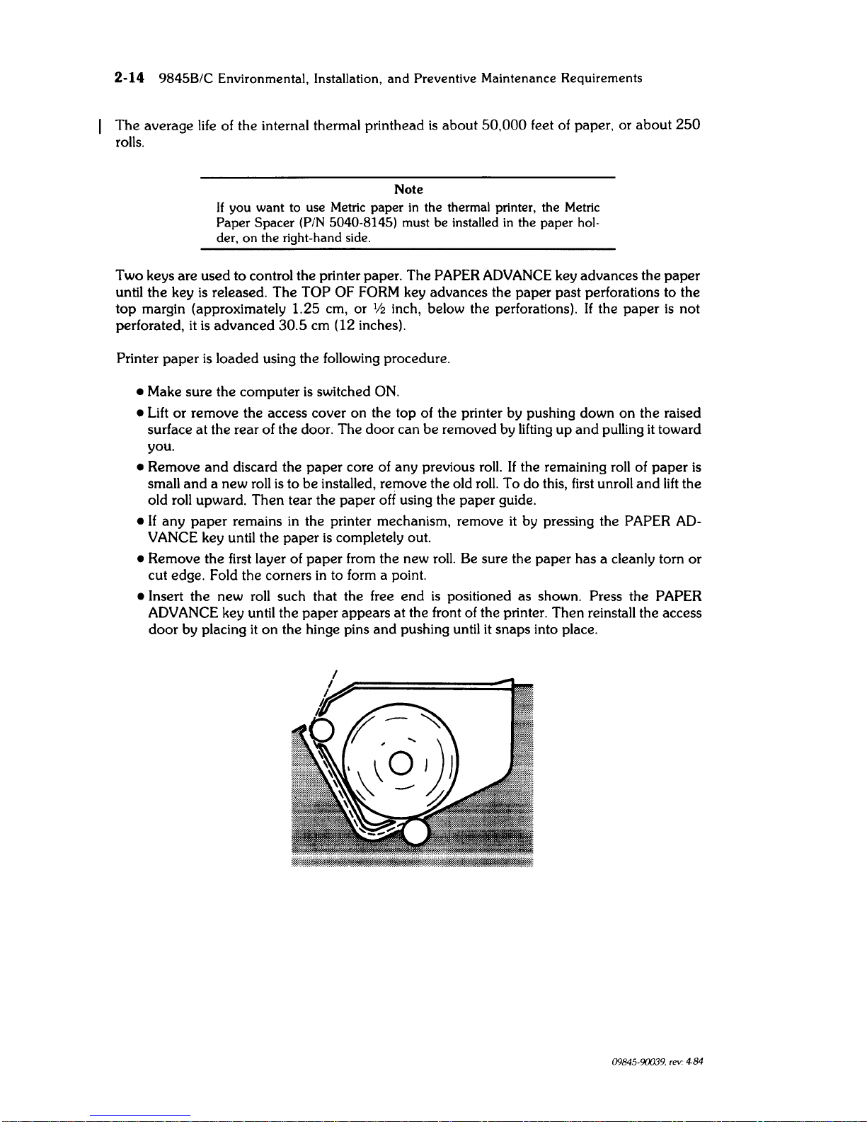
• Insert the new roll such that the free
end
is
positioned as shown. Press the PAPER
ADVANCE
key until the paper appears at the front of the printer. Then reinstall the access
door by placing
it
on
the hinge pins
and
pushing until
it
snaps into place.
09845-90039. rev: 4,84
9845B/C
Environmental. Installation.
and
Preventive
Maintenance
Requirements
2·15
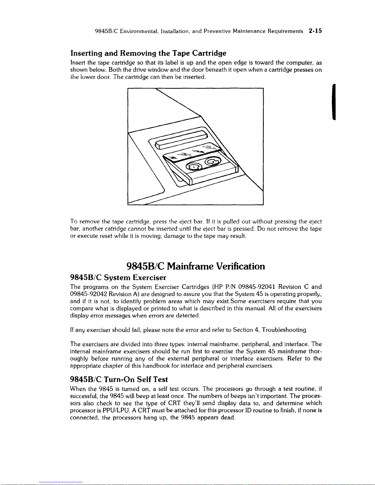
Inserting and Removing
the
Tape Cartridge
Insert the tape cartridge so that its label
is
up
and
the
open
edge
is
toward the computer, as
shown below. Both the drive window and the door beneath
it
open
when a cartridge presses
on
ihe iower door. The cartridge can then be inserted.
To remove the tape cartridge. press the eject bar.
If
it
is
pulled
out
without pressing the eject
bar. another catridge
cannot
be inserted until the eject bar
is
pressed. Do not remove the tape
or execute reset while
it
is
moving; damage to the tape may result.
9845B/C Mainframe Verification
9845B/C
System
Exerciser
The programs
on
the System Exerciser Cartridges (HP PIN 09845-92041 Revision C
and
09845-92042
Revision
A)
are designed to assure you that the System
45
is
operating properly,
and
if
it
is
not, to identify problem areas which may exist.Some exercisers require that you
compare what
is
displayed
or
printed to what
is
described
in
this manual.
All
of the exercisers
display error messages when errors are detected.
If any exerciser should
fail,
please note the error
and
refer to Section 4, Troubleshooting.
The exercisers are divided into three types: internal mainframe. peripheral,
and
interface.
The
internal mainframe exercisers should be run first to exercise the System
45
mainframe thoroughly before running any of the external peripheral or interface exercisers. Refer to the
appropriate chapter
of
this handbook for interface
and
peripheral exercisers.
9845B/C
Turn-On
Self
Test
When the
9845
is
turned on, a self test occurs. The processors go through a test routine,
if
successful, the
9845
will
beep
at least once. The numbers of beeps isn't important.
The
proces-
sors also check to see the type of CRT they'll
send
display data to,
and
determine which
processor
is
PPU/LPU. A CRT must be attached for this processor
10
routine to finish,
if
none
is
connected, the processors hang up, the
9845
appears dead.
I
2-16 9845B/C Environmental, Installation,
and
Preventive Maintenance Requirements
Next,
RWM
is
tested to ensure at least 16K bytes exists
in
block 0,
and
tests graphics
RWM
if
graphics
is
installed. The graphics raster may be seen flashing different patterns during the
graphics
RWM
test, followed by "MEMORY TEST
IN
PROGRESS"
on
the display. Normally,
the CRT circuits may not
be
warmed up enough for the graphics
RWM
tests to be seen. Should
errors
be
trapped
during the
RWM
tests, the CRT should display "PART OF MEMORY FAILED
SELF-TEST".
The
amount
of
RWM
that's lost can be determined by executing LIST
and
comparing available
RWM
with the
amount
of
RWM
the
9845
should have.
When the turn-on tests are successfully completed, the display should read:
"9845
READY
FOR USE". If AUTOST
had
been
latched,
and
a tape inserted in T15, the tape should rewind
and
load the AUTOST program
and
run
it.
Refer to the
9845B/C
Mainframe Troubleshooting, Section 4,
if
this test has errors
or
fails.
Exerciser Starting Procedure
Before starting, use the following checklist to ensure that the 9845B/C
is
ready for testing.
• Switch
power
off.
•
On
the back panel, check to ensure that the line voltage selector switches are set,
and
that
the correct fuse(s)
is
(are) installed.
• Verify that
the
ROMs
and
interfaces are properly installed.
Latch the
AUTOST key
on
the computer. Begin by inserting System Exerciser Cartridge
#1
in
the right-hand
tape
drive so that the cartridge label faces up
and
out. Switch on power to the
System 45,
and
the computer should load
and
run the supervisory exerciser program. If this
does
not happen,
or
if
a blinking cursor does not appear on the CRT within
about
20
seconds
after turn-on
and
cannot
be
obtained by pressing CONTROL STOP, refer to Section 4, Troub-
leshooting.
The supervisory exerciser program can also be loaded by typing
LOAD
11
AUTOST:
T
15
11
and
pressing EXECUTE.
When the supervisory exerciser program begins to run, the following information
is
displayed:
88455/C
SYSTEM
EXERCISER
Do
YOU
want
PRINTED
output
(Y,N)?
Answer Y for yes or N for no. and press CONT. If you want the printout to
appear
on the CRT,
answer no.
If you answer yes, you are asked to:
Please
enter
the
PRINTER
select
code
•••
For non-HP-IB printers, enter the interface select code. (Enter 0 for the internal printer.)
If you have an HP-IB printer. answer with the select code
and
the device address entered
together as a three
or
four digit number. The interface select code can be a
one
or
two digit
number
which represents a valid select code. The
deVice
address must be a two digit number.
For example, a 9871A
Printer (HP-IB option only) connected
on
interface 7 with its address set
to 6
is
entered
as
"706".
(Secondary addressing of HP-IB devices
is
not allowed.)
The choices of exercisers for System Exerciser Cartridge # 1 are then printed on the specified
printer (or
the
CRT).
An
asterisk
(*)
appearing before any of the
MAINFRAME
exercisers shows that that particular
option
is
not installed.
Use the
same
procedure to run the exercisers on System Exerciser Cartridge
#2.
Now select
and
run exerciser(s) as explained on the
follOWing
pages.
 Loading...