

Page 1

9840 Tape Drive
Operations Guide
Abstract
This guide describes how to perform routine system operations for the 9840 tape drive
and associated tape libraries on HP NonStop™ servers and Integrity NonStop NS series servers. These tasks include monitoring the operator panel and performing
labeled tape ope rations, backups, and ba sic troub le shootin g. Th is guide al so describe s
installing and configuring the 9840 tape drive for the NonStop NS-series server. It is
written for system operators.
Product Version
N.A.
Supported Release Version Updates (RVUs)
This guide supports G06.11 and all subsequent G-series RVUs and H06.03 and all
subsequent H-series RVUs until otherwise indicated by its replacement publication.
Part Number Published
429596 -002 June 2005
Page 2

Document History
Part Number Product Version Published
429596- 001 N.A. March 20 01
429596- 002 N.A. June 2005
Page 3

9840 Tape Drive
Operations Guide
Glossary Index Examples Figures Tables
What’s New in This Manual vii
Manual Information vii
New and Changed Information vii
About This Manual ix
Notation Conventions ix
1. 9840 Tape Drive Overview
9840 Tape Drive Description 1-1
Fast Data Transfer Rate 1-1
High-Capacity 1-1
Media Durability 1-1
Data Compression 1-1
Performance 1-2
9840 Tape Drive in Tape Libraries 1-2
9840 Tape Cartridge Description 1-2
Where to Find More Information 1-4
2. 9840 Operator Panel
Operator Panel Description 2-1
Operator Panel Switches
Operator Panel LEDs
Operator Panel Display 2-7
2-2
2-5
3. Operating the 9840 Tape Drive
Powering On and Performing an IPL on a Tape Drive 3-1
Performing an IPL on the Tape Drive From the Host 3-1
Checking the Status of Tape Devices 3-2
Using the TSM Service Application
Using the SCF STATUS Command
Starting or Stopping a Tape Drive 3-4
Taking a Tape Drive Online or Offline 3-4
Starting a Tape Device using SCF 3-4
Hewlett-Packard Company—429596-002
3-2
3-2
i
Page 4

Contents
Cleaning the Tape Path 3-8
Performing Tape Cartridge Operations 3-9
Using Labeled Tapes 3-11
Using BACKUP and RESTORE 3-12
4. L700 Tape Library
Stopping a Tape Device using SCF 3-7
To Dry-Clean the Tape Path 3-9
Write-Pro tecting a Tape Cartridge 3-9
Loading a Tape Cartridge 3-9
Unloading a Tape Cartridge 3-10
Reclaiming (Reformat) a Tape Cartridge 3-10
Formatting a Diagnostic Dump Tape 3-11
Enabling or Disabling Labeled-Tape Operations using SCF 3-11
Using the MEDIACOM Utility for Labeled-Tape Operation 3-12
Restoring Tape Files to Disk 3-13
Viewing the Contents of a Tape 3-13
Using the BLOCKSIZE Option 3-13
Using the NOUNLOAD Option 3-13
Using BACKUP and RESTORE with Tape Libraries 3-14
Using Multiple Tape Cartridges 3-14
Where to Find More Information 3-15
4. L700 Tape Library
Operator Panel 4-2
Indicators 4-3
Buttons 4-3
Display Screens 4-3
Operations Overview 4-13
Library Power Switch 4-13
Tape Drive Power Switches 4-14
Operating in the Automated Mode 4-15
Monitoring Status Information 4-16
Entering Cartridges Through the CAP 4-18
Ejecting Cartridges Through the CAP 4-19
Manually Cleaning a Drive 4-20
Reviewing FSC Logs 4-21
Running Diagnostic Tests 4-21
Powering Off the Library 4-24
Operation in Manual Mode 4-24
Opening the Library Front Doors 4-25
9840 Tape Drive Operations Guide —429596-002
ii
Page 5

Contents
Moving the Robot 4-25
A. 9840 Troubleshooting and Recovery
Handling Errors or Indications A-1
Save Fails Error A-1
Fix_CfgErr Error A-1
UnWr xxxx Indication A-2
DumpAgain? Message A-3
Identifying Unrecov erab le Tapes A-3
Forcing a Diagnostic Dump (Reset Drive) A-4
Removing a Stuck Tape Cartridge A-5
Operating a Drive Manually in a Tape Library A-6
Performing a Tape Boot or Tape Load A-6
Performing Processor Memory Dumps to Tape A-6
B. 9840 Menu System
A. 9840 Troubleshooting and Recovery
Using the Menu System B-1
Menu Structure Overview B-1
Examples of Me nu Operations, Reference B-2
Instructions for Menu Operations B-3
Explanation of the Menu Trees B-3
View SCSI Configuration Status B-5
SCSI Configuration Menu B-8
Drive Operations Menu B-14
Tape Bar-Chart Explanation B-17
Examples of Menu Operations B-18
How to enter the Menu system B-18
How to View Drive Configuration of Software Level B-19
How to Save, Abort, or Repeat Configuration Changes B-20
How to Repeat or Exit the Menu System B-20
Example of Menu Selection: SCSI Bus Speed Mode B-21
Example of Menu Selection: Enable/Disable Compression B-22
C. Installing and Configuring the Tape Drive for the NonStop
NS-Series Server
Overview C-1
Installation C-3
Configuration C-8
9840 Tape Drive Operations Guide —429596-002
iii
Page 6

Contents
Safety and Compliance
Index
Examples
Figures
Figure 1-1. The 9840 Tape Cartridge 1-3
Figure 2-1. 9840 Operator Panel 2-1
Figure 4-1. Operator Panel Display, Control, and Indicators 4-2
Figure 4-2. Library Status Screen 4-4
Figure 4-3. Main Menu Screen 4-5
Figure 4-4. FSC Log Screen 4-6
Figure 4-5. CAP Status Screen 4-6
Figure 4-6. Drive Information Menu 4-7
Figure 4-7. Cleaning Informaion Menu 4-8
Safety and Compliance
Figure 4-8. Main Diagnostics Menu 4-9
Figure 4-9. Version Information Menu 4-9
Figure 4-10. Configuration Menu 4-10
Figure 4-11. Library Configuration Menu 4-11
Figure 4-12. Drive Configuration Menu 4-12
Figure 4-13. Display Information Menu 4-12
Figure 4-14. Library Power Switch Location 4-14
Figure 4-15. Drive Power Switch Location 4-15
Figure 4-16. Removing the CAP Magazine 4-19
Figure 4-17. Opening the Access Doors 4-25
Figure 4-18. Extending the Gripper 4-27
Figure 4-19.
Figure 4-20.
Figure A-1. Recovering From a Stuck Cartridge A-5
Figure B-1. Online Menu Structure B-1
Figure B-2. Offline Me nu Structure B-2
Figure B-3. Menu Tree Legend B-4
Figure B-4. View of SCSI Configuration Status Menu B-5
Removing the Cartridge from the Hand 4-28
Loading a Cartridge into the 9840 Tape Drive 4-29
Figure B-5. SCSI Configuration Menu B-8
Figure B-6. Drive Operations Menu B-14
Figure B-7. Tape Bar Chart B-18
Figure C-1. Hardware Configuration C-2
Figure C-2. SCSI Cable C-3
Figure C-3. Front View of the Fibre Channel to SCSI Router C-4
9840 Tape Drive Operations Guide —429596-002
iv
Page 7

Contents
Figure C-4. Rear View of the Fibre Channel to SCSI Router C-4
Figure C-5. Front View of the Tape Drive C-5
Figure C-6. Rear View of the Tape Drive C-6
Figure C-7. View of Two FCSAs at the Rear of the Server C-7
Figure C-8. Rear View of the Fibre Channel to SCSI Router C-8
Tables
Table 1-1. 9840 Cartridge Capacities 1-2
Table 2-1. Operator Panel Switches 2-3
Table 2-2. Operator Panel LEDs 2-5
Table 2-3. Service and Power LEDs 2-6
Table 2-4. Operator Panel Messages 2-7
Table 4-1. Drive Status Messages 4-16
Table 4-2. CAP S ta tus Messages 4-17
Table 4-3. CTL700 Library Drive Diagnostic Tests 4-22
Tables
Table C-1. SCSI Cable Part Numbers and Descriptions C-3
Table C-2. Fiber Cables C-8
9840 Tape Drive Operations Guide —429596-002
v
Page 8

Contents
9840 Tape Drive Operations Guide —429596-002
vi
Page 9

What’s New in This Manual
Manua l In forma ti o n
9840 Tape Drive
Operations Guide
Abstract
This guide describes how to perform routine system operations for the 9840 tape drive
and associated tape libraries on HP NonStop™ servers and Integrity NonStop NS series servers. These tasks include monitoring the operator panel and performing
labeled tape oper ations, b ackups, and basic tro ublesho oting. T his gui de also descr ibes
installing and configuring the 9840 tape drive for the NonStop NS-series server. It is
written for system operators.
Product Version
N.A.
Supported Release Version Updates (RVUs)
This guide supports G06.11 and all subsequent G-series RVUs and H06.03 and all
subsequent H-series RVUs until otherwise indicated by its replacement publication.
Part Numb er Pub l i sh ed
429596- 002 June 2005
Document History
Part Number Product Ve rsion Published
429596- 001 N.A. March 20 01
429596- 002 N.A. June 2005
New and Changed Information
Added Appendix C, Installing and Configuring the Tape Drive for the NonStop NS-
Series Server.
9840 Tape Drive Operations Guide —429596-002
vii
Page 10

What’s New in This Manual
New and Changed Information
9840 Tape Drive Operations Guide —429596-002
viii
Page 11

About This Manual
Notation Conventions
Hypertext Links
Blue underline is used to indicate a hypertext link within text. By clicking a passage of
text with a blue underline, you are taken to the location described. For example:
This requirement is described under Backup DAM Volumes and Physical Disk
Drives on page 3-2.
Change Bar Notation
Change bars are used to indicate substantive differences between this manual and its
preceding version. Change bars are vertical rules placed in the right margin of
changed portions of text, figures, tables, examples, and so on. Change bars highlight
new or revised information. For example:
The message types specified in the REPORT clause are different in the COBO
environment and the Common Run-Time Environment (CRE).
The CRE has many new message types and some new message type codes for
old message types. In the CRE, the message type SYSTEM includes all
messages except LOGICAL-CLOSE and LOGICAL-OPEN.
9840 Tape Drive Operations Guide —429596-002
ix
Page 12

About This Manual
Change Bar Notation
9840 Tape Drive Operations Guide —429596-002
x
Page 13

1 9840 Tape Drive Overview
This section contains:
9840 Tape Drive Description 1-1
9840 Tape Drive in Tape Libraries 1-2
9840 Tape Cartridge Description 1-2
Where to Find More Information 1-4
9840 Tape Drive Description
The 9840 is a small, modular, high performance tape drive designed for NonStop
servers. The 9840 tape drive is used in tape enclosure or tape library configurations
and is compatible with theses tape libraries: the 9310, 9710, 9740, and L700.
The tape drive measures 82.55 mm (3.25 inches) high, 146.05 mm (5.75 inches) wide,
and 381 mm (15 inches) deep. The 9840 featur es a pr opr ieta ry design to provide faster
average access time, higher data rates, higher capacity, and lower costs compared
with similar units in the marketplace.
Fast Data Transfer Rate
Used for unattended backups or archiving, the 9840 tape drive allows the user to
backup a higher data capacity at a higher speed. In a noncompressed mode, the 9840
tape drive has a maximum transfer rate of 10 MB/sec.
High-Capacity
The 9840 tape drive accepts the STK1R data cartridge. When this cartridge is used,
the amount of data stored on the tape can be up to 20 GB (uncompressed).
Media Durability
The STK1R data cartridge can endure 10,000 loads, 6,500 long-length passes, and
80,000 short-length passes, and a minimum shelf life of 10 years, which provides
superior media durability and data reliability.
Data Compression
The 9840 tape drive can write compressed or uncompressed information to a labeled
or unlabeled tape. Compression increases the cartridge capacity (over the
uncompressed format) by two to three times.Writing compressed data on tape means
the tape drive compr esses dat a whene ver possibl e . The specific amou nt of dat a stored
on the tape is not predictable because the amount of compression varies with the type
of data being written. Because of this, the amount of compressed data stored on tape
can vary significantly.
9840 Tape Drive Operations Guide —429596-002
1-1
Page 14

9840 Tape Drive Overv iew
The 9840 tape drive can store up to 60 gigabytes (GB) on a STK1R data cartridge.
Table 1-1. 9840 Cartridge Capacities
Performance
Cartridge Type
STK1R Data
Cartridge
Performance
The 9840 tape drive stores and shares information reliably and quickly. It offers the
speed, capacity, and access demanded by today's storage-intensive applications and
active users. Mainframe-class reliability allows continuous and confident operation.
Utilize space more efficiently by attaching more drives to a new or existing library.
Unrestricted connectivity and adaptability support unlimited growth for open system to
mainframe, Ultra SCSI, Fibre Channel, and ESCON. It fits seamlessly and costeffectively into current StorageTek automated storage solutions.
The 9840 subsystems have these characteristics:
Faster backup and restore operations. Move or retrieve data with simultaneous
•
read or write to each controller transport unit. First access to data averages 8
seconds.
More data storage. Each cartridge holds up to 20 GB uncompressed (60 GB with
•
compression).
9840
(Uncompressed)
20 GB 60 GB
9840
(Compressed)
Easy migration to present and emerging technologies.
•
Flexible. Mix media within an automated library. Attach additional drives to new or
•
existing libraries.
9840 Tape Drive in Tape Libraries
The 9710 ACS Tape Library can house up to ten 9840 tapes drives. The library holds
from 252 to 588 tape cartridges. The robot contained in the 9710 ACS Tape Library is
responsible for loading and unloading the tape cartridges in the tape drives as tapes
are requested by the system.
9840 Tape Cartridge Description
The tape cartridge used by the 9840 tape drive has a 20-gigabyte capacity
(uncompressed). The components are shown in Figure 1-1.
9840 Tape Drive Operations Guide —429596-002
1-2
Page 15
9840 Tape Drive Overv iew
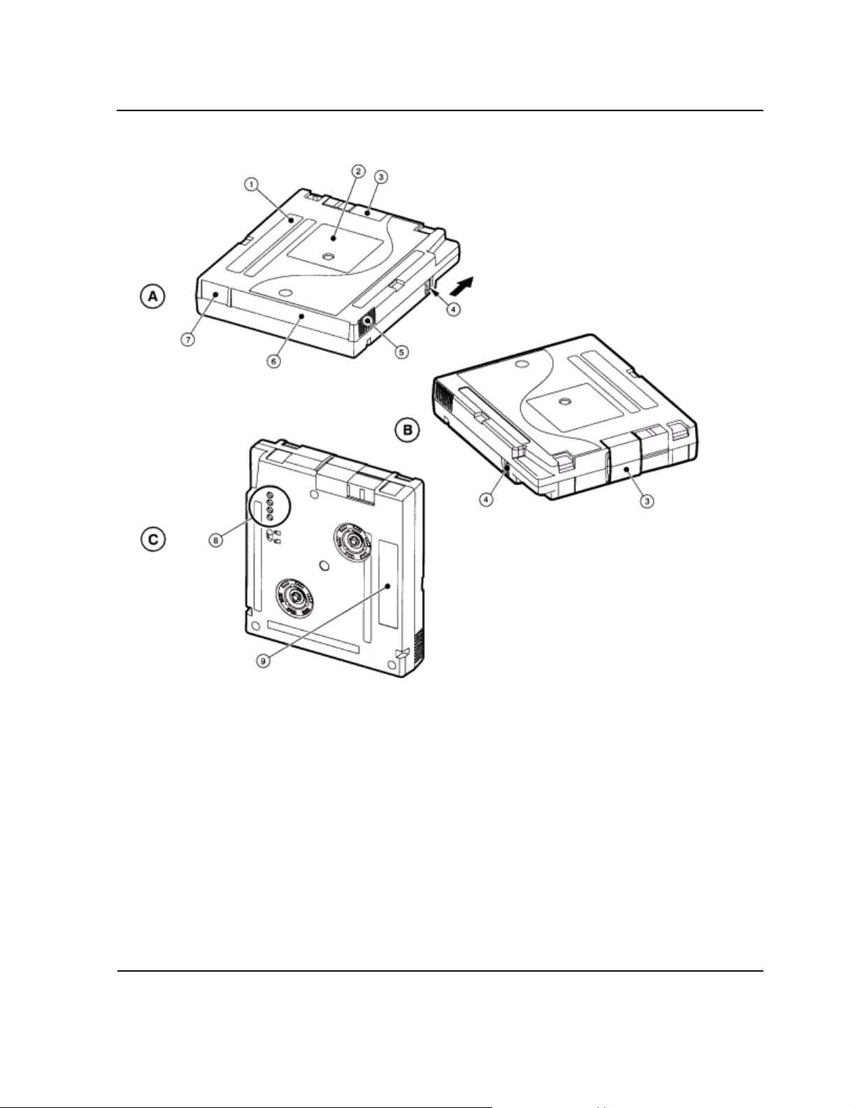
Figure 1-1. The 9840 Tape Cartridge
9840 Tape Cartridge Description
A. Rear view 4. Write protect switch
B. Front view 5. Finger grips
C. Bottom view 6. VOLSER label
1. Manufacturer label 7. Media ID (human or barcode readable)
2. Customer label 8. Media ID (machine readable)
3. Access door 9. Manufacturer part ID
9840 Tape Drive Operations Guide —429596-002
1-3
Page 16

9840 Tape Drive Overv iew
Where to Find More Information
Use this manual in conjunction with these manuals:
Source Manual
HP SCF Reference Manual for the Storage Subsystem
HP S-series Planning and Configuration Guide
HP Guardian User’s Guide
HP Guardian Disk and Tape Utilities Reference Manual
HP 9840 (CT9840FC-3) Installation and User’s Guide for
NonStop Servers
STK 9840 Tape Drive User’s Reference Manual
STK 9840 Tape Drive Product Manual
STK 9840 Tape Drive System Product Manual
Where to Find More Info r mation
STK 9710 ACS Tape Library Operators Guide
9840 Tape Drive Operations Guide —429596-002
1-4
Page 17
2 9840 Operator Panel
This section contains:
Operator Panel Description 2-1
Operator Panel Switches 2-2
Operator Panel LEDs 2-5
Operator Panel Display 2-7
Operator Panel Description
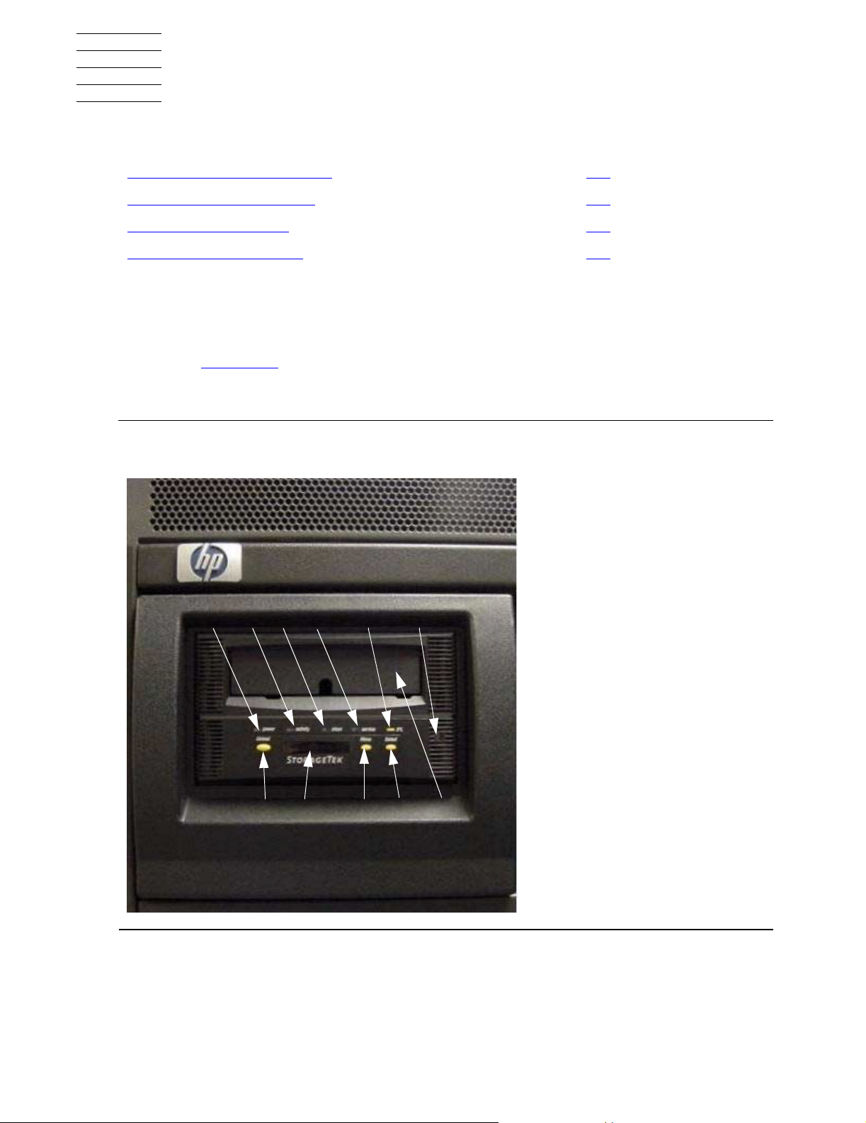
The 9840 operator panel has a ten-digit display, four push-button switches, and four
indicators. Figure 2-1 illustrates the 9840 operator panel.
Figure 2-1. 9840 Operator Panel
1 2 3 4 5 6
7 8 9 10 11
1. Power indicator
2. Activity indicator
3. Clean indicator
9840 Tape Drive Operations Guide —429596-002
2-1
Page 18

9840 Operator Panel
4. Service indicator
5. IPL switch
6. Manual unload device
7. Unload switch
8. Operator display
9. Menu switch
10. Select switch
11. Tape cartridge entry
Operator Panel Switches
Table 2-1 describes the operator panel switches. The Menu and Select switches (9
and 10) are unique to the 9840 design. Together they enable you to obtain information
about the tape drive or to perform special tape operations such as reformatting tapes.
Operator Panel Switches
9840 Tape Drive Operations Guide —429596-002
2-2
Page 19

9840 Operator Panel
Table 2-1. Operator Panel Switches
Control Name Control Description
Operator Panel Switches
Pressing this switch causes the tape to rewind and unload, ending
with the tape ejected and retrievable.
If this switch is pressed during a write operation, the tape drive
attempts to write the remaini ng data before it unloa ds. A displ ay of
“UnWr xxxx” (meaning Unwritten Data, where xxxx is a fault
symptom code) means that the attempt failed and some data
remains unwritten to tape.
Pressing the Unload switch again causes the loss of this data. For
the NonStop servers to save the unwritten data, the oper at or m ust
issue the following SCSI command sequence before pressing
Unload again:
Unload Switch
Recover Buffer Data
9840 Tape Drive Operations Guide —429596-002
2-3
Page 20

9840 Operator Panel
Table 2-1. Operator Panel Switches
Control Name Control Description
IPL S witch
Operator Panel Switches
Use the IPL switch to reset the tape drive when necessary.
Pressing the indented switch causes Initial Program Load (IPL),
identical to the program initiatio ns that take s place automatical l y
after power on sequenc ing is complete . “IP L Pend” (IPL Pending)
is displayed for one second when this switch is pressed.
During IP L, th e f ollowing are normally displayed in sequ ence:
“LOAD XXXX” (XXXX = SCSI, FBCN)
“LOAD CC” (Load Common Controller Code)
“LOAD SER VO” (Load Se rv o C ode)
“Start Init” (Start Initialization)
(A corporat e ID, indicating tape drive loa ded properly and is
operational)
Use the Menu switch to enter and exit the menu system and
browse in and out of menus. The menu system allows you to
reconfig ure the tape drive or perform special operat ions. Refer to
Appendix B, 9840 Menu System
for more information.
Menu Switch
Select Switch
When in normal operation mode, pressing this switch will take you
to the Online/Offline top menu. To make changes in the tape drive
configur at ions or to perform special operations, th e ta pe drive
must be offline. Use the Select switch to change modes.
The most important Main Menu selections are:
Offline/Online state
Drive Configuration State
Special Drive Operations
Main Exit
When in a main configuration menu, pressing this switch selects
one of the d irec t c onfiguration ac t ion choices in th e Main Menu
itself, or the underlying submenus, depending on the structure of
the Main Menu. Refer to Appendix B, 9840 Menu System
for more
information.
When in the configuration submenu, pressing the Select switch
selects one of the direct configuration /ac ti on choices in the
submenu.
9840 Tape Drive Operations Guide —429596-002
2-4
Page 21

9840 Operator Panel
Operator Panel LEDs
Table 2-2 describes the 9840 Operator Panel LEDs.
Table 2-2. Operator Panel LEDs
LED Name Status Indicator Description
Power (green) Off Power is off.
Flashing Unit is not functional (powering on, resetting
Flashing doesn’t stop: IPL fai led.
Constantly on Power on and IPL have executed properly.
Activity (green) Off Cartr idge is not loade d or ejected.
Flashing Tape motion is in progress.
Constantl y O N Tap e loaded, and th e ta pe drive is read y; unit
Operator Panel LEDs
the t ape drive by perform ing an IPL, or
collecting dump).
is operati onal.
Clean (Am ber) Constantly ON Tap e drive requires c leaning.
Indicator activated for
one of these reasons:
Service (Red) Off No error was det ected.
Flashing An error was detected, a nd dump data has
Certain intermittent media errors we re
detected
A preset le ngth of tape passed over the
read / w rite heads.
been collec t ed to EEPRO M . Fo llowing a
successful IPL, display alternates between a
corporat e “XXXX:DMP x”
Where XXXX = FSC, and x = number of
uncollected dumps in EEPROM. Optionally,
insert dump-formatt ed tape to copy data to th e
tape. The operator can ignore a flashing
indicator. Flashing stops and messages are
removed when any tape is inserted or any
control is pressed. If within one minute the
tape drive detects the same FSC, the
message “DumpAgain?” is displayed: refer to
DumpAgain? Message
instructions.
on page A -3 f or
Constantly ON A hardware error was detected and tape drive
is not functional. The op erator canno t ignore a
constant indi cat or. If resetting the t a pe d rive by
performing an IPL does no t eliminate the
problem, contact your service provider to
replace the tape drive.
9840 Tape Drive Operations Guide —429596-002
2-5
Page 22

9840 Operator Panel
Table 2-3 explains error indications shown by the Power and Service LEDs. These
errors do not cause a specific error message on the alphanumeric display.
Table 2-3. Service and Power LEDs
Service LED Power LED Meaning Action
Off On Normal op eration take no ac tion.
Operator Panel LEDs
Flashing after
collection is
done
On or flash ing Tape drive error
recovered to
EEPROM.
Reset th e ta pe drive by
performing an IPL to see if the
problem repeats.
If the problem repeats, co llect
dump dat a and/or contact y our
service provider to re place the
tape drive.
Off or flashing Flashing w hile
action takes
place
Tap e drive error;
automatically
resetting the tape
drive by
performing an IPL
again or power on
initiated
Off or flashing Flashing
constantly,
Tape driv e fai led t o
power on properly.
Contact your service provider to
replace ta pe drive
meaning it does
not exit IPL
mode
On On Tap e drive failed. Reset the tape d riv e by
performing an IPL to see if
problem repeats.
If problem repeats, contact your
service provider to re place the
tape drive.
9840 Tape Drive Operations Guide —429596-002
2-6
Page 23

9840 Operator Panel
Operator Panel Display
The operator panel display is a single-line, ten-character alphanumeric display linked
to the tape drive and to the NonStop system. Use the display to view the state of the
tape drive, fault symptom codes when applicable, and the menu selections and
configurations states when the tape drive is in Menu mode.
Messages can be stable or blinking, and two messages can alternate. Operator panel
displays might be shown twice, abbreviated in quotation marks and with full spelling.
Abbreviated spellings in the quotations show exact display presentation. The full
spelling is added to clarify meanings.
Table 2-4 provides an alphabetical list of operator panel error displays and
recommended actions. The notation FSC stands for a four-digit alphanumeric fault
symptom code. The code itself is not important for identifying the error type in the field.
Note. For remov al and replacem ent of a tape driv e, co nta c t yo ur s ervice provider. All other
procedures referred to in th is tab le f ollow the table.
Operator Panel Display
Table 2-4. Operator Panel Messages
Display Probable Cause Recommended Action
* (asterisk) A steady asterisk indicates that
the tape drive is online but not
loaded
ASIA DIAG Normal display while tape drive
perform IPL
Bank N Ba d During boot, a section of m em ory
(1,2,3, or 4) is found bad
Boot Fail IPL failed Reset the tape drive by perform ing
BT Monitor A sequence of pushbuttons took
you to an Engineering zone
Cnhndnsn Hardware revision level supported
by the firmware in this tape drive,
where:
n = any num ber 0-9
c = controller processor level
h = host side formatter level
Operator discretion
Wait for IPL to complete.
If IPL doesn’t correct problem,
contact your service provider to
replace th e ta pe drive.
an IPL again.
If that fails, contact your service
provider t o replace the tape drive.
Reset the tape drive by perform ing
an IPL to clear.
This message occurs when
firmware level is insufficient to
control the hardware level in the
tape drive. Contact your service
provider t o ins ta ll newer level
firmware.
d = device side formatter level
s = servo level
CC DIAG Normal display while tape drive
performs I PL
9840 Tape Drive Operations Guide —429596-002
2-7
Wait for IPL to complete.
Page 24

9840 Operator Panel
Table 2-4. Operator Panel Messages
Display Probable Cause Recommended Action
Operator Panel Display
CHK (FSC) Operational failure: tape drive is
automatically reset by performing
an IPL
Wait for IPL to complete and then
retry oper at ion.
If IPL fails, contact your service
provider t o replace the tape drive.
Cleaning
(*Cleaning*)
Cleaning tape was inserted and
the tape drive is now in the
No action is necessary.
process of c leaning
CodCrFail1 Unable to write tape
Unable to position on tape
Ensure th e tap e is w rit e-enabled .
Try another tape.
CodCrFail2 Unr eadable tape for m at Reclaim as data tape.
Retry operation.
Try another tape.
If persistent, refer to Forcing a
Diagnos ti c Du m p (R eset Drive) on
page A-4.
CodeU pD ate The fi rm w are in the tape drive is
No action is necessary.
being updated from the NonStop
system: operator panel switches
are locked
CodUpFail1 Unable to read tape
Try another tape.
Una b l e to re ad position on tape
Unable to read image on tape
CodUpFail2 EEPROM bad Try another tape.
If the problem continues, reset the
tape drive by performing an I PL.
If problem persists after the I PL,
contact your service provider to
replace tape drive
CodUpFail3 Unreadab le ta pe format Rec laim as data tape and recreat e
code tape.
Retry operation.
Try another tape.
If persistent, refer to Forcing a
Diagnos ti c Du m p (R eset Drive) on
page A-4.
CodUpFail4 Not a code updated tape Retry with correct tape.
If persistent, refer to Forcing a
Diagnos ti c Du m p (R eset Drive) on
page A-4.
9840 Tape Drive Operations Guide —429596-002
2-8
Page 25

9840 Operator Panel
Table 2-4. Operator Panel Messages
Display Probable Cause Recommended Action
Operator Panel Display
DatCrFail1 Unab le to crea t e (format) a data
tape
Ensure tape is write-enabled.
Try another driv e.
If persistent, refer to Forcing a
Diagnos ti c Du m p (R eset Drive) on
page A-4.
DmpCrFail1 Unable to create (format) a dump
tape
Ensure tape is write-enabled.
Try another tape.
Try another driv e.
If persistent, refer to Forcing a
Diagnos ti c Du m p (R eset Drive) on
page A-4.
DmpCrF ail2 Unread able tape format Reclaim as data tape.
Retry operation.
Try another tape.
If persistent, refer to Forcing a
Diagnos ti c Du m p (R eset Drive) on
page A-4.
DumpToHost Dump or event log is being
No action is necessary.
transferred to the NonStop
system: o peration panel s w it c hes
are locked
DmpWrFai l1 Unable to write dum p t o tap e
Unable to position on tape
Try another tape: ensure tape is
formatted for dump.
DmpWrFai l2 No dum p to process Force a du m p: R ef er to Forcing a
Diagnos ti c Du m p (R eset Drive) on
page A-4.
DumpAg ain? Tape driv e detected the sa m e
CHK (FSC ) w it hin one minut e
Refer to DumpAg ain? Message
page A-3.
on
Exp ClCart Cleaning c artridge is used up Replace the cl eaning cartr idge.
FFFF:Dmp Y Alternates with corporate ID at
completion of IPL, where
FFFF=FSC of last dump date
collected, Y=number of
Optionally move dumps to the
NonSto p system or tape: refe r to
Forcing a Di agnostic Dump (Reset
Drive) on page A-4.
uncollected dumps in EEPROM
Fix_CfgErr Upon IPL, configuration checksum
does not match
Refer to Fix_ C f gErr Error
page A-1.
on
INIT (FSC ) I nit i alization err or Reset the tap e drive by perform ing
an IPL.
If that fails, contact your service
provider t o replace the tape drive.
9840 Tape Drive Operations Guide —429596-002
2-9
Page 26

9840 Operator Panel
Table 2-4. Operator Panel Messages
Display Probable Cause Recommended Action
Operator Panel Display
IPL Pend IPL Pending is displayed for one
second when IPL is pressed
Load CC The co m m on controlle r co de is
Wait until IPL completes
automatically.
No action is necessary.
loading
Loading Tap e c art ridge is being loaded No action is necessary.
Load ESCON Norm al display duri ng boot Wait for IPL to com plete.
Load (FSC ) Load/unload operation has failed Try another tape.
If another tape works, the original
tape is suspect. Refer to
Identifyi ng U nrecovera ble Tape s
on page A-3.
If another tap e also fai ls load, re set
the t ape drive by perform ing an
IPL.
If failure persists, contact your
service provider to replace the
tape drive.
Load SCSI Normal di s play during boot Wait for IPL to complete.
Locating Tap e drive is doing a high speed
No action is necessary.
seek
Memory Err RAM failed during IPL Reset the tape drive by performing
an IPL again.
If that fails, contact your service
provider to replace tape drive.
NT Ready F Non-write protected tap e is in
process of m anual unload
NT R e a dy U Write protec ted tap e is in p r o cess
Wait until unload operation
completes.
Wait until operat ion completes .
of manua l unload
Online The tape driv e is operational N o ac t ion is necessary.
Power Fail Power supply has failed Cont a ct your service provider to
replace th e power supp ly.
Reading T he tape drive is in the read mode N o act i o n is necessary.
Ready F Loaded tape is file protected Operator discretion.
Ready U Loaded tape is not file protected Operator discretion.
Rewindi ng The tape drive is rewinding No action is ne ce s s ary.
Save Fails New configuration cannot be
saved
SavingDump Displayed while saving dump to
EEPROM
Contact your service prov ider to
replace tape drive.
Normal display. Wait for the dump
to complete.
9840 Tape Drive Operations Guide —429596-002
2-10
Page 27

9840 Operator Panel
Table 2-4. Operator Panel Messages
Display Probable Cause Recommended Action
Start Init Initialization started No action is necessary.
Operator Panel Display
A Corporate ID Displaye d at successful IPL
completion when the tape drive is
This ID might be of StorageTek or
another c orporate distributor.
operational
Trapped Boot is trapped in a closed loop No action is necessary.
UnWr (FSC) Unload switch was pressed while
a write was taking place
Write Prot Tape drive attempted to write to a
write-protected tape
Go to “Handling a UnWr xxxx
Indication” in Append ix A.
Change switch on tape c artridge to
write-enabled.
Writing The tape drive is in write mo de N o ac t ion is necess ary.
9840 Tape Drive Operations Guide —429596-002
2-11
Page 28

9840 Operator Panel
Operator Panel Display
9840 Tape Drive Operations Guide —429596-002
2-12
Page 29

3 Operating the 9840 Tape Drive
This section contains:
Powering On and Performing an IPL on a Tape Drive 3-1
Performing an IPL on the Tape Drive From the Host 3-1
Checking the Status of Tape Devices 3-2
Starting or Stopping a Tape Drive 3-4
Cleaning the Tape Path 3-8
Performing Tape Cartridge Operations 3-9
Using Labeled Tapes 3-11
Using BACKUP and RESTORE 3-12
Where to Find More Information 3-15
Powering On and Performing an IPL on a Tape Drive
1. Power on the tape drive:
If the tape drive power supply does not have a power switch, plug the power
•
supply cable into the library power strip.
If the tape drive or drive power supply has a power switch, ensure that the
•
power cord is attached and turn on the power switch.
2. Wait until the tape drive finishes the IPL . Note the following:
The messages “CC DIAGS” and “ASIA DIAGS” indicate the IPL diagnostics
•
are active. These messages are informational and require no action.
The tape drive powers on automatically to “Online” if drive is operable and no
•
configuration error occurred.
The tape drive powers on to “Offline” if a configuration error occurred. The
•
message “FIX_CfgErr” is displayed. Refer to Fix_CfgErr Error on page A-2
Note. If any error is displayed, ref er to Appendix A, 9840 Troubleshooting and Rec overy for a
description of corrective action.
Performing an IPL on the Tape Drive From the Host
Use the SCSI Write Buffer command to accomplish this task.
9840 Tape Drive Operations Guide —429596-002
3-1
Page 30

Operating the 9840 Tape Drive
Checking the Status of Tape Devices
Checking the Status of Tape Devices
You can use the TSM Service Application or the Subsystem Control Facility (SCF) to
check the status of tape drives.
Using the TSM Service Application
For more information, refer to the TSM Service Application online help.
Using the SCF STATUS Command
Use the SCF STATUS command to display current status information about an object.
The syntax for the STATUS command is:
STATUS [ /OUT file-spec/ ] [ object-spec ]
[ ,DETAIL ]
[ ,SEL state ]
OUT file-spec
Directs all SCF output generated for this command to the specified file.
DETAIL
Sp eci fies that all st atus info rma tion sho ul d be d isplayed. I f D ETAIL is omitted, a
single line of data is returned for each object name.
SEL state
Specifies that information should be displayed only for objects that are in the
specified state.
Object-spec
Specifies one of the following combinations of object type and object name:
Object Type Object Name
SCSI $device-name
SCSI $device-name-path
SUBSYS $sto-mgr
TAPE $tape-name
Wild card characters are supported.
9840 Tape Drive Operations Guide —429596-002
3-2
Page 31

Operating the 9840 Tape Drive
STATUS SCSI Comma n d
This subsection describes the STATUS SCSI command for Open SCSI devices. The
command syntax is:
STATUS SCSI $ device-name [ -P | -B ]
$ device-name
specifies the name of the Open SCSI I/O process.
-P | -B
specifies whether the path is the primary (-P) or the backup (-B).
DETAIL
Returns all status information.
Using the SCF STATUS Command
Examples using STATUS SCS I
These are examples of the STATUS SCSI command:
To display the status of all Open SCSI devices on the system, type:
•
-> STATUS SCSI $*
To display the summary status of the Open SCSI device $DEV00, type:
•
-> STATUS $DEV00
To display the detailed status of the Open SCSI device $DEV00, type:
•
-> STATUS $DEV00, DETAIL
To display the summary status of the backup path of the Open SCSI device
•
$SD00, type:
-> STATUS $SDOO-B
STATUS SUBSYS Com m an d
This subsection describes the STATUS SUBSYS command. The command
syntax is:
STATUS SUBSYS $ZZSTO
An Example Using STATUS SUBSYS
To display the summary status of storage subsystem manager, type:
-> STATUS SUSBSYS $ZZSTO
9840 Tape Drive Operations Guide —429596-002
3-3
Page 32

Operating the 9840 Tape Drive
STATUS TAPE Command
This subsection describes the STATUS TAPE command. The command syntax
is:
STATUS TAPE $tape name
Examples using STATUS TAPE
These are examples show the STATUS TAPE command:
To display the summary status of all tape drives starting with $TAPE:
•
-> STATUS TAPE $TAPE*
To display the detailed status of the tape $TAPE0:
•
-> STATUS $TAPE0, DETAIL
Starting or Stopping a Tape Drive
Starting or Stopping a Tape Drive
Taking a Tape Drive Online or Offline
1. If taking the tape drive offline from the host, change the drive to offline for all host
paths to the drive.
2. Press the Menu switch. The display shows the current state of the drive as either
“Online” or “Offline.”
3. To change the current state, press the Select switch once. Observe the display:
a. “Offl Pend” means offline is pending (wait for the system response).
b. “Onl Pend” means online is pending (waiting for the diagnostics completion).
c. “IPL Pend” means the IPL will start within one second.
d. A display of “Online” or “Offline” means the transition was successful. This is
the new state of the drive.
4. If the drive is now online, exit the Menu mode by pressing Menu until “Exit Menu?”
is displayed, and then press Select to exit.
5. If the drive is now offline, proceed to the other menus by pressing Menu.
6. If the drive is being taken online from the host, change the drive to online for all
host paths to the drive.
Starting a Tape Device using SCF
Use the SCF START command to initiate the operation of an object (make a stopped
device accessible to user processes). Successful completion of the START command
leaves the object in a STARTED state.
9840 Tape Drive Operations Guide —429596-002
3-4
Page 33

Operating the 9840 Tape Drive
START Command Syntax
The syntax for the START command is:
START [ /OUT file-spec/ ] [ object-spec]
[ , DEBUG $ terminal-name ]
[ , SEL state ]
[ , SPECIAL ]
OUT file-spec
Directs all SCF output generated (for this command) to the specified file.
DEBUG $terminal-name
Specifies that the process is started in the debug mode against the terminal
supplied in the command.
SEL state
Specifies that the command should be issued only to objects that are in the
specified state.
Starting a Tape Device using SCF
SPECIAL
Specifies that the object will start in the SERVICING state, substate SPECIAL.
To restart an object in the SERVICING state, issue a RESET command
followed by a START command.
object-spec
specifies one of the following combinations of object type and object name:
Object Type Object Name
SCSI $device-name
SCSI $device-name-path
TAPE $tape-name
START SCSI Command
This subsection describes the START SCSI command. Use the START SCSI
command to make a stopped Open SCSI device or path to an Open SCSI device
accessible to user processes. The command syntax is:
START SCSI {$device-name | $device-name-path}
Wild-card characters are supported.
Examples using START SCSI
These examples shows how the START SCSI command:
9840 Tape Drive Operations Guide —429596-002
3-5
Page 34

Operating the 9840 Tape Drive
To start all Open SCSI devices on the system (that are in the proper state to start),
•
type:
->START SCSI $*
To start the backup path to the Open SCSI device $DEV0, type:
•
->START $DEV00-B
START SCSI Considerations
Before using the START SCSI command, consider the following:
Use the SCF STATUS SCSI command to verify that an Open SCSI device has
•
been started.
If the START SCSI command is failing, see the NonStop Hardware Support Guide
•
for troubleshooting ideas .
START TAPE Command
Starting a Tape Device using SCF
This subsection describes the details about the START TAPE command. Use the
START TAPE command to assign a tape drive to a specific NonStop S-series system.
The command syntax is:
START TAPE $tape-name
Wild-card characters are supported.
Examples using START TAPE
These examples show the START TAPE command:
To start all tapes available on the system, type:
•
-> START TAPE $*
To start $TAPE0:
•
-> START $TAPE0
START TAPE Considerations
If the tape process does not start, use the SCF RESET TAPE, FORCED command
prior to starting the tape drive.
9840 Tape Drive Operations Guide —429596-002
3-6
Page 35

Operating the 9840 Tape Drive
Stopping a Tape Device using SCF
Use the SCF STOP command to terminate access to a storage device in an orderly
manner. This means that the device isn't stopped until current activity ends. When the
STOP command finishes, configured devices are left in a STOPPED state, substate
DOWN. The devices remain in the system configuration database.
When the last path to a device is stopped, an implicit refresh operation is also
performed. This is a general cleanup operation so that the device will not have any
changed buffers or file control blocks outstanding.
STOP Command Syntax
The syntax for the STOP command is:
STOP [ /OUT file-spec/ ] [object-spec ]
[ , FORCED ]
[ , SEL state ]
OUT file-spec
Stopping a Tape Device using SCF
Directs all SCF output generated for this command to the specified file.
FORCED
Specifies that the command should be executed without any interaction with
you, even if there are files open on the device. SCF will not prompt you for
confirmation.
SEL state
Specifies that the command should be applied only to objects that are in the
specified state.
Object-spec
Specifies one of the following combinations of object type and object name:
Object Type Object Name
SCSI $device-name
SCSI $device-name-path
TAPE $tape-name
Wild-card characters are supported.
STOP SCSI Command
This subsection describes the STOP SCSI command. The STOP SCSI command
stops access to the specified Open SCSI device. The command syntax is:
STOP SCSI {$device-name | $1dev} [ -P | -B ]
$device-name | $1dev
9840 Tape Drive Operations Guide —429596-002
3-7
Page 36

Operating the 9840 Tape Drive
Specifies the name or logical device number of the device.
-P | -B
Specifies whether the path being stopped is the primary (-P) or backup (-B).
Wild-card characters are supported.
Examples using STOP SCSI
These examples show the STOP SCSI command:
To stop access to the backup path of the Open SCSI device $DEV1:
•
-> STOP $DEV1-B
To stop access to all paths of the Open SCSI device $DEV00:
•
-> STOP $DEV00
STOP TAPE Command
Cleaning the Tape Path
This subsection describes the details about the STOP TAPE command. The STOP
TAPE command stops access to the specified tape drive. The command syntax is:
STOP TAPE { $tape-name | $1dev }
$tape-name | $1dev
Specifies the name or logical device number of the tape device.
An Example using STOP TAPE
This is an example of the STOP TAPE command. To stop access to all tape drives
starting with $TAPE, type:
-> STOP TAPE $TAPE*
Cleaning the Tape Path
You must clean the 9840 tape path with a cleaning cartridge when the amber Clean
indicator light comes on . This indi ca tor lights when certai n t ape erro rs are detecte d or a
certain length of tape passed through the tape path.
Caution. Do not use the cleaning cartridge unless the Clean indicator comes on. Cleaning
more freq uently might cause exces sive head we ar.
9840 Tape Drive Operations Guide —429596-002
3-8
Page 37

Operating the 9840 Tape Drive
To Dry-Clean the Tape Path
Caution. Do not wet-clean the 9840 tape path. Cleaning with chemicals or with tools other
than the cleaning cartr idge is not allowed.
Note. This proce dure does not require you to take th e ta pe drive offline.
1. If applicable, unload the drive.
2. Insert a cleaning cartridge into the drive.
Note. If the cleaning cartridge ejects immediately without performing a clean operation and the
drive disp lay s “Exp_CLcart , ” it m eans that the cleaning tape is u s ed up. Obtain a ne w cle aning
cartridge.
3. Observe the indications:
The green Activity indicator flashes to indicate cleaning is taking place.
•
The cartridge ejects and the Clean indicator turns off when cleaning is
•
complete.
To Dry-C lean the Tape Path
A displayed “CHK XXXX” message means a cleaning cartridge failure, where
•
“XXXX” is a Fault Symptom Code; try a different cleaning cartridge.
4. Remove the cleaning cartridge when the drive ejects the cartridge.
Performing Tape Cartridge Operations
Write-Protecting a Tape Cartridge
Caution. Do not degauss 9840 tapes. Servo tracks are written on the tape at the factory.
When these tracks are mistakenly erased, the tape cartridge must be discarded.
1. Hold the tap e cartr idge wit h the custome r label side up and rear volser label to ward
you.
2. Locate the write protect switch on the right side of the tape cartridge.
3. Move the switch to the front of the tape cartridge (away from you) to write protect
position.
Loading a Tape Cartridge
1. Insert the tape cartridge in the drive (see Figure 5-1).
2. Wait for a displayed message:
A “Ready F” (File Protect) message means that tape is loaded and is write
•
protected.
9840 Tape Drive Operations Guide —429596-002
3-9
Page 38

Operating the 9840 Tape Drive
A “Ready U” (File Unprotected) message mans that tape is loaded and not
•
write protected.
A “Load XXXX” message means that the tape load has failed, where the
•
“XXXX” is a Fault Symptom Code (see Table A-2, in Appendix A, for
instructions on how to handle this condition).
Unloading a Tape Cartridge
1. Ensure the tape drive is not selected from the host.
2. Press the Unload switch.
3. If the tape fails to eject, see Removing a Stuck Tape Cartridge on page A-6.
If this switch is pressed during a write operation, the drive attempts to write the
remaining data before it unloads. A display of “UnWr XXXX” (Unwritten Data) means
that the attempt failed and some data remains unwritten to tape.
Pressing the Unload switch again causes loss of this data. For the host to save the
unwritten data, issue the following SCSI command before pressing Unload again:
Unloading a Tape Cartridge
Recover Buffer Data
•
Reclaiming (Reformat) a Tape Cartridge
When a tape cartridge is corrupted or formatted for special uses such as dump or
firmware, it can be reformatted as a data tape and returned to normal usage. This
procedure is referred to as reclaiming a tape for normal use.
1. Take the tape drive offline.
2. Press Menu until the Drive Mode Main Menu is reached. “Drv Menu?” displays.
3. Press Select to enter the Drive Menu.
4. Press Menu until “MakeDataTp” appears.
5. Press Select to initiate; any tape cartridge present in the drive is ejected.
6. When the “Ld Data Tp” displays, place a write-enabled tape in the drive. The
operation starts automatically and erases and reformats any tape.
If “DatCrFailx” is displayed (where x = 1), see Table A-2 in Appendix A for
instructions on how to handle this error condition.
7. When done, exit Drive Mode and remove the tape from the drive.
8. Put the drive online.
9840 Tape Drive Operations Guide —429596-002
3-10
Page 39

Operating the 9840 Tape Drive
Formatting a Diagnostic Dump Tape
To collect a diagnostic dump, you must prepare a tape with a special format so that it
will accept diagnostic dump data. Use this procedure to format the tape. This
procedure does not do a diagnostic dump.
1. Take the tape drive offline.
2. Press Menu until the Drive Mode Main Menu is reached. “Drv Menu?” is displayed.
3. Press Select to enter the Drive Menu.
4. Press Menu once. “MakeDumpTp”appears.
5. Press Select to start. Any tape cartridge present in the drive is ejected.
6. When “Ld Dump TP” is displayed, place a write-enabled tape cartridge in the drive.
The operation starts automatically and erases and reformats a new tape and gives
it a special dump tape ID coding.
7. ‘When done, exit the Drive Mode.
Formatting a Diagnostic Dump Tape
8. Put the drive online.
Using Labeled Tapes
NonStop systems support two standard tape-label formats:
ANSI
•
IBM-MVS
•
Enabling or Disabling Labeled-Tape Operations using SCF
Note. Because labeled tapes ca n be cataloged a nd offer security features for prot ecting data,
you shou ld us e labeled tapes w it h 9840 tape drive s .
Use the SCF ALTER SUBSYS command to enable or disable labeled-tape operations.
For example, to turn on labeled-tape processing, enter at a TACL prompt:
> SCF
-> STOP TAPE $* (Stops all tape operation)
-> ALTER $ZZSTO, LABELTAPE ON
-> START TAPE $*
-> EXIT
-> ZSERVER /NAME $ZSVR, NOWAIT, CPU primary-cpu / backup-cpu
9840 Tape Drive Operations Guide —429596-002
3-11
Page 40

Operating the 9840 Tape Drive
To turn off labeled-tape processing, enter at a TACL prompt:
> STOP $ZSVR (Stops the tape server process $ZSVR)
> SCF (Starts SCF)
-> STOP TAPE $* (Stops all tape operation)
-> ALTER $ZZSTO, LABELTAPE OFF
-> START TAPE $*
For complete det ails about the ALTER SUBSYS command, including command synt ax,
see the SCF Reference Manual for the Storage Subsystem.
Using the MED IAC O M U tilit y for Labeled-Ta pe
Using the MEDIACOM Utility for Labeled-Tape Operation
MEDIACOM is the utility for managing labeled-tape operations. MEDIACOM replaces
TAPECOM and provides the operator interface to the Distribute Systems Management
(DSM)/Tape Catalog.
Use MEDIACOM commands to:
Operation
Label new tapes and catalog them
•
Handle tape mount requests
•
Manage the use of uncataloged tapes
•
Create scratch tapes
•
Using BACKUP and RESTORE
BACKUP and RESTORE are two of the most commonly used utilities for moving files
between a NonStop system and cartridge tapes:
Use BACKUP to copy disk files to magnetic tape on a regular basis.
•
Use RESTORE to replace files from tape if one or more disk files are lost or
•
destroyed.
For more information on the BACKUP and RESTORE utilities, refer to the Guardian
Disk and Tape Utilities Reference Manual.
9840 Tape Drive Operations Guide —429596-002
3-12
Page 41

Operating the 9840 Tape Drive
Restoring Tape Files to Disk
Use the RESTORE utility to copy files from magnetic tape to disk. This example
restores the contents of $TAPE to a specified subvolume on $DISK1 located within the
same system:
-> RESTORE $TAPE, $DISK1.*.*, NOPROMPT
Note. When the res t ore operation requires m ult iple tape cartridges, the NO PR OMPT option
prevents us er prompts between tapes. Th e res t ore operation continue s when the tape dr iv e is
ready and the robot loads the next requested tape.
Viewing the Contents of a Tape
The RESTORE utility allows the contents of a labeled or unlabeled tape cartridge
before restoring files to disk to be viewed. The following example instructs the
RESTORE utility to verify the tape on drive $TAPE0, list the files without writing the
tape to disk, and leave the tape online so that a RESTORE process can be started
without remounting the tape:
Restoring Tape Files to Disk
-> RESTORE $TAPE0,*.*, VERIFYTAPE,LISTONLY, NOUNLOAD
Using the BLOCKSIZE Option
Larger BLOCKSIZE values can improve BACKUP performance by increasing the size
of data records written to tape. The BLOCKSIZE option specifies the number of
1024-byte increments (blocks) in each record. When using larger block sizes, make
sure all tape drives and systems that will read the tape support the BLOCKSIZE
specified.
Before using BLOCKSIZE values larger than 28, consider:
A tape that was backed up with a BLOCKSIZE larger than 28 can be restored only
•
on a system using a D30 or later version of RESTORE on a tape drive that
supports the larger block transfers.
Expanded networks do not support BLOCKSIZE values larger than 28.
•
For more information about the BLOCKSIZE option, refer to the Guardian Disk and
Tape Utilities Reference Manual.
Using the NOUNLOAD Option
The NOUNLOAD option directs the BACKUP utility to rewind the final tape and leave it
online in the drive when the BACKUP process is completed. If the NOUNLOAD option
in the BACKUP command is not specified the robot returns the last tape cartridge to its
slot within the 9710 ACS Tape Library, when the drive is finished writing to the tape.
The robot then loads the next tape cartridge requested.
-> BACKUP $TAPE1, $MYDISK.MYVOL.*, NOUNLOAD
9840 Tape Drive Operations Guide —429596-002
3-13
Page 42

Operating the 9840 Tape Drive
Using BACKUP and RESTORE with Tape Libraries
Using BACKUP and RESTORE with Tape Libraries
To begin a BACKUP or RE ST ORE oper ation w h en using a t ape l ibr ary, a tape cartri dge
must be loaded into one of the drives contained within the tape library. For operations
requiring a single tape cartridge, the tape drive writes to or reads from the tape, then
the robot unloads the tape cartridge (unless the NOUNLOAD option was specified),
and loads the next requested tape label cartridge.
Using Multiple Tape Cartridges
For BACKUP or RESTORE operations requiring multiple tape cartridges, the system
issues a mount request that the robot receives via the server and the new tape
cartridge is loaded. For examples, see the following subsections.
Backing Up Disk Files to Tape
The following example copies all files from the $DISK1.USER2 subvolume to the tape
on the tape drive name $TAPE1. The NOPROMPT option instruct s the host system not
to prompt you before writing to each tape. This option is useful when the backup
requires more than one tape cartridge, and the process utilizes a labeled tape
environment.
->BACKUP $TAPE1, $DISK1.USER2.*,NOPROMPT
Using Labeled Tapes with Backup and Restore
If labeled tapes are being used, tape DEFINE with BACKUP and RESTORE
commands must be used. A tape DEFINE specifies information about a tape file, such
as the label type, tape density, and expiration date of the data on the tape. The
following example specifies a CLASS TAPECATALOG DEFINE named “=BACK.” The
BACKUP command copies all the files on the $DATA volume to tape.
-> ADD DEFINE =BACK, CLASS TAPECATALOG, LABELS BACKUP&
-> USE OUT, CATALOG OFF
-> BACKUP =BACK, $DATA.*.*,LISTALL, NOPROMPT
The LISTALL option lists the names of all files backed up.
•
The NOPROMPT option instructs BACKUP not to prompt you before beginning to
•
write on each tape but to begin when it detects the tape drive is ready.
For more information about labeled-tape processing, see Using Labeled Tapes on
page 3-13. For more information on tape DEFINEs, see these manuals:
Guardian User's Guide
•
Guardian Disk and Tape Utilities Reference Manual
•
DSM/Tap e Catalog User's Guide
•
9840 Tape Drive Operations Guide —429596-002
3-14
Page 43

Operating the 9840 Tape Drive
BACKUP Requiring Multiple T ape Cartridges
For backups that require more than one tape cartridge, the robot starts with the tape
cartridge that was requested to begin the backup process. If the BACKUP command
includes the NOPROMPT option, the robot loads additional tapes sequentially without
prompting the operator.
For example, if a BACKUP command that requires three tape cartridges is issued, the
robot loads the tape cartridges requested in sequential order. The robot unloads the
tape from the drive as the BACKUP process finishes and then loads the next tape
cartridge.
Note. Tape cartridges are loaded from random slot order. The robot tracks the inventory of
tape cartridges by label.
If a BACKUP operation requires additional tape cartridges but the requested tape
cartridge is not in the tape library, the tape cartridges already written must be removed
(Dismount, Eject) and the requested tape cartridge must be loaded into the CAP
(Cartridge Access Port).
Where to Find More Info r mation
Where to Find More Information
This table tells where to get more information on labeled tapes, labeled-tape
processing, tape operator tasks, and utilities for managing tape operations:
For more
information about… Read…
Enabling labeled-tape
processing
Managing labeledtape process ing Guardian Us er' s Guide
MEDIAC OM and
tape-label f orm ats
BACKUP ut ilit y,
RESTORE ut ility, or
TAPECOM utility
FUP utility File Utility Program (F U P) Referen c e M anual
SCF Refe rence Manua l f or t he Storage
Subsystem
DSM/Tape Ca talo g Operator In te rf ac e
(MEDIACOM) Manual
Guardia n D is k and Tape U ti lities Reference
Manual
9840 Tape Drive Operations Guide —429596-002
3-15
Page 44

Operating the 9840 Tape Drive
Where to Find More Info r mation
9840 Tape Drive Operations Guide —429596-002
3-16
Page 45

4 L700 Tape Library
This section contains:
Operator Panel 4-2
Library Power Switch 4-13
Tape Drive Power Switches 4-14
Operating in the Automated Mode 4-15
Powering Off the Library 4-24
Operation in Manual Mode 4-24
9840 Tape Drive Operations Guide —429596-002
4-1
Page 46

L700 Tape Library
Operator Panel
The operator panel, recessed into the library’s rack door, contains buttons, indicators,
and a graphic display. Figure 4-1 shows the panel.
Figure 4-1. Operator Panel Display, Control, and Indicators
Operator Panel
9840 Tape Drive Operations Guide —429596-002
4-2
Page 47

L700 Tape Library
Use this panel to:
Monitor current information about the CAPs, configuration, drives, doors, drive
•
cleaning, hardware and software versions, and library status.
Help resolve library problems.
•
If an error occurs, the display shows a fault symptom code (FSC), which can be
•
given to a systems delivery engineer (SDE) or to the local service representative to
help resolve problems. Write down the FSC as soon as it is displayed.
Set library, network, and drive configurations.
•
Manipulate CAPs.
•
Replace the drive cleaning cartridges and set the cleaning cartridge usage.
•
Run library and drive tests.
•
Reset (start an initial program load [IPL] on) the library.
•
For specific task instructions refer to Chapter 5, “Configuring and Testing the
•
CTL700 Tape Library,” and Chapter 6, “Operating the CTL700 Tape Library.”
Indicators
Indicators
Three indicators on the operator panel provide basic status information: Library Active,
Service Required, and Open. Refer to Figure 4-1 for details about these indicators.
Buttons
Six buttons appear on the operator panel: CAP, RESET, MENU, SELECT, and the up
and down arrows. The CAP and RESET let the user directly manipulate the library; the
remaining four buttons let the user manipulate the menus and underscored values on
the graphic display. Refer to Figure 4-1 for the location and description of each button.
Note. The up arro w, down ar row, and SELECT buttons man ipulate only values that are under
operator control. As the user “scrolls” down a list of selections, the cursor underscores these
values. Values that ar e not underscored cannot be m anipulated.
Display Screens
Screens on the graphic display show current information and allow input. Information
accessible on the screens includes: drive status, CAP status, library capacity and
features, hardware and software versions, SCSI type, cleaning cartridge and Auto
Clean status, and error and FSC information.
Except for the CAP status and error and FS C inform ation, these values are set through
an automatic configuration process that occurs during an IPL.
9840 Tape Drive Operations Guide —429596-002
4-3
Page 48

L700 Tape Library
These values require user input:
Cleaning cartridge usage threshold
•
Drive configuration: SCSI ID and bus status (on or off bus)
•
Network configuration values: library name, IP address,
•
Library configuration values: SCSI ID, Fast Load enable/disable, date, time
•
Display brightness and contrast
•
In addition, the display screens must be used to:
Export cleaning cartridges through the CAPs
•
Run diagnostic tests
•
The following subsections describe the library’s main screens.
Library Status
Display Screens
The Library Status screen is an information-only screen. It is the first screen to appear
on the operator panel after an IPL. The screen displays the status of the CAPs, the
activity of the library, and the status of each of the installed drives. Figu re 4-2 shows an
example of the Library Status screen.
Figure 4-2. Library Status Screen
By pushing the MENU button from the Library Status screen, the user can access the
Main Menu (see Figure 4-3).
9840 Tape Drive Operations Guide —429596-002
4-4
Page 49

L700 Tape Library
Figure 4-3. Main Menu Screen
Display Screens
FSC Lo g s
Accessible from the M ain Me nu, th e FS C Log s screen displ ays a ll fault symp tom codes
(FSCs), the number of occurrences, and the date and time of the last occurrence. The
screen may be scrolled to display the last 20 events. Figure 4-4 is an example of the
FSC Logs screen.
Note. The follow ing statements ap ply t o t he event log sc reen:
Events listed in the log might be failures. All events are recorded.
•
FSCs are generated for both library and drive errors.
•
9840 Tape Drive Operations Guide —429596-002
4-5
Page 50

L700 Tape Library
Figure 4-4. FSC Log Screen
Display Screens
CAP Status
Accessible from the Main Menu, the CAP Status screen is an information-only screen.
It displays either the VOLSER of a cartridge or a status message for each slot in a
CAP magazine. The CAP status screen appears in Figure 4-5.
Note. Scroll down to view the contents of both CAPs.
Figure 4-5. CAP Status Screen
9840 Tape Drive Operations Guide —429596-002
4-6
Page 51

L700 Tape Library
Drive Information
Accessible from the Main Menu, the Drive Information Menu is an information-only
screen that lists manufacturing and status information about the selected drive (see
Figure 4-6).
Vendor The manufact urer of the drive
Type The drive m odel
Status The drive’s local number and s tatus
Serial Number The ser ial numb er assig ned by the dr ive’s ma nufacturer
Inte r face Type The type of client to drive interface (this example shows a
Code Version The fir m w are version of th e drive
Figure 4-6. Drive Information Menu
Display Screens
SCSI in t erfac e)
Cleaning Information
Accessible from the Main Menu, the Cleaning Info Menu provides information about
cleaning and controls the library’s cleaning cartridges. It enables the user to change
the warning count for each type of cleaning cartridge. Figure 4-7 shows and example
of the Cleaning Info Menu:
Num Clean Cartridges The total number of cleaning cartridges mounted in the
reserved ce lls w it hin the library
DLT Warn Count Cur rently Not App lic able
9840 Warn Count The number of times the user wants the 9840 cleaning
cartridge to be used before the library ejects it
Export Clean Cartridges A procedure for usi ng t he CAP to remove cleanin g
cartridges from the reserved cells
9840 Tape Drive Operations Guide —429596-002
4-7
Page 52

L700 Tape Library
The Cleaning Info Menu enables the user to change the warning count for each type of
cleaning cartridge. The menu also lets the user check the number of times a cleaning
cartridge has been used.
Figure 4-7. Cleaning Informaion Menu
Display Screens
Diagnostic Tests
Accessible from the Main Menu, the Main Diagnostics Menu lets the user perform the
following tests:
Drive -related tests:
•
Clean Drive: Enables the user to clean the tape drives.
°
Mount: Loads test tapes from a drive.
°
Dismount: Unloads test tapes from a drive.
°
Mount-Dismount Loop: Loads and unloads test tapes from a drive. The user
°
may designate the number of times the tape library goes through the loop.
Get-Put Loop
•
Gets a diagnostic tape and returns it to the same location. The user may designate
the number of times the tape library goes through the loop.
Demo Mode
•
Simulates tape library operation.
Note. All diagnostic tests except for Clean Drive require the tape library and associated drive
to be offlin e.
9840 Tape Drive Operations Guide —429596-002
4-8
Page 53

L700 Tape Library
Figure 4-8. Main Diagnostics Menu
Display Screens
Version Information
Accessible from the Main Menu, the Version Info Menu is an information-only screen
(see the example in Figure 4-9). It displays the version level of the library’s functional
code, the date and time the code was completed, and the serial number of the logic
card (also referred to as the “MPC card”).
Figure 4-9. Version Information Menu
9840 Tape Drive Operations Guide —429596-002
4-9
Page 54

L700 Tape Library
Configuration Menu
Accessible from the Main Menu (Figure 4-10) routes the user to the configuration
menus (library, drive, and network) and to the panel display controls.
Figure 4-10. Configuration Menu
Display Screens
Library C onfiguration
Accessible from the Main Configuration menu, the Library Config menu displays library
capacity information and lets you modify library’s configuration. Figure 4-11 shows an
example library configurati on screen .
The screen lets you:
SCSI ID Library’s SCSI iden ti fi ca t ion number
Fast Load Fast Load feature on or off
Date Current date
Time Current time
The screen lets you set the:
SCSI Type What type of SCSI bus connects the library to the network
(differential or single-ended)
Auto Clean Whether Auto Cl ean is enabled
CAPs The num ber of CAPs instal led
User Cells H ow m any data stora ge cells the library contains
Drive Column The number of drive co lumns ins talled
Expansion Frame Whether an expans ion frame is ins tal led
9840 Tape Drive Operations Guide —429596-002
4-10
Page 55

L700 Tape Library
Figure 4-11. Library Configuration Menu
Display Screens
Drive Configuration
Accessible from the Main Configuration Menu, the drive configuration menu lets you
modify portions of each drive’s configuration. Figure 4-12 shows an example screen.
For each drive, the menu displays the tape drive position, drive type, SCSI ID and
indicates whether the drive is on the same SCSI bus as the library.
The panel only displays 16 lines per screen. If the library contains more than eight
drives, the user must use the down arrow button to scroll to drive 09 and above. For
more information, see “Drive Information” in Chapter 5.
Note. The cursor position is saved on all screens that list the library’s drives.
9840 Tape Drive Operations Guide —429596-002
4-11
Page 56

L700 Tape Library
Figure 4-12. Drive Configuration Menu
Display Screens
Display Information
Accessible from the Main Configuration menu, the Display Inf. menu (see Figure 4-13)
leads to menus that let the user adjust the contrast and backlight on the graphic
display screen. For more information, see “Screen Characteristics” in Chapter 5.
Figure 4-13. Display Information Menu
9840 Tape Drive Operations Guide —429596-002
4-12
Page 57

L700 Tape Library
Operations Overview
This table lists the tasks that you can perform through the operator panel menus. The
task appear in the order you would find them in the operator panel Main Menu:
FSC Logs
•
CAP Status
•
Cleaning Info
•
Diagnostics
•
Version Info.
•
Configuration
•
Library Power Switch
The library power switch is a circuit breaker or breakers behind the right front door of
the tape library. Figure 4-14 shows the power switch location. This switch, attached to
the AC power distribution unit (PDU), controls the AC power to the library and drive
column.
Operations Overview
The power switch has two configurations:
A single breaker on the AC power distribution unit controls the tape library and a
•
single drive column.
An optional second breaker, located on the second power distribution unit power
•
and the second drive column and an optional second library power supply.
Note.
1. For this configuration, the second breaker must be connected to a separate electrical
circuit.
2. If only o ne breaker is po w ered off, the seco nd breaker, if installed, will s t ill be powered on.
To apply power to the library and drive column, lift the switch or switches.
To remove power from the library and drive column.
1. Make sure all jobs are complete.
2. Push down on the library power switch or switches.
9840 Tape Drive Operations Guide —429596-002
4-13
Page 58

L700 Tape Library
Figure 4-14. Library Power Switch Location
Tape Drive Power Switches
Tape Drive Power Switches
The tape drives are behind the drive access door inside the right side door of the
library. Each drive has a power switch that controls the supply of power to only that
drive. Figure 4-15 shows the 9840 tape drive power switch location.
To remove power from a drive, turn the drive switch to the “0” position.
To supply power to a drive, turn the drive switch to the “|” position.
9840 Tape Drive Operations Guide —429596-002
4-14
Page 59

L700 Tape Library
Figure 4-15. Drive Power Switch Location
Operating in the Automated Mode
Operating in the Automated Mode
Automated mode is the normal operating mode of the tape library. When the tape
library is online and the robot is mounting and dismounting cartridges, monitor the
server operator console and the tape library operator panel for messages and respond
appropriately.
When a tape library is online, you might also need to:
Enter cartridges into the tape library through the cartridge access port (CAP)
•
Eject cartridges from the library through the CAP
•
Replace a cleaning cartridge
•
Manually clean a drive
•
Review the FSC log
•
Run diagnostic tests
•
9840 Tape Drive Operations Guide —429596-002
4-15
Page 60

L700 Tape Library
The following sections describe how to perform these activities.
Monitoring Status Information
The user can monitor the library, CAP, and drive status information through the library
status screen (see Figure 4-1--Operator Panel Display). The user can also monitor
CAP magazine status and the cleaning cartridge usage count through operator panel
menus.
Drive Status
Table 6-1 summarizes drive status messages that might appear on the library status
screen:
Table 4-1. Drive Status Messages
St atus Message Explanation
INIT REQU I R ED You must init ialize the drive .
NOT CON N EC T ED This drive is not connecte d t o a SCSI bus.
Monitoring Status Information
UNKNOWN DRIVE The library does not recognize the type of drive in this
location.
NOT COM M U N I C ATE This drive is not commun ic at ing with the clie nt , or t he drive
is powere d off.
NOT FUNCTIONAL This drive is not functioning properly.
NOT LOA D ABLE The library c annot load a ca rt ridge into this driv e.
CARTRIDG E IN T he drive contains a c artridge, but the cartridge is loaded
in this drive.
CLEAN NEEDED This dr iv e requires clea ning.
CLEAN FAILED The attempt to clean this drive failed.
LOADING The library is mounting a cartridge into this drive.
REWOUND The cartridge in this drive has been rewound.
UNLOADING The library is dism ounting a ca rt ridge into this driv e.
LOADED The library has loaded a cartridge into this drive.
REWINDING The cartridge in this drive is being rewound.
BUSY This drive is performing a read or write ope ration.
CLEAN I N G The drive is bei ng cleaned.
Note. The opera to r panel displays only 16 lines p er s c reen. If the libra ry c ontains more th an 8
drives, use th e down arrow button to s c roll to drive 09 and higher.
Drive Information
To view the details about an installed drive, including its serial number and firmware
version:
9840 Tape Drive Operations Guide —429596-002
4-16
Page 61

L700 Tape Library
1. Press the MENU button to display the Main Menu.
2. If necessary, press an arrow button until the cursor lines up with DRIVE INFO.
3. Press the SELECT button. A list of all the installed drives appears.
4. Use the arrow buttons until the cursor underscores the desired drive.
5. Press the SELECT button. The Drive Information Menu will appear (see Figure 4-
6). The screen lists the manufacturer, model, status, serial number, interface type,
and firmware version of the selected drive. See Table 6-1 for list of drive status
messages.
CAP Magazine Status
To check the status of a CAP magazine and its contents:
1. Press the MENU button to display the Main Menu.
2. If necessary, press an arrow button until the cursor lines up with CAP STATUS.
Monitoring Status Information
3. Press the SELECT button. A blank screen will appear.
4. Press the SELECT button again. The CAP Contents Menu will appear. The screen
lists the VOLSER of each cartridge in an installed magazine or it lists a status
message. See Table 6-2 for the status messages that will appear on this list.
Note. Each CAP has four magazines, numbered one through four, from the top location to the
bottom.
Table 4-2. CAP Status Messages
St atus Message Explanation
EMPTY This m agazine slo t d oes not contain a ca rt ridge
This magaz ine slot contai ns a c art ridge, but the library has
not yet performed the necessary audit to identify the
UNKNOWN
UNREADABLE
cartridge
This magaz ine slot contai ns a c art ridge, but the c amera
could not read the cartridge’s VOLSE R label
Cleaning Cartridge Usage Count
This procedure assumes that you have loaded cleaning cartridges into the reserved
cells and has subsequently reset the library. (Taking these steps enables the Auto
Clean function.) To check the number of times the cleaning cartridges have been used
since they were installed in the library:
1. Press the MENU button to return to the Main Menu.
2. Press the arrow buttons until the cursor underscores CLEANING INFORMATION.
3. Press the SELECT button. The panel displays the Cleaning Info menu.
9840 Tape Drive Operations Guide —429596-002
4-17
Page 62

L700 Tape Library
4. Press the arrow buttons until the cursor highlights EXPORT CLEANING
CARTRIDGE.
5. Press the SELECT button. The export screen appears, which lists all installed
cleaning cartridges by domain (or cartridge type), VOLSER, and usage count.
Note. If the usage count for a cleaning cartridge has exceeded its warning count, the export
screen will display EXP I R ED . T he user must re m ov e th is ca rt ridge from the library.
6. Press the MENU button to exit out of the export screen.
Entering Cartridges Through the CAP
To unlock the CAP, open it, and place cartridges into it:
1. Enter the console command to unlock the CAP.
2. Press the CAP A or CAP B button on the operator panel to open the CAP. The
indicator will light.
Entering Cartridges Through the CAP
Caution. The cartridges must be entered properly or the robot or tape drive might be
damaged, or the tape library could sto p operating. Us e only 9840 cartridges for 9840 drives.
3. Load the cartridges into the magazine. This can be done in one of two ways: Pull
out and down on the maga zine hand l e or re move th e mag azine by l if ti ng it out. S ee
Figure 6-1.
9840 Tape Drive Operations Guide —429596-002
4-18
Page 63

L700 Tape Library
Figure 4-16. Removing the CAP Magazine
Ejecting Cartridges Through the CAP
Note. The snap-on retention c art ridge cover can be used to keep c artridges in p lac e when
carrying the magazine. Remove the clear cover from the back of the magazine by lifting the
side edge. To protect the cartridges, place the slots on one edge of the cover into the grooves
on the side of th e m agazine’s top panel and snap th e ot her edge into place.
4. Enter the cartridges into the magazine so they lie flat, with the bar code up and the
reel facing away from you.
Caution. Remove the retention cov er before load ing the magazine into the CAP.
5. Return the magazine to its closed position. (If a retention cover is used on the
magazine, remove the cover before replacing the magazine.)
6. Press the CAP A or CAP B button on the operator panel to close the CAP.
Note. It is strongly recommended that unlabeled cartridges are not entered into the CAP.
Ejecting Cartridges Thr ough the CAP
To unlock the CAP, open the CAP, and remove the cartridges from it:
9840 Tape Drive Operations Guide —429596-002
4-19
Page 64

L700 Tape Library
1. At the console, enter the VOLSERs of the cartridges that are required. The robot
retrieves the cartridges and insert them into the CAP.
2. Enter the console command to open the CAP. This unlocks the CAP.
3. Press CAP A or CAP B button on the operator panel to open the CAP.
4. Remove or pull down the magazine and remove the cartridges and store them
outside the tape library.
5. Repeat these steps until all the required cartridges have been removed.
6. Press the CAP button to close the CAP.
7. Refer to the console and software documentation for further instructions.
Manually Cleaning a Drive
If the Auto Clean function on the library is not enabled, then the library status screen
on the operator panel will display “Clean Needed” whenever a specific drive needs
cleaning. To clean this drive:
Manually Cleaning a Drive
1. Enter the console command to open the CAP. This will unlock the CAP.
2. Press the CAP button on the operator panel to open the CAP.
3. Insert the required cleaning cartridge into the CAP.
4. Press the CAP button to close the CAP.
5. Press the MENU button until the Main Menu displays.
6. Press the arrow button until the cursor highlights DIAGNOSTICS.
7. Press the SELECT button. The panel displays Main Diagnostics Menu.
8. Press the arrow buttons until the cursor highlights DRIVE DIAGNOSTICS.
9. Press the SELECT button. The screen displays a list of all installed drives.
10. Use the arrow buttons to highlight the desired drive.
11. Press the SELECT button. The Diagnostics for Drive Menu appears.
12. Press the arrow buttons until the cursor highlights CLEAN DRIVE.
13. Press the SELECT button. A message will appear stating that the drive will be
cleaned at the next opportunity.
14. When the cleaning is complete, the robot will return the cleaning cartridge to the
CAP.
15. To clean another drive of the same type, press the MENU button to return to the
lists of drive, and repeat Steps 10 through 14.
16. When drive cleaning is complete, press the CAP button to open the CAP.
9840 Tape Drive Operations Guide —429596-002
4-20
Page 65

L700 Tape Library
17. Remove the cleaning cartridge, and make a record of how many times it has been
used.
18. Press the CAP button to close the CAP.
Note. The Auto Clean feature is automatically enabled if even one cleaning cartridge is loaded
into the reserved cell area and then the library is reset.
Reviewing FSC Logs
A SDE or other StorageTek representative might ask the user to review the library’s
fault symptom code (FSC) log so the user can better analyze library-related problems.
The FSC log records significant events, warnings and errors that the library has
generated during operation.
To review the FSC log:
1. Press the MENU button until the Main Menu appears.
2. If necessary, press the arrow buttons until the cursor highlights “FSC LOGS.”
Reviewing FSC Logs
3. Press the SELECT button. The panel displays the FSC log screen.
4. Use the arrow buttons to scroll through the log.
This ample entry on the FSC logs screen, followed by an explanation of the entry’s
elements:
3329 03 NONE
03/01/2004 14:46:14
3229 This four-character code is the FSC.
03 This value indicates the number of times this FSC has occurred.
NONE This message indicates which, if any, mechanical device was involved.
03/01/2004 These digits indicate the date the FSC occurred. The fields from left to
right are month, day, and year.
14:46:14 These digits indicate the time the FSC occurred. The fields from left to
right are hour, minutes, and seconds.
Running Dia gnostic Tests
Diagnostic test s include d in the l ibra ry’ s firmwa re let you m anag e cert ai n asp ect s of the
library’s operation. The library may be placed in the demonstration mode through the
Diagnostics screen.
9840 Tape Drive Operations Guide —429596-002
4-21
Page 66

L700 Tape Library
Table 4-3. CTL700 Library Drive Diagnostic Tests
Test Description
Clean Drive This function is not a test. It moves a specified cleaning cartridge from
Mount This test mounts a diagnostic tape to the selected drive.
Dismount This test dismounts a diagnostic tape from the selected drive.
Running Diagnostic Test s
the CAP to a ta pe drive and init iat es drive cleaning. When cle aning is
complete, it returns th e cleaning cartridge to the CAP. This routine does
not require the library to be offline.
MountDismount
Caution. Only trained personnel should perform diagnostic tests. Before performing the
diagnostic tests, check that the library and drives are offline.
This test mounts and dismounts a diagnostic tape from the selected
drive.
Running Drive Diagnostic Tests
To run a diagnostic test on a drive:
1. Place the library and drives offline.
2. Press the MENU button until the Main Menu displays.
3. Press the arrow buttons until the cursor highlights DIAGNOSTICS.
4. Press the SELECT button. The panel displays Main Diagnostics Menu.
5. Press the arrow buttons until the cursor underscores DRIVE DIAGNOSTICS.
6. Press the SELECT button. The screen displays a list of all installed drives.
7. Use the arrow buttons to highlight the desired drive.
8. Press the SELECT button. The Diags for Drive Menu appears.
9. Press the arrow buttons until the cursor highlights the desired test. For a
description of the available tests, see Table 6-3.
10. Press the SELECT button. If MOUNT/DISMOUNT LOOP was selected, an editing
screen will appear:
a. Use the arrow buttons to enter the desired value. (The up arrow button
increases the value. The down arrow button decreases the value.)
b. Press the SELECT button.
11. The user will be prompted to confirm that the library is wanted in Maintenance
Mode (offline) before beginning the test (ARE YOU SURE?). Confirm this by
pressing the SELECT button. The MENU button may be pressed to abort.
12. Wait until the test is complete; the screen displays TEST COMPLETE.
9840 Tape Drive Operations Guide —429596-002
4-22
Page 67

L700 Tape Library
Running a Get-Put Loop
During a Get-Put lo op, the ha nd loads an d unload s a cartr id ge fro m a stora ge cell. This
tests the functionality of the hand assembly. To run a Get-Put loop:
1. Place the library and tape drives offline.
2. Press the MENU button until the Main Menu displays.
3. Press the arrow buttons until the cursor highlights DIAGNOSTICS.
4. Press the SELECT button. The panel displays the Main Diagnostics Menu.
5. Press the arrow buttons until the cursor underscores GET PUT LOOP.
6. Press the SELECT button. The Get-Put Mode screen appears.
7. You are prompted to confirm that the library is wanted to be in Maintenance Mode
(offline) before beginning the test (ARE YOU SURE?). Confirm this by pressing the
SELECT button. The MENU button may be pressed to abort.
8. Wait until the test is complete; the screen will display TEST COMPLETE.
Running Diagnostic Test s
Operating in Demo Mode
Caution. Potential for error: Running the library in the Demo Mode causes the data cartridges
to be rearranged. After the Demo Mode is complete, the library must be reset, and the client
must be given the command to upload the library audit data to the client.
With the library in Demo Mode (demonstration mode), the hand unloads a cartridge
from a storage cell, rotates around on the Z and theta axes, and loads the cartridge
back to a different storage cell. This tests the functionality of the robot. To operate in
Demo Mode:
1. Place the library and drives offline.
2. Remove all data cartridges from the library.
3. Load a demonstration cartridge into the library.
4. Press the MENU button until the Main Menu appears.
5. Press the arrow buttons until the cursor underscores DIAGNOSTICS.
6. Press the SELECT button. The panel displays the Main Diagnostics Menu.
7. Press the arrow buttons until the cursor underscores DEMO MODE.
8. Press the SELECT button. An edit screen appears.
9. Use the arrow buttons to enter the desired number of loops. The up arrow button
increases the value by 100. The down arrow button decreases the value by 100.
The maximum number of loops allowed is 2,000.
10. Press the SELECT button.
9840 Tape Drive Operations Guide —429596-002
4-23
Page 68

L700 Tape Library
11. The user will be prompted to confirm that the library is wanted to be in
Maintenance Mode (offline) before beginning the test (ARE YOU SURE?). Confirm
this by pressing the SELECT button. The MENU button may be pressed to abort.
12. Wait until the test is complete; the screen will display TEST COMPLETE.
13. Press the RESET button to reset the library.
Powering Off the Library
To power off the library:
1. Enter the command at the server console to remove the tape library and drives
from online status.
2. Press down on the switch or switches (breakers) behind the right front door of the
tape library.
Operation in Manual Mode
Powering Off the Library
The followin g p ages de scribe o pera ti ons tha t can be perfo rme d w hen th e t ape li br ary is
in the manual mode. Manual mode occurs when the tape library is not online or loses
power.
When the library is offline, you might have to:
•
Open the front door
•
Move the robot
•
Locate a cartridge in the storage cells
•
Remove a cartridge from the hand
•
Mount a cartridge in a drive
•
Dismount a cartridge from a drive
•
Before starting any of these tasks, precautions must be taken against electrostatic
discharge (ESD).
Caution. Components are Sensitiv e to Static Ele c tricity: Even a small electrostatic discharge
could dam age an electr ic al c om ponent ins ide the library. A damaged co m ponent migh t n ot fa il
immed iately, but over ti me, it wil l become w orse, p os sibly c ausing an “intermittent” problem. Be
sure to touch gray, unpainted metal before reaching inside the library.
After the library door has been opened:
1. Touch a gray, unpainted metal surface, such as the library frame just inside the
front door.
2. Keep all body movement to a minimum as the tape drives and library components
are being touched.
9840 Tape Drive Operations Guide —429596-002
4-24
Page 69

L700 Tape Library
Antistatic wrist straps with clip-on ends are commercially available.
Opening the Library Front Doors
The front doors on the library must be opened to perform manual operations. Refer to
Figure 6-2 as this procedure is performed.
Figure 4-17. Opening the Access Doors
Opening the Library Front Doors
1. Make sure all jobs have ended and that the tape library is offline.
2. Open the tape library right front door by pulling on the left side of the door.
3. Open the tape library left front door by using a latch key to unlock both locks. Turn
the key counterclockwise to unlock them, then pull open the door.
Moving the Robot
After the ta pe l ibrar y door s have bee n open ed, the robot m ight nee d to move to make it
easier to access the stored cartridges or the tape drives.
9840 Tape Drive Operations Guide —429596-002
4-25
Page 70

L700 Tape Library
Read and observe th ese follow ing caution before attempting to m ove any p ortion of the
robot.
Caution. Potential Equipment Damage: To prevent damaging the hand or Z carriage, check
that the reach mechanism on the hand is fully retracted before moving any part of the robot.
Push the g ripper mecha nis m into the retrac t ed position. If th e ta pe library goes offline due to a
power fail ure, the reach m ec hanism might be extended into a storage cell or driv e. If th e robot
is rotated wh en this conditi on exists, the han d c ould be damaged.
Move the Z co lumn and Z carriage only as sh ow n in Figures 2 -6 and 2-7.
Take precaution against potent ial ESD dam age by touching gray, unpainted metal befo re
reaching into the librar y. Do not touch ex posed elec tr ic al part s when moving any part of the
robot.
Raising and Lowering the Hand-camera
If the hand is needed to be raised or lowered, slowly and carefully move it by placing
your fingers on the hand-camera assembly as shown in Figure 2-7.
Moving the Robot
Rotating the Z-Column
If you need to rotate the Z column, grasp it and carefully rotate it, as shown in Figure 2-
6.
The Z column does not rotate a full 360 degrees. If the column meets resistance and
stops before reaching the desired position, it has contacted a stopping mechanism. Do
not force it. Rotate the column in the opposite direction.
Locating a Cartridge in the Storage Cells
Figure 5-1 shows the locations of the panels, rows, and columns of the cartridge
storage cells in the library. The decal at the top of each column also provides location
information. To remove a cartridge from a storage cell, slide the cartridge out.
Removing a Cartridge From the Hand
If the tape library loses power, a cartridge might be left in the hand. It can be removed
from the hand and mounted into a drive for a read/write operation.
Caution. Possible equipment damage: Follow the procedures described in the section titled
“Moving the R obot.” Failing t o do so could da m age the hand.
Do not touc h any electronic components on the hand assembly. The components could easily
be damaged.
To remove a cartridge from the hand:
1. Rotate the Z column; move the hand until it is facing the front door.
9840 Tape Drive Operations Guide —429596-002
4-26
Page 71

L700 Tape Library
2. Push on the back of the reach mechanism until the gripper is extended to its full
pos ition, as shown in Figu re 6-3.
Caution. Heated components: If the robot has been active, the solenoid and switch might be
hot to the touch. Wait for the solenoid to cool before touching it.
Figure 4-18. Extending the Gripper
Moving the Robot
3. Hold the solenoid on top of the reach mechanism with one hand and grasp the
cartridge with the other. Rotate the solenoid switch clockwise until the cartridge is
released from the gripper, as shown in Figure 6-4.
Caution. Potential equipment d am age: Check that the gripper mechanism is fully retracted. If
it is left extended and the robot i s turn ed, th e grippe r mechanism will str i ke a storag e cell . If i t is
left extende d and the hand is facing the tape library door whe n it is clo s ed, the door will s t rik e
the gripper mechanism.
9840 Tape Drive Operations Guide —429596-002
4-27
Page 72

L700 Tape Library
Figure 4-19. Removing the Cartridge from the Hand
Moving the Robot
4. Push the gripper mechanism back into the hand until the mechanism is fully
retracted.
Loading and Un loading Cartr idges Manually
When the library is offline, a cartridge can be loaded to a drive or unloaded from a
drive after adequate precautions have been taken. The following pages provide
manual load and unload procedures for 9840 drives.
Note. If any cartri dges are manu ally loaded, they must be manually unloa ded and store d in a
cell or removed.
Loading a Cartridge Into a 9840 Drive
To load a cartridge in a 9840 drive:
1. Obtain the cartridge VOLSER, location, and drive number from the server console.
2. Open the tape library right front door by pulling on the left side of the door.
3. Open the library left front door by using a latch key to unlock both locks. See
Figure 6-2. Turn the key counterclockwise to unlock the locks, then pull the door
open.
9840 Tape Drive Operations Guide —429596-002
4-28
Page 73

L700 Tape Library
4. Locate the cartridge (see the section titled “Locating a Cartridge in the Storage
Cells” in Chapter 5).
5. Insert the cartridge into the 9840 tape drive using the direction shown in Figure 6-
5.
Figure 4-20. Loading a Cartridge into the 9840 Tape Drive
Moving the Robot
6. Wait for one of the following messages to display on the drive's front panel and
take the appropriate action, if necessary:
The Ready F (File Protected) message displays when a write-protected
•
cartridge loads successfully.
The Ready U (File Unprotected) message displays when a cartridge that is not
•
write-protected loads successfully.
The NTReady message displays when the tape in the cartridge has lost
•
tension. Follow the instructions outlined in the 9840 Tape Drive System User's
Reference Manual to correct this condition.
The LOADxxxx message displays when the cartridge unsuccessfully loads,
•
where the xxxx is a fault symptom code. Follow the instructions outlined in the
9840 Tape Drive System User's Reference Manual to correct this condition.
Unloading a Cartridge From a 9840 Tape Drive
To unload a cartridge from a 9840 drive:
9840 Tape Drive Operations Guide —429596-002
4-29
Page 74

L700 Tape Library
1. Make sure that the 9840 drive is not selected by the client.
2. Obtain the drive number from the server console and place the drive offline.
3. Open the tape library right front door by pulling on the left side of the door.
4. Open the library left front door by using a latch key to unlock both locks. See
Figure 6-2. Turn the key counterclockwise to unlock the locks, then pull the door
open.
5. Press the UNLOAD switch on the front panel of the drive.
One of the following conditions can occur:
•
•
•
Moving the Robot
After the tape rewinds, the cartridge ejects from the 9840 drive. Remove the
cartridge from the 9840 drive.
The cartridge fails to eject after the tape rewinds. Refer to the 9840 Tape Drive
User's Reference Manual to correct the condition.
If the UNLOAD switch is pressed during a write operation, the 9840 drive tries
to write the remaining data before the cartridge unloads. If the UnWrxxxx
(Unwritten Data) message displays, where the xxxx is the fault symptom code,
the attempt failed and some data remains unwritten to the tape. For more
information about recovering from an Unwritten Data condition, refer to the
9840 Tape Drive User's Reference Manual.
Returning the Library to Online Status
To return the tape library online for automated operations:
1. Refer to your specific drive publications for instructions on making the drives ready.
Note. If any cartri dges are manu ally loaded, they must be manually unloa ded and store d in a
storage cell or removed from the library.
2. Close and lock the tape library doors. The robot will perform an audit of the cells.
3. Place the tape library online by entering the command at the server operator
console.
4. Give the client command to upload audit data to the client.
5. Refer to your specific software publications for instructions on replacing the
cartridges removed and on inserting cartridges into the storage cells.
9840 Tape Drive Operations Guide —429596-002
4-30
Page 75

A 9840 Troubleshooting and
Recovery
This section contains:
Handling Errors or Indications A-1
Identifying Unrecov erab le Tapes A-3
Forcing a Diagnostic Dump (Reset Drive) A-4
Removing a Stuck Tape Cartridge A-5
Operating a Drive Manually in a Tape Library A-6
Performing a Tape Boot or Tape Load A-6
Performing Processor Memory Dumps to Tape A-6
Handling Errors or Indications
Save Fails Error
Cause. A “Save Fails” error occurs when saving a new configuration. It indicates that
the RAM has failed the save operation.
Cause. The tape drive cannot work properly with defective information in RAM.
Cause. Contact your service provider to replace the tape drive.
Fix_CfgErr Error
Cause. A “Fix_CfgErr” error occurs following power on or IPL; the tape drive
configuration data was sent from the EEPROM to the RAM and the RAM data failed
the ASIA (Application Specific Interface Adapter) checksum test.
Cause. The tape drive completes the IPL but remains offline.
Caution. This error ch ec k does not protec t y ou f rom entering th e w rong configu ration in the
first place. It only tells you that the RAM content had somehow changed since the configuration
data was las t en t ered. If you orig inally entere d a w rong configu ration and the ci rc uits are in
working o rder, it will not show up as an error.
This error check does not lock tape drive operation. You can place the tape drive online without
changing the tape drive configuration. Do so only if you have determined that an unused bit in
the RAM or EEPROM is bad in accord ance with the following proc edure.
1. Check the tape drive configuration against your records.
2. If the client records and the tape drive configurations match there are two
possibilities:
9840 Tape Drive Operations Guide —429596-002
A-1
Page 76

9840 Troubleshooting and Recovery
An unused bit in the RAM or EEPROM has become bad.
•
There might be a problem with the ASIA interface.
•
3. To isolate one of the two possibilities:
a. Save the configuration again. Because the configuration is already apparently
correct, re-saving the configuration generates and stores a new checksum.
If an unused bit of the RAM has become bad, it is now included in the ASIA
checksum and will not show up again as an error.
b. IPL the tape drive.
c. If the error is not repeated, it is indicated that an unused bit in the RAM is bad.
This problem can now be disregarded. Go to Step 5.
d. If the problem is repeated and the configuration remains correct, there may be
a problem with an unused bit in the EEPROM or the checksum circuit.
Note. When the configuration in the RAM is correct, the tape drive can usually operate
normally while it remains powered on, even it the EEPROM or checksum circuit in the
ASIA are damaged.
UnWr xxxx Indication
4. If the client and tape drive configurations do not match, there are two possibilities:
a. A damaged used are of the RAM.
b. A damaged used area of the EEPROM.
Reconfigure the tape drive and save the new configuration.
1. If a used area of the RAM is bad, the save operation will fail, causing a
“Save Fails” error. In that case the “Fix_CfgE rr” was caused by a bad RAM.
Contact your service provider to replace the tape drive.
2. If the save operation succeeds, the EEPROM is probably bad. The new
configuration is properly saved only to the RAM: The EEPROM may have
corrupt data.
Note. When the configuration in the RAM is correct, the tape drive can usually
operate normally while it remains powered on, e v en if t he EEPROM is da m aged.
5. If applicable, place the tape drive back online.
6. If the configuration problem repeats on the next IPL, it means that the EEPROM is
damaged. Contact your service provider to replace the tape drive.
UnWr xxxx Indication
Cause. “UnWr xxxx” means unwritten data. This display occurs if the Unload switch
was pressed during a write operation. It indicates that the tape drive attempted to write
the remaining data before it unloaded, but the attempt failed.
9840 Tape Drive Operations Guide —429596-002
A-2
Page 77

9840 Troubleshooting and Recovery
Cause. Some data remains unwritten to tape.
Cause. Loss of this data occurs if you press the Unload switch again. Before pressing
Unload again, you must issue the following command sequence : In the SCSI
environment: Recover Buffer Data. This allows the NonStop system to save the
unwritten data.
DumpAgain? Message
Cause. The “DumpAgain?” message alternates with a “ CHK xxxx” fa ult symptom code
indication while the Service light flashes. This occurs when the identical “CHK xxxx”
fault symptom code is detected within one minute.
Cause. The tape drive becomes non-operational and requires manual intervention.
Cause. With this condition, you may choose to take a dump, but there is no
requirement to do so. If you have reason to take the dump, press any control except
the IPL switch. This saves the dump data to the EEPROM. While the dump is being
saved to the EEPROM, the Service light goes out and the display alternates between
“SavingDmp” and the “CHK xxxx” display. After saving, the tape drive automatically
IPL’s.
DumpAgain? Message
Refer to Writing the Diagnostic Dump Tape to File on page A-4 to copy the dump data
from EEPROM to tape or a file.
If you do not want to take the dump, press the IPL switch. This IPLs the tape drive
without copying the dump data to the EEPROM.
If the IPL fails, as indicated by any error message, contact your service provider to
•
replace the tape drive.
If the IPL is successful, continue with normal operations.
•
Identifying Unrecoverable Tapes
Caution. Do not degauss 9840 tapes. Servo tracks are written on the tape at the factory.
When these tracks are mistakenly erased as by degaussing, you must discard the tape
cartridge.
An unrecoverable defective tape, including a degaussed tape, fails in all operations or
most operations. A failing tape on one drive should be tested on another drive. If the
tape fails on both drives, the tape is most likely bad. To confirm this conclusion:
1. Take another tape and test it on the original drive on the same operation that
previously failed. If the operation does not fail with the new tape, conclude that the
previous tape is probably defective.
2. Use the Reclaim Menu to reformat the original tape. Refer to Appendix B, 9840
Menu System. If the Reclaim Menu rejects the tape, the tape is unrecoverable and
must be discarded.
9840 Tape Drive Operations Guide —429596-002
A-3
Page 78

9840 Troubleshooting and Recovery
Forcing a Diagnostic Dump (Reset Drive)
Forcing a Diagnostic Dump (Reset Drive)
This is a RESET operation. It works the same as an initial program load (IPL), but also
forces a diagnostic dump of the present state of the machine. A forced diagnostic
dump is usually done in response to an Engineering request to identify drive status at
any time during drive operation.
Forcing a diagnostic dump resets the drive and writes the dump to the EEPROM. The
EEPROM can accumulate approximately 12 dumps, depending on compression.
Dumps remain in the EEPROM until it is full. If EEPROM lacks sufficient space for an
additional dump, all previous dumps are erased and only the newest dump remains in
the EEPROM.
Note. New dumps are appende d t o earlier dumps already on the tape.
To force an immediate diagnostic dump from the operator panel to the EEPROM:
1. Press the Menu and Unload switches for one second to dump present driv e statu s
from memory to EEPROM. Dump data collection begins when “CHK FFFF” is
displayed and the Power indicator begins to flash.
2. Observe the Service indicator. When the dump data collection is complete, the
Service indicator flashes.
3. The drive automatically performs an IPL and returns to online: The display
alternates between the corporate ID and FFFF:DmpYY until any normal drive
activity is started.
Writ ing the Diagnost ic D um p Tape to File
The dump data on a dump tape can be accessed and read as data. To do so, writeprotect the dump tape and load it into a drive. The drive recognizes the dump tape, but
because it is write protected, does not go into automatic diagnostic dump operation.
Instead, it waits for a read command from the host.
To copy the EEPROM dump data to tape:
1. Take the drive to offline.
2. Remove any tape cartridge from the drive.
3. Insert a write-enabled dump tape in a drive: Data is automatically written to the
tape from the drive EEPROM. While data is copied to the tape, the Activity
indicator flashes. When the copy is done, the tape ejects.
Note. If the tape is file-protected, operation will not take place and the tape will not eject.
Note. If “DmpWrFailx” displays (where x = 1 or 2), refer to Table 2-4 , Operator Panel
Messages, on page 2 -7 for instructions on how to handle this error condition.
4. When finished, return the drive to online, or replace as necessary.
9840 Tape Drive Operations Guide —429596-002
A-4
Page 79

9840 Troubleshooting and Recovery
Use the guidelines in Appendix A of this manual to FTP dump file to destination.
Removing a Stuck Tape Cartridge
When you press the Unload switch, or when the unload function is electronically
triggered, and the cartridge fails to eject, you must manually remove the tape cartridge.
Caution. In the procedure below, do not turn the screw driver counter-clockwise, as it may
cause da m age to the gear s .
1. Insert a flat screwdriver through the hole on the right side of the drive operator
panel.
2. Press against the spring-loaded screw inside until it stops.
3. Turn the screw clockwise until the cartridge releases.
Figure A-1. Recovering From a Stuck Cartridge
Removing a Stuck Tape Cartridge
Place screwdriver here
9840 Tape Drive Operations Guide —429596-002
A-5
Page 80

9840 Troubleshooting and Recovery
Operating a Drive Manually in a Tape Library
Operating a Drive Manually in a Tape Library
When a tape library is down, you might have to operate the tape drive manually from
inside the library. Press Unload on the drive operator panel to ensure the drive is not
stuck in an intermediate position.
Performing a Tape Boot or Tape Load
A tape boot/load should only be performed at the advice of service providers.
Caution. Tape Boot is a destructive function that destroys the files on the system disk. It
should be performed only on the advice of service providers. It destroys all information in the
system co nf iguration data base includin g all configura t ion information about tapes, ada pters,
and more. Unlike the K-series, the system image doesn’t contain this information. Many
additional steps are required to restore the system to working order.
Performing Processor Memory Dumps to Tape
When the system is running, the normal procedure is to perform a memory dump from
the processor to disk, then copy the mem ory dump to ta pe. If the en tire system is down
(all processors are halted), you can perform a tape dump using the TSM Low-Level
Link Application. For information about how to perform memory dumps, refer to the
S-series Operations Guide.
Tape Dump Alerts
Before performing a tape dump:
All processors in the system must be halted. Tape dumps can only be performed if
•
the entire system is down.
A tape drive must be connected to a PMF CRU in group 01. Tape drives
•
connected through a ServerNet/DA or to any other PMF CRUs or IOMF CRUs
cannot be used for tape dumps.
9840 Tape Drive Operations Guide —429596-002
A-6
Page 81

B 9840 Menu System
This section contains:
Using the Menu System B-1
Explanation of the Menu Trees B-3
Tape Bar-Chart Explanation B-17
Examples of Menu Operations B-18
Using the Menu System
Menu Structure Overview
Figure B-1 and Figure B-2 are an overview of the 9840 menu system and show the
content of the menus. Main Menus are shown in bold and sub-menus are listed below
each Main Menu.
Note. When the drive is online , the menus in Figure B-1 are a va ilable. When th e drive is
offline, the menus in Figure B-2 are avai lable.
Figure B-1. Online Menu Structure
9840 Tape Drive Operations Guide —429596-002
B-1
Page 82

9840 Menu System
Figure B-2. Offline Menu Structure
Examples of Menu Operations , Reference
Examples of Menu Operations, Reference
If you are unfamiliar with the functions of the operator panel and menus, go to the
section titled “Examples of Menu Operations” in this appendix. There the user will find
sample procedures that can be experimented with.
9840 Tape Drive Operations Guide —429596-002
B-2
Page 83

9840 Menu System
Instructions for Menu Operations
The next few subsections provides instructions for the menu operations. Each
subsection has its own subject:
One section deals with how to View SCSI Configurations.
•
The second section deals with how to Change SCSI Configurations.
•
The final section does Drive Operations.
•
The subsections show all operations sequentially. All the necessary preceding
instructions must be followed.
Full Spelling Vs. Abbreviations in Quotation Marks
Operator panel displays might be shown twice: abbreviated in quotation marks and
with full spelling. Abbreviated spellings in the quotations show exact display
presentation. The full spelling is added to clarify meanings.
Instructions for Menu Operations
“If applicable, press Menu to access”
This is an instruction. It means that you should do one of three things:
1. Do nothing if the user is already at the menu of choice.
2. Press Menu once if you are still at the previous menu and wants access to the
next menu.
3. Press Menu as necessary to reach the menu of choice, or until an Exit Menu is
reached.
“Press Menu to exit to the next sub-menu”
This is an instruction. Pressing Menu once takes the user to the next sub-menu.
Pressing Menu twice will take a menu farther. The user can continue until an Exit
Menu is reached.
Explanation of the Menu Trees
Figure B-4 through Figure B-6 in this appendix provide graphic operational sequences
for the menu operations. Each figure has its own subject:
Figure B-4 views SCSI configurations
•
Figure B-5 changes SCSI configurations
•
Figure B-6 does drive operations
•
The menu trees show the operator panel switches and displays in the order in which
they are operated and viewed. Only two switches are used for the men u system: Menu
9840 Tape Drive Operations Guide —429596-002
B-3
Page 84

9840 Menu System
and Select. The boxes show the menus and selected displays. The menu trees legend
is illustrated in Figure B-3.
Figure B-3. Menu Tree Legend
Explanation of the Menu Trees
For example, in the View SCSI Configuration menu tree (FigureB-5) this sequence is
followed:
1. Press Menu to view the Online/Offline Menu.
2. Press:
a. Select--to change the status to Online (only if the drive is offline)
b. Menu--to go to the View Configuration Menu
3. Press Select to view SCSI configurations.
4. Repeatedly press Select or Menu to step through the configuration displays.
Note. Although th e dis play on the d riv e c an only show a s ingle line of text at a ti m e and
displays only the selected option, the trees display all the possible options.
Note. In all cases but one, when the user changes the 9840 configuration and saves the
change, th e c onfiguration ch ange is complete. This is not tr ue when the user changes th e
address in the 9840 by which the library addresses the drive (drive library address). In this
case the driv e does not know that it has a ne w address until it is IPLed. The dri v e w ill k eep
responding to its previous address unless it is IPLed after the address is changed.
Caution. After saving a configuration change, always IPL the drive if the library address has
also been changed.
9840 Tape Drive Operations Guide —429596-002
B-4
Page 85

9840 Menu System
View SCSI Configuration Status
Figure B-4. View of SCSI Configuration Status Menu
View SCSI Configuration Status
9840 Tape Drive Operations Guide —429596-002
B-5
Page 86

9840 Menu System
Online/Offline Main Me nu
Selections: “Online”
“Offline”
Default is set to online.
For viewing the configuration, the drive must be online.
1. If applicable, press Menu to access.
2. If Online is not displayed, press Select to toggle to Online.
View Configuration Main Menu
Selections: “View CFG?” (View Configuration?)
To bypass this menu and view only the software release level, press Menu twice.
Otherwise follow the instructions.
View SCSI Configuration Status
1. If applicable, press Menu once to display the menu.
2. Press Select to access: the compression status is displayed.
3. Press Select or Menu repeatedly to view the rest of the configuration status:
Data Security Erase (DSE)
SCSI ID
Target Negotiation
SCSI Bus Speed
SCSI Bus Width
SCSI Emulation Mode
Library Address
CSL Mode
4. Press Menu or Select to go to the Exit Menu.
5. Press Menu to repeat viewing or Select to go to the next level, Software Release
Level Menu.
Software Level View Menu
Selections: none
Display shows Rx.yy.zzzc where:
x = major revision number
yy = minor revision number
9840 Tape Drive Operations Guide —429596-002
B-6
Page 87

9840 Menu System
zzz = the integration number
c = channel type (s=scsi, e=escon, f=fibre)
1. If applicable, press Menu once to display the software level.
2. Press Menu again to go to the Exit Menu.
Main Exit Menu
Selections: “Exit Menu?”
This menu gives you the opportunity to repeat the operations.
1. If applicable, press Menu to access.
2. To repeat the operation, press Menu: this takes you to the beginning.
3. To exit the operation, press Select.
View SCSI Configuration Status
9840 Tape Drive Operations Guide —429596-002
B-7
Page 88

9840 Menu System
SCSI Co nfiguration Me nu
Figure B-5. SCSI Configuration Menu
SCSI Configuration Menu
Online/Offline Main Me nu
Selections: “Online”
“Offline”
Defaults go to online.
9840 Tape Drive Operations Guide —429596-002
B-8
Page 89

9840 Menu System
“OffLn Pend” and OnLn Pend” may display while waiting for a system response of
diagnostics completion:
1. If applicable, press Menu to access.
2. To go online and exit operations:
a. Press Select to toggle to Online.
b. Press Menu repeatedly until “Exit Menu?” displays.
c. Press Select to exit.
3. To change configuration or perform special operations:
a. Press Select to toggle to Offline.
b. Press Menu to exit to next menu.
Configuration Main Menu (Entry Point to Configuration SubMenus)
SCSI Configuration Menu
Selections: “Chng CFG?” (Change Configuration)
This is the entry point to the confi g uratio n sub-m enus: whe n sel ected, the configur ation
status for Compress Mode, next, is immediately available.
1. If applicable, press Menu to access.
2. Press Select to enter Configuration sub-menus, OR press Menu to bypass and go
to next main menu: next main menu is Drive Main Menu.
Compress Mo de Sub-Menu In Configur a tion Main Menu
Selections: “CMPRSS Off” (Compress Mode Off)
“CMPRSS Yes” (Compress Mode Yes)
“CMPRSS No” (Compress Mode No)
Defaults to the last saved selection.
When Off, does not allow data compression: host request has no effect.
When Yes, the default is data compression: host can request no data compression.
When No, the default is no data compression: host can request data compression.
Press S elect until the desired option appears.
Press Menu to exit to the next sub-menu.
9840 Tape Drive Operations Guide —429596-002
B-9
Page 90

9840 Menu System
DSE Mode Sub-Menu In Configur a tion Main Menu
Selections: “Full DSE Y” (Full Data Security Erase Yes)
“Full DSE N” (Full Data Security Erase No)
Defaults to last saved selection.
Full DSE Yes allows full Data Security Erase of all tracks; it consumes much time.
Full DSE No writes information on the media that notifies the drive that no valid data
exists beyond this point; it is quicker.
1. If applicable, press Menu to access.
2. Press Select until the desired option displays.
3. Press Menu to exit to the next sub-menu.
SCSI ID Sub-Menu In Configuration Main Menu
SCSI Configuration Menu
Selections: “SCSI ID x”
Defaults to the last saved selection.
Establishes SCSI ID of drive. Provided address range is 0-7 for a narrow channel an 0-
F for a wide channel.
1. If applicable, press Menu to access.
2. Press Select to increment counter to ID value.
3. Press Menu to exit to the next sub-menu.
SCSI Target Negot iation Mode Sub-Menu In Confi guration Main Menu
Selections: “Targ Neg Y” (Target Negotiation Yes)
“Targ Neg N” (Target Negotiation No)
Defaults to the last saved selection.
When Yes is chosen, it allows drive control unit to initiate negotiations with host and to
clarify SCSI transmission speed, in case the host had not done so.
1. If applicable, press Menu to access.
2. Press Select until the desired option displays.
3. Press Menu to exit to the next sub-menu.
9840 Tape Drive Operations Guide —429596-002
B-10
Page 91

9840 Menu System
SCSI Bus Speed Sub-Me nu In Configurat ion Main Menu
Selections: “SCSI Ultra” (fastest)
“SCSI Fast”
“SCSI Slow” (slowest)
Defaults to last saved selection.
Selects ultra, fast or slow channel transmission speed for drive, to match drive with
host capabilities:
1. If applicable, press Menu to access.
2. Press Select until the desired option displays.
3. Press Menu to exit to next sub-menu.
SCSI Bus Width Sub-Menu In Configuration Main Menu
SCSI Configuration Menu
Selections: “SCSI 16 Bit” (wide bus)
“SCSI 8 Bit” (narrow bus)
Defaults to last saved selection.
Selects 8- or 16-bit channel width for drive, to match drive with host configuration.
1. If applicable, press Menu to access.
2. Press Select to toggle the selections.
3. Press Menu to exit to the next sub-menu.
Tape Bar (Tap e Usage Bar Chart) in Configuration Main Menu
Selections: “Tape Bar Y” (The tape usage bar chart is wanted to be displayed.)
“Tape Bar N” (The tape usage bar chart is not wanted to be displayed.)
Selects or desel ect s ba r-ch art s that show how much tape i s wr it ten and how mu ch t ape
has been read. See a detailed description under “Tape Bar Chart Explanation.”
1. If applicable, press Menu to access.
2. Press Select until the desired option displays.
3. Press Menu to exit to the next sub-menu.
9840 Tape Drive Operations Guide —429596-002
B-11
Page 92

9840 Menu System
Language Selection in Configuration Main Menu
Selections: “Language?” (What language does the user want to select?)
Selects one of several operator display languages: English, Espanioles, Francais,
Italiano, or Deutcher.
1. If applicable, press Menu to access.
2. Press Select until the desired option displays.
3. Press Menu to exit to the next sub-menu.
Emulation Mode Sub-Menu In Configuration Main Menu
Selections: “Emul XXX” (Emulation Mode XXX)
Defaults to last saved selection.
Default is always “Emul STD” unless informed otherwise. Do not use a selection other
than STD unless instructed to do so by STK Engineering.
SCSI Configuration Menu
Caution. There is also an “Emul STD’s” selection. Do not use this selection unless instructed
to do so by STK Engineering.
1. If applicable, press Menu to access.
2. Press Select until the desired option displays.
3. Press Menu to exit to the next sub-menu.
Library Address Sub-Menu In Configuration Main Menu
Selections: “Lib Adr Yz” (Library Address with Nibble Y flashing)
“Lib Adr yZ” (Library Address with Nibble Z flashing)
Defaults to last saved selection.
For 9710, and 9740 libraries, the addresses of all drives are 00. In each 9310 library
cabinet, looking at the back of the drives, the address sequence is:
Left column from top:0 through 9
•
Right column from top: A through 13
•
Caution. After saving the configuration change, always IPL the drive if its library address has
also been changed.
1. If applicable, press Menu once to access, or twice if wishing to bypass. If not
bypassing:
2. Press Select for Y nibble: Y will flash.
3. Press Select to increment Y nibble to the desired value.
9840 Tape Drive Operations Guide —429596-002
B-12
Page 93

9840 Menu System
4. Press Menu to advance to Z nibble: Z will flash.
5. Press Select to increment Z nibble to the desired value.
6. Press Menu to observe the whole address.
7. If okay, press Menu again to exit to the next sub-menu.
8. If it is not okay, press Select to repeat the process.
Save Configuration Sub-Menu In Configuration Main Menu
Selections: “Save CFG?” (Save Configuration?)
Displays: “Save Fails”
This Sub-Menu displays only if drive is offline AND the drive configuration was
changed.
1. If applicable, press Menu to access.
2. To save and go to the configuration exit menu, press Select:
SCSI Configuration Menu
3. “Saving CFG” displays for 2 seconds.
4. “Save Fails” displays for RAM problems: see Table A-2 in Appendix A for
instructions.
5. To not save and go to the configuration exit menu, press Menu.
Exit Configuration Sub- Menu In Configura tion Main Menu
Selections: “Exit CFG?” (Exit Configuration?)
This submenu gives the user the opportunity to repeat the configuration.
1. If applicable, press Menu to access.
2. To repeat, edit, or review the configuration, press Menu (goes to Compress Mode,
which is the first configuration Sub-Menu).
3. To exit the menu system:
a. Press Select.
b. Press Menu repeatedly until “Exit Menu?” shows.
Main Exit Main Menu
Selections: “Exit Menu?”
This menu gives the user the opportunity to return the drive online, and stay in or exit
the menu system.
1. If applicable, press Menu to access.
9840 Tape Drive Operations Guide —429596-002
B-13
Page 94

9840 Menu System
2. To return to the Online/Offline Main Menu to return drive to online and exit:
a. Press Menu.
b. Return to the Online/Offline Menu at the beginning of this table.
3. To exit the menu system without returning the drive to online, press Select.
Drive Operations Menu
Figure B-6. Drive Operations Menu
Drive Operations Menu
9840 Tape Drive Operations Guide —429596-002
B-14
Page 95

9840 Menu System
Online/Offline Main Me nu
Selections: “Online”
“Offline”
Defaults to Online.
“OffLn Pend”, “OnLn Pend” may display while waiting for system response or
diagnostics completion.
1. If applicable, press Menu to access.
2. To go online and exit operations:
a. Press Select to toggle to Online.
b. Press Menu repeatedly until “Exit Menu?” shows.
c. Press Select to exit.
3. To change configuration or to do special operations:
Drive Operations Menu
a. Press Select to toggle to Offline.
Press Menu several times to reach the Drive Main Menu.
Drive Main Menu
Selections: “Drv Menu?” (Drive Menu?)
This is the entry point to the drive Sub-Menus.
1. If applicable, press Menu to access.
2. Press Select to enter the drive Sub-Menus, OR press Menu to bypass the drive
menus.
Code Update Sub-Menu In Drive Main Menu
Selections: “IPL From Tp” (Initial Program Load Drive from New Firmware Tape)
Displays: “CodUpFailsx” (Code Update Fail Number x)
This selection updates the firmware in the drive from the firmware tape inserted in
drive.
1. Press Menu to bypass. If not bypassing:
2. Press Select to activate: if a tape is present in the drive it will be ejected.
3. When “Ld IPL TP” displays, insert write-protected firmware tape with desired code.
When done, the drive automatically ejects tape, IPL’s, and comes online.
9840 Tape Drive Operations Guide —429596-002
B-15
Page 96

9840 Menu System
Dump Tape Sub-Menu In Drive Main Menu
Selections: “MakeDumpTp” (Make Dump Tape)
Displays: “DmpCrFailx” (Dump Create Fail Number x)
This selection copies the firmware from the drive to tape. This tape may be used to
update other drives using the Code Update Sub-Menu.
1. If applicable, press Menu once to access, or twice to bypass. If not bypassing:
Press Select to activate: if a tape is present in the drive it will be ejected.
2. When “Ld Dump Tp” display, insert write enabled tape: old data on tape will be
erased.
3. When tape ejects, insert another, or press Menu to exit to next sub-menu.
Create Code Update Sub-Menu In Drive Main Menu
Selections: “MakeCodeTp” (Make Code Tape)
Drive Operations Menu
Displays: “CodCrFailx” (Code Create Fail Number x)
This selection copies the firmware from the drive to tape. This tape may be used to
update other drives using the Code Update Sub-Menu.
1. If applicable, press Menu once to access, or twice to bypass. If not bypassing:
2. Press Select to activate: if a tape is present in the drive, it will be ejected.
3. When “Ld Code Tp” displays, insert write enabled tape: old data on tape will be
erased.
4. When tape ejects, insert another, or press Menu to exit to next sub-menu.
Reclaim Tape Sub-Menu In Drive Main Menu
Selections: “MakeDataTp” (Make Data Tape)
Displays: “DatCrFailx” (Data Create Fail Number x)
This selection reformats tapes so they can be reused as normal data tapes--referred to
as “reclaiming.”
Drive Exit Sub-Menu In Drive Main Menu
Selections: “Exit Drv?” (Exit Drive?)
This sub-menu allows the user to repeat the drive menu or exit.
1. If applicable, press Menu to access.
2. To return to Code Update Sub-Menu (beginning of Drive Main Menu), press Menu.
3. To exit menu system:
9840 Tape Drive Operations Guide —429596-002
B-16
Page 97

9840 Menu System
a. Press Select.
b. Press Menu repeatedly until “Exit Menu?” is displayed.
Main Exit Main Menu
Selections: “Exit Menu?”
This menu gives the user the oppor tunity to r eturn the dri ve to online and exi t the menu
system.
1. If applicable, press Menu to access.
2. To return to the Online/Offline Main Menu to return drive to online and exit:
a. Press Menu.
b. Return to the online/offline menu at the beginning of this table.
3. To exit the menu system without returning the drive to online, press Select.
Tape Bar-Chart Explanation
Tape Bar-Chart Explanation
The tape bar-char t displ ays two horizont al bars, one showing how much t ape has been
written, and the other showing how much tape has been read. When selected from the
menu, these bars are shown during read and write operations and when the drive is
Ready (idle) Mode. The bar display alternates with the Write, Read, and Ready display
depending on the present mode of the drive.
The bar gets its information from the MIR (Media Information Region) on the tape. This
information is written to tape when the tape is unloaded. If this information is bad, the
bar will not display. To rewrite the MIR information, the host must read the entire tape
and then unload it.
The displayed bars use all ten display segments on the operator panel. Each segment
is usually employed to a display number, letter, or symbol, but in “Bar Mode,” all ten
segments are used together to display the horizontal bars.
Each segment has seven vertical dots and five horizontal dots. There are fifty dots the
entire length of the display, so that each dot represents 2% travel and each segment
represents 10% travel of the bars.
Three rows of dots in the middle of the display represent the read bar and the two
outer rows on each side represent the write bar. However, where the read bar has not
penetrated, the write bar takes up all the rows. See Figure B-7.
9840 Tape Drive Operations Guide —429596-002
B-17
Page 98

9840 Menu System
Figure B-7. Tape Bar Chart
Examples of Menu Operations
The write bar is in the shaded area. It has a matrixed pattern: only every other dot is
lighted. It shows the tape is 50% written.
The read bar is inside the write bar in the unshaded area to the left. The bar shows up
as an unlit single row lined with a solid-lighted row on each side. It shows that the tape
is 24% read.
Examples of Menu Operations
To become familiar with the functions of the operator panel menus, these pages
provide sample procedures.
How to enter the Menu system
1. Enter the menu system by pressing the Menu switch once.
a. Observe the display and ensure that it shows “Online” or “Offline.”
b. If the display does not show “Online” or “Offline,” then the user is already in the
menu system: see “How to Repeat or Exit the Menu Syst em” for inst ruction s on
how to exit.
9840 Tape Drive Operations Guide —429596-002
B-18
Page 99

9840 Menu System
How to View Drive Configuration of Software Level
2. If the user is in the Online/Offline menu and the unit is online, press the Select
switch once to change to Offline.
3. Press the Menu switch to go to the next menu subject, which is Configuration
Menu Processing.
Once in the menu system, the user can follow the display prompts, or follow the
instructions in the “SCSI Configuration Menu” section.
How to View Drive Configuration of Software Level
1. Enter the menu system by pressing the Menu switch once.
a. Observe the display and ensure that it shows “Online” or “Offline.”
2. If Offline, press the Select switch once to change to Online.
3. Press the Menu switch to go to the Configuration Main Menu. The display will
show “View CFG?”
a. To view the software release level only:
1. Press Menu once more,
2. Go to Step 4.
b. To view the drive configuration first:
1. Press Select,
2. Press Menu or Select repeatedly to see all the drive configurations, until
the user reaches the Configuration Exit Menu.
c. At the Configuration Exit Menu:
1. Press Menu to repeat the viewing, or,
2. Press Select to exit the Software Release Menu.
4. View the software release level. The format is:
Rx.yy.zzzc
Where:
x = major revision number
yy = minor revision number
zzz = the integration number
c = channel type (s = SCSI, e = Escon, f = Fibre)
5. After viewing the software release level, press Menu to exit the Main Exit Menu:
see “How to Repeat of Exit the Menu System,” for instructions on how to exit.
9840 Tape Drive Operations Guide —429596-002
B-19
Page 100

9840 Menu System
How to Save, Abort, or Repeat Configuration
How to Save, Abort, or Repeat Configuration Changes
Note. The “savin g” option is available only w hen exiting from t he Configura ti on Main Menu if
any configuration me nu item was changed. If the configuratio n w asn’t changed, the savin g
option is bypassed.
After the user has made changes in the configuration selections:
1. Press the Menu switch repeatedly until the configuration save menu is reached.
The display will show “Save CFG?”
2. Choose from the following as applicable:
a. To save and exit:
Press Select to save: “Saving CFG” is displayed for about two seconds.
Press Select again to exit to the next main menu.
b. To abort changes, keep the original configuration, and exit:
Changes
Press Menu to not save the changes.
Press Select to exit to the next main menu.
c. To abort changes and repeat configuration editing:
Press Menu to not save the changes.
Press Menu again to repeat the configuration editing.
How to Repeat or Exit the Menu System
When the user is finished with the menu operations:
1. If applicable, press the Menu switch repeatedly until the next exit men u is reached.
The display will show “Exit CFG?”, “Exit Drv?”, or “Exit Menu?”
If the user is at the “Exit CFG?” or “Exit Drv?” Menu
1. To repeat to the previous menu, press Menu.
2. To exit to the next main menu, press Select.
3. If the user wished to exit all menus, press Menu repeatedly until the main exit is
reached. “Exit Menu?” will be displayed.
If the User is at the “Exit Menu?” (Main Exit Menu):
1. To return to the menu system or place a drive online:
a. Press Menu: “Offline” will usually be displayed.
b. To change to Online and exit menu mode:
9840 Tape Drive Operations Guide —429596-002
B-20
 Loading...