

Page 1

HP 974A Multimeter
User’s Guide
Part Number 00974-90002
March 1995
Page 2
Page 3

HP 974A Multimeter
Table of Contents
Safety Sum mary . . . . . . . . . . . . . . . 1-4
Safety Symbols . . . . . . . . . . . . . . 1-4
Maximum Overvoltage Limitations . . . 1-5
Probes and Test Leads . . . . . . . . . 1-6
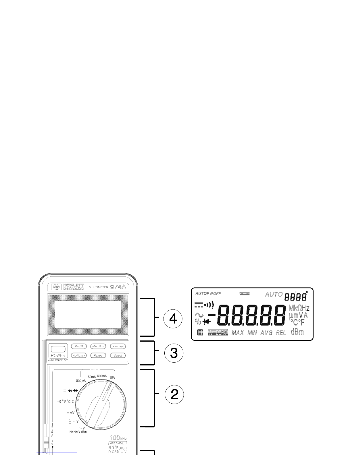
Operation . . . . . . . . . . . . . . . . . . . 1-7
Terminal s, Shutter, & Test Leads . . . 1-7
Function Switch . . . . . . . . . . . . . . 1-8
Function Keys . . . . . . . . . . . . . . . 1-9
Function Keys/Function Switch Matrix . . 1 -1 2
Display . . . . . . . . . . . . . . . . . . . 1-13
Audio . . . . . . . . . . . . . . . . . . . . 1-13
Calibration and Adjustment . . . . . . . . 1-14
Required Test Equipment . . . . . . . . 1-14
Calibration Procedure . . . . . . . . . . 1-14
Maintenanc e . . . . . . . . . . . . . . . . . 1-15
Battery Replacement . . . . . . . . . . . 1-15
Fuse Replacement . . . . . . . . . . . . 1-15
Troubleshooting . . . . . . . . . . . . . . 1-16
Cleaning . . . . . . . . . . . . . . . . . . 1-16
Specifications . . . . . . . . . . . . . . . . 1-17
General . . . . . . . . . . . . . . . . . . . 1-17
DC Voltage . . . . . . . . . . . . . . . . . 1-17
AC Voltage . . . . . . . . . . . . . . . . 1-17
AC + DC Voltage . . . . . . . . . . . . . 1-18
DC Current, AC Current . . . . . . . . . 1-18
Resistance . . . . . . . . . . . . . . . . . 1-19
Continuity . . . . . . . . . . . . . . . . . . 1-19
Diode . . . . . . . . . . . . . . . . . . . . 1-19
Frequency (AC Coupled) . . . . . . . . . 1-19
Temperature . . . . . . . . . . . . . . . . 1-20
dBm . . . . . . . . . . . . . . . . . . . . . 1-20
Adjustments . . . . . . . . . . . . . . . . . 6-1
Calibration Table . . . . . . . . . . . . . . . 6-2
Replaceable Parts/Accessories . . . . . . 6-4
Disassembly . . . . . . . . . . . . . . . . 6-5
Declaration of Conformity
Page 4

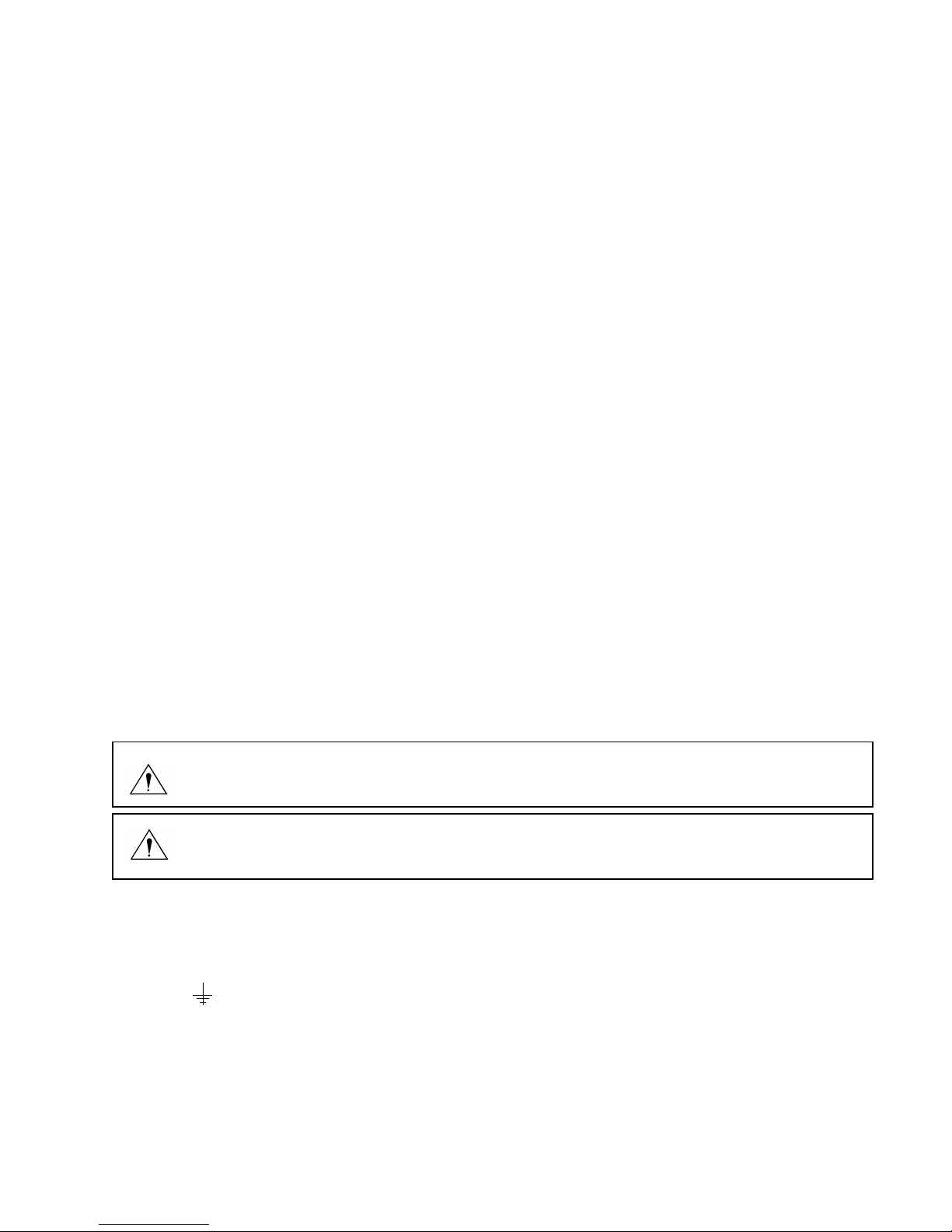
Safety Summary
The CAUTIONS and WARNINGS w hich appe ar on the followi ng p ages mu st b e foll owed t o
ensure operator safety and to retain the operating condition of the Multimeter.
1. Do not use this product beyond its specifications or for uses not intended for this product
as identified by th e prod uct fu nctions , rang es, an d ha zard s as i ndicte d be low.
2. To minimize po ssible el ectric shoc k hazard condition , connect on ly two leads at any one
time to any of the multimeter terminals.
3. To prevent po ssible el ectric shoc k hazard condition when using the curre nt function , do not
leave one probe connected to the circuit under test and the other probe disconnected,
exposed, and rea dily acces sible (tou chab le).
Safety Symbols
Indicates the operator must refer to an explanation in this manual.
Indicates term inals at whic h danger ous volta ges may exis t.
WARNING
TO AVOID ELECTRICAL SHOCK or damage to the multi meter, do n ot app ly mor e th an
±100 0 Vdc or 100 0 Vrms betwee n any termi nal and ea rth ground . Use cauti on when wo rking with
voltages a bove 6 0 Vd c or 4 2 Vp eak. E nsure test lead s ar e in good condi tion .
WARNING
POSSIBLE EL ECTR ICAL SH OCK. Do not make meas ureme nts if the case is d amage d or the
rear cover is removed. Remove all electrical inputs before removing the rear cover.
Page 5
WARNING
POSSIBLE EL ECTR ICAL SH OCK. Ca libr ation and per forma nce te sts ar e to be pe rfor med b y
qualified personnel only. Do not attempt calibration or test procedures unless qualified to do so.
CAUTION
To avoid damage to the multimete r for inputs ab ove 250 Vdc or Vac, disconnec t the test leads
before changing functions. Do not exceed the maximum input limits.
Maximum Overvoltage Limitations (AC and DC Voltage Functions)
1000V
MA X indicates the maxi mu m volt ag e betw ee n inp ut termi na ls an d eart h is ± 1000 V (dc or ac rms).
Do not use the multimeter on any ACV circuit where the maximum impulse overvoltage may
be more tha n 40 00Vpk or a ny D CV circ uit w here t he ma ximu m imp uls e over volta ge ma y be
more than 2500Vpk between the COM and VOLT terminals. Excessive impulse overvoltage
can damage the multimeter voltage functions. Do not measure branch circuits (CAT II) over
600V to earth or servic e panel circ uits (CAT III) over 30 0V to earth.
Safety Summary
Page 6

Function Maximum Operating Input
10 A
± 10 A (dc or ac rms) / 600 V
mA or µA ± 500 mA (dc or ac rms) / 250 V
Resistan ce, Diod e Te st,
Temperature, Continuity
500 V (dc or ac rms)
Frequency
(10 Hz to 9.999 kHz)
(9 kHz to 2 00 k Hz)
500 Vrms
100 Vrms
V
± 1000 Vdc or 750 Vrms
Probes and Test Leads
1. Always inspect probes before use. Do not use test leads whose insulation has cuts,
cracks, or o ther d ama ge tha t may res ult in red uced elec tric sh ock protec tion.
2. Keep insulation surface clean between the probe tip connector and the finger guards.
3. If probes other than th e ones specif ied are to be use d with the mult imeter, be sure the
probes and their leads are rated for the voltage and current to which they will be subjected.
Do not exceed the voltage ratings for the multimeter.
4. Probes supplied with this multimeter are rated for use up to 1000Vrms or Vdc.
Safety Summary
Page 7
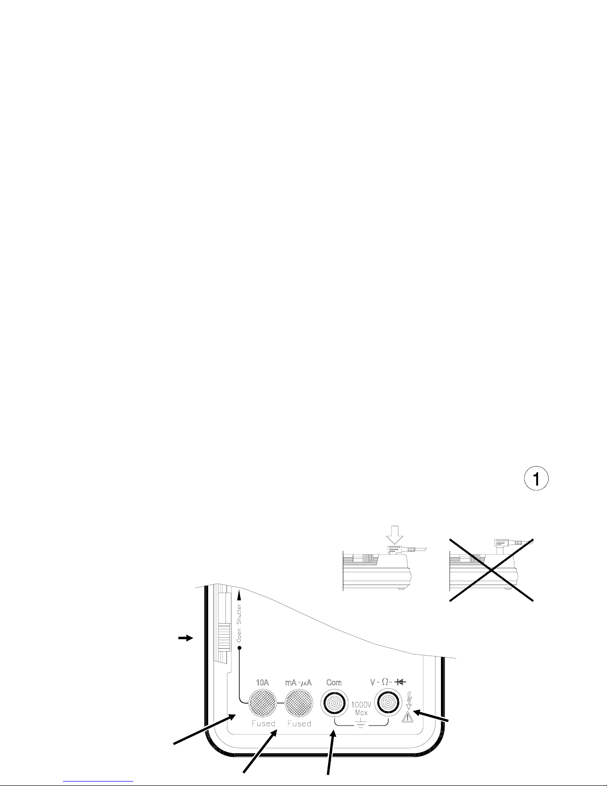
Operation
Terminals, Shutter, & Test Leads
RED LEAD
Current Measurements
(0 A to 10 A)
RED LEAD
RED LEAD
DC & AC Voltage,
Diode, Resistance,
Frequency, Temperature, dBm
and Continuity Measurements
SAFETY SHUT TER
Slide up to open shutters
for current measurement
inputs. Must have the
function switch in one of
the Current Measurement
positions to open shutter.
Close shutter to change
function switch to any
other measurement
function.
Page 8
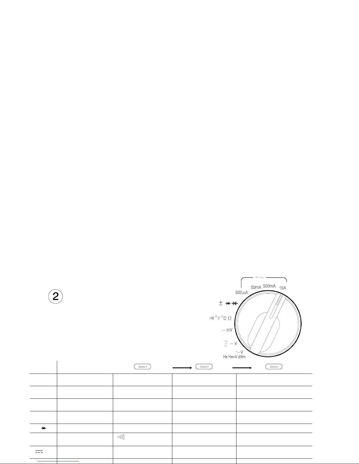
Function Swi tch
Switch
Position
Display
10A
DC Curren t
(1 mA to 10 A)
AC Curr ent
(1 mA to 10 A)
500 mA
DC Curren t
(10 µA to 0.5 A)
AC Curr ent
(10 µA to 0.5 A)
50 mA
DC Curren t
(1 µA to 0.05 A)
AC Curr ent
(1 µA to 0.05 A)
500 µA
DC Curren t
(0.01 µA to 0.5 mA)
AC Curr ent
(0.01 µA to 0.5 mA)
Diode Test Auto Diode Test
Ω
Resistance
( 0.01 Ω to 5 0 M Ω)
Continuity
(alarm at < 100 Ω)
Temperature in °F
(-112° F to 302° F)
Temperature in °C
(-80° C to 150° C)
mV
DC Millivolts
(10 µV to 500 mV)
Operation
Page 9
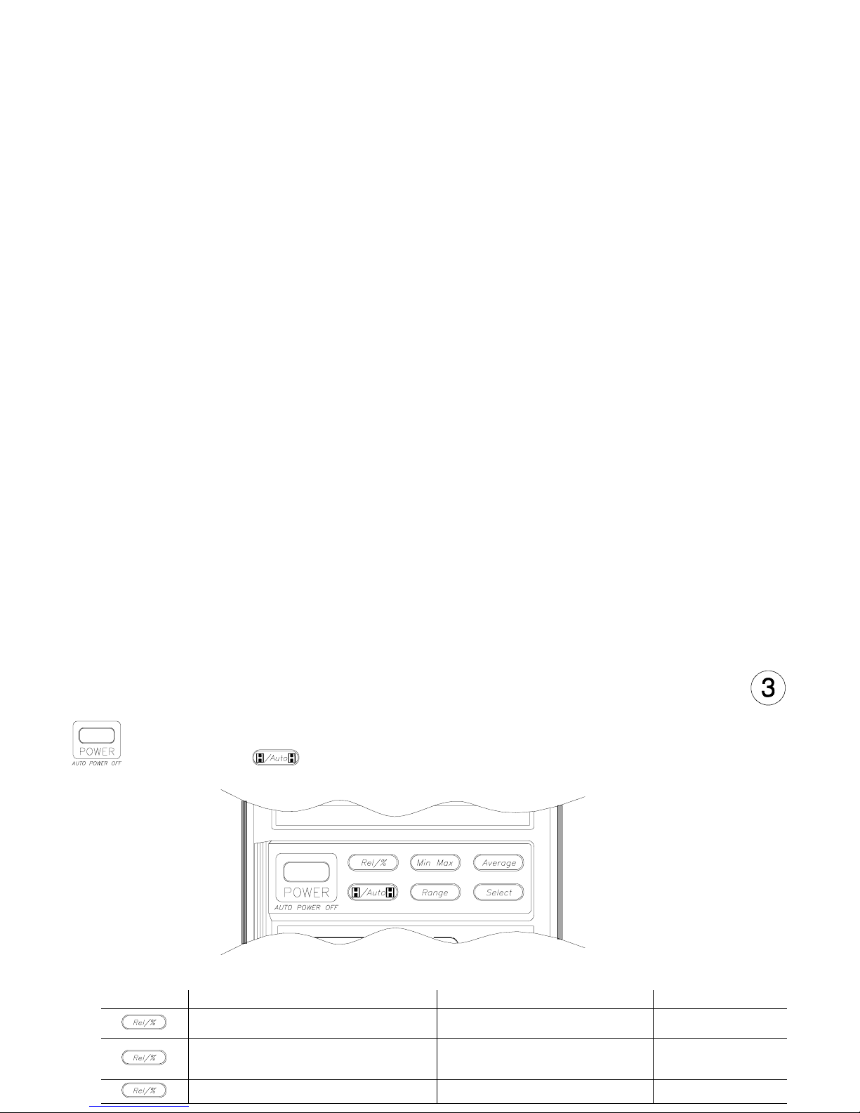
Function K eys
Power
Automatic powe r off after 30 min utes. Ala rm sounds 30 second s before aut omatic pow er off.
Press any key or change any function to cancel automatic power off. Defeat automatic power
off by holding key for 2 second s while ap plying power.
Relative/Percent
Press Action Main Display Secondary Display
Makes the dis played m easure ment
the reference
Each measured value relative to
the reference value (difference)
Range
Calculates the percentage change
from the reference
Each measur ed val ue as a
percent chan ge o f the refe rence
value
Range
Cancels the Relative/% function Measurement value Range
Operation
Page 10

Minimum/Maximum 1
Press Action Main Display Secondary Display 2
Begin recordin g of min, max, and av g
3
values
Each measur ed val ue Elapsed time
Display recorded maximum Maximum measurement Time of Maximum
Display recorded minimum Minimum measurement Time of Minimum
Display recorded average Calculated average Elapsed time
Display las t reco rded meas ureme nt Latest mea surem ent Elapsed time
Pause recordi ng of minimu m and
maximum values
Last measured valu e Total elapsed time
Resume recording of minimum and
maximum values
Each measur ed val ue Elapsed time
Press and hold 1 second to cancel - -
1
Automatic power off is disabled when Min/Max is sel ected.
2
Time is recorded and displayed in minutes and seconds up to 99’ 59". After 99’ 59" time is recorded and
displayed in minutes up to the maximum recording time of 1999 minutes. Recording will stop at the
maximum time.
3
Average is computed from all readings during elapsed time.
Average
Press Action Main Display Secondary D isplay
Makes the dis played m easure ment the
average of t he la st eigh t mea surem ents
Average value of last eight
measurement s
Range
Disables the averaging of measurements Each measurement Range
Operation
Page 11

Hold/Auto-Hold
Press Action Main Display Secondar y Display
Holds the measur ement value i n the
display
Measurement value when
hold pressed
Range
Enters Au to- Hol d fu ncti on
1
Input value Range
Cancels Hold functi on Measurement valu e Range
1
Auto-Hold Operation. When measurement becomes stable, multimeter will beep and save the
stable reading. Removing probe from measurement circuit will display and hold the last stable reading.
Range
Press Action Main Display Secondary Display
Changes fr om au to-ran ging to ma nual
ranging
Measurement value Range
Change manu al range UP on ce with
each keypress
1
Measurement valu e Range
Returns to auto-ranging when key is held
for 1 second
Measurement valu e Range
1
When upper range is reached, the sequence begins again at the lowest range.
Select
Press this key to use the functi ons ind ica ted in ye llow on the m ulti meter . See tabl e on pa ge 1- 8.
Hold this key to test display when turning meter on.
Operation
Page 12

Function Keys and Function Switch Matrix
Function Relative
%
(Percent)
Min/Max 3 Average Data Hold Auto-Hold Range
µA, mA, 10A
••••••
µA, mA, 10A
••••••
•• • • •
•
Ω
•
1
••••••
•
°F, °C
•• •
mV
•• • • •
V
•••••••
••
V
•••••••
Hz Hz+V
••
2
dBm
••
1
Invokes zero adjust when display is less than 99.
2
Changes input attenuator, frequency is always auto range.
3
Secondary display shows elapsed time (in seconds and minutes).
Operation
Page 13

Display
Audio
Power on
First beep at powe r on.
Second beep when beginning to make measurements.
Single beep
Indicates any valid function key press.
Indicates a new High or Low value recorded when in Min/Max function.
Steady repeatin g be ep
Indicates when measurement is steady when using Auto-Hold function.
Rapid repea ting beeps
Indicate s w rong in pu t te rmin als use d fo r fu nc tio n se lec ted.
Indicates an over load co ndition at the measur ement term inals.
Continuous tone
Indicates a resistance of < 100 Ω when using the Continuity fun ction.
Low Battery indicator
Replace batteries when on.
Secondary Display
Shows:
Range (most functions)
except for
Elapsed time (Min/Max)
Main Display
(Not all annunciators shown)
Number of digits is set by range and function
Displays O.L to indicate an overload condition
Entire display flashes if input overvoltage
Operation
Page 14

Calibration and A djustment
Required Test Equipment
The source used for the calibration should have an output accuracy as good or better than
that listed in the specifications.
Calibration Procedure
Environmental range for calibration: 23° C ± 5 ° C, < 80% RH
Calibration i nterv al: 6 M onths
1 Disconnect all inputs from the multimeter and open the case as described on page 6-5.
2 Install new batteries (described below) and close the cover. Turn the multimeter on and allow a
30 minute warm-up. Open the case.
3 Set the multimeter function and range and the source output to the values specified at each step
in the calibrat ion table on page 6-2.
4 When approp riate, mak e the adjus tments ind icated in th e calibr ation tab le to bring th e multimet er
display within the limits.
CAUTION
Dangerous voltages are present during the calibration procedure. Calibration should only be
performed by qualified service technicians Use a non-conductive adjustment tool.
Page 15

Maintenance
Operator protection from electric shock hazard is provided by a double insulated enclosure.
Refer to pages 1-4 and 1-5 for maximum voltage specifications. When servicing, use only
specified repl acemen t parts.
Battery Replacement
Replace the battery when the symbol appears in the display or before calibration. Replace
both batteries at the same time. Use high-quality type AA alkaline (IEC LR6) batteries.
Remove the batteries if the multimeter is to be stored for extended periods of time. Refer to
the disassembl y dra wing on p age 6- 5.
Fuse Replacement
Fuse locations are sh own in the dia gram on pag e 6-5. Fuse s are listed in the replacea ble part
list on page 6-4.
CAUTION
For continued protection use only the specified manufacturers part number or HP part number
fuse for replace ment purpos es.
Page 16

Troublesh ooting
Problem Possible Cause Suggeste d Action
Unit won’t turn on Dead Batteries
Replace batteries
Unit won’t turn off Input limit exceeded
Remove test le ads and pr ess any ke y to reset.
Display flashes and Rapid
beeps
Input limit exce eded
Remove test le ads and pr ess any ke y to reset.
Battery Annun ciato r on Low battery volta ge
Replace batteries
Unable to measure current
10 A or mA - µA
Blown input protec tion fuse
Replace fuse(s)
Cleaning
Wipe instrum ent wi th a soft r ag d amp ened w ith s oap and water. Do no t im merse in w ater .
Do not use chemical cleansers or solvents.
Replaceable Parts/Accessories
Refer to the disassembly diagram on page 6-5.
Maintenance
Page 17

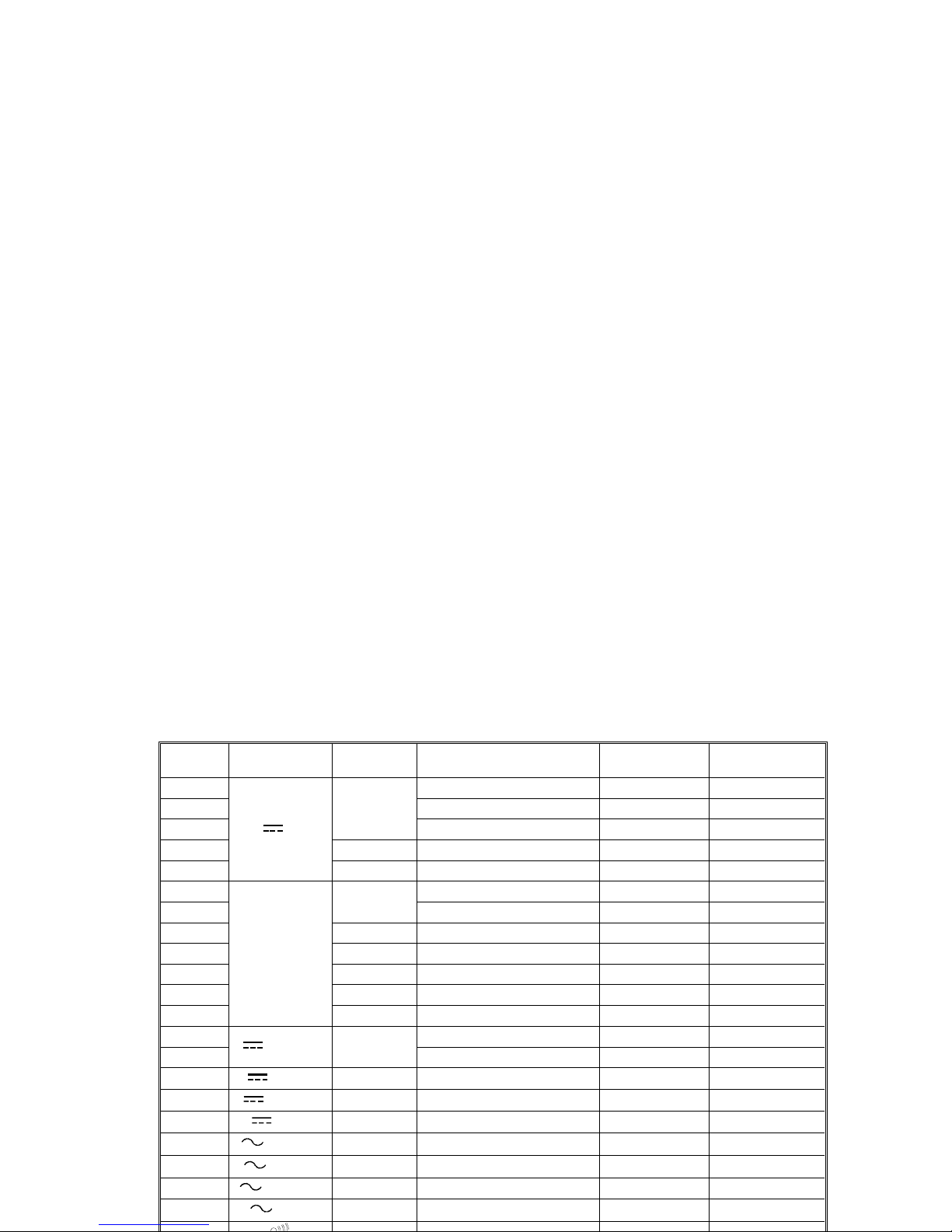
Specifications
Calibration period: six months minimum. Specifications apply at 23°C ± 5°C, < 80% RH
Accuracy = ± (% of reading + number of digits)
Temperature Coefficient = Accuracy 0.1/° C (0° C to 18° C; 28° C to 55° C)
General
Do not expose product to moisture or rain. Do not use product in flammable atmosphere.
Operating Temperature: 0° to 40°C / 80% RH max (no condensati on).
Storage Temperature: -25°C to 60°C / 20% to 70°C RH (no condensation).
Display reading rate: Approximately 2 — 4 times/second
Display rate for frequency measurements: Approximately 1 times/second
Battery life: Approximately 120 hours on DCV
DC Voltage
Range Resolution Accuracy Input Resistance
500 mV
10 µV
± (0 .05% + 2)
> 1000 MΩ
5 V
100 µV
11 MΩ (nominal)
50 V 1 mV
10 MΩ (nominal)
500 V 10 mV
1000 V 100 mV
Normal Mode Rejection Ratio: (NMR) > 60 dB @ 50 or 60 Hz
Effective Common Mode Rejection Ratio (CMR) 1 k Ω imbalance: > 120 dB @ 50 or 60 Hz
AC Voltage (RMS responding, calibrated to display rms)
Range Resolution
Accuracy
Input
Impedance
(nominal)
20 Hz to
50 Hz
50 Hz to
10 kHz
10 kHz to
30 kHz
30 kHz to
50 kHZ
50 kHz to
100 kHz
500 mV
10 µV
± (0.7% +30) ± (2% + 50)
Not Specified
Page 18

AC + DC Voltage (rms responding, computed from acV, dcV)
Range Resolution
Accuracy
DC, 20 Hz to
10 kHz
DC, 10 kHz to
30 kHz
DC, 30 kHz to
50 kHZ
DC, 50 kHz to
100 kHz
5 V 1 mV
± (1% + 30) ± (1.2% + 40) ± (2.5% + 70) ± (3.5% + 300)
50 V 10 mV
500 V 100 mV
750 V 1 V
± (1% + 30)
DC, 20 Hz to 1 kHz
Not Specified
Measurement range:
500 mV to 500 V ranges 20 Hz to 30 kHz 5% to 100% of range
30 kHz to 100 kHz 10% to 100% of range
750 V range 75 V to 750 V
Response time: < 2 seconds for AC, 5 seconds for AC+DC on fixed range
Crest factor: <3
Common Mode Rejection Ratio (CMR) 1 k Ω imbalance: > 60 dB @ DC to 60 Hz
DC Current, AC Current (40 Hz to 1 kHz), 5% to 100% of ran ge
Range Resolution
DC Current
Accuracy
AC Current
Accuracy
Input
Resistance
Maximum
Input
500 µA
10 nA
± (0.3% + 2)
± (1% + 20)
< 1050 Ω
0.5 A (fused)50 mA
1 µA< 12 Ω
500 mA
10 µA < 2.5 Ω
10 A 1 mA
± (0.7% + 2) < 0.05 Ω
15 A (fused)
Specifications
Page 19

Resistance
Range Resolution Accuracy Test Current
Max
Open Circuit
Voltage
500 Ω 10 mΩ± (0.06% + 2)
1
< 800 µA
< 5.5 V
5.0 kΩ 100 mΩ
± (0.06% + 2) 50 kΩ 1Ω < 80 µA
< 2.2 V
500 kΩ 10 Ω < 15 µA
5.0 MΩ 100 Ω ± (0.5% + 1) < 1.5 µA
50 MΩ 1 kΩ ± (1.0% + 2)
< 150 nA
1
After zero adjust of input leads. Zero adjust range up to 0.99 Ω.
Response time: 500 Ω to 500 kΩ — < 2 seconds, 5 MΩ to 50 MΩ — < 10 seconds.
Continuity
Measurement Current: 0.8 mA maximum Open circuit voltage: < 5.5 Vpeak
Displayed resistance: 0 Ω to 499.99 Ω Input protection: 500 Vrms (sinewave)
Alarm: Tone when input < 100 Ω ± 50 Ω Resolution: 10 mΩ (<100 m Sec response time)
Diode
Measurement current: +1.0 mA nominal @ 0.6 V Open circuit voltage: < 5.5 Vpeak
Displayed Voltage: 0 V to 4.999 V Input protection: 500 Vrms (sinewave)
Accuracy: ± (1% + 2) Resolution: 100 µV
Frequency (AC Coupled)
Frequency Range Resolution Accuracy Input Voltage (rms)
10 Hz to 99.99 Hz 0.01 Hz
Specificat ions
Page 20

Temperature (5 kΩ @ 25°C Thermi stor pr obe)
°C °F
Measurement Range
-80° to 150° -112° to 302°
Resolution
0.1° 0.1°
Accuracy
1
± 0.2°± 0.4°
1
Accuracy does not include 5 k Ω Thermistor error
dBm 600 Ω 1 mW reference (rms responding, computed from AC Voltage)
Input dBm Input Voltage
Accuracy
20 Hz to
10 kHz
10 kHz to
30 kHz
30 kHz to
50 kHz
50 kHz to
100 kHz
-29.82 dBm to
-23.80 dBm
25 mV to 50 m V
± 0.2 dBm ± 0. 50 dBm
Not specified
-23.80 dBm to
-3.80 dBm
50 mV to 499.99 mV
± 0.15 dBm ± 0.30 dBm
-3.80 dBm to
55.28 dBm
0.5 V to 450.00 V
± 0.10 dBm ± 0.20 dBm
± 0.5 dBm ± 1.00 dBm
55.28 dBm to
59.72 dBm
450 V to 750 V
± 0.15 dBm
to 1kHz
Not specified
Dynamic range: -59.94 dBm to 59.72 dBm (0.8 mV to 750 V),
Accuracy not specified below -29.82 dBm (25 mV)
Display reads OL (overload) outside dynamic range
Specifications
Page 21

Adjustments
Page 22

Calibration Table
CAUTION
Dangerous voltages are present during the calibration procedure. Calibration should only be
performed by q ualifi ed se rvice techn icia ns u sing a non- cond uctiv e tool .
Step Function Range Input Signal
Adjustment
(limit)
Tolerance
(counts)
1
500 mV
500 mV
Short —
±2
2 480.0 m V
1 (±2) ±26
3 -480.0 mV —
±26
4
V
50 V
48.000 V
2 (±2) ±26
5 -48.000 V —
±26
6 5 V 4.800 V
3 (±2) ±26
7 500 V 480.00 V
RV4 (±2) ±26
8 1000 V 1000 V
RV5 (±1) ±7
9
*
V
5 V
4.8000 V @ 200 Hz
6 (±10) ±270
10
*
0.2500 V @ 200 Hz
7 (±5) ±42
11 500 mV 480.0 mV @ 200 Hz
8 (±10) ±366
12
500 V
480.00 V @ 10 kHz
C1 (±20) ±270
13 480.00 V @ 10 0 kHz —
±1740
14 480.00 V @ 200 Hz —
±270
15
5 V
4 .8000 V @ 10 kHz
C2 (±20) ±270
16 4 .8000 V @ 100 kHz —
±1740
Page 23
Step Function Range Input Signal
Adjustment
(limit)
Tolerance
(counts)
17
V
50 V
48.000 V @ 10 kHz
C3 (±20) ±270
18 48.000 V @ 10 0 kHz —
±1740
19 48.000 V @ 200 Hz —
±270
20 500 mV 480.00 mV @ 10 kHz —
±366
21 750 V 750.0 V @ 200 Hz —
±105
22
Ω
500 Ω
Short zero adjust
1
±1
23
480.00 Ω 9 (±5) ±30
24
5 kΩ 4.8000 kΩ
—
±30
25
50 kΩ 48.000 kΩ
—
±30
26
500 kΩ 480.00 k Ω
—
±30
27
5 MΩ 4. 8000 M Ω
—
±242
28
50 MΩ 48.000 MΩ
—
±482
29
500 µA500 µA
Short —
±2
30
480.00 µA
—
±146
31
50 mA
50 mA 48.000 mA —
±146
32
500 mA
40 mA 480.00 mA —
±146
33
10 A
10 A 10.000 A
10 (±10) ±72
34
500 µA500 µA 480.00 µA @ 200 Hz
—
±500
35
50 mA
50 mA 48.000 mA @ 200 Hz —
±500
36
500 mA
500 mA 480.00 mA @ 20 0 Hz —
±500
37
10 A
10 A 10.00 A @ 200 Hz —
±120
Calibration Table
Page 24

Replaceable Pa rts/Accessorie s
Refer to the disassembly diagram on page 6-5.
Call out Description HP Part Number
F1
Fuse, 500 mA, 250 V fast blow Littlefuse 216-500
DO NOT SUBSTITUTE
2110-0940
F2
Fuse, 1 5 A , 60 0 V fast bl ow L itt lef use KL K15
DO NOT SUBSTITUTE
2110-0941
MP1 Top case assem bly 0097 4-6440 1
MP2 Dust/moisture se al 00 971-6440 3
MP3 Botto m cas e asse mbly ( incl udes s tand) 00974-64402
Rubber Boot 00971-8600 1
Replacement Test Leads, 2 pair E2305A
Temperature probe, 5 KΩ Therm istor
E2308A
Surface temperature sensor,
Thermistor ±0.1°C
12" lead, requi res dual bana na plug
40653B
Soft Case
(fits meter wit h rubber boot)
E2304A
Operator protection from electric shock hazard is provided by a double insulated enclosure. Refer to the Safety
Summary for maximum voltage specifications. When servicing, use only specified replacement parts.
Page 25

Disassembly
WARNING
Always disconnect the test leads before opening the case.
Replaceable Parts/Accessories
Page 26

DECLARATION OF CONFORMITY
according to ISO / IEC Guide 22 and EN 45014
Manufacture r’s Nam e: Hewlett-Packard Company, Personal Measurements Operation
Manufactur er’s A ddress: 815 14th Street S.W., Loveland, Colorado 80537 U.S.A.
declares, that the products
Product Name:
Handheld Multimeter
Model Number: HP 971A, HP 972A, HP 973A, HP 974A
Product Options: None
conforms to the following Product Specifications:
Safety:
IEC 1010-01 (1990) Incl. Amend 1 (1992) / EN61010 (1993)
CSA C22.2 #1010.1 (1992)
UL 1244
EMC: CISPR 11:1990 / EN55011 (1991): Group 1, C lass A
IEC801-2:1991 / EN50082-1 (1992): 4 kV CD, 8 kV AD
IEC 801-3:1984 / EN50082-1 (1992): 3 V/m
IEC 801-4:1988 / EN50082-1 (1992): 0.5 kV Signal Lines
Supplemental Information: The product her ewith complies with the requirements of the
Low Voltage Directive 73 / 23 / EEC and the EMC Directive 89 / 336 / EEC amended
by 93 / 68 / EEC (inclusive 93 / 68 / EEC) and carries the CE mark accordingly.
Loveland, Colorado April 1, 1994
Jim White, QA Manager
Page 27

Warranty/Service
Limited 3 Year Warranty
What is Covered
The HP 974A Multimeter is warranted by Hewlet t-Packard against defects i n material s and
workmanship for three years from the date of original purchase. If you sell your unit or give i t as
a gift, the warranty is automatically transferred to the new owner and remains in effect for the
original three year period. During the warranty period, we will repair, or at our option, replace at
no charge, a product that proves to be defective, provided you return the product, shipping
prepaid, to a Hewlett-Packard service center.
What is Not Covered
This warranty does not apply if the product has been dam aged by accident of misuse or as the
result of service or modification by other than an aut horized Hewlett-Packard service center.
No other express warranty is given. The repair or replacement of a product is your exclusive
remedy. ANY OTHER IMPLIED WARRANTY OF MERCHANTABILITY OR FITNESS IS LIMITED
TO THE THREE YEAR DURATION OF THIS WRITTEN WARRANTY. Some states, provinces, or
countries do not allow the exclusion or l imit ation or i ncidental or consequential damages, so the
above limitation or exclusion m ay not apply to you.
The warranty gives you specific legal rights, and you may also have other rights which vary
from state to state, province to province, or count ry to country.
Service
Hewlett-Packard maintains service centers in many countries throughout the world. You may
have your unit repaired at a Hewlett-Packard service center any time it needs service, whether
the unit is under warranty or not. There is a charge for repairs after the warranty peri od. Repair
or replacement during the first 30 days after purchase will be provided by the sales channel.
After 30 days, contact the nearest service office.
Hewlett-Packard products normally are repaired and reshipped within five (5) working days of
receipt at any service center. This is an average time and could possibly vary depending upon
the time of year and work load at the service center. The total time you are without your unit will
depend largely on the shipping t ime.
 Loading...