


HP 972A and 973A Multimeter
User’s Guide
Part Number 00972-90002
March 1995
© Copyright Hewlett-Packard Company 1994, 1995
All Rights Reserved
972A
973A

HP 972A and 973A Multimeters
Table of Contents
Safety Summary . . . . . . . . . . . . . . . 1-4
Safety Symbols . . . . . . . . . . . . . . 1-4
Maximum Overvoltage Limitations . . . 1-5
Probes and Test Leads . . . . . . . . . 1-6
Operation . . . . . . . . . . . . . . . . . . . 1-7
Terminals, Shutter, & Test Leads . . . 1-7
Function Switch . . . . . . . . . . . . . . 1-8
Function Keys . . . . . . . . . . . . . . . 1-9
Function Keys/Function Switch Matrix . . 1-12
Display . . . . . . . . . . . . . . . . . . . 1-13
Audio . . . . . . . . . . . . . . . . . . . . 1-13
Calibration and Adjustment . . . . . . . . 1-14
Required Test Equipment . . . . . . . . 1-14
Calibration Procedure . . . . . . . . . . 1-14
Maintenance . . . . . . . . . . . . . . . . . 1-15
Battery Replacement . . . . . . . . . . . 1-15
Fuse Replacement . . . . . . . . . . . . 1-15
Troubleshooting . . . . . . . . . . . . . . 1-16
Cleaning . . . . . . . . . . . . . . . . . . 1-16
Replaceable Parts/Accessories . . . . . 1-16
Specifications . . . . . . . . . . . . . . . . 1-17
General . . . . . . . . . . . . . . . . . . . 1-17
DC Voltage . . . . . . . . . . . . . . . . . 1-17
AC Voltage HP 972A . . . . . . . . . . . 1-18
AC Voltage HP 973A . . . . . . . . . . . 1-18
AC + DC Voltage HP 973A . . . . . . . 1-19
DC Current . . . . . . . . . . . . . . . . . 1-19
AC Current . . . . . . . . . . . . . . . . . 1-20
Resistance . . . . . . . . . . . . . . . . . 1-20
Continuity . . . . . . . . . . . . . . . . . . 1-20
Diode . . . . . . . . . . . . . . . . . . . . 1-20
Capacitance . . . . . . . . . . . . . . . . 1-20
Frequency (Volts) . . . . . . . . . . . . . 1-21
Frequency (Amps) . . . . . . . . . . . . . 1-21
Temperature . . . . . . . . . . . . . . . . 1-22
Temperature HP 973A . . . . . . . . . . 1-22
dBm HP 973A . . . . . . . . . . . . . . . 1-22
Adjustments . . . . . . . . . . . . . . . . . 6-1
Calibration Table . . . . . . . . . . . . . . . 6-1
Replaceable Parts/Accessories . . . . . . 6-4
Disassembly . . . . . . . . . . . . . . . . 6-5
Declaration of Conformity
1 - 3
Safety Summary
The CAUTIONS and WARNINGS which appear on the following pages must be followed to
ensure operator safety and to retain the operating condition of the Multimeter.
1. Do not use t his prod uct beyo nd its spe cificati ons or f or uses no t intend ed for t his produc t
as identified by the product functions, ranges, and hazards as indicted below.
2. To minimize possible electric shock hazard condition, connect only two leads at any one
time to any of the multimeter terminals.
3. To prevent possible electr ic shock ha zard co ndition when us ing the curren t functi on, do
not leave one probe connected to the circuit under test and the other probe disconnected,
exposed, and readil y accessib le (tou chable) .
Safety Symbols
Indicates the operator must refer to an explanation in this manual.
Indicates terminals at which dangerous voltages may exist.
WARNING
TO AVOID ELECTRICAL SHOCK or damage to the multimeter, do not apply more than
±1000 Vdc or 1000 Vrms between any terminal and earth ground. Use caution when working
with voltages above 60 Vdc or 42 Vpeak. Ensure test leads are in good condition.
WARNING
POSSIBLE ELECTRICAL SHOCK. Do not make measurements if the case is damaged or the
rear cover is removed. Remove all electrical inputs before removing the rear cover.
WARNING
POSSIBLE ELECTRICAL SHOCK or FIRE HAZARD. Do not expose this multimeter to rain or
moisture. Do not operate the multimeter in the presence of flammable gases or fumes.
1 - 4
Safety Summary
WARNING
POSSIBLE ELECTRICAL SHOCK. Calibratio n and pe rforma nce test s are to be perf ormed b y
qualified personnel only. Do not attempt calibration or test procedures unless qualified to do so.
CAUTION
To avoid damage to the multimeter for inputs above 250 Vdc or Vac, disconnect the test leads
before changing functions. Do not exceed the maximum input limits shown in the following table.
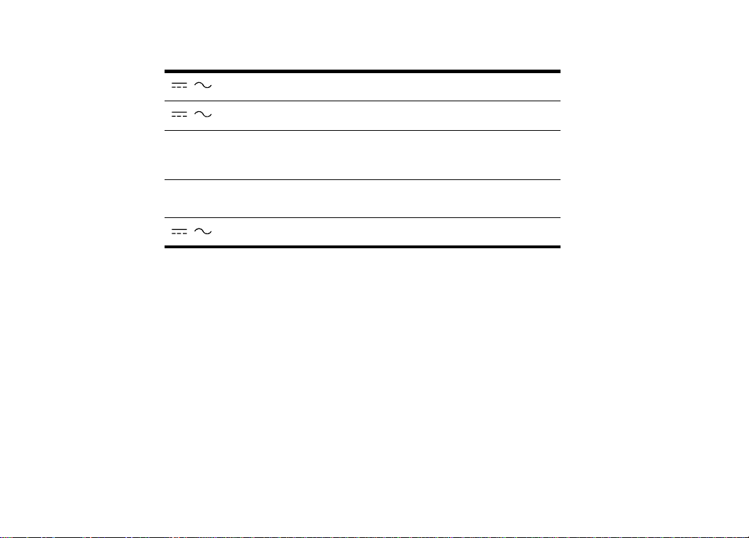
Maximum Overvoltage Limitations (AC and DC Voltage Functions)
1000V
MA X indicates th e ma xi mu m vo lt age b et wee n i npu t ter mi nal s an d ea rt h i s ± 1000 V (dc or ac rms).
Do not use the multimeter on any ACV circuit where the maximum impulse overvoltage may
be more than 4000Vpk or any DCV circuit where the maximum impulse overvoltage may be
more than 25 00Vpk bet ween th e COM an d VOLT termi nals. Ex cessive impulse overvol tage
can damage t he multi meter vo ltage f uncti ons. Do n ot meas ure bra nch circui ts (CAT I I) over
600V to earth nor service panel circuits (CAT III) over 300V to earth.
1 - 5
Safety Summary
Function Maximum Operating Input
10 A
mA or µA ± 500 mA (d c or ac r ms) / 25 0 V
Capacitance, Diode Test,
Resistance, Continuity,
Temperature
Frequency
V
± 10 A (dc or ac rms) / 600 V
660 Vrms (sinewave)
660 V rms 2 Hz to 10 kHz
100 V rms 10 kHz t o 200 kHz
± 1000 Vdc or Vrms (sinewave)
Probes and Test Leads
1. Always inspect probes before use. Do not use test leads whose insulation has cuts,
cracks, or oth er damag e that may res ult in re duced e lectric shock p rotecti on.
2. Keep insulat ion surf ace clea n betwee n the pro be tip c onnecto r and the finger guards.
3. If probes other than the ones specified are to be used with the multimeter, be sure the
probes and their leads are rated for the voltage and current to which they will be subjected.
Do not exceed the voltage ratings for the multimeter.
4. Probes supplied with this multimeter are rated for use up to 1000Vrms or Vdc.
1 - 6
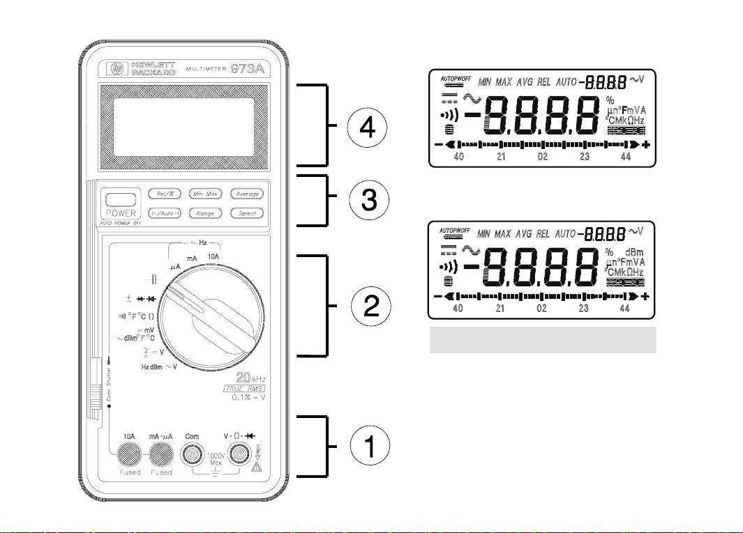
Operation
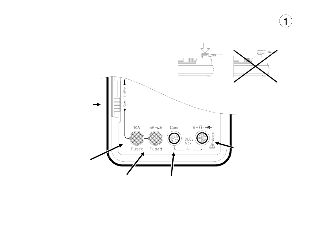
Terminals, Shutter, & Test Leads
SAFETY SHUTTE R
Slide up to open shutters
for current measurement
inputs. Must have the
function switch in one of
the Current Measurement
positions to open shutter.
Close shutter to change
function switch to any
other measurement
function.
RED LEAD
Current Measurements
(0 A to 10 A)
Frequency (Amps) Measurements
RED LEAD
DC & AC Voltage,
Diode, Resistance,
Capacitance, Frequency (Volts),
Temperature, Continuity, and
dBm Measurements
RED LEAD
Current Measurements
(0 to 400 mA)
Frequency (Amps)
Measurements
BLACK LEAD
COMMON
ALL Measurements
1 - 7
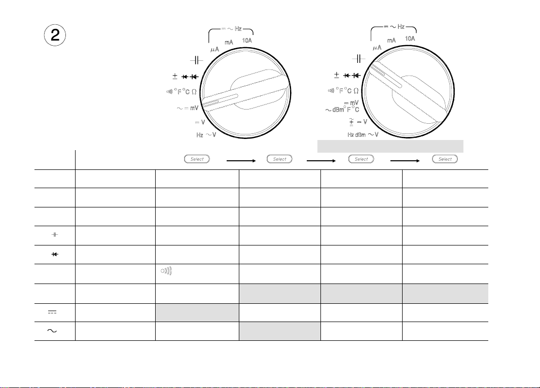
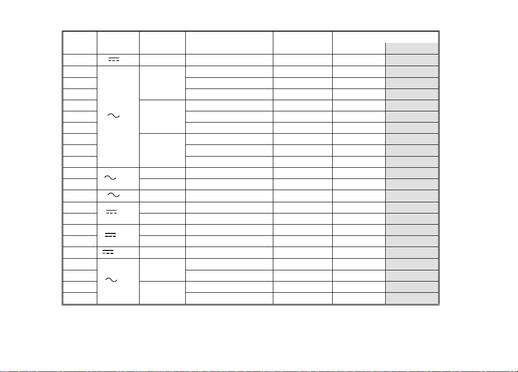
Function Switc h
Switch
Positio n
10A
mA
µA
Ω
mV
V
V
1 - 8
HP 972A HP 973A
Display
DC Current
(10 mA to 10 A)
DC Current
(10 µA to 0.4 A)
DC Current
(0.1 µA to 4 mA)
Capacitance
(10 pF to 1000 µF)
Diode Test
(0 to 2 V)
Resistance
( 0.1 Ω to 40 MΩ)
DC volts
(10 µV to 400 mV)
DC Volts
( 1 mV to 1000 V)
AC volts
( to 1000 V)
1 AC input value is shown in secondary display
AC Current
(10 mA to 10 A)
AC Current
(10 µA t o 0. 4 A)
AC Current
(0.1 µA to 4 mA)
Auto Diode Test
(0 to ±2 V)
Continuity
(alarm at < 20 Ω)
AC volts
(10 µV to 400 mV)
DC + AC Volt s
( to 1000 V)
Frequency
(2 Hz to 200 kHz)
1
Frequency
(2 Hz to 10 kHz)
Frequency
(2 Hz to 10 kHz)
Frequency
(2 Hz to 10 kHz)
Temperature in °F
(-112° F to 302° F)
(-59.9 to -5.7 dBm)
(-19.9 to 62.2 dBm)
dBm
dBm
1
1
1
Temperature in °C
(-80° C to 150° C)
Temperature in °F
(-58° F to 1292° F)
Temperature in °C
(-50° C to 700° C)
Operation
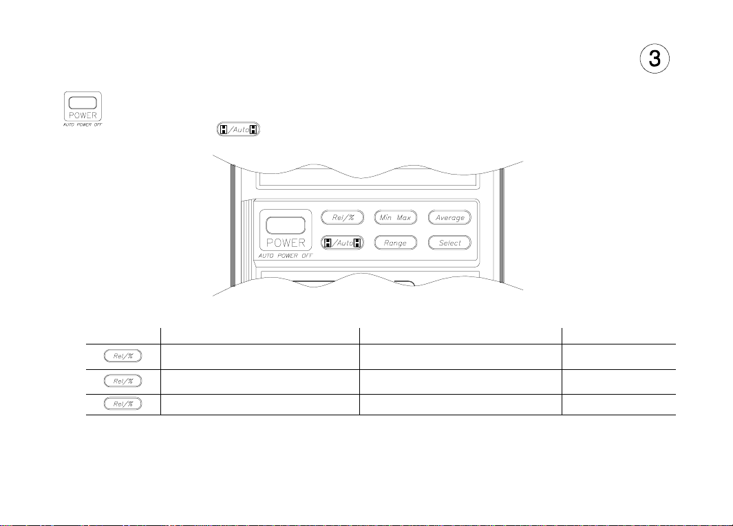
Function Key s
Power
Automatic power off after 30 minutes. Alarm sounds 30 seconds before power off.
Power off if input < 80 V or < 400 mA. Power save if input > 80 V or > 400 mA, last measurement
displayed, power consumption is reduced. Press any key or change any function to cancel. Defeat
by holding the key for 2 seconds while applying power.
Relative/Percent
Press Action Main Display Secondary Display
Makes the last displayed
measurement the reference
Calculates th e perce ntage ch ange
Perform a zero adjust when using the 400 Ω range or 40 mV range and displayed value is less than 99 by
shorting the test leads and pressing this key. Perform a zero adjust on the 10 nF Capacitance range with the
leads open. Cycle power to erase the stored zero adjustment.
from the reference
Cancels the R elative /% func tion Measured Val ue Range
Each measured value relative to
the referenc e value ( differe nce)
Each measured value as a percent
change of the reference value
Reference valu e
Reference valu e
1 - 9

Operation
Minimum/Maximum 1
Press Action Main Display Secondary Display 2
Begin recording of
minimum and maximum values
Each measured value Elapsed time
Display recorded maximum Maximum measurement Time of Maximum
Display recorded minimum Minimum measurement Time of Minimum
Display last recorded measurement Latest measurement Elapsed time
Pause recording of
minimum and maximum values
Resume recording of
minimum and maximum values
3
Holds display Total elapsed time
Each measured value Elapsed time
Press and hold 1 second to canc el ——
1
Automatic power off and auto ranging are disabled when Min/Max is selected. Bargraph will indicate and
hold the maximum values of the bargraph.
2
Time is recorded and displayed in minutes up to the maximum recording time of 1999 minutes.
Recording will stop at the maximum time.
3
H annunciator is displayed when Min/Max recording
Average
Press Action Main Display Secondary Display
Makes the displayed measurement the
average of the last eight measurements
Disables the averaging of measurements Each measurement Range
Average value of last eight
measurements
Range
1 - 10

Operation
Hold/Auto-Hold
Press Action Main Display Secondary Display
Holds the me asureme nt valu e in the display
Enters Auto-Hold function
1
Measurement v alue whe n
hold presse d
Measurement v alue whe n
multimeter be eps
Input value
Range
Cancels Hold function Measurement value Range
1
Auto-Hold Operation. When measurement becomes stable, multimeter will beep and save the stable
reading. Removing probe from measuring circuit will display and hold the last stable reading.
Range
Press Action Main Display Secondary Display
Changes from a uto-r anging t o manua l
Change manual range
UP once with each keypress
Returns to auto-ranging when key is held
1
When upper range is reached, the sequence begins again at the lowest range.
ranging
for 1 second
1
Measurement value Range
Measurement value Range
Measurement value Range
Select
Press this key to use the functions indicated in yellow on the multimeter. See table on page 1-8.
To test display, hold this key when turning meter on.
HP 973A: Not all annunciators turned on during the display test.
1 - 11

Operation
Function Keys and Function Switch Matrix
Function Relative
µA, mA
10A
Hz(Amps) 6
7
Ω
°F, °C Therm
dBm 7
°F, °C Tcp
Hz(Volts) 6
dBm7
7
mV
mV
3
7
V
7
V
3
1
Zero adjust when display shows < 99 on lowest range.5 Secondary display shows elapsed time (in minutes).
2
Secondary display shows reference value.
3
Secondary display shows AC input voltage.
4
Changes input attenuator, frequency is always auto range.
2
•
••••
2
•
••••
1
•
2
••
•
1,2
•
•• •
1,2
•
2
•
••••
2
•
•
•• •
2
•
••••
2
•
••••
2
•
•
%
(Percent)
Min/Max 5 Average Data Hold Auto-Hold Range
••
••••6••
••••
1 - 12
6
6
3
•
6
6
•
••
•
4
•
•
•
6
6
6
••
•
•
••
6
3
•
6
Secondary display and bargraph updates with input value.
7
Bargraph not available.
••
4
•

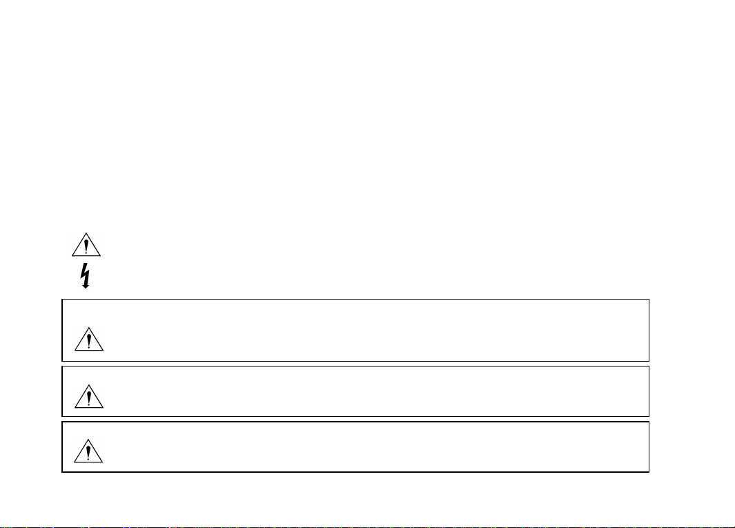
Display
Low Battery indicator
Replace batteries when on.
Main Display
(Annunciators shown inside front cover)
Number of digits is set by range and function
Displays O.L to indicate an overload condition
Entire display flashes if:
Input overvoltage or
During Amps fuse check
Audio
Secondary Display
Shows:
Range (most functions)
AC input value (Frequency)
Reference value (Relative/%)
Elapsed time (Min/Max)
Bargraph
Active for all functions except:
Capacitance, Temperature,
AC +DC, dBm
Power on
First beep at pow er on.
Second beep wh en begin ning to m ake measur ements .
Single beep
Indicates any valid function key press.
Indicates a new High or Low value recorded when in Min/Max function.
Steady repeating beep
Indicates wh en measu remen t is stea dy when us ing Aut o-Hold f unction .
Rapid repeatin g beeps
Indicates wrong input terminals used for function selected.
Indicates an overload condition at the measurement terminals.
Continuous ton e
Indicates a resistance of < 20 Ω when using the Continuity function.
Auto Power Off/Auto Power Save
Pairs of beep s for 30 second s.
Long beep just before power off.
Cancel by changing function switch position or pressing any key.
1 - 13

Calibration and Adjustment
Required Test Equipment
The source used for the calibr ation s hould ha ve an ou tput ac curacy as good or better than
that listed in the specifications.
Calibration Procedure
Environmental range for calibration: 23° C ± 5° C, < 80% RH
Calibration interval: 1 Year
1 Disconnect all input s from th e multi meter a nd open the case as desc ribed on page 6- 5.
2 Install new ba tteries (describe d below) and clos e the cov er. Turn t he mult imeter o n and allo w a
30 minute war m-up. Op en the ca se.
3 Set the multimeter function and range and the source output to the values specified at each step
in the table on page 6- 1.
4 When appropriate, make the adjustments indicated in the table to bring the multimeter display
within the limits.
CAUTION
Dangerous voltages are present during the calibration procedure. Calibration should only be
performed by qualif ied ser vice tech nician s. Use a n on-con ductive a djustm ent to ol.
1 - 14

Maintenanc e
Operator protection from electic shock hazard is provided by a double insulated enclosure.
Refer to pag es 1-4 and 1-5 fo r maximu m volt age speci ficatio ns. Whe n servici ng, use o nly
specified re placemen t parts .
Battery Replacement
Replace the battery when the symbol appears in the display or before calibration. Replace
both batteries at the same time. Use high-quality type AA alkaline (IEC LR6) batteries.
Remove the batteries if the multimeter is to be stored for extended periods of time. Refer to
the disassembly drawing on page 6- 5.
Fuse Replacement
Fuse locations are shown in the diagram on page 6-5. Fuses are listed in the replaceable part
list on page 6-4. See fuse check procedure in the Troubleshooting table below.
CAUTION
For continued protecti on use on ly the spe cified ma nufact urer pa rt number or HP part number
fuse for re placemen t purp oses.
1 - 15

Maintenance
Troubleshooting
Problem Possible Cause Suggested Action
Unit won’t turn on Dead Batteries
Unit won’t tu rn off Input limit exceed ed
Display flashes
and
Rapid beeps
Battery Annunciator on Low battery voltage
Unable to measure
current
10 A or mA - µA
Input limit exceed ed
Test leads i n wron g
terminal for measurement
Open input protection fuse
function
Replace batter ies
Remove test l eads a nd pres s any ke y to re set
Remove test l eads a nd pres s any ke y to re set
Change test leads or function switch position
Replace batter ies
Check fuse. Connect test lead between V input
terminal and 1 0A or mA µA terminal. Unit will
rapidly beep if fuse is OK. Replace fuse if no
beep.
Cleaning
Wipe instrument with a soft rag dampened with soap and water. Do not immerse in water.
Do not use chemical cleanser or solvents.
Replaceable Parts/Accessories
Refer to the d isassem bly di agram on page 6- 5.
1 - 16
Specifications
Calibration period: one year minimum. Specifications apply at 23° C ± 5° C, < 80% RH
Accuracy = ±(% of reading + number of digits)
Temperature Coefficient = Accuracy X 0.1/° C (-10° C to 18° C; 28° C to 55° C)
General
Do not expose product to moisture or rain. Do not use product in flammable atmosphere.
Operating Temperature: -10° to 50°C.
Humidity: 0°C to 40°C / 80% RH max, 40°C to 50°C / 70% RH max (no condensation).
Storage Temperature: -25° to 60°C / 70% RH max (no condensation).
Display reading rate:
ACV, DCV, Diode, Continuity: Approximately 2.3/second
Frequency Approximately 1/second
Capacitance Approximately 0.03 to 2/second
AC + DC Approximately 0.5 to 1/second
Bargraph reading rate: Approximately 23/second
Battery life: Approximately 600 hours
DC Voltage
Range Resolution
40 mV
400 mV
4 V 1 mV
40 V 10 mV
400 V 100 mV
1000 V 1 V
Normal Mode Rejection Ratio: > 60 dB @ 50 or 60 Hz
Effective Common Mode Rejection Ratio ( 1 kΩ imbalance): > 120 dB @ 50 or 60 Hz
972A 973A
Accuracy
10 µV ± (0.3% + 5) ± (0.3% + 5)
100 µV
± (0.2% + 1)
± (0.1% + 1)
± (0.2% + 1)
Input Resistance
10 MΩ (nominal)
11 MΩ (nominal)
10 MΩ (nominal)
1 - 17

Specifications
AC Voltage HP 972A (Average responding, calibrated to display rms)
Range Resolution
40 mV
10 µV ± (1% + 1 0)
400 mV 0.1 m V
4 V 1 mV
40 V 10 mV
400 V 100 mV
1000 V 1 V
Common Mode Rejection Ratio (1 kΩ imbalance): > 60 dB @ DC to 60 Hz
Response time: 2 seconds maximum
40 Hz to
50 Hz
± (1% + 3)
± (1% + 3)
± (1% + 2) ± (0.5% + 2)
± (1% + 2) (40 Hz to 50 0 Hz)
50 Hz to
1 kHz
Accuracy
1 kHz to
5 kHz
Not Specified
Not Specified
± (1.5% + 3) ± (3% + 6)
Not Specified
5 kHz to
20 kHZ
AC Voltage HP 973A (True rms, calibrated for sinewave)
Range Resolution
40 mV
10 µV
400 mV 0.1 mV
4 V 1 mV
40 V 10 mV
400 V 100 mV
1000 V 1 V
Measurement range:
40 Hz to 1 kHz 40 m V to 400 V range 5% to 100% of range
1 kHz to 20 kHz 4 V to 400 V range 10% to 100% of range
Response time: <2 seconds on fixed range
Crest factor: <3
Common Mode Rejection Ratio (1 kΩ imbalance): > 60 dB @ DC to 60 Hz
40 Hz to
50 Hz
± (1% + 3)
± (1% + 3)
± (0.7% + 3) ± (1.2% + 4) ± (2% + 15)
± (1% + 4) (40 Hz to 50 0 Hz)
1000 V range 100 V to 1000 V
50 Hz to
1 kHz
Accuracy
1 kHz to
5 kHz
Not Specified
Not Specified
5 kHz to
20 kHZ
Input Impedance
(nominal)
10 MΩ < 70 pF
11 MΩ < 50 pF
10 MΩ < 50 pF
Input Impedance
(nominal)
10 MΩ < 70 pF
11 MΩ < 50 pF
10 MΩ < 50 pF
1 - 18

AC + DC Voltage HP 973A (True rms, computed from acV, dcV)
Range R esolution
4 V 1 mV
40 V 10 mV
400 V 100 mV
1000 V 1 V
Measurement range:
DC, 40 Hz to 1 kHz 4 V to 400 V range 5% to 100% of range
DC, 1 kHz to 20 kHz 4 V to 400 V range 10% to 100% of range
Response time: < 5 seconds on fixed range
Crest factor: <3
Common Mode Rejection Ratio (1 kΩ imbalance): > 60 dB @ DC to 60 Hz
DC, 40 Hz to
1 kHz
± (1% + 4) ± (1.5% + 6) ± (3% + 18)
± (1% + 6)
DC, to 500 Hz
1000 V range 200 V to 1000 V
Accuracy
DC, 1 kHz to
5 kHz
Not Specified
DC, 5 kHz to
20 kHZ
DC Current
Range Resolution Accuracy Input Resistance Maximum Input
400 µA
4000 µA1 µA
40 mA
400 mA
10 A 10 mA
100 nA
10 µA
100 µA
± (0.5% + 2)
± (0.8% + 2)
± (1.0% + 2)
< 550 Ω
< 8 Ω
< 0.05 Ω ± 15 A (fus ed)
Specifications
Input
Impedance
(nominal)
11 MΩ < 50 pF
10 MΩ < 50 pF
± 0.5 A (fused)
1 - 19

Specifications
1 - 20
AC Current
Range Resolution
400 µA
100 nA
Accuracy
(40 Hz to 2 kHz)
4000 µA1 µA
40 mA
400 mA
10 µA
100 µA
± (1.5% + 4)
10 A 10 mA
HP 972A average responding
HP 973A rms responding, crest factor <3, specified for 5% to 100% of range
Input
Resistance
< 550 Ω
< 8 Ω
< 0.05 Ω
Resistance
Range Resolution Accuracy Test Current
1
400 Ω 100 mΩ± (0.2% + 1)
4.0 kΩ 1 Ω
40 kΩ 10 Ω < 10 µA
± (0.2% + 1)
< 0.8 mA < 3.2 V
< 80 µA
400 kΩ 100 Ω < 1.1 µA
4.0 MΩ 1 kΩ ± (0.5% + 1)
40 MΩ 10 kΩ ± (1.2% + 1)
1
After zero adjust of input leads. Zero adjust range up to 9.9 Ω.
110 nA
Continuity
Measurement Current: 0.8 mA maximum Open circuit voltage: < 3.2 Vpeak
Displayed resistance: 0 Ω to 400 Ω Input protection: 660 Vrms (sinewave)
Alarm: Tone when input < 20 Ω Resolution: 100 mΩ
Diode
Measurement current: +0.5 mA nominal @ 0.6 V Open circuit voltage: < 3.2 Vpeak
Displayed Voltage: 0 V to 2.000 V Input protection: 660 Vrms (sinewave)
Accuracy: ± (1% + 2) Resolution: 1 mV
Maximum Input
0.5 Arms (fused )
15 Arms (fused)
Max Open
Circuit Voltage
< 1.1 V

Capacitance
Range Resolution Accuracy
10 nF 10 pF
100 nF 100 pF
1000 nF 1 nF
10 µF
100 µF
1000 µF1 µF
1
After zero adjust of input leads
Method used: Charge/Discharge of capacitor under test
Maximum display 1199
10 nF
100 nF
1
± (2% + 3)
± (1.2% + 2)
± (3% + 2)
Frequency (Volt s)
Frequency Range Res olution Accuracy Input Voltage (rms)
2 Hz to 99.99 Hz 0.01 Hz
900 Hz to 9999 Hz 1 Hz 0.4 V to 400 V
9.00 kHz to 99.99 kHz 10 Hz 0.8 V to 100 V
90 kHz to 200 k Hz 100 Hz 2 V to 100 V
± (0.02% + 1)
0.2 V to 400 V
Frequency (Amps)
Frequency Range Resolution Accuracy Input Current (rms)
2 Hz to 99.99 Hz 0.01 Hz
± (0.02% + 1) 50 µA to 10 A
900 Hz to 9999 Hz 1 Hz
Response time 3 sec max on fixed range
Specifications
Maximum
Input
660 Vrms90 Hz to 999.0 Hz 0.1 Hz
100 Vrms
Maximum
Input
15 A (fused)90 Hz to 999.0 Hz 0.1 Hz
1 - 21

Specifications
Temperature (5 kΩ @ 25° C Thermistor probe)
° C ° F
Measurement R ange
Resolution
1
Accuracy
1
Accuracy does not include 5 kΩ Thermistor error
-80° to 150° -112° to 302°
0.1° 0.2°
± 0.3° C ± 0.5° F
Temperature HP 973A (K type Thermocouple probe)
° C ° F
Measurement R ange
Resolution
1
Accuracy
1
Accuracy does not include K type Thermocouple error
-50° to 700° -58° to 1292°
1° 1°
± (2% + 2°) ± (2% + 4 °)
dBm HP 973A (600 Ω, 1 mW reference)
Function Input dBm Input Voltage
ACmV -51.8 dBm to -5.7 dBm 2.0 mV to 400 mV
-11.8 dBm to -5.7 dBm 0.2 V to 0.4 V
AC V
-5.7 dBm to 53.3 dBm 0.4 V to 360 V
53.3 dBm to 62.2 dBm 360 V to 1000 V
40 Hz to 1 kHz
± 0.3 dBm
± 0.2 dBm
± 0.2 dBm
40 Hz to 500 Hz
Accuracy
1 kHz to
5 kHz
5 kHz to
20 kHz
Not specified
± 0.2 dBm ± 0.7 dBm
Not specified
1 - 22

Adjustme nts
973A
972A
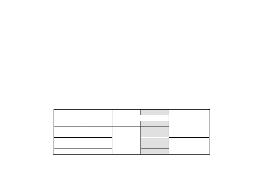
Calibration Ta ble
CAUTION
Dangerous voltages are present during the calibration procedure. Calibration should only be
performed by qualif ied ser vice tech nician s. Use a n on-con ductive t ool.
Step Function Range Input Signal
1
2 380.0 mV
3 40 mV 38.00 mV
4
5 4 V 3.800 V
6 40 V 3 8.00 V
mV
400 mV
400 V 380.0 V
V
Short —
Adjustment
(limits)
1 (±1) ±8 ±4
2 (±1) ±18 ±16
3 (±1) ±8 ±4
4 (±1) ±8 ±4
5 (±1) ±8 ±4
Tolerance (counts)
972A 973A
±1 ±1
6 - 1
Calibration Table
Step Function Range Input Signal
7
8
9 380.0 V @ 5 kHz
10 380.0 V @ 20 kHz —
11
12 3.800 V @ 100 Hz —
13 3.800 V @ 20 kHz —
14
15 38.00 V @ 100 Hz —
16 38.00 V @ 20 kHz —
17
18 400 mV 380.00 mV @ 100 Hz —
19
20
21
22
23 400 mA 380.0 mA —
24
25
26
27
28
mV
µA
mA
10 A
µA
1000 V 1000 V —
V
380.0 V @ 100 Hz
400 V
3.800 V @ 5 kHz
V
V
4 V
38.00 V @ 5 kHz
40 V
40 mV 38.00 mV @ 100 Hz
1000 V 1000 V @ 100 Hz —
400 µA380.0 µA
4000 µA 3800 µA
40 mA 38.00 mA —
10 A 10.00 A
400 µA
4000 µA
380.0 µA @ 100 Hz
380.0 µA @ 2 kHz
3800 µA @ 100 Hz
3800 µA @ 2 kHz
Adjustment
(limits)
6A or 6B (±2) ±21 ±29
C1 (±3) ±60 ±49
C2 (±3) ±60 ±49
C3 (±3) ±60 ±49
Tolerance (counts)
972A 973A
±3 ±3
±120 ±91
±21 ±29
±120 ±91
±21 ±29
±120 ±91
7 (±2) ±48 ±41
±41 ±41
±12 ±14
—
—
8 (±2) ±12 ±12
—
—
—
—
±21 ±21
±32 ±32
±32 ±32
±40 ±40
±61 ±61
±61 ±61
±61 ±61
±61 ±61
6 - 2

Calibration Table
Step Function Range Input Signal
29
30 38.00 mA @ 2 kHz —
31
mA
32 380.0 mA @ 2 kHz —
33
34 10.00 A @ 2 kHz —
10 A
35
36
37
38
Ω
39
40
41
42
40 mA
400 mA
10 A
400 Ω
4 kΩ 3.800 kΩ
40 kΩ 38.00 kΩ
400 kΩ 380.0 kΩ
4 MΩ 3. 800 MΩ
40 MΩ 38.00 MΩ
400 Ω 0 Ω to 100 Ω
38.00 mA @ 100 Hz —
380.0 mA @ 100 Hz —
10.00 A @ 100 Hz —
Short zero adjust
380.0 Ω
Adjustment
(limits)
—
—
—
—
—
—
—
43 2 V 1.000 V —
44
45
100 µF90.0 µF9 (±2) ±29 ±29
10 µF9.00 µF10 (±2) ±12 ±12
46 10 nF Open zero adjust
47 100 nF 90.0 nF
11 (±2) ±21 ±21
48 10 nF 9.00 nF —
49 1000 nF 900 nF —
50
1000 µF900 µF
—
51 Hz (V ) 4 V 9000 Hz @ 1 Vrms —
52 Hz (A)
1
Perform zero adjustment using key.
400 µA 9000 H z @ 100 µA
—
Tolerance (counts)
972A 973A
±61 ±61
±61 ±61
±61 ±61
±61 ±61
±19 ±19
±19 ±19
1
±1 ±1
±8 ±8
±8 ±8
±8 ±8
±8 ±8
±20 ±20
±40 ±40
Tone below appr ox 20 Ω
±12 ±12
1
±1 ±1
±21 ±21
±12 ±12
±29 ±29
±2 ±2
±2 ±2
6 - 3

Replaceable Parts/Accessories
Refer to the d isassem bly di agram on page 6- 5.
Call out Description HP Part Number
Fuse, 500 mA, 250 V fast blow Littlefuse 216-500
F1
F2
MP1 Top case as sembly 00972-64401
MP2 Dust/moisture seal 00971-64403
MP3 Bottom case assembly (includes stand) 00972-64402
Operator prote ction f rom el ectric sh ock haz ard is pr ovided b y a doubl e insul ated enc losure.
Refer to the Safety Summary for maximum voltage specifications. When servicing, use only
specified re placemen t parts .
Fuse, 15 A, 600 V fast blow Littlefuse KLK15
Temperature probe, K type thermocouple for
DO NOT SUBSTITUTE
DO NOT SUBSTITUTE
Replacement Tes t Leads, 2 pair E23 05A
Temperature pr obe,
5 KΩ Thermistor
Surface tempe rature s ensor,
12" lead, requires dual banana plug
Thermistor ±0. 1°C
973A only
Rubber Boot 00971-86001
(fits meter with ru bber bo ot)
Soft Case
2110-0940
2110-0941
00973-64401
E2308A
40653B
E2307A
E2304A
6 - 4

Disassembly
WARNING
Always disconnect the test leads before opening the case.
Replaceable Parts/Accessories
6 - 5

DECLARATION OF CONFORMITY
according to ISO / IEC Guide 22 and EN 45014
Manufacturer ’s Name: Hewlett-Packar d Company, Personal Measurements Operation
Manufacture r’s Add ress: 815 14th Street S.W., Loveland, Colorado 80537 U.S.A.
declares, that the products
Product Name:
Model Number: HP 971A , HP 972A, HP 973A, HP 974A
Product Options: None
conforms to the following Product Specifications:
Safety:
EMC: CISPR 11:1990 / E N55011 (1991): Group 1, Class A
IEC 1010-01 (1990) Incl. Amend 1 (1992) / EN61010 (1993)
CSA C22.2 #1010.1 (1992)
UL 1244
Handheld Multimeter
IEC801-2:1991 / EN50082-1 (1992): 4 kV CD, 8 kV AD
IEC 801-3:1984 / EN50082-1 (1992): 3 V/m
IEC 801-4:1988 / EN50082-1 (1992): 0.5 kV Signal Lines
Supplemental Information: The product her ewith complies with the requirements of the
Low Voltage Directive 73 / 23 / EEC and the EMC Directive 89 / 336 / EEC amended
by 93 / 68 / EEC (inclusive 93 / 68 / EEC) and carries the CE mark accordingly.
Loveland, Colorado April 1, 1994
Jim White, QA Manager
European Con tact: You r l ocal Hewle tt-Packa rd S ales and Service Office or H ewlet t-Pack ard Gm bH,
Department ZQ / Standards Europe, Herrenberger Straβe 130, D-71034 Böblingen (FAX: +49-7031-143143).

Warranty/Service
Limited 3 Year Warranty
What is Covered
The HP 972A or HP 973A Multimeter is warranted by Hewlett-Packard against defects in
materials and workmanship for three years from the date of original purchase. If you sell your
unit or give it as a gift, the warranty is automatically transferred to the new owner and remains
in effect for the original three year period. During the warranty period, we will repair, or at our
option, repl ace at no charge , a produc t that pro ves to be defect ive, pr ovide d yo u re turn t he
product, ship ping prep aid, to a H ewlet t-Packar d se rvice cen ter.
What is Not Covered
This warranty does not apply if th e product ha s been dama ged by acc ident of misu se or as the
result of service or modifica tion by other than an aut horized Hewlett-Pa ckard se rvice cente r.
No other express warranty is given. The repair or replacement of a product is your exclusive
remedy. ANY OTHER IMPLIED WARRANTY OF MERCHANTABILITY OR FITNESS IS LIMITED
TO THE THREE YEAR DURATION OF THIS WRITTEN WARRANTY. Some states, provinces, or
countries do not allow the exclu sion or lim itati on o r inc ident al or conse quen tial d ama ges, s o the
above limitatio n or exclusi on may not ap ply to you.
The warranty gives you specific legal rights, and you may also have other rights which vary
from state to s tate, provi nce to pro vince , or c ount ry to coun try.
Service
Hewlett-Packard maintains service centers in many countries throughout the world. You may
have your unit repaired at a Hewlett-Packard service center any time it needs service, whether
the unit is un der wa rran ty or not. Th ere i s a ch arge for r epair s afte r the warr anty p eriod . Repa ir
or replacement during the first 30 days after purchase will be provided by the sales channel.
After 30 days, contact the nearest service office.
Hewlett-Packard products normally are repaired and reshipped within five (5) working days of
receipt at any service center. This is an average time and could possibly vary depending upon
the time of year and work load at the service center. The total time you are without your unit will
depend largely on the shipp ing time.
 Loading...