

HP 9130K Service Manual
~===========
SERVICE
MANUAL
HP 9130K
Flexible
Disc
Drive
Service Documentation
Hewlett-Packard Greeley Division
3404 East Harmony Road, Fort Collins, Colorado 80525
ii
Table of Contents
Chapter
Chapter
1:
General
Introduction
General Description
Available
Environmental
Recording Specifications
Environmental Specifications
Physical Dimensions
Performance Specifications
Flexible Disc Media
Intro.duction
Operating Cleanliness
Handling Discs
Do
..................................................................
Don't
................................................................
Write Protection
2:
Interface
Introduction
Interface
Primary Power Requirements
Signal Line Description
Input Control Lines
Output
Typical Interface Drive/Receiver Circuit
Status Lines
Information
..............................................................
.......................................................
Options
and
..............................................................
.............................................................
......................................................
Physical Specifications
................................................
and
Weight
Use
....................................................
..........................................................
..................................................
........................................................
.......................................................
Information
....................................................
....................................................
....................................................
....................................
............................................
.........................................
..............................................
............................................
.......................................
1-1
1-1
1-2
1-2
1-2
1-2
1-3
1-3
1-4
1-4
1-5
1-5
1-6
1-7
1-9
2-1
2-1
2-1
2-3
2-3
2-4
2-8
Chapter
3:
Theory
Introduction
Flexible Disc Recording Fundamentals
Index Pulse
Write Protect
Track 0 Switch
Spindle Motor Drive Control
Head
Position Control
Power
Data Circuitry
Writing Data
Reading Data
On
of
Operation
..............................................................
Shaping
Sensor
Circuit
..........................................................
Network
............................
......................................................
.........................................................
.........................................................
......................................
.................
.......................
.............................................
..................................................
,
...........................
"
...........................
,
...........................
3-1
3-1
3-3
3-3
3-3
3-3
3-4
3-4
3-4
3-4
3-7
iii
Chapter
4:
Assembly
Access
Introduction
..............................................................
4-1
Chapter
5:
Maintenance
Introduction
..............................................................
5-1
Service
Kit
Contents
....................................................
5-1
Drive Failure Analysis
..................................................
5-2
Head
Cleaning
...................................................
"
....
5-3
Termination Resistor
IC
U2F
.............................................
5-3
Shunt
Block U1E
......................................................
5-3
Alignment
and
Adjustments
.................................................
5-3
Introduction
.....................................................
,
....
5-3
Spindle Motor
Speed
Adjustment
....................................
,
....
5-3
Spindle Drive Belt Adjustment
...........................................
5-4
Radial
Head
Alignment
.................................................
5-7
Head
Azimuth Alignment
................................................
5-8
Track 0 Switch Adjustment
..............................................
5-9
Index Emitter/Detector Adjustment
......................................
5-10
Write Protect Switch Adjustment
........................................
5-12
Read/Write Test
......................................................
5-12
DSU Controls
and
Indicators
...........................................
5-13
Disc Service Unit Operation
............................................
5-16
Packaging Instructions
.................................................
5-17
Test Point Location
and
Waveforms
......................................
5-19
Chapter
6:
Schematic
Diagrams
Introduction
..............................................................
6-1
Chapter
7:
Replaceable
Parts
Introduction
..............................................................
7-1
Figures
1-1 Physical Dimensions
.................................................
1-4
1-2 Head/Media Critical Requirements
......................................
1-6
1-3 Damaged Media
.....................................................
1-8
1-4 Loading the Disc
....................................................
1-9
1-5 Write
Protect Tab Installation
..........................................
1-9
2-1
Connector
J2
Pin Out
................................................
2-1
2-2
Connector
J1
Pin Out (Circuit Side)
....................................
2-2
2-3 General Control
and
Data Requirements
.................................
2-5
2-4
Connector
Location
...................................................
2-6
2-5
Connector
J4
Pin Out
................................................
2-6
iv
2-6
Connector
J3
Pin
Out
................................................
2-7
2-7 Servo Electronics Board
Jl
............................................
2-8
2-8 Typical Interface DriverlReceiver Circuit
.................................
2-9
3-1
ID
and
Data Field
Content
............................................
3-1
3-2 Media
Sector
and
Track Structure
......................................
3-2
3-3
Head
Positioning Assembly
............................................
3-3
3-4
9130K Functional Block Diagram
.......................................
3-5
3-5 Write Timing Diagram
................................................
3-6
3-6
Read Timing Diagram
................................................
3- 7
4-1
9130K Flexible Disc Drive Exploded View
...............................
4-2
4-2 Drive Board
and
Servo Board Removal
..................................
4-3
4-3 Front Panel
and
Latch Removal
........................................
4-4
5-1 Spindle Motor
Speed
Adjustment
.......................................
5-4
5-2 Spindle Drive Belt Adjustment
.........................................
5-5
5-3 9130K Test
Setup
...................................................
5-6
5-4
Radial
Head
Alignment Waveform
......................................
5-7
5-5
Head
Assembly Retaining Screws
.......................................
5-8
5-6
Head
Azimuth Waveform
.............................................
5-9
5-7 Track 0 Switch Retaining Screw
........................................
5-9
5-8
Track 0 Waveform
..................................................
5-10
5-9 Index Detector Retaining Screw
.......................................
5-11
5-10
Index to Burst Waveform
............................................
5-12
5-11 Write
IF
Waveform
.................................................
5-13
5-12
Write 2F Waveform
.................................................
5-13
5-13
DSU Controls
and
Indicators
.........................................
5-14
5-14 9130K/DSU Test
Setup
..............................................
5-16
5-15
Foam Latch Insert
..................................................
5-17
5-16
Inner Box
.........................................................
5-18
5-17
Foam End Caps
....................................................
5-18
5-18
Outer
Box
.........................................................
5-19
5-19
Test Point Locations (09130-66501)
...................................
5-19
5-20
Test Point Locations (82901-66515)
...................................
5-20
6-1 Drive Electronics Board PIN
09130-66501
Schematic Diagram
..............
6-3
6-2 Drive Electronics Board
PIN
82901-66515
Schematic Diagram
..............
6-5
6-3 Servo Electronics Board
PIN
09130-66500
Schematic Diagram
..............
6-9
6-4
Servo Electronics Board
Component
Locator
............................
6-11
6-5 Drive Board
PIN
82901-66515
Component
Locator
......................
6-12
6-6 Drive Board
PIN
09130-66501
Component
Locator
......................
6-13
Chapter 1
General Information
Introduction
This service
manual
provides detailed information for servicing
the
9130K
disc drive.
Service
Philosophy
The
9130K
Flexible Disc Drive
is
comprised of
three
serviceable areas:
the
mechanical drive
assembly,
the
drive electronics assembly
and
the
servo electronics assembly.
All
assemblies
are
serviced
on
the
exchange
program
with
the
exception of
some
parts
on
the
mechanical
assembly.
The
field replaceable parts are outlined in
the
maintenance
and
assembly access
sections.
General Description
The
HP
9130K
rnini
double
sided flexible disc drive
is a semi-random
access mass
storage
system employing a flexible magnetic medium.
It
consists of a mini disc drive, a
servo
electronics circuit
board
and
a drive electronics circuit board.
Each drive
module
contains all
the
mechanical parts necessary for physically handling
the
disc.
These
include
the
drive spindle
and
motor, 2
heads
each
having read/write
and
erase
capability, write
protect
sensor, track 0 sensor, index sensor,
and
activity LED
on
the
front
panel. Each
drive
module
also contains a servo control
board
which controls
the
DC drive
motor
speed
and
a drive electronics
board
which interprets
and
generate
control signals,
controls
movement
of
the
read/write
head
to
the
correct position,
and
also
reads
and
writes
data.
The
flexible magnetic
medium
used
in
the
9130K
is
called a flexible disc.
The
flexible disc
measures
133.4
mm
(5.25 inches)
on
a side
and
has a
3.8
cm (1.5 inch) hole for alignment
on
the disc drive spindle.
The
disc
is
enclosed in a protective polyvinylchloride (PVC) jacket
with a slot for access to
the
recording surface. Both sides of
the
flexible disc are
used
for
data
storage.
The
recording
head
in
the
drive
module
is
positioned by a mechanism driven by a
stepper
motor
and
taut
metal
band.
The
head
positioning mechanism
operates
in
an
open
loop
configuration,
that
is,
there
is
no
feedback to the drive electronics
board
to
determine
the
actual position of
the
head.
The
heads
are
mechanically
coupled
to
the
door
mechanism so
that
closing of
the
door
causes
the
heads
to
make
contact
with
the
media.

1-2
General
Information
Available
The
following
Option
This
Option
This
Option
This
4040-1838
Option
This
4040-1915
Option
This
4040-1915
#010
option
#011
option
#050
option
#051
option
#052
option
Options
options
consists of drive
consists of drive
consists of
and
latch PIN 4040-1836
consists of
and
grey latch PIN 4040-1914
consists of
and
brown
are
available with
board
board
the
mechanical
the
mechanical
the
mechanical drive assembly with servo
latch PIN 4040-1913
the
9130K flexible disc drive:
PIN 09130-66501.
PIN 82901-60015
drive assembly with
and
associated hardware.
drive assembly with
and
associated hardware.
and
associated hardware.
found
servo
servo
in
the
8290X series drives.
board
board
board
and
and
and
front
front
front
panel
panel
panel
PIN
PIN
PIN
Environmental
Recording
HP
Physical
Recordng
Rotational
Bit Density: 5456 BPI Track 34
Tracks
Sides
Tracks
Sectors
Bytes
Bytes
Per
Per
Per
Per
Per
Per
Transfer
164,000 bits
Access
Track
Head
Spindle
Time
to
Settling Time: 15 msec. max.
Motor
Environmental
Operating
Temperature:
Specifications
Track
Mode: Modified
Speed:
Inch: 48
Disc: 2
Side: 35
Track: 16
Sector: 256 (362 including
Disc: 286,720 (formatted) 420,000 (unformatted)
Rate
per
Track
Format
Frequency
300 RPM ± 1.5%
second
Seek:
Start
nominal
5 msec. max.
Time: 250 msec. max.
Specifications
Limits
0
+ 10
e to + 44°e (50° F to 111.2°
and
burst
Physical
Modulated
(±
4.5 RPM)
overhead
rate.
Specifications
(MFM)
bytes)
F)
General
Information
1-3
Relative Humidity:
20%
to
80%
with
maximum
wet
bulb
temperature
not
to
exceed
29.4°C
(85°
F)
Altitude: 0
to
4572M
(0 to
15000
feet)
Storage
Limits
Temperature: -41
° C to 71 ° C ( -
40.5°
F to
159.8°
F)
Relative Humidity:
20%
to
80%
with
maximum
wet
bulb
temperature
not
to
exceed
29.4°
C
(85°
F)
Alignment Limits
Radial Alignment: 1.1 mils
maximum
of track
center
at
track
16
measured
at
20° C (68°
F)
and
50%
humidity.
Azimuth:
18°
maximum
clockwise
or
counterclockwise
on
tracks
16
and
34.
Power
Requirements: + 12VDC ± 0.6V @
900ma
nominal
+ 5VDC ±
0.25V @ 600ma
nominal
Media Life
Revolutions
2,500,000
revolutions
on
any
track.
Head
Life: More
than
15,000
hours
of
operation
with
HP
media.
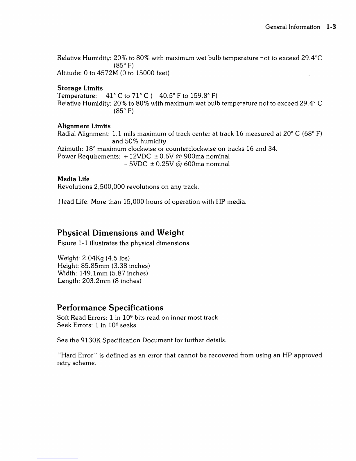
Physical
Dimensions
and Weight
Figure 1-1 illustrates
the
physical dimensions.
Weight:
2.04Kg
(4.5 lbs)
Height:
85.85mm
(3.38
inches)
Width:
149.1mm
(5.87
inches)
Length:
203.2mm
(8 inches)
Performance
Specifications
Soft
Read
Errors: 1 in
109 bits
read
on
inner
most
track
Seek
Errors: 1 in
106 seeks
See
the
9130K
Specification
Document
for further details.
"Hard
Error"
is
defined
as
an
error
that
cannot
be
recovered
from using
an
HP
approved
retry
scheme.
1-4
General
8.37
(212.72)
Information
~-----(l~~6)---
3.12
(79.37)
1.37
(34.92)
SEE
NOTE
*1.87*
*(47.62)*
3
~===~=====::::~~
14--------
6.12(155.57)
*5.87(149.22)*
__
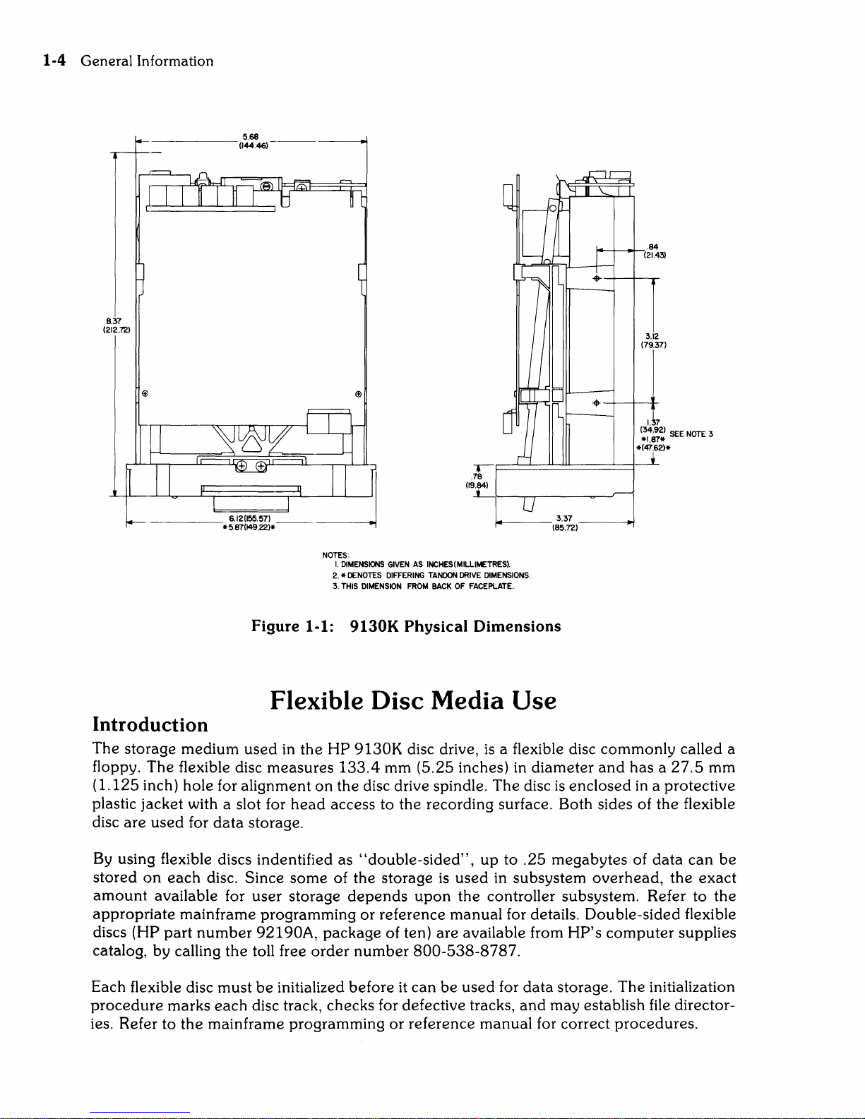
Figure 1-1:
Flexible
Introduction
The
storage
floppy. The flexible disc
(1.125 inch) hole for alignment
plastic jacket with a slot for
are
disc
By
using flexible discs indentified as
stored
amount
appropriate
(HP
discs
catalog, by calling
medium
used
in the
measures
head
used
for
data
storage.
on
each
disc. Since
some
available for user storage
mainframe programming
part
number
the
92190A,
toll free
~I
~
NOTES:
I.
2. * DENOTES
3.
HP
on
the
DIMENSIONS
THIS
133.4
GIVEN
AS
INCHES(MILLIMETRES).
DIFFERING
DIMENSION
9130K
Disc
9130K
TANDON
FROM
BACK
Physical Dimensions
Media
disc drive,
mm (5.25 inches) in diameter
disc drive spindle. The disc
DRIVE
OF
FACEPLATE.
14---
DIMENSIONS.
Use
is
a flexible disc commonly called a
337
=]
(85.72)
and
is
enclosed in a protective
access to the recording surface. Both sides of
"double-sided",
of the storage
depends
or
reference manual for details. Double-sided flexible
package
order
number
upon
of ten) are available from
800-538-8787.
up
to
.25
megabytes of
is
used
in subsystem
overhead,
the controller subsystem. Refer to
HP's
has a
the
data
computer
27.5
mm
flexible
can
the
exact
the
supplies
be
Each flexible disc must
procedure
ies. Refer to
marks
the
mainframe programming
be
initialized before it
each
disc track, checks for defective tracks,
can
be
used
for
data
storage.
and
may establish file director-
or
reference manual for correct procedures.
The
initialization
General Information 1-5
CAUTION
ONLY HP
MEDIA
IS
APPROVED FOR USE
IN
THE 9130K
FLEXIBLE DISC
DRIVE.
USE OF OTHER
MEDIA
MAY
RESULT
IN
PREMATURE DISC FAILURE OR
DAMAGE
TO THE
DRIVE.
HP
MEDIA
WILL
ALWAYS
HAVE
AN/HP
LABEL
ON
IT.
HP RIGOROUSLY TESTS EACH BATCH OF
MEDIA
FOR
ERROR
RATE
AND
WEAR
PERFORMANCE
IN
ADDITION TO
INITIAL
VENDOR QUALIFICATION.
ONLY
IN
THIS
WAY
CAN
HP ASSURE RELIABLE
MEDIA
PERFORMANCE.
THE USE OF NON-HP
MEDIA
FOR SINGLE USE APPLICA-
TlONS SUCH
AS
DATA
INTERCHANGE WILL PROBABLY
NOT
DAMAGE
THE
DRIVE
OR
MEDIA
BUT,
IF
EXTENDED
USE
IS
ANTICIPATED, THE
DATA
MUST
BE
TRANSFERRED
TO HP
MEDIA.
EXTENDED USE OF NON-HP APPROVED
MEDIA
WILL
VOID
WARRANTY
AND
SERVICE CONTRACTS
ON
THE INSTRU-
MENTS.
Operating
Cleanliness
To
prevent
potential
damage
or
data
loss, it is
extremely
important
to
maintain
the
cleanli-
ness
of
the
disc
and
air within
the
disc drive.
The
disc drive
should
not
be
operated
in
an
environment
in which dust,
smoke,
moisture, oil
or
chemical
vapor
or
other
foreign
matter
are
present.
Also,
be
sure
to
strictly follow
the
disc
handling
gUidelines.
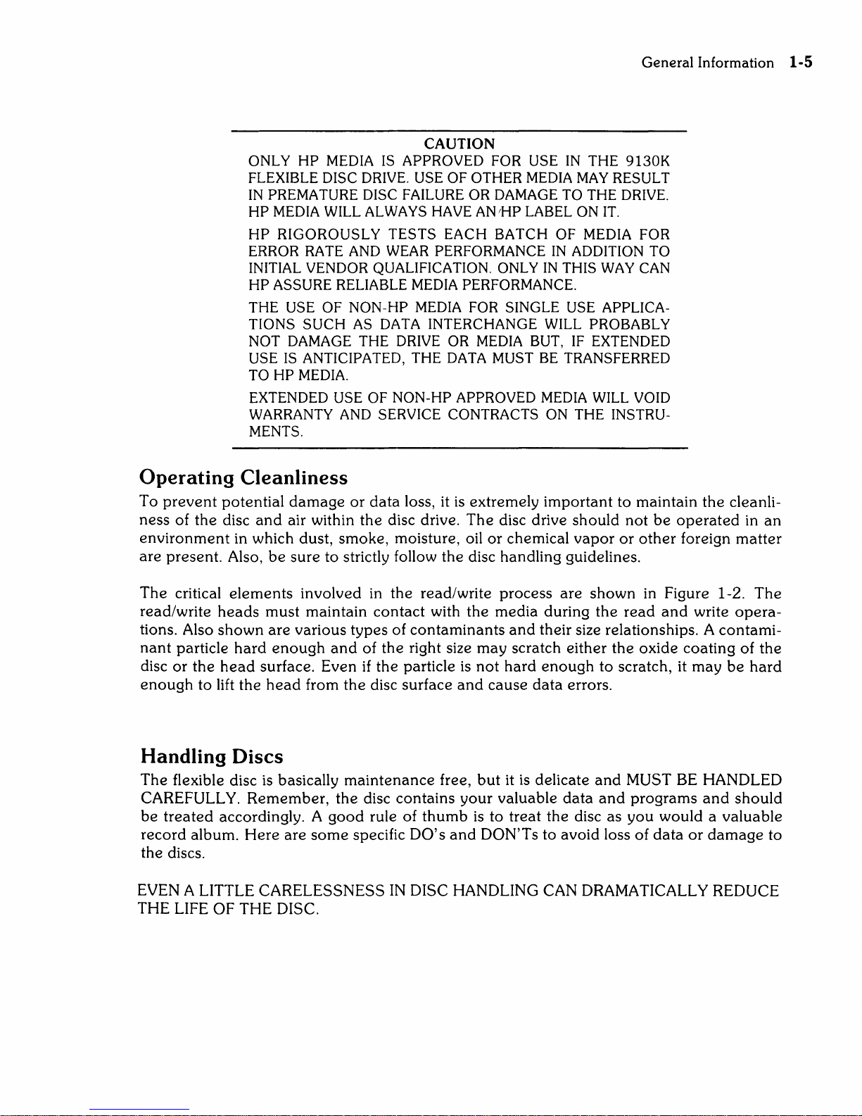
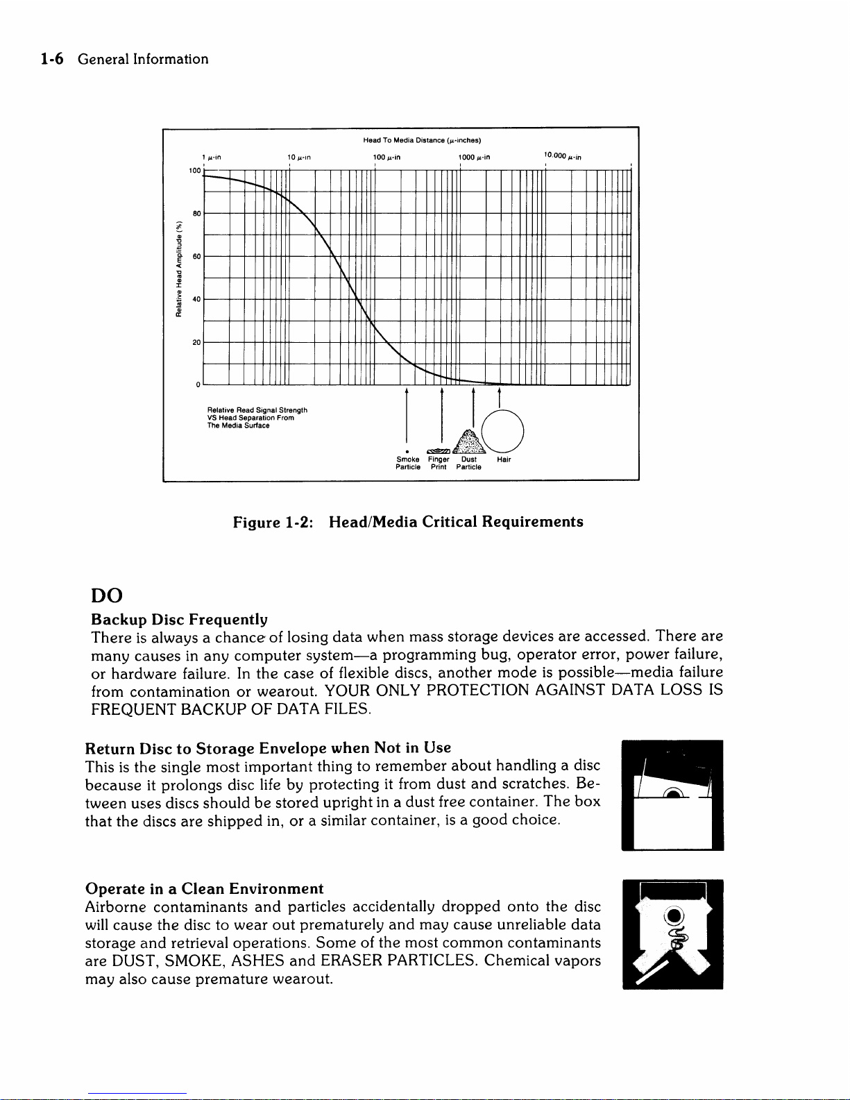
The
critical
elements
involved in
the
read/write
process
are
shown
in Figure 1-2.
The
read/write
heads
must
maintain
contact
with
the
media
during
the
read
and
write
opera-
tions. Also
shown
are
various
types
of
contaminants
and
their size relationships. A
contami-
nant
particle.
hard
enough
and
of
the
right size
may
scratch
either
the
oxide
coating
of
the
disc
or
the
head
surface. Even
if
the
particle is
not
hard
enough
to
scratch, it
may
be
hard
enough
to
lift the
head
from
the
disc
surface
and
cause
data
errors.
Handling
Discs
The
flexible disc
is
basically
maintenance
free,
but
it
is
delicate
and
MUST BE HANDLED
CAREFULLY.
Remember,
the
disc
contains
your
valuable
data
and
programs
and
should
be
treated
accordingly. A
good
rule of
thumb
is
to
treat
the
disc
as
you
would a valuable
record
album.
Here
are
some
specific
DO's
and
DON'Ts
to
avoid
loss of
data
or
damage
to
the
discs.
EVEN A LITTLE
CARELESSNESS
IN
DISC HANDLING CAN DRAMATICALLY REDUCE
THE LIFE
OF
THE
DISC.
1-6 Generallnformation
100
80
!
~
60
«
'C
os
Q)
J:
Q)
~
40
Qi
II:
20
1
win
r--
r-
r-I'-o
"
'\
Relative Read Signal Strength
VS
Head Separation From
The Media
Surface
\
\
1\
~
Head To Media Distance
(winches)
100W
in
1000
win
I
I
I\.
,,~
........
"
"'t--
1
t
~~
~:;;;~.;~.~.
.
..-AO
Smoke Finger Dust Hair
Particle Print Particle
10.0001'-in
Figure
1-2:
Head/Media
Critical
Requirements
DO
Backup
Disc
Frequently
There
is
always a chance' of losing
data
when
mass
storage
devices
are
accessed.
There
are
many
causes
in
any
computer
system-a
programming
bug,
operator
error,
power
failure,
or
hardware
failure. In
the
case
of flexible discs,
another
mode
is
possible-media
failure
from
contamination
or
wearout.
YOUR ONLY PROTECTION AGAINST DATA
LOSS
IS
FREQUENT BACKUP
OF
DATA FILES.
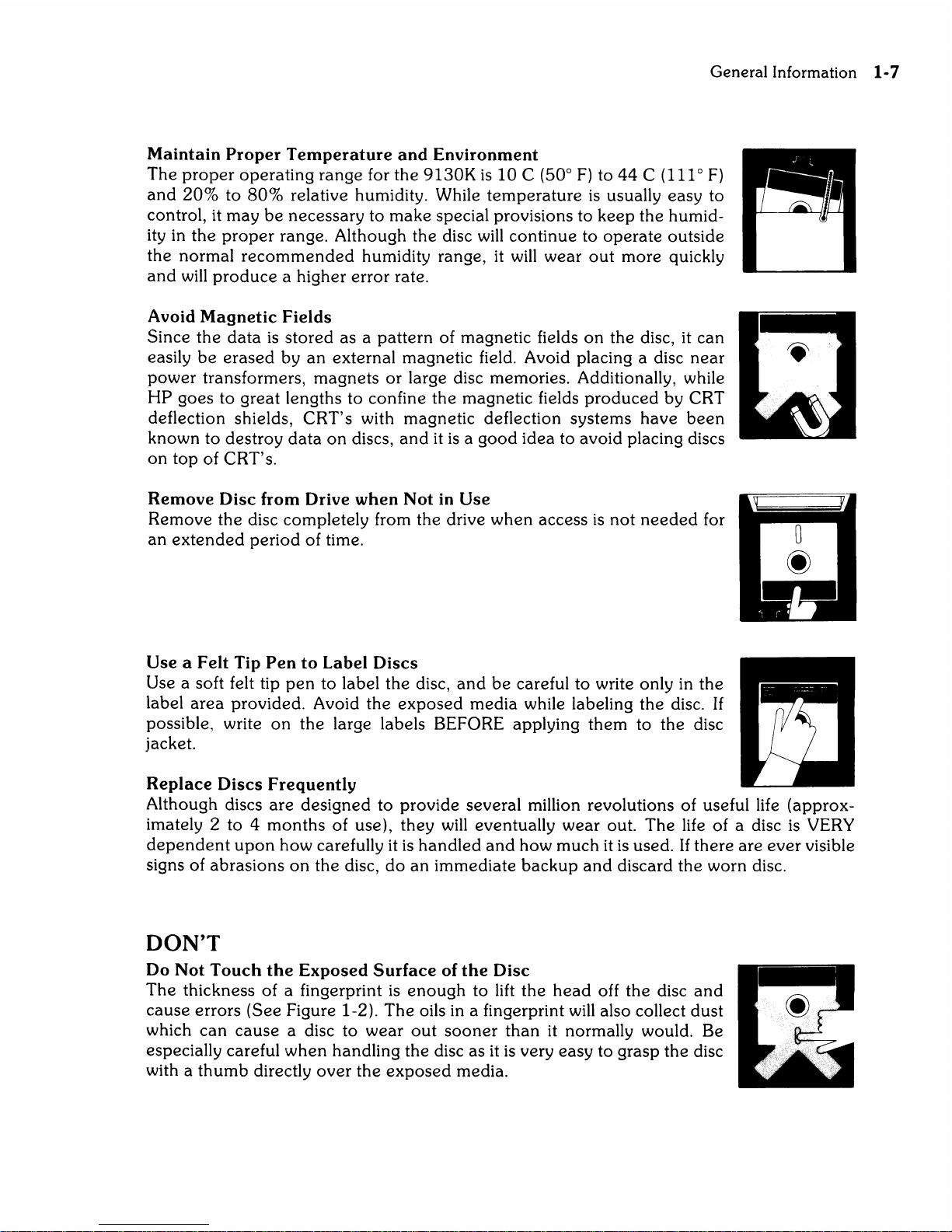
Return
Disc
to
Storage
Envelope
when
Not
in
Use
This
is
the
single
most
important
thing to
remember
about
handling a disc
because
it
prolongs
disc life by protecting it from
dust
and
scratches. Be-
tween
uses
discs
should
be
stored
upright in a
dust
free container.
The
box
that
the
discs
are
shipped
in,
or
a similar container,
is a good
choice.
Operate
in a
Clean
Environment
Airborne
contaminants
and
particles accidentally
dropped
onto
the
disc
will
cause
the
disc to
wear
out
prematurely
and
may
cause
unreliable
data
storage
and
retrieval
operations.
Some
of
the
most
common
contaminants
are
DUST, SMOKE, ASHES
and
ERASER PARTICLES. Chemical
vapors
may
also
cause
premature
wearout.
General Information
1-7
Maintain
Proper
Temperature
and
Environment
The
proper
operating
range
for
the
9130K
is
10
C (500 F)
to
44
C (1110 F)
and
20%
to
80%
relative humidity. While
temperature
is
usually
easy
to
control, it
may
be
necessary
to
make
special provisions to
keep
the
humid-
ity in
the
proper
range. Although
the
disc
will
continue
to
operate
outside
the
normal
recommended
humidity range,
it
will
wear
out
more
quickly
and
will
produce
a higher
error
rate.
Avoid
Magnetic
Fields
Since
the
data
is
stored
as a pattern
of magnetic fields
on
the
disc, it
can
easily
be
erased
by
an
external
magnetic field. Avoid placing a disc
near
power
transformers,
magnets
or
large disc memories. Additionally, while
HP
goes
to
great
lengths to confine
the
magnetic fields
produced
by CRT
deflection shields,
CRT's
with
magnetic
deflection
systems
have
been
known
to
destroy
data
on
discs,
and
it
is a good
idea
to avoid placing discs
on
top
of CRT's.
Remove
Disc
from
Drive
when
Not
in
Use
Remove
the
disc completely from
the
drive
when
access
is
not
needed
for
an
extended
period
of time.
Use a Felt
Tip
Pen
to
Label
Discs
Use a soft felt tip
pen
to label
the
disc,
and
be
careful to write only in
the
label
area
provided.
Avoid
the
exposed
media
while labeling
the
disc.
If
possible, write
on
the
large labels BEFORE applying
them
to
the
disc
jacket.
Replace
Discs
Frequently
j l
~
Although discs
are
designed
to provide several million revolutions of useful life
(approx-
imately 2
to 4 months
of
use),
they
will eventually
wear
out.
The
life of a disc
is
VERY
dependent
upon
how carefully it
is
handled
and
how
much
it
is
used.
If
there
are
ever
visible
signs of
abrasions
on
the
disc,
do
an
immediate
backup
and
discard
the
worn disc.
DON'T
Do
Not
Touch
the
Exposed
Surface
of
the
Disc
The
thickness of a fingerprint
is
enough
to lift
the
head
off
the
disc
and
cause
errors
(See
Figure 1-2).
The
oils in a fingerprint will also collect
dust
which
can
cause
a disc to
wear
out
sooner
than
it normally would. Be
especially careful
when
handling
the
disc as it
is
very
easy
to grasp
the
disc
with a
thumb
directly
over
the
exposed
media.
1-8
General
Information
Do
Not
Bend
or
Fold
the
Disc
The
disc
is
flexible
but
will
not
operate
if
it
is
creased.
Using ball
point
pens,
rubber
bands,
paper
clips, etc.
can
crease
the
disc.
Do
Not
Try
to
Clean a Disc
The
inside
surface
of
the
disc
jacket
is
covered
with a special material
that
cleans
the
disc
as
it
rotates. Any
other
method
of
cleaning
may
cause
solvent
damage
to
the
media
or
scratch
the
disc,
causing
loss of data.
If
a disc
becomes
dirty
or
scratched,
immediately
copy
the
data
to a
new
disc
and
dispose
of
the
old disc.
Disc
Loading
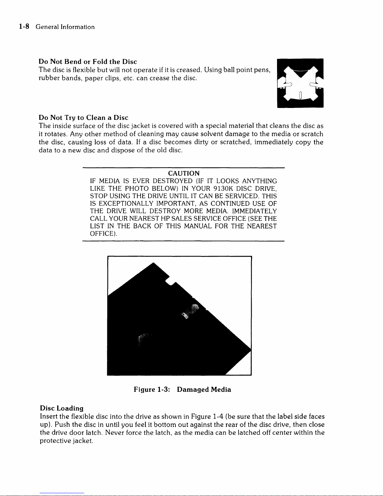
CAUTION
IF
MEDIA
IS
EVER
DESTROYED
(IF
IT
LOOKS ANYTHING
LIKE
THE PHOTO BELOW)
IN
YOUR 9130K DISC
DRIVE,
STOP USING THE
DRIVE
UNTIL
IT
CAN
BE
SERVICED. THIS
IS
EXCEPTIONALLY IMPORTANT,
AS
CONTINUED
USE
OF
THE
DRIVE
WILL
DESTROY
MORE
MEDIA.
IMMEDIATELY
CALL YOUR NEAREST HP SALES SERVICE OFFICE (SEE THE
LIST
IN
THE
BACK
OF
THIS
MANUAL
FOR THE NEAREST
OFFICE).
Figure
1-3:
Damaged
Media
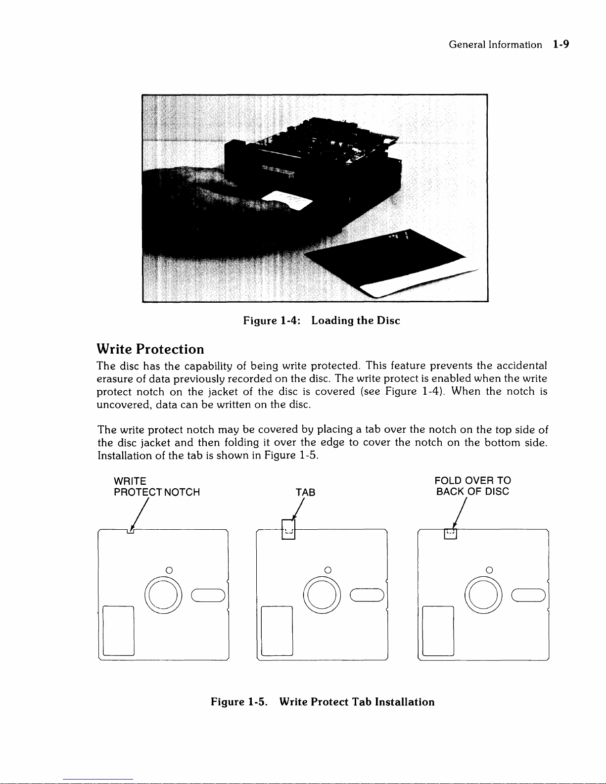
Insert
the
flexible disc into
the
drive as
shown
in Figure
1-4
(be
sure
that
the
label side faces
up).
Push
the
disc in until
you
feel it
bottom
out
against
the
rear
of
the
disc drive,
then
close
the
drive
door
latch.
Never
force
the
latch,
as
the
media
can
be
latched
off
center
within
the
protective
jacket.
General
Information
1-9
Figure 1-4: Loading
the
Disc
Write Protection
The
disc
has
the
capability of
being
write protected. This feature
prevents
the
accidental
erasure
of
data
previously
recorded
on
the
disc.
The
write
protect
is
enabled
when
the
write
protect
notch
on
the
jacket
of
the
disc
is
covered
(see Figure 1-4).
When
the
notch
is
uncovered,
data
can
be
written
on
the
disc.
The
write
protect
notch
may
be
covered
by placing a
tab
over
the
notch
on
the
top
side
of
the
disc
jacket
and
then
folding it
over
the
edge
to
cover
the
notch
on
the
bottom
side.
Installation of
the
tab
is
shown
in Figure 1-5.
WRITE
PROTECT NOTCH
.,,--------,L
o
TAB
o
Figure 1-5. Write Protect Tab Installation
FOLD OVER TO
BACK OF DISC
o

Chapter
2
Interface Information
Introduction
This
chapter
provides
the
interface information for
the
9130K
Flexible Disc Drive.
The
information
provided
in this
chapter
includes
connector
locations
and
pin-outs, signal line
descriptions
and
typical interface driver
and
receiver circuits.
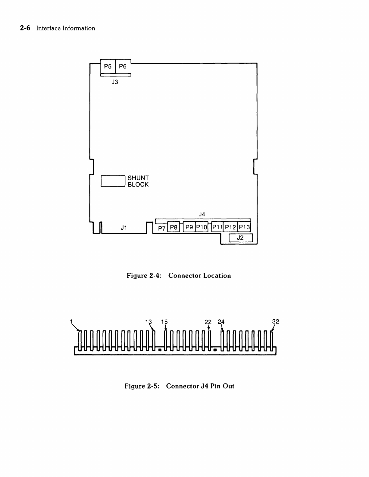
Interface
The
flexible disc drive
110
connector
(J1)
is
located
on
the
rear
edge
of
the
drive electronics
board.
The
34
pin
edge
connector
mates
with
the
HP
connector
part
number
1251-3916.
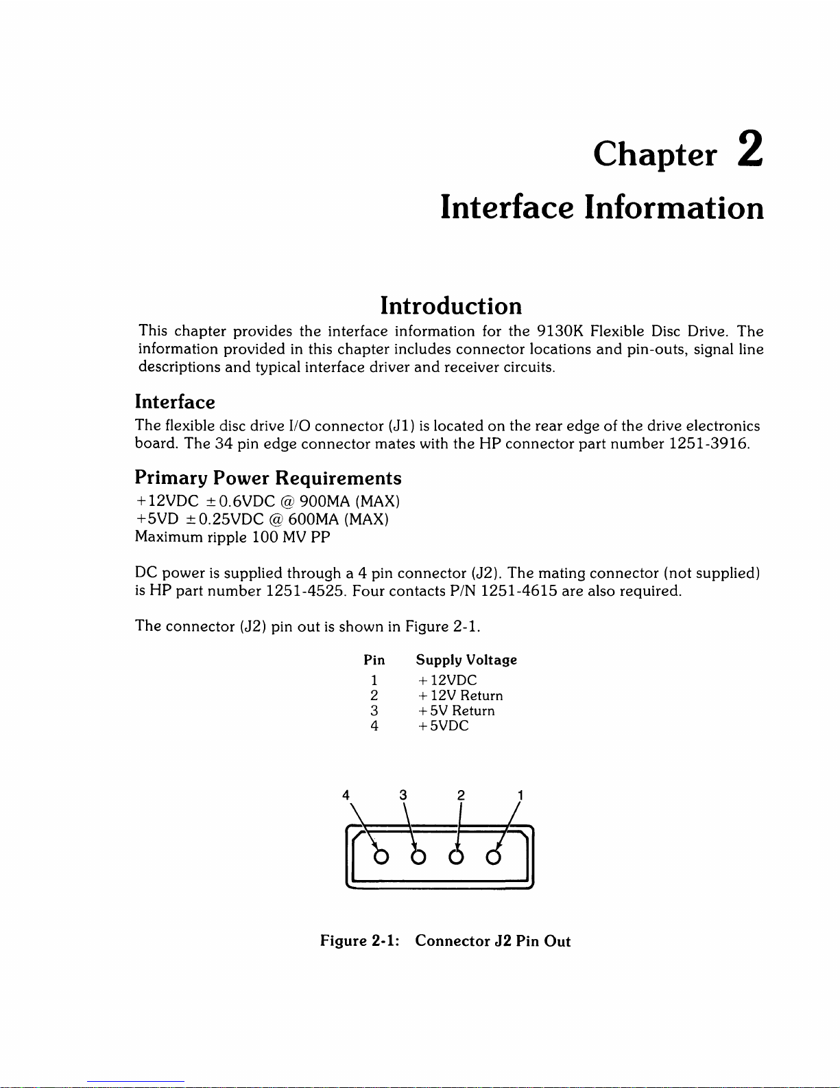
Primary
Power
Requirements
+12VDC
±0.6VDC
@ 900MA
(MAX)
+5VD ± 0.25VDC @ 600MA
(MAX)
Maximum ripple
100
MV
PP
DC
power
is
supplied
through
a 4 pin
connector
(J2).
The
mating
connector
(not supplied)
is
HP
part
number
1251-4525.
Four
contacts
PIN
1251-4615
are also required.
The
connector
(J2) pin
out
is
shown
in Figure 2-1.
Pin
Supply
Voltage
1 + 12VDC
2 + 12V Return
3
+5V
Return
4
+5VDC
Figure
2-1:
Connector
J2
Pin
Out
2-2
Interface Information
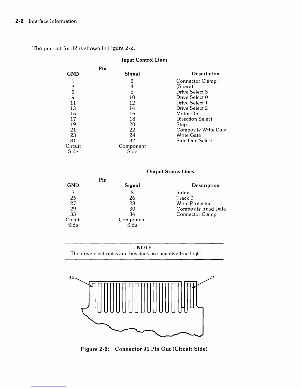
The
pin-out
for
J2
GND
1
3
5
9
11
13
15
17
19
21
23
31
Circuit
Side
is
shown
in Figure 2-2.
Input Control Lines
Pin
Signal
Component
2
4
6
10
12
14
16
18
20
22
24
32
Side
Description
Connector
(Spare)
Drive Select 3
Drive Select 0
Drive Select 1
Drive Select 2
Motor On
Direction Select
Step
Composite Write Data
Write
Side
Gate
One
Clamp
Select
Output
Pin
GND
7
25
27
29
33
Circuit
Side
The
drive electronics
34 2
Signal
8
26
28
30
34
Component
Side
NOTE
and
bus lines use negative true logic.
Status
Lines
Description
Index
0
Track
Write
Protected
Composite Read Data
Connector
Clamp
Figure 2-2: Connector
Jl
Pin Out (Circuit
Side)

Interface
Information
2-3
Signal
Line Description
Input Control Lines
Drive
There
disc drives
When
the drive
The drive select line must remain stable in
command
When
status lines
There
The disc drive
electronics circuit board.
chaining a maximum of
if
select lines are low simultaneously.
Select
more
Lines
are
four drive select lines which are
attached
the
logic level
will
is
the
logic level
are
is
also a
than
respond
completed.
one
to the controller.
on
the
to
step
on
the drive select lines
disabled.
user
installed option
address
drive
is
three
is
drive select line
or
Read/Write commands.
determined
The
drive select lines 1 through 3 provide a
disc drives to a controller. An undefined
assigned the
jumper
by a select
same
used
is
available
for selecting
low, the disc drive electronics
the
low state until the
are
high, the input control lines
to
code
select
code
and
de-selecting
step
utilize a fourth drive select line.
shunt
block located
or
if
more
operation
than
one
are
enabled
or
Read/Write
and
on
means
may
one
of the drive
of
three
and
output
the
drive
of daisy
result
Motor On
A low logic level
250
msec.
Direction
When a disc drive
appearing
determined by
issued. A high logic level
direction of motion
direction select line results in the inward direction (step in) of motion toward
ensure
To
prior to the
motion
Consecutive trailing
The drive electronics
•
The
• The direction select
•
The
When
Select
on
proper
is
initiated
write gate line
drive
on
this line causes the drive motor to accelerate
this line goes high,
and
Step
Lines
is
selected, a low pulse greater
the
step
line initiates
the
logic level
is
outward (step-out) away from the
positioning, the direction select line should
step
pulse
on
the
edges
will
is
is
not
selected.
appearing
on
the direction select line when the
and
remain stable until 1
trailing
of
step
ignore
low.
is
high
the
drive
motor
head
assembly motion. The direction of this motion
on
the direction select line
edge
of the step pulse.
pulses should not
step
and
pulses
the
if
any of the following conditions exist:
head
position
and
decelerates to a stop.
than 1 /-Lsec.
center
/-Lsec.
be
is
after
less
then
at track
of the disc. A logic low
but
when
step
be
stable 1 msec. minimum
the
step
5 msec. apart.
O.
stabilize in less
less
pulse
pulse.
than
the
step
is
the
disc center.
The
2 msec.
pulse
issued
on
access
than
is
is
the
the
2-4
Interface
Information
Composite
When
that
control
be
must
Write Gate
When
disabled). This line
is
Data
Changes
the
write
If
a write
of
the
Side
One
The
Side
transfer.
A high logic level selects
read/write
Write
the
disc drive
the
enabled
this line
written
write gate
is
of
state
gate
line
protected
Select
One
head.
Data
is
switching of
by
the
low,
the
enables
under
Select
the
on
the
is
high, all write electronics are disabled.
disc
and
side
line defines which side of a two sided disc
selected, this line provides
the
write
current
write gate line.
write electronics are
write
current
control of the composite write
write
gate
line
is
installed;
one
the
side'
the
select lines.
'0"
to flow in
should
write electronics are disabled irrespective of
read/write
in
enabled
occur before
head
the
bit serial composite write
the
selected head.
for writing
the
selected read/write head.
data
line
the
first write
and
a low logic level selects
data
and
is
The
used
data
pulses
write electronics
(read electronics
side
one
select line.
data
pulse.
for information
the
the
When
side 1
are
state
Output
Index
An
index
begining of a track.
The
remains low for
Track 0
This line indicates to the controller
track a signal remains low until
anding
Write Protected
This line goes low
When
may
an
error
Composite
Data
flux transition
Status
pulse occurs
leading
the
be
and
edge
the
track a switch
write
performed.
condition will
Read
clock transitions are transmitted
Lines
of this signal
the
duration of
when
protect
If
the
Data
detected
once
every revolution of the disc (200 msec. nominal) to indicate
and
phase
the
disc
line
goes
controller issues a write
be
reported
by
the
is
used
the
the
is
high,
head
to insure
index
that
the
head
a of
the
write
protected
the
to
the
provides a logic low pulse of 1
data
accuracy during format.
pulse.
read/write
is
moved
stepper
write electronics are
command
host system.
on
this line
head
from track
motor
to disable the write electronics.
when
control.
when
the
is
enabled
positioned
O.
This
is
and
the disc
disc drive
J-lsec.
±.
The
index
on
track
O.
accomplished
write
operations
is
write
protected
is
selected. Each
25
on
this line.
the
line
The
by
Interface
Information
2-5
POWERON
MOTORON
DRIVE
VALlDTRKOO
AN D WRT. PROT.
OUTPUT
SELECT
DIRECT
SELECT
WR ITE
VALID
READ
10
N
DATA
DATA
~~------------------------~/I
-.l
----+--i
----+--+--t
---+--+--
-----t---t--_
~F~_1_0_0_M_S_M_I_N
~
250
...........
____________
MSEC
MAX
~/~/
______
__
I.-1 jJ.sMIN
__
-+--+-_-I-.JIO:....I..U.JiI~'-+-
___
-+--+-
__
2_0_M_S_M_IN
___
___
~
"""'"
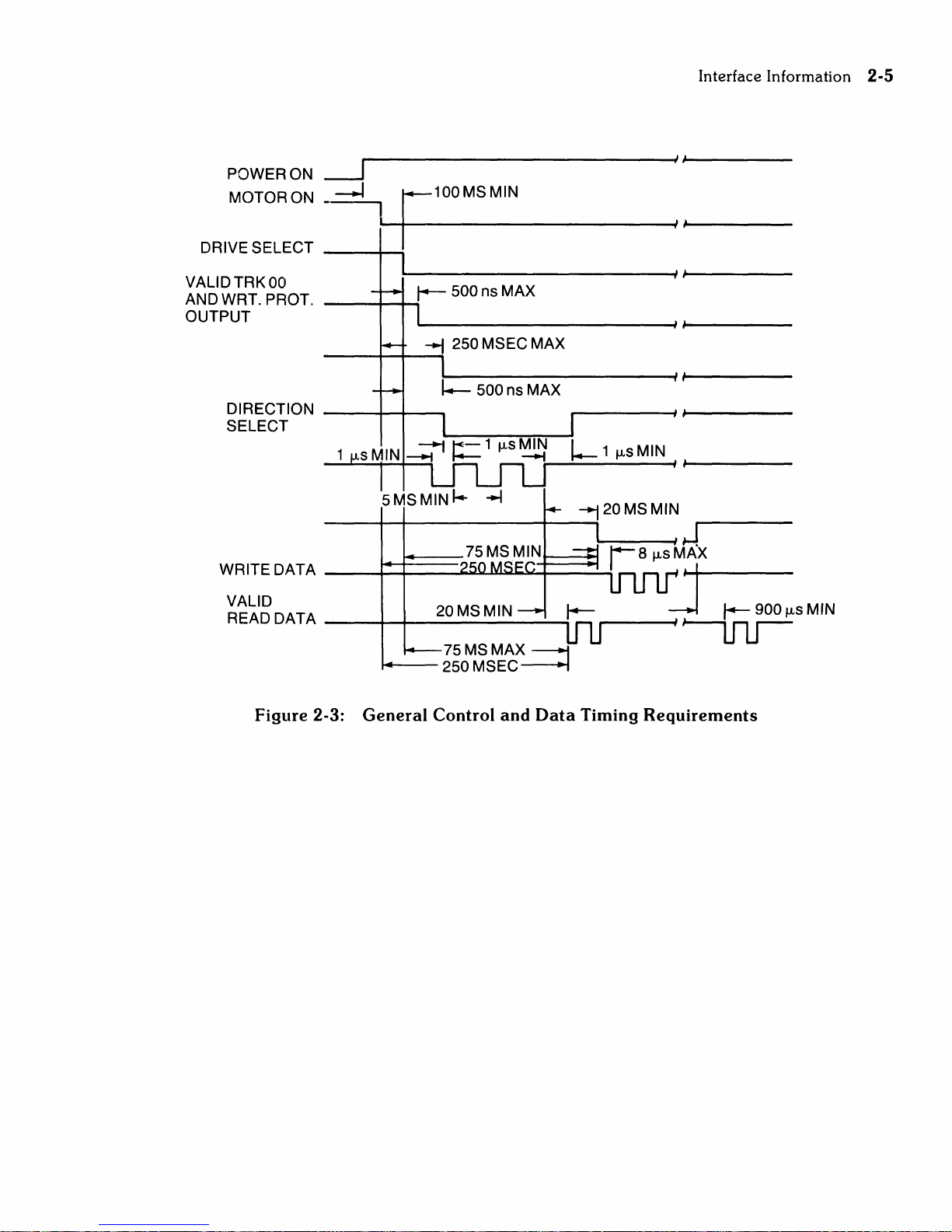
Figure
2-3:
14----
General
75 MS
250
MSEC~
Control
MAX
and
---1
Data
Timing
Requirements
2-6
Interface
Information
J3
SHUNT
~_--'.
I
BLOCK
Figure
Figure
2-4:
2-5:
Connector
Connector
J4
Location
J4
Pin
:
Out
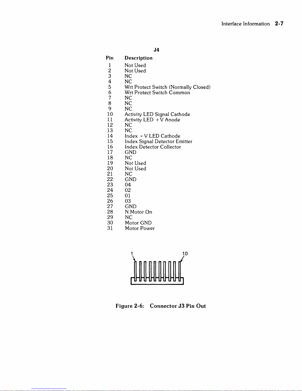
Pin
1
2
Description
Not
Used
Not
Used
3 NC
4 NC
5 Wrt
6 Wrt
Protect
Protect
7 NC
8 NC
9 NC
10 Activity LED
11
Activity LED + V
12 NC
13 NC
14
15
16
Index
Index
Index
+ V LED
Signal
Detector
17 GND
18 NC
19
20
Not
Not
Used
Used
21 NC
22 GND
23 04
24
25
02
01
26 03
27 GND
28 N
29
30
31
Motor
NC
Motor
Motor
On
GND
Power
J4
Switch (Normally Closed)
Switch
Common
Signal
Detector
Cathode
Anode
Cathode
Collector
Emitter
Interface
Information
2-7
Figure
2-6:
Connector
J3
10
Pin
Out

2-8 Interface Information
J3
Pin
1
2 Wrt
3
4 Wrt
5 Erase Coil
6 Erase Coil
7 Wrt
8
9 Wrt
10
Description
Head
Shield
Head
Center
Head
Head
Center
Head
Shield
1 (R/W Coil)
Tap
1 (R/W Coil)
2 (R/W Coil)
Tap
2 (R/W Coil)
J
10--
1~
J1
~
~
a I I
~
~
~
I
--
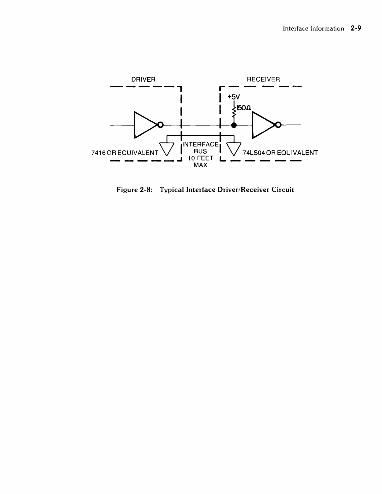
Typical
The
output
True
Interface
control
= Logical Zero =
False = Logical
Figure
2-7:
Pin
1 +
2 -
3 + Motor
4 Motor
5 NC
6 NC
7 N Motor
8 NC
9 GND
10
Drive/Receiver
lines
have
the
following electrical specifications:
Vout
+ O.4V (max.) @
One = Vout + 2.4V
Servo
Description
+ 12V
(min.)
Electronics
Tach
Tach
Power
Return
On
Circuits
lout
48ma
lout
250ma
Board
(MAX)
(max.)
Jl
Interface
Information
2-9
-----,
74160R
_____
DRIVER
INTERFACEI
EQUIVALENT BUS
Figure
2-8:
Typical
I
-'
10 FEET L
MAX
Interface
RECEIVER
74LS040R
Driver/Receiver
EQUIVALENT
Circuit

Chapter 3
Theory
of
Operation
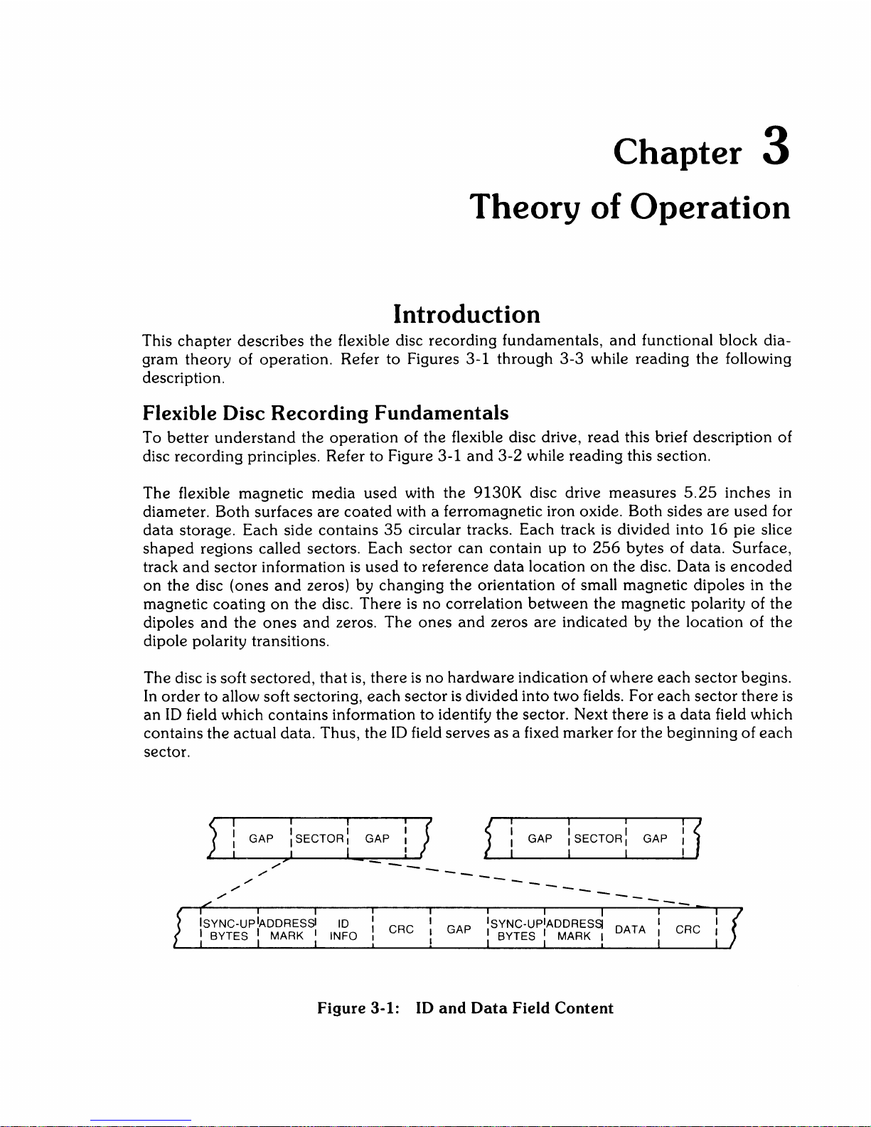
Introduction
This
chapter
describes
the
flexible disc recording fundamentals,
and
functional block dia-
gram theory of operation. Refer to Figures 3-1 through 3-3 while reading
the
following
description.
Flexible
Disc
Recording Fundamentals
To
better
understand
the
operation
of
the
flexible disc drive,
read
this brief description of
disc recording principles. Refer to Figure 3-1
and
3-2
while reading this section.
The flexible magnetic
media
used
with the
9130K
disc drive
measures
5.25
inches in
diameter. Both surfaces
are
coated
with a ferromagnetic iron oxide. Both sides
are
used
for
data
storage. Each side contains
35
circular tracks. Each track
is
divided into
16
pie slice
shaped
regions called sectors. Each sector
can
contain
up
to
256
bytes of data. Surface,
track
and
sector information
is
used
to reference
data
location
on
the disc. Data
is
encoded
on
the disc (ones
and
zeros) by changing
the
orientation of small magnetic dipoles in
the
magnetic coating
on
the disc. There
is
no
correlation
between
the magnetic polarity of
the
dipoles
and
the
ones
and
zeros.
The
ones
and
zeros are indicated by the location of
the
dipole polarity transitions.
The disc
is
soft sectored,
that
is,
there
is
no
hardware indication of
where
each
sector begins.
In
order
to allow soft sectoring,
each
sector
is
divided into two fields. For
each
sector
there
is
an
ID
field which contains information to identify the sector. Next
there
is a data
field which
contains the actual data. Thus,
the
ID
field serves as a fixed marker for the beginning of
each
sector.
",..
,/
,/
---
---
---
---
---
Figure 3-1:
ID
and
Data
Field Content
3-2
Theory of Operation
The
makeup
of
the
ID
and
DATA fields is similar.
Both
fields
begin
with a series of
synchro-
nization bytes.
These
bytes
allow
the
decoder
circuitry of
the
controller time
to
synchronize
itself with
the
data
on
the
disc. Following
the
synchronizing bytes, is
the
address
mark
byte
which indicates
that
the
beginning
of
an
ID
or
DATA field
has
been
located.
The
first bit
of
an
address
mark
is
the
opposite
polarity of
the
last bit of
the
previous
synchronizing byte.
This
feature
simplifies
detection
of
address
marks.
A series of
information
bytes
follows
the
address
mark. In
an
ID
field,
these
bytes
indicate
the
logical cylinder,
head
and
sector
address.
In
a DATA field,
these
bytes
are
the
data
being
stored
in
the
sector.
At
the
end
of
each
field
are
two cyclic
redundance
check
(CRC) bytes. This
check
word
(16
bits long) allows
detection
of
most
errors
that
occur
in
the
data
storage
and
recovery
of
information from a disc.
There
are
two
gaps
following
each
field
on
a track.
The
gaps
allow for variations in disc
rotational
speed,
index
detector
alignment
variations
and
time for
the
hardware
to
prepare
for
the
next
field.
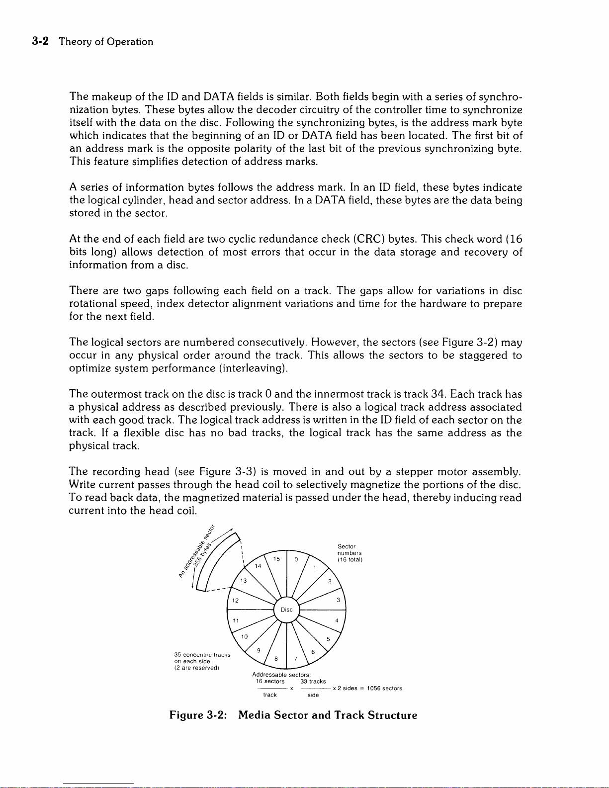
The
logical
sectors
are
numbered
consecutively. However,
the
sectors (see Figure
3-2)
may
occur
in
any
physical
order
around
the
track. This allows
the
sectors
to
be
staggered
to
optimize
system
performance
(interleaving).
The
outermost
track
on
the
disc
is
track 0
and
the
innermost
track
is
track
34.
Each
track
has
a physical
address
as
described
preViously.
There
is
also a logical track
address
associated
with
each
good
track.
The
logical track
address
is written in
the
ID
field of
each
sector
on
the
track.
If
a flexible disc
has
no
bad
tracks,
the
logical track
has
the
same
address
as
the
physical track.
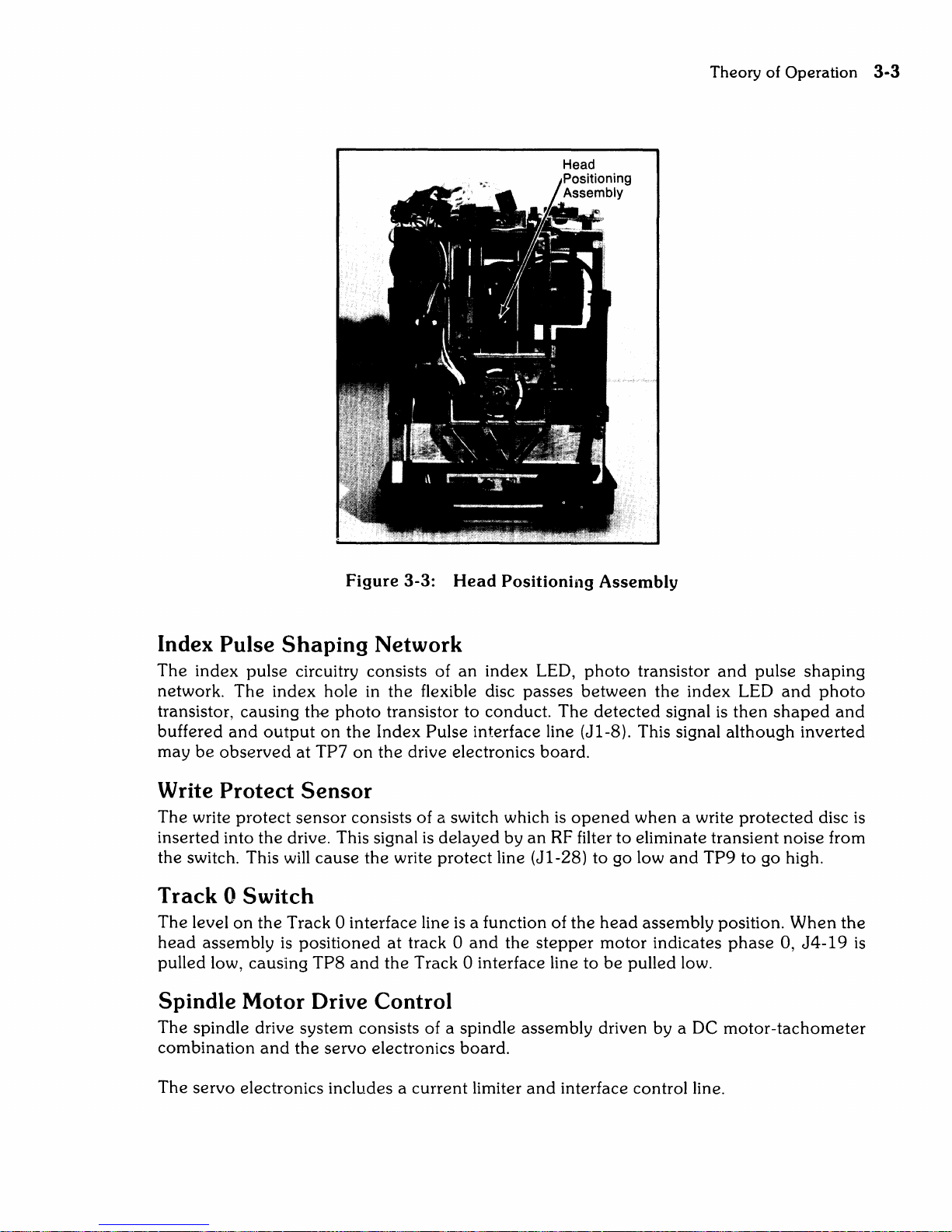
The
recording
head
(see Figure
3-3)
is
moved
in
and
out
by a
stepper
motor
assembly.
Write
current
passes
through
the
head
coil
to
selectively magnetize
the
portions
of
the
disc.
To
read
back
data,
the
magnetized
material
is
passed
under
the
head,
thereby
indUcing
read
current
into
the
head
coil.
35 concentric tracks
on each side
(2
are reserved)
Addressable sectors:
16 sectors 33 tracks
Sector
numbers
(16
total)
--
x
~~-
x 2 sides = 1056 sectors
track side
Figure
3-2:
Media
Sector
and
Track
Structure
Theory of Operation
3-3
Figure 3-3: Head Positioning
Assembly
Index Pulse
Shaping
Network
The
index
pulse circuitry consists of
an
index
LED,
photo
transistor
and
pulse
shaping
network.
The
index
hole in
the
flexible disc
passes
between
the
index
LED
and
photo
transistor, causing
the
photo
transistor to conduct.
The
detected
signal
is
then
shaped
and
buffered
and
output
on
the
Index Pulse interface line (J 1-8). This signal
although
inverted
may
be
observed
at
TP7
on
the
drive electronics board.
Write Protect
Sensor
The
write
protect
sensor
consists of a switch which
is
opened
when
a write
protected
disc
is
inserted into
the
drive. This signal
is
delayed
by
an
RF
filter to eliminate transient noise from
the
switch. This will
cause
the
write
protect
line
(Jl-28)
to go low
and
TP9
to go high.
Track 0
Switch
The
level
on
the
Track 0 interface line
is
a function of
the
head
assembly position.
When
the
head
assembly
is
positioned
at
track 0
and
the
stepper
motor
indicates
phase
0,
J4-19
is
pulled low, causing
TP8
and
the
Track 0 interface line to
be
pulled low.
Spindle Motor Drive Control
The
spindle drive system consists of a spindle assembly driven by a DC
motor-tachometer
combination
and
the
servo
electronics board.
The
servo electronics includes a
current
limiter
and
interface control line.
3-4
Theory
of
Operation
When
the
Drive Motor Enable line
is
low, the drive
motor
is
allowed to
come
up
to
speed.
This
speed
is
adjustable
by
potentiometer
R4 located
on
the servo electronics board.
A current sensing resistor, also
located
on
the
servo electronics
board
limits
the
motor
current to
900ma.
If
this limit
is
exceeded,
the
motor
is
disabled.
Head
Position
Control
The
head
position Control consists of a four
phase
stepper
motor
drive which
changes
one
phase
for
each
track
advancement
of
the
head
assembly.
In
addition to
the
logic for motion
control, a
gate
is
provided
to inhibit repositioning during a write operation.
Power On Circuit
This circuit detects
when
the
+5VDC
and
+ 12VDC are valid
and
prevents
writing/reading/
erasing/stepping until
such
time.
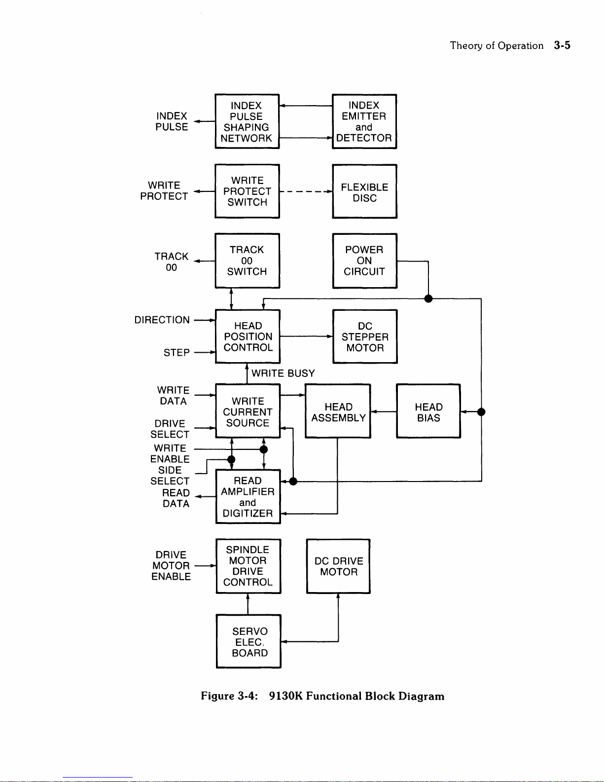
Data
Circuitry
All
signals
required
to control
the
data
circuitry are provided by
the
host system
and
are
shown
in
the
functional block diagram of Figure 3-4.
These
signals are as follows:
Drive
Select
Write Enable
Write Data
Side
Select
There
are
4 drive select lines
connected
to
the
data
electronics. A
shunt
block
determines
the drive
number.
The
drive
number
is
established by clipping
three
of
the
jumpers
on
the
shunt
block
or
adding a shunt
to
an
empty block.
When
the
selected drive select line
is
pulled low,
the
data
circuitry
is
enabled
and
the
drive
is
conditioned to
respond
to
step
or
read/write
commands.
Writing
Data
The
write electronics consists of
the
following circuits:
Write/erase
current
source
Waveform
generator
Trim
erase
current
source
Head
select logic
Bias
Source
The
read/write winding
on
the
head
is
center
tapped. During a write operation,
the
current
from
the
write
current
source
flows in
the
alternate halves of
the
winding
under
the
control
of
the
write waveform generator.
Before recording
can
begin, certain conditions must
be
satisfied.
The
conditions
required
before writing (i. e., unit ready) must
be
established by
the
host system
as
follows:
1.
Drive
speed
stabilization. This
will
exist
250ms
after starting
the
drive motor.
2.
Subsequent
to
any
step
operation,
the
positioner must
be
allowed to settle. This
requires
20ms
total after
the
last
step
pulse
is
initiated, i. e.,
5ms
for
the
step
motion
and
15ms
for settling.
INDEX
PULSE
~
INDEX
PULSE
SHAPING
NETWORK
INDEX
EMITTER
and
DETECTOR
WRITE WRITE FLEXIBLE
PROTECT
~
PROTECT ~ - - - -..... DISC
TRACK
00
DIRECTION
STEP
WRITE
DATA
DRIVE
SELECT
WRITE
ENABLE
SIDE
SELECT
READ
DATA
DRIVE
MOTOR
ENABLE
~
----
---
~
~
~
---+
SWITCH
TRACK POWER
00
ON
SWITCH CIRCUIT
,
HEAD
DC
POSITION
STEPPER
CONTROL
MOTOR
tWRITE
BUSY
~
WRITE
CURRENT
HEAD
f4---
ASSEMBLY
SOURCE
I+-
~
READ
AMPLIFIER
and
DIGITIZER
SPINDLE
MOTOR
DC DRIVE
DRIVE
MOTOR
CONTROL
f
SERVO
ELEC.
BOARD
HEAD
BIAS
Figure
3-4:
9130K
Functional
Block
Diagram
Theory of Operation
3-5
~.
 Loading...