

HP 9122D, 9122S Service Manual
HP
91220/5
Disc Drives
Prin
ted: APRIL 1
Printed
Service
in
Manual
U.
s.
part
988
A.
Manual
number:
5957-6559
Edition
E0488
2
P.O.
rL:'
a!~
HEWLETT
Box
39,
HEWLETT
PACKARD
-PACKARD
Boise,
Idaho
83707-0039

Notice
The
information
contained
in
':his
document
is
subject
to
change
without
notice.
HEWLETT-PACKARD
~lA](ES
NO
WARRANTY
OF
ANY
KIND
WITH
REGARD
TO
THIS
MATERIAL.
I;SCLUDI~G.
BliT
NOT
LI"lITED
TO,
THE
IMPLIED
"[ARRA!'iTIES
OF
~IERCHANTABILITY
A~D
lFITNESS
FOR A PARTICULAR
PURPOSE.
HEWLETT-PACKARD
shall
not
be liable for I!rrors
contained
herein
or
for
incidental
or
consequential
damages
in
connection
with
the
furnishing,
performance:
or
use
of
this
material.
HEWLETT-PACKARD
assumes
no
responsibility
for
the
use
or
reliability
of
its
software
on
equipment
that
is
not
furnished
by
HE'N'l.ETT-PACKARD.
This
document
contains
proprietary
information,
which
is
protected
by
copyright.
All
rights
are
reserved.
N'J
part
of
this
document
may
be
photocopied,
reproduced
or
translated
to
another
language
without
the
prior
written
consent
of
HEWLETT-PACKARD
Company.
Copyright @ 1984,
1988
by
HE\VLETT-PACKARD
b
Printing
History
New
editions
are
complete
revisions
of
the
manual.
Update
packages,
which
are
issued
between
editions,
contain
additional
and
replacement
pages
to
be
merged
into
the
manual
by
the
customer.
The
dates
on
the
title
page
change
only
when a new
edition
or a new
update
is published.
No
information
is
incor-
porated
into a reprinting
unless
it
appears
as a
prior
update;
the
edition
does
not
change
when
an
update
is
incorpora
ted.
A
software
code
may
be
printed
before
the
date;
this
indicates
the
version level of.
the
software
product
at
the
time
the
manual
or
update
was issued.
Many
product
updates
and
fixes do not,
require
manual
chang-
es
and,
conversely,
manual
corrections
may
be
done
without
accompanyi~gproduct
changes.
Therefore,
do
not
expect a one-to-one
correspondence
between
product
upd'ates
and
manual
updates.
Edition
1.
.......................................................
JUNE
1984
Edition 2 ........................................................
APRIL
1988
c

Contents
Cha
pter
1
Page
Genera)
Information
1-
1
Introduction
....................
'.' . . . . . . . . . . . . . . . .
..
. . . . . . . . . . . . . . . . . . . . . . . . . . . . . . . . . . . .
..
. . . . . . . . . . . . . .
..
1-1
Technical
Specifications
..........................................
'"
..
. . . . . . . . . . . . . .
.. . ..
...
. . . . .
..
. . . . .
.. ..
. . .
..
1-1
Power
Requirements
.....
: . . .
..
. . . . . . .
.. .. .. .. ..
. . . . . . . . . . . . . . . . . . . .
..
..
. .
..
. . . . . . . . . .
.. ..
. . . . . . . . .
..
. . . . .
... . ..
. . .
..
. . .
.. 1-2
Environmental
Specs
.............
: "
...... , ...............................................................................
1-
2
Equipment
Supplied
.........
, . .
..
..
. . . . . . . . . . . .
..
. .
..
. . . .
..
. . . . . . . . . . . . . . .
..
. . . . .
..
. . . . . . . . . . . . . .
..
. . .
..
. .
.. . ..
..
..
..
... 1-3
Unpacking
the
HP
9122D/S
Disc Drive
...................................................................
,
........
1-
3
Cleaning the Case. . . . . . . . . .
..
. .
..
..
.. . ..
. .
..
. . . .
.. .. . ..
..
. . .
..
. . . . . .
.. .. . ..
. . . .
..
. . .
..
. . . . . .
.. . ..
. . . . . . . . . . .
..
..
. . . . . .
..
. . . .
..
1 - 4
Chapter
2
Page
Installation
2-1
Configuring
Po'~er
......................................................................................................................
2-1
Setting
The Line Voltage Select Switch
..............................................................................
2-1
Fuses ...................... " .............
""
..................................................................... , ..........................
2-1
Power Cords
............................................................................................................................
, 2 - 1
Selecting the Device Address. . .
.. .. ..
. .
..
. .
.. . .. . ..
. . . . . .
..
..
. .
..
..
. . .
..
. .
..
. . . . .
..
. . . . . .
..
. . . .
.. ..
. . . . . . .
..
. .
..
.. ..
. .
.. .. ..
....
2 - 2
Disc
Compatibility
.................................................................................................................
2-3
Con troIs and Indica
tors.
.. ..
. . . . . .
.. . ..
. . .
..
. . . . . . . . . .
.. .. . ..
. . .
.. .. . .. .. . .. . .. .. . .. ..
. . . . . . . .
..
. . . . . . . . . . .
..
. . . . .
.. . ..
. . .
.. . ...
2 - 4
Media Moni
tor
...........
,.
. . .
..
. . . . . .
..
. .
..
. .
..
.. . ..
. .
.. ..
. .
..
. . . . .
..
. . . .
..
. . . . .
.. . .. ..
. . . . .
.. ..
. .
..
..
. . . . . . . .
..
. . . .
..
. . .
...
2 - 5
Power-On
Self test
.............................................................................................................
2-5
Write
Protect
Error
on
Initialization
....................................................................
2-5
Chapter
3
Page
Interface
Information
3-1
HP-IB
Interface
......................................................................................................
3-1
Instaiia tion. . . . . . . . . . . . . .
..
. . . . . . . . . . . . . . . . . . . . . . . . . . . . . . . . . . . . . . . . . . . . . . . . . . . . . . . . . . . . . .
..
. . . . . . . .
..
. . .
..
3 - 1
HP-IB
Interface Restrictions
............................................................
,
.............
'"
..........
3-1
Chapter
4
Trou
bleshooting
Page
4-1
Repair
Philosophy
....................................................................................................
4-1
Non
-Exchange
Assemblies
.........................................................................................
4-1
Exchange Assemblies
.........................................................................................
4-1
Controller
Electronics
and
Power Supply Assembly
..........................................................
4-
2
e

Contents
(continued)
5elftest
.........................
,
.........................................................................
4-4
Available Tests
........................................................................................
4-4
Selecting a 5elftest . . . . . . . . . . . . . . . . . . . . . . . . . . . . . . . . . . . . . . . . . . . . . . . . . . . . . . . . . . . . . . . . . . . . . . . . . . . . . . . . . .
..
4 - 5
Troubleshooting Procedures
..............................................................................
4-6
Fault
Isolation Procedures
.............................
'"
........... _ ...... , .......... _ ... _ ...... _ ...
4-6
Troubleshooting
Proc~~dures_
...
_ . _
.... _ ..
_ . _
..........................................................
4-6
Troubleshooting
Flowchart.
'.'
........................................................................
4-7
Using the
55/80
Exerciser
..
':
.......................................................................
4-11
DERRORS
...........................................................................................
4-11
Hints
on Using the 55/80 Exerciser
..................................................................
4-12
Adjustments
.................
'.'
................................
,
...... " .............. , .................
4·-14
PLL Adjustment
.....................................................................................
4·-14
Chapter
5
Assembly Access
Page
5-1
Introduction
...................
, . . . .
..
. . . . . . . . . . . . . . . . . . . . . . . . . . . . . . . . . . . . . . . . . . . . . . . . . . . . . . . . . . . . . . . . .
..
5-1
9122D/5
Parts List
......................................................................................
5-1
Chapter
6
Product
History
Page
6-1
Introduction
................
"
.............................
"
.................................
,
...... " ..
6-1
5.ervice
Note
History. . . . . . . . . . . . . . . . . . . . . . . . . . . .
...
. . . . . . . . . . . . . . . . . . . . . . . . . . . . . . . . . . . . . . . . . . . . . . . . . . . . .
..
6-1
f
iCHAPTER
I
GENERAL INFORMA
TION
I 1 I
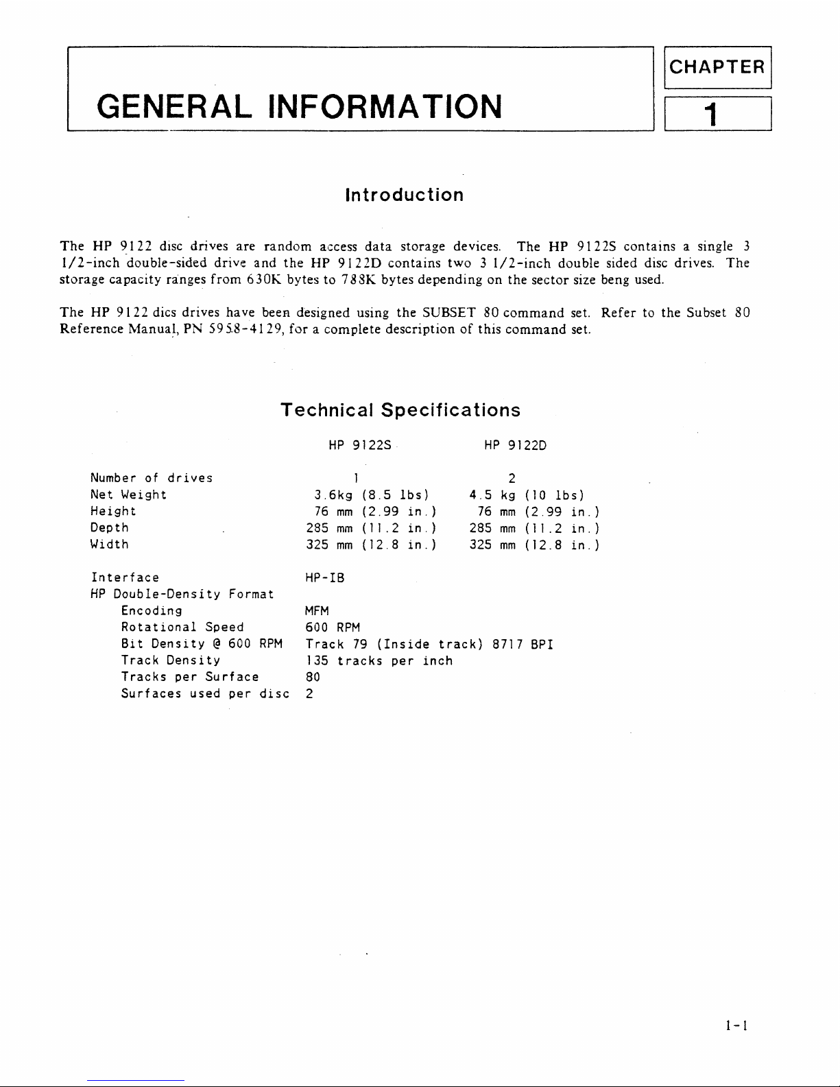
Introduction
The
HP
9122
disc
drives
are
random
access
data
storage
devices.
The
HP
9122S
contains
a single 3
1/2-inch
-double-sided
drive
and
the
HP
9122D
contains
two 3 I/2-inch
double sided disc drives.
The
storage
capacity
ranges
from
630K
bytes
to
7 8SK
bytes
depending
on
the
sector
size beng used.
The
HP
9122
dics drives
have
beeR designed using
the
SUBSET
80
command
set.
Refer
to
the
Subset
80
Reference
Manua~,
PN
595.8-4129,
for a complete
description
of
this
command
set.
Technical
Specifications
Number
of
drives
Net Weight
Height
Depth
Width
Interface
HP
Double-Density
Format
Encoding
Rotational
Speed
Bit
Density
@ 600
RPM
Track
Density
Tracks
per
Surface
Surfaces
used
per
disc
HP
9122S
HP
9122D
1
2
3.6kg
(8.5
lbs)
76
mm
(2.99
in.)
285
mm
(1
1 . 2
in.)
325
mm
(12.8
in.)
4.5
kg
(10
lbs)
76
mm
(2.99
285
mm
(
11
.2
325
mm
(12.8
HP-IB
MFM
600
RPM
Track
79
(Inside
track)
8717
BPI
135
tracks
per
inch
80
2
in.
)
in.
)
in.
)
1-
1

GENERAL
I!'FOR~IATION
1-2
Double-sided
Single-sided
Capacity
Bytes/Sector
256 512
1024
Sectors/Track
16
9
5
Tracks
80 80
80
Data Tr,acks
~\vailable
(----
154
------>
Access
Time
Track-to-Track
Seek
Maximum
Track-to-Track
See k (8 a t r a c k
~i
)
Average
Track-to-Track
Maximum
Rotational
Latency
Average
Rotational
Latency
Spindle
Motor
on
time
Maximum
Data
Access
Time
(Seek
plus
Latency
plus
Motor
on
time)
Average Data
Access
Time
15
ms/tri!:ck,
1242
ms
447
ms
100
ms
50
ms
400
ms
1.742
s
497
ms
NOTE
256
16
70
66
plus
42
ms
settling
The
HP
9122
disc
drives
spare
four
complete
tracks
and
reserve
two
tracks
for
system
use
with
double
sided
formats,
and
spare
four
tracks
in single sided
format.
Power
Requirements
86-125
volts
or
195-250
volts
@ 67
watts
RMS
(94
voltamps)
50-60
Hertz
Fuse lA, 250
for
115V
setting
.5A, 250
for
230V
setting
Operating
Limits
Temperature
HumiditY'
Altitude'
Non-operating
Limits
(Storage
and
Transit)
Temperature
Altitude
Environmental
Specs
10
to
40°C
(50
to
104°F)
20
to
80r.
with
maximum
wet
bulb
temperature
(non-condensing)
not
toe
x c e e d 29 ° C (850 F)
.
o
to
4572 m
(0
to
15,000
tt)
-40
to
60°C
(-40
to
140°F)
-304
to
15240 m
(-1000
to
50,000
tt)
GE~ERAL
I~FOR~fATION
NOTE
The
flexible disc in
the
HP
9122
disc drives
is
designed
for
operation
in
a
typical
office
environment.
Use
of
the
equipment
in
an
environment
containing
dirt,
dust,
or
cor-
rosive substances will cause
the
flexible disc
drives
and
medium
life
to
be
drastically
reduced.
Equipment
Supplied
The
following
equipment
is
supplied
with
each
HP
9122
disc drive.
Description
AC
Power Cord
Operator's
Manual
Disc
Shipping
Disc
Quantity
HP
Part
Number
Dependent
on
location
09122-90020
N/A
1150-1786
A
package
of
ten
discs,
product
number
92192A,
is
available
from
DMK.
Unpacking
The
HP 91
220/S
Disc
Drive
The
disc
drive
was
carefully
inspected
before
shipment.
Remove
the
unit
from
the
shipping
carton
and
carefully
inspect
the
unit
for
any
physical
damage
that
may
have
occurred
during
shipment.
If
you
find
any
damage, you
should
immediately
notify
the
dealer
and
file a
claim
with
any
carriers
involved.
[CAUTION
I
The
disc
drive
is
a precision
instrument.
Mechanical
shock
can
misalign
the
read/write
head,
resulting
in
read
errors
and/or
damaged
discs
whether
the
disc
is
operating
or
not.
When
moving
the
disc
unit,
care
must
be
taken
to
prevent
ex-:
cessive shock.
Install
the
shipping
disc
(P
/N
1150-1786
for
half
height
drives
and
1150-1787
for
full
height
drives)
before
moving
it
to
another
location.
If
you
do
not
have
the
parts
metioned,
they
may
be
purchased
from
Hewlett
Packard.'
1-3
GE",ERAL
I\:FOR\1A
TIO~
Cleaning
the
Case
The
disc
drive
case
is
made
from a white
plastic
material
and
is
not
painted.
The
rear
panel
has a durable,
non-toxic
label. In
the
event
of
damage
to
the
case
finish,
consult
your
HP
Sales
Office
for
touchup
paints.
I
CAUTION
I
Chemical
spray-·on
cleaners
used
for
appbances
and
other
household
and
industrial
applications
may
damage
the
case
finish.
Do
not
use
detergents
that
contain
ammonia,
benzenes,.
chlorides,
or
abrasives.
Before
cleaning
the
case,
disconnect
the
power
cord
and
HP-IB
cables.
Make
sure
that
any
disc
is
removed
from
the
drives.
Dampen a clean,
soft,
lint
-free
cloth
in a solution
of
clean
water
and
mild
soap. \Vipe
the
soiled
areas
of
the
case,
making
sure
that
no
cleaning
solution
gets
inside
the
case.
For
cleaning
more
hea
vi-
ly soiled areas, a
solution
of
80%
clean
water
and
20%
isopropyl
alcohol
may
be used.
Dry
the
areas
that
had
cleaning
solution
applied
with
a.nother
clean,
soft,
lint-free
cloth. A non-abrasive
eraser
may
be used
to
remove
pen
and
pencil
marks.
1-4
ICHAPTER
I
Installa tion
121
Configuring
Power
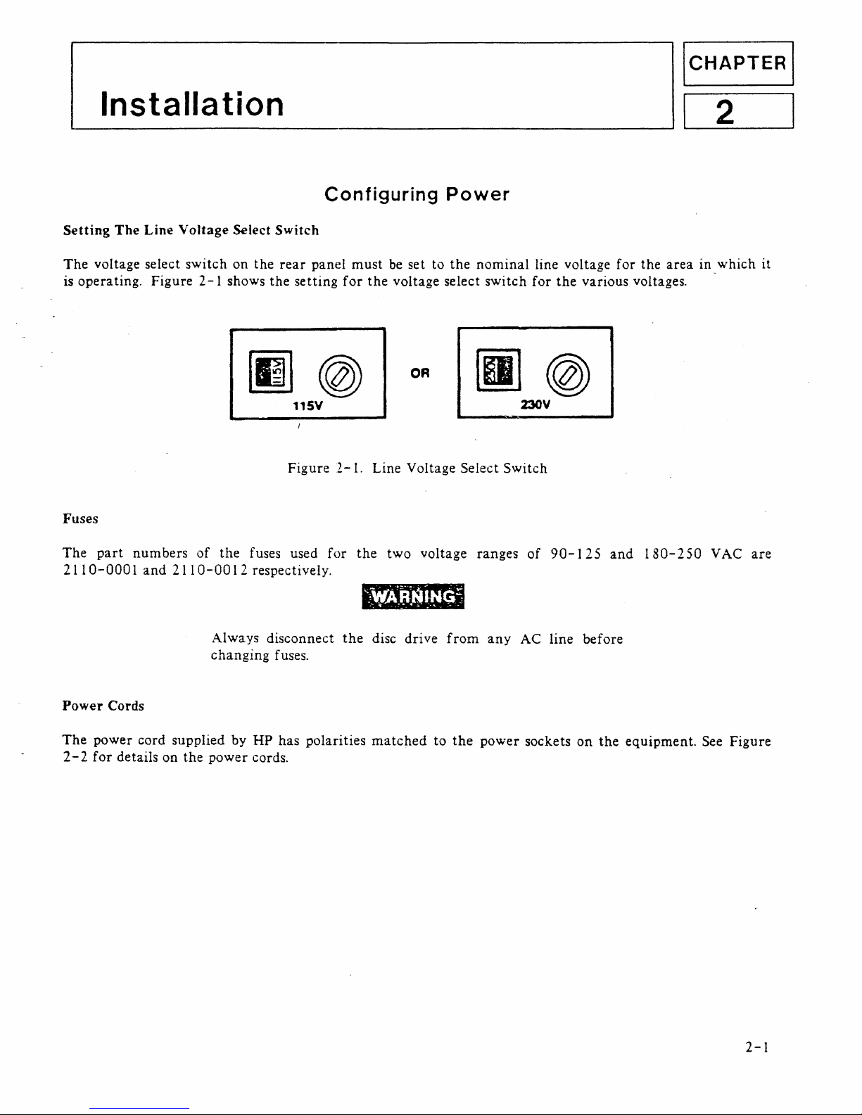
Setting
The
Line
Voltage
Select
Switch
The
voltage select switch on the
rear
panel must
be
set to
the
nominal line voltage for the
area
in _which it
is operating. Figure
2-1
shows
the
setting
for
the
voltage select switch
for
the
various voltages.
[g]@
OR
11SV
Figure
2-1.
Line Voltage Select Switch
Fuses
The
part
numbers of the fuses used for
the
two voltage ranges
of
90-125
and
180-250
VAC
are
2110-0001
and
2110-0012
respectively.
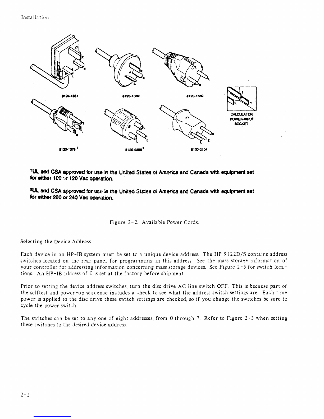
Power
Cords
'~.A~f(~~~5
.
-'
..
Always disconnect
the
disc drive
from
any
AC line before
changing fuses.
The
power cord supplied by HP has polarities
matched
to
the
power sockets on
the
equipment. See Figure
2-
2
for
details on the power cords.
2-1
InstallathJn
lUI..
tor
either
2Ul
tor
eithit'
Selecting
Each
device
switches
your
controller
tions.
Prior
the
power
cycle
The
these
An
to
seIftest
is
the
switches
switches
and
<:SA!1fJPf'OY9d
100
:')t
120
and
CSA
ar-proved
2GO
or
240
the
Devic~!
in
located
HP-IB
setting
and
applied
power
can
an
HP-IB
on
the
for
aJdressing
address
the
device
power-up
to
the
switch.
be
to
the
Addn~ss
set
desired
for
U84t
Vac
~Ition.
for
USE'
Vac,
ooenltion.
system
rear
panel
inf'Jrma
of 0 is
disc
to
set
address
sequen,;e
drive
anyone
device
in
the
United
in
the
Ur4ted
Figu.re 2 -
must
be
set
for
programming
tiCin
concerning
at
the
factory
switches,
includes a check
these
of
address.
switch
eight
turn
addresses,
States
States
2. A vaila
to a unique
settings
ot
of
in
mass
before
the
disc
to
are
from 0 through
Am&rica
America
bIe
Power
device
this
address. 5ee
storage
shipment.
drive
see
what
checked,
and
Canada
and
Canada
Cords.
address.
devices. See
AC
line
the
address
so
if
The
switch
you
7.
Refer
Wh
with
HP
the
OFF.
switch
change
equipment
equipment
91220/5
mass
storage
Figure
This
settings
the
to
Figure 2-3
set
set
contains
information
2 - 5
for
is
because
are.
switches
switch
Each
be
when
address
of
loca-
part
of
time
sure
to
setting
2-2
Installa tion
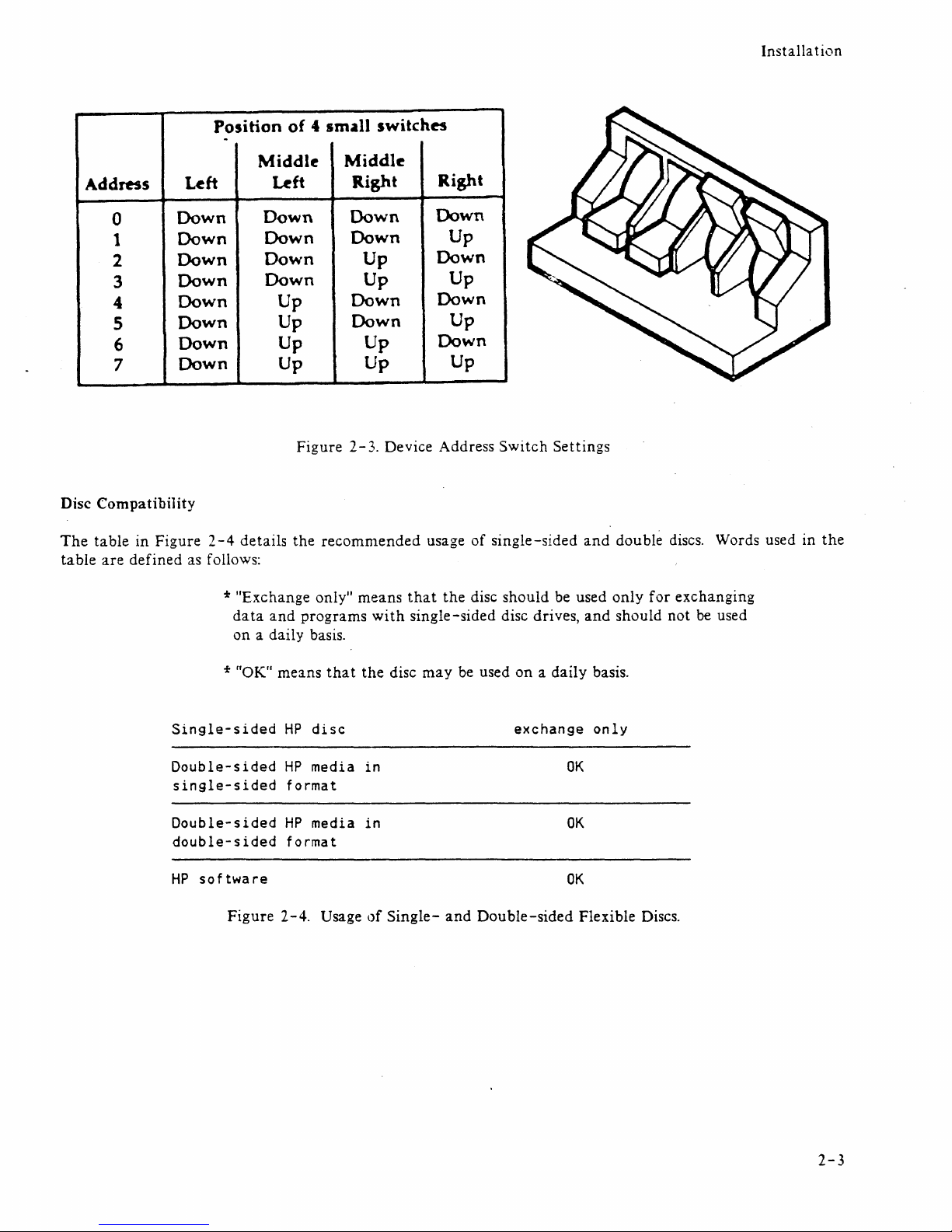
Address
0
1
2
3
4
5
6
7
Disc
Compatibility
The
table in Figure 2
table
are
defined as follows:
Position
Left
Down
Down
Down
Down
Down
Down
Down
Down
-4
of
4 small switches
-
Middle
Left
Down
Down
Down
Down
Up
Up
Up Up
Up
Figure
details the recommended usage of single-sided
Middle
Right
Down
Down
Up
Up
Down
Down
Right
Down
Up
Down
Up
Down
Up
Down
Up
2-3.
Device Address Switch Settings
Up
and
double discs. Words used in
the
* "Exchange only" means
data
on a daily basis.
* "OK
Single-sided
Double-sided
single-sided
Double-sided
double-sided
software
HP
Figure
and
II
means
HP
HP
format
HP
format
2-4.
programs
that
disc
media
media
Usage
with
the
in
in
of
that
the
disc should be used only
single-sided disc drives,
disc
may
Single-
be used
and
on
exchange
Double-sided
and
should not
a daily basis.
only
OK
OK
OK
Flexible Discs.
for
exchanging
be
used
2-3
Insta
lla t
ion
-..a-.rTT
AC
--1CeI
Power
==
-
9122
SWit-Ch--7
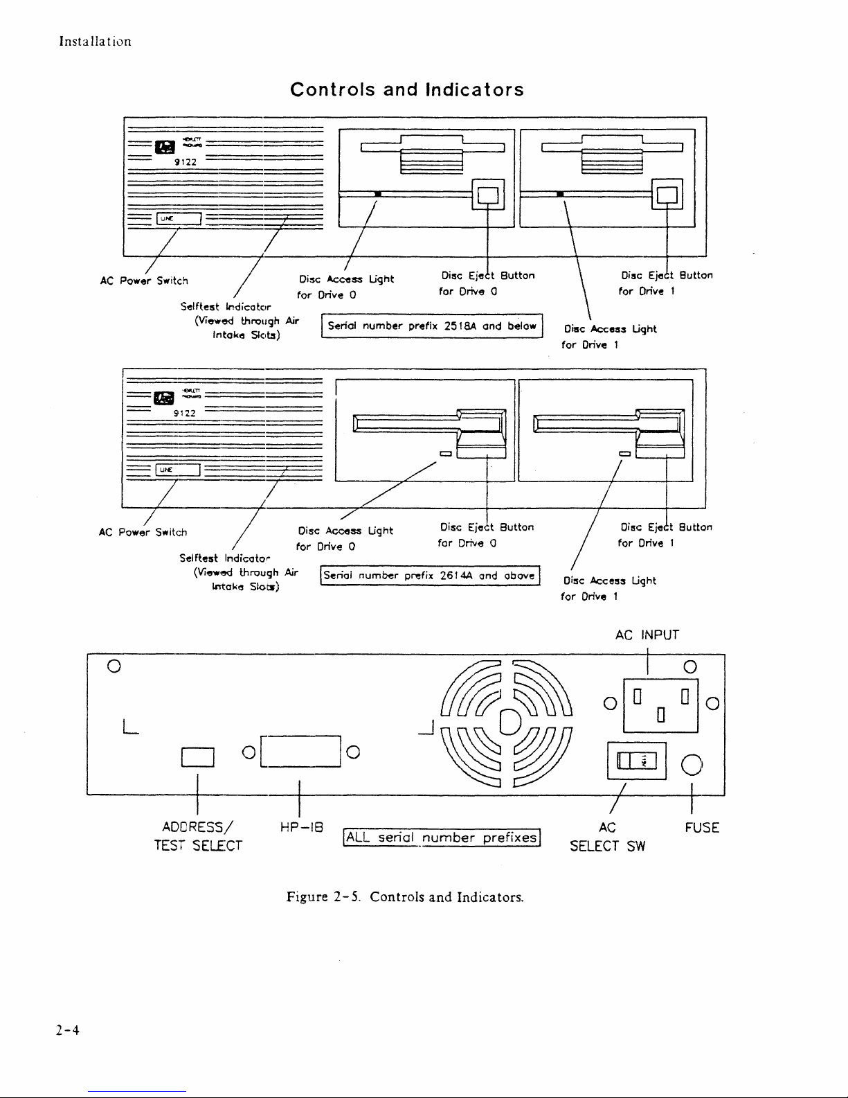
SelHest Indicate,r
(Viewed through
I!i
= :====
9122
Irttake
=E:=J=~
7
AC
POW?SWitCh 7
Self
test
Indicato
(View·ed
Lntake
Slel~)
---
/
r"
through
Slots)
Controls
Disc Access Light
for
Drive 0
Air
I . I
Seriol
. .
and
number
Indicators
Disc Eje t
for
Drive 0
prefix
2518A
I
Il
V
i
2
r=:ll
,/
/
/'
Disc Access Light
for
Drive 0
Air
ISenol
num~r
Disc
for
Drive 0
p~fix
2614A
Eje<
Button
and
below Disc
It
II
t
Button
and above I
for
Drive 1
/
Disc
for
Drive 1
Ac<::es3
/
If
for
Ac<::ess
Disc Eje t
for
Drive 1
Un,
ht
':I
V
t::ll
Disc
Ejec
Drive 1
Ught
Button
II
\
t
Butto
n
AC
INPUT
o
~~
~~
10
O~o
L
--1~~O@fl
LU
O
o O[_,.:J
~
~
I
[IJ]]
0
~-'+'----~-------------l~!-i
HP-IB
Figure 2-5.
IALL
serial
Controls
number
and
Indicators.
prefixes
I
AC
SELECT
FUSE
SW
2-4
ADDRESS/
TEST
SELECT
Installa tion
~ledia
~lonitor
Through a feature
called
Tvfedia
l\fonitor,
the
disc drive
automatically
monitors
the
cumulative
use
of
each
individual
disc. When
the
usage
of
a disc
is
approaching
a level
at
which
there
is
a risk
of
loss
of
data
through
normal disc wear, the disc access
light
on
the
front
panel
blinks
and
a clicking sound
is
heard.
Commands
will still
be
performed
by
the
computer.
However,
after a command
has been performed, the disc
drive
immediately resumes
the
warning
indication.
When
the
Media
Monitor
warning
occurs,
immediately
copy
your
disc. If you
continue
to use this disc,
the
disc drive will
eventually
automatically
write
protect
the
disc.
After
that
time, you will only be able to
read
data
from
the
disc
or
copy
the
disc.
Power-on
Self test
A
power-on
selftest
is
performed
automatically
when
you
turn
on
the
disc drive. The selftest first checks
the
HP-IB, FDC, RAM,
and
ROM, followed by a
WRITE/READ
test (if
an
initialized, non
write-protected
disc
is
inserted).
When
a WRITE test
is
'performed,
it
is
done
on
a reserved
area
of
the disc and no user
data
is
at
risk. The Selftest
LED
acts as a
pass/fail
indicator
and
is
visible
through
the
air
intake
slots.
When
an
initialized,
unprotected
disc
is
inserted; read, write,
and
motor-speed
tests are performed. A
write-
protected
disc will
not
allow
the
read
and
write
tests to run.
If
the
disc access
light
stays on
after
the
nor-
mal
testing time,
an
error
within
the
disc drive has been detected.
If
an
error
occurs,
refer
to
Chapter 4 for
troubleshooting procedures.
Write
Protect
Error
on
Initialization
A
motor
speed check
is
performed
before
initialization
is
performed.
If
the
motor
speed
is
on
either
side
of
the
tolerance
allowed, a
Write
Protect
Error
is
generated
and
the
disc
cannot
be initialized.
At
this point,
insert
another
disc.
If a write
protect
error
is
generated
again,
refer
to
Chapter
4 for troubleshooting
procedures.
If
no
write
protect
error
occurs
with
the
second disc,
then
the
first
disc used
is
bad
and
should
be discarded.
2-5

ICHAPTER
I
Interface
Information
I 3 I
HP
-18
Interface
Installation
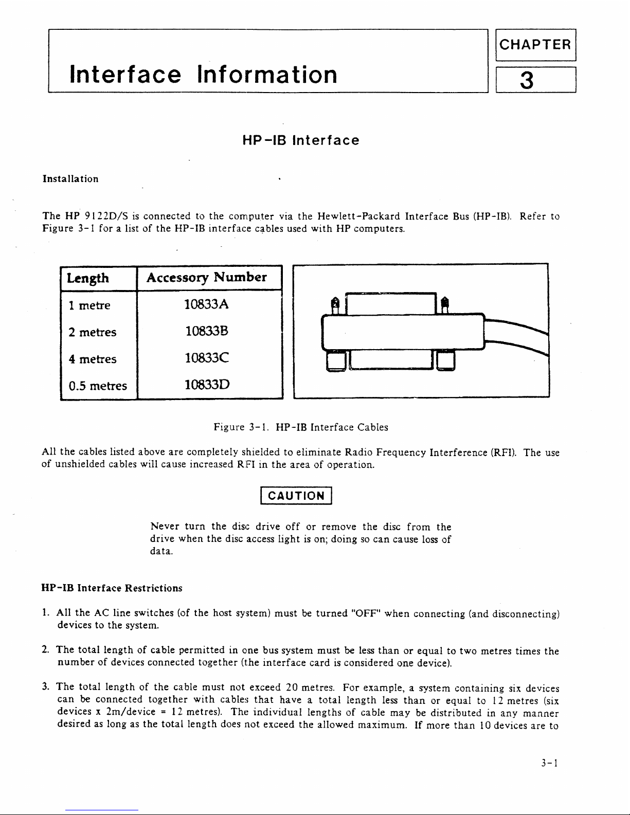
The
HP
91220/5
is
connected
to
the
computer
via
the
Hewlett-Packard
Interface
Bus (HP-IB).
Refer
to
Figure
3-1
for
a list
of
the
HP-IB
interface
c~bles
used
with
HP
computers.
Length
Accessory
Number
1 metre
1
0833
A
2 metres
10833B
4 metres
10833C
0.5 metres
10833D
Figure
3-1.
HP-IB
Interface
Cables
All
the
cables listed above
are
completely
shielded
to
eliminate
Radio
Frequency
Interference
(RFI).
The
use
of
unshielded
cables will cause
increased
RFI
in
the
area
of
operation.
I
CAUTION
I
Never
turn
the
disc
drive
off
or
remove
the
disc
from
the
drive
when
the
disc access
light
is
on;
doing
so
can
cause loss
of
data.
HP-IB
Interface
Restrictions
1.
All
the
AC
line
switches
(of
the
host system)
must
be
turned
"OFF"
when
connecting
(and disconnecting)
devices
to
the
system.
2.
The
total
length
of
cable
permitted
in
one
bus
system
must
be less
than
or
equal
to
two
metres
times
the
number
of
devices
connected
together
(the
interface
card
is
considered
one
device).
3.
The
total
length
of
the
cable
must
not
exceed
20
metres.
For
example, a system
containing
six devices
can
be
connected
together
with
cables
that
have a total
length
less
than
or
equal
to 12
metres
(six
devices x
2m/device
= 12 metres).
The
individual
lengths
of
cable
may
be
distributed
in
any
manner
desired
as long as
the
total
length
does
not
exceed
the
allowed
maximum.
If
more
than
10 devices
are
to
3-1

Interface
Information
be
connected
together,
cables
shorter
than
two
metres
must
be used
between
some
of
the
devices
to
keep
the
total
cable
length
less
than
20
metres.
4.
The
max:imum
number
of
devices
that
can
be
connected
together
in a
one-bus
system
is
15.
There
are
no
restrictions
to
the
way
cables
may
be
connected
together;
however,
it
is
recommended
that
no
more
than
four
piggyback
conneGtors be
stacked
together
on
one
device.
The
resulting
structure
could
exert
enough
force
on
thf~
connector
mounting
to
damage
it.
3-2
ICHAPTERi
~T_r_o_ub_l_e_s_ho_o_t_in
__
g
____________
~1
4 I
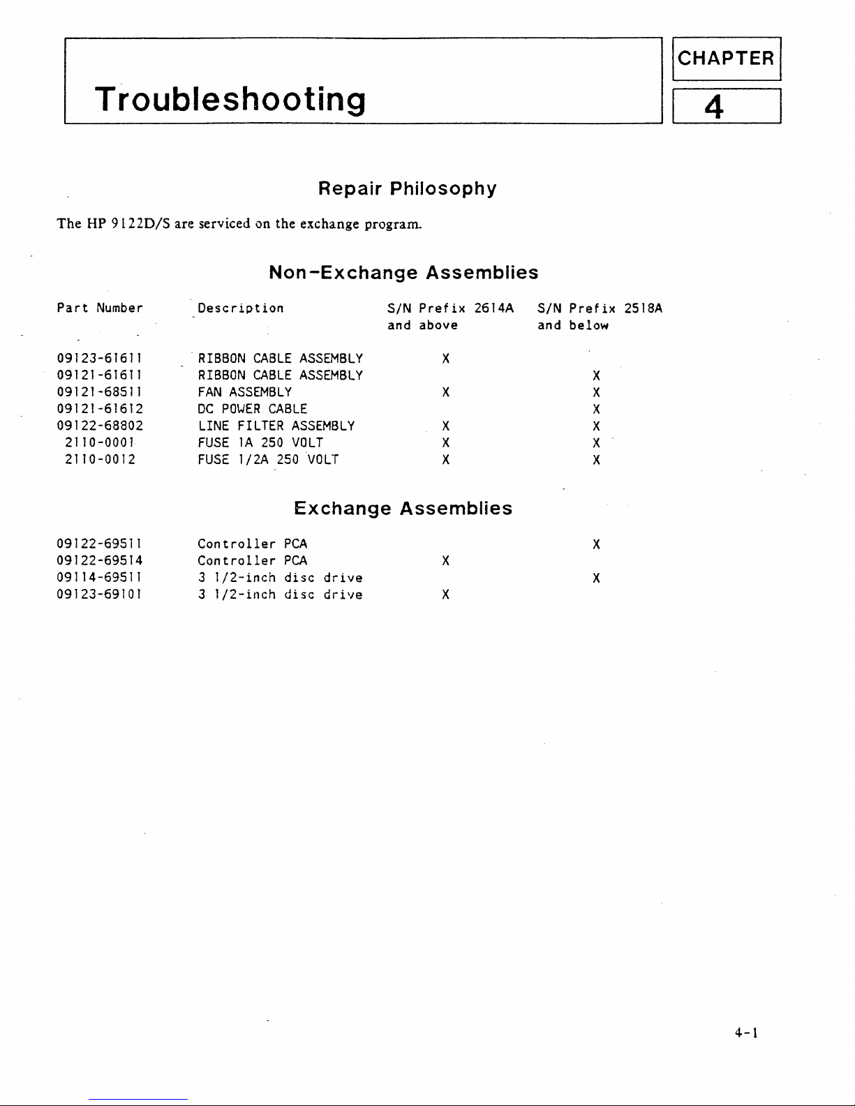
Repair
Philosophy
The
HP 9
12
20/S
are serviced on the exchange program.
Part
Number
09123-61611
09121-61611
09121-68511
09121-61612
09122-68802
2110-0001
2110-0012
09122-69511
09122-69514
09114-69511
09123-69101
Non-Exchange
Assemblies
Description
SIN
Prefix
2614A
and
above
-
RIBBON
CABLE
ASSEMBLY
X
RIBBON
CABLE
ASSEMBLY
FAN
ASSEMBLY
X
DC
POWER
CABLE
LINE
FILTER
ASSEMBLY
X
FUSE
1A
250
VOLT
X
FUSE
1/2A
250
'VOLT
X
Exchange
Assemblies
Controller
PCA
Controller
PCA
X
3
1/2-inch
disc
drive
3
1/2-inch
disc
drive
X
SIN
Prefix
2518A
and below
X
X
X
X
X
X
X
X
4-1
 Loading...