

Page 1
HP LaserJet 9000/9040/9050
Service Manual
Page 2

Page 3

HP LaserJet 9000, 9040, and 9050 Series printers
Service _____________________
Page 4

Copyright and License
© 2005 Copyright Hewlett-Packard
Development Company, LP
Reproduction, adaptation or translation
without prior written permission is prohibited,
except as allowed under the copyright laws.
Part number: Q3721-90963
Edition 1, 4/2005
The information contained herein is subject to
change without notice.
The only warranties for HP products and
services are set forth in the express warranty
statements accompanying such products and
services. Nothing herein should be construed
as constituting an additional warranty. HP
shall not be liable for technical or editorial
errors or omissions contained herein.
Trademark Credits
®
Adobe
and PostScript® are trademarks of
Adobe Systems Incorporated.
MS-DOS
®
is a U.S. registered trademark of
Microsoft Corporation.
E
NERGY STAR
®
is a U.S. registered service
mark of the United States Environmental
Protection Agency.
Page 5

Table of contents
Table of contents
List of tables
List of figures
1 Product information
Product features of the HP LaserJet 9000 Series printers . . . . . . . . . . . . . . . . . .2
Product features of the HP LaserJet 9040/9050 Series printers. . . . . . . . . . . . . . 4
Product specifications . . . . . . . . . . . . . . . . . . . . . . . . . . . . . . . . . . . . . . . . . . . . . .6
Product overview. . . . . . . . . . . . . . . . . . . . . . . . . . . . . . . . . . . . . . . . . . . . . . . . .10
External view of the printer and accessories . . . . . . . . . . . . . . . . . . . . . . . . 10
Interface connections . . . . . . . . . . . . . . . . . . . . . . . . . . . . . . . . . . . . . . . . . . 11
Optional accessories. . . . . . . . . . . . . . . . . . . . . . . . . . . . . . . . . . . . . . . . . . . 12
Regulatory information . . . . . . . . . . . . . . . . . . . . . . . . . . . . . . . . . . . . . . . . . . . .13
Regulatory requirements. . . . . . . . . . . . . . . . . . . . . . . . . . . . . . . . . . . . . . . . 13
FCC regulations . . . . . . . . . . . . . . . . . . . . . . . . . . . . . . . . . . . . . . . . . . . . . .13
Declaration of conformity . . . . . . . . . . . . . . . . . . . . . . . . . . . . . . . . . . . . . . . 13
Environmental product stewardship program . . . . . . . . . . . . . . . . . . . . . . . .13
Service approach . . . . . . . . . . . . . . . . . . . . . . . . . . . . . . . . . . . . . . . . . . . . . . . . 14
Parts and supplies . . . . . . . . . . . . . . . . . . . . . . . . . . . . . . . . . . . . . . . . . . . .14
Warranty . . . . . . . . . . . . . . . . . . . . . . . . . . . . . . . . . . . . . . . . . . . . . . . . . . . .14
Limited warranty for print-cartridge life . . . . . . . . . . . . . . . . . . . . . . . . . . 14
2 Product requirements
Site requirements . . . . . . . . . . . . . . . . . . . . . . . . . . . . . . . . . . . . . . . . . . . . . . . . 16
Operating environment . . . . . . . . . . . . . . . . . . . . . . . . . . . . . . . . . . . . . . . .16
Space requirements . . . . . . . . . . . . . . . . . . . . . . . . . . . . . . . . . . . . . . . . . . . 17
Media specifications . . . . . . . . . . . . . . . . . . . . . . . . . . . . . . . . . . . . . . . . . . . . . . 19
Guidelines for selecting print media . . . . . . . . . . . . . . . . . . . . . . . . . . . . . . .19
Special media specifications. . . . . . . . . . . . . . . . . . . . . . . . . . . . . . . . . . . . .19
Storing print media . . . . . . . . . . . . . . . . . . . . . . . . . . . . . . . . . . . . . . . . . . 22
Media input/output options . . . . . . . . . . . . . . . . . . . . . . . . . . . . . . . . . . . . . . . . . 25
Trays, bins, and paper handling . . . . . . . . . . . . . . . . . . . . . . . . . . . . . . . . . . 25
Supported sizes of paper for input and output . . . . . . . . . . . . . . . . . . . . . . .26
3 Product configuration
Using the control panel . . . . . . . . . . . . . . . . . . . . . . . . . . . . . . . . . . . . . . . . . . . 30
Control-panel buttons . . . . . . . . . . . . . . . . . . . . . . . . . . . . . . . . . . . . . . . . . . 31
Numeric keypad commands . . . . . . . . . . . . . . . . . . . . . . . . . . . . . . . . . . . . 32
Settings and defaults. . . . . . . . . . . . . . . . . . . . . . . . . . . . . . . . . . . . . . . . . . . . . .33
Setting the display language. . . . . . . . . . . . . . . . . . . . . . . . . . . . . . . . . . . . . 33
Setting the tray registration . . . . . . . . . . . . . . . . . . . . . . . . . . . . . . . . . . . . . 33
Printer driver information. . . . . . . . . . . . . . . . . . . . . . . . . . . . . . . . . . . . . . . .36
Control-panel menus. . . . . . . . . . . . . . . . . . . . . . . . . . . . . . . . . . . . . . . . . . . . . . 37
Using a menu map . . . . . . . . . . . . . . . . . . . . . . . . . . . . . . . . . . . . . . . . . . . . 37
iii
Page 6

Retrieve job menu . . . . . . . . . . . . . . . . . . . . . . . . . . . . . . . . . . . . . . . . . . . . . . . 38
Information menu . . . . . . . . . . . . . . . . . . . . . . . . . . . . . . . . . . . . . . . . . . . . . . . . 38
Paper-handling menu . . . . . . . . . . . . . . . . . . . . . . . . . . . . . . . . . . . . . . . . . . . . . 39
Configure device menu. . . . . . . . . . . . . . . . . . . . . . . . . . . . . . . . . . . . . . . . . . . . 41
Printing submenu . . . . . . . . . . . . . . . . . . . . . . . . . . . . . . . . . . . . . . . . . . . . . 41
Print-quality submenu . . . . . . . . . . . . . . . . . . . . . . . . . . . . . . . . . . . . . . . . . 44
System setup submenu . . . . . . . . . . . . . . . . . . . . . . . . . . . . . . . . . . . . . . . . 46
I/O submenu. . . . . . . . . . . . . . . . . . . . . . . . . . . . . . . . . . . . . . . . . . . . . . . . . 48
Resets submenu . . . . . . . . . . . . . . . . . . . . . . . . . . . . . . . . . . . . . . . . . . . . . 53
Diagnostics menu. . . . . . . . . . . . . . . . . . . . . . . . . . . . . . . . . . . . . . . . . . . . . . . . 54
Service menu . . . . . . . . . . . . . . . . . . . . . . . . . . . . . . . . . . . . . . . . . . . . . . . . . . . 54
Remote firmware upgrade (RFU) . . . . . . . . . . . . . . . . . . . . . . . . . . . . . . . . . . . 55
Upgrading firmware to a single printer. . . . . . . . . . . . . . . . . . . . . . . . . . . . . 55
4 Product maintenance
Preventative maintenance . . . . . . . . . . . . . . . . . . . . . . . . . . . . . . . . . . . . . . . . . 60
Preventive maintenance kit contents . . . . . . . . . . . . . . . . . . . . . . . . . . . . . . 60
Cleaning the printer and accessories . . . . . . . . . . . . . . . . . . . . . . . . . . . . . . . . . 61
General cleaning . . . . . . . . . . . . . . . . . . . . . . . . . . . . . . . . . . . . . . . . . . . . . 61
Internal cleaning. . . . . . . . . . . . . . . . . . . . . . . . . . . . . . . . . . . . . . . . . . . . . . 62
Fuser cleaning . . . . . . . . . . . . . . . . . . . . . . . . . . . . . . . . . . . . . . . . . . . . . . . 65
Print cartridge information . . . . . . . . . . . . . . . . . . . . . . . . . . . . . . . . . . . . . . . . . 67
Storage. . . . . . . . . . . . . . . . . . . . . . . . . . . . . . . . . . . . . . . . . . . . . . . . . . . . . 67
Handling instructions . . . . . . . . . . . . . . . . . . . . . . . . . . . . . . . . . . . . . . . . . . 67
Refilled print cartridges . . . . . . . . . . . . . . . . . . . . . . . . . . . . . . . . . . . . . . . . 68
Print-cartridge weights . . . . . . . . . . . . . . . . . . . . . . . . . . . . . . . . . . . . . . . . . 68
Print-cartridge life expectancy . . . . . . . . . . . . . . . . . . . . . . . . . . . . . . . . . . . 68
Saving toner by using EconoMode . . . . . . . . . . . . . . . . . . . . . . . . . . . . . . . 68
5 Theory of operation
Basic operation. . . . . . . . . . . . . . . . . . . . . . . . . . . . . . . . . . . . . . . . . . . . . . . . . . 70
Sequence of operation. . . . . . . . . . . . . . . . . . . . . . . . . . . . . . . . . . . . . . . . . 71
Power-on sequence . . . . . . . . . . . . . . . . . . . . . . . . . . . . . . . . . . . . . . . . . . 73
Timing chart . . . . . . . . . . . . . . . . . . . . . . . . . . . . . . . . . . . . . . . . . . . . . . . . . 74
Engine control system . . . . . . . . . . . . . . . . . . . . . . . . . . . . . . . . . . . . . . . . . . . . 75
DC controller PCA . . . . . . . . . . . . . . . . . . . . . . . . . . . . . . . . . . . . . . . . . . . . 76
DC controller operations . . . . . . . . . . . . . . . . . . . . . . . . . . . . . . . . . . . . . . . 77
High-voltage power supply circuit . . . . . . . . . . . . . . . . . . . . . . . . . . . . . . . . 78
Low-voltage power supply unit. . . . . . . . . . . . . . . . . . . . . . . . . . . . . . . . . . . 80
Formatter system . . . . . . . . . . . . . . . . . . . . . . . . . . . . . . . . . . . . . . . . . . . . . . . . 81
Formatter hardware . . . . . . . . . . . . . . . . . . . . . . . . . . . . . . . . . . . . . . . . . . . 81
Laser/scanner system . . . . . . . . . . . . . . . . . . . . . . . . . . . . . . . . . . . . . . . . . . . . 83
Image formation system . . . . . . . . . . . . . . . . . . . . . . . . . . . . . . . . . . . . . . . . . . 84
The eight processes of image formation . . . . . . . . . . . . . . . . . . . . . . . . . . . 84
Print cartridge. . . . . . . . . . . . . . . . . . . . . . . . . . . . . . . . . . . . . . . . . . . . . . . . 85
Pickup and feed system . . . . . . . . . . . . . . . . . . . . . . . . . . . . . . . . . . . . . . . . . . . 87
Media-size detection . . . . . . . . . . . . . . . . . . . . . . . . . . . . . . . . . . . . . . . . . . 87
Media-level detection . . . . . . . . . . . . . . . . . . . . . . . . . . . . . . . . . . . . . . . . . . 87
Multifeed prevention. . . . . . . . . . . . . . . . . . . . . . . . . . . . . . . . . . . . . . . . . . . 87
Overhead-transparency detection . . . . . . . . . . . . . . . . . . . . . . . . . . . . . . . . 87
Fuser-wrapping-jam detection . . . . . . . . . . . . . . . . . . . . . . . . . . . . . . . . . . . 87
Jam detection . . . . . . . . . . . . . . . . . . . . . . . . . . . . . . . . . . . . . . . . . . . . . . . 88
Tray 1 . . . . . . . . . . . . . . . . . . . . . . . . . . . . . . . . . . . . . . . . . . . . . . . . . . . . . . . . . 93
Tray 1 driver PCA. . . . . . . . . . . . . . . . . . . . . . . . . . . . . . . . . . . . . . . . . . . . . 93
Power supply . . . . . . . . . . . . . . . . . . . . . . . . . . . . . . . . . . . . . . . . . . . . . . . . 93
Sequence of operation. . . . . . . . . . . . . . . . . . . . . . . . . . . . . . . . . . . . . . . . . 93
Pickup and feed . . . . . . . . . . . . . . . . . . . . . . . . . . . . . . . . . . . . . . . . . . . . . . 94
Jam detection . . . . . . . . . . . . . . . . . . . . . . . . . . . . . . . . . . . . . . . . . . . . . . . 94
iv Table of contents
Page 7

Tray 4 . . . . . . . . . . . . . . . . . . . . . . . . . . . . . . . . . . . . . . . . . . . . . . . . . . . . . . . . . 95
Tray 4 driver PCA . . . . . . . . . . . . . . . . . . . . . . . . . . . . . . . . . . . . . . . . . . . . .95
Power supply . . . . . . . . . . . . . . . . . . . . . . . . . . . . . . . . . . . . . . . . . . . . . . . .95
Sequence of operation . . . . . . . . . . . . . . . . . . . . . . . . . . . . . . . . . . . . . . . . . 95
Pickup and feed . . . . . . . . . . . . . . . . . . . . . . . . . . . . . . . . . . . . . . . . . . . . . . 96
Media-level and media-size detection. . . . . . . . . . . . . . . . . . . . . . . . . . . . . . 96
Jam detection . . . . . . . . . . . . . . . . . . . . . . . . . . . . . . . . . . . . . . . . . . . . . . . . 96
6 Removal and replace ment
Introduction . . . . . . . . . . . . . . . . . . . . . . . . . . . . . . . . . . . . . . . . . . . . . . . . . . . . . 99
Removal and replacement strategy . . . . . . . . . . . . . . . . . . . . . . . . . . . . . . . 99
Repair notices. . . . . . . . . . . . . . . . . . . . . . . . . . . . . . . . . . . . . . . . . . . . . . . .99
Electrostatic discharge (ESD). . . . . . . . . . . . . . . . . . . . . . . . . . . . . . . . . . . . 99
Required tools. . . . . . . . . . . . . . . . . . . . . . . . . . . . . . . . . . . . . . . . . . . . . . . . 99
Orientation of the printer (with tray 4) . . . . . . . . . . . . . . . . . . . . . . . . . . . . . 100
Covers. . . . . . . . . . . . . . . . . . . . . . . . . . . . . . . . . . . . . . . . . . . . . . . . . . . . . . . . 101
Right top cover . . . . . . . . . . . . . . . . . . . . . . . . . . . . . . . . . . . . . . . . . . . . . . 101
Left top cover . . . . . . . . . . . . . . . . . . . . . . . . . . . . . . . . . . . . . . . . . . . . . . . 103
Front cover . . . . . . . . . . . . . . . . . . . . . . . . . . . . . . . . . . . . . . . . . . . . . . . . . 104
Right door . . . . . . . . . . . . . . . . . . . . . . . . . . . . . . . . . . . . . . . . . . . . . . . . . .105
Right lower cover . . . . . . . . . . . . . . . . . . . . . . . . . . . . . . . . . . . . . . . . . . . . 106
Left door and diverter . . . . . . . . . . . . . . . . . . . . . . . . . . . . . . . . . . . . . . . . . 107
Left back cover . . . . . . . . . . . . . . . . . . . . . . . . . . . . . . . . . . . . . . . . . . . . . . 108
Back cover . . . . . . . . . . . . . . . . . . . . . . . . . . . . . . . . . . . . . . . . . . . . . . . . . 109
Right and left rail covers . . . . . . . . . . . . . . . . . . . . . . . . . . . . . . . . . . . . . . . 110
Top assemblies . . . . . . . . . . . . . . . . . . . . . . . . . . . . . . . . . . . . . . . . . . . . . . . . . 111
Control panel. . . . . . . . . . . . . . . . . . . . . . . . . . . . . . . . . . . . . . . . . . . . . . . . 111
Laser/scanner assembly. . . . . . . . . . . . . . . . . . . . . . . . . . . . . . . . . . . . . . . 112
Delivery assembly . . . . . . . . . . . . . . . . . . . . . . . . . . . . . . . . . . . . . . . . . . . 113
Delivery-fan assembly. . . . . . . . . . . . . . . . . . . . . . . . . . . . . . . . . . . . . . . . . 114
Delivery-assembly fans and face-down-bin fan (fans 3, 6, and 4) . . . . . . . 115
Delivery motor. . . . . . . . . . . . . . . . . . . . . . . . . . . . . . . . . . . . . . . . . . . . . . . 116
Cartridge release lever . . . . . . . . . . . . . . . . . . . . . . . . . . . . . . . . . . . . . . . . 117
Front assemblies. . . . . . . . . . . . . . . . . . . . . . . . . . . . . . . . . . . . . . . . . . . . . . . . 119
Print cartridge . . . . . . . . . . . . . . . . . . . . . . . . . . . . . . . . . . . . . . . . . . . . . . . 119
Transfer-roller assembly . . . . . . . . . . . . . . . . . . . . . . . . . . . . . . . . . . . . . . . 120
Tray 2 and tray 3 (interchangeable) . . . . . . . . . . . . . . . . . . . . . . . . . . . . . . 121
Rollers (pickup, feed, or separation). . . . . . . . . . . . . . . . . . . . . . . . . . . . . . 122
Fuser-jam-removal knob. . . . . . . . . . . . . . . . . . . . . . . . . . . . . . . . . . . . . . .123
Registration-jam-removal knob. . . . . . . . . . . . . . . . . . . . . . . . . . . . . . . . . . 124
Right assemblies. . . . . . . . . . . . . . . . . . . . . . . . . . . . . . . . . . . . . . . . . . . . . . . . 125
Tray 1 . . . . . . . . . . . . . . . . . . . . . . . . . . . . . . . . . . . . . . . . . . . . . . . . . . . . . 125
Paper-input unit (PIU) . . . . . . . . . . . . . . . . . . . . . . . . . . . . . . . . . . . . . . . . . 126
Registration assembly. . . . . . . . . . . . . . . . . . . . . . . . . . . . . . . . . . . . . . . . . 129
Transfer-guide assembly . . . . . . . . . . . . . . . . . . . . . . . . . . . . . . . . . . . . . . 131
Left assemblies . . . . . . . . . . . . . . . . . . . . . . . . . . . . . . . . . . . . . . . . . . . . . . . . . 133
Duplexer . . . . . . . . . . . . . . . . . . . . . . . . . . . . . . . . . . . . . . . . . . . . . . . . . . . 133
Fuser assembly. . . . . . . . . . . . . . . . . . . . . . . . . . . . . . . . . . . . . . . . . . . . . . 134
Back assemblies . . . . . . . . . . . . . . . . . . . . . . . . . . . . . . . . . . . . . . . . . . . . . . . . 135
Formatter . . . . . . . . . . . . . . . . . . . . . . . . . . . . . . . . . . . . . . . . . . . . . . . . . .135
Low-voltage power supply . . . . . . . . . . . . . . . . . . . . . . . . . . . . . . . . . . . . .136
High-voltage power supply . . . . . . . . . . . . . . . . . . . . . . . . . . . . . . . . . . . . . 137
DC controller. . . . . . . . . . . . . . . . . . . . . . . . . . . . . . . . . . . . . . . . . . . . . . . .138
Toner-sensor contact assembly . . . . . . . . . . . . . . . . . . . . . . . . . . . . . . . . . 140
Drum motor. . . . . . . . . . . . . . . . . . . . . . . . . . . . . . . . . . . . . . . . . . . . . . . . .141
Feed-drive assembly . . . . . . . . . . . . . . . . . . . . . . . . . . . . . . . . . . . . . . . . . 142
Power-supply fan (fan 1). . . . . . . . . . . . . . . . . . . . . . . . . . . . . . . . . . . . . . . 143
Cartridge fan (fan 5) . . . . . . . . . . . . . . . . . . . . . . . . . . . . . . . . . . . . . . . . . . 144
v
Page 8

Controller fan (fan 2) . . . . . . . . . . . . . . . . . . . . . . . . . . . . . . . . . . . . . . . . . 145
Jetlink connector . . . . . . . . . . . . . . . . . . . . . . . . . . . . . . . . . . . . . . . . . . . . 146
Fuser-connector holder assembly . . . . . . . . . . . . . . . . . . . . . . . . . . . . . . . 147
Fuser delivery-drive assembly . . . . . . . . . . . . . . . . . . . . . . . . . . . . . . . . . . 149
Tray 4 . . . . . . . . . . . . . . . . . . . . . . . . . . . . . . . . . . . . . . . . . . . . . . . . . . . . . . . . 151
Orientation . . . . . . . . . . . . . . . . . . . . . . . . . . . . . . . . . . . . . . . . . . . . . . . . . 151
Left side cover . . . . . . . . . . . . . . . . . . . . . . . . . . . . . . . . . . . . . . . . . . . . . . 151
Right side cover . . . . . . . . . . . . . . . . . . . . . . . . . . . . . . . . . . . . . . . . . . . . 152
Back covers . . . . . . . . . . . . . . . . . . . . . . . . . . . . . . . . . . . . . . . . . . . . . . . . 153
Tray 4. . . . . . . . . . . . . . . . . . . . . . . . . . . . . . . . . . . . . . . . . . . . . . . . . . . . . 154
Rollers (pickup, feed, and separation) . . . . . . . . . . . . . . . . . . . . . . . . . . . 155
Registration assembly . . . . . . . . . . . . . . . . . . . . . . . . . . . . . . . . . . . . . . . . 156
Drive motor. . . . . . . . . . . . . . . . . . . . . . . . . . . . . . . . . . . . . . . . . . . . . . . . . 157
Drive assembly. . . . . . . . . . . . . . . . . . . . . . . . . . . . . . . . . . . . . . . . . . . . . . 158
Controller board . . . . . . . . . . . . . . . . . . . . . . . . . . . . . . . . . . . . . . . . . . . . . 159
Paper-size detection switch PCA . . . . . . . . . . . . . . . . . . . . . . . . . . . . . . . 160
Power supply . . . . . . . . . . . . . . . . . . . . . . . . . . . . . . . . . . . . . . . . . . . . . . . 161
Pickup assembly . . . . . . . . . . . . . . . . . . . . . . . . . . . . . . . . . . . . . . . . . . . . 162
Paper-connecting unit . . . . . . . . . . . . . . . . . . . . . . . . . . . . . . . . . . . . . . . . 163
7 Troubleshooting
Troubleshooting process . . . . . . . . . . . . . . . . . . . . . . . . . . . . . . . . . . . . . . . . . 167
Basic troubleshooting process flow . . . . . . . . . . . . . . . . . . . . . . . . . . . . . . 168
Preliminary operating checks . . . . . . . . . . . . . . . . . . . . . . . . . . . . . . . . . . 170
General troubleshooting information . . . . . . . . . . . . . . . . . . . . . . . . . . . . . . . . 171
Abnormal noises are evident, such as grinding or
chattering when the main motor is turned on. . . . . . . . . . . . . . . . . . . . . . . 171
Media does not feed from tray x when printing from a software
program; the paper-path test is successful . . . . . . . . . . . . . . . . . . . . . . . . 171
Media does not print from tray 4 . . . . . . . . . . . . . . . . . . . . . . . . . . . . . . . . 171
The printer stops printing and hangs on certain jobs. . . . . . . . . . . . . . . . . 171
Envelopes are wrinkling . . . . . . . . . . . . . . . . . . . . . . . . . . . . . . . . . . . . . . . 172
Fusing is poor. . . . . . . . . . . . . . . . . . . . . . . . . . . . . . . . . . . . . . . . . . . . . . . 172
The printer feeds from an incorrect tray when different media
is selected for the first page of the job . . . . . . . . . . . . . . . . . . . . . . . . . . . . 172
Power-on . . . . . . . . . . . . . . . . . . . . . . . . . . . . . . . . . . . . . . . . . . . . . . . . . . . . . 174
Troubleshooting by using control-panel messages . . . . . . . . . . . . . . . . . . . . . 175
Event log page . . . . . . . . . . . . . . . . . . . . . . . . . . . . . . . . . . . . . . . . . . . . . 175
Control-panel messages. . . . . . . . . . . . . . . . . . . . . . . . . . . . . . . . . . . . . . . . . . 178
Control-panel and event-log message format . . . . . . . . . . . . . . . . . . . . . . 179
Printer-message tables . . . . . . . . . . . . . . . . . . . . . . . . . . . . . . . . . . . . . . . 179
Alphabetical error messages . . . . . . . . . . . . . . . . . . . . . . . . . . . . . . . . . . . 180
Numerical error messages . . . . . . . . . . . . . . . . . . . . . . . . . . . . . . . . . . . . 188
User- and service-level diagnostics . . . . . . . . . . . . . . . . . . . . . . . . . . . . . . . . . 213
Paper-path test. . . . . . . . . . . . . . . . . . . . . . . . . . . . . . . . . . . . . . . . . . . . . . 213
Service test . . . . . . . . . . . . . . . . . . . . . . . . . . . . . . . . . . . . . . . . . . . . . . . . 213
Service-level diagnostics . . . . . . . . . . . . . . . . . . . . . . . . . . . . . . . . . . . . . . . . . 215
Engine test . . . . . . . . . . . . . . . . . . . . . . . . . . . . . . . . . . . . . . . . . . . . . . . . 215
Service menu . . . . . . . . . . . . . . . . . . . . . . . . . . . . . . . . . . . . . . . . . . . . . . . 215
Diagnostics flowchart . . . . . . . . . . . . . . . . . . . . . . . . . . . . . . . . . . . . . . . . . 216
Other diagnostics for the HP LaserJet 9000, 9000mfp, and 9000Lmfp . . . . . . 217
Cold reset. . . . . . . . . . . . . . . . . . . . . . . . . . . . . . . . . . . . . . . . . . . . . . . . . . 217
Other diagnostics for the HP LaserJet 9040/9050, 9040mfp, and 9050mfp. . . 219
Cold reset. . . . . . . . . . . . . . . . . . . . . . . . . . . . . . . . . . . . . . . . . . . . . . . . . . 219
Tray 4 diagnostics . . . . . . . . . . . . . . . . . . . . . . . . . . . . . . . . . . . . . . . . . . . . . . 221
Diagnostics label . . . . . . . . . . . . . . . . . . . . . . . . . . . . . . . . . . . . . . . . . . . . 221
Motor test. . . . . . . . . . . . . . . . . . . . . . . . . . . . . . . . . . . . . . . . . . . . . . . . . . 221
Standalone running test. . . . . . . . . . . . . . . . . . . . . . . . . . . . . . . . . . . . . . . 222
vi Table of contents
Page 9

Sensor test . . . . . . . . . . . . . . . . . . . . . . . . . . . . . . . . . . . . . . . . . . . . . . . . . 222
Light-pattern interpretation . . . . . . . . . . . . . . . . . . . . . . . . . . . . . . . . . . . . . 223
Jam troubleshooting . . . . . . . . . . . . . . . . . . . . . . . . . . . . . . . . . . . . . . . . . . . . . 224
Jams . . . . . . . . . . . . . . . . . . . . . . . . . . . . . . . . . . . . . . . . . . . . . . . . . . . . . . 225
Customer print job. . . . . . . . . . . . . . . . . . . . . . . . . . . . . . . . . . . . . . . . . . . . 225
Clearing jams . . . . . . . . . . . . . . . . . . . . . . . . . . . . . . . . . . . . . . . . . . . . . . .225
Evaluate the information pages. . . . . . . . . . . . . . . . . . . . . . . . . . . . . . . . . . . . . 226
Configuration page . . . . . . . . . . . . . . . . . . . . . . . . . . . . . . . . . . . . . . . . . .226
Jetdirect page . . . . . . . . . . . . . . . . . . . . . . . . . . . . . . . . . . . . . . . . . . . . . .229
Supplies status page . . . . . . . . . . . . . . . . . . . . . . . . . . . . . . . . . . . . . . . . . 230
Usage page . . . . . . . . . . . . . . . . . . . . . . . . . . . . . . . . . . . . . . . . . . . . . . . 231
File directory page . . . . . . . . . . . . . . . . . . . . . . . . . . . . . . . . . . . . . . . . . . .232
Image-formation troubleshooting . . . . . . . . . . . . . . . . . . . . . . . . . . . . . . . . . . . 233
Check the print cartridge. . . . . . . . . . . . . . . . . . . . . . . . . . . . . . . . . . . . . . . 234
EconoMode. . . . . . . . . . . . . . . . . . . . . . . . . . . . . . . . . . . . . . . . . . . . . . . . . 234
Skew. . . . . . . . . . . . . . . . . . . . . . . . . . . . . . . . . . . . . . . . . . . . . . . . . . . . . . 234
Image-defect tables . . . . . . . . . . . . . . . . . . . . . . . . . . . . . . . . . . . . . . . . . .235
Repeating defect ruler . . . . . . . . . . . . . . . . . . . . . . . . . . . . . . . . . . . . . . . .243
Media troubleshooting. . . . . . . . . . . . . . . . . . . . . . . . . . . . . . . . . . . . . . . . . . . . 244
Determine the problem source: media or printer . . . . . . . . . . . . . . . . . . . . 244
Isolate a paper path . . . . . . . . . . . . . . . . . . . . . . . . . . . . . . . . . . . . . . . . . .244
Isolate a media brand . . . . . . . . . . . . . . . . . . . . . . . . . . . . . . . . . . . . . . . . .245
Isolate a media type . . . . . . . . . . . . . . . . . . . . . . . . . . . . . . . . . . . . . . . . . . 245
Communication troubleshooting . . . . . . . . . . . . . . . . . . . . . . . . . . . . . . . . . . . .246
Communications check. . . . . . . . . . . . . . . . . . . . . . . . . . . . . . . . . . . . . . . . 246
Jetdirect configuration . . . . . . . . . . . . . . . . . . . . . . . . . . . . . . . . . . . . . . . . 246
Embedded LAN troubleshooting
(HP LaserJet 9040n/9050n, HP LaserJet 9040dn/9050dn,
HP LaserJet 9050mfp, and HP LaserJet 9040mfp only). . . . . . . . . . . . . . .247
Wiring diagrams . . . . . . . . . . . . . . . . . . . . . . . . . . . . . . . . . . . . . . . . . . . . . . . . 251
8 Parts and diagrams
Introduction . . . . . . . . . . . . . . . . . . . . . . . . . . . . . . . . . . . . . . . . . . . . . . . . . . . . 256
Ordering parts. . . . . . . . . . . . . . . . . . . . . . . . . . . . . . . . . . . . . . . . . . . . . . .256
Consumables, supplies, accessories, FRUs, and documentation . . . . . . .257
Common hardware . . . . . . . . . . . . . . . . . . . . . . . . . . . . . . . . . . . . . . . . . . .261
Illustrations and parts lists. . . . . . . . . . . . . . . . . . . . . . . . . . . . . . . . . . . . . . . . . 262
External covers and panels. . . . . . . . . . . . . . . . . . . . . . . . . . . . . . . . . . . . .262
Left door and diverter . . . . . . . . . . . . . . . . . . . . . . . . . . . . . . . . . . . . . . . . . 264
Right cover assembly . . . . . . . . . . . . . . . . . . . . . . . . . . . . . . . . . . . . . . . . . 265
Internal . . . . . . . . . . . . . . . . . . . . . . . . . . . . . . . . . . . . . . . . . . . . . . . . . . . . . . . 266
Internal components . . . . . . . . . . . . . . . . . . . . . . . . . . . . . . . . . . . . . . . . . .266
Drum feed drive assembly . . . . . . . . . . . . . . . . . . . . . . . . . . . . . . . . . . . . . 274
Fuser delivery drive assembly . . . . . . . . . . . . . . . . . . . . . . . . . . . . . . . . . .275
Cartridge lifter assembly . . . . . . . . . . . . . . . . . . . . . . . . . . . . . . . . . . . . . . 276
500-sheet trays (tray 2 and tray 3) . . . . . . . . . . . . . . . . . . . . . . . . . . . . . . . 277
Paper input unit. . . . . . . . . . . . . . . . . . . . . . . . . . . . . . . . . . . . . . . . . . . . . . 278
Registration assembly. . . . . . . . . . . . . . . . . . . . . . . . . . . . . . . . . . . . . . . . . 279
Transfer roller assembly . . . . . . . . . . . . . . . . . . . . . . . . . . . . . . . . . . . . . . .280
Delivery assembly . . . . . . . . . . . . . . . . . . . . . . . . . . . . . . . . . . . . . . . . . . . 281
PCA assembly location . . . . . . . . . . . . . . . . . . . . . . . . . . . . . . . . . . . . . . .283
Tray 4 . . . . . . . . . . . . . . . . . . . . . . . . . . . . . . . . . . . . . . . . . . . . . . . . . . . . . . . . 284
Tray 4 main body . . . . . . . . . . . . . . . . . . . . . . . . . . . . . . . . . . . . . . . . . . . . 284
Tray 4 drive assembly. . . . . . . . . . . . . . . . . . . . . . . . . . . . . . . . . . . . . . . . . 288
Tray 4 PCA location . . . . . . . . . . . . . . . . . . . . . . . . . . . . . . . . . . . . . . . . . .289
Tray 1 . . . . . . . . . . . . . . . . . . . . . . . . . . . . . . . . . . . . . . . . . . . . . . . . . . . . . . . . 290
Alphabetical parts list . . . . . . . . . . . . . . . . . . . . . . . . . . . . . . . . . . . . . . . . . . . . 291
Numerical parts list . . . . . . . . . . . . . . . . . . . . . . . . . . . . . . . . . . . . . . . . . . . . . .296
vii
Page 10

Index
viii Table of contents
Page 11

List of tables
Table 1. Features of the HP LaserJet 9000 Series printers . . . . . . . . . . . . . . . . .2
Table 2. Features of the HP LaserJet 9040/9050 Series printers . . . . . . . . . . . .4
Table 3. Configuration comparison . . . . . . . . . . . . . . . . . . . . . . . . . . . . . . . . . . . 6
Table 4. Physical specifications . . . . . . . . . . . . . . . . . . . . . . . . . . . . . . . . . . . . . 7
Table 5. Electrical specifications (HP LaserJet 9000) . . . . . . . . . . . . . . . . . . . . .7
Table 6. Electrical specifications (HP LaserJet 9040) . . . . . . . . . . . . . . . . . . . . .8
Table 7. Electrical specifications (HP LaserJet 9050) . . . . . . . . . . . . . . . . . . . . .8
Table 8. Environmental specifications . . . . . . . . . . . . . . . . . . . . . . . . . . . . . . .8
Table 9. Acoustical specifications . . . . . . . . . . . . . . . . . . . . . . . . . . . . . . . . . . . . 9
Table 10. Paper weight equivalence . . . . . . . . . . . . . . . . . . . . . . . . . . . . . . . . . 23
Table 11. Control-panel button functions . . . . . . . . . . . . . . . . . . . . . . . . . . . . . . 31
Table 12. Printer state and numeric key effect . . . . . . . . . . . . . . . . . . . . . . . . . . 32
Table 13. Storing print cartridges . . . . . . . . . . . . . . . . . . . . . . . . . . . . . . . . . . . 67
Table 14. Normal sequence of operation . . . . . . . . . . . . . . . . . . . . . . . . . . . . . .71
Table 15. Failure sequence of operation . . . . . . . . . . . . . . . . . . . . . . . . . . . . . .73
Table 16. Pickup-and-feed system sensors and switches . . . . . . . . . . . . . . . . . 90
Table 17. Pickup-and-feed system motors and solenoids . . . . . . . . . . . . . . . . . 92
Table 18. Primary steps for troubleshooting . . . . . . . . . . . . . . . . . . . . . . . . . . .167
Table 19. Power-on defects or a blank display . . . . . . . . . . . . . . . . . . . . . . . . 174
Table 20. Alphabetic error messages . . . . . . . . . . . . . . . . . . . . . . . . . . . . . . . . 180
Table 21. Numeric error messages . . . . . . . . . . . . . . . . . . . . . . . . . . . . . . . . . 188
Table 22. Service test abnormality codes . . . . . . . . . . . . . . . . . . . . . . . . . . . . 213
Table 23. Service menu . . . . . . . . . . . . . . . . . . . . . . . . . . . . . . . . . . . . . . . . . . 215
Table 24. DIP switch settings . . . . . . . . . . . . . . . . . . . . . . . . . . . . . . . . . . . . . 223
Table 25. Tray 4 light-pattern interpretation . . . . . . . . . . . . . . . . . . . . . . . . . . .223
Table 26. General jam troubleshooting questions . . . . . . . . . . . . . . . . . . . . . . 224
Table 27. Printer devices troubleshooting . . . . . . . . . . . . . . . . . . . . . . . . . . . . 228
Table 28. Image-quality checks . . . . . . . . . . . . . . . . . . . . . . . . . . . . . . . . . . . . 233
Table 29. Image defects . . . . . . . . . . . . . . . . . . . . . . . . . . . . . . . . . . . . . . . . . .236
Table 30. Consumables, supplies, accessories, FRUs, and documentation . 257
Table 31. Hardware table . . . . . . . . . . . . . . . . . . . . . . . . . . . . . . . . . . . . . . . . . 261
Table 32. Common torque values . . . . . . . . . . . . . . . . . . . . . . . . . . . . . . . . . .261
Table 33. Printer external covers and panels . . . . . . . . . . . . . . . . . . . . . . . . . 263
Table 34. Left door and diverter . . . . . . . . . . . . . . . . . . . . . . . . . . . . . . . . . . . 264
Table 35. Right cover assembly . . . . . . . . . . . . . . . . . . . . . . . . . . . . . . . . . . . 265
Table 36. Internal components (1 of 4) . . . . . . . . . . . . . . . . . . . . . . . . . . . . . . 267
Table 37. Internal components (2 of 4) . . . . . . . . . . . . . . . . . . . . . . . . . . . . . . 269
Table 38. Internal components (3 of 4) . . . . . . . . . . . . . . . . . . . . . . . . . . . . . . 271
Table 39. Internal components (4 of 4) . . . . . . . . . . . . . . . . . . . . . . . . . . . . . . 273
Table 40. Drum feed drive assembly . . . . . . . . . . . . . . . . . . . . . . . . . . . . . . . .274
Table 41. Fuser delivery drive assembly . . . . . . . . . . . . . . . . . . . . . . . . . . . . .275
Table 42. Cartridge lifter assembly . . . . . . . . . . . . . . . . . . . . . . . . . . . . . . . . . . 276
Table 43. 500-sheet trays (tray 2 and tray 3) . . . . . . . . . . . . . . . . . . . . . . . . . . 277
Table 44. Paper input unit . . . . . . . . . . . . . . . . . . . . . . . . . . . . . . . . . . . . . . . . 278
Table 45. Registration assembly . . . . . . . . . . . . . . . . . . . . . . . . . . . . . . . . . . . 279
Table 46. Transfer roller assembly . . . . . . . . . . . . . . . . . . . . . . . . . . . . . . . . . .280
Table 47. Delivery assembly . . . . . . . . . . . . . . . . . . . . . . . . . . . . . . . . . . . . . . 282
Table 48. PCA location . . . . . . . . . . . . . . . . . . . . . . . . . . . . . . . . . . . . . . . . . . . 283
Table 49. Tray 4 main body (1 of 2) . . . . . . . . . . . . . . . . . . . . . . . . . . . . . . . . .285
ix
Page 12

Table 50. Tray 4 main body (2 of 2) . . . . . . . . . . . . . . . . . . . . . . . . . . . . . . . . 287
Table 51. Tray 4 drive assembly . . . . . . . . . . . . . . . . . . . . . . . . . . . . . . . . . . . 288
Table 52. Tray 4 PCA location . . . . . . . . . . . . . . . . . . . . . . . . . . . . . . . . . . . . . 289
Table 53. Tray 1 assembly . . . . . . . . . . . . . . . . . . . . . . . . . . . . . . . . . . . . . . . 290
Table 54. Alphabetical parts list . . . . . . . . . . . . . . . . . . . . . . . . . . . . . . . . . . . . 291
Table 55. Numerical parts list . . . . . . . . . . . . . . . . . . . . . . . . . . . . . . . . . . . . . 296
x List of tables
Page 13

List of figures
Figure 1. Sample identification label . . . . . . . . . . . . . . . . . . . . . . . . . . . . . . . . . .6
Figure 2. External view of the printer and accessories . . . . . . . . . . . . . . . . . . . . 10
Figure 3. Interface connections (HP LaserJet 9040/9050 Series printer) . . . . .11
Figure 4. Interface connections (HP LaserJet 9000 Series printer) . . . . . . . . . . 11
Figure 5. Optional accessories . . . . . . . . . . . . . . . . . . . . . . . . . . . . . . . . . . . . .12
Figure 6. Space requirements for the base model . . . . . . . . . . . . . . . . . . . . . . . 17
Figure 7. Space requirements with a finishing device
(3,000-sheet stapler/stacker shown) and tray 4 installed . . . . . . . . . . . . . . .18
Figure 8. Sample seams . . . . . . . . . . . . . . . . . . . . . . . . . . . . . . . . . . . . . . . . . . 20
Figure 9. Adhesive labels . . . . . . . . . . . . . . . . . . . . . . . . . . . . . . . . . . . . . . . . . . 21
Figure 10. Media trays, bins, and paper handling . . . . . . . . . . . . . . . . . . . . . . . 25
Figure 11. Control-panel layout . . . . . . . . . . . . . . . . . . . . . . . . . . . . . . . . . . . . . 30
Figure 12. Registration page (1 of 2) . . . . . . . . . . . . . . . . . . . . . . . . . . . . . . . . .34
Figure 13. Registration page (2 of 2) . . . . . . . . . . . . . . . . . . . . . . . . . . . . . . . . .35
Figure 14. Turn off the printer and remove the power cords . . . . . . . . . . . . . . . 62
Figure 15. Remove the print cartridge . . . . . . . . . . . . . . . . . . . . . . . . . . . . . . . . 62
Figure 16. Wipe any residue . . . . . . . . . . . . . . . . . . . . . . . . . . . . . . . . . . . . . . . 63
Figure 17. Replace the print cartridge . . . . . . . . . . . . . . . . . . . . . . . . . . . . . . . . 63
Figure 18. Lock the print cartridge . . . . . . . . . . . . . . . . . . . . . . . . . . . . . . . . . . . 63
Figure 19. Close the front cover . . . . . . . . . . . . . . . . . . . . . . . . . . . . . . . . . . . . . 64
Figure 20. Sample cleaning page . . . . . . . . . . . . . . . . . . . . . . . . . . . . . . . . . . . . 65
Figure 21. Printer systems . . . . . . . . . . . . . . . . . . . . . . . . . . . . . . . . . . . . . . . . . 70
Figure 22. Sequence-of-operation block diagram . . . . . . . . . . . . . . . . . . . . . . . 71
Figure 23. Timing chart block diagram . . . . . . . . . . . . . . . . . . . . . . . . . . . . . . . . 74
Figure 24. Engine-control-system block diagram . . . . . . . . . . . . . . . . . . . . . . . .75
Figure 25. DC controller PCA block diagram . . . . . . . . . . . . . . . . . . . . . . . . . . . 76
Figure 26. High-voltage power supply block diagram . . . . . . . . . . . . . . . . . . . . 78
Figure 27. Power-supply-block diagram . . . . . . . . . . . . . . . . . . . . . . . . . . . . . . .80
Figure 28. Laser/scanner system . . . . . . . . . . . . . . . . . . . . . . . . . . . . . . . . . . . . 83
Figure 29. Image formation . . . . . . . . . . . . . . . . . . . . . . . . . . . . . . . . . . . . . . . . 84
Figure 30. Print cartridge . . . . . . . . . . . . . . . . . . . . . . . . . . . . . . . . . . . . . . . . . . 85
Figure 31. Pickup-and-feed system sensors and switches . . . . . . . . . . . . . . . . 89
Figure 32. Pickup-and-feed system motors and solenoids . . . . . . . . . . . . . . . . 91
Figure 33. Tray 1 block diagram . . . . . . . . . . . . . . . . . . . . . . . . . . . . . . . . . . . . . 93
Figure 34. Tray 4 block diagram . . . . . . . . . . . . . . . . . . . . . . . . . . . . . . . . . . . . . 95
Figure 35. View of front and right side . . . . . . . . . . . . . . . . . . . . . . . . . . . . . . . 100
Figure 36. View of back and left side . . . . . . . . . . . . . . . . . . . . . . . . . . . . . . . . 100
Figure 37. Right top cover (1 of 2) . . . . . . . . . . . . . . . . . . . . . . . . . . . . . . . . . .101
Figure 38. Right top cover (2 of 2) . . . . . . . . . . . . . . . . . . . . . . . . . . . . . . . . . .102
Figure 39. Left top cover . . . . . . . . . . . . . . . . . . . . . . . . . . . . . . . . . . . . . . . . . 103
Figure 40. Front cover (1 of 2) . . . . . . . . . . . . . . . . . . . . . . . . . . . . . . . . . . . . .104
Figure 41. Front cover (2 of 2) . . . . . . . . . . . . . . . . . . . . . . . . . . . . . . . . . . . . .104
Figure 42. Right door (1 of 2) . . . . . . . . . . . . . . . . . . . . . . . . . . . . . . . . . . . . . . 105
Figure 43. Right door (2 of 2) . . . . . . . . . . . . . . . . . . . . . . . . . . . . . . . . . . . . . . 105
Figure 44. Right lower cover . . . . . . . . . . . . . . . . . . . . . . . . . . . . . . . . . . . . . . 106
Figure 45. Left door . . . . . . . . . . . . . . . . . . . . . . . . . . . . . . . . . . . . . . . . . . . . . 107
Figure 46. Left back cover . . . . . . . . . . . . . . . . . . . . . . . . . . . . . . . . . . . . . . . .108
Figure 47. Back cover . . . . . . . . . . . . . . . . . . . . . . . . . . . . . . . . . . . . . . . . . . . 109
Figure 48. Rail covers . . . . . . . . . . . . . . . . . . . . . . . . . . . . . . . . . . . . . . . . . . . 110
xi
Page 14

Figure 49. Control panel . . . . . . . . . . . . . . . . . . . . . . . . . . . . . . . . . . . . . . . . . 111
Figure 50. Laser/scanner assembly . . . . . . . . . . . . . . . . . . . . . . . . . . . . . . . . 112
Figure 51. Delivery assembly . . . . . . . . . . . . . . . . . . . . . . . . . . . . . . . . . . . . . 113
Figure 52. Delivery-fan assembly . . . . . . . . . . . . . . . . . . . . . . . . . . . . . . . . . . 114
Figure 53. Delivery-assembly fans and face-down-bin fan (1 of 2) . . . . . . . . . 115
Figure 54. Delivery-assembly fans and face-down-bin fan (2 of 2) . . . . . . . . . 115
Figure 55. Delivery motor . . . . . . . . . . . . . . . . . . . . . . . . . . . . . . . . . . . . . . . . 116
Figure 56. Cartridge release lever (1 of 3) . . . . . . . . . . . . . . . . . . . . . . . . . . . . 117
Figure 57. Cartridge release lever (2 of 3) . . . . . . . . . . . . . . . . . . . . . . . . . . . . 117
Figure 58. Cartridge release lever (3 of 3) . . . . . . . . . . . . . . . . . . . . . . . . . . . . 118
Figure 59. Print cartridge . . . . . . . . . . . . . . . . . . . . . . . . . . . . . . . . . . . . . . . . . 119
Figure 60. Transfer-roller assembly . . . . . . . . . . . . . . . . . . . . . . . . . . . . . . . . . 120
Figure 61. Tray 2 or tray 3 . . . . . . . . . . . . . . . . . . . . . . . . . . . . . . . . . . . . . . . . 121
Figure 62. Rollers (pickup, feed, or separation) . . . . . . . . . . . . . . . . . . . . . . . 122
Figure 63. Fuser-jam-removal knob . . . . . . . . . . . . . . . . . . . . . . . . . . . . . . . . 123
Figure 64. Registration-jam-removal knob . . . . . . . . . . . . . . . . . . . . . . . . . . . 124
Figure 65. Tray 1 . . . . . . . . . . . . . . . . . . . . . . . . . . . . . . . . . . . . . . . . . . . . . . . 125
Figure 66. Paper-input unit (1 of 5) . . . . . . . . . . . . . . . . . . . . . . . . . . . . . . . . . 126
Figure 67. Paper-input unit (2 of 5) . . . . . . . . . . . . . . . . . . . . . . . . . . . . . . . . . 126
Figure 68. Paper-input unit (3 of 5) . . . . . . . . . . . . . . . . . . . . . . . . . . . . . . . . . 127
Figure 69. Paper-input unit (4 of 5) . . . . . . . . . . . . . . . . . . . . . . . . . . . . . . . . . 127
Figure 70. Paper-input unit (5 of 5) . . . . . . . . . . . . . . . . . . . . . . . . . . . . . . . . . 128
Figure 71. Registration assembly (1 of 2) . . . . . . . . . . . . . . . . . . . . . . . . . . . . 129
Figure 72. Registration assembly (2 of 2) . . . . . . . . . . . . . . . . . . . . . . . . . . . . 130
Figure 73. Transfer-guide assembly . . . . . . . . . . . . . . . . . . . . . . . . . . . . . . . . 131
Figure 74. Reinstalling the transfer-guide assembly . . . . . . . . . . . . . . . . . . . . 132
Figure 75. Duplexer (1 of 2) . . . . . . . . . . . . . . . . . . . . . . . . . . . . . . . . . . . . . . . 133
Figure 76. Duplexer (2 of 2) . . . . . . . . . . . . . . . . . . . . . . . . . . . . . . . . . . . . . . . 133
Figure 77. Fuser assembly (1 of 2) . . . . . . . . . . . . . . . . . . . . . . . . . . . . . . . . . 134
Figure 78. Fuser assembly (2 of 2) . . . . . . . . . . . . . . . . . . . . . . . . . . . . . . . . . 134
Figure 79. Formatter (HP LaserJet 9000 shown) . . . . . . . . . . . . . . . . . . . . . . 135
Figure 80. Low-voltage power supply (1 of 2) . . . . . . . . . . . . . . . . . . . . . . . . . 136
Figure 81. Low-voltage power supply (2 of 2) . . . . . . . . . . . . . . . . . . . . . . . . . 136
Figure 82. High-voltage power supply (1 of 2) . . . . . . . . . . . . . . . . . . . . . . . . . 137
Figure 83. High-voltage power supply (2 of 2) . . . . . . . . . . . . . . . . . . . . . . . . . 137
Figure 84. DC controller (1 of 2) . . . . . . . . . . . . . . . . . . . . . . . . . . . . . . . . . . . 138
Figure 85. DC controller (2 of 2) . . . . . . . . . . . . . . . . . . . . . . . . . . . . . . . . . . . 139
Figure 86. Toner-sensor contact assembly . . . . . . . . . . . . . . . . . . . . . . . . . . . 140
Figure 87. Reinstalling the toner-sensor contact assembly . . . . . . . . . . . . . . . 140
Figure 88. Drum motor . . . . . . . . . . . . . . . . . . . . . . . . . . . . . . . . . . . . . . . . . . 141
Figure 89. Feed-drive assembly . . . . . . . . . . . . . . . . . . . . . . . . . . . . . . . . . . . 142
Figure 90. Power-supply fan . . . . . . . . . . . . . . . . . . . . . . . . . . . . . . . . . . . . . . 143
Figure 91. Cartridge fan (1 of 2) . . . . . . . . . . . . . . . . . . . . . . . . . . . . . . . . . . . 144
Figure 92. Cartridge fan (2 of 2) . . . . . . . . . . . . . . . . . . . . . . . . . . . . . . . . . . . 144
Figure 93. Controller fan . . . . . . . . . . . . . . . . . . . . . . . . . . . . . . . . . . . . . . . . . 145
Figure 94. Jetlink connector . . . . . . . . . . . . . . . . . . . . . . . . . . . . . . . . . . . . . . 146
Figure 95. Fuser-connector holder assembly (1 of 3) . . . . . . . . . . . . . . . . . . . 147
Figure 96. Fuser-connector holder assembly (2 of 3) . . . . . . . . . . . . . . . . . . . 147
Figure 97. Fuser-connector holder assembly (3 of 3) . . . . . . . . . . . . . . . . . . . 148
Figure 98. Fuser delivery-drive assembly (1 of 3) . . . . . . . . . . . . . . . . . . . . . . 149
Figure 99. Fuser delivery-drive assembly (2 of 3) . . . . . . . . . . . . . . . . . . . . . . 149
Figure 100. Fuser delivery-drive assembly (3 of 3) . . . . . . . . . . . . . . . . . . . . . 150
Figure 101. Left side cover . . . . . . . . . . . . . . . . . . . . . . . . . . . . . . . . . . . . . . . 151
Figure 102. Right side cover . . . . . . . . . . . . . . . . . . . . . . . . . . . . . . . . . . . . . . 152
Figure 103. Back covers . . . . . . . . . . . . . . . . . . . . . . . . . . . . . . . . . . . . . . . . . 153
Figure 104. Tray 4 . . . . . . . . . . . . . . . . . . . . . . . . . . . . . . . . . . . . . . . . . . . . . . 154
Figure 105. Rollers . . . . . . . . . . . . . . . . . . . . . . . . . . . . . . . . . . . . . . . . . . . . . 155
Figure 106. Registration assembly (1 of 2) . . . . . . . . . . . . . . . . . . . . . . . . . . . 156
Figure 107. Registration assembly (2 of 2) . . . . . . . . . . . . . . . . . . . . . . . . . . . 156
xii List of figures
Page 15

Figure 108. Drive motor . . . . . . . . . . . . . . . . . . . . . . . . . . . . . . . . . . . . . . . . . . 157
Figure 109. Drive assembly . . . . . . . . . . . . . . . . . . . . . . . . . . . . . . . . . . . . . . . 158
Figure 110. Controller board (1 of 2) . . . . . . . . . . . . . . . . . . . . . . . . . . . . . . . . 159
Figure 111. Controller board (2 of 2) . . . . . . . . . . . . . . . . . . . . . . . . . . . . . . . . 159
Figure 112. Paper-size switch PCA (1 of 2) . . . . . . . . . . . . . . . . . . . . . . . . . . . 160
Figure 113. Paper-size switch PCA (2 of 2) . . . . . . . . . . . . . . . . . . . . . . . . . . . 160
Figure 114. Power supply . . . . . . . . . . . . . . . . . . . . . . . . . . . . . . . . . . . . . . . . . 161
Figure 115. Pickup assembly (1 of 2) . . . . . . . . . . . . . . . . . . . . . . . . . . . . . . . . 162
Figure 116. Pickup assembly (2 of 2) . . . . . . . . . . . . . . . . . . . . . . . . . . . . . . . . 162
Figure 117. Paper-connecting unit . . . . . . . . . . . . . . . . . . . . . . . . . . . . . . . . . . 163
Figure 118. Basic troubleshooting process flow (1 of 2) . . . . . . . . . . . . . . . . . 168
Figure 119. Basic troubleshooting process flow (2 of 2) . . . . . . . . . . . . . . . . . 169
Figure 120. Sample event log (HP LaserJet 9000 series printer page shown) 176
Figure 121. Example of events . . . . . . . . . . . . . . . . . . . . . . . . . . . . . . . . . . . . .177
Figure 122. Diagnostics flowchart . . . . . . . . . . . . . . . . . . . . . . . . . . . . . . . . . . 216
Figure 123. Tray 4 label . . . . . . . . . . . . . . . . . . . . . . . . . . . . . . . . . . . . . . . . . . 221
Figure 124. Sample configuration page . . . . . . . . . . . . . . . . . . . . . . . . . . . . . . 227
Figure 125. Sample Jetdirect configuration page . . . . . . . . . . . . . . . . . . . . . . .229
Figure 126. Sample supplies status page . . . . . . . . . . . . . . . . . . . . . . . . . . . . 230
Figure 127. Sample usage page . . . . . . . . . . . . . . . . . . . . . . . . . . . . . . . . . . . 231
Figure 128. Sample file directory page . . . . . . . . . . . . . . . . . . . . . . . . . . . . . . . 232
Figure 129. Image defect examples . . . . . . . . . . . . . . . . . . . . . . . . . . . . . . . . . 235
Figure 130. Repeating defect ruler . . . . . . . . . . . . . . . . . . . . . . . . . . . . . . . . . .243
Figure 131. Printer wiring diagram (HP LaserJet 9000 series printer) . . . . . . .251
Figure 132. Printer wiring diagram (HP LaserJet 9040/9050 series printer) . . 252
Figure 133. Tray 4 wiring diagram . . . . . . . . . . . . . . . . . . . . . . . . . . . . . . . . . .253
Figure 134. Printer external covers and panels . . . . . . . . . . . . . . . . . . . . . . . . 262
Figure 135. Left door and diverter . . . . . . . . . . . . . . . . . . . . . . . . . . . . . . . . . . 264
Figure 136. Right cover assembly . . . . . . . . . . . . . . . . . . . . . . . . . . . . . . . . . .265
Figure 137. Internal components (1 of 4) . . . . . . . . . . . . . . . . . . . . . . . . . . . . .266
Figure 138. Internal components (2 of 4) . . . . . . . . . . . . . . . . . . . . . . . . . . . . .268
Figure 139. Internal components (3 of 4) . . . . . . . . . . . . . . . . . . . . . . . . . . . . .270
Figure 140. Internal components (4 of 4) . . . . . . . . . . . . . . . . . . . . . . . . . . . . .272
Figure 141. Drum feed drive assembly . . . . . . . . . . . . . . . . . . . . . . . . . . . . . . 274
Figure 142. Fuser delivery drive assembly . . . . . . . . . . . . . . . . . . . . . . . . . . . . 275
Figure 143. Cartridge lifter assembly . . . . . . . . . . . . . . . . . . . . . . . . . . . . . . . . 276
Figure 144. 500-sheet trays (tray 2 and tray 3) . . . . . . . . . . . . . . . . . . . . . . . .277
Figure 145. Paper input unit . . . . . . . . . . . . . . . . . . . . . . . . . . . . . . . . . . . . . . . 278
Figure 146. Registration assembly . . . . . . . . . . . . . . . . . . . . . . . . . . . . . . . . . .279
Figure 147. Transfer roller assembly . . . . . . . . . . . . . . . . . . . . . . . . . . . . . . . . 280
Figure 148. Delivery assembly . . . . . . . . . . . . . . . . . . . . . . . . . . . . . . . . . . . . . 281
Figure 149. PCA assembly location . . . . . . . . . . . . . . . . . . . . . . . . . . . . . . . . . 283
Figure 150. Tray 4 main body (1 of 2) . . . . . . . . . . . . . . . . . . . . . . . . . . . . . . . 284
Figure 151. Tray 4 main body (2 of 2) . . . . . . . . . . . . . . . . . . . . . . . . . . . . . . . 286
Figure 152. Tray 4 drive assembly . . . . . . . . . . . . . . . . . . . . . . . . . . . . . . . . . . 288
Figure 153. Tray 4 PCA location . . . . . . . . . . . . . . . . . . . . . . . . . . . . . . . . . . . 289
Figure 154. Tray 1 assembly . . . . . . . . . . . . . . . . . . . . . . . . . . . . . . . . . . . . . . 290
xiii
Page 16

xiv List of figures
Page 17

1 Product infor mation
Chapter contents
Product features of the HP LaserJet 9000 Series printers . . . . . . . . . . . . . . . . . . . . . . . . . . . . . . . 2
Product features of the HP LaserJet 9040/9050 Series printers. . . . . . . . . . . . . . . . . . . . . . . . . . .4
Product specifications . . . . . . . . . . . . . . . . . . . . . . . . . . . . . . . . . . . . . . . . . . . . . . . . . . . . . . . . . . .6
Product overview. . . . . . . . . . . . . . . . . . . . . . . . . . . . . . . . . . . . . . . . . . . . . . . . . . . . . . . . . . . . . . 10
External view of the printer and accessories . . . . . . . . . . . . . . . . . . . . . . . . . . . . . . . . . . . . .10
Interface connections . . . . . . . . . . . . . . . . . . . . . . . . . . . . . . . . . . . . . . . . . . . . . . . . . . . . . . .11
Optional accessories . . . . . . . . . . . . . . . . . . . . . . . . . . . . . . . . . . . . . . . . . . . . . . . . . . . . . . . 12
Regulatory information . . . . . . . . . . . . . . . . . . . . . . . . . . . . . . . . . . . . . . . . . . . . . . . . . . . . . . . . .13
Regulatory requirements . . . . . . . . . . . . . . . . . . . . . . . . . . . . . . . . . . . . . . . . . . . . . . . . . . . . 13
FCC regulations . . . . . . . . . . . . . . . . . . . . . . . . . . . . . . . . . . . . . . . . . . . . . . . . . . . . . . . . . . . 13
Declaration of conformity . . . . . . . . . . . . . . . . . . . . . . . . . . . . . . . . . . . . . . . . . . . . . . . . . . . .13
Environmental product stewardship program . . . . . . . . . . . . . . . . . . . . . . . . . . . . . . . . . . . . .13
Service approach . . . . . . . . . . . . . . . . . . . . . . . . . . . . . . . . . . . . . . . . . . . . . . . . . . . . . . . . . . . . . 14
Parts and supplies . . . . . . . . . . . . . . . . . . . . . . . . . . . . . . . . . . . . . . . . . . . . . . . . . . . . . . . . . 14
Warranty . . . . . . . . . . . . . . . . . . . . . . . . . . . . . . . . . . . . . . . . . . . . . . . . . . . . . . . . . . . . . . . . . 14
Limited warranty for print-cartridge life . . . . . . . . . . . . . . . . . . . . . . . . . . . . . . . . . . . . . . . . . . 14
Limited warranty for print-cartridge life . . . . . . . . . . . . . . . . . . . . . . . . . . . . . . . . . . . . . . . . . . 14
Chapter contents 1
Page 18
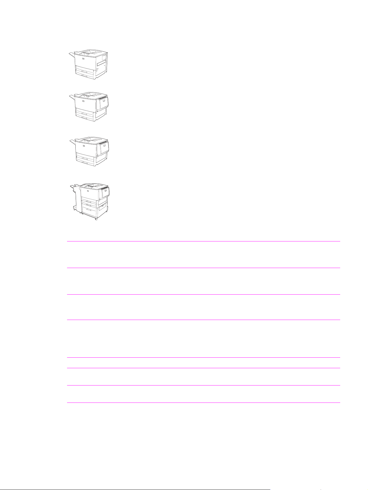
Product features of the HP LaserJet 9000 Series printers
HP LaserJet 9000 printer (C8519A)
The HP LaserJet 9000 printer comes standard with 64 MB RAM, wide-format
printing, and two 500-sheet trays (tray 2 and tray 3).
HP LaserJet 9000n printer (C8520A)
The HP LaserJet 9000n printer comes standard with 64 MB RAM, wide-format
printing, two 500-sheet trays (tray 2 and tray 3), a 100-sheet multipurpose tray
(optional tray 1), and an embedded HP Jetdirect print server.
HP LaserJet 9000dn printer (C8521A)
The HP LaserJet 9000dn printer comes standard with 64 MB RAM, wide-format
printing, two 500-sheet trays (tray 2 and tray 3), a 100-sheet multipurpose tray
(optional tray 1), an embedded HP Jetdirect print server, and an optional duplex
printing accessory (duplexer) for printing on both sides of paper.
HP LaserJet 9000hns printer (C8522A)
The HP LaserJet 9000hns printer contains the HP LaserJet 9000dn with a 2,000sheet feeder (optional tray 4) and an optional 3,000-sheet stapler/stacker, an
optional 3,000-sheet stacker, or an optional multifunction finisher.
Table 1. Features of the HP LaserJet 9000 Series printers
Speed
Resolution z 600 dots per inch (dpi) with Resolution Enhancement technology (REt).
Toner
PCL printer
language and fonts
PS language
Automatic language
switching
Enhanced memory
and memory expansion
z 50 pages per minute (ppm) for letter-size print media and A4-s ize media.
z First page out in less than 8 seconds.
z Transmit Once, Raster Image Processing (RIP) Once technology.
z HP FastRes 1200 (1200-dpi-like quality at up to 50 ppm letter and A4).
z Up to 256 levels of gray.
z HP UltraPrecise print cartridge. The capacity is rated at an average
30,000 pages with 5% coverage.
z EconoMode capability.
z Fast printing performance, built-in Intellifont and TrueType
technologies, built-in HP-GL/2 vector graphics, and advanced imaging
capabilities are benefits of the printer control language (PCL) 6 printer
language. PCL 6 also includes 80 scalable TrueType fonts and one
bitmapped Line Printer Font.
z PostScript
z The printer automatically determines and switches to the appropriate
language for the print job.
z The HP LaserJet 9000 Series printers come with 64 MB of memory and
can be expanded to 384 MB.
®
3 (PS) emulation.
scaling
2 Chapter 1 Product information
Page 19

Table 1. Features of the HP LaserJet 9000 Series printers (continued)
Expandability All models accept the following accessories:
z Optional tray 1, a 100-sheet or 10-envelope multipurpose tray for
automatic and manual feeding of envelopes, labels, transparencies,
custom-sized media from 98 x 191 mm (3.8 x 7.5 inches) to
312 x 470 mm (12.3 x 18.5 in), and heavy paper.
z Optional tray 4, a 2,000-sheet feeder that supports letter, legal, B4, A4,
11 x 17 inches, A3, executive, B5, and custom 182 x 210 mm
(7.2 x 8.3 inches) to 297 x 431.8 mm (11.7 x 17 inches) print media.
z Optional duplexer.
z Optional 3,000-sheet stapler/stacker, 3,000-sheet stacker, or
multifunction finisher.
z Enhanced input/output (EIO) cards.
z Dual inline memory module (DIMM) slots for adding memory and fonts.
z Hard disk for RIP Once capability, job retention features, and font
storage.
Wireless printing
Interface connecti on z Bidirectional ECP type-C parallel port (IEEE-1284 compliant).
z The printer supports wireless printing with the installation of a Fast
InfraRed Connect pod.
z Three EIO slots for hard-disk-accessor y or print-server installation.
z Wireless Fast InfraRed port (IrDA compliant).
z Foreign interface connector.
z HP Jet-Link connector.
Networking
Duty cycle
z Three EIO slots for hard-disk-accessor y or print-server installation.
z An HP 610N Jetdirect print server is included with HP LaserJet 9000n,
9000dn, and 9000hns.
z 300,000 images per month.
Product features of the HP LaserJet 9000 Series printers 3
Page 20

Product features of the HP LaserJet 9040/9050 Series printers
HP LaserJet 9040/9050 printe r
The HP LaserJet 9040/9050 printer (product number Q7697A/Q3721A) comes
standard with 64 MB RAM, wide-format printing, and two 500-sheet trays (tray 2
and tray 3).
HP LaserJet 9040n/9050n printer
The HP LaserJet 9040n/9050n printer (product number Q7698A/Q3722A) comes
standard with 128 MB RAM, wide-format printing, two 500-sheet trays (tray 2 and
tray 3), a 100-sheet multipurpose tray (tray 1), and an embedded HP Jetdirect print
server.
HP LaserJet 9040dn/9050dn printer
The HP LaserJet 9040dn/9050dn printer (product number Q7699A/Q3723A)
comes standard with 128 MB RAM, wide-format printing, two 500-sheet trays
(tray 2 and tray 3), a 100-sheet multipurpose tray (tray 1), an embedded HP
Jetdirect print server, and a duplex printing accessory (duplexer) for printing on
both sides of paper.
Table 2. Features of the HP LaserJet 9040/9050 Series printers
Speed
Resolution z 600 dpi with REt.
Toner
PCL printer
language and fonts
PS language
Automatic language
switching
Enhanced memory
and memory expansion
z 40 pages per minute (ppm) (HPLaserJet 9040 series printer) or 50 ppm
(HP LaserJet 9050 series printer) on letter or ISO A4 paper.
z First page out in less than 8 seconds.
z Transmit Once, RIP Once technology.
z FastRes 1200 provides 1200 dpi quality at full speed.
z Up to 256 levels of gray.
z HP UltraPrecise print cartridge. The capacity is rated at an average
30,000 pages with 5% coverage.
z EconoMode capability.
z Fast printing performance, built-in Intellifont and TrueType scaling
technologies, built-in HP-GL/2 vector graphics, and advanced imaging
capabilities are benefits of the printer control language (PCL) 6 printer
language. PCL 6 also includes 80 scalable TrueType fonts and one
bitmapped Line Printer Font.
z PostScript 3 (PS) emulation.
z The printer automatically determines and switches to the appropriate
language for the print job.
z The HP LaserJet 9040/9050 Series printers come with 64 or 128 MB of
memory and can be expanded to 512 MB.
4 Chapter 1 Product information
Page 21

Table 2. Features of the HP LaserJet 9040/9050 Series printers (continued)
Expandability All models accept the following accessories:
z Optional tray 1, a 100-sheet or 10-envelope multipurpose tray for
automatic and manual feeding of envelopes, labels, transparencies,
custom-sized media from 98 x 191 mm (3.8 x 7.5 inches) to
312 x 470 mm (12.3 x 18.5 inches), and 64 to 216 g/m² (17- to 58-lb
bond).
z Optional tray 4, a 2,000-sheet feeder that supports letter, legal, B4, A4,
11 x 17 inches, A3, executive, B5, and custom 76 x 127 mm
(3 x 5 inches) to 297 x 431 mm (11.7 x 17 inches) print media.
z Optional duplexer.
z Optional 3,000-sheet stapler/stacker, 3,000-sheet stacker, multifunction
finisher, or 8-bin mailbox.
z EIO cards.
z DIMM slots for adding memory.
z Hard disk for RIP Once capability, job retention features, and font
storage.
z Compact Flash slots for printer firmware forms or fonts.
Wireless printing z The printer supports wireless printing with the installation of a Fast
InfraRed Connect pod.
Interface connecti on z Bidirectional ECP type-B parallel port (IEEE-1284 compliant).
z Two EIO slots for accessory installation.
z HP Jet-Link connector.
Networking
z Two EIO slots for hard-disk-access ory or print server installation.
z A Jetdirect print server is included with HP LaserJet 9040n/9050n and
9040dn/9050dn.
Duty cycle z 300,000 images per month.
Product features of the HP LaserJet 9040/9050 Series printers 5
Page 22
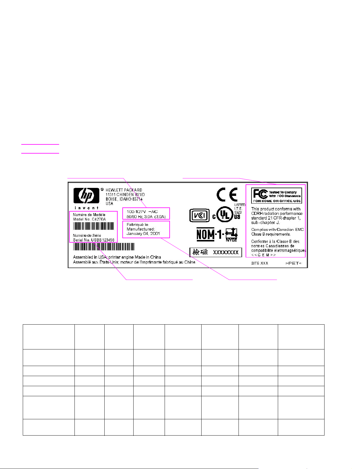
Product specifications
Identification
The model number and printer serial number are listed on an identification label located in two
places:
z on the rear cover
z on the chassis behind the right door
The model number is alphanumeric, such as C4270A.
The serial number contains information about the country/region of origin and the revision level, the
production code, and production number of the printer. An example of a serial number is
USBB123456.
The top label also contains power-rating and regulatory information. See figure 1.
Note The power-rating and regulatory information varies by country/region.
Electrical information Regional certification
Model and serial number
Manufacture date
Figure 1. Sample identification label
Table 3. Configuration comparison
HP
LaserJet
9000
Standard memory
Maximum memory
PS emulation Standard Standard Standard Standard Standard Standard Standard
Jetdirect print server Optional Standard Standard Standard Optional Standard Standard
Optional duplexer Optional Optional Standard Standard Optional Optional Standard
Optional tray 1,
100-sheet
multipurpose tray
Optional tray 4,
2,000-sheet feeder
64 MB
384 MB
Optional Standard Standard Standard Optional Standard Standard
Optional Optional Optional Standard Optional Optional Optional
HP
LaserJet
9000n
64 MB
384 MB
HP
LaserJet
9000dn
64 MB
384 MB
HP
LaserJet
9000hns
64 MB
384 MB
HP
LaserJet
9040/9050
64 MB
512 MB
HP
LaserJet
9040n/9050n
128 MB
512 MB
HP
LaserJet
9040dn/9050dn
128 MB
512 MB
6 Chapter 1 Product information
Page 23
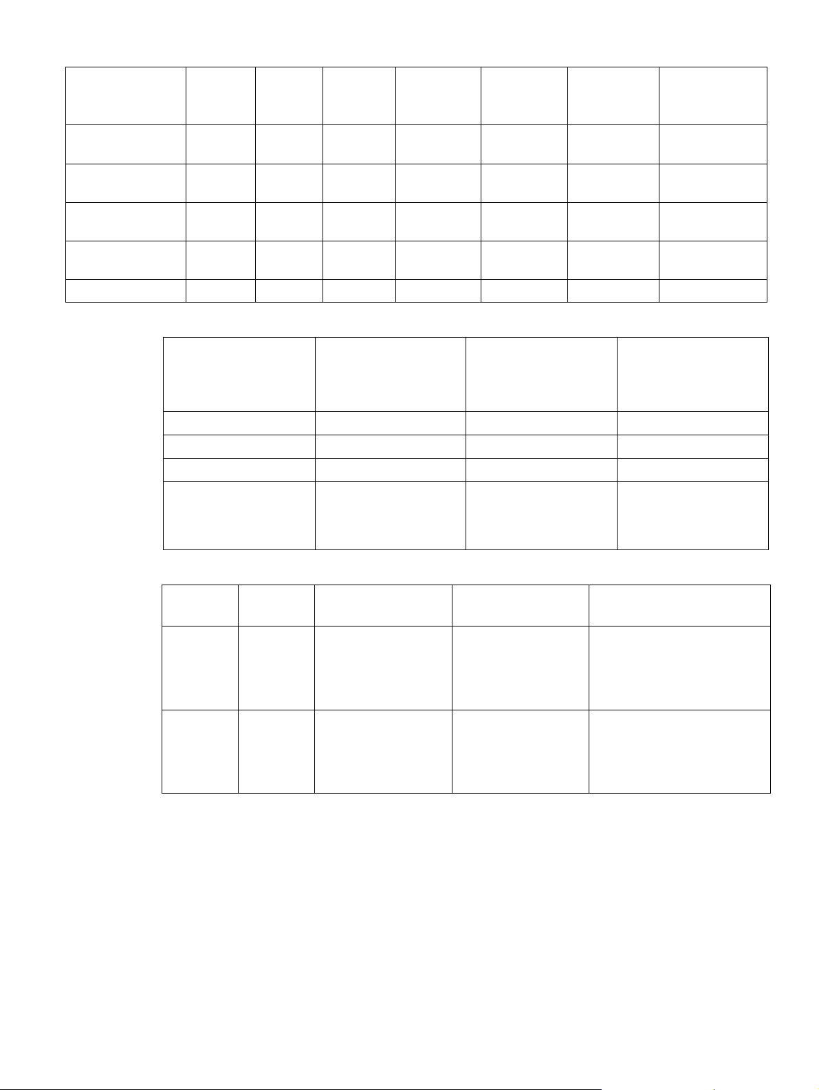
Table 3. Configuration comparison
HP
LaserJet
9000
Optional 3,000sheet stacker
Optional 3,000sheet stapler/stacker
Optional
multifunction finisher
Optional 8-bin
mailbox
Optional hard disk Optional Optional Optional Optional Optional Optional Optional
Optional Optional Optional Optional Optional Optional Optional
Optional Optional Optional Standard Optional Optional Optional
Optional Optional Optional Optional Optional Optional Optional
N/A N/A N/A N/A Optional Optional Optional
HP
LaserJet
9000n
HP
LaserJet
9000dn
HP
LaserJet
9000hns
HP
LaserJet
9040/9050
HP
LaserJet
9040n/9050n
HP
LaserJet
9040dn/9050dn
Table 4. Physical specifications
HP LaserJet
9000, 9040, and 9050
HP LaserJet
9000n/9000dn,
HP LaserJet
9000hns
9040n/9040dn, and
9050n/9050dn
Height 600 mm (23.6 inches) 600 mm (23.6 inches) 1,036.4 mm (40.8 inches)
Width 990.8 mm (39.0 inches) 1,115.8 mm (44.4 inches) 1,788.2 mm (70.4 inches)
Depth 1,001 mm (42.7 inches) 1,001 mm (42.7 inches) 1,001 mm (42.7 inches)
Weight
(without print cartridge)
63.5 kg (140 lb) 9000n/9040n/9050n:
69.4 kg (153 lb)
9000dn/9040dn/9050dn:
76.2 kg (168 lb)
76.2 kg (168 lb)
Table 5. Electrical specifications (HP LaserJet 9000)
Volts Frequency Amperes (A) Watts (W) (typical) Thermal units per hour
(BTu/hr)
100-127 V ac
± 10%
220-240 V ac
± 10%
50/60 Hz
± 2 Hz
50/60 Hz
± 2 Hz
Minimum
recommended current
capacity =
15 A dedicated circuit
Minimum
recommended current
capacity =
6.5 A dedicated circuit
printing = 1,040 W
standby = 265 W
PowerSave 1 = 40 W
PowerSave 2 = 25 W
off = 0 W
printing = 995 W
standby = 265 W
PowerSave 1 = 40 W
PowerSave 2 = 25 W
off = 0.2 W
printing = 3,550.36 BTU/hr
standby = 904.71 BTU/hr
PowerSave 1 = 136.56 BTU/hr
PowerSave 2 = 85.35 BTU/hr
off = 0 BTU/hr
printing = 3,396.93 BTU/hr
standby = 904.71 BTU/hr
PowerSave 1 = 136.56 BTU/hr
PowerSave 2 = 85.35 BTU/hr
off = 0.69 BTU/hr
Product specifications 7
Page 24
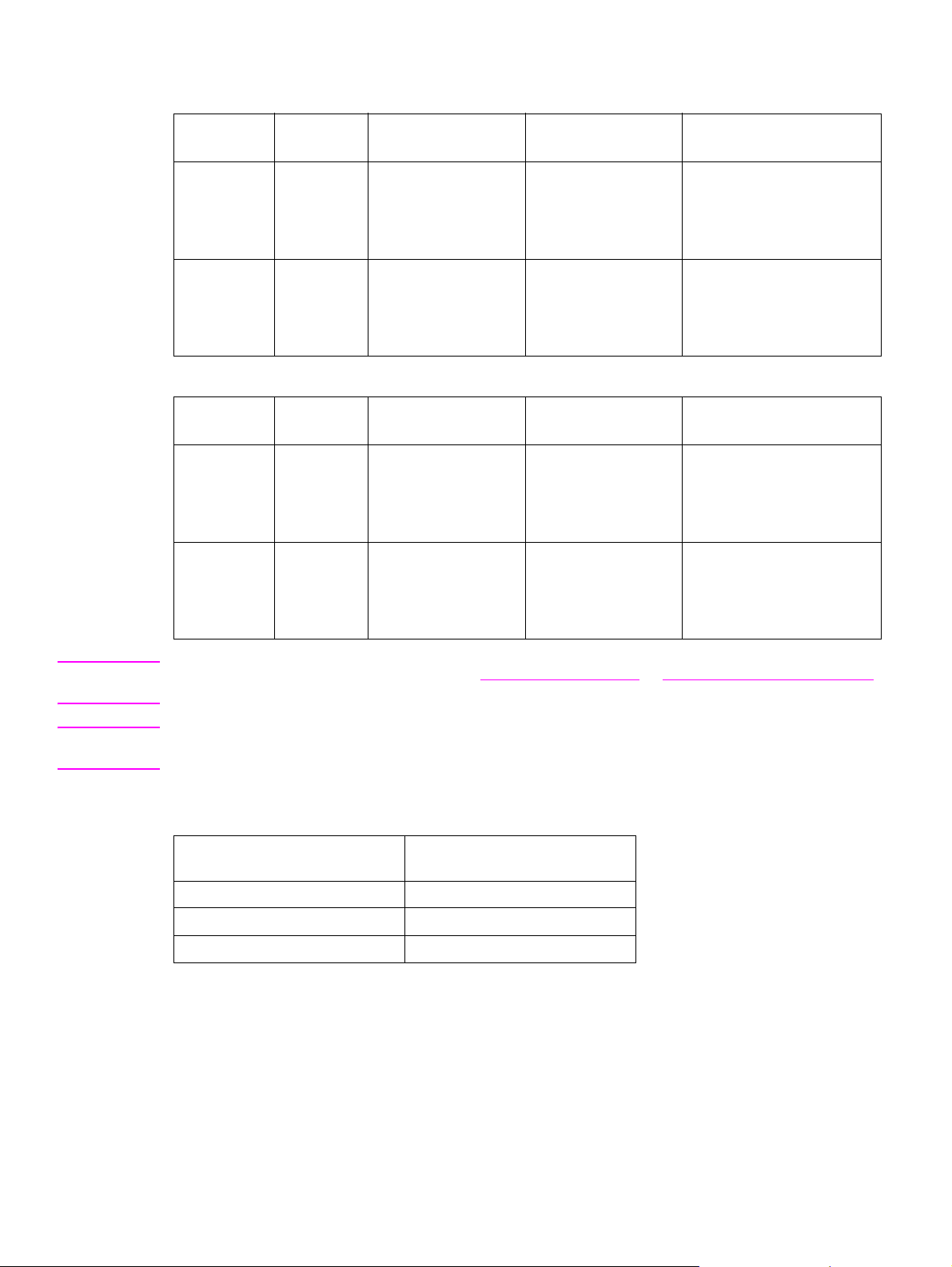
Table 6. Electrical specifications (HP LaserJet 9040)
Volts Frequency Ampres Watts (W) (typical) Therma l units per hour
(BTu/hr)
100-127 V ac ±
10%
220-240 V ac ±
10%
50/60 Hz
± 2 Hz
50/60 Hz
± 2 Hz
Minimum
recommended current
capacity =
12 A dedicated circuit
Minimum
recommended current
capacity =
5.3 A dedicated circuit
printing = 900 W
standby = 200W
PowerSave 1 = 158 W
PowerSave 2 = 21 W
off = 0.5 W
printing = 900 W
standby = 200 W
PowerSave 1 = 40 W
PowerSave 2 = 21 W
off = 0.5 W
printing = 3,550.36 BTu/hr
standby = 904.71 BTu/hr
PowerSave 1 = 136.56 BTu/hr
PowerSave 2 = 85.35 BTu/hr
off = 0 BTu/hr
printing = 3,396.93 BTu/hr
standby = 904.71 BTu/hr
PowerSave 1 = 136.56 BTu/hr
PowerSave 2 = 85.35 BTu/hr
off = 0.69 BTu/hr
Table 7. Electrical specifications (HP LaserJet 9050)
Volts Frequency Ampres Watts (W) (typical) Therma l units per hour
(BTu/hr)
100-127 V ac ±
10%
220-240 V ac ±
10%
50/60 Hz
± 2 Hz
50/60 Hz
± 2 Hz
Minimum
recommended current
capacity =
12 A dedicated circuit
Minimum
recommended current
capacity =
6.5 A dedicated circuit
printing = 1,000 W
standby = 200 W
PowerSave 1 = 158 W
PowerSave 2 = 21 W
off = 0.5 W
printing = 1,000 W
standby = 200 W
PowerSave 1 = 40 W
PowerSave 2 = 21 W
off = 0.5 W
printing = 3,550.36 BTu/hr
standby = 904.71 BTu/hr
PowerSave 1 = 136.56 BTu/hr
PowerSave 2 = 85.35 BTu/hr
off = 0 BTu/hr
printing = 3,396.93 BTu/hr
standby = 904.71 BTu/hr
PowerSave 1 = 136.56 BTu/hr
PowerSave 2 = 85.35 BTu/hr
off = 0.69 BTu/hr
Note Electrical specifications might change. See www.hp.com/go/lj9000 or www.hp.com/go/lj9050_lj9040
for the current information.
WARNING! Power requirements are based on the country/region where the printer is sold. Do not convert operating
voltages. This can damage the printer and void the product warranty.
Table 8. Environmental specifications
Operating temperature 10°C to 32.5°C
°F to 91°F)
(50
Relative humidity 10% to 80%
Storage temperature -40ºF to +60ºF
Storage humidity 15% to 90%
8 Chapter 1 Product information
Page 25

Table 9. Acoustical specifications
Declared per ISO 9296
Sound power level
1
Printing (50 ppm) L
= 7.2 Bels (A) [72 dB(A)]
WAd
HP LaserJet 9050
= 5.6 Bels (A) [56 dB(A)]
WAd
= 7.0 Bels (A) [dB(A)]
WAd
= 5.6 Bels (A) [dB(A)]
WAd
= 56 dB(A)
pAm
Sound power level
2
HP LaserJet 9040
Sound pressure level
Ready L
Printing (40 ppm) L
Ready L
3
Printing (50 ppm) L
(Bystander position)
HP LaserJet 9050
Sound pressure level
(Bystander position)
Ready L
4
Printing (40 ppm) L
= 40 dB(A)
pAm
= 54 dB(A)
pAm
HP LaserJet 9040
Ready L
= 39 dB(A)
pAm
1.Values current as of October 16, 2003. Values subject to change, see
lj9050_lj9040 for current information.
2.Values current as of October 24, 2004. Values subject to change, see
lj9050_lj9040 for current information.
3.Values current as of October 16, 2003. Values subject to change, see
lj9050_lj9040 for current information.
4.Values current as of October 24, 2004. Values subject to change, see
lj9050_lj9040 for current information.
www.hp .com/support/
www.hp.com/support/
www.hp .com/support/
www.hp.com/support/
Product specifications 9
Page 26
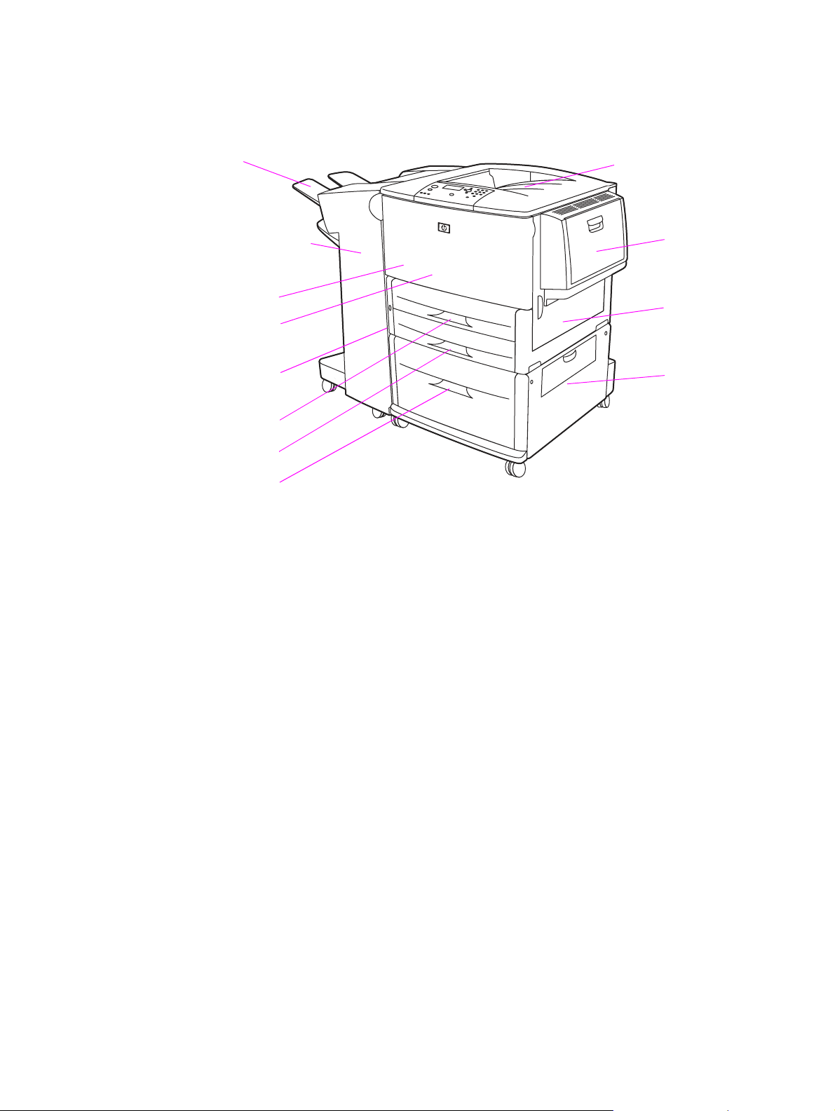
Product overview
External view of the printer and accessories
Face-up bin
Optional 3,000-sheet
stapler/stacker, 3,000sheet stacker, 8-bin
mailbox, or
multifunction finisher
Front door
Duplexer (inside
the printer)
Left door
(behind the
output
Tr ay 2
Tr ay 3
Optional tray 4
Figure 2. External view of the printer and accessories
Standard output bi n
(face-down bin)
Optional
tray 1
Right door
Vertical
transfer door
10 Chapter 1 Product information
Page 27
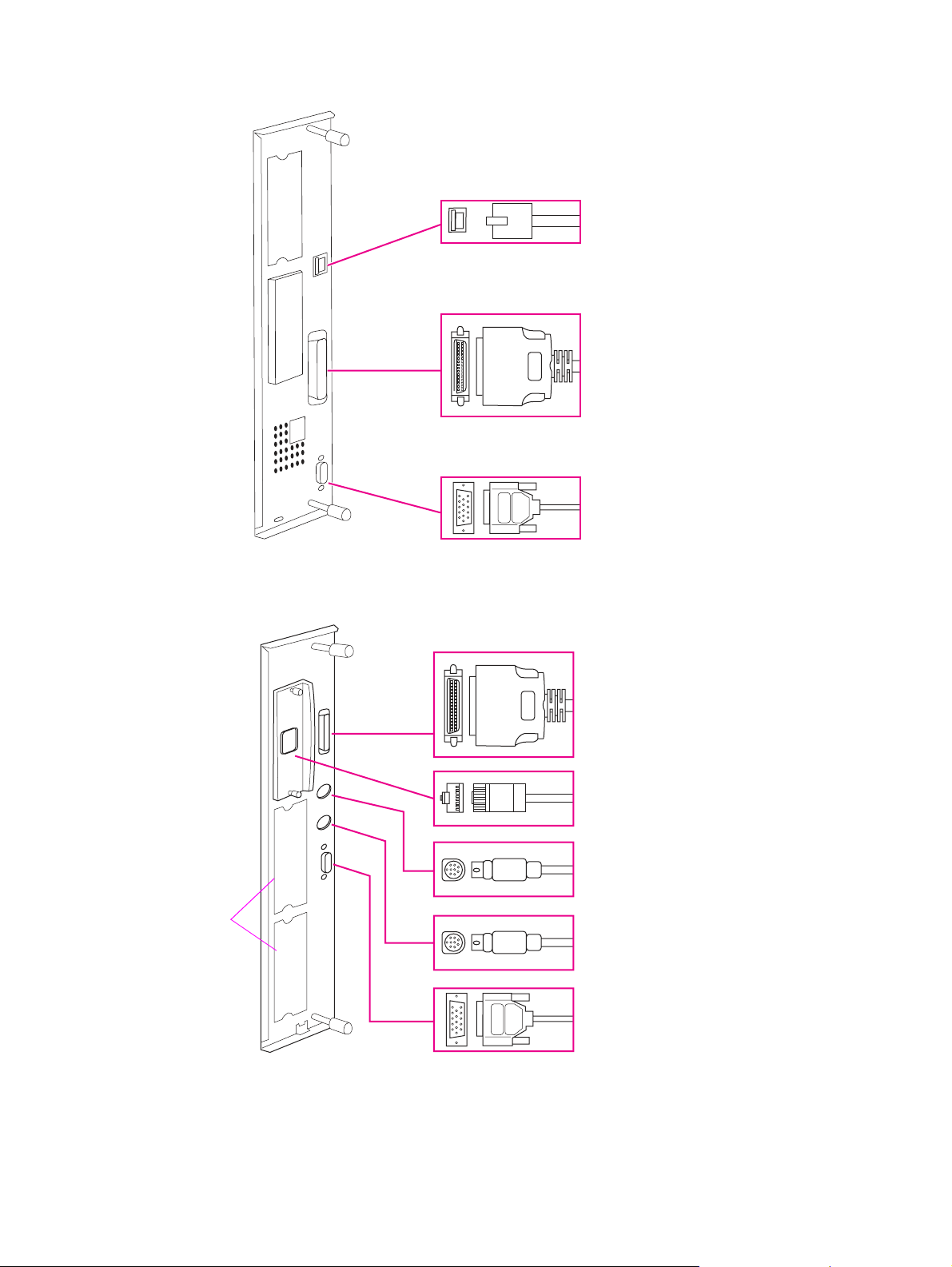
Interface connections
Local area network (LAN)
connector (RJ-45)
Parallel B connector
(Parallel)
HP Jet-Link connector
(for paper-handling
accessory)
Figure 3. Interface connections (HP LaserJet 9040/9050 Series printer)
Parallel connector
HP Jetdirect print server
(optional)
Foreign interface
connector (not used)
I/O
slots
HP Fast InfraRed Connect
(optional IR pod)
HP Jet-Link connector
(optional accessories
connection)
Figure 4. Interface connections (HP LaserJet 9000 Series printer)
Product overview 11
Page 28
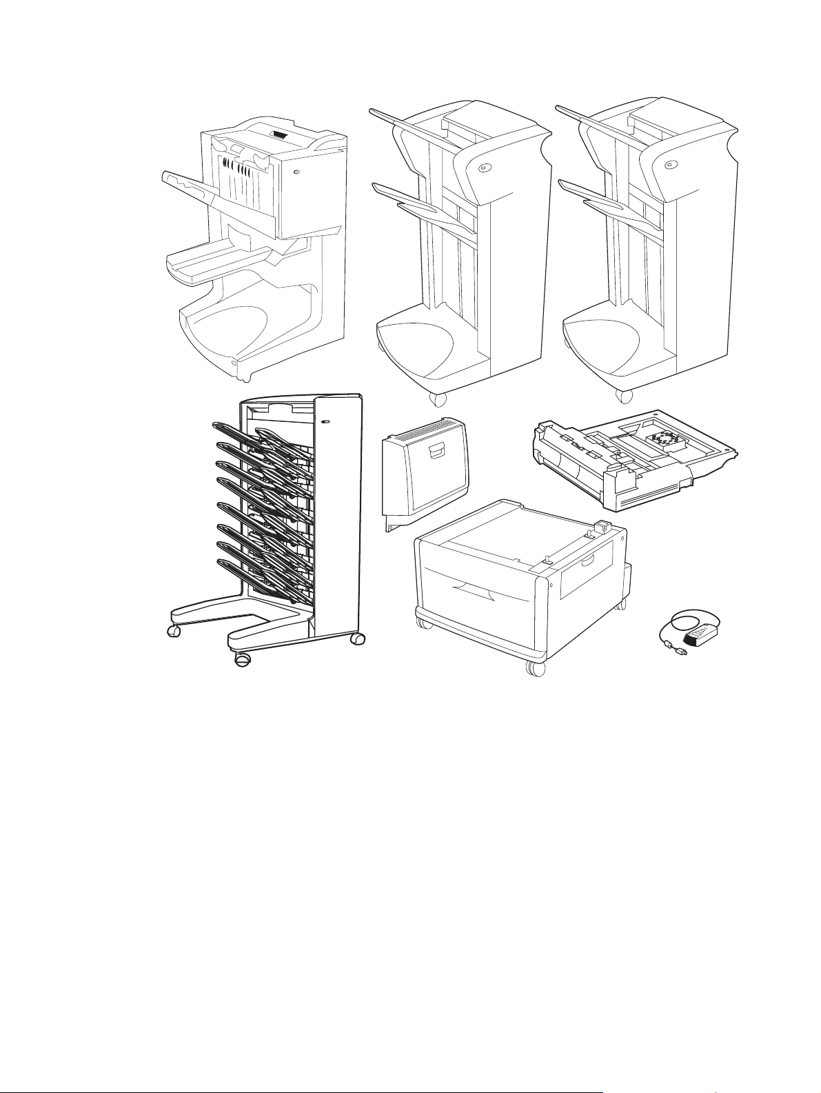
Optional accessories
Multifunction finisher
3,000-sheet stapler/stacker
3,000-sheet stacker
Figure 5. Optional accessories
8-bin mailbox
(HP LaserJet
9040/9050 Series
printer only)
Tray 4
Tray 1
Duplex printing
accessory
(duplexer)
HP Fast InfraRed
Connect (HP LaserJet
9000 Series printer only
12 Chapter 1 Product information
Page 29

Regulatory information
Regulatory requirements
For regulatory information and requirements, please see the HP LaserJet 9000 Start Guide or the
HP LaserJet 9040/9050 Start Guide.
FCC regulations
For FCC regulations, please see the HP LaserJet 9000 Start Guide or the HP LaserJet 9040/9050
Start Guide.
Declaration of conformity
For declaration of conformity information, please see the HP LaserJet 9000 Start Guide or the HP
LaserJet 9040/9050 Start Guide.
Environmental product stewardship program
For environmental product stewardship program information, please see the HP LaserJet 9000 Use
Guide or the HP LaserJet 9040/9050 Use Guide.
Regulatory information 13
Page 30

Service approach
Repair of the printer normally begins with a three-step process:
z isolate the problem to the major system (the host computer, the network and/or server, or the
printer system)
z determine whether the problem is located in one of the paper-handling devices or in the printer
engine
z troubleshoot the problem using the procedures in chapter 7
When a faulty part is located, repair is usually accomplished by assembly-level replacement of field
replaceable units (FRUs). Some mechanical assemblies can be repaired at the subassembly level.
Hewlett-Packard does not support replacement of components on the printed circuit assemblies.
Parts and supplies
The following information helps you locate parts and assistance.
Ordering information
"Ordering parts" in chapter 8 of this manual contains FRUS and replacement part numbers.
Replacement parts can be ordered from the HP Customer Services and Support Organization
(HPS).
"Consumables, supplies, accessories, FRUs, and documentation" in chapter 8 of this manual
contains information about accessories that are specifically designed for this printer. Order
accessories from HPS.
Phone listings
z HPS (for U. S.)
(800) 752-0900
z HPS (for Canada)
(800) 387-3867
z HPS (for Europe)
(49 7031) 142253
Exchange program
Hewlett-Packard offers remanufactured assemblies for some parts. These are identified in
"Illustrations and parts lists" in chapter 8, and can be ordered through HPS.
Consumables
The printer has two consumables: the print cartridge and the preventive maintenance kit. The
stapler/stacker and the 8-bin mailbox have one consumable: the staple cartridge. These are
identified in "Illustrations and parts lists" in chapter 8, and can be ordered through HPS.
Warranty
For warranty information and requirements, please see the HP LaserJet 9000 Start Guide or the HP
LaserJet 9040/9050 Start Guide.
Limited warranty for print-cartridge life
For print-cartridge warranty information, please see the HP LaserJet 9000 Start Guide or the HP
LaserJet 9040/9050 Start Guide.
14 Chapter 1 Product information
Page 31

2 Product requirements
Chapter contents
Site requirements . . . . . . . . . . . . . . . . . . . . . . . . . . . . . . . . . . . . . . . . . . . . . . . . . . . . . . . . . . . . .16
Operating environment . . . . . . . . . . . . . . . . . . . . . . . . . . . . . . . . . . . . . . . . . . . . . . . . . . . . . .16
Space requirements . . . . . . . . . . . . . . . . . . . . . . . . . . . . . . . . . . . . . . . . . . . . . . . . . . . . . . . .17
Media specifications . . . . . . . . . . . . . . . . . . . . . . . . . . . . . . . . . . . . . . . . . . . . . . . . . . . . . . . . . . .19
Guidelines for selecting print media . . . . . . . . . . . . . . . . . . . . . . . . . . . . . . . . . . . . . . . . . . . .19
Special media specifications. . . . . . . . . . . . . . . . . . . . . . . . . . . . . . . . . . . . . . . . . . . . . . . . . .19
Storing print media . . . . . . . . . . . . . . . . . . . . . . . . . . . . . . . . . . . . . . . . . . . . . . . . . . . . . . . . .22
Media input/output options . . . . . . . . . . . . . . . . . . . . . . . . . . . . . . . . . . . . . . . . . . . . . . . . . . . . . .25
Trays, bins, and paper handling . . . . . . . . . . . . . . . . . . . . . . . . . . . . . . . . . . . . . . . . . . . . . . .25
Chapter contents 15
Page 32

Site requirements
Operating environment
The electrical and environmental specifications must be maintained to ensure the proper operation of
this printer. See "Product specifications" in chapter 1. Consider the following points before installing
the printer:
z Install in a well-ventilated, dust-free area.
z Install on a level, flat surface that can support the printer size and weight. Make sure that all four
printer feet are level. Do not install on carpet or on other soft surfaces.
z Make sure that an adequate power-supply circuitry is available. See "Product specifications" in
chapter 1.
z Install where temperature and humidity are stable, and where no abrupt changes occur (away
from water sources, humidifiers, air conditioners, refrigerators, or other major appliances). See
"Product specifications" in chapter 1.
z Install away from direct sunlight, areas that experience vibration, open flames, ultrasonic heaters,
ammonia fumes, or magnets and devices that emit a magnetic field. If the printer is placed near
a window, make sure that the window has a curtain or blind to block direct sunlight.
z Maintain enough space around the printer for proper access and ventilation. See "Space
requirements" on page 17.
16 Chapter 2 Product requirements
Page 33

Space requirements
353 mm
(13.9 inches)
353 mm
(13.9 inches)
638 mm (25.1 inches)
638 mm (25.1 inches)
633 mm (24.9 inches)
(17.8 inches)
368 mm
Figure 6. Space requirements for the base model
600 mm (23.6 inches)
Site requirements 17
Page 34

2,591 mm (102 inc hes)
2,591 mm (102 inches)
1,001 mm (39.4 inches)
1,036 mm (40.8 inches)
Figure 7. Space requirements with a finishing device (3,000-sheet stapler/stacker shown) and tray 4
installed
18 Chapter 2 Product requirements
Page 35

Media specifications
Use the following information to help the user select and use print media.
Note Before purchasing large quantities of print media, make sure that it meets the requirements that are
specified in this service manual and in the HP LaserJet Printer Family Print Media Guide. See "Media
input/output options" on page 25. Always test print media before buying large quantities.
Note Hewlett-Packard neither warrants nor recommends the use of a particular brand of paper or print media.
Media properties are subject to manufacturing changes, and HP has no control over such changes.
Although testing media helps to characterize the manufacturer’s performance and process quality, the
customer assumes all responsibility for the quality and performance of media.
Guidelines for selecting print media
For best results, use conventional 75-g/m2 (20-lb) paper. Make sure that the paper is of good quality,
and free of cuts, nicks, tears, spots, loose particles, dust, wrinkles, voids, and curled or bent edges.
Note Some print media might meet all of the guidelines in this manual and still not produce satisfactory
results. This might be the result of improper handling, unacceptable temperature and humidity levels,
or other variables over which HP has no control.
If you are unsure what type of paper you are loading (such as bond or recycled), check the label on
the package of paper.
For information about measuring caliper, see "Media input/output options" on page 25.
Hint Do not purchase more media than can be easily used in a short time (about 3 months). Media that is
stored for long periods experiences heat and moisture extremes that can be damaging. Planning is
important to prevent damage to a large supply of media.
Special media specifications
The following sections describe specifications for special media that can be used in these printers.
Envelope specifications
Successful printing on envelopes depends upon the quality of the envelopes. Envelope fold lines can
vary considerably, not only between manufacturers, but also within a box from the same
manufacturer. When selecting envelopes, consider the following components:
z Construction—Prior to printing, envelopes should lie flat with less than 10 mm (0.39 inch) curl,
and have well-constructed seams.
z Condition—Envelopes should not be wrinkled, nicked, or otherwise damaged.
z Temp e r a t ure—Envelopes should be compatible with the heat and pressure produced by the
printer.
Media specifications 19
Page 36

Figure 8. Sample seams
Note Print envelopes from tray 1 only. Send envelopes straight through the printer, entering at tray 1 and
exiting from the face-up bin.
Note For the best print quality, position margins no closer than 15 mm (0.6 inch) from the edges of the
envelope. A void printing over the area where the envelope seams meet.
Envelopes that have adhesive strips or flaps
Check to make sure that envelopes that have peel-off adhesive strips, or more than one flap that
folds over to seal, use adhesives that are compatible with the heat and pressure in the printer. The
extra flaps and strips might cause wrinkling, creasing, or jams, and can even damage the fuser.
Label specifications
CAUTION To avoid damaging the printer, use only labels that are recommended for laser printers. Never print on
the same sheet of labels more than once and never print on a partial sheet of labels.
When selecting labels, consider the quality of each component:
z Adhesives—The adhesive material should be stable at 190°C (374°F), which is the printer
fusing temperature.
z Arrangement—Do not use labels that have exposed backing between them. Labels can peel off
sheets with spaces between the labels, causing jams. See figure 9 for acceptable arrangement
schemes.
z Curl—Prior to printing, labels must lie flat with no more than 10 mm (0.39 inch) of curl in any
direction.
z Condition—Do not use labels that have wrinkles, bubbles, or other indications of separation.
Note Print labels from tray 1 only. Send labels straight through the printer, entering at tray 1 and exiting from
the face-up bin.
20 Chapter 2 Product requirements
Page 37

Figure 9. Adhesive labels
Transparency specifications
To avoid damaging the printer, use only transparencies that are recommended for use in laser
printers.
z Construction—Prior to printing, transparencies should lie flat with less than 10 mm (0.39 inch)
curl.
z Condition—Transparencies should not be wrinkled, nicked, or otherwise damaged.
z Temp e r a t ure—Transparencies should be stable at 190°C (374°F), which is the printer fusing
temperature.
Note If problems occur while printing transparencies, use tray 1. Send transparencies straight through the
printer, entering at tray 1 and exiting from the face-up bin.
CAUTION Transparencies that are used in the printer must be able to withstand 190°C (374°F), the printer fusing
temperature.
Preprinted forms and special letterhead
Many preprinted forms and special letterhead papers perform well in HP LaserJet printers. However,
these papers undergo processes that alter their original characteristics, and care must be taken to
ensure that they conform to HP specifications. All special papers should be wrapped in moistureproof wrapping when they are purchased from the paper converter or printing house.
Forms and letterhead must be printed with inks that conform to the following specifications:
z Only use ink that is heat-resistant, and that will not melt, scorch, or release hazardous emissions
when subjected to 200°C (392°F) for 0.1 second.
z Inks must have resistance to silicon oils, and must not be affected by resin components in toner.
z Inks must not be flammable.
z Inks must not “offset” (transfer from the printed paper onto the printer, contaminating internal
printer components). The principle cause of offset is ink that is not fully dried or that cannot
withstand the printer fusing temperature.
Note Do not use low-temperature inks (the kind that is used in thermography).
Media specifications 21
Page 38

Embossed media
Embossed media is not recommended for use in HP LaserJet printers. Media is embossed by
stamping an image into the media by compressing the media fibers together at approximately 200°C
(392°F), and sometimes by applying a thin metal foil to the surface. The printer fusing process can
loosen the foil, and loose foil can interfere with the mechanical and electronic operation of the printer.
Embossed paper, with or without foil, can also cause multifeed jams. Multiple embossed print media
sheets tend to stick to one another.
Media that contains cutouts or perforations
Avoid media that contains cutouts or perforations for these reasons:
z Cut fibers absorb more moisture and can increase waviness and media curl. This decreases the
print quality near the cutout or perforated area.
z Cutting knives leave a sharp edge on the cutout or perforation. If the sharp edge is facing the
print cartridge drum during printing, it can scratch the drum surface.
z If printing occurs over a cutout hole, the transfer roller is contaminated with unused toner,
creating light streaks on the paper.
Chemically treated media
Coatings such as lacquers, polymers, laminations, or other chemicals protect the paper, but can
cause problems in the fuser and transfer areas of HP LaserJet printers. The surface resistivity and
moisture content can be greatly altered, resulting in print-quality problems. Hard surface coatings
increase wear on the rollers and media guides. All chemically treated media must meet HP
specifications for fusing compatibility.
Synthetic media
Synthetic media (those manufactured from man-made fibers) do not perform as well as bond media
in any printer, especially HP LaserJet printers. All synthetic media must meet HP specifications,
especially for caliper and fusing compatibility.
Coated media
Do not use coated media. Most coated media does not meet the specifications for fusing
compatibility and other specifications for HP LaserJet printers.
Other special media
z Odd sizes: check minimum and maximum supported sizes in chapter 2.
z Carbonless media: carbonless media (NCR) is not supported by HP LaserJet printers.
z Recycled media: choose recycled media that meets Hewlett-Packard specifications. Note that
recycled media might not be as bright as indicated in the specifications. HP recommends that
recycled media contain no more than 5% groundwood. See "Paper weight equivalence table" on
page 23.
Storing print media
Ideally, the printing and media storage environment should be at or near room temperature, and
should not be too dry or too humid. Remember that paper is hygroscopic; it absorbs and loses
moisture rapidly.
Heat works with humidity to damage paper. Heat causes the moisture in paper to evaporate, while
cold causes it to condense on the sheets. Heating systems and air conditioners remove most of the
humidity from a room. As a package is opened and used the paper is used, it loses moisture, causing
22 Chapter 2 Product requirements
Page 39

streaks and smudging. Humid weather or water coolers can cause the humidity in a room to
increase. As a package of paper is opened and used, it absorbs any excess moisture, causing light
print and dropouts. Also, as paper loses and gains moisture, it can distort. This can cause jams.
Therefore, print-media storage and handling are as important as the paper-making process itself.
Media storage environmental conditions directly affect the feed operation.
Customers should not purchase more media than can easily be used in a short time (about three
months). Media that is stored for long periods might experience heat and moisture extremes, which
can cause damage. Planning is important to prevent damage to a large supply of media.
Unopened paper in sealed packages can remain stable for several months before use. Opened
packages of paper have more potential for environmental damage, especially if they are not wrapped
with a moisture-proof barrie r.
The media storage environment should be properly maintained to ensure optimum printer
performance. The required condition is 20°C to 24°C (68°F to 75°F), with a relative humidity of 45%
to 55%. The following guidelines should be helpful when evaluating the paper-storage environment:
z Paper should be stored at or near room temperature.
z The air should not be too dry or too humid (because of the hygroscopic properties of paper).
z The best way to store an opened package of paper is to rewrap it tightly in its moisture-proof
wrapping. If the printer environment is subject to extremes, unwrap only the amount of paper to
be used during the day's operation to prevent unwanted moisture changes.
Envelope storage
Proper storage of envelopes contributes to good print quality. Env elopes should be stored flat. If air is
trapped in an envelope, and creates an air bubble, then the envelope might wrinkle during printing.
Paper weight equivalence table
Use this table to determine approximate equivalent points in weight specifications other than U.S.
bond weight. For example, to determine the equivalent of 20-lb U.S. bond-weight paper in U.S. coverweight paper, locate the bond weight (in row 3, second column) and scan across the row to the cover
weight (in the fourth column). The equivalent is 28 lb. Shaded areas indicate a standard weight for
that grade.
Table 10. Paper weight equivalence
U.S. postcard
thickness
(mm)
U.S. bond
weight (lb)
U.S. text/
book
weight (lb)
U.S. cover
weight (lb)
U.S. bristol
weight (lb)
U.S. index
weight (lb)
U.S. tag
weight (lb)
Europe
metric
weight
2
(g/m
17 43 24 29 35 39 64 64
20 50 28 34 42 46 75 75
21 54 30 36 44 49 80 80
22 56 31 38 46 51 81
24 60 33 41 50 55 90 90
27 68 37 45 55 61 100 100
28 70 39 49 58 65 105 105
Japan
metric
weight
)
(g/m2)
81
32 80 44 55 67 74 120 120
34 86 47 58 71 79 128
128
36 90 50 62 75 83 135 135
0.18 39 100 55 67 82 91 148 148
0.19 42 107 58 72 87 97 157
157
0.20 43 110 60 74 90 100 163 163
Media specifications 23
Page 40

Table 10. Paper weight equivalence
U.S. postcard
thickness
(mm)
U.S. bond
weight (lb)
U.S. text/
book
weight (lb)
U.S. cover
weight (lb)
U.S. bristol
weight (lb)
U.S. index
weight (lb)
U.S. tag
weight (lb)
0.23 47 119 65 80 97 108 176 176
53 134 74 90 110 122 199 199
54 137 75 93 113
58 146
80 98 120 133 216 216
125 203 203
65 165 90 111 135 150 244 244
66 169 92 114 138 154
67 171 94 115
140 155 253 253
70 178 98 120 146 162 264 264
72 183
100 123 150 166 271 271
Note The U.S. postcard measurements are approximate. Use for reference only.
Europe
metric
weight
2
(g/m
Japan
metric
weight
)
(g/m2)
250 250
24 Chapter 2 Product requirements
Page 41

Media input/output options
Trays, bins, and paper handling
The base-model printer comes with two built-in 500-sheet trays (tray 2 and tray 3). Tray 1 and tray 4
can be added to the printer. Special media (envelopes, labels) should only be loaded into tray 1. The
printer comes with face-up and face-down bins, and a 3,000-sheet stapler/stacker, 3,000-sheet
stacker, or multifunction finisher, or 8-bin mailbox for the HP LaserJet 9040/9050 Series printers, can
be installed.
Fa c e - up bi n
3,000-sheet st apler/
stacker, 3,000-sheet
stack er , multifu nction
finisher, or 8-bin
mailbox
Tr ay 2
Tr ay 3
Tr ay 4
Figure 10. Media trays, bins, and paper handling
CAUTION Using print media that does not meet HP specifications might cause problems for the printer, requiring
repair. Such repair is not covered by the Hewlett-Packard warranty or service agreements.
Standard output bin
(Face-down bin)
Tr ay 1
The HP LaserJet 9000 Series printers and HP LaserJet 9040/9050 Series printers accept a variety
of media, such as cut-sheet paper (including up to 100% recycled fiber-content paper), envelopes,
labels, transparencies, and custom-size paper. Properties such as weight, composition, grain, and
moisture content are important factors affecting printer performance and output quality. Media that
does not meet the guidelines outlined in this manual and in the print media guide can cause the
following problems:
z poor print quality
z increased jams
z premature wear on the printer, requiring repair
Media input/output options 25
Page 42

Supported sizes of paper for input and output
Note For more information on an optional HP output device, see the user guide that came with the product.
T ray or Bin Capacity Paper Weight
Optional tray 1 Up to
100 sheets
Up to
10 envelopes
Maximum
stack height f or
transparencies:
10 mm
(0.4 inch)
Trays 2 and 3 Up to
500 sheets
Standard detectab le sizes:
Letter, Legal, Executive, ISO A3, ISO
A4, ISO A5, 11 x 17, JIS B5, JIS B4,
JPostD,
Custom sizes:
Minimum: 98x 191 mm
(3.9 x 7.5 inches)
Maximum: 312 x 470 mm
(12.3 x 18.4 inches)
Envelope sizes:
Commercial #10, C5, DL, Monarch,
B5
Transparencies:
0.12 to 0.13 mm thick (4.7 to 5.5 mils
thick)
Note
Print on envelopes, transparencies,
and labels from optional tray 1 only.
Standard detectab le sizes:
Letter , Letter-R, Legal, Ex ecutiv e, ISO
A3, ISO A4-R, ISO A5, JIS B4, JIS
B5, 11 x 17
Custom sizes:
Minimum: 148x 210 mm
(5.8 x 8.3 inches)
Maximum: 297 x 431 mm
(11.7 x 17 inches)
64 to 216 g/m
(17- to 58-lb bond)
Two-sided printing: 64
to 199 g/m2 (1-7 to 53lb bond)
64 to 199 g/m
53-lb bond)
2
2
(17- to
Optional tray4 Up to
Standard top
bin
26 Chapter 2 Product requirements
2,000 sheets
Up to 500
sheets
Up to 50
transparencies
Standard detectab le sizes:
Letter, Legal, Executive, ISO A3, ISO
A4, 11 x 17, JIS B4, JIS B5
Standard undetectab le sizes:
8K, 16K, JIS Executive, 8.5 x 13
(215 x 330 mm)
Custom sizes:
Minimum: 182x 210 mm
(7.2 x 8.3 inches)
Maximum: 297 x 431 mm
(11.7 x 17 inches)
Standard sizes:
Letter, Legal, Executive, ISO A3, ISO
A4, ISO A5, 11 x 17, JIS B5, JIS B4,
JPostD, Monarch, 8K, 16K
Custom sizes
Custom types: Transparencies
64 to 199 g/m
53-lb bond)
64 to 199 g/m
53-lb bond)
2
(17- to
2
(17- to
Page 43

T ray or Bin Capacity Paper Weight
Left output bin Up to 100
sheets
Up to 10
transparencies
Duplex printing
accessory
Optional
3,000-sheet
stacker
Up to
3,000 sheets of
Letter or A4
Up to
1,500 sheets of
A3 or 11 x 17
Standard sizes:
Letter, Legal, Executive, ISO A3, ISO
A4, ISO A5, 11 x 17, JIS B5, JIS B4,
JPostD, Monarch, 8K, 16K
Custom sizes
Custom types: Envelopes, labels
Standard detectab le sizes:
Letter , Letter-R, Legal, Ex ecutiv e, ISO
A3, ISO A4, ISO A4-R, 11 x 17,
JIS B4, JIS B5
Standard undetectab le sizes:
8K, 16K
Custom sizes
Custom types: Duplexing is not
supported for envelopes, labels, or
transparencies.
Standard sizes for lower bin:
Letter, Legal, Executive, ISO A3, ISO
A4, ISO A5, 11 x 17, JIS B5, JIS B4,
8K, 16K
Standard sizes for upper bin:
Letter, Legal, Executive, ISO A3, ISO
A4, ISO A5, 11 x 17, JIS B5, JIS B4,
JPostD, Monarch, 8K, 16K
Custom sizes
Custom types: Envelopes, labels,
transparencies, heavy paper
2
64 to 216 g/m
(17- to
58-lb bond)
2
64 to 199 g/m
(17- to
53-lb bond)
2
64 to 199 g/m
(17- to
53-lb bond) in lower bin
64 to 216 g/m2 (17- to
58-lb bond) in upper
bin
Optional
3,000-sheet
stacker/stapler
Up to
3,000 sheets of
Letter or A4
Up to
1,500 sheets of
A3 or 11 x 17
Up to 50
sheets stapled
Standard sizes for lower bin:
Letter, Legal, Executive, ISO A3, ISO
A4, ISO A5, 11 x 17, JIS B5, JIS B4,
8K, 16K
Standard sizes for upper bin:
Letter, Legal, Executive, ISO A3, ISO
A4, ISO A5, 11 x 17, JIS B5, JIS B4,
JPostD, Monarch, 8K, 16K
Custom sizes
Custom types: Envelopes, labels,
transparencies, heavy paper
2
64 to 199 g/m
(17 to
53 lb bond) in lower bin
64 to 216 g/m2 (17- to
58-lb bond) in upper
bin
Media input/output options 27
Page 44

T ray or Bin Capacity Paper Weight
Optional
multifunction
finisher
Optional 8-bin
mailbox
(HP LaserJet
9040/9050
Series printer s
only)
Up to 1,000
sheets of
stacked 20 lb
bond for Letter
and A4 (up to
50 sheets
stapled), and
500 sheets of
stacked 20-lb
bond for A3
and 11 x 17
(up to 25
sheets stapled)
Up to 40
booklets of 5
sheets,
stacked; or 20
booklets of 10,
sheets stacked
Up to 250
sheets of A4 or
Letter in each
output bin
Standard sizes:
Letter, Legal, Executive, ISO A3, ISO
A4, ISO A5, JIS B4, JIS B5, 11 x 17
Custom sizes:
Minimum: 98x 191 mm
(3.9 x 7.5 inches)
Maximum: 312 x 470 mm
(12.3 x 18.5 inches)
Custom types: Envelopes, labels,
transparencies, heavy paper
Standard sizes for upper bin
Letter, Legal, Executive, ISO A3, ISO
A4, ISO A5, JIS B4, JIS B5, 11 x 17
Custom sizes
Minimum: 148x 210 mm
(5.8 x 8.3 inches)
Maximum: 297 x 432 mm
(11.7 x 17 inches)
Standard sizes for 8 mailbox bins
Letter, Legal, Executive, ISO A3, ISO
A4, ISO A5, JIS B4, JIS B5, 11 x 17
Custom sizes
Minimum: 148x 210 mm
(5.8 x 8.3 inches)
Maximum: 297 x 432 mm
(11.7 x 17 inches)
2
64 to 199 g/m
(17- to
53-lb bond) in lower
booklet bin
64 to 216 g/m
2
(17- to
58-lb bond) in upper
bin
2
60 to 135 g/m
(16- to
36-lb bond) in
8 mailbox bins
2
64 to 216 g/m
(18- to
58-lb bond) in upper
bin
28 Chapter 2 Product requirements
Page 45

3 Product configuration
Chapter contents
Using the control panel . . . . . . . . . . . . . . . . . . . . . . . . . . . . . . . . . . . . . . . . . . . . . . . . . . . . . . . . .30
Control-panel buttons . . . . . . . . . . . . . . . . . . . . . . . . . . . . . . . . . . . . . . . . . . . . . . . . . . . . . . .31
Numeric keypad commands . . . . . . . . . . . . . . . . . . . . . . . . . . . . . . . . . . . . . . . . . . . . . . . . . . 32
Settings and defaults. . . . . . . . . . . . . . . . . . . . . . . . . . . . . . . . . . . . . . . . . . . . . . . . . . . . . . . . . . .33
Setting the display language. . . . . . . . . . . . . . . . . . . . . . . . . . . . . . . . . . . . . . . . . . . . . . . . . .33
Setting the tray registration. . . . . . . . . . . . . . . . . . . . . . . . . . . . . . . . . . . . . . . . . . . . . . . . . . .33
Printer driver information. . . . . . . . . . . . . . . . . . . . . . . . . . . . . . . . . . . . . . . . . . . . . . . . . . . . . 36
Control-panel menus. . . . . . . . . . . . . . . . . . . . . . . . . . . . . . . . . . . . . . . . . . . . . . . . . . . . . . . .37
Control-panel menus. . . . . . . . . . . . . . . . . . . . . . . . . . . . . . . . . . . . . . . . . . . . . . . . . . . . . . . . . . .37
Using a menu map . . . . . . . . . . . . . . . . . . . . . . . . . . . . . . . . . . . . . . . . . . . . . . . . . . . . . . . . .37
Retrieve job menu. . . . . . . . . . . . . . . . . . . . . . . . . . . . . . . . . . . . . . . . . . . . . . . . . . . . . . . . . .38
Information menu . . . . . . . . . . . . . . . . . . . . . . . . . . . . . . . . . . . . . . . . . . . . . . . . . . . . . . . . . . 38
Paper-handling menu . . . . . . . . . . . . . . . . . . . . . . . . . . . . . . . . . . . . . . . . . . . . . . . . . . . . . . .39
System setup submenu . . . . . . . . . . . . . . . . . . . . . . . . . . . . . . . . . . . . . . . . . . . . . . . . . . . . . 46
I/O submenu . . . . . . . . . . . . . . . . . . . . . . . . . . . . . . . . . . . . . . . . . . . . . . . . . . . . . . . . . . . . . . 48
Resets submenu. . . . . . . . . . . . . . . . . . . . . . . . . . . . . . . . . . . . . . . . . . . . . . . . . . . . . . . . . . . 53
Diagnostics menu . . . . . . . . . . . . . . . . . . . . . . . . . . . . . . . . . . . . . . . . . . . . . . . . . . . . . . . . . . . . . 54
Service menu . . . . . . . . . . . . . . . . . . . . . . . . . . . . . . . . . . . . . . . . . . . . . . . . . . . . . . . . . . . . . . . .54
Remote firmware upgrade (RFU) . . . . . . . . . . . . . . . . . . . . . . . . . . . . . . . . . . . . . . . . . . . . . . . . .55
Upgrading firmware to a single printer . . . . . . . . . . . . . . . . . . . . . . . . . . . . . . . . . . . . . . . . . . 55
HP Web Jetadmin 6.1 for a single printer . . . . . . . . . . . . . . . . . . . . . . . . . . . . . . . . . . . . . . . . 57
Chapter contents 29
Page 46

Using the control panel
The control pan el inc lude s thre e LED i ndica tor li ghts, four navigati on buttons, a help button,
a message-clear button, a pause/resume button (9000 Series) or a menu button (9040/9050 Series),
a cancel-job button (9000 Series) or a stop button (9040/9050 Series), a numeric keypad, and a
graphical display that c an show up t o four lines of text.
The control panel graphical display provides both status and error messages by using distinct text
and codes.
GRAPHICAL DISPLAY BACK UP SELECT NUMERIC KEYPAD
PAUSE/RESUME
(FOR 9000 SERIES)
ENU
M
(FOR 9040/9050
SERIES)
CANCEL JOB
(
FOR 9000 SERIES)
TOP
S
(FOR 9040/9050
ERIES)
S
READY DATA ATTENTION HELP CLEAR
Figure 11. Control-panel layout
DOWN
30 Chapter 3 Product configuration
Page 47

Control-panel buttons
Table 11. Control-panel butto n functions
Button Function
(B
ACK ARROW)
(UP ARROW)
(SELECT)
(CLEAR)
(DOWN ARROW)
(HELP)
CANCEL JOB
-OR-
S
TOP
PAUSE/RESUME
-OR-
z Backs up one step from a selection or a 10-key entry.
z Navigates to the previous item in the list.
z Saves the selected value for that item. An asterisk ( * ) appears next to the
selection, indicating that it is the new default. Default settings remain when the
printer is switched off or is reset (unless you reset all factory defaults from the
Resets menu).
z Prints one of the printer information pages from the control panel.
z Returns a numeric entry to its previous value.
z Navigates to the next item in the list.
z Provides help on about the message that appears on the control-panel display.
Cancels the current print job. The time it takes to cancel depends on the size of
z
the print job. Press the button only once.
z Opens the STOP menu which contains the following options:
• Cancel the current print job.
• Pause the printer.
• Resume printing if the printer was paused.
Returns to the ready or busy state from menus or online help.
z
z Toggles between pause and resume.
M
ENU
NUMERIC KEYPAD
z Opens or exits the menus.
Specifies numeric values.
z
Note The HP LaserJet 9000 and the HP LaserJet 9040/9050 Series printers are similar products. The
behavior or feature is common in both printers unless noted otherwise.
Using the control panel 31
Page 48

Numeric keypad commands
The numeric keypad is used to specify numeric values. The numeric keypad provides a shortcut key
to items in the menus if the device is in an idle state. Pressing the numbers that correspond with the
position of the menu item opens that menu. For example, to print a configuration page, the customer
can press 22. The first 2 represents the Information menu, which is the second menu. The second 2
represents the Print configuration page command, which is the second item in the Informationmenu list.
The menus change dynamically . The Configure de vice menu has flexible menus that can be used to
configure accessories depending on what accessories are available, so the number sequence might
not be the same for all devices. Pressing a number should correspond to the same sequence that is
used when navigating to that item in the list and pressing .
The exception to this approach is when the display contains a list of values. In this case, typing the
number moves to that item in the list but does not select the item. This is the same for continuous
values that can be specified by using the numeric keypad. For example, to specify the number of
copies, the customer presses the appropriate number and then presses .
The following table outlines what happens in certain printer states when a button on the numeric
keypad is pressed.
Table 12. Printer state and numeric key effect
PowerSave Idle/pause Continuable
error
Exit the
PowerSave
mode.
Open a menu.
Each menu
has an
assigned
number.
No effect. No effect. No effect. Specify the
Data Processing
job
In menus In online
information
No effect.
numeric value.
32 Chapter 3 Product configuration
Page 49

Settings and defaults
The printer bases most printing decisions on temporary settings or on factory (permanent) defaults.
Note Settings that you send from software programs override default settings.
Tempor ary settings are the values that are set through a software program for the current print job.
Temporary settings remain in effect until the current print job is finished.
Control-panel defaults are the values that are specified by selecting a control-panel item and
pressing . An asterisk ( * ) next to the item name indicates that it is now the default. The printer
retains default settings even when power is turned off.
Factory defaults are preset at the factory and are the permanent default values for each menu item.
Setting the display language
Method 1
1 Press to open the menus.
2 Press
3 Press
4 Press
5 Press
Method 2
1 Press and hold while turning on the printer.
2 Hold until all three LED indicator lights are illuminated at the same time.
3 Press
Note For Japanese, Turkish, Czech, Russian, Hungar i an, and Polish, the language selectio n chan ges the
default symbol set for the specific language. For all other languages, the default symbol set is PC-8.
or to scroll to CONFIGURE DEVICE, and then press .
or to scroll to SYSTEM SETUP, and then press .
or to scroll to LANGUAGE, and then press .
or to scroll to the appropriate language, and then press .
or to scroll to the desired language, and then press .
Setting the tray registration
1 Press to open the menus.
2 Press
3 Press
4 Press
or to scroll to CONFIGURE DEVICE, and then press .
or to scroll to PRINT QUALITY, and then press .
or to scroll to SET REGISTRATION, and then press .
You can select a tray by specifying a SOURCE. The default SOURCE is tray 2. If you want to set the
registration for tray 2, go to step 7. Otherwise, proceed to the next step.
5 Press
6 Press
display returns to the SET REGISTRATION menu.
7 Press
8 Follow the instructions on the printed page.
or to scroll to SOURCE, and then press .
or to select a tray, and then press . After selecting a tray, the control-panel
or to scroll to PRINT TEST PAGE, and then press .
Settings and defaults 33
Page 50

Figure 12. Registration page (1 of 2)
34 Chapter 3 Product configuration
Page 51

Figure 13. Registration page (2 of 2)
Settings and defaults 35
Page 52

Printer driver information
When you change a setting from the printer control panel, the new setting becomes the default value.
You can override any control-panel setting from the printer driver and through most software
programs.
36 Chapter 3 Product configuration
Page 53

Control-panel menus
Press or to cycle through the control-panel menus. Each menu is described in a separate
table in this section. Menu items appear only if their associated option is installed, or their functions
are activated.
All menus and their associated items are available when the printer is online. In menu mode, if no
buttons are pressed for approximately 30 seconds, the system automatically returns to the top level
and displays either an existing error or one of the following messages:
z READY, if the printer is online
z OFFLINE, if the printer is offline
Note Items appear only when the associated optional accessory is installed or the associated function is
activated. Printer-driver and software commands override the printer control-panel settings.
From the control panel, you can print a menu map that shows the current printer configuration.
Additional menu items can appear on the control panel, depending on the optional accessories that
are currently installed in the printer. The following is a list of menus that are available from the control
panel, and where to find information about each menu.
z "Retrieve job menu" on page 38
z "Information menu" on page 38
z "Paper-handling menu" on page 39
z "System setup submenu" on page 46
Using a menu map
To see the current settings for the menus and items that are available on the control panel, print a
control-panel menu map. Values that appear with an ( * ) next to them are the currently selected
values for a setting. Many of these values can be overridden from the print driver or a software
program. You might want to store the menu map near the printer for reference.
The contents of the menu map varies, depending on the optional accessories that are installed in the
printer.
Select an item from the menu map
1 Press to open the menus.
2 Press
3 Press
or to scroll to the required menu, and then press .
or to scroll to the page desired, and then press .
Control-panel menus 37
Page 54

Retrieve job menu
Note If no private, stored, quick copy, or proof and hold jobs are stored on the printer hard disk or in RAM,
the message NO STORED JOB appears when the menu is selected.
1 A list of user names appears.
2 Select a user name, and a list of jobs that are stored for that user appears.
3 Select a job name, and print or delete that job. If a job requires a PIN before it can be printed or
deleted, appears next to the PRINT or DELETE command and a PIN must be typed. If a job
requires a PIN to delete, appears next to the DELETE command and a PIN must be provided.
4 If you select PRINT, the printer prompts you to specify the number of copies to print (1 to 32,000).
Information menu
To print an information page, scroll to the information page that you want and press .
.
Item Explanation
PRINT MENU MAP Generates a menu map that shows the layout and current settings of the
control-menu items.
The printer will back up one screen to SET FRONT TO BACK when the page is
completed.
PRINT
CONFIGURATION
PRINT SUPPLIES
STATUS PAGE
PRINT USAGE PAGE Generates a page that contains information that could be used for cost
PRINT
FILE DIRECTORY
PRINT PCL
FONT LIST
PRINT PS
FONT LIST
Generates a page detailing the current configuration of the printer.
The printer will return to the online READY state when the page is completed.
Generates a page that sho ws the n umber of pages remainin g f or each sup ply in
the printer.
The printer will return to the online READY state when the page is completed.
accounting. This item is only available if a hard disk is inst alled.
The printer will return to the online READY state when the page is completed.
Generates a directo ry page containing in formation f or all in stalled mas s-storage
devices.
The printer will return to the online READY state when the page is completed.
Generates a typeface list of all PCL fonts that are available on the printer.
The printer will return to the online READY state when the page is completed.
Generates a typeface list of all PS fonts that are available on the printer.
The printer will return to the online READY state when the page is completed.
38 Chapter 3 Product configuration
Page 55

Paper-handling menu
When paper-handling settings are correctly configured through the control panel, you can print by
selecting the type and size of paper from the printer driver or software program.
Some items in this menu (such as duplex and manual feed) are available from specific software
programs, or from the printer driver (if the appropriate driver is installed). Printer-driver and softwareprogram settings override control-panel settings.
Item Values Explanation
TRAY 1=FIRST
(HP LaserJet 90 00
only)
TRAY <N>
SIZE=LETTER
FIRST
CASSETTE
ANY SIZE
LETTER
LETTER-ROTATED
LEGAL
A4
A4-ROTATED
EXECUTIVE
EXECUTIVE(JIS)
A3
A5
B4(JIS)
B5(JIS)
8K
16K
8.5 X 13
11 X 17
CUSTOM
ANY CUSTOM
FIRST: The user can specify if media in the tray should
be used.
CASSETTE: If set to CASSETTE, the tra y mus t be configu red
with a size and type, but it then functions like all of the
other trays.
The user can set the pap er s ize for trays 2 and 3 and f or
optional tray 4 (if installed) when the custom switch is in
the CUSTOM position. The size is detected if the switch is
in the STANDARD position. Substitute the tray number for
<N>.
TRAY <N>
TYPE=PLAIN
ANY TYPE
PLAIN
PREPRINTED
LETTERHEAD
TRANSPARENCY
PREPUNCHED
LABELS
BOND
RECYCLED
COLOR
CARDSTOCK>163
ROUGH 90-105 G/M2
ENVELOPE *
The user can specify the type of media that is loaded in
each tray. Substitute the tray number for <N>.
*ENVELOPE appears for tray 1 only.
Paper-handling menu 39
Page 56

Item Values Explanation
FUSER MODES
(HP LaserJet 90 00
only)
List of print-media
types
Configure the fuser mode that is associated with each
media type. The default value for each paper type is
AUTO.
The fuser mode can only be changed from this menu
option on the control panel.
AUTO: Utilizes the optimum mode for that media type.
NORMAL: Normal temperature; prints at 50 pages per
minute (ppm).
LOW: Low temperature; prints at 50 ppm.
HIGH1: Raises the temperature, prints at 50ppm.
HIGH2: Raises the temperature; prints at 32ppm.
SPECIAL: Use this mode to print at normal speeds with a
40-second delay added to the beginning of the next job.
After each 400 pages are printed, the first page of that
job is printed at a slower speed in order to clean the
fuser. No defects should be noticeable on the printed
page. This is not a preferred setting.
CAUTION
If you change the fuser mode to HIGH1 or HIGH2, be sure
to change it back to the default when you are done
printing. Setting a paper type to HIGH1 or HIGH2 might
shorten the life of som e con sumab les , s uch as th e fus er,
and might cause other failures or jams.
40 Chapter 3 Product configuration
Page 57

Configure device menu
This menu contains all of the administrative functions.
Printing submenu
Some items in this menu are available from a software program, or from the printer driver (if the
appropriate driver is installed). Printer-driver and software-program settings override control-panel
settings.
Item Values Explanation
COPIES=1 1 to 32,000 Set the default number of copies by selecting any number
from 1 to 32,000. Use the numeric keypad to select the
number of copies.
Note
It is best to set the numbe r o f copies from the printer driv er
or software program. (Driver and software settings
override control-panel settings.)
DEFAULT PAPER
SIZE=
LETTER
LETTER
LEGAL
A4
EXECUTIVE
11X17
A3
B4(JIS)
B5(JIS)
CUSTOM
A5
LETTER ROTATED
STATEMENT
8.5X13
12X18
A4 ROTATED
RA3
EXECUTIVE(JIS)
DPOSTCARDS(JIS)
8K
16k
ENVELOPE #10
ENVELOPE MONARCH
ENVELOPE C5
ENVELOPE DL
ENVELOPE B5
Set the default image size for paper and envelopes. (The
item name will change from paper to envelope as you
scroll through the available sizes.)
DEFAULT CUSTOM
PAPER SIZE
PAPER
DESTINATION=
STANDARD OUTPUT
UNIT OF MEASURE
X DIMENSION
Y DIMENSION
STANDARD OUTPUT
LEFT OUTPUT BIN
STANDARD TOP BIN
Allows the user to set a custom paper size for any of the
installed trays. Substitute the tray number for <N>. This
menu only appears when the custom switch in the
selected tray is in the custom size position. The user
selects the X and Y dimensions of the custom paper size
by using the ruler labels in the trays.
Allows the user to configure the output bin destination.
Only the installed bins appear on the menu.
Configure device menu 41
Page 58

Item Values Explanation
DUPLEX=OFF OFF
ON
DUPLEX
BINDING=LONG
EDGE
OVERRIDE A4/
LETTER=
NO
MANUAL FEED=OFF OFF
LONG EDGE
SHORT EDGE
YES
NO
ON
This item appears only when an optional duplex printing
accessory is installed. Set the value to ON to print on both
sides (duplex) or OFF to print on one side (simplex) of a
sheet of paper.
For more information, see the HP support flyer or go to
www.hp.com/support/lj9050_lj9040
www.hp.com/support/lj9000
Allows the user to change the binding edge for duplex
printing. The menu item appears when a duplex printing
accessory is installed in the printer and DUPLEX=ON.
This command is used to print on letter-size media when
an A4 job is sent, but no A4-size media is loaded in the
printer (or to print on A4-size media when a letter job is
sent, but no letter media is loaded in the printer).
Use this item to set the printer to feed the paper manually
from optional tray 1, rather than automatically from a tray.
When MANUAL FEED=ON and optional tray 1 is empty, the
printer goes offline when it receives a print job. The
message MANUALLY FEED [PAPER SIZE] appears on the
control-panel display.
or
.
EDGE TO EDGE
OVERRIDE=NO
COURIER
FONT=REGULAR
WIDE A4=NO YES
PRINT PS
ERRORS=OFF
PRINT PDF
ERRORS= OFF
NO
YES
REGULAR
DARK
NO
ON
OFF
OFF
ON
Turn the edge-to-edge mode on or off f or all print jobs. This
mode can be overridden inside a print job by using an
edge-to-edge PJL variable.
Select the version of Courier font to use:
REGULAR: The internal Courier font that is available on the
HP LaserJet 4 Series printers.
DARK: The internal Courier font that is available on the
HP LaserJet III Series printers.
Both fonts are not available at the same time.
The Wide A4 setting changes the number of characters
that can be printed on a single line of A4 media.
YES: Up to 80 10-pitch characters can be printed on one
line.
NO: Up to 78 10-pitch characters can be printed on one
line.
Select ON to print the PS error page when PS errors occur.
Select ON to print the PDF error page when PDF errors
occur.
PCL submenu
Items in the PCL submenu affect PCL tasks.
42 Chapter 3 Product configuration
Page 59

Item Values Explanation
FORM LENGTH=60 5 to 128 Sets vertical spacing from 5 to 128 lines for the default
paper size. Spec ify the value by usi ng th e n um eric keypad.
ORIENTATION=
PORTRAIT
PORTRAIT
LANDSCAPE
Allows the user to select the default page orientation.
Note
It is best to set the page orientation from the printer driver
or software prog ram. (Driv er and softw are settings o verride
control-panel settings.)
FONT
SOURCE=INTERNAL
FONT NUMBER=0 0-999 The printer assigns a number to each font and lists the
FONT PITCH=10.00 0.44 to 99.99 Using the numeric keypad or and , specify a value.
SYMBOL SET=PC-8 Variety of
INTERNAL
CARD SLOT X
available symbol
sets
INTERNAL: Internal fonts.
SLOT 1, 2, or 3: Fonts that are stored in one of the three
DIMM slots.
numbers on the PCL Font List. The font number appears in
the Font # column of the printout.
This item might not appear, depending on the f ont tha t yo u
selected.
Select any one of several available symbol sets from the
printer control panel. A symbol set is a unique grouping of
all of the characters in a font. PC-8 or PC-850 is
recommended for line-draw characters.
APPEND CR TO
LF=NO
SUPRESS BLANK
PAGES=NO
YES
NO
NO
YES
Select YES to append a carriage return to each line feed
that is encountered in backward-compatible PCL jobs
(pure text, no job control). Some environments, such as
UNIX®, indicate a new line by using only the line-feed
control code. This option allows the user to append the
required carriage return to each line feed.
When set to YES, form feeds are ignored if the page is
blank.
Configure device menu 43
Page 60

Print-quality submenu
Some items in this menu can be set with a software program, or from the driver (if the appropriate
driver is installed). Driver and software settings override control-panel settings.
Item Values Explanation
SET
REGISTRATION
FUSER MODES
(HP LaserJet
9040/9050
only)
PRINT TEST
PAGE
SOURCE=TRAY 2
ADJUST TRAY
<X>
List of media
types
Shift the margin alignment to center the image on the page from
top to bottom, and from left to right. You can also align the image
on the front with the image printed on the back.
Configure the fus er mo de tha t is a ssoc iated with each print-med ia
type.
The fuser mode can only be changed from this me nu opti on on the
control panel. The default value for each paper type is AUTO.
AUTO: Utilizes the optimum mode for that media type.
NORMAL: Normal temperature; prints at 40/50 pages per minute
(ppm).
LOW: Low temperature; prints at 40/50 ppm.
HIGH1: Raises the temperature; prints at 40/50 ppm.
HIGH2: Raises the temperature; prints at 32 ppm.
SPECIAL: Use this mode to print at normal speeds with a 40-
second delay added to the beginning of the next job. After each
400 pages are printed, the first page of that job is printed at a
slower speed in order to clean the fuser. No defects should be
noticeable on the printed page. This is not a preferred setting.
CAUTION
If you change the fuser mo de to HIGH1 or HIGH2, be sure to chan ge
it back to the default when you are done printing. Setting a paper
type to HIGH1 or HIGH2 might shorten the life of some
consumables , s uc h a s t he fuser, an d m ig ht c au se oth er failures or
jams.
RESOLUTION=
FASTRES 1200
300
600
FASTRES 1200
44 Chapter 3 Product configuration
Select the resolution from the following values:
300: Produces draft print quality at maximum printer speed.
300 dpi (dots pe r inch) is recommend ed f or some bitmapp ed f onts
and graphics, and for compatibility with the HP LaserJet III family
of printers.
600: Produces high print quality at maximum product speed.
FASTRES 1200: Produces optimum print quality (comparable to
1200 dpi) at maximum product speed.
Note
It is best to change the resolution from the driver or software
program. (Driver and software settings override control-panel
settings.)
Page 61

Item Values Explanation
RET=MEDIUM OFF
LIGHT
MEDIUM
DARK
ECONOMODE ON
OFF
TONER
DENSITY=3
SMALL PAPER
MODE=NORMAL
1 to 5 Lighten or darken the print on the page by changing the toner-
NORMAL
SLOW
Use the printer Resolution Enhancement technology (REt) setting
to produce print that contains smooth angles, curves, and edges.
All print resolutions, including FastRes 1200, benefit from REt.
Note
It is best to change the REt setting from the driver or software
program. (Driver and software settings override control-panel
settings.)
When set to “on”, the printer prints by using a reduced amount of
toner per page; how ever, the print quality of the p ag e is dr as tic al ly
reduced.
density setting. The settings range from 1 (ligh t) to 5 (dark), b ut the
default setting of 3 usually produces the best results.
Note
It is best to change the toner density from the driver or software
program. (Driver and software settings override control-panel
settings.)
When printing on narrow media, this setting slows down the printer
which stabilizes the fuser temperature to minimize wrinkles.
CREATE
CLEANING PAGE
PROCESS
CLEANING PAGE
No value to
select
No value to
select
Press
the paper path.
In order for the cleaning page to work correctly, print the page on
copier-grade paper (not bond or rough paper). Follow the
instructions on the cleaning page. The progress bar shows the
time remaining before the process is complete.
This item appears only after a cleaning page has been generated.
Press to process t he clea ning pa ge. The pro gress bar
shows the time remaining be fore the process is complet e.
to print a cleaning page (f or clea ning e xc ess toner from
Configure device menu 45
Page 62

System setup submenu
Items in this menu affect the printer function. Configure the printer according to your printing needs.
Item Values Explanation
DATE/TIME
(HP LaserJet
9040/9050 only)
JOB STORAGE
LIMIT=32
JOB HELD
TIMEOUT=
OFF
SHOW ADDRESS=OFF
(HP LaserJet
9040/9050 only)
TRAY BEHAVIOR
(HP LaserJet
9040/9050 only)
DATE
DATE FORMAT
TIME
TIME FORMAT
1 to 100 Specifies the number of jobs that can be sto red on the printer
OFF
1 HOUR
4 HOURS
1 DAY
1 WEEK
AUTO
OFF
USE REQUESTED
TRAY
MANUAL FEED
PROMPT
PS DEFER
MEDIA
Sets the date and ti me f or the printe r . The Real Time Cloc k is
set to Greenwich Mean Time (GMT).
hard-disk accessory.
Sets the length of time that quick copy, proof and hold,
private, and stored jobs are kept before being automatically
deleted from the queue.
Sets whether or not the printer IP address appears with the
Ready message. If this value is “on,” the address of the EIO
card in slot 1 is shown.
Specifies the behavior of the tray by indicating which tray the
printer should print from.
USE REQUESTED TRAY sets the tray that the printer should
print from for specified jobs. The values for this menu item
are EXCLUSIVELY (default) and FIRST.
MANUAL FEED PROMPT determines whether or not the product
prompts the user when a job does not match a requested
configured tray. The values for this menu item are ALWAYS
(default) or UNLESS LOADED.
PS DEFER MEDIA sets whether the paper-handling model is
based on PostScript rules or HP rules. The values for this
menu item are ENAB LED (default) and DISABLED.
SLEEP DELAY=90
MINUTES
POWERSAVE TIME=1
HOUR
(HP LaserJet 90 00
only)
WAKE TIME
SUBMENU
(HP LaserJet
9040/9050 only)
46 Chapter 3 Product configuration
1 MINUTE
15 MINUTES
30 MINUTES
60 MINUTES
90 MINUTES
2 HOURS
4 HOURS
SETTING WAKE
TIME
Set how long the printer remains idle before it enters Sleep
mode.
The Sleep mode minimizes the amount of power that the
printer consumes when it is idle and reduces wear on the
printer electronic components.
When you send a print job, press a control-panel button,
open a paper tray, or open the top cover, the printer
automatically exits Sleep mode.
Note
Sleep turns off the back lig ht on t he d isp lay, but the display is
still readable.
Sets the time that the printer automatically com es out of
Sleep mode. This feature can be set for a different time for
each day of the week.
Page 63

Item Values Explanation
PERSONALITY=AUTO AUTO
PCL
PS
PDF
XHTML
MIME
CLEARABLE
WARNINGS=
JOB
AUTO CONTINUE=ON ON
ON
JOB
OFF
Select the default printer language (personality). Possible
values ar e determined b y whi ch v alid languages are ins talled
in the printer.
Normally, you should not change the printer language (the
default is AUTO). If you change it to a specific printer
language, the printer does not automati cally s witch from one
language to anothe r unl es s s pe ci f ic software commands are
sent to the printer.
Set the amount of time that a clearable warning appears on
the printer control panel.
ON: Warning messages app ear o n the control panel until
is pressed.
JOB: Warning messa ges appear o n the control p anel unti l the
end of the job from which they were generated.
Determine how the printer reacts to errors.
ON: If an error prevents printing, the message appears, and
the printer goes offline for 10 seconds before returning
online.
OFF: If an error prevents printing, the message remains on
the displa y a nd the prin ter d oes no t print u ntil is pressed.
Note
To stop printing when an install ed opt ion al stapler accessory
is out of staples, set AUTO CONTINUE=OFF on the control-p anel
System setup menu.
CARTRIDGE LOW=
CONTINUE
CARTRIDGE OUT=
CONTINUE
(HP LaserJet
9040/9050 only)
JAM RECOVERY=
AUTO
CONTINUE
STOP
STOP
CONTINUE
AUTO
ON
OFF
Determine how the printer functions when toner is low. The
CARTRIDGE LOW message first appears when the print
cartridge is almost out of toner. (About 2,400 pages can still
be printed at 5% coverage.)
CONTINUE: The printer con tinues t o print while th e CARTRIDGE
LOW message appears.
STOP: The printer goes offline and wait for attention.
Determine how the printer functions when toner is out.
Determine how the printer functions when a jam occurs.
AUTO: The printer automatically selects the best mode for
printer jam recovery (usually ON). This is the default setting.
ON: The printer automatically reprints pages after a jam is
cleared.
OFF: The printer does not reprint pages following a jam.
Printing performance might be increased with this setting.
Configure device menu 47
Page 64

Item Values Explanation
RAM DISK=AUTO
(HP LaserJet 90 00
only)
LANGUAGE=ENGLISH List of
AUTO
OFF
available
languages
This item determines how the RAM disk is configured. This
item appears only if no opt ional ha rd disk is instal led and th e
printer has at least 8 MB of memory.
OFF: The RAM disk is disabled.
Note
If the setting is changed from OFF to AUTO, the printer
automatically reinitializes after it comes out of an idle period.
Sets the language that is used on the control panel.
I/O submenu
Items in the I/O (input/output) menu affect the communication between the printer and the computer.
I/O timeout submenu
Item Values Explanation
I/O TIMEOUT=15 5 to 300 Select the I/O timeout pe riod i n second s. (I/O timeout ref ers to the
time, measured in seconds, that the printer waits before ending a
print job.)
Use this setting to adjust timeout for best performance. If data
from other ports appears in the middle of your print job, increase
the timeout value.
Parallel input submenu
Item Values Explanation
HIGH SPEED=YES YES
NO
ADVANCED
FUNCTIONS=ON
ON
OFF
The printer accepts the faster parallel communications that are
used for connections with newer computers.
Turn the bidirectional par allel co mmuni cation on or off . T he def ault
is set for a bidirectional parallel port (IEEE-1284).
This setting allows the printer to send status readback messages
to the computer . (Turning the parallel advanced functions on mi ght
slow language switching.)
48 Chapter 3 Product configuration
Page 65

EIO X Jetdirect submenu
The EIO (enhanced input/output) submenu appears only when an EIO device is installed in an EIO
slot on the printer (such as an HP Jetdirect print server). The items in the menu depend on the
particular accessory product that is installed. If the printer contains an HP Jetdirect print server EIO
card, you can configure basic networking parameters by using the EIO menu. These and other
parameters can also be configured through HP Web Jetadmin or other network configuration tools
(such as by using Telnet or browsing the embedded Web server).
For more information about the EIO submenu, see the documentation that came with the EIO
Jetdirect card.
Configure device menu 49
Page 66

Embedded Jetdirect submenu (HP LaserJet 9040n/9050n and 9040dn/9050dn
only)
Item Options Values Explanation
TCP/IP ENABLE
HOST NAME
CONFIG
METHOD
DHCP
RELEASE
ON
OFF
BOOTP
DHCP
AUTO IP
MANUAL
Enable the TCP/IP protocol.
Disable the TCP/IP protocol.
An alphanumeric string, up to 32 characters, that
identifies the device. This name is listed on the
Jetdirect configur ation page . The def ault host na me
is NPIxxxxxx, where xxxxxx is the last six digits of
the LAN hardware (MAC) address.
Use BootP (Bootstrap Protocol) for automatic
configuration from a BootP server.
Use DHCP (Dynamic Host Configuration Protocol)
for automatic configuration from a DHCP server. If
selected and a DHCP lease exists, DHCP
RELEASE and DHCP RENEW menus will be
available to set DHCP lease options.
Use automatic lin k-local IP add ressing. An ad dress
in the form 169.254.x.x will be automatically
assigned.
Use the MANUAL SETTINGS menu to configure
TCP/IP parameters.
The current DHCP lease along with the leased IP
address are released.
DHCP RENEW
MANUAL
SETTINGS
NO
(default)
YES
IP ADDRESS
SUBNET
MASK
SYSLOG
SERVER
DEFAULT
GATEWAY
IDLE
TIMEOUT
The print server does not request to renew t he
DHCP lease.
The print server requests to renew the current
DHCP lease.
The unique IP address of the printer.
The subnet mask for the printer.
The IP address of the syslog server that receives
and logs sysl og messages.
The IP address of the gateway or router used for
communications with other networks.
The time period, in seconds, after which an idle
TCP print data connection is closed (default is 270
seconds).
50 Chapter 3 Product configuration
Page 67

Item Options Values Explanation
TCP/IP
DEFAULT IP
PRIMARY
DNS
SECONDARY
DNS
PROXY
SERVER
PROXY PORT
AUTO IP
LEGACY
.
A link-local IP address of 169.254.x.x is set.
The address 192.0.0.192 is set, consistent with
older Jetdirect products.
Specify the IP address (n.n.n.n) of the Primary
Domain Name System (DNS) Server.
Specify the IP address (n.n.n.n) of the Secondary
Domain Name System (DNS) Server.
Specify the proxy server to be used by embedded
applications in your printer. A proxy server is
typically used by network clients for Internet
access. It caches Web pages, and provides a
degree of Internet se curity, for those clients.
To specify a proxy server, type its IP address or
fully-qualified domain name. The name can be up
to 64 characters.
For some netwo rks, yo u might nee d to contact yo ur
Independent Service Provider (ISP) for the proxy
server address.
Type the port number that the proxy server uses for
client support. The port number identifies the port
that is reserved for proxy activity on your network,
and can be a value from 0 to 65,535.
IPX/SPX ENABLE
FRAME TYPE
ON
OFF
AUTO
Enable the IPX/SPX protocol.
Disable the IPX/SPX protocol.
Select the frame type setting for your network.
AUTO (default) automatically sets and limits the
frame type to the first one detected.
EN_8023
EN_II
These EN values are frame-type selections for
Ethernet networks.
EN_8022
EN_SNAP
APPLETALK ENABLE ON
Enable or disable the AppleTalk protocol.
OFF
DLC/LLC ENABLE Enable or disable the DLC/LLC protocol.
SECURE WEB HTTPS
REQUIRED
For secure, encrypted communications, only
HTTPS access is accepted. The print server
appears as a secure site.
HTTPS
Access is permitted to either HTTP or HTTPS.
OPTIONAL
Configure device menu 51
Page 68

Item Options Values Explanation
DIAGNOSTICS LOOPBACK
TEST
PING TEST
YES
NO
DEST IP
PACKET
SIZE
TIMEOUT
COUNT
PRINT
RESULTS
EXECUTE
CAUTION
This test will erase your TCP/IP configuration.
YES the loopback test will be initiated.
NO the loopback test will not be initiated.
Specify the IP address of the remote host. A valid
IP address must be specified.
Specify the size o f each p ack et , in b ytes , to be sent
to the remote host. The minim um is 64 (def ault) a nd
the maximum is 2,048.
Specify the length of time, in seconds, to wait for a
response from the remote host. The default is 1
and the maximum is 100.
Specify the number of ping test packets to send for
this test. Select a value from 1 to 100. To configure
the test to run continuously, select 0.
If the ping tes t wa s not set f or cont inuous o perat ion,
you can choose to print the test results. Select YES
to print results or NO.
Specify whether to initiate the ping test. Select YES
to initiate the test or NO.
PING
RESULTS
PACKETS
SENT
PACKETS
RECEIVED
PERCENT
LOST
RTT MIN
RTT MAX
RTT AVE
PING IN
PROGRESS
Determines the number of packets (0-65,535) that
have bee n sent to the remote host sin ce the most
recent test was initiated or completed.
Shows the number of packets (0-65,535) that have
been received from the remote host sinc e the mo st
recent test was initiated or completed.
Shows the percent of ping test packets that were
sent with no response from the remote host since
the most recent test was initiated or completed.
Shows the minimum detected round-trip-t ime
(RTT), from 0 to 4096 milliseconds, for packet
transmission and response.
Shows the maximum detected RTT, from 0 to 4096
milliseconds , f or pac k e t tran smis sion a nd respo nse .
Shows the average detected RTT, from 0 to 4,096
milliseconds , f or pac k e t tran smis sion a nd respo nse .
Shows whether or not a p ing test is in prog ress . YES
indicates a test in progress and NO indicates that a
test completed or was not run.
Updates the ping test data with current results.
52 Chapter 3 Product configuration
REFRESH
Page 69

Item Options Values Explanation
RESET SECURITY NO
YES
LINK SPEED AUTO
10T HALF
10T FULL
100TX HALF
100TX FULL
NO
YES
Specifies wether the current security settings on
the print server will be saved or reset to factory
defaults.
NO (default): The current security settings are
maintained.
YES: The security settings are reset to factory
defaults.
The print server automatically configures itself to
match the network link speed and communication
mode. If it fails, 100TX HALF is set.
10 Mbps, half-duplex operation
10 Mbps, full-duplex operation
100 Mbps, half-duplex operation
100 Mbps, full-duplex operation
Resets submenu
Note Use this menu with caution. You can lose buffered page data or printer configuration settings when
you select these items. Reset the product only under the following circumstances:
z You want to restore the printer default settings.
z Communication between the product and computer has been interrupted.
z You are having problems with a port.
The items in the Resets submenu clear all memory in the printer, while RESET clears only the current
job.
Configure device menu 53
Page 70

Diagnostics menu
Administrators can use this menu to troubleshoot jam and print-quality issues.
Item Values Explanation
PRINT EVENT
LOG
SHOW EVENT LOG Allows the user to scr oll through the content s of the e v ent lo g from
PAPER PATH
TEST
PRINT TEST
PAGE
SOURCE=TRAY 2
DESTINATION=
STANDARD
OUTPUT
DUPLEX=OFF
COPIES=1
SENSORS=OFF
Generates a localized LIFO (last in, first out) list of the 50 most
recent entries in the error log. The print ed event log shows error
number, page count, error code, and description or personality.
the printer control panel, and shows the 50 most recent events.
Use and to scroll through the event log contents.
Generates a test p age tha t is us eful for testing the pap er-hand ling
features of the printer.
Specifies if paper from all of the trays or from a specific tray is
used when the test is performed.
Specifies which paper paths are tested.
Specifies if the duplexer is included when the test is performed.
Specifies how man y sheets of paper from the specified source are
sent when the test is performed.
Specifies if sensor information appears as the paper moves
through the path or if only the status of the device is appears
during the paper path test.
SERVICE TEST The engine tests access portions of the printer internal
Service menu
The Service menu is locked. A service technician must type a PIN to open the menu. See "Service
menu" on page 215 for more information.
diagnostics that occur when the printer is turned on. These
diagnostics are availab le a s tool s to he lp iso late p rob le ms that the
firmware does not report. See "Service test " on page 213 f or more
information.
54 Chapter 3 Product configuration
Page 71

Remote firmware upgrade (RFU)
The process for upgrading printer firmware remotely involves three steps:
1 Determine the current level of firmware installed on the printer.
2 Go to the www.hp.com/go/lj9000_firmware
www.hp.com/go/lj9050_firmware
3 Download the new firmware to the printer.
Note In some instances, an upgrade might require about 10 minutes to complete.
Web site and download the latest firmware.
, www.hp.com/go/lj9040_firmware, or
Upgrading firmware to a single printer
You can send an .RFU upgrade to a printer at any time; the printer waits for all input/output channels
to become idle before turning power off and back on.
Note If the firmware upgrade involves a change in the format of NVRAM, the NVRAM settings are lost and
must be set again by the customer.
The elapsed time for an upgrade depends on the I/O transfer time, in addition to the time that it takes
for the printer to reinitialize. The I/O transfer time depends on several things, including the speed of
the computer that is sending the upgrade and the I/O method (FIR, parallel, or network). The reinitialization time depends on the specific hardware configuration of the printer, such as the number
of EIO devices that are installed, the presence of external paper-handling devices, and the amount of
memory that is installed. Finally, any print jobs that are ahead of the .RFU job in the queue print
before the .RFU upgrade processes.
Note The printer automatically restarts after processing the upgrade.
Windows systems
If the printer is shared on the network, then the following command can be issued from a command
prompt:
copy /b FILENAME \\SHARENAME\PRINTERNAME
where FILENAMEis the name of the .RFU, SHARENAME is the name of the computer from which
the printer is being shared, and PRINTERNAME is the printer share name.
If the printer is connected locally, then the .RFU can be sent directly to the printer with a COPY
command from a command prompt or MS-DOS window:
copy /b FILENAME PORTNAME
where FILENAME is the name of the .RFU, and PORTNAME is the name of the appropriate printer
port (such as LPT 1).
The following setting on the control panel might help if a timeout message appears on the computer
during an upgrade.
To change the timeout on the control panel
1 Press the Menu tab.
2 Press CONFIGURE DEVICE.
3 Press I/O.
4 Press I/O TIMEOUT.
5 Specify 300 seconds as the value.
Remote firmware upgrade (RFU) 55
Page 72

6 Press OK.
7 Press EXIT.
The following command can be set on the computer to address a timeout message that appears on
the computer screen during an upgrade. From a command prompt or MS-DOS window, type the
command and press the enter key:
Mode lpt1:,,p
If the printer is attached to a parallel port other than LPT1, substitute the correct LPT port number in
the mode command. After this command is set, the file can be copied to the printer with the
previously mentioned copy command.
Note You can also send the file through a FIR port.
FTP
If the HP LaserJet printer uses a direct network connection, file transfer protocol (FTP) can be used
to update the HP LaserJet firmware following these steps:
1 See the TCP/IP address on the EIO X Jetdirect page (is the second page of the configuration
page printout).
Note See "Evaluate the information pages" on page 226 to print a configuration page.
Note Before connecting to the printer, make sure that the printer is not in Powersave mode. Make sure that
any error messages are cleared from the control panel.
2 Open a MS- DOS command window on the computer.
3 Type FTP <TCP/IP PRINTER ADDRESS> (for example, if the TCP/IP address is 192.168.0.90,
type FTP 192.168.0.90.
4 Press E
5 When prompted for the user name and the password, press E
NTER on the computer keyboard.
NTER for each.
6 Type BIN at the >prompt.
7 Press E
NTER.
8 Type:put <path> where <path> is the location where the .RFU was downloaded from the Web.
For example, type: PUT C:\LJ9000\lj9000FW.RFU, C:\LJ9040\lj9040FW.RFU,
or PUT C:\LJ9050\lj9050FW.RFU and then press enter.
9 When the download process starts and the firmware is updated on the printer, type BYE at the
command prompt, and then press E
NTER to exit the FTP session.
HP Web Jetadmin 7.5/7.6 for single or multiple printers
1 Download the appropriate firmware upgrade file from www.hp.com to a folder on the computer
that is running HP Web Jetadmin.
2 Start Web Jetadmin 7.x.
3 From the navigation section on the screen, select Device management from the drop-down
menu. This selection is located at the upper-left of the window.
4 Click the Tools folder, and then select Printer Firmware Update from the Multip le Firmware
Update folder.
5 Click Update a firmware image file.
6 Click Browse and locate the correct firmware image.
7 Click Upload to place the firmware image file on the server.
56 Chapter 3 Product configuration
Page 73

8 Verify that the information that appears in All Available Images.
9 Click Return to Device Firmware Update.
10 Select the printer(s) to be upgraded.
11 Click Update Firmware Now to start the upgrade immediately, or enter an appropriate date and
time, and then click Schedule Update for Later to perform the upgrade at another time.
Note Do not turn the printer off during the upgrade. When the upgrade is complete, the printer automatically
reboots.
Note The status of the firmware upgrade can be monitored by selecting View Printer Update Status in the
navigation section on the screen.
HP Web Jetadmin 6.1 for a single printer
This procedure requires that Web Jetadmin version 6.1 be installed. Complete the following steps to
upgrade a single printer through Web Jetadmin after downloading the .RFU file from the HP Web
site.
1 Start HP Web Jetadmin 6.1.
2 Type the IP address or IP hostname of the printer in the Quick Device Find field, and then click
Go. The printer Status window appears.
3 Click the right arrow on the toolbar to see the Update button.
4 Click Update.
5 When prompted for the type of update to perform, click Update Printers, and then click
Continue.
6 Under Upload new firmware imag e:, click Browse to locate the .RFU file you that downloaded
from the www.hp.com/go/lj9000_firmware
go/lj9050_firmware Web site.
7 Click Upload to move the .RFU from your hard drive to the HP Web Jetadmin server.
8 Refresh the browser.
9 Select the .RFU from the Select new firmware version: drop-down menu.
10 Click Update Firmware. HP Web Jetadmin sends the selected .RFU to the printer.
Also, HP Web Jetadmin 6.1 can be used to perform multiple or unattended installations:
Note In some instances, an upgrade might require about 10 minutes to complete.
1 Start HP Web Jetadmin.
2 Create a device group. The following is a simple way to do this:
a. Click Devices on the Choose: drop-down menu.
b. Click Device Model from the Filter: drop-down menu.
c. Type iy9000lw or iy9050lw in the Criteria (Optional): field.
, www.hp.com/go/lj9040_firmware, or the www.hp.com/
d. Click Go.
3 In the Device List , select the printers that you want to include in the group, and then click Create
Group.
4 When prompted, type a name for the new device group, and then click OK.
5 Click Update.
Remote firmware upgrade (RFU) 57
Page 74

6 When prompted for the type of update to perform, click Update Printers, and then click
Continue.
7 From the list of HP Devices, select the printers to be upgraded, or click Select All.
8 Click Update to install the new printer firmware.
58 Chapter 3 Product configuration
Page 75

4 Product maintenance
Chapter contents
Preventative maintenance. . . . . . . . . . . . . . . . . . . . . . . . . . . . . . . . . . . . . . . . . . . . . . . . . . . . . . . 60
Preventive maintenance kit contents . . . . . . . . . . . . . . . . . . . . . . . . . . . . . . . . . . . . . . . . . . .60
Cleaning the printer and accessories . . . . . . . . . . . . . . . . . . . . . . . . . . . . . . . . . . . . . . . . . . . . . .61
General cleaning. . . . . . . . . . . . . . . . . . . . . . . . . . . . . . . . . . . . . . . . . . . . . . . . . . . . . . . . . . .61
Internal cleaning . . . . . . . . . . . . . . . . . . . . . . . . . . . . . . . . . . . . . . . . . . . . . . . . . . . . . . . . . . . 62
Fuser cleaning . . . . . . . . . . . . . . . . . . . . . . . . . . . . . . . . . . . . . . . . . . . . . . . . . . . . . . . . . . . . 65
Print cartridge information. . . . . . . . . . . . . . . . . . . . . . . . . . . . . . . . . . . . . . . . . . . . . . . . . . . . . . .67
Storage . . . . . . . . . . . . . . . . . . . . . . . . . . . . . . . . . . . . . . . . . . . . . . . . . . . . . . . . . . . . . . . . . . 67
Handling instructions . . . . . . . . . . . . . . . . . . . . . . . . . . . . . . . . . . . . . . . . . . . . . . . . . . . . . . . 67
Refilled print cartridges. . . . . . . . . . . . . . . . . . . . . . . . . . . . . . . . . . . . . . . . . . . . . . . . . . . . . . 68
Print-cartridge weights . . . . . . . . . . . . . . . . . . . . . . . . . . . . . . . . . . . . . . . . . . . . . . . . . . . . . . 68
Print-cartridge life expectancy . . . . . . . . . . . . . . . . . . . . . . . . . . . . . . . . . . . . . . . . . . . . . . . . 68
Saving toner by using EconoMode . . . . . . . . . . . . . . . . . . . . . . . . . . . . . . . . . . . . . . . . . . . . .68
Chapter contents 59
Page 76

Preventative maintenance
To ensure optimum print quality, the printer prompts customers to perform printer maintenance every
350,000 pages. When the PERFORM PRINTER MAINTENANCE message appears on the control panel,
the customer needs to purchase and install a preventive maintenance kit. After a new maintenance
kit is installed, press and hold until all three LEDs are solid. Press , and then press to
reset the maintenance counter.
Note The preventive maintenance kit is a consumable, and is not covered under warranty.
For more information about installing a preventive maintenance kit, see the installation guide that
accompanies it.
Preventive maintenance kit contents
The preventive maintenance kit, P/N C9152A (110 V) or C9153A (220 V), should be replaced after
each 350,000 pages of use. The following parts are included in the preventive maintenance kit:
z Fuser assembly (1 assembly)
z Transfer roller assembly (1 assembly)
z Feed rollers (tray 2 and tray 3) (4 rollers)
z Pickup rollers (tray 2 and tray 3) (2 rollers)
z Tray 4 rollers (3 rollers)
Variables such as media, environment, and usage can cause premature wear of these parts. See
"Media specifications" in chapter 2 or the HP LaserJet Printer Family Print Media Guide for
information about suitable media, environment, and usage conditions.
60 Chapter 4 Product maintenance
Page 77

Cleaning the printer and accessories
To maintain superior print quality and performance, use the following procedures to clean the printer
and the paper-handling accessories thoroughly every time you change the print cartridge or
whenever print-quality problems occur.
General cleaning
WARNING! In order to avoid shock hazard, turn the printer and the paper-handling accessories off and unplug all
of the power cords before you begin these steps.
CAUTION Do not use ammonia-based cleaners on or around the products. While cleaning the printer, be careful
not to touch the transfer roller (located underneath the print cartridge). Skin oils on the roller can cause
print-quality problem s.
To prevent damage, do not expose the print cartridge to direct light. Place a piece of paper over the
print cartridge to shield it while it is out of the printer.
z Clean the outside of the products with a water-dampened cloth.
z Clean the inside of the products with a dry, lint-free cloth.
Cleaning spilled toner
Defective print cartridges can develop leaks. After a jam has occurred, some toner might remain on
the rollers and guides inside the printer. The pages that print immediately after the jam can pick up
this toner.
Note T o clean skin and clothing of toner spills, remove as much toner as possible with a dry tissue, and then
wash with cold water. Hot water causes toner to set permanently into clothing.
Vacuum specifications
Do not use a conventional vacuum to vacuum the printer or any spilled toner. The toner particles that
are used in this product might be too fine for effective vacuuming and could result in damage to the
conventional vacuum cleaner.
A vacuum cleaner that is specifically designed for cleaning toner can be used if it is capable of
filtering fine particles (5 micron s in dia mete r) .
Dispose of waste toner in accordance with local requirements. Do not discharge toner particles in
drains.
First aid measures
z Ingestion—If toner is ingested, rinse your mouth thoroughly with water and drink several
glasses of water. If irritation occurs, consult a physician.
z Inhalation—If toner particles are inhaled, move to fresh air immediately. If irritation occurs,
consult a physician.
z Eye contact—If toner comes in contact with the eyes, immediately flush them with plenty of
water for at least 15 minutes. If irritation occurs, consult a physician.
z Skin contact—If toner spills on skin, remove as much toner as possible by using a dry tissue
(more than one might be needed), and then wash the affected area of the skin with cold water. If
irritation occurs, consult a physician.
Cleaning the printer and accessories 61
Page 78

Internal cleaning
During the printing process, paper, toner, and dust particles can accumulate inside the printer and
the paper-handling accessories. Over time, this buildup can cause print-quality problems such as
toner specks or smearing. Internal cleaning can assist in correcting and preventing these types of
problems.
CAUTION Before you begin these steps, turn the printer off and unplug all of the power cords to avoid shock
hazard.
1 Turn the printer off and unplug all of the power cords.
Figure 14. Turn off the printer and remove the power cords
CAUTION To prevent damage to the print cartridge, use two hands when removing it from the printer.
2 Open the front cover, turn the green lever counterclockwise to the unlocked position, and then
slide the print cartridge out of the printer.
Figure 15. Remove the print cartridge
CAUTION To prevent damage, do not expose the print cartridge to light. Place a piece of paper over the print
cartridge to shield it while it is out of the printer.
62 Chapter 4 Product maintenance
Page 79

3 Using a dry, lint-free cloth, wipe any residue from the paper-path area, the registration roller, and
the print cartridge cavity.
Figure 16. Wipe any residue
4 Replace the print cartridge.
Figure 17. Replace the print cartridge
5 Press the button on the green lever, and then turn the lever clockwise to the locked position.
Figure 18. Lock the print cartridge
Cleaning the printer and accessories 63
Page 80

6 Close the front cover. Plug in all of the power cords, and then turn on the printer.
Figure 19. Close the front cover
64 Chapter 4 Product maintenance
Page 81

Fuser cleaning
To complete internal cleaning, create and process a cleaning page.
Create a cleaning page
Generating a cleaning page cleans the excess toner off the pressure roller in the fuser. The page
contains instructions that walk the customer through the process of inserting the page in a tray. If
tray 1 is installed, the instructions indicate that the page should be placed face-down in tray 1. If
tray 1 is not installed, the instructions indicate that the page be placed face-up in tray 2. The
customer is then instructed to select the PROCESS CLEANING PAGE on the control panel. A sample
cleaning page is shown below. While the cleaning page is printing, the display shows CREATING
CLEANING PAGE.
Note For best results, use copier-grade paper with a smooth surface and a weight of 64 to 90 g/m
(17 to 24 lb). Do not use bond or rough paper.
Create/print a cleaning page
1 Press to open the menus.
2 Press
3 Press
4 Press
5 A cleaning page prints.
or to scroll to CONFIGURE DEVICE, and then press .
or to scroll to PRINT QUALITY, and then press .
or to scroll to CREATE CLEANING PAGE, and then press .
2
Figure 20. Sample cleaning page
Cleaning the printer and accessories 65
Page 82

Process a cleaning page
Follow the instruc tions o n the cl eaning p age to co mplete th e cleani ng proces s.
PROCESS CLEANING PAGE is only visible to the customer after a cleaning page is generated by using
the CREATE CLEANING PAGE menu. When the customer generates the page and places it face-down
in tray 1, or face-up in tray 2, the customer is instructed to select this menu item to complete the
cleaning process. The device must check to make sure that letter or A4 paper is loaded so that the
long edge feeds first. When the customer completes these steps, this menu item is not visible until
another cleaning page is created. While the cleaning page is being processed, CLEANING appears on
the display panel.
Note When toner is cleaned from inside the printer, shiny black spots appear on the black strip. If white spots
appear on the black strip, print another cleaning page.
Note To ensure good print quality with certain types of paper, use the cleaning page every time the print
cartridge is replaced. If the cleaning page is frequently needed, try a different type of paper for print jobs.
66 Chapter 4 Product maintenance
Page 83

Print cartridge information
Print cartridges contain components that are sensitive to light, temperature, and humidity. Make sure
that the customer follows the recommendations in this section to ensure the highest quality and
longest life of the print cartridge.
Storage
The print cartridge (C8543X) should not be removed from its package until installation.
If cartridges are stored, the storage environment should meet the conditions listed in the following
table.
Table 13. Storing print cartridges
Category Temperature Humidity
Storage -20°C to 40°C
°F to 104°F)
(-4
10% to 90% RH
If the print cartridge must be removed from the printer, always store the cartridge in a situation that
meets the following criteria:
z Inside the protective bag in which it was originally packaged
Note If original package is not available, cover the top opening of the print cartridge with paper.
z In a dark cabinet, away from direct sunlight
z With the correct side up and with the cartridge in a horizontal position (not standing on end)
z At a temperature listed in the preceding table
z Away from ammonia or other organic-solvent fumes
CAUTION Never ship the printer with a print cartridge installed. Excessive vibration during shipping can cause
toner to leak, contaminating the printer.
Never expose the print cartridge to direct sunlight, or to room light. Bright light and direct sunlight can
permanently damage a print cartridge.
Handling instructions
z Do not touch the surface of the photosensitive drum in the cartridge. Protect the drum from light
and contamination.
z Do not expose the cartridge to unnecessary vibrations or shock.
z Do not expose the photosensitive drum to strong light. Blurred areas on the page might indicate
that the drum has been exposed to light for too long. This causes permanent damage to the
photosensitive drum. If this occurs, replace the cartridge.
z Never manually rotate the drum, especially in the reverse direction. Manual rotation can cause
internal damage and toner spills.
Print cartridge information 67
Page 84

Refilled print cartridges
HP policy about non-HP print cartridges
Hewlett-Packard Company cannot recommend using new, refilled, or remanufactured, non-HP print
cartridges. Because they are not HP products, HP cannot influence their design or control their
quality.
While Hewlett-Packard Company does not prohibit the use of refilled print cartridges during the
warranty period or while the printer is under a maintenance contract, we do not recommend their use
for the following reasons:
z Hewlett-Packard has no ability to ensure that a refilled print cartridge functions at the high level
or reliability of a new HP print cartridge. Hewlett-Packard also cannot predict the long-term effect
of the various toner formulations found in refilled cartridges.
z Hewlett-Packard has no control over the print quality of a refilled print cartridge. The print quality
of HP print cartridges influences customer perception of the printer.
z Repairs resulting from the use of refilled print cartridges are not be covered under the HP
warranty or maintenance contract.
z Smart cartridge features (cartridge out/low) are not available.
Print-cartridge weights
The approximate weight of a print cartridge when full and empty is as follows:
z Full: 4,220 grams (9.28 lb)
z Empty: 2,700 grams (5.94 lb)
Print-cartridge life expectancy
The life of the print cartridge depends on the amount of toner used in each print job. When printing
text at 5% coverage, an HP LaserJet 9000/9040/9050 print cartridge lasts an average of 30,000
images. This life expectancy is estimated with the default print density setting, and EconoMode off
(default settings).
Saving toner by using EconoMode
HP LaserJet 9000/9040/9050 print cartridge usage can be extended by using the printer EconoMode
feature. EconoMode can be turned on or off through the driver or through HP LaserJet device
configuration.
z Some software programs might refer to EconoMode as “draft mode.”
z EconoMode is only available if a genuine HP print cartridge is installed.
Note HP does not recommend full-time use of EconoMode. If EconoMode is used full-time when the average
toner coverage is significantly less than 5%, it is possible that the toner supply will outlast the
mechanical parts in the print cartridge. If print quality begins to degrade under these circumstances,
you will need to install a new print cartridge even if there is toner supply remaining in the cartridge.
68 Chapter 4 Product maintenance
Page 85

5 Theory of operation
Chapter contents
Basic operation . . . . . . . . . . . . . . . . . . . . . . . . . . . . . . . . . . . . . . . . . . . . . . . . . . . . . . . . . . . . . . .70
Sequence of operation . . . . . . . . . . . . . . . . . . . . . . . . . . . . . . . . . . . . . . . . . . . . . . . . . . . . . .71
Power- on sequence . . . . . . . . . . . . . . . . . . . . . . . . . . . . . . . . . . . . . . . . . . . . . . . . . . . . . . . .73
Timing chart . . . . . . . . . . . . . . . . . . . . . . . . . . . . . . . . . . . . . . . . . . . . . . . . . . . . . . . . . . . . . .74
Engine control system. . . . . . . . . . . . . . . . . . . . . . . . . . . . . . . . . . . . . . . . . . . . . . . . . . . . . . . . . .75
DC controller PCA. . . . . . . . . . . . . . . . . . . . . . . . . . . . . . . . . . . . . . . . . . . . . . . . . . . . . . . . . . 76
DC controller operations . . . . . . . . . . . . . . . . . . . . . . . . . . . . . . . . . . . . . . . . . . . . . . . . . . . . .77
High-voltage power supply circuit . . . . . . . . . . . . . . . . . . . . . . . . . . . . . . . . . . . . . . . . . . . . . .78
Low-voltage power supply unit . . . . . . . . . . . . . . . . . . . . . . . . . . . . . . . . . . . . . . . . . . . . . . . . 80
Formatter system . . . . . . . . . . . . . . . . . . . . . . . . . . . . . . . . . . . . . . . . . . . . . . . . . . . . . . . . . . . . .81
Formatter hardware . . . . . . . . . . . . . . . . . . . . . . . . . . . . . . . . . . . . . . . . . . . . . . . . . . . . . . . . 81
Laser/scanner system . . . . . . . . . . . . . . . . . . . . . . . . . . . . . . . . . . . . . . . . . . . . . . . . . . . . . . . . . .83
Image formation system . . . . . . . . . . . . . . . . . . . . . . . . . . . . . . . . . . . . . . . . . . . . . . . . . . . . . . . .84
The eight processes of image formation. . . . . . . . . . . . . . . . . . . . . . . . . . . . . . . . . . . . . . . . .84
Print cartridge . . . . . . . . . . . . . . . . . . . . . . . . . . . . . . . . . . . . . . . . . . . . . . . . . . . . . . . . . . . . . 85
Pickup and feed system . . . . . . . . . . . . . . . . . . . . . . . . . . . . . . . . . . . . . . . . . . . . . . . . . . . . . . . .87
Media-size detection. . . . . . . . . . . . . . . . . . . . . . . . . . . . . . . . . . . . . . . . . . . . . . . . . . . . . . . . 87
Media-level detection . . . . . . . . . . . . . . . . . . . . . . . . . . . . . . . . . . . . . . . . . . . . . . . . . . . . . . . 87
Multifeed prevention . . . . . . . . . . . . . . . . . . . . . . . . . . . . . . . . . . . . . . . . . . . . . . . . . . . . . . . .87
Overhead-transparency detection. . . . . . . . . . . . . . . . . . . . . . . . . . . . . . . . . . . . . . . . . . . . . .87
Fuser-wrapping-jam detection . . . . . . . . . . . . . . . . . . . . . . . . . . . . . . . . . . . . . . . . . . . . . . . . 87
Jam detection . . . . . . . . . . . . . . . . . . . . . . . . . . . . . . . . . . . . . . . . . . . . . . . . . . . . . . . . . . . . . 88
Tray 1. . . . . . . . . . . . . . . . . . . . . . . . . . . . . . . . . . . . . . . . . . . . . . . . . . . . . . . . . . . . . . . . . . . . . . . 93
Tray 1 driver PCA . . . . . . . . . . . . . . . . . . . . . . . . . . . . . . . . . . . . . . . . . . . . . . . . . . . . . . . . . . 93
Power supply. . . . . . . . . . . . . . . . . . . . . . . . . . . . . . . . . . . . . . . . . . . . . . . . . . . . . . . . . . . . . . 93
Sequence of operation . . . . . . . . . . . . . . . . . . . . . . . . . . . . . . . . . . . . . . . . . . . . . . . . . . . . . .93
Pickup and feed . . . . . . . . . . . . . . . . . . . . . . . . . . . . . . . . . . . . . . . . . . . . . . . . . . . . . . . . . . .94
Jam detection . . . . . . . . . . . . . . . . . . . . . . . . . . . . . . . . . . . . . . . . . . . . . . . . . . . . . . . . . . . . .94
Tray 4. . . . . . . . . . . . . . . . . . . . . . . . . . . . . . . . . . . . . . . . . . . . . . . . . . . . . . . . . . . . . . . . . . . . . . . 95
Tray 4 driver PCA . . . . . . . . . . . . . . . . . . . . . . . . . . . . . . . . . . . . . . . . . . . . . . . . . . . . . . . . . . 95
Power supply. . . . . . . . . . . . . . . . . . . . . . . . . . . . . . . . . . . . . . . . . . . . . . . . . . . . . . . . . . . . . . 95
Sequence of operation . . . . . . . . . . . . . . . . . . . . . . . . . . . . . . . . . . . . . . . . . . . . . . . . . . . . . .95
Pickup and feed . . . . . . . . . . . . . . . . . . . . . . . . . . . . . . . . . . . . . . . . . . . . . . . . . . . . . . . . . . .96
Media-level and media-size detection. . . . . . . . . . . . . . . . . . . . . . . . . . . . . . . . . . . . . . . . . . . 96
Jam detection . . . . . . . . . . . . . . . . . . . . . . . . . . . . . . . . . . . . . . . . . . . . . . . . . . . . . . . . . . . . .96
Chapter contents 69
Page 86

Basic operation
This chapter provides information about the following systems:
z Engine control
z Formatter
z Laser/scanner
z Image formation
z Pickup and feed
Relationships among the five systems are represented in figure 21.
Figure 21. Printer systems
70 Chapter 5 Theory of operation
Page 87

Sequence of operation
The engine control system controls operational sequences. Table 14 describes the sequences.
Figure 22. Sequence-of-operation block diagram
Table 14. Normal sequence of operation
State Period Operation
WAIT From the time the power is
switched on until the surface
temperature of the fuser and
pressure rollers reach their
WAIT target v alue (f our mi nute s
or less)
STBY
(standby)
From the end of the WAIT
period to the input of a print
reservation command from the
formatter
-orFrom the end of the LSTR
period until either a print
reservation command is input
from the formatter or unti l power
is switched off
z Power on: CPU and ASIC initialize
z Fan rotat ion (fans 1 through 6 for 30 seconds, dup lexer fan for
3 seconds)
z Formatter interface communication starts
z Fuser heaters turn on
z Cartridge check
z Cartridge-memory check for toner level
z Optional interface communication (duplexer, tray 1, tray 4,
paper handling)
z Cassette checks (lifting and loading status)
z Jam check (auto flush/eject)
z Fuser-wrapping-jam detect
z Door open/sleep chec k
z Fuser-roller temperature control and delivery motor
z Fuser control (fuser roller temperature—180°C [356°F]/
pressure roller 140°C [285°F])
z Print reservation command (awaits INTR sequence)
z Fan-motor drive control (fans 1 through 5 half-speed rotation;
fan 6 is off)
z If the standby state lasts five minutes or more, the fuser/
delivery motor is rotated for about 0.08 second to prevent the
pressure roller from becoming deformed.
Basic operation 71
Page 88

Table 14. Normal sequence of operation (continued)
State Period Operation
INTR
(initial
rotation)
From the input of a printreservation command from the
formatter until the laser/scanne r
enters a ready state
PRINT From the input of a print
command until the primary dc
bias is turned off
z scanner-motor rotation
z fuser/delivery-motor rotation
z drum-motor rotation
z high-voltage control (negative bias to transfer roller)
z receives print command
z fan-motors 1 through 6 full-speed rotation
z pickup operation starts
z high-voltage control bias applied to primary charging roller,
developing roller, and transfer roller)
z fuser control (fuser roller to 190°C [374 °F], pressure roller
180°C [356°F])
z initial rotation final ch eck (high-volt age, scanner motor, picku p
operation complete)
z jam/door open/f ail ure/sleep check
z fuser/delivery, drum, scanner, and fan-motor rotations
z fuser control (print temperature—fuser 190°C [374°F])
z engine-to-formatter output signal
z formatter-to-engine input signal
z paper-feed control
z image control
z high-voltage control (toner level-output separation bias and
pressure roller bias)
z next-pickup control (calculates, from media size, the speed to
send media through)
z jam/door open/f ail ure
LSTR
(last
rotation)
From the time the primary
charging roller is tu rned o ff u nti l
each of the motors stops
z fuser/delivery, drum, scanner, and fan motor rotations
z high-voltage control completion
z fuser control (print to standby temperature—180°C [356°F])
z fan motor control (fan 1 through 6 full-speed rotation)
z fuser/delivery, drum, and scanner motor stop (writes in
cartridge memory)
z jam/door open/f ail ure ch eck
z ready for ne xt pickup
Table 15. Failure sequence of operation
State Period Operation
JAM From the time the power is
switched on until the end of the
LSTR period
DOOR
OPEN
From the time the power is
switched on until the end of the
LSTR period
FAILURE From the time the power is
switched on until the end of the
LSTR period
z sensor check
z drive stop (scanner motor, high-voltage, fuser control, and
fuser/delivery motor stop)
z status setting (jam status set)
z door open check
z drive stop
z status setting
z door close (wait sequence)
z drive stop
z status setting (set)
72 Chapter 5 Theory of operation
Page 89

Table 15. Failure sequence of operation (continued)
State Period Operation
SLEEP From the time the power is
switched on until the end of the
LSTR period
z drive stop (scanner motor, high-voltage control, fuser control,
fuser/delivery motor, 24 V stop, 3.3 V sets PowerSave mode,
fan motor stop)
z status setting
z door-open check
Power-on sequence
The sequence from the time the power is turned on until the printer enters the standby state is as
follows:
1 The power is turned on.
2 The CPU and the ASIC are initialized.
3 Video interface communication begins (formatter).
4 All of the fans are turned on.
5 The printer flushes any residual paper from the paper path.
6 A cartridge-pres enc e ch eck occu rs.
7 A cartridge-memory check occurs.
8 Any installed accessories are initialized.
9 The fuser and pressure-roller heaters are turned on.
10 The pickup-roller motor and the cassette-lifter motors are turned on.
11 The pickup-roller motor and the cassette-lifter motors are tur n ed off.
12 The fuser motor, drum motor, and transfer negative bias are turned on.
13 The pressure bias and the jam detection lever drive solenoid (SL501) are turned on.
14 The developing ac bias is turned on (toner-level detection).
15 The fuser reaches its target temperature.
16 The fuser motor, drum motor, transfer negative bias, pressure bias, and SL501 are turned off.
17 Standby is initialized.
Basic operation 73
Page 90

Timing chart
Figure 23. Timing chart block diagram
74 Chapter 5 Theory of operation
Page 91

Engine control system
The engine control system coordinates the laser/scanner, image formation, and pickup and feed
systems according to the instructions it receives from the formatter. The engine control system
consists of the DC controller PCA, the high-voltage power supply circuit, and the low-voltage power
supply unit.
Figure 24 shows a block diagram of the engine control system.
Figure 24. Engine-control-system block diagram
Engine control system 75
Page 92
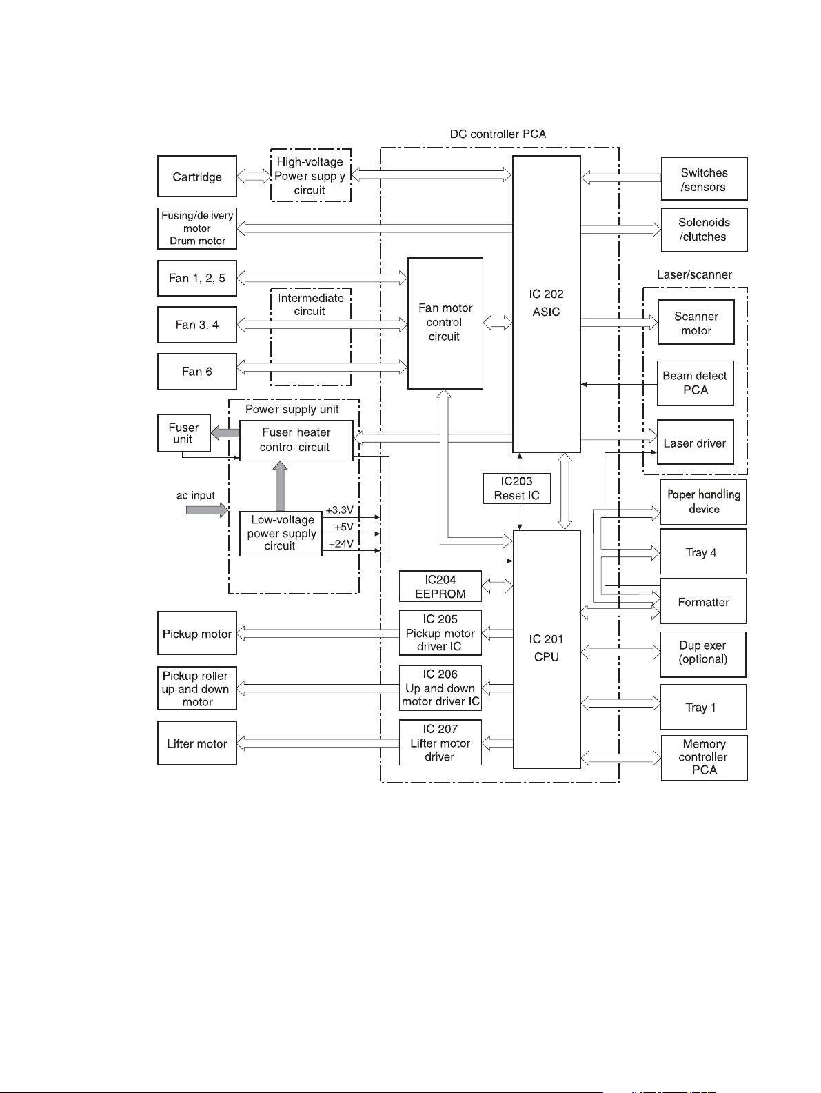
DC controller PCA
The DC controller circuit controls operational sequences of the printer.
Figure 25. DC controller PCA block diagram
76 Chapter 5 Theory of operation
Page 93

DC controller operations
z The CPU (IC201) on the DC controller PCA controls the following printer operations:
• Sequence of the printer
• Communications with the formatter
• High-voltage power supply circuit
• Rotation of the pickup motor, lifter motor, pic kup roller motor, and fan motor 6
• Communication with the duplexer and tray 1, if installed
• Fuser heater control circuit and fuser heater safety circuit
z The ASIC (IC202) on the DC controller PCA controls the following printer operations, according
to instructions from the CPU:
• laser/scanner
• rotation of fuser/delivery motor and drum motor
• sensors and switches
• clutches and solenoids
• rotation of fan motors 1 through 5
z The reset IC (IC203) monitors +3.3 V and resets the CPU and ASIC at power on.
z The EEPROM (IC204) stores backup data.
z The pickup motor driver IC (IC205) drives the pickup motor.
z The pickup roller up-and-down motor driver IC (IC206) drives the pickup roller up-and-down
motor.
z The lifter motor driver IC (IC207) drives the lifter motor.
z The fan motor control circuit turns fans on and off.
Engine control system 77
Page 94

High-voltage power supply circuit
The high-voltage power supply circuit applies a high-voltage bias to the primary charging roller, the
developing cylinder, the pre-transfer upper guide, the transfer charging roller, the separation static
charge eliminator, and the pressure roller through the ASIC (IC 202), according to instructions it
receives from the CPU (IC201) on the DC controller PCA. The high-voltage power supply circuit also
detects the toner level.
Figure 26. High-voltage power supply block diagram
78 Chapter 5 Theory of operation
Page 95

Each of the bias generation circuits has a specific purpose:
z Primary charging bias generation. Applies bias to the primary charging roller to spread a
uniform, negative charge on the photosensitive drum.
z Developing bias generation. Controls the amount of toner transferred onto latent images
formed on the photosensitive drum.
z Pre-transfer upper guide bias generation. Prevents toner on the photosensitive drum from
adhering to the pre-transfer upper guide.
z T ransfer bias generation. Each of the three types of transfer bias (cleaning bias, between-page
bias, and print bias) is applied to the transfer charging roller at specified intervals.
z Cleaning bias. Cleans the transfer charging roller by moving toner to the photosensitive drum.
z Between-page bias. Prevents residual toner on the photosensitive drum from adhering to the
transfer charging roller between pages of a multi-page print job.
z Print bias. Transfers toner from the photosensitive drum to the print media.
z Separation static charge eliminating bias. Stabilizes media delivery.
z Pressure roller bias generation. Prevents toner from adhering to the fuser roller.
z Toner level detection. Monitors toner level through two antennae (plate antenna and flat
antenna) in the print cartridge.
Engine control system 79
Page 96

Low-voltage power supply unit
The low-voltage power supply unit consists of the fuser control circuit and the low-voltage powersupply circuit.
Figure 27. Power-supply-block diagram
Fuser control circuit
Three heaters heat the fuser roller and pressure roller. The main heater (H1) heats the center of the
fuser roller, the sub-heater (H2) heats both ends of the fuser roller, and the lower heater (H3) heats
the pressure roller.
Two thermistors monitor the surface temperature of the rollers. The upper thermistor (TH1) monitors
the fuser roller surface temperature and the lower thermistor (TH2) monitors the pressure roller
surface temperature.
Two thermal switches guard against overheating the three heaters by turning off power to the heaters
when the temperature rises abnormally.
The printer is designed to prevent flicker. Lights attached to the same ac power source as the printer
can flicker as a result of high-frequency noise. To control flicker, the printer gradually increases and
decreases power to the heaters when they are turned on and off.
Low-voltage power-supply circuit
The low-voltage power-supply circuit converts ac voltage from the power source to dc voltage when
the printer is turned on. The ac power is converted as follows:
z +24 Vdc for motors, solenoids, clutches, and the high-voltage power supply circuit
z +5 Vdc for the laser/scanner PCA, the beam detect PCA, and the formatter
z +3.3 Vdc for the formatter, sensors, and the ICs on the DC controller PCA
80 Chapter 5 Theory of operation
Page 97

Formatter system
The formatter and DC controller exchange signals that allow the DC controller to begin the initial
rotation period (INTR), turn on the registration roller drive clutch, and feed media into the printer.
When media is positioned for printing, the formatter sends information through the DC controller to
the laser/scanner, which then turns the laser diodes on and off. Laser beams that the laser diodes
emit are reflected by the laser/scanner mirror, scanning across the photosensitive drum to form a
latent image on the drum.
The formatter system is responsible for the following:
z Receiving and processing data from the various printer interfaces
z Monitoring control panel input and relaying printer status information (through the control panel
and the I/O)
z Developing and coordinating data placement and timing with the print engine
z Storing font information and macros
z Communicating with the host computer
The formatter receives data from the I/O and converts it into a dot image. The formatter then sends a
print signal to the engine controller assembly. The engine controller assembly synchronizes the
image-formation system with the paper-feed system, and signals the formatter to send the printimage data. The formatter sends the print-image data (dots) in the form of a video signal, and the
printing process begins.
Formatter hardware
The formatter system includes the following components:
z ROM—Stores the dot patterns of internal character sets (fonts), in addition to storing
microprocessor control programs.
z RAM—Stores printing and font information received from the host system, and can also serve to
temporarily store a full page of print-image data before the data is sent to the print engine.
Increasing the RAM increases graphic intense printing operations, but it will not increase the
I/O buffer space or cause the printer to print more pages per minute.
z NVRAM—Stores information about the I/O and print environment configuration. The printer
keeps the contents of NVRAM when the power is turned off or disconnected. (As in other HP
LaserJet printers, downloaded fonts and macros are saved in conventional RAM and are lost
when power is turned off.)
z Interfaces
• Parallel interface (HP LaserJet 9040/9050 only)—Receives incoming data through its IEEE1284 B interface connector. The IEEE-1284 B interface provides high-speed, two-way
communication between the printer and the host, letting the customer change printer settings
and monitor printer status from the host computer.
• Parallel interface (HP LaserJet 9000 only)—Receives incoming data through its IEEE1284 C interface connector. The IEEE-1284 C interface provides high-speed, two-way
communication between the printer and the host, letting the customer change printer settings
and monitor printer status from the host computer.
• EIO—Supports a wide range of print servers and other add-on devices through PCI-based
EIO slots. HP Jetdirect EIO cards provide high-speed communication for network printing over
Ethernet, Ethernet and LocalTalk, Token Ring, or Fast Ethernet networks.
z Flash memory card (HP LaserJet 9040/9050 only)—The formatter has three flash memory card
slots. One slot is dedicated to printer firmware. The printer supports Type 1 and Type 2 flash
memory. Unlike standard printer memory, flash memory cards can be used to permanently store
downloaded fonts, macros, and forms even when the printer is turned off.
Formatter system 81
Page 98

Note A flash memory card that is designed for use with a digital camera should not be inserted into the
printer. The printer does not support photo printing directly from a flash memory card. If you install a
camera-type flash memory card, a message asking if you want to reformat the flash memory card
appears on the control-panel display . If you choose to reformat the card, all data on the card will be lost.
z Real Time Clock (HP LaserJet 9040/9050 only)—The user sets the date and time when the
printer is turned on for the first time. This date and time is used for the Wake-up time feature. A
battery supplies power when the printer is turned off.
z HP Jetdirect Fast Ethernet embedded print server (HP LaserJet 9040/9050 only)—The
HP LaserJet 9040n/9050n and the HP LaserJet 9040dn/9050dn printers include an HP Jetdirect
Fast Ethernet embedded print server on the formatter. This functions like other Jetdirect EIO
products.
82 Chapter 5 Theory of operation
Page 99

Laser/scanner system
The laser/scanner unit of the HP LaserJet 9000 series printer and the HP LaserJet 9040/9050 series
printer contains two laser diodes in its laser unit. The printer employs the “twin-beam method,” which
scans two lines simultaneously.
Based on signals it receives from the DC controller and the formatter, the laser/scanner PCA causes
the two laser diodes to emit laser beams. The beams strike a six-sided mirror that rotates at a
constant speed. The beams reflect off the mirror, pass through a focusing lens and a reflective mirror,
and focus on the photosensitive drum.
The scanning mirror rotating at a constant speed allows the laser beams to scan across the drum at
a constant speed. Finally, a latent image is formed on the drum surface by constant-speed rotation of
the photosensitive drum and constant-speed scanning of the laser beams.
Figure 28. Laser/scanner system
Laser/scanner system 83
Page 100

Image formation system
The image formation system consists of the cartridge, transfer charging roller, and fuser.
When a print command is sent from the formatter, the engine controller drives the main motor to
rotate the photosensitive drum, primary charging roller, developing cylinder, transfer charging roller,
and pressure roller.
The primary charging roller applies a uniform negative charge to the photosensitive drum surface.
Laser beams, modulated by the signals from the formatter, focus on the photosensitive drum surface
to form a latent image on the photosensitive drum.
Toner on the developing cylinder develops the latent image formed on the photosensitive drum into a
visible image, which is transferred onto media by the transfer charging roller. The toner transferred is
changed to a permanent image by heat and pressure in the fuser. The cleaning blade scrapes
residual toner from the photosensitive drum, and the primary charging roller applies a uniform
negative charge to the photosensitive drum surface in preparation for the next latent image.
Figure 29. Image formation
The eight processes of image formation
1 Conditioning (primary charging)—Consists of the application of a uniform negative charge to
the surface of the drum with the primary charging roller located in the print cartridge. The primary
charging roller is made of conductive rubber. An ac bias is applied to the roller to erase any
residual charges from any previous image. A negative dc bias is applied by the charging roller to
create a uniform neg ative potential on the drum surface.
2 Writing (laser beam exposure)—Two laser diodes project laser beams onto a rotating scanning
mirror. As the mirror rotates, the beams reflect off the mirror, first through a set of focusing
lenses, then off a mirror, and finally through a slot in the top of the print cartridge, and onto the
photosensitive drum. The twin beams sweep the drum from left to right, discharging the negative
potential wherever the beams strike the surface. This creates a latent electrostatic image, which
later is developed into a visible image.
3 Developing—At this stage of the process, the latent electrostatic image is present on the drum.
The toner particles obtain a negative surface charge by rubbing against the developing cylinder
which is connected to a negative dc supply. The negatively charged toner is attracted to the
discharged (exposed, grounded) areas of the drum, and is repelled from the negatively charged
(unexposed) areas.
4 Pre-transfer—Applies bias to prevent toner on the photosensitive drum from adhering to the
pre-transfer upper guide.
84 Chapter 5 Theory of operation
 Loading...