

Page 1

Installation Guide, HP Integrity rx8640 and
HP 9000 rp8440 Servers
HP Part Number: AB297-9012A-en
Published: September 2007
Edition: Fourth Edition
Page 2

© Copyright 2007 Hewlett-Packard Development Company, L.P.
The information contained herein is subject to changewithoutnotice.The only warranties for HP products and services are set forth in the express
warranty statements accompanying such products and services. Nothing herein should be construed as constituting an additional warranty. HP
shall not be liable for technical or editorial errors or omissions contained herein. Intel, Pentium, Intel Inside, and the Intel Inside logo are trademarks
or registered trademarks of Intel Corporation or its subsidiaries in the United States and other countries.
Page 3

Table of Contents
About This Document.........................................................................................................9
Book Layout............................................................................................................................................9
Intended Audience.................................................................................................................................9
Typographic Conventions......................................................................................................................9
Publishing History................................................................................................................................10
Related Information..............................................................................................................................11
Typographic Conventions.....................................................................................................................12
HP Encourages Your Comments..........................................................................................................13
1 Server Overview...........................................................................................................15
Detailed Server Description..................................................................................................................15
Dimensions and Components.........................................................................................................16
Front Panel.......................................................................................................................................19
Front Panel Indicators and Controls..........................................................................................19
Enclosure Status LEDs...............................................................................................................19
Cell Board........................................................................................................................................19
PDH Riser Board........................................................................................................................20
Central Processor Units..............................................................................................................21
Memory Subsystem....................................................................................................................21
DIMMs .......................................................................................................................................22
Valid Memory Configurations...................................................................................................23
Cells and nPartitions........................................................................................................................24
Internal Disk Devices ......................................................................................................................24
System Backplane............................................................................................................................25
System Backplane to Cell Board Connectivity...........................................................................26
System Backplane to Core I/O Card Connectivity.....................................................................26
System Backplane to PCI-X/PCIe Backplane Connectivity........................................................26
Clocks and Reset........................................................................................................................26
PCI-X I/O Subsystem.......................................................................................................................26
PCI-X/PCIe I/O Backplane..........................................................................................................29
PCIe Slot Boot Paths...................................................................................................................30
Core I/O Card.............................................................................................................................31
Core I/O Boot Paths...............................................................................................................32
Mass Storage (Disk) Backplane..................................................................................................32
2 Installing the System.....................................................................................................35
Receiving and Inspecting the Server Cabinet.......................................................................................35
Unpacking the Server Cabinet.........................................................................................................35
Securing the Cabinet........................................................................................................................38
Standalone and To-Be-Racked Systems................................................................................................39
Rack-Mount System Installation.....................................................................................................39
Lifting the Server Cabinet Manually....................................................................................................40
Using the RonI Model 17000 SP 400 Lifting Device.............................................................................40
Installing the Wheel Kit........................................................................................................................42
Installing the Top and Side Covers.......................................................................................................47
Removing the Top Cover.................................................................................................................48
Installing the Top Cover..................................................................................................................49
Removing the Side Cover................................................................................................................49
Installing the Side Cover.................................................................................................................50
Table of Contents 3
Page 4

Installing the Power Distribution Unit.................................................................................................50
Installing Additional Cards and Storage..............................................................................................51
Installing an Additional Hard Disk Drive ......................................................................................51
Removable Media Drive Installation...............................................................................................52
PCI-X Card Cage Assembly I/O Cards............................................................................................52
Installing an Additional PCI-X I/O Card...................................................................................56
Installing a A6869B VGA/USB PCI Card in a Server......................................................................58
Troubleshooting the A6869B VGA/USB PCI Card..........................................................................59
No Console Display...................................................................................................................60
Reference URL............................................................................................................................60
System Console Selection......................................................................................................................60
VGA Consoles..................................................................................................................................61
Interface Differences Between Itanium-based Systems...................................................................61
Other Console Types.......................................................................................................................61
Additional Notes on Console Selection...........................................................................................61
Cabling and Powering On the Server...................................................................................................62
Checking the Voltage.......................................................................................................................62
Verifying the Voltage Range of the Recptacle............................................................................62
Verifying the Safety Ground (Single Power Source)..................................................................63
Verifying the Safety Ground (Dual Power Source)....................................................................64
Voltage Check (Additional Procedure)...........................................................................................65
Connecting AC Input Power...........................................................................................................66
Applying Power to the Server....................................................................................................69
Installing The Line Cord Anchor (rack mounted servers)..............................................................69
Four Cell Server Installation (rp8400, rp8420, rp8440, rx8620, rx8640)......................................69
MP Core I/O Connections................................................................................................................70
Setting Up the Customer Engineer Tool (PC) .................................................................................71
Setting CE Tool Parameters........................................................................................................71
Connecting the CE Tool to the Local RS-232 Port on the MP ....................................................72
Turning On Housekeeping Power and Logging In to the MP........................................................72
Configuring LAN Information for the MP......................................................................................74
Accessing the Management Processor via a Web Browser.............................................................76
Verifying the Presence of the Cell Boards.......................................................................................78
System Console Selection................................................................................................................78
VGA Consoles............................................................................................................................79
Interface Differences Between Itanium-based Systems.............................................................79
Other Console Types..................................................................................................................79
Additional Notes on Console Selection.....................................................................................80
Configuring AC Line Status............................................................................................................80
Booting the Server ...........................................................................................................................80
Selecting a Boot Partition Using the MP ...................................................................................81
Verifying the System Configuration Using the EFI Shell...........................................................82
Booting HP-UX Using the EFI Shell...........................................................................................82
Adding Processors with Instant Capacity ......................................................................................82
Installation Checklist.......................................................................................................................83
4 Table of Contents
Page 5

List of Figures
1-1 16-Socket Server Block Diagram...................................................................................................16
1-2 Server (Front View With Bezel).....................................................................................................17
1-3 Server (Front View Without Bezel)................................................................................................17
1-4 Server (Rear View).........................................................................................................................18
1-5 Front Panel LEDs and Power Switch.............................................................................................19
1-6 Cell Board......................................................................................................................................20
1-7 Socket Locations on Cell Board.....................................................................................................21
1-8 Memory Subsystem.......................................................................................................................22
1-9 DIMM Slot Layout.........................................................................................................................23
1-10 Internal Disks Locations................................................................................................................24
1-11 System Backplane Block Diagram.................................................................................................25
1-12 PCI-X/PCIe Board to Cell Board Block Diagram...........................................................................27
1-13 Mass Storage Block Diagram.........................................................................................................33
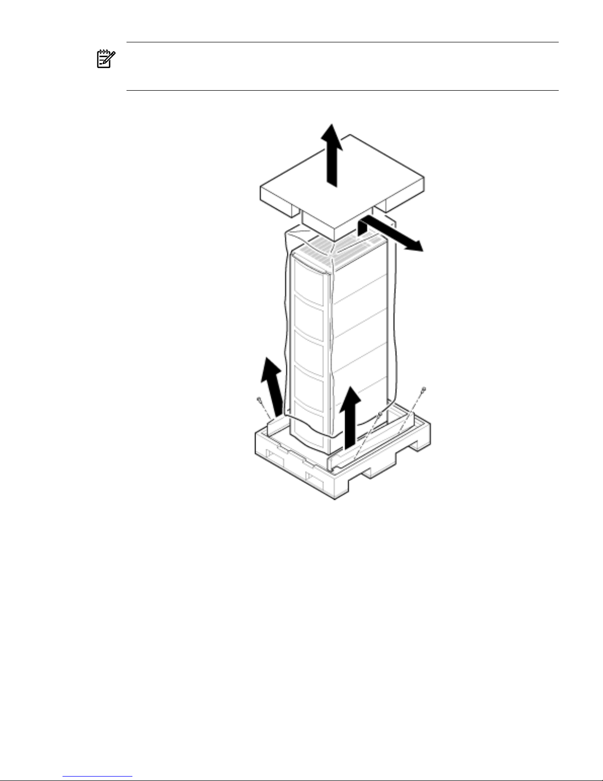
2-1 Removing the Polystraps and Cardboard.....................................................................................36
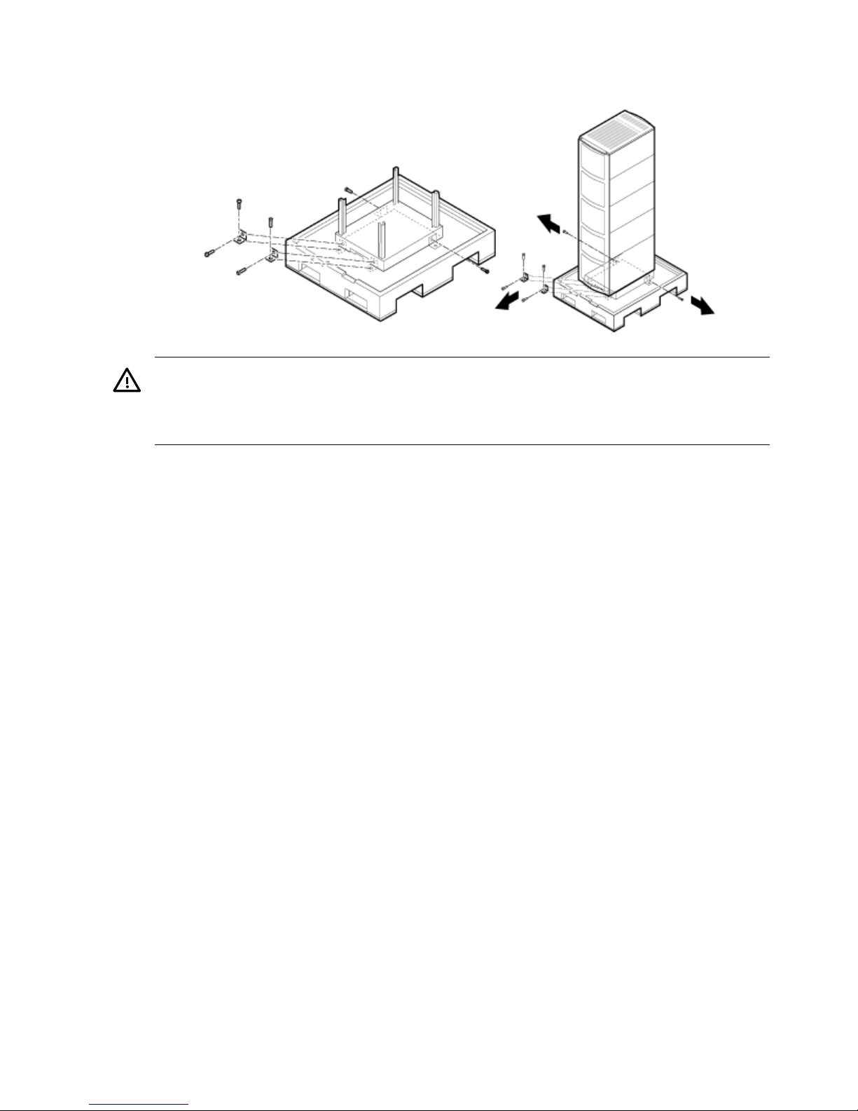
2-2 Removing the Shipping Bolts and Plastic Cover...........................................................................37
2-3 Preparing to Roll Off the Pallet.....................................................................................................38
2-4 Securing the Cabinet......................................................................................................................39
2-5 Positioning the Lifter to the Pallet.................................................................................................41
2-6 Raising the Server Off the Pallet Cushions....................................................................................42
2-7 Server on Shipping Pallet..............................................................................................................43
2-8 Removing Cushion from Front Edge of Server.............................................................................44
2-9 Attaching a Caster Wheel to the Server........................................................................................44
2-10 Attaching the Ramp to the Pallet..................................................................................................45
2-11 Removing Side Cushion from Server............................................................................................46
2-12 Securing Each Caster Cover to the Server.....................................................................................46
2-13 Completed Wheel Kit Installation.................................................................................................47
2-14 Cover Locations ............................................................................................................................48
2-15 Top Cover Detail ...........................................................................................................................49
2-16 Side Cover Detail...........................................................................................................................50
2-17 Disk Drive Location.......................................................................................................................51
2-18 Removable Media Drive Location.................................................................................................52
2-19 PCI I/O Slot Details........................................................................................................................58
2-20 PCI/PCI-X Card Location..............................................................................................................59
2-21 Console Output Device menu.......................................................................................................61
2-22 Voltage Reference Points for IEC-320 C19 Plug............................................................................62
2-23 Safety Ground Reference Check — Single Power Source.............................................................63
2-24 Safety Ground Reference Check — Dual Power Source...............................................................64
2-25 Wall Receptacle Pinouts................................................................................................................66
2-26 AC Power Input Labeling..............................................................................................................67
2-27 Distribution of Input Power for Each Bulk Power Supply............................................................68
2-28 Four Cell Line Cord Anchor (rp8400, rp8420, rp8440, rx8620, rx8640).........................................70
2-29 Line Cord Anchor and Velcro straps.............................................................................................70
2-30 LAN and RS-232 Connectors on the Core I/O Board ...................................................................72
2-31 Front Panel Display ......................................................................................................................73
2-32 BPS LED Location..........................................................................................................................73
2-33 MP Main Menu..............................................................................................................................74
2-34 The lc Command Screen................................................................................................................75
2-35 The ls Command Screen................................................................................................................76
2-36 Example sa Command..................................................................................................................77
2-37 Browser Window...........................................................................................................................77
2-38 The du Command Screen..............................................................................................................78
5
Page 6

2-39 Console Output Device menu.......................................................................................................79
2-40 The pwrgrd Command Screen.....................................................................................................80
6 List of Figures
Page 7

List of Tables
1-1 Cell Board CPU Module Load Order............................................................................................21
1-2 DIMM Sizes Supported.................................................................................................................22
1-3 DIMM Load Order........................................................................................................................23
1-4 Removable Media Drive Path........................................................................................................25
1-5 Hard Disk Drive Path....................................................................................................................25
1-6 PCI-X Slot Boot Paths Cell 0..........................................................................................................27
1-7 PCI-X Slot Boot Paths Cell 1..........................................................................................................27
1-8 PCI-X Slot Types............................................................................................................................29
1-9 PCIe Slot Types..............................................................................................................................31
1-10 Core I/O Boot Paths.......................................................................................................................32
2-1 Wheel Kit Packing List..................................................................................................................42
2-2 HP Integrity rx8640 Server PCI-X/PCIe I/O Cards........................................................................53
2-3 HP 9000 rp8440 Server PCI-X I/O Cards.......................................................................................54
2-4 Single Phase Voltage Examples.....................................................................................................63
2-5 BPS-to-Cell Board Configuration to Achieve N+1........................................................................69
2-6 Factory-Integrated Installation Checklist......................................................................................83
7
Page 8

8
Page 9

About This Document
This document covers the HP Integrity rx8640 and the HP 9000 rp8440 server systems.
This document does not describe system software or partition configuration in any detail. For
detailed information concerning those topics, refer to the HP System Partitions Guide:
Administration for nPartitions.
Book Layout
This document contains the following chapters:
• Chapter 1 - Server Overview
• Chapter 2 - Installing the System
Intended Audience
This document is intended to be used by customer engineers assigned to support the HP Integrity
rx8640 and HP 9000 rp8440 servers.
Typographic Conventions
This document uses the following typographical conventions:
%, $, or #
A percent sign represents the C shell system prompt. A dollar
sign represents the system prompt for the Bourne, Korn, and
POSIX shells. A number sign represents the superuser prompt.
audit(5) A manpage. The manpage name is audit, and it is located in
Section 5.
Command
A command name or qualified command phrase.
Computer output
Text displayed by the computer.
Ctrl+x A key sequence. A sequence such as Ctrl+x indicates that you
must hold down the key labeled Ctrl while you press another
key or mouse button.
ENVIRONMENT VARIABLE The name of an environment variable, for example, PATH.
[ERROR NAME]
The name of an error, usually returned in the errno variable.
Key The name of a keyboard key. Return and Enter both refer to the
same key.
Term The defined use of an important word or phrase.
User input
Commands and other text that you type.
Variable
The name of a placeholder in a command, function, or other
syntax display that you replace with an actual value.
[] The contents are optional in syntax. If the contents are a list
separated by |, you must choose one of the items.
{} The contents are required in syntax. If the contents are a list
separated by |, you must choose one of the items.
... The preceding element can be repeated an arbitrary number of
times.
Indicates the continuation of a code example.
| Separates items in a list of choices.
WARNING A warning calls attention to important information that if not
understood or followed will result in personal injury or
nonrecoverable system problems.
Book Layout 9
Page 10

CAUTION A caution calls attention to important information that if not
understood or followed will result in data loss, data corruption,
or damage to hardware or software.
IMPORTANT This alert provides essential information to explain a concept or
to complete a task
NOTE A note contains additional information to emphasize or
supplement important points of the main text.
Publishing History
The document printing date and part number indicate the document’s current edition. The
printing date will change when a new edition is printed. Minor changes may be made at reprint
without changing the printing date. The document part number will change when extensive
changes are made. Document updates may be issued between editions to correct errors or
document product changes. To ensure that you receive the updated or new editions, you should
subscribe to the appropriate product support service. See your HP sales representative for details.
You can find the latest version of this document on line at:
http://www.docs.hp.com.
March 2006. . . . . . . . . . . . . . . . . . . . . . . . . . . . . . . . . . . . . . . . . . . . . . . . . . . . . . . .First Edition
September 2006. . . . . . . . . . . . . . . . . . . . . . . . . . . . . . . . . . . . . . . . . . . . . . . . . . . . . . . .Second Edition
January 2007. . . . . . . . . . . . . . . . . . . . . . . . . . . . . . . . . . . . . . . . . . . . . . . . . . . . . . . .Third Edition
September 2007. . . . . . . . . . . . . . . . . . . . . . . . . . . . . . . . . . . . . . . . . . . . . . . . . . . . . . . .Fourth Edition
10
Page 11
Related Information
You can access other information on HP server hardware management, Microsoft® Windows®
administratuon, and diagnostic support tools at the following web sites:
http://docs.hp.com The main web site for HP technical documentation is http://docs.hp.com.
Server Hardware Information: http://docs.hp.com/hpux/hw/ The
http://docs.hp.com/hpux/hw/ web site is the systems hardware portion of docs.hp.com.
It provides HP nPartition server hardware management information, including site preparation,
installation, and more.
Related Information 11
Page 12
Windows Operating System Information You can find information about administration of the
Microsoft® Windows® operating system at the following web sites, among others:
• http://docs.hp.com/windows_nt/
• http://www.microsoft.com/technet/ HP books are available worldwide through
bookstores, online booksellers, and office and computer stores.
Diagnostics and Event Monitoring: Hardware Support Tools Complete information about HP
hardware support tools, including online and offline diagnostics and event monitoring tools, is
at the http://docs.hp.com/hpux/diag/ web site. This site has manuals, tutorials, FAQs,
and other reference material.
Web Site for HP Technical Support: http://us-support2.external.hp.com HP IT resource center
web site at http://us-support2.external.hp.com/ provides comprehensive support
information for IT professionals on a wide variety of topics, including software, hardware, and
networking.
Books about HP-UX Published by Prentice Hall The http://www.hp.com/hpbooks/ web
site lists the HP books that Prentice Hall currently publishes, such as HP-UX books including:
• HP-UX 11i System Administration Handbook and Toolkit
http://www.hp.com/hpbooks/prentice/ptr_0130600814.html
• HP-UX Virtual Partitions
http://www.hp.com/hpbooks/prentice/ptr_0130352128.html
HP books are available worldwide through bookstores, online booksellers, and office and
computer stores.
Typographic Conventions
The following notational conventions are used in this publication.
WARNING! A warning lists requirements that you must meet to avoid personal injury.
CAUTION: A caution provides information required to avoid losing data or avoid losing system
functionality.
NOTE: A note highlights useful information such as restrictions, recommendations, or important
details about HP product features.
• Commands and options are represented using this font.
• Text that you type exactly as shown is represented using this font.
• Text to be replaced with text that you supply is represented using this font.
Example:
“Enter the ls -l filename command” means you must replace filename with your own text.
• Keyboard keys and graphical interface items (such as buttons, tabs, and menu items)
are represented using this font.
Examples:
The Control key, the OK button, the General tab, the Options menu.
• Menu —> Submenu represents a menu selection you can perform.
Example:
“Select the Partition —> Create Partition action” means you must select the Create Partition
menu item from the Partition menu.
• Example screen output is represented using this font.
12
Page 13

HP Encourages Your Comments
HP encourages your comments concerning this document. We are committed to providing
documentation that meets your needs. Send any errors found, suggestions for improvement, or
compliments to:
Include the document title, manufacturing part number, and any comment, error found, or
suggestion for improvement you have concerning this document.
HP Encourages Your Comments 13
Page 14

14
Page 15

1 Server Overview
The HP Integrity rx8640 server and the HP 9000 rp8440 server are members of the HP
business-critical computing platform family of mid-range, mid-volume servers, positioned
between the HP Integrity rx7640, HP 9000 rp7440 and HP Integrity Superdome servers.
IMPORTANT: Ensure a valid UUID is either in place or available prior to maintenance of these
servers. This step is vital when performing upgrades and is recommended for existing hardware
service restoration. Specific information for upgrades is found in the Upgrade Guide, Mid-Range
Four-Cell HP Servers to HP Integrity rx8640, HP 9000 rp8440 Servers, located at the following URL:
http://docs.fc.hp.com.
The server is a 17U1high, 16-socket symmetric multiprocessor (SMP) rack-mount or standalone
server. Features of the server include:
• Up to 512 GB of physical memory provided by dual inline memory modules (DIMMs).
• Up to 32 processors with a maximum of 4 processor modules per cell board and a maximum
of 4 cell boards. Supports dual-core processors.
• One cell controller (CC) per cell board.
• Turbo fans to cool CPUs and CCs on the cell boards.
• Up to four embedded hard disk drives.
• Up to two internal DVD drives or one DVD drive and one DDS-4 DAT drive.
• Nine front chassis mounted N+1 fans.
• Twelve rear chassis mounted N+1 fans.
• Six N+1 PCI-X card cage fans.
• Up to six N+1 bulk power supplies.
• Two N+1 PCI-X power supplies.
• N+1 hot-swappable system clock oscillators.
• Sixteen PCI-X slots are divided into two I/O chassis. Each I/O chassis can accommodate up
to eight PCI/PCI-X/PCIe/PCI-X 2.0 cards.
• Up to two core I/O cards.
• One failover service processor per core I/O card.
• Four 220 V AC power plugs. Two are required and the other two provide power source
redundancy.
Detailed Server Description
The following section provides detailed intormation about the server components.
1. The U is a unit of measurement specifying product height. One U is equal to 1.75 inches.
Detailed Server Description 15
Page 16
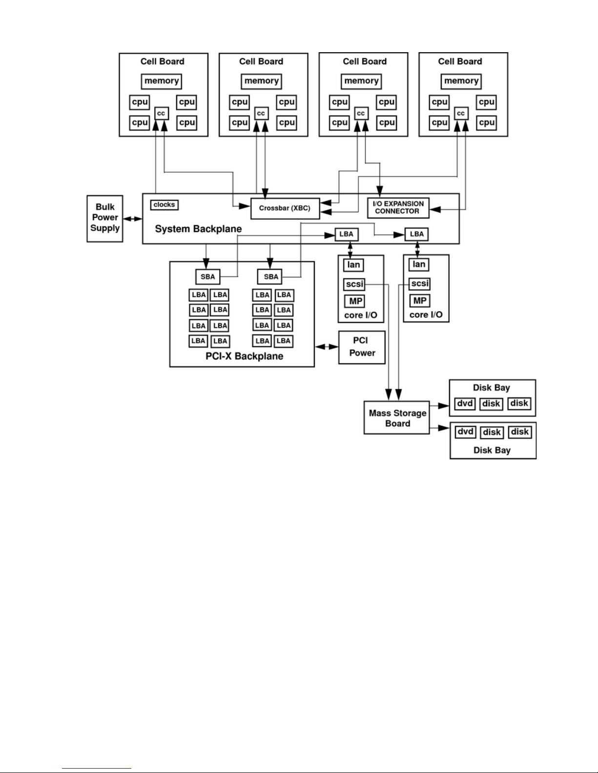
Figure 1-1 16-Socket Server Block Diagram
Dimensions and Components
The following section describes server dimensions and components.
16 Server Overview
Page 17
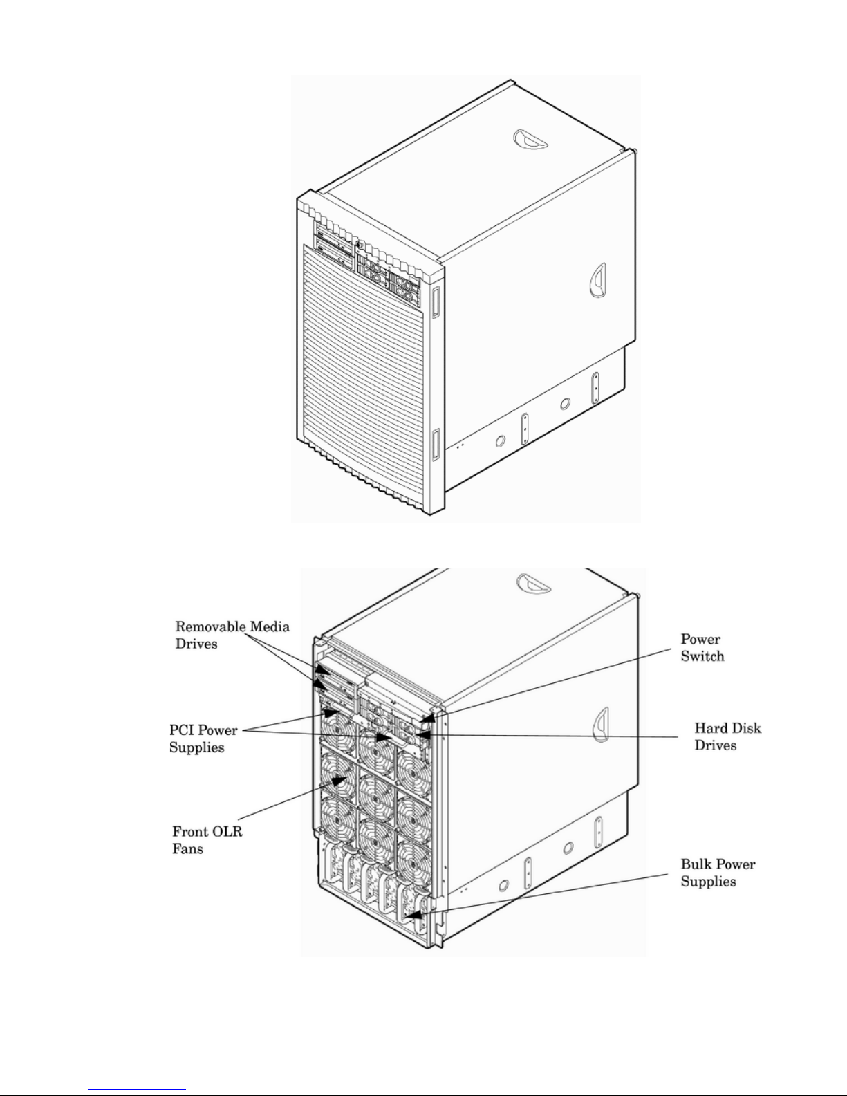
Figure 1-2 Server (Front View With Bezel)
Figure 1-3 Server (Front View Without Bezel)
The server has the following dimensions:
• Depth: Defined by cable management constraints to fit into a standard 36-inch deep rack:
25.5 inches from front rack column to PCI connector surface
Detailed Server Description 17
Page 18
26.7 inches from front rack column to core I/O card connector surface
30 inches overall package dimension, including 2.7 inches protruding in front of the front
rack columns
• Width: 17.5 inches, constrained by EIA standard 19-inch racks
• Height: 17 U (29.55 inches), constrained by package density
The mass storage section located in the front enables access to removable media drives without
removal of the bezel. The mass storage bay accommodates two 5.25-inch removable media drives
and up to four 3.5-inch hard disk drives. The front panel display, containing LEDs and the system
power switch, is located directly above the hard drive media bays.
Below the mass storage section and behind a removable bezel are two PCI-X power supplies.
Each PCI-X power supply powers both I/O partitions. Two PCI-X power supplies offer a N+1
configuration.
Enclosed with protective finger guards are nine front online replace (OLR) fan modules.
The bulk power supply is partitioned by a sealed metallic enclosure located in the bottom of the
server. This enclosure houses the N+1 fully redundant bulk power supplies. Install these power
supplies from the front of the server after removing the front bezel. The power supply is 2.45 X
5.625 X 20.0 inches.
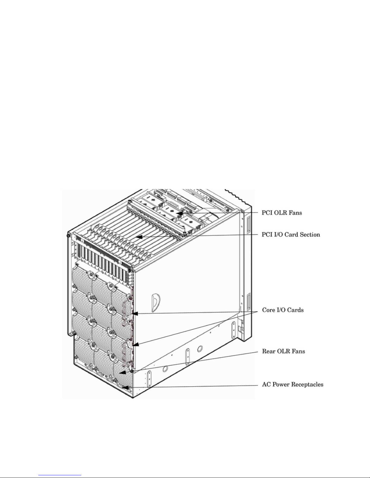
Figure 1-4 Server (Rear View)
Access the PCI-X/PCIe I/O card section, located toward the rear by removing the top cover.
The PCI card bulkhead connectors are located at the rear top.
The PCI-X OLR fan modules are located in front of the PCI cards. They are housed in plastic
carriers.
The 12 rear OLR fans attached outside the chassis house 120-mm exhaust fans.
18 Server Overview
Page 19
The cell boards are located on the right side of the server behind a removable side cover. For
rack mounted servers on slides, the rack front door requires removal if it is hinged on the right
side of the rack. Removal will allow unrestricted access to server sides after sliding server out
for service..
The two redundant core I/O cards are positioned vertically end-to-end at the rear of the chassis.
Redundant line cords attach to the AC power receptacles at the bottom rear. Two 20-amp cords
are required to power the server. Two additional line cords provide redundancy.
Access the system backplane by removing the left side cover. The system backplane hinges from
the lower edge and is anchored at the top with a single large jack screw assembly.
The SCSI ribbon cable assembly also routes across and fastens to the backside of the system
backplane near the connectors that attach the core I/O boards.
The blue deployment handles hinge outward for manual lift. When server is slide mounted, they
retract against chassis to enable slide action without obstruction.
Front Panel
Front Panel Indicators and Controls
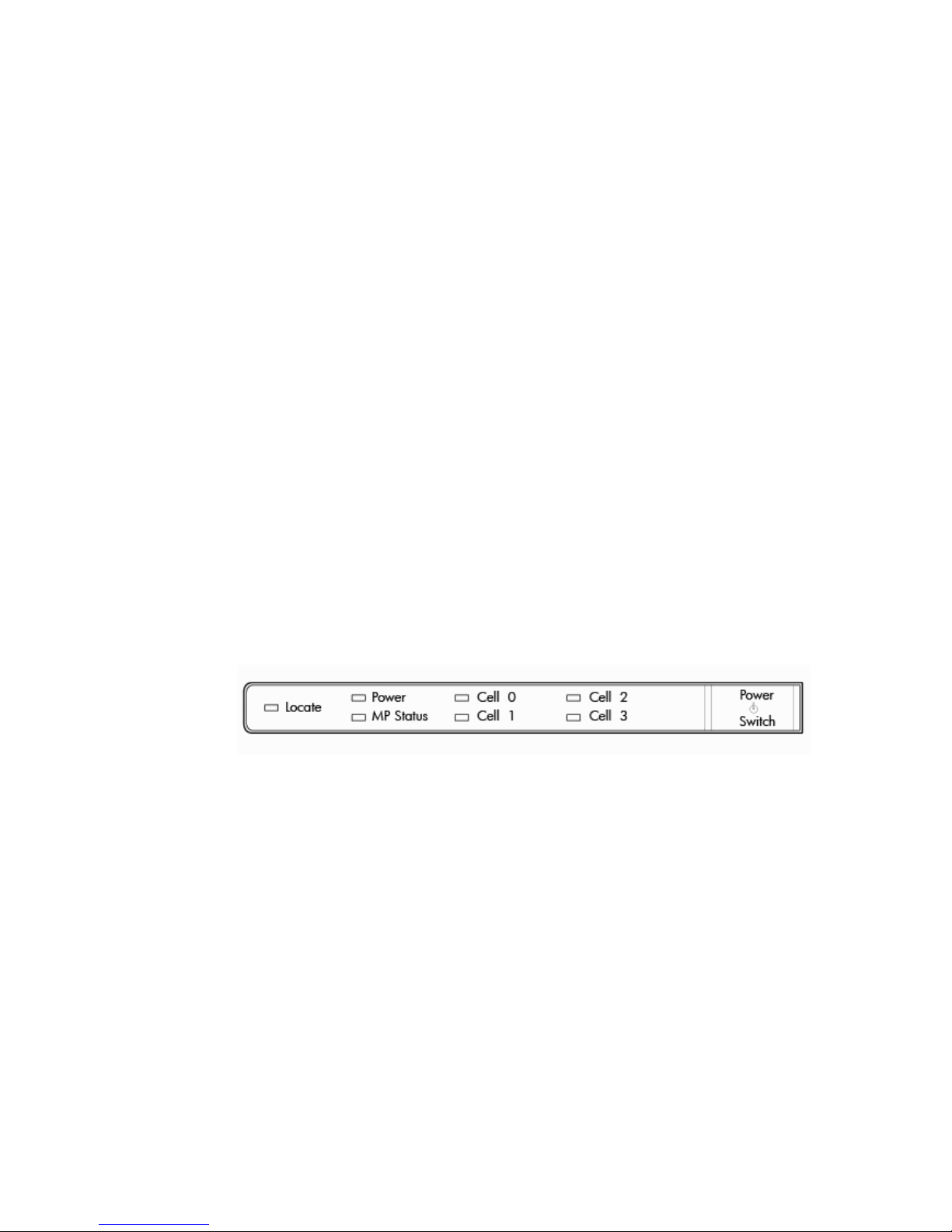
The front panel, located on the front of the server, includes the power switch. Refer to Figure 1-5.
Enclosure Status LEDs
The following status LEDs are on the front panel:
• Locate LED (blue)
• Power LED (tricolor)
• Management processor (MP) status LED (tricolor)
• Cell 0, 1, 2, 3 status (tricolor) LEDs
Figure 1-5 Front Panel LEDs and Power Switch
Cell Board
The cell board, illustrated in Figure 1-6, contains the processors, main memory, and the CC
application specific integrated circuit (ASIC) which interfaces the processors and memory with
the I/O. The CC is the heart of the cell board, providing a crossbar connection that enables
communication with other cell boards in the system. It connects to the processor dependent
hardware (PDH) and microcontroller hardware. Each cell board holds up to four processor
modules and 16 memory DIMMs. One to four cell boards can be installed in the server. A cell
board can be selectively powered off for adding processors, memory or maintenance of the cell
board, without affecting cells in other configured partitions.
Detailed Server Description 19
Page 20
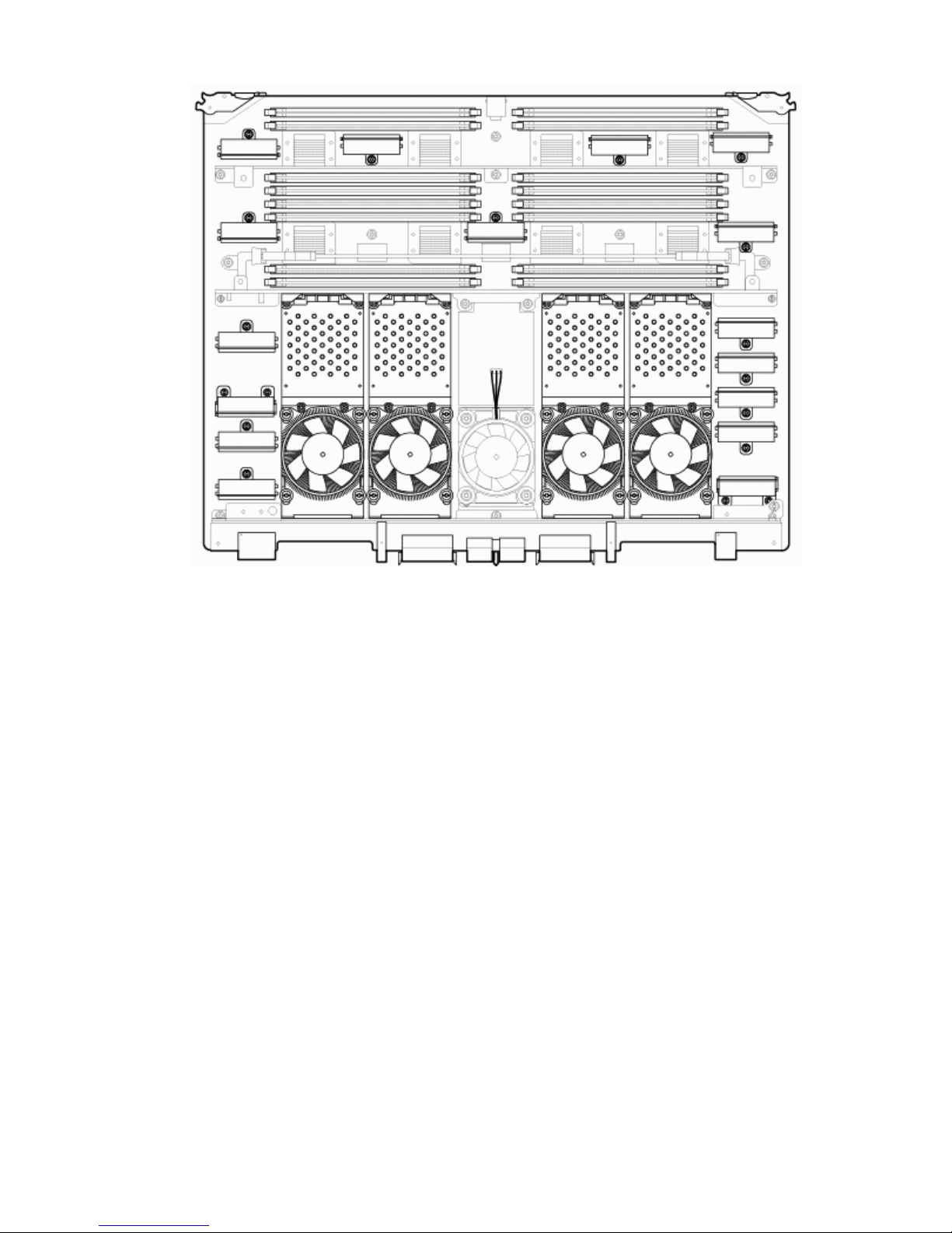
Figure 1-6 Cell Board
The server has a 48 V distributed power system and receives the 48 V power from the system
backplane board. The cell board contains DC-to-DC converters to generate the required voltage
rails. The DC-to-DC converters on the cell board do not provide N+1 redundancy.
The cell board contains the following major buses:
• Front side buses (FSB) for each of the four processors
• Four memory buses (one going to each memory quad)
• Incoming and outgoing I/O bus that goes off board to an SBA chip
• Incoming and outgoing crossbar busses that communicate to the crossbar chips on the system
backplane
• PDH bus that goes to the PDH and microcontroller circuitry
All of these buses come together at the CC chip.
Because of space limitations on the cell board, the PDH and microcontroller circuitry reside on
a riser board that plugs at a right angle into the cell board. The cell board also includes clock
circuits, test circuits, and decoupling capacitors.
PDH Riser Board
The server PDH riser board is a small card that plugs into the cell board at a right angle. The
PDH riser interface contains the following components:
• Microprocessor memory interface microcircuit
• Hardware including the processor dependant code (PDH) flash memory
• Manageability microcontroller with associated circuitry
The PDH obtains cell board configuration information from cell board signals and from the cell
board local power module (LPM).
20 Server Overview
Page 21
Central Processor Units
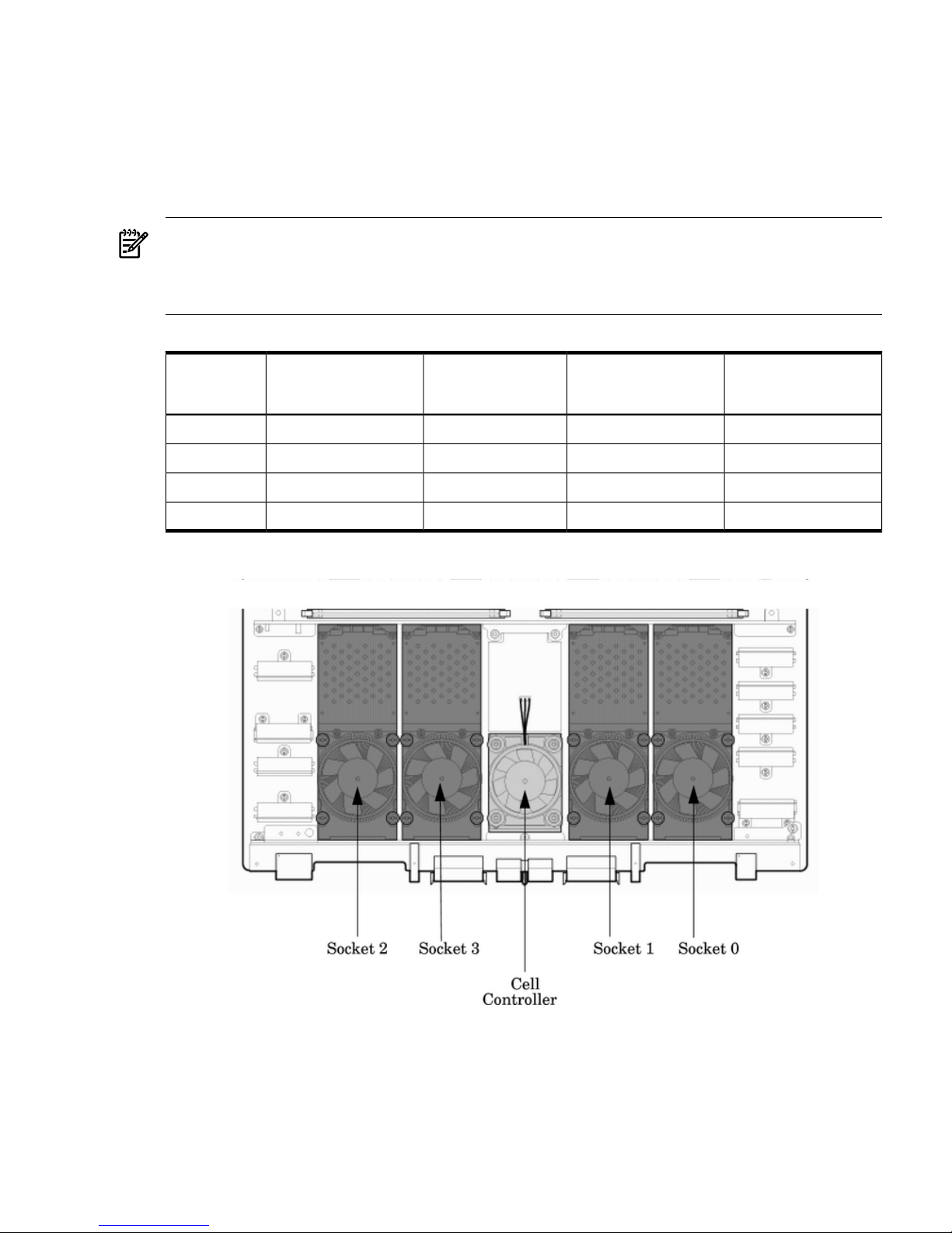
The cell board can hold up to four CPU modules. Each CPU module can contain up to two CPU
cores on a single die. Modules are populated in increments of one. On a cell board, the processor
modules must be the same family, type, and clock frequencies. Mixing of different processors
on a cell or a partition is not supported. See Table 1-1 for the load order that must be maintained
when adding processor modules to the cell board. See Figure 1-7 for the locations on the cell
board for installing processor modules.
NOTE: Unlike previous HP cell based systems, the server cell board does not require that a
termination module be installed at the end of an unused FSB. System firmware is allowed to
disable an unused FSB in the CC. This enables both sockets of the unused bus to remain
unpopulated.
Table 1-1 Cell Board CPU Module Load Order
Socket 0Socket 1Socket 3Socket 2Number of
CPU Modules
Installed
CPU installedEmpty slotEmpty slotEmpty slot1
CPU installedEmpty slotEmpty slotCPU installed2
CPU installedCPU installedEmpty slotCPU installed3
CPU installedCPU installedCPU installedCPU installed4
Figure 1-7 Socket Locations on Cell Board
Memory Subsystem
Figure 1-8 shows a simplified view of the memory subsystem. It consists of four independent
access paths, each path having its own address bus, control bus, data bus, and DIMMs . Address
and control signals are fanned out through register ports to the synchronous dynamic random
access memory (SDRAM) on the DIMMs.
Detailed Server Description 21
Page 22
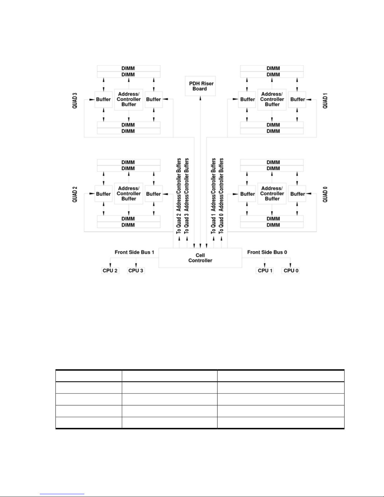
The memory subsystem comprises four independent quadrants. Each quadrant has its own
memory data bus connected from the cell controller to the two buffers for the memory quadrant.
Each quadrant also has two memory control buses: one for each buffer.
Figure 1-8 Memory Subsystem
DIMMs
The memory DIMMs used by the server are custom designed by HP. Each DIMM contains DDR-II
SDRAM memory that operates at 533 MT/s. Industry standard modules do not support the high
availability and shared memory features of the server. Therefore, industry standard DIMM
modules are not supported.
The server supports DIMMs with densities of 1, 2, 4, and 8 GB. Table 1-2 lists each supported
DIMM size, the resulting total server capacity, and the memory component density. Each DIMM
is connected to two buffer chips on the cell board.
Table 1-2 DIMM Sizes Supported
Memory Component DensityTotal CapacityDIMM Size
256 Mb64 GB1 GB
512 Mb128 GB2 GB
1024 Mb256 GB4 GB
2048 Mb512 GB8 GB
22 Server Overview
Page 23
Valid Memory Configurations
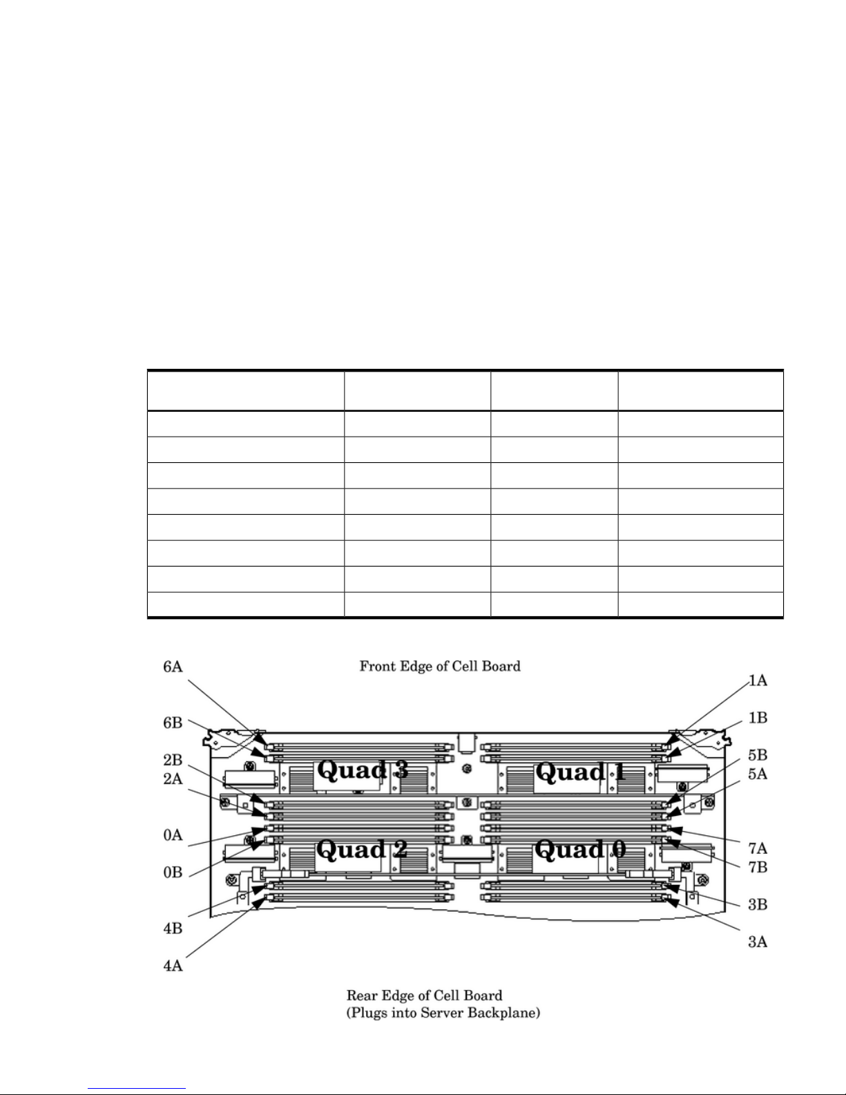
The first cell must have one DIMM pair loaded in slots 0A/0B. The server can support as little
as 2 GB of main memory using two 1 GB DIMMs installed on one of the cell boards and as much
as 512 GB by filling all 16 DIMM slots on all four cell boards with 8 GB DIMMs.
The following rules explain the memory configuration:
1. DIMMs must be loaded in pairs (same size within a pair).
2. DIMM pairs must be loaded in slot order (0A/0B, 1A/1B, 2A/2B, ...)
3. Largest DIMMs must be loaded first followed by progressively smaller DIMM module sizes.
A paired set of DIMMs is called a rank. DIMMs in a rank must be of the same capacity. See
Table 1-3 and Figure 1-9 for DIMM load order and layout on the cell board.
A quad is a grouping of four DIMMs (Figure 1-9). Configurations with 8 or 16 DIMM slots loaded
are recommended. Adding a rank enables a dedicated DDR-II bus on a cell to increase the amount
of usable memory bandwidth available. Available memory is proportional to the amount of
memory installed.
Table 1-3 DIMM Load Order
Quad LocationDIMM Location on Cell
Board
Action TakenNumber of DIMMs Installed
Quad 20A and 0BInstall first2 DIMMs = 1 rank
Quad 11A and 1BAdd second4 DIMMs = 2 rank
Quad 32A and 2BAdd third6 DIMMs = 3 rank
Quad 03A and 3BAdd fourth8 DIMMs = 4 rank
Quad 24A and 4BAdd fifth10 DIMMs = 5 rank
Quad 15A and 5BAdd sixth12 DIMMs = 6 rank
Quad 36A and 6BAdd seventh14 DIMMs = 7 rank
Quad 07A and 7BAdd last16 DIMMs = 8 rank
Figure 1-9 DIMM Slot Layout
Detailed Server Description 23
Page 24
Cells and nPartitions
An nPartition comprises one or more cells working as a single system. Any I/O chassis that is
attached to a cell belonging to an nPartition is also assigned to the nPartition. Each I/O chassis
has PCI card slots, I/O cards, attached devices, and a core I/O card assigned to the I/O chassis.
On the server, each nPartition has its own dedicated portion of the server hardware which can
run a single instance of the operating system. Each nPartition can boot, reboot, and operate
independently of any other nPartitions and hardware within the same server complex.
The server complex includes all hardware within an nPartition server: all cabinets, cells, I/O
chassis, I/O devices and racks, management and interconnecting hardware, power supplies, and
fans.
A server complex can contain one or more nPartitions, enabling the hardware to function as a
single system or as multiple systems.
NOTE: Partition configuration information is available on the Web at:
http://docs.hp.com.
Refer to HP System Partitions Guide: Administration for nPartitions for details.
Internal Disk Devices
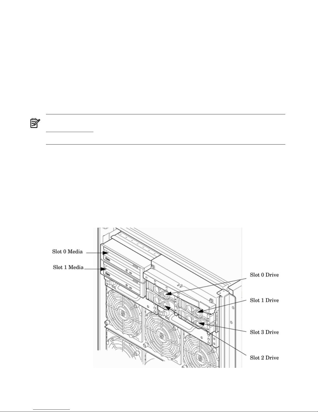
Figure 1-10 (page 24) shows the top internal disk drives connect to cell 0 through the core I/O
for cell 0, in a server cabinet. The bottom internal disk drives connect to cell 1 through the core
I/O for cell 1.
The upper removable media drive connects to cell 0 through the core I/O card for cell 0 and the
lower removable media drive connects to cell 1 through the core I/O card for cell 1.
A list of replacement disk drives for the server is in Appendix A. The list contains both removable
media disk drives and hard disk drives.
Figure 1-10 Internal Disks Locations
24 Server Overview
Page 25
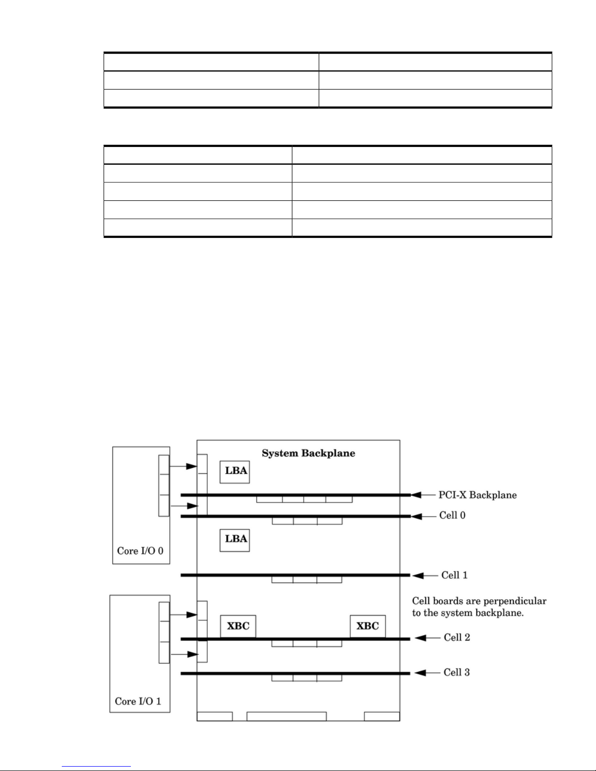
Table 1-4 Removable Media Drive Path
PathRemovable Media
0/0/0/2/1.x1.0Slot 0 media
1/0/0/2/1.x1.0Slot 1 media
1 X equals 2 for a DVD drive while X equals 3 for a DDS-4 DAT drive.
Table 1-5 Hard Disk Drive Path
PathHard Drive
0/0/0/2/0.6.0Slot 0 drive
0/0/0/3/0.6.0Slot 1 drive
1/0/0/2/0.6.0Slot 2 drive
1/0/0/3/0.6.0Slot 3 drive
System Backplane
The system backplane board contains the following components:
• Two crossbar chips (XBC)
• Clock generation logic
• Preset generation logic
• Power regulators
• Two local bus adapter (LBA) chips that create internal PCI buses for communicating with
the core I/O card.
The backplane also contains connectors for attaching the cell boards, PCI-X backplane, MP core
I/O cards SCSI cables, bulk power, chassis fans, front panel display, intrusion switches, and
external system bus adapters (SBA) link connectors.
Figure 1-11 System Backplane Block Diagram
Detailed Server Description 25
Page 26

The two LBA PCI bus controllers on the system backplane create the PCI bus for the core I/O
cards. You must shut down the partition for the core I/O card before removing the card.
Having the SCSI connectors on the system backplane allows replacement of the core I/O card
without having to remove cables in the process.
System Backplane to Cell Board Connectivity
The system backplane provides four sets of connectors, one set for each cell board.
The system backplane routes the signals from the cell boards to the communication crossbars.
Cell boards 0 and 1 are directly connected to the I/O backplane found in the server. Cell boards
2 and 3 can be connected to a separate I/O expansion chassis connected to the system backplane.
System Backplane to Core I/O Card Connectivity
The core I/O cards connect at the rear of the system backplane through two connectors. SCSI and
LAN on a core I/O are accessed via a PCI-X 66 MHz bus. Two LBA bus controllers located on
the system backplane allow communication to the I/O devices. The LBAs are connected to the
SBA on the PCI-X/PCIe backplane by single ropes.
The system backplane routes the signals to the various components in the system. The core I/O
signals include the SCSI bus for the system hard drives and the bus for the removable media
devices. Each core I/O card provides SCSI buses for the mass storage devices.
The management processor for the chassis resides on the core I/O card, so the system backplane
also provides interfaces required for management of the system. These interfaces and the
manageability circuitry run on standby power.
You can remove the core I/O cards from the system as long as you shut down the partition for
the core I/O card before removing the card. The hot-plug circuitry that enables this feature is
located on the system backplane near the core I/O sockets.
System Backplane to PCI-X/PCIe Backplane Connectivity
The PCI-X/PCIe backplane uses two connectors for the SBA link bus and two connectors for the
high-speed data signals and the manageability signals.
SBA link bus signals are routed through the system backplane to the cell controller on each
corresponding cell board.
The high-speed data signals are routed from the SBA chips on the PCI-X/PCIe backplane to the
two LBA PCI bus controllers on the system backplane.
Clocks and Reset
The system backplane contains reset and clock circuitry that propagates through the whole
system. The system backplane central clocks drive all major chip set clocks. The system central
clock circuitry features redundant, hot-swappable oscillators.
PCI-X I/O Subsystem
The cell board to the PCI-X board path runs from the CC to the SBA, from the SBA to the ropes,
from the ropes to the LBA, and from the LBA to the PCI slots as shown in Figure 1-12. The CC
on cell board 0 and cell board 1 communicates through an SBA over the SBA link. The SBA link
consists of both an inbound and an outbound link with a peak bandwidth of approximately 11.5
GB/s at 3.2 GT/s. The SBA converts the SBA link protocol into “ropes.” A rope is defined as a
high-speed, point-to-point data bus. The SBA can support up to 16 of these high-speed
bidirectional rope links for a total aggregate bandwidth of approximately 11.5 GB/s.
There are LBA chips on the PCI-X backplane that act as a bus bridge, supporting either one or
two ropes for PCI-X 133 MHz slots and the equivalent bandwidth of four ropes for PCI-X 266
slots. Each LBA acts as a bus bridge, supporting one or two ropes and capable of driving 33 MHz
or 66 MHz for PCI cards. The LBAs can also drive at 66 MHz or 133 MHz for PCI-X mode 1 cards,
26 Server Overview
Page 27
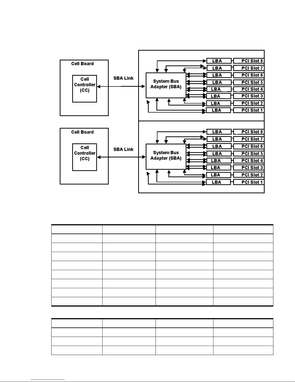
and at 266 MT/s for PCI-X mode 2 cards installed in mode 2 capable slots. When cell board 2 and
cell board 3 are present, the cell boards attach to their own associated SBA and LBA chips on the
PCI-X board in the Server Expansion Unit.
Figure 1-12 PCI-X/PCIe Board to Cell Board Block Diagram
Table 1-6 and Table 1-7 list the mapping of PCI-X slots to boot paths. The cell column refers to
the cell boards installed in the server.
Table 1-6 PCI-X Slot Boot Paths Cell 0
PathRopesPCI SlotCell
0/0/8/1/08/910
0/0/10/1/010/1120
0/0/12/1/012/1330
0/0/14/1/014/1540
0/0/6/1/06/750
0/0/4/1/04/560
0/0/2/1/02/370
0/0/1/1/0180
Table 1-7 PCI-X Slot Boot Paths Cell 1
PathRopesPCI SlotCell
1/0/8/1/08/911
1/0/10/1/010/1121
1/0/12/1/012/1331
Detailed Server Description 27
Page 28
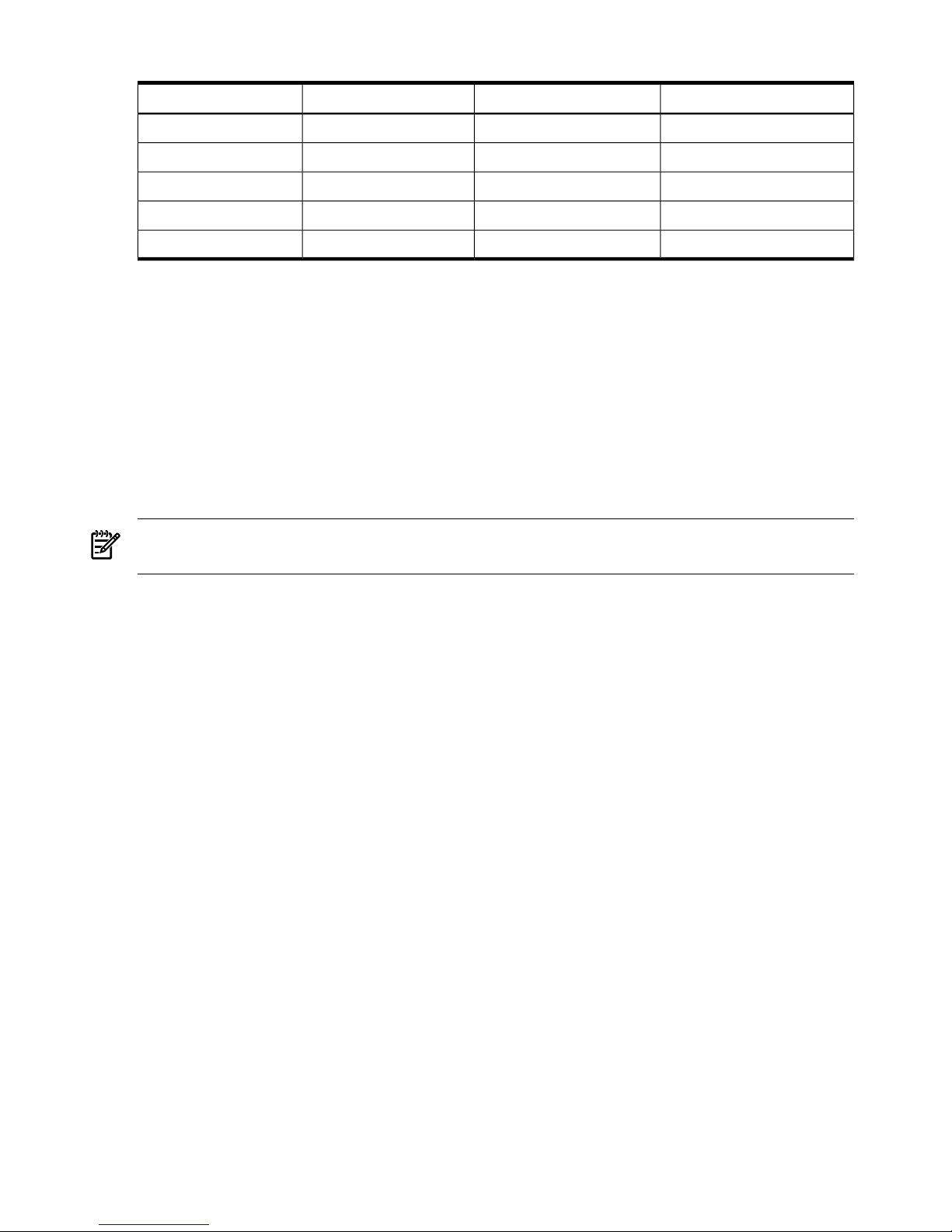
Table 1-7 PCI-X Slot Boot Paths Cell 1 (continued)
PathRopesPCI SlotCell
1/0/14/1/014/1541
1/0/6/1/06/751
1/0/4/1/04/561
1/0/2/1/02/371
1/0/1/1/0181
The server supports two internal SBAs. Each SBA provides the control and interfaces for eight
PCI-X slots. The interface is through the rope bus (16 ropes per SBA). For each SBA, the ropes
are divided in the following manner:
• A single rope is routed to support the core I/O boards through LBAs located on the system
backplane.
• A single rope is routed to an LBA on the PCI backplane to support a slot for PCI and PCI-X
cards (slot 8).
• Six ropes are bundled into double ropes to three (3) LBAs. They support slots 1, 2, and 7 for
PCI and PCI-X mode 1 cards.
• Eight fat ropes are bundled into quad ropes to four (4) LBAs. They support slots 3, 4, 5, and
6 for PCI and PCI-X mode 2 cards.
NOTE: PCI-X slots 1-7 are dual rope slots while slot 8 is a single rope slot. A rope is defined as
a high-speed, point-to-point data bus.
Each of the 16 slots is capable of 33 MHz/66 MHz PCI or 66 MHz/133 MHz PCI-X. Four slots in
PCI-X support 266 MHz. All 16 PCI slots are keyed for 3.3 V connectors (accepting both Universal
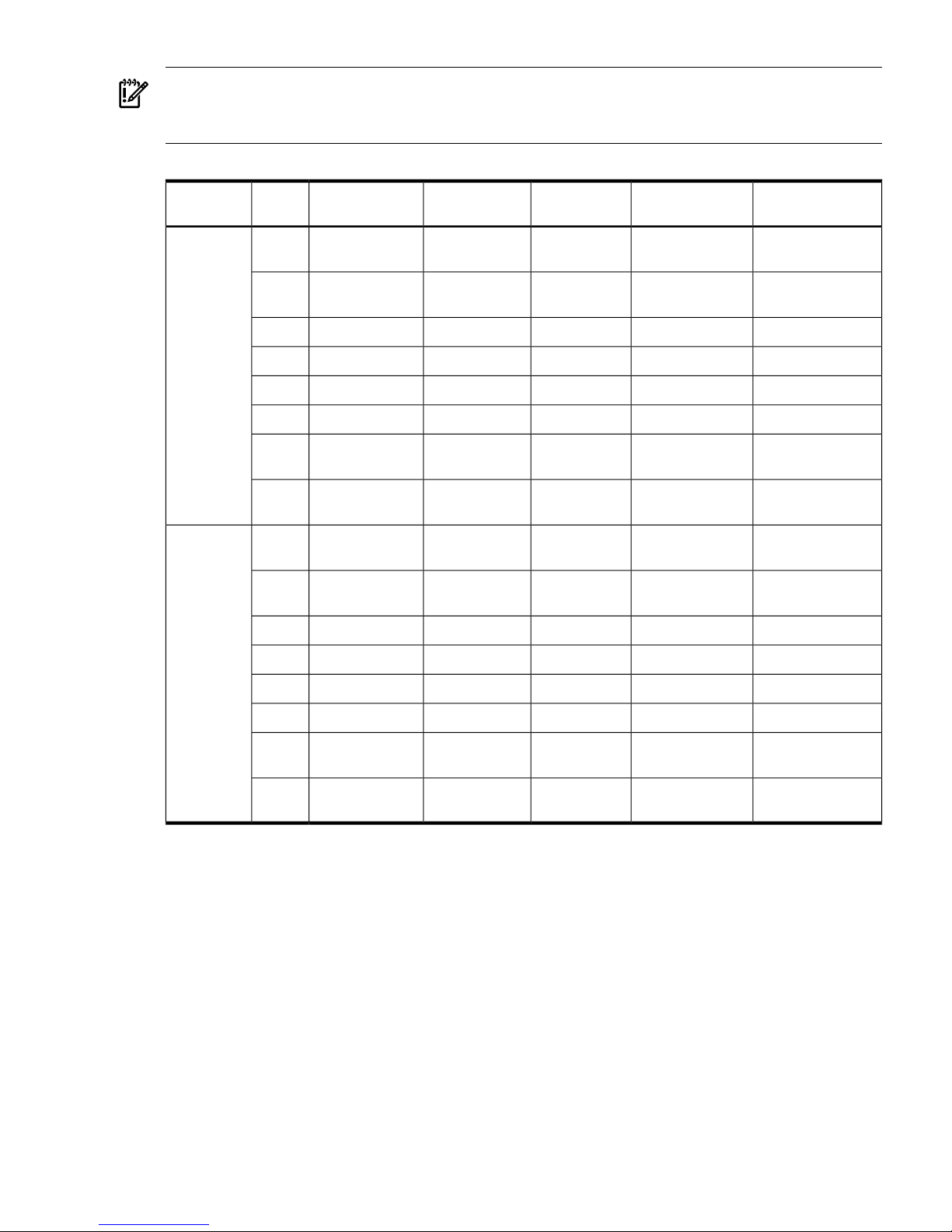
and 3.3 V cards). The PCI-X backplane does not provide any 5 V slots for the I/O cards. Table 1-8
summarizes the PCI-X slot types.
The PCI-X backplane is physically one board, yet it behaves like two independent partitions.
SBA 0 and its associated LBAs and eight PCI-X slots form one I/O partition. SBA 1 and its
associated LBAs and eight PCI-X slots form the other I/O partition. One I/O partition can be reset
separately from the other I/O partition but cannot be powered down independently.
28 Server Overview
Page 29
IMPORTANT: Always refer to the PCI card's manufacturer for the specific PCI card performance
specifications. PCI, PCI-X mode 1, and PCI-X mode 2 cards are supported at different clock
speeds. Select the appropriate PCI-X I/O slot for best performance.
Table 1-8 PCI-X Slot Types
PCI Mode SupportedSupported CardsRopesMaximum Peak
Bandwidth
Maximum MHzSlot
1
I/O Partition
PCI or PCI-X Mode
1
3.3 V001533 MB/s668
2
0
PCI or PCI-X Mode
1
3.3 V002/0031.06 GB/s1337
PCI-X Mode 23.3 V or 1.5 V004/0052.13 GB/s2666
PCI-X Mode 23.3 V or 1.5 V006/0072.13 GB/s2665
PCI-X Mode 23.3 V or 1.5 V014/0152.13 GB/s2664
PCI-X Mode 23.3 V or 1.5 V012/0132.13 GB/s2663
PCI or PCI-X Mode
1
3.3 V010/0111.06 GB/s1332
PCI or PCI-X Mode
1
3.3 V008/0091.06 GB/s1331
PCI or PCI-X Mode
1
3.3 V001533 MB/s668
2
1
PCI or PCI-X Mode
1
3.3 V002/0031.06 GB/s1337
PCI-X Mode 23.3 V or 1.5 V004/0052.13 GB/s2666
PCI-X Mode 23.3 V or 1.5 V006/0072.13 GB/s2665
PCI-X Mode 23.3 V or 1.5 V014/0152.13 GB/s2664
PCI-X Mode 23.3 V or 1.5 V012/0132.13 GB/s2663
PCI or PCI-X Mode
1
3.3 V010/0111.06 GB/s1332
PCI or PCI-X Mode
1
3.3 V008/0091.06 GB/s1331
1 Each slot will auto select the proper speed for the card installed up to the maximum speed for the slot. Placing high
speed cards into slow speed slots will cause the card to be driven at the slow speed.
2 Slot is driven by a single rope and has a maximum speed of 66 MHz.
PCI-X/PCIe I/O Backplane
The 16–slot (8 PCI and PCI-X; 8 PCI-Express) mixed PCI-X/PCI-Express (“PCIe”) I/O backplane
was introduced for the Dual-Core Intel® Itanium® processor 9100 Series release and is heavily
leveraged from the PCI-X backplane design. Only the differences will be descibed here. See
“PCI-X I/O Subsystem” (page 26) for common content between the two boards..
The PCI-X/PCIe I/O backplane comprises two logically independent I/O circuits (partitions) on
one physical board.
• The I/O chip in cell location zero (0) and its associated four PCI-X ASICs, four PCIe ASICs,
and their respective PCI/PCI-X/PCIe slots form PCI-Express I/O partition 0 plus core I/O.
• The I/O chip in cell location one (1) and its associated four PCI-X ASICs, four PCIe ASICs,
and their respective PCI/PCI-X/PCIe slots form PCI-Express I/O partition 1 plus core I/O.
Detailed Server Description 29
Page 30

Each PCI/PCI-X slot has a host-to-PCI bridge associated with it, and each PCIe slot has a
host-to-PCIe bridge associated with it. A dual slot hot swap controller chip and related logic is
also associated with each pair of PCI or PCIe slots. The I/O chip on either cell location 0 or 1 is a
primary I/O system interface. Upstream, the I/O chips communicate directly with the cell controller
ASIC on the host cell board via a high bandwidth logical connection known as the HSS link.When
installed in the SEU chassis within a fully configured system, the ASIC on cell location 0 connects
to the cell controller chip on cell board 2, and the ASIC on cell location 1 connects to the cell
controller chip on cell board 3 through external link cables.
Downstream, the ASIC spawns 16 logical 'ropes' that communicate with the core I/O bridge on
the system backplane, PCI interface chips, and PCIe interface chips. Each PCI chip produces a
single 64–bit PCI-X bus supporting a single PCI or PCI-X add-in card. Each PCIe chip produces
a single x8 PCI-Express bus supporting a single PCIe add-in card.
The ropes in each I/O partition are distributed as follows:
• One PCI-X ASIC is connected to each I/O chip with a single rope capable of peak data rates
of 533Mb/s (PCIX-66).
• Three PCI-X ASICs are connected to each I/O chip with dual ropes capable of peak data
rates of 1.06Gb/s (PCIX-133).
• Four PCIe ASICs are connected to each I/O chip with dual fat ropes capable of peak data
rates of 2.12Gb/s (PCIe x8).
In addition, each I/O chip provides an external single rope connection for the core I/O.
Each PCI-Express slot on the PCIe I/O board is controlled by its own ASIC and is also
independently supported by its own half of the dual hot swap controller. All PCIe slots are
designed to be compliant with PCIe Rev.1.0. The PCI-Express I/O backplane will provide slot
support for VAUX3.3, SMB*, and JTAG.
PCIe Slot Boot Paths
PCIe slot boot paths are directly leveraged from the PCI-X backplane. See Table 1-6 (page 27)
and Table 1-7 (page 27) for more details.
30 Server Overview
Page 31
NOTE: The differences between the PCI X backplane and the PCIe backplane are as follows:
• Twelve ropes are bundled in two rope pairs to 6 LBAs to support 6 slots for PCI and PCI-X
cards instead of 14. These ropes are capable of 133MHz.
• Sixteen ropes are bundled into dual fat ropes to 8 LBAs to support 8 additional slots for
PCIe cards. These ropes are capable of 266MHz.
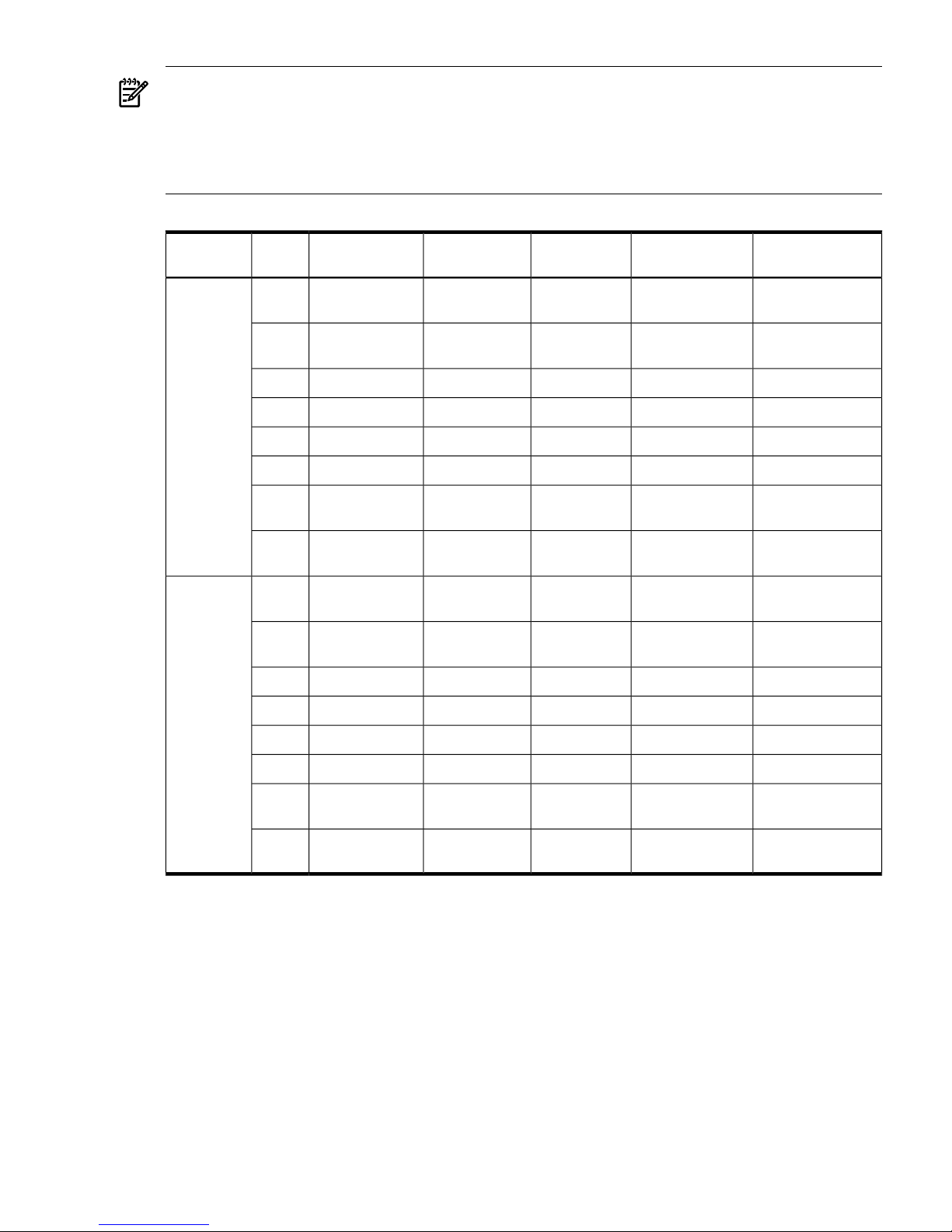
Table 1-9 PCIe Slot Types
PCI Mode SupportedSupported CardsRopesMaximum Peak
Bandwidth
Maximum MHzSlot
1
I/O Partition
PCI or PCI-X Mode
1
3.3 V001533 MB/s668
2
0
PCI or PCI-X Mode
1
3.3 V002/0031.06 GB/s1337
PCIe3.3 V004/0052.13 GB/s2666
PCIe3.3 V006/0072.13 GB/s2665
PCIe3.3 V014/0152.13 GB/s2664
PCIe3.3 V012/0132.13 GB/s2663
PCI or PCI-X Mode
1
3.3 V010/0111.06 GB/s1332
PCI or PCI-X Mode
1
3.3 V008/0091.06 GB/s1331
PCI or PCI-X Mode
1
3.3 V001533 MB/s668
2
1
PCI or PCI-X Mode
1
3.3 V002/0031.06 GB/s1337
PCIe3.3 V004/0052.13 GB/s2666
PCIe3.3 V006/0072.13 GB/s2665
PCIe3.3 V014/0152.13 GB/s2664
PCIe3.3 V012/0132.13 GB/s2663
PCI or PCI-X Mode
1
3.3 V010/0111.06 GB/s1332
PCI or PCI-X Mode
1
3.3 V008/0091.06 GB/s1331
1 Each slot will auto select the proper speed for the card installed up to the maximum speed for the slot. Placing high
speed cards into slow speed slots will cause the card to be driven at the slow speed.
2 Slot is driven by a single rope and has a maximum speed of 66 MHz.
Core I/O Card
Up to two core I/O cards can be plugged into the server. Two core I/O cards enable two I/O
partitions to exist in the server. The server can have up to two partitions. When a Server Expansion
Unit with two core I/O cards is attached to the server, two additional partitions can be configured.
A core I/O card can be replaced with standby power applied. The system power to the core I/O
is handled in the hardware the same way a hot-plug PCI/PCI-X card is handled. Standby power
to core I/O is handled by power manager devices to limit inrush current during insertion.
Detailed Server Description 31
Page 32
Core I/O Boot Paths
The servers internal I/O devices are located on the core I/O. The following table outlines the paths
assigned to the hard disk and removable media disk bays located on the front of the server
chassis. Core I/O card 0 refers to the core I/O located in the upper slot at the rear of the system.
Core I/O card 1 refers to the core I/O located in the lower slot at the rear of the system. Core I/O
cards 2 and 3 are located in the SEU (if available).
Table 1-10 Core I/O Boot Paths
DescriptionPathDeviceCore I/O Card
Core I/O 0 SYS LAN
connector.
0/0/0/1/01Gb LAN0
Hard drive located in upper
left disk bay.
0/0/0/2/0.6.0SCSI Drive0
Removable media DVD
(X=2) or DDS-4 (X=3) tape
drive located in the upper
disk bay.
0/0/0/2/1.X.0SCSI Drive0
Hard drive located in the
upper right disk bay.
0/0/0/3/0.6.0SCSI Drive0
SCSI drive connected to the
external SCSI Ultra3
connector on the core I/O
card.
0/0/0/3/1SCSI Drive0
Core I/O 1 SYS LAN
connector.
1/0/0/1/01Gb LAN1
Hard drive located in the
lower left disk bay.
1/0/0/2/0.6.0SCSI Drive1
Removable media DVD
(X=2) or DDS-4 (X=3) tape
drive located in the lower
disk bay.
1/0/0/2/1.X.0SCSI Drive1
Hard drive located in the
lower right disk bay.
1/0/0/3/0.6.0SCSI Drive1
SCSI drive connected to the
external SCSI Ultra3
connector on the core I/O
card.
1/0/0/3/1SCSI Drive1
Mass Storage (Disk) Backplane
Internal mass storage connections to disks are routed on the mass storage backplane, which has
connectors and termination logic. All hard disks are hot-plug but removable media disks are not
hot-plug. The server accommodates two internal, removable media devices. Power connectors
for removable media devices are on the mass storage backplane. For more information, refer to
Figure 1-13.
32 Server Overview
Page 33
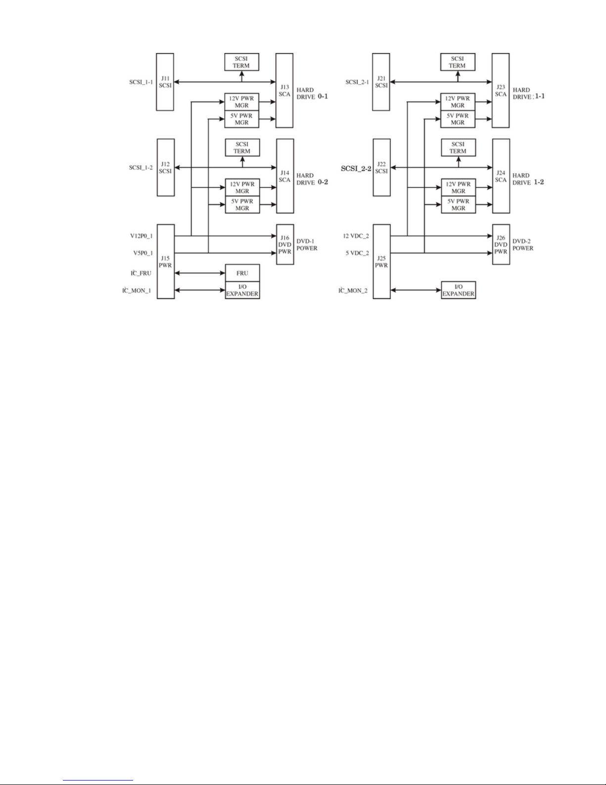
Figure 1-13 Mass Storage Block Diagram
Detailed Server Description 33
Page 34

34
Page 35
2 Installing the System
Inspect shipping containers when the equipment arrives at the site. Check equipment after the
packing has been removed. This chapter discusses how to receive, inspect and install the server.
Receiving and Inspecting the Server Cabinet
This section contains information about receiving, unpacking and inspecting the server cabinet.
NOTE: The server will ship in one of three different configurations. The configurations are:
• On a pallet installed in a server cabinet
• On a pallet for rack mount into an existing cabinet on the customer site
• On a pallet with a wheel kit for installation as a standalone server
HP shipping containers are designed to protect their contents under normal shipping conditions.
A tilt indicator is installed on each carton shipped. The tilt indicator has two windows, and each
window under normal conditions will show four beads present. If a carton has been mishandled,
accidentally dropped, or knocked against something, the tilt indicator will indicate missing
beads. If the container has been tilted to an angle that could cause equipment damage, the beads
in the indicator will roll to the upper position.
After the equipment arrives at the customer site, carefully inspect each carton for signs of shipping
damage. If the container is damaged, document the damage with photographs and contact the
transport carrier immediately.
NOTE: The factory provides an installation warranty that is effective from the time the customer
receives the shipment until Field Services turns the system over to the customer.
Upon inspection of a received system and during installation of the system, if any parts or
accessories are missing or defective, they will be replaced directly from the factory by a priority
process. To request replacement parts, the HP Installation Specialist must contact the local Order
Fulfillment group which will coordinate the replacement with the factory.
Unpacking the Server Cabinet
This section contains information about unpacking the server cabinet.
WARNING! Wear protective glasses while cutting the plastic bands around the shipping
container. These bands are under tension. When cut, they can spring back and cause serious eye
injury.
CAUTION: Observe all ESD safety precautions before attempting these procedures. Failure to
follow ESD safety precautions could result in damage to the server.
NOTE: Position the pallet to allow enough space to roll the cabinet off the pallet before starting.
Remove the server cabinet using the following steps:
1. Cut the polystrap bands around the shipping container.
2. Lift the cardboard top cap from the shipping box. See Figure 2-1.
Receiving and Inspecting the Server Cabinet 35
Page 36
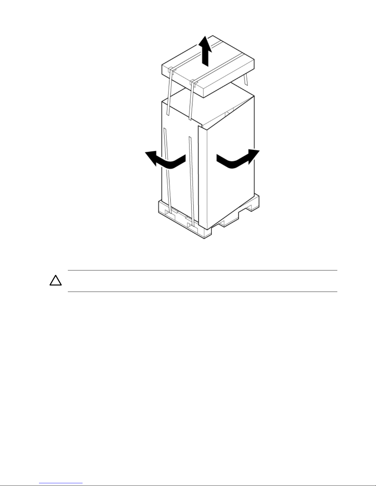
Figure 2-1 Removing the Polystraps and Cardboard
3. Remove the corrugated wrap from the pallet.
4. Remove the packing materials.
CAUTION: Cut the plastic wrapping material off rather than pull it off. Pulling the plastic
covering off represents an electrostatic discharge (ESD) hazard to the hardware.
5. Remove the four bolts holding down the ramps, and remove the ramps.
36 Installing the System
Page 37
NOTE: Figure 2-2 shows one ramp attached to the pallet on either side of the cabinet with
each ramp secured to the pallet using two bolts. In an alternate configuration, the ramps are
secured together on one side of the cabinet with one bolt.
Figure 2-2 Removing the Shipping Bolts and Plastic Cover
Receiving and Inspecting the Server Cabinet 37
Page 38
6. Remove the six bolts from the base that attaches the rack to the pallet.
Figure 2-3 Preparing to Roll Off the Pallet
WARNING! Be sure that the leveling feet on the rack are raised before you roll the rack
down the ramp, and any time you roll the rack on the casters. Use caution when rolling the
cabinet off the ramp. A single server in the cabinet weighs approximately 508 lb. It is strongly
recommended that two people roll the cabinet off the pallet.
After unpacking the cabinet, examine it for damage that might have been obscured by the shipping
container. If you discover damage, document the damage with photographs and contact the
transport carrier immediately.
If the equipment has any damage, the customer must obtain a damage claim form from the
shipping representative. The customer must complete the form and return it to the shipping
representative.
Securing the Cabinet
When in position, secure and stabilize the cabinet using the leveling feet at the corners of the
base (Figure 2-4). Install the anti-tip mechanisms on the bottom front and rear of the rack.
38 Installing the System
Page 39
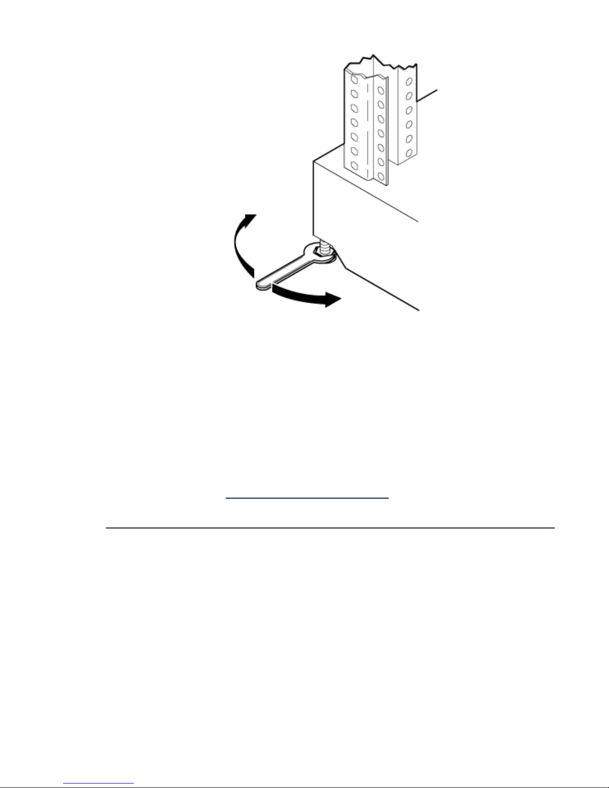
Figure 2-4 Securing the Cabinet
Standalone and To-Be-Racked Systems
Servers shipped in a stand-alone or to-be-racked configuration must have the core I/O handles
and the PCI towel bars attached at system installation. Obtain and install the core I/O handles
and PCI towel bars from the accessory kit A6093-04046. The towel bars and handles are the same
part. Refer to service note A6093A-11. This is the same accessory kit used for the HP 9000 rp8400
server.
Rack-Mount System Installation
Information is available to help with rack-mounting the server. This list is intended to guide the
HP Installation Specialist to the documentation that has been written by the Rack and Power
team.
The external Web site is: http://www.hp.com/racksolutions
The internal Web site is:
http://h18004.www1.hp.com/products/servers/proliantstorage/bcs-rackandpower/index.html
The web site is organized into the following topics:
Racks & Accessories
• Rack System/E
• Rack accessories
• Universal mounting kits
Power Management
• PDUs
• Cordsets
• Rackmounted UPS
System Management
• Console switches
• Flat panel/keyboards
Standalone and To-Be-Racked Systems 39
Page 40
Data cables
• CAT 5 cables
• Fibre optic cables
• SCSI cables
• SCSI terminators
Lifting the Server Cabinet Manually
Use this procedure only if no HP approved lift is available.
CAUTION: This procedure must only be performed by four qualified HP Service Personnel
utilizing proper lifting techniques and procedures.
1. Follow the instructions on the outside of the service packaging to remove the banding and
cardboard top from the server pallet.
2. Reduce the weight by removing all bulk power supplies and cell boards. Place each on an
ESD approved surface.
CAUTION: System damage can occur through improper removal and reinstallation of bulk
power supplies and cell boards. See Chapter 6, “Removal and Replacement” for the correct
procedures to remove and reinstall these components.
3. Locate the four positioning handles on the sides of the system. They are colored blue and
located close to each base corner of the unit.
4. Ensure that the tabs of the vertical support brackets are in the down position so they rest
on the slide rails when the server is lowered over the slides. There are two brackets on each
side of the server chassis.
5. Unfold the handles so that they are extended out from the unit. The server is now ready for
manual lifting by the four qualified HP Service Personnel.
6. Lift the server into place and secure as required.
7. After the server is secured, reinstall the previously removed cell boards and bulk power
supplies.
Using the RonI Model 17000 SP 400 Lifting Device
Use the lifter designed by the RonI company to rack-mount the server. The lifter can raise 400
lb/182 kg to a height of 5 feet. The lifter can be broken down into several components. When
completely broken down, no single component weighs more than 25 lb/12 kg. The ability to break
the lifter down makes it easy to transport from the office to the car and then to the customer site.
Documentation for the RonI lifter has been written by RonI and is available on the HP Cybrary:
http://cybrary.inet.cpqcorp.net/ARCHIVE/PUBS/USERS/LIFTOFLEX-17000.pdf. Complete details
on how to assemble the lifter, troubleshoot the lifter, and maintain the lifter are provided by
RonI.
Use the following procedure to unload the server from the pallet after the lifter is assembled.
40 Installing the System
Page 41
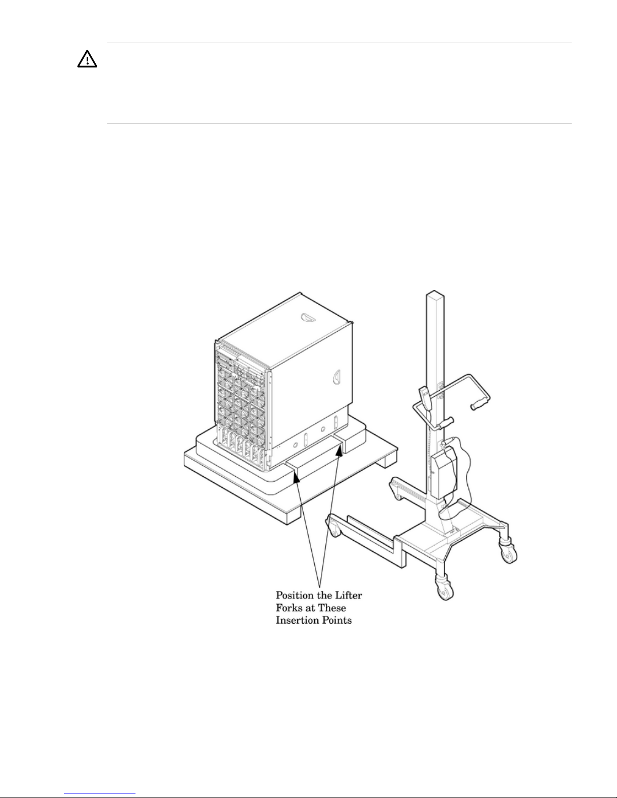
WARNING! Use caution when using the lifter. To avoid injury, because of the weight of the
server, center the server on the lifter forks before raising it off the pallet.
Always rack the server in the bottom of a cabinet for safety reasons. Never extend more than
one server from the same cabinet while installing or servicing another server product. Failure to
follow these instructions could result in the cabinet tipping over.
1. Obtain the HP J1528B Rack Integration Kit Installation Guide before proceeding with the
rack-mount procedure. This guide covers these important steps:
• Installing the anti-tip stabilizer kit (A5540A)
• Installing the ballast kit (J1479A)
• Installing the barrel nuts on the front and rear columns
• Installing the slides
2. Follow the instructions on the outside of the server packaging to remove the banding and
carton top from the server pallet.
3. Insert the lifter forks between the cushions (Figure 2-5).
Figure 2-5 Positioning the Lifter to the Pallet
4. Carefully roll the lift forward until it is fully positioned against the side of the server.
5. Slowly raise the server off the pallet until it clears the pallet cushions (Figure 2-6).
Using the RonI Model 17000 SP 400 Lifting Device 41
Page 42
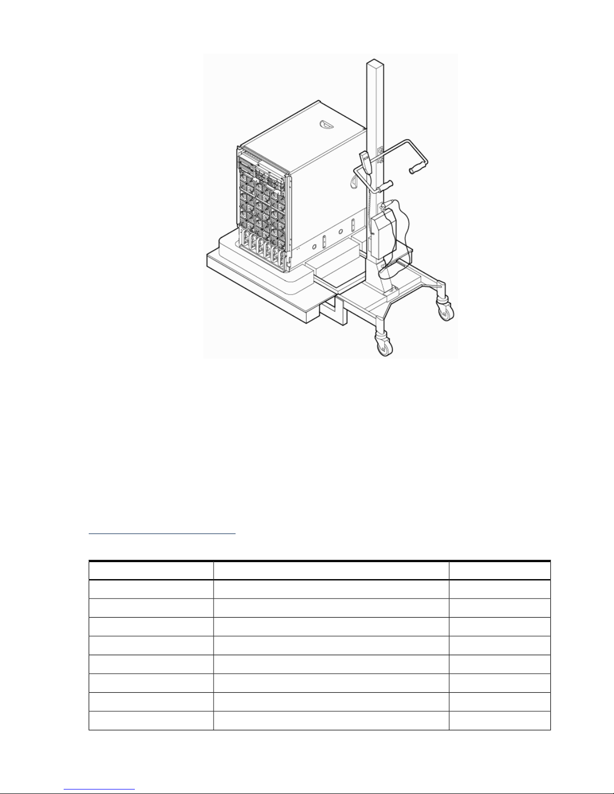
Figure 2-6 Raising the Server Off the Pallet Cushions
6. Carefully roll the lifter and server away from the pallet. Do not raise the server any higher
than necessary when moving it over to the rack.
7. Follow the HP J1528B Rack Integration Kit Installation Guide to complete these steps:
• Mounting the server to the slides
• Installing the cable management arm (CMA)
• Installing the interlock device assembly (if two servers are in the same cabinet)
Installing the Wheel Kit
Compare the packing list (Table 2-1) with the contents of the wheel kit before beginning the
installation. For a more updated list of part numbers, go to the HP Part Surfer web site at:
http://www.partsurfer.hp.com.
Table 2-1 Wheel Kit Packing List
QuantityDescriptionPart Number
2Caster coverA9904-04002
1Right side coverA9904-04007
1Left side coverA9904-04008
1Top coverA9904-04009
1Right front caster assemblyA6093-04082
1Right rear caster assemblyA6093-04083
1Left front caster assemblyA6093-04084
1Left rear caster assemblyA6093-04085
42 Installing the System
Page 43
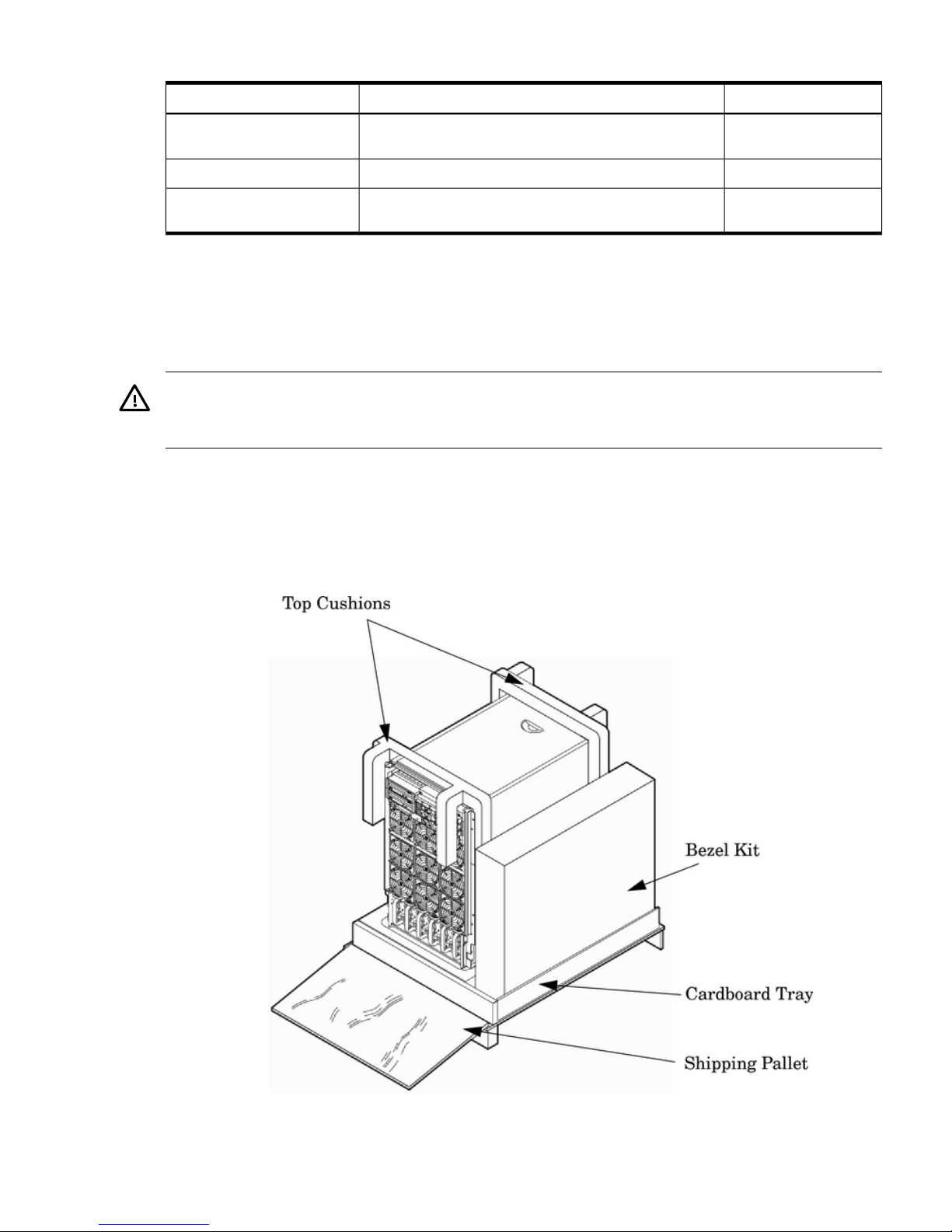
Table 2-1 Wheel Kit Packing List (continued)
QuantityDescriptionPart Number
8M4 x 0.7 8mm T15 steel zinc machine screw (used to attach
each caster to the chassis)
0515-2478
1Plywood unloading rampA6093-44013
2Phillips head wood screw (used to attach the ramp to the
pallet)
Not Applicable
Tools Required for Installation Use the following tools to perform the wheel kit installation:
• Diagonal side cutters
• Safety glasses
• Torx screwdriver with T-15 bit
• Phillips head screwdriver
WARNING! Wear protective glasses while cutting the plastic bands around the shipping
container. These bands are under tension. When cut, they can spring back and cause serious eye
injury.
Use the following procedure to install the wheel kit.
1. Cut and remove the polystrap bands securing the server to the pallet.
2. Lift the carton top from the cardboard tray resting on the pallet.
3. Remove the bezel kit carton and top cushions (Figure 2-7) from the pallet.
Figure 2-7 Server on Shipping Pallet
4. Unfold bottom cardboard tray.
Installing the Wheel Kit 43
Page 44
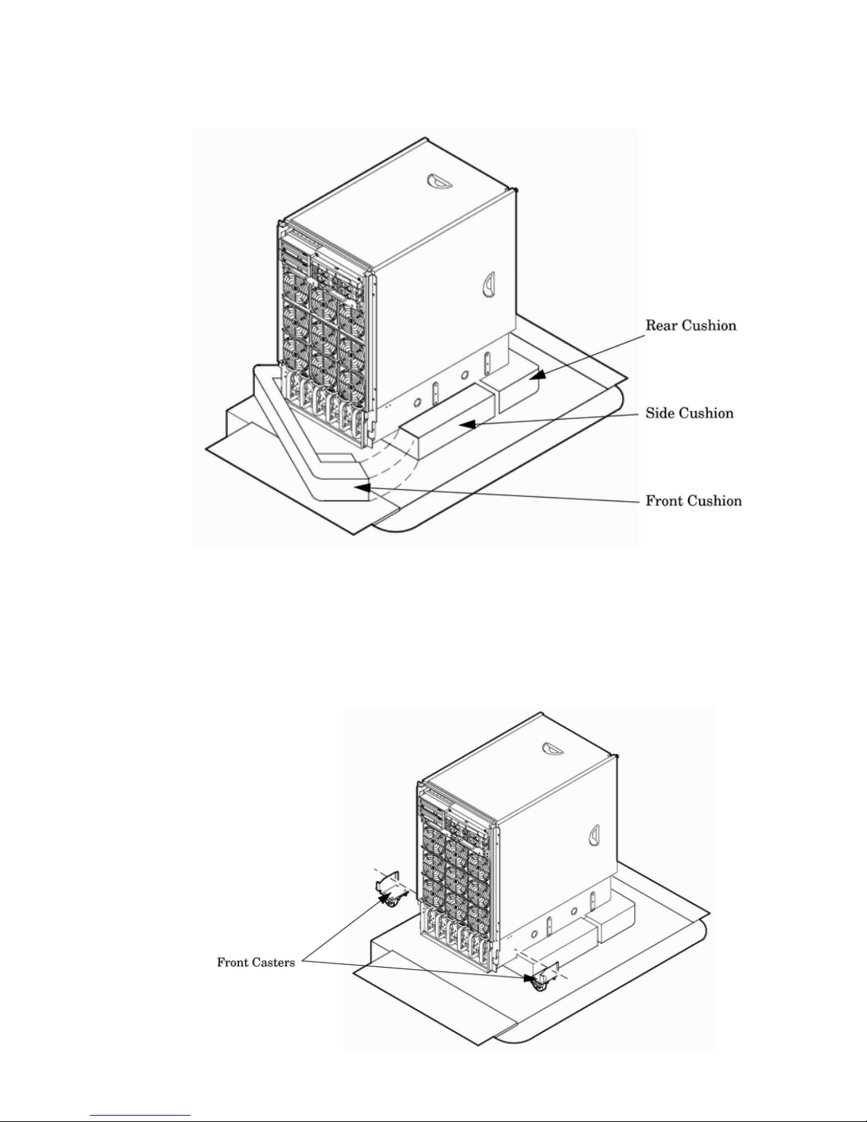
5. Remove the front cushion only (Figure 2-8). Do not remove any other cushions until further
instructed.
Figure 2-8 Removing Cushion from Front Edge of Server
6. Open the wheel kit box and locate the two front casters. The front casters are shorter in
length than the two rear casters. Each front caster is designed to fit only one corner of the
server (right front caster and left front caster).
7. Remove two of the eight screws from the plastic pouch. Attach one wheel caster to the front
of the server (Figure 2-9).
Figure 2-9 Attaching a Caster Wheel to the Server
44 Installing the System
Page 45
8. Attach the remaining front caster to the server using two more screws supplied in the plastic
pouch.
9. Remove the rear cushion at the rear of the server. Do not remove the remaining cushions.
10. Mount the two rear casters to the server using the remaining four screws.
11. Obtain the plywood ramp from the wheel kit.
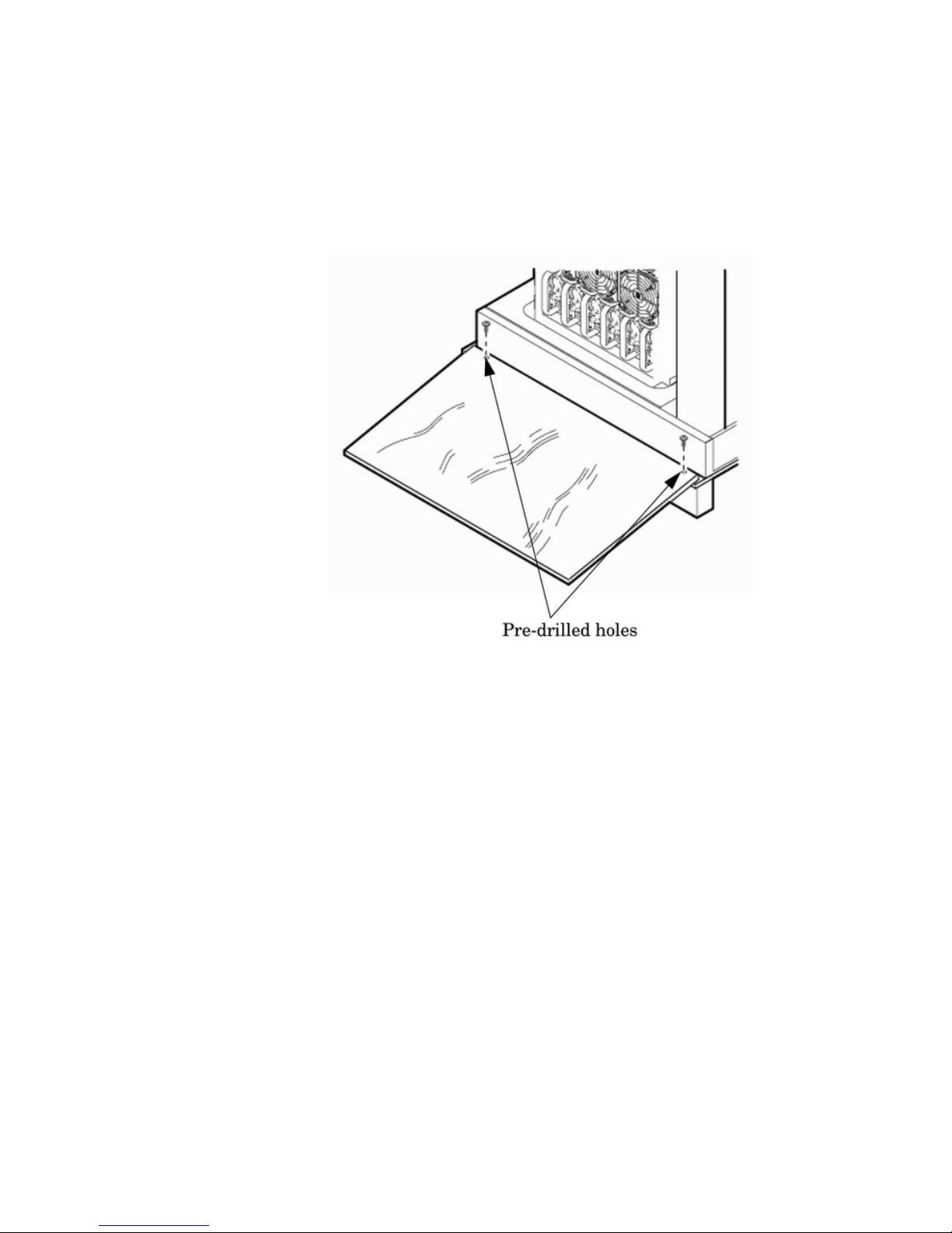
12. The ramp has two predrilled holes (Figure 2-10). Attach the ramp to the edge of the pallet
using the two screws taped to the ramp.
Figure 2-10 Attaching the Ramp to the Pallet
13. Remove the two side cushions from the server, (Figure 2-11) and unfold the cardboard tray
so that it lays flat on the pallet.
Installing the Wheel Kit 45
Page 46
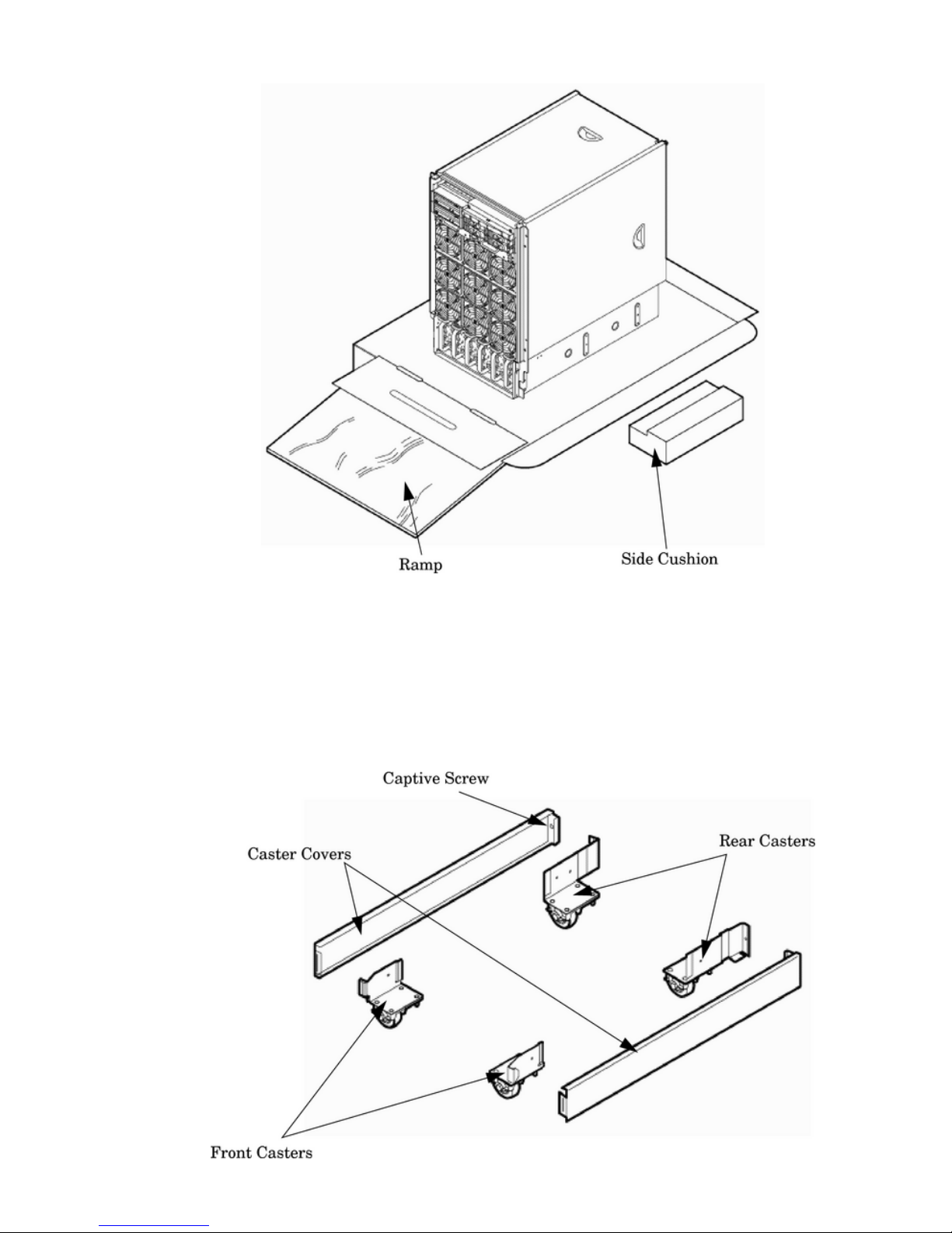
Figure 2-11 Removing Side Cushion from Server
14. Carefully roll the server off the pallet and down the ramp.
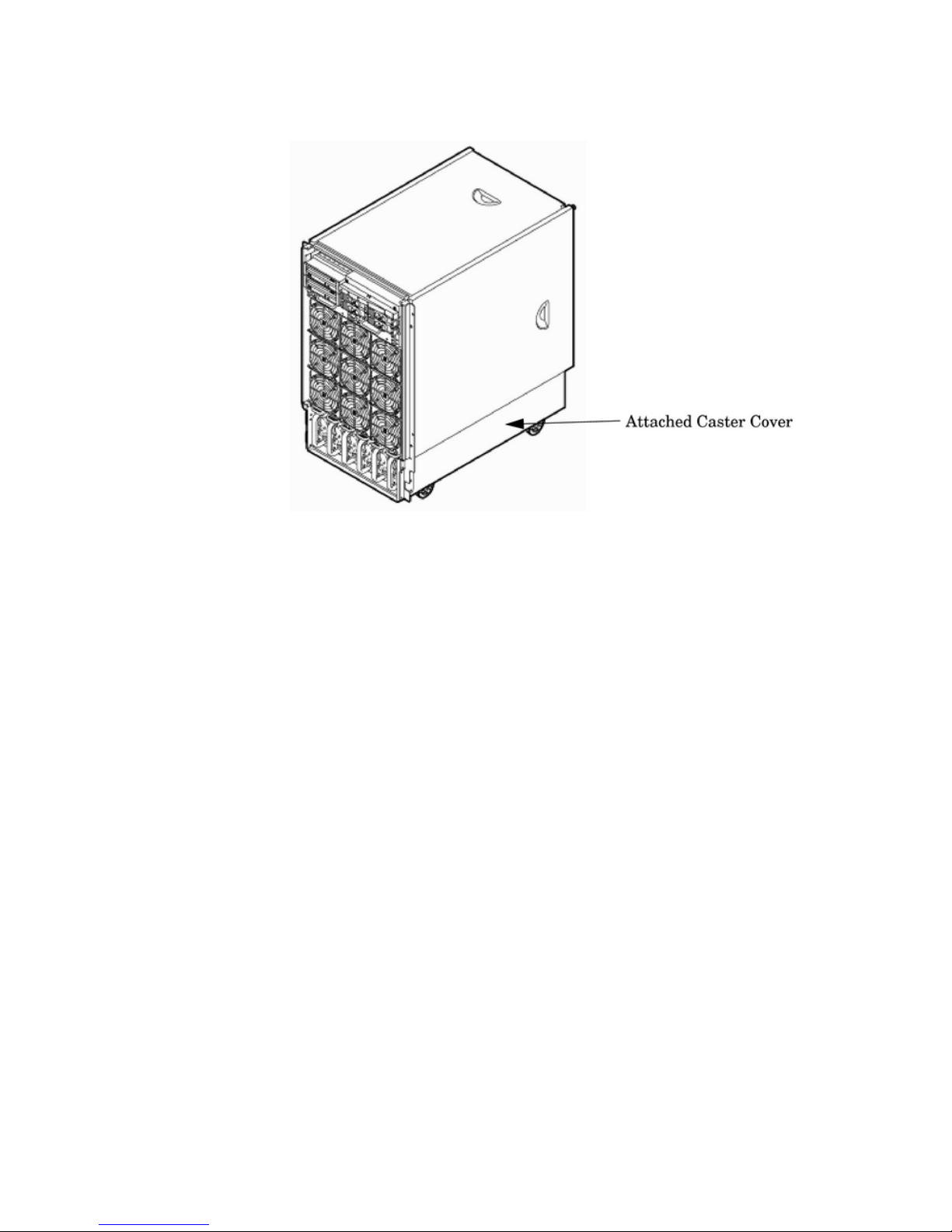
15. Obtain the caster covers from the wheel kit. Note that the caster covers are designed to fit
on either side of the server.
16. Insert the slot on the caster cover into the front caster (Figure 2-12). Secure the caster cover
to the server by tightening the captive screw on the cover at the rear of the server. Repeat
for the second caster cover.
Figure 2-12 Securing Each Caster Cover to the Server
46 Installing the System
Page 47
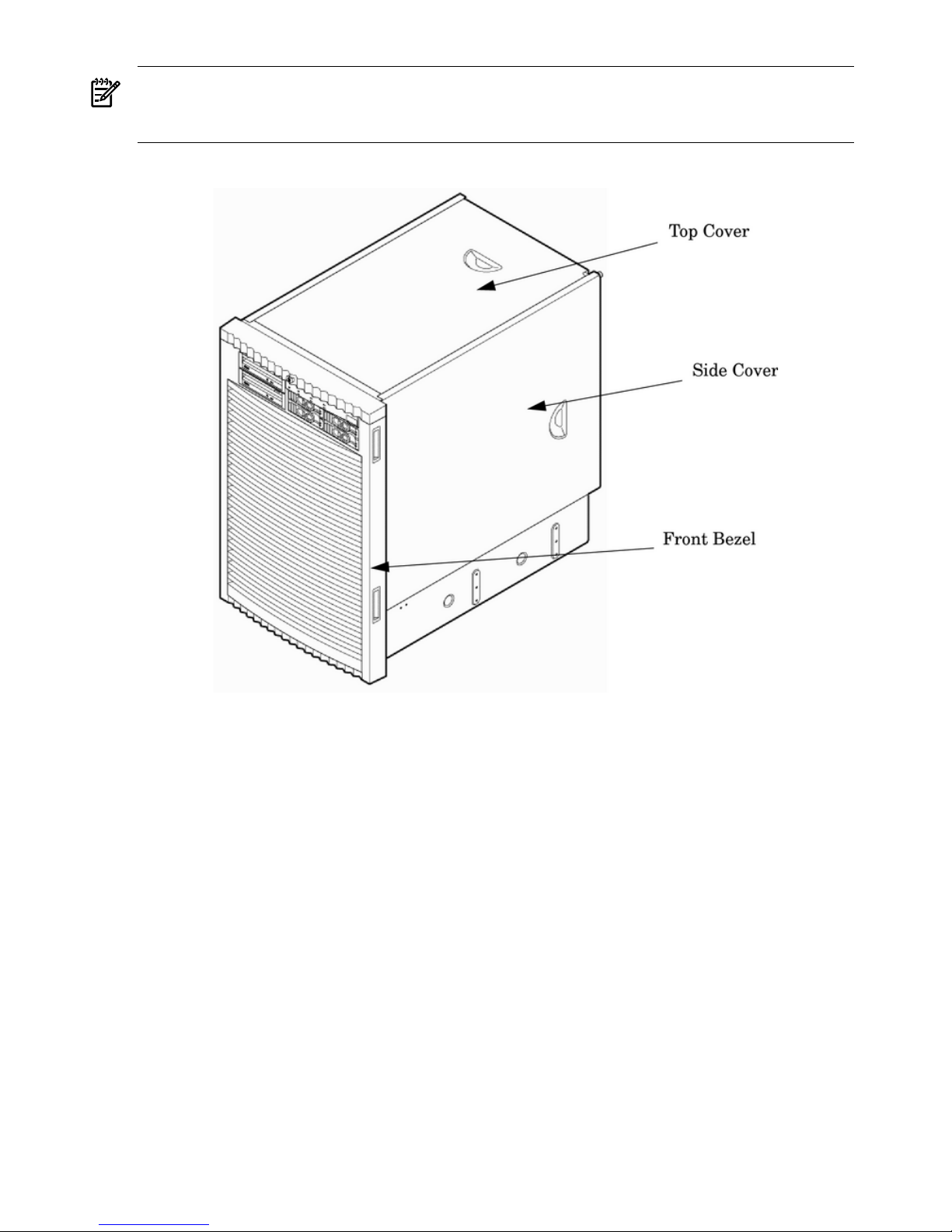
17. Snap the bezel cover into place on the front of the server. Figure 2-13 shows the server cabinet
with the wheel kit installed.
Figure 2-13 Completed Wheel Kit Installation
Installing the Top and Side Covers
This section describes the procedures for installing the top and side server covers.
Installing the Top and Side Covers 47
Page 48
NOTE: You may be need to remove existing top and side covers installed on the server before
installing the covers shipped with the wheel kit. If cover removal is not needed, go directly to
the next sections for installing the top and side cover.
Figure 2-14 Cover Locations
Removing the Top Cover
The following section describes the procedure for removing the top cover.
1. Connect to ground with a wrist strap.
2. Loosen the blue retaining screws securing the cover to the chassis (Figure 2-15).
3. Slide the cover toward the rear of the chassis.
4. Lift the cover up and away from the chassis.
5. Place the cover in a safe location.
48 Installing the System
Page 49
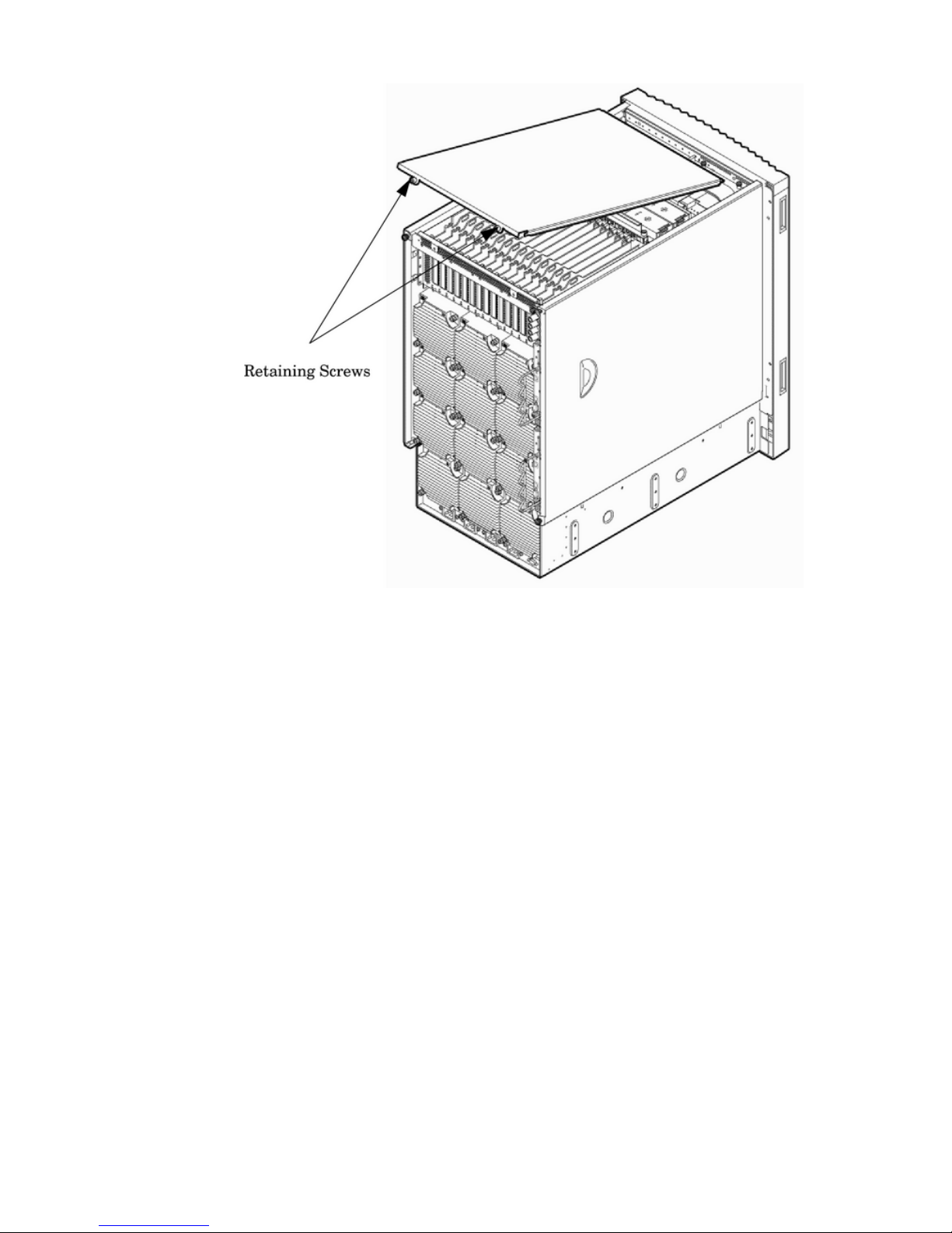
Figure 2-15 Top Cover Detail
Installing the Top Cover
The following section describes the procedure for installing the top cover.
1. Orient the cover according to its position on the chassis.
2. Slide the cover into position using a slow, firm pressure to properly seat the cover.
3. Tighten the blue retaining screws securing the cover to the chassis.
Removing the Side Cover
The following section describes the procedure for removing the side cover.
1. Connect to ground with a wrist strap.
2. Loosen the blue retaining screw securing the cover to the chassis (Figure 2-16).
Installing the Top and Side Covers 49
Page 50
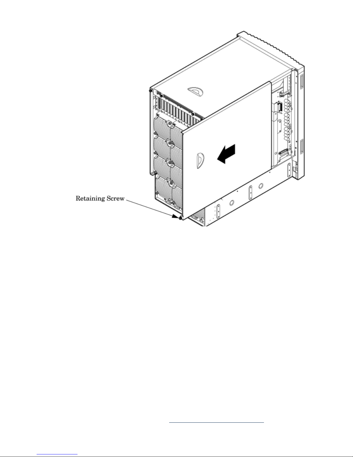
Figure 2-16 Side Cover Detail
3. Slide the cover from the chassis toward the rear of the system.
4. Place the cover in a safe location.
Installing the Side Cover
The following section describes the procedure for installing the side cover.
1. Orient the cover according to its position on the chassis.
2. Slide the cover into position using a slow, firm pressure to properly seat the cover.
3. Tighten the blue retaining screw securing the cover to the chassis.
Installing the Power Distribution Unit
The server may ship with a power distribution unit (PDU). Two 60 A PDUs are available for the
server. Each PDU is 3U high and is mounted horizontally between the rear columns of the server
cabinet. The 60 A PDUs are delivered with an IEC-309 60 A plug.
The 60 A NEMA2PDU has four 20 A circuit breakers and is constructed for North American
use. Each of the four circuit breakers has two IEC3-320 C19 outlets providing a total of eight
IEC-320 C19 outlets.
The 60A IEC PDU has four 16 A circuit breakers and is constructed for International use. Each
of the four circuit breakers has two IEC-320 C19 outlets providing a total of eight IEC-320 C19
outlets.
Each PDU is 3U high and is rack-mounted in the server cabinet.
Documentation for installation will accompany the PDU. The documentation can also be found
at the external Rack Solutions Web site at: http://www.hp.com/racksolutions
2. NEMA: National Electrical Manufacturers Association.
3. IEC: International Electrotechnical Commission.
50 Installing the System
Page 51
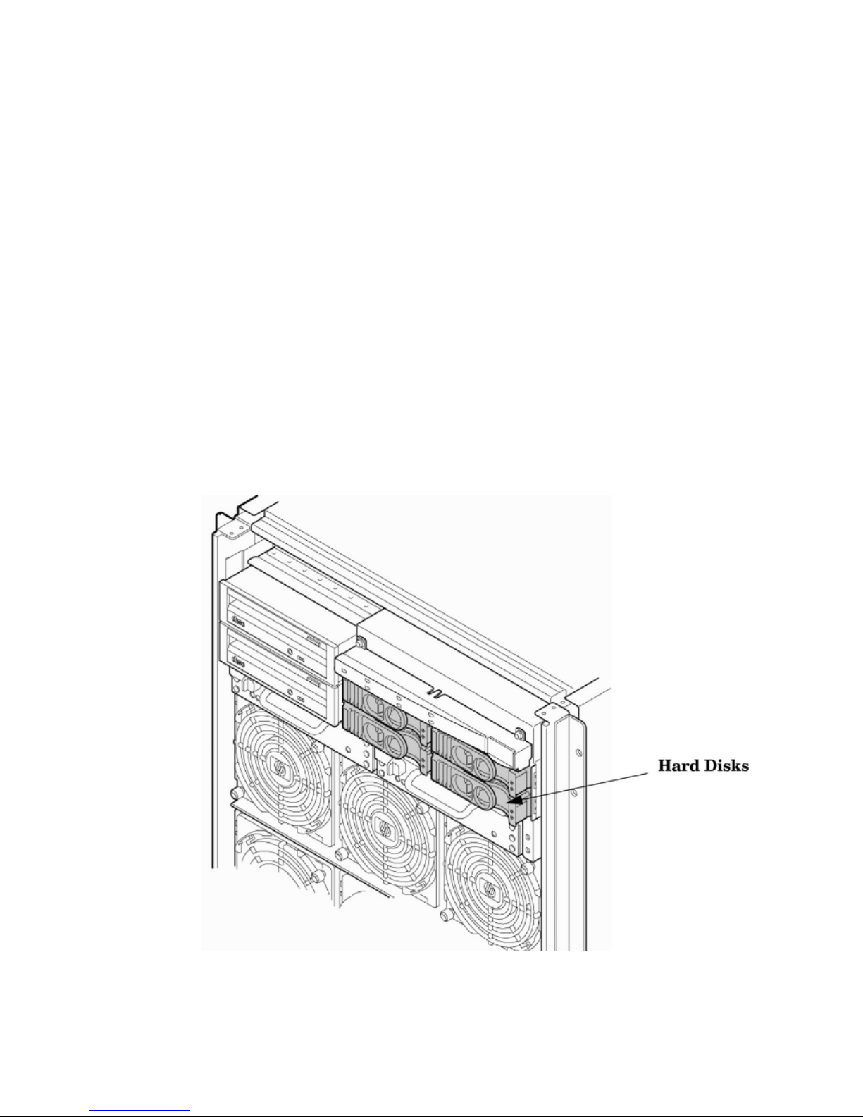
This PDU might be referred to as a Relocatable Power Tapoutside HP.
The PDU installation kit contains the following:
• PDU with cord and plug
• Mounting hardware
• Installation instructions
Installing Additional Cards and Storage
This section provides information on additional products ordered after installation and any
dependencies for these add-on products.
The following options can be installed in the server:
• Hard disk drive storage
• Removable media device storage
• PCI/PCI-X I/O cards
Installing an Additional Hard Disk Drive
The disk drives are located in the front of the chassis (Figure 2-17). The hard disk drives are
hot-plug drives.
A list of replacement disk drives for the server is in Appendix A of the HP Service Guide. The
list contains both removable media disk drives and hard disk drives.
Figure 2-17 Disk Drive Location
Use the following procedure to install the disk drives:
1. Be sure the front locking latch is open, then position the disk drive in the chassis.
2. Slide the disk drive into the chassis; apply a slow, firm pressure to properly seat the connector.
3. Press the front locking latch to secure the disk drive in the chassis.
Installing Additional Cards and Storage 51
Page 52
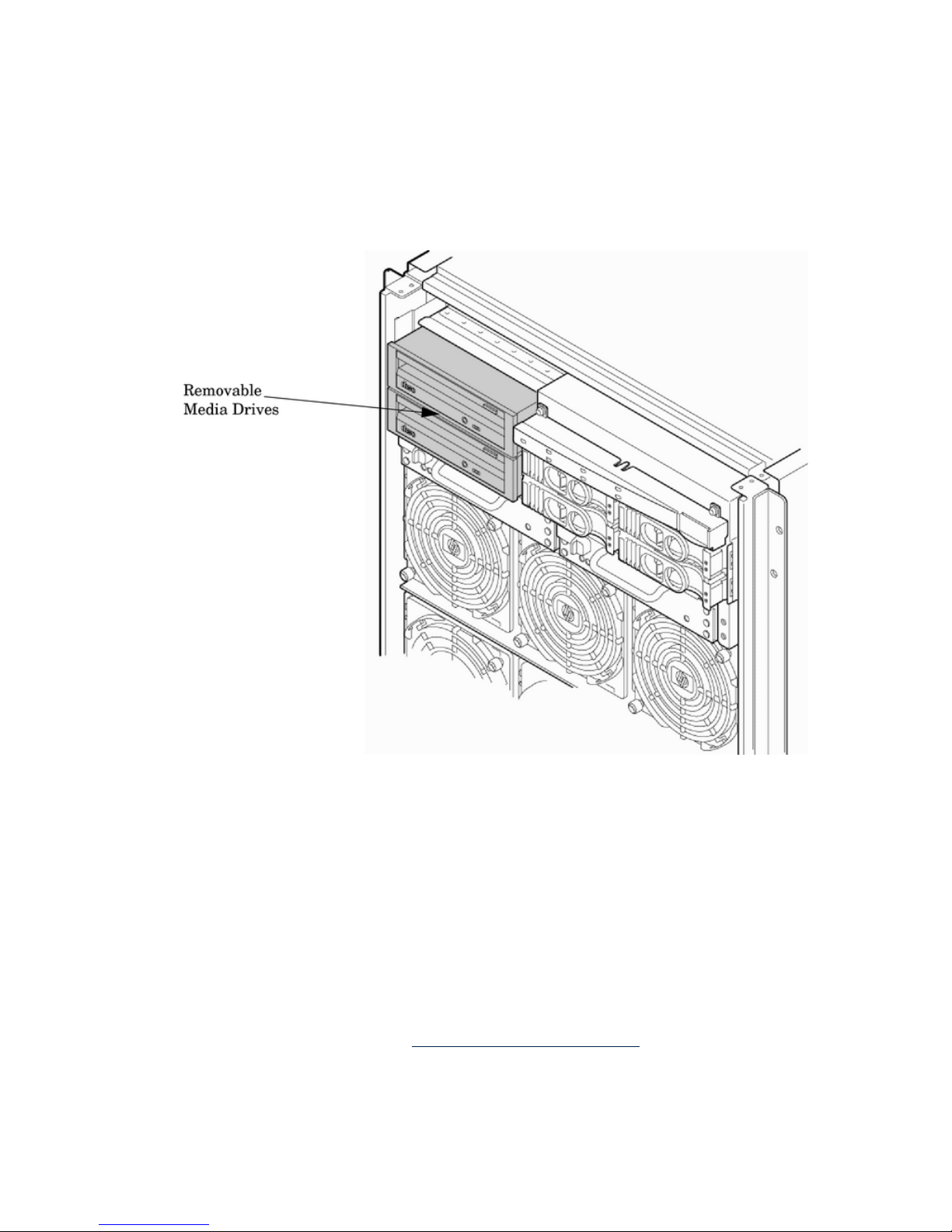
4. If the server OS is running, spin up the disk by entering one of the following commands:
#diskinfo -v /dev/rdsk/cxtxdx
#ioscan -f
Removable Media Drive Installation
The DVD drive or DDS-4 tape drives are located in the front of the chassis.
Figure 2-18 Removable Media Drive Location
If an upper drive is installed, remove it before installing a lower drive.
1. Remove the filler panel.
2. Connect the cables to the rear of the drive.
3. Install left and right media rails and clips.
4. Slide the drive in the chassis. Fold the cables out of the way.
5. Apply a slow, firm pressure to properly seat the drive in the chassis.
6. Latch the front locking tab to secure the drive in the chassis.
PCI-X Card Cage Assembly I/O Cards
Each of the two servers support a number of PCI and PCI-X I/O cards. Table 2-2 lists the cards
currently supported on the HP Integrity rx8640 server. For a more updated list of part numbers,
go to the HP Part Surfer web site at: http://www.partsurfer.hp.com.
52 Installing the System
Page 53

Table 2-2 HP Integrity rx8640 Server PCI-X/PCIe I/O Cards
VMSLinuxWindowsHP-UXCard DescriptionPart Number
Gigabit Ethernet (1000b-SX)A4926A
Gigabit Ethernet (1000b-T)A4929A
FCMS - TachliteA5158A
10/100b-TX (RJ45)A5230A
4-port 10/100b-TXA5506B
2-port Ultra2 SCSI/2-Port 100b-T ComboA5838A
Hyperfabric IIA6386A
64-port Terminal MUXA6749A
B2G FC TachliteA6795A
bbNext Gen 1000b-TA6825A
BB2-port 2Gb FCA6826A
1
BB1-port U160 SCSIA6828A
BB2-port U160 SCSIA6829A
bbNext Gen 1000b-SXA6847A
BBObsidian 2 VGA/USBA6869B
2
bbb1000b-SX Dual PortA7011A
bbb1000b-T Dual PortA7012A
BBBB2-port U320 SCSIA7173A
BBb1000b-T GigE/2G FC ComboA9782A
1
BBbPCI-X 1000b-T GigE/2G FC ComboA9784A
1
BBBB2-port Smart Array 6402 (U320)A9890A
BBB4-port Smart Array 6402 (U320)A9891A
BEmulex 9802 Fibre ChannelAB232A
1
PCI-X 2-port 4X InfiniBand HCA (HPC)AB286A
PCI-X 2-Port 4X InfiniBand HCA
(HPC)-RoHS
AB286C
bbb10 GbE - Fiber (PCI-X 133)AB287A
BBbBbBbU320 SCSI/GigE Combo CardAB290A
PCI-X 2-port 4X InfiniBand HCAAB345A
PCI-X 2–port 4X InfiniBand HCA-RoHSAB345C
BBQLogic 1-port 4Gb FC card (PCI-X 266)AB378A
1
BBBBQLogic 2-port 4Gb FC card (PCI-X 266)AB379A
1
BB1-Port 4Gb FC QLogic – AB378A
equivalent
AB429A
1
BBb2-port 1000b-T 2Gb FC ComboAB465A
1
BEmulex 1050DC Fibre ChannelAB466A
1
Installing Additional Cards and Storage 53
Page 54
Table 2-2 HP Integrity rx8640 Server PCI-X/PCIe I/O Cards (continued)
VMSLinuxWindowsHP-UXCard DescriptionPart Number
BEmulex 1050D Fibre ChannelAB467A
1
b4-Port 1000b-T EthernetAB545A
BBEmulex 4Gb/sAD167A
1
BBEmulex 4Gb/s DCAD168A
1
8-Port Terminal MUXAD278A
64-Port Terminal MUXAD279A
BBLO (USB/VGA/RMP)AD307A
2-port Serial (X25/FR/SDLC)J3525A
BBSA P600 (Redstone)337972-B21
PCIe Cards
BBEmulex 1–port 4Gb FC PCIeA8002A
BBEmulex 2–port 4Gb FC PCIeA8003A
BBBB2 Port 4Gb FC HBA PCIe (QLogic)AD300A
2 Ch 4X Infiniband HCA PCIeAD313A
2 Port 4Gb FC HBA PCIeAD335A
bbb2 Port 1000bT NIC PCIeAD337A
bbb2 Port 1000bT-SX NIC PCIeAD338A
BB1 Port 4Gb FC HBA PCIe (QLogic)AE311A
BBE500 SAS HBA (Bumper)AH226A
• B- Supports Mass Storage Boot
• b- Supports LAN Boot
• Bb- Support Mass Storage and LAN Boot
1. Factory integration (software load) of the OpenVMS, Windows, and Linux operating systems
via Fibre Channel is NOT supported.
2. Boot support is limited to OS installation, updating, and repairing media.
Table 2-3 lists the cards currently supported for the HP 9000 rp8440 server.
Table 2-3 HP 9000 rp8440 Server PCI-X I/O Cards
n/an/an/aHP-UXCard DescriptionPart Number
Gigabit Ethernet (1000b-SX)A4926A
Gigabit Ethernet (1000b-T)A4929A
FCMS - TachliteA5158A
B2–port FWD SCSIA5159B
10/100b-TX (RJ45)A5230A
4-port 10/100b-TXA5506B
B2-port Ultra2 SCSI/2-Port 100b-T ComboA5838A
Hyperfabric IIA6386A
1
54 Installing the System
Page 55

Table 2-3 HP 9000 rp8440 Server PCI-X I/O Cards (continued)
n/an/an/aHP-UXCard DescriptionPart Number
64-port Terminal MUXA6749A
B2G FC TachliteA6795A
1
bNext Gen 1000b-TA6825A
1
B2-port 2Gb FCA6826A
1
B1-port U160 SCSIA6828A
B2-port U160 SCSIA6829A
bNext Gen 1000b-SXA6847A
1
b1000b-SX Dual PortA7011A
1
b1000b-T Dual PortA7012A
1
BU160 RAID — SmartArray 5304A7143A
B2-port U320 SCSIA7173A
1
Bb1000b-T GigE/2G FC ComboA9782A
1
BbPCI-X 1000b-T GigE/2G FC ComboA9784A
1
B2-port Smart Array 6402 (U320)A9890A
1
B4-port Smart Array 6402 (U320)A9891A
1
10 GbE - Fiber (PCI-X 133)AB287A
1
BbU320 SCSI/GigE Combo CardAB290A
1
BQLogic 1-port 4Gb FC card (PCI-X 266)AB378A
1
BQLogic 1–port 4Gb FC card (PCI-X 266)AB378B
1
BQLogic 2-port 4Gb FC card (PCI-X 266)AB379A
1
BQLogic 2–port 4Gb FC card (PCI-X 266)AB379B
1
Bb2-port 1000b-T 2Gb FC ComboAB465A
1
b4-Port 1000b-T EthernetAB545A
1
Bb1–port 4Gb FC & 1–port GigE HBA PCI-X
RoHS
AD193A
1
Bb2–port 4Gb FC & 1–port GigE HBA PCI-X
RoHS
AD194A
1
8-Port Terminal MUXAD278A
1
64-Port Terminal MUXAD279A
1
bPCI/PCI-X 1–port 1000b-T AdapterAD331A
1
bPCI/PCI-X 1–port 1000b-SX AdapterAD332A
1
2-port Serial (X25/FR/SDLC)J3525A
1
Installing Additional Cards and Storage 55
Page 56
• B- Supports Mass Storage Boot
• b- Supports LAN Boot
• Bb- Supports Mass Storage and LAN Boot
1. Available with Factory Integration
IMPORTANT: The above list of part numbers is current and correct as of December 2006. Part
numbers change often. Check the following website to ensure you have the latest part numbers
associated with this server: http://partsurfer.hp.com/cgi-bin/spi/main
Installing an Additional PCI-X I/O Card
IMPORTANT: While the installation process for PCI/PCI-X cards and PCIe cards is the same,
PCIe cards are physically smaller than PCI-X cards and are not interchangeable. Check Table 1-9
(page 31) to verify the slot types and order.
NOTE: The PCI I/O card installation process varies depending on what version of the HP-UX
operating system you are running on your system. PCI I/O card installation procedures should
be downloaded from the http://docs.hp.com/ Web site. Background information and procedures
for adding a new PCI I/O card using online addition are found in:
• HP System Partitions Guide for HP-UX 11.11
• Interface Card OL* Support Guide for HP-UX 11.23
HP Lights Out Advanced/KVM Card
Overview
The Lights Out Advanced/KVM Card (LOA) is a PCI-X accessory card that can be installed into
any sx2000–based Integrity server to enable the advanced virtual graphics console (vKVM) and
virtual CD/DVD/ISO file (vMedia) features of the Integrity Lights Out Management Processor
(iLO/MP). The LOA card is also a graphics/USB card that offers physical video functionality for
servers running Windows, and USB functionality for servers running HP-UX, Windows, and
OpenVMS. All Lights Out Advanced features are fully enabled on the LOA card — there is no
additional “advanced pack” license to purchase. At present, vKVM is only available for servers
running Windows and vMedia is available for servers running HP-UX, Windows, and OpenVMS.
There are no current plans to support the LOA card under Linux.
Slotting Rules
The LOA card has specific slotting requirements that must be followed for full card functionality:
• Must be placed in a mode 1 PCI/PCI-X slot
• Must be placed in an I/O chassis with a functional core I/O card
• Must be only one LOA card in each partition
NOTE: HP recommends that you place the LOA card in the lowest numbered slot possible.
Downloading Drivers
The following website contains technical support for a wide range of HP Integrity servers,
including the capture of the latest drivers required for various hardware components. Refer to
this site regarding necessary drivers for supported PCI cards.
See: http://www.hp.com/support/itaniumservers
PCI I/O OL* Card Methods The following are three methods for performing OL* operations
on PCI I/O cards:
pdweb The Peripheral Device Tool (pdweb) Web-based method of performing
OL*.
56 Installing the System
Page 57
olrad
The command-line method of performing OL*.
Attention button The hardware system slot based method of performing OL*.
Adding a PCI I/O Card Using the Attention Button The following prerequisites for this procedure:
• Drivers for the card have already been installed.
• No drivers are associated with the slot.
• The green power LED is steady OFF. If the empty slot is in the ON state, use the
olradcommand or the pdweb tool to power the slot OFF.
• The yellow attention LED is steady OFF or is blinking if a user has requested the slot location.
• Refer to the host bus adapter (HBA) documentation for details on card installation.
• Run the olrad -q command to determine the status of all the PCI I/O slots.
• Obtain a copy of the interface card guide for instructions on preparing the operating system
for the online addition of the PCI I/O card before attempting to insert a PCI I/O card into
the PCI-X card cage assembly backplane slot.
This procedure describes how to perform an online addition of a PCI card using the attention
button for cards whose drivers support online addition or replacement (OLAR). The attention
button is also referred to as the doorbell.
1. Remove the top cover.
2. Remove the PCI bulkhead filler panel.
3. Flip the PCI manual release latch (MRL) for the card slot to the open position. See Figure 2-19.
4. Install the new PCI card in the slot.
NOTE: Apply a slow, firm pressure to properly seat the card into the backplane.
5. Flip the PCI MRL for the card slot to the closed position.
CAUTION: Working out of sequence or not completing the actions within each step could
cause the system to crash.
Do not press the attention button until the latch (MRL) is locked.
6. Press the attention button.
The green power LED will start to blink.
Installing Additional Cards and Storage 57
Page 58
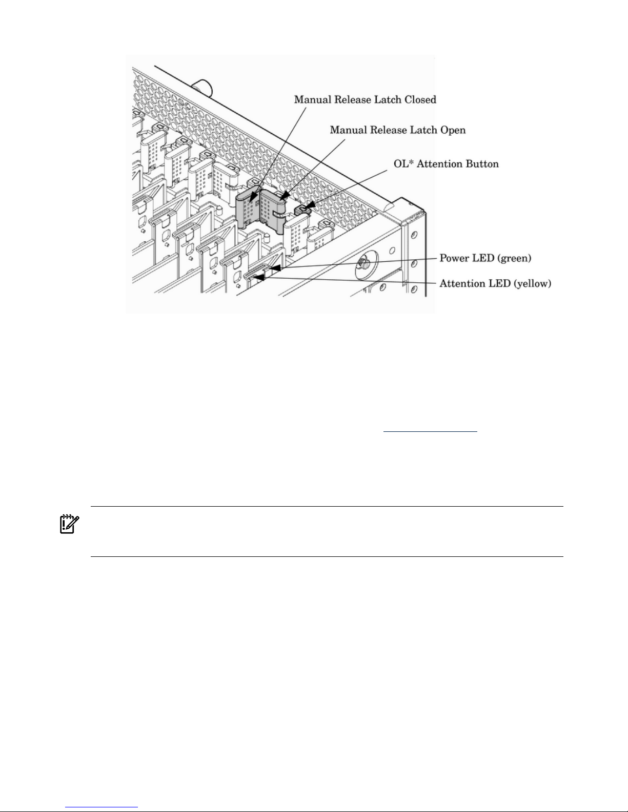
Figure 2-19 PCI I/O Slot Details
7. Wait for the green power LED to stop blinking and turn on solid.
8. Check for errors in the hotplugddaemon log file (default: /var/adm/hotplugd.log).
The critical resource analysis (CRA) performed while doing an attention button-initiated
add action is restrictive, and the action will not complete and will fail to protect critical
resources from being impacted.
For finer control over CRA actions, use the pdweb or the olrad command. Refer to the
Interface Card OL* Support Guide located on the Web at http://docs.hp.com, for details.
9. Replace the top cover.
10. Connect all cables to the installed PCI card.
Installing a A6869B VGA/USB PCI Card in a Server
IMPORTANT: If you are installing the A6869B in HP servers based on the sx1000 chipset, such
as HP Superdome, rx7620, or rx8620, the system firmware must be updated to a minimum
revision of 3.88.
The A6869B VGA/USB PCI card is a dual function combo card, hosting VGA and universal serial
bus (USB) controllers. Both of these devices sit behind a PCI-PCI bridge. The A6869B VGA/USB
PCI card operates at the conventional 66MHz/64 bit PCI rate and is universally keyed. All
signalling and form factors conform to the PCI Local Bus Specification 2.3. The VGA controller has
128Mbits of DDR-1 RAM for use as a frame buffer.
58 Installing the System
Page 59
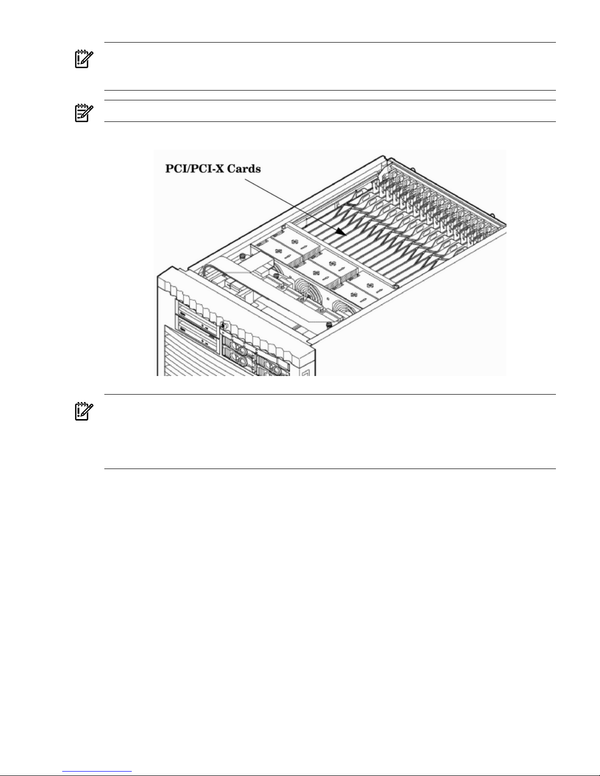
IMPORTANT: Search for available PCI slots that support the conventional clock speed to conserve
availability of higher speed PCI-X card slots to PCI-X cards that use the higher bandwidth. This
applies to mid-range as well as high-end HP server I/O PCI-X backplanes.
NOTE: The A6869B VGA/USB PCI card can be installed into any slot in a PCI/PCI-X backplane.
Figure 2-20 PCI/PCI-X Card Location
IMPORTANT: Some PCI I/O cards, such as the A6869B VGA/USB PCI card, cannot be added
or replaced online (while Windows remains running). For these cards, you must shut down
Windows on the nPartition before performing the card replacement or addition. See the section
on Shutting Down nPartitions and Powering off Hardware Components in the appropriate
service guide.
1. If the A6869B VGA/USB PCI card is currently not installed, follow proper procedures to
shut down the nPartition and power-off the appropriate PCI power domain.
2. Locate a vacant conventional clock speed PCI slot where the A6869B VGA/USB PCI card
will reside.
3. Position the PCI card over the empty slot, observing that edge connector keyways match
on the PCI backplane connector.
4. Using a slow firm pressure, seat the card down into the slot.
5. Connect the monitor, mouse, and keyboard cables to the card.
6. Connect power, and turn on the monitor.
7. Follow proper procedures to power-on the PCI power domain and boot the Windows
nPartition.
Once Windows has completely booted, the video, keyboard and mouse are ready for use.
Troubleshooting the A6869B VGA/USB PCI Card
The following provides some troubleshooting solutions and a URL to a useful reference site.
Installing Additional Cards and Storage 59
Page 60

No Console Display
Hardware problem.
* Must have supported power enabled.
* Must have a functional VGA/USB PCI card.
* Must have a functional PCI slot. Select another slot on same partition/backplane.
* Must have the VGA/USB PCI card firmly seated in PCI backplane slot.
* Must have a supported monitor.
* Must have verified cable connections to VGA/USB PCI card.
Black Screen. No text displayed.
* Ensure system FW supports the VGA/USB PCI card.
* Ensure graphics resolution is compatible and set correctly.
Display unreadable.
Reference URL
There are many features available for HP Servers at this website including links to download
Windows Drivers.
HP Servers Technical Support
http://www.hp.com/support/itaniumservers
System Console Selection
Each operating system requires that the correct console type be selected from the firmware
selection menu. The following section describes how to determine the correct console device.
If an operating system is being installed or the system configuration is being changed the system
console setting must be checked to ensure it matches the hardware and OS. Not checking the
console selection can result in the system using an unexpected device as a console, which can
appear as a system hang when booting.
1. Determine the console you want to use.
Depending on your operating system and your hardware you can select one of two possible
devices as your system console. The possibilities are:
• Management Processor (MP) Serial Port
• VGA device
60 Installing the System
Page 61
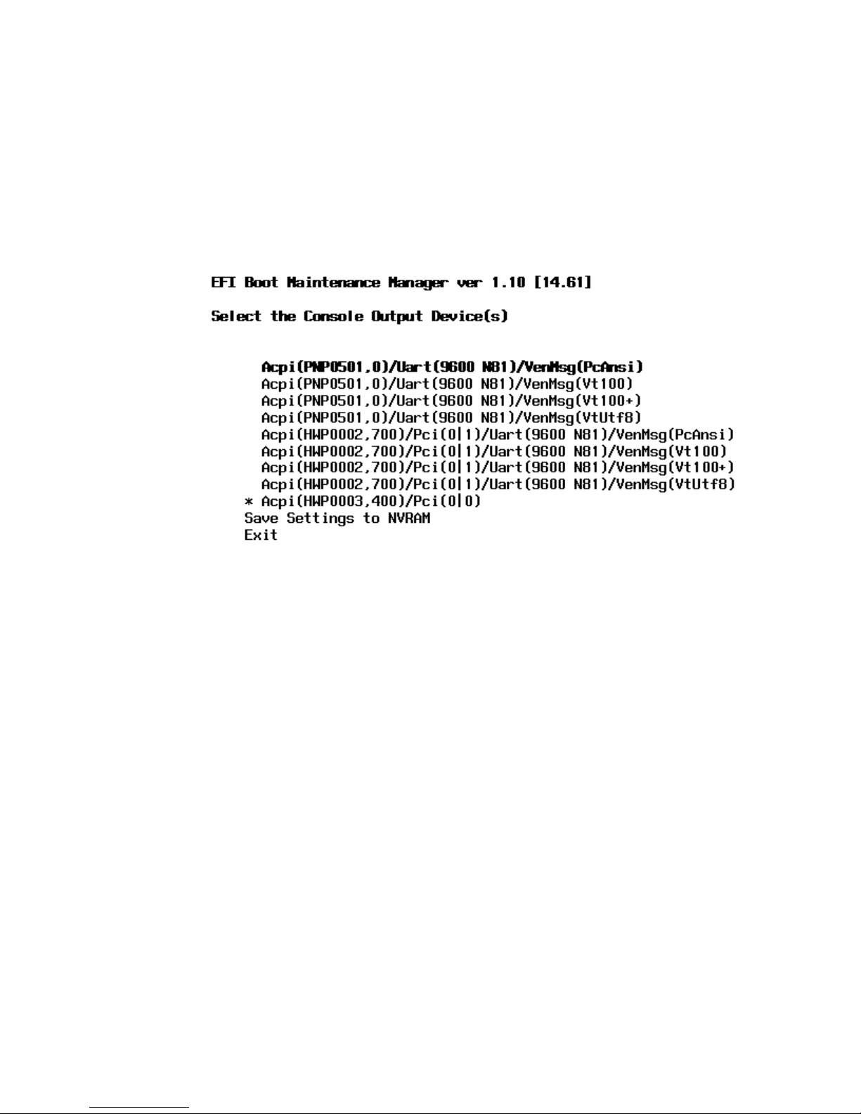
2. Select the appropriate console device (deselect unused devices):
a. Choose the “Boot option maintenance menu” choice from the main Boot Manager Menu.
b. Select the Console Output, Input or Error devices menu item for the device type you
are modifying:
• “Select Active Console Output Devices”
• “Select Active Console Input Devices”
• “Select Active Console Error Devices”
c. Available devices will be displayed for each menu selection. Figure 2-21 shows a typical
output of selecting the Console Output Devices menu.
Figure 2-21 Console Output Device menu
d. Choose the correct device for your system and deselect others. See “Interface Differences
Between Itanium-based Systems” for details about choosing the appropriate device.
e. Select “Save Settings to NVRAM” and then “Exit” to complete the change.
f. A system reset is required for the changes to take effect.
VGA Consoles
Any device that has a PCI section in its path and does not have a UART section will be a VGA
device. If you require a VGA console, choose the device and unmark all others. Figure 2-21 shows
that a VGA device is selected as the console.
Interface Differences Between Itanium-based Systems
Each Itanium-based system has a similar interface with minor differences. Some devices may
not be available on all systems depending on system design or installed options.
Other Console Types
Any device that has a UART section but no PCI section is a system serial port. To use the system
serial port (if available) as your console device, select the system serial device entry that matches
your console type (PcAnsi, Vt100, Vt100+, VtUtf8) and deselect everything else.
If you choose either a system or MP serial port HP recommends that you use a vt100+ capable
terminal device.
Additional Notes on Console Selection
Each Operating System makes decisions based on the EFI Boot Maintenance Manager menu’s
Select Active Console selections to determine where to send its output. If incorrect console devices
System Console Selection 61
Page 62
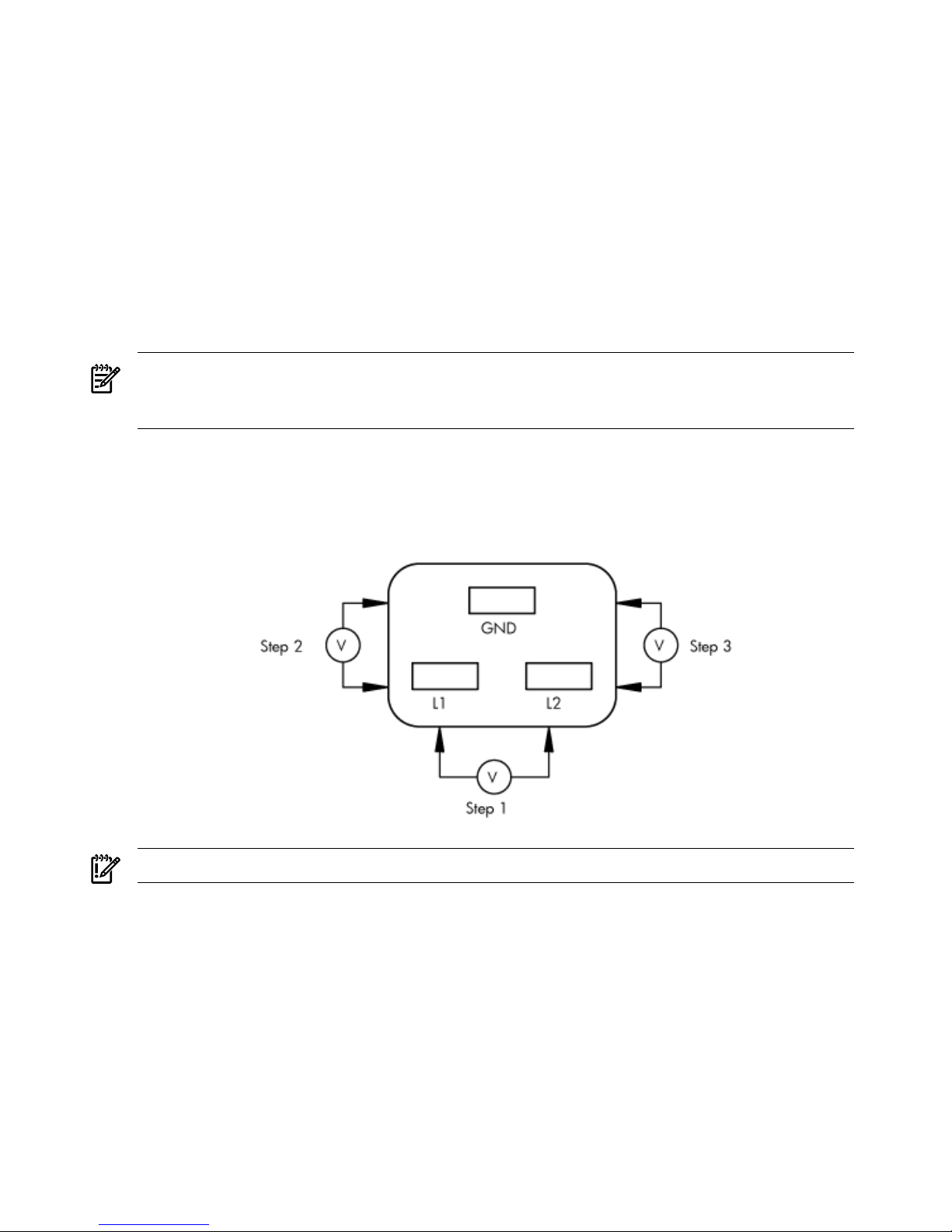
are chosen the OS may fail to boot or will boot with output directed to the wrong location.
Therefore, any time new potential console devices are added to the system or anytime NVRAM
on the system is cleared console selections should be reviewed to ensure that they are correct.
Cabling and Powering On the Server
After the system has been unpacked and moved into position, it must be connected to a source
of AC power. The AC power must be checked for the proper voltage before the system is powered
up. This chapter describes these activities.
Checking the Voltage
This section provides voltage check information for use on the customer site. The emphasis is
on measuring the voltages at the power cord plug end specified as an IEC-320 C19 type plug.
This is the end that plugs directly into the back of the server cabinet.
NOTE: Perform these procedures for each power cord that will be plugged directly into the
back of the server cabinet. If you do not obtain the expected results from this procedure during
the voltage check, refer to the section titled “Voltage Check (Additional Procedure)” (page 65).
Verifying the Voltage Range of the Recptacle
Use this procedure to measure the voltage between L1 and L2, L1 to ground, and L2 to ground.
Refer to Figure 2-22 for voltage reference points when performing the following measurements.
Figure 2-22 Voltage Reference Points for IEC-320 C19 Plug
IMPORTANT: Perform these measurements for every power cord that plugs into the server.
1. Measure the voltage between L1 and L2. This is considered to be a phase-to-phase
measurement in North America. In Europe and certain parts of Asia-Pacific, this measurement
is referred to as a phase-to-neutral measurement. The expected voltage should be between
200–240 V AC regardless of the geographic region.
2. Measure the voltage between L1 and ground. In North America, verify that this voltage is
between 100–120 V AC. In Europe and certain parts of Asia-Pacific, verify that this voltage
is between 200–240 V AC.
3. Measure the voltage between L2 and ground. In North America, verify that this voltage is
between 100–120 VAC. In Europe and certain parts of Asia-Pacific, verify that this voltage
is 0 (zero) V AC.
Table 2-4 provides single phase voltage measurement examples specific to the geographic region
where these measurements are taken.
62 Installing the System
Page 63
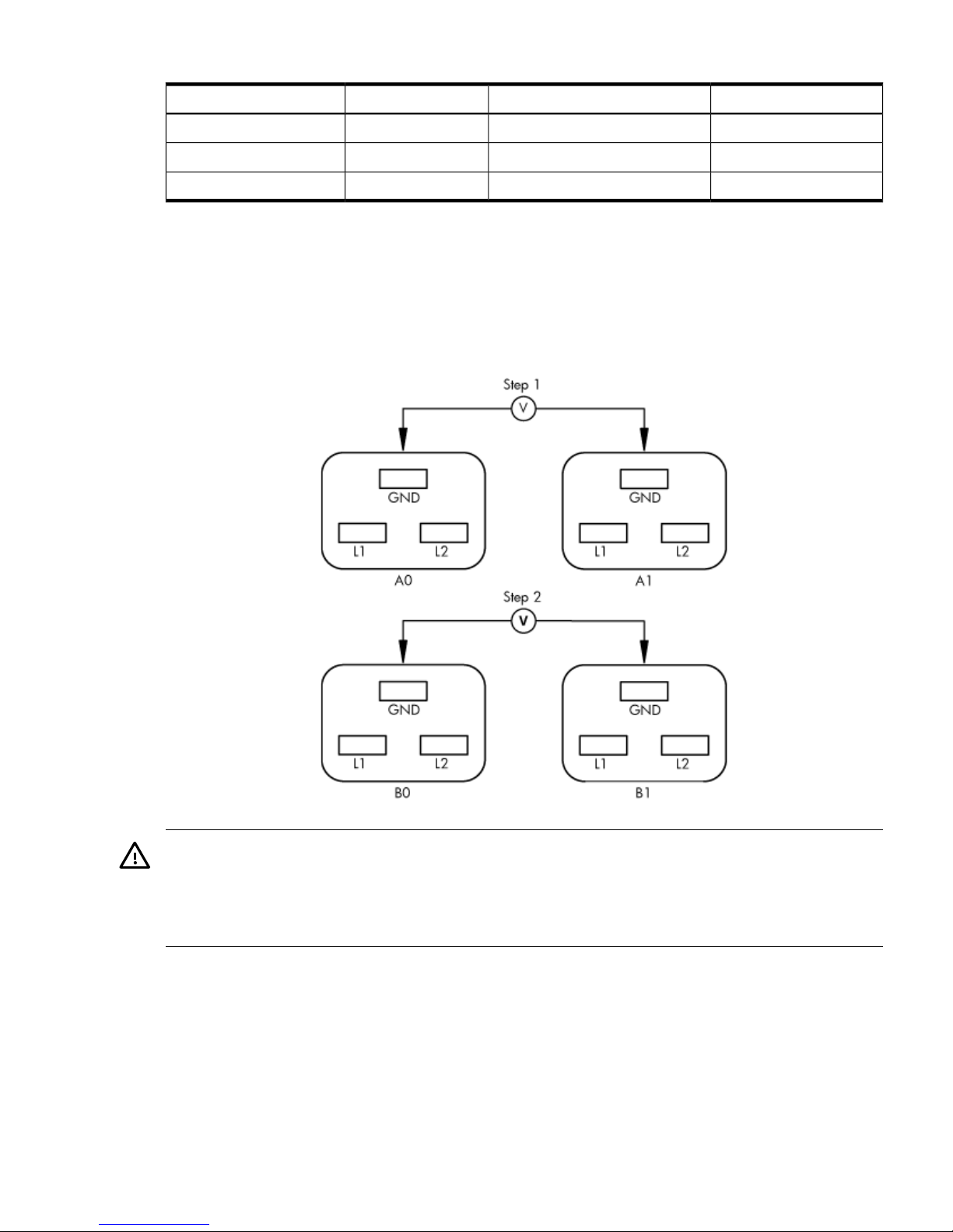
Table 2-4 Single Phase Voltage Examples
Europe
1
North AmericaJapan
230 V208 V or 240 V210 VL1 to L2
230 V120 V105 VL1 to ground
0 V120 V105 VL2 to ground
1 In some European countries, there might not be a polarization.
Verifying the Safety Ground (Single Power Source)
Use this procedure to measure the voltage level between A0 and A1. It also verifies the voltage
level between B0 and B1. Take measurements between ground pins. Refer to Figure 2-23 for
ground reference points when performing these measurements.
Figure 2-23 Safety Ground Reference Check — Single Power Source
WARNING! SHOCK HAZARD
Risk of shock hazard while testing primary power.
Use properly insulated probes.
Be sure to replace access cover when finished testing primary power.
1. Measure the voltage between A0 and A1 as follows:
1. Take the AC voltage down to the lowest scale on the volt meter.
2. Insert the probe into the ground pin for A0.
3. Insert the other probe into the ground pin for A1.
4. Verify that the measurement is between 0-5 V AC.
If the measurement is 5 V or greater, escalate the situation. Do not attempt to plug the power
cord into the server cabinet.
Cabling and Powering On the Server 63
Page 64
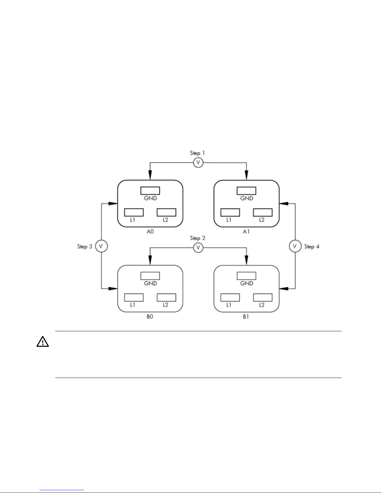
2. Measure the voltage between B0 and B1 as follows:
1. Take the AC voltage down to the lowest scale on the volt meter.
2. Insert the probe into the ground pin for B0.
3. Insert the other probe into the ground pin for B1.
4. Verify that the measurement is between 0-5 V AC.
If the measurement is 5 V or greater, escalate the situation. Do not attempt to plug the power
cord into the server cabinet.
Verifying the Safety Ground (Dual Power Source)
Use this procedure to measure the voltage level between A0 and A1, between B0 and B1, between
A0 and B0, and between A1 and B1. Take all measurements between ground pins. Refer to
Figure 2-24 for ground reference points when performing these measurements.
Figure 2-24 Safety Ground Reference Check — Dual Power Source
WARNING! SHOCK HAZARD
Risk of shock hazard while testing primary power.
Use properly insulated probes.
Be sure to replace access cover when finished testing primary power.
1. Measure the voltage between A0 and A1 as follows:
1. Take the AC voltage down to the lowest scale on the volt meter.
2. Insert the probe into the ground pin for A0.
3. Insert the other probe into the ground pin for A1.
4. Verify that the measurement is between 0-5 V AC.
If the measurement is 5 V or greater, escalate the situation. Do not attempt to plug the power
cord into the server cabinet.
2. Measure the voltage between B0 and B1 as follows:
64 Installing the System
Page 65

1. Take the AC voltage down to the lowest scale on the volt meter.
2. Insert the probe into the ground pin for B0.
3. Insert the other probe into the ground pin for B1.
4. Verify that the measurement is between 0-5 V AC.
If the measurement is 5 V or greater, escalate the situation. Do not attempt to plug the power
cord into the server cabinet.
3. Measure the voltage between A0 and B0 as follows:
1. Take the AC voltage down to the lowest scale on the volt meter.
2. Insert the probe into the ground pin for A0.
3. Insert the other probe into the ground pin for B0.
4. Verify that the measurement is between 0-5 V AC.
If the measurement is 5 V or greater, escalate the situation. Do not attempt to plug the power
cord into the server cabinet.
4. Measure the voltage between A1 and B1 as follows:
1. Take the AC voltage down to the lowest scale on the volt meter.
2. Insert the probe into the ground pin for A1.
3. Insert the other probe into the ground pin for B1.
4. Verify that the measurement is between 0-5 V AC.
If the measurement is 5 V or greater, escalate the situation. Do not attempt to plug the power
cord into the server cabinet.
Voltage Check (Additional Procedure)
The voltage check ensures that all phases (and neutral, for international systems) are connected
correctly to the cabinet and that the AC input voltage is within limits.
Perform this procedure if the previous voltage check procedure did not yield the expected results.
NOTE: If you use an uninterrupted power supply (UPS), refer to applicable UPS documentation
for information on connecting the server and checking the UPS output voltage. UPS user
documentation is shipped with the UPS. Documentation is also available at:
http://www.hp.com/racksolutions.
1. Verify that site power is OFF.
2. Open the site circuit breakers.
3. Verify that the receptacle ground connector is connected to ground. Refer to Figure 2-25 for
connector details.
4. Set the site power circuit breaker to ON.
Cabling and Powering On the Server 65
Page 66
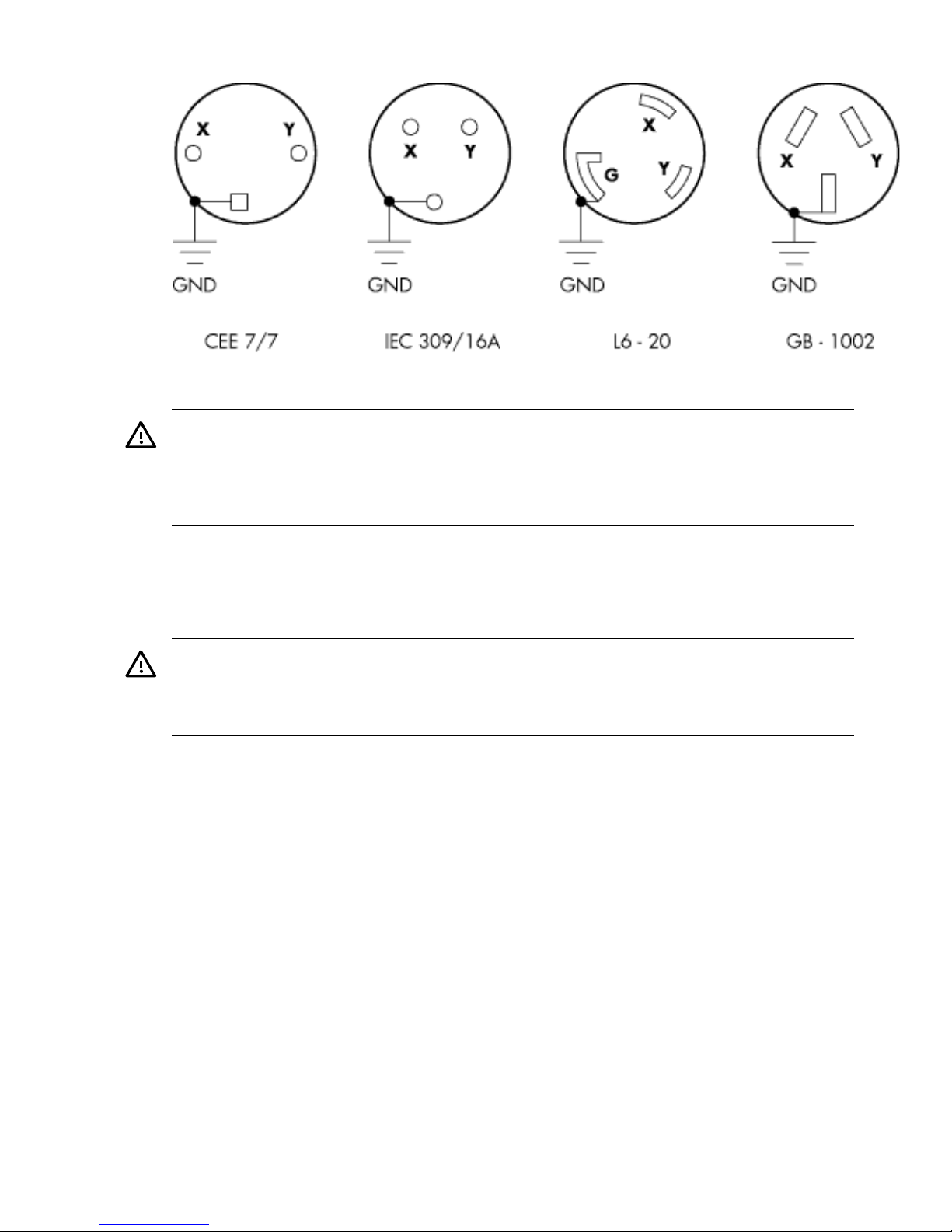
Figure 2-25 Wall Receptacle Pinouts
5. Verify that the voltage between receptacle pins X and Y is between 200–240 V AC.
WARNING! SHOCK HAZARD
Risk of shock hazard while testing primary power.
Use properly insulated probes.
Be sure to replace access cover when finished testing primary power.
6. Set the site power circuit breaker to OFF.
7. Route and connect the server power connector to the site power receptacle.
1. For locking type receptacles, line up the key on the plug with the groove in the receptacle.
2. Push the plug into the receptacle and rotate to lock the connector in place.
WARNING! Do not set site AC circuit breakers serving the processor cabinets to ON before
verifying that the cabinet has been wired into the site AC power supply correctly. Failure
to do so can result in injury to personnel or damage to equipment when AC power is applied
to the cabinet.
8. Set the site AC circuit breaker to ON.
9. Set the server power to ON.
10. Check that the indicator light on each power supply is lit.
Connecting AC Input Power
The server can receive AC input from two different AC power sources. If two separate power
sources are available, each source can be plugged into the server, increasing system reliability if
one power source fails. The main power source is defined to be A0 and A1. The redundant power
source is defined to be B0 and B1. See Figure 2-26 for the AC power input label scheme.
66 Installing the System
Page 67
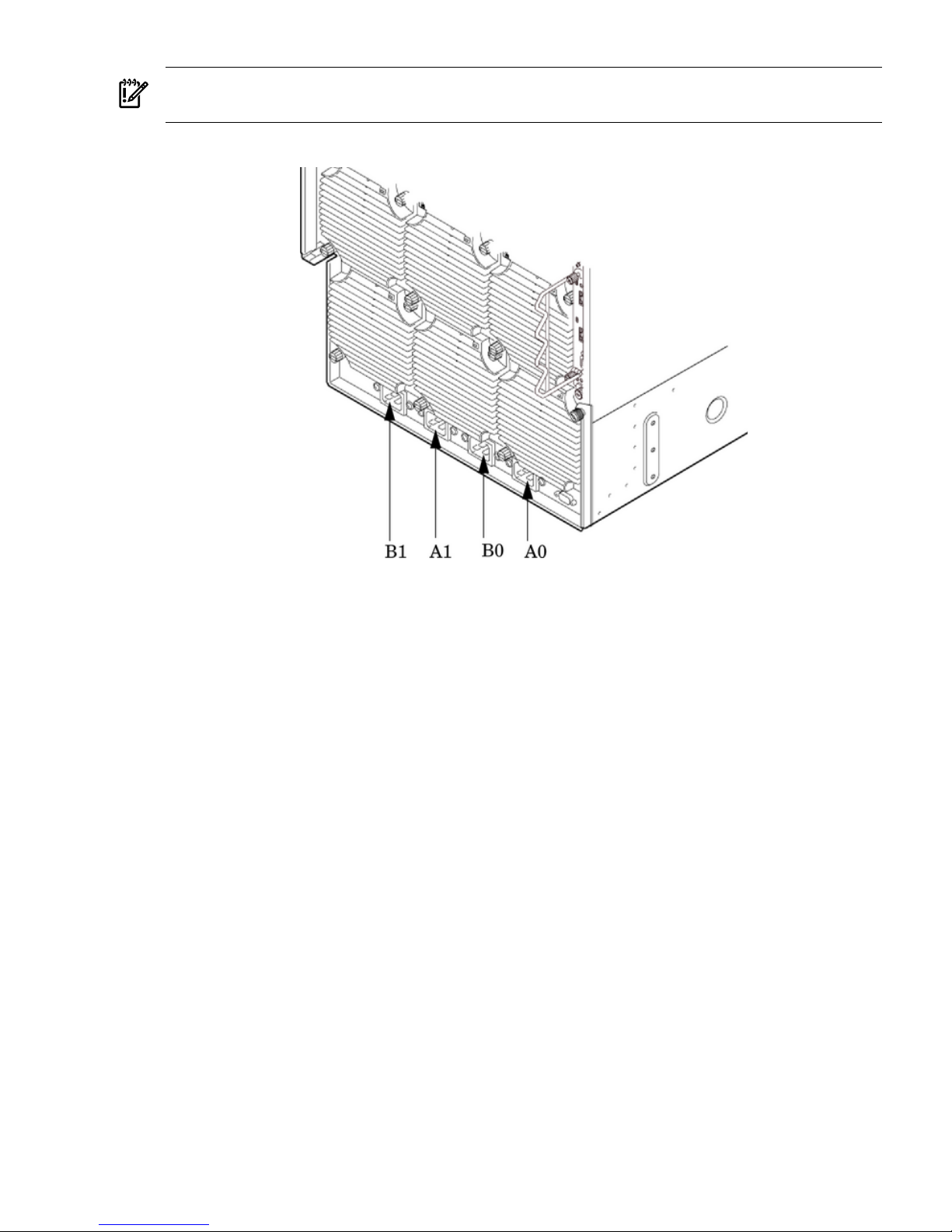
IMPORTANT: When running the server with a single power source, you must use A0 and A1.
Selecting redundant power requires all four power cords connected to A0–A1–B0–B1.
Figure 2-26 AC Power Input Labeling
The power distribution for the bulk power supplies is as follows:
• A0 input provides power to BPS 0, BPS 1, and BPS 2
• A1 input provides power to BPS 3, BPS 4, and BPS 5
• B0 input provides power to BPS 0, BPS 1, and BPS 2
• B1 input provides power to BPS 3, BPS 4, and BPS 5
For information on how input power cords supply power to each BPS, see Figure 2-27.
Cabling and Powering On the Server 67
Page 68
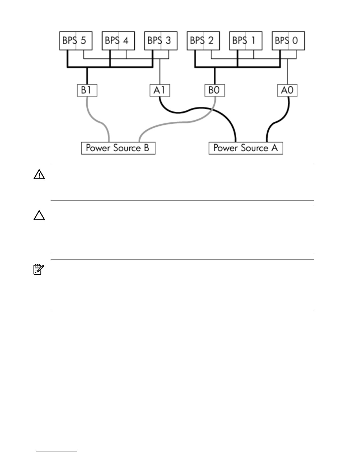
Figure 2-27 Distribution of Input Power for Each Bulk Power Supply
WARNING! Voltage is present at various locations within the server whenever a power source
is connected. This voltage is present even when the main power switch is in the off position. To
completely remove power, all power cords must be removed from the server. Failure to observe
this warning could result in personal injury or damage to equipment.
CAUTION: Do not route data and power cables together in the same cable management arm.
Do not route data and power cables in parallel paths in close proximity to each other. The
suggested minimum distance between the data and power cables is 3 inches (7.62 cm).
The power cord has current flowing through it, which creates a magnetic field. The potential to
induce electromagnetic interference in the data cables exists, which can cause data corruption.
NOTE: Label the AC power cords during the installation. One suggestion is to use tie wraps
that have the flag molded into the tie wrap. The flag can be labeled using the appropriate two
characters to represent the particular AC power input (for example, A0). Another suggestion
would be to use color coded plastic bands. Use one color to represent the first pair A0/A1 and
another color to represent the second pair B0/B1 (provided a second power source is available
at the customer site).
The server can accomodate a total of six BPSs. N+1 BPS capability describes the server having
adequate BPSs plus one additional module installed. If one BPS fails, adequate power will still
be supplied to the cell board(s) to keep the server partition(s) operational. Replace the failed BPS
promptly to restore N+1 functionality.
A minimum of two BPS are required to bring up a single cell board installed in the server. This
minimum configuration is not N+1 capable. See Table 2-5 (page 69) for BPS to cell board N+1
configurations.
The minimum N+1 configuration for the HP Integrity rx8640 server requires 2 cell boards and 4
BPS modules. The BPS modules must be installed per the following rules:
• BPS slots 0 and 1 must contain a BPS module for Grid A0–B0
• BPS slots 3 and 4 must contain a BPS module for Grid A1–B1
Installing the BPS modules per these rules ensures a balanced N+1 distribution of power to each
grid.
68 Installing the System
Page 69
IMPORTANT: The minimum supported N+1 BPS configuration for one cell board must have
BPS slots 0, 1, and 3 populated. When selecting a single power source, the power cords are
connected into A0 and A1.
Table 2-5 BPS-to-Cell Board Configuration to Achieve N+1
Number of Operational BPS Installed to Achieve N+1 FunctionalityNumber of Cell Boards Installed in the
Server
31
42
53
64
Applying Power to the Server
Observe the functionality of the server before attaching any LAN or serial cables, the system
console, or any peripherals to the server. Then, after applying an active AC power source to the
server, make the following observations at three different intervals, or points in time.
Interval One The power has just been applied to the server, but the front panel ON/OFF switch
is OFF. The front air intake fans will flash a dim red color, the bulk power supplies will flash
amber and an amber light is present on the hard disk drives.
Interval Two After the power has been plugged into the server for about 30 seconds, the standby
power turns on and the front intake fan LED indicators turn solid green. The BPS will flash green
and the amber light is still present on the hard disk drives. The front panel ON/OFF switch is
OFF at this interval. Housekeeping power is up at this point.
Interval Three With the ON/OFF switch on the front of the server set to ON, the intake fans
spin up and become noticeably audible, while the fan LED indicator remains solid green. The
BPS LED indicator turns a solid green, and the PCI backplane power supply LED indicators turn
solid green. The hard disk drive LED turns green briefly and then the LED turns OFF.
Installing The Line Cord Anchor (rack mounted servers)
The line cord anchor is attached to the rear of the server when rack mounted. It provides a method
to secure the line cords to the server preventing accidental removal of the cords from the server.
Four Cell Server Installation (rp8400, rp8420, rp8440, rx8620, rx8640)
There are holes pre-drilled, and captive nuts pre-installed, in the server chassis.
To install the line cord anchor
1. Align the line cord anchor thumbscrews with the corresponding captive nuts at the rear of
the chassis. Refer to Figure 2-28: “Four Cell Line Cord Anchor (rp8400, rp8420, rp8440,
rx8620, rx8640)”,
Cabling and Powering On the Server 69
Page 70
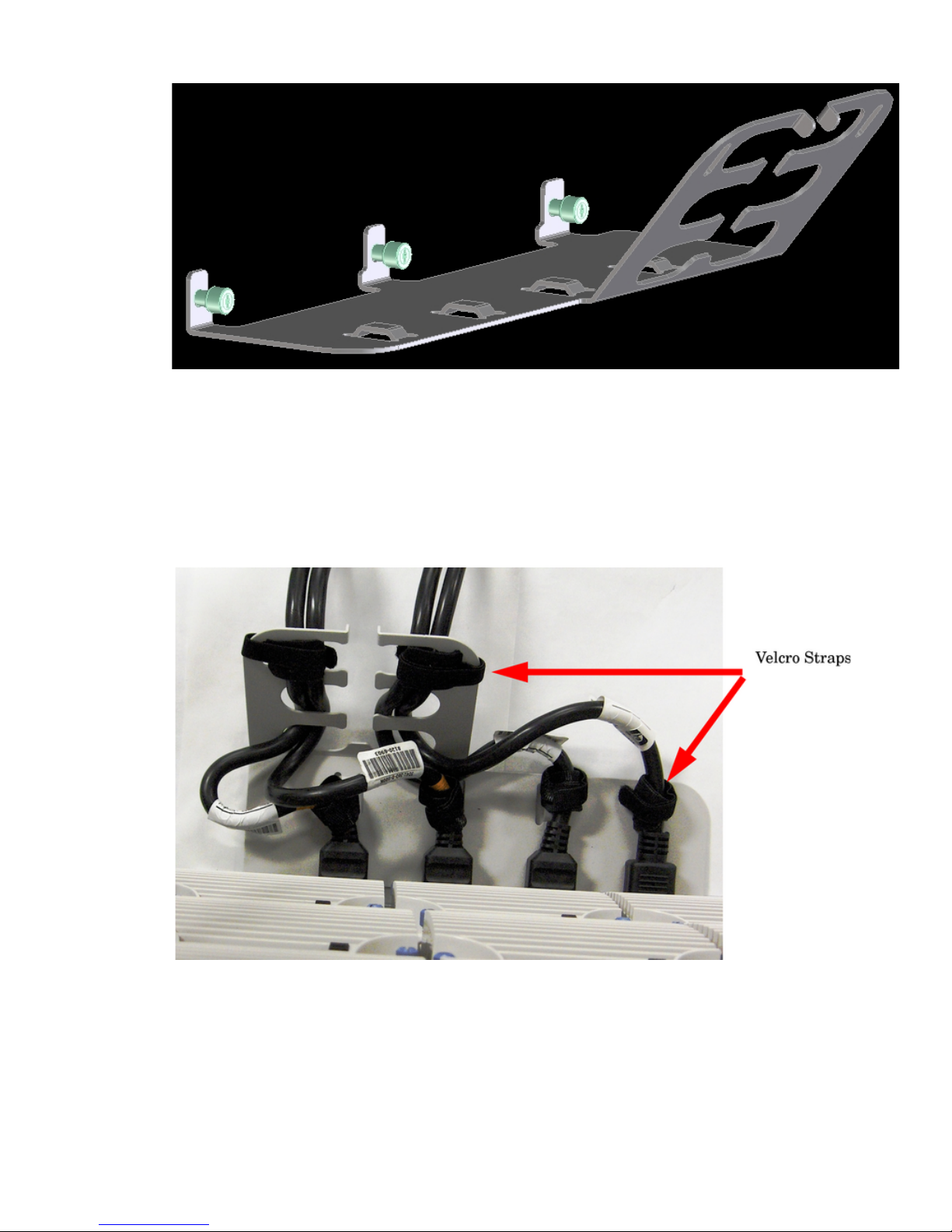
Figure 2-28 Four Cell Line Cord Anchor (rp8400, rp8420, rp8440, rx8620, rx8640)
2. Tighten the captive thumbscrews to secure the line cord anchor to the chassis.
3. Weave the power cables through the line cord anchor. Leave enough slack that the plugs
can be disconnected from the receptacles without removing the cords from the line cord
anchor
4. Use the supplied Velcro straps to attach the cords to the anchor. Refer to Figure 2-29: “Line
Cord Anchor and Velcro straps”,
Figure 2-29 Line Cord Anchor and Velcro straps
MP Core I/O Connections
Each HP server has at least one core I/O card installed. Each core I/O card has a management
processor (MP). If two core I/O cards are installed, this allows for two partitions to be configured
or enables core I/O redundancy in a single partition configuration. Each core I/O card is oriented
vertically and accessed from the back of the server.
Use the core I/O board to update firmware, access the console, turn partition power on and off,
and utilize other features of the system.
70 Installing the System
Page 71

External connections to the core I/O board include the following:
• One Ultra 320 (320 MB/sec) 68-pin SCSI port for connection to external SCSI devices by a
high-density cable interconnect (VHDCI) connector.
• One RJ-45 style 10Base-T/100Base-T/1000Base-T system LAN connector. This LAN uses
standby power and is active when AC is present and the front panel power switch is OFF.
• One RJ-45 style 10Base-T/100Base-T MP LAN connector. This LAN uses standby power and
is active when AC is present and the front panel power switch is OFF. This LAN is also
active when the front power switch is ON.
• One RS-232 connector which provides local console.
Internal connections for the core I/O board include the following:
• Two low voltage differential (LVD) internal SCSI buses for internal drives
• One single-ended (SE) internal SCSI bus for internal media.
Setting Up the Customer Engineer Tool (PC)
The CE Tool is usually a laptop. It allows communication with the management processor (MP)
in the server. The MP monitors the activity of either a one-partition or a multiple-partition
configuration.
During installation, communicating with the MP enables such tasks as:
• Verifying that the components are present and installed correctly
• Setting LAN IP addresses
• Shutting down cell board power
Establish communication with the MP by connecting the CE Tool to the local RS-232 port on the
core I/O card.
Setting CE Tool Parameters
After powering on the CE Tool, ensure that the communications settings are as follows:
• 8/none (parity)
• 9600 baud
• None (Receive)
• None (Transmit)
If the CE Tool is a laptop using Reflection 1, check or change these communications settings
using the following procedure:
1. From the Reflection 1 Main screen, pull down the Connection menu and select Connection
Setup.
2. Select Serial Port.
3. Select Com1.
4. Check the settings and change, if required.
Go to More Settings to set Xon/Xoff. Click OK to close the More Settings window.
5. Click OK to close the Connection Setup window.
6. Pull down the Setup menu and select Terminal (under the Emulation tab).
7. Select the VT100 HP terminal type.
8. Click Apply.
This option is not highlighted if the terminal type you want is already selected.
9. Click OK.
Cabling and Powering On the Server 71
Page 72
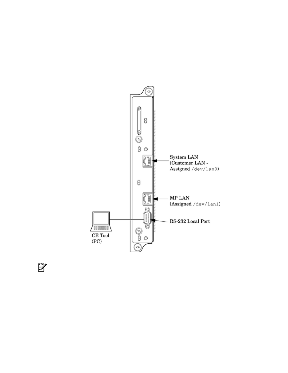
Connecting the CE Tool to the Local RS-232 Port on the MP
This connection enables direct communications with the MP. Only one window can be created
on the CE Tool to monitor the MP. When enabled, it provides direct access to the MP and to any
partition.
Use the following procedure to connect the CE Tool to the RS-232 Local port on the MP:
1. Connect one end of a null modem cable (9-pin to 9-pin) (Part Number 5182-4794) to the
RS-232 Local port on the core I/O card (the DB9 connector located at the bottom of the core
I/O card). Refer to Figure 2-30.
Figure 2-30 LAN and RS-232 Connectors on the Core I/O Board
NOTE: The ability to telnet to the MP LAN port is available once the MP is configured via
the RS-232 Local port.
2. Connect the other end of the RS-232 cable to the CE Tool.
Turning On Housekeeping Power and Logging In to the MP
After connecting the serial display device, the power to the server cabinet is ready to be supplied
to get a login prompt for the management processor (MP). Connecting the power cords allows
power to flow to the bulk power supplies (BPS) located at the front of the server cabinet, which
in turn provides housekeeping power (HKP).
Before powering up the server cabinet for the first time:
1. Verify that the AC voltage at the input source is within specifications for each server cabinet
being installed.
72 Installing the System
Page 73
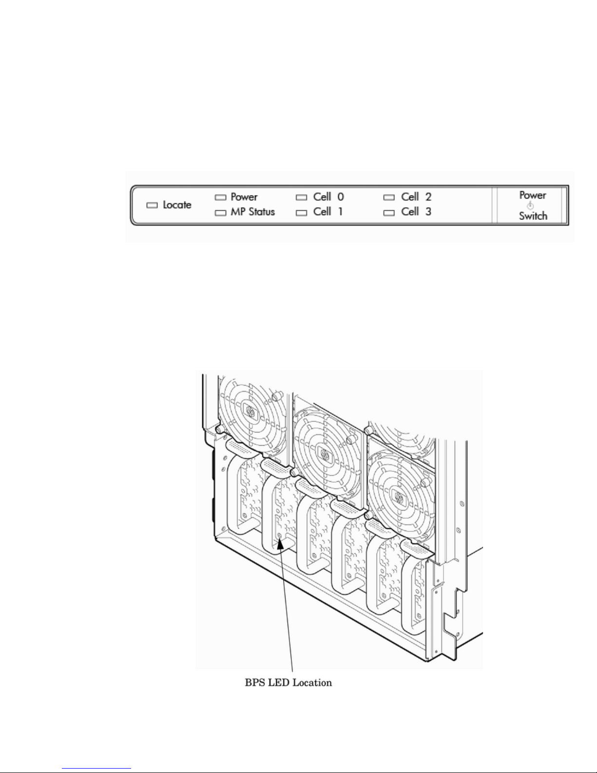
2. If not already done, power on the serial display device.
The preferred tool is the CE Tool running Reflection 1.
To power on the MP, set up a communications link, and log in to the MP:
1. Apply power to the server cabinet.
On the front of the server, the MP Status LED will illuminate yellow until the MP is booted
successfully. Once the MP is booted successfully, and no other cabinet faults exist, the LED
will change to solid green. Refer to Figure 2-31.
Figure 2-31 Front Panel Display
2. Check the bulk power supply (BPS) LED for each BPS. Refer to Figure 2-32 for the LED
location.
When on, the breakers distribute power to the BPS. AC power is present at the BPS:
• When power is first applied. The BPS LEDs will flash amber.
• After 30 seconds have elapsed. The flashing amber BPS LED for each BPS becomes a
flashing green LED.
Figure 2-32 BPS LED Location
Cabling and Powering On the Server 73
Page 74
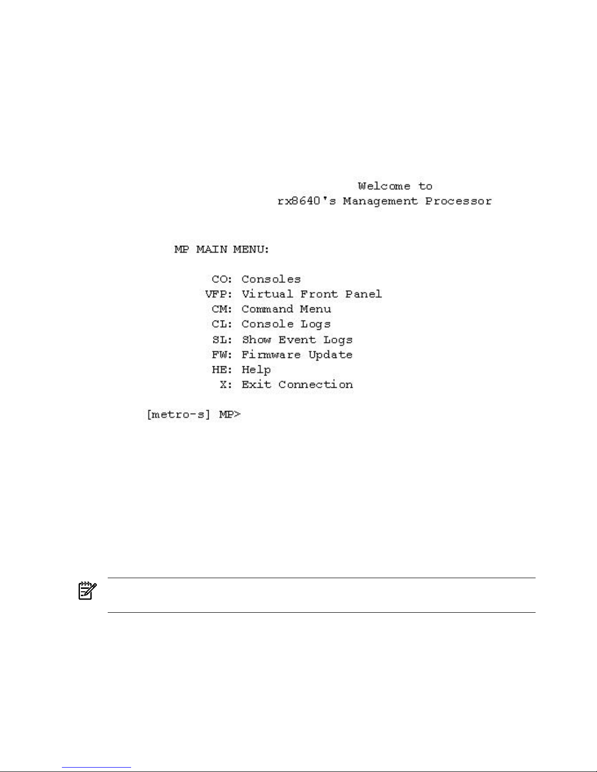
3. Log in to the MP:
1. Enter Admin at the login prompt. (This term is case-sensitive.)
It takes a few moments for the MP> prompt to appear. If the MP> prompt does not
appear, verify that the laptop serial device settings are correct: 8 bits, no parity, 9600
baud, and None for both Receive and Transmit. Then try again.
2. Enter Admin at the password prompt. (This term is case-sensitive.)
The MP Main Menu is displayed:
Figure 2-33 MP Main Menu
Configuring LAN Information for the MP
This section describes how to set and verify the server management processor (MP) LAN port
information. LAN information includes the MP network name, the MP IP address, the subnet
mask, and gateway address. This information is provided by the customer.
To set the MP LAN IP address:
1. At the MP Main Menu prompt (MP>), enter cm.
NOTE: If the Command Menu does not appear, enter q to return to the MP Main Menu,
then enter cm..
2. From the MP Command Menu prompt (MP>CM:), enter lc (for LAN configuration).
The screen displays the default values and asks if you want to modify them. It is a good
idea to write down the information or log it to a file, because it may be required for future
troubleshooting.
Enter lc and press the Return key. The lc command is displayed as shown in Figure 2-34.
74 Installing the System
Page 75
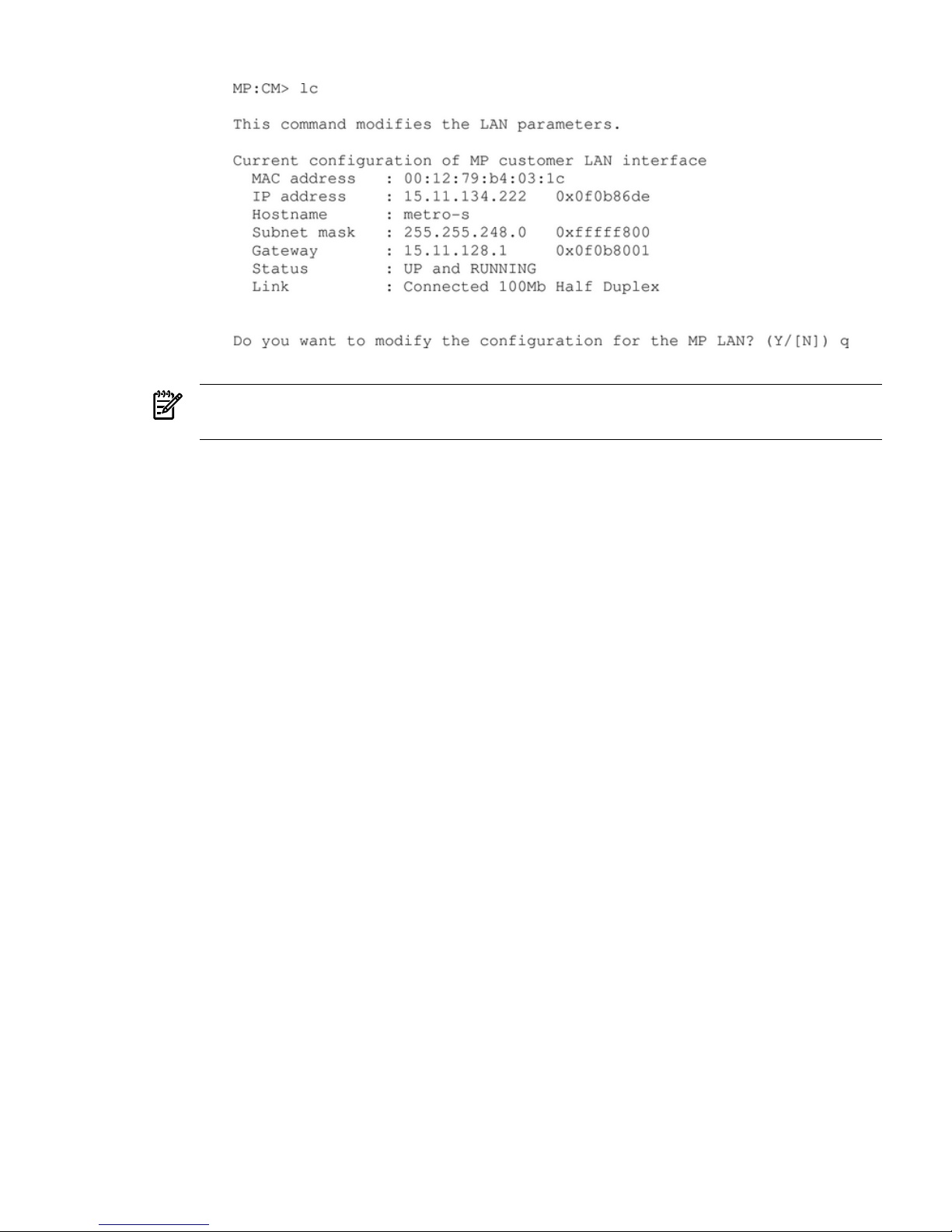
Figure 2-34 The lc Command Screen
3. NOTE: The value in the IP address field has been set at the factory. Obtain the LAN IP
address from the customer.
4. At the prompt, Do you want to modify the configuration for the customer
LAN?, enter Y.
The current IP address is shown; then the following prompt is displayed: Do you want
to modify it? (Y/[N])
5. Enter Y.
6. Enter the new IP address.
The customer provides this address for network interface 0.
7. Confirm the new address.
8. Enter the MP host name.
This is the host name for the customer LAN. The name can be up to 64 characters long and
can include alpha numerics, -dash (-), under score (_), period (.), or a space ( ). HP
recommends that the name be a derivative of the complex name, for example, Acme.com_MP.
9. Enter the LAN parameters for Subnet mask and Gateway address.
This information comes from the customer.
When this step is completed, the system will indicate that the parameters have been updated
and return to the MP Command Menu prompt (MP:CM>)
10. To check the LAN parameters and status, enter the ls command at the MP Command Menu
prompt (MP:CM>).
Cabling and Powering On the Server 75
Page 76
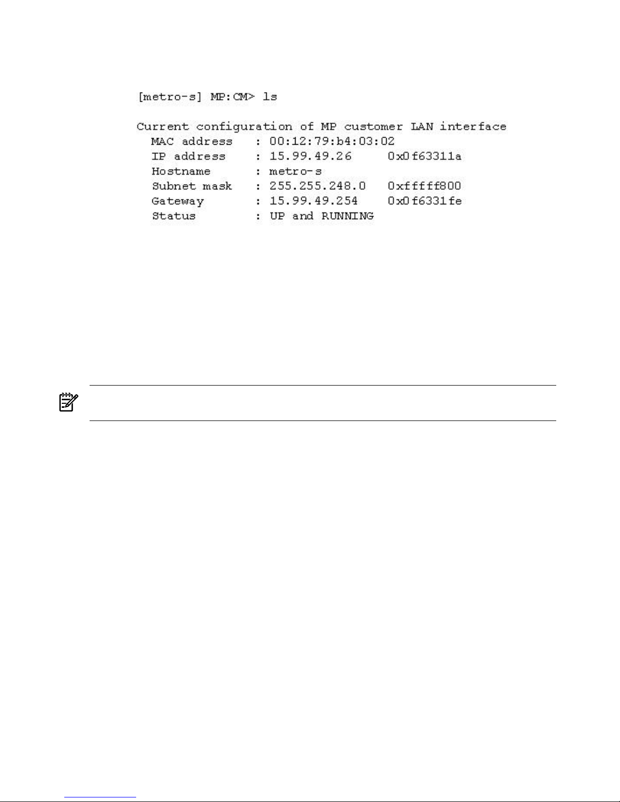
11. A screen similar to Figure 2-35 will display allowing verification of the settings.
Figure 2-35 The ls Command Screen
To return to the MP Main menu, enter ma.
To exit the MP, enter x at the MP Main Menu.
Accessing the Management Processor via a Web Browser
Web browser access is an embedded feature of the management processor (MP). The Web browser
enables access to the server via the LAN port on the core I/O card. MP configuration must be
done from an ASCII console.
NOTE: The MP has a separate LAN port from the system LAN port. It requires a separate LAN
drop, IP address, and networking information from that of the port used by HP-UX.
Before starting this procedure, gather the following information:
• IP address for the MP LAN
• Subnet mask
• Gateway address
• Host name (this is used when messages are logged or printed)
To configure the LAN port for a Web browser, perform the following steps:
1. Connect to the MP using a serial connection.
2. Configure the MP LAN. See “Configuring LAN Information for the MP”.
3. Type cmto enter the Command Menu.
4. Type sa at the MP:CM> prompt to display and set MP remote access.
76 Installing the System
Page 77
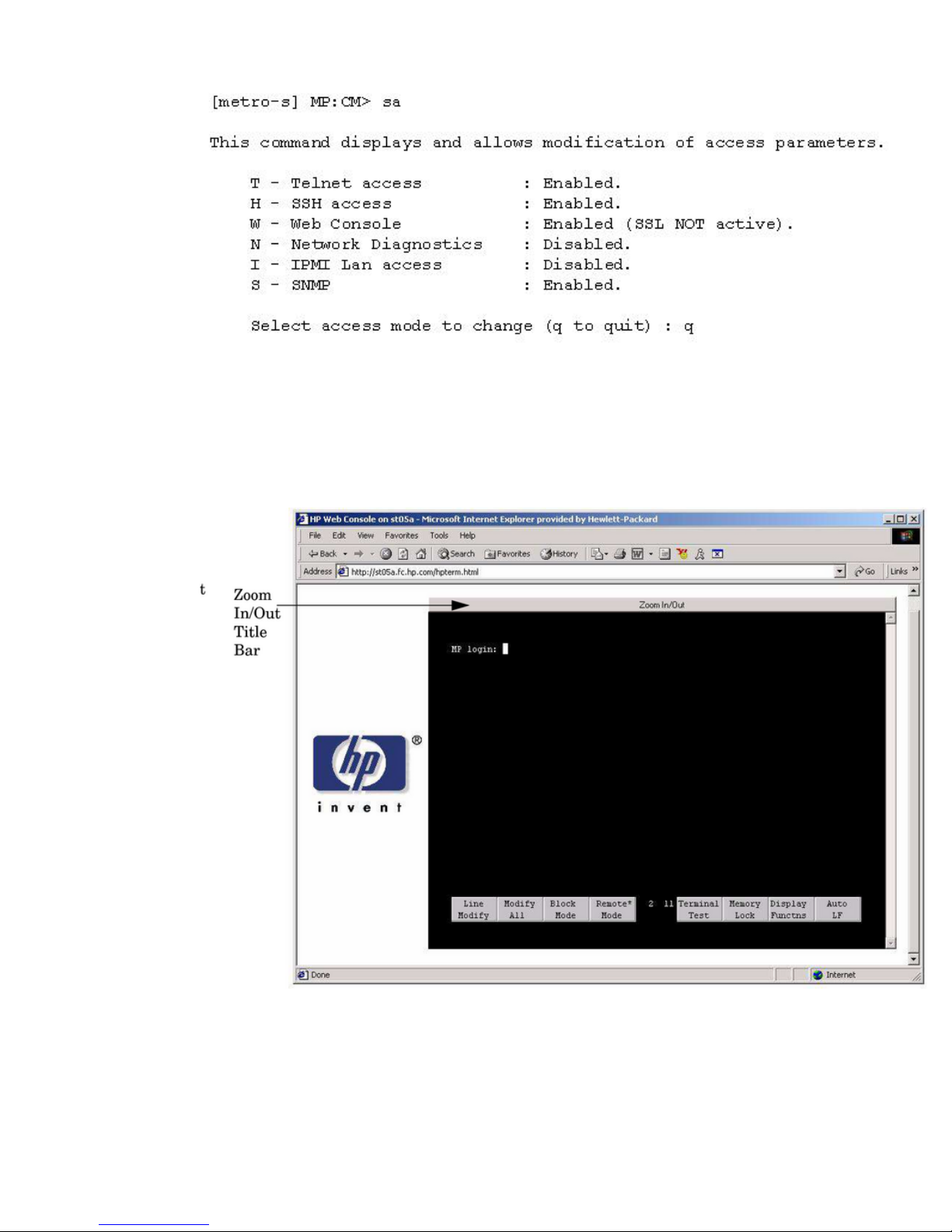
Figure 2-36 Example sa Command
5. Launch a Web browser on the same subnet using the IP address for the MP LAN port.
6. Click anywhere on the Zoom In/Out title bar (Figure 2-37) to generate a full screen MP
window.
Figure 2-37 Browser Window
7. Select the emulation type you want to use.
8. Log in to the MP when the login window appears.
Access to the MP via a Web browser is now possible.
Cabling and Powering On the Server 77
Page 78
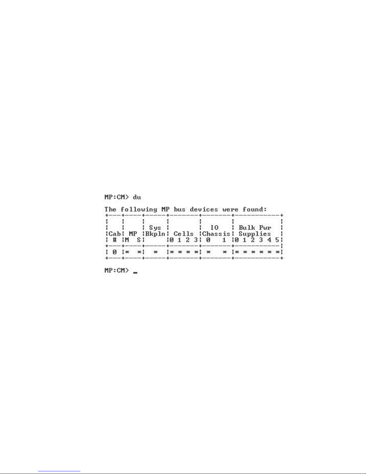
Verifying the Presence of the Cell Boards
To perform this activity, either connect to the management processor (MP) over the customer
console or connect the CE Tool (laptop) to the RS-232 Local port on the MP.
After logging in to the MP, verify that the MP detects the presence of all the cells installed in the
server cabinet. It is important for the MP to detect the cell boards. If it does not, the partitions
will not boot.
To determine if the MP detects the cell boards:
1. At the MP prompt, enter cm.
This displays the Command Menu. Among other things, the Command Menu enables you
to view or modify the configuration and to look at utilities controlled by the MP.
To look at a list of the commands available, enter he.. You might have to press Enterto see
more than one screen of commands. Use the Pg Up and Pg Down keys to view the previous
or next screen of commands. To exit the Help Menu, enter q.
2. From the command prompt (MP:CM>), enter du.
The du command displays the MP Bus topology. A screen similar to the one in Figure 2-38
is displayed.
Figure 2-38 The du Command Screen
The column marked MP will contain an asterisk (*)
3. Verify that there is an asterisk (*) for each of the cells installed in the server cabinet by
comparing what is in the Cells column with the cells physically located inside the server
cabinet.
Figure 2-38 shows that cells are installed in all the slots in cabinet 0, indicating that the server
cabinet, contains cells physically located in all the slots.
System Console Selection
Each operating system requires that the correct console type be selected from the firmware
selection menu. The following section describes how to determine the correct console device.
If an operating system is being installed or the system configuration is being changed the system
console setting must be checked to ensure it matches the hardware and OS. Not checking the
console selection can result in the system using an unexpected device as a console, which can
appear as a system hang when booting.
78 Installing the System
Page 79
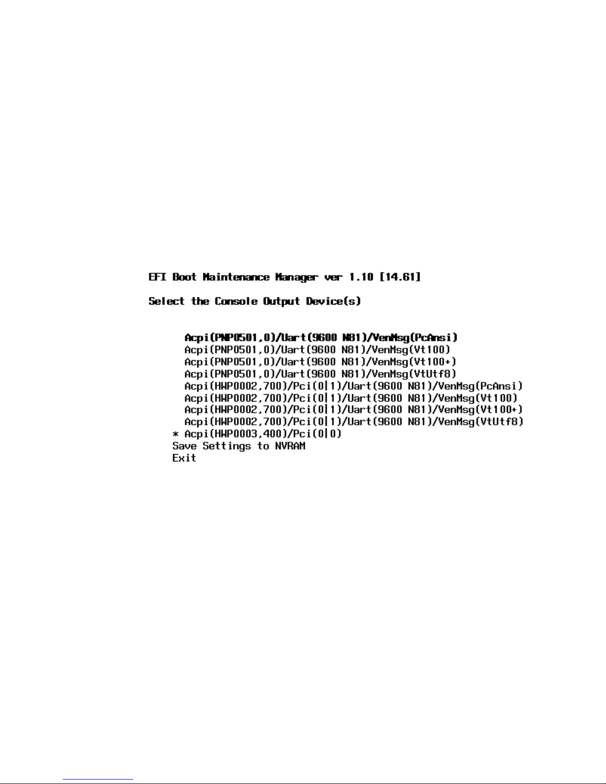
1. Determine the console you want to use.
Depending on your operating system and your hardware you can select one of two possible
devices as your system console. The possibilities are:
• Management Processor (MP) Serial Port
• VGA device
2. Select the appropriate console device (deselect unused devices):
a. Choose the “Boot option maintenance menu” choice from the main Boot Manager Menu.
b. Select the Console Output, Input or Error devices menu item for the device type you
are modifying:
• “Select Active Console Output Devices”
• “Select Active Console Input Devices”
• “Select Active Console Error Devices”
c. Available devices will be displayed for each menu selection. Figure 2-21 shows a typical
output of selecting the Console Output Devices menu.
Figure 2-39 Console Output Device menu
d. Choose the correct device for your system and deselect others. See “Interface Differences
Between Itanium-based Systems” for details about choosing the appropriate device.
e. Select Save Settings to NVRAMand then Exit to complete the change.
f. A system reset is required for the changes to take effect.
VGA Consoles
Any device that has a PCI section in its path and does not have a UART section will be a VGA
device. If you require a VGA console, choose the device and unmark all others. Figure 2-21 shows
that a VGA device is selected as the console.
Interface Differences Between Itanium-based Systems
Each Itanium-based system has a similar interface with minor differences. Some devices may
not be available on all systems depending on system design or installed options.
Other Console Types
Any device that has a UART section but no PCI section is a system serial port. To use the system
serial port (if available) as your console device, select the system serial device entry that matches
your console type(PcAnsi, Vt100, Vt100+, VtUtf8) and deselect everything else.
Cabling and Powering On the Server 79
Page 80

If you choose either a system or MP serial port HP recommends that you use a vt100+ capable
terminal device.
Additional Notes on Console Selection
Each Operating System makes decisions based on the EFI Boot Maintenance Manager menu’s
Select Active Console selections to determine where to send its output. If incorrect console devices
are chosen the OS may fail to boot or will boot with output directed to the wrong location.
Therefore, any time new potential console devices are added to the system or anytime NVRAM
on the system is cleared console selections should be reviewed to ensure that they are correct.
Configuring AC Line Status
The MP utilities can detect if power is applied to each of the AC input cords for the server, by
sampling the status of the bulk power supplies. During installation, use the following procedure
to check the configuration for the AC line status and configure it to match the customer’s
environment.
Selecting the single grid option directs the MP utilities to sense locations A0 and A1 for active
power. Selecting the dual grid option directs the MP utilities to sense active power at locations
A0–A1–B0–B1.
1. At the MP prompt, enter cm. This will display the Command Menu and enable you to view
and configure various utilities controlled by the MP.
2. From the command prompt (MP:CM>), enter pwrgrd. The pwrgrd command displays the
current power configuration. This command can also be used to change the power grid
configuration. A screen similar to the one in Figure 2-40 is displayed.
Figure 2-40 The pwrgrd Command Screen
3. Verify that the power grid configuration is correct by examining the output from the pwrgrd
command. The preceding power configuration indicates that the grid serving A0–A1 has
been configured.
4. To change the configuration, select the proper response and enter the appropriate numeric
value when Select Option: displays on the screen. If no change is desired, enter q and
press the Enter key. After the value has been entered, the MP will respond and indicate that
the change has taken effect.
Booting the Server
Power on the server either by pressing the power switch on the front panel or by using the PE
command to power on the cabinet or complex at the management processor Command Menu.
80 Installing the System
Page 81

If you are using a LAN crossover cable with the laptop, review server activity for each partition
configured while the server powers on and boots. You can open Windows for the complex and
for each partition. HP recommends that at least two windows be opened:
1. A window showing all activity in the complex. Following the installation procedure in this
document causes a window to be open at startup.
To display activity for the complex:
1. Open a separate Reflection window and connect to the MP.
2. From the MP Main Menu, select the VFP command with the s option.
2. A window showing activity for a single partition.
To display activity for each partition as it powers on:
1. Open a separate Reflection window and connect to the MP.
2. Select the VFP command and select the desired partition to view.
There should be no activity on the screen at this point in the installation process.
NOTE: You cannot open more than one window using a serial display device.
To power on the server:
1. If a Server Expansion Unit is attached to the server, press both the server power switch and
the SEU power switch. Alternatively, at the MP:CM> prompt, use the PE X command to
power on the complex, or the PE T command for each cabinet. The following events occur:
• Power is applied to the server.
• Processor-dependent code (PDC) starts to run on each cell.
• The cell self-test executes.
• Hardware initializes for the server.
• Console communication is established.
2. After the cell has joined the partition or after boot is blocked (BIB) is displayed at the Virtual
Front Panel (VFP), return to the MP Main Menu by pressing Ctrl+B.
3. Enter co to enter console mode.
4. Enter the partition number of the partition to boot.
5. Press Enter.
Selecting a Boot Partition Using the MP
At this point in the installation process, the hardware is set up, the MP is connected to the LAN,
the AC and DC power have been turned on, and the self-test is completed. Now the configuration
can be verified.
After the DC power on and the self-test is complete, use the MP to select a boot partition.
1. From the MP Main Menu, enter cm.
2. From the MP Command Menu, enter bo.
3. Select the partition to boot. Partitions can be booted in any order.
4. Return to the MP Main Menu by entering ma from the MP Command Menu.
5. Enter the console by typing co at the MP Main Menu.
Exit the MP to return automatically to the Extensible Firmware Interface (EFI) Shell menu.
Cabling and Powering On the Server 81
Page 82

Verifying the System Configuration Using the EFI Shell
From the EFI main menu, enter the POSSE shell by entering co. Typing help will list all the
command categories available in the shell:
• configuration -- goes to the configuration menu, where system configuration can be reset,
configured or viewed.
• memory -- memory related commands.
Once the parameters have been verified, enter x to return to the EFI Main Menu.
Booting HP-UX Using the EFI Shell
If the Instant Ignition was ordered, HP-UX will have been installed in the factory at the Primary
Path address. If HP-UX is at a path other than the Primary Path, do the following:
1. Type cmto enter the Command Menu from the Main Menu.
2. MP:CM> bo This command boots the selected partition.
Select a partition to boot:
3. Return to the Main Menu: MP:CM> ma
4. From the Main Menu, go to the Consoles Menu: MP> co.
Select a partition number.
5. Return to the Main Menu by pressing Ctrl+B.
6. At the EFI Shell prompt, select the file system to boot. Generally this is fs0.
Shell> fso:
7. At the fs0 prompt, type hpux to boot the HP-UX operating system:
fso:\> hpux
NOTE: If the partition fails to boot or if the server was shipped without Instant Ignition, booting
from a DVD that contains the operating system and other necessary software might be required.
Adding Processors with Instant Capacity
The Instant Capacity program provides access to additional CPU resources beyond the amount
that was purchased for the server. This provides the ability to activate additional CPU power
for unexpected growth and unexpected spikes in workloads. Internally, Instant Capacity systems
physically have more CPUs, called Instant Capacity CPUs, than the number of CPUs actually
purchased. These Instant Capacity CPUs reside in the purchased system, but they belong to HP
and therefore are HP assets. A nominal “Right-To-Access Fee” is paid to HP for each Instant
Capacity processor in the system. At any time, any number of Instant Capacity CPUs can be
“activated.” Activating an Instant Capacity CPU automatically and instantaneously transforms
the Instant Capacity CPU into an instantly ordered and fulfilled CPU upgrade that requires
payment. After the Instant Capacity CPU is activated and paid for, it is no longer an Instant
Capacity CPU, but is now an ordered and delivered CPU upgrade for the system.
The most current information on installing, configuring, and troubleshooting Instant Capacity
is available at http://docs.hp.com.
82 Installing the System
Page 83
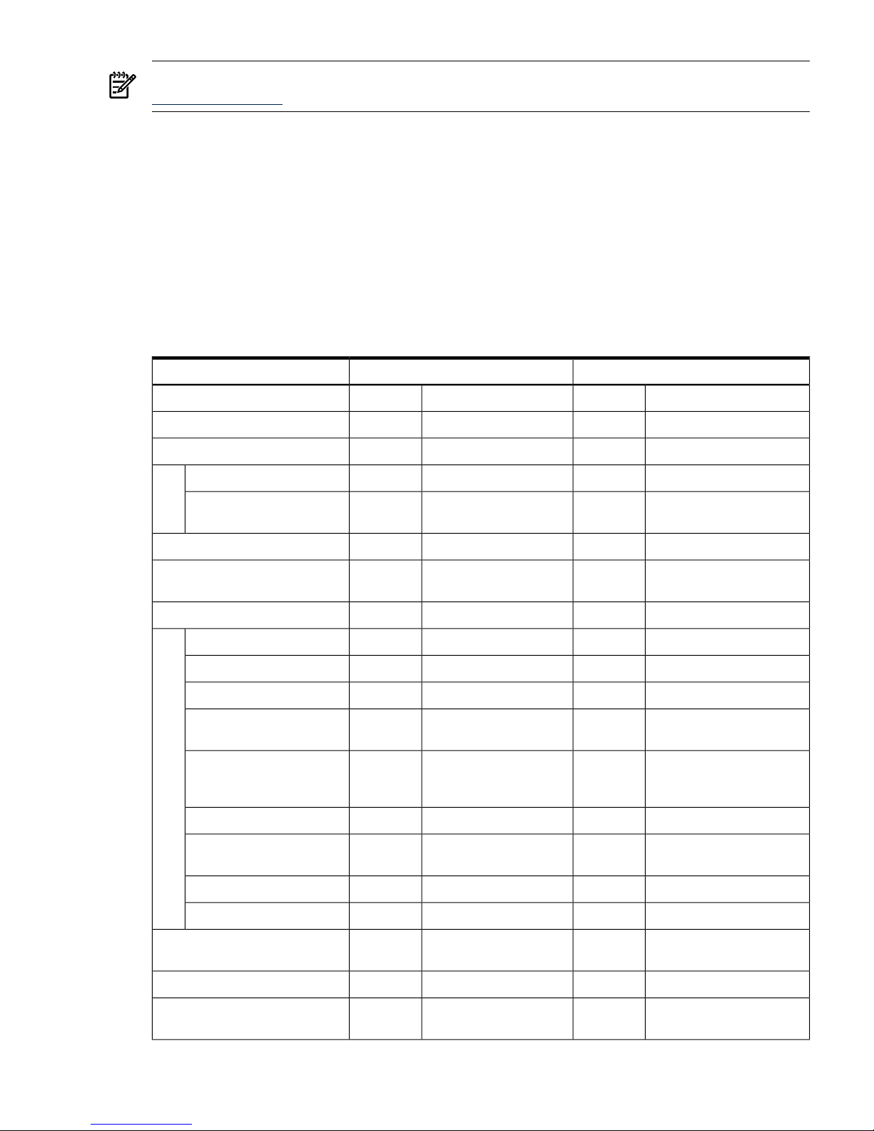
NOTE: Ensure that the customer is aware of the Instant Capacity email requirements. See
http://docs.hp.com for further details.
Installation Checklist
The checklist in Table 2-6 is an installation aid. Use it only after you have installed several systems
by following the detailed procedures described in the body of this document. This checklist is a
compilation of the tasks described in this document, and is organized as follows:
Procedures The procedures outlined in this document in order.
In-process The portion of the checklist that allows you to comment on the current status
of a procedure.
Completed The final check to ensure that a step has been completed and comments.
Major tasks are in bold type, subtasks are indented.
Table 2-6 Factory-Integrated Installation Checklist
CompletedIn-processProcedure
CommentsInitialsCommentsInitials
Obtain LAN information
Verify site preparation
Site grounding verified
Power requirements
verified
Check inventory
Inspect shipping containers for
damage
Unpack cabinet
Allow proper clearance
Cut polystrap bands
Remove cardboard top cap
Remove corrugated wrap
from the pallet
Remove four bolts holding
down the ramps and
remove the ramps
Remove antistatic bag
Check for damage (exterior
and interior)
Position ramps
Roll cabinet off ramp
Unpack the peripheral cabinet
(if ordered)
Unpack other equipment
Remove and dispose of
packaging material
Cabling and Powering On the Server 83
Page 84
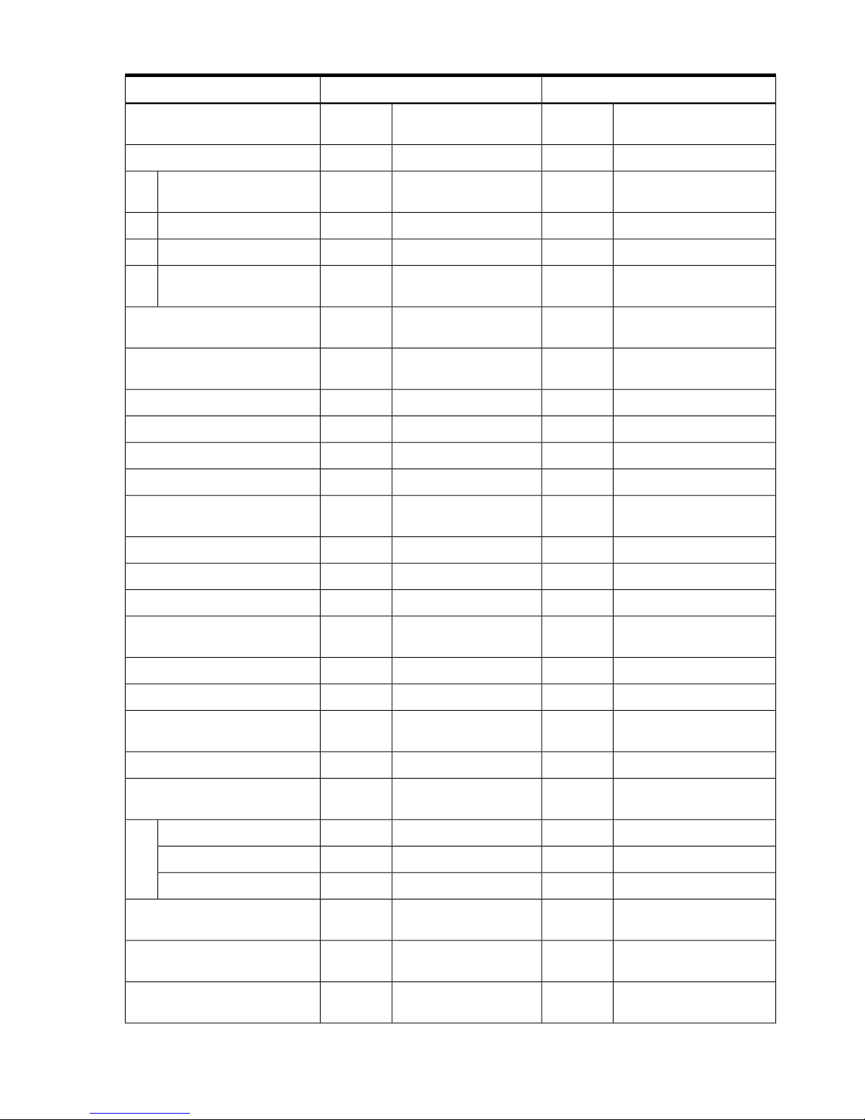
Table 2-6 Factory-Integrated Installation Checklist (continued)
CompletedIn-processProcedure
Move cabinet and equipment to
computer room
Move cabinet into final position
Position cabinet next to each
other (approx. 1/2 inch)
Adjust leveling feet
Install anti tip plates
Inspect cables for proper
installation
Set up CE tool and connect to
Remote RS-232 port on MP
Apply power to cabinet
(Housekeeping)
Check power to BPSs
Log in to MP
Set LAN IP address on MP
Connect customer console
Set up network on customer
console
Verify LAN connection
Verify presence of cells
Power on cabinet (48 V)
Verify system configuration and
set boot parameters
Set automatic system restart
Boot partitions
Configure remote login (if
required).
Verify remote link (if required).
Install non-factory, integrated
I/O cards (if required)
Select PCI card slot
Install PCI card
Verify installation
Route cables using the cable
management arm
Install other peripherals (if
required)
Perform visual inspection and
complete installation
84 Installing the System
Page 85
Table 2-6 Factory-Integrated Installation Checklist (continued)
CompletedIn-processProcedure
Set up network services (if
required)
Enable Instant Capacity (if
available)
Final inspection of circuit boards
Final inspection of cabling
Area cleaned and debris and
packing materials disposed of
Tools accounted for
Parts and other items disposed
of
Make entry in Gold Book
(recommended)
Customer acceptance and signoff
(if required)
Cabling and Powering On the Server 85
 Loading...