

Page 1

HP 9000
Series 700 and 800
Computers
Using the HP DTC Manager/UX
Page 2

Page 3

Notice
Hewlett-Packard makes no warranty of any kind with regard to this material,
including, but not limited to, the implied warranties of merchantability and
fitness for a particular purpose. Hewlett-Packard shall not be liable for errors
contained herein or for incidental or consequential damages in connection with the
furnishing, performance, or use of this material.
Hewlett-Packard assumes no responsibility for the use or reliability of its software
on equipment that is not furnished by Hewlett-Packard.
© Copyright 1992, 1993, 1995, 1997 Hewlett-Packard Company.
This document contains proprietary information, which is protected by copyright.
All rights are reserved. No part of this document may be photocopied, reproduced,
or translated to another language without the prior written consent of HewlettPackard Company. The information contained in this document is subject to change
without notice.
UNIX is a registered trademark in the United States and other countries, licensed exclusively
through X/Open Company Limited.
RESTRICTED RIGHTS LEGEND
Use, duplication or disclosure by the U.S. Government is subject to restrictions as
set forth in subparagraph (c)(1)(ii) of the Rights in Technical Data and Computer
Software clause at DFARS 252.227-7013 for DoD agencies, and subparagraphs
(c)(1) and (c)(2) of the Commercial Computer Software Restricted Rights clause at
FAR 52.227-19 for other agencies.
Hewlett-Packard Co.
19420 Homestead Rd.
Cupertino, CA 95014 U.S.A.
iii
Page 4

Printing history
Note that many product updates and fixes do not require manual changes and,
conversely, manual corrections may be done without accompanying product
changes. Therefore, do not expect a one-to-one correspondence between product
updates and manual updates.
Edition 1. . . . . . . . . . . . . . . . . . . . . . . . . . . . . . . . . . . . . . . . . . . . . . . . . . May 1992
Edition 2. . . . . . . . . . . . . . . . . . . . . . . . . . . . . . . . . . . . . . . . . . . . . . February 1993
Edition 3. . . . . . . . . . . . . . . . . . . . . . . . . . . . . . . . . . . . . . . . . . . . . September 1993
Edition 4. . . . . . . . . . . . . . . . . . . . . . . . . . . . . . . . . . . . . . . . . . . . . . .February 1995
Edition 5. . . . . . . . . . . . . . . . . . . . . . . . . . . . . . . . . . . . . . . . . . . . . . . . . . May 1995
Edition 6. . . . . . . . . . . . . . . . . . . . . . . . . . . . . . . . . . . . . . . . . . . . . . . . . . May 1997
Edition 6 is released with software versions A.14.4A.010 (for HP-UX version
10.10), A.14.4A.020 (for HP-UX version 10.20) and A.14.4A.030 (for HP-UX
version 10.30).
Comments Comments on this manual can be sent to the following address
The Manager
Learning Products/Usability
Enterprise Networking & Security Division
Hewlett-Packard France
5, Avenue Raymond Chanas - Eybens
38053 GRENOBLE
France
You can also send comments to the following e-mail address, quoting the customer
order number, the HP manufacturing part number and edition number:
iv
Page 5

Contents
Purpose of this manual. . . . . . . . . . . . . . . . . . . . . . . . . . . . . . . . . . . . . . . . . . . . . . . . . . . . .xi
Intended audience . . . . . . . . . . . . . . . . . . . . . . . . . . . . . . . . . . . . . . . . . . . . . . . . . . . . . . . .xi
Prerequisites. . . . . . . . . . . . . . . . . . . . . . . . . . . . . . . . . . . . . . . . . . . . . . . . . . . . . . . . . . . . xii
Related HP Documentation . . . . . . . . . . . . . . . . . . . . . . . . . . . . . . . . . . . . . . . . . . . . . . . . xii
1 Introduction to DTC Manager/UX. . . . . . . . . . . . . . . . . . . . . . . . . . . . . . . . . . . . . . . . . 15
DTC overview . . . . . . . . . . . . . . . . . . . . . . . . . . . . . . . . . . . . . . . . . . . . . . . . . . . . . . . . . .15
DTC Manager/UX overview . . . . . . . . . . . . . . . . . . . . . . . . . . . . . . . . . . . . . . . . . . . . . . . 16
DTC Manager/UX commands . . . . . . . . . . . . . . . . . . . . . . . . . . . . . . . . . . . . . . . . . . . . 17
Required daemons . . . . . . . . . . . . . . . . . . . . . . . . . . . . . . . . . . . . . . . . . . . . . . . . . . . . . 18
DTCs that can be managed by DTC Manager/UX . . . . . . . . . . . . . . . . . . . . . . . . . . . . 18
IP addresses . . . . . . . . . . . . . . . . . . . . . . . . . . . . . . . . . . . . . . . . . . . . . . . . . . . . . . . . . . . . 20
Special DTC terminology . . . . . . . . . . . . . . . . . . . . . . . . . . . . . . . . . . . . . . . . . . . . . . . . . 21
2 Before installing DTC Manager/UX. . . . . . . . . . . . . . . . . . . . . . . . . . . . . . . . . . . . . . . . 23
Hardware requirements . . . . . . . . . . . . . . . . . . . . . . . . . . . . . . . . . . . . . . . . . . . . . . . . . 23
Software requirements . . . . . . . . . . . . . . . . . . . . . . . . . . . . . . . . . . . . . . . . . . . . . . . . . . 24
Supported terminals . . . . . . . . . . . . . . . . . . . . . . . . . . . . . . . . . . . . . . . . . . . . . . . . . . . . 24
3 Installing DTC Manager/UX. . . . . . . . . . . . . . . . . . . . . . . . . . . . . . . . . . . . . . . . . . . . . . 25
Installing DTC Manager/UX with HP-UX 10.x . . . . . . . . . . . . . . . . . . . . . . . . . . . . . . . . 26
Installing the software . . . . . . . . . . . . . . . . . . . . . . . . . . . . . . . . . . . . . . . . . . . . . . . . . . 26
Preparing the environment for the required daemon processes . . . . . . . . . . . . . . . . . . . 28
Running the daemons without rebooting . . . . . . . . . . . . . . . . . . . . . . . . . . . . . . . . . . . . 29
Verifying that the daemons are running. . . . . . . . . . . . . . . . . . . . . . . . . . . . . . . . . . . . . 30
Verifying the software version. . . . . . . . . . . . . . . . . . . . . . . . . . . . . . . . . . . . . . . . . . . . 32
If you don’t want DTC Manager to be started automatically . . . . . . . . . . . . . . . . . . . . 32
Removing DTC Manager/UX . . . . . . . . . . . . . . . . . . . . . . . . . . . . . . . . . . . . . . . . . . . . 32
Stopping the daemons . . . . . . . . . . . . . . . . . . . . . . . . . . . . . . . . . . . . . . . . . . . . . . . . . . 32
Other file-handling features . . . . . . . . . . . . . . . . . . . . . . . . . . . . . . . . . . . . . . . . . . . . . . 32
Installing DTC Manager/UX with HP-UX 9.x . . . . . . . . . . . . . . . . . . . . . . . . . . . . . . . . . 33
Installing the software . . . . . . . . . . . . . . . . . . . . . . . . . . . . . . . . . . . . . . . . . . . . . . . . . . 33
Verifying the installation . . . . . . . . . . . . . . . . . . . . . . . . . . . . . . . . . . . . . . . . . . . . . . . . 34
Verifying that the daemons are running. . . . . . . . . . . . . . . . . . . . . . . . . . . . . . . . . . . . . 36
Verifying the software version. . . . . . . . . . . . . . . . . . . . . . . . . . . . . . . . . . . . . . . . . . . . 37
Managing DTC configuration files . . . . . . . . . . . . . . . . . . . . . . . . . . . . . . . . . . . . . . . . . . 38
5
Page 6

Contents
Automatic protection of configuration files. . . . . . . . . . . . . . . . . . . . . . . . . . . . . . . . . . 38
Automatic backup of DTC Manager files . . . . . . . . . . . . . . . . . . . . . . . . . . . . . . . . . . . 38
Automatic upgrade of DTC configuration files . . . . . . . . . . . . . . . . . . . . . . . . . . . . . . . 38
4 Using dtcconfig . . . . . . . . . . . . . . . . . . . . . . . . . . . . . . . . . . . . . . . . . . . . . . . . . . . . . . . . .39
Configuration guidelines . . . . . . . . . . . . . . . . . . . . . . . . . . . . . . . . . . . . . . . . . . . . . . . . 39
To start the dtcconfig utility. . . . . . . . . . . . . . . . . . . . . . . . . . . . . . . . . . . . . . . . . . . . . . . . 41
Using the dtcconfig menus. . . . . . . . . . . . . . . . . . . . . . . . . . . . . . . . . . . . . . . . . . . . . . . . . 42
The main menu. . . . . . . . . . . . . . . . . . . . . . . . . . . . . . . . . . . . . . . . . . . . . . . . . . . . . . . . . .43
Using the function keys . . . . . . . . . . . . . . . . . . . . . . . . . . . . . . . . . . . . . . . . . . . . . . . . . . . 44
Using the editing keys . . . . . . . . . . . . . . . . . . . . . . . . . . . . . . . . . . . . . . . . . . . . . . . . . . . . 45
Refreshing the screen. . . . . . . . . . . . . . . . . . . . . . . . . . . . . . . . . . . . . . . . . . . . . . . . . . . . . 45
Getting help . . . . . . . . . . . . . . . . . . . . . . . . . . . . . . . . . . . . . . . . . . . . . . . . . . . . . . . . . . . . 46
Exiting from dtcconfig. . . . . . . . . . . . . . . . . . . . . . . . . . . . . . . . . . . . . . . . . . . . . . . . . . . . 46
5 Adding DTCs . . . . . . . . . . . . . . . . . . . . . . . . . . . . . . . . . . . . . . . . . . . . . . . . . . . . . . . . . .47
Procedure overview . . . . . . . . . . . . . . . . . . . . . . . . . . . . . . . . . . . . . . . . . . . . . . . . . . . . . . 47
Adding a DTC to the configuration . . . . . . . . . . . . . . . . . . . . . . . . . . . . . . . . . . . . . . . . . . 48
Checking the terminal connections . . . . . . . . . . . . . . . . . . . . . . . . . . . . . . . . . . . . . . . . . . 50
Configuration parameter definitions . . . . . . . . . . . . . . . . . . . . . . . . . . . . . . . . . . . . . . . . . 50
6 Modifying DTCs with dtcconfig . . . . . . . . . . . . . . . . . . . . . . . . . . . . . . . . . . . . . . . . . . . 53
Modifying a DTC configuration . . . . . . . . . . . . . . . . . . . . . . . . . . . . . . . . . . . . . . . . . . . . 54
Using the Rear Panel Configuration screen. . . . . . . . . . . . . . . . . . . . . . . . . . . . . . . . . . . . 56
Entering values in the board and port fields. . . . . . . . . . . . . . . . . . . . . . . . . . . . . . . . . . 57
Rear panel configuration screen examples. . . . . . . . . . . . . . . . . . . . . . . . . . . . . . . . . . . . . 59
7 Configuring a DTC CPU/LAN or LAN board with dtcconfig. . . . . . . . . . . . . . . . . . . 61
Configuring CPU/LAN or LAN board parameters . . . . . . . . . . . . . . . . . . . . . . . . . . . . . . 62
Configuring LAN addresses. . . . . . . . . . . . . . . . . . . . . . . . . . . . . . . . . . . . . . . . . . . . . . . . 65
LAN address parameter definitions . . . . . . . . . . . . . . . . . . . . . . . . . . . . . . . . . . . . . . . . 66
Configuring global parameters. . . . . . . . . . . . . . . . . . . . . . . . . . . . . . . . . . . . . . . . . . . . . . 67
Global parameter definitions . . . . . . . . . . . . . . . . . . . . . . . . . . . . . . . . . . . . . . . . . . . . . 69
Configuring TCP parameters . . . . . . . . . . . . . . . . . . . . . . . . . . . . . . . . . . . . . . . . . . . . . . . 72
Configuring DNS/IP parameters . . . . . . . . . . . . . . . . . . . . . . . . . . . . . . . . . . . . . . . . . . . . 74
DNS parameter definitions. . . . . . . . . . . . . . . . . . . . . . . . . . . . . . . . . . . . . . . . . . . . . . . 75
IP Routing parameter definitions . . . . . . . . . . . . . . . . . . . . . . . . . . . . . . . . . . . . . . . . . . 76
Configuring SNMP parameters . . . . . . . . . . . . . . . . . . . . . . . . . . . . . . . . . . . . . . . . . . . . . 77
Configuring SNMP authorization filters . . . . . . . . . . . . . . . . . . . . . . . . . . . . . . . . . . . . . . 78
SNMP authorization filter parameter definitions. . . . . . . . . . . . . . . . . . . . . . . . . . . . . . 79
Configuring SNMP MIB data . . . . . . . . . . . . . . . . . . . . . . . . . . . . . . . . . . . . . . . . . . . . . . 80
SNMP parameter definitions . . . . . . . . . . . . . . . . . . . . . . . . . . . . . . . . . . . . . . . . . . . . . 81
Configuring DTC management protocol parameters. . . . . . . . . . . . . . . . . . . . . . . . . . . . . 82
6
Page 7

Contents
8 Configuring DTC ports with dtcconfig. . . . . . . . . . . . . . . . . . . . . . . . . . . . . . . . . . . . . . 85
Configuring the port type. . . . . . . . . . . . . . . . . . . . . . . . . . . . . . . . . . . . . . . . . . . . . . . . . . 85
Configuring terminal and printer ports . . . . . . . . . . . . . . . . . . . . . . . . . . . . . . . . . . . . . . . 87
Configurable port parameters. . . . . . . . . . . . . . . . . . . . . . . . . . . . . . . . . . . . . . . . . . . . . . . 88
Configuring a port . . . . . . . . . . . . . . . . . . . . . . . . . . . . . . . . . . . . . . . . . . . . . . . . . . . . . . .89
Configuring terminal and printer port parameters . . . . . . . . . . . . . . . . . . . . . . . . . . . . . . . 91
Terminal and printer port parameter definitions . . . . . . . . . . . . . . . . . . . . . . . . . . . . . . 93
Enabling port options. . . . . . . . . . . . . . . . . . . . . . . . . . . . . . . . . . . . . . . . . . . . . . . . . . . . . 99
Enable terminal or printer port options parameter definitions. . . . . . . . . . . . . . . . . . . 101
Configuring a DTC to enable a printer . . . . . . . . . . . . . . . . . . . . . . . . . . . . . . . . . . . . . . 104
Configuring a DTC port to be a printer port . . . . . . . . . . . . . . . . . . . . . . . . . . . . . . . . 105
DTC Device File Access utilities and Telnet port identification. . . . . . . . . . . . . . . . . 106
Using DDFA to create a device file name for the printer port. . . . . . . . . . . . . . . . . . . 107
Configuring a DTC printer for the HP-UX spooler . . . . . . . . . . . . . . . . . . . . . . . . . . . 109
Testing the printer configuration . . . . . . . . . . . . . . . . . . . . . . . . . . . . . . . . . . . . . . . . . 110
9 Other commands with dtcconfig. . . . . . . . . . . . . . . . . . . . . . . . . . . . . . . . . . . . . . . . . . 111
Modifying the default parameters . . . . . . . . . . . . . . . . . . . . . . . . . . . . . . . . . . . . . . . . . . 112
Deleting a DTC . . . . . . . . . . . . . . . . . . . . . . . . . . . . . . . . . . . . . . . . . . . . . . . . . . . . . . . . 116
Adding a board to a DTC. . . . . . . . . . . . . . . . . . . . . . . . . . . . . . . . . . . . . . . . . . . . . . . . . 117
Deleting a board from a DTC . . . . . . . . . . . . . . . . . . . . . . . . . . . . . . . . . . . . . . . . . . . . . 117
Copying and pasting configurations . . . . . . . . . . . . . . . . . . . . . . . . . . . . . . . . . . . . . . . . 118
What you can copy and paste. . . . . . . . . . . . . . . . . . . . . . . . . . . . . . . . . . . . . . . . . . . . 118
Copying and pasting a board or port . . . . . . . . . . . . . . . . . . . . . . . . . . . . . . . . . . . . . . 120
10 Modifying configurations with dtcmodifyconfs. . . . . . . . . . . . . . . . . . . . . . . . . . . . . . 123
About dtcmodifyconfs . . . . . . . . . . . . . . . . . . . . . . . . . . . . . . . . . . . . . . . . . . . . . . . . . . . 123
Using dtcmodifyconfs . . . . . . . . . . . . . . . . . . . . . . . . . . . . . . . . . . . . . . . . . . . . . . . . . . . 125
Copying and pasting configurations. . . . . . . . . . . . . . . . . . . . . . . . . . . . . . . . . . . . . . . 125
Exporting/importing configurations. . . . . . . . . . . . . . . . . . . . . . . . . . . . . . . . . . . . . . . 126
Controlling DTC ownership. . . . . . . . . . . . . . . . . . . . . . . . . . . . . . . . . . . . . . . . . . . . . 127
Using the script options . . . . . . . . . . . . . . . . . . . . . . . . . . . . . . . . . . . . . . . . . . . . . . . . 127
Modify parameters option . . . . . . . . . . . . . . . . . . . . . . . . . . . . . . . . . . . . . . . . . . . . . . 127
Command-line scripts . . . . . . . . . . . . . . . . . . . . . . . . . . . . . . . . . . . . . . . . . . . . . . . . . 127
User-defined script files. . . . . . . . . . . . . . . . . . . . . . . . . . . . . . . . . . . . . . . . . . . . . . . . 128
Parameter definitions . . . . . . . . . . . . . . . . . . . . . . . . . . . . . . . . . . . . . . . . . . . . . . . . . . . . 129
CPU/LAN or LAN parameters. . . . . . . . . . . . . . . . . . . . . . . . . . . . . . . . . . . . . . . . . . . 129
SNMP parameters . . . . . . . . . . . . . . . . . . . . . . . . . . . . . . . . . . . . . . . . . . . . . . . . . . . . 130
Port parameters. . . . . . . . . . . . . . . . . . . . . . . . . . . . . . . . . . . . . . . . . . . . . . . . . . . . . . . 131
Script examples . . . . . . . . . . . . . . . . . . . . . . . . . . . . . . . . . . . . . . . . . . . . . . . . . . . . . . . . 132
Key points about scripts. . . . . . . . . . . . . . . . . . . . . . . . . . . . . . . . . . . . . . . . . . . . . . . . 132
Other dtcmodifyconfs parameter definitions . . . . . . . . . . . . . . . . . . . . . . . . . . . . . . . . . . 133
Controlling verbosity . . . . . . . . . . . . . . . . . . . . . . . . . . . . . . . . . . . . . . . . . . . . . . . . . . 133
Logging options . . . . . . . . . . . . . . . . . . . . . . . . . . . . . . . . . . . . . . . . . . . . . . . . . . . . . . 133
Object parameters. . . . . . . . . . . . . . . . . . . . . . . . . . . . . . . . . . . . . . . . . . . . . . . . . . . . . 133
Values returned by dtcmodifyconfs or one of its synonyms . . . . . . . . . . . . . . . . . . . . 135
7
Page 8

Contents
11 Resetting DTC configurations. . . . . . . . . . . . . . . . . . . . . . . . . . . . . . . . . . . . . . . . . . . . 137
When to download the configuration. . . . . . . . . . . . . . . . . . . . . . . . . . . . . . . . . . . . . . . . 137
Why downloading is necessary . . . . . . . . . . . . . . . . . . . . . . . . . . . . . . . . . . . . . . . . . . . . 138
Downloading the configuration . . . . . . . . . . . . . . . . . . . . . . . . . . . . . . . . . . . . . . . . . . . . 138
Resetting a DTC Board . . . . . . . . . . . . . . . . . . . . . . . . . . . . . . . . . . . . . . . . . . . . . . . . 139
Resetting a DTC Port . . . . . . . . . . . . . . . . . . . . . . . . . . . . . . . . . . . . . . . . . . . . . . . . . . 139
12 Configuring DTC Manager for operation with MC/ServiceGuard . . . . . . . . . . . . . 141
Prerequisites. . . . . . . . . . . . . . . . . . . . . . . . . . . . . . . . . . . . . . . . . . . . . . . . . . . . . . . . . . . 143
Configuring DTC Manager/UX for high availability . . . . . . . . . . . . . . . . . . . . . . . . . . . 143
Transferring DTC configurations to an adoptive host . . . . . . . . . . . . . . . . . . . . . . . . . . . 143
Exporting configurations . . . . . . . . . . . . . . . . . . . . . . . . . . . . . . . . . . . . . . . . . . . . . . . 143
Copying the configuration files to the adoptive host . . . . . . . . . . . . . . . . . . . . . . . . . . 145
Importing the DTC configurations. . . . . . . . . . . . . . . . . . . . . . . . . . . . . . . . . . . . . . . . 145
Verifying that the DTCs can be owned by the adoptive host . . . . . . . . . . . . . . . . . . . 145
Configuring other adoptive hosts. . . . . . . . . . . . . . . . . . . . . . . . . . . . . . . . . . . . . . . . . . . 146
Returning ownership to the original host. . . . . . . . . . . . . . . . . . . . . . . . . . . . . . . . . . . . . 146
Including DTC Manager/UX in a high-availability package. . . . . . . . . . . . . . . . . . . . . . 147
Future configurations. . . . . . . . . . . . . . . . . . . . . . . . . . . . . . . . . . . . . . . . . . . . . . . . . . . . 148
When you modify DTCs . . . . . . . . . . . . . . . . . . . . . . . . . . . . . . . . . . . . . . . . . . . . . . . 148
When you add new DTCs . . . . . . . . . . . . . . . . . . . . . . . . . . . . . . . . . . . . . . . . . . . . . . 148
13 Diagnosing problems with dtcdiag, dtcping and dtccheckip . . . . . . . . . . . . . . . . . . . 149
About dtcdiag. . . . . . . . . . . . . . . . . . . . . . . . . . . . . . . . . . . . . . . . . . . . . . . . . . . . . . . . . . 150
Using dtcdiag . . . . . . . . . . . . . . . . . . . . . . . . . . . . . . . . . . . . . . . . . . . . . . . . . . . . . . . . . . 153
Resetting DTCs, boards and ports . . . . . . . . . . . . . . . . . . . . . . . . . . . . . . . . . . . . . . . . 153
Testing DTCs, boards and ports. . . . . . . . . . . . . . . . . . . . . . . . . . . . . . . . . . . . . . . . . . 153
Running loopback tests . . . . . . . . . . . . . . . . . . . . . . . . . . . . . . . . . . . . . . . . . . . . . . . . 154
Getting the status of a DTC LAN board or a Port . . . . . . . . . . . . . . . . . . . . . . . . . . . . 154
Switching DTC management to another host (in an MC/ServiceGuard cluster). . . . . 155
Special Commands (use only when instructed by an HP engineer) . . . . . . . . . . . . . . . . 156
Turning extended trace on or off . . . . . . . . . . . . . . . . . . . . . . . . . . . . . . . . . . . . . . . . . 156
Uploading files from a DTC . . . . . . . . . . . . . . . . . . . . . . . . . . . . . . . . . . . . . . . . . . . . 157
Downloading the EEPROM code to a LAN board . . . . . . . . . . . . . . . . . . . . . . . . . . . 158
Other dtcdiag parameter definitions. . . . . . . . . . . . . . . . . . . . . . . . . . . . . . . . . . . . . . . . . 158
Verbosity parameter. . . . . . . . . . . . . . . . . . . . . . . . . . . . . . . . . . . . . . . . . . . . . . . . . . . 158
Logging parameter . . . . . . . . . . . . . . . . . . . . . . . . . . . . . . . . . . . . . . . . . . . . . . . . . . . . 158
Object parameter . . . . . . . . . . . . . . . . . . . . . . . . . . . . . . . . . . . . . . . . . . . . . . . . . . . . . 159
Values returned by dtcdiag or one of its synonyms. . . . . . . . . . . . . . . . . . . . . . . . . . . 160
About dtcping. . . . . . . . . . . . . . . . . . . . . . . . . . . . . . . . . . . . . . . . . . . . . . . . . . . . . . . . . . 161
dtcping syntax . . . . . . . . . . . . . . . . . . . . . . . . . . . . . . . . . . . . . . . . . . . . . . . . . . . . . . . 161
Parameter descriptions . . . . . . . . . . . . . . . . . . . . . . . . . . . . . . . . . . . . . . . . . . . . . . . . . 161
Values returned by dtcping . . . . . . . . . . . . . . . . . . . . . . . . . . . . . . . . . . . . . . . . . . . . . 162
About dtccheckip . . . . . . . . . . . . . . . . . . . . . . . . . . . . . . . . . . . . . . . . . . . . . . . . . . . . . . . 163
8
Page 9

Contents
14 Listing configurations and events with dtclist. . . . . . . . . . . . . . . . . . . . . . . . . . . . . . . 165
Using dtclist . . . . . . . . . . . . . . . . . . . . . . . . . . . . . . . . . . . . . . . . . . . . . . . . . . . . . . . . . . . 166
Simple dtclist examples . . . . . . . . . . . . . . . . . . . . . . . . . . . . . . . . . . . . . . . . . . . . . . . . 166
Parameter definitions . . . . . . . . . . . . . . . . . . . . . . . . . . . . . . . . . . . . . . . . . . . . . . . . . . 167
Values returned by dtclist. . . . . . . . . . . . . . . . . . . . . . . . . . . . . . . . . . . . . . . . . . . . . . . 170
Event log examples . . . . . . . . . . . . . . . . . . . . . . . . . . . . . . . . . . . . . . . . . . . . . . . . . . . . . 171
Event # 1 . . . . . . . . . . . . . . . . . . . . . . . . . . . . . . . . . . . . . . . . . . . . . . . . . . . . . . . . . . . 171
Event # 2 . . . . . . . . . . . . . . . . . . . . . . . . . . . . . . . . . . . . . . . . . . . . . . . . . . . . . . . . . . . 172
Event # 3 . . . . . . . . . . . . . . . . . . . . . . . . . . . . . . . . . . . . . . . . . . . . . . . . . . . . . . . . . . . 172
Event # 4 . . . . . . . . . . . . . . . . . . . . . . . . . . . . . . . . . . . . . . . . . . . . . . . . . . . . . . . . . . . 173
15 Troubleshooting configuration problems. . . . . . . . . . . . . . . . . . . . . . . . . . . . . . . . . . . 175
Troubleshooting overview . . . . . . . . . . . . . . . . . . . . . . . . . . . . . . . . . . . . . . . . . . . . . . . . 175
Checking the result of the DTC self-test . . . . . . . . . . . . . . . . . . . . . . . . . . . . . . . . . . . . . 177
Checking the DTC download. . . . . . . . . . . . . . . . . . . . . . . . . . . . . . . . . . . . . . . . . . . . . . 178
Checking the log files . . . . . . . . . . . . . . . . . . . . . . . . . . . . . . . . . . . . . . . . . . . . . . . . . . . 179
Checking that the DTC management daemons are running . . . . . . . . . . . . . . . . . . . . . . 180
Download problems . . . . . . . . . . . . . . . . . . . . . . . . . . . . . . . . . . . . . . . . . . . . . . . . . . . 180
Solving dtcconfig, dtcping and dtcdiag problems . . . . . . . . . . . . . . . . . . . . . . . . . . . . 180
Checking that the Internet Services software is operational . . . . . . . . . . . . . . . . . . . . . . 180
A DTC terminal user commands . . . . . . . . . . . . . . . . . . . . . . . . . . . . . . . . . . . . . . . . . . . 181
DTC terminal user interface parameters . . . . . . . . . . . . . . . . . . . . . . . . . . . . . . . . . . . . . 181
DTC user interface commands. . . . . . . . . . . . . . . . . . . . . . . . . . . . . . . . . . . . . . . . . . . . . 182
Examples of DTC user interface commands . . . . . . . . . . . . . . . . . . . . . . . . . . . . . . . . 184
B DTC Manager/UX file system . . . . . . . . . . . . . . . . . . . . . . . . . . . . . . . . . . . . . . . . . . . . 187
HP-UX 10.x file system. . . . . . . . . . . . . . . . . . . . . . . . . . . . . . . . . . . . . . . . . . . . . . . . . . 187
File listing (by directory) . . . . . . . . . . . . . . . . . . . . . . . . . . . . . . . . . . . . . . . . . . . . . . . 187
Files maintained during runtime . . . . . . . . . . . . . . . . . . . . . . . . . . . . . . . . . . . . . . . . . 190
Alphabetical file listing (HP-UX 10.x) . . . . . . . . . . . . . . . . . . . . . . . . . . . . . . . . . . . . 191
HP-UX 9.x file system. . . . . . . . . . . . . . . . . . . . . . . . . . . . . . . . . . . . . . . . . . . . . . . . . . . 194
File listing (by directory) . . . . . . . . . . . . . . . . . . . . . . . . . . . . . . . . . . . . . . . . . . . . . . . 194
Files maintained during runtime . . . . . . . . . . . . . . . . . . . . . . . . . . . . . . . . . . . . . . . . . 196
Alphabetical file listing (HP-UX 9.x) . . . . . . . . . . . . . . . . . . . . . . . . . . . . . . . . . . . . . 197
C Error messages. . . . . . . . . . . . . . . . . . . . . . . . . . . . . . . . . . . . . . . . . . . . . . . . . . . . . . . . 201
D Glossary. . . . . . . . . . . . . . . . . . . . . . . . . . . . . . . . . . . . . . . . . . . . . . . . . . . . . . . . . . . . . . 203
9
Page 10

Contents
10
Page 11

About this manual
Purpose of this manual
This manual provides installation, configuration and troubleshooting information
for the HP DTC Manager/UX software (Data communications and Terminal
Controller) which operates on HP 9000 Series 700 and 800 systems running
HP-UX 10.x. The software also operates on HP 9000 Series 800 systems running
HP-UX 9.x. Information specific to a particular version is indicated when necessary.
Note All references to directories and file paths apply only to HP-UX 10.x. The
HP-UX 9.x paths and directories are described in Appendix B.
The HP DTC Manager/UX running on HP-UX 9.x cannot be used on an HP 9000
Series 700.
The HP DTC Manager/UX running on HP-UX 10.30 cannot be used on an HP 9000
Series 700.
The DTC Manager/UX is an application program that resides on the HP 9000 host
system and enables you to configure and diagnose Hewlett-Packard DTCs.
Intended audience
This manual is intended for the following users:
• the HP 9000 system administrator or network administrator who defines the
configurations of the DTCs
• the HP 9000 system operator or network operator who may do the tasks defined
by the system or network administrator.
xi
Page 12

Prerequisites
Prerequisites
Before reading this manual and using this software, you should have the following
background:
• familiarity with the HP-UX operating system, file structure, and system
administration tasks
• knowledge of networking terms and concepts such as IP address, LAN station
address, and node names
• knowledge of the operation of the DTC and the devices connected to it.
Related HP Documentation
DTC hardware manuals:
• HP 2345A Datacommunications and Terminal Controller Installation and
Service Manual (02345-90021) for the DTC 48 product
• HP 2340A Datacommunications and Terminal Controller Installation and
Service Manual (02340-90001) for the DTC 16 product
• HP J2060A/J2062A/J2063A DTC 16xx Terminal Server Installation Guide
(5959-4986) for the DTC 16xx family of products
• HP J2070A DTC 72MX Terminal Server Installation Guide (J2070-90001) for
the DTC 72MX product
• DTC Cabling and Racking Guide (5961-0373) for information on installing the
DTC in racks and cabinets and details of cable pinouts for the DTC.
HP-UX System manuals:
• HP-UX System Administration Tasks
• Installing and Updating HP-UX
LAN/9000 and Internet Services manuals:
• Installing and Administering LAN/9000
• Installing and Administering Internet Services (B1030-90000)
• Using Internet Services (B1030-90001)
• DTC Device File Accesss Utilities and Telnet Port Identification (B1014-90012)
xii
Page 13

Related HP Documentation
PC-based DTC Manager manuals:
• HP OpenView DTC Manager User’s Guide (D2355-95036)
• DTC Planning Guide (D2355-95017)
• HP DTC Technical Reference Manual (5961-9820)
xiii
Page 14

Related HP Documentation
xiv
Page 15

Introduction to DTC Manager/UX
This chapter describes the DTC Manager/UX software and the types of DTCs it can
manage.
The DTC Manager/UX software provides management functions for Data
Communications Terminal Controllers (DTCs) that enable you to create and
maintain DTC configuration files. The DTC Manager/UX runs on the HP 9000
Series 7001 and 800 computer systems.
The HP 9000 system is called the host system. DTC Manager/UX manages DTCs
that are directly connected to the host system or connected to other HP 9000 systems
on the same LAN.
1
Note Other HP software products are available for managing DTCs from a PC or from an
HP 3000 system.
DTC overview
The HP Data communications and Terminal Controller (DTC) is a versatile
communications server for connecting systems to terminals, printers, and other
asynchronous devices. The types of connections available through a DTC are
determined by the connector cards or boards mounted in and configured for that
DTC.
A DTC controls the transfer of data between the devices connected to it and the
computer systems which those devices can access. The DTC controls
communications that would otherwise need to be controlled by the computer
system. Therefore, the DTC frees system resources and can improve the processing
performance of the Hewlett-Packard computers that use the DTC as their
communications controller.
1 Except Series 700 diskless systems
15
Page 16

1
DTC Manager/UX overview
As a LAN-based communications controller, each DTC can be located wherever it
is most convenient for you. You may choose to locate DTCs close to the devices
they control. Alternatively, you may locate them some distance away from the
computer systems to which they provide access. The design of the DTC enables you
to tailor your physical layout to your own needs.
The maximum number of ports available on a DTC depends on the DTC type and
the combination of boards installed in it. Refer to the DTC hardware installation
manuals for more detailed descriptions of the DTCs.
DTC Manager/UX overview
The DTC Manager/UX (also referred to as the DTC Manager) consists of a set of
commands for configuring and troubleshooting DTCs (except DTC 16RX,
DTC 16iX, DTC 48/3000 and HP ARPA Telnet Express). The firmware of the DTC
itself contains only the code for self-test, self-diagnostics, and download protocol.
Therefore, most of the DTC's operational software must be loaded when the DTC is
first switched on through a process referred to as software download. The software
code to be downloaded to each DTC resides permanently on the computer that is
responsible for managing and controlling the operations of that DTC.
16
Page 17

DTC Manager/UX overview
DTC Manager/UX commands
Note All DTC Manager/UX commands require superuser privileges.
• dtcconfig configures, adds, deletes, and/or modifies the DTC, and produces the
configuration information that is later downloaded to the DTC
• dtclist lists DTC configurations or lists events in the event log
• dtcdiag reports DTC diagnostic information and has the following command
synonyms:
• dtcreset—resets a DTC, board, or port
• dtcupload—uploads a DTC, board, or port
• dtcdownload—downloads EEPROM code to a board
• dtcstat—obtains the status of a DTC
• dtctest—tests a CPU/LAN board or a selected port
• dtcconnstat—obtains the status from selected ports
• dtcquickswitch—switches DTC management from one host to another
• dtctraceon—turns on extended trace on selected ports
1
• dtctraceoff—turns off extended trace on selected ports
• dtcmodifyconfs modifies, owns/disowns, and exports/imports DTC
configurations and has the following command synonyms:
• dtcexport—exports a DTC configuration to a file
• dtcimport—imports a DTC configuration from a file
• dtcown—owns a DTC
• dtcdisown—disowns a DTC
• dtcping performs a ping operation on DTCs
• dtccheckip performs a check for duplicated IP addresses
17
Page 18

1
DTC Manager/UX overview
Required daemons
The following daemons must be running on the HP 9000 host computer for the
configuration information to be downloaded to the DTC.
Note These daemons must be run with superuser privileges.
• rbootd—remote boot server daemon
• dtcnmd—DTC network management daemon
• dtcnmp—DTC state machine daemon
The rbootd daemon waits for a boot request packet from the DTC. When it
receives the packet, it downloads the code and the configuration information that
was generated using the dtcconfig command.
The dtcnmd daemon handles the transmission of network management data
between the DTC management platform and the DTC.
The dtcnmp daemon executes the network management protocol enabling DTC
requests to be sent and received between the DTC Manager/UX user interfaces
(dtcconfig, dtcdiag and dtcmodifyconfs) and the DTC. The dtcnmp daemon is
always started by dtcnmd.
If you need information on the dtcnmd, dtcnmp and rbootd daemons, refer to
your man pages.
DTCs that can be managed by DTC Manager/UX
Five types of DTCs can be managed by the DTC Manager/UX:
DTC 16TN and DTC 16MX
The DTC 16TN has 16 asynchronous ports (separated in two eight-port groups) and
does not support add-on boards. Each port group can be configured to be modem or
direct-connect.
Note The full functionality of the DTC 16MX is only available using HP OpenView DTC
Manager. When managed by the DTC Manager/UX, the DTC 16MX is configured
and functions exactly like a DTC 16TN. Therefore, only the DTC 16TN product is
referred to in this manual.
18
Page 19

DTC Manager/UX overview
DTC 16
The DTC 16 can be fitted with two boards of eight ports, giving a maximum of 16
ports. It can provide connections for up to 16 directly-connected devices, or 12
remote devices using modems, or a combination of both. The back of the DTC 16
actually has three slots; two slots for connector cards and one empty slot.
DTC 48
The DTC 48 can be fitted with six boards of eight ports, giving a maximum of 48
ports. It can provide connections for up to 48 directly-connected devices, or 36
remote devices using modems, or a combination of both.
The back of the DTC 48 contains six slots, each of which can contain one of the
available connector boards. The slots are numbered 0 through 5 (from bottom to
top). When connector boards are mounted in the slots, they are often referred to by
their slot locations: for example, the board contained in slot 1 becomes board 1.
Note DTC 48s with a date code less than 3110 require a memory extension and must be
upgraded with the DTC 48 Upgrade Kit (HP product 2348A). DTC 48s with a date
code of 3110 or later and DTC 16s do not require a hardware memory extension.
1
DTC 72MX
The DTC 72MX can be fitted with three boards of 24 ports, giving a maximum of 72
ports. The DTC 72 can provide connections for up to 72 directly-connected devices,
or remote devices using modems, or a combination of both.
On the back, there are four slots. You must have a LAN board installed in one of the
slots. Slot 0 is usually used for the LAN card. The other three slots can take boards
which provide connections for up to 24 devices each.
The DTC 72MX has three port groups per board. Each port group has eight ports.
Each port group can be configured to be modem or direct-connect.
19
Page 20

1
IP addresses
IP addresses
IP (Internet Protocol) addresses are composed of 32-bit integers and are used to
identify an IP node in the Internet. An IP address can be assigned to a DTC as well
as to an individual port on a DTC. IP addresses are usually represented in the
following form:
x.x.x.x where x is a decimal number in the range 0 to 255.
Be sure that you:
• Assign a unique IP address to each IP node in your network
• Do not assign network addresses or node addresses that are all 1s or all 0s.
These addresses are reserved.
T o obtain Class B or Class C IP addresses, contact Government Systems, Inc. at the
address below:
Government Systems, Inc.
ATTN: NETWORK INFORMATION CENTER
14200 Park Meadow Drive
Chantilly, VA 22021
phone (800) 365-3642 or (703) 802-4535
FAX (703) 802-8376
20
or send an e-mail message to [email protected].
Page 21

Special DTC terminology
The following specialized terms are used in this manual.
Board and card
The terms board and card are used in this manual to mean the same thing. For the
DTC 16 and DTC 48, the term card is employed, for example, SIC (Serial Interface
Card) or connector card. The DTC 72MX and, in general, all other DTC types now
use the term board.
CPU/LAN or LAN processor board
Each DTC has a processor board that handles the overall management of the DTC.
The processor board is the central processing unit (CPU) of the DTC and contains
the firmware and downloaded software responsible for much of the data
communications processing done by the DTC. It also provides the DTC with its
connection point to the LAN via an attachment unit interface (AUI) cable and a
medium attachment unit (MAU) for ThickLAN connection, or a BNC T-Connector
for ThinLAN connection.
Special DTC terminology
1
In the DTC 16 and DTC 48, the processor board on the DTC is called a CPU/LAN.
In the DTC 16TN and DTC 72MX, the processor board on the DTC is called a LAN
board.
Port groups
In the DTC 16TN and DTC 72MX, the ports are grouped into port groups. Each
port group has eight ports. The DTC 16TN has two port groups, and the DTC 72MX
has three port groups per board. Each port group can be modem or direct-connect. A
port group corresponds to a connector on a board of a DTC 72MX or to a connector
on a DTC 16TN.
21
Page 22

1
Special DTC terminology
22
Page 23

Before installing DTC Manager/UX
This chapter describes requirements that must be satisfied before DTC Manager/UX
can be installed.
Even though the product supports up to 4 LAN devices, it is recommended that all
LAN devices be located on a single LAN, lan0 (to facilitate the installation
procedure), and that DTC Manager/UX be located on this same LAN. DTC
Manager/UX is, however, compatible with other LAN devices that are connected to
the LAN by means of a bridge or hub.
Note DTC Manager/UX does not provide support for router-connected devices.
2
Hardware requirements
Ensure that you have the following:
• an HP 9000 Series 700 or 800
• LAN/9000 LINK hardware components including a minimum of one LAN
interface card (LANIC) and up to 4 LAN devices
• for an 800 system, a terminal connected to a MUX
• at least 20 Mbytes of free disk space for the DTC Manager/UX software
• additional disk space depending on the number of DTCs, the DTC types, and the
space you need for upload files1 during troubleshooting
The upload files are located in the /var/opt/dtcmgr/upload directory. You
can save up to three upload files from each DTC. When three upload files have
been saved, DTC Manager/UX overwrites the first one again. The disk space
needed is:
• 1 Mbyte for each upload file from a DTC 16 or DTC 48
• 3 Mbytes for each upload file from a DTC 16TN
• 5 Mbytes for each upload file from a DTC 72MX
1 Only upload DTC files if instructed to do so by an HP engineer.
23
Page 24

2
Note This note only applies to DTC 48s and DTC 16s.
DTC 48s with a date code less than 3110 require a memory extension and must be
upgraded with the DTC 48 Upgrade Kit (HP product 2348A). DTC 48s with a date
code of 3110 or later and DTC 16s do not require a hardware memory extension.
Note The following DTC-installable cards are not supported on a DTC being managed on
an HP 9000 system by the DTC Manager/UX software:
- X.25 Synchronous Network Processor card
- Telnet Access Card.
Software requirements
Ensure that you have the following software installed and operational on your
HP 9000:
• HP-UX Operating System version 10.x or 9.x for your HP 9000 series.
• Internet Services
• LAN/9000
Supported terminals
The following terminals are supported with the DTC Manager/UX:
• HP compatible terminals with programmable function keys and on-screen
display of function key labels
• HP terminals with ASCII mode
• Wyse-30, Wyse-50 and Wyse-60 terminals
• VT100 and VT200 terminals
(The function keys are obtained by pressing the control and F keys
simultaneously, followed by the appropriate key in the range 1 through 8.)
Note Default terminal with HP Common Desktop Enviroment (CDE) “dtterm” is not
supported. (use “hpterm” with this environment).
24
Page 25

Installing DTC Manager/UX
This chapter describes how to install DTC Manager/UX software and prepare the
environment for the required daemon processes. Instructions are provided for
HP-UX 10.x and HP-UX 9.x.
It is presumed that the HP-UX operating system, LAN/9000, and Internet Services
are installed and operational on your site.
3
Installation
considerations
You can install the DTC Manager on an upgraded HP-UX 10.x system in much the
same way as if you were installing from scratch. If you are installing DTC Manager
on an upgraded system, check that the product files are in the correct location.
A DTC Manager migration will occur as part of the installation process. You will
have to reset your DTCs which ensures that the upgrade and migration have been
successful (see Resetting a DTC Board for more information). You can display a list
of managed DTCs using the command dtclist -c.
For more information on migrating from HP-UX 9.x to HP-UX 10.x, refer to the
document Upgrading from HP-UX 9.x to 10.x version B.10.01, part number
B2355-90050.
25
Page 26

3
Installing DTC Manager/UX with HP-UX 10.x
Installing DTC Manager/UX with HP-UX 10.x
You install DTC Manager/UX software with the swinstall utility program. Refer to
the man pages for instructions on how to use swinstall.
HP software is delivered in bundle form (bundles contain one or more software
products, subproducts and related filesets). The name of the DTC Manager/UX
bundle is J2120A. This bundle contains the product DTCMGR which is organized
into three subproducts:
• Manuals
• MinimumRuntime
• Runtime
You can view a detailed description of the filesets that make up each of these
subproducts with swinstall functions.
Installing the software
Note You can use swinstall’s online help facility to get information about the utility’s
various options and functions.
1 Log in as root.
2 Start the installation utility by entering swinstall at the shell prompt.
Note You may need to select the target system from the Target Selection screen
(depending on your configuration).
3 At the Specify Sour ce screen,enter the name of the host system where the device
(used to load the software) is mounted.
4 Enter the path to the source depot in the field provided or choose Source depot
path... and select the path from the list of available paths.
5 Select OK when the information is complete.
The system displays product information in the Software Selection screen.
Note If you want to select certain subproducts and/or filesets for a partial installation of the
software, use the Actions menu Show description and Description commands to
display the desired components. You can then mark them for installation as described
in the next step.
26
Page 27

Installing DTC Manager/UX with HP-UX 10.x
6 Use the space bar (or mouse) to highlight the product and then select Mark For
Install from the Actions menu.
A screen appears with information about various dependencies required for the
operation of DTC Manager/UX.
7 Select OK.
Yes appears to the left of the product name.
8 Select Install (analysis)... from the Actions menu.
The Install Analysis screen appears. The system verifies the suitability of the
target environment and displays a Ready status when this task is completed.
9 Select the Logfile option and verify that no errors were recorded during the
analysis phase. Select OK to exit the Logfile screen and then select OK again at
the Install Analysis screen.
A confirmation screen prompts you to confirm your intention to install the
selected product(s).
10 Select Yes to proceed with the installation.
The Install screen appears with a display of installation information.
When the installation is completed, verify that the Status line in the Install
screen displays Completed.
3
11 Select Logfile... again and verify that no errors were recorded during the
installation process.
12 Select Done to return to theSoftware Selection screen and then select Exit from
the File menu.
13 Close all applications, log out of the current session, and then log in to a new
session.
DTC Manager/UX software is now installed. Go to the following sections to ensure
that the required daemon processes are present and operational.
27
Page 28

3
Installing DTC Manager/UX with HP-UX 10.x
Preparing the environment for the required daemon processes
Before you can run DTC Manager/UX, you must configure certain parameters in the
/etc/rc.config.d/netdaemons file. This is necessary to ensure that the
required daemons will be started automatically when your system is rebooted.
Checking the name of LAN device file
1 Execute the lanscan command to display the list of physically connected LAN
devices on your system.
2 Look for the Net-Interface Name defined in the information displayed by
lanscan. Identify the LAN device file name that corresponds to the LAN on
which your DTCs are connected (lan0, for example).
Configuring the netdaemons configuration file
The /etc/rc.config.d/netdaemons configuration file contains data related to
Internet Services.
1 Open the netdaemons configuration file with your text editor (or usech_rc) and
go to the following lines:
export START_RBOOTD=0
export RBOOTD_DEVICES=
To make the rbootd daemon start automatically when the system is booted,
ensure that the value at the end of the START_RBOOTD line is set to 1 as shown
below.
export START_RBOOTD=1
Note No space is allowed after the equal (=) sign.
2 Verify that all LAN devices connected to the DTC(s) are declared in the
RBOOTD_DEVICES line.
Note The DTC Manager supports up to four LAN devices.
Enter the full path name of each LAN device (separate each device name with a
space) as shown below:
Version 10.00/10.01/10.10/10.20
export RBOOTD_DEVICES=”/dev/lan0 /dev/lan1 /dev/lan3”
From Version 10.30
export RBOOTD_DEVICES=”lan0 lan1 lan3”
28
Page 29

Installing DTC Manager/UX with HP-UX 10.x
Note Quotation marks are mandatory if you are declaringmore than one device and a space
is not allowed after the equal (=) sign.
Caution Do not remove any existing LAN device declarations from this line. This information
might be needed for other system functions.
3 Save the file (if you made any modifications) and exit the editor.
Running the daemons without rebooting
DTC Manager/UX cannot run without the required daemon processes.
Note The netdaemons configuration file must contain the values described in the
previous section before you can start the daemons without rebooting your system.
Normally, the daemons are started automatically each time you boot your system. If
you do not want to reboot your system at this time you can start the daemons
manually by following the steps below:
1 If the required daemons are not already running on your system, start them by
entering:
/sbin/init.d/rbootd start
to start the rbootd daemon.
3
2 Enter:
/sbin/init.d/dtcmgr start
to start the dtcnmd and dtcnmp daemons.
Proceed to the next section to verify that the daemons are running.
29
Page 30

3
Installing DTC Manager/UX with HP-UX 10.x
Verifying that the daemons are running
1 Use the ps -ef command to check the daemons.
To check whether rbootd is running, use:
ps -ef |grep rbootd
To check whether dtcnmd and dtcnmp are running, use:
ps -ef |grep dtcnm
2 Look at the rbootd and dtcnmd log files to check for errors when the daemons
were started up.
Execute the HP-UX tail command from the shell prompt to look at the log files.
Make sure that the tail command shows enough information.
Note The following commands are for HP-UX version 10.0 (before 10.30):
tail /var/adm/rbootd.log
Sat Jan 1 08:48:46 2000 : STARTUP
Sat Jan 1 08:48:47 2000 : INITIALIZATION COMPLETE
tail /var/opt/dtcmgr/log/dtcnmd.log
Sat Jan 1 08:48:55 2000 : STARTUP
Sat Jan 1 08:48:56 2000 : INITIALIZATION COMPLETE
30
Page 31

Installing DTC Manager/UX with HP-UX 10.x
Note The following commands are for HP-UX version 10.30 (with four lan cards; lan0,
lan1, lan2 and lan3):
tail /var/adm/rbootd.log
Sat Jan 1 08:48:46 2000 : STARTUP
Sat Jan 1 08:48:46 2000 : ppa=0 Ether
Sat Jan 1 08:48:46 2000 : lan0: type: Ether NMID = 0
Sat Jan 1 08:48:46 2000 : ppa=1 Ether
Sat Jan 1 08:48:46 2000 : lan1: type: Ether NMID = 1
Sat Jan 1 08:48:46 2000 : ppa=2 Ether
Sat Jan 1 08:48:46 2000 : lan2: type: Ether NMID = 2
Sat Jan 1 08:48:46 2000 : ppa=3 Ether
Sat Jan 1 08:48:46 2000 : lan3: type: Ether NMID = 3
Sat Jan 1 08:48:46 2000 : matched lan0 : ppa 0
Sat Jan 1 08:48:46 2000 : matched lan1 : ppa 1
Sat Jan 1 08:48:46 2000 : matched lan2 : ppa 2
Sat Jan 1 08:48:46 2000 : matched lan3 : ppa 3
Sat Jan 1 08:48:46 2000 : got 4 lan device(s)
Sat Jan 1 08:48:47 2000 : INITIALIZATION COMPLETE
tail /var/opt/dtcmgr/log/dtcnmd.log
Sat Jan 1 08:48:55 2000 : STARTUP
Sat Jan 1 08:48:55 2000 : COUNT : 4
Sat Jan 1 08:48:55 2000 : ppa = 0
Sat Jan 1 08:48:55 2000 : type: Ether ‘lan0’; index= 0
Sat Jan 1 08:48:55 2000 : ppa = 1
Sat Jan 1 08:48:55 2000 : type: Ether ‘lan1’; index= 1
Sat Jan 1 08:48:55 2000 : ppa = 2
Sat Jan 1 08:48:55 2000 : type: Ether ‘lan2’; index= 2
Sat Jan 1 08:48:55 2000 : ppa = 3
Sat Jan 1 08:48:55 2000 : type: Ether ‘lan3’; index= 3
Sat Jan 1 08:48:55 2000 : found 4 supported rbootd interface(s):
Sat Jan 1 08:48:55 2000 : nmd_main : got 4 lan devices
Sat Jan 1 08:48:55 2000 : matched lan0 : ppa 0
Sat Jan 1 08:48:55 2000 : matched lan1 : ppa 1
Sat Jan 1 08:48:55 2000 : matched lan2 : ppa 2
Sat Jan 1 08:48:55 2000 : matched lan3 : ppa 3
Sat Jan 1 08:48:56 2000 : INITIALIZATION COMPLETE
3
3 If the log files indicate INITIALIZATION COMPLETE, you can now use the
4 If you are upgrading from a previous release of DTC Manager/UX, reboot each
These tail commands show you the last few lines of the log files. These log files
report whether the process is running. These log files also contain all the error
messages that might have occurred during start-up and running of the daemons.
DTC Manager/UX commands.
DTC by switching it off and then on (power off/on).
This completes the installation of the DTC Manager/UX. You can now use
DTC Manager/UX commands.
31
Page 32

3
Installing DTC Manager/UX with HP-UX 10.x
Verifying the software version
At the prompt, type the following command:
what /opt/dtcmgr/sbin/dtcdiag
You will see a line similar to the following which will show your software version:
DTC Manager/UX: Revision A.14.4A.030 copyright ...
software version
If you don’t want DTC Manager to be started automatically
DTC Manager is automatically started by default when your system reboots. You
may want to disable this feature (for troubleshooting for example). To disable
automatic startup you need to modify the START_DTCMGR parameter in the
/etc/rc.config.d/dtcmgr configuration file.
Open the /etc/rc.config.d/dtcmgr file with your text editor (or use ch_rc)
and change the START_DTCMGR=1 parameter to START_DTCMGR=0 and save the
file.
Removing DTC Manager/UX
If you need to remove DTC Manager/UX software from your system use the
swremove utility.
Caution If you use swremove, all DTC Manager files will be permanently removed (you
cannot recover them). This includes all configuration, log and status and upload files.
Stopping the daemons
Use the command /sbin/init.d/dtcmgr stop to stop the program daemons.
Other file-handling features
For information on other file-handling features that you should consider when
installing DTC Manager, see “Managing DTC configuration files” on page 38.
32
Page 33

Installing DTC Manager/UX with HP-UX 9.x
Installing DTC Manager/UX with HP-UX 9.x
The DTC Manager/UX software is installed using the update command on systems
running HP-UX 9.x. The update command is described in the manual Installing and
Updating HP-UX.
Installing the software
1 Ensure that you are logged in as root and that you are at the root directory.
2 Ensure that your fileset version matches the version of your HP-UX operating
system.
3 Load the DTC Manager/UX product files on the tape drive attached to your
system.
4 Note the device file name of that tape drive. You need to know the device file
name of the tape drive when verifying the source location using update.
5 To install the software, run the HP-UX update utility in interactive mode by
typing this command at the shell prompt:
update
6 Look at the source device file name displayed on the screen. If your source is
different, then go to step 7. If your source is the same, go to step 11.
3
7 Select Change Source or Destination from the main menu.
8 Select From Tape Device to Local System... from the main menu.
9 Verify that the device file name in the Source: field refers to the tape drive with
the product software tape. If necessary, change the device file name to the tape
drive that you are using.
The Destination Directory: field contains a / (slash) and should be left as it is.
10 Press the Done function key.
11 Select the Select All Filesets on the Source Media -> menu item.
12 Select the Start loading now ... item.
13 The update utility checks available disk space and then asks you to confirm that
you want to install the filesets.
The update utility loads the filesets, runs the customized scripts for the filesets
and the migration tool to migrate to the version of DTC Manager/UX being
installed.
33
Page 34

3
Installing DTC Manager/UX with HP-UX 9.x
Verifying the installation
1 After update has terminated, check that the installation was successful. Execute
either the HP-UX more command or the tail command to look at the file
/tmp/update.log. The file /tmp/update.log file contains the installation
status (successful or unsuccessful). If you use the tail command make sure
enough of the file is displayed for you to see the status.
more /tmp/update.log
or
tail /tmp/update.log
2 Look for the message:
* Customize script for fileset DTCMGR succeeded.
which indicates that the DTC Manager/UX software was correctly installed.
Note The message WARNING : No DTC configuration files have been found indicates
that there were no previous DTC configuration files to be updated from the old
version to the new version. The WARNING does not mean that the installation was
not successful. If any DTCs were updated, you would see the names of those DTCs.
3 If the installation is not successful, review the hardware and software
requirements in chapter 2 to ensure that your environment meets the management
software's requirements. Review the update procedures in the Installing and
Updating HP-UX manual.
34
4 If you have successfully installed the software, go to the next section “Checking
the Name of LAN Device File”.
Checking the name of LAN device file
The installation program assumes that the LAN device file is called /dev/lan0. It
starts up two daemons using /dev/lan0 as the LAN device file name. It also adds a
line to the /etc/rc file to ensure that these daemons are automatically started up
when the system is booted.
Page 35

Installing DTC Manager/UX with HP-UX 9.x
However, if your LAN device file name is not /dev/lan0, you must start the
daemons manually and edit the file /etc/rc yourself. The steps below describe
how to check the LAN device file name.
1 Execute the lanscan command to display the list of physically connected LAN
devices on your system.
2 Look for the Net-Interface Name defined in the information displayed by
lanscan. Identify the LAN device file name that corresponds to the LAN on
which your DTCs are connected.
3 If the LAN device file name that corresponds to the LAN on which your DTCs
are connected is indicated as lan0 (full path name: /dev/lan0), your
installation is correct. Take the following steps to complete the installation:
a If you are upgrading from a previous release of DTC Manager/UX, execute
the following command for each DTC:
dtcreset dtcname
b then configure your DTCs using DTC Manager/UX.
4 If the LAN device file name that corresponds to the LAN on which your DTCs
are connected is not indicated as lan0 (full path name /dev/lan0), go to the
next section.
3
Modifications for LAN device file names other than /dev/lan0
If /dev/lan0 is not your LAN device file name, there are two modifications
required. You must:
• start the rbootd and dtcnmd daemons with the correct LAN device
• edit the file /etc/rc to ensure that these daemons are automatically started up
when the system is rebooted.
The rbootd daemon handles the download of a DTC when it is switched on or
reset. The dtcnmd daemon handles the transmission of network management data
from the system to the DTC ( for more information about these daemons refer to the
man pages).
35
Page 36

3
Installing DTC Manager/UX with HP-UX 9.x
1 Start the rbootd and dtcnmd daemons manually by typing the following
commands at the shell prompt:
/etc/rbootd landevice
/etc/dtcnmd landevice
The landevice is the LAN device file name that you found on page 35 in
step 2. It is the LAN interface card that connects your HP 9000 to the LAN. This
is the same LAN that the DTCs are on.
Example: If the LAN device file name, listed by lanscan, which corresponds to
the LAN on which your DTCs are connected, is lan1, type the following:
/etc/rbootd /dev/lan1
/etc/dtcnmd /dev/lan1
2 Edit the /etc/rc file to ensure that the rbootd and dtcnmd daemons are
automatically started up when you reboot the system, as follows:
a Display the file /etc/rc.
b Ensure that the shell variable $RBOOTD_DEVICES is declared and that it
includes the LAN device file name corresponding to the LAN on which the
DTCs are connected.
c If the shell variable $RBOOTD_DEVICES is set for multiple LAN device file
names, replace the line in the file /etc/rc that reads:
if /etc/dtcnmd $RBOOTD_DEVICES
by
if /etc/dtcnmd landevice
Example: If the LAN device file name that corresponds to the LAN on
which your DTCs are connected is /dev/lan1, then you would enter the
following line
if /etc/dtcnmd /dev/lan1
Verifying that the daemons are running
1 Use the ps -ef command to check the daemons as follows.
To check whether rbootd is running, use:
ps -ef |grep rbootd
To check whether dtcnmd and dtcnmp are running, use:
ps -ef |grep dtcnm
36
Page 37

Installing DTC Manager/UX with HP-UX 9.x
2 Look at the rbootd and dtcnmd log files to check for errors when the daemons
were started up.
Execute the HP-UX tail command from the shell prompt to look at the log files.
Make sure that the tail command shows enough information.
tail /usr/adm/rbootd.log
Tue Sep 10 14:00:23 1992 pid=1234: STARTUP
Tue Sep 10 14:00:23 1992 pid=1234: INITIALIZATION COMPLETE
tail /usr/adm/dtcnmd.log
Tue Sep 10 14:00:23 1992 : STARTUP
Tue Sep 10 14:00:23 1992 : INITIALIZATION COMPLETE
These tail commands show you the last few lines of the log file. This log file is
the location that reports whether the process is running. These log files also
contain all the error messages that might have occurred during startup and
running of the daemons.
3 If the log files indicate INITIALIZATION COMPLETE, you can now use the
DTC Manager/UX commands and then configure your DTCs using
DTC Manager/UX.
4 If you are upgrading from a previous release of DTC Manager/UX, execute the
following command for each DTC:
3
dtcreset dtcname
This completes the installation of the DTC Manager/UX.
Verifying the software version
At the prompt, type the following command:
what /etc/dtcdiag
Look for a line similar to this:
DTC Manager/UX: Revision A.14.3B.000 copyright ...
software version
37
Page 38

3
Managing DTC configuration files
Managing DTC configuration files
The following section contain information on how to manage DTC configuration
files.
Automatic protection of configuration files
An automatic lock feature protects the integrity of the DTCs new data. The lock
mechanism becomes effective when you run update in HP-UX 9.x, swinstall in
HP-UX 10.x, or when a new DTC is added. All DTCs remain operational. However,
certain DTC management and configuration functions are temporarily disabled until
the related DTC is reset (rebooted).
Automatic backup of DTC Manager files
If there is a previous version of DTC Manager software installed on your system, a
special script file will create a backup copy of the old version when you run the
update or swinstall utility. Complete details of the software installation are
recorded in the update.log file in HP-UX 9.x or the swagent.log file in
HP-UX 10.x.
Automatic upgrade of DTC configuration files
You do not have to reconfigure each DTC after upgrading to a new version of
DTC Manager/UX. The DTC configuration files created by older versions are
automatically converted by a utility when you use the command update in
HP-UX 9.x or swinstall in HP-UX 10.x.
Complete details of the procedure for HP-UX 9.x are recorded in the files
/tmp/update.log and /usr/adm/dtcupgrade.log.
Complete details of the procedure for HP-UX 10.x are recorded in the files
/usr/adm/sw/swagent.log and /var/opt/dtcmgr/log/dtcupgrade.log.
38
Page 39

Using dtcconfig
This chapter provides information about the DTC configuration procedure and
describes the basic use of the menu-driven configuration utility dtcconfig.
The following dtcconfig operations are covered:
• running dtcconfig
• choosing a menu item from the DTC Configuration Main Menu
• entering values at the DTC configuration menus
• using the DTC configuration function keys
• using the shell function key
4
• getting help
• exiting from a task or from dtcconfig.
Configuration guidelines
A DTC must have the following in order to function correctly:
• functional software —enables it to access the LAN, support networking
• configuration information —information on how the DTC and its boards,
A DTC only contains some software in ROM, so the functional software and the
configuration information must be downloaded from the DTC Manager to the
DTC.
When a DTC is powered-on or reset, it runs a series of self-tests, then sends a
message requesting a software and configuration download. The DTC Manager
that has the files for the DTC responds by downloading the functional software
and the configuration information, and the DTC is then managed by the system
from which it received its download.
The configuration information for a DTC is contained in a file which is created,
modified and stored on the DTC Manager which “owns” the DTC.
protocols, and manage connections
ports and connections should behave
39
Page 40
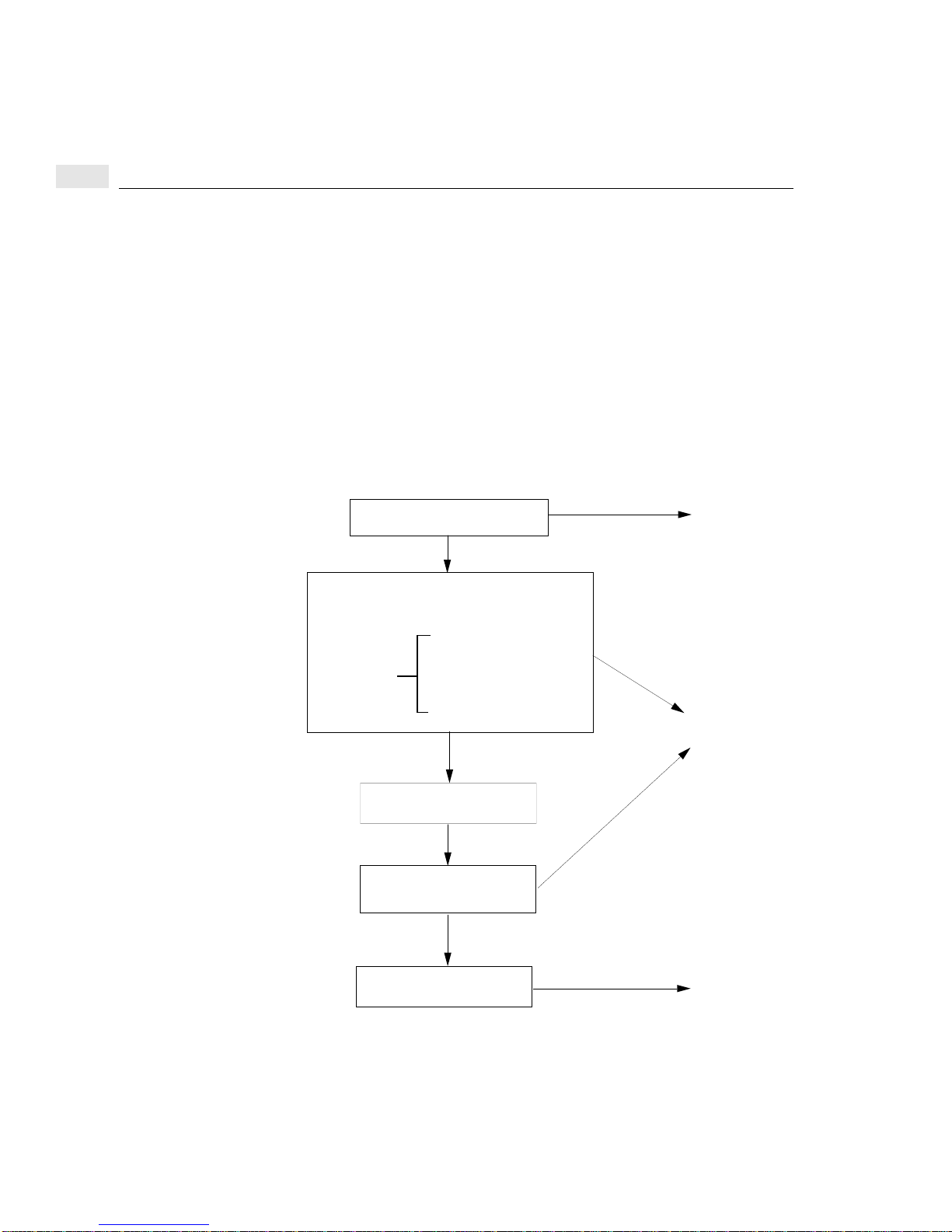
4
When the DTC is switched on, it is configured with:
• information that the DTC sends to the manager (such as the number of
boards)
• user-defined settings
• and other parameters such as the DTC IP address that you enter when you add
a new DTC to the configuration.
In most cases you can successfully configure your DTCs with information contained
in chapter 5. This will enable you to connect terminals to your DTCs. If your site
requires a more complex configuration refer to the appropriate chapter later in this
book.
The configuration procedure
Run the dtcconfig program
Add DTC Configuration
Choose DTC name
DTC LAN address
Find
Power the DTC off/on
Connect terminal and
DTC IP address
DTC nodename
DTC type
get DTC prompt
This Chapter
Chapter 5
40
Configure a DTC printer
Chapter 8
Page 41

To start the dtcconfig utility
To start the dtcconfig utility
Once you have installed the DTC Manager/UX you are ready to configure your
DTC.
Note The dtcconfig command requires superuser privileges.
Make sure you logon as root or type the HP-UX su (superuser) command.
At the shell prompt, enter:
dtcconfig
The complete dtcconfig command syntax is as follows:
dtcconfig [-a] [-l loglevel] [-L logfile]
Parameter Description
-a Appends the log messages from this dtcconfig execution to the existing dtcconfig
log file. By default, executing dtcconfig overwrites the log file. The default log file
is /var/opt/dtcmgr/log/dtcconfig.log.
4
-l
loglevel
-L
logfile
Sets the amount of information that will be logged in the log file for this dtcconfig
execution. Specify one of the following logging levels:
0 Logs only startup and termination messages of dtcconfig.
1 Logs serious and fatal error messages and level 0 messages.
This is the default logging level.
2 Logs warning and informational messages and level 1
messages.
Specifies an alternative log file that dtcconfig should use to log the messages. The
default file is /var/opt/dtcmgr/log/dtcconfig.log .
When you execute the dtcconfig command, the console screen will display the DTC
Configuration Main Menu.
41
Page 42

4
Using the dtcconfig menus
Using the dtcconfig menus
The DTC configuration tool (dtcconfig) provides menus, fields, and function keys to
help you configure your DTC devices. It has three types of menus:
• Main menu: used to access other menus and functions.
• Actions menu: provides you with a selection of possible actions you can take
from the current screen.
• Data acquisition menu: provides you with a list of possible field values. This
menu is displayed by pressing the Help (F1) function key.
You can select a menu item in one of two ways:
• Use the arrow keys or Tab to move from one item to the next. Once the desired
menu item is highlighted: press Return, or the Select Item or Select Action (F4)
function key to start the operation.
• Type the first character of the menu item (for example, a for Add DTC
Configuration). The DTC manager immediately executes the command
associated with that letter (you do not have to press Return). If several options
start with the same letter, enter the letters of the option until it is unique (for
example, con for the Configure option and cop for the Copy function). This
abbreviated method does not work when selecting from a list of valid field options
such as found in a HELP screen.
42
If you enter an incorrect value for a field, an error message window appears. Read
the message and press the space bar to return to the screen and to correct the entry.
The following keyboard keys are used to enter information at the various dtcconfig
screens:
• Tab and arrow keys. If the Tab key does not let you move to another field, try
using the arrow key.
• Space bar. When an error message is displayed, you must press the space bar to
continue.
• Function keys. Explained in the next section, function keys vary for different
screens.
• Return key, Perform Task (F4), and Done (F4) function keys. Read the popup window message or look at the bottom of the screen to know which of these
keys to press.
Page 43
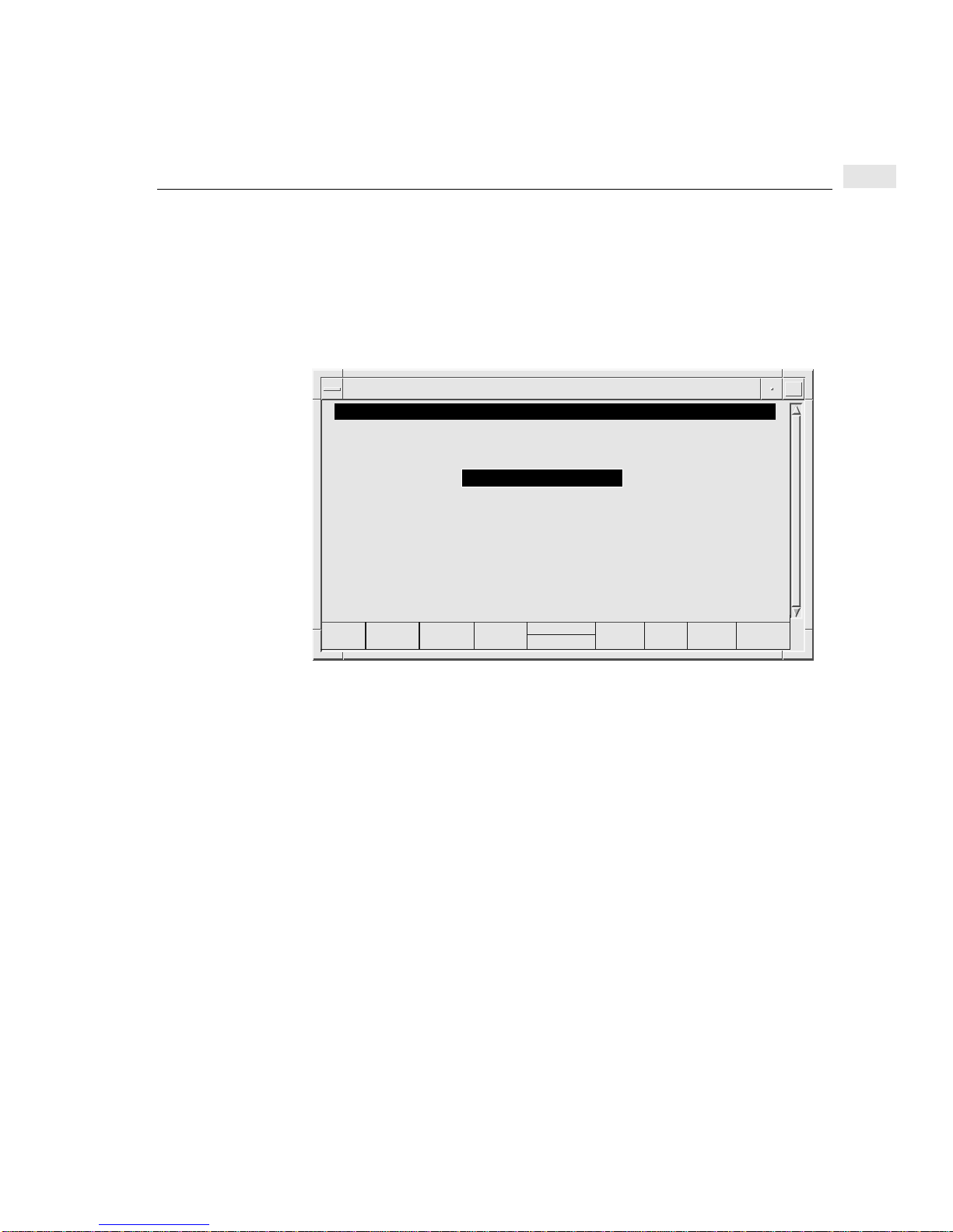
The main menu
The main menu
The DTC configuration main menu gives you several options for configuring your
DTC devices. Use the Tab or arrow key to choose a menu item. Press Return or the
Select Item (F4) function key to start the task.
DTC Configuration Main Menu
tsta195:root:/opt/dtcmgr/sbin
DTC Configuration Main Menu
Highlight an item and then press “Return” or “Select Item” (F4).
Add DTC Configuration ..
Modify DTC Configuration ....
Delete DTC Configuration ...
Modify Default Parameters ->
Help for Using DTCconfig
4
Help
Shell
Select
Item
Exit
DTCconf
tsta195:root
• Add DTC Configuration—enables you to add one or more non-configured
DTCs to your list of DTCs. Their configurations are initially the same. See
chapter 5 for more information on this menu item.
• Modify DTC Configuration—enables you to modify or reconfigure an existing
DTC configuration. You can also modify DTCs with the dtcmodifyconfs
command (which cannot be used when dtcconfig is running). See chapter 6 for
more information on this menu item.
• Delete DTC Configuration—enables you to delete one or more DTCs from your
list of DTCs. See chapter 9 for more information on this menu item.
• Modify Default Parameters—enables you to modify the user default CPU/LAN
or LAN configuration and the default port configuration. See chapter 9 for more
information on these tasks.
• Help for Using DTCconfig—Displays help information and an overview of the
DTC manager screens and navigation keys.
43
Page 44

4
Using the function keys
Using the function keys
Use the function keys (indicated at the bottom of the screen) to execute functions.
Note Note that the function keys are context sensitive and perform different operations
depending on the current screen.
The following keys have specific functions:
(F1)–Help: used to obtain a summary of information for a particular field or menu
item. For the modify and delete functions of dtcconfig, the Help function key
provides you with a list of DTCs to modify or delete. This function key is on almost
every screen.
(F3)–Shell: Used to temporarily access the HP-UX shell. After you have finished
entering shell commands, type exit to return to the dtcconfig utility. This function
key does not appear on every screen. You cannot execute another dtcconfig,
dtcdiag, dtcping or dtcmodifyconfs command from the shell because only one
instance of these commands can run at a time.
(F4)–Multi function Key
44
(F5)–Actions Menu: Used to access the Actions Menu.
(F6)–Default Values: Used to choose a set of default values for a set of fields.
(F8)–Exit: Used to leave the current screen. Refer to see “Exiting from dtcconfig”
on page 46 for more information. This function key is always available.
Page 45

Using the editing keys
You use the dtcconfig editing keys to enter values in the various fields.
You should note that some of the editing keys do not function as they normally
would if you were editing text. Specifically, the following keys behave differently:
• [Clear Line]—If you use this key while entering a value in a field, you do not get
a response. The line is not cleared and you must return to the beginning of the
field to start entering the value again.
• [Delete Line]—This key deletes all the data on the line. However, in order to
enter a new value on that line, you must move the cursor to the beginning of the
line.
• [Insert Char]—It is best to make sure that Insert Character mode is off. In some
fields, Insert Character mode is functional. However, in most fields, using it
results in no action from the keyboard (that is, the keyboard does not respond
when you try to type a value into a field).
• [Clear Display]— This key is disabled.
• [Insert Line]— This key is disabled.
Using the editing keys
4
• [Enter]—This key should not be used and has unpredictable results. Use the
Return key.
Refreshing the screen
Sometimes the screen may become difficult to read due to line or data rate problems.
If this happens, type [Ctrl]-L and the screen will be redisplayed in its correct form.
If this continues to happen, check the line rate and terminal configuration and ensure
that it matches the DTC port configuration.
45
Page 46

4
Getting help
Getting help
There are three areas of online help:
• The Help for Using DTCconfig menu item from the main menu. Selecting this
menu item displays general dtcconfig help information. This is an overview of
the dtcconfig screens and the keyboard keys.
• Help (F1) function key. Almost all dtcconfig screens include a Help function
key. Pressing this function key provides information about the field you are
currently in.
• List of DTCs. From the Delete DTC Configuration or Modify DTC
Configuration screens, the Help (F1) function key displays a list of DTCs for
you to choose.
Exiting from dtcconfig
After pressing the Exit Task (F8) function key several times, you eventually return
to the dtcconfig main menu. From the main menu, when you press the Exit
DTCconf (F8) function key, a pop-up message prompts you to quit or not quit.
Enter a y to quit. Enter an n to remain in dtcconfig.
Note If you made modifications related to IP addresses, (for example, if you create a new
DTC or modify the configuration of the LAN address for an existing DTC),
dtccheckip will be launched automatically. You will only get output if there are
duplicated IP addresses.
46
Page 47

Adding DTCs
This chapter describes how to add one or more DTCs to the set of DTCs managed
by DTC Manager/UX.
Note 150 is the maximum number of manageable DTCs.
Note The instructions in this chapter presume that DTC Manager/UX is already properly
installed and that you are familiar with the basic use of the dtcconfig menus and
function keys as described in chapter 4.
Procedure overview
5
When a DTC is added, a basic configuration is created on the management system.
This initial configuration is created according to the user-defined DTC default
parameters.
DTC parameters are initially set to HP factory-defined default values. If you need to
modify these values you can use the dtcconfig utility’s Modify DTC Configuration
option to do so.
Refer to chapter 9 if you want to set your own default parameters.
Before the DTC begins a download process, it communicates its hardware
configuration to the management platform. The DTC Manager/UX uses this
information to automatically update its system image of the DTC. Physical settings
in the DTC configuration, such as added or deleted boards, as well as whether a port
group is modem or direct are reported to the DTC Manager/UX. All hardware
changes are automatically made to your DTCs.
47
Page 48
5
Adding a DTC to the configuration
Adding a DTC to the configuration
tsta195:root:/opt/dtcmgr/sbin
DTC Configuration Main Menu
Highlight an item and then press “Return” or “Select Item” (F4).
Add DTC Configuration ..
Modify DTC Configuration ....
Delete DTC Configuration ...
Modify Default Parameters ->
Help for Using DTCconfig
Help
Shell
Select
Item
tsta195:root
Exit
DTCconf
Click here, or press F1 for online help
DTC Name
Add DTC Configuration
To create a default configuration for new DTCs (where all ports are configured as
terminal ports):
1 Ensure that the DTCs are properly connected to the LAN and then switch them
off and then on again.
2 Start the dtcconfig program by typing;
dtcconfig
3 Choose the Add DTC Configuration option from the main menu.
The Add DTC Configuration screen appears (see “Configuration parameter
definitions” on page 50 for an explanation of these fields).
4 Create a DTC list containing DTCs of one of the four types (DTC 16TN,
DTC 16, DTC 72MX or DTC 48). To configure a DTC 16MX, proceed as if you
were adding a DTC 16TN. When managed by the DTC Manager/UX, the
DTC 16MX is configured and functions exactly like a DTC 16TN.
• Press Return or TAB, or use the arrow keys to move to each field.
• Use the online help for more information about each field.
• Enter the number of DTCs you want in a list.
48
Page 49
The fields of the previous DTCs scroll upward allowing you to enter more
DTCs. All of the DTCs must be of the same DTC type (DTC 16TN,
DTC 16, DTC 48 or DTC 72MX) and will be set to the same configuration.
Add DTC Configuration screen
tsta195:root:/opt/dtcmgr/sbin
Add DTC Configuration
Fill in the fields and then press “Perform Task” (F4)
DTC Name DTC LAN Address DTC IP Address DTC Node Name
mydtc1
mydtc2
______
______
______
______
______
______
DTC Type (mark one with an “x”):
x DTC 16TN _ DTC 16 _ DTC 48 _ DTC 72MX
08-00-09-0007-40
08-00-09-01-32-12
_______________
_______________
_______________
_______________
_______________
_______________
Adding a DTC to the configuration
15.128.131.90__
15.128.131.72__
______________
______________
______________
______________
______________
______________
mydtc1.mysys.mycorp
mydtc2.mysys.mycorp
__________________
______
__________________
______
__________________
______
__________________
______
__________________
______
__________________
5
Help
Shell
Perform
Task
tsta195:root
Exit
Task
5 When you have completed your list of DTCs, press the Perform Task (F4)
function key. The DTCs in the list are automatically configured and added to the
management database and the Add DTC Configuration screen is cleared.
6 Create another DTC list for another type of DTC on your network.
7 When you have entered all your DTCs, exit from the Add DTC Configuration
screen by pressing the Exit Task (F8) function key.
You are returned to the main menu.
8 Exit from dtcconfig.
9 Turn each DTC’s power off and then on (power off/on).
Wait a few minutes for the configuration to be downloaded to the DTC. The
DTC is now operational.
49
Page 50

5
Checking the terminal connections
Checking the terminal connections
Follow these steps for each terminal connected to the DTC.
1 Press Return. The DTC prompt, usually DTC>, should appear. Enter the
connect command with the IP address1 of the system you want to connect to.
DTC> connect 15.13.12.12
Connection #1 established to mysystem.mygroup.mycorp
To return to DTC interface, type <CTRL>K
login:
2 If you are not successful, try to modify the configuration of the DTC (refer to
chapter 6). If the DTC does not respond, it probably means that the DTC LAN
address is not correct. Delete the DTC and then add it again.
3 If you still cannot establish a connection, go to the troubleshooting section in
chapter 15.
Configuration parameter definitions
DTC Name Enter a name consisting of up to 8 alphanumeric characters. You can include
hyphens (-) and underscores (_) but the first character must be alphabetic. The DTC
name field must not be left blank.
50
The DTC name is a unique name used by the DTC manager to identify a particular
DTC. For simplicity, the DTC name and the nodename portion of the DTC node
name are often the same name. However, they are used for separate tasks by the
DTC Manager/UX and the system.
1 You can only use a system name here if you have configured the system name in the DNS server.
Page 51

Configuration parameter definitions
DTC LAN Address Look for the DTC LAN address on your DTC and enter this value. Ensure that you
enter this address exactly as it is marked on the DTC. If you enter an incorrect DTC
LAN address, the DTC will not operate.
Hewlett-Packard has assigned each DTC a unique DTC LAN address which is
indicated on an address label as follows:
DTC 16TN—on the back panel near the port connections
DTC 16—on the back panel in the upper right corner
DTC 48—inside the front panel
DTC 72MX—on the back panel on the LAN board
When a DTC is first added, the DTC LAN address field in the Add DTC
Configuration screen indicates 00-00-00. Replace this with your DTC LAN
address. The format of the LAN address is usually 08-00-09-xx-xx-xx
or 00-60-B0-xx-xx-xx where xx is a hexadecimal number.
Note When configuring a DTC for connection to your HP 9000 system, the IEEE 802.3
protocol is used on the LAN connection. However, for communication between the
terminal and the system, the Ethernet protocol is used. Ethernet and IEEE 802.3 LAN
protocols are similar, and can coexist on the same physical LAN, using the same
physical address configured in the DTC LAN Address field. The address you define
here will also be used as the Ethernet address for the DTC.
5
DTC IP Address Enter a value in the form xxx.xxx.xxx.xxx where xxx is a decimal number from 0
through 255. The address cannot be 0.0.0.0 or 255.255.255.255 which are reserved
addresses. Assign a unique IP address to each DTC.
If you use a DNS server, you must first add each DTCs IP address and, secondly,
configure the DTC for DNS.
Note In the “Add DTC Configuration” screen, you must enter a value for DTC IP address
even if you do not use the DNS server.
Each DTCs IP address must also be added to your name database, for example the
/etc/hosts file or the DNS (Domain Name System) server. The/etc/hosts file
is documented in the manual, Installing and Administering LAN/9000 Software.
This parameter is the IP address of the DTC itself. Do not confuse it with the IP
address of the host system, or with the IP address of a port.
51
Page 52

5
Configuration parameter definitions
DTC Node Name Enter a name in three parts, each with a maximum of 16 characters, separated by
periods as illustrated in the example syntax below.
nodename.domain.organization
Each part must start with an alphabetic character and can be followed by a
combination of alphanumeric characters, hyphens (-), and underscores (_). As you
enter the name, it shifts right to extend beyond the visual line.
The DTC Node Name is a unique node name to identify a DTC within a system or
network.
For simplicity, the DTC name and thenodename portion of the DTC node name are
often the same name. However, they are used for separate tasks by the
DTC Manager/UX and the system.
DTC Type Enter an X or an x in one of these four fields: DTC 16TN (also use this field for a
DTC 16MX), DTC 16, DTC 48, or DTC 72MX. All the DTCs in a list must be of
the same type.
52
Page 53

Modifying DTCs with dtcconfig
This chapter describes how to modify a single DTC with the interactive dtcconfig
utility. The utility’s Modify DTC Configuration menu allows you to modify a
CPU/LAN (or LAN board), board, and/or port of a single DTC.
You can only modify one DTC at a time with dtcconfig. If you want to modify
multiple DTC configurations at the same time, use the dtcmodifyconfs command
(as described in chapter 10).
Note The instructions in this chapter presume that DTC Manager/UX is already properly
installed and that the DTC you want to modify is physically present on the network
and switched on. In addition, it is presumed that you are familiar with the basic use
of the dtcconfig menus and function keys as described in chapter 4.
6
Once you have modified the DTC, refer to the appropriate chapter to:
• modify CPU/LAN board or LAN board parameters for a single DTC (chapter 7)
• modify terminal, printer port and other parameters on a board of a single DTC
(chapter 8)
• copy DTC board and port configurations (chapter 9).
53
Page 54

6
Modifying a DTC configuration
Modifying a DTC configuration
1 Run dtcconfig to access the DTC Configuration Main Menu.
2 Select Modify DTC Configuration from the main menu.
3 A pop-up window asks you for the name of the DTC whose configuration you
want to modify.
• Type in a DTC name
or
• Press the Help (F1) function key to see the list of existing DTCs. Highlight
the DTC on the list you want to modify and press Return or the Select Item
(F4) function key.
4 The DTC Rear Panel Configuration screen appears. Enter the board and port
numbers to be modified.
Refer to the online help for detailed explanations of the board and port fields.
5 Press the Action Menu (F5) function key and select the option you want. The
Action Menu varies depending upon the type of DTC or board.
6 When you have finished modifying parameters, press the Action Menu (F5)
function key.
54
You can then either specify another board and port or exit.
7 To exit, press the Exit Task (F8) function key. You then leave the Rear Panel
Configuration screen and return to the main menu of dtcconfig.
Page 55
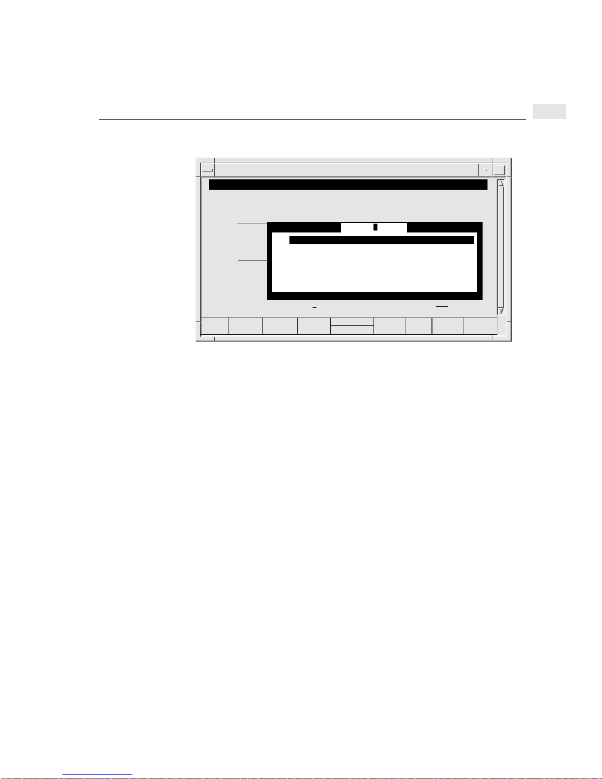
Modify DTC Configuration screen
tsta195:root:/opt/dtcmgr/sbin
Rear Panel Configuration
Fill in the DTC 16TN board and port fields and then press “Action Menu” (F5).
|
0
|
|
8
-------------
|
|
Board (L = LAN, or B - board): L Port (0 - 15):
Help
Configure LAN Addresses ...
Configure Global Parameters ...
Configure TCP Parameters ...
Configure DNS/IP Parameters ...
Configure SNMP Authorization Filters ...
Configure SNMP/MIB Data Parameters ...
Configure DTC Management Protocol Parameters ...
Select
Action
juin
Action Menu
tsta195:root
If you changed any of the following:
Modifying a DTC configuration
Exit
Window
6
• DTC node name
• DTC IP address
• TCP timers
• any of the following SNMP parameters:
• contact name
• sys name
• sys location
• SNMP enable authentication traps
• trap destination IP address
• or DTC management protocol parameters
you must download the new configuration to the DTC.
55
Page 56

6
Using the Rear Panel Configuration screen
There are two ways to reset the DTC and start the download:
• turn the DTC off and then on
or
• run the command dtcreset dtcname.
Note You must reset the DTC after modifications to save your changes. Do not use the
Modify DTC Configuration option on this DTC again until you have reset the DTC.
Otherwise you may lose the changes you have just made.
Using the Rear Panel Configuration screen
The Rear Panel Configuration screen represents the rear of the DTC and is the
starting point for all DTC configuration procedures.
The Rear Panel Configuration screen allows you to perform the following tasks:
• Configure global DTC parameters on the CPU/LAN or LAN board
56
• Configure ports on a particular board (see “Configuring terminal and printer
ports” on page 87).
• Copy a board within a DTC or to another DTC (see “Copying and pasting a board
or port” on page 120).
• The Rear Panel Configuration screen for each type of DTC is shown on the
following pages.
1 Select Modify DTC Configuration from the main menu of the dtcconfig utility.
2 A pop-up window asks you for the name of the DTC whose configuration you
want to modify.
• Type in a DTC name
or
• Press the Help (F1) function key to see the list of existing DTCs. Highlight
the DTC on the list you want to modify and press Return or the Select Item
(F4) function key.
The DTC Rear Panel Configuration screen appears.
Page 57

Entering values in the board and port fields
This section explains what you should enter in the Board and Port fields of the
Rear Panel Configuration screen.
Configuring Global Parameters (not specific to a given port)
1 Enter the appropriate value in the board field as follows:
DTC 16TN: L or l, for the LAN board. The LAN board is factory
installed on a DTC 16TN.
DTC 16: C or c, for the CPULAN board.
DTC 48: C or c, for the CPU/LAN board.
DTC 72MX: The number corresponding to the LAN board. The LAN
board can be in any slot but is usually in slot 0. You can
specify the LAN board using L, l, or the number of the
board.
2 Press the Action Menu (F5) key.
3 Choose the menu item corresponding to the DTC parameter you want to change.
Using the Rear Panel Configuration screen
6
Use the following information to configure the DTC global parameters.
Configuring port parameters
Note You cannot go to the port field of the Rear Panel Configuration screen if you specify
C, c, L or l in the board field.
1 Specify the number of the board where the port you want to configure is located.
Valid values are:
DTC 16TN: B or b specifies the 16 ports of a DTC 16TN. A DTC 16TN has
no separate boards, but is often referred to as having one board of
16 ports and a LAN board.
DTC 16: 0 or 1.
DTC 48: 0 through 5.
DTC 72MX: 0 through 3.
57
Page 58

6
Using the Rear Panel Configuration screen
2 Use the arrow key, not the TAB key, to go to the Port field. Enter a port number
depending upon the DTC type. The following port values are valid:
DTC 16TN: 0 through 15 direct connect or modem ports
DTC 16: 0 through 7 direct connect ports
0 through 5 modem ports
DTC 48: 0 through 7 direct connect ports
0 through 5 modem ports
DTC 72MX: 0 through 23 direct connect or modem ports
3 Press the Action Menu (F5).
4 Choose the menu item corresponding to the DTC parameter you want to change.
Refer to chapter 8, to configure ports.
58
Page 59
Rear panel configuration screen examples
Rear panel configuration screen examples
Rear Panel Configuration screen for a newly-added DTC 16TN
tsta195:root:/opt/dtcmgr/sbin
Rear Panel Configuration
juin
Fill in the DTC 16TN board and port fields and then press “Action Menu” (F5).
6
|
0 T
1 P
2 T
|
8 T
9 T
|
-------------------------------------------------------------------
|
|
Board (L = LAN, or B = board): Port (0 - 15):
Help
Shell
3 P 4 T 5 T 6 T 7 T
10 T
11 T 12 T 13 T 14 T 15 T
LAN
tsta195:root
Action
Menu
|
DIRECT
|
DIRECT
----------------|
|
Rear Panel Configuration screen for a newly-added DTC 16
tsta195:root:/opt/dtcmgr/sbin
Rear Panel Configuration
Fill in the DTC 16 board and port fields and then press “Action Menu” (F5).
Board 0 Board 1 Board 2
0 T
2 T
4 T
1 T
3 T
5 T
NESS
(Unused)
CPU/LAN
|
|
|
|
|
Exit
Task
Board (C = CPU/LAN, or 0 - 1 = board): Port (0 - 7):
Help
Shell
edith74:/use
Action
Menu
Exit
Task
59
Page 60
6
Rear panel configuration screen examples
Rear Panel Configuration screen for a newly-added DTC 48
tsta195:root:/opt/dtcmgr/sbin
Rear Panel Configuration
cassis
Fill in the DTC 48 board and port fields and then press “Action Menu” (F5).
Board 5
Board 4
Board 3
Board 2
Board 1
Board 0
0 T 2 T 4 T1 T 3 T 5 T
CPU/LAN
Board (C = CPU/LAN, or 0 - 5 = board): Port (0 - 7):
Help
Shell
tsta195:root
Action
Menu
Rear Panel Configuration screen for a newly added DTC 72MX
tsta195:root:/opt/dtcmgr/sbin
Rear Panel Configuration
Fill in the DTC 72MX board and port fields and then press “Action Menu” (F5).
0 T 2 T 4 T1 T 3 T 5 T
8 T 9 T 10 T
16 T 17 T 18 T 19 T 20 T 21 T 22 T 23 T
0 T 2 T 4 T1 T 3 T 5 T
8 T 9 T 10 T
16 T 17 T 18 T 19 T 20 T 21 T 22 T 23 T
Board (L = LAN, or 0 - 3 = board): Port (0 - 23):
Help
11 T 12 T 13 T 14 T 15 T
11 T 12 T 13 T 14 T 15 T
Shell
LAN
wally
6 T 7 T DIRECT
6 T 7 T
tsta195:root
Action
Menu
DIRECT
DIRECT
DIRECT
DIRECT
DIRECT
Board 3
Board 2
Board 1
Board 0
Exit
Task
Exit
Task
60
Page 61

Configuring a DTC CPU/LAN or LAN board with
dtcconfig
This chapter describes how to use the dtcconfig utility to configure the CPU/LAN
or LAN board of a DTC (the global DTC parameters). These procedures are based
on the Modify DTC Configuration menu that provides functions to modify a single
DTC.
Note The procedures in this chapter presume that you have added at least one DTC to the
list of configured DTCs. It is also presumed that you are familiar with the basic use
of the dtcconfig menus and function keys as described in chapter 4.
If you want to modify multiple DTC configurations at the same time, use the
dtcmodifyconfs command (as described in chapter 10).
7
61
Page 62

7
Configuring CPU/LAN or LAN board parameters
Configuring CPU/LAN or LAN board parameters
You must configure the CPU/LAN or LAN Board in order to change the global
configuration of a single DTC.
When configuring the CPU/LAN or LAN Board, you can change the following
parameters for the specified DTCs:
• LAN addresses which include:
• DTC IP address
• DTC node name
• Global parameters which include:
• event logging classes
• DTC user interface timeout
• DTC user prompt
• DTC user welcome message
• Enable DTCDF access
• DTCDF password
• TCP parameters which are TCP timers that may need to be altered for extended
LAN configurations
• DNS/IP parameters which include:
• default DNS (domain name server) and backups
• default IP router addresses and backups
• SNMP authorization filters which include:
• your network's SNMP management nodes, the information that these nodes
can request and the rights of access to the SNMP MIB data
• SNMP/MIB data parameters which include:
• the SNMP-specific data to be stored on the DTC
• DTC management protocol parameters which include:
• the DTC management protocol parameters that may need to be altered for
traffic over LANs with bridges
62
Page 63
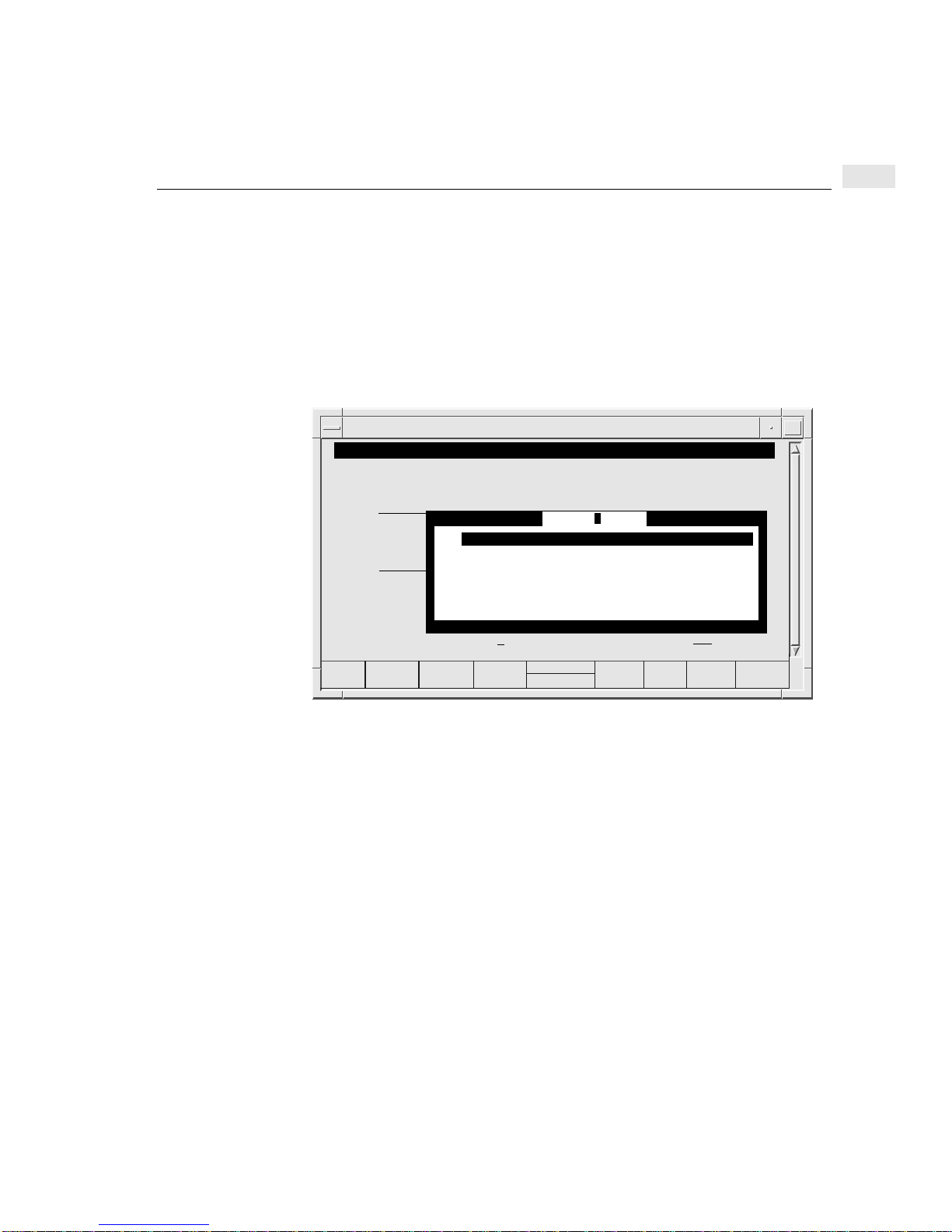
Configuring CPU/LAN or LAN board parameters
The basic steps for configuring the CPU/LAN or LAN board from the Rear Panel
Configuration screen are explained below.
1 Specify the CPU/LAN or LAN Board in the board field of the Rear Panel
Configuration screen.
2 Press the Action Menu (F5) function key for a list of action options (see the
screen below for an example).
Action Menu for CPU/LAN or LAN board of a DTC
tsta195:root:/opt/dtcmgr/sbin
Rear Panel Configuration
Fill in the DTC 16TN board and port fields and then press “Action Menu” (F5).
|
0
|
|
8
-------------
|
|
Configure LAN Addresses ...
Configure Global Parameters ...
Configure TCP Parameters ...
Configure DNS/IP Parameters ...
Configure SNMP Authorization Filters ...
Configure SNMP/MIB Data Parameters ...
Configure DTC Management Protocol Parameters ...
juin
Action Menu
7
Board (L = LAN, or B - board): L Port (0 - 15):
tsta195:root
Help
Select
Action
Exit
Window
3 Press the Select Action (F4) function key to choose one of the menu items which
are explained in the following sections.
4 A screen appears displaying the current values. Change the values you want to
change and press Done (F4). In some screens, you can choose HP defaults, userdefined defaults or enter other values. Press theDefault Values (F6) function key
to see the HP defaults and user-defined defaults.
63
Page 64
7
Configuring CPU/LAN or LAN board parameters
Modified CPU/LAN board
Fill in the DTC 72MX board and port fields and then press “Action Menu” (F5).
0 T 2 T 4 T1 T 3 T 5 T
8 T 9 T 10 T
16 T 17 T 18 T 19 T 20 T 21 T 22 T 23 T
0 T 2 T 4 T1 T 3 T 5 T
8 T 9 T 10 T
16 T 17 T 18 T 19 T 20 T 21 T 22 T 23 T
Board (L = LAN, or 0 - 3 = board): Port (0 - 23):
tsta195:root:/opt/dtcmgr/sbin
Rear Panel Configuration
11 T 12 T 13 T 14 T 15 T
11 T 12 T 13 T 14 T 15 T
wally
6 T 7 T DIRECT
6 T 7 T
LAN
DIRECT
DIRECT
DIRECT
DIRECT
DIRECT
Board 3
Board 2
Board 1
Board 0
Help
Shell
tsta195:root
Action
Menu
Exit
Task
5 After entering values, press the Done (F4) function key. The Rear Panel
Configuration screen appears again.
6 Press the Action Menu (F5) if you want to choose another menu item.
7 To exit, press the Exit Task (F8) function key. You then leave the Rear Panel
Configuration screen and return to the main menu of dtcconfig.
64
Page 65
Configuring LAN addresses
Highlight an item and then press “Return” or “Select Item” (F4).
Help
Shell
tsta195:root:/opt/dtcmgr/sbin
DTC Configuration Main Menu
Add DTC Configuration ..
Modify DTC Configuration ....
Delete DTC Configuration ...
Modify Default Parameters ->
Help for Using DTCconfig
tsta195:root
Select
Item
Rear Panel Configuration
Board = C or L
Action Menu (F5)
Configure LAN Addresses
Configuring LAN addresses
Exit
DTCconf
DTC NameClick here, or press F1 for online help
7
1 Select Configure LAN Addresses from the Action Menu as shown above. The
LAN Address Configuration screen appears.
2 Enter the appropriate address information in the provided fields (see the
following pages for parameter definitions).
3 When you have finished entering values, press the Done (F4) function key. You
are returned to the Rear Panel Configuration screen.
4 The parameters in this screen cannot be modified dynamically. Exit from
dtcconfig and download the changes to the DTC by executing the following
command at the shell prompt:
dtcreset
dtcname
65
Page 66
7
Configuring LAN addresses
LAN Address Configuration screen
edith74:/users/edith
LAN Address Configuration
Rear Panel Configuration
Fill in the DTC 16TN board and port fields and then press “Action Menu” (F5).
DTC LAN Address . . . . . . . 08-00-09-28-0A-66 (not modifiable)
DTC IP Address . . . . . . . . .
DTC Node Name . . . . . . . . MICHIGAN.GND.HP
Fill in or modify the desired fields and then press “Done” (F4).
|
0
|
|
8
-------------
|
|
MICHIGAN LAN board
015.128.240.061
Configure LAN Addresses ...
Configure Global Parameters ...
Configure TCP Parameters ...
Configure DNS/IP Parameters ...
Configure SNMP Authorization Filters ...
Configure SNMP/MIB Data Parameters ...
Configure DTC Management Protocol Parameters ...
Board (L = LAN, or B - board):
Help
L Port (0 - 15):
edith74:/use
Done
Exit
Window
LAN address parameter definitions
DTC IP Address
Enter a value in the form xxx.xxx.xxx.xxx where xxx is a decimal number from 0
through 255. The address cannot be 0.0.0.0 or 255.255.255.255 which are reserved
addresses. Assign a unique IP address to each DTC. (For more information on the
DTC IP address, see Chapter 5).
DTC Node Name Enter a name consisting of three parts, each with a maximum of 16 characters,
separated by periods (.) and in the following form:
nodename.domain.organization
For simplicity, the DTC name and thenodename portion of the DTC node name are
often the same name. For example, the dtcname could be mydtc1 and the DTC
node name could be mydtc1.mysys.mycorp.
66
Page 67
Configuring global parameters
tsta195:root:/opt/dtcmgr/sbin
DTC Configuration Main Menu
Highlight an item and then press “Return” or “Select Item” (F4).
Add DTC Configuration ..
Modify DTC Configuration ....
Delete DTC Configuration ...
Modify Default Parameters ->
Help for Using DTCconfig
Help
Shell
Select
Item
tsta195:root
Configuring global parameters
DTC NameClick here, or press F1 for online help
Rear Panel Configuration
Board = C or L
Action Menu (F5)
Global Parameters Configuration
7
Exit
DTCconf
The parameters in the Global Parameters Configuration screen enable you to
specify the DTC user interface timeout, the DTC user prompt, and the DTC
welcome message. These parameters are used by the DTC terminal user interface
(described in appendix A).
Enter the appropriate values in the provided fields and then press the F4 key.
67
Page 68
7
Configuring global parameters
Global Parameters Configuration screen
tsta195:root:/opt/dtcmgr/sbin
Global Parameters Configuration
Fill in or modify the desired fields and then press “Perform Task” (F4).
Event Logging Class (mark with an “x” as many as desired):
1
-
DTC User Interface Timeout ( 5 - 300 seconds)
User Prompt (maximum of 16 characters)
Welcome Message (maximum of 400 characters - optional):
2
-
juin
3
-
-
. . . . . . . .
4
300
. .
DTC>
5
-
6
-
(optional)
Enable DTCDF Access
Help
Select
Action
tsta195:root
DTCDF Password AVESTA
Exit
Window
68
Page 69

Global parameter definitions
Configuring global parameters
7
Event Logging Class
Note Only use log events of class 2 (and higher) for:
Note Currently, Logging Class 4 does not supply event information even if the field is
Move the cursor to the logging class fields whose corresponding events you want to
log. The dtclist command is used to display the event logs (see Appendix B).
- troubleshooting
- one DTC at a time
The logging classes for events are as follows:
• Class 1—Catastrophic (default logging class)
• Class 2—Critical
• Class 3—Non-critical
• Class 4—Not Used
• Class 5—Informative
• Class 6—Statistical
Logging Class 1 is always selected and operational. Additional levels can also be
logged by entering an x in the corresponding field.
marked.
DTC User Interface
Timeout
Specify a timeout value between 5 and 300 seconds for the DTC. The default
timeout is 300 seconds. A terminal user using the connect command to connect to a
system via the DTC must attempt to connect to the system within this amount of
time.
The DTC waits this amount of time before the DTC Terminal User interface is
disconnected. Once the terminal has established a connection with a system via the
DTC, the timeout is disabled until the user returns to the DTC user interface.
The DTC User Interface Timeout can be enabled and disabled from the Enable
Port Options screen (see “Enabling port options” on page 99). By default, the DTC
User Interface Timeout is disabled.
69
Page 70

7
Configuring global parameters
User Prompt If you want a user prompt that is different from the default prompt, DTC>, specify a
prompt of up to 16 alphanumeric characters. Non-displayable ASCII characters
must be specified in caret-character format (for example, ^K means Ctrl-K). Use a
backslash before a literal caret (^) and a backslash (\).
The User Prompt is the DTC prompt seen by a user at a terminal connected to a
DTC. You may want to change the user prompt to the name of your DTC (for
example, MYDTC1>) to help you keep track of your DTCs. Only users connected
to ports with the switching capability see the prompt. Other users connected directly
to a host system do not see the DTC user prompt.
Switching is the ability to connect to more than one computer from a terminal.
Switching is automatically enabled for all terminal ports.
Welcome Message If you want to provide a welcome message, enter up to 390 alphanumeric characters.
Non-displayable ASCII characters must be specified in caret-character format (for
example, ^K means Ctrl-K). Put a backslash (\) before a literal caret (^) or a
backslash (\) to ensure these characters appear correctly on the screen. The welcome
message is an optional parameter.
Do not use the keyboard Enter key (carriage return) to create line breaks in the
welcome message. Using the Enter key terminates the DTC configuration steps.
Use the ^M^J (Ctrl-M, Ctrl-J) keys to force the text onto the next line.
Enable DTCDF
Access
70
The welcome message is the message displayed on a terminal connected to a DTC
when
• a terminal user opens a connection to a port configured for system switching
• a terminal user connected to the DTC user interface issues the “status command”
Only users connected to ports with switching capability see the welcome message.
The welcome message is not displayed when a user switches back from a system
connection to the DTC user interface.
This field enables a Hewlett-Packard support engineer to access DTC memory for
troubleshooting. Access is protected by a password. Put an X or an x in this field to
enable a Hewlett-Packard support engineer access your DTC and to format DTC
memory dumps.
The default setting is so that Hewlett-Packard cannot access your DTC.
Page 71

Configuring global parameters
DTCDF Password This field contains the password you must give to your Hewlett-Packard support
engineer to allow access to DTC memory for troubleshooting.
Enter up to eight alphanumeric characters as the DTCDF password. The initial
setting is AVESTA.
7
71
Page 72
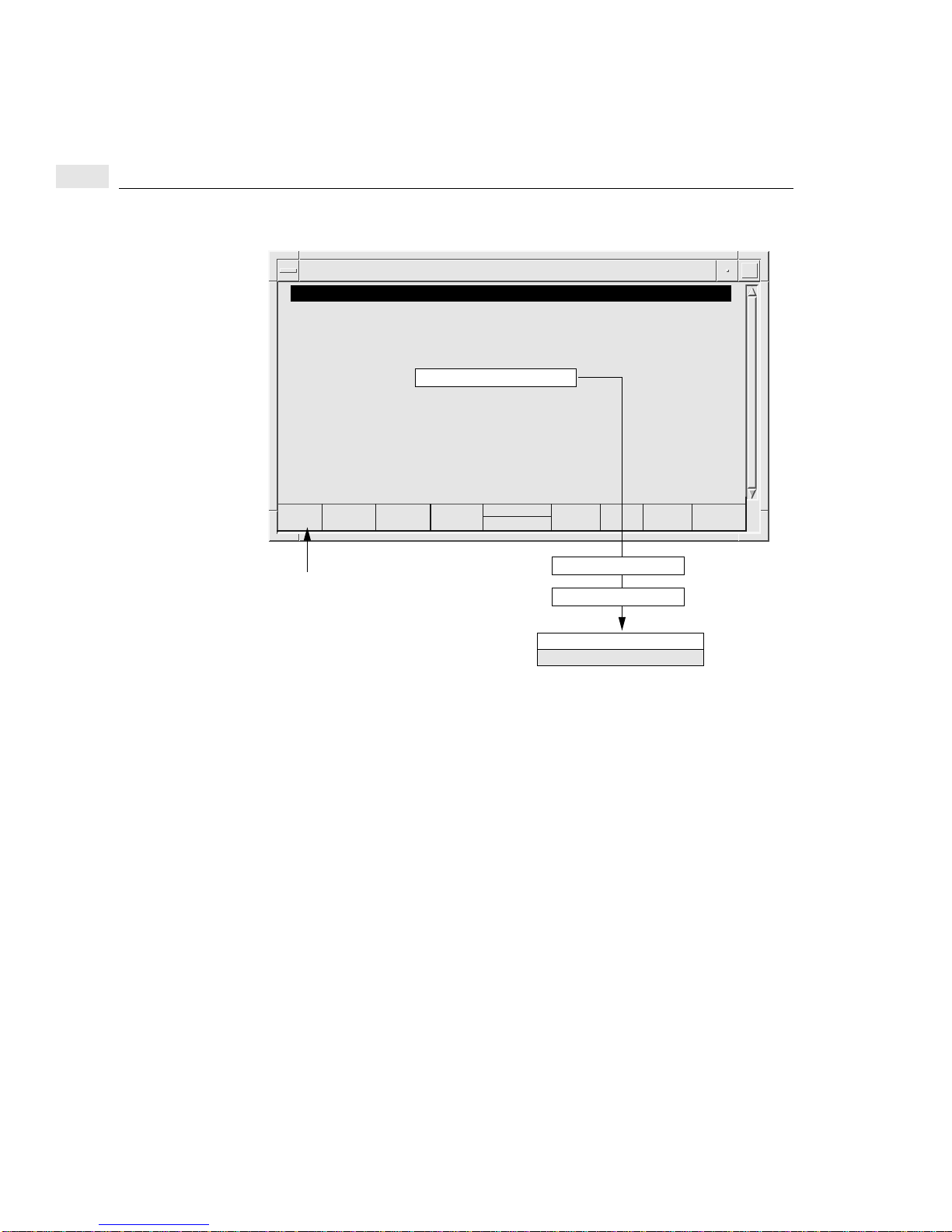
7
Configuring TCP parameters
Configuring TCP parameters
Highlight an item and then press “Return” or “Select Item” (F4).
Help
Shell
tsta195:root:/opt/dtcmgr/sbin
DTC Configuration Main Menu
Add DTC Configuration ..
Modify DTC Configuration ....
Delete DTC Configuration ...
Modify Default Parameters ->
Help for Using DTCconfig
tsta195:root
Select
Item
Rear Panel Configuration
Board = C or L
Action Menu (F5)
Configure TCP Parameters
Exit
DTCconf
DTC NameClick here, or press F1 for online help
72
The Configure TCP Parameters screen is used to specify TCP timing information
for different LAN and extended LAN configurations.
1 Use the TAB key to move to a set field. Place an x or X to choose the set. The
timer values are defined by the set of values that you choose (see “The five sets
of TCP values” on page 73).
• Set 1—(the HP Default setting) for traffic over the LAN only.
• Set 2—for traffic over a LAN with bridges.
• Set 3—for traffic over a LAN with exceptionally high transmission times.
• Set 4—for networks with high data losses.
• Set 5—for extended switching applications over a LAN, or a LAN with
bridges.
2 Press the Done (F4) function key to return to the Rear Panel Configuration
screen.
Page 73
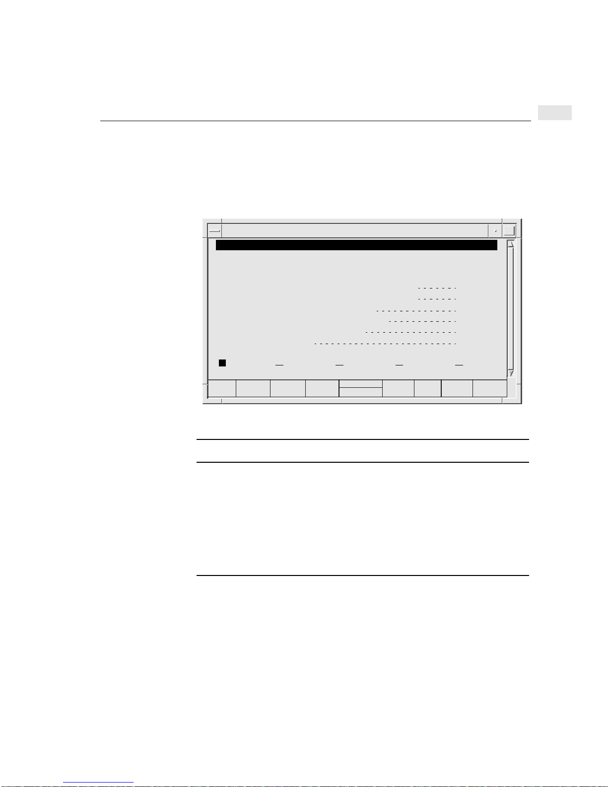
Configuring TCP parameters
3 The TCP parameters cannot be modified dynamically. Exit from dtcconfig and
download the changes to the DTC by executing the following command at the
shell prompt:
7
dtcreset
dtcname
TCP Parameters Configuration screen
tsta195:root:/opt/dtcmgr/sbin
TCP Parameters Configuration
wally LAN board
Mark with an “x” the set of TCP parameters to configure.
Then press “Return” or “Done” (F4).
Maximum Data Retransission Timer (in tenths of seconds)
Minimum Data Retransmission Timer (in tenths of seconds)
Stand-Alone ACK Timer (in tenths of seconds)
Connection Assurance Timer (in tenths of seconds)
Window Probe Timer (in tenths of seconds)
Number of Retries for Data
x
Help
Done
tsta195:root
Set 4Set 3Set 2Set 1
Default
Values
20
1
4
3000
1200
4
Set 5
Exit
Window
The five sets of TCP values
TCP Parameter Set 1 Set 2 Set 3 Set 4 Set 5
Maximum data retransmission timer 20 100 200 200 50
Minimum data retransmission timer 1 3 5 5 1
Stand-alone acknowledgement timer 4 4 4 0 0
Connection assurance timer 3000 3000 3000 3000 3000
Window probe timer 1200 1200 1200 600 1200
Number of retries for data 4 6 6 10 6
73
Page 74
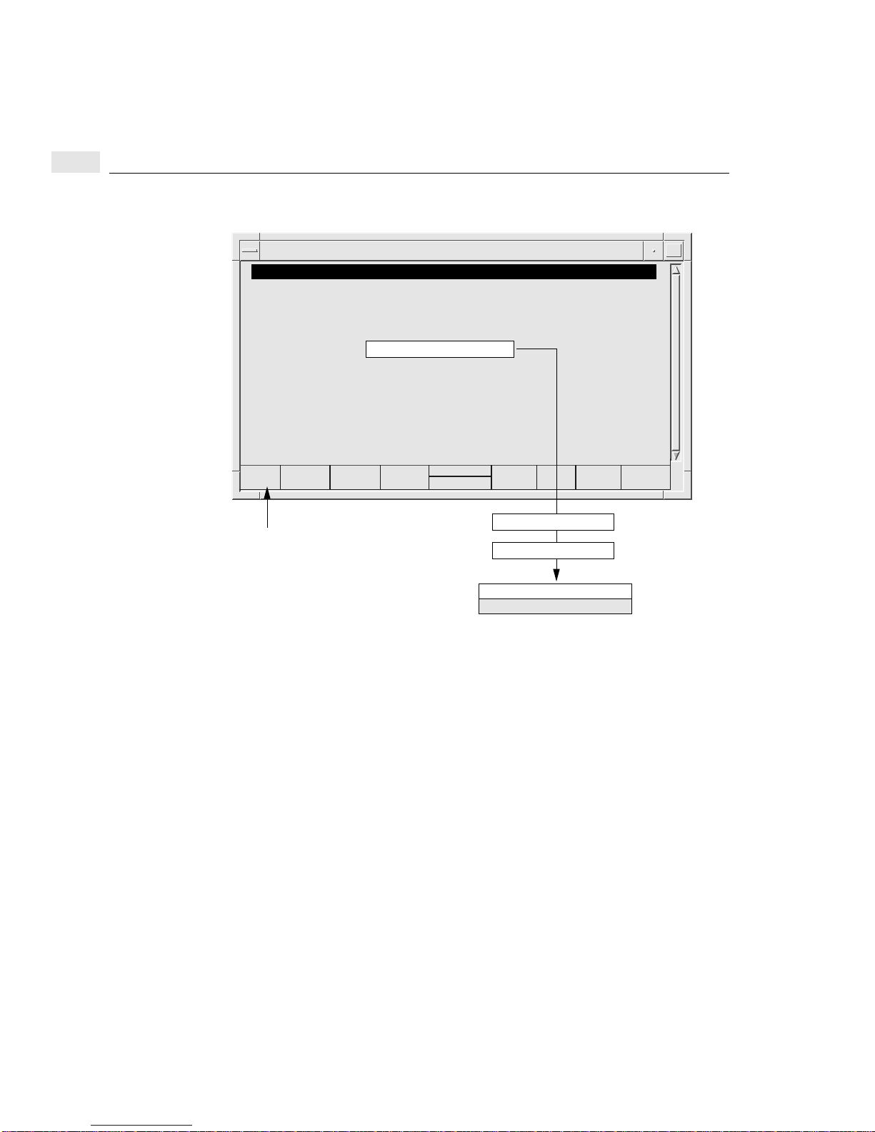
7
Configuring DNS/IP parameters
Configuring DNS/IP parameters
tsta195:root:/opt/dtcmgr/sbin
DTC Configuration Main Menu
Highlight an item and then press “Return” or “Select Item” (F4).
Add DTC Configuration ..
Modify DTC Configuration ....
Delete DTC Configuration ...
Modify Default Parameters ->
Help for Using DTCconfig
Help
Shell
Select
Item
tsta195:root
Exit
DTCconf
DTC NameClick here, or press F1 for online help
Rear Panel Configuration
Board = C or L
Action Menu (F5)
Configure DNS/IP Parameters
74
Use the DNS/IP Parameters Configuration to specify:
• the IP addresses for the DNS (Domain Name System) server
• the IP routing parameters
The DTC sends a DNS request to the DNS server whose IP address is specified. The
DNS server returns the IP address of the requested system. If you specify the IP
address of a system with the DTC connect command, DNS is not used.
The IP address format is xxx.xxx.xxx.xxx where xxx is a decimal number from 0
through 255. The IP address can be 0.0.0.0 but cannot be 255.255.255.255. The IP
address is unique on the network. An IP router allows connections to nodes on
different LAN networks. If an IP router is not defined, then connections cannot be
made to systems outside the local subnet.
Page 75
Configuring DNS/IP parameters
DNS/IP Parameters Configuration screen
tsta195:root:/opt/dtcmgr/sbin
DNS/IP Parameters Configuration
Fill in or modify the desired fields and then press “Perform Task” (F4).
Domain Name Service:
Default Server Address
Backup Server Address
Default Local Domain
IP Routing:
Default IP Router Address
Backup IP Router Address
Subnet Mask. . . . . . . . . . . . . . . .
Help
. . . . . . . .
. . . . . . . .
. . . . . . . .
15.128.128.93
15.128.128.50
mysys.mycorp
15.128.128.53
. . . . .
15.128.128.45
. . . . .
255.255.248.000
Select
Action
tsta195:root
(optional)
(optional)
(optional)
(optional)
(optional)
(optional)
Exit
Window
Enter the appropriate values in the provided fields and press the Perform Task (F4)
function key when you have finished. You are returned to the Rear Panel
Configuration screen.
7
DNS parameter definitions
Default Server
Address
Backup Server
Address
Default Local
Domain
Enter the IP address of the default server you want to use. A DNS server resolves
system names to IP addresses for the entire network. For example, if you are at a
terminal, you can enter the DTC connect command with a system name instead of
an IP address:
DTC> connect host1.hp.com
Enter the IP address of the DNS server to be used if the default DNS server is not
available.
Enter the default local domain that you want to use. The DTC uses the specified
local domain name to complete the Domain node name when necessary. If a
terminal user enters a node name without a period, the DTC will complete the node
name with the default local domain name. For example, if the Default Local
Domain is hp.com and a terminal user enters:
DTC> connect host1
the DTC will try to connect to host1.hp.com.
75
Page 76

7
Configuring DNS/IP parameters
IP Routing parameter definitions
Default IP Router
Address
Backup IP Router
Enter the IP address of the default router. The router routes outbound packets for
destinations which are not part of the local subnet.
Enter the IP address of the router to be used if the default IP router is not available.
Address
Subnet Mask Enter the subnet mask for this network. The subnet mask has an IP address format of
xxx.xxx.xxx.xxx where xxx is a decimal number between 0 and 255. It must have 255
in the first field. The subnet mask is an optional parameter.
The subnet mask provides a way to expand the network part of the IP address. The
subnet mask is used by IP to check if the datagram should be sent to the destination
without routing, or routed to a different destination network or subnetwork.
About subnets
A subnet is a portion of a network defined as a separate network. The subnet mask
specifies how much of the address to reserve for subdividing networks into
subnetworks. What defines a subnet is that all the bits in the IP address specified by
the subnet mask (that is all the bits set to 1 in the subnet mask) are the same for all
IP addresses in that subnet.
Example: If the subnet mask is:
76
255.255.255.224 (1111 1111 1111 1111 1111 1111 1110 0000)
then the right-most 5 bits of any address on the subnetwork indicate a node address.
Page 77

Configuring SNMP parameters
SNMP is an open-systems standard that allows a DTC to be interrogated by any
authorized SNMP network management workstation, for example a workstation
running HP OpenView Network Node Manager. Security is provided by
authorization filters which list the network management workstations that are
allowed to access the DTC.
The SNMP information about the DTC is stored in a MIB (management information
base). For example, the MIB contains information such as the physical location of
the DTC and whether the DTC should report unauthorized access attempts to the
SNMP manager. Two types of MIB are available: MIB-II allows the SNMP
manager to access the standard MIB objects; DTC MIB allows the SNMP manager
to access the standard MIB objects as well as HP-UX MIB objects.
DTC Manager’s dtcconfig utility provides two screens for SNMP configuration:
• Configure SNMP Authorization Filters—identifies the SNMP managers, the
information that can be requested and whether the managers have write access to
the SNMP MIB data.
• Configure SNMP/MIB Data Parameters—defines the SNMP-specific data to
be stored on the DTC.
Configuring SNMP parameters
7
77
Page 78
7
Configuring SNMP authorization filters
Configuring SNMP authorization filters
tsta195:root:/opt/dtcmgr/sbin
DTC Configuration Main Menu
Highlight an item and then press “Return” or “Select Item” (F4).
Add DTC Configuration ..
Modify DTC Configuration ....
Delete DTC Configuration ...
Modify Default Parameters ->
Help for Using DTCconfig
tsta195:root
Help
Shell
Select
Item
DTC NameClick here, or press F1 for online help
Rear Panel Configuration
Board = C or L
Action Menu (F5)
Configure SNMP
Authorization Filters
Exit
DTCconf
78
The Configure SNMP Authorization Filter Configuration screen enables you to:
• configure up to five SNMP filters
• define the SNMP manager(s) and the data they can request
• authorize write access to the SNMP MIB data
Use this screen to enter parameter values and then press the Perform Task (F4)
function key to return to the Rear Panel Configuration screen.
Page 79
SNMP authorization filter parameter definitions
Configuring SNMP authorization filters
7
SNMP Manager IP
Address
Enter the IP address of an SNMP manager that can monitor and control the DTC as
an SNMP network element.
A value of 0.0.0.0 in this field means that any SNMP manager that has the same
community name as the community name corresponding to this IP address can
access this DTC’s MIB parameters.
The IP address 255.255.255.255 is not valid in this field.
SNMP Authorization Filters Configuration screen
tsta195:root:/opt/dtcmgr/sbin
SNMP Authorization Filter Configuration
Fill in or modify the desired fields and then press “Perform Task”
SNMP Manager
IP Address
011.022.033.044
015.123.123.111
015.111.111.123
Help
SNMP Manager Community Name MIB Access MIB View
site 1_________________________
site 2_________________________
site 3_________________________
Shell
wally LAN board
Perform
Task
tsta195:root
Read Write
Read Only
Read Only
Default
Values
DTC MIB
DTC MIB
DTC MIB
Exit
Task
SNMP Manager
Community Name
Enter the name of the SNMP community to which the DTC belongs (all ASCII
characters are valid).
MIB Access Choose Read & Write or Read Only. These values determine the access rights of
the SNMP manager to the SNMP parameters of the DTC.
MIB View Choose DTC MIB or MIB-II. These values determine the subset of MIB objects
that the SNMP manager can access. Selecting DTC MIB enables the SNMP
manager to access both the SNMP MIB-II and HP-UX MIB objects.
1 If two SNMP authorization filters have the same SNMP manager community name they must also
1
have the same MIB access and MIB view values.
79
Page 80
7
Configuring SNMP MIB data
Configuring SNMP MIB data
Highlight an item and then press “Return” or “Select Item” (F4).
Help
Shell
tsta195:root:/opt/dtcmgr/sbin
DTC Configuration Main Menu
Add DTC Configuration ..
Modify DTC Configuration ....
Delete DTC Configuration ...
Modify Default Parameters ->
Help for Using DTCconfig
tsta195:root
Select
Item
Rear Panel Configuration
Board = C or L
Action Menu (F5)
Configure SNMP/MIB
Exit
DTCconf
DTC NameClick here, or press F1 for online help
Data Parameters
80
The Configure SNMP/MIB Data Configuration screen is used to specify the
SNMP-specific data to be stored on the DTC. This data can only be configured on
the DTC after a hardware reset and can be modified by an authorized SNMP
manager workstation after initial download.
1 Use this screen to enter SNMP data values and then press the Perform Task (F4)
function key to return to the Rear Panel Configuration screen.
2 You must reset the DTC when you modify these SNMP parameters.
3 Exit from dtcconfig and reset the DTC by typing the following command at the
shell prompt:
dtcreset
dtcname
Page 81
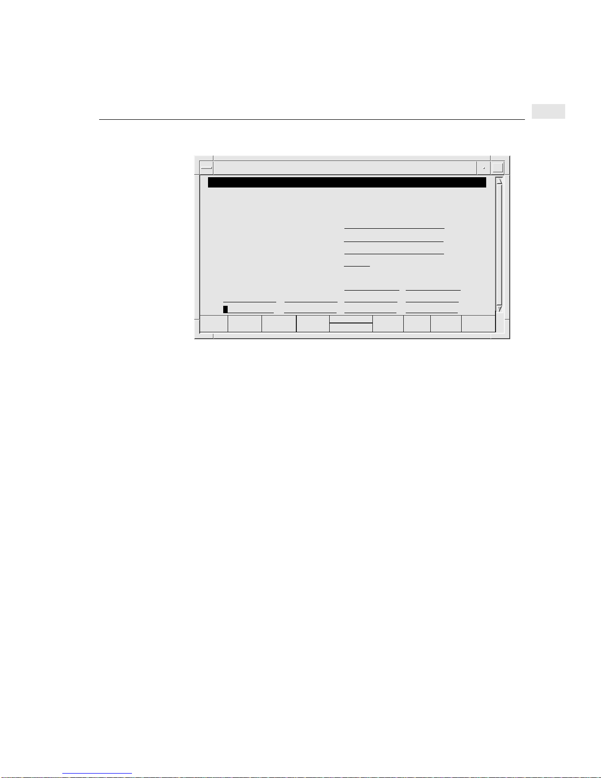
SNMP/MIB Data Configuration screen
tsta195:root:/opt/dtcmgr/sbin
SNMP/MIB Data Configuration
wally LAN board
Fill in or modify the desired fields and then press “Perform Task” (F4).
MIB II System Group Objects:
Contact Name . . . . . . .
Sys Name. . . . . . . . . . . . . . . . . . . . . . .
Sys Location . . . . . . . . . . . . . . . . . . . .
SNMP Enable Authentication Traps . .
HP-UX MIB Trap Destination (optional):
Trap Destination IP Addresses . .
003.003.003.003
. . . . . . . . . . . .
004.004.004.004 005.005.005.005 006.006.006.006
Configuring SNMP MIB data
Joe User__________________
anydtc____________________
site 1_____________________
Enabled
001.001.001.001 002.002.002.002
7
(optional)
(optional)
(optional)
Help
Shell
Perform
tsta195:root
Default
Values
Exit
Task
SNMP parameter definitions
Contact Name
Enter up to 255 ASCII characters. Contact the SNMP manager of your network to
find the name of the contact person to enter for this DTC. This optional field can
include information on how to contact the person as well as a name.
Sys Name Enter up to 255 ASCII characters if you want to use this optional field. Contact the
SNMP manager of your network to find the system name you should enter here.
This name will be used to identify the DTC as an SNMP node and is by convention
the same as the DTC node name.
Sys Location Enter up to 255 ASCII characters to specify the physical location of the DTC. This
is an optional field.
SNMP Enable
Authentication Traps
Set this optional field to Disabled or Enabled. Enabled means that the SNMP
process agent of the DTC can generate authentication failure traps.
Trap Destination IP
Address
Enter the IP addresses (non-broadcast) that designate the SNMP network
management stations on the network to which the DTC will send SNMP traps. If no
trap destination IP addresses are entered, the DTC will not generate any SNMP
traps.
81
Page 82
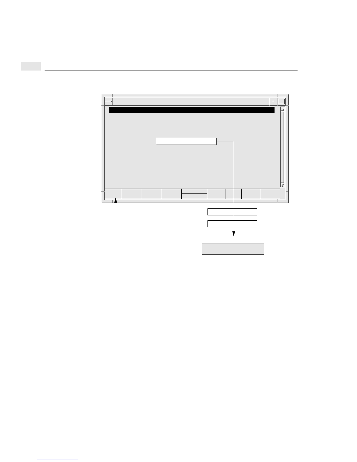
7
Configuring DTC management protocol parameters
Configuring DTC management protocol parameters
tsta195:root:/opt/dtcmgr/sbin
DTC Configuration Main Menu
Highlight an item and then press “Return” or “Select Item” (F4).
Add DTC Configuration ..
Modify DTC Configuration ....
Delete DTC Configuration ...
Modify Default Parameters ->
Help for Using DTCconfig
tsta195:root
Help
Shell
Select
Item
DTC NameClick here, or press F1 for online help
Rear Panel Configuration
Board = C or L
Action Menu (F5)
Configure DTC Management
Protocol Parameters
Exit
DTCconf
82
The Configure DTC Management Protocol Parameters screen is used to specify
DTC timing information for different LAN configurations.
1 Place an x or X to choose the set. The parameter values are defined according to
the set that you choose. These values are shown in table on the following page.
2 Set 1—HP default. Parameters designed for traffic over a LAN only.
Set 2—Parameters designed for traffic over a LAN with bridges.
Set 3—Parameters designed with alternative values for traffic over a LAN with
bridge.
3 When you have finished entering values, press the Done (F4) function key. You
are returned to the Rear Panel Configuration screen.
4 The DTC management parameters can not be modified dynamically. Exit from
dtcconfig and reset the DTC by executing the following command at the shell
prompt:
dtcreset
dtcname
Page 83
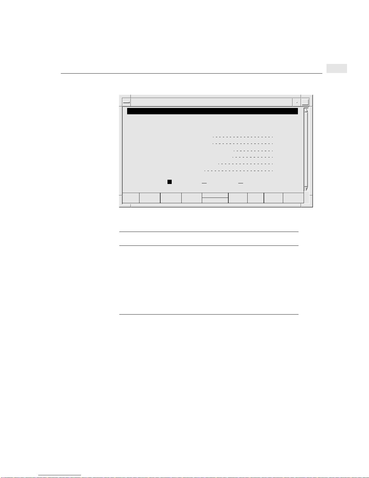
Configuring DTC management protocol parameters
Management Protocol Parameters Configuration screen
tsta195:root:/opt/dtcmgr/sbin
DTC Management Protocol Parameters Configuration
wally LAN board
Mark with an “x” the set of DTC management protocol parameters to configure.
Then press “Return” or “Done” (F4).
Maximum Timer (in tenths of seconds)
Minimum Timer (in tenths of seconds)
MP DTC Watchdog Timer (in tenths of seconds)
Maximum Number of Retries with Same Timer
Maximum Number of Retries
Management Protocol Packet Size
7
64
2
8
4
34
1024
Help
x
Select
Action
Set 2Set 1
tsta195:root
Set 3
Exit
Window
DTC management protocol timer sets
DTC Management Protocol Parameter Set 1 Set 2 Set 3
Maximum Timer (tenths of a second) 64 224 256
Minimum Timer (tenths of a second) 2 14 8
HP DTC Watchdog Timer (tenths of a second) 8 8 8
Maximum Number of Retries with Same Timer 4 3 3
Maximum Number of retries 34 15 18
Management Protocol Packet Size 1024 512 256
83
Page 84

7
Configuring DTC management protocol parameters
84
Page 85

Configuring DTC ports with dtcconfig
This chapter describes how to configure a port for the requirements of an attached
device. For example, if you want a printer on a certain port, you must ensure that the
port is set to be a printer port.
Configuring the port type
You can change a terminal port to a printer port (or vice versa) using the Change
Port Type option which you access via the Action Menu as illustrated below.
tsta195:root:/opt/dtcmgr/sbin
DTC Configuration Main Menu
Highlight an item and then press “Return” or “Select Item” (F4).
8
Help
Add DTC Configuration ..
Modify DTC Configuration ....
Delete DTC Configuration ...
Modify Default Parameters ->
Help for Using DTCconfig
tsta195:root
Shell
Select
Item
Exit
DTCconf
DTC NameClick here, or press F1 for online help
Rear Panel Configuration
Board = C or L
Action Menu (F5)
Change Port Type
85
Page 86
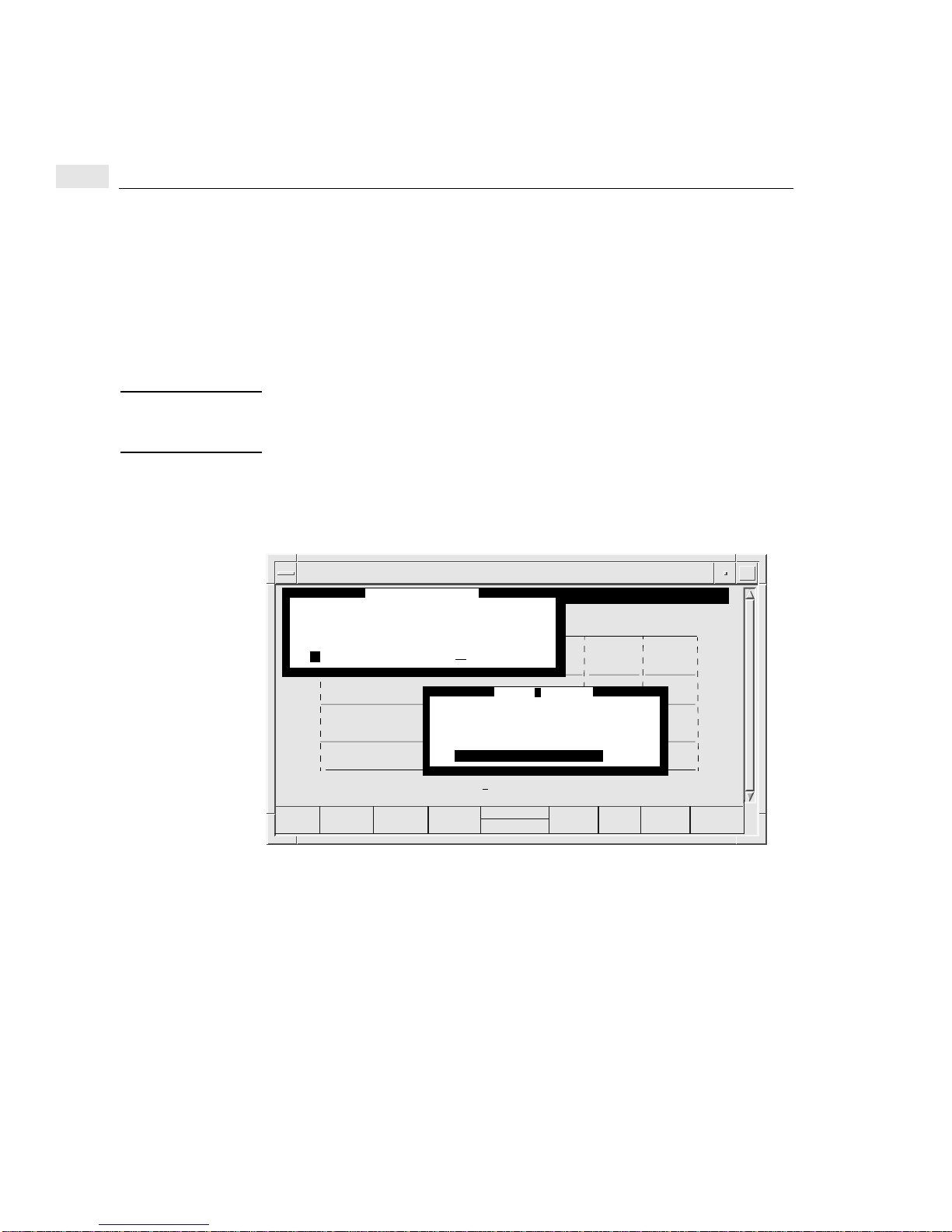
8
Configuring the port type
The steps are as follows:
1 Enter the board and port numbers at the Rear Panel Configuration screen.
2 Press the Action Menu (F5) function key and select Change Port Type.
The Change Port Type screen appears.
3 Indicate a printer or terminal port type by entering an x or X in the appropriate
field and press Return or the Done (F4) function key.
Note Change Port Type copies in the default port settings for the specified port type
(terminal or printer) when it is used. Therefore, any data that was in the port
configuration will be lost.
4 You can configure another board and port or exit from this Rear Panel
Configuration screen.
The Change Port Type screen
tsta195:root:/opt/dtcmgr/sbin
Change Port Type
wally board 1 port 19
Mark with an “x” the type of port to configure.
Fill in the DTC 72MX board and port fields and then press “Action Menu” (F5).
Then press “Return” or “Done” (F4).
0 T 2 T 4 T1 T 3 T 5 T
8 T 9 T 10 T
x
Terminal Printer
16 T 17 T 18 T 19 T 20 T 21 T 22 T 23 T
0 T 2 T 4 T1 T 3 T 5 T
8 T 9 T 10 T
16 T 17 T 18 T 19 T 20 T 21 T 22 T 23 T
Rear Panel Configuration
11 T 12 T 13 T 14 T 15 T
Configure Port Parameters ...
Enable Port Options ...
11 T 12 T 13 T 14 T 15 T
Copy
Paste
Change Port Type ...
6 T 7 T DIRECT
Action Menu
6 T 7 T
DIRECT
DIRECT
DIRECT
DIRECT
DIRECT
Board 3
Board 2
Board 1
Board 0
Board (L = LAN, or 0 - 3 = - board): Port (0 - 23):
Help
86
Done
1
tsta195:root
19
Exit
Window
Page 87

Configuring terminal and printer ports
Configuring terminal and printer ports
Once a port has been configured, this configuration can be copied and pasted to
other ports as described in chapter 9.
To modify several DTCs simultaneously, use the dtcmodifyconfs command as
described in chapter 10.
Note For the purposes of the procedures described in this chapter it is presumed that you
have added at least one DTC to the configuration and that it has at least one board in
it. It is also presumed that you are familiar with the basic use of the dtcconfig menus
and function keys as described in chapter 4.
Any changes you make to the port parameters take effect immediately. You do not
need to download the DTC. However, if any terminal users connected to the DTC
are running sessions, they will not see the changes until they close the current
sessions and start new sessions.
8
87
Page 88

8
Configurable port parameters
Configurable port parameters
The following port attributes are covered in this chapter.
• Port Parameters are listed below and explained in the section see “Configuring
terminal and printer port parameters” on page 91.
• Terminal or Printer Name or IP address
• Line Speed
• Attached Device
• Bits Parity (called “Parity” in version A.14.29)
• Number of Stop Bits (applies to version A.14.2C and later versions)
• Modem Behavior (for modem ports)
• Data Transfer Mode (applies to version A.14.2C and later versions for
terminal ports)
• Escape from Data Transfer character (for terminal ports)
• Maximum Number of Sessions (for terminal ports)
• Number of Systems Sharing Printer (for printer ports)
• Default Destination
• Initialization string
• Port Options are listed below and explained in the section see “Enabling port
options” on page 99.
• Enable Auto Speed/Parity Sensing (for terminal ports)
• Enable DTC User Interface Timeout (for terminal ports)
• Enable Port
• Enable Switching (for terminal ports)
• Enable Dedicated Printer (for printer ports)
• Enable Automatic Connection (for modem ports)
• Enable Hardware Handshake (for DTC 72MX and DTC 16TN)
• Enable Keep Alive (applies to version A.14.2C and later versions)
• Enable Flow Control (applies to version A.14.2C and later versions)
• Enable Port Config Saved In Binary (applies to version A.14.2C and later
versions)
88
Page 89

Configuring a port
1 Select Modify DTC Configuration from the dtcconfig main menu.
A pop-up window asks you for the name of the DTC whose configuration you
want to modify.
2 Type in a DTC name or press F1 and select a DTC from the list of existing DTCs.
Press Return or the Select Item (F4) function key.
The DTC Rear Panel Configuration screen appears.
3 In the Rear Panel Configuration screen, enter the board number to configure.
4 Use the arrow key to go to the port field and enter a port number according to the
DTC type:
• 0 through 15 - direct connect or modem ports for DTC 16TN
• 0 through 7 - direct connect ports for DTC 16 and DTC 48
• 0 through 5 - modem ports for DTC 16 and DTC 48
• 0 through 23 - direct connect or modem ports for DTC 72MX
5 Press the Action Menu (F5) function key and select one of the listed tasks.
Configuring a port
8
You are taken to the appropriate screen to enter new port values. The screen and
the information you provide for each task varies depending on the type of board
(direct-connect or modem) and type of port (printer or terminal) you have
chosen to configure.
The port configuration screen displays the current defaults being used. The
Configure Port screen and Enable Port Options screen allow you to choose
HP Defaults, User Defaults, or enter other values.
The screens are described in the rest of this chapter.
6 When you have finished making your changes, return to the Rear Panel
Configuration screen.
7 You can configure another board and port or press F8 to exit the Rear Panel
Configuration screen and return the dtcconfig main menu.
89
Page 90
8
Configuring a port
Example of a modified port: Board 3, Port 4
tsta195:root:/opt/dtcmgr/sbin
Rear Panel Configuration
Fill in the DTC 72MX board and port fields and then press “Action Menu” (F5).
0 T 2 T 4 T1 T 3 T 5 T
8 T 9 T 10 T
16 T 17 T 18 T 19 T 20 T 21 T 22 T 23 T
0 T 2 T 4 T1 T 3 T 5 T
8 T 9 T 10 T
16 T 17 T 18 T 19 T 20 T 21 T 22 T 23 T
Board (L = LAN, or 0 - 3 = board): Port (0 - 23):
11 T 12 T 13 T 14 T 15 T
11 T 12 T 13 T 14 T 15 T
wally
6 T 7 T DIRECT
6 T 7 T
LAN
DIRECT
DIRECT
DIRECT
DIRECT
DIRECT
Board 3
Board 2
Board 1
Board 0
4
Help
Shell
tsta195:root
Action
Menu
Exit
Task
90
Page 91
Configuring terminal and printer port parameters
Configuring terminal and printer port parameters
tsta195:root:/opt/dtcmgr/sbin
DTC Configuration Main Menu
Highlight an item and then press “Return” or “Select Item” (F4).
Add DTC Configuration ..
Modify DTC Configuration ....
Delete DTC Configuration ...
Modify Default Parameters ->
Help for Using DTCconfig
tsta195:root
Help
Shell
Select
Item
DTC NameClick here, or press F1 for online help
Rear Panel Configuration
Board = #, Port = #
Action Menu (F5)
Configure Port Parameters
8
Exit
DTCconf
1 Use the dtcconfig utility Action Menu to access either the Terminal Port
Parameters Configuration screen or the Printer Port Parameters
Configuration screen (shown on the following page).
2 Use the configuration screen to enter the appropriate parameter values (the
parameters are described on the following pages).
3 When you have finished entering values F4 to return to the Rear Panel
Configuration screen.
91
Page 92
8
Configuring terminal and printer port parameters
Terminal Port Parameters Configuration screen
Terminal Port Parameters Configuration
Fill in or modify the desired fields and then press “Perform Task” (F4).
Press “Help” (F1) to obtain the information or valid values for a field.
Terminal Name or IP Address . . . . . . . . . . . . . . . . . . . . .
Line Speed . . . . . . . .
Bits-Parity . . . . . . . .
Modem Behavior . . .
Escape from Data Transfer Character . . . . . . . . . . . . . . . .
Maximum Number of Sessions (1 - 5) . . . . . . . . . . . . . . . . 3
Default Destination (IP address or ARPA name) . . . . . . . .________________________
Initialization String (maximum of 16 characters) . . . . . . . ._____________(optional)
9600
8bits_None
None
tsta195:root:/opt/dtcmgr/sbin
KOKA board 0 port 0
Attached Device . . . .
Number of Stop Bits.
Data Transfer Mode ASCII
15.128.128.93
Terminal____
One
^K
(optional)
Help
Shell
Perform
Task
tsta195:root
Default
Values
Printer Port Parameters Configuration screen
tsta195:root:/opt/dtcmgr/sbin
Printer Port Parameters Configuration
Fill in or modify the desired fields and then press “Perform Task” (F4).
Press “Help” (F1) to obtain the information or valid values for a field.
Terminal Name or IP Address . . . . . . . . . . . . . . . . . . . . .
Line Speed . . . . . . . .
Bits-Parity . . . . . . . .
Modem Behavior . . .
Number of Systems Sharing Printer (1 - 5) . . . . . . . . . . . .
Default Destination (IP address or ARPA name) . . . . . . . .________________________
Initialization String (maximum of 16 characters) . . . . . . . _____________(optional)
Help
9600
8bits_None
None
Shell
KOKA board 0 port 0
Attached Device . . . .
Number of Stop Bits.
Perform
tsta195:root
Task
__________
Printer ____
One
3
Default
Values
(optional)
Exit
Task
Exit
Task
92
Page 93

Terminal and printer port parameter definitions
Configuring terminal and printer port parameters
8
Terminal/Printer
Name or IP Address
Enter up to 16 alphanumeric characters or an IP address in this field. The characters
can include hyphens (-) and underscores (_). The first character must be alphabetic.
This is an optional field that has no value by default.
By entering a name or IP address, you are naming or labeling the port, not the device
attached to it. If you disconnect the device and connect it to another port, the device
is associated with the name or IP address of the other port. If you want the device to
retain its name or IP address, you must reconfigure the ports accordingly.
Some key points to consider about using a port IP address:
• The port IP address must be on the same subnet as the DTCs IP address.
• If there is a port IP address for outgoing connections, it is used as the calling
address.
• If there is no IP address for the port, the DTCs IP address is used.
• You cannot use same port IP address for more than one DTC pooled port. Be
careful about the IP address when you copy and paste boards.
• The per port IP address feature can be used with the Telnet port identification
feature and the DTC Device File Access Utilities (DDFA). The port IP address
can be associated with a specific pty device file name. Together, these features
can be used to provide a pool of ports or identify a specific printer port to the
HP-UX spooler. DDFA is part of Internet Services. Refer to the DDFA
documentation for more information.
Line Speed Set the line speed to correspond to the line speed of the attached device. To select a
line speed, press the Help (F1) function key and a list is displayed. Line speed
choices are 300, 1200, 2400, 4800, 9600, 19200, and 38400 bits per second.
Highlight your choice and press Return or the Select Item (F4) function key.
The line speed default is 9600 baud. The 38400 bits per second speed applies only to
the DTC 16TN and DTC 72MX.
93
Page 94

8
Configuring terminal and printer port parameters
Attached Device Select the type of device physically attached to the port. This adapts the port
behavior to the requirements of the physically-attached device. To select the device,
press the Help (F1) function key and a list is displayed. Highlight your choice and
press Return or the Select Item (F4) function key.
Please refer to the HP DTC Technical Reference Manual (5961-9820)
The choices are as follows.
• Terminal—the default for direct connect and modem terminal ports
• Printer—the default for direct connect and modem printer ports
• HP 2334/35 Multiplexer
• US Modem—for a modem port with modem behavior set to Standard DCE,
DCE High, or DTE (see “Modem Behavior” on page 95).
• European Modem—for a modem port with modem behavior set to Standard
DCE, DCE High, or DTE.
• Data Switch
• US Modem IN OUT
• EU Modem In OUT
• Five Wires Modem.
Bits Parity Bits parity allows you to select the data length (not including start and stop bits) and
the parity you want to assign to the port. Data length is also known as number of bits
per character; these bits determine the number of received serial bits assembled to
form a character.
The possible values are :
7 bits data length with parity even
7 bits data length with parity odd
7 bits data length with parity forced to 0
7 bits data length with parity forced to 1
8 bits data length with parity none
8 bits data length with parity even
8 bits data length with parity odd
A setting of 8 bits data length with parity none is used by default.
94
Page 95

Configuring terminal and printer port parameters
Number of Stop Bits This setting determines the number of stop bits to be used for asynchronuous
characters. Possible values are :
1 stop bit
2 stop bits
The 2 stop bits option could be required for specific device, such as a bar code
reader. The setting 1 stop bit is used by default.
Modem Behavior If you have selected a direct connect port, modem behavior is not used and should
be set to None. The default is None.
Please refer to the HP DTC Technical Reference Manual (5961-9820) for simple
modem support.
If you have selected a port on a modem board or port group, select modem behavior
by pressing the Help (F1) function key. A list is displayed. Highlight your choice
and press Return or the Select Item (F4) function key.
The DTC checks device modem signals and sets up its own modem signals. You
may want to enable the automatic connection port option for this port. If enabled,
the DTC will establish a connection to the default destination as soon as it senses
modem signal activity. See “Default Destination (IP Address or Internet Name)” on
page 97. and see “Enable Keep Alive” on page 103.
8
Terminal modem ports
• None—use for a directly-connected terminal
• Standard DCE—use for a terminal connected to the DTC port via a modem/
multiplexer
• DCE high—use for a terminal connected to a DTC 16TN or DTC 72MX port
via a modem/multiplexer, and where you need an indefinite time-out before
pressing Return to connect to the DTC user interface
• DTE—use when the connection to the terminal is initiated by the host
95
Page 96

8
Configuring terminal and printer port parameters
Printer modem ports
• None—use for a directly-connected printer.
• Standard DCE—use for a modem-connected printer, where a link is made
at the device.
• DCE high—use for a terminal connected via a modem/multiplexer.
• DTE—use when the connection to the terminal is initiated by the host.
Data Transfer Mode Specifies the data transfer mode to be used when opening the connection on the port.
Possible values are :
ASCII
BINARY
If BINARY is used, the DTC does not detect special characters received from the
device; all received characters from the device are sent to the system without
interpretation.This is also known as transparent mode.
The setting ASCII is used by default.
Escape From Data
Transfer Character
Maximum Number of
Sessions
96
Enter the ASCII character you want to use as the escape character that signals when
to escape from the data transfer process. Non-displayable ASCII characters are
specified in caret-character (^character) format. The literal caret (^) and backslash
(\) are escaped with a backslash. This field must be filled. The default escape (from
data transfer) character is ^K (Ctrl-K).
The escape from data transfer character is used at a terminal to switch from the host
system to the DTC terminal user interface. This value applies only to terminal ports
for which switching is enabled (see “Enable Switching” on page 102).
If switching is enabled when the DTC is configured, you can logon to a terminal.
Press any key on the terminal to get a DTC prompt. You can then logon to your
system. Later, if you wish to leave your system but not log off, you enter the escape
from data transfer character (Ctrl-K). You see the DTC prompt again and can enter
a DTC user terminal interface command. You can even connect to another system.
The number of systems you can connect to is determined by the Maximum
Number of Sessions.
Specify a value between 1 and 5. The maximum number of sessions is the greatest
number of system connections allowed on a terminal at any one time. This value
applies only to terminal ports for which switching is enabled.
Page 97

The default is 3 sessions per port.
Configuring terminal and printer port parameters
8
Number of Systems
Sharing Printer
Default Destination
(IP Address or
Internet Name)
Specify a value between 1 and 5. This field applies only to printer ports for which
the dedicated printer is disabled. The number of systems sharing printer is the
greatest number of systems able to use the printer port at any one time.
The dedicated printer option is enabled or disabled from the Enable Port Options
menu. By default, the dedicated printer option is disabled.
The default is 3 systems sharing a printer.
Total number of sessions and shared printers
DTC 16TN DTC 16 DTC 48 DTC 72MX
Maximum number
of sessions
Printer sharing 5 x 16 = 80 5 x 16=80 (6 x 8)+40=88 5 x 72 = 360
Enter one of the following in this field.
• Nothing—no system is identified (this is the default).
• The Internet Services node domain name—any number of non-empty fields
separated by periods (.). Each field may contain alphanumeric characters and
hyphens (-).
5 x 16 =80 5 x 16=80 (6 x 8)+40=88 5 x 72 = 360
• An IP address.
97
Page 98

8
Configuring terminal and printer port parameters
The Default Destination field specifies the system for the device connected to the
port. How you define the Default Destination depends on the type of device and the
port options that are enabled or disabled.
Other Port
Settings
Switching
disabled
Switching
enabled
Automatic
connection
enabled
Dedicated
printer enabled
* You can only use a system name here if a DNS server has been configured on the DTC
Type of
Port
Direct
connect
terminal
Direct
connect
terminal
Modem
terminal
Printer IP address of system
What to Enter for
“Default Destination”
IP address of system
or
system name*
empty You must type C followed by
IP address of system
or
system name*
IP address of system
or
system name*
or
system name*
Result
The DTC connects you to this
system when it senses a
carriage return at the terminal.
the IP address or name of the
system to which you want to
connect.
If you type C, without
specifying a system, you are
connected to the default
destination.
The DTC connects you to this
system when it detects modem
or keyboard activity.
The printer is only available to
the “default destination”
system.
For information on switching, automatic connection, and dedicated printers, see
“Enable terminal or printer port options parameter definitions” on page 101.
Initialization String Enter up to 16 ASCII characters to specify the initialization string. Non-displayable
ASCII characters are specified in caret-character (^character) format. For example,
specify ^M^J for Ctrl-M and Ctrl-J. The literal caret (^) and backslash (\) are
escaped with a backslash. This field is optional and the default is empty.
If specified, the initialization string is the string to be sent to the connected terminal
or printer port immediately after one of the following tasks:
• resetting a port
• closing a session on a host and returning to the DTC user interface
• logging into a system and typing the escape from data transfer character
• establishing a connection to the DTC user interface for modem connections:
the initialization string is sent when all the modem signals are up.
98
Page 99
Enabling port options
Help
Enabling port options
tsta195:root:/opt/dtcmgr/sbin
DTC Configuration Main Menu
Highlight an item and then press “Return” or “Select Item” (F4).
Add DTC Configuration ..
Modify DTC Configuration ....
Delete DTC Configuration ...
Modify Default Parameters ->
Help for Using DTCconfig
tsta195:root
Shell
Select
Item
DTC NameClick here, or press F1 for online help
Rear Panel Configuration
Board = #, Port = #
Action Menu (F5)
Enable Port Options
8
Exit
DTCconf
1 Use thedtcconfig utility Action Menu to access the Enable Port Options screen
(as shown above).
2 Enter the appropriate values and press the F4 to return to the Rear Panel
Configuration screen.
99
Page 100
8
Enabling port options
Enable Terminal Port Options screen for a DTC 16TN
tsta195:root:/opt/dtcmgr/sbin
Enable Terminal Port Options
Mark with an “x” the port option to enable.
Then press “Done” (F4).
Fill in the DTC 16TN board and port fields and then press “Action Menu” (F5).
Enable Auto Speed/Parity Sensing
Enable DTC User Interface Timeout
x
Enable Port
|
0 T
x
Enable Switching
Enable Automatic Connection
x
Enable Keep Alive
Enable Port Config Saved in Binary
1 P
|
8 T
9 T
|
-------------------------------------------------------------------
|
|
Rear Panel Configuration
2 T
3 P 4 T 5 T 6 T 7 T
10 T
11 T 12 T 13 T 14 T 15 T
x
Enable Flow Control
LAN
Action Menu
Configure Port Parameters . . .
Enable Port Options ...
Copy
Paste
Change Port Type . . .
Change Port Type ...
|
DIRECT
|
DIRECT
----------------|
|
|
|
|
|
DIRECT
|
DIRECT
DIRECT
Board (C = CPU/LAN, or 0 - 5 = board): Port (0 - 7):
Help
tsta195:root
Direct Connect Printer Port Options: for a DTC 16TN
tsta195:root:/opt/dtcmgr/sbin
Enable Printer Port Options
Mark with an “x” the port option to enable.
Then press “Done” (F4).
Fill in the DTC 16TN board and port fields and then press “Action Menu” (F5).
x
Enable Port
Enable Dedicated Printer
Enable Automatic Connection
|
0 T
x
Enable Keep Alive
Enable Port Config Saved in Binary
1 P
|
8 T
9 T
|
-------------------------------------------------------------------
|
|
Board (C = CPU/LAN, or 0 - 5 = board): Port (0 - 7):
Help
Rear Panel Configuration
juin
2 T
3 P 4 T 5 T 6 T 7 T
x
Enable Flow Control
10 T
11 T 12 T 13 T 14 T 15 T
LAN
tsta195:root
Action Menu
Configure Port Parameters . . .
Enable Port Options ...
Copy
Paste
Change Port Type . . .
Change Port Type ...
1
|
DIRECT
|
DIRECT
----------------|
|
1
|
|
|
|
DIRECT
|
DIRECT
DIRECT
Exit
Task
Exit
Task
100
 Loading...