

Page 1

Errata
Title & Document Type:
Manual Part Number:
Revision Date:
HP References in this Manual
This manual may contain references to HP or Hewlett-Packard. Please note that HewlettPackard's former test and measurement, semiconductor products and chemical analysis
businesses are now part of Agilent Technologies. We have made no changes to this
manual copy. The HP XXXX referred to in this document is now the Agilent XXXX.
For example, model number HP8648A is now model number Agilent 8648A.
About this Manual
We’ve added this manual to the Agilent website in an effort to help you support your
product. This manual provides the best information we could find. It may be incomplete
or contain dated information, and the scan quality may not be idea l. If we find a better
copy in the future, we will add it to the Agilent website.
Support for Your Product
Agilent no longer sells or supports this product. You will find any other available
product information on the Agilent Test & Measurement website:
www.tm.agilent.com
Search for the model number of this product, and the resulting product page will guide
you to any available information. Our service centers may be able to perform calibration
if no repair parts are needed, but no other support from Agilent is available.
Page 2
8756A
OPERATION
MANUAL
SCALAR
This
manual
Scalar
2317A.
For
refer to
in Section I.
Network
additional
INSTRUMENTS
NETWORK
applies directly to
SERIAL
Analyzer
information
NUMBERS
having
ANALYZER
HP
serial
about
COVERED
Model
number
serial
BY
8756A
prefix
numbers,
MANUAL
©
Copyright
1400
FOUNTAIN
MANUAL
PART NO.
08756-90013
HEWLETT-PACKARD
GROVE PARKWAY,
COMPANY
SANTA
ROSA,
CA
95404
Ff/;'1
a:~
1983
U.S.A.
Printed:
AUGUST
1983
HEWLETT
PACKARD
Page 3
INTRODUCTION
This
Service
It
preparation
both
with
The
make
(HP-IB)
individual
In
operate
understanding
operator
is
Following
Note(s)
specific
Network
the
operation
Operation
Manual
contains
manual
the
8756A.
convenience
it
well
test
Manual
as
a
1escriotion
for
use,
and
automatic
and
suited
eauioment
needs.
OPERATING INFORMATION
the
8756A
of
errors,
not
already
the
and
hiahly
OPERATING INFORMATION,
Programming
apPlication
Analyzer
8756A.
A
Programminq
(using
a
reference
accuracy
for
in
this
and
and
an
external
is
suPplied
of
as
well
test
a
variety
applications,
you
either
section
should
skilled
Notes.
(Basic
8350B
Sweep
Note,
document
the
instrument,
as
information
applications,
of
the
of
will
the
find
local
will
be
the
in
the
An
OPerating
Network
Oscillator)
on
controller).
with
the
for
8756A
bench
which
the
or
remote
help
first
to
stop
operation
you
will
Measurements
the
other
8756A
the
on
Scalar
top
may
information
eliminate
Note
hand,
Operating
Instrument
specifi~ations,
using
and
the
shoul~
Network
and
automatic
be
tailored
needed
mode.
for
of
find
A
a
multitude
the
operator
the
8756A.
Operatinq
illustrates
of
Usina
locallv
8756A
apPlies
and
Operator.
and
8756A
be
kept
Analyzer
to
your
to
thorough
a
Scalar
operating
to
remote
in
of
who
Under
on
specific
8756A's
Programming
teaching
controller.
remote
illustrated.
It
is
a
condensed
characteristics.
the
Quick
HP-IB
Reference
operating
you
how
capabilities,
The
information
Notes,
to
remotelv
It
Quick
Reference
descriPtion
Once
you
Guide
the
is
Introductorv
meant
HP-IB,
of
are
familiar
will
provide
without
program
to
be
and
Guide
the
8756A's
explanations.
Operating
your
an
introduction
use
is
controller
with
a
summarv
Guide
instrument
of
the
controller
HP-IB
oPerating
proaramming
of
all
focuses
with
to
a
the
independent.
the
8756A,
of
the
Page 4
INTRODUCTION
CONTENTS
GENERAL
INFORMATION
Introduction
Soecifications
Safety
Considerations
Instruments
Description
Options
. . . . . . . • . .
Accessories
Equipment
Equipment
Reauired
Available
Hewlett-Packard
8756
System
Covered
Supplied
Interface
•.
....
Interface
INSTALLATION
Introduction
Initial
Preparation
Storage
Inspection
and
• . .
for
Use
Shipment
OPERATION . • . . •
OPERATING INFORMATION
Introduction
Operating
Operating
Operator's
Error
Front
Soft
Rear
HP-IB
CRT
HP
HP
Front
Messages
Panel
Key
Panel
Ooeratinq
Graphics
8756!\.
8756A
Panel
Operator's
Soft
Kev
Characteristics
Instructions
Operating
Modified
Status
Menu Map . . . . . . • .
. . . .
Checks
. . . . .
Operating
Operating
Features
. • . . . . . . • . . . . . • .
ASCII
Byte
Kev
Codes
Check
by
Manual
• . .
.•.
but
not
snoplied
. . . . • . . . . . . .
Bus
(HP-IB)
. . • . . .
. . . . . . • • . . . • . . . . .
..•...
Features
•............
Features
Features
. . .
Character
DescriPtions
Set
..•
. . . . . . . . . . • . .
..•...
l-1
1-1
l-1
1-2
1-2
1-2
1-3
l-4
1-4
l-4
1-~
l-5
/.-1
2-1
2-l
2-l
2-8
3-i
3-1
3-l
3-l
3-2
3-2
3-2
3-3
3-14
3-24
3-26
3-44
3-45
3-4n
3-4~
3-4n
3-53
OPERATING
PROGRAMMING
NOTES
NOTES
Page 5
Model8756A
Installation
SECTION II
INSTALLATION
2-1.
2-2.
tions
Analyzer
includes information
damage
ment, packaging, storage,
2-3.
2-4.
damage.
material is
contents
completeness
checked mechanically
tents
Figure
performance are given in
instrument
mance
V
INTRODUCTION
This
section provides installation instruc-
for
the
Model
and
its accessories.
8756A
about
claims,
INITIAL INSPECTION
Inspect
If
of
preparation
the
the
shipping
damaged
the
shipment
and
shipping
container
it
should
the
instrument
and
of
the
shipment
1-1.
Procedures for checking electrical
does
not
should
pass the electrical perfor-
tests, refer to the adjustments
of
this manual.
If
a circuit
Scalar
This
Network
section also
initial inspection,
for using the instru-
and
shipment
container
or
cushioning
be kept until the
have
been
checked for
has
electrically.
be
Section
The
as shown
IV.
in
Section
malfunction
been
If
is suspected, refer to troubleshooting information
Section VIII.
above electrical tests,
are
incomplete,
damage
Packard
damaged,
signs
of
Hewlett-Packard
materials for carrier's inspection.
will arrange for
waiting for claim
2-5.
PREPARATION FOR USE
If
the
instrument
or
if
or
if
or
defect, notify the nearest Hewlett-
office.
or
If
the
cushioning
the
does
the
shipment
there
is
shipping
material shows
not
pass the
contents
mechanical
container
stress, notify the carrier as well as the
office.
repair
Keep
or
replacement without
the
The
shipping
HP
office
settlement
for
con-
in
the
in
is
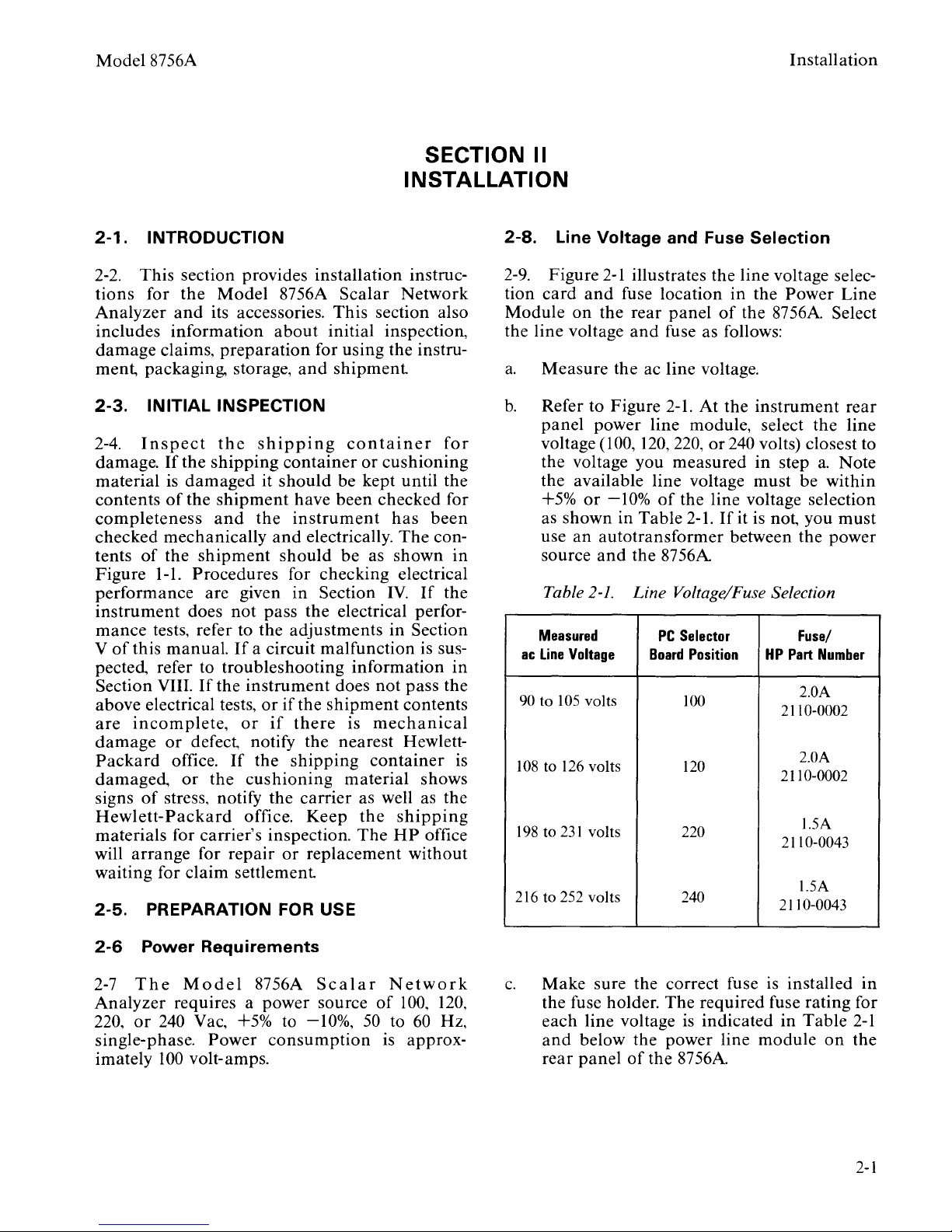
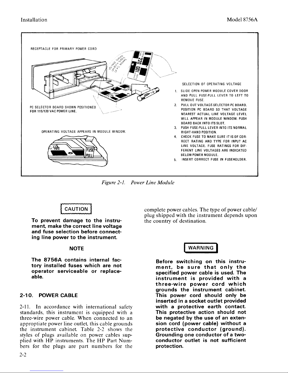
2-8.
2-9.
tion
Module
the line voltage
a.
b. Refer to Figure
Line
Voltage
Figure
card
and
on
the
Measure
panel
voltage
power line module, select the line
(100,
2-1
the ac line voltage.
and Fuse
illustrates the line voltage selec-
fuse location
rear
panel
and
fuse as follows:
2-1.
120,
220,
in
of
At
the
or
240 volts) closest to
the voltage you measured
Selection
the Power Line
the
87
56A
instrument
in
step
the available line voltage must be within
or
+5%
-10%
as shown in Table
use
an
autotransformer
Voltage
105
volts
126
231
and
2-1.
volts
volts
source
Table
Measured
ac
Line
90 to
108
to
198
to
216 to 252 volts
of
the line voltage selection
2-1.
If
it is not, you
between the power
the
87
56
A
Line Voltage/Fuse Selection
PC
Selector
Board
Position
100
120
220
240
HP
Part
2110-0002
2110-0002
2110-0043
2110-0043
a.
Fuse/
Number
2.0A
2.0A
1.5A
1.5A
Select
rear
Note
must
2-6
Power
2-7
The
Analyzer
220,
or
single-phase. Power
imately
Requirements
Mode
I 8756A
Seal
requires a power source
240 Vac, +5% to
-10%,
consumption
100
volt-amps.
a r
Network
of
100,
50
to 60 Hz,
is approx-
120,
c.
Make
the fuse holder.
each line voltage
and
below the power line
rear
panel
sure the correct fuse is installed
The
required fuse rating for
is
indicated in Table
of
the 8756A
module
on
in
2-1
the
2-1
Page 6
Installation
Model8756A
RECEPTACLE
PC
SELECTOR
FOR
115/120
OPERATING
FOR
BOARD
VAC
PRIMARY
SHOWN
POWER
VOLTAGE
LINE.
POWER
CORD
POSITIONED
APPEARS
\
IN
MODULE
Figure 2-1.
WINDOW.
Power
Line
Module
SELECTION
1.
SLIDE
AND
REMOVE
2.
PULL
POSITION
NEAREST
WILL
BOARD
3.
PUSH
RIGHT-HAND
4.
CHECK
RECT
LINE
FERENT
BELOW
5.
INSERT
OF
OPERATING
OPEN
POWER
PULL
FUSE-PULL
FUSE.
OUT
VOLTAGE-SELECTOR
PC
BOARD
ACTUAL
APPEAR
IN
LINE
MODULE
INTO
LEVER
POSITION.
TO
MAKE
AND
FUSE
VOLTAGES
MODULE.
BACK
FUSE-PULL
FUSE
RATING
VOLTAGE.
POWER
CORRECT
MODULE
LEVER
SO
LINE
ITS
SLOT.
SURE
TYPE
RATINGS
FUSE
VOLTAGE
COVER
TO
PC
THAT
VOLTAGE
VOLTAGE
WINDOW.
INTO
ITS
IT
IS
FOR
INPUT
ARE
INDICATED
IN
FUSEHOLDER.
DOOR
LEFT
BOARD.
LEVEL
PUSH
NORMAL
OF
COR-
AC
FOR
DIF-
TO
To
prevent
ment,
make
damage
the
correct
to
the
line
and fuse selection before connecting
line
power
to
the
instrument.
NOTE
The
8756A
tory
installed fuses
operator
contains internal fac-
which
serviceable
or
able.
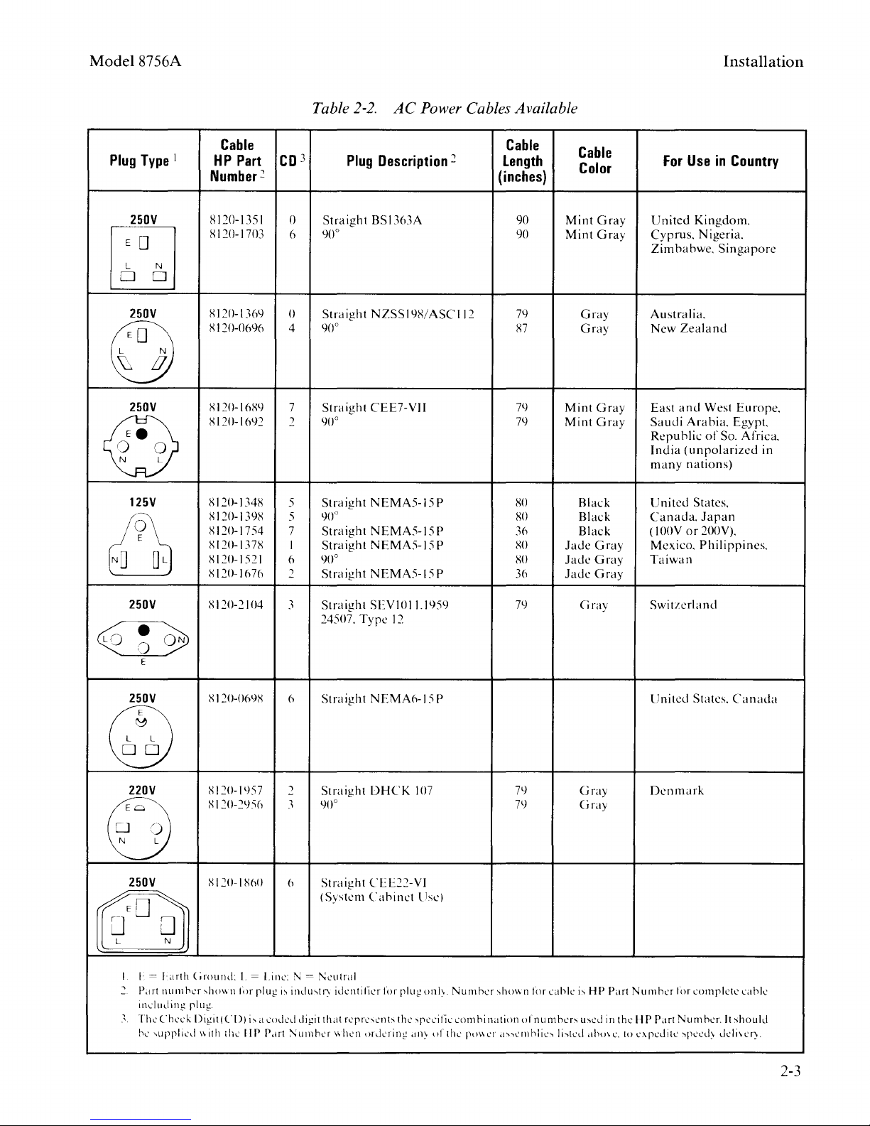
2-10.
2-11.
standards,
three-wire
approptiate
the
styles
plied
bers for
POWER CABLE
In
accordance
this
instrument
power
power
instrument
of
plugs available
with
HP
instruments.
the
plugs
with
international
is
cable.
When
line outlet. this
cabinet
Table
on
The
are
part
equipped
connected
power
numbers
instru-
voltage
are
not
replace-
safety
with a
cable
grounds
2-2 shows
cables sup-
HP
Part
Num-
for
to
an
the
the
complete
plug
the
power
shipped
country
Before
ment,
with
of
switching
be
specified
instrument
three-wire
grounds
This
power
inserted in a
with a protective
This
protective
be
negated
sion cord
protective
Grounding
conductor
protection.
cables.
The
the
instrument
type
of
destination.
WARNING
sure
power
is
power
the
instrument
cable is used.
provided
on
that
cord
I
this
only
cord should only be
socket
outlet
earth
action should
by
the
use
of
an exten-
(power
conductor
one
outlet
cable)
conductor
is
not
without
(ground).
sufficient
power
depends
instru-
the
The
with
which
cabinet.
provided
contact.
not
of a two-
cable/
upon
a
a
2-2
Page 7
Mode18756A
Table
2-2.
AC
Power Cables Available
Installation
Type
250V
1
Plug
~
250V
Sl20-1369
s 120-069()
u
250V
@
125V
t91
SI20-16R9
Xl20-lf>92
RI20-134S
R 120-139S
s 120-1 7 54
S 120-137S
Sl20-1521
Xl20-1676
Cable
HP
Part
Number
Rl20-1351
Sl20-1703
3
co
2
0
6
()
4
7
2
5
5
7
I
6
2
Plug
Straight
90°
Straight
90°
Straight
90°
Straight
90°
Straight
Straight
90°
Straight
Description
BSI363A
NZSSI9R/ASCII2
CEE7-VJJ
NEMA5-15P
NEMA5-15P
NEMA5-15
NEMA5-15P
2
P
Length
(inches)
90
90
79
S7
79
79
so
xo
36
RO
so
36
Cable
Cable
Color
Mint
Mint
Gray
Gray
Mint
Mint
Black
Black
Black
Jade
Jade
Jade
Gray
Gray
Gray
Gray
Gray
Gray
Gray
For
Use
United
Zealand
and
(unpolarized
lOOV
Kingdom.
Nigeria.
Arabia.
nations)
States.
or
Cyprus.
Zimbabwe.
Australia.
New
East
Saudi
Republic
India
many
United
Canada.
(
Mexico.
Taiwan
in
Country
Singapore
West
Europe.
Egypt.
of
So.
Africa.
Japan
200V).
Philippines.
in
250V
~
E
250V
@
220V
EJ
250V
I
I·=
Ltrth
~
P.trt
nllmhcr
incllldin!,!
'
ThL'
Chcc
he·
k
'llpplicd
s 120-2104
S I 20-06lJX
Xl20-1957
s 120-29:'i6
X 120-1
Cirollnd:
,Jwv.n
plut!
[)igi
t ( C
v.ilh
X60
I.=
Line:
lin
pill!,!
l))
i"
a coded digit that
the
liP
P.trt
3
()
:\I=
i'
indll\tr\
:--.:umhcr
Straight
24507.
Straight
Straight
900
Straight
(System
1\:clltral
idcntilicr
rcrrc-..cnh
v.hcn
SEVIOII
Type
12
NEMA6-15P
DHCK
CEE22-VI
Cabinet
for
pill!,!
the
<)rdcring
107
lise)
"PLL'i
.ttl\
195l)
on!\
ufthc
Nurnhcr
fiL·
con1
hi
puv.cr
'hown
nation
.t"ctnhlic,
7l)
79
79
for
of n urn
cahlc
her-.,
Ji,tcd
(iray
Gray
Gray
i'
H P
u~cd
.thmc.
Switzerland
United
Denmark
Part
Nllrnhcr
in
the H P Part N
to
expedite
States.
lin
complete
un1
'peeL!\
her.
Canada
It
~hou
deli\
cahlc
ld
cry.
2-3
Page 8
Installation
2-12.
tor
is
offset
the
grounding
pin
of
pin.
the
The
8756A from a two-contact
grounding
feature
may
be
three-prong to two-prong
tors only,
necting
HP
the
Part
green
Number
wire
ground.
three-prong
When
outlet,
the
connec-
operating
protective
preserved by using a
adapter
of
(USA connec-
1251-0048)
the
adapter
and
con-
Model8756A
the
to
2-13.
2-14.
control with
bus
The
and
on
may
HP-IB Address Selection
When
refers to
8756A is preset
the 8756A is used
the
HP-
IB, the controller
the
8756A by
in
firmware to address
is differentiated from
the
bus
by this address.
be
modified
by a front
an
any
The
under
HP-IB
other
HP-IB
panel
remote
on
the
"address".
16,
instrument
address
SHIFT
function.
2-15. Twenty-nine different address codes are
29).
The
available (I to
8756A is
the factory preset to address
8756A instruments,
read
by the processor from firmware
tial power
remain
resetting
[LOCAL] function.
on
in effect until the address is
through
read directly from
[SHIFn
is
then
address
played,
to
terminate
show
[LOCAL].
displayed
must
enter
the
new
be
the
the entry.
not affected by
by a
PRESET
the
only. This
the
The
the
The
on
the
changed
new
address
The
HP-
IB address.
turning
command.
HP-IB
front
HP-IB
front
current
from
the
HP-IB
CRT.
display
LINE
shipped
16.
In
all
standard
address will be
upon
address will
changed
panel
address
panel
[SHIFn
may
by pressing
HP-IB address
If
the
that
which
and
press
should
This
address is
switch off,
from
ini-
by
be
HP-IB
is
dis-
[ENn
now
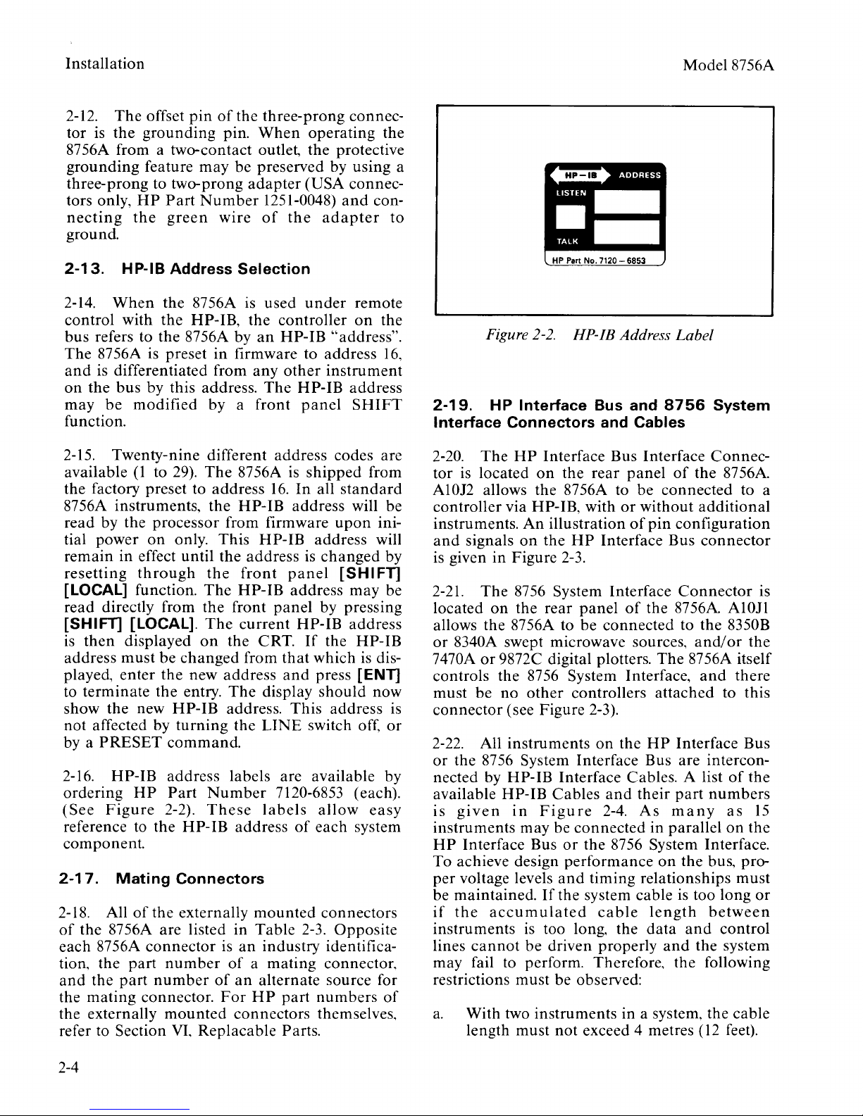
2-16. HP-IB address labels are available by
ordering
(See
reference to the HP-IB address
HP
Figure
Part
2-2).
Number
These
7120-6853 (each).
labels
allow
of
each system
easy
component.
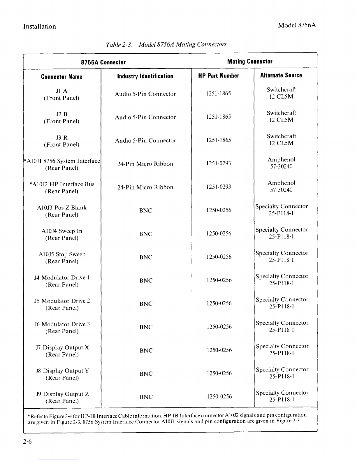
2-17.
2-18. All
of
each
tion, the
and
the
the externally
refer to Section
Mating
Connectors
of
the externally
the 8756A are listed in
8756A
the
mating
connector
part
part
number
connector.
number
of
mounted
VI.
Replacable
is
an
of a mating
an
For
connectors themselves.
mounted
Table
connectors
2-3.
Opposite
industry identifica-
connector.
alternate source for
HP
part
numbers
Parts.
of
or
Figure
2-19.
Interface Connectors and Cables
2-20.
HP Interface Bus and
The
tor is located
A10J2 allows the 8756A to
controller via
instruments.
and
signals
is given
2-21.
located
The
on
allows the 8756A to
or
8340A swept microwave sources,
7470A
or
controls the 8756 System Interface,
be
must
connector
2-22. All
or
the 8756 System Interface Bus are intercon-
nected by
available HP-IB Cables
is
given
instruments may be
HP
Interface Bus
To achieve design
per
voltage levels
be maintained.
if
the
accumulated
instruments
cannot
lines
2-2.
HP-IB Address Label
HP
Interface Bus Interface
on
the
rear
panel
in
Figure
An
on
HP-IB, with
illustration
the
HP
2-3.
or
of
Interface Bus
8756 System Interface
the rear
panel
be
connected
of
9872C digital plotters.
no
other
controllers
(see Figure 2-3).
instruments
HP-
IB Interface Cables. A list
on
the
and
in
Figure
2-4.
connected
or
the 8756 System Interface.
performance
and
timing relationships
If
the system cable is too long
cable
is
too long, the
be driven properly
8756
System
Connec-
of
the 8756A.
be
connected
without
pin
configuration
additional
to a
connector
Connector
the 8756A. A10Jl
to the 8350B
and/
or
The
8756A itself
and
there
attached
HP
Interface Bus
to this
of
their
part
numbers
As
many
in
parallel
on
the bus, pro-
as
on
must
length
data
and
between
and
control
the system
is
the
the
15
the
or
may fail to perform. Therefore. the following
must
restrictions
a.
With two instruments in a system, the cable
length must
be observed:
not
exceed 4 metres (12 feet).
2-4
Page 9

Model8756A
Installation
GROUNDED
TERMINATION
OTHER
TWISTED
NEAR
WIRE
PAIR
OF
OF
P/0
TWISTED
P/0
TWISTED
P/0
P/0
P/0
P/0
8756
SIGNAL
TWISTED
TWISTED
TWISTED
TWISTED
SYSTEM INTERFACE CONNECTOR
and HP INTERFACE BUS CONNECTOR
(as viewed from rear
GROUND
PAIR
WITH
PAIR
WITH
PAIR
WITH 9 '-..._
PAIR
WITH
PAIR
WITH
PAIR
WITH 6 --
~::~;~~
LD106
~
11
\\
10
~
-
8
~
7 -
~
L
REN
/-:/16
I I
24
23
"'\
""'
22
21
20
19
18
17
:~
of
instrument)
-
7
6
--
:
~
~
~
~
A1
OJ1
A1
OJ2
(CONNECTED
EARTH
GROUND)
SHIELD
LATN
L
SRQ
LIFC
L
NDAC
LNRFD
LDAV
LEOI
LDI04
LOI03
TO
HP-IB
Logic
True
(low)
NOTE:
Mnemonics
Interface;
LATN
LDAV
L
LEOI
LIFC
LNDAC
LNRFD
LREN
LSRQ
Levels:
State
s0.8
on
L ADI05= H P
Mnemonic
DIOl
through
Vdc;
the
wiring
Interface
Fal~e
(high)
list
Bus)
8
for
A1
State
OJ1
L
DI05
?.+2.4
Vdc.
and
A 1
OJ2
are
MNEMONICS
\
coded
Band A to
LOW=
LOW=
LOW=
LOW=
LOW=
LOW=
LOW=
LOW
= Remote
LOW
= Service Request control line
differentiate
TABLE
Description
Attention control line
Data
Valid control line
Data
Input/Output
End
Or
Identify control line
Interface
Data
Not
Clear
Not
Accepted control line
Ready
For
Enable
~~:~:
between
the
two.
lines
control line
Data
control line
control line
(L
BDI05=8756
System
Figure
2-3.
8756A System Inteiface Connector and HP-IB Connector Signal/Pin Configuration
2-5
Page 10
Installation Model 8756A
Table
2-3.
Model8756A Mating Connectors
8756A
JlA
Panel)
12
J3R
Name
B
Panel)
Panel)
Connector
(Front
(Front
(Front
* AlOJl 8756 System Interface
(Rear
Panel)
* Al012
HP
Interface Bus
(Rear
Panel)
Al
013
Pos Z
(Rear
Panel)
Al014 Sweep In
(Rear
Panel)
Blank
Connector
Industry
Audio
Audio 5-Pin
Audio 5-Pin
24-Pin Micro
24-
Identification
5-Pin
Pin
Micro
BNC
BNC
Connector
Connector
Connector
Ribbon
Ribbon
HP
Part
1251-1865
1251-1865
1251-1865
1251-0293
1251-0293
1250-0256
1250-0256
Mating
Number
Connector
Alternate
Switch craft
12
Switch craft
12
Switchcraft
12
Am
57-30240
Am
57-30240
Specialty
25-Pll8-l
Specialty
25-Pll8-l
Source
CLSM
CLSM
CL5M
phenol
phenol
Connector
Connector
Al
015
Stop Sweep
(Rear
Panel)
14
Modulator
(Rear
Panel)
15
Modulator
(Rear
Panel)
16
Modulator
(Rear
Panel)
17
Display
(Rear
18
Display
(Rear
19
Display
(Rear
*Refer to Figure
are given in Figure
Output
Panel)
Output
Panel)
Output
Panel)
2-4
Drive 1
Drive 2
Drive 3
X
Y
Z
for HP-IB Interface
2-3.
8756 System Interface
Cable
BNC
BNC
BNC
BNC
BNC
BNC
BNC
information.
Connector
HP-
IB Interface
AIOJl signals
1250-0256
1250-0256
1250-0256
1250-0256
1250-0256
1250-0256
1250-0256
connector
and
pin
Specialty
Connector
25-Pll8-l
Specialty
Connector
25-Pll8-l
Specialty
Connector
25-Pll8-l
Specialty
Connector
25-Pll8-l
Specialty
Connector
25-Pll8-l
Specialty
Specialty
AI
012
signals
configuration are given in Figure
and
Connector
25-
Pll8-l
Connector
25-
Pll8-l
pin configuration
2-3.
2-6
Page 11
Model8756A
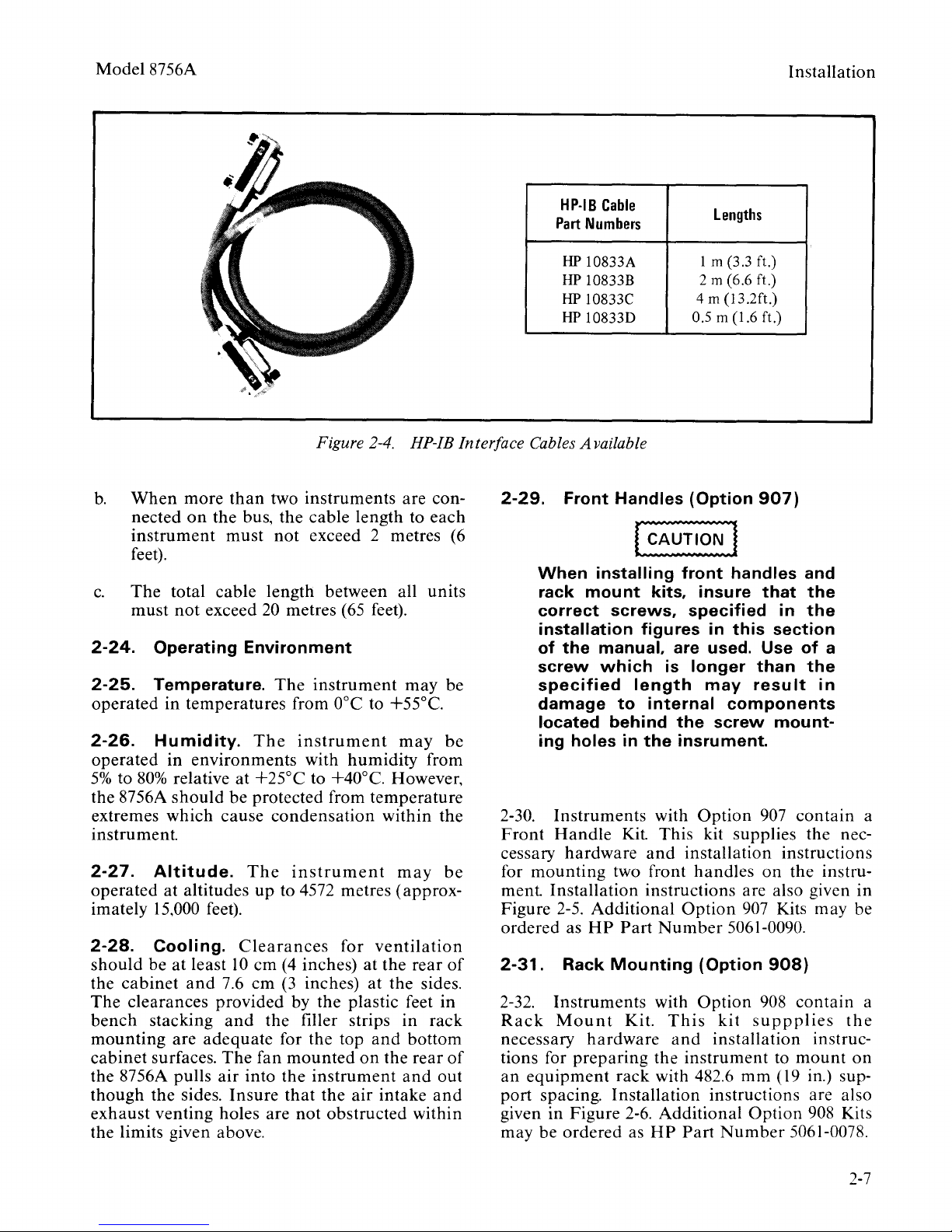
Figure 2-4. HP-IB Interface Cables Available
b.
When
nected
instrument
more
than
two
instruments
on
the bus, the cable length to
must
not
exceed 2 metres
feet).
c.
The
total cable length between all units
must
not
exceed
2-24.
2-25.
operated
2-26.
operated
5%
the 8756A
Operating
Temperature.
in temperatures from
Humidity.
in
to
80%
relative at +25°C to +40°C. However,
should
environments
extremes which cause
20
metres
Environment
The
instrument
The
instrument
with
be
protected from
condensation
(65
feet).
ooc
to +55°C.
humidity
temperature
instrument
2-27.
operated
imately
2-28.
should
the
The
bench
mounting
cabinet
the 8756A pulls
though
exhaust
Altitude.
at altitudes
The
instrument
up
to 4572 metres ( approx-
15,000 feet).
Cooling.
be
cabinet
at
least
and
Clearances
10
em
(4
7.6
em
(3
for
ventilation
inches)
at
inches) at the sides.
clearances provided by the plastic feet in
stacking
are
surfaces.
the sides.
and
adequate
The
fan
air
into the
Insure
the filler strips
for the top
mounted
and
on
instrument
that
the
air
venting holes are not obstructed within
the limits given above.
are con-
may
may
within
may
the
rear
in
bottom
the
rear
and
intake
each
(6
be
be
from
the
be
of
rack
of
out
and
Installation
HP-18
Cable
Part
Numbers
HP
10833A
HP
10833B
HP
10833C
HP
10833D
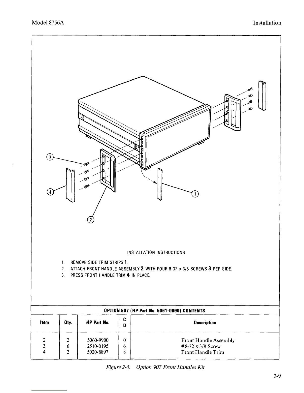
2-29.
2-30.
Front
cessary
for
ment
Figure
ordered as
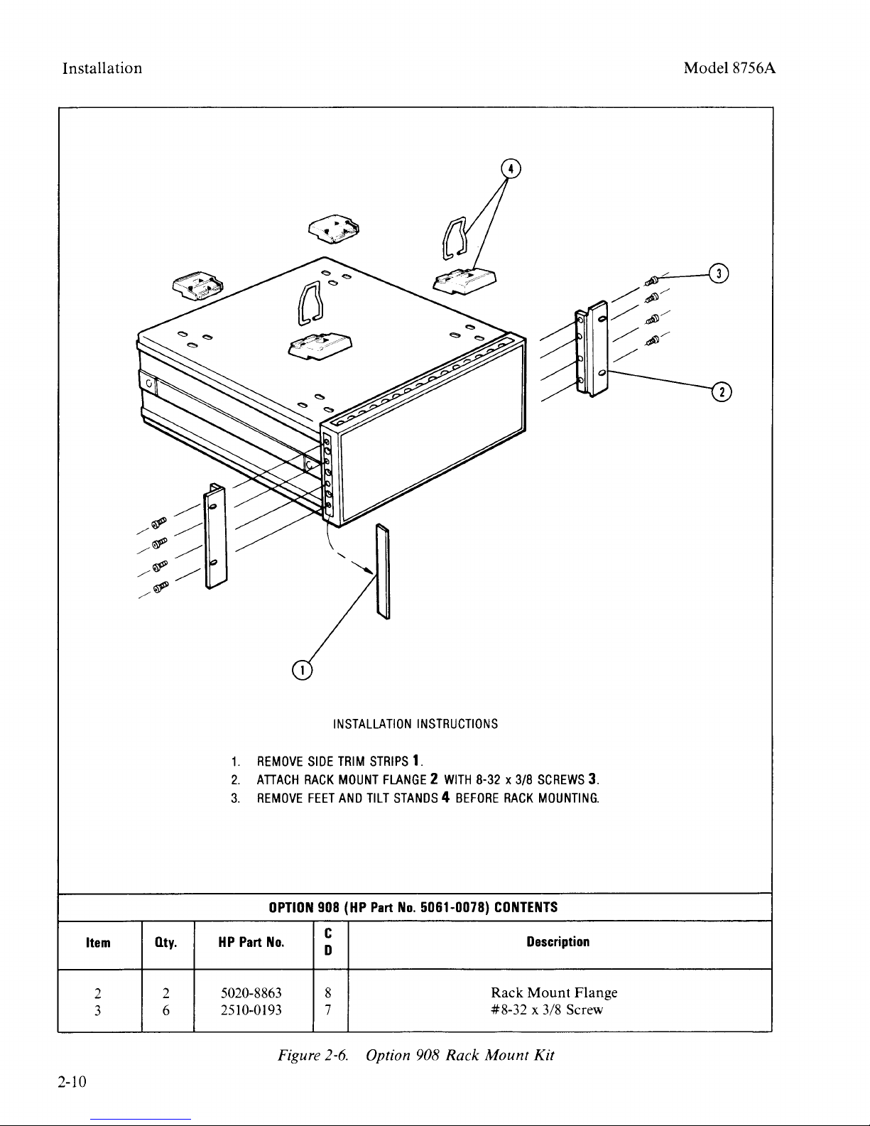
2-31.
2-32.
Rack
necessary
tions for
an
Front
When
rack
correct
installation figures in
of
the
screw
specified
damage
located behind
ing holes in
Handles
installing
mount
screws,
manual, are used. Use
which
length
to
Instruments
Handle
Kit
hardware
mounting
two front
Installation
2-5.
Additional
HP
Part
Rack
Mounting
Instruments
Mount
Kit.
hardware
preparing
equipment
rack
kits, insure
is
internal
the
with
This kit supplies the nec-
and
instructions are also given in
Number
with
the
with 482.6
Lengths
1m
(3.3 ft.)
2m
(6.6 ft.)
4 m (13.2ft.)
0.5 m (1.6 ft.)
(Option
front
specified
longer
may
the
insrument.
Option
907)
handles and
that
in
this
section
than
result
components
screw
mount-
907
contain
the
the
of
the
a
in
installation instructions
handles
Option
on
the instru-
907
Kits may be
5061-0090.
(Option
Option
This
and
kit
installation
instrument
908)
908
suppplies
to
mm
(19 in.) sup-
contain
instruc-
mount
the
on
port spacing. Installation instructions are also
2-6.
given in Figure
may be
ordered
Additional
as
HP
Part
Option
Number
908 Kits
5061-0078.
a
a
2-7
Page 12
Installation
Model8756A
2-33.
(Option
2-34.
Rack
bination
908
hardware
paring
rack with 482.6
with the
instructions
Additional
HP
2-35.
2-36.
2-37.
shipped
Rack
909)
Instruments
Mount
of
the
Kit.
This
and
the
instrument
addition
Option
Part
Number
STORAGE
Environment
The
instrument
in
environments
Mounting
with
Kit with
Option
kit
with
Option
Front
907
Kit
supplies
Front Handles
909
contain
Handles. a com-
and
the
Option
the
necessary
installation instructions for pre-
to
mm ( 19
are
mount
in.)
of
front handles.
also
given
on
equipment
support
Installation
in
Figure
spacing,
909 Kits may be ordered as
5061-0084.
AND
SHIPMENT
may
within
be
the following
stored
2-7.
or
limits:
Temperature
Humidity...
. . . . . .
5%
to
-40oC
95%
to +75oC
relative at
0°
to +40°C
2-38.
Altitude..
(Approximately
The
. . . . . .
instrument
Up
to 15240 metres
50,000 feet)
should
be
protected from
temperature extremes which may cause condensation in the instrument.
2-39.
Packaging
offices. A complete
diagram
kaging materials used for the 8756A is
Figure
a
Hewlettindicating
address,
(located
container
In
by
2-41.
general instructions
2-9.
If
the
instrument
Packard
the type
model
on
FRAGILE
any
correspondence, refer to the
model
number
Other
for servicing,
number,
rear
panel
and
Packaging.
of
to assure careful handling.
should
kaging with commercially available
and
listing
shown
is being
returned
attach
service required,
and
full serial
serial plate).
number
Mark
instrument
full serial number.
The
following
be
used
for repac-
packaging
of
pac-
a tag
return
the
in
to
materials:
a.
Wrap
plastic.
Office
indicating
return
the
instrument
If
shipping
or
Service
the
address.
in heavy
to a Hewlett-
Center,
type
of
model
paper
Packard
attach
a
service required,
number,
and
full
or
tag
serial number.
b.
Use a strong
c.
Use
around
vide a firm
ment
control
d.
Seal
e.
Mark
enough
inside
the
the
shipping
all sides
cushion
the
panel
with cardboard.
shipping
shipping
container.
shock-absorbing
of
the
instrument
and
to prevent move-
container.
container
container
securely.
FRAGILE
material
tp pro-
Protect
the
to
assure careful handling.
2-40.
Original Packaging.
Containers
materials identical to those used in factory packaging are available
through
Hewlett-
2-8
and
Packard
f
In
any
ment
by
number.
correspondence, refer to the instru-
model
number
and
full serial
Page 13
Model8756A
Installation
1.
REMOVE
2.
ATIACH
3.
PRESS
Item
2
3
4
Qty.
2
6
2
SIDE
TRIM
FRONT
HANDLE
FRONT
HANDLE
HP
Part
5060-9900
2510-0195
5020-8897
STRIPS
TRIM 4 IN
OPTION
No.
Figure
INSTALLATION
1.
ASSEMBLY 2 WITH
PLACE.
907
(HP
Part
No.
c
D
0
6
8
2-5.
Option 907 Front Handles Kit
INSTRUCTIONS
FOUR
8-32 x 3/8
5061-0090)
CONTENTS
Front
#8-32
Front
SCREWS 3 PER
Description
Handle
x 3/8 Screw
Handle
Assembly
Trim
SIDE.
2-9
Page 14
Installation
Model8756A
1.
REMOVE
2.
ATIACH
3.
REMOVE
OPTION
Item
2
3
Qty.
2
6
HP
Part
No.
5020-8863
2510-0193
Figure
2-10
INSTALLATION
SIDE
TRIM
RACK
MOUNT
FEET
AND
908
(HP
c
D
8
7
2-6.
INSTRUCTIONS
STRIPS
TILT
1.
FLANGE 2 WITH
STANDS 4 BEFORE
Part
No.
5061-0078)
Option 908
Rack
8-32 x 3/8
RACK
CONTENTS
Rack
#8-32
Mount
SCREWS
MOUNTING.
Description
Mount
Flange
x 3/8 Screw
Kit
3.
Page 15
Model8756A
Installation
1.
Item
2
3
4
REMOVE
2.
ATIACH
SCREWS 4 PER
3.
REMOVE
Qty.
2
2
6
SIDE
TRIM
RACK
MOUNT
SIDE.
FEET
AND
HP
Part
5020-8875
5060-9900
2510-0194
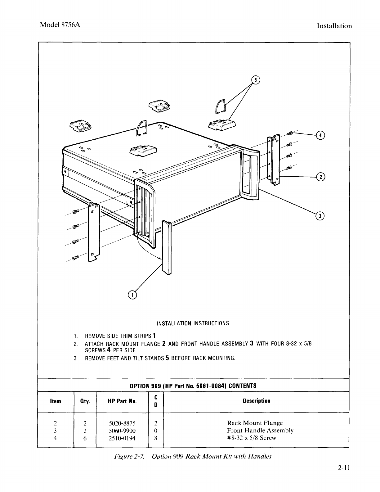
Figure
INSTALLATION
STRIPS
TILT
OPTION
No.
1.
FLANGE 2 AND
STANDS 5 BEFORE
909
c
D
2
0
8
2-7.
Option 909
(HP
FRONT
Part
INSTRUCTIONS
HANDLE
RACK
No.
5061-0084)
ASSEMBLY 3 WITH
MOUNTING.
CONTENTS
Rack
Front
#8-32
Rack
Mount Kit with Handles
Description
Mount
Handle
Flange
Assembly
x 5/8 Screw
FOUR
8-32 x 5/8
2-11
Page 16
Installation
Model8756A
R
1.
EMOVE
RACK
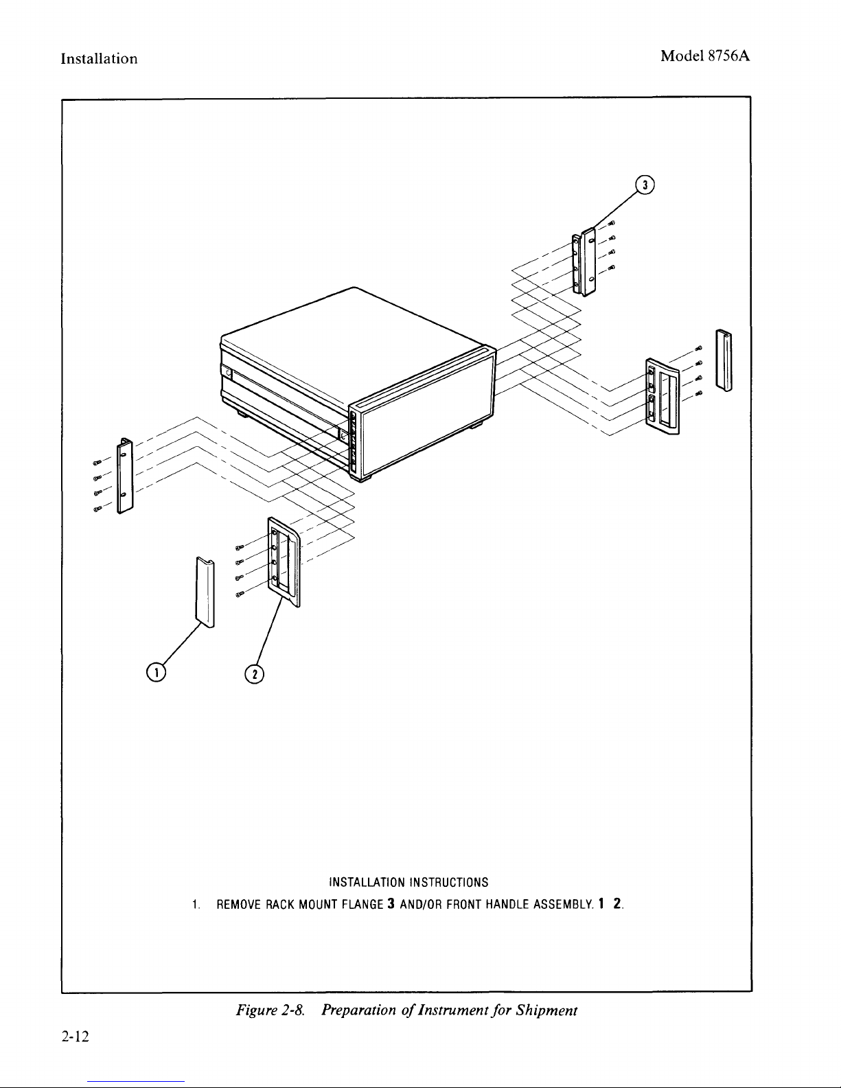
2-12
INSTALLATI
MOUNT
F
LANGE 3 AND/OR
ON
INSTRUCTIONS
nstru Preparation
oifl
FRONT
HAND
mentforSh"
LE
ASSEMBLY.
zpment
1
2.
Page 17
Model8756A
Installation
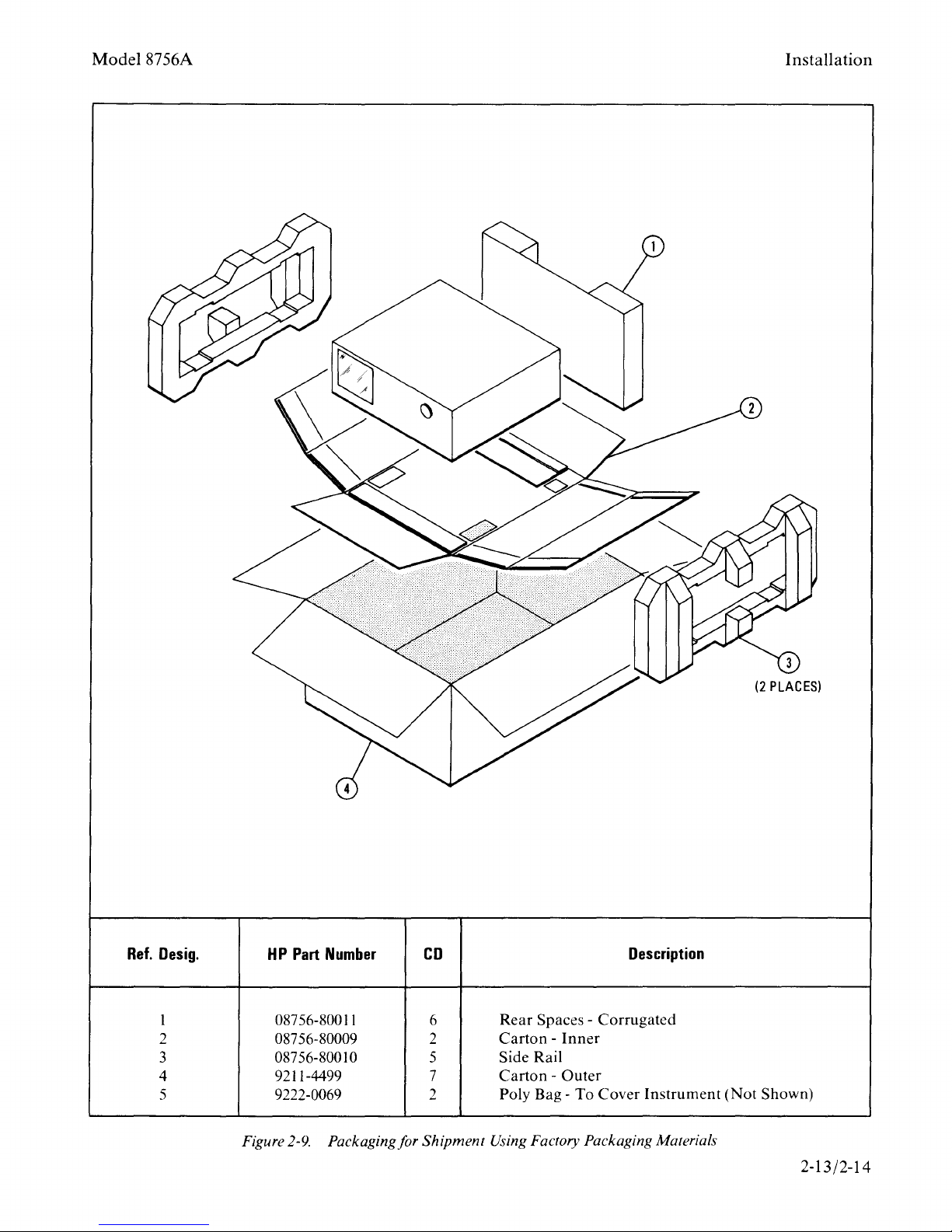
Ref.
Desig.
1
2 08756-80009 2
3
4 9211-4499 7
5 9222-0069 2
HP
087
087
Figure
Part
56-800
56-80010 5
2-9.
Number
11
Packaging for Shipment Using Factory Packaging Materials
CD
6
Rear
SpacesCarton -Inner
Side Rail
Carton -Outer
Poly
Bag-
To
Description
Corrugated
Cover
Instrument
(Not
Shown)
2-13/2-14
Page 18
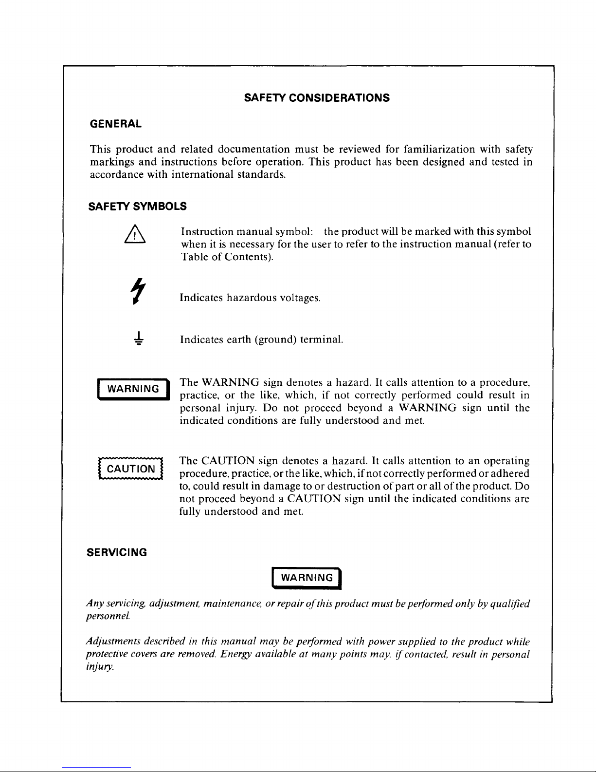
GENERAL
SAFETY CONSIDERATIONS
This product
markings
accordance with international standards.
SAFETY SYMBOLS
WARNING
._
____
and
related documentation must be reviewed for familiarization with safety
and
instructions before operation. This
Instruction
when it
Table
Indicates
Indicates earth (ground) terminal.
1
The
WARNING
_.
practice,
personal injury.
indicated conditions are fully understood
manual
is
necessary for the user to refer to the instruction
of
Contents).
hazardous
or
the like, which,
symbol: the product will be marked with this symbol
sign denotes a hazard.
Do
product
voltages.
if
not correctly performed could result in
not
proceed beyond a
has been designed
It
calls attention to a procedure,
WARNING
and
met.
and
tested in
manual
sign until the
(refer to
The
CAUTION
procedure, practice,
to,
could result in damage to
not proceed beyond a
fully understood
SERVICING
Any
servicing. adjustment. maintenance. or repair
personnel.
Adjustments described in this
protective covers are removed. Energy available at
injury.
manual
sign denotes a hazard.
or
the like, which,
CAUTION
and
met.
I
WARNING
may
be performed with power supplied
or
destruction
I
of
this product
many
points may,
It
calls attention to
if
not
correctly performed
of
part
or
all
sign until the indicated conditions are
must
be performed only by qualified
if
contacted. result
an
operating
or
adhered
of
the product.
to
the product while
in
personal
Do
Page 19
General
Information
Model8756A
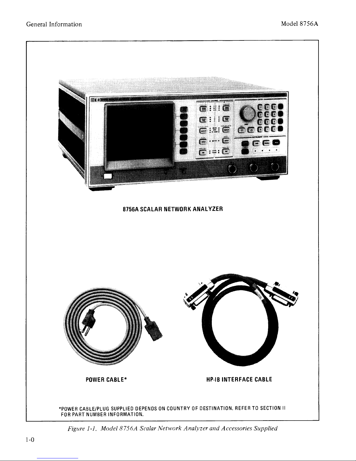
8756A
SCALAR
NETWORK
ANALYZER
*POWER
FOR
PART
Figure 1-1.
POWER
CABLE/PLUG
NUMBER
CABLE*
SUPPLIED
INFORMATION.
Model8756A
1-0
DEPENDS
Scalar
ON
COUNTRY
Network
OF
DESTINATION.
Analyzer
HP-IB
and
INTERFACE
REFER
Accessories
CABLE
TO
SECTION
Supplied
II
Page 20
Model8756A
SECTION I
GENERAL INFORMATION
1-1. INTRODUCTION
1-2.
This
Operating
tains
information
test, adjust,
Model
1-1
plied
tion, description, options, accessories, specifications,
1-3.
which
a.
b.
c.
d.
e.
8756A
shows
This
This
provide
SECTION
includes a brief
ment, safety
supplemental
identification,
sories available,
test
SECTION
information
tion
nectors, storage
SECTION
three
operating
information
operation
Notes
IB
SECTION
contains
instrument
with
SECTION
information
and
and
Scalar
the
instrument
section covers
and
other
manual
information
I,
equipment.
for use,
subsections
which
use
of
the
information
published
align
the
and
Service
required
service
Network
basic
is divided
GENERAL
description
considerations,
characteristics,
options
and
II,
INSTALLATION,
for initial inspection,
rack
and
III,
OPERATION,
information,
(not-HP-IB),
information
provide
87
56A).
IV,
PERFORMANCE
performance
specifications.
V,
ADJUSTMENTS,
required
instrument
to install, operate,
the
and
instrument
information.
as follows:
a list
mounting,
shipment.
which
information
required
to
manual
Hewlett-
Analyzer.
accessories sup-
into
eight sections
INFORMATION,
of
specifications,
available,
of
recommended
contain
local
and
(Programming
is in
properly
after repair.
con-
Packard
Figure
identifica-
the
instru-
instrument
acces-
provides
prepara-
mating
consists
to verify
accordance
con-
general
operation
remote
on
HP-
TESTS,
that
contains
adjust
of
f
SECTION
contains
parts
and
g.
SECTION
CHANGES,
tion to
earlier
h.
SECTION
overall
troubleshooting
Each
covered
contains
diagram,
troubleshooting
proper
1-4.
Supplied
Information
copy
of
the
and
should
by
the
operator.
ing
Information
through
The
1-5.
is
a Microfiche
be
used
cies
to
60
microfiche
Manual
tinent
1-6.
1-7.
Table
mance
instrument
your
part
number
Also listed
to
order
of
the
manual.
photo-duplicates
Changes
Service Notes.
SPECIFICATIONS
Instrument
1-1.
standards
General
VI,
REPLACEABLE
information
assemblies.
VII,
MANUAL
contains
make
this
equipment
VIII, SERVICE,
instrument
assembly within the
on a separate
a circuit description,
component
maintenance
with this
Supplement.
first
three
be
kept with
Additional
Supplement
nearest
is listed
on
the title page
part
4x6-inch microfilm
Each
package
supplement
specifications
These
is
specifications
or
tested.
required
backdating
manual
configurations.
block
and
repair
Service Sheet
location diagram,
information
of
the
manual
The
Supplement
sections
the
instrument
copies
can
Hewlett-
on
the title page.
number.
of
also
limits
Table
This
microfiche
the
manual
includes
as well as all per-
against
1-2
Information
PARTS,
to
order
BACKDATING
informa-
compatible
provides
diagram
procedures.
instrument
schematic
to
aid
instrument.
is
an
Operating
of
this
of
the
be
Packard
of
this
number
transparen-
contains
pages.
the
are
listed
are
the perfor-
which
lists
supplemen-
all
with
an
with
which
and
in
the
is a
manual,
for use
Operat-
ordered
office.
manual
can
up
The
latest
in
the
is
1-1
Page 21

General
Information
Model8756A
tal characteristics.
are
not
specifications
tics
included
Supplemental
as
additional
but
are
user.
1-8.
1-9.
tested in
standards.
related
familiarization
instructions. A
siderations
1-10.
MANUAL
1-11.
ment
serial
digits
SAFETY
This
CONSIDERATIONS
product
accordance
has
been
with
Before operation, this
documentation
with
must
safety
complete
precedes Section I
INSTRUMENTS
SERIAL
PREFIX
,.-'----,
SER
1234A
FACTORY}
INSTALLED
OPTIONS
Figure 1-2. Ty pica! Serial
Attached
is a serial
number
and
letter
OPT
r7,+~
~f.LJ
HEWLETT • PACKARD
to
the
number
is
in
two parts.
are
the serial
001
rear
listing
COVERED
MADE IN
plate
last five digits are the suffix.
same
only
The
and
tents
the
SERIAL
1-12.
printing
ber
unlisted
instrument
this
ment
Changes
for all identical instruments; it
when a change
suffix, however,
is
different for
of
this
manual
serial
number
NUMBERS
An
instrument
of
this
prefix
that
is
serial
is
each
apply
on
manual
not
listed
number
made
is
assigned sequentially
instrument.
prefix(es)
the
manufactured
may
on
prefix
is different from those described in
manual.
is
The
manual
accompanied
supplement.
for this newer instru-
by a
This
supplement
characteristics
typical characteris-
information
for the
manufactured
international
safety
product
be
reviewed for
markings
of
of
NUMBER
SUFFIX
r-""-.
12345
Number
panel
(Figure
number
The
Safety
this
USA
of
The
prefix
Con-
manual.
BY
Plate
the instru-
1-2).
first four
prefix; the
is
changes
to
the
instrument
The
con-
to
instruments
listed
with
under
title page.
after the
have a serial
the title page.
num-
This
indicates
yellow
Manual
contains
and
and
and
The
the
the
'change
the
1-13.
supplement
recting
manual
Hewlett-
information'
manual
In
addition
errors
as
Packard
to the
may
contain
in
current
recommends
that
newer
to
the
and
ically request the latest
plement.
identified with this
number,
title page.
ment
1-14.
number
or
in
your
1-15.
1-16.
Analyzer
is
capable
reflection
RF
cies.
over
and
or
sweep
through
manual
the
connection
the A
and
1-17.
controls
identical
The
step keys,
measurement
Soft Key menus.
allows storage
provides for a
the
The
supplement
manual's
both
of
which
Complimentary
are available from Hewlett-Packard.
For
information
prefix
the
nearest
DESCRIPTION
The
that
Manual
Hewlett-
Model
is
not
Changes
Packard
8756A
is a microprocessor
of
making
and
transmission
(radio
the
can
frequency)
The
8756A
Hewlett-Packard
control a plotter
is
completely
oscillator
the
8756 System Interface. A
measurement
of
detector(s)
B,
orR
detector
the
use
of a compatible
The
CHANNEL
the
operation
Entry
channels,
area
or
keypad.
data,
allows
and
data
channel
The
and
recall
PRESET
status
of
the
instrument
operation.
1-18.
SET] is pressed,
forms
proper
functions.
test, they are
Upon
an
initial
internal
operation.
If
errors
indicated
power
the
8756A
hardware
and
or
failures
explains
how
to
instrument.
change
manual.
Manual
appear
information,
information
To
accurate
that
Changes
for this
print
date
on
the
copies
of
concerning
listed
on
the
supplement,
for cor-
keep
as possible,
you period-
manual
and
manual's
the supple-
a
title page
contact
office.
scalar
Scalar
based
(magnitude
Network
receiver.
measurements
and
microwave frequen-
programmable
Interface Bus (HP-IB),
(HP
(HP
7470A
8350B
or
or
9872C)
8340A)
complete
with
the
inputs
8756A
and/or
on
the
requires
bridge(s) to
front panel,
source.
area
on
the
front
of
two
independent,
three
The
detector inputs.
entry
using
Display
the
shows
information,
Instrument
of
the
of
the
8756A
on,
State
instrument
and
under
or
remote
after [PRE-
automatically
initializes
on
the
check
occur
CRT
to verify
certain
during
Display.
adapt
the
this
sup-
is
part
serial
It
only)
at
panel
but
knob,
the
and
area
state,
shows
per-
this
1-2
Page 22
Model8756A
General
Information
1-19.
1-20.
select
POWER] (A. B, R), [DISPLAY]
Memory,
[SCALE] (20,
sion),
the
PLAY--.MEM],
(which
Reference
CRT
1-21.
1-22.
entered
(knob,
1-23.
1-24.
CRT
above
Scale
Cursor
channel
graticule. Soft Keys
keys to
functions
of
(Averaging
(Short/Open
[PLOT]
7470A
ON/OFF,
(Modulation
1-25.
Five Key Channel Operation
Five
front
[MEAS
or
and
[REF]
[SHIFT] key
scales
Level so
panel
RATIO]
keys for
(NR
Measurement
10,
5,
2,
I,
.5,
(LEVEL
enables
[MKR--.REF],
the
data
that
B/R
minus
.2,
or
POSition).
[CHAN
and
the
Display).
Data Entry
Data
Data
Display.
the
per
for
the
using
step keys,
Digital Display
value.
activated
the
one
or
for
both
The
graticule,
Division,
The
is
immediate
of
keypad).
Channel
annotates
Reference
Reference
shown
various
the
Entry
channels
on
may
be
right
of
functions
Annotation
the
Position
the
enabled
the
include: [CURSOR]
the
cursor
(outputs
or
Instrument State and SAVE/RECALL
for
both
channels),
Factor,
Averaging
calibration
the
current
ON/OFF),
and
display
9872C Plotter), [DISPLAY]
Hold,
Menu
ON/OFF,
OFF),
Service).
each
channel
NB),
[MEAS
(Measurement,
Memory),
or
.1
dB
per
Use
OFF], [DIS-
and
[AUTO]
changes
data
fits
on
may
area
functions
is
shown
on
Measurement,
Level value,
for
left
side
using
display.
(reads
[AVERAGE]
Detector
the
Offset),
to
an
These
[CAL]
(Labels
and
[MORE]
divi-
the
the
be
the
area,
and
each
of
the
the
value
HP
of
drift-free
is
square-wave
vides
reflection.
detected
to
an
shaping,
1-29.
kHz
the
rear
drive
(8340A)
drive
source
1-30.
1-31.
1-32.
contains
necessary
operation.
the
source
or
and
8756A
the
The
modulation
modulation
three
Modulator
panel
the
of
an
of
external
the
external
without
OPTIONS
Option
Option
a
hardware
modulated
for
transmission
the
modulation
detector
data
the
RF
internal
907,
907
pair
the 8756A. Refer to
and
Service
this kit
1-33.
1-34.
contains a pair
hardware
rack
with 482.6
ing. Refer to
Service
this
kit
1-35.
Kit
dles
Manual
and
instructions
Option
Option
to
Manual
and
instructions
Option
908,
908
of
mount
mm ( 19
Section
909,
An
RF
or
microwave
at
27.8 kHz.
the
8756A.
Absolute
signals
envelope
input. After filtering
is digitized
drive
is
available
Drives
8756A.
AM
or
microwave
modulator
and
needed
BNC
They
or
from
may
PULSE
as
modulation
Front Handles Kit
(HP
Part
Number
of
front
for
Section
for a
Rack
(HP
flanges
the
II
for a
handles
mounting
II
of
detailed
for
installation.
Mount
Part
Number
and
8756A
in
inches)
of
this
detailed
horizontal
Operating
for installation.
Rack
Mount/Front
signal
and
power.
are
is
carried
displayed.
for
the
any
one
outputs
be
on
used
INPUT
source,
required
or
for a
capability.
5061-0090)
and
the
handles
this
Operating
description
Kit
5061-0078)
the
necessary
an
equipment
spac-
description
Han-
pro-
then
and
27.8
of
the
to
to
the
to
of
and
of
1-26.
tion
Diodes).
pressing
a
to a
used
The
is
identified
Local
[LOCAL]. [PRESET] is
hardware
predefined
to
save/recall
Instrument
by 4 LED's
operation
self-test
and
state. [SAVE]
State for
may
restores
up
to
states.
1-27.
1-28.
que
technique
AC
Modulation
The
8756A uses
in
conjunction
has
the
advantage
with
the
its
AC
detector
remote
(Light
be
used
the
and
[RECALL]
nine
detection
of
providing
opera-
Emitting
restored
to
perform
instrument
front
panel
techni-
inputs.
This
nearly
by
are
1-24.
Option
contains
one
Option
in
tions
II
of
this
detailed
for
installation.
1-36.
Service
1-37.
one
an
The
Operating
Operating
909
one
Option
908
preceding
Operating
description
Option
Manual
standard
and
Information
(HP
Part
907
Front
Rack
Mount
paragraphs).
and
Service
of
this
910,
Extra
instrument
Service
Number
5061-0084)
Handles
Kit (see descrip-
Refer to
Manual
kit
and
instructions
Operating
is
supplied
Manual
(including
supplement).
Kit
and
Section
for a
and
with
Each
1-3
Page 23
General
Information
Model8756A
Option
and
obtain
Manuals
part
cover
1-38.
1-39.
work
The
country
manual
1-40.
SUPPLIED
1-41.
modulation
use
three detectors
required
the
910 provides
Service
Manual
one
additiona 1 Operating
after initial
number.
of
ACCESSORIES SUPPLIED
Figure
this
listed
manual.
1-1
Analyzer
power cable
of
destination. Refer to Section II
for
HP
EQUIPMENT
shipment,
on
shows the 8756A
HP-
IB
supplied
Part
Number
A swept microwave source with
capability,
of
an
to
8756A
external
make
Refer to
modulator)
and/
or
microwave
EQUIPMENT
for specific examples.
EQUIPMENT
1-42.
1-43.
may
detects
RF
11664AIB
Up
be
the
signal.
diode to achieve
quency
to
11664B
1-44.
tional Bridges
1-45.
18
G Hz.
The
range
Detector
85020AIB
Directional
8755C
bridge,
Scalar
one
AVAILABLE
Detectors
to three
used with
envelope
Each
Model
the
of
detector uses a
-50
of
the 11664A
The
extended
is
10
MHz
or
85020A/B
Bridges designed for
Network
zero-bias Schottky
measures the return loss
measurements
splitter
B).
4.3
The
GHz
The
(HP
The
85020A
GHz.
85020B
with a
85021NB
range, with
may
be
11667A)
has
a frequency
with a
nominal
has
a frequency range
nominal
provides
the
85021A (APC-7 test
and
additional
(and
suppliment).
order
the title page
Operating
and
by
and
Service
manual
Scalar
cable
and
power cable.
depends
upon
of
information.
REQUIRED BUT
NOT
27.8
(internal
or
and
through
from
one
directional bridges are
measurements
AVAILABLE
11664NB
8756A.
the 27.8
dBm
sensitivity.
Detector
frequency
to
26.5
85021
and
85021A/B/C
Analyzers.
of
the
test device.
made
by
detector
impedance
impedance
an
extended
kHz
biased
AlBIC
adding
range
The
modulated
is
range
GHz.
the
8756A
Within
diode
(HP
of
of
0.01
of
75
frequency
port
Detectors
11664NB
Schottky
The
10
MHz
of
Direc-
each
detector
Ratio
a power
11664N
of
0.0 I to
50
ohms.
to 2.4
ohms.
connec-
To
rear
Net-
the
this
kHz
the
to
with
fre-
the
are
and
tor)
and
the
85021 C (Precision
connector)
covering
85021 B (APC-3.5 test
0.01
to
26.5
GHz.
impedance
1-46.
1-47.
RF
signal
capability
kHz
rate.
signals from
kHz
from
Operation
information
regarding
1-48.
1-49.
to
18
device
With
Detector, two
of
insertion
to
the
manual
and
measurements
is 50 ohms.
11665B
The
11665B
source
of
modulating
The
11665B
15
the
portion
on
the
use
11
666A
Reflection
GHz
the
using
addition
may
the
simultaneous
and
Section III
for
further
Modulator
Modulator
MHz
8756A. Refer to the Section III
of
test setup
of
Reflectometer Bridge
measurements
be
11666A Reflectometer Bridge.
return
0.01
port
85021A/B/C
used
the
Modulator
to
this
the
11665B
made
of
an
loss
Operation
information
regarding
Type
to
18
GHz.
connector) covering
is
required
does
RF
not
output
modulates
18
GHz
with
manual
and
measurements
Modulator.
from 40
with
one
external
ratio
measurements
may
be
made. Refer
portion
on
the
11666A Reflectometer Bridge.
1-50.
1-51.
mended
transmission
This
output
source leveling
tions.
over a frequency
wideband
minimum
1-52.
1-53.
five low pass filters with
quencies: 11688A
11684A. 6.8
11686A
recommended
generated
cise
11667
The
A Power Splitter
11667A
when
Power
making
measurements
Splitter
low
with
loss
two-resistor type splitter provides excellent
SWR
at
the
The
0.25 dB
measurements
of
uncertainty.
11678A
The
11678A Low Pass
13.0
GHz.
by
broadband
auxiliary
or
ratio
tracking
range
Low
Pass
2.8
GHz:
GHz:
11685A, 9.56
The
to reduce
the
RF
source
measurements.
arm
when
measurement
between
of
de to
to
18
be
Filter Kit
Filter
the
following
11689A 4.4
use
of
low
undesirable
when
output
GHz
made
Kit
pass
making
N test
and
port
the
nominal
if
the
have
at
the
a 27.8
test
the
27.8
for
further
MHz
coupling
11664NB
of
this
test setup
use
of
the
is recom-
wideband
the
8756A
used
for
applica-
arms
allows
with a
contains
cutoff
fre-
GHz:
GHz:and
filters
harmonics
pre-
is
1-4
Page 24

Model8756A
General
Information
1-54.
1-55.
11668A
The
11668A
recommended
active devices
Use
of
the
11668A
the
11665B
drive
feedthrough
possible
vents
1-56.
1-57.
Cable
Cable
tor
or
Scalar
operation
mance
1-58.
1-59.
use
of
After
specific
Modulator,
11679AIB
The
11679A 7.6 m (25 foot)
and
the
fit directly
11666A
Network
is
degradation.
11664C
The
11664C
standard
initial
diode
interchangeable
Frequency
upper
extending
1-60.
1-61.
the
8620C,
families
sources
the
8340A,
stop/marker
range
end
the
Sweep
The
8340A
may
for
the
the
by
and
frequencies
display: Save
sweeper
the
Enable
Sweep two
and
Sweep).
8340A
the
Drive
Drive
panel
ulator
Sweep
ULATION
simultaneously
sweeper
modulation:
different
display
The
Synthesized
RF
output
output.
is
connected
EXT
AM
Drive
Oscillator
INPUT.
High
Pass
High
Pass
when
which
making
have
High
Pass
reduces
from
8m
amplifier
11679B
saturation.
Extension Cables
61
m (200 foot)
between
Reflectometer
Analyzer.
thus
permitted
Detector
Detector
diode
detector
detector
the
operating
Oscillators
detectors with
with
the
of
the
11664C is
diode
calibration
used,
range
Synthesized
8350A/B
be
used
as swept
8756A.
8756A
With
is
able
and
and
recall
front-panel
with
simultaneously
Set
the
frequency
both
simultaneously
8620C Sweep
Sweep
signal with
With
to
input.
is
connected
front
the
the
With
the
8620C
Sweep
panel
The
Filter
Filter
accessory
measurements
gain
below
Filter,
V to I m V
placed
the
modulator
50
and
Extension
Extension
the
11664NB
Bridge
and
Remote
without
Adaptor
Adaptor
allows
the
with
the
11664C is
11664NB
detectors.
limited
detector
of
the
used,
8756A.
Sweep Oscillator,
Sweep
either
Oscillator
or
CW
the
8350B
to:Interrogate
annotate
the
states
the
8756A:
with
the
proper
sweep time:
or
power
(Alternate
Oscillator
Oscillator
8756A
Modulator
the
Modulator
modulate
Oscillator
the
to
8340A,
the
the
Synthesized
PULSE
8350A/B
on
MHz.
after
pre-
Detec-
8756A
detector
perfor-
the
8756A.
the
on
the
thus
signal
or
start/
CRT
of
the
Preset
8756A:
ranges
and
the
rear
Mod-
MOD-
Sweep
is
Oscillator
the
RF
source
1-62.
l-63.
duced
7470A
Plotters
Hard
by
or
segmented
and
annotation:
trace:
1-64.
1-65.
ber
8756A.
•
Plot
Service Accessories
A Service Accessory Kit
08756-60020) is
The
One
(HP
provided
Amplifier
•
One
extender
This
shooting
Two
test
points
troubleshooting
pulser,
•
One
1400-0734)
(HP
as
an
when
•
One
(HP
for
ease
blies.
extractors.
1-66.
1-67.
8756A
may
critical
RECOMMENDED
Equipment
is
be
substituted
specification
is
capable
at
copy
the
8756A
9872C
into:
of
27.8 kHz.
plots
when
digital
Graticule
Channel
all.
available
accessory
15-pin
Part
Number
for
kit
printed
use
in
Assemblies
special
board
+5V
(HP
is
the
test
are
purpose
Part
provided
A3
points
provided
devices (logic
current
16-pin I.C.
Part
aid
tracer).
Test
and
one
Number
for
probing
troubleshooting.
Log
Amplifier
Part
Number
in
removing
which
do
not
required
listed in
Table
if
listed
internally
are
automatically
used
with
plotter.
lines
Plots
only:
1 trace:
(HP
for
servicing
includes:
circuit
5060-0049).
hoard
This
troubleshooting
(A7,
AS,
A9).
printed
Number
through
and
for
Clip
20-pin
1400-0979)
circuit
08756-60015).
to
aid
A6
two digital
powering
(HP
Part
I.C.
are
Integrated
Assembly
03950-4001).
Log
Amplifier
have
board-mounted
TEST
1-3.
it meets
in
EQUIPMENT
to
maintain
Other
or
exceeds
the
table.
modulating
pro-
an
HP
may
be
Labeling
Channel
Part
Num-
the
extender
board
the
Log
board
in
trouble-
Assemblies.
ground
digital
probe,
logic
Number
Test
Clip
provided
Circuits
Extractor
Provided
Assem-
the
equipment
the
2
is
1-5
Page 25
General
Information
Model8756A
1-68.
BUS.
1-69.
remote
HEWLETT-PACKARD INTERFACE
( HP-IB)
The
8756A
programming
Hewlett-Packard
provides a remote
trol
of
the
instrument
internal
operator.
tem
etc.)
receives
Several
ting data.
tests) available to the
Remote
controller
that
sends
data
output
commands
from
modes
Through
is
factory
equipped
interface
using
Interface Bus (HP-IB).
operator
with
the
same
(except the line switch
manual
control
(desktop
a subset
the
is
maintained
computer.
or
8756A
are
available
of
computer,
instructions
using
the HP-lB.
for output-
HP-GL
with a
the
This
con-
and
(local)
by a sys-
to
and
(Hewlett-
Packard
may
be
Graphics
plotted
on
Hewlett-Packard's
Standard
tion
entitled
Packard
488-1978. A
of
the
HP-
"Condensed
Interface
IB is
59401-90030).
1-70.
1-71.
face.
to
patable
8756
The
This
control
digital plotter
System Interface
8756A also
is a
port
and
extract
Language).
the
8756A CRT.
implementation
complete
general
provided
Description
Bus"
used
(HP
has
an
8756 System Inter-
exclusively by
information
and/or
sweep oscillator.
user
graphics
The
HP-IB
of
the
descrip-
in the
to
Part
the
Hewlett-
Number
manual
the
from a com-
is
IEEE
8756A
1-6
Page 26
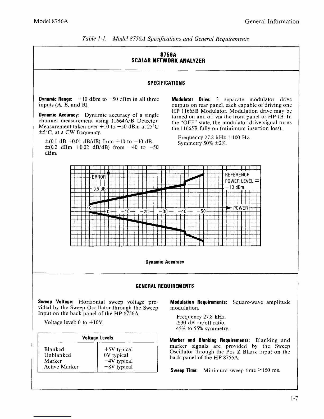
Model 8756A
Table
1-1.
Model8756A Specifications
SCALAR
SPECIFICATIONS
8756A
NETWORK
and
General Requirements
ANALYZER
General
Information
Dynamic
inputs
Dynamic
channel
Measurement
±5°C,
Range:
(A,
Accuracy:
B,
+
and
measurement
taken
at a
CW
frequency.
10
dBm
R).
Dynamic
using
over
±(0.1 dB +0.01 dB/dB) from
±(0.2
dBm
+0.02 dB/dB) from
dBm.
ERROR
0.5
10
to
+I
T
TT
dB
-50
dBm
accuracy
ll664NB
0 to
-50
+10
0
in all three
of
Detector.
dBm
to
-40
-40
101-
a single
at 25°C
dB.
to
-50
20
Modulator
outputs
HP
turned
the
the
301-
Drive:
on
rear
ll665B
on
and
"OFF"
ll665B
state,
fully
Frequency
Symmetry
L...
40
I
Pill
,..
3
panel, each
Modulator.
off
via the front
the
modulator
on
(minimum
27.8
kHz
50%
±2%.
50
separate
capable
Modulation
panel
insertion loss).
±100Hz.
I
REFERENCE
POWER
LEVEL=
+10
dBm
I
I
I I
POWER
modulator
of
driving
drive
may
or
HP-
drive signal
drive
one
be
lB.
turns
In
Sweep
vided
Input
Voltage:
by the Sweep
on
the
back
Voltage level:
Blanked
Unblanked
Marker
Active
Marker
Horizontal
Oscillator
panel
of
0 to +
10V.
Voltage
the
Levels
+5V
OV
-4V
-8V
Dynamic
GENERAL
sweep voltage pro-
through
HP
the
8756A
Sweep
typical
typical
typical
typical
Accuracy
REQUIREMENTS
Modulation
modulation.
Frequency
2:30 dB
45%
to
Marker
marker
and
signals
Oscillator
back
panel
Sweep
Time:
Requirements:
27.8 kHz.
on/off
55%
ratio.
symmetry.
Blanking
are
through
of
the
the
HP
Minimum
Square-wave
Requirements:
provided
Blanking
by
Pas Z Blank
8756A
sweep time 2:150 ms.
amplitude
the
input
and
Sweep
on
the
1-7
Page 27
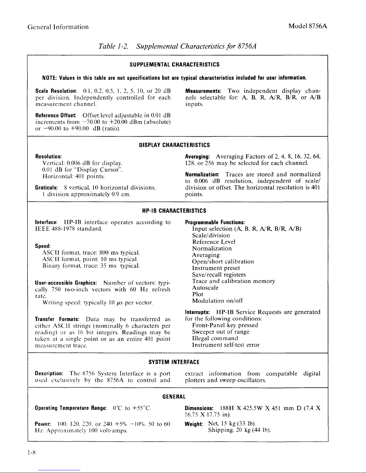
General
Information Model 8756A
Table
NOTE:
Values
Scale
Resolution:
per
division.
measurement
Reference
increments
or
-90.00
Resolution:
Vertical: 0.006 dB for display.
0.01
dB for
Horizontal:
Graticule:
division
I
in
this
table
0.1, 0.2. 0.5, I,
Independently
channel.
Offset:
from
Offset level
-70.00
to +20.00
to +90.00 dB (ratio).
"Display
401
8 vertical,
Cursor".
points.
10
horizontal
approximately
1-2.
are
not
2,
controlled
adjustable
0.9 em.
Supplemental Characteristics for 8756A
SUPPLEMENTAL
specifications
5, I 0.
or
for
in
0.01
dBm
(absolute)
DISPLAY
divisions.
HP-18
CHARACTERISTICS
but
are
typical
20
dB
each
Measurements:
nels
inputs.
dB
CHARACTERISTICS
Averaging:
128.
or
Normalization:
to 0.006
division
points.
CHARACTERISTICS
characteristics
Two
selectable
for: A
Averaging
256
may
be
Traces
dB
resolution,
or
offset
The
included
independent
B, R NR
Factors
selected
are
horizontal
for
user
information.
display
B/R
of
2,
4,
for
each
channel.
stored
and
independent
resolution
chan-
or
NB
8,
16,
32, 64,
normalized
of
scale/
is
401
Interface:
IEEE
Speed:
ASCI I
ASCII
Binary
User-accessible
cally
HP-
488-1978
format
format
format
750
two-inch
rate.
Writing
Transfer
either
reading)
taken
speed: typically
Formats:
ASCII
or
as
at
a single
measurement
Description:
used
exclusively by
The
IB
interface
standard.
trace: 800
point:
trace:
Graphics:
vectors with 60
Data
strings
(nominally 6 characters
16
hit
point
trace.
8756 System
operates
ms
10
ms
35
ms
Number
10
may
integers.
or
as
the
8756A to
typical.
typical.
typical.
of
p.,s
per
be
transferred
Readings
an
entire
Interface
according
vectors: typi-
Hz
refresh
vector.
per
may
be
401
point
SYSTEM
is a
port
control
and
to
as
INTERFACE
Programmable
Input
selection
Scale/
division
Reference
Normalization
Averaging
Open/short
Instrument
Save/recall
Trace
and
Autoscale
Plot
Modulation
Interrupts:
for
the
HP-
following
Front-Panel
Sweeper
Illegal
out
command
Instrument
extract
plotters
information
and
Functions:
(A
B, R NR
Level
calibration
preset
registers
calibration
memory
on/off
IB Service
Requests
conditions:
key
pressed
of
range
self-test
error
from
sweep oscillators.
B/R
NB)
are
compatable
generated
digital
Operating
Power:
Hz.
Temperature
100. 120.
Approximately
Range:
220.
or
240 +5%
100 volt-amps.
0°C to
1-R
+55°C.
-10%.
GENERAL
50 to 60
Dimensions:
188H X 425.5W X
!6.75 X 17.75 in).
Weight:
Net
15
Shipping.
kg (33 lb).
20 kg (44 lb).
451
mm
D (7.4 X
Page 28

Model8756A
Table
1-3.
Recommended Test Equipment
(1
of
2)
General
Information
Instrument
Sweep Oscillator
RF
Plug-in
Detector
12
dB Step Attenuator
120
dB Step Attenuator
Critical
-
10V
0
SWEEP
Specifications
OUT
Ramp
Positive Z-Axis Blanking
IB
HP-
Programmable
Compatible with Sweep Oscillator
70
Internal
Frequency Range: Includes
dB Step Attenuator
50
MHz
Leveled Power Output:
~
13
No
Substitute
dBm at
50
MHz
1 dB Steps
Type N
Calibration
(f) Connectors
Data
at
50
MHz
to
0.01
Resolution
10
dB Steps
Type N
Calibration
(f) Connectors
Data
at 50
MHz
to
O.ot
Resolution
dB
dB
Recommended
HP
8350B
(HP
8350A)
HP
83525A
Opt002
HP
ll664A
(HP
11664B)
HP
355C
OptOOl
OptJ14
HP
355D
OptOOl
Opt
H88
Model
Use*
P,
A,
P,
A,
P,A,
P,A,
P,A,
T
T
T
T
T
Oscilloscope
Oscilloscope Probes
Universal
Counter
Digital Voltmeter
Power Meter
Power Sensor
Signature Multimeter
Logic Probe
Dual
Channel
Bandwidth:
10:1
Divider
Frequency Range:
Frequency Resolution:
Time Internal Resolution:
Accuracy:
Resolution:
Input
HP-
IB
Frequency Range: Includes
Sensitivity:
(HP
~100
MHz
(3
required)
~30
~0.03%
~5
m V
Impedance
(DC):
Programmable
~-55
dBm
ll708A
50
MHz
kHz
~1
Hz
~100
~10
50
Reference
Attenuator Included)
Compatible with
Power Meter
Signature Analyzer
~10
Clock Frequency:
MHz
TTL Compatible
Data
Rate:
~16
MHz
Compatible with Logic Pulser
M.O
MHz
ms
HP
1740A
10
10041A
HP
5316A
HP
3456A
(HP
3455A)
HP436A
HP
8484A
HP
5005NB
HP
545A
(HP
l0525T)
P,
P,
A,T
A,T
P,
T
A,
T
T
T
T
T
1-9
Page 29

General
Information
Table
1-3.
Recommended Test Equipment(2 of2)
Mode18756A
Instrument
Logic Pulser
Current
Service Kit
Modulator
Controller
Printer/Plotter ROM
Advanced
ROM
Tracer
(Equipment
Programming
Critical
TIL
Compatible
TIL
Compatible
Compatible
No
Substitute
below required for
On/Off
Modulation
Personal
(No
Compatible
Compatible
Ratio:
Computer
Substitute)
Specifications
with Logic
Calibration
2::
Rate: 27.778
with Controller
with
Pulser
30
dB at
50
kHz
Controller
Constants
MHz
Recommended
HP
(HP
HP
HP
Adjustment
HP
HP85F
HP P /N
HP
Model
546A T
10526T)
547A T
Use*
PIN 087 56-60020 T
Procedure only)
ll665B
00085-15002
PIN 00085-15005
A,T
A,T
A,T
A,T
16K Memory Module
"CAL56A"
Adapter
Adapter
Band
Pass
Program
Filter
Tape
Compatible with Controller
No
Substitute
N(f) to N(F)
N(m) to N(m)
CF
=50
MHz, BW =
Rejection
SWR~1.2
>20
>20
dB at
dB at
20
100
10
MHz
MHz
MHz
HP
82903A
HP
PIN 08756-10001
HP
P/N
1250-1472
HP
P/N
1250-1475
Te1onic
P/N
50-10-2-EF
A,T
A,T
A,T
A,T
A,T
1-10
Page 30

Model
The
8756A
Operation
section
of
this
manual
SECTION Ill
OPERATION
consists
of
the
following subsections:
Operation
1. OPERATING INFORMATION: A
ing
the
Model
2. OPERATING NOTES:
8756A with
3.
PROGRAMMING
Model
8756A with
8756A
other
Provide
instruments.
NOTES:
other
instruments
tutorial
Provide
complete
information
tutorial
and
controllers.
(Local
information
and
on
Remote) reference
Locally
on
operating
Remotely
operating
on
the
operat-
Model
the
3-i
Page 31

8756A
SCALAR
NETWORK
ANALYZER
©
Copyright
1400
FOUNTAIN
HEWLETT-PACKARD
GROVE PARKWAY.
COMPANY
SANTA
ROSA,
CA
1983
95404
U.S.A.
Printed:
rfin-
APRIL
HEWLETT
~~PACKARD
1983
Page 32

Model
8756A
Operating
Information
3-1.
3-2.
for
Network
8756A
the
SCALAR
INTRODUCTION
This
the
subsection
correct
Analyzer.
with
the
Operating
NETWORK
set-up
Model
Note
ANALYZER
#8756A/8350B/0000-99,
additional
Packard
Programming
3-3.
3-4.
OPERATING CHARACTERISTICS
The
cessor
{magnitude
{radio
is
programmable
Whether
it
can
control
through
instrument
directional
front
panel,
information
Interface
Notes,
Model
based
receiver.
only)
frequency)
or
not
the
8756
requires
bridge{s)
and
8756A
over
the
a
OPERATING INFORMATION
provides
For
8350B
BASIC
which
on
Bus
{HP-IB),
also
Scalar
reflection
and
microwave
the
Model
specific
SYSTEM
the
to
the
use
SECTION
III
complete
and
operation
specific
Sweep
NETWORK
AND
8350B
information
Oscillator,
MEASUREMENTS
SWEEP
follows
using
the
please
included
in
Network
It
is
capable
and
transmission
frequencies.
Hewlett-Packard
8756A
plotter
is
being
and/or
INTERFACE. A
connection
the
A,
B,
of
a
compatible
information
of
the
OSCILLATOR,
this
8756A
refer
this
Analyzer
of
controlled
measurement
of
detector{s)
or
R
detector
Model
on
8756A
operating
please
USING
manual.
over
to
For
the
the
section.
is
a
micropro-
making
scalar
measurements
The
Model
Interface
over
sweep
oscillator
with
and/or
inputs
RF/microwave
necessary
Scalar
refer
8756A
Hewlett-
8756A
8756A
Bus
{HP-IB).
HP-IB,
the
on
source.
the
to
at
RF
the
3-5.
with
measurements
ence.
27.8
device.
detector,
the
modulation
Drive
input
for
3-6.
internal
most
compatible
86230B,
plug-ins
the
The
8756A
its
detectors.
An
RF
kHz
square
When a
the
response.
BNC
outputs.
of
the
a
source
The
8350B
square
86200
86241A,
require
8756A.)
even
or
8756A
drive
RF
without
series
with
uses
microwave
wave,
signal
The
or
Sweep
wave
this
86242A, 86250A,
the
This
with
providing
filters,
8756A
from
any
They
microwave
internal
Oscillator
modulation.
plug-ins
internal
an
external
AC
detection
technique
temperature
signal
is
then
shapes,
provides
one
of
may
be
source
amplitude
with
modulation.
modulator
provides
variations
is
amplitude
the
stimulus
detected
the
three
used
or
provides
All
the
ll869A
86250B,
technique
very
modulated
to
by a compatible
digitizes,
necessary
rear
to
an
drive
external
panel
the
modulation
the
27.8
83500
series
Adapter
{The
86260A,
for
compatibility
in
conjunction
stable
and
RF
the
and
27.8
Modulator
external
kHz
Models
86260B,
interfer-
with
test
displays
kHz
modulator
capability.
with
plug-ins
are
86220A,
86260C
with
a
AM
its
and
3-1
Page 33

Operating
Information
Model
8756A
3-7.
3-8.
OPERATING INSTRUCTIONS
The
*
*
*
*
*
3-9.
3-10.
8756A
all
for
verification
3-11.
OPERATOR'S
The
is
specifications
daily
ERROR
following
FRONT
SOFT KEYS:
REAR
HP-IB:
CRT
functioning
PANEL:
PANEL:
Fig.
GRAPHICS:
CHECKS
Operator's
instrument
after
MESSAGES
describe
Fig.
Fig.
to
repair
3-2
Fig.
3-4.
Fig.
Checks
correctly.
their
verification,
the
3-l.
and
3-3.
3-5.
(see
limits,
or
replacement
operation
Appendix
Fig.
It
3-6)
does
but
incoming
not
is
of
of
A.
verify
an
the
8756A:
that
thoroughly
appropriate
inspection,
digital
the
check
test
or
circuits.
3-12.
CRT
display
For
more
Service.
Error
information
Messages
when
conditions
are
on
shown
these
in
indicate
messages,
the
ACTIVE
a
problem
refer
ENTRY
with
to
Section
AREA
the
of
the
8756A.
VIII
3-2
Page 34

Model
8756A
Operating
Information
FRONT
L-~--"
, G I
I I
I I
F:
I :
I I
I
.....
-----------
I E
L-.!1--~
D I C
PANEL
.. 1
OPERATING
FEATURES
1.
CRT
data
2.
CHANNEL
reference
3.
ENTRY
by
4.
INSTRUMENT
allows
5.
DETECTOR
detectors
6.
SOFT
7.
CRT
8.
LINE
Display
traces,
determines
provides
means
inputs
KEYS
DISPLAY
controls
of
and
line
of
the
STATE
INPUTS
and/or
provide
measurement
other
the
functions.
Data
Entry
Knob,
provides
to
alter
allow
bridges.
additional
measurement,
the
connection
annotation,
information.
for
the
STEP
keys,
information
the
state.
functions
SCALE,
of
CONTROLS.
AC
power
Figure 3-1. Front Panel Operating Features
to
the
8756A.
soft
key
display,
REF,
or
the
Keypad.
on
the
8756A
compatible
for
the
1 = ON, 0 =
(1
of
11)
labels,
scale,
and
soft
instrument
8756A.
OFF.
and
keys
and
3-3
Page 35

Operating
Information
Model
7
8756A
1.
CRT
Display.
several
A
and
information
B
F: D
1--
t/
The
display
MODE
ment,
Active
division,
displayed.
in
Channel
intensity.
L-~--l
, G I
I I
I I
I I
I I
I I
-----------
I E JL.
sections,
LABELS.
the
Marker)
area
A;
is
L_!
for
the
described
The
CURSOR
amplitude,
and
the
The
Channel
shown
__
.. 1
8756A
ratio
(or
reference
Channel
with
~
IC
\
Model
2
below.
or
in
area
higher
is
divided
power
8350B/8340A
the
scale
level
1
LABEL
B.
display
into
measure-
per
value
is
shown
The
Active
are
c
D
MEASurement
~
SCALE
per
SOFT
soft
particular
pressing
soft
DATA
displayed
CHANNEL
CHl~
10.0
A
dB/
I
division
KEY
key
key
DISPLAY AREA.
CURSOR
-28.50,dB
REF
REFerence
LABELS.
selections
menu
the
soft
label.
depending
functions
or
/
0.~0
The
are
or
function
key
The
on
selected.
MARKER
dB
LEVEL
menu
annotated.
to
the
data
the
value
value
of
is
right
trace(s)
soft
available
chosen
of
key
A
by
the
are
or
Figure 3-1. Front Panel Operating Features
3-4
(2
of
11)
Page 36

Model
8756A
Operating
Information
E
F
G
FREQUENCY
Active
Stop
Marker
Frequencies,
frequencies
are
annotated
Oscillator
IB
is
connected
INTERFACE
8340A
19
must
decimal.
Reference
2
are
denoted
graticule
major
ACTIVE
command
graticule
ENTRY
function
Exceptions
PWR.
LABELS.
(CURSOR
(if
when
or
8340A
on
the
have
Line
Positions
on
grid.
AREA.
are
PRESET,
The
and
that
the
to
the
Rear
their
the
The
lines
The
selected
Start,
takes
the
Alternate
function
Model
Synthesized
8756
Panel.
HP-IB
for
left
margin
Reference
only.
last
is
MEAS
RATIO,
CURSOR
precedent)
is
selected)
8350B
Sweeper
SYSTEM
The
8350B
address
channel
of
Line
entry
denoted
or
,
Sweep
Sweep
set
1
the
lies
or
HP-IB
here.
and
MEAS
HPor
to
and
on
Figure
3-1.
Front Panel Operating Features
(3
of
11)
3-5
Page 37

Operating
2.
Information
CHANNEL.
scale,
channel
function
and
has
selection
corresponding
CHANNEL
key.
that
higher
that
key
area,
Selection
channel
intensity
channel.
function
This
area
reference
identical
for
lamp
and
is
of
a
the
Active
MODE
Labels
LABELS ON/OFF
selects
line
column
each
(LED),
selected
function
LABEL.
are
the
functions
of
key
located
Channel
also
has
measurement,
of
independent
is
denoted
in
the
by
repeated
(except
and
is
Trace
data
displayed,
selected
the
center
pressing
CHAN
indicated
is
unless
labels
display,
8756A.
keys.
by
the
of
OFF)
designates
displayed
OFF.
by
the
Model
Each
The
the
of
a
soft
8756A
that
for
~
~
e
A/R
e
8/R
e
A/8
e A
• 8
e R
Selects
RATIOs
selected,
measured
ratio
measured
values
tion
equals
displayed
(decibels)
B/R
and
The
shift
labels
The
channel
any
other
channel.
Selects
or
R
in
MEASurement
A/R,
B/R,
the
value
compared
value
are
in
the
units
.
Similar
A/B.
function
and
data
is
function
MEASurement
dBm.
of
or
A/B.
displayed
of
A
in
to
one
of
R
in
dBm, a
linear
for
the
of
for
the
turned
referring
of
detector
When
data
dBm
(decibel
milliwatt)
dBm.
logarithmic
division
measurement
operation
this
key
channel
back
on
detector
signal
A/R
is
the
Since
A/R.
occurs
shuts
selected.
by
to
that
power
is
power
minus
the
subtrac-
The
are
for
off
selecting
A,
the
dB
B,
Figure 3-1. Front Panel Operating Features
3-6
(4
of
11)
Page 38

Model
8756A
0 I
SPLAY
(DISPLAY)
--+HEM
e MEAS
e
HEM
e
H-HEM
Selects
power,
ment
minus
horizontal
is
401
DISPLAY
the
stored
MEMory
display
points.
of
a
MEASured
MEMory,
(normalized)
resolution
Operating
ratio
or
the
data.
of
Information
or
MEASure-
The
the
8756A
AUTO
EJ
MKR--+
REF
•
dB/DIV
•
LEVEL
• PDSN
The
shift
current
ternal
stored
for
MEAS
regardless
sion,
or
Allows
0.
2,
or
division,
The
shift
AUTO
SCALE
selected.
LEVEL
so
seen
value
that
on
Provides
LEVEL
or
reference
of
the
using
the
function
MEASurement
memory.
at
the
PWR
of
MEMory
highest
and
the
REFerence
selection
0.1
dB
vertical
using
the
function
of
the
AUTO
the
the
SCALE
and
SCALE
entire
display.
selection
REFerence
line.
major
horizontal
KNOB
or
of
this
DISPLAY
data
key
data
is
resolution
.006
dB
for
MEAS
DISPLAY, SCALE
of
LEVEL
20,
value
10,
5,
resolution
ENTRY
of
this
area.
key
MEASurement
adjusts
per
division
trace
of
POSN
REF
either
POSN
of
data
(position)
may
graticule
STEP
keys.
places
into
always
per
set.
2,
performs
and
the
can
the
REFerence
be
set
the
in-
(.003
dB
RATIO)
divi-
1,
0.5,
per
an
DISPLAY
REFerence
values
be
of
the
to
any
lines
The
when
The
ENTRY
measurement
the
are
line
reference
dB
or
dBm
compared,
about
the
SCALE
REF
LEVEL
area.
line
value
and
which
value
Varying
of
per
any
LEVEL
to
serves
the
division
is
point
display
this
trace.
The
shift
REFerence
CURSOR.
tion
When
8340A
is
the
Synthesized
decimal)
INTERFACE
and
the
value
8340A
Figure 3-1. Front Panel Operating Features
will
Active
function
LEVEL
This
desired
8350B
is
connected
on
the
CURSOR
be
Marker
is
Sweep
is
set
of
value
useful
about
Sweeper
Rear
off,
to
the
Oscillator
Panel
that
amplitude
on
which
as
changed
level
on
this
to
that
when
CURSOR
HP-IB
to
the
the
of
(5
of
the
display
measurements
the
horizontal
is
expanded
is
decreased.
using
allows
the
display
key
sets
of
the
higher
position.
or
(address
8756
of
the
REFerence
the
8350B
value.
11)
is
the
easy
the
resolu-
the
19
SYSTEM
8756A,
LEVEL
or
3-7
Page 39

Operating
3.
Information
ENTRY.
provided
Keypad.
Data
by
Entry
means
,_
___
0
for
of
the
ENTRY---~
the
SCALE, REF,
Knob,
the
STEP
and
keys,
soft
or
keys
the
Model
is
8756A
~
~
r;:-1
L.::J
Clears
Terminates
menu)
area)
Used
REF
CAL
Allows
digit{s)
the
and
Keypad
to
LEVEL, STEP
menu)
backspace
ACTIVE
the
ADDRESS
entries.
terminate
functions.
entered.
AVG
REF,
to
ENTRY
FACTOR
{in
the
keypad
and
delete
AREA.
{under
INSTRUMENT
entries
DET
OFFSET
of
the
AVERAGE
STATE
for
SCALE,
{under
last
Figure 3-1. Front Panel Operating Features
3-8
(6
of
11)
Page 40

Model
8756A
Operating
Information
STEP
REF
@]~
Keypad
and
decimal
functions
terminator
except
Increments
value
of
functions)
The
shift
provides
step
size
LEVEL.
enter
the
the
dBm/dB
allows
(except
for
or
a
function
to
function
for
when
After
value
key.
selection
point
(ENT
SAVE
decrements
the
setting
using
selecting
desired,
for
CURSOR
or
dBm/dB)
and
next
of
of
numerical
functions)
RECALL.
the
(except
allowed
the
STEP
the
REFERENCE
the
STEP
this
and
digits,
is
required,
numerical
CURSOR
value.
DOWN
keys
function,
terminate
sign,
value
LEVEL
with
. A
key
REF
with
Figure 3-1. Front Panel Operating Features (7
Allows
LEVEL,
(under
easy
REF
CAL
entry
POSN,
menu)
of
CURSOR, SCALE,
AVG
FACTOR,
functions.
of
11)
or
DET
REF
OFFSET
3-9
Page 41

Operating
Information
Model
8756A
4.
INSTRUMENT
instrument
STATE.
and
allows
,...---INSTRUMENT
STA.TE
EJBBEJ
a
r:-~-:
c:.:..J
~
1-if'-18
This
Enables
front
Allows
settings.
by
pressing
digit
terminating
DISPLAY MEMory
saved
area
inputs
the
panel
retention
(1
through
along
provides
to
shift
keys.
Up
this
key
with
STATlJS
--~
-:-,
to
for
___:_j
alter
of
9
key
9)
is
the
information
the
(blue)
the
settings
followed
on
needed.
each
Instrument
state.
functions
current
the
Keypad.
channel
may
by
The
on
of
front
be
stored
a
single
stored
is
not
State.
the
the
panel
No
When
the
Model
Synthesized
connected
are
performed
Additionally,
oscillators
N
is
the
register
settings
oscillator
Allows
settings
tained
key.
selected
a
single
ing
The
key
recovery
which
in
storage
front
by
depressing
digit
is
needed.
of
have
panel
(1
up
been
registers
through
NOTE
8350B
Sweeper
to
the
on
the
may
desired.
be
Sweep
8756
both
the
Alternate
enabled
for
the
N
Oscillator
HP-IB
SYSTEM
sweep
by
alternate
must
(address
INTERFACE,
oscillator
Sweep
feature
selecting
sweep
be
selected
keypad.
Figure 3-1. Front Panel Operating Features
to
9
previously
setting
this
9).
or
the
19
SAVE
and
of
Alternate
and
on
(8
of
11)
front
using
desired
key
followed
No
Model
decimal)
and
the
these
N,
front
the
panel
re-
the
terminat-
8340A
is
RECALL
8756A.
sweep
where
panel
sweep
SAVE
is
by
3-10
Page 42

Model
8756A
Operating
Information
1.
Both
a.
b.
c.
d.
e.
Channels
MEAS
MEAS
DISPLAY MEAS.
SCALE
REF
(MEAS,
f.
AVERAGING
g.
AVERAGING
h.
CURSOR
i.
LABELS
j.
MAIN
k.
Channel
m.
Modulation
PWR A on
PWR B on
20
dB/div.
LEVEL
MEM,
OFF
FACTOR = 8.
OFF.
ON.
MENU
1
soft
set
Presets
8756
8756A
lighting
and
following
turned
Channel
Channel
0 dB
M-MEM).
as
drive
SYSTEM
is
clearing
ON:
for
all
keys.
ACTIVE
ON.
conditions
INTERFACE. A
first
of
performed,
all
LED's
of
the
actions
1.
2.
DISPLAY's
channel.
on
CRT
take
the
on
the
display.
place:
8756A
self
test
indicated
front
and
Then
the
of
by
panel
the
the
the
2.
When
HP-IB
the
a.
b.
c.
d.
3.
If a 9872C
connected
are
a.
b.
c.
d.
the
8350B
(address
following
Instrument
Sweep
8350B
time
Square
depending
8340A
PULSE
or
to
performed
Abort
plot
Return
The
position
Default
Sweep
19)
actions
Preset.
set
on
Modulation
7470A
the
8756
on
if
pen
to
conditions
Oscillator
is
connected
to
wave
plug-in
Plotter
SYSTEM
the
plotter:
in
progress.
holder.
of
Pl
are
performed
200
ms.
modulation
internal
(HP-IB
and
for
or
8340A
to
the
switch
Input
ON;
address
INTERFACE,
P2
are
left
other
features.
Synthesized
8756
on
that
ON;
RF
Output
set
the
unchanged.
SYSTEM
source:
RF
Output
setting.
to
05
following
Sweeper
INTERFACE,
ON/OFF
ON.
decimal)
actions
is
Figure 3-1. Front Panel Operating Features
(9
of
11)
3-11
Page 43

Operating
The
"IP"
REF
Information
following
command
are
over
POSN, MEMory,
not
changed
HP-IB:
RECALL
during
registers,
a PRESET
instrument
or
on
receipt
HP-IB
Model
of
addresses.
8756A
the
ADDRESS
(
LOCAL
R-L-T-~
• • •
HP-18
)
STATUS
Returns
remote
command
The
shift
IB
address
the
ACTIVE
changed,
terminated
values
decimal
This
of
area
the
R =
L =
T =
s =
the
8756A
operation
has
been
state
function
for
the
ENTRY
if
desired,
with
are 1 through
are
not
accessible.
displays
8756A,
Remote
Listen
Talk
where:
operation
mode
mode
Service
to
LOCAL
unless
received
of
this
8756A
AREA.
using
the
29
decimal;
the
request
operation
over
key
to
The
ENT
current
(SRQ)
a
Local
HP-IB.
causes
be
displayed
address
the
key.
0,
HP-IB
asserted
from
Lockout
the
may
keypad
Allowable
30,
and
status
the
HP-
in
be
and
31
3-12
Figure 3-1. Front Panel Operating Features (10
of
11)
Page 44

Model
5.
8756A
DETECTOR
and
allows
bridges.
flectometer
typically
transmission
reference
~
~
INPUTS.
connection
A
is
bridge
used
measurements.
detector
6.
Each
typically
for
input
SOFT
additional
beyond
discussed
are
grouped
particular
played
selected
immediate
MENU
MAIN
More
functions
2,
SOFT
input
of
for
the
when
KEYS.
that
in
key
MENU
details
KEY
has
8756A
used
reflection
connection
R
These
functions
of
above.
into
function
the
by
pressing
right
displays
to
are
identical
compatible
for
is
the
typically
making
keys
the
Related
a
SOFT
of
and
the
SOFT
on
the
discussed
connection
measurements.
of
ratio
of
Front
soft
on
KEY
the
the
restores
KEY
soft
OPERATING FEATURES.
Operating
characteristics
detectors
a
detector
used
measurements.
provide
the
8756A
Panel
functions
key
menu.
the
menu
LABEL
label.
key
area
to
The
LABEL
key
menus
in
the
Information
of
for
for
keys
A
dis-
is
the
MAIN
the
area.
and
Fig.
and/or
a
re-
B
is
for
the
3-
7.
CRT
DISPLAY CONTROLS.
INTENSITY
0
FOCUS
@
Figure 3-1. Front Panel Operating Features
Allows
brightness.
Allows
focus
of
for
for
the
adjustment
screwdriver
CRT
display.
of
the
adjustment
(11
of
11)
CRT
display
of
the
3-13
Page 45

Operating
Information
Model
8756A
SOFT
(_hp"J
REF
STRT
KEY
f~l ~ ~B/
I
OPERATING FEATURES
MAIN
REF +
00
MENU
dB
I
!/
I \
1/
v
+2.
0000GH:z: STOP +6 •
\
1\
1\
00B0GHz
AVERAGE
PLOT
LABEL~
ON/OFF1
MORE
\
CA~
3-14
The
MAIN
Key
functions
pressed,
particular
pressing
display.
selected
Soft
Key.
function
MENU
and
the
MAIN
soft
the
key
Selection
function
The
listed
is
the
menus.
MENU
key
to
parameter,
following
in
the
Figure
3-2.
primary
of
menu
the
of
MAIN
immediate
When
Soft
or
means
the
Keys
function
MENU
does
either
pages
MAIN
Soft Key Operating Features
describe
MENU.
of
MAIN
is
right
from
selecting
MENU
always
is
selected
of
not
alter
the
each
(1
or
displayed.
the
Front
Soft
of
10)
all
PRESET
by
label
any
Panel
Key
of
the
key
A
then
on
the
previously
or
menu
or
Soft
is
CRT
Page 46

Model
8756A
Operating
Information
'"~
CRS
f-
R(F!
~~
I
v
CURSOR
I.
4.
I
.
r--
l
5
Bm
00
Hz
~-
----
'
CRS~
/I
1/
I
CURSOR
tUN
I
\
i
(a)
T
L~
CURSOR
MlNi!
v
1/
1.3
I
Menu
3.
BB
ee
t
dB
Hz
(b)
CUR
OR
OFF
ON-'
OfT
'
"""""'
\
CURSOR
1\
MIN
1---
-\
CURSOR
\
t1IN2
'"
I
_/
i
J
I \
1/
'
1\
ORSOAO
ON/OFF
'
CURSOR
MIN l
CURSOR
\
MlN2
(c)
When
as
CURSOR
and
of
to
CURSOR
shown
OFF,
the
any
ON/OFF
active
point
measurement
corner
AREA
of
for
selected
regardless
If
either
Sweeper
CURSOR
in
the
HP-IB
frequency
ACTIVE
Alternate
appear
for
is
selected
in
(a),
with
alternately
as
shown
in
data
on
the
for
a
selected
the
MODE
the
Active
MEASurement
of
the
SCALE
the
8350B
is
connected
value
ENTRY
Sweep
each
is
sweep
on
the
(c).
traces.
data
LABEL,
Channel.
and
per
Sweep
appears
AREA
selected,
in
the
CURSOR
turns
When ON,
The
traces.
channel
and
also
This
DISPLAY
division
Oscillator
to
the
for
the
both
the
FREQUENCY
MAIN
(+
the
Knob
The
reading,
8756
in
the
Active
CURSOR
MENU,
symbol)
CURSOR
the
CURSOR
is
used
amplitude
appears
appears
amplitude
or
REFerence
or
the
SYSTEM
FREQUENCY
Channel.
frequencies
LABELS.
the
CRT
turned
ON,
as
appears
to
in
the
in
the
is
resolved
8340A
INTERFACE,
will
ON.
shown
move
of
the
the
upper
ACTIVE
always
to
LEVEL
Synthesized
LABELS
When
will
appear
in
on
CURSOR
right
the
0.01
value.
and
(a),
any
ENTRY
dB,
the
also
Figure 3-2. Soft Key Operating Features
(2
of
10)
3-15
Page 47

Operating
Information
Model
8756A
CURSOR/\
{b),
of
is
and
the
CURSOR
marked
Rotating
amplitude
now
relative
If
either
Sweeper
absolute
position
FREQUENCY
Alternate
appear
CURSOR
value
CURSOR
value
CURSOR
value
for
MAX 1 positions
point
MIN
point
MAX 2 positions
point
ON/OFF
OFF,
by
the
readings
the
HP-IB
value
and
LABELS
Sweep
each
on
1
on
on
alternately
as
shown
{regardless
the
/\
Knob
to
moves
the
8350B
is
connected
frequency
the
+
symbol
and
is
sweep
the
Channel
positions
the
Channel
the
Channel
in
symbol.
the
in
the
/\
symbol
Sweep
also
selected,
in
the
the
the
turns
{a).
of
whether
CURSOR
MODE
LABELS
position.
Oscillator
to
the
difference
position
in
the
both
the
FREQUENCY
CURSOR
1
trace.
CURSOR
trace.
1
CURSOR
2
trace.
the
CURSOR/\
When ON,
the
{+
symbol),
and
or
8756
SYSTEM
between
are
annotated-rn
ACTIVE
CURSOR/\
LABELS.
{+
symbol)
{+
symbol)
{+
symbol)
the-rast
CURSOR
ACTIVE
the
8340A
the
ENTRY
frequencies
ON,
as
set
position
was
ON
and
the
ENTRY
Synthesized
INTERFACE,
/\
symbol
the
AREA. When
the
the
the
maximum
minimum
maximum
to
to
to
shown
or
OFF)
AREA
the
will
in
are
CURSOR
value
Both
or
the
CURSOR/\
MIN 2 positions
point
MAX
on
and
the
MIN
selected.
Figure 3-2. Soft Key Operating Features
the
Channel
functions
CURSOR
2
trace.
may
{+
be
symbol)
used
with
(3
of
to
10)
the
either
minimum
CURSOR
3-16
Page 48

Model
8756A
Operating
Information
When
appears,
AVERAGE
as
AVG 1 FACTOR
Factor
in
at
(b).
this
last
(The
time
(a)
is
shown
turns
set
PRESET
using
selected
in
averaging
is
displayed
value
the
AVERAGE
(a).
ENTRY
on
the
is
ON
in
8.)
area.
Menu
(b)
MAIN
for
the
This
MENU,
Channel
ACTIVE
factor
the
AVERAGE
1.
The
ENTRY
may
Averaging
AREA,
be
(c)
Menu
as
shown
changed
AVG 2 FACTOR
Factor
in
PRESET
using
The
16,
The
data
last
(b),
except
value
the
Averaging
32,
64,
averaging
displayed
ENTRY
CURRENT
DISPLAYED
DATA
where
AVG
indicated
AVG
indicated
AF=Averaging
1 OFF
turns
as
2 OFF
turns
as
Channel.
turns
set
is
that
is
8.)
area.
Factors
128,
technique
using
=
averaging
shown
averaging
shown
averaging
displayed
Channel
This
and
256.
the
(AF-1)
AF
Factor.
in
in
ON
in
2
is
factor
allowed
used
are
is
following
DISPLAYED
*
OFF
for
(c).
OFF
for
(c) , except
for
Channel
the
ACTIVE
the
Active
may
be
1
(no
exponential
formula:
LAST
DATA
Channel
Channel
that
Channel
2.
The
ENTRY
Channel.
changed
averaging),
averaging,
1
+
AF
1;
this
2;
this
2
Averaging
AREA,
at
this
2,
CURRENT
MEASURED
*
condition
condition
is
the
as
(The
time
4,
with
DATA
Active
shown
8,
is
is
Figure 3-2. Soft Key Operating Features
(4
of
10)
3-17
Page 49

Operating
Information
Model
8756A
CAL
Menu
Qp")
~~8
:a,..
RE~
+
..
"
Q,>")
r~~
8
:a/
REF"+
ae
dB
}
~~~,
-·1
CUR
SO,
SEL
CT
MEA
HE
c I
0 c 2
DET A
_,
AVERAGE
OFT SET
}-
"~
REf!
I
or~~E~
REF!
I
I
..
PLOT
1\
OCT'
Of"F"SET
I \
I
I
\
I
6~~6~~
II
MORE
v
\
v
'\
STAT
+2.
eeeeGH:z
STOP
+6
.lllaBeGH::t
STAT
+2.080aGHz
STOP +S.IllllllliiJGH:z
(a)
(b)
Q,>"]
r~~~
:a
...
REF +
.88d8
CON
EC
SH
RT
§~g:~
TO
E HEN
RE
OY
AVERAGE
1 ONI'OFT
""'
I
I
STAT
+2
.I!IBI!IBGH:r
STOP
+6.
BBI!IBGH:z
(c)
c~,.J
T~~B
:a,.,
IU:F"
+
.8l!ld8
CON
EC
OP
N.
~~:4
TO
E HEN
RE DY
AVERAGE
ON/OFF
REF"
I
I
I
STAT
+2.008BGH:r
STOP +S.IliBelliGH:z
(d)
""~~~,~,,:·n-nn~·
V 0
IN
C I
EM
,
1
I
t--t-
_
1
_ - _
AVERAG£
""
1-
- l
~
-l----1---
'"~
-~
-~
1---+--
-~
--I--I-
'"'
-1--
-
6:~6?~
+--
1---
j
--
,
__
1---
I
l
MORE
STRT+2.8~H-;---
STOP
+6.808BGH:z
(e)
C!J>"J
T~
~
8
:a,..
R£f
+
00dB
r ;
i I
'""1
DET
CT
R 0 FS
T+-
i
OPEN
+00
00
dB
~
r i
--1
()~~~[~
RCF"I
1--
+--
I
-
~:_+~
,1~;,~
1---
--
I
I
1\'
""
~I
-T
t--~
OFFS[T
~I
[/·
1--t-
. -
~
SHIT
+2.008i'!GH:z
""
,-
,,.;,~,
-
(f)
Figure 3-2. Soft Key Operating Features
(5
of
10)
3-18
Page 50

Model
8756A
Operating
Information
When
shown
SHORT
CAL
in
OPEN
accurate
prompts,
which
Channel
The
user
of
(b),
user
When
on
which
in
desired.
to
selects
ready,
Channel
the
turn,
measurement.
SHORT
(c).
test
••.
At
port
STORE
this
averaging
to
reduce
whatever
When
STORE
CONNECT
AREA
is
recommended)
the
SHORT
OPEN
of
value
short
(d).
averaging
to
reduce
is
selected
(a)
•
begins
reflection
user
is
first
SELECT
MEAS
the
This
WHEN
point,
of
the
may
be
noise
is
.••
At
may
be
noise
on
the
measurements.
performs
is
stored
prompted,
MEAS
RATIO
soft
was
key
selected
action
READY,
a
directional
turned
on
the
last
set.)
circuit
depressed.
STORE
WHEN
this
to
the
turned
on
the
the
MAIN
Open/Short
an
into
as
•••
THEN
or
MEAS
CHANl
displays
as
shown
short
circuit
bridge/coupler.
ON/OFF
trace.
trace
data
This
READY,
point,
test
an
port.
ON/OFF
trace.
MENU,
Calibration,
open
&
MEMory
shown
CHl
or
PWR
or
CHAN2
for
making
the
with
(The
is
action
as
open
As
with
the
Through
short
for
calibration
in
the
CH2.
on
Channel
is
the
next
in
the
should
the
AVERAGE
Averaging
displayed
displays
shown
circuit
with
the
AVERAGE
CAL
Menu
useful
a
series
circuit
ACTIVE
At
this
desired.
pressed,
reflection
prompt
ACTIVE
be
connected
If
Factor
as
in
the
(a
the
short
appears,
for
of
average,
of
ENTRY
point,
depending
CONNECT
ENTRY
desired,
ON/OFF
is
desired,
the
next
ACTIVE
shielded
circuit,
ON/OFF
making
the
AREA
the
AREA
to
soft
prompt
ENTRY
open
soft
as
of
the
key
key
When
OPEN
the
is
action
in
(e).
now
stored
DISPLAY
the
calibration.
DET
A OFFSET
the
A
detector
DET
B OFFSET
the
B
detector
DET
R OFFSET
the
R
detector
The
value
OFFSET
reading
with
is
an
a
also
attenuator
open
depressed.
taken:
This
in
M-MEM
of
is
useful
on
the
power
useful
circuit
The
OPEN/SHORT
acknowledges
MEMory
for
for
that
displays
input,
displays
input.
displays
input.
OFFSET
8756A
meter;
for
is
Figure
may
for
entering
with
this
entering
connected
3-2.
trace
ACTIVE
CAL
the
Channel
the
current
as
shown
the
current
the
current
be
a
provides
S(?ft
data
ENTRY
SAVED
that
Channel
shows
in
changed
the
specific
the
in
front
Key
Opaating
is
displayed
IN
the
open/short
value
(f).
value
value
using
difference
better
value
of
AREA
CHl
selected.
the
trace
of
of
of
the
detector
accuracy.
of
attenuation
a
detector
Features
now
(or
offset
offset
offset
(6
of
as
desired,
indicates
2)
MEM,
calibration
Selection
data
entered
entered
entered
ENTRY
between
and
the
(padding).
10)
relative
area.
the
reading
The
used
STORE
the
as
shown
is
of
for
for
for
The
OFFSET
when
to
3-19
Page 51

Operating
Information
CT
SEL
'
•
I \
1/
../
PLO
I
Model
8756A
PLOT Menu
D
TA
'
'
1\
\
PLO
TI
G
'
I
1/
I \
../
'
RACE 1 REf"
'
'\
PLO C MPL
v
TE
'
RACE
1
I
rr
I
'
\
\
(!t":J
~~.
:s...
NO
'
v
When PLOT
as
shown
ACTIVE
the
8756
set
and
respectively)
changed
Refer
changing
ENTRY
HP-IB
SYSTEM
to
00101
P2
positions
by
to
(a)
REf"
+
LO
TER
AV
IL
I
I \
(d)
is
selected
in
(a).
AREA.
Plotter
INTERFACE.
binary
(bottom
will
the
user
the
Plotter
Pl
and
P2.
'
'
\
The
This
(either
or
be
at
Operating
Q,r"J
PL~~
liACE
~
on
the
prompt
menu
the
The
05
decimal
left
the
Plotter's
any
(b)
T~'
B
:B
R[f"
..
PLO TE
NOT
RE DY
I
I \
1/
../
{e)
MAIN
MENU,
SELECT
allows
7470A
Plotter
for
limit
time
after
Manual
the
PLOT
for
or
9872C)
address
proper
and
upper
default
powering
for
~e~
'
RACE
1
'
'\
PLOT
DATA
plots
switches
values,
the
menu
is
shown
to
be
connected
operation.
right
on
the
procedure
(c)
appears,
in
made
must
limit,
but
Plotter.
the
onto
to
be
The
may
on
the
Pl
be
Figure 3-2. Soft Key Operating Features
3-20
(7
of
10)
Page 52

Model
8756A
Operating
Information
PLOT
markers
over
however,
through
TRACE 1 draws
1.
CURSOR
as
TRACE 2 draws
2.
CURSOR
as
LABELS
and
GRID
ALL
the
<>
<>
the
draws
draws
on
the
HP-IB
the
commands
is
denoted
is
denoted
draws
FREQUENCY
the
the
HP-IB
of
user
the
the
the
grid
grid,
the
may
(see
trace
as
trace
as
~
MODE
LABELS.
(or
labels,
plotter.
8756A
access
HP-IB
data,
~
,
the
data,
,
the
LABELS,
graticule)
trace
Graphics
will
Operating
not
the
plotter
CURSOR,
CURSOR/\
CURSOR,
CURSOR/\
reference
be
Features,
and
and
lines.
data,
written
drawn
by
markers
AS
markers
AS
line
CURSOR,
on
means
/\,
/\,
position
Fig.
and
and
to
this
of
for
for
and
the
plot;
passing
3-4).
Channel
the
Channel
the
labels,
CRT
markers
markers
If
the
HP-IB
decimal,
INTERFACE,
plotting,
when
is
If
at
as
If
message,
INTERFACE,
When
HP-IB
annotation
also
is
on,
and
any
finished,
the
HP-IB
all)
shown
the
pressed.
the
is
appear
the
will
to
HP-IB
Active
and
the
and
of
the
the
in
(d).
etc.),
the
8350B
also
of
on
be
shown
Plotter
its
HP-IB
CRT
the
ACTIVE
PLOT Menu
the
CRT
Plotter
8756
Plotter
but
CRT
Sweep
connected
Start,
the
If
the
Marker
on
has
is
Display
display
is
SYSTEM
is
is
properly
display
Oscillator
Stop,
bottom
CURSOR
will
the
its
address
properly
is
frozen,
ENTRY
soft
improperly
not
to
of
trace
AREA
keys
appears
INTERFACE,
ready
appears
the
8756
and
CURSOR
the
is
off
appear
data
switches
connected
the
appears
are
as
connected
the
(paper
connected
as
shown
or
8340A
SYSTEM
(if
plots
and
a
in
the
as
plotter
as
pressed.
shown
CRT
not
to
in
Synthesized
INTERFACE,
ON)
when
a <)
PLOT
marker
frequency
set
to
to
the
begins
shown
When
in
(c)
(or
not
display
loaded,
the
8756
(e)
•
frequencies
ALL
or
markers
annotation
05
8756
•
or
SYSTEM
in
(b)
the
connected
appears
error
SYSTEM
Sweeper
will
LABELS
are
plot
Figure
3-2.
Soft Key Operating Features
(8
of
10)
3-21
Page 53

Operating
Information
[!.p"]
CURSO,
AVERAGE
CA~
PLOT
LABEL~
ON/OF"
I
1/
MORE
./
LABELS ON/OFF
I
\
I
1\
\
(a)
1\
\
AVERAGE
CA~
PLOT
LABEL_d
ON/OFFf
MORE
Model
8756A
When LABELS ON/OFF
is
selected
on
the
MAIN
MENU,
the
MODE
LABELS,
and
Reference
Line
Position
labels
are
alternately
turned
OFF,
as
shown
in
(a),
and
ON.
When
the
8350B
Sweep
Oscillator
or
the
8340A
Synthesized
Sweeper
HP-IB
is
connected
to
the
8756
SYSTEM
INTERFACE,
the
FREQUENCY
LABELS
will
be
alternately
turned
OFF
and
ON
also.
Figure 3-2. Soft Key Operating Features
(9
of
10)
3-22
Page 54

Model
8756A
Operating
Information
CURSO,
AVtRAGE
CA~
PLOT
LABEL~
ON/OF
MORE
RErt
STRT
v
+2.
MORE
1/
I
1/
80B0GHz
I
{a)
Menu
STOP
\
1\
+6
. 0000GH:z
\
\
Mod
ON/OFFj
SERVICE
When
as
MOD
MORE
shown
ON/OFF
MODULATOR
and
OFF.
necessary
insertion
SERVICE
provides
routines
is
selected
in
(a)
turns
DRIVES,
When
to
hold
loss
(see
Section
on
the
MAIN
MENU,
the
•
the
OFF,
an
27.8
located
the
external
kHz
square
on
the
MODULATOR
modulator
wave
rear
DRIVES
output
panel
provide
in
mode.
for
enabling
VIII
Figure 3-2. Soft Key Operating Features (10
the
Service)
built-in
•
MORE
menu
from
of
the
8756A,
the
the
minimum
serviceability
of
10)
appears,
the
ON
power
3-23
Page 55

Operating
Information
Model
8756A
3-24
REAR
PANEL
OPERATING
FEATURES
1.
8756
SYSTEM
INTERFACE
W«l'l-'/
'>!()
r)l<U<A'<%
%>'<,><AMi'~>;"'""''"
JH";VJ~
11!HJJ
0>!>'r~'~,~C
J0
;JlJ;O.U•feJ:>
~tJil(i(;"t
f"tj'CS.()~t~V
Input/Output
connector
provides
control
of
the
HP
8350B
Sweep
Oscillator
or
the
HP
8340A
Synthesized
Sweeper
and
the
HP-IB
Plotters,
Model
7470A
or
9872C,
through
their
respective
HP-IB
connectors.
This
control
is
accomplished
without
the
use
of
an
external
HP-IB
controller.
The
8350B
or
the
8340A
address
must
be
set
to
19
decimal;
the
7470A
or
9872C
address
must
be
set
to
05
decimal.
The
8756
SYSTEM
INTERFACE
control
of
the
8350B
or
the
8340A
provides
frequency
annotation
shown
in
the
FREQUENCY
LABELS
of
the
CRT
display,
SAVE, RECALL,
and
PRESET
(pressed
on
either
instrument)
of
both
instruments,
and
Alternate
Sweep
capability.
The
8756
SYSTEM
INTERFACE
control
of
the
7470A
or
the
9872C
provides
for
hard
copy
plots,
using
the
PLOT Menu
of
the
Soft
Keys,
and
PRESET
to
default
values
for
the
plotter.
2.
HP
INTERFACE
BUS
Input/Output
connector
allows
interfacing
to
HP-IB
controllers.
The
HP-IB
address
is
set
at
the
factory
to
16
decimal,
which
may
be
changed
using
the
ADDRESS
function
(SHIFT
LOCAL)
•
Other
instruments
may
be
connected
to
the
HP-IB,
but
must
be
set
to
a
different
address
value.
Figure
3-3.
Rear
Panel Operating Features
(1
of
2)
Page 56

Model
3.
4.
5.
8756A
SWEEP
Input
signal
POS
Z
Input
and
accepts
signals.
volts
markers,
STOP
SWEEP
Output
the
sweep
Synthesized
the
8756
IN
0-lOV
BNC
connector
from
BLANK
BNC
connector
The
for
blanking,
and
BNC
on
SYSTEM
the
sweep
negative
signal
-8
volts
connector
the
8350B
Sweeper,
INTERFACE.
accepts
oscillator.
accepts
Intensity
levels
0
volts
for
provides
Sweep
used
NOTE
the
retrace
sensed
for
the
Oscillator
only
0
Marker
display,
Active
the
when
to
+10
and
(Z-axis
on
this
Marker.
interface
these
Operating
volt
sweep
bandswitch
modulation)
input
-4
volts
signal
or
the
8340A
are
controlled
Information
ramp
blanking
are
+5
for
to
stop
by
Connection
from
needed
8350B
Sweeper
connection
6.
MODULATOR
Output
signals
external
Modulation
Synthesized
connected
7.
DISPLAY
Output
another
example,
bandwidth
of
source
the
ohms.
1
circuits
screen
impedances
display
the
same
volt
a
sweeper
for
Sweep
is
DRIVES
connectors,
(nominally+/-
HP
of
to
OUTPUTS
connectors
peripheral
Model
of
X
and
impedance
voltage
A 0
volt
output
are
displays
less
should
of
the
or
proper
Oscillator
connected
of
STOP
11665B
a
sweep
Sweeper,
the
PULSE
1310B).
5
MHz
Y
axis
of
range,
Z
corresponds
designed
with
than
not
SWEEP
IN
source
operation
or
to
the
SWEEP
each
providing
6
modulators
oscillator.
this
MODULATION
providing
such
as
The
or
greater.
outputs
about
but
axis
output
for
10
K
600
exceed
0-lOV
are
the
of
the
8340A
8756
is
mandatory.
volts,
or
modulator
X,
a
large
added
range
340
ohms.
a
source
corresponds
to
blanking
use
with
ohms
ohms.
6
feet
and
the
minimum
the
8756A.
Synthesized
SYSTEM
27.8
kHz
unloaded),
the
external
When
drive
INPUT.
Y,
and
z
screen
peripheral
The
open
from
0
The
impedance
mode.
Hewlett-Packard
impedances,
Cable
(1.83
lengths
meters).
POS
Z
BLANK
requirements
When
the
INTERFACE,
square
for
driving
Amplitude
using
the
should
outputs
for
display
should
circuit
to
1
volt
Z
axis
output
of
to
display
These
and
cannot
to
wave
8340A
be
driving
(for
have
amplitude
from
has
about
mode,
output
large
drive
this
a
a
250
8.
POWER
Input
selection
correctly
Refer
LINE
MODULE
connector
of
inserting
to
Fig.
instructions.
Figure
100,
2-1
accepts
120,
in
3-3.
Rear Panel Operating Features
220,
the
printed
Section
line
voltage.
or
II
240
volts
circuit
Installation
Line
is
selector
(2
of
2)
voltage
chosen
for
by
board.
3-25
Page 57

Operating
Information
Model
8756A
Remote
operation
accomplished
which
dated
to
the
is
the
1978
Tutorial
and
Literature
Hewlett-Packard
Remote
with
the
panel
controller
HP-IB
is
The
HP
for
selecting
special
channel
specified
HP
8756A
Sweep
7470A
Oscillator
or
control
described
8756A
HP-IB
measurement
by
can
9872C
HP-IB
of
the
using
Hewlett-Packard
IEC
Description
No.
operation
HP INTERFACE
of
the
accepts
front
only
the
pass
plotter
the
625-1.
5959-0156,
Interface
of
HP
to
the
of
the
in
the
PROGRAMMING
specific
panel
functions.
trace
user,
through
or
the
OPERATING FEATURES
HP
8756A
Hewlett-Packard
implementation
For
more
of
the
and
Bus,
NOTE
the
HP
BUS
(HP-IB)
8756A.
8756
SYSTEM INTERFACE
instruments
8756
SYSTEM INTERFACE
programming
key
functions,
or
memory
as
well
as
HP-IB
HP
8340A
connected
Part
8756A
It
Scalar
information
Hewlett-Packard
Condensed
No.
59401-90030.
applies
connector
Do
not
connect
connected
COMMANDS
soft
outputs
trace
other
TALK
commands
Synthesized
to
the
8756
Network
Inter
of
face
IEEE
on
Description
to
to
section
commands
key
data
in
from a designated
one
functions.
to
either
Sweeper
SYSTEM
Analyzer
Bus,
standard
the
HP-IB,
Interface
operations
on
the
an
HP-IB
connector
this
port
below.
(LISTEN
functions,
of
two
the
and
INTERFACE.
of
rear
formats
Also,
HP
is
HP-IB,
488
refer
Bus,
the
i
mode)
and
the
8350B
the
HP
All
of
these
Table
Table
Table
For
3-l;
same
The
3-l.
3-2.
3-3.
more
on
the
function
8756A
characters.
two
or
more
must
feed
be
"[cr][lf]",
"db[cr][lf]".
legibility
Commands
refer
codes
Function
Output
Cross
information
soft
whether
commands
Variable
digits)
terminated
of
programs.
and
to
the
are
Mode
Reference
key
may
and
with
a
"[lf]",
The
characters
standard
Figure 3-4.
described
Select
Commands
on
the
functions,
under
INPUT
be
length
all
a
semicolon
latter
HP-IB
in
Commands.
and
of
Tables
front
remote
see
panel
Figure
or
COMMAND
sent
as
upper
commands
commands
beginning
";",
a
"DB;",
four
a
are
NOTE
enclosed
ASCII
Character
Operating Features ( 1
these
Formats.
1
and
key
3-2.
local.
SYNTAX
and/or
(two
characters
a
"db;",
useful
in
quotation
tables.
2.
functions,
These
lower
with
carriage
a
"DB[cr][lf]",
Set.
(~l7J
the
return,
for
marks
see
Figure
per
form
case
followed
letter
improving
• •
the
ASCII
by
"0"
line
or
a
3-26
Page 58

Model
8756A
Operating
Information
Throughout
some
commands.
m 0 =
d
n
q
Tables
Format/Values
Function
1 =
Function
Variable
point,
ators
"DB[cr]
not
correspond
will
be
Decimal
Values
explained
FORMATS
3-1
These
length
if
desired.
"~",
[lf]",
rounded
integers
unique
under
and
are:
Off.
On.
or
to
and
to
HP-IB
OF
NUMERICAL
3-3,
numerical
parameter,
These
"[cr][lf]",
"db[cr]
the
function's
assigned
1
through
the
particular
COMMAND
ONLY
INPUTS
inputs
including
parameters
"[lf]",
[lf]".
the
When
resolution
closest
9.
function
DESCRIPTION
FUNCTIONS
are
appended
sign
require
the
and
decimal
the
termin-
"DB~", "db~",
value
allowable
or
of
range,
and
or
NOTES.
to
d
does
value.
d
HP-IB
The
entire
only
Blank
CRT
condition.
The
Clear
The
Format
Table
the
Data
the
Output
word,
used
MEAS
dB
MEAS
dBm
The
3-2.
format
Binary,
most
Data,
and
to
RATIO
value=
PWR
value
Pass
significant
scale
INTERFACE.
'YTES.
functions
CRT
Display
display
Status
Data
The
of
commands
Format
ASCII
"FDl"
or
Output
converted
the
or
M-MEM:
(decimal
=
(decimal
Through
Request
are
Features
or
restoring
command
are
Data
signed
command,
byte
Value
to a decimal
data:
value)*
value)
command
Mask
is
shown
clears
useful
ASCII,
digits,
will
sent
first,
commands.
180
*
is
explained
in
Table
commands
the
display
(sets
"FDO"
as
output
for
shown
to
outputting
command,
data
when
If
value,
I
the
32767
90 I 32767
discussed
under
3-1.
provide
to
zero)
in
the
in
the
using
these
following
its
both
will
are
for
normal,
data,
table.
form
the
read
blanking
Status
as
output
The
of
two
Output
as a 16
formulas
power
Bytes.
shown
data
Format
bytes,
Cursor,
may
90
70
under
the
8756
SYSTEM
SERVICE REQUEST & STATUS
the
on
in
in
bit
be
Figure 3-4. HP-IB Operating Features
(2
oj7)
3-27
Page 59

Operating
Information
Model
8756A
The
Set
Cursor
Position
command
is
useful
for
setting
the
CURSOR
on
a
data
trace
at
a
specific
frequency.
Given
the
Start
and
Stop
frequencies,
the
CURSOR
may
be
set
to a Frequency
using
the
formula:
Set
Cursor
Position
value=
(Frequency-
Start)*400/(Stop-
Start)
Non
Swept
Mode
stops
the
update
of
data
traces
with
the 0 to
10
volt
sweep
ramp,
and
is
used
to
hold
data
for
taking
the
measurement
and
outputting
the
data.
Swept
Mode
causes
the
data
traces
to
update
with
the
sweep
ramp,
and
should
be
received
by
the
8756A
to
restore
normal
swept
frequency
displays.
Take
Sweep
is
used
to
take a specific
number
of
sweeps,
then
hold
data
on
the
display.
This
is
useful
for
controlling
the
87
56A
in
normalization
(M-MEM)
and
averaging
applications.
Write
Key
is
used
to
put
user
defined
labels
on
the
Soft
Keys.
The
"WK"
command
is
followed
by
the
soft
key
number
in
ASCII,
range
1
through
6.
Then,
this
is
followed
by
"[ASCII
label]"
for
a
single
line
label
or
"[ASCII
label]
[term],
[ASCII
label]
[term]"
for
a two
line
label.
The ASCII
label
must
be
seven
characters
or
less
and
terminated
as
shown
by
[term]
=
[cr]
[lf]
or
semicolon
; •
Write
Memory
is
used
to
write
to a particular
channel
memory
with
401
points
of
data.
After
receiving
the
"WM"
command,
the
8756A
expects
401
values
in
the
format
("FDl"
or
"FDO")
previously
selected.
These
values,
in
turn,
are
written
to
the
Channel
Memory
previously
designated
("Cl"
or
"C2").
HP-IB
OUTPUT
COMMANDS
Data
is
output
from
the
8756A
by
first
sending
one
of
the
"0"
commands
listed
in
Table
3-2.
Output
Cursor,
Output
Data,
and
Output
Value
are
used
to
obtain
measurement
data,
in
either
ASCII
format
("FDO"}
or
Binary
format
("FDl"},
where
the
most
significant
byte
is
sent
first.
Refer
to
Table
3-2
for
Output
Identity
and
Output
Keycode.
The
Output
Status
command
is
explained
under
SERVICE
REQUEST & STATUS
BYTES.
HP-IB
ERROR
MESSAGES
Any
alphanumeric
sequence
which
is
not
a
recognized
8756A command
will
be
noted
on
the
CRT
in
the
ACTIVE
ENTRY
Area
as
"UNKNOWN
CMD-"
followed
by
the
last
one
or
two
characters
received
by
the
8756A
over
HP-IB.
The 8756A
will
not
lock
out
further
HP-IB
traffic,
and
will
execute
any
subsequent
valid
command.
Further,
a
syntax
error
service
request
(SRQ}
will
be
sent
if
that
SRQ
bit
has
been
enabled
in
the
Request
Mask
(see
SERVICE
REQUEST & STATUS
BYTES
below}.
If
there
are
many
errors
in
the
alphanumeric
sequence,
only
the
last
error
is
displayed
in
the
ACTIVE
ENTRY
AREA.
Figure
3-4.
HP-/B Operating Features
(3
of
7)
3-28
Page 60

Model
8756A
Operating
Information
The
8756A
488-1978:
SHl:
AHl:
T6:
Source
Acceptor
Basic
listen
L4:
SRl:
RLl:
Basic
Service
Remote;
PPO: No
DCl:
Device
DTO: No
CO: No
El:
The
16.
Open
HP-IB
The
depressing
observing
changed,
ENTRY
area,
(Remember
use
SYSTEM
of
remain
INTERFACE
unchanged
has
talker;
listener;
Parallel
Device
Controller
collector
address
current
the
the
if
desired,
range
that
address
CAPABILITY IDENTIFICATION
the
following
handshake
handshake
Request
Local
Poll
Clear
Trigger
for
address
ADDRESS
ACTIVE
01
most
21
HP-IB
decimal
below.)
even
Serial
Unaddressed
(Take
bus
drivers
DEFAULT
the
HP
(SHIFT
ENTRY
by
keying
to
29
decimal,
controllers
This
if
power
capability
Poll;
or
Pass
8756A
value
LOCAL)
AREA
in
the
should
address
is
code,
Unaddress
to
listen
Control)
ADDRESS
is
set
may
be
key
on
the
digits,
followed
use
be
avoided.
will
turned
CODE
in
to
if
at
the
easily
on
CRT
using
by
address
become
off,
conformance
talk
if
addressed
addressed
factory
determined
the
front
display.
the
Keypad
pressing
21
decimal;
Further,
the
or
"IP"
is
with
to
to
decimal
panel
It
the
ENT
see
address
received.
talk
may
in
key.
thus,
8756
IEEE
to
by
and
be
the
and
The
8756
INTERFACE.
for
the
control
plotter
Oscillator
8756A's
The
transfer
Through
passing
passing
Subsequent
through
be
sent
The
~omplementing
Rear
This
Hewlett-Packard
an
HP-IB
(HP
7470A
or
HP-IB
of
"PTd"
through
through
addressing
commands
at
any
address
Panel
to
command
of
the
has
connector
Sweep
or
9872C)
Plotter
the
8756
commands
to
the
to
the
of
to
the
8756
Oscillator
HP-IB
to
HP-IB
instrument
SYSTEM
another
is
Interface
through
SYSTEM
and
data
the
HP-IB
the
8756
INTERFACE
control
physically
Bus,
(HP
their
commands
INTERFACE.
is
performed
HP
8756A,
Sweep
Plotter.
SYSTEM
selected.
Oscillator
time.
the
least
Figure 3-4. HP-JB Operating Features
8756
significant
SYSTEM
port
called
the
but
is
8350B
or
respective
are
passed
by
where
INTERFACE
The
INTERFACE
bit
of
the
(4
of7)
the
same
as
specifically
8340A)
HP-IB.
through
first
d
or
is
sending
19
05
address
"PTd"
is
determined
current
8756
that
defined
used
or
an
decimal
decimal
will
command
HP
SYSTEM
to
HP-IB
Sweep
the
a
HP
Pass
for
for
pass
may
by
8756A
3-29
Page 61

Operating
Information
Model
8756A
address.
For
example,
since
the
HP
8756A
default
address
is
16
decimal
=
10000
binary,
the
default
8756
SYSTEM
INTERFACE
address
is
17
decimal
=
10001
binary.
As
another
example,
if
the
HP
8756A
address
is 7 decimal=
111
binary,
then
the
SYSTEM
INTERFACE
address
becomes
6
decimal
=
110
binary.
An
example
of
pass
through
commands
to
the
HP-IB
Sweep
Oscillator
with
address
19
decimal
using
the
default
HP
8756A
address
is:
1.
Address
device
16
(the
HP-IB
of
the
HP
8756A);
send
the
characters
"PT19;"
or
"PT19[cr][lf]".
2.
Address
device
17
(the
8756
SYSTEM
INTERFACE);
send
sweeper
HP-
IB
commands.
3.
Address
device
16.
This
returns
the
HP
87
56A
to
its
normal
HP-IB
operation.
4.
Subsequent
addressing
of
device
17
will
send
commands
to
the
HP-
IB
Sweep
Oscillator.
An
example
of
pass
through
commands
to
the
HP-IB
Plotter
with
address
05
decimal
using
the
default
HP
8756A
address
is:
1.
Address
device
16
(the
HP-IB
of
the
HP
8756A);
send
the
characters
"PT05;"
or
"PT05
[cr]
[lf]
".
2.
Address
device
17
(the
8756
SYSTEM
INTERFACE);
send
HP-GL
commands
to
the
Plotter.
3.
Address
device
16.
This
returns
the
HP
8756A
to
its
normal
HP-IB
operation.
4.
Subsequent
addressing
of
device
17
will
send
commands
to
the
HP-
IB
plotter.
RESPONSE
TO
UNIVERSAL
COMMANDS
ABORT
The
HP
8756A
responds
to
the
ABORT-message
(IFC,
Interface
Clear
line
set
to
TRUE)
by
stopping
all
Listener
or
Talker
functions.
CLEAR
The
DCL
(Device
Clear)
and
SDC
(Selective
Device
Clear)
messages
clear
all
status
bytes,
the
Request
Mask,
the
HP-IB
of
the
HP
8756A
and
the
8756
SYSTEM
INTERFACE.
The
current
front
panel
settings
are
unchanged.
F(f!;ure
3-4.
HP-IB
Operating Features (5
of7)
3-30
Page 62

Model
8756A
Operating
Information
PASS
The
it
CONTROL
HP
8756A
cannot
does
take
not
or
REMOTE/LOCAL/LOCAL
The
HP
the
interface
This
LED's
the
the
LOCAL
condition
are
HP
8756A
"L"
key
message,
The
state
an
instrument
instrument
placed
the
also
The
Local)
return
was
in
8756A
placed
HP
8756A
message
to
previously
8756A
LED
is
lit
receives
goes
are
the
LOCAL
of
the
on
remote
is
placed
in
will
local
in
goes
is
in
the
out.
enabled.
REN
on
the
or
Local
return
or
when
when
received.
pass
respond
control
to
LOCKOUT
remote
low
indicated
mode
(TRUE}
when
when
and
INSTRUMENT STATE
its
key
line
this
8756
local
in
Local
Talk
Under
is
is
interface,
SYSTEM
depending
Address,
remote,
On
receipt
disabled.
also
Lockout,
Lockout.
to
local
the
REN
line
the
LOCAL
On
key
power
the
TCT
of
the
HP-IB.
the
it
receives
the
"R"
area
only
of
sensed
by
designated
INTERFACE
on
the
the
mode
when
goes
is
pressed
on,
the
(Take
REN
(Remote}
of
the
the
the
with
state
HP-IB
it
high
HP
Control}
(Remote
its
the
"T"
(Talk}
the
LINE
LLO
8756
as
of
Sweep
receives
(FALSE} •
unless
8756A
Listen
and
front
(Local
SYSTEM
the
the
this
is
message;
Enable}
"L"
panel.
LED
switch
INTERFACE;
pass
PT
command,
line.
Oscillator
the
It
the
LLO
in
local
line
Address.
(Listen)
is
lit
and
Lockout)
through
GTL
(Go
will
message
mode.
thus
on
When
and
the
is
When
is
To
also
When
panel
programmed
PARALLEL POLL & STATUS
The
PPU
the
settings
HP
8756A
(Parallel
8756A
are
does
is
are
also
Poll
first
placed
unchanged.
not
changed,
BIT
not
respond
Unconfigure)
to
TRIGGER
The
HP
message
8756A
..
does
not
respond
SERVICE REQUEST & STATUS BYTES
The
HP
the
1.
2.
3.
8756A
following
A
Service
designed
HP-IB
End
can
Command
of
Operation
initiate
conditions
Request
as
the
Syntax
(SRQ}
pass
(sweep
a
Service
exists:
has
through
Error.
or
in
Remote,
Those
unless
the
messages.
to
the
Request
been
instrument.
plot
the
functions
the
PPC
(Parallel
GET
initiated
completed}.
instrument
"IP"
(Group
(SRQ}
not
command
Poll
Execute
message
by
the
state
specifically
is
received.
Configure)
Trigger}
when
one
instrument
front
or
of
Figure 3-4. HP-IB Operating Fealures
(6
of7)
3-31
Page 63

Operating
Information
Model
8756A
4.
Self
Test
failed.
5.
Any
front
panel
key
pressed.
6.
Numeric
Entry
completed
(HP-IB
or
front
panel).
7.
Soft
key
only
pressed.
8.
Battery
voltage
low
(for
nonvolatile
memory).
The
actual
condition
may
be
determined
by
executing
a
Serial
Poll
and
then
reading
the
Status
Byte.
A
Serial
Poll
operation
consists
of
sending
the
HP
8756A
its
Talk
address,
sending
the
SPE
(Serial
Poll
Enable)
message,
reading
the
Status
Byte
on
the
bus,
and
sending
the
SPD
(Serial
Poll
Disable)
message.
Both
the
Status
Byte
and
Extended
Status
Byte
are
obtained
by
sending
the
Output
Status
"OS"
command
and
by
immediately
reading
the
two
byte
values,
respectively.
The
Status
Bytes
of
the
HP
8756A
are
described
in
Table
3-6.
The
SRQ
is
cleared
only
by
executing
a
Serial
Poll,
Device
Clear
(DCL),
Selective
Device
Clear
(SDC),
PRESET,
or
sending
the
CS
or
OS
commands.
The
Request
Mask
function
"RM"
can
be
used
to
select
a
particular
set
of
condition(s)
for
initiating
a
Service
Request
(SRQ).
The
mask
value
is
determined
by
summing
the
decimal
values
of
each
selected
condition
that
needs
to
be
determined.
The
default
Request
Mask
is
zero
(no
SRQ's
are
initiated),
which
is
reset
to
this
value
at
power
on.
PRESET
A
self
test
is
first
performed
when
the
"IP"
command
is
received
by
the
HP
8756A,
followed
by
presetting
conditions
as
described
under
INSTRUMENT STATE, PRESET
in
Figure
3-1.
Figure 3-4.
HP-/B
Operating Features (7
of
7)
3-32
Page 64

Model
8756A
Operating
Information
The
HP
8756A
SYSTEM
the
3-4.
HP
INTERFACE.
Hewlett-Packard
This
desktop
Graphics
HP
8756A
ASCII
characters
explicitly:
Standard
The
address
1:
since
default
addressing
CRT
HP-GL
computer
characters
Modified
most
ASCII
of
the
default
address
the
Graphics
subset
ASCII
are
desktop
Code
the
of
CRT
CRT
The
Graphics
Graphics
allows
plotter
used
Code
available
character
CRT
Graphics
address
the
CRT
Graphics
GRAPHICS
INTRODUCTION
are
also
Language
output
for
labeling
Conversion
computer
set.
of
is
15
using
controlled
commands
the
HP
commands.
only
plotter
is
the
the
decimal.
the
(HP-GL),
8756A
are
when
HP
HP
8756A
default
are
to
shown
Table.
using
commands
8756A
An
by
the
mostly
shown
understand
The
HP
in
These
the
address
is
16
example
addresses
8756
a
subset
in
Table
8756A
Table
modified
"LB"
use
command
the
minus
decimal,
of
is:
of
most
CRT
3-5,
the
1.
Address
characters
2.
Address
commands.
3.
Address
HP-IB
4.
the
operation.
Subsequent
CRT
All
semicolon
ignored.
=
either
device
"PT15:"
device
device
Graphics.
CRT
Graphics
•;•
For
of
16
or
"PT15
17
16.
addressing
Commands
or
a
the
syntax
these
terminators.
(the
(the
This
•[lf]•;
HP-IB
[cr]
8756
returns
of
device
NOTE
examples
[lf]
SYSTEM
must
the
of
the
".
the
17
be
character
HP
8756A):
INTERFACE);
HP
8756A
will
send
terainated
•[cr]•
shown
below,
send
send
to
its
commands
with
a
is
[term)
the
Table
normal
to
4
Figure 3-5.
CRT
Graphics
(1
of
6)
3-33
Page 65

Operating
Information
Model
8756A
PLOTTING
The
plotting
area
defined
on
the
CRT
display
is
divided
into
graphics
display
units
(GDU's)
where
one
GDU
is
approximately
0.05
mm.
The
plotting
area
and
the
location
of
the
graticule
are
shown
below:
8756
R
CRT
in
GDU / s <
2698'2047
)
,----,----,----,----,-----,----,----,----.----.-~(=2~347,1920)
(237,128)
(0,0)
The
scaling
points
for
bottom
left
and
for
top
right
are
set
at
Pl
=
(0,0)
and
P2
=
(2698,2047),
respectively.
ERASE
PAGE
COMMAND
EP
The
Erase
Page
Command
EPn
erases
graphics
memory
page
n.
Syntax:
EP n
[term]
or
EP
[term]
where
n = 1
to
5.
EP
with
no
parameters
erases
all
five
pages.
Figure 3-5.
CRT
Graphics
(2
of
6)
3-34
Page 66

Model
8756A
Operating
Information
SELECT GRAPHICS
The
page
Select
on
or
Graphics
off.
Syntax:
GP
n,m
[term]
or
GP
[term]
where
500
page
command
the
n = 1
16
bit
1.
To
is
overflow
Care
Page
should
5
Overflow
If
this
sending
pressing
to
words.
begin
used.
will
so
will
happens,
the
PRESET.
5
to
PAGE
and
GP
writing
If
be
be
exercised
avoid
change
"IP"
COMMAND
Page
Command
m = 1 = On
without
to
over
500
written
NOTE
exceeding
the
normal
conditions
command
GP
GP
and
parameters
a
particular
words
into
when
the
writing
the
normal
or
returning
turns
m = 0
are
written
next
500
display
may
a
graphics
=Off.
selects
Graphics
Graphics
to
Graphics
word
on
be
to
Local
Each
and
Page,
to
that
limit.
the
CRT.
restored
and
memory
page
turns
page,
Page.
by
the
is
on
GP
PLOT
The
the
ABSOLUTE
Plot
point
parameters
Syntax:
PA
x
coordinate,
1
•••
,
•••
A
PA
command
coordinate
specifies
move.
The Y coordinate
location
Any
number
instruction,
memory
in
If
area,
~s
the
order
the
point
a
turned
is
lotting
Absolute
specified
that
,
Xn
pair)
the
in
GDU's
of
2500
line
off.
area
COMMAND
Command
complete
Y1 coordinate
coordinate,
requires
be
absolute
where
coordinate
separated
16
bit
given.
specified
is
draw
The
is
specified.
PA
in
plotter
the
that
specified.
X
location
parameter
the
pairs
by
commas,
words.
by
a
to
the
beam
remains
PA
allows
command.
Yn
both
beam
PA
plotting
The
for
units
(,X~
by
coordinate,
coord1nate)
the
X
The
in
X
GDU's
specifies
is
to
may
be
but
beam
command
area
off
until
movement
the
X
[term]
and
Y
coordinates
coordinate
where
the
move.
listed
the
maximum
will
lies
move
off
limit,
a
of
and
Y
Y2 coordinate,
parameter
the
absolute
after
the
user
to
the
and
point
on
the
beam
coordinate
(a
beam
is
Y
PA
graphics
each
point
plotting
the
beam
the
to
to
Figure 3-5.
CRT
Graphics (3
of
6)
3-35
Page 67

Model
8756A
Operating
Information
SELECT GRAPHICS
The
page
Select
on
or
Graphics
off.
Syntax:
GP
n,m
[term]
or
GP
[term]
where
500
page
command
the
n = 1
16
bit
1.
To
is
overflow
Care
Page
should
5
Overflow
If
this
sending
pressing
to
words.
begin
used.
will
so
will
happens,
the
PRESET.
5
to
PAGE
and
GP
writing
If
be
be
exercised
avoid
change
•1p•
COMMAND
Page
Command
m = 1 = On
without
to
over
500
written
NOTE
exceeding
the
normal
conditions
command
GP
GP
and
parameters
a
particular
words
into
when
the
writing
the
normal
or
returning
turns
m = 0
are
written
next
500
display
may
a
graphics
=Off.
selects
Graphics
Graphics
to
Graphics
word
on
be
to
Local
Each
and
Page,
to
that
limit.
the
CRT.
restored
and
memory
page
turns
page,
Page.
by
the
is
on
GP
PLOT
The
the
ABSOLUTE
Plot
point
parameters
Syntax:
PA
x
coordinate,
1
. . • , . . • ,
A
PA
command
coordinate
specifies
move.
The
location
Any
number
instruction,
memory
in
If
area,
~s
lotting
the
the
a
turned
is
order
point
line
area
COMMAND
Absolute
specified
that
Xn
requires
pair)
the
absolute
Y
coordinate
in
GDU's
of
coordinate
separated
2500
given.
specified
is
off.
is
PA
Command
in
complete
Y1 coordinate
coordinate,
that
be
specified.
where
16
bit
words.
draw
The
to
beam
specified.
PA
plotter
the
Yn
both
X
location
parameter
the
beam
pairs
by
commas,
by a PA
the
plotting
remains
allows
units
command.
(,Xz
coord
1na
the
The
in
specifies
is
may
be
but
The
beam
command
off
for
movement
by
the
X
and
coordinate,
te)
X
and Y coordinates
X
coordinate
GDU's
[term]
where
the
to
move.
listed
the
will
lies
area
until
after
maximum
move
off
limit,
a
point
of
the
beam
Y
coordinate
Y2 coordinate,
(a
parameter
the
beam
absolute
the
user
to
each
the
plotting
and
on
PA
graphics
the
the
Y
point
beam
is
to
to
Figure 3-5.
CRT
Graphics
(3
of
6)
3-35
Page 68

Operating
PEN
The
Command
the
Syntax:
PU
PD
Information
COMMANDS
Pen
Down Command
PU
beam
to
[term]
[term]
PD
AND
command
a new
PU
PD
turns
location.
turns
the
the
CRT
CRT
beam
beam
OFF.
ON;
Both
the
do
Pen
not
Model
Up
move
8756A
Neither
require
beam
state
LABEL
The
Label
string
Syntax:
LB
character
The
Label
character
end
of
Before
location
followed
corner
the
beam
space.
command
the
terminator
(on
COMMAND
Command
variables
string
mode
ETX
the
character
using
the
where
by
the
of
the
stops
requires
or
LB
on
can
(the
Label
labeling
PA
first
at
[term].
off)
LB
allows
the
of
CRT
[ETX]
be
terminated
byte
value
string.
Command,
command.
character.
the
lower
nor
permits
the
LETTERING
lettering
display.
is
to
This
left
The
last
only
=
0000
the
begin
After
corner
any
beam
received
of
by
0011
beam
by
point
lettering
parameters;
will
Pen
text,
sending
or
should
using
will
of
the
always
Command.
experssions,
the
decimal
be
moved
the
PU
be
the
a
character,
next
both
retain
ASCII
3)
at
to
command
lower
left
character
the
or
the
the
ABSOLUTE
The
Absolute
which
DIRECTION
characters
COMMAND
Direction
are
Syntax:
DI
run,
run,
1,
0,
-1,
0,-1
rise
rise
0
1
0
[term]
allowable
for
0
for
90
for
180
for
270
degrees
degrees
degrees
degrees
3-36
Command DI
lettered.
values
Figure 3-5.
DI
are:
CRT
specifies
Graphics
(4
of6)
the
direction
in
Page 69

Model
8756A
Operating
Information
or
DI
[term]
Run
and
rise
values
are
in
decimal
and
specify
the
direction
according
to
the
relationship:
angle
=
arctan
rise
run
where
rise
is
the
vertical
value,
run
is
the
horizontal
value,
and
angle
is
the
value
relative
to
the
positive
horizontal
axis
in
the
cartesian
(x-y)
coordinate
system.
A DI
command
with
no
parameters
selects
the
DI
1,0
values
(horizontal,
0
degrees).
ABSOLUTE
CHARACTER
SIZE
COMMAND
SI
The
Absolute
Character
Size
Command
SI
specifies
the
size
of
characters
in
centimeters.
Syntax:
SI
width,
height
[term]
width,
height
values
allowed
are
0.14
0.17
Smallest
size
(MODE
LABELS
& SOFT
KEY
LABELS)
0.21
,
0.25
(ACTIVE
ENTRY
AREA)
0.28
'
0.34
0.35 0.42
Largest
size
or
SI
[term]
An
SI
command
with
no
parameters
selects
the
smallest
size.
GRAPH
ENHANCEMENT
SELECT
PEN
COMMAND
SP
The
Select
Pen
Command SP
allows
selection
of
beam
intensity.
Syntax:
SP n
[term]
n
values
allowed
are:
0 Beam
off
1
Brightest
Intensity
2
3
4
Lowest
Intensity
The
value
of
n
must
be
an
integer
in
the
range
of
0
through
4.
When
the
SP command
is
received,
the
beam
remains
at
the
last
set
position.
Subsequent
PA
commands
will
be
executed
with
the
new
intensity.
Figure 3-5.
CRT
Graphics
(5
of
6)
3-37
Page 70

Operating
Information
Model
8756A
LINE
TYPE
COMMAND
LT
The
Line
Type
Command
LT
specifies
the
type
of
line
that
will
be
used
with
the
PA
command.
Syntax:
LT
y,
z
[term]
where
the
z
value
(pattern
length)
is
ignored.
and
where
the
y
values
allowed
are:
0
solid
line
1
solid
line
2
short
dashes
3
long
dashes
After
receiving
the
LT
command,
all
subsequent
PA
commands
the
beam
on
(PD
command)
will
draw
the
specified
pattern.
LT
command
with
no
parameters
will
draw
a
solid
line.
SCALING
OUTPUT
Pl
AND
P2
COMMAND
OP
with
An
The
Output
Pl
and
P2
Command
OP
outputs
the
current
coordinates
of
the
scaling
points
Pl
and
P2
in
GDU's.
Syntax:
OP
[term]
The
format
of
the
output
is
the
following:
Plx, Ply,
P2x,
P2y
[cr]
[lf]
where
Plx
=
lower
left
Pl
x
value
Ply
=
lower
left
Pl
y
value
P2x
=
upper
right
P2 x value
P2y
=
upper
right
P2 y value,
all
in
GDU's.
ADDITIONAL GRAPHICS
CONTROL
DEFAULT
COMMAND
DF
The
Default
Command
DF
sets
certain
graphics
functions
to
a
predefined
state.
Syntax:
DF
[term]
The
following
conditions
are
set
when
DF
is
received:
3-38
DI
1,0
LT
1
SI
0.14,0.17
Lettering
orientation
0
degrees--horizontal
Solid
line
Smallest
size
Fzj{ure
3-5.
CRT
Graphics
(6
o(6)
Page 71

Model
8756A
Operating
Information
Table 3-1. Function Select
Commands
(1
of
3)
Channel
Selection
CHAN
OFF
l
MEAS
J
RATIO
e
AIR
e
8/R
e
A/8
•
•
•
A
8
R
DISPLAY->MEM
(o
I SPLAY)
•
MEAS
•
MEM
•
M-MEM
AUTO
B
• dBIDIV
MKR->REF
B
•
LEVEL
•
POSN
FRONT
PANEL
KEYS
HP-IB
COMMAND
Cl
C2
CO(Zero)
AR
BR
AB
IA
IB
IR
SM
ME
MY
M-
AS
SDd
MR
RLd
RPq
COMMAND
DESCRIPTION
Channel
1
selected,
all
subsequent
commands
will
apply
to
Chan.
1
until
Chan.
2
is
selected.
Channel
2
selected,
all
subsequent
commands
will
apply
to
Chan. 2 until
Chan. 1 is
selected.
Turn
off
channel.
A
detector/R
detector
Ratio
Measurement
B
detector/R
detector
Ratio
Measurement
A
detector/R
detector
Ratio
Measurement
A
detector
Absolute
Power
Measurement
B
detector
Absolute
Power
Measurement
R
detector
Absolute
Power
Measurement
Store
Measured
Data
in
Memory
Display
Measured
Data
Display
Memory
Data
Display
Measured
-
Memory
Data
Autoscale
Data
on
CRT
Set
Scale
per
Division,
d
set
to
20,
10,
5,
2,
1,
.5, .2,
or
.1.
Moves
the
Cursor
(or
Active
Marker
if
no
Cursor)
and
trace
to
the
reference
line.
Reference
Level
value
in
dB
or
dBm1
value
d
must
be
in
the
range
of
MEAS
RATIO
or
M-MEM:
+90
to
-90
dB •
MEAS
PWR:
+20
to
-70
dBm.
Reference
Position
setting
on
CRT,
where q has
values
from
0
to 8 corresponding
to
the
major
horizontal
graticule
lines:
0 =
bottom
graticule
line
4 =
center
graticule
line
8 =
top
graticule
line
3-39
Page 72

Operating
Information
Model
8756A
Table
3-1.
Function Select
Commands
(2
of3)
STEP
REF
CURSOR
ON/OFF
CURSOR
MAX
CURSOR
MIN
CURSOR
6 ON/OFF
AVERAGING
OFF
AVERAGING
FACTOR
PLOT
ALL
PLOT
LABELS
PLOT GRID
PLOT
TRACE
1
PLOT
TRACE
2
MOD
ON/OFF
FRONT
PANEL
KEYS
HP-IB
COMMAND
UP
DN
SVn
RCn
IP
MM
SOFT
KEYS
HP-IB
COMMAND
CUm
ex
CN
com
AO
{zero)
AFd
PA
PC
PG
Pl
P2
MOm
COMMAND
DESCRIPTION
Increment
Active
Parameter.
Decrement
Active
Parameter.
Save
Front
Panel
key
settings.
Recall
Front
Panel
key
settings.
Presets
the
8756A
and
the
8756
System
Interface.
Restore
Main
Menu
soft
key
labels
and
functions.
COMMAND
DESCRIPTION
Turns
Cursor
On/Off.
Moves
Cursor
to
maximum
for
active
channel.
Moves
Cursor
to
minimum
for
active
channel.
Turns
Cursor
6
On/Off.
Turns
averaging
off.
Sets
the
averaging
factor;
d
is
set
to
2,4,8,16,32,
64,
128,
or
256.*
Plot
entire
display
{except
user
graphics)
on
external
plotter.
Plot
only
characters/labels
on
external
plotter.
Plot
only
grid
on
external
plotter.
Plot
only
trace
1
data
on
external
plotter.
Plot
only
trace
2
data
on
external
plotter.
Square
wave
modulation
from
rear
panel
outputs
On/Off.
*Averaging is
turned
on
when
AFd
is
received.
AF;
or
AFO; turns averaging
on
with previously set factor.
3-40
Page 73

Model
8756A
Operating
Information
Table
3-1.
Function Select Commands
(3
of
3)
Blank
CRT
Display
Features
(CRT
graphics
not
affected)
Clear
Status
Format
Data
ASCII
Format
Data
Binary
Pass
Through
Request
Mask
Set
Cursor
Position
Non
Swept
Mode
Swept
Mode
Take
Sweep
Write
Key
Write
Memory
HP-IB
only
FUNCTIONS
HP-IB
COMMAND
BLO
(zero)
BLS
cs
FDO
(zero)
FDl
PTd
RMd
SCd
SWO
(zero)
SWl
TSd
WKq
WM
COMMAND
DESCRIPTION
Restore
display
to
normal.
Blank
All.
Clear
both
Status
Bytes.
ASCII
Format
for
data
with
the
WM,
OD, OC,
and
OV
commands;
units
are
dBm
or
dB,
and
output
in
[+DD.DD)
format,
where
D-= ASCII
digit
.
Binary
Format
for
data
with
the
WM,
OD,
OC,
and
OV
commands;
two
bytes
are
output
in
the
following
scale:
Two
Byte
value
(decimal)
32767
0
MEAS
RATIO
or
M-MEM
+90
dB
-90
dB
MEAS
PWR
+20
dBm
-70
dBm
Designates
the
pass
through
address
for
the
8756
System
Interface.
Mask
selected
bits
of
the
Status
Byte;
d
is a decimal
integer
from 0 to
255.
Places
Cursor
at
horizontal
position
d.
Range:
0
to
400
decimal.
Stop
tracking
sweep
ramp;
freeze
data
on
display.
Continuously
track
sweep
ramp
voltage
and
update
display.
Take d sweeps
of
data,
then
hold
display.
Write
soft
key
label
for
a
particular
soft
key;
q
is
an
ASCII
strinq;
the
first
char-
acter
is
the
soft
key
number,
range
1
to
6.
This
is
fol-
lowed
by
11
[ASCII
label)
[term)
11
or
11
[ASCII
label)
[term),
[ASCII
label]
[term)
11
where
the
[ASCII
label]
<= 7
characters
and
[term]
=
[cr]
[lf)
or
;
Write
Memory
trace
data;
the
#
of
data
points
is
401;
the
format
must
be
previously
set
by
the
FDm
command.
3-41
Page 74

Operating
Information
Model
8756A
Table
3-2.
Output Commands
HP-IB
COMMAND
FORMAT
COMMAND
DESCRIPTION
FDO
FDl
Output
Cursor
oc
Output
Cursor
or
Cursor6
[+DD.DDD]
[,]
[BB]
[ODD]
amplitude
and
horizontal
[DDD]
[If]
[EOI]
position:
format
set
by
FDm
command.
Output
Data
OD
Output
MEAS
Data
or
MEM
400
[+DD.DDD,]
40l[BB]
[EOI]
Output
Memory
OM
data:
#
of
data
points
is
[
+DD.DDD]
[If]
401:
format
set
by
FDm
command.
Output
Value
ov
Output
current
measurement
[+DD.DDD]
[If]
[BB]
[EOI]
Output
Output
Output
3-42
value:
usually
for
CW
measurements.
Non
swept
mode
swo
and
format
,.
FDm
must
be
previously
set.
Identity
or
Output
the
8756A
identity.
The
character
string
is
"8756A[cr]
[lf]".
Keycode
OK
Output
keycode
for
last
key
[DD]
(lf]
pressed.
Refer
to
Table
7.
Status
OS
Output
Status
Bytes:
the
[BB]
[EOI]
status
byte
is
sent
first
followed
by
the
extended
status
byte.
Then
both
bytes
will
be
cleared.
NOTES
D
=
ASCII
digit
B
=
8
bit
byte
,
= comma
EOI
=
End
or
Identify
HP-IB
line
TRUE
cr
=
carriage
return
lf
=
line
feed
*
If
Averaging
ON,
measured
data
is
averaged
over
a
period
of
(Averaging
Factor)
*
10
milliseconds:
this
averaged
value
is
then
outputted.
output
Page 75

Model
8756A
Operating
Information
Table 3-3. Cross Reference
of
Tables 3-1
and
3-2
AO
Averaging
Off
AB
A/B
Ratio
Measurement
AFd
Averaging
On
and
Factor
d
AR
A/R
Ratio
Measurement
AS
Autoscale
BLO
Restore
CRT
to
normal
mode
BL5
Blank
All
(except
user
CRT
graphics)
BR
B/R
Ratio
Measurement
CO
Channel
Off
Cl
Select
Channel 1 On
C2
Select
Channel 2 On
COm
Cursor
Delta
On/Off
CN
Cursor
to
Minimum
CS
Clear
Status
Bytes
CUm
Cursor
On/Off
CX
Cursor
to
Maximum
ON
Step
Down/Decrement
FDO
Format
Data
Binary
FDl
Format
Data
ASCII
IA
Absolute
Power A Measurement
IB
Absolute
Power B Measurement
IP
Preset
IR
Absolute
Power R Measurement
MOm
Modulation
On/Off
ME
Display
Measurement
MM
Restore
Main
Soft
Key Menu
MR
Cursor
(or
Marker)
to
Reference
Line
MY
Display
Memory
M-
Display
Measurement
- Memory
OC
Output
Cursor
Value
and
Position
OD
Output
Trace
Data
OI
Output
Identity
OK
Output
Keycode
of
last
key
pressed
OM
Output
Memory
OS
Output
Status
Bytes
OV
Output
Current
Measurement
Value
Pl
Plot
trace
1
on
external
plotter
P2
Plot
trace
2
on
external
plotter
PA
Plot
all
on
external
plotter
(except
user
CRT
graphics)
PC
Plot
labels
on
external
plotter
PG
Plot
grid
on
external
plotter
PTd
Pass
Through
to
address
d
RCn
Recall
Register
n
RLd
Reference
Level
set
to
d
RMd
Service
Request
Mask
RPq
Reference
Position
on
vertical
division
q 0
to
8
SCd
Set
Cursor
to
horizontal
position
d
SOd
Scale
per
Division
set
to
d
SM
Store
Measurement
into
Memory
SVn
Save
Register
n
SWm
Sweep
update
display
On/Off
TSd
Take d sweeps,
then
hold
display
UP
Step
up/increment
WKq
Write
Soft
Key
label
WM
Write
to
Memory
trace
data
NOTE
For
the
WKq
command, q is
an
ASCII
string;
the
first
character
is
the
soft
key
number,
range 1 through
6.
This
is
followed
by
[ASCII
label]
[term]
[, 1 [ASCII
label]
[term]
or
[ASCII
label]
[term],
where
the
[ASCII
label]
is
no
more
than 7 characters
and
[term]
=
[carriage
return]
[line
feed]
or
, •
3-43
Page 76

Operating
Information
Model
8756A
Table
3-4.
CRT
Graphics
Command~
(1
of
2)
HP-GL
subset.
HP-IB
COMMAND COMMAND
DESCRIPTION
DF
Default~
sets
default
values.
DI
run,rise
Absolute
Character
Direction~
run,rise
allowable
values
are:
1,
0
=
0
degrees
0,
1
=
90
degrees
-1,
0
=
180
degrees
0,-1
=
270
degrees
LB
[text]
[ETX]
Label
text.
Character
set
is
shown
in
Table
5,
8756A
Modified
ASCII
Character
Set.
LTy,z
Line
Type~
the
y =
pattern
number
1
to
4~
z
=
pattern
length
which
is
ignored.
For
y
=
0
or
1 = solid
line
2 = short
dashes
3 = long
dashes
OP
Output
Pl
and
P2
positions.
PA
xl,
yl
Plot
Absolute~
X
and y are
integers
and
(,
x2,
y2,
are
in
Graphics
Display
Units
(GDU'
s).
• • • I
... ,
xN,
yN)
PD
Pen
Down.
PU
Pen
Up.
SI
w,
h
Absolute
Character
Size~
w =
width~
h = height.
Values
allowed
are:
0.14,
0.17
Smallest
size
0.
21,
0.25
0.28,
0.34
0.35,
0.42
Largest
size
SP
n
Select
pen~
n = 0
to
4.
,
0
Pen
up
1
Brightest
Intensity
2
3
4
Lowest
Intensity
The
following
HP-GL
commands
will
be
accepted
but
their
functions
are
not
implemented
and
no
error
will
be
noted:
IM
(Input
SRQ
Mask)
,
IP
(Input
Pl
and
P2),
IW
(Input
Window),
oc
(Output
Current
Position),
OE
(Output
Error),
and
PG
(Output
Page),
SL
(Character
Slant)
,
SR
(Size
Relative
for
characters).
3-44
Page 77

Model
8756A
Operating
Information
Table
3-4.
CRT
Graphics Commands
(2
of
2)
NON
HP-GL
COMMANDS
HP-IB
COMMAND
COMMAND
DESCRIPTION
Erase
Page
EPn
Erase
Page
n,
where
n = 1
to
5:
if
no n
value
is
given,
all
pages
are
erased.
Select
Graphics
GPn,m
Turn
graphics
page
n
( 1
to
5)
Page
On/Off
On/Off
(m
=
1
or
0) •
Each
page
may
use
up
to
500
16
bit
words.
GP
without
parameters
selects
and
turns
on
page
1.
NOTE
All
Graphics
Commands
must
be
terminated
with
a
semicolon
n.
n
or
,
a
"[linefeed]"
(the
character
[carriage
ret
urn]
is
ignored).
Table
3-5.
HP 8756A Modified
ASCII
Character Set
8756A
MODIFIED
ASCII CODE CONVERSION
TABLE
MOST
SIGNIFICANT
CHARACTER
0
2 3
4 5
6 7
0
centered
*
SP
0
@
p
p
1 HP logo
centered
o
1
A
0
a
q
2
f3
I
2
B
R
b
3
#
3
c s
c s
4
upper-half
tic
$
4
0
T d t
LEAST
5
lower-half
tic
%
5
E u
e
u
SIGNIFICANT
6
lett-half tic
v
& 6
F
v
I
v
CHARACTER
7 right-half tic
rr
7 G
w
g w
8
back
space
..l
8
H
X
h
X
9
1
/2
shift down
J.l.
9
I
y
y
A
line feed
o (degree)
J z
I
z
B
inv. line feed
n
+
K
I
k
l
c
1
/2
shift up
p
<
L
\
0
carriage
return
r M
I
m
I
E
horizontal
tic
e
>
N
"
n
D
F vertical tic
A.
?
0
0
....
EXAMPLES
HP
logo
01
A
41
I
69
v
16
....
7F
line feed
09
(Note:
These
characters
are
output
only
when
the
LB
command
IS
used
directly)
3-45
Page 78

Operating
Information
Model
8756A
Table 3-6.
HP
8756A
Status
Byte DescnjJtions
Bit#
Decimal
Value
Function
Bit#
Decimal
Value
Function
3-46
7
6
128
64
SRQ
on
8756
Request
System
Inter-
Service
face
SRQ
(SRQ)
7
6
128
64
MAIN
MENU
= 24
Soft
Key
1
32
Soft
Key
2 8
Soft
Key
3
0
Soft
Key
4
16
Soft
Key
5
14
Soft
Key
6 38
CHANNEL
1:
MEAS
RATIO
10
MEAS
PWR
= 2
DISPLAY = 37
SCALE = 18
REF = 13
CHANNEL
2:
MEAS
RATIO = 27
MEAS
PWR
= 30
DISPLAY
= 34
SCALE
21
REF
= 5
STATUS
BYTE
(#1)
5
4
3
2 1
32
16
8
4
2
SRQ
on
HP-IB
SRQ
on
SRQ
on
Soft
SRQ
on
SRQ
on
Syntax
Error
Operation
Key
Only
Change
in
Numeric
Entry
Complete
Pressed
Extended
Completed
(Sweep
or
Status
Byte
(HP-IB
or
Plot)
Front
PaneQ
EXTENDED STATUS
BYTE
(#2)
5
4
3
2 1
32
16
8
4
2
SRQ
on
Low
Battery
Voltage
Table 3-7.
Front
Panel
Keycodes
(Values
are
in
decimal)
ENTRY:
STEP
DOWN
22
STEP
UP
6
0
KEY
20
1
KEY
4
2
KEY
3
3
KEY
7
4
KEY
12
5
KEY
11
6
KEY
15
7
KEY
36
8
KEY
35
9
KEY
39
KEY
19
-
KEY
23
ENT
OFF
= 9
ENT
= 1
DBM
DB
= 33
BK
SP =
17
INSTRUMENT
STATE:
SHIFT
= 25
SAVE = 28
RECALL
= 26
LOCAL = 29
0
1
SRQ
on
Any
Front
Panel
Key
Pressed
0
1
SRQ
on
Self
Test
Failure
Page 79

Model
8756A
Operating
Information
OPERATOR'S
CHECKS
The
Operator's
Checks
verify
that
the
8756A
is
functioning
correctly.
It
does
not
thoroughly
check
all
specifications
to
their
limits,
but
is
an
appropriate
test
£or
daily
instrument
verification,
incoming
inspection,
or
verification
after
repair
or
replacement
of
digital
circuits.
EQUIPMENT
Scalar
Network
Analyzer
• .
HP-IB
Cable
• . . • . •
Sweep
Oscillator
••..••
Detector
....••....
Microwave
Test
Device
•
*NOTE
. • • . .
HP
8756A
• .HP
10833A/B/C/D*
• • :
.•
:
••.
HP
il664Ais:
• 20
dB
Attenuator
(HP
8491)
These
three
components
are
necessary
to
perform
the
A,
8,
and
R
Detector
Input
Checks.
The
Sweep
Oscillator
is
any
RF
or
microwave
source
capable
of
outputting
at
any
frequency
within
the
frequency
range
of
the
11664A
Detector
(10
MHz
to
18
GHz)
or
the
116648
Detector
(10
MHz
to
26.5
GHz),
and
also
capable
of
outputting
a 0
to
10
volt
sweep
ramp
and
positive
z
blanking.
The
Sweep
Oscillator
also
must
be
able
to
accept
an
external
27.8
kHz
AM
modulation
input.
If
an
external
AM
input
is
not
available,
an
external
modulator,
such
as
the
HP
116658
Modulator,
should
be
connected
to
the
RF
output
of
the
Sweep
Oscillator.
Modulator
Drive
is
available
from
any
of
3 8NC
output
connectors
on
the
Rear
Panel
of
the
8756A.
(The
HP
8350A/B
Sweep
Oscillator
has
internal
27.8
kHz
square
wave
modulation
of
the
RF
output.)
The
Microwave
Test
Device
used
should
be
kept
exclusively
for
these
Operator's
Checks,
so
that
future
comparisons
will
be
valid.
FiKurc 3-6. Operator's
Check
( 1
of
5)
3-47
Page 80

Operating
Information
Model
8756A
PROCEDURE
The
following
Procedure
assumes
a
working
familiarity
with
the
8756A
front
panel
controls.
Refer
to
Fig.
3-1
for
more
information
on
operating
the
8756A
Front
Panel,
if
necessary.
Refer
also
to
the
Sweep
Oscillator
Operating
&
Service
Manual
for
its
operation.
Self-Test,
HP
INTERFACE BUS,
and
8756
SYSTEM
INTERFACE
Checks
1.
Set
up
the
equipment
as
shown
below.
/
HP·IB
CABLE
-
HP
INTERFACE
8756
SYST
BUS
INTERFAC
.....,
D
CJ!
'D
00000
D
D D
DODD
D
DODD
§:
o,
,o
000000
D
D D
DCJDD
D
D D
D
---'
• • •
SCALAR
NETWORK
ANALYZER
EM
Operator's
Setup
for
Self-Test,
HP-IB,
and
8756
SYSTEM
INTERFACE
Checks
2.
Turn
on
the
8756A.
Press
[PRESET]
to
start
the
built-in
Self-Test
routine.
If
the
Self-Test
passes,
the
graticule,
MODE
LABELS,
and
MAIN
MENU
will
appear
on
the
display.
If
the
Self-Test
fails,
an
error
message
will
be
displayed
in
the
ACTIVE
ENTRY
AREA.
3.
On
the
8756A,
press
the
Soft
Keys
[MORE]
[SERVICE] [A6
HPIB]
•
Press
the
Soft
Key
[HPIB
LSTN]
to
begin
the
first
HP-IB
test.
If
this
test
passes,
the
message
"HPIB
LSTN
PASS"
will
appear
in
the
ACTIVE
ENTRY
AREA.
If
this
test
fails,
a
FAIL
message
will
appear.
Press
[MAIN
MENU]
to
end
this
test.
4.
Press
the
Soft
Key [A6
HPIB]
again
to
run
the
second
HP-IB
test,
then
press
the
Soft
Key
[HPIB
TALK].
If
this
test
passes,
the
message
"HP
TALK
PASS"
will
appear
in
the
ACTIVE
ENTRY
AREA.
If
this
test
fails,
a
FAIL
message
will
be
displayed.
Press
[PRESET]
to
end
this
test,
and
remove
HP-IB
cable.
Figure 3-6. Operator's
Check
(2
of
5)
3-48
Page 81

Model
8756A
Operating
Information
A,
B,
and
R
Input
Checks
5.
Set
up
the
equipment
as
shown
below.
POS
Z
BLANK
SWEEP
OUT
SWEEP
OSCILLATOR
RF
OUT
I
:
-D:
....
--
--.I
MICROWAVE
TEST
DEVICE
SWEEP
IN
SCALAR
NETWORK
ANALYZER
POS
Z
BLANK
D 0
0~~~~
D D
ODODOO
D D
I I 1
DETECTOR
I I I
Operator's
Check
Setup
for
A,
B,
and
R
Input
Checks
Turn
on
the
Sweep
Oscillator.
Set
Sweep
time
to
approx-
imately
500
milliseconds.
Adjust
the
Start
and
Stop
frequencies
to
include
the
frequency
range
of
the
Microwave
Test
Device
or
the
full
range
of
the
Sweep
Oscillator.
Turn
RF
on.
Record
the
Start
and
Stop
frequencies
for
future
reference.
Connect
the
Detector
output
to
the
A
Detector
Input
of
the
8756A.
On
the
8756A,
press
[PRESET].
Press
Channel
1 [SHIFT]
[MEAS
RATIO]
{CHAN
OFF)
to
turn
Channel
2
off.
6.
Connect
Detector
input
to
the
RF
output
of
the
Sweep
Oscillator
for
a
"thru"
{0
dB
insertion
loss)
connection.
On
the
8756A,
press
Channel
1 [SHIFT] [SCALE] (AUTOSCALE)
to
put
the
trace
on
the
display,
then
press
[MAIN
MENU],
the
Soft
Key
[CURSOR]
to
turn
CURSOR
on,
and
finally
Soft
Key
[CURSOR
MAX
1]
to
find
the
trace
maximum.
Note
the
CURSOR
value
displayed
in
the
ACTIVE
ENTRY
AREA.
If
the
CURSOR
value
is
less
than
+10.00
dBm,
increase
the
RF
power
level
on
the
Sweep
Oscillator
until
the
CURSOR
value
reads
+10.00
dBm.
This
value
is
the
upper
limit
of
the
dynamic
range
of
the
8756A.
On
Channel
1
of
the
8756A,
press
[SHIFT] [DISPLAY] {DISPLAY-->MEM)
to
store
the
trace
in
memory.
Figure 3-6. Operator's
Check
(3
of
5)
3-49
Page 82

Operating
Information
Model
8756A
NOTE
If
the
Sweep
Oscillator
is
operating
properly,
but
the
CURSOR
value
is
not
reading
the
correct
absolute
power
value,
check
to
see
that
the
27.8
kHz
modulation
has
been
correctly
applied.
If
+10.00
dBm
cannot
be
achieved,
the
upper
level
of
dynamic
range
will
not
be
tested.
7.
Disconnect
the
Detector
from
the
RF
output
of
the
Sweep
Oscillator.
Then,
on
the
8756A,
press
Channel
1
[SHIFT]
[SCALE]
(AUTOSCALE)
to
put
the
trace
on
the
display.
Press
the
Soft
Key
[AVERAGE]
then
[AVG 1 FACTOR]
to
turn
averaging
on
with
a
factor
of
8.
Wait
about
20
seconds
to
allow
averaging
to
settle.
Then
press
[MAIN
MENU]
followed
by
[CURSOR]
and
[CURSOR
MAX
1].
The
Cursor
value
should
display
-50.00
dBm
or
lower.
This
is
the
noise
floor
power
level.
Note
this
information
for
future
reference.
It
is
normal
for
this
value
to
change
+1
dB;
however,
the
noise
floor
should
always
be
-50.00
dBm
or
lower.
8.
Insert
the
Microwave
Test
Device
between
the
RF
output
of
the
Sweep
Oscillator
and
the
Detector.
On
the
8756A,
press
Channel
1 [DISPLAY
M-MEM]
and
then
[SHIFT
SCALE] (AUTO-
SCALE).
Wait
about
20
seconds
to
allow
averaging
to
settle.
Press
[CURSOR
MAX
1]
to
find
the
trace
maximum.
The
CURSOR
value
in
the
ACTIVE
ENTRY
AREA
now
displays
the
insertion
loss
of
the
Microwave
Test
Device.
Note
this
value
for
future
reference.
If
a
HP
7470A
or
9872C
HP-IB
plotter
is
available,
make a hardcopy
plot
of
the
display
for
future
reference.
(Refer
to
Fig.
3-2
for
more
information
on
outputting
to
the
plotter.)
If
a
compatible
plotter
is
not
available,
sketch
the
display,
noting
Start
and
Stop
frequencies,
noise
floor,
and
insertion
loss.
3-50
This
plot
or
sketch
will
be
used
for
comparison
during
future
Operator's
Checks
of
the
A
Detector
Input.
The
characteristics
of
the
Microwave
Test
Device
should
not
vary
significantly
from
one
comparison
to
the
next.
Figure
3-6
Operator's
Check
(4
of
5)
Page 83

Model
8756A
Operating
Information
9.
Connect
the
Detector
input
to
the
B
input
of
the
8756A.
On
the
8756A,
press
[PRESET] ,
Channel
1 [SHIFT]
[MEAS
RATIO]
(CHAN
OFF)
to
turn
Channel
2
off,
and
select
Channel
1
[MEAS
PWR]
to
B.
Repeat
Steps
6
through
8
for
the
B
Detector
Input.
10.
Connect
the
Detector
input
to
the
R
input
of
the
8756A.
On
the
8756A,
press
[PRESET] ,
Channel
1 [SHIFT]
[MEAS
RATIO]
(CHAN
OFF)
to
turn
Channel
2
off,
and
select
Channel
1
[MEAS
PWR]
to
R.
Repeat
Steps
6
through
8
for
the
R
Detector
Input.
11.
If
any
test
fails,
or
Microwave
Test
Device
measurements
do
not
reasonably
match
previous
measurements,
refer
to
the
Performance
Tests
in
Section
IV.
12.
When
finished
with
the
Operator's
Checks,
reconnect
the
8756A
with
the
cabling
configuration
necessary
for
correct
operation
with
your
Sweep
Oscillator
(the
HP
8340A
and
8350B
require
additional
connections).
Figure
3-6.
Operator's Check
(5
of
5)
3-51/3-52
Page 84

MANUAL
C
.t:l
A N G E S
MANUAL
lDENTIFICATION
Model
Number:
8756A
Date
Printed:
August I
S.83
Part
Nu~ber:
08756-90013
This
supplement
contains
important
information
for
correcting
manual
errors
and
for
adapting
the' manual
to
instruments
containing
improvements
made
after
the
printing
of
the
manual.
To
use this
supplement,
make all
ERRATA
corrections
and
all
appropriate
serial
number
related changes
i.1dicated in the tables below.
SERIAL
PREFIX
OR
NUMBER
MAKE
MANUAL
CHANGES
SERI.AL
PREFIX
OR
NUMBER
....
MAKE
MANUALCHANGE.S
2404A
1
-
..
,
..
...
NEW
ITEM
NOTE
Manual
change
supp!ements
are revised
dS
often
as
necessary
to
keep
manuals
as
current
and
accurate.
as
possible.
Hewlett-Packard
recommends
that
you
periodically
request
the
latest
edition
of
this
supplement.
Free
copies
a~e
·ava(l;lb)e
from
all
HP
offices.
When
requesting
copies,
quote
the
ma11ual
identificati0n
information
from
your
supplement,
or
the
mode!'
number
and
print
date
from
the
title
page
of
the
manuaL
Pnnted
tn
U.S.A
16
MARCH
1984
6 pages
Page 85

08756-90013
ERRATA
Page
1-0.
Figure
1-1:
To note at bottom
of
Figure add:
For
HP-IB Interface
Cable
lengths available. refer to Section
II.
.... Page
1-3.
Paragraph
1-30:
Add:
SOFTWARE
OPTION
85015A system software may be
purchased
as an
HP
8756A option.
Order
as follows:
OPTION
201
3Vz
in discs for use with
an
HP
9816S
computer
with
an
HP
9121
disc drive
OPTION
202
5V4
in discs for use with
an
HP
9816S
computer
with
an
HP
82901
M disc drive
OPTION
203
5V4
in discs for use with either an
HP
9826S
or
9836S
computer
Page
1-3.
Paragraph
1-31:
Delete
Option
907.
Page
1-3.
Paragraph
1-35:
Delete
Option
909.
Add:
Option
913,
Rack
.Mount
Kit
Model8756A
·Option
913
(HP
Part
No. 5061-2072)
contains a pair
of
flanges
and
the necessary
hardware
to
mount
an
HP
8756A
that
HAS
handles, in
an
equipme-nt rack.
Horizontal
s"pacing
is
482.6
mm ( 19
in). Refer to Section II
for details.
.... Page
1-9,
Table
1-3:
Add:
*P = Performance
Test
A=
Adjustment; T
=Troubleshooting.
.... Page
1-10,
Table
1-3:
Add:
*P
=Performance
Test;
A=
Adjustment; T Troubleshooting.
Page 2-9, Figure 2-5:
Delete
Option
907
(front
handles
are
standard
on
the
HP
8756A).
Page
2-1
L Figure 2-7:
Delete Item
3.
' ....
Change
Option
909 to
option
913, 5061-2072.
Page 3-i:
.... Add:
The
recommended
cleaner
for use
on
the inside
of
the
CRT
cover
is
HP
Part
Number
8500-2163.
Insert
after page 3-L the"8756A
PROGRAMMING
INFORMATION
CLARIFICATION."
and
the
"EXAMPLES
OF
SELECTED
8756A
COMMANDS
USING
HP
SERIES
200
COMPUTERS"
of
this
change
sheet
OPERATING
INFORMATION
Page 3-7. REF:
Add:
...
NOTE
The
8756A·
has
three
indep~ent
.refer11nce
levels;
one
f~r
each,.
display
mode
(MEAS,
MEM,
and
M-MEAS).
Tbe
reference
level
for
the
MEM
m({cfe
'i; s;t
to
the
current
reference
~evel
of
the
MEAS
mode
whenever··
DIS
PLAT->
MEM
IS
pressed.
Page 86

Model8756A
08756-90013
ERRATA
(Cont'd)
Page
3-9.
Figure
3-1:
Add
the following to
paragraph
2:
After Power
On
or
PRESET. the
REFERENCE
LEVEL step size is set to the
current
SCALE
per
division
value. After a specific step size
is
set. this
constant
value will remain. regardless
of
the SCALE value.
Page 3-10. Figure 3-1:
Add
to NOTE:
When
using the 8340A Alternate Sweep
must
be between registers I
and
2.
STEP
keys
on
both the 8756A
and
the 83508
or
8340A
cannot
be used to step through RECALL registers
of
both
front panel states.
The
STEP
keys
on
the 83508
or
8340A may be used
to.
step through their
own
RECALL front panel registers.
Page 3-11. Figure 3-1:
Add the following to
paragraph
I:
n.
Reference Level
STEP=SCALE
per division value.
Page 3-25. Figure 3-3:
Add
to NOTE:
Since this
SWEEP
IN
0-IOV
input
is
requireci stopping the sweep, such as placing the sweep oscillator in
CW
mode. will place the 8756A in a waiting for sweep state.
CW
mode is usable as long as the sweep ramp
is
provided.
(On
the 83508 Sweep Oscillator, the sweep
ramp
is provided
when[SHIFTI
[CW]
is
pressed
On
the 8340A Synthesized Sweeper, the [CF]
[~F]
mode
must
be useci with
~F
set to
100
Hz).
Page 3-27, Figure 3-4:
Delete "'or
M-MEM"
Page 3-37,
SP
n [term]:
Under
COMMAND
DESCRIPTION
for HP-IB
COMMAND
SP
n,
delete 4
and
change
3 to "Lowest
Intensity."
Change
the first sentence in the description to read:
The value
of
n must be
an
integer in the range ofO
through
3.
Page 3-42,
Table
3-2:
Add
[EOI]
to terminate all
data
formats.
Under
Output
Cursor.
Change
FDI
to
[88]
[88]
[EOI].
Page 3-43,
Table
3-3:
Change''lFI)O"
to"f'Dl"
Ch<;t.I~{ge
"FDI"
to '"FOO"
Page JA4,
SP
n:
!·
• ·
··:
Under
COMMAND
DESCRIPTION
for HP-IB
COMMAND
SP
n,
delete 4
and
change
3
to
"Lowest
Intensity"
~Page
3-45.
Table
3-5:
Add:
Not~:
c:·aracter set is Hexadecimal.
3
Page 87

087
56-90013
Model8756A
4
ERRATA
(Cont'd)
OPERATING
NOTES
8756A/8350
8/0000-99
Page
3.
Figure
3:
Change
the
REFLECTED
arm
loss
of
the
DIRECTIONAL
BRIDGE
to
-6
dB
Page
4.
Figure
4:
Change
11664B to 11664A
PROGRAMMING
NOTES
Quick
Reference
Guide
Page
7.
Take
Sweep:
To
Command
Description add: Nonswept mode,
SWO.
must be previously
set
Page
8,
Output
Cursor.
Under
FORMAT,
change
FDl
to
(BB)
[BB)
[EOI).
Page
10
SP
n:
Under
COMMAND
DESCRIPTION
for HP-IB
COMMAND
SP
n,
delete 4
and
change
3 to "Lowest
Intensity".
CHANGE
1
This
change
implements Revision 2.0 Firmware.
OPERATING
INFORMATION
Page 3-4, Figure 3-1:
To
D,
add:
The
active
channel
is
shown
with a
higher
display intensity.
Page 3-23, Figure 3-2:
Above
SERVICE.
add
the soft key
FREQ
LBL
ON/OF.F.
1 • , ,
•.
Add:
FREQ
LBL
ON/OFF
turns
ON
and
OFF
the
CRT
display
of
frequency information.
Page
3-40, Table 3-1:
Add
FREQ
LBL
OFF, BLI,
Turns
CRT
frequency
information
OFF
(BLO
turns
information
back
on).
Page 3-43,
Table
3-3:
Add
BLI. Frequency labels
OFF
(BLO
turns
frequency back on).
Page 3-53/3-54.
Appendix
A:
To the
MGRE
MENU. above
SERVICE.
add
the soft key
FREQ
LBL
ON/OFF.
Back Cover. SUBJECT
INDEX
Add
FREQ
LBL
ON/OFF
23.
40.
53.
Page 88

Model8756A
08756-90013
CHANGE 1 (Cont'd)
OPERATING
NOTE
Page
7,
Fifth paragraph:
To the first sentence. add:
(when
more
than
one
channel
is
displayed
active
channel
information
is
shown with a
higher display intensity).
Page
8.
Figure
8:
To the
MORE
MENU
above SERVICE.
add
the soft key
FREQ
LBL
ON/OFF.
Page
18:
Add:
FREQ
LBL
ON/OFF.
Page
22,
first column:
Change
SHIFT
CW
to
CW.
Page
27.
Figure
22:
FREQ
LBL
ON/OFF
turns
ON
and
OFF
CRT
display
of
frequency information.
To the bottom left
menu. above the soft key SERVICE,
add
the soft key
FREQ
LBL
ON/OFF.
PROGRAMMING
NOTES
Quick
Reference
Guide
Page
6,
Table
I:
Add
FREQ
LBL OFF. BLL
Turns
CRT
frequency
information
OFF
(BLO
turns frequency information
back on).
Page
9.
Table
3:
Add
BLL Frequency labels
OFF
(BLO)
turns frequency
information
back on).
Introductory
Operating
Guide
8756/Series 200
Programming
Note
Page
20,
Table
3:
Add
BLI, Frequency labels
OFF
(BLO
turns frequency
inf0rmation
b&(tk
otr).
·';)
Introductory
Operating
Guide
HP
8756NHP
85
Programming
Note
Page
19.
Table
3:
Add
BLI. Frequency labels
OFF
(BLO
turns frequency
back
on).
'-, ~ !..
I '
5
Page 89

087 56-90013
Model8756A
6
8756A
PROGRAMMING
INFORMATION
CLARIFICATION
The
following
paragraphs
clarify
and
augment
the
programming
information
in Section III (Operation)
of
this
manual.
Input
Selection
Select the desired
input
(lA
AR
etc.)
ONLY
while in the Swept
mode(SWl).
When
using the
Take
Sweep
command
(TSn).
prior
to
performing a Trace
Transfer(OD).
select the
input
BEFORE
placing
the
HP
8756A in the
Non
Swept
mode
(SWO).
If
already in the
Non
Swept mode.
the
HP
8756A
MUST
be
returned
to the Swept mode
BEFORE
selecting the
input
(eg.
OUTPUT
716:
"SWl
AR
SWO").
External
Modulation
When
using External Modulation. note
that
the
HP
8756A
MODULATION
ON/OFF
state
is
NOT
stored in the
SAVE/RECALL registers.
and
must be set manually.
Alternate
Sweep
When
programming
the Alternate sweep mode. the following
method
is
recommended:
OUTPUT
716:
"RC3"
This
recalls register 3 from the
HP
8756A
OUTPUT
717;
"ALI4"
This
alternates register 4 from the source.
OUTPUT
716
This
exits Pass-Through.
Using
Pass-
Through
Mode
Ensure
that
instruments
are not set to the
HP
8756A Pass-
Through
address.
General
Programming
Information
When
using a
TIMEOUT
interrupt
set the time
parameter
to a
minimum
of
5 seconds
(without
a plotter)
and
9
seconds (with
an
HP
9872C
or
7475A).
The
instruments
require this time to
complete
their
Instrument
Preset
functions.
The
powerful
Alternate
Sweep function
of
the
8756A
and
source
combination
is
fully programmable.
While
in
Alternate
Sweep. the source may be
programmed
via
the··
Pass
Through"
mode
of
the
87
56
A At least
one
of
the
following codes must be
included
when
programming
the source in
Alternate
Sweep:
FA
FB. CF. DF.
ST.
MI.
M2. M3. M4. M5.
or
PL
When
the 8756A receives a
command
to
output
a value.
that
value must be
read
before
another
command
may be
sent
If
all values are not
read
the 8756A will ignore
further
commands
from the
computer
until the values
are
read
or
until it
is
Preset
or
Cleared
 Loading...