

Page 1

HPE ProLiant XL270d Gen9 Accelerator Tray User Guide
Abstract
This document is for the person who installs, administers, and troubleshoots servers and
storage systems. Hewlett Packard Enterprise assumes you are qualified in the servicing of
computer equipment and trained in recognizing hazards in products with hazardous energy
levels.
Part Number: 864382-003
Published: December 2017
Edition: 3
Page 2

©
Copyright 2016, 2017 Hewlett Packard Enterprise Development LP
The information contained herein is subject to change without notice. The only warranties for Hewlett
Packard Enterprise products and services are set forth in the express warranty statements accompanying
such products and services. Nothing herein should be construed as constituting an additional warranty.
Hewlett Packard Enterprise shall not be liable for technical or editorial errors or omissions contained
herein.
Links to third-party websites take you outside the Hewlett Packard Enterprise website. Hewlett Packard
Enterprise has no control over and is not responsible for information outside the Hewlett Packard
Enterprise website.
Linux® is the registered trademark of Linus Torvalds in the U.S. and other countries.
Microsoft® and Windows® are either registered or trademarks of the Microsoft Corporation in the Unites
States and/or other countries.
microSD is a trademark or a registered trademark of SD-3C in the United States, other countries or both.
Red Hat® is a registered trademark of Red Hat, Inc. in the United States and other countries.
VMware® is a registered trademark or trademark of VMware, Inc. in the United States and/or other
jurisdictions.
NVIDIA® is a registered trademark or trademark of NVIDIA Corporation, in the United States and/or other
jurisdictions.
Intel®, Pentium®, and Itanium® are registered trademarks of Intel Corporation in the United States and/or
other jurisdictions.
AMD FirePro® is a registered trademark or trademark of Advanced Micro Devices, Inc. in the United
States and/or other jurisdictions.
Page 3

Contents
Component identification.......................................................................7
Operations............................................................................................. 21
Front panel components............................................................................................................... 7
Front panel LEDs and buttons...................................................................................................... 8
Rear panel components................................................................................................................9
Power fault LEDs........................................................................................................................ 10
System board components......................................................................................................... 10
System maintenance switch.............................................................................................11
NMI functionality...............................................................................................................12
DIMM slot locations..........................................................................................................12
Power distribution board components.........................................................................................13
Drive bay numbering...................................................................................................................13
Hot-plug drive LED definitions.................................................................................................... 14
GPU accelerator numbering....................................................................................................... 15
PCI riser module components.....................................................................................................16
Powering up the server............................................................................................................... 21
Powering down the server ......................................................................................................... 21
Removing the server from the chassis........................................................................................22
Installing the server into the chassis........................................................................................... 23
Removing the access panel........................................................................................................24
Installing the access panel..........................................................................................................25
Removing the side panel............................................................................................................ 26
Installing the side panel.............................................................................................................. 26
Removing the air baffle............................................................................................................... 27
Installing the air baffle................................................................................................................. 29
Removing the drive cage assembly............................................................................................ 30
Installing the drive cage assembly.............................................................................................. 32
Setup...................................................................................................... 34
Optional service.......................................................................................................................... 34
Server warnings and cautions.....................................................................................................34
Server shipping carton contents................................................................................................. 35
Prerequisites for installing the options........................................................................................ 35
Installation overview....................................................................................................................35
Installing the chassis into a rack................................................................................................. 36
Installing hardware options......................................................................................................... 36
Installing the operating system................................................................................................... 36
Installing the system software.....................................................................................................36
Registering the server.................................................................................................................37
Hardware options installation..............................................................38
Product QuickSpecs................................................................................................................... 38
Introduction................................................................................................................................. 38
Drive options............................................................................................................................... 38
Removing a drive blank....................................................................................................38
Contents 3
Page 4

Installing a hot-plug drive................................................................................................. 38
Processor option......................................................................................................................... 39
Processor and heatsink installation warnings and cautions.............................................39
Installing the processor and heatsink...............................................................................40
Memory options...........................................................................................................................43
DIMM specifications......................................................................................................... 44
SmartMemory...................................................................................................................45
Memory subsystem architecture...................................................................................... 45
Single-, dual-, and quad-rank DIMMs.............................................................................. 45
DIMM identification ..........................................................................................................45
Memory configurations.....................................................................................................46
Advanced ECC memory configuration.................................................................. 47
Online Spare memory configuration......................................................................47
General DIMM slot population guidelines ....................................................................... 47
Advanced ECC population guidelines................................................................... 47
Online spare population guidelines....................................................................... 48
Population order.................................................................................................... 48
Installing a DIMM..............................................................................................................48
PCI riser module options.............................................................................................................49
Installing the 4:1 PCI riser modules................................................................................. 49
Installing the 8:1 PCI riser modules................................................................................. 60
Storage controller options........................................................................................................... 70
Storage controller installation guidelines..........................................................................70
Installing the HPE Smart Array P542D Controller module............................................... 70
Installing an HPE Host Bus Adapter................................................................................ 73
Installing the Smart Array P440 Controller.......................................................................77
Installing the B140i SATA cables......................................................................................82
Installing an HPE Smart Storage Battery......................................................................... 83
GPU accelerator options.............................................................................................................83
Supported GPU accelerator power cables.......................................................................84
GPU accelerator population guidelines............................................................................84
High-performance mode for 4:1 and 8:1 PCI riser modules..................................84
Peer-to-peer mode for 4:1 PCI riser modules....................................................... 85
Peer-to-peer mode for 8:1 PCI riser modules....................................................... 85
NVIDIA Tesla P4 GPU support matrix................................................................... 85
Installing the GPU accelerator blank................................................................................85
Installing the NVIDIA K40 GPU enablement kit............................................................... 87
Installing the NVIDIA K80/M40/P40/P100/V100 GPU enablement Kit.............................93
Installing the NVIDIA P4 GPU adapter kit...................................................................... 100
Installing the NVIDIA P4 GPU enablement Kit...............................................................103
Installing the AMD FirePro S9150 GPU enablement kit.................................................108
Expansion board options...........................................................................................................116
Expansion board installation guidelines......................................................................... 116
Installing the expansion board........................................................................................116
Dedicated iLO management port module option.......................................................................119
Rules and limitations for installing the dedicated iLO management port module........... 119
Installing a dedicated iLO management port module..................................................... 119
Enabling the dedicated iLO management module......................................................... 121
HP Trusted Platform Module option..........................................................................................122
Installing the Trusted Platform Module board.................................................................122
Retaining the recovery key/password............................................................................ 125
Enabling the Trusted Platform Module...........................................................................125
4 Contents
Cabling................................................................................................. 126
Power cabling........................................................................................................................... 126
Page 5

Drive backplane power cabling...................................................................................... 126
PCI riser module power cabling..................................................................................... 126
GPU power cabling........................................................................................................ 126
Fan power cabling..........................................................................................................129
Storage cabling......................................................................................................................... 129
B140i SATA cabling........................................................................................................129
Smart Array P542D Controller cabling........................................................................... 130
H240 Smart Host Bus Adapter cabling.......................................................................... 130
Smart Array P440 Controller cabling..............................................................................131
Smart Storage Battery cabling.................................................................................................. 133
FBWC module cabling.............................................................................................................. 133
PCI riser module signal cabling................................................................................................ 134
4:1 riser signal cable...................................................................................................... 134
8:1 riser sideband cable................................................................................................. 135
Software and configuration utilities.................................................. 136
Server mode..............................................................................................................................136
Product QuickSpecs................................................................................................................. 136
HPE iLO.................................................................................................................................... 136
Active Health System................................................................................................................136
iLO RESTful API support............................................................................................... 137
Integrated Management Log.......................................................................................... 137
HPE Insight Remote Support......................................................................................... 137
HPE Insight Remote Support central connect.......................................................................... 138
HPE Insight Online direct connect................................................................................. 138
Insight Online................................................................................................................. 138
Intelligent Provisioning................................................................................................... 138
Insight Diagnostics....................................................................................................................139
Insight Diagnostics survey functionality.................................................................................... 139
Erase Utility.................................................................................................................... 139
Scripting Toolkit for Windows and Linux.........................................................................139
Service Pack for ProLiant...............................................................................................140
Smart Update Manager.............................................................................................................140
UEFI System Utilities......................................................................................................140
Using UEFI System Utilities...................................................................................................... 141
Flexible boot control....................................................................................................... 141
Restoring and customizing configuration settings..........................................................142
Secure Boot configuration..............................................................................................142
Embedded UEFI shell.................................................................................................... 143
Embedded Diagnostics option....................................................................................... 143
iLO RESTful API support for UEFI................................................................................. 143
Re-entering the server serial number and product ID.................................................... 143
Utilities and features................................................................................................................. 144
HPE Smart Storage Administrator................................................................................. 144
Automatic Server Recovery............................................................................................144
USB support...................................................................................................................144
External USB functionality...................................................................................145
Redundant ROM support............................................................................................... 145
Safety and security benefits................................................................................ 145
Keeping the system current...................................................................................................... 145
Access to Hewlett Packard Enterprise Support Materials..............................................145
Updating firmware or System ROM................................................................................146
FWUPDATE utility............................................................................................... 146
FWUpdate command from within the Embedded UEFI Shell............................. 146
Firmware Update application in the UEFI System Utilities.................................. 147
Contents 5
Page 6

Online Flash components....................................................................................147
Drivers............................................................................................................................148
Software and firmware................................................................................................... 148
Operating System Version Support................................................................................148
Version control............................................................................................................... 148
Operating systems and virtualization software support for ProLiant servers................. 149
HPE Technology Service Portfolio................................................................................. 149
Change control and proactive notification...................................................................... 149
System battery.................................................................................... 150
System battery overview...........................................................................................................150
Removing the system battery................................................................................................... 150
Troubleshooting.................................................................................. 152
Troubleshooting resources........................................................................................................152
Warranty and regulatory information................................................153
Warranty information.................................................................................................................153
Regulatory information..............................................................................................................153
Belarus Kazakhstan Russia marking............................................................................. 153
Turkey RoHS material content declaration.....................................................................154
Ukraine RoHS material content declaration................................................................... 154
Electrostatic discharge.......................................................................155
Preventing electrostatic discharge............................................................................................ 155
Grounding methods to prevent electrostatic discharge.............................................................155
Specifications......................................................................................156
Environmental specifications ................................................................................................... 156
Mechanical specifications ........................................................................................................ 156
Support and other resources.............................................................157
Websites................................................................................................................................... 157
Support and other resources.................................................................................................... 157
Accessing Hewlett Packard Enterprise Support.............................................................157
Accessing updates......................................................................................................... 158
Customer self repair.......................................................................................................158
Remote support..............................................................................................................158
Warranty information......................................................................................................159
Regulatory information................................................................................................... 159
Documentation feedback............................................................................................... 160
Acronyms and abbreviations.............................................................161
6 Contents
Page 7

Component identification
Front panel components
Item Description
1 Drive bays
2
3 Slot 10 PCIe3 x16 (16, 8, 4, 1)
4 NIC port 2
5 NIC port 1
6 Dedicated iLO port (optional)
7 Serial number and iLO label pull tab
8 USB 3.0 connector
9 SUV connector
1
For more information on the riser board slot specifications, see '' PCI riser module components'''
Slot 9 PCIe3 x16 (16, 8, 4, 1)
1
1
Component identification 7
Page 8
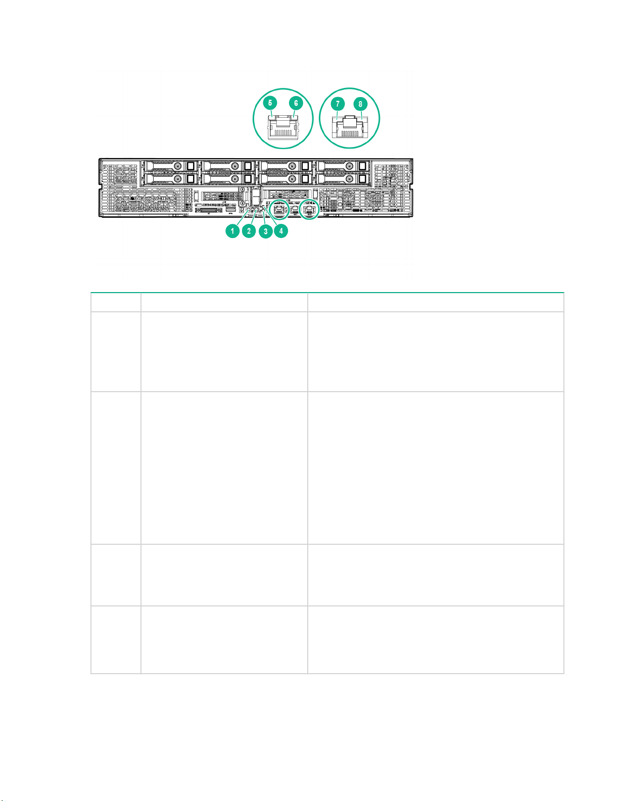
Front panel LEDs and buttons
Item Description Status
1
Power button/LED
2 UID button/LED
3 Health LED
1
1
Solid green = System on
Flashing green = Performing power on sequence
Solid amber = System in standby
Off = No power present
1
Solid blue = Activated
2
• 1 flash per second = Remote management or
firmware upgrade in progress
• 4 flashes per second = iLO manual soft reboot
sequence initiated
• 8 flashes per second = iLO manual hard reboot
sequence in progress
Off = Deactivated
Solid green = Normal
Flashing amber = System degraded
Flashing red = System critical
3
4
Do not remove LED Flashing white = Do not remove the node. Removing
8 Front panel LEDs and buttons
the node may terminate the current operation and
cause data loss.
Off = The node can be removed.
Table Continued
Page 9

Item Description Status
5
6
7 NIC link LED
8 NIC activity LED
1
When the LEDs described in this table flash simultaneously, a power fault has occurred. For more information, see
iLO activity LED Green or flashing green = Network activity
iLO link LED Green = Linked to network
1
1
Power Fault LEDs.
2
Facility power is not present, power cord is not attached, no power supplies are installed, power supply failure has
occurred, or the front I/O cable is disconnected.
3
If the health LED indicates a degraded or critical state, review the system IML or use iLO to review the system health
status.
Rear panel components
Off = No network activity
Off = No network connection
Green = Linked to network
Off = No network connection
Green or flashing green = Network activity
Off = No network activity
Item Description
1 Fan connectors
2 Management riser connector
3 DC power cable module connectors
Rear panel components 9
Page 10
Power fault LEDs
The following table provides a list of power fault LEDs, and the subsystems that are affected. Not all
power faults are used by all servers.
Subsystem LED behavior
System board 1 flash
Processor 2 flashes
Memory 3 flashes
Riser board PCIe slots 4 flashes
FlexibleLOM 5 flashes
Removable HPE Flexible Smart Array
controller/Smart SAS HBA controller
System board PCIe slots 7 flashes
Power backplane or storage backplane 8 flashes
Power supply 9 flashes
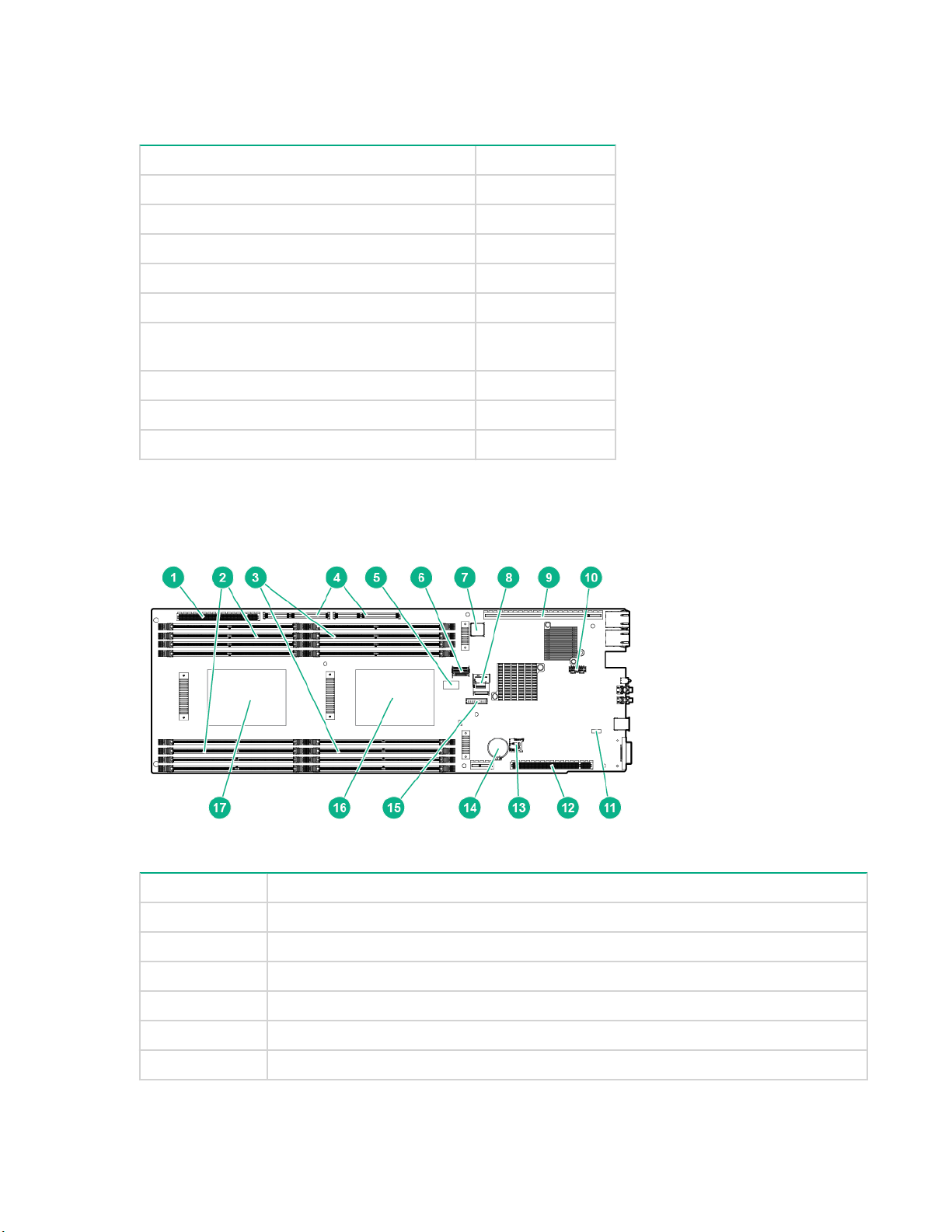
System board components
6 flashes
Item Description
1 Power riser connector
2 DIMMs for processor 2
3 DIMMs for processor 1
4 Right PCI riser module connector (PCIe x40)
5 System maintenance switch
6 Mini-SAS connector 1 (SATA x4)
10 Power fault LEDs
Table Continued
Page 11

Item Description
7 Internal USB 3.0 connector
8 Mini-SAS connector 2 (SATA x4)
9 Right PCI riser module connector (PCIe x24)
10 Dedicated iLO port connector
11 NMI header
12 Left PCI riser module connector (PCIe x16)
13 microSD slot
14 System battery
15 TPM connector
16 Processor 1
17 Processor 2
System maintenance switch
Position Default Function
S1 Off
S2 Off
S3 Off Reserved
S4 Off Reserved
S5 Off
S6 Off
S7 — Reserved
S8 — Reserved
Off = iLO security is enabled.
On = iLO security is disabled.
Off = System configuration can
be changed.
On = System configuration is
locked.
Off = Power-on password is
enabled.
On = Power-on password is
disabled.
Off = No function
On = ROM reads system
configuration as invalid.
S9 — Reserved
S10 — Reserved
S11 — Reserved
S12 — Reserved
System maintenance switch 11
Page 12

You can access the redundant ROM by setting S1, S5, and S6 to On.
When the system maintenance switch position 6 is set to the On position, the system is prepared to erase
all system configuration settings from both CMOS and NVRAM.
CAUTION:
Clearing CMOS, NVRAM, or both deletes configuration information. Be sure to configure the server
properly to prevent data loss.
NMI functionality
An NMI crash dump creates a crash dump log before resetting a system which is not responding.
Crash dump log analysis is an essential part of diagnosing reliability problems, such as failures of
operating systems, device drivers, and applications. Many crashes freeze a system, and the only
available action for administrators is to restart the system. Resetting the system erases any information
which could support problem analysis, but the NMI feature preserves that information by performing a
memory dump before a system reset.
To force the system to invoke the NMI handler and generate a crash dump log, do one of the following:
• Use the iLO Virtual NMI feature.
•
Short the NMI header.
For more information, see the Hewlett Packard Enterprise website.
DIMM slot locations
DIMM slots are numbered sequentially (1 through 8) for each processor. The supported AMP modes use
the letter assignments for population guidelines.
NOTE: The arrow indicates the front of the server.
12 NMI functionality
Page 13
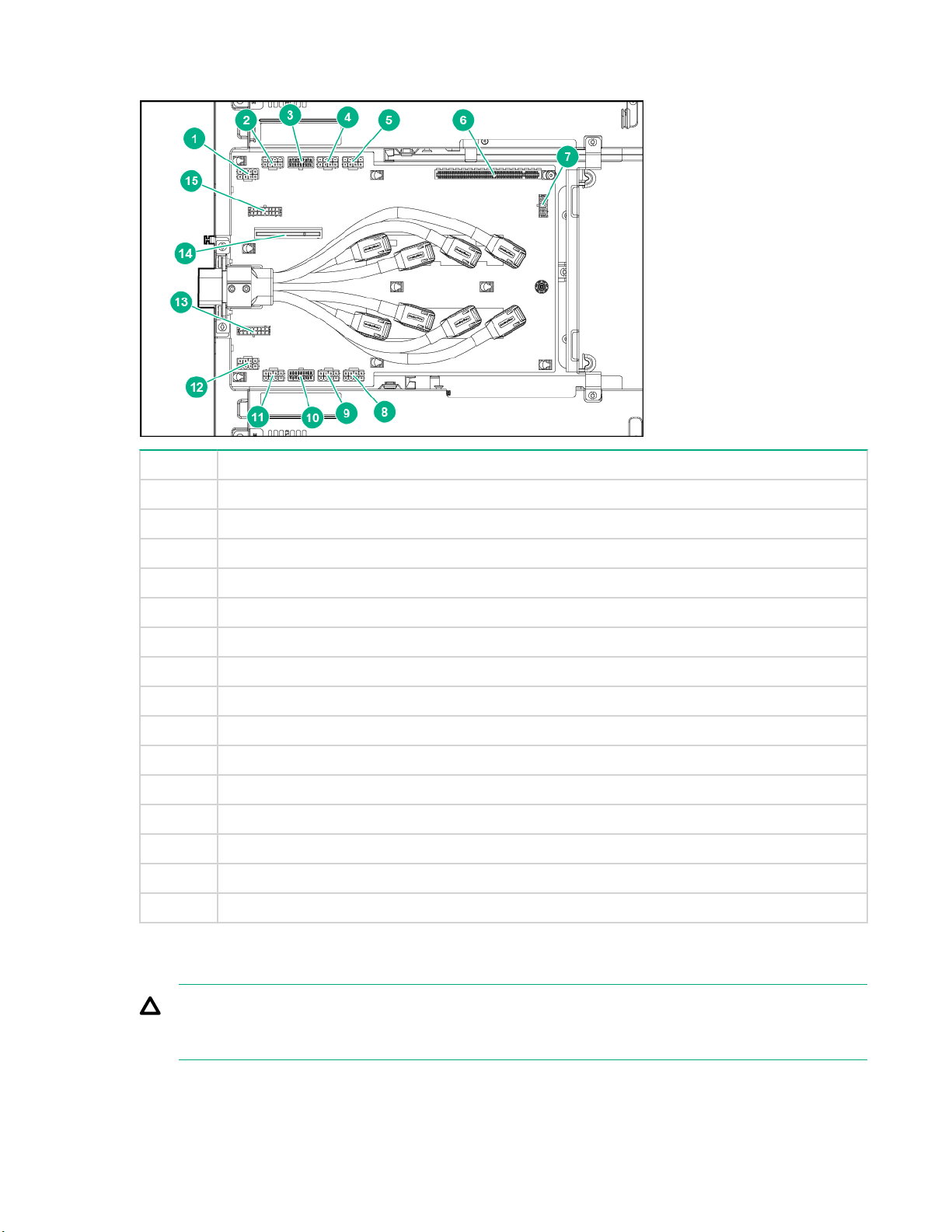
Power distribution board components
Item Description
1 GPU 8 power connector
2 GPU 7 power conector
3 Right PCI riser module power connector
4 GPU 6 power connector
5 GPU 5 power connector
6 Power riser connector
7 Drive backplane power connector
8 GPU 1 power connector
9 GPU 2 power connector
10 Left PCI riser module power connector
11 GPU 3 power connector
12 GPU 4 power connector
13 Left fan power connector
14 Management riser slot
15 Right fan power connector
Drive bay numbering
CAUTION:
To prevent improper cooling and thermal damage, do not operate the chassis unless all bays are
populated with a component or a blank.
Power distribution board components 13
Page 14
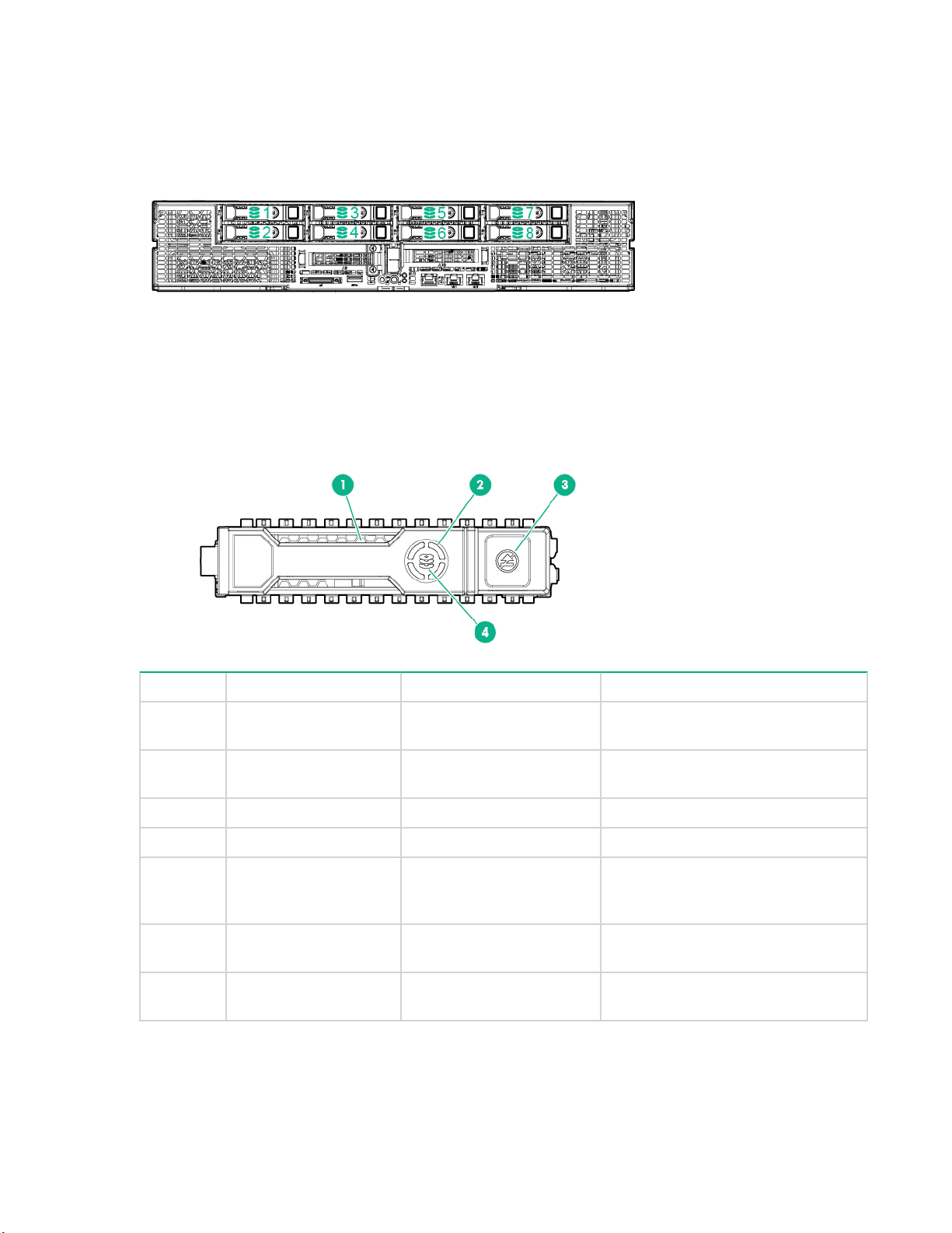
Hot-plug drive LED definitions
Item LED Status Definition
1 Locate Solid blue The drive is being identified by a
Flashing blue The drive carrier firmware is being
2 Activity ring Rotating green Drive activity.
Off No drive activity.
3 Do not remove Solid white Do not remove the drive. Removing
host application.
updated or requires an update.
the drive causes one or more of the
logical drives to fail.
Off Removing the drive does not cause
4 Drive status Solid green The drive is a member of one or
14 Hot-plug drive LED definitions
a logical drive to fail.
more logical drives.
Table Continued
Page 15

Item LED Status Definition
Flashing green The drive is rebuilding or performing
a RAID migration, strip size
migration, capacity expansion, or
logical drive extension, or is erasing.
Flashing amber/green The drive is a member of one or
more logical drives and predicts the
drive will fail.
Flashing amber The drive is not configured and
predicts the drive will fail.
Solid amber The drive has failed.
Off The drive is not configured by a
RAID controller.
IMPORTANT:
The Dynamic Smart Array B140i Controller is only available in UEFI Boot Mode. It cannot be
enabled in Legacy BIOS Boot Mode. If the B140i controller is disabled, drives connected to the
system board Mini-SAS connectors operate in AHCI or Legacy mode. Under this condition:
• The drives cannot be a part of a hardware RAID or a logical drive.
• The Locate, Drive status, and Do not remove LEDs of the affected drives are disabled.
Use BIOS/Platform Configuration (RBSU) in the UEFI System Utilities to enable or disable the
B140i controller (System Configuration ® BIOS/Platform Configuration (RBSU) ® System Options
®
SATA Controller Options ® Embedded SATA Configuration).
GPU accelerator numbering
• Server left GPU accelerator numbering
GPU accelerator numbering 15
Page 16

Item Description
1 GPU 1
2 GPU 2
3 GPU 3
4 GPU 4
• Server right GPU accelerator numbering
Item Description
5 GPU 5
6 GPU 6
7 GPU 7
8 GPU 8
NOTE: The arrow indicates the front of the server.
PCI riser module components
• Right 8:1 PCI riser module
16 PCI riser module components
Page 17

Item Description
1 Riser module power connector
2 8:1 sideband cable connector
3 Right 8:1 interposer board
4 Storage backup power connector
5 Slot 10 PCIe3 x16 (16, 8, 4, 1) for Processor 1
6 GPU sllot 7 PCIe3 x16 (16, 8, 4, 1) for Processor 1
7 GPU slot 8 PCIe3 x16 (16, 8, 4, 1) for Processor 1
8 Right 8:1 GPU riser board
9 GPU slot 5 PCIe3 x16 (16, 8, 4, 1) for Processor 1
10 GPU slot 6 PCIe3 x16 (16, 8, 4, 1) for Processor 1
11 Slot 11 PCIe3 x16 (16, 8, 4, 1) for Processor 1
• Left 8:1 PCI riser module
Component identification 17
Page 18

Slot number Slot description
1 Storage backup power connector
2 Slot 9 PCIe3 x16 (16, 8, 4, 1) for Processor 1
3 Left 8:1 interposer board
4 8:1 sideband cable connector
5 Riser module power connector
6 GPU slot 4 PCIe3 x16 (16, 8, 4, 1) for Processor 1
7 GPU slot 3 PCIe3 x16 (16, 8, 4, 1) for Processor 1
8 Left 8:1 GPU riser board
9 GPU slot 2 PCIe3 x16 (16, 8, 4, 1) for Processor 1
10 GPU slot 1 PCIe3 x16 (16, 8, 4, 1) for Processor 1
• Right 4:1 PCI riser module
18 Component identification
Page 19

Item Description
1 Riser module power connector
2 4:1 riser signal cable connector
3 Right 4:1 interposer board
4 Storage backup power connector
5 Slot 10 PCIe3 x16 (16, 8, 4, 1) for Processor 2
6 GPU slot 7 PCIe3 x16 (16, 8, 4, 1) for Processor 2
7 GPU slot 8 PCIe3 x16 (16, 8, 4, 1) for Processor 2
8 Right 4:1 GPU riser board
9 GPU slot 5 PCIe3 x16 (16, 8, 4, 1) for Processor 2
10 GPU slot 6 PCIe3 x16 (16, 8, 4, 1) for Processor 2
11 Slot 11 PCIe3 x16 (16, 8, 4, 1) for Processor 1
• Left 4:1 PCI riser module
Item Description
1 Storage backup power connector
2 Slot 9 PCIe3 x16 (16, 8, 4, 1) for Processor 1
3 Left 4:1 interposer board
4 4:1 riser signal connector
5 Riser module power connector
6 GPU slot 4 PCIe3 x16 (16, 8, 4, 1) for Processor 1
7 GPU slot 3 PCIe3 x16 (16, 8, 4, 1) for Processor 1
8 Left 4:1 GPU riser board
Table Continued
Component identification 19
Page 20

9 GPU slot 2 PCIe3 x16 (16, 8, 4, 1) for Processor 1
10 GPU slot 1 PCIe3 x16 (16, 8, 4, 1) for Processor 1
20 Component identification
Page 21

Operations
Powering up the server
The SL/XL Chassis Firmware initiates an automatic power-up sequence when the servers are installed. If
the default setting is changed, use one of the following methods to power up each server:
• Use a virtual power button selection through iLO .
• Press and release the Power On/Standby button.
When the server goes from the standby mode to the full power mode, the server power LED changes
from amber to green.
For more information about iLO , see the
Powering down the server
Before powering down the server for any upgrade or maintenance procedures, perform a backup of
critical server data and programs.
CAUTION:
Before powering down the server, perform a backup of critical server data and programs. Removing
the server while the Do not remove LED is on may result in data loss or corruption. The server can
be safely removed from the chassis only after the Do not remove LED is off.
IMPORTANT:
When the server is in standby mode, auxiliary power is still being provided to the system.
To power down the server , use one of the following methods:
• Press and release the Power On/Standby button.
This method initiates a controlled shutdown of applications and the OS before the server enters
standby mode.
• Press and hold the Power On/Standby button for more than 4 seconds to force the server to enter
standby mode.
Hewlett Packard Enterprise website.
This method forces the server to enter standby mode without properly exiting applications and the OS.
If an application stops responding, you can use this method to force a shutdown.
• Use a virtual power button selection through iLO .
This method initiates a controlled remote shutdown of applications and the OS before the server
enters standby mode.
Before proceeding, verify that the server is in standby mode by observing that the system power LED is
amber.
Operations 21
Page 22
Removing the server from the chassis
CAUTION:
Before powering down the server, perform a backup of critical server data and programs. Removing
the server while the Do not remove LED is on may result in data loss or corruption. The server can
be safely removed from the chassis only after the Do not remove LED is off.
CAUTION:
To avoid damage to the server , always support the bottom of the server when removing it from the
server .
Procedure
1. Back up all server data.
2. Power down the server .
3. Disconnect all peripheral cables from the server front panel.
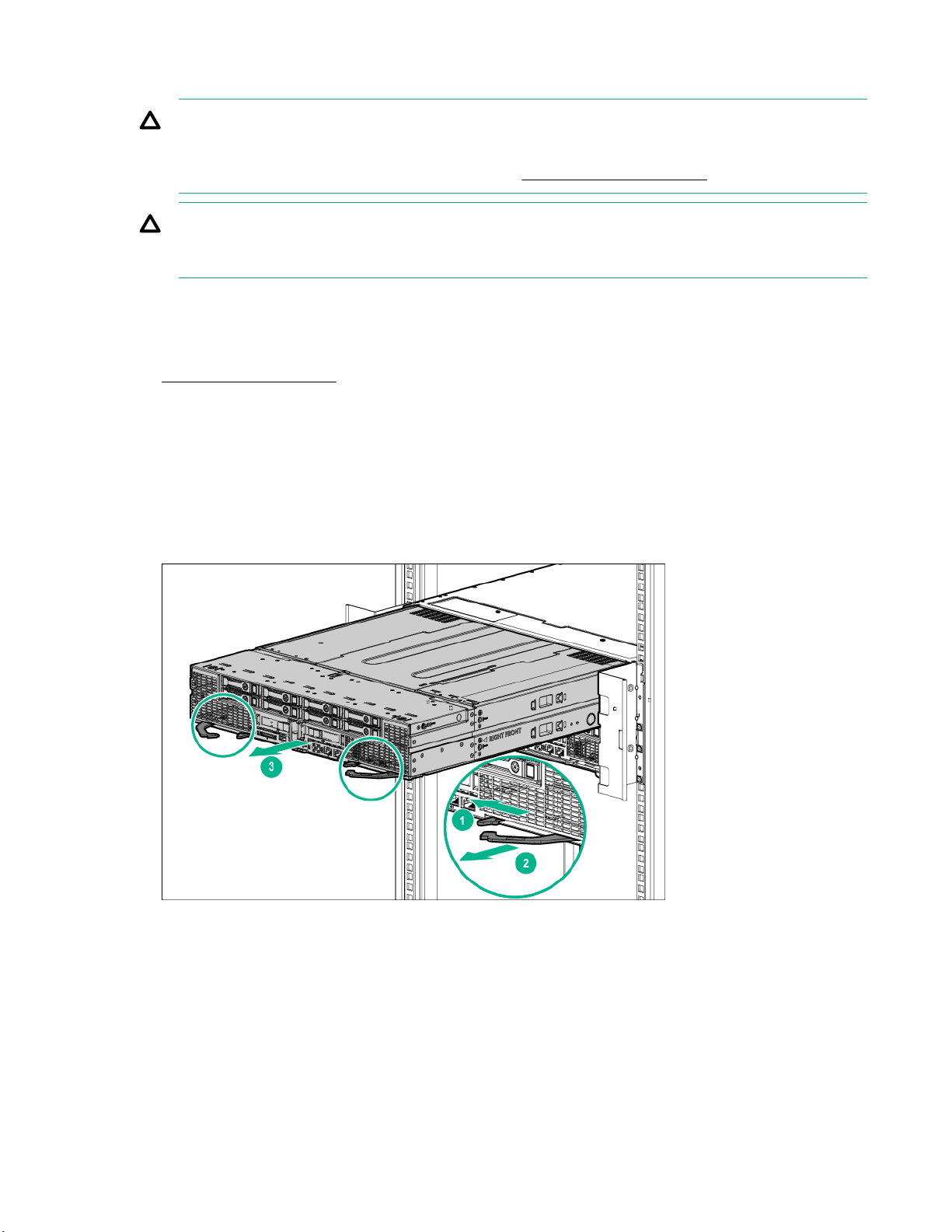
4. Extend the server from the chassis:
a. Release the safety latches.
b. Pull back the handles.
c. Extend the server from the chassis until the server locks are engaged.
5. Remove the server from the chassis:
a. Press on the server release latches.
b. Slide the server out of the chassis.
22 Removing the server from the chassis
Page 23
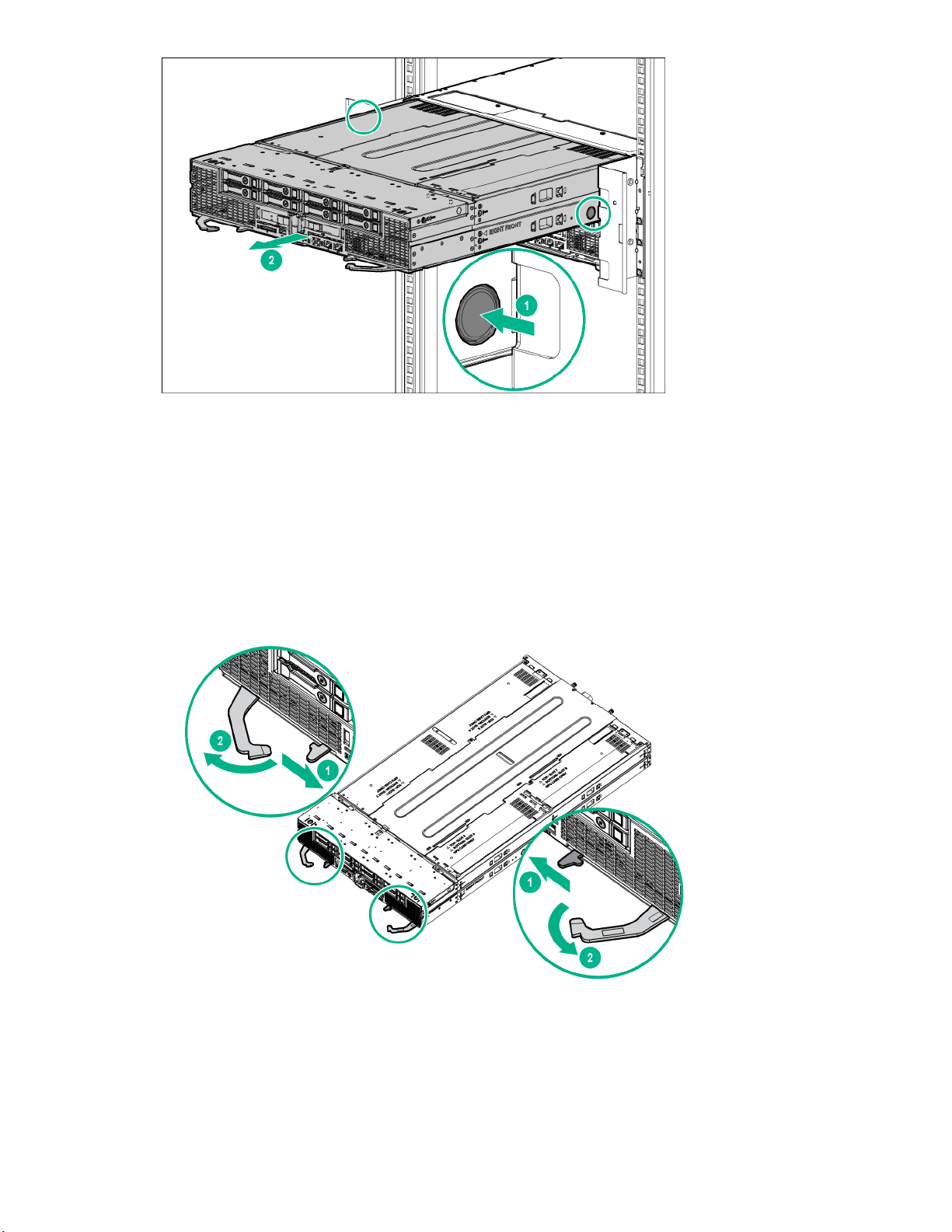
6. Place the server on a sturdy, level surface.
Installing the server into the chassis
Procedure
1. Prepare the server:
a. Release the safety latches.
b. Pull back the handles.
2. Install the server into the chassis:
a. Slide the server into the chassis.
b. Secure the handles in the safety latches.
Installing the server into the chassis 23
Page 24

3. Connect all peripheral cables to the server .
4. Power up the server .
Removing the access panel
Procedure
1. Back up all server data.
2. Power down the server .
3. Disconnect all peripheral cables from the server .
4. Remove the server from the chassis.
5. Place the server on a sturdy, level surface.
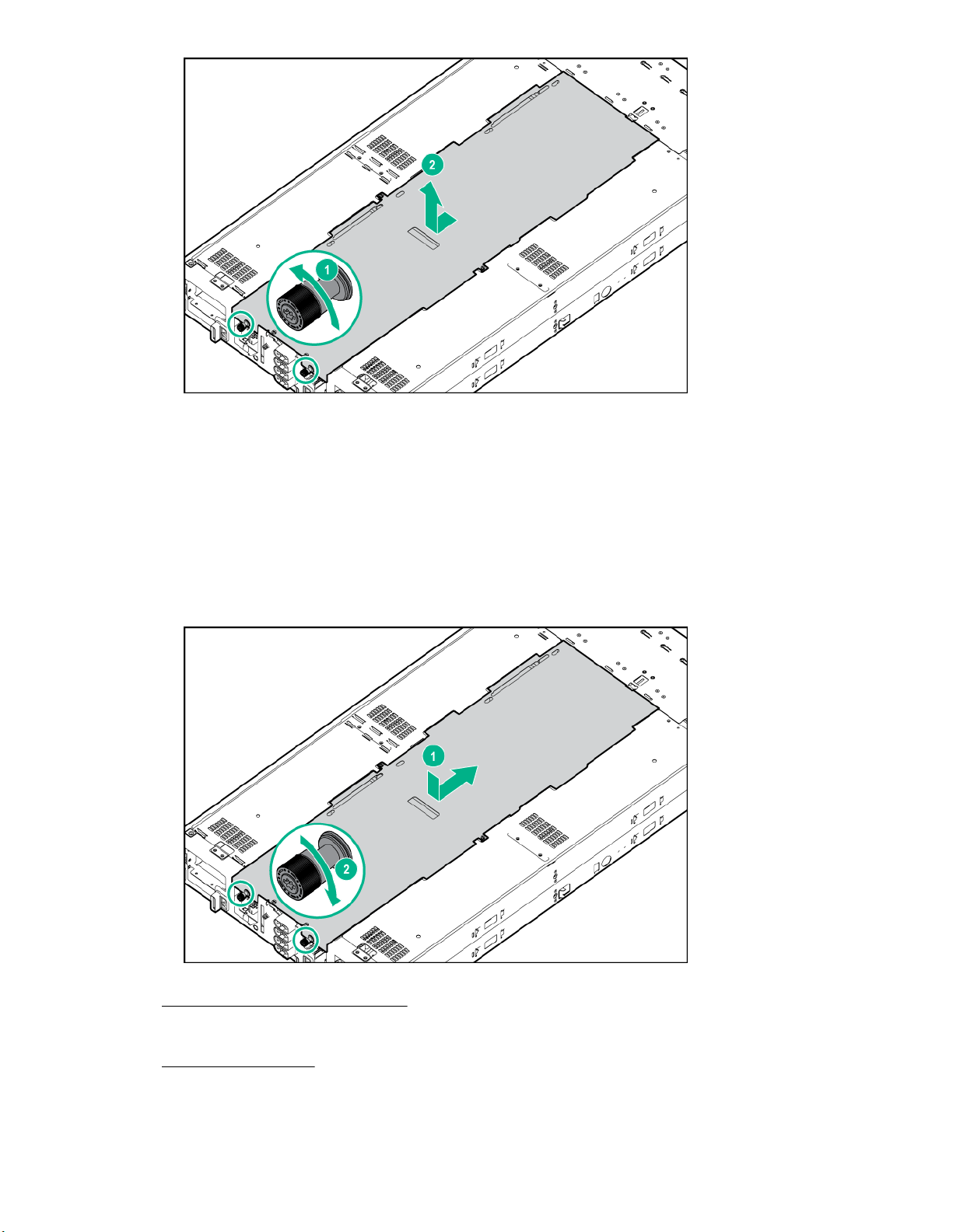
6. Remove the access panel:
a. Loosen the thumbscrews.
b. Slide the access panel towards the rear and lift it from the server.
24 Removing the access panel
Page 25
Installing the access panel
Procedure
1. Install the access panel:
a. Place the access panel on top of the server and slide it into place.
b. Tighten the thumbscrews.
2. Install the server into the chassis.
3. Connect all peripheral cables to the server .
4. Power up the server .
Installing the access panel 25
Page 26
Removing the side panel
Procedure
1. Back up all server data.
2. Power down the server .
3. Disconnect all peripheral cables from the server .
4. Remove the server from the chassis .
5. Place the server on a sturdy, level surface.
NOTE: To access GPU slots 1 to 4, remove the left side panel. To access GPU slots 5 to 8,
remove the right side panel.
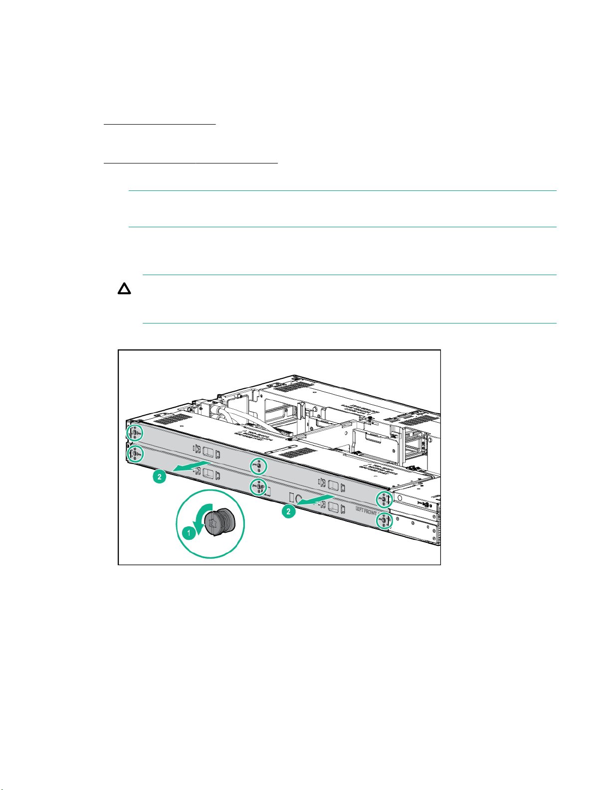
6. Remove the side panel:
a. Loosen the six captive screws.
CAUTION:
To prevent damage to the server or components, do not rotate the side panel downward or
upward.
b. Using both hands, hold the four notches and remove the side panel in a horizontal motion.
Installing the side panel
Procedure
1. Install the side panel:
26 Removing the side panel
Page 27

CAUTION:
To prevent damage to the server or components, do not rotate the side panel downward or
upward.
a. Using both hands, hold the four notches and install the side panel in a horizontal motion.
b. Tighten the six captive screws.
2. Install the server into the chassis.
3. Connect all peripheral cables to the server .
4. Power up the server .
Removing the air baffle
Procedure
1. Back up all server data.
2. Power down the server .
3. Disconnect all peripheral cables from the server .
4. Remove the server from the chassis.
5. Place the server on a sturdy, level surface.
6. Remove the access panel.
7. If a Smart Storage Battery is installed, disconnect the cable from the riser board.
Removing the air baffle 27
Page 28
8. If installed, disconnect the 4:1 riser signal cable:
a. Open the latches on the connectors.
b. Disconnect the cable from the connectors.
9. Remove the air baffle.
28 Operations
Page 29

Installing the air baffle
Install the air baffle
CAUTION:
To prevent damage to the server, ensure that all DIMM latches are in closed and locked position
before installing the air baffle.
Procedure
1. Install the air baffle.
2. If removed, connect the 4:1 riser signal cable:
a. Connect the cable to both the connectors.
b. Ensure that the latches are closed.
Installing the air baffle 29
Page 30

3. If a Smart Storage Battery is installed, reconnect the cable to the riser board.
4. Install the access panel.
5. Install the server into the chassis.
6. Connect all peripheral cables to the server.
7. Power up the server .
Removing the drive cage assembly
Procedure
1. Back up all server data.
2. Power down the server .
30 Removing the drive cage assembly
Page 31

3. Disconnect all peripheral cables from the server .
4. Remove the server from the chassis .
5. Place the server on a sturdy, level surface.
6. Remove the access panel.
7. Remove the air baffle.
8. Disconnect the cables from the drive backplane:
a. Disconnect the Mini-SAS cables.
b. Disconnect the power cable.
9. Remove the drive cage assembly:
a. Loosen the captive screws.
b. Slide the drive cage assembly towards the front and lift it from the server.
Operations 31
Page 32

Installing the drive cage assembly
Procedure
1. Install the drive cage assembly:
a. Lower the drive cage assembly into the server and slide it towards the rear to align the screw holes
with the captive screws.
b. Tighten the captive screws.
2. Connect the cables to the drive backplane.
32 Installing the drive cage assembly
Page 33

3. Install the air baffle.
If the 4:1 riser signal cable or Smart Storage Battery are installed in the air baffle, reconnect the cables
to the risers. For more information, see "
4. Install the access panel.
5. Install the server into the chassis.
6. Connect all peripheral cables to the server .
7. Power up the server .
Installing the air baffle."
Operations 33
Page 34

Setup
Optional service
Delivered by experienced, certified engineers, HPE support services help you keep your servers up and
running with support packages tailored specifically for HPE ProLiant systems. HPE support services let
you integrate both hardware and software support into a single package. A number of service level
options are available to meet your business and IT needs.
HPE support services offer upgraded service levels to expand the standard product warranty with easyto-buy, easy-to-use support packages that will help you make the most of your server investments. Some
of the HPE support services for hardware, software or both are:
• Foundation Care – Keep systems running.
◦ 6-Hour Call-to-Repair
◦ 4-Hour 24x7
◦ Next Business Day
• Proactive Care – Help prevent service incidents and get you to technical experts when there is one.
◦ 6-Hour Call-to-Repair
◦ 4-Hour 24x7
◦ Next Business Day
• Deployment service for both hardware and software
• HPE Education Services – Help train your IT staff.
1
The time commitment for this repair service might vary depending on the site's geographical region. For
more service information available in your site, contact your local
For more information on HPE support services, see the Hewlett Packard Enterprise website.
1
1
Server warnings and cautions
HPE support center.
34 Setup
WARNING:
This server is very heavy. To reduce the risk of personal injury or damage to the equipment:
• Observe local occupational health and safety requirements and guidelines for manual handling.
• Reduce the weight of the server by removing the drives before installing or removing the server
from the chassis.
• Obtain adequate assistance to lift and stabilize the server during installation or removal. Hewlett
Packard Enterprise recommends that a minimum of two people are required for installing or
removing the server from the chassis. A third person might be required to help align the server if
the server is installed higher than chest level.
• Use caution when installing or removing the server from the chassis; it is unstable when the
server locks are not engaged with the chassis.
Page 35

WARNING:
To reduce the risk of personal injury from hot surfaces, allow the drives and the internal system
components to cool before touching them.
CAUTION:
Electrostatic discharge can damage electronic components. Be sure you are properly grounded
before beginning this procedure.
CAUTION:
For proper cooling, do not operate the server without the access panel, baffles, expansion slot
covers, or blanks installed. If the server supports hot-plug components, minimize the amount of time
the access panel is open.
Server shipping carton contents
Unpack the server shipping carton and locate the materials and documentation necessary for installing
the server. All the rack mounting hardware necessary for installing the server into the rack is included with
the rack or the server.
The contents of the server shipping carton include:
• Server
• Printed setup documentation
• Accessory kit
Prerequisites for installing the options
In addition to the supplied items, you might need:
• T-25 Torx screwdriver (to secure the chassis in the rack)
• T-10/T-15 Torx screwdriver
• Flathead screwdriver (to remove the knockout on the dedicated iLO connector opening)
• Hardware options
Installation overview
Installation of a server requires the following steps:
1. Install the chassis into a rack.
2. Install any server options .
3. Install the server into the chassis.
4. Install an operating system.
5. Install system software.
6. Register the product.
Server shipping carton contents 35
Page 36

Installing the chassis into a rack
To install the server into a rack, see the Setup and Installation Guide on the Hewlett Packard Enterprise
website. For more information, see the instructions included with the rail kit.
Installing hardware options
Before installing and initializing the server , install any hardware options. For options installation
information, see the documentation that ships with the option. For server -specific information, see
Hardware options installation."
"
Installing the operating system
To operate properly, the server must have a supported operating system installed. For the latest
information on operating system support, see the Hewlett Packard Enterprise website (http://
www.hpe.com/info/supportos).
IMPORTANT:
HPE ProLiant XL servers do not support operating system installation with Intelligent Provisioning,
but they do support the maintenance features. For more information, see "Performing Maintenance"
in the HPE Intelligent Provisioning User Guide and online help.
To install an operating system on the server , use one of the following methods:
• Manual installation—Insert the operating system CD into the USB-attached DVD-ROM drive (user
provided) and reboot the server. You must download the Service Pack for ProLiant from the SPP
download site (http://www.hpe.com/servers/spp/download) and create SPP media so that you can
install the drivers.
• Remote deployment installation—Use Insight Control server provisioning for an automated solution to
remotely deploy an operating system.
For additional system software and firmware updates, download the Service Pack for ProLiant from the
Hewlett Packard Enterprise website (http://www.hpe.com/servers/spp/download). Software and
firmware should be updated before using the node for the first time, unless any installed software or
components require an older version.
For more information on using these installation methods, see the Hewlett Packard Enterprise website
(http://www.hpe.com/info/ilo).
Installing the system software
To access and configure Intelligent Provisioning on a single server:
Procedure
1. Access Intelligent Provisioning by rebooting the server and pressing F10.
2. The first time you log into Intelligent Provisioning, follow the steps to set preferences and activate
Intelligent Provisioning.
3. From the Home screen, click Perform Maintenance, and then click Firmware Update.
4. Ensure the latest drivers are available for installation. Select Intelligent Provisioning Software from
the list of firmware, and click Update. If the check box is not selected, the latest drivers are already
installed.
36 Installing the chassis into a rack
Page 37

Registering the server
To experience quicker service and more efficient support, register the product at the Hewlett Packard
Enterprise Product Registration website.
Registering the server 37
Page 38

Hardware options installation
Product QuickSpecs
For more information about product features, specifications, options, configurations, and compatibility, see
the product QuickSpecs on the
Introduction
If more than one option is being installed, read the installation instructions for all the hardware options
and identify similar steps to streamline the installation process.
WARNING:
To reduce the risk of personal injury from hot surfaces, allow the drives and the internal system
components to cool before touching them.
NOTE: To prevent damage to electrical components, properly ground the server before beginning
any installation procedure. Improper grounding can cause electrostatic discharge.
Drive options
The embedded Dynamic Smart Array B140i Controller only supports SATA devices. For SAS drive
installation, install a Host Bus Adapter or a Smart Array Controller.
Hewlett Packard Enterprise website.
To accurately estimate the power consumption of the server and select the appropriate power
configuration and other system components, see the Hewlett Packard Enterprise Power Advisor
website.
For more information about product features, specifications, options, configurations, and compatibility, see
the product QuickSpecs on the Hewlett Packard Enterprise website.
Removing a drive blank
Remove the drive blank.
Installing a hot-plug drive
WARNING:
To reduce the risk of injury from electric shock, do not install more than one drive carrier at a time.
38 Hardware options installation
Page 39

Procedure
1. Remove the drive blank.
2. Prepare the drive.
3. Install the drive.
4. Determine the status of the drive from the drive LED definitions.
To configure arrays, see the HPE Smart Storage Administrator User Guide on the Hewlett Packard
Enterprise website.
Processor option
Processor and heatsink installation warnings and cautions
CAUTION:
To avoid damage to the processor and system board, only authorized personnel should attempt to
replace or install the processor in this server .
CAUTION:
To prevent possible server malfunction and damage to the equipment, multiprocessor configurations
must contain processors with the same part number.
CAUTION:
The heatsink thermal interface media is not reusable and must be replaced if the heatsink is
removed from the processor after it has been installed.
IMPORTANT:
Processor socket 1 must be populated at all times or the server does not function.
Processor option 39
Page 40

Installing the processor and heatsink
For more information about product features, specifications, options, configurations, and compatibility, see
the product QuickSpecs on the Hewlett Packard Enterprise website .
To install the component:
Procedure
1. Back up all server data.
2. Power down the server .
3. Disconnect all peripheral cables from the server .
4. Remove the server from the chassis .
5. Place the server on a sturdy, level surface.
6. Remove the access panel.
7. Remove the air baffle.
8. Open each of the processor locking levers in the order indicated in the following illustration, and then
open the processor retaining bracket.
9. Remove the clear processor socket cover. Retain the processor socket cover for future use.
40 Installing the processor and heatsink
Page 41

CAUTION:
To avoid damage to the processor, do not touch the bottom of the processor, especially the
contact area.
10. Install the processor. Verify that the processor is fully seated in the processor retaining bracket by
visually inspecting the processor installation guides on either side of the processor. THE PINS ON
THE SYSTEM BOARD ARE VERY FRAGILE AND EASILY DAMAGED.
CAUTION:
THE PINS ON THE SYSTEM BOARD ARE VERY FRAGILE AND EASILY DAMAGED. To
avoid damage to the system board, do not touch the processor or the processor socket
contacts.
Hardware options installation 41
Page 42

CAUTION:
Do not press down on the processor. Pressing down on the processor might damage the
processor socket and the system board. Press only in the area indicated on the processor
retaining bracket.
11. Close the processor retaining bracket. When the processor is installed properly inside the processor
retaining bracket, the processor retaining bracket clears the flange on the front of the socket.
12. Press and hold the processor retaining bracket in place, and then close each processor locking lever.
Press only in the area indicated on the processor retaining bracket.
CAUTION:
Always use a new heatsink when replacing processors. Failure to use new components can
cause damage to the processor.
13. Remove the thermal interface protective cover from the heatsink.
42 Hardware options installation
Page 43

CAUTION:
Heatsinks specified for processor 1 and 2 are not interchangeable. Be sure to note the
appropriate orientation on the heatsink label.
CAUTION:
Heatsink retaining screws should be tightened or loosened in diagonally opposite pairs (in an
"X" pattern). Do not overtighten the screws as this can damage the board, connectors, or
screws.
14. Install the heatsink:
a. Position the heatsink on the processor backplate.
b. Tighten one pair of diagonally opposite screws halfway, and then tighten the other pair of screws.
c. Finish the installation by completely tightening the screws in the same sequence.
15. Install the air baffle.
If the 4:1 riser signal cable or Smart Storage Battery are installed in the air baffle, reconnect the
cables to the risers. For more information, see "Installing the air baffle."
16. Install the access panel.
17. Install the server into the chassis.
18. Connect all peripheral cables to the server .
19. Power up the server .
Memory options
IMPORTANT:
This server does not support mixing LRDIMMs or RDIMMs. Attempting to mix any combination of
these DIMMs can cause the node to halt during BIOS initialization.
The memory subsystem in this node can support LRDIMMs and RDIMMs:
Memory options 43
Page 44

• RDIMMs offer address parity protection.
• LRDIMMs support higher densities than single- and dual-rank RDIMMs, and higher speeds than quadrank RDIMMs. This support enables you to install more high capacity DIMMs, resulting in higher
system capacities and higher bandwidth.
All types are referred to as DIMMs when the information applies to all types. When specified as LRDIMM
or RDIMM, the information applies to that type only. All memory installed in the node must be the same
type.
DIMM specifications
DIMM specifications
Type Rank Capacity (GB) Native speed
(MT/s)
RDIMM Single 8 2400 STD
RDIMM Single 16 2400 STD
RDIMM Dual 32 2400 STD
LRDIMM Dual 32 2400 STD
LRDIMM Quad 64 2400 STD
Populated DIMM speed (MT/s)
Operating memory speed is a function of rated DIMM speed, the number of DIMMs installed per channel,
processor model, and the speed selected in the BIOS/Platform Configuration (RBSU) of the UEFI
System Utilities
Type Rank 1 DIMM per channel
(MT/s)
RDIMM Single 2400 2133
RDIMM Dual 2400 2133
LRDIMM Dual 2400 2400
LRDIMM Quad 2400 2400
Voltage
2 DIMMs per channel
(MT/s)
Maximum memory capacity
Maximum memory capacity is a function of DIMM capacity, number of installed DIMMs, memory type, and
number of installed processors.
DIMM type DIMM rank Capacity (GB) Maximum
RDIMM Single-rank 8 64 128
RDIMM Single-rank 16 128 256
RDIMM Dual-rank 32 256 512
LRDIMM Dual-rank 32 256 512
LRDIMM Quad-rank 64 512 1024
44 DIMM specifications
capacity for one
processor (GB)
Maximum
capacity for two
processors (GB)
Page 45

SmartMemory
SmartMemory authenticates and unlocks certain features available only on Qualified memory and verifies
whether installed memory has passed Hewlett Packard Enterprise qualification and test processes.
Qualified memory is performance-tuned for ProLiant and BladeSystem servers and provides future
enhanced support through Active Health and manageability software.
Memory subsystem architecture
The memory subsystem in this server is divided into channels. Each processor supports four channels,
and each channel supports two DIMM slots, as shown in the following table.
Channel Population order Slot number
1 A 8
E 7
2 B 6
F 5
3 C 1
G 2
4 D 3
H 4
Single-, dual-, and quad-rank DIMMs
To understand and configure memory protection modes properly, an understanding of single-, dual-, and
quad-rank DIMMs is helpful. Some DIMM configuration requirements are based on these classifications.
A single-rank DIMM has one set of memory chips that is accessed while writing to or reading from the
memory. A dual-rank DIMM is similar to having two single-rank DIMMs on the same module, with only
one rank accessible at a time. A quad-rank DIMM is, effectively, two dual-rank DIMMs on the same
module. Only one rank is accessible at a time. The node memory control subsystem selects the proper
rank within the DIMM when writing to or reading from the DIMM.
Dual- and quad-rank DIMMs provide the greatest capacity with the existing memory technology. For
example, if current DRAM technology supports 8-GB single-rank DIMMs, a dual-rank DIMM would be 16
GB, and a quad-rank DIMM would be 32 GB.
LRDIMMs are labeled as quad-rank DIMMs. There are four ranks of DRAM on the DIMM, but the
LRDIMM buffer creates an abstraction that allows the DIMM to appear as a dual-rank DIMM to the
system. The LRDIMM buffer isolates the electrical loading of the DRAM from the system to allow for
faster operation. This allows higher memory operating speed compared to quad-rank RDIMMs.
DIMM identification
To determine DIMM characteristics, use the label attached to the DIMM and the following illustration and
table.
SmartMemory 45
Page 46

Item Description Definition
1 Capacity
2 Rank
3 Data width
4 Memory generation
5 Maximum memory speed
6 CAS latency
7 DIMM type
4 GB
8 GB
16 GB
32 GB
1R = Single-rank
2R = Dual-rank
4R = Quad-rank
x4 = 4-bit
x8 = 8-bit
DDR4
2133 MT/s
P=15
R = RDIMM (registered)
L = LRDIMM (load reduced)
Memory configurations
To optimize server availability, the server supports the following AMP modes:
• Advanced ECC—Provides up to 4-bit error correction and enhanced performance over Lockstep
mode. This mode is the default option for this server .
• Online spare memory—Provides protection against failing or degraded DIMMs. Certain memory is
reserved as spare, and automatic failover to spare memory occurs when the system detects a DIMM
that is degrading. This allows DIMMs that have a higher probability of receiving an uncorrectable
memory error (which would result in system downtime) to be removed from operation.
Advanced Memory Protection options are configured in the BIOS/Platform Configuration (RBSU). If the
requested AMP mode is not supported by the installed DIMM configuration, the server boots in Advanced
46 Memory configurations
Page 47

ECC mode. For more information, see the HPE UEFI System Utilities User Guide for ProLiant Gen9
Servers on the Hewlett Packard Enterprise website.
Advanced ECC memory configuration
Advanced ECC memory is the default memory protection mode for this server . Standard ECC can
correct single-bit memory errors and detect multi-bit memory errors. When multi-bit errors are detected
using Standard ECC, the error is signaled to the server and causes the server to halt.
Advanced ECC protects the server against some multi-bit memory errors. Advanced ECC can correct
both single-bit memory errors and 4-bit memory errors if all failed bits are on the same DRAM device on
the DIMM.
Advanced ECC provides additional protection over Standard ECC because it is possible to correct certain
memory errors that would otherwise be uncorrected and result in a server failure. Using HPE Advanced
Memory Error Detection technology, the server provides notification when a DIMM is degrading and has a
higher probability of uncorrectable memory error.
Online Spare memory configuration
Online spare memory provides protection against degraded DIMM s by reducing the likelihood of
uncorrected memory errors. This protection is available without any operating system support.
Online spare memory protection dedicates one rank of each memory channel for use as spare memory.
The remaining ranks are available for OS and application use. If correctable memory errors occur at a
rate higher than a specific threshold on any of the non-spare ranks, the server automatically copies the
memory contents of the degraded rank to the online spare rank. The server then deactivates the failing
rank and automatically switches over to the online spare rank.
General DIMM slot population guidelines
Observe the following guidelines for all AMP modes:
• Install DIMMs only if the corresponding processor is installed.
• When two processors are installed, balance the DIMMs across the two processors.
• White DIMM slots denote the first slot of a channel (Ch 1-A, Ch 2-B, Ch 3-C, Ch 4-D)
• Do not mix RDIMMs and LRDIMMs.
• When one processor is installed, install DIMMs in sequential alphabetic order: A, B, C, D, E, F, and so
forth.
• When two processors are installed, install the DIMMs in sequential alphabetic order balanced between
the two processors: P1-A, P2-A, P1-B, P2-B, P1-C, P2-C, and so forth.
• When single-rank, dual-rank, and quad-rank DIMMs are populated for two DIMMs per channel or three
DIMMs per channel, always populate the higher number rank DIMM first (starting from the farthest
slot). For example, first quad-rank DIMM, then dual-rank DIMM, and then lastly single-rank DIMM.
• DIMMs should be populated starting farthest from the processor on each channel.
• For DIMM spare replacement, install the DIMMs per slot number as instructed by the system software.
For more information about server memory, see the Hewlett Packard Enterprise website.
Advanced ECC population guidelines
For Advanced ECC mode configurations, observe the following guidelines:
Advanced ECC memory configuration 47
Page 48

• Observe the general DIMM slot population guidelines.
• DIMMs may be installed individually.
Online spare population guidelines
For Online Spare memory mode configurations, observe the following guidelines:
• Observe the general DIMM slot population guidelines.
• Each channel must have a valid online spare configuration.
• Each channel can have a different valid online spare configuration.
• Each populated channel must have a spare rank. A single dual-rank DIMM is not a valid configuration.
Population order
For memory configurations with a single processor or multiple processors, DIMMs must be populated
sequentially in alphabetical order (A through H).
After installing the DIMMs, use the BIOS/Platform Configuration (RBSU) in the UEFI System Utilities to
configure supported AMP modes.
Installing a DIMM
Procedure
1. Back up all server data.
2. Power down the server .
3. Disconnect all peripheral cables from the server .
4. Remove the server from the chassis .
5. Place the server on a sturdy, level surface.
6. Remove the access panel.
7. Remove the air baffle.
8. Open the DIMM slot latches.
9. Install the DIMM.
48 Online spare population guidelines
Page 49

CAUTION:
To prevent damage to the server, ensure that all DIMM latches are in closed and locked
position before installing the air baffle.
10. Install the air baffle.
If the 4:1 riser signal cable or Smart Storage Battery are installed in the air baffle, reconnect the
cables to the risers. For more information, see "Installing the air baffle."
11. Install the access panel.
12. Install the server into the chassis.
13. Connect all peripheral cables to the server .
14. Power up the server .
PCI riser module options
For more information on installing GPU accelerators, see "GPU accelerator options."
For more information about product features, specifications, options, configurations, and compatibility, see
the product QuickSpecs on the Hewlett Packard Enterprise website .
Installing the 4:1 PCI riser modules
To install the component:
Procedure
1. Back up all server data.
2. Power down the server .
3. Disconnect all peripheral cables from the server front panel.
4. Remove the server from the chassis .
5. Place the server on a sturdy, level surface.
6. Remove the access panel.
PCI riser module options 49
Page 50

7. If installed, remove the Smart Storage Battery:
a. Disconnect the cable from the riser connector.
b. Pull back the release clip.
c. Lift the Smart Storage Battery from the holder.
8. Remove the air baffle.
IMPORTANT:
Remove all GPUs, GPU blanks, and expansion boards before removing the PCI riser modules.
9. Remove the side panel.
10. Remove all GPUs:
a. Loosen the captive screw.
b. Using both hands, gently pull the tab and the rear support bracket to slide out the GPU to access
the power cable.
50 Hardware options installation
Page 51

c. Disconnect the power cable from the GPU, and then remove the GPU from the server.
11. Remove all GPU blanks:
a. Loosen the captive screw.
b. Using both hands, gently pull the tab and the rear of the GPU blank.
c. Slide out the GPU blank from the server.
12. Remove the drive cage assembly.
13. Remove all expansion boards:
a. Disconnect any internal cables that are connected to the riser modules.
b. Remove the expansion board.
Hardware options installation 51
Page 52

• Slot 9
• Slot 10
14. If installed, remove the HPE Smart Array P542D controller module:
a. Pull up the pin.
b. Rotate the handle counter-clockwise.
52 Hardware options installation
Page 53

c. Push down the pin.
d. Slide the module out of the PCIe slot and remove it from the server.
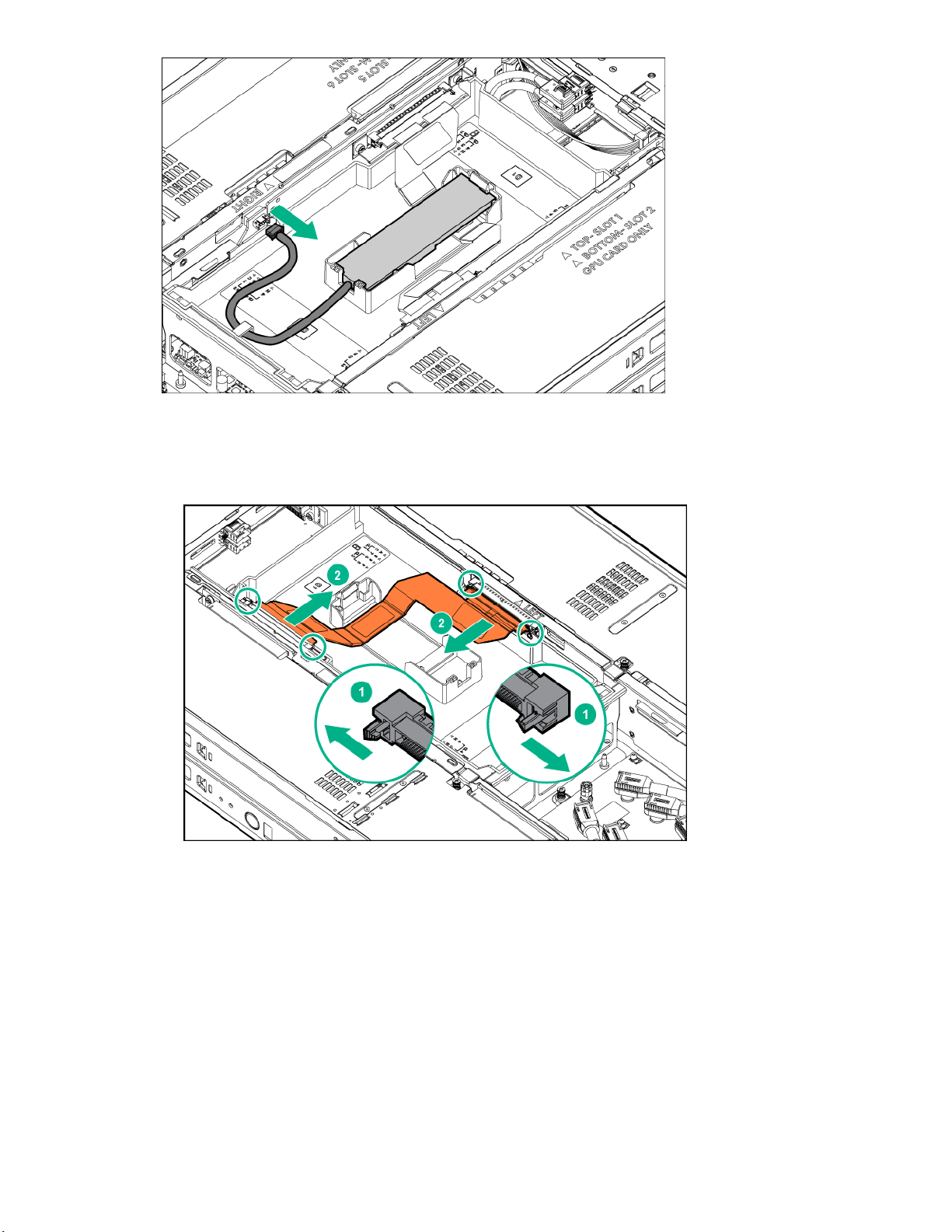
15. Disconnect and remove the 8:1 riser sideband cable.
Hardware options installation 53
Page 54

16. Disconnect the power cables from the 8:1 risers.
17. Remove the riser cross bracket:
a. Loosen the captive screws.
b. Remove the bracket from the server.
54 Hardware options installation
Page 55

18. Remove the power riser.
19. Remove the right 8:1 PCI riser module:
a. Loosen the captive screw.
b. Using both hands, lift and remove the PCI riser module from the server.
Hardware options installation 55
Page 56

20. Remove the left 8:1 PCI riser module:
a. Loosen the captive screw.
b. Using both hands, lift and remove the PCI riser module from the server.
21. Install the left 4:1 PCI riser module:
a. Slide the PCI riser module into the server, and then use both hands to press downward to secure
the PCI riser module in the connectors.
b. Tighten the captive screw.
56 Hardware options installation
Page 57

22. Install the right 4:1 PCI riser module:
a. Slide the PCI riser module into the server, and then use both hands to press downward to secure
the PCI riser module in the connectors.
b. Tighten the captive screw.
23. Install the power riser.
Hardware options installation 57
Page 58

24. Install the riser cross bracket:
a. Align the captive screws with the screw holes.
b. Tighten the captive screws.
25. Connect the power cables to the right and left PCI riser modules.
58 Hardware options installation
Page 59

26. If removed, install the HPE Smart Array P542D controller module.
27. If removed,
28. Connect any required internal cables.
29. Install the drive cage assembly.
30. Connect all cables to the drive backplane.
31. Install all GPUs and GPU blanks.
32. Install the side panel.
33. Install the air baffle.
34. Route and connect the 4:1 riser signal cable:
a. Connect the cable to both connectors.
b. Ensure that the latches are closed.
install the expansion board.
Hardware options installation 59
Page 60

35. If removed, install the Smart Storage Battery and connect the cable to the riser connector.
36. Install the access panel.
37. Install the server into the chassis.
38. Connect all peripheral cables to the server .
39. Power up the server .
Installing the 8:1 PCI riser modules
To install the component:
Procedure
1. Back up all server data.
2. Power down the server .
3. Disconnect all peripheral cables from the server front panel.
4. Remove the server from the chassis .
5. Place the server on a sturdy, level surface.
6. Remove the access panel.
7. If installed, remove the Smart Storage Battery:
a. Disconnect the cable from the riser connector.
b. Pull back the release clip.
c. Lift the Smart Storage Battery from the holder.
8. Disconnect and remove the 4:1 riser signal cable.
60 Installing the 8:1 PCI riser modules
Page 61

9. Remove the air baffle.
IMPORTANT:
Remove all GPUs, GPU blanks, and expansion boards before removing the PCI riser modules.
10. Remove the side panel.
11. Remove all GPUs:
a. Loosen the captive screw.
b. Using both hands, gently pull the tab and the rear support bracket to slide out the GPU to access
the power cable.
c. Disconnect the power cable from the GPU, and then remove the GPU from the server.
12. Remove all GPU blanks:
Hardware options installation 61
Page 62

a. Loosen the captive screw.
b. Using both hands, gently pull the tab and the rear of the GPU blank.
c. Slide out the GPU blank from the server.
13. Remove the drive cage assembly.
14. Remove all expansion boards:
a. Disconnect any internal cables that are connected to the riser modules.
b. Remove the expansion board.
• Slot 9
• Slot 10
62 Hardware options installation
Page 63

15. If installed, remove the HPE Smart Array P542D controller module:
a. Pull up the pin.
b. Rotate the handle counter-clockwise.
c. Push down the pin.
d. Slide the module out of the PCIe slot and remove it from the server.
Hardware options installation 63
Page 64

16. Disconnect the power cables from the 4:1 risers.
17. Remove the riser cross bracket:
a. Loosen the captive screws.
b. Remove the bracket from the server.
64 Hardware options installation
Page 65

18. Remove the power riser.
19. Remove the right 4:1 PCI riser module:
a. Loosen the captive screw.
b. Using both hands, lift and remove the PCI riser module from the server.
Hardware options installation 65
Page 66

20. Remove the left 4:1 PCI riser module:
a. Loosen the captive screw.
b. Using both hands, lift and remove the PCI riser module from the server.
21. Install the left 8:1 PCI riser module:
a. Slide the PCI riser module into the server, and then use both hands to press downward to secure
the PCI riser module in the connectors.
b. Tighten the captive screw.
66 Hardware options installation
Page 67

22. Install the right 8:1 PCI riser module:
a. Slide the PCI riser module into the server, and then use both hands to press downward to secure
the PCI riser module in the connectors.
b. Tighten the captive screw.
23. Install the power riser.
Hardware options installation 67
Page 68

24. Install the riser cross bracket:
a. Align the captive screws with the screw holes.
b. Tighten the captive screws.
25. Connect the power cables to the right and left PCI riser modules.
68 Hardware options installation
Page 69

26. If removed, install the HPE Smart Array P542D controller module.
27. If removed,
28. Connect any required internal cables.
29. Install the drive cage assembly.
30. Connect all cables to the drive backplane.
31. Install all GPUs and GPU blanks.
32. Install the side panel.
33. Connect the 8:1 riser sideband cable to the 8:1 PCI riser modules.
install the expansion board.
34. Install the air baffle.
35. If removed, install the Smart Storage Battery and connect the cable to the riser connector.
36. Install the access panel.
37. Install the server into the chassis.
Hardware options installation 69
Page 70

38. Connect all peripheral cables to the server .
39. Power up the server .
Storage controller options
The server includes an embedded Dynamic Smart Array B140i Controller. For more information about the
controller and its features, see the HPE Dynamic Smart Array B140i RAID Controller User Guide on the
Hewlett Packard Enterprise website.
IMPORTANT:
The Dynamic Smart Array B140i Controller supports UEFI Boot Mode only. It does not support
Legacy BIOS Boot Mode.
To configure arrays, see the HPE Smart Storage Administrator User Guide on the Hewlett Packard
Enterprise website.
Storage controller installation guidelines
To maintain optimal thermal conditions and efficiency, Hewlett Packard Enterprise recommends the
following guidelines:
• Install one storage controller per server.
• The HPE H240/H241 host bus adapter or HPE P440/P441 Smart Array controller can be installed in
slot 9 or slot 10.
• Install the P542D Storage Controller module into slot 11.
For more information on the riser board slot specifications, see "PCI riser module components."
For more information about product features, specifications, options, configurations, and compatibility, see
the product QuickSpecs on the Hewlett Packard Enterprise website .
Installing the HPE Smart Array P542D Controller module
CAUTION:
Hewlett Packard Enterprise recommends performing a complete backup of all server data before
performing a controller or adapter installation or removal.
To install the component:
Procedure
1. Back up all server data.
2. Power down the server .
3. Disconnect all peripheral cables from the server front panel.
4. Remove the server from the chassis.
5. Place the server on a sturdy, level surface.
6. Remove the access panel.
7. Remove the air baffle.
70 Storage controller options
Page 71

8. Disconnect all cables from the drive backplane.
9. Remove the drive cage assembly.
10. Connect the Mini-SAS cables to the storage controller. Install the cables according to their labels as
Port 3 or Port 4. The labels are on both the cables and their connections.
11. Install the HPE Smart Array P542D Controller module:
a. Slide the module into the PCIe slot.
b. Pull up the pin.
c. Rotate the handle clockwise.
d. Push down the pin.
Hardware options installation 71
Page 72

12. Install the drive cage assembly.
13. Connect the cables to the drive backplane:
a. Connect the power cable.
b. Connect the Mini-SAS cables. Install the cables according to their labels as MINI-SAS 0 or MINI-
SAS 1. The labels are on both the cables and their connections.
14. Install the air baffle.
If the 4:1 riser signal cable or Smart Storage Battery are installed in the air baffle, reconnect the
cables to the risers. For more information, see "Installing the air baffle."
15. Install the access panel.
16. Install the server into the chassis.
72 Hardware options installation
Page 73

17. Connect all peripheral cables to the server .
18. Power up the server .
Installing an HPE Host Bus Adapter
To install the component:
Procedure
1. Back up all server data.
2. Power down the server .
3. Disconnect all peripheral cables from the server .
4. Remove the server from the chassis.
5. Place the server on a sturdy, level surface.
6. Remove the access panel.
7.
Remove the air baffle.
8. Disconnect all cables from the drive backplane.
9. Remove the drive cage assembly.
NOTE: A second processor is required to install a storage controller in slot 10 of the right 4:1
PCI riser module.
10. Remove the full-height bracket from the storage controller and attach the low-profile bracket.
For more information, see the documentation that ships with the option.
11. Remove the PCI blank.
• Slot 9
Installing an HPE Host Bus Adapter 73
Page 74

• Slot 10
12. Connect the Mini-SAS cables to the host-bus adapter. Install the cables according to their labels as
Port 1 or Port 2. The labels are on both the cables and their connections.
74 Hardware options installation
Page 75

13. Install the host-bus adapter.
• Slot 9
• Slot 10
Hardware options installation 75
Page 76

14. Install the drive cage assembly.
15. Connect the cables to the drive backplane:
a. Connect the power cable.
b. Connect the Mini-SAS cables. Install the cables according to their labels as MINI-SAS 0 or MINI-
SAS 1. The labels are on both the cables and their connections.
16. Install the air baffle.
If the 4:1 riser signal cable or Smart Storage Battery are installed in the air baffle, reconnect the
cables to the risers. For more information, see "Installing the air baffle."
17. Install the access panel.
18. Connect all peripheral cables to the server .
19. Power up the server .
76 Hardware options installation
Page 77

Installing the Smart Array P440 Controller
CAUTION:
Hewlett Packard Enterprise recommends performing a complete backup of all server data before
performing a controller or adapter installation or removal.
To install the component:
Procedure
1. Back up all server data.
2. Power down the server .
3. Disconnect all peripheral cables from the server .
4. Remove the server from the chassis.
5. Place the server on a sturdy, level surface.
6. Remove the access panel.
7. Remove the air baffle.
8. Disconnect all cables from the drive backplane.
9.
Remove the drive cage assembly.
10. Remove the air scoop from the storage controller.
11. Remove the full-height bracket from the storage controller and attach the low-profile bracket.
For more information, see the documentation that ships with the option.
12. If you intend to use an FBWC module, install the module on the storage controller. Depending on the
controller model, the cable connector on the cache module might be facing up or down when the
module is installed on the controller board.
a. Connect the cache module backup power cable to the module.
Installing the Smart Array P440 Controller 77
Page 78

b. Install the cache module on the storage controller.
NOTE: A second processor is required to install a storage controller in slot 10 of the right
4:1 PCI riser module.
13. Remove the PCI blank.
• Slot 9
78 Hardware options installation
Page 79

• Slot 10
14. Connect the Mini-SAS Y-cable to the storage controller.
Hardware options installation 79
Page 80

15. Install the storage controller.
• Slot 9
• Slot 10
80 Hardware options installation
Page 81

16. If the cache module is installed on the Smart Array controller, connect the cache module backup
power cable to the riser board.
17. Install the drive cage assembly.
18. Connect the cables to the drive backplane:
a. Connect the power cable.
b. Connect the Mini-SAS Y-cable. Install the cables according to their labels as MINI-SAS 0 or MINI-
SAS 1. The labels are on both the cables and their connections.
19. Install the air baffle.
If the 4:1 riser signal cable or Smart Storage Battery are installed in the air baffle, reconnect the
cables to the risers. For more information, see "Installing the air baffle."
20. Install the access panel.
21. Install the server into the chassis.
Hardware options installation 81
Page 82

22. Connect all peripheral cables to the server .
23. Power up the server .
Installing the B140i SATA cables
To install the component:
Procedure
1. Back up all server data.
2. Power down the server .
3. Disconnect all peripheral cables from the server .
4. Remove the server from the chassis.
5. Place the server on a sturdy, level surface.
6. Remove the access panel.
7.
Remove the air baffle.
8. Connect the B140i SATA cables:
a. Connect the cables to the system board. Install the cables according to their labels as MB-SATA 1
or MB-SATA 2. The labels are on both the cables and their connections.
b. Connect the cables to the drive backplane. Install the cables according to their labels as Mini-SAS
0 or Mini-SAS 1. The labels are on both the cables and their connections.
9. Install the air baffle.
If the 4:1 riser signal cable or Smart Storage Battery are installed in the air baffle, reconnect the
cables to the risers. For more information, see "Installing the air baffle."
10. Install the access panel.
11. Install the server into the chassis.
82 Installing the B140i SATA cables
Page 83

12. Connect all peripheral cables to the server .
13. Power up the server .
Installing an HPE Smart Storage Battery
To install the component:
Procedure
1. Back up all server data.
2. Power down the server .
3. Remove the server from the chassis.
4. Place the server on a sturdy, level surface.
5. Remove the access panel.
6. Install the HPE Smart Storage Battery:
a. Install the battery into the holder.
b. Ensure that the release clip is closed and locked.
c. Connect the cable to the riser connector.
7. Install the access panel.
8. Install the server into the chassis.
9. Power up the server .
GPU accelerator options
This section provides instructions for installing GPU accelerator options into the server.
Installing an HPE Smart Storage Battery 83
Page 84

To accurately estimate the power consumption of the server and select the appropriate power
configuration and other system components, see the Hewlett Packard Enterprise Power Advisor
website.
For more information about product features, specifications, options, configurations, and compatibility, see
the product QuickSpecs on the Hewlett Packard Enterprise website .
Supported GPU accelerator power cables
GPU accelerator power cables are installed in the server. Before installing GPU accelerators, ensure that
the supported power cables are installed.
• To install NVIDIA Tesla K40 GPUs or AMD FirePro S9150 GPUs, four long GPU power cables (PN
857501-001) and four short GPU power cables (PN 853655-001) are required.
• To install NVIDIA Tesla K80 GPUs, NVIDIA Tesla M40 GPUs, NVIDIA Tesla P40 GPUs, NVIDIA Tesla
P100 GPUs, or NVIDIA Tesla V100 GPUs, four long GPU power cables (PN 857500-001) and four
short GPU power cables (PN 853650-001) are required.
For more information, see "GPU power cabling."
GPU accelerator population guidelines
Population guidelines vary depending on the type of PCI riser modules installed and the number of GPU
accelerators installed.
• High-performance mode enables optimal communication between the GPU and the server processor.
• Peer-to-peer mode enables optimal GPU-to-GPU communication.
• The mixing of different GPU accelerator models is not supported.
• If NVIDIA Tesla P4 GPU is to be installed along with the NVIDIA P4 GPU adapter kit, the adapter can
be installed only in the slots 1, 2, 5, and 6.
• If three or more NVIDIA Tesla K80 GPUs, NVIDIA Tesla P4 GPUs, or NVIDIA Tesla P40 GPUs are
installed on one side of the HPE ProLiant XL270d Gen9 Accelerator Tray, the inlet ambient
temperature must be maintained at or below 30°C (86°F).
• If three or more NVIDIA Tesla P100 GPUs or NVIDIA Tesla V100 GPUs are installed on one side of
the HPE ProLiant XL270d Gen9 Accelerator Tray, the inlet ambient temperature must be maintained at
or below 25°C (77°F).
• A maximum of four K80 GPUs are allowed in a 8:1 PCI riser module configuration.
• A maximum of eight K80 GPUs are allowed in a 4:1 PCI riser module configuration. A second
processor is required.
High-performance mode for 4:1 and 8:1 PCI riser modules
Number
of GPUs
Slot 1 Slot 2 Slot 3 Slot 4 Slot 5 Slot 6 Slot 7 Slot 8
2 GPU Blank Blank Blank GPU Blank Blank Blank
4 GPU GPU Blank Blank GPU GPU Blank Blank
6 GPU GPU GPU Blank GPU GPU GPU Blank
8 GPU GPU GPU GPU GPU GPU GPU GPU
84 Supported GPU accelerator power cables
Page 85

Peer-to-peer mode for 4:1 PCI riser modules
Number
of GPUs
2 GPU GPU Blank Blank Blank Blank Blank Blank
4 GPU GPU Blank Blank GPU GPU Blank Blank
6 GPU GPU GPU GPU GPU GPU Blank Blank
8 GPU GPU GPU GPU GPU GPU GPU GPU
Slot 1 Slot 2 Slot 3 Slot 4 Slot 5 Slot 6 Slot 7 Slot 8
Peer-to-peer mode for 8:1 PCI riser modules
Number
of GPUs
2 GPU GPU Blank Blank Blank Blank Blank Blank
4 GPU GPU GPU GPU Blank Blank Blank Blank
6 GPU GPU GPU GPU GPU GPU Blank Blank
8 GPU GPU GPU GPU GPU GPU GPU GPU
Slot 1 Slot 2 Slot 3 Slot 4 Slot 5 Slot 6 Slot 7 Slot 8
NVIDIA Tesla P4 GPU support matrix
Number
of GPUs
Slot 1 Slot 2 Slot 3 Slot 4 Slot 5 Slot 6 Slot 7 Slot 8
Left Side Right Side
Baffle Required Required NA NA Required Required NA NA
2 GPU GPU Blank Blank Blank Blank Blank Blank
4 GPU GPU Blank Blank GPU GPU Blank Blank
6 GPU GPU GPU GPU GPU GPU Blank Blank
8 GPU GPU GPU GPU GPU GPU GPU GPU
Installing the GPU accelerator blank
To install the component:
Procedure
1. Back up all server data.
2. Power down the server .
3. Disconnect all peripheral cables from the server front panel.
4. Remove the server from the chassis.
5. Place the server on a sturdy, level surface.
6. Remove the side panel.
CAUTION:
To prevent improper cooling and thermal damage, do not operate the server unless all bays are
populated with either a component or a blank.
Peer-to-peer mode for 4:1 PCI riser modules 85
Page 86

7. Remove the GPU:
a. Loosen the captive screw.
b. Using both hands, gently pull the tab and the rear support bracket to slide out the GPU to access
the power cable.
c. Disconnect the power cable from the GPU, and then remove the GPU from the server.
8. Install the GPU blank:
a. Slide the GPU blank into the server.
b. Tighten the captive screw.
9. Install the side panel.
10. Install the server into the chassis.
86 Hardware options installation
Page 87

11. Connect all peripheral cables to the server .
12. Power up the server .
Installing the NVIDIA K40 GPU enablement kit
Depending on the existing server configuration, some or all of the following procedures may apply.
For more information about product features, specifications, options, configurations, and compatibility, see
the product QuickSpecs on the Hewlett Packard Enterprise website .
To install the component:
Procedure
1. Back up all server data.
2. Power down the server .
3. Disconnect all peripheral cables from the server front panel.
4. Remove the server from the chassis.
5. Place the server on a sturdy, level surface.
6.
Remove the access panel.
7. Remove the side panel.
CAUTION:
To prevent improper cooling and thermal damage, do not operate the server unless all bays are
populated with either a component or a blank.
CAUTION:
The mixing of different GPU accelerator models is not supported.
8. If NVIDIA K40 GPUs are already installed in the server, and additional K40 GPUs are now being
installed, remove the GPU blank:
a. Loosen the captive screw.
b. Using both hands, gently pull the tab and the rear of the GPU blank.
Installing the NVIDIA K40 GPU enablement kit 87
Page 88

c. Slide out the GPU blank from the server.
9. If NVIDIA K40 GPUs are not installed in the server, remove all GPUs:
a. Loosen the captive screw.
b. Using both hands, gently pull the tab and the rear support bracket to slide out the GPU to access
the power cable.
c. Disconnect the power cable from the GPU, and then remove the GPU from the server.
10. If the existing GPU power cables do not support the NVIDIA K40 GPUs, remove the cables from the
server:
a. Remove the screws to release the retention springs. Keep the screws for later use.
b. Release the long GPU power cables from the clip.
c. Disconnect the power cables from the power distribution board.
88 Hardware options installation
Page 89

• Long GPU power cables
• Short GPU power cables
d. Remove the power cables from the server.
e. Repeat the procedure on the other side of the server.
11. Install the front support bracket onto the GPU.
Hardware options installation 89
Page 90

12. To install the long GPU power cables for slots 1 and 2, do the following:
a. Route the long GPU power cables into the server.
b. Connect the power cables to the power distribution board.
c. Secure the power cables in the clip.
d. Install and secure each retention spring with a screw.
e. To install the long GPU power cables for slots 5 and 6, repeat the procedure on the other side of
the server.
13. To install the short GPU power cables for slots 3 and 4, do the following:
a. Route the short GPU power cables into the server.
b. Connect the power cables to the power distribution board.
c. Install and secure the retention springs for both cables with the screw.
90 Hardware options installation
Page 91

d. To install the short GPU power cables for slots 7 and 8, repeat the procedure on the other side of
the server.
14. To install GPUs into slots 1 and 2, do the following:
a. Align each GPU with the guide features in the server, and then slide the GPUs halfway into the
server.
b. Connect the power cables to the GPUs.
c. Install the GPUs and tighten the thumbscrews.
Hardware options installation 91
Page 92

15. If installing GPUs into slots 5 and 6, repeat the procedure on the other side of the server.
16. To install GPUs into slots 3 and 4, do the following:
a. Align each GPU with the guide features in the server, and then slide the GPUs halfway into the
server.
b. Connect the power cables to the GPUs.
c. Install the GPUs and tighten the thumbscrews.
92 Hardware options installation
Page 93

17. If installing GPUs into slots 7 and 8, repeat the procedure on the other side of the server.
CAUTION:
To prevent improper cooling and thermal damage, do not operate the server unless all bays are
populated with either a component or a blank.
18. Install the side panel.
19. Install the access panel.
20. Install the server into the chassis.
21. Connect all peripheral cables to the server .
22. Power up the server .
Installing the NVIDIA K80/M40/P40/P100/V100 GPU enablement Kit
Depending on the existing server configuration, some or all the following procedures may apply.
For more information about product features, specifications, options, configurations, and compatibility, see
the product QuickSpecs on the Hewlett Packard Enterprise website .
To install the component:
Procedure
1. Back up all server data.
2. Power down the server .
3. Disconnect all peripheral cables from the server front panel.
4. Remove the server from the chassis.
5. Place the server on a sturdy, level surface.
6. Remove the access panel.
7. Remove the side panel.
Installing the NVIDIA K80/M40/P40/P100/V100 GPU enablement Kit 93
Page 94

CAUTION:
To prevent improper cooling and thermal damage, do not operate the server unless all bays are
populated with either a component or a blank.
CAUTION:
The mixing of different GPU accelerator models is not supported.
CAUTION:
If three or more NVIDIA Tesla K80 GPUs or NVIDIA Tesla P40 GPUs are installed on one side
of the server, the inlet ambient temperature must be maintained at or below 30°C (86°F).
CAUTION:
If three or more NVIDIA Tesla P100 or NVIDIA Tesla V100 GPUs are installed on one side of
the server, the inlet ambient temperature must be maintained at or below 25°C (77°F).
8. If there are already NVIDIA K80/M40/P40/P100/V100 GPUs installed in the server, and additional
K80/M40/P40/P100/V100 GPUs are now being installed, remove the GPU blank:
a. Loosen the captive screw.
b. Using both hands, gently pull the tab and the rear of the GPU blank.
c. Slide out the GPU blank from the server.
9. If NVIDIA K80/M40/P40/P100/V100 GPUs are not installed in the server, remove all GPUs:
a. Loosen the captive screw.
b. Using both hands, gently pull the tab and the rear support bracket to slide out the GPU to access
the power cable.
94 Hardware options installation
Page 95

c. Disconnect the power cable from the GPU, and then remove the GPU from the server.
10. If the existing GPU power cables do not support the NVIDIA K80/M40/P40/P100/V100 GPUs,
remove the cables from the server:
a. Remove the screws to release the retention springs. Keep the screws for later use.
b. Release the long GPU power cables from the clip.
c. Disconnect the power cables from the power distribution board.
• Long GPU power cables
• Short GPU power cables
Hardware options installation 95
Page 96

d. Remove the power cables from the server.
e. Repeat the procedure on the other side of the server.
11. Remove the existing front support bracket.
The support bracket seen in the illustration may vary depending on the GPU model.
12. Install the front support bracket onto the GPU.
96 Hardware options installation
Page 97

13. To install the long GPU power cables for slots 1 and 2, do the following:
a. Route the long GPU power cables into the server.
b. Connect the power cables to the power distribution board.
c. Secure the power cables in the clip.
d. Install and secure each retention spring with a screw.
e. To install the long GPU power cables for slots 5 and 6, repeat the procedure on the other side of
the server.
14. To install the short GPU power cables for slots 3 and 4, do the following:
a. Route the short GPU power cables into the server.
b. Connect the power cables to the power distribution board.
c. Install and secure the retention springs for both cables with the screw.
Hardware options installation 97
Page 98

d. To install the short GPU power cables for slots 7 and 8, repeat the procedure on the other side of
the server.
15. To install GPUs into slots 1 and 2, do the following:
a. Align each GPU with the guiding features in the server, and then slide the GPUs halfway into the
server.
b. Connect the power cables to the GPUs.
c. Install the GPUs and tighten the thumbscrews.
98 Hardware options installation
Page 99

16. If installing GPUs into slots 5 and 6, repeat the procedure on the other side of the server.
17. To install GPUs into slots 3 and 4, do the following:
a. Align each GPU with the guiding features in the server, and then slide the GPUs halfway into the
server.
b. Connect the power cables to the GPUs.
Connect the power cables to the GPUs.
c. Install the GPUs and tighten the thumbscrews.
Hardware options installation 99
Page 100

18. If installing GPUs into slots 7 and 8, repeat the procedure on the other side of the server.
CAUTION:
To prevent improper cooling and thermal damage, do not operate the server unless all bays are
populated with either a component or a blank.
19. Install the side panel.
20. Install the access panel.
21. Install the server into the chassis.
22. Connect all peripheral cables to the server .
23. Power up the server .
Installing the NVIDIA P4 GPU adapter kit
NOTE:
Install NVIDIA P4 GPU adapter before installing the GPU, if you are installing NVIDIA P4 GPU in
the slot 1, 2, 5, and 6. For more information, see NVIDIA Tesla P4 GPU support matrix.
Depending on the existing server configuration, some or all the following procedures may apply.
For more information about product features, specifications, options, configurations, and compatibility, see
the product QuickSpecs on the Hewlett Packard Enterprise website .
To install the component:
Procedure
1. Back up all server data.
2. Power down the server .
3. Disconnect all peripheral cables from the server front panel.
4. Remove the server from the chassis.
100 Installing the NVIDIA P4 GPU adapter kit
 Loading...