

Page 1
HEWLETT-PACKARD
HP
7942
AND
HP
7946
DISC/T
SERVICE
APE
DRIVES
MANUAL
Page 2
CERTIFICATION
Products,
have
Packard
taining
Hewlett-Packard's
the
National
Bureau's
The
ments
materials,
been
provided
specifications.
to
this
order
Bureau
calibration
Hewlett-Packard
of
FAR 52.246-15.
parts,
in
is
calibration
facilities.
and
accordance
Actual
on
file
of
Standards
Quality
services
inspection
and
available
measurements
Program
with
to
the
furnished
all
extent
satisfies
on
applicable
and
test
for
examination.
are
traceable
allowed
the
this
order
Hewlett-
data
by
require-
per-
to
the
Page 3
rlin-
.:~
HEWLETT
PACKARD
The main
and subsequent.
part
7942
DISC/T
PRINTED: FEB 1 987
Prin ted in
of
this manual applies directly to
Refer
to Appendix A
for
In addition to the standard models, this manual
covers
the
SERVICE
AND
APE DRIVES
Manual
Microfiche
U.S.A.
serial numbers prefixed
following options:
part
no.
part
no.
Serial Number Prefix
HP
7942
and
OPTIONS COVERED
FOR U.S.A. ONLY
MANUAL
7946
07942-90903
07942-90803
07942-90903
HP
7946
Disc/Tape
2614
and prior.
01
5 and 550.
E0287
Drives with serial numbers prefixed
2615
The Federal Communications Commission (in 47 CFR 15.838) has specified
lowing notice be brought to
FEDERAL
the
attention
of
the users of this product.
COMMUNICATIONS COMMISSION
RADIO FREQUENCY INTERFERENCE
STATEMENT
Warning:
strict
been
specifications
interference
ticular
by
lowing measures:
ment
the
prepared
Problems".
004-000-00345-4.
This
equipment
accordalllce
type
install~ltion.
turning
away
dealer
by
with
test.~d
and
in
Subpart
ill a
residential
the
equipment
reorient
from
the
or
3,uthorized field
tllte
Federal
This
booklet
generates
the
manufacturer's
found
to comply
J of
If
this
equipment
off
the
receiver;
Communications
is
available
and
with
Part
15 of FCC
installation.
does
and
on,
the
receiving
plug
the
equipment
service
representative
from
P.O.
uses
radio
frequeucy
instructions,
the
limits
Rules,
which
However,
cause
user
antenna;
Commission
the
HEWLETT -PACKARD COMPANY
BOX
there
interference
is
encouraged
relocate
into a different
for
U.S.
Government
39
BOISE,
energy
may
cause
for a Class B
are
designed to provide
is no
guarantee
to
radio
to
try
the
equipment
additional
helpful:
"How to
IDAHO
interference
computing
to
correct
branch
suggestions.
Printing
83707,
and
if
not
installed
to
disc/tape
that
interference
or
television
the
interference
with
respect
circuit.
The
Identify
Office, WashingtoD,
U.S.A.
radio
reasonable
reception,
to
If
necessary,
user
and
and
and
television
drive
the
may
Resolve
that
used
properly,
in
accordance
protection
will
not
which
by one
receiver;
the
user
find
the
Radio-TV
DC
the
reception.
against
occur
can
be
or
more
move
should
following
Interference
20402.
fol-
that
is,
in
It
has
with
the
such
in a par-
determined
of
the
fol-
the
equip-
consult
booklet
Stock
No.
Page 4
PRINTING HISTORY
New editions incorporate all update material since
sued between editions, contain additional and revised information
user. The date on
First Edition
Second Edition
Third
Edition .
..
the
title page changes only when a new edition
FEB 1985
AUG
1986
FEB 1987
the
previous edition. Updating Supplements, which are
to
be incorporated into
is
published.
the
manual
by
is-
the
The information contained in this document
HEWLETT-PACKARD
MATERIAL,
MERCHANTABILITY AND FITNESS FOR A
liable for errors contained herein
ing, performance
This document contains proprietary
part
of
Hewlett-Packard
COREFILE-PARCORE
INCLUDING, BUT NOT LIMITED TO,
or
this document may be photocopied
Company.
MAKES NO
or
for incidental or consequential damages in connection
use of this material.
information
is
WARRANTY
NOTICE
subject to change
OF ANY KIND WITH
PARTICULAR
which
is
or
reproduced
protected by copyright. All rights are reserved. No
without
THE
PURPOSE.
without
notice.
IMPLIED WARRANTIES OF
REGARD
Hewlett-Packard
the
prior
written
with
the
TO THIS
shall not be
furnish-
consent of
11
Page 5
PREFACEI
This publication provides field service
HP
7942
consists of a
an
integrated
in a similar manner.
This publication
• Section I - Contains a general description of
• Section
• Section
• Section
• Section V - Supplies
and parts in the
• Section
• Appendix
number
• Tape Drive - Consists of a Tape Drive Service Manual. This
tion
for
disc/tape
II
- Provides references to
III --Describes the operating principles of
IV
--
VI
--
A-Contains
prefix
the
tape drive portion of
24-megabyte
drive. The
is
divided into
Contains servicing
step-by-step
disc/tape
Lists and illustrates
2614
and prior.
the
drive.
removal
information
disc drive and a tape drive combined in a single desktop cabinet to form
HP
7946 consists of a
following parts:
the
CS/80
information
removal and replacement procedures for field replaceable assemblies
the
field replaceable assemblies and parts in
and
replacement and relaceable parts for
the
disc/tape
for the
the
disc/tape
Instruction Set commands applicable to
the
for
the
drive.
HP
55-megabyte
drive.
disc/tape
disc/tape
7942
drive.
drive.
manual
and
HP
7946 Disc/Tape Drives. The
disc drive and a tape drive combined
the
disc/tape
the
disc/tape
disc/tape
provides detailed service
drive.
drives
drive.
with
informa-
serial
iii/iv
Page 6

Page 7

CONTENTS
Section
GENERAL
I
INFORMATION
Introduction
Documentation
Related
Manuals
Options
Ch
a r
act
e r i s t
il
c s
Section
CHANNEL
Introduction
CS/80
Transaction
Real
II
INTERFACE
......
Instruction
Time
Commands
Structure
Complementary
General Purpose
Diagnostic
Transparent
Commands
Messages .
Hewlett-Packard
HP-IB Communications
Channel Management
Paralll~l
Poll
Universal
Message
Structure
.
Set
Commands
Commands
Interface
Device
Clear
..
Bus
Page
1-1
1-1
1-2
1-2
1-2
Page
2-1
2-1
2-1
2-1
2-1
2-9
2-9
2-9
2-9
2-12
2-13
2-13
2-13
2-13
Section
THEOR
III
Y OF
Introduction
Disc
Drive
Disc Format
HOC
peA-AS
HOC
Internal
HP-IB Data
RAM
Microprocessor
Microprocessor
DMA
Read/Write Data
Data/Control
Control/Status
Control/Status
Control/Status
OPERATION
Introduction
.........
Data
........
Bus
Bus
Bus
.
.
Architecture
........
.
Address
Data
Gate Array Data
Bus
Interface
Data
Read
Write
Bus
Bus
Bus
Bus
Bus
Strobe
Strobe
Page
3-1
3-2
3-4
3-6
3-6
.
3-7
3-7
3-7
3-7
3-7
3-7
3-7
3-8
3-8
3-8
v
Page 8
CONTENTS (continued)
Control/Status
Select
Read/Write
Data
Request
Da
ta
St
robe
HP-IB
Microprocessor
HP-IB
Channel
Sel
Self
DMA
RAM
EXEC
DOC 0 EPROM
DOC
Address
Clocks
ROM
Buffers
Typical
DOC
HOC/DOC
DOC/Disc
Controller
Disc
Phase-
Latch
DMA
Clock
Write
Disc
Disc
Input
Output
Disc
Microprocessor
Microprocessor/PLA
Clock
Head-Disc
Interface
Address
Status
f Tes t Swi
Test
Display
Ga
te
Array
...........
EPROM
1 E
PROM
Multiplexer
And
Sw
i t c h . . . . . . . . . . . . . . . _ . . . . . . . . . . . . . . . . . . . . . . . . . . . . . . . .
HOC
PCA-A2
Control/Status
Read/Wri
Receiver/Driver
Transceivers
HDA
Self-Test
GPC
DOC
PUPO
Drive
Actuator
.................................................
Commu
Drive
Desc r
Register
Err
0 r s
Register
Controller
Loc
ked
...................................................
Handshake Cont
Generator
Precompensation
A1
Drive
Buffers
Drivers
Drive
Generator
Module
Address
..............
Data
Bus
In/Data
In/Da
ta
IC
.....
Switch
...
tches
IC . . . . . . . . . . . . . . . . . . . . . .
. . . .
..
.........................................
..................................
........................................
Control
Transaction
n i
te
IC and
ipt
Register
Loop
.............................................
A1/DDC
A1/DDC
.....
Logic
cat
ion
Data
Data
Bus
........................................
..........................
A1
Communication
Register
ion
PROM
...........................................
Reg
i s t e r
...........................
IC
....................
IC
rol
.........................................
Control
..........................................
..........................................
Data
and
PLA
Control
...........................................
..........................................
Bus
.
Request
St
robe
.,
................
.......................................
. . . . . . . . . . . . . . . . . . . . . .
......................
......................
....................................
.....................................
..................
and
.....................................
.....................................
.......................
.....................................
.......................................
......................................
....................................
Communication
Communication
.....................................
Out
......
Ou t ........
Address
Decode Logic
Signals
Buses
.............
..........................
.
.
.
.....................
.......
......................
........................
............................
..............
.
..............
.
..............
. . . . . . . . . . . . . . . .
.
..............
.
..............
.
..............
.
.........
.
.........
.....
.
, . . . . .
.
.....
3-8
3-8
3-8
3-8
3-8
3-8
3-8
3-8
3-8
.
.
.
.
.
3-9
3-9
3-9
3-9
3-9
3-9
3-9
.
.
3-9
3-9
3-9
....
,3-10
.
.
.
.
.
.
.
.
.
.
.
.
.
.
.
.
.
.
.
.
.
.
.
.
.
.
.
.
3-10
3-10
3-10
3-10
3-11
3-11
3-11
3-11
3-12
3-12
3-12
3-12
3-12
3-12
3-12
3-13
3-13
3-13
3-13
3-13
3-14
3-14
3-14
3-14
3-15
3-15
3-15
3-15
3-15
3-15
vi
Page 9
CONTENTS (continued)
Recording
Read/Wri
Read
Preamplifier/Write
Servo
Servo
Spindle
Air
Filtration
Actuator
Spindle
Spindle
Spindle
Speed
Speed Checker
Motor Brake Relay and Relay
Actuator
Demodu
Mode
Select
~Iode
Seek
Velocity
Tachometer
Slclpe
Current
On-Peak
Power
Inverter
Track--Follow
Off-Track
Seek Operation
Restore
Read/Wri
Head
SelE!ct and
Read
Chain
Ampli f
Differential
Wri
te
Line Receiver
Transition
Write
Write
Sel f test
Power Supph'
AC
Input
Swi
tch-Mc)de
Power-On Reset
Medium
te
Heads
Head
........
Preamplifier
Moto r ......
Lock
Driver
Control
Servo
la
Control
to r .....
Switch
DAC
Selector
Inverter
Detector
Amplifier
.....
Mode
Detector
to
Track 0 Operation
t.e
Data Channel
Control
............
ier/Signal
Chain
........
Generator
Current
Fault
......
A4
Circuits
Supply
....
............
............
.
IC
.
.
Components
.
.
.,
.
.
.....
Logic .
Condi
Line
Driver
.
....
.
Source
Detector
.
Driver
.
tioner
.
.
IC
Driver
..
3-15
3-16
3-16
3-16
3-17
3-17
3-17
3-17
3-17
3-17
3-17
3-17
3-18
3-18
3-18
3-18
3-18
3-19
3-19
3-19
3~19
3-19
3-19
3-19
3-19
3-19
3-20
3-20
3-20
3-20
3-20
3-20
3-20
3-20
3-21
3-21
3-21
3-21
3-21
3-22
3-22
Section
SERVICE
IV
INI4'ORMATION
Introduction
Service
FRA
Tools
Locations
Page
4-1
4-1
4-2
vii
Page 10
CONTENTS (continued)
Cable Connections
Signal
Power
Signal
Distribution
Distribution
Notation
Block Diagram
Power Supply
HDC
PCA-AS
Self
Test
Self-Test
A4
...
....
Controls
Tape Drive
Tape Drive
Disc Drive
Se
1 f T
est
Sw
Self-Test
DISPLAY
Internal
Sel
f Test
Self-Test
Display
RESULTS
Diagnostics
...........
Subtests
Self-Test
Fault/On Line
Self-Test
Request
Request
Run
Time
Error
External
Amigo
Cancel
Test
Exerciser
Clear
Transaction
HP-IB
..
..
.
.
FAULT
BUSY
Indicator
Indicator
FAULT/ON
i t c h
Switch
Error
Reporting
Indicator
Display
Status
Status
and
Fault
........
(AMCLEAR)
Channel
....
.....
Example
(CANCEL)
(CHANNEL)
Channel Independent
Clear
Describe
Perform
Output
Exit
Output
Output Help
Initialize
Update Device
Request
Perform Read-Only
Output
Spare
Output Spare Table
Logs
Selected
Internal
Error
Program
Fault
Media (INIT
Status
Run
Sector
(CLEAR
LOGS)
Unit
Diagnostics
Rate
Test
(EXIT)
Log
(FAULT
Information
Logs
(PRESET)
(REQSTAT)
Error
Log
(RUN
(SPARE)
(SPARE
Output Device Table
Perform Servo
Set
Unit
Test
Number
(SERVO)
(UNIT)
Perform Write-Then-Read
Troubleshooting
Disc Drive Maintenance
Tape Drive Maintenance .
LINE
Indicator
.
...
.
.
Reporting
.
Clear
(CICLEAR)
........
(DESCRIBE)
Log
.......
LOG)
(HELP)
MEDIA)
....
Rate
LOG)
.....
........
TABLE)
(TABLES)
......
Error
(DIAG)
(ERT
.
.
Test
Rate
.
.
LOG)
(RO
.
.
.
Test
ERT)
(WRT
ERT)
4-2
4-2
4-2
4-2
4-2
4-2
4-3
4-3
4-3
4-3
4-3
4-4
4-4
4-4
4-4
4-5
4-S
4-6
4-6
4-6
4-7
4-8
4-9
4-9
4-9
4-9
4-10
4-10
4-10
4-10
4-10
4-10
4-10
4-10
4-10
4
-11
4-11
4
-11
4-11
4-11
4-11
4-11
4-11
4-11
4
-11
4-11
4-11
4-11
4-12
4-12
viii
Page 11
CONTENTS (continued)
Section
REMOVAL
Introduction
Preparation
Removal And Replacemen t
Top
EPROM
FRA5
Front
U1-FRA1 (Tape
Fan
UO-FRA4
UO-FRA1
UO-FRA2
U1-FRA2 (Tape
Section
REPLACEABLE
Introduction
Ordering
Appendix
REMOV
V Page
AND
REPLACEMENT
For
Service
ShroUid
Ki
(HDG
Panel
...............................................
LED
Cable
VI
.......................................................
t s
.......................................................
PCA-A5)
......................................................
Drive
(Power
(Disc
(Disc
Supply
Drive
Drive
Drive
Removal
PARTS
Information
A
AL
AND
.....
REPLACEMENT
.
...............................................
...............................................
.................................................
Assembly
Assembly
Assembly
DDC
DDC
...............................................
A1)
A1)
PCA-A2)
PCA-A2)
......................................
A4)
....................................
......................................
......................
...............................
.
...........
.
..............
.
.......
.
........
....
.
5-1
5-2
.
5-2
.
5-2
.
5-2
.
5-3
.
5-3
.
5-3
.
5-4
.
5-5
.
5-5
.
5-6
.
5-6
.
5-7
Page
6-1
6-1
Page
Introduction
Preparation
Removal And
Top
EPROM
FRA5
Front
U1-FRAl (Tape
Fan
UO-FRA4
UO-FRAl
UO-FRA2
U 1 -FRA2 (Tape
Appendix
For
Replacement
Shroud
Ki
ts
(HDC
PCA-A5)
Panel
...........................................................
(Power
(Disc
(Disc
A
REPLACEABLE
Introduction
Ordering
Appendix
Information
B
SER VICE NOTES
Service
......................................................
......................................................
.....................................................
Drive
Supply
Drive
Drive
Dr
i ve
..............................................
..............................................
................................................
Assembly
Assembly
Assembly
DOC
DOC
A1)
A1)
PCA-A2)
PCA-A2)
.....................................
A4)
...................................
.....................................
.....................................
.....................................
PARTS
.....
.
A5-1
A5-1
.
A5-2
.
A5-2
.
A5-2
.
A5-3
.
A5-3
.
A5-3
.
A5-4
.
A5-5
.
A5-5
.
.
A5-6
A5-6
.
Page
A6-1
A6-1
Page
B-1/B-2
ix
Page 12
ILLUSTRATIONS
Figure
Transaction
Hewlett-Packard
Disc Recording Format
Track Recording Format
Disc/Tape
Disc
Drive,
Disc
Drive,
Disc
Drive,
Drive,
Disc
Front
Rear Panel
P8
P8
P8
Field
Power
UO-FRA4
UO-FRA4
FRA5
FRAl
FRA2
Disc/Tape Cabling Diagram
Disc
Panel
Signal
Signal
Signal
Replaceable
Distribution,
(HOC
(Disc Drive
(DOC
Signal
Structure
Interface
Drive,
Self-Test
Source (Sheet 1 of 3)
Source (Sheet 2 of 3)
Source (Sheet 3 of 3)
(Power Supply Assembly A4), Layout and Cable Connections
(Power Supply Assembly A4),
PCA-A5),
PCA-A2),
Block Diagram
Block Diagram
Functional
Functional
Functional
Self-Test
Al),
Distribution
Block
Block
Block
Display
Display
Assembly
Cable Assembly
Layout and Cable Connections
Layout and Cable Connections
Layout and Cable Connections
......
Bus
Signal
Diagram,
Diagram,
Diagram,
(FRA)
.
Lines
(Sheet
(Sheet
(Sheet
Locations
Wl
Test
1 of 3)
2 of
3
Points
3)
of 3)
and
Voltages
Page
2-10
2-11
· 3-5
· 3-6
3-31/3-32
3-33/3-34
3-35/3-36
3-37/3-38
3-39/3-40
4-12
4-13
4-21
4-22
4-23
4-28
4-29
4-30
4-31
4-32
4-33
4-34
4-35/4-36
4-37/4-38
Order of Disassembly
HP
7942/HP
HP
7942/HP
Disc/Tape
Order of Disassembly
Disc/Tape
x
7946
7946
Drive,
Drive,
Cable
Major Assemblies
Exploded
Exploded
Interconnections
View
View
.....
.
5-11/5-12
5-8
5-9/5-10
·
6-3
A5-8
A6-3
Page 13
TABLES
Tables
Disc Drive
Device
Disc Drive
HP-IB
Universal
HP-IB Message
list
of Mnemonics
Host Dependent
Self-Test
Characteristics
Command
Summary
Utilities
Definitions
Command
Structure
Controller
Subtest
Disc Drive (Unit
Disc Drive
Fault
Diagnostic
Code
Error
List
Summary
Disc/Tape Drive
Abb
rev
ia
Code
t ion s
list
.........
o'f
Manufacturers
Disc/Tape Drive
Abbreviations
Code
list
.........
o'f
Manufacturers
.....
Formats
.....
List
0)
Self-Test
......
Condition
.........
Replaceable
.
Replaceable
.
(Unit 2)
Subtest
List
.
Parts
.....
Parts
.....
Page
1
-3/1-4
2-2
2-9
2-12
2-12
2-14
3-23
.
List
4-14
4-15
4-20
4-24
4:-27
6-2
6-4
.
.
6-5/6-6
A6-2
A6-4
A6-5/A6-6
xi
Page 14
SAFETY
CONSIDERATIONS
GENERAL
tion must
safety markings
-
-
- This product
be
WARNING
and
related
reviewed for
and
instructions before operation.
SAFETY SYMBOLS
Instruction
product will be
symbol
the
user to
tion
manual
the
product
Indica tes hazardous voltages.
Indicates
WARNING
The
hazard. It calls
procedure
not
correctly
hered to, could result in personal
injury. Do
WARNING
cated
conditions
stood
and
familiarization
manual
when
it
refer
in
against damage.
earth
(ground) terminal.
or
practice
performed
not
sign
met.
documenta-
with
symbol:
marked
is
to
order
sIgn denotes a
proceed beyond a
until
are
with
necessary for
the
instruc-
to
protect
attention
which,
or
the
indi-
fully
under-
to a
the
this
if
ad-
BEFORE
product
power source according to
figuration
If
this
former
connected to
source.
SERVICING
APPLYING
is
configured to
instructions provided in this manual.
product
make sure
is
the
POWER
match
to be operated
that
earth
terminal
WARNING
Any servlcmg,
tenance'
must
trained
Adjustments
manual
power supplied to
protective
Energy
may,
sonal injury.
Capacitors
still be
has
main
or
be
performed
personnel.
may be
available
if
contacted, result in
charged
been disconnected
power source.
adjustment,
repair
described in
covers
inside this
after
- Verify
the
the
input
with
the
common
of
of this
only
by
performed
the
product
are
at
many
product
the
from
available
power
an
autotrans-
terminal
the
main
main-
product
service-
this
with
while
removed.
points
per-
may
product
the
that
power
the
main
con-
is
CAUTION sign denotes a
CAUTION
SAFETY
class I
earthing
ground must be provided
source to
power cord,
it
is
the
secured against
xii
EARTH
product
terminal. An un
likely
product
The
hazard.
operating procedure
which,
or
damage to
or all
proceed beyond a
un
fully understood
and
the
product
or
supplied power cord set. Whenever
that
the
must be made inoperative
any
if
adhered to, could result in
of
til
the
GROUND - This
is
provided
protection
unintended
It
calls
attention
or
practice
not
correctly
or
destruction
the
product. Do
indica ted conditions
and
with
interruptible
from
the
input
wiring terminals,
has been impaired,
operation.
performed
CAUTION
met.
is
a safety
a protective
safety
main
to
of
earth
power
and
an
part
not
sign
are
be
To avoid a
the
proper
the
specified type (normal blow,
time
delay, etc.)
replacement.
To
install
disconnect
device. Then, using a small
bladed screw driver,
fuseholder
until
either
into
the
and
fuseholder by pressing
ward
until
it
fire
hazard,
current
or
remove a fuse,
the
cap
the
cap
end of a properly
cap. Next,
fuseholder
and
then
locks in place.
rating
must
power cord
counterclockwise
releases.
insert
cap
turning
fuses
be
used
from
turn
rated
the
into
the
cap
it clockwise
with
and
for
first
the
flat-
the
Install
fuse
fuse
the
in-
of
Page 15
GENERAL INFORMA TION
-
[TI
1-1.
The
Drives are medium performance, random access,
data
and
consists of a
drive
an
sists
combined in a similar manner. In this manual,
less otherwise specified, "drive" refers to both
HP
The
and
(5.l2-inch)
Each disc surface employs one movable head to
service its
lowest disc in
prerecorded
precise positioning
Head positioning
tuator
Mechanical and contamination protection for
discs, heads, and
a sealed head-disc module. The head-disc module
includes a
which supplies clean
throughout the module.
The tape drive
removable
lengths are available: 150 feet (16.7 megabyte) and
600 feet (67 megabyte). The tape drive functions
as a back
transfer
megabytes per minute. (The actual
rate
read
as well
The tape drive
1/4-inch
HP
INTRODUCTION
Hewlett'-Packard 7942 and 7946 Disc/Tape
storage devices designed for use
medium sized computer systems. The
24-megabyte
combined in a single desktop cabinet to form
integrated disc/tape drive. The
of
a 55-megabyte disc drive and a tape drive
7942 and
24-
is
-after-write
disc/tape drives.
HP
7946.
and
55-megabyte
four non removable
discs, respectively, for storage media.
data
tracks. The bottom surface of
the
servo
data
of
the
is
accomplished by a
and closed loop servo positioning system.
the
rotary
slelf
-contained
air
is a data
1/
4-inch
-up
device for
rate
for back
host dependent.) The tape drive includes a
capability for
as
data
recovery and automatic sparing.
is
cartridge tape drives contained in
disc drive and a tape
disc drives employ two
stack contains continuous
which
tape cartridge. Two tape
-up
compatible
is
used
read/write
actuator
air
filtration
and equalizes
storage device utilizing a
the
disc drive. The
is
approximately two
data
with
small
HP
7942
HP
7946
con-
130-millimetre
to
ensure
heads.
rotary
is
provided by
system
temperature
data
data
transfer
verification,
with
existing
other
un-
the
the
the
ac-
the
Also included in
Interface
supply.
The drive contains
and a
functions of
tomatically
by the host or by a switch on
drive.
green/red
failure occurs, information on the cause
failure can be determined by viewing a
numeral display on
is
to a
and power supply), followed by field replaceable
sembly or assemblies within
Details
The drive
cabinet. Accessories available include a
height stand -alone cabinet designed to hold
drive and
rack mounting
ment
1 -
The documentation provided in this publication
divided into two parts. The first part, H P
and
(Sections I through
disc drive and tape drive are combined in a single
cabinet to form
Information provided includes circuit description,
servlclng details, removal and replacement
procedures, and replaceable parts information.
Detailed information on the disc drive theory
operation, service information, and replaceable
parts
by the
documentation for
Bus
fault-finding
Go/no-go
unit
of
subtest failures are also provided.
other
rack
is
2.
DOCUMENT A TION
7946
is
also provided. The second part, identified
liT
the
drive are a
(HP-IB)* controller and a power
internal
system which exercise key
the
drive. Self test
at
power on and can also be initiated
test results are indicated by
indica tors on the f ron t panel.
the
rear
level (disc drive, tape drive, controller,
is
packaged in a stand -alone desktop
desktop stack modules. A
the
drive in a standard EIA
also available.
Disc/Tape
an
APE DRIVE" tab, contains service
the
Drives
VI)
provides details of how
integrated disc/tape drive.
tape drive.
Hewlett-Packard
self
-test
is
performed
the
rear panel
panel.
Fault
the
identified unit.
Service
diagnostics
au-
of
the
If
of
the
2-digit
isolation
as-
desk-
the
kit
for
equip-
7942
Manual,
the
a
is
of
*Not just
computation system.
IEEE-488,
but
the hardware, documentation and support
that
delivers the shortest
path
to a
1-1
Page 16
General
Inf
orma tion
7942 and 7946
Note: The two parts of
fit
will
binder,
in a 1
part
no.
equivalent binder may be used.) A
cover and spine insert kit,
07942-90909,
publication
for
the
which identifies
as
the
HP
7942
Disc/Tape Drives,
the
9282-0502
binder.
the
publication
1/2-inch
9282-0502.
part
service
manual
and 7946
is
available for
3-ring
(An
no.
the
1
-4.
OPTIONS
The following options are available for
Option 015. For
selector switch set
non-U.S. shipments. Voltage
at
factory for
operation.
Option 550. Deletion of
the
HP 1083 3A HP-IB
Interface Cable Assembly.
the
drive:
230-Vac
1-3.
RELATED MANUALS
For operating and installation instructions, refer to
the
H P
7942
and
7946
Disc/Tape
Manual,
Environmental
Manual,
information,
Programming
part
part
no.
refer
Manual,
no.
09742-90901,
Requirements
5955-
3456. For instruction set
to
the
part
for
CS/80
no.
additional servicing information,
CS/80
no.
External
5955-3462.
Exerciser
The HP
Reference Manual,
7942
Disc/Tape Drive CE Handbook
Drives
and
Disc/Tape
Instruction
5955-
3442. For
refer
and
HP 7946
is
part
Owner's
the
Site
Drives
Set
to
the
part
no.
07942-90905.
1
-5.
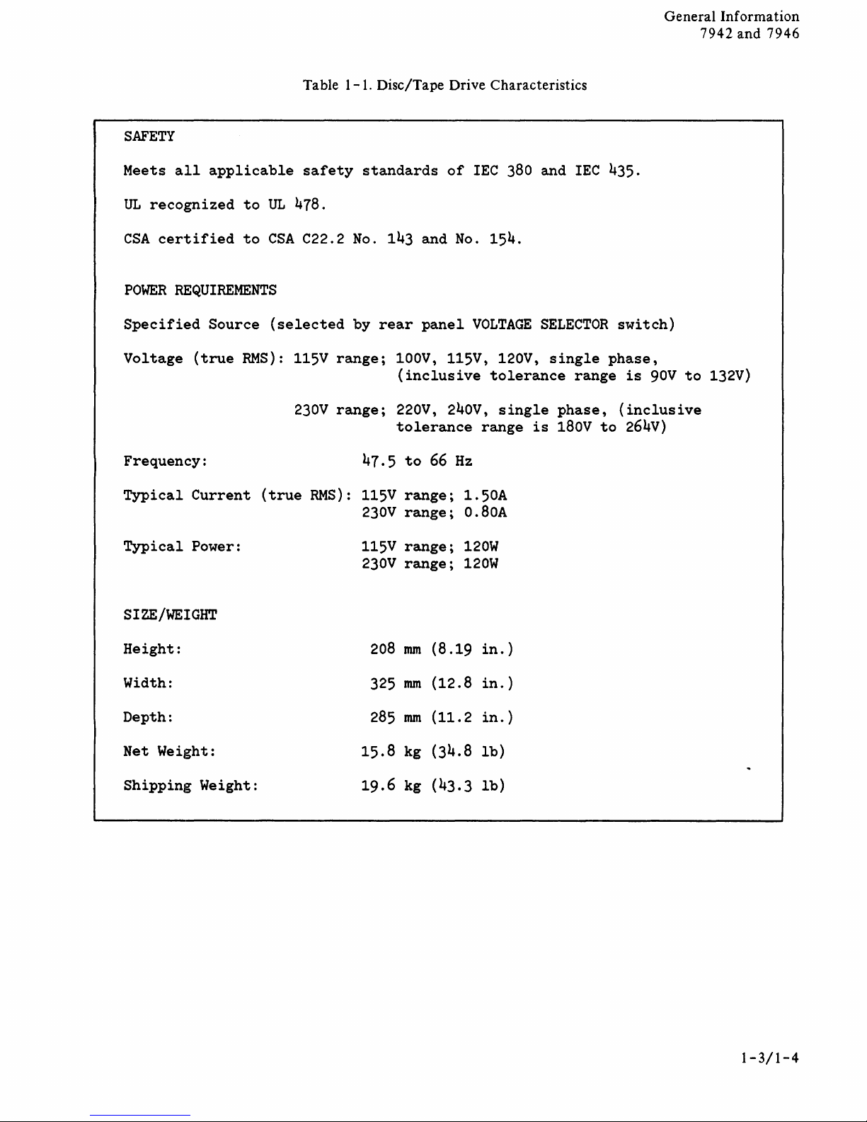
CHARACTERISTICS
Characteristics of the
physical dimensions
listed in table
disc/tape
and
power requirements, are
1-1,
drive, including
Disc/Tape Drive
Characteristics. Detailed specifications for
c/tape
ments, are listed
Requirements
no.
the
Service
tics of
drive, including environmental
in
Site
for
5955-3456.
disc/tape
Manual
the
tape drive.
Disc/Tape
This publication
drive. Refer to
for specifications
Drives Manual,
Environmental
is
supplied
the
H P 9
and
characteris-
the
dis-
require-
part
with
I44A
1-2
Page 17
SAFETY
Table
1-1.
Disc/Tape Drive Characteristics
General Information
7942 and 7946
Meets
UL
CSA
POWER
Specified
Voltage
Frequency:
Typical
Typical
all
recognized
certified
REQUIREMENTS
(true
Current
Power:
applicable
to
UL
to
CSA
Source
(selected
RMS):
(true
safety
47B.
C22.2
115V
230V
RMS):
standards
No.
by
range;
range;
47.5
115V
230V
115V
230V
of
IEC
143 and
rear
100V, 115V, 120V,
(inclusive
220V, 240v,
tolerance
to
range;
range;
range;
range;
panel
66
No.
154.
VOLTAGE
tolerance
range
Hz
1.50A
O.BOA
120W
120W
3BO
single
is
and
IEC
435.
SELECTOR
single
phase,
1Bov
phase,
range
to
switch)
is
90V
(inclusive
264V)
to
132V)
SIZE/WEIGHT
Height:
Width:
Depth:
Net Weight:
Shipping
Weight:
20B
325
2B5
15.B
19.6
nun
nun
nun
kg
kg
(B.19
(12.B
(11.2
(34.B
(43.3
in.
in.
in.
lb)
lb)
)
)
)
1-3/1-4
Page 18

Page 19
CHANNEL
INTERFACE
-
QIJ
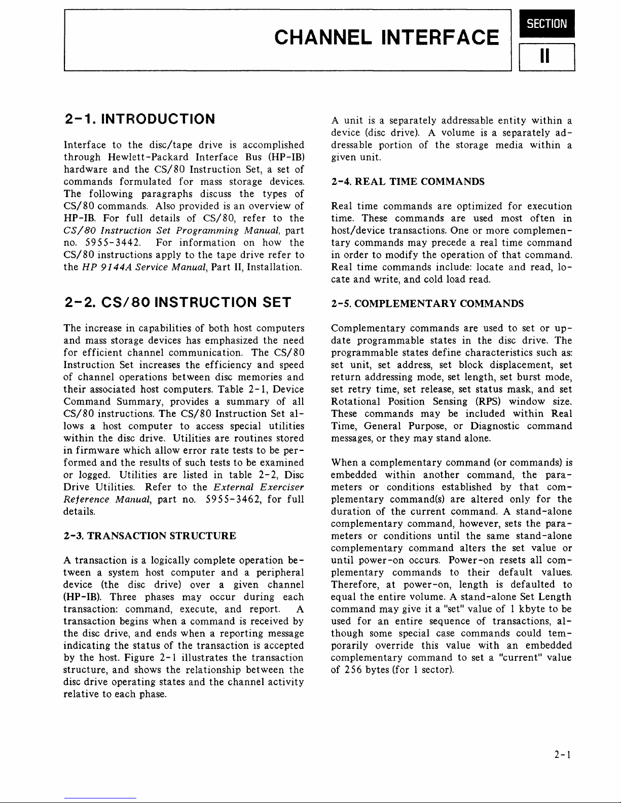
2-1.
Interface
through
hardware
commands
The following paragraphs discuss
CS/
HP-IB.
CS/80
no.
CS/80
the
2-2.
The
and
for
Instruction
of
their
Command
CS/80
lows a host
within
in
formed
or
Drive Utilities.
Reference
details.
2-3.
A
tween
device (the disc drive) over a given
(HP-IB).
transaction: command, execute,
transaction
the
indicating
by
structure,
disc drive
relative
INTR~ODUCTION
to
the
disc/tape
Hewlett-Packard
and
the
CS/80
formulated
80 commands. Also provided
For
full details of
Instruction
5955-3442.
instructions apply
H P
9144A
CS/,BO
increase in capabilities of
mass storage devices has emphasized
efficient
Set increases
channel
firmware
logged. Utilities
TRANSACTION
transaction
disc drive,
the
operations between disc memories
associated host computers. Table
Summary, provides a
instructions.
the
disc drive. Utilities
which
and
the
Manual,
a system host
Three
begins
the
host. Figure 2 - 1 ill
and
operating
to
each phase.
Set
For
Service
INSTRUCTION
channel
The
computer
allow
results of such tests
are
Refer
part
is
a logically complete
phases
when a command
and
ends
status
of
shows
the
states and
drive
is
Interface
Instruction
for
mass storage devices.
is
CS/80,
Programming
information
to
the
tape
Manual,
communication.
to
to
STRUCTURE
computer
when a reporting
the
Part
both
the
efficiency
summary
CS/8 0 Instruction
access special utilities
are
error
rate
listed in
the
no.
may
transaction
ustra
relationship between
table
External
5955-
and a peripheral
occur
and
tes
the
the
channel
accomplished
Bus (HP-IB)
Set, a set of
the
an
overview
refer
Manual,
on how
drive
II,
Installation.
host computers
The
2-1,
routines stored
tests
to
be examined
3462,
operation
during
report. A
is
received by
transaction
types of
to
part
refer
SET
the
need
CS/80
and
speed
Device
of
Set
to
be
per-
2-2,
Disc
Exerciser
for
channel
each
message
is
accepted
activity
of
the
the
to
and
all
al-
full
be-
the
A
unit
is
a separately addressable
device (disc drive). A volume
dressable portion of
given unit.
2-4.
REAL
Real
time
time. These commands
host/
device transactions. One
tary
commands
in
order
time
Real
cate
and
2-5.
COMPLEMENTARY
Complementary
date
programmable states in
programmable states
set unit, set address, set block displacement, set
return
retry
set
Rotational
These commands
Time,
messages,
When a complementary
embedded
meters
plementary
duration
complementary
meters or conditions
complementary
until
power-on
plementary
Therefore,
equal
command
used
for
though
porarily override this value
complementary
of 256 bytes (for 1 sector).
TIME
commands
to
modify
commands include: locate
write,
and
addressing mode, set length, set
time, set release, set
Position Sensing (RPS) window size.
General
or
they
within
or
conditions established by
command(s)
of
the
commands to
at
power-on,
the
entire
may
give
an
entire
some special case commands could
the
storage media
COMMANDS
are
optimized
are
may
precede a real
the
operation
cold load read.
COMMANDS
commands
define
may
Purpose, or Diagnostic
may
another
current
command, however, sets
command
occurs.
volume. A
it a lise
sequence of transactions,
command
are
characteristics such
be included
stand
alone.
command (or commands)
command,
are
command. A
until
the
alters
Power-on
length
stand-alone
til
to set a
entity
is a separately
for
used most
or
more com pie
time
of
that
and
used to set
the
disc drive.
burst
status
altered
their
value
same
the
resets all
default
is
of 1 kbyte
with
"current"
mask,
within
only
stand-alone
stand
set value
defaulted
an
within
within
execution
often
men
command
command.
read,
or
upThe
mode,
and
Real
command
the
para-
that
com-
for
the
para-
-alone
com-
values.
Set
Length
to
tem-
embedded
value
ad-
in
lo-
as:
set
is
the
or
to
be
al-
a
a
-
2-1
Page 20
Channel
7942
and
In
terf
7946
ace
Table 2
-1.
Device
Command
Summary
LOCA
FUNCTION:
OPCODE:
FORMAT:
LOCA
FUNCTION:
OPCODE:
FORMAT:
LOCA
FUNCTION:
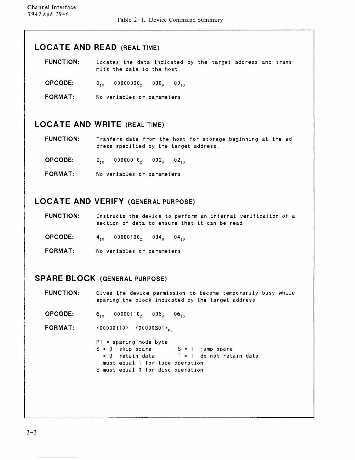
TE
AND READ (REAL TIME)
Locates
mits
No
variables
TE
AND
TE
AND VERIFY (GENERAL PURPOSE)
WRITE
Tranfers
dress
No
variables
Instructs
section
the
the
data
(REAL TIME)
data
specified
the
of
data
data
to
the
or
parameters
from
by
or
parameters
device
to
indicated
the
the
ensure
host.
host
target
to
perform
by
that
the
for
storage
address.
an
it
target
internal
can be
address
beginning
verification
read.
and
at
trans-
the
ad-
of a
OPCODE:
FORMAT:
SPARE
FUNCTION:
OPCODE:
FORMAT:
BLOCK
No
variables
(GENERAL PURPOSE)
Gives
sparing
<00000110>
P1 = sparing
S = 0
T = 0
T must
S must
the
skip
retain
equal 1 for
equal 0 for
or
device
the
block
<OOOOOSOT>Pl
mode
spare
data
parameters
permission
indicated
byte
tape
disc
to
by
the
S = 1
T = 1
operation
operation
become
target
jump
do
not
temporarily
address.
spare
retain
data
busy
while
2-2
Page 21
Table
2-1.
Device
Command
Summary
(continued)
Channel
7942
In
and
terf
7946
ace
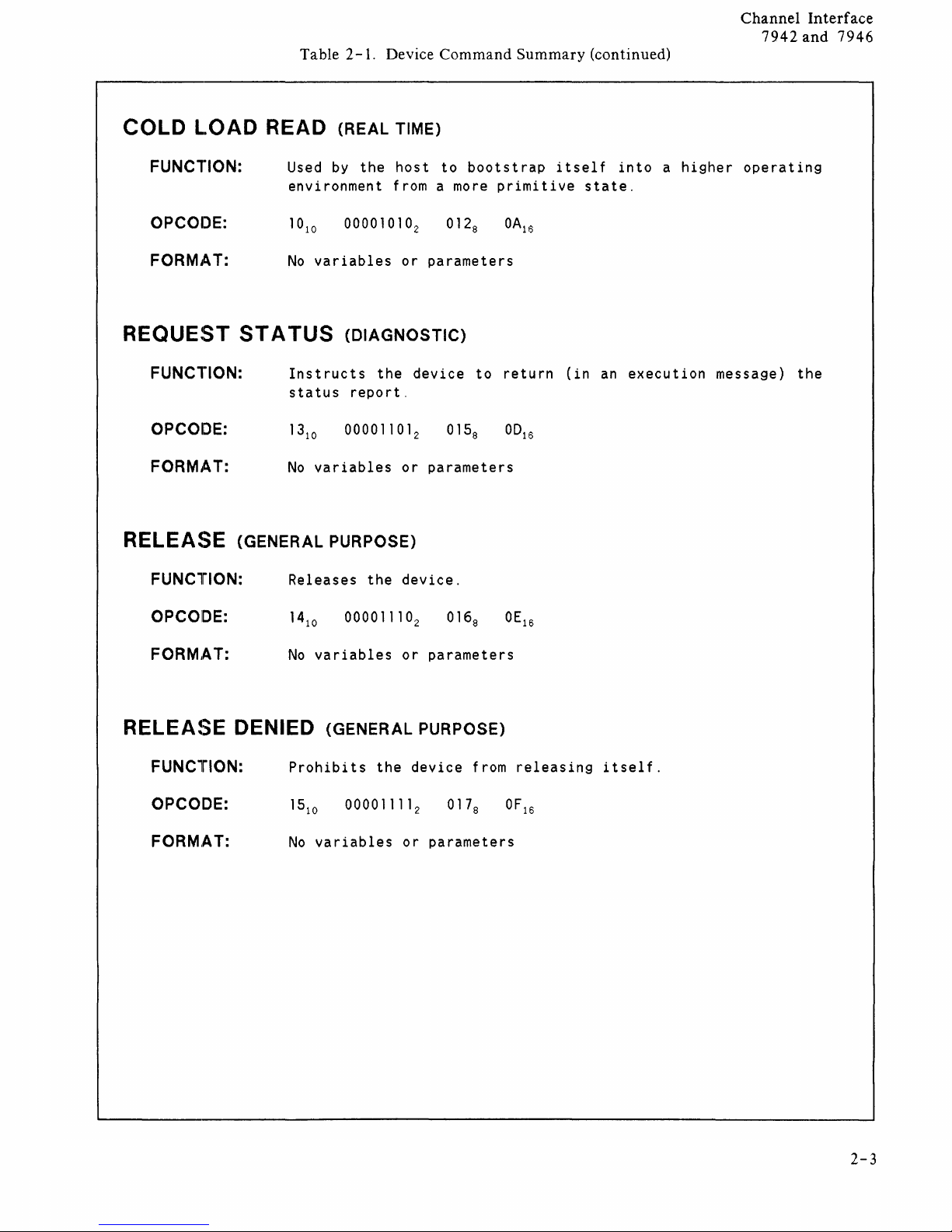
COLD
L.OAD READ (REAL TIME)
FUNCTION:
OPCOIJE:
FORMAT:
REQUEST
FUNCTION:
OPCOIDE:
FORMj~T:
RELEASE
FUNCTION:
Used
by
the
host
environment from a more
No
variables
ST A TUS
(DIAGNOSTIC)
Instructs
status
No
(GENERAL PURPOSE)
report.
variables
Releases
the
the
or
or
device.
to
bootstrap
parameters
device
parameters
primitive
to
return
itself
state.
(in
into a higher
an
execution
operating
message)
the
OPCOIDE:
FORMAT:
RELEASE
FUNCTION:
OPCODE:
FORM,AT:
No
variables
or
parameters
DENIED (GENERAL PURPOSE)
Prohibits
No
variables
the
device
or
parameters
from
releasing
itself.
2-3
Page 22
Channel
7942
and
Interface
7946
Table 2
-1.
Device
Command
Summary
(continued)
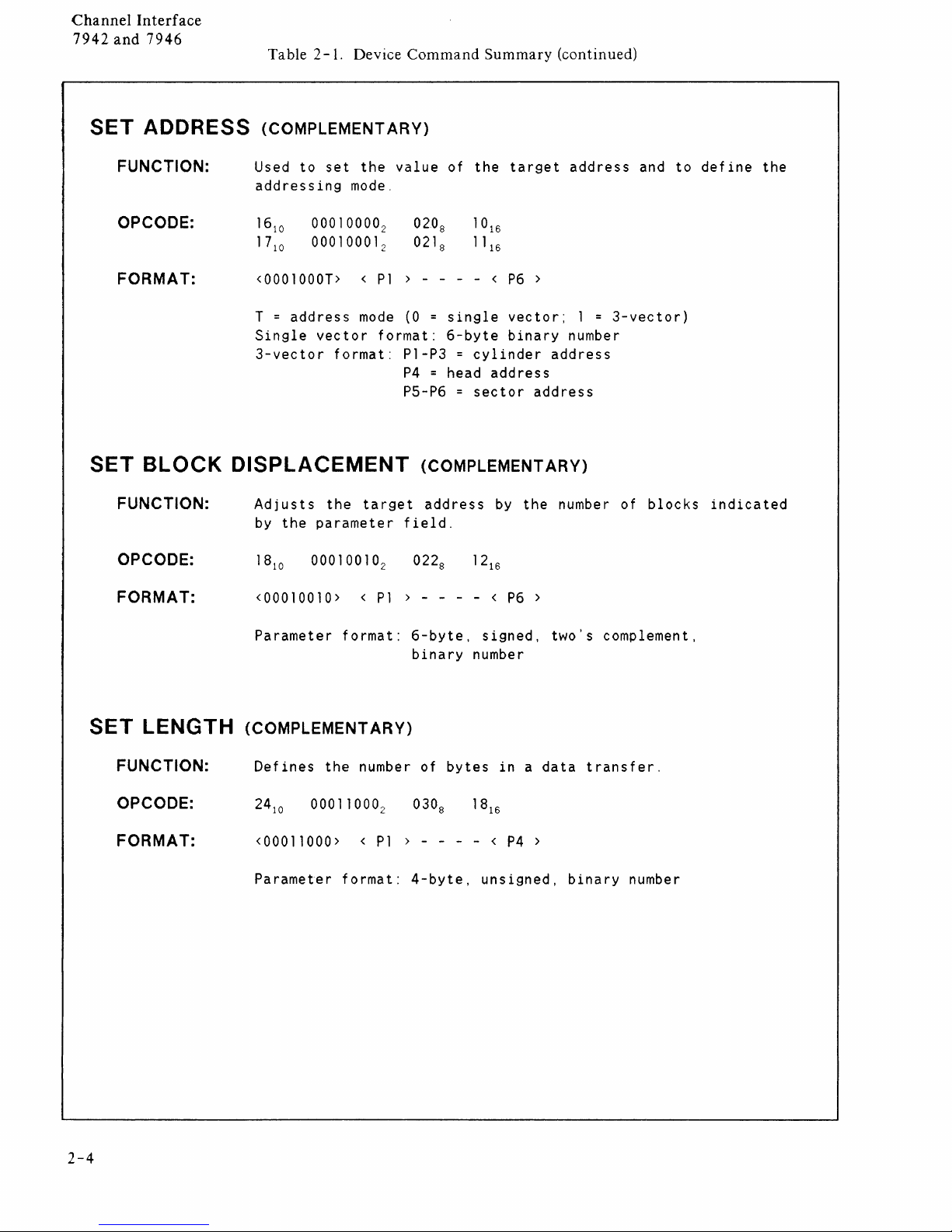
SET
SET
ADDRESS (COMPLEMENT
FUNCTION:
OPCODE:
FORMAT:
BLOCK
FUNCTION:
OPCODE:
ARY)
Used
to
set
the
value
addressing
16
10
17
10
<0001000T> <
T
=
address
Single
3-vector
mode.
00010000
00010001
mode
vector
format:
2
2
P1
format:
DISPLACEMENT
Adjusts
by
the
the
target
parameter
of
the
target
020
8
021
8
> - - - - <
(0 = single
6-byte
P1-P3 =
P4
= head
P5-P6 =
(COMPLEMENTARY)
address
P6
vector;
binary
cylinder
address
sector
by
the
>
address
field.
address
1 =
number
address
number of
and
3-vector)
blocks
to
define
the
indicated
FORMAT:
SET
LENGTH (COMPLEMENTARY)
FUNCTION:
OPCODE:
FORMAT:
<00010010> <
Parameter
Defines
format:
the
<00011000> <
Parameter
format:
P1
> - - - - <
6-byte,
binary
number of
P1
) - - - - <
4-byte,
number
bytes
P6
>
signed,
in a data
P4
>
unsigned,
two's
binary
complement,
transfer.
number
2-4
Page 23
Table
2-1.
Device
Command
Summary
(continued)
Channel
7942
In
and
terf
7946
ace
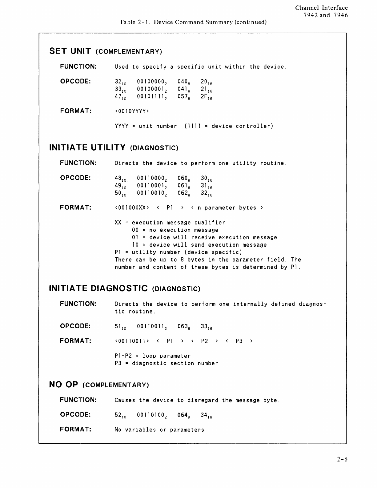
SET
UNIT (COMPLEMENTARY)
FUNCTION:
OPCODE:
FORM,AT:
INITIA l"E
FUNCTION:
OPCODE:
FORMAT:
Used
32
10
33
10
47
10
<0010YYYY>
YYYY = unit
UTILITY
Directs
48
10
49
10
5010
<001000XX>
xx
Pl =
There can be
number and
to
specify a specific
00100000
00100001
00101111
2
2
2
number (1111
(DIAGNOSTIC)
the
device
00110000
00110001
00110010
2
2
2
<
=
execution
00 = no
execution
01 = device
10 = device
utility
number
up
content
040
8
041
8
057
8
to
perform
060
8
061
8
062
8
>
Pl
< n
message
will
receive
will
send
(device
to 8 bytes
of
these
unit
20
16
21
16
2F
16
device
30
16
31
16
32
16
parameter
qualifier
message
execution
specific)
in
bytes
within
controller)
one
utility
bytes
execution
message
the
parameter
is
determined
the
device.
routine.
>
message
field.
by
The
Pl.
INITIA l"E
FUNCTION:
DIAGNOSTIC
Directs
tic
the
routine.
OPCODE:
FORM,AT:
<00110011> < Pl <
Pl-P2
=
loop
P3 = diagnostic
NO OP (COMPLEMENTARY)
FUNCTION:
OPCODE:
FORM,AT:
Causes
No
the
variables
(DIAGNOSTIC)
device
to
perform
parameter
section
device
to
or
parameters
disregard
P2
number
one
<
the
internally
P3
>
message
defined
byte.
diagnos-
2-5
Page 24
Channel
7942
and
In
terf
7946
ace
Table
2-1.
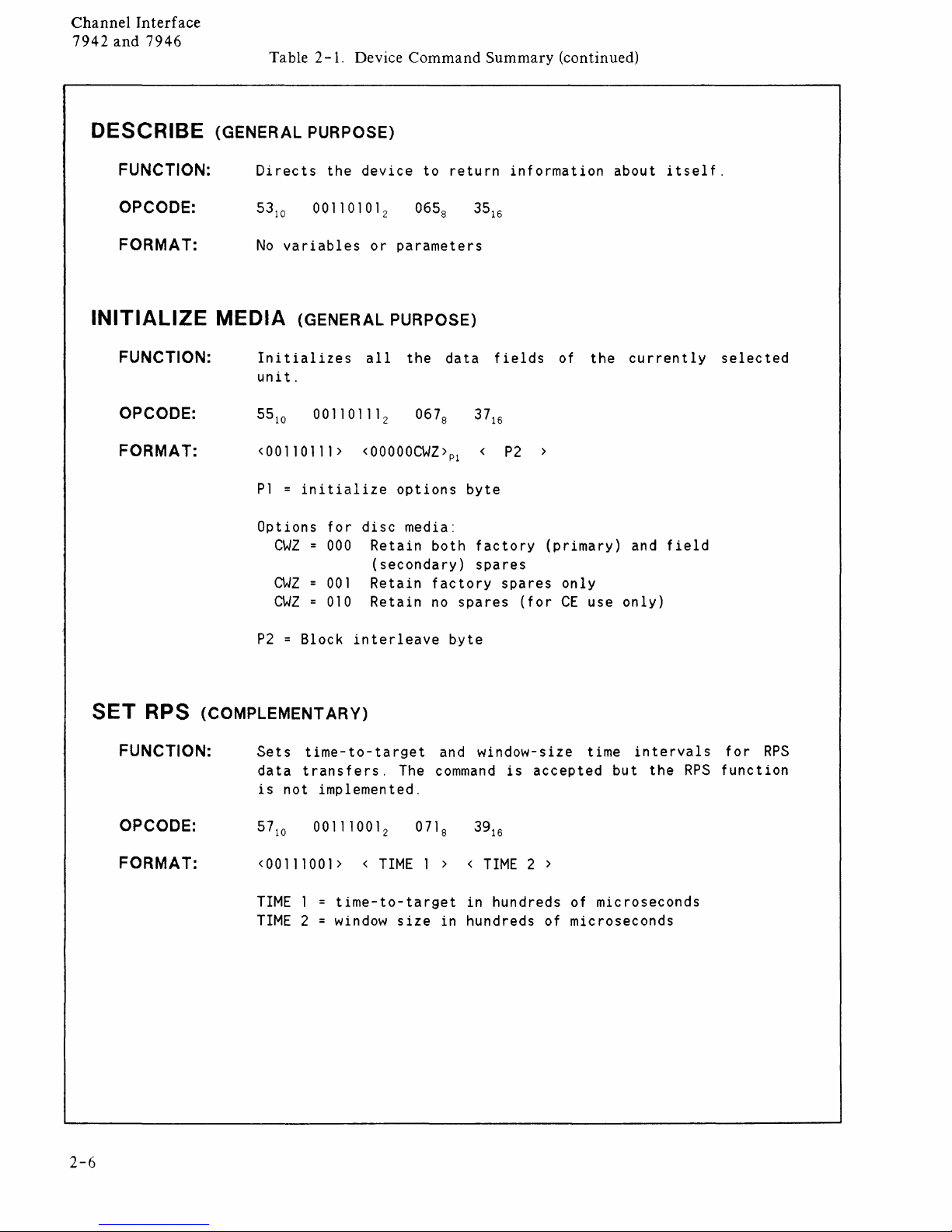
DESCRIBE (GENERAL PURPOSE)
Device
Command
Summary
(continued)
FUNCTION:
OPCODE:
FORMAT:
INITIALIZE
FUNCTION:
OPCODE:
FORMAT:
Directs
No
the
variables
device
or
parameters
to
return
MEDIA (GENERAL PURPOSE)
Initializes
unit.
<00110111>
P1 = initialize
Options
CWZ
CWZ
CWZ
all
the
<OOOOOCWZ>Pl < P2
options
for
disc
media:
000
Retain
both
(secondary)
001
010
Retain
Retain
factory
no
data
byte
spares
information
fields
factory
spares
spares
(f
of
(primary)
only
0 r
CE
use
the
about
currently
and
only)
itself.
selected
field
SET
RPS (COMPLEMENTARY)
FUNCTION:
OPCODE:
FORMAT:
P2
= Block
Sets
data
is
time-to-target
transfers.
not implemented.
interleave
<00111001> <
TIME
TIME
time-to-target
1
2
window
The
TIME
size
byte
and
command
1>
in
window-size
is
accepted
<
TIME
2 >
in
hundreds of
hundreds of
time
intervals
but
the
microseconds
microseconds
RPS
for
RPS
function
2-6
Page 25
Table
2-1.
Device
Command
Summary
(continued)
Channel
7942
In
and
terf
7946
ace
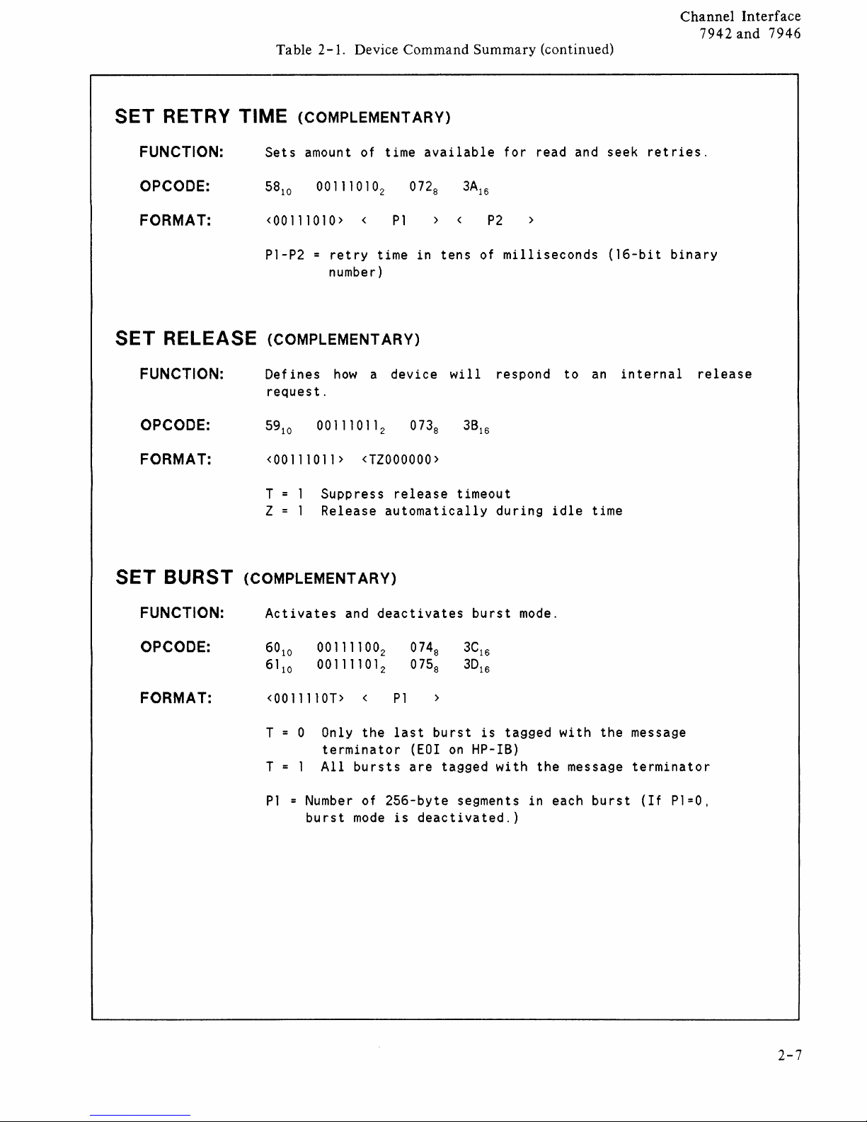
SET
SET
RETRY TIME
FUNCTION:
OPCODE:
FORMAT:
RE~LEASE
FUNCTION:
OPCODE:
FORMAT:
(COMPLEMENTARY)
Sets
amount of time
<00111010> <
P1-P2 =
retry
time
available
P1
in
number)
(COMPLEMENTARY)
Def
ines
how
a dev
ice
request.
<00111011> <T2000000>
T
2
Suppress
Release
release
automatically
tens
wi
11
timeout
for
read and
>
P2
of
milliseconds
respond
during
to
idle
seek
(16-bit
an
time
in
te
retries.
binary
rnal
release
SET
BlJRST
FUNCTION:
OPCODE:
FORMAT:
(COMPLEMENTARY)
Activates
60
10
61
10
and
00111100
00111101
deactivates
2
2
<0011110T> <
T 0 Only
the
terminator
T
P1 = Number
All
burst
bursts
of
mode
256-byte
074
8
075
8
>
P1
last
burst
(EOI
are
tagged
is
deactivated.)
burst
3C
16
3D
16
is
on
HP-IB)
segments
mode.
tagged
with
the
in
with
message
each
the
burst
message
terminator
(If
P1=0,
2-7
Page 26
Channel
7942
and
Interface
7946
Table
2-1.
Device Command"Summary (continued)
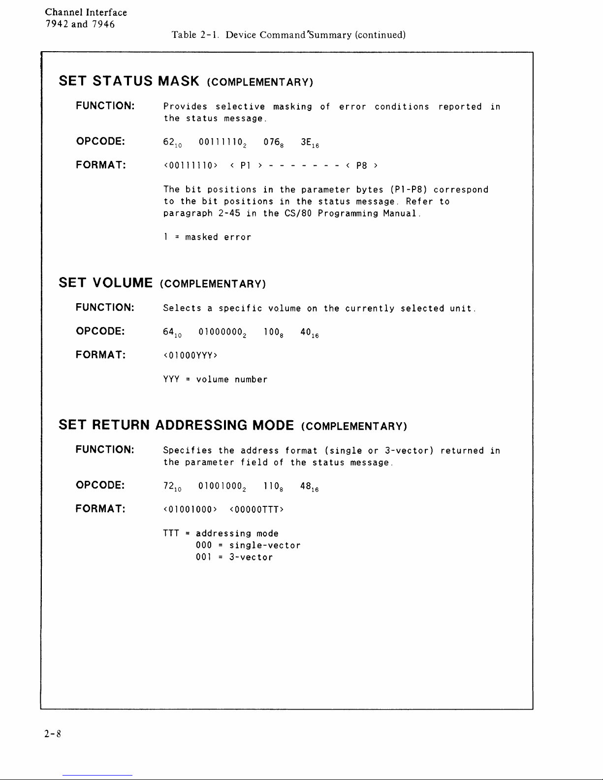
SET
SET
ST A TUS
FUNCTION:
OPCODE:
FORMAT:
VOLUME
FUNCTION:
OPCODE:
FORMAT:
MASK
Provides
the
<00111110> <
The
to
paragraph
1
= masked
(COMPLEMENTARY)
(COMPLEMENTARY)
selective
status
message.
Pl
bit
positions
the
bit
positions
2-45
in
error
Selects a specific
64
10
01000000
2
<01000YYY>
masking of
> - - - - - - - <
in
the
parameter
in
the
the
CS/80 Programming Manual.
volume
on
error
status
the
P8
bytes
message.
currently
conditions
>
(Pl-P8)
Refer
selected
reported
correspond
to
unit.
in
SET
RETURN ADDRESSING MODE
FUNCTION:
OPCODE:
FORMAT:
YYY
= volume number
Specifies
the
parameter
72
10
<01001000>
the
01001000
<OOOOOTTT>
address
field
TTT = addressing
000
single-vector
001 = 3-vector
2
mode
(COMPLEMENTARY)
format
of
the
(single
status
or
3-vector)
message.
returned
in
2-8
Page 27
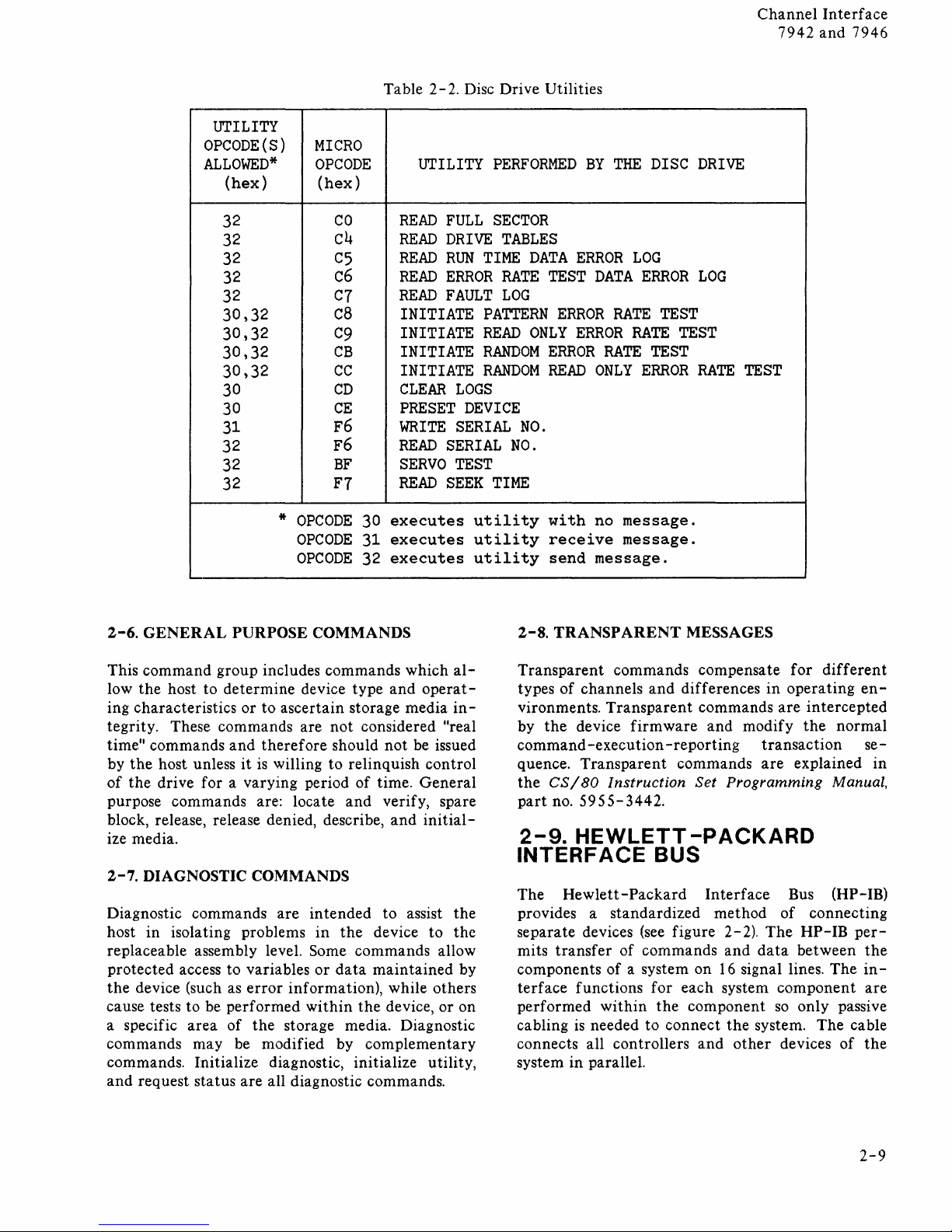
UTILITY
OPCODE(S)
ALLOWED*
(hex)
32
32
32
32
32
30,32
30,32
30,32
30,32
30
30
31
32
32
32
MICRO
OPCODE
(hex)
CO
c4
C5
c6
C7
c8
C9
CB
CC
CD
CE
F6
F6
BF
F7
Table
2-2.
UTILITY
READ
READ
READ
READ
READ
INITIATE
INITIATE
INITIATE
INITIATE
CLEAR
PRESET
WRITE
READ
SERVO
READ
Disc Drive Utilities
PERFORMED
FULL
DRIVE
RUN
ERROR
FAULT
SECTOR
TABLES
TIME
DATA
RATE
LOG
TEST
PATTERN
READ
ONLY
RANDOM
RANDOM
ERROR
READ
LOGS
DEVICE
SERIAL
SERIAL
NO.
NO.
TEST
SEEK
TIME
BY
ERROR
DATA
ERROR
ERROR
RATE
ONLY
THE
LOG
ERROR
RATE
RATE
TEST
ERROR
DISC
TEST
TEST
DRIVE
LOG
RATE
Channel
7942
TEST
Interface
and
7946
*
OPCODE
OPCODE
OPCODE
2-6.
GENERAL
This
command
low
the
host to
ing characteristics
tegrity. These commands are
commands
time"
the
by
of
purpose commands are: locate
block, release, release denied, describe,
ize media.
2-7.
Diagnostic commands
host
replaceable assembly level. Some commands allow
protected access to variables
the
cause tests to be
a specific
commands
commands. Initialize diagnostic, initialize utility,
and
host unless
the
drive for a varying period
DIAGNOSTIC COMMANDS
in
isolating problems
device (such as
request status
PURPOSE COMMANDS
group includes commands
area
may
determine
or
and
it
error
performed
of
the
be modified by
are
device
to
ascertain storage media
not
therefore
is
willing
are
storage media. Diagnostic
all diagnostic commands.
should
to
in
tended
in
or
information), while others
within
the
data
executes
30
executes
31
executes
32
which
type
and
considered "real
not
relinquish control
of
time.
and
verify, spare
and
to assist
device to
maintained
the
device,
complementary
al-
operat-
in-
be issued
General
initial-
the
the
by
or
on
utility
utility
utility
with
receive
send
2-8.
TRANSPARENT
Transparent
types
of
channels
vironments.
by
the
device
command
quence.
the
part
2-9.
-execution
Transparent
CS/80
no.
5955-3442.
HEWLETT-PACKARD
INTERFACE
The
Hewlett-Packard
provides a
separate
mits
components
terface
performed
cabling
connects all controllers
system in parallel.
devices (see figure 2-2).
transfer
functions
is
needed to
no
message.
message.
message.
MESSAGES
commands compensate
and
differences
Transparent
firmware
Instruction
commands
and
-reporting
commands
Set
Programming
BUS
Interface
standardized
of commands
of
a system on
for
within
the
connect
method
and
16
each system
component
the
and
other
for
in
operating
are
intercepted
modify
signal lines.
system.
the
transaction
are
explained
Bus (HP-IB)
of
connecting
The
HP-IB
data
between
component
so
only passive
devices
different
en-
normal
se-
Manual,
per-
the
The
in-
are
The
cable
of
the
in
2-9
Page 28
Channel
7942
and 7946
Interface
TRANSACTION
PHASE
CO~MAND
Q
(0
EXECUTION
G
@
REPORTING
(1)
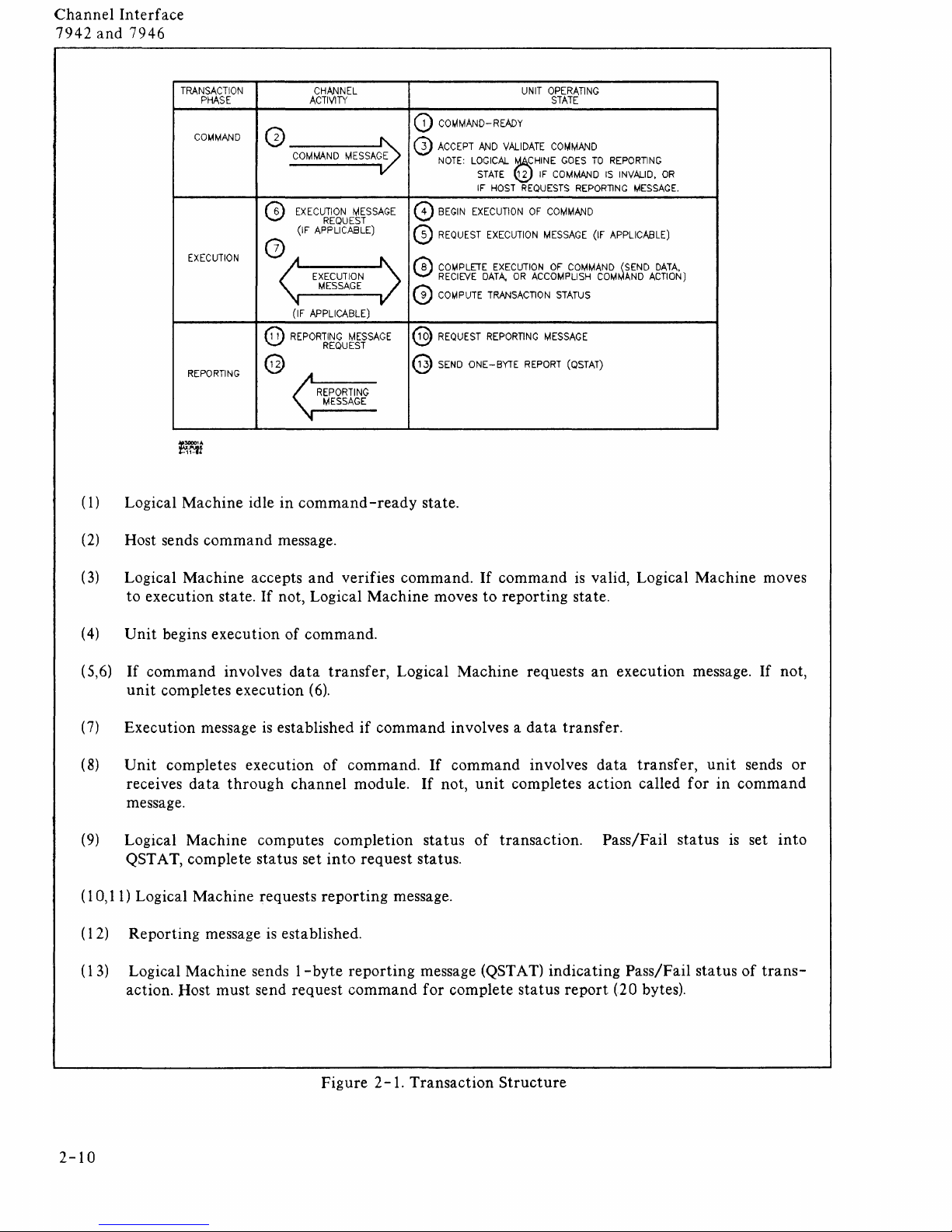
Logical Machine idle in command
(2)
Host sends command message.
@
CHANNEL
ACTIVITY
COMMAND
EXECUTION
REQUEST
(IF
APPLICABLE)
A
EXECUTION
MESSAGE
'I
(IF
APPLICABLE)
REPORTING
REQUEST
.A
REPORTING
MESSAGE
'It
MESSAGE
MESSAGE
MESSAGE
-ready
CD
COMMAND-READY
@
ACCEPT
AND
NOTE:
o
BEGIN
@
REQUEST
(1)
CO~PLETE
RECIEVE
G
COMPUTE
@
REQUEST
@
SEND
VALIDATE
LOGICAL
STATE
IF
HOST
EXECUTION
EXECUTION
EXECUTION
DATA.
TRANSACTION
REPORTING
ONE-BYTE
state.
UNIT
~HINE
12
IF
REQUESTS
OF
MESSAGE
OR
ACCOMPLISH
MESSAGE
REPORT
OPERATING
STATE
COMMAND
GOES
TO
COMMAND
REPORllNG
COMMAND
(IF
OF
COMMAND
STATUS
(QSTAT)
REPORTING
IS
INVALID.
MESSAGE.
APPLICABLE)
~SEND
COM
AND
ACTION)
OR
DATA.
(3)
Logical Machine accepts
to
execution state.
(4)
Unit
begins execution of command.
(5,6)
If
command involves
unit
completes execution
(7)
Execution message
(8)
Unit
completes execution
receives
data
If
through
and
verifies command. If command
not, Logical Machine moves
data
transfer,
(6).
is
established
if
of
command.
channel module. If not,
message.
(9)
Logical Machine computes completion status
QST AT, complete status set
(10,11) Logical Machine requests
(12) Reporting message
(1
3)
Logical Machine sends 1 - byte reporting message
is
action. Host must send request
into
reporting
established.
command
request status.
to
reporting state.
Logical Machine requests
command involves a
If
command involves
unit
of
data
completes action called for
transaction. Pass/Fail status IS set
message.
(QST A T)
for complete status
is
valid, Logical Machine moves
an
execution message.
transfer.
data
transfer,
unit
in
indicating Pass/Fail status
report
(20 bytes).
If
not,
sends
or
command
into
of
trans-
2-10
Figure 2
-1.
Transaction
Structure
Page 29
Channel
7942
In
and
terf
7946
ace
DATA
A (8
SIGNAL~NES)
<....,..
..
..-
---
..
..-
..
--
..
..-
..
..-.
..
..-.
.......
\/
TALK.LlSTEN
AND
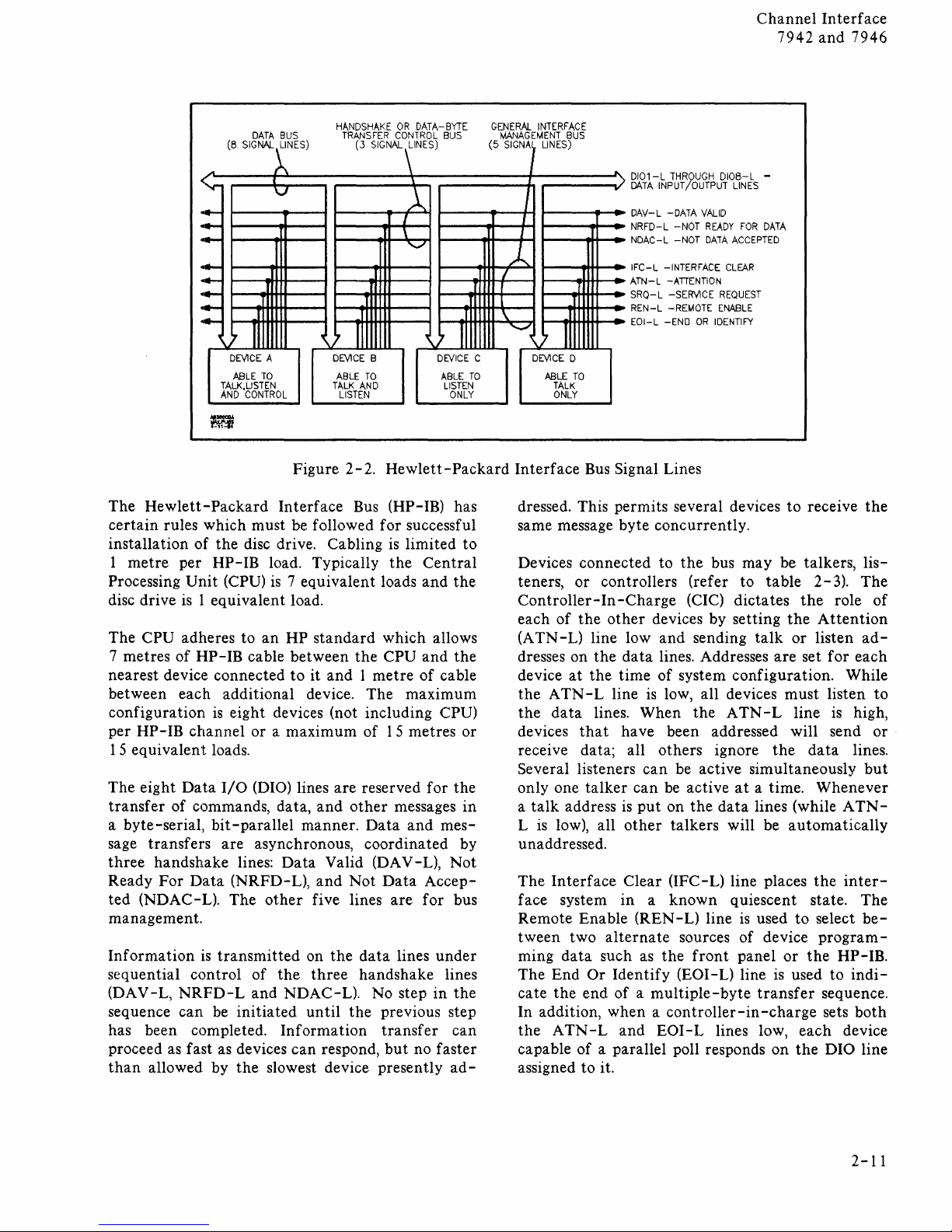
The
Hewlett-Packard
certain
installation of
1
Processing
disc drive
The
7 metres
rules which must be followed for successful
the
metre
per
HP-
Unit
(CPU)
is
1 equivalent load.
CPU adheres to an HP
of
HP-IB
I
V
J J J
II
DEViCE
A
ABLE
TO
CONTROL
disc drive. Cabling
IB
load. Typically
is
cable between
nearest device connected
BUS
HANDSHAKE
TRANSFER
~
>'
DEVICE
ABLE
TALK
LISTEN
Figure 2-2.
Interface
7 equivalent loads
standard
to
it
and 1 metre
OR
DATA-BYTE
CONTROL
(3
SIGNAL~INES)
fI
8
TO
AND
~
I
\
'-./
~
BUS
>'
II
DEVICE
ABLE
LISTEN
ONLY
Hewlett-Packard
Bus (HP-IB) has
is
limited to
the
Central
and
the
which allows
the
CPU
and
the
of
cable
between each additional device. The maximum
is
configuration
per
HP-IB
eight devices (not including CPU)
channel
or a maximum of 15 metres
or
15 equivalent loads.
The eight
transfer
a byte-serial,
sage transfers
three
Ready For
ted (NDAC-L). The
Data
I/O
(DIO) lines
of commands, data,
bit-parallel
are
asynchronous, coordinated by
handshake lines:
Data
(NRFD-L),
other
are
and
manner.
Data
Valid (DAV -L),
and
five lines
reserved for
other
messages
Data
and
Not
Data
are
the
in
mes-
Not
Accep-
for bus
management.
Information
sequential control
(DAV-L,
sequence can be
has been completed.
proceed as fast
than
allowed by
is
transmitted
NRFD-L
as
on
the
data
of
the
and
NDAC-L). No step
initiated
three
until
handshake lines
the
Information
devices can respond,
the
slowest device presently
lines
under
in
the
previous step
transfer
but
can
no faster
ad-
GENERAL
(5
.~
C
TO
INTERFACE
MANAGEMENT
SIGNA,
1
I
~
I
r
\ J
~
Interface
I
DEVICE
BUS
LINES)
'1
II
D
ABLE
TO
TALK
ONLY
Bus Signal Lines
...
DI01-L
THROUGH
DATA
INPUT
...
DAV-L -DATA
NRFD-L -NOT
NDAC-L -NOT
IFC-L
-INTERFACE
ATN-L
-ATIENTION
SRQ-L -SERViCE
REN-L
-REMOTE
EOI-L -END
jOUTPUT
VALID
READY
DATA
ENABLE
OR
IDENTIFY
DI08-L
LINES
ACCEPTED
CLEAR
REQUEST
dressed. This permits several devices
same message byte concurrently.
Devices connected to
teners,
Controllereach
(A
dresses on
device
the A TN
the
devices
of
TN -L)
at
data
or
controllers (refer to
In
-Charge
the
other
line low
the
data
the
time
-L line
lines. When
that
have been addressed will send
the
bus may be talkers,
(CIC) dictates
devices by setting
and
sending
lines. Addresses
of
system configuration. While
is
low, all devices
the A TN
receive data; all others ignore
can
Several listeners
only one
talk
a
is
L
talker
address
low), all
is
other
be active simultaneously
can
be active
pu t on
the
at
data
talkers will be
unaddressed.
Interface
The
face system
Remote Enable (REN tween two
ming
data
The End
cate
the
In addition,
the
ATN-L
capable
Clear (IFC-L) line places
in a known
alternate
such
as
the
Or
Identify
end
of a multiple-byte
sources of device
(EOI-L) line
quiescent state.
L)
line
front
when a controller-in-charge
and
EOI-L
of
a parallel poll responds on
lines low,
assigned to it.
-
FOR
DATA
to
receive
table 2-3).
the
role
the
Attention
talk
or
listen
are
set for each
must
listen
- L line
the
is
data
a time. Whenever
lines (while A
automatically
the
inter-
is
used
to
select
program-
panel
or
is
used to
transfer
the
HP-IB.
sequence.
sets
each
device
the
DIO line
the
lis-
The
of
ad-
to
high,
or
lines.
but
TN
The
be-
indi-
both
-
2-11
Page 30
Channel
7942
and
In
terf
7946
ace
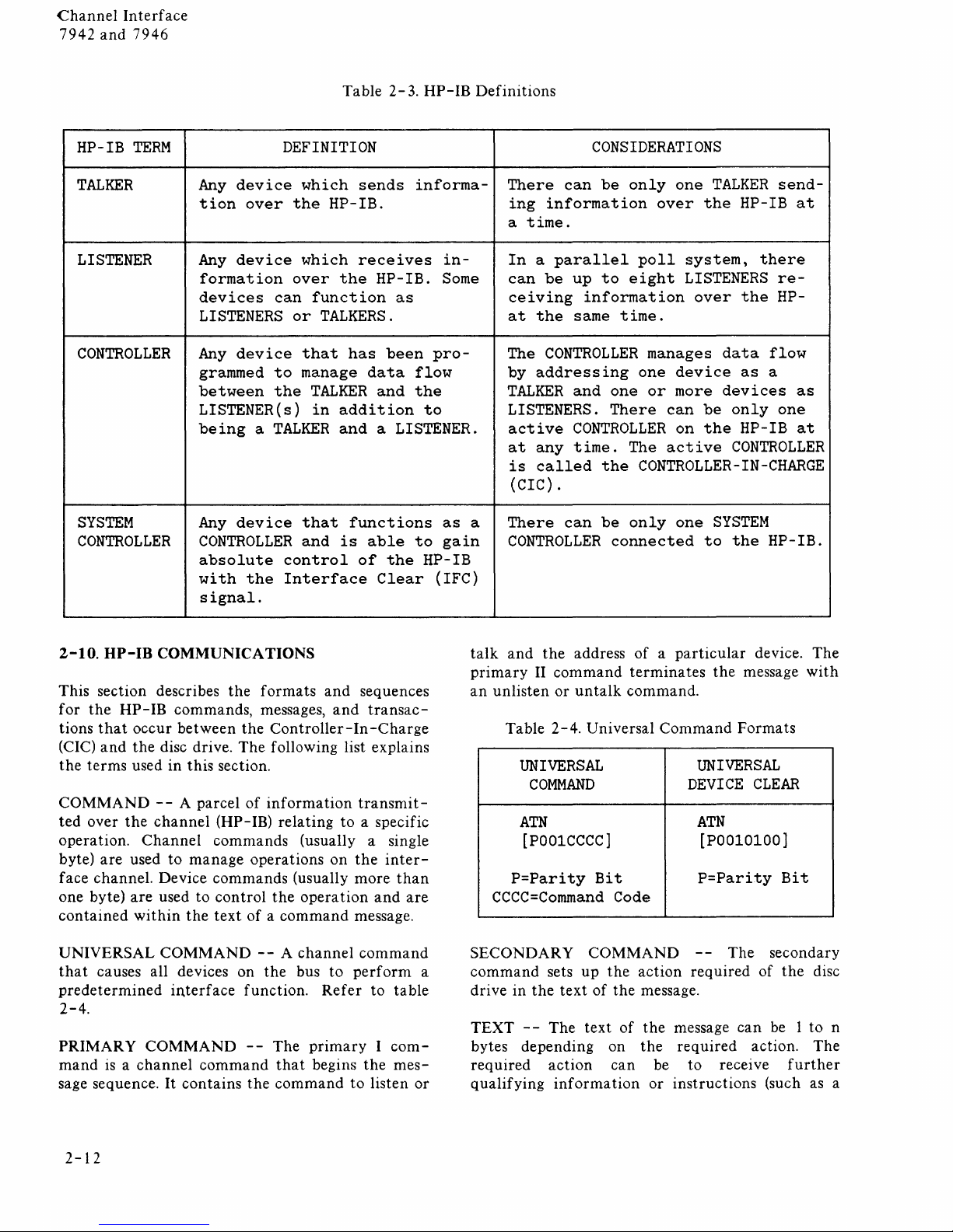
HP-IB
TERM
TALKER
LISTENER
CONTROLLER
SYSTEM
CONTROLLER
DEFINITION
Any
device
tion
Any
over
device
formation
devices
LISTENERS
Any
device
grammed
between
LISTENER(s)
the
over
can
or
to
the
which
which
function
TALKERS.
that
manage
TALKER
in
being a TALKER
Any
device
CONTROLLER
absolute
with
the
that
and
control
Interface
signal.
Table 2-3.
sends
HP-IB
informa-
HP-IB.
receives
the
HP-IB.
in-
Some
as
has
been
data
and
addition
proflow
the
to
and a LISTENER.
functions
is
able
of
the
Clear
as
to
gain
HP-IB
(IFC)
Definitions
There
ing
a
time.
In a parallel
can
ceiving
at
the
The
by
addressing
TALKER
LISTENERS.
active
at
any
is
called
(CIC) .
There
a
CONTROLLER
CONSIDERATIONS
can
be
only
information
poll
be
up
to
eight
information
same
time.
CONTROLLER
one
and
one
There
CONTROLLER
time.
can
The
the
CONTROLLER-IN-CHARGE
be
only
connected
one
over
the
system,
LISTENERS
over
manages
device
or
more
can
be
on
the
active
one
to
TALKER
send-
HP-IB
there
re-
the
HP-
data
flow
as
a
devices
only
one
HP-IB
CONTROLLER
SYSTEM
the
HP-IB.
at
as
at
2-10.
UP-IB
This section describes
for
the
tions
that
(CIC)
and
the
terms
COMMAND --A
ted
over
operation.
byte)
are
face
channel.
one byte)
contained
UNIVERSAL
that
causes all devices on
predetermined
2-4.
PRIMARY
mand
is a channel
sage sequence.
COMMUNICATIONS
HP -
IB
commands, messages,
occur
between
the
disc drive.
used
in
this
parcel
the
channel
Channel
used
to
manage
Device
are
used to
within
the
COMMAND --A
interface
COMMAND
command
It
contains
the
formats
the
Controller-In
The
following list explains
section.
of
information
(HP-
IB)
relating
commands
operations
commands
control
text
the
of a command
the
function.
--
The
that
the
command
and
sequences
and
transac-
-Charge
transmit-
to
a specific
(usually a single
on
the
inter-
(usually
operation
channel
bus
more
than
and
message.
command
to
perform
Refer
pnmary I com-
begins
to
to
the
listen
table
mes-
are
or
talk
and
the
address
primary
an
II
unlisten
Table
command
or
un
2-4.
Universal
UNIVERSAL
COMMAND
ATN
[POO1CCCC]
P=Parity
CCCC=Command
SECONDARY
a
command
drive
TEXT --The
bytes
required
qualifying
sets
in
the
text
depending
action
information
up
text
of a particular
terminates
talk
command.
Command
Bit
Code
COMMAND
the
action
of
the
message.
of
the
on
the
can
be
or
the
message
Formats
UNIVERSAL
DEVICE
ATN
[POO101OO]
P=Parity
--
The
required
message
required
to
instructions
can
receive
device.
CLEAR
Bit
secondary
of
the
be 1
action.
further
{such as a
The
with
disc
to
The
n
2-12
Page 31

Channel In
7942
and
terf
7946
ace
device command), to receive
or
read
status data,
or
write
data, to send
to
perform a specific
operation such as a CLEAR.
MESSAGE --A unique sequence
text
bytes
which
(for example, CIC
transmitted
the
communication
and
over the
link
the
disc drive) remains
of
command
channel
between
the
broken.
COMMAND 1vtESSAGE --A single message
taining
device
programmable parameter,
be executed by
all
and
the
information
initiate
an
required
an
operation, set
or
set up
execution message.
to
an
operation
address a
EXECUTION MESSAGE --A single message
taining all
an
operation previously set
the
information
required
up
by a command
to
carry
sage.
TRANSACTION - - A complete process
tion carried
tions
are
message,
and
a reporting message.
2-11.
CHANNEL
out
completed
and
some
over
the
channel. Some
with
only a
require
a command, execution,
MANAGEMENT
command/report
or
transac-
and
during
devices
un-
con-
up
to
con-
out
mes-
opera-
Disable (PPD) are
internal
controller. PPE occurs when
the
service from
and
occurs whenever
CIC. PPD
the
states
of
the
the
disc drive requires
is
the
opposite
disc drive
is
disc drive
state
active (for
example, busy executing a command) or idle. A
the
Parallel Poll Response (PPR) from
the
will occur if
EOI-L
2-13.
and
if
UNIVERSAL DEVICE CLEAR. A
sal command
devices on
a
interface
inf
orma tion stored in
places
the
function. Universal Device Clear erases
the
disc drive
universal device clear
CIC asserts
the
disc drive
is
a channel command
HP-IB
to
perform a pre-determined
the
in
a known reset state. The
format
both
is
in
the
disc drive con troller
is
disc drive
A TN -
PPE state.
that
causes all
shown
Land
univer-
and
in
table
2-4.
2-14.
MESSAGE
Each message contains
er
to table 2 -
(reJ
- -
Primary I Command
STRUCTURE
the
following components
5).
(unidirectional from CIC to device)
- - Secondary
Command
(unidirectional from CIC to device)
The following techniques
the
manage
HP-IB: Parallel Poll
are
used by
Device Clear.
2-12.
parallel poll on
EOI
vice can
PARALLEL
-L
simultaneously. Each device requiring
then
POLL. The CIC conducts a
the
HP -
IB
by asserting A
respond by asserting
corresponding to its address. The CIC
es
only
the
device
one device requires service,
device
with
first. Parallel Poll Enable (PPE)
requiring
the
highest priority (lowest address)
service.
the
CIC addresses
and
the
CIC to
and
Universal
TN -Land
the
DIO line
then
address-
If
more
Parallel Poll
ser-
than
the
- - Text (bidirectional)
II
- - Primary
Command
(unidirectional from CIC to device)
TN
-L
The CIC asserts A
dary
commands to distinguish
during
formation. The disc drive decodes
contained
in
both
the
primary
primary
them
and
from
the
information
I and secondary
commands to prepare for action specified
text.
secon-
text
in
in-
the
2-13
Page 32

Channel
7942
and
Interface
7946
PRIMARY
I
[ATN]
[ONE
BYTE]
--Unidirectional
*CIC
to
device
--Begins
message
*Addresses
device
LISTEN
to
or
TALK
*Universal
HEADER
[ATN]
[ONE
--Unidirectional
*CIC
--Set
further
Table 2-5.
SECONDARY
BYTE]
to
device
up
device
action
HP-IB
DEVICE
--Bidirectional
--Qualifying
to
for
--Write
--Read
--Status
Message
TEXT
COMMAND
device
data
data
data
Structure
OR
instructions
to
device
to
CIC
to
CIC
DATA
TRAILER
PRIMARY
II
[ATN]
[ONE
BYTE]
--Unidirectional
*CIC
to
device
--Terminates
message
--Unaddresses
device
*Unlisten
*Untalk
2-14
Page 33

THEORY OF OPERATION
3-1.
The Hewlett-·Packard 7942 and 7946 Disc/Tape
Drives are medium performance, random access,
data storage devices designed for use with small
and medium sized computer
consists of a 24-megabyte disc drive and a tape
drive combined in a single desktop cabinet to form
an
sists of
combined in a similar manner.
The disc/tape
consists of three separate units: a host dependent
controller (HDC),
the tape drive,
structure,
storage devices (disc drive and tape drive) are
solidated in the HOC and drive dependent tasks are
performed by two separate device dependent
trollers (DOC's), one located
and one in
tions of the HOC include: host interface, direct
memory access (DMA), error correction, control for
DOC execution of commands, status monitoring,
and diagnostic self
dependent tasks performed
select, sector formatting, seek control,
ter/separator:1 and drive control and status.
The
over the
and with
ture's
IB
completely independent
bus with assoc'iated
bus.
The assemblies located in the drive cabinet include
a
ly (peA), two device dependent controller
disc drive meGhanism, a tape drive mechanism, and
a power supply. The two
power supply assembly are positioned side-by-side
at
mechanisms are mounted above. The
located above the two drive mechanisms. The
INTRODUCTION
systems_
integrated disc/tape drive. The HP 7946
aSS-megabyte
data
Unit
the
common functions of the two mass
th,e
tape drive unit. The common
HOC communicates with
Hewlett-Packard
the
DOC's over the mass storage
data/control
contains
host dependent controller printed
the bottom of the cabinet and
an
8-bit
disc drive and a tape drive
storage functional
Unit
2;
the
disc drive,
1.
See
figure 3 -
in
-test
routines. Typical device
by
a DOC include head
Interface
interface bus (DC-IB). The
read/write
8-bit
5-bit
control/status
DOC PCA's and the
The HP 7942
Unit
the disc drive unit,
the
host computer
Bus
data
bus, and a
control/status
-circuit
the
HOC PCA
con-
structure
0;
and
3.
In this
con-
con-
func-
format-
(HP-IB)
struc-
DC-
data
address
assemb-
PC
A's,
two drive
is
PCA's, power supply, and drive mechanisms are
terconnected by a number of cable assemblies.
Circuits in
face integrated circuit
firmware in
array
gate
The
applicable to
Typical
seek control circuits,
serializer / deserializer, and DMA circuitry.
The disc drive mechanism consists of a sealed
head-disc module with spindle and motor, discs,
read/write
ing mechanism (actuator), and an
tem. Also located in the disc drive mechanism are
circuits for reading and writing,
control, status control, and spindle speed control.
The tape drive assembly consists
mechanism with
motor, and a capstan drive motor. Mounted
the
mechanism are a servo PCA
PCA. The servo PCA contains control
the
tape drive capstan drive motor and head
per motor. The
preamplifier circuitry and a write
The power supply assembly
contained, PCA -mounted, switch
supply.
Included in
nostic self
tions of the drive and indicate faults on a
numerical display which
ing in
panel indicators driven by
a
controllers show
drive and the tape drive. The drive has dedicated
maintenance tracks on which are logged
of some of the self tests. The in ternal diagnostics
permit off
drive, and power supply. This furnishes a quick and
easy means of
and subtest level. An additional troubleshooting
the
HOC PCA include
(IC),
ROM, RAM, a custom-designed DMA
IC,
and self
DOC PCA's contain
their
DOC circuitry includes drive select logic,
heads, a rotary voice-coil head position-
the
host dependent controller are
-test
the
rear panel of the cabinet. Also,
-line
fault
-test
controls and display.
drive-related
associated drive mechanisms.
read/write
read/write
routines which exercise key
is
visible
the
operating status
testing of the HOC, disc drive, tape
isolation
an
HP-IB
a microprocessor,
formatter
air
heads, a head
and a read/write
PCA includes read
is
comprised
-mode
through
the
device dependent
to
the
/separator,
filtration
actuator
of
a tape drive
circuitry
current
of a self-
of
the
unit, assembly,
in-
inter-
circuitry
sys-
servo
-stepper
within
for
step-
driver.
dc power
diag-
func-
2-digit
an
open-
front
the
disc
results
3-1
Page 34

Theory
7942 and 7946
of
Opera tion
aid
is
provided by a
which links
utility
external
HP-IB
with
Refer
for a detailed description of
of operation.
• Tape Drive Service Manual, Section III,
programs to service
the
to
Troubleshooting.
3-2.
The
disc drive assemblies
random access, mass storage devices
with
use
formatted
semblies
respectively. In this section,
both
specified.
The
and
diameter
is
of
prerecorded servo
precise positioning of
The disc drive employs a
control
dent
troller
common functions
(disc drive, tape drive) are consolidated in
and
DDC.
host interface, direct memory access (DMA),
correction, control for DDC execution
mands, status monitoring,
routines. Drive dependent tasks
DDC involve
necessary to read or
opera tions incl ude serializa
modified frequency
coding/decoding, DMA handshaking,
detection.
disc drive assemblies, unless otherwise
head-disc
uses two
used for each disc surface.
the
lowest disc in
controller (HDC) and a device
(DDC). See figure 3 -
drive dependent tasks
The
the
exerciser
channel
system host.
the
and
following source in this publication
DISC DRIVE
small
and
storage capacities
are
24 megabytes
module in
or
nonremovable discs. One
structure
common functions of
manipulation
CS/8 0 External
drive
internal
-trained
can
also be used to check
the
interaction
the
diagnostics
tape
Exerciser
personnel. The
of
the
drive theory
INTRODUCTION
are
medium
medium sized computers. The
of
and
"disc drive" refers to
the
disc drive
four
130-millimetre
The
the
stack
contains continuous
data
which
the
which consists
of
typical mass storage devices
write
is
read/write
peripheral
4.
In this
are
and
of
data
tion/
modulation
performance,
intended
the
disc drive
S S megabytes,
is
(S.12-inch)
read/write
bottom
used to ensure
heads.
of
a host
dependent
performed
the
diagnostic self
performed
the
on
the
deserializa tion,
surface
mass storage
structure,
the
HDC include:
of
data
disc. These
(MFM)
and
and
drive
sealed
head
depen-
con-
HDC
by
error
com-
-test
by
stream
error
the
for
as-
the
the
the
the
en-
Associated
which contains a sealed
electronic control
circuits operate in
in
the
nals, position and
over
tional speed, and
tions.
The
mass storage device, such as a
fitted
minimum
connection of
up device.
The HDC communicates
over
and
ture's
DC-IB
a completely independent
bus
bus.
assembly via the
ST-S06
electrical
established by
ted as
The
disc drive consists
printed
dent
and
power supply assembly A4. Disc drive
ly A 1
side by side
A2
and
The
cable assemblies.
Circui
include
a microprocessor,
mabIe read
read/write
DMA gate
Device dependent
disc
IC. Disc drive assembly A 1 contains a sealed
disc module
(R/W)
driver
with
the DDC
and
conjunction
DDC to
the
HDC
with
the
with
Data/Control
contains
with
The
Interface.
an
-circuit
controller PCA - A2, disc drive assembly
and
AS are
four
ts on
an
controller
heads, a servo head, read
IC's, a servo
interpret
maintain
desired track,
perform
is
capable
a suitable DOC. This facilitates,
of
additional electronic
the
cartridge
Hewlett-Packard
the
ODC's over
an
8-bit
associated
DDC communicates
data
and
mechanical
the
Shugart
industry-wide
assembly PCA - A
power supply assembly
at
the
bottom
mounted
assemblies
the
host de penden t con
HP-IB
-only
array
interface
firmware
memory (EPROM),
memory (RAM), a custom -designed
IC,
controller
IC
and
with
spindle motor, discs,
is
a disc drive assembly
head-disc
read/write
and
generate
the
maintain
read
of
interfacing
cartridge
tape
with
Interface
the
mass storage
Interface
read/write
8-bit
6-bit
The
self
control/status
with
and
control
ST-506
standard
Corporation
standard.
of
host
dependent
of
the
horizontally above them.
are
connected
integrated
in erasable
-test
switches
PCA - A2 includes a
a phase-locked loop (PLL)
preamplifier
module
circuits. These
with
the
circuitry
control
read/write
precise disc
and
write
with
a second
tape
circuitry,
drive
as a
the
host
computer
Bus (HP-IB)
Bus (DC-IB).
data
control/status
the
disc drive
lines
Interface
for
disc drives
and
con
5,
device
A4
are
mounted
cabinet
preamplifier/write
together
troller
circuit
random
and
IC, a
and
PCA - AS
program-
read/write
and
sigheads
rota-
opera-
drive,
with
the
back-
struc-
The
bus,
and
data
address
of
the
is
an
adap-
troller
depen-
AI,
assemb-
PCA's
by
(IC),
-access
display.
head-
rotary
a
3-2
Page 35

Theory
7942
of
Operation
and
7946
voice-coil head positioning mechanism (actuator),
and
air
filtration
drive assembly A
programmed
channel,
spindle speed control. Power supply assembly
a self
supplies de voltages
the
A typical operation of
read,
command
HP-IB
preted
roprocessor executes code
Ec)
and
EPROM directs
EPROM to execute commands necessary for
mand
controls
and
The
the
tuator
its microprocessor
which
track,
tion
track,
read.
the
the
read/write
disc cQntroller
and
HnC
roprocessor via
data
a time, for errors. Errors
using
IC.
fer
via
IC.
The
amount
sembled, checked for errors,
sent to
is
and
-contained
disc drive.
is
performed
from
interface
by
the
firmware
management
completion.
the
the
nne.
nnc
is
disc controller IC
servo
represents
the
nDC
on
the
the
disc
The
MFM
disc passes
read
preamplifier/write
packed in to bytes. These bytes
RAM, previously assigned by
is
being assembled,
information
The
Hnc
of
data
nMA
complete,
gate
operation
of
the
components. Also located in disc
I
are
a microprocessor
logic
array
(PLA), a
circuits
Hnc
disc drive assembly via
given
control
data
data
exec
from
data
host computer. When
the
for
actuator
switch
the
in EPROM to
the
verifies
track.
rotates
-encoded
from
channel
IC.
the
array
-mode
and a power-on
the
as follows: The locate
host
computer
IC,
is
stored in RAM,
microprocessor. The
from
functions.
nnc
0 (disc drive) code
The
nnc
the
seek
argument,
in
the
in disc drive assembly A 1 via
and
PLA
with a stream
the
seek offset
the
locality
If
the
until
serial
the
read/write
to
Here
the
nMA
supplied by
firmware
the
continues
has been successfully read,
nnc
gate
it
is
are
RAM to
Ie
and
gives ending
read/write
servo
power supply
reset signal to
disc drive, locate
enters
the
executive
carry
out
The
exec code
0 EPROM
the
nnc
to
argument.
from
head
is
on
the
correct
data
driver
the
nnc
MFM
checked, one sector
coordinates
buffered
data
are
the
array
corrected
the
disc
the
host
the
HP-IB
until
the
the
unit
control
and
the
and
Hnc
its
firmware
nC-IB
which
drive
of
informa-
the
stream
head
IC
PLL IC
is
sent to
HnC
IC.
in
the
controller
the
computer
interface
requested
in
RAM,
data
status
and
data
and
A4
which
and
read
HnC
inter-
mic-
(EX-
control
com-
bus
causes
the
ac-
pulses
Once
on
proper
sector
from
through
and
the
and
decoded
the
mic-
As
the
Hnc
trans-
as-
and
transfer
is
in
in
is
at
to
the
exec code. The ending status
computer.
and
write
A locate
cate
and
read operation previously described except
the
for
set up
same. However,
from
verify
start
controller
drive
once
position.
Included in
test routines
disc drive
hexadecimal display which
opening in
front
nnc
drive. The disc drive has dedicated
tracks
are
testing
power supply. This furnishes a
means of
subtest level.
provided by a
links
programs
External
HP-IB
drive
The
first
more detailed
description of
provided.
In
sheets of
each sheet
lower
numerals
text, for example:
The
diagram
and
"Source" column
direction in which
and
head positioning operations
the
HP-IB
operation. This
moving
read/write
it
panel
PCA-Al
logged. The
the
with
disc drive
at
order
mnemonics used in
digital signals
from
IC serializer
is
determined
the
which
and
the
FAULT/ON
where
of
the
fault
disc drive
to
service
Exerciser
channel
the
a basic block
to
facilitate
the
functional
is
identified
right -hand
are
and
accompanying
operation
the
data
interface
is
the
RAM
and
channel
that
Hnc
firmware
exercise key functions of
indicate
rear
panel
shows
the
internal
HnC,
isolation to
An
system host.
circuitry
functional
the
printed
the
results of some
nnc,
additional
CS/80
internal
-trained
can
and
the
diagram
disc recording
text
corner
in boxed characters
III.
are
defined
of
table
the
is
done to allow
the
of
LINE
diagnostics
External
also be used to check
is
block
by a large
3-1,
is
sent to
is
similar to
user
data
accepted
IC prior to
through
formatter,
as quickly
head
are
diagnostic
faults
is
visible
the
disc drive. Also, a
indicator
operating
of
permit
disc drive assembly,
quick
the
unit, assembly,
troubleshooting aid
Exerciser
diagnostics
personnel. The
interaction
discussed in this section,
level
block
diagram
references
diagram
numeral
of
the
the
functional
text
to
in
table 3
the
assembly
the
the
flows.
are
into
the
the
seek
the
data
the
nnc
and
the
as
possible
is
in the
on a
status of
and
format
identify
proper
l-digit
through
driven
maintenance
the
self tests
off
and
and
CS/
of
the
then
level. A
is
to
the
(figure
page. These
in
analog
-1.
host
lo-
The
the
RAM
and
to
disc
disc
self-
the
an
by
the
-line
and
easy
and
is
which
utility
8 0
the
disc
at
also
three
3-
5),
in
the
the
block
In
the
where
a
3-3
Page 36

Theory
of
Operation
7942 and 7946
the
signal originates
numeral
block
Most of
"-
L"
identifying
diagram
the
or "-H"
mnemonics listed in table 3 - 1 have
suffixes. These suffixes
where
is
listed,
the
the
followed by a boxed
sheet of
assembly
the
is
shown.
identify
functional
low or active high logic signals, respectively.
nals
without
such suffixes are usually bus
or
signals.
active
Sig-
analog
at
the
inner
diameter
of
the
disc to
permit
locations. Also, duplicating
at
two locations reduces
data
due to recording medium failure. The 968
data
tracks
This provides
ers.
The
are
the
1 7 spare
tracks containing
used
user
hard
(ID) and
read/write
for
with
tracks
errors.
outer
diameter
testing
the
service
the
possibility
reading
and
968 addressable
are
used
for
writing
(OD)
at
these
information
of
loss
of
data.
cylind-
sparing
out
In addition, Section IV, Service
tains system cabling
diagrams for
3-3.
The two plated
A 1 provide
read/write
the
DISC
three
head. The
disc drive.
FORMAT
metal
and
discs
data
surfaces, each
fourth
Information,
signal
in
disc drive assembly
surface
is
servo head for prerecorded servo data.
discs in
data
the
surfaces
55
megabyte version provide seven
and
one servo surface. See figure
III
Each
data
surface
circles called tracks. See figure
side
diameter
test/maintenance
tracks, 485 da
test/maintenance
The two self
testing reading
tain
service information, including
fault
logs,
and
3-1.
The self
is
of
track,
divided
the
ta
disc
483
data
tracks,
into
987 concentric
3-1.
From
there
are: 1 self -
tracks, 1 7 spare
and
track.
test/maintenance
and
writing. These
tracks
tracks
are
run
a spare table directory. See figure
-test/maintenance
tracks
con-
distribution
with
one
used
with
a
The
four
the
out-
1 self -
used
for
also
con-
-time
are
logs,
located
Each
data
sequentially-numbered
tors. Figure 3 - 2 shows
32
data
track
sectors, each
IS organized
blocks of
the
track
having
256 bytes
in
to smaller
data
called
format,
of
formation. The beginning of each sector
tified by a
which
cylinder
lowed by
ID field
two-byte
first
byte
pattern.
A 1
the
ID address
da
ta
address mark.
summary
A
user available
7945
is
Sector
Track
Head
7941
7945
prewritten
contains
and
the
and
the
head information. This ID field
data
field.
the
data
characters
in
both
address marks
This
is
mark
of
the
data
identification
physical sector address plus
The
beginning
field
is
called address marks. The
followed by
and
an
F 8
recording
tracks
capacity
in
the
provided below.
Oat a
Bytes
Per
256
8,129
7,929,856
23,789,568
55,508,992
Sectors
Pe
r
30,976
92,928
216,832
32
of
flagged by
is
a hexadecimal
an
FE
pattern
pattern
provided by
HP 7941
Tracks
Pe
r
968
2,904
6,776
based
data
is
(I
D)
both
and
Heads
Pe
sec-
on
in-
iden-
field
is
fol-
the
unique
for
for
the
HP
r
3
7
3-4
Page 37

Theory
7942
of
Operation
and
7946
INNER
8~METER
NUMBER
TRACKS
OF
1
SELF
+B-3
D~TA
SPARE
485
D~TA
1
SELF
LANDING
AAD
INNER
GUARD
TEST
TEST
BAND
+MAlNTENANCE
17
+MAINTENANCE
•
•
ZONE
.SELF
SECTOR
ADDRESS
0
1-5
6-10
11-15
16-18
19-20
21-22
23-31
FILE-FSJEFl2A
TEST
Figure
AND
NAiNTENANCE
OUTER
DIAN
ETER
PRODUCT
RUN
TIME
ERRO~
RffE
TEST
ERT
FAULT
LOG
SPARE
TABLE
SELF
TEST
LOC~TION
SELF
TEST
LOC~TION
NOT
USED
3-1.
Disc Recording
(00)
NO.
LOG
LOG
TRACK
CONTENTS:
INNE,
OI,AMETER
SERIAL
RUN
TINE
ERRO~
TEST
ERT
F~ULT
LOG
SPARE
SELF
TEST
LOCATlON
SELF
TEST
LOCATlON
NOT
USED
Format
10)
NO.
LOG
~TE
LOG
T,6BLE
3-5
Page 38

Theory
7942
and
of
Operation
7946
L
iD
I
I
I
SYNC
GAP'
24X 14X
4E
FlLE-fSJEF11A
3-4.
Host
terface
dependent
HDC
of
functions
are
dependent
separation,
Host
is via
and
Interface
Host
• A host
•
• A
•
HOC
dependent
between
controller
is also capable
a second mass storage device.)
required
consolidated
tasks (servo control, read, write,
data
dependent
the
Hewlett-Packard
with
the
Bus (DC-IB).
dependent
interface
Direct
data
tion,
Firmware
memory
random
examination
and
DDC commands
• Self
-test
~----
DO
A1
ID
ADDRESS
MARK
PCA-AS
controller
the
for
in
generation, etc.) to
controller
DDC's via
controller
access
speed
for
diagnostic capabilities.
PCA-A5
host
computer
(DDC)
of
interfacing
the
the
HDC leaving
the
functions
via
the
access (DMA) capability.
memory
for
matching
a microprocessor
and
monitor
Figure
provides
and
the
of
the
disc drive. (The
with
The
two
mass storage devices
the
the
interface
Interface
HDC's
with
Bus (HP-IB)
Data/Control
include:
HP-IB.
(RAM)
integrity,
buffer
error
between devices.
to
status.
REPEATED
3-2.
Track
an
in-
device
the
DDC
common
device
data
DDC's.
the
host
for
correc-
execute
32
TIMES.
(325
BYTES)
DATA
ADDRESS
MARK
Recording
The
firmware
•
THERE
Format
in
IS
NO
the
ments. One segment
tem
(EXEC EPROM)
location (including
RAM),
tion
terface
comprise
and
between
firmware.
the
the
the
the
passing
DDC
The
control
storage devices (DDC
processor
firmware
is
shared between
and
the
executive
ing, each receiving
proximately
takes care
function
firmware
The
DDC's
0.5 millisecond.
of
its own task,
the
host
or
is
included
communicate
DC-IB. This bus contains
data
bus
with
appropriate
associated 6 completely
with
associated strobes.
The
following
description of
cuitry,
diagram, sheet
scription
_
sheet
bit
control/status
independent
paragraphs
the
as shown on
_ .
of
the
mnemonics used
host
the
Lf
GAP3 GAP4
ECC
4
BYTES
GAP 3 ON
HDC consists
is
the
executive
which
DMA
of
firmware
remaining
firmware
0
and
the
microprocessor
device has requested. Self
in
each
with
8-bit
provide a more
dependent
disc drive
Refer
3X 24X 16X
OD
4E
NOMINAL
LAST
SECTOR.
of
three
operating
controls resource
gate
array
messages
and
and
the
two
for
the
DDC
1).
The
the
two
sets
firmware
Each
set
by
of
performing
of
the
three
the
HDC
an
8-bit
control/status
read/write
strobes
address bus,
read/write
controller
functional
to table
in
3-1
the
text
4E
IC
informa-
host
segments
two
micro-
of
timeshar-
for
firmware
whatever
segments.
over
data
detailed
for a de-
and
seg-
sys-
al-
and
in-
mass
DDC
ap-
-test
the
and
and
bus
cir-
block
a
on
Circuits
figure
roprocessor,
designed
and
in
3-5)
DMA
display.
host
dependent
include
firmware
gate
controller
an
HP-IB
in
EPROM, RAM, a
array
IC,
and
interface
self
3-6
PCA - A 5
IC, a
custom-
-test
switches
(see
mic-
3-5.
The
of
HDC
INTERNAL
internal
the
following buses:
bus
architecture
BUS
ARCHITECTURE
of
the
HDC consists
Page 39

•
HP-IB
• RAM
Data
Data
Bus
Bus
• Microprocessor Address Bus
• Microprocessor
• DMA
•
A
brief
bus
is
3-6.
accessed by
gate
roprocessor
registers
prepare
Gate
Read/Write
description of
provided
HP-IB
DATA
the
array
IC
must
in
the
for
data
computer. Buffers separate
from
the
RAl\1
ing between
array
gate
3-7.
used for all
the
microprocessor,
the
RAM
time
IC
RAM
DATA
data
and
multiplexed
processor clock cycle
to
the
RAM
and
array
IC has access
3-8.
MICROI)ROCESSOR ADDRESS BUS.
Data
Bus
Array
in
Data
Data
Bus
the
function
the
following paragraphs.
BUS.
microprocessor
input
and
output
read
and
HP-IB
interface
transfers
Data
Bus
and
the
data
HP-IB
transfer
data
BUS.
transfers
the
RAM
the
HP-IB. The use of
so
that
in
the
microprocessor has access
in
the
other
to
the
RAM.
Bus
The
HP-IB
and
processes.
write
to
and
the
permit
rate
rate.
The
RAM
between
and
one
half
half
Microprocessor Address Bus points
struction
the
interface
DMA
EPROM,
are
switch selects
EPROM
DOC 1 occurs.
directly to one
DC-IB
or
data
source. The circuits addressed by
Microprocessor Address Bus include
IC,
gate
array
and
DOC 1 EPROM.
overlaid on
when
Control/Status
RAM
(via
the
address multiplexer),
IC, EXEC EPROM, DOC 0
The
the
same address space.
the
DDC 0 EPROM
the
time
interval
The
microprocessor
or
two
DDC's via a
Address Bus to
mass storage units.
of
each
internal
Data
Bus
by
the
DMA
The
to
the
various
IC
in
order
from
the
HP-IB
and
the
the
of
the
to
Data
speed
the
Data
RAM
DOC's,
the
the
DMA
the
the
match-
DMA
Bus
RAM
micro-
next
HP-IB
DDC EPROM's
An
EPROM
or
the
DOC 1
for
DOC 0 or
can
buffer
and
operate
is
mic-
to
host
Bus
is
and
and
is
gate
The
in-
write
the
the
3-9.
MICROPROCESSOR
roprocessor
processor,
and
the
exists on a
shared by
array
processor
trol
sequences (algorithms) in EPROM
trol/status
roprocessor
a bidirectional
trol/Status
3-10.
DMA
roprocessor
DMA gate
and
the
tween
3-11.
Read/Write
from
the
bus becomes
the
Data/Control
the
HOC
3-12.
The
Data/Control
communication
DDC's. The
data
buses
Read/Write
The
Control/Status
Data
Bus interconnects
the
EXEC EPROM,
DOC 1 EPROM. The microprocessor
separate
the
microprocessor and
IC.
The
bidirectional
Data
Bus includes
information
Data
Bus
buffer
Data
Bus.
DMA
Gate
GATE
Array
must
array
Data
read
IC, including
free-running
executive, DOC
READ/WRITE
Data
Bus
chosen DDC.
the
Read/Write
Interface
to
the
DDt's.
DATA/CONTROL
Interface
link
DC-IB
--
a
Control/Status
Data
Bus.
Data
mands to a DDC such
fer
of
information
it
can
medium, or
of
the
DDC
trol/Status
trol/status
Address Bus associated
be used to
and
its drive mechanism. A
Data
Bus provides
DATA
bus
so
from
is
connected
and
ARRAY
Bus
or
write
timer
0,
and
DATA
is
used to pass
External
INTERFACE
between
consists
Bus
that
it
to
or
that
is
can
capability.
The
Read/Write
the
data
which
and
the
DOC. Details of these DC -
their
associated select
the
following paragraphs.
Data
Bus
is
flows between
and
strobe lines
of
Theory
BUS.
the
Operation
7942
and
7946
The
Mic-
the
micro-
DOC 0 EPROM,
RAM
the
RAM
can
the
DMA
data
on
the
Micro-
preprogrammed
the
DOC's.
to
the
the
DC-IB
DATA
used
BUS.
when
to registers
the
DMA
con-
and
con-
The
Mic-
DDC's via
Con-
the
mic-
in
registers
used to sequence
DOC 1 operations.
BUS.
data
to
to
the
HOC,
Data
Bus
portion
Bus (DC-IB)
linking
BUS
Bus (DC-IB)
the
HOC
of
two
Data
is
used to send
initiate
from
the
interrogate
is
and
independent
Bus
and
com-
the
trans-
recording
the
status
Con-
with
the
Con-
an
addressing
the
path
the
taken
host
IB
are
by all
computer
signals,
given in
be
gate
The
the
be-
The
and
the
of
the
the
a
and
3-7
Page 40

Theory
7942
and
of
Opera
7946
tion
3-13.
trol/Status
CSB7-H
which
tion
3-14.
Control/Status
to
Data
ture
tion
3-15.
Control/Status
to
Control/Status
3-16.
Control/Status
CSA 5 - H
Control/Status
used
tached
3-17.
which
Da
CONTROL/STATUS
Data
comprise a
is
used
to
pass
between
the
HOC
CONTROL/STATUS
Read
pass bytes
to
the
Bus. These bytes will be
since
the
actual
will be passed
over
CONTROL/STATUS
Write
pass bytes
from
the
Data
CONTROL/STATUS
Address Bus, Bits CSAO-H
are
the
address lines associated
Data
to
access specific registers
to
the
DC
- Ill.
SELECT. Select signal
DOC
will respond to a given
ta
Bus
operation.
DOC 0 (disc drive).
3-18.
Data
comprise
between
on
coming
3-19.
OUT.
Request
READ/WRITE
Bus, Bits
an
8-bit
the
HOC
the
bus
is
from
DATA
Data
Request
Out
DATAO-H
bus used
and
the
digital
the
recording medium.
REQUEST
signal
req uest lines used
Read/Write
OAT
A 7
-H.
from
the
via
the
Control/Status
The
HOC
Data
"out"
to
the
req uest line.
DATA
BUS.
Bus, Bits CSBO-H
bidirectional
control
and
a given DOC.
Strobe signal
HOC
across
8-bit
and
status
READ
CSRS-L
the
Control/Status
STROBE.
of a DOC-status
recording
the
medium
Read/Write
WRITE
Strobe signal
HOC
to
CSWS-L
the
DOC across
Bus.
ADDRESS BUS.
Bus.
The
address lines
in
the
SEL-L
Control/Status
A low
-level
DATA
SEL - L selects
BUS.
through
to
pass
high
the
chosen DOC.
information
going
IN/DATA
In signal
DROUT-L
to
Bus
direction
DOC. A
Data
DRIN-L
are
transf
OAT
is
DOC
Bus
3-state
er
AO-H
defined
is
programmed
to
drive
Con-
through
data
bus
informa-
is
used
na-
informa-
Data
Bus.
STROBE.
is
used
the
through
with
the
are
DOC's
at-
chooses
Read/Write
DATA7-H
-speed
The
to
data
data
and
REQUEST
and
Data
DMA
bytes
over
through
as being
a given
3-21.
HP-IB
The
HP-IB
talker
/listener
face
between
the
mass storage device.
microprocessor
put
and
read
and
IB
interface
fers to
separate
INTERFACE
interface
device. This IC provides
the
and
output
write
IC
and
from
the
HP-IB
host
by
the
processes.
to
the
various registers
in
order
the
data
integrated
data
The
to
host
bus.
The
HP-IB
talker/listener
da
ta
transfers,
interface
functions
handshake
IC
addressing, service request,
polling.
HP-IB
End
Ready
NDAC-L,
L,
REN
described
3-22.
The
device functions.
employs
Firmware
eludes
the
DOC
kilobytes
3-23.
The
switch
an
Three
dress in
fourth
HP-IB
Data
or
Identify
for
Service Request
-
L.
signals
I/O
Data
Interface
The
in
Table
connected
Bus
DIOI-L
EOI-L,
NRFD-L,
Clear
SRQ-L,
functions
3
-1.
Data
MICROPROCESSOR
microprocessor provides overall
The
host
an
internal
associated
the
EXEC EPROM,
DOC 1 EPROM.
with
The
0 EPROM provide
of
code.
HP-IB
HP-IB
opening
of
segment
ADDRESS SWITCH
ADDRESS
which
is accessible
on
the
the
segments allow
the
range
on
the
rear
of 0 through
switch
IC
circuit
channel
IC
DMA
The
microprocessor
(HP-IB)
is
accessed by
gate
array
in
prepare
for
data
computer.
bus
from
the
implements
of
the
HP-IB
protocol,
and
talker/listener
serial
and
to
the
through
Valid
DAV-L,
Not
Data
IFC-L,
Attention
and
Remote
of
these signals
control
dependent
8-bit
the
the
microprocessor.
microprocessor
DOC
0 EPROM,
EXEC EPROM
approximately
switch
to
panel
the
an
is
a
operator
of
the
HP-IB
7 to be set.
is
not
used.
is
the
inter-
and
the
IC
in-
must
the
HP-
trans-
Buffers
RAM
all
of
data
the
including
parallel
IC
include
DI08-L,
Not
Accepted
ATL-
Enable
are
of
all
controller
in-
and
and
the
44
4-segment
through
disc drive.
device
ad-
The
a
3-20.
DATA
Data
Strobe In signal DSIN - L
signal
lines
tween
DSOUT-L
which
the
STROBE
are
accompany
HOC
and
IN/DATA
and
HOC-generated
the
transferring
the
DOC.
STROBE
Data
3-8
Strobe
DMA
of
data
OUT.
Out
strobe
be-
3-24.
The
sor
with
of
the
full)
via
the
CHANNEL
channel
information
DMA
and
details
DC - Ill.
STATUS
status
block provides
gate
array
of
the
regarding
IC (DMA full,
units
connected
the
microproces-
the
current
DMA
to
the
status
not
HOC
Page 41

3-25.
SELF-TEST
SWITCHES
3-29.
EXEC
Theory of Operation
7942 and 7946
EPROM
Two momentary contact pushbutton switches,
cessible through openings in
disc drive, allow the operator to
the
of
internal self
-test
switch, labeled SELF TEST, initiates
routines. The
RESUL
played on
can read
TS,
the
the
other
causes
self
the
-test
operation of the switches and will
itiate the appropriate self
3-26.
SELF-TEST
DISPLAY
the
rear panel of
initiate
diagnostic routines. One
the
switch, labeled DISPLA Y
self
-test
results to be dis-
display. The microprocessor
-test
operations.
ac-
the
operation
self
-test
in-
The Self -Test display consists of two 7 -segment
LED's which are visible through openings in the
rear panel of
disc drive. The display
is
control-
the
led by the microprocessor and provides a 2 -digi t
-test
hexadecimal readout of self
results, including
the defective unit, field replaceable assembly
(FRA), and subtest failure number. Information on
how to
in
Section
3-27.
interpret
IV,
DMA
the
self
-test
Service Information.
GATE
ARRAY
IC
readout
is
contained
The executive (EXEC)
EPROM contains
firmware which controls operation of
the
microprocessor and
interface
computer. This includes decoding
host commands, and setting up
the
with
and
data
the
validating
the
HDC
the
host
transfer
paths. The EXEC EPROM employs a 16k by 8
EPROM. All 16k
3-30.
DDC 0
is
used.
EPROM
The device dependent controller (DDC) 0 EPROM
contains firmware which provides
storage for
govern operation of
drive). The
processor Address
information
Data
Bus.
the
on
the
pre programmed sequences which
the
DDC for
EPROM
is
sent
is
addressed by
Bus
via the EPROM switch
out
over the Microprocessor
The DDC 0 EPROM module
same address field
as
the DDC 1 EPROM.
permanent
unit
0 (disc
the
Micro-
is
overlaid
and
An EPROM switch selects the DDC 0 EPROM or
DDC 1
EPROM when the time
interval
for
the
microprocessor to have access to DDC 0 or DDC 1
occurs. The DDC
EPROM's. A total 28k of
0 EPROM employs two
the
available 32k
is
used.
The DMA (direct memory access) gate
array
IC
is
a
custom-designed integrated circuit which performs
the
DMA function for
troller. DMA
is
defined as the ability to perform
complete memory cycles
the
of
IC controls
RAM.
HDC microprocessor. The DMA gate
data
transfers between
It
also transfers self
from the microprocessor to
The DMA gate
to or
an
the
DMA gate
to the RAM
array
output
array
completely
from
the
host dependent
without
-test
is
set up for
the
RAM. Once activated,
IC
performs reads or writes
transparent
the
intervention
the
host and
status information
the
self
-test
either
to
an
the
con-
array
display.
input
micro-
processor.
3-28.
RAM
The random access memory (RAM)
data
storage location for all
is
RAM
time multiplexed
transfers. The use of
so
that
is
a temporary
for one half of a
microprocessor clock cycle the microprocessor has
access to RAM and for the
array
gate
IC has access to RAM.
other
half the DMA
3-31.
DDC 1
The DDC 1 EPROM contains firmware for
EPROM
con-
trolling a second mass storage device.
3-32.
ADDRESS
The address multiplexer
addresses to be multiplexed between
processor and the DMA gate
3-33.
CLOCKS AND
MULTIPLEXER
(MUX)
array
CONTROL
allows
the
IC.
LOGIC
the
RAM
micro-
The clocks and control logic block contains all of
the
circuitry controlling
the
of
3-34.
host dependent controller.
ROM SWITCH
The ROM switch allows access to
DDC 1 firmware
so
ecuted. This permits the firmware to be larger
the
linear address space of the microprocessor.
the
timing and operation
that
either code can be
the
DDC 0 or
ex-
than
3-9
Page 42

Theory
7942
3-35.
The
and
required
various buses of
unidirectional
row
3-36.
The
transaction
computer
the
drive asking for
mation
the
validated. The command
drive DDC
message. The message
firmware
DDC servo
drive
firmware
IC
the
array
this action, a request
firmware
output
RAM to
When a
the
buffer
firmware
buffers
IC
computer
buffer
the
HOC
computer's request for disc information.
3-37.
of
Opera tion
and
7946
BUFFERS
buffers
bidirectional
and
TYPICAL
following
host
HDC executive
and a buffer
disc drive
IC
buffer
transfers
HOC as to
returns
consist of a
communication
buffers
the
bidirectional
is
- -
the
and
the
computer
to
the
host. The
firmware
issues seek
and
read/write
firmware
an
input
firmware
for
an
input
for
the
channel,
the
HP-IB
RAM
buffer
is
given
to
the
HP-IB
starting
may
be transferred. The DMA gate
the
and
terminates
is
empty. The host
the
to
DOC
number
buffers
and
the
HDC.
are identified by a single
buffers
"DC
TRANSACTION
a description of a typical HOC
flow
of
disc drive. To
sends a
the
transfer
command
firmware
is
(DOC
is
received
and
circuitry. Also,
requests
channel
in RAM. When allowed to do
programs
transfer. In
is
made to
use of the DMA gate
which
data
status of
the
will
interface
is
full
the
process
interface,
the
buffer
from
the
host. This completes
of
unidirectional
which
isolation between
On
sheet
by dual arrows.
data
between
start
command
of
a sector
is
and
the
then
passed to
0)
in
the
and
the
read commands to its
from
to
IC.
of
the
computer
the
the
the
DMA gate
the
conjunction
the
transfer
data
from
that
will
with
the
transfer. Multiple
RAM
operation
transfer,
PCA-A2
provide the
the
_,
ar-
the
host
the
process,
to
the
disc
of
infor-
received by
command
form
disc drive
executive
OMA
executive
array
data
the
output
executive
to
the
when
interrogates
which
the
the
the
is
disc
of a
disc
array
so,
gate
with
IC
from
disc,
the
array
host
the
the
host
(HOC) over the OC level
status
•
Executes these
ferring
sequences.
• Performs all of
stream
disc. Functions
include serialization/deserialization, MFM
coding/decoding,
transfer
tion.
Circuits
and and a phase-locked
port
decode logic,
backup
precompensation.
The
description
cuitry, as shown on
diagram, sheet
scription
figure
3-38.
Communication
takes place via
(DC-IB).
for
be stored
•
•
•
A
related
the
in
circuitry
and
following paragraphs provide a more detailed
of
III.
"DC/DDC
The
passing
or
Control/Status
Control/Status
Read/Write
brief
description
to
following paragraphs.
commands to
them
necessary to read
handshaking,
the
DOC include a disc
includes controller
four
control, a clock generator,
of
the
device dependent
III
the
mnemonics used in
COMMUNICATION
between
the
DC-IB
control/status
retrieved. These are:
Data
the
operation
IB
bus,
high-level
into
ST-506
the
manipUlations of
required
error
detection, DMA
and
loop
registers
the
.
Refer
Data/Control
provides
Data
Address Bus
of
for
disc drive
to table
the
information
Bus
Bus
the
function
of
the
and
provides
the
HOC.
commands by
Interface
or
write
data
for this
write
Ie.
HOC
three
DOC,
manipulation
precompensa-
controller
Additional
and
disc
controller
controller
functional
3-1
the
text
and
Interface
primary
and
of
each bus, as
is
provided in
trans-
control
the
on
register
and
for a
and
the
data
high-
data
the
en-
data
IC
sup-
IC
write
cir-
block
de-
on
DOC
Bus
buses
to
Device
forms
mass storage control
drive:
• Accepts
3-10
dependent
the
following functions
mands issued by
controller (DOC) PCA -
high-level
structure
disc drive
the
host
in
the
used in
dependent
A2
peripheral
the
control
controller
per-
disc
com-
3-39.
DRESS BUSES. All disc drive high
commands
to/from
Bits CSBO-H
Address
Control
CONTROL/STATUS
and
the
Bus,
and
status
DOC via
through
Bits CSAO-H
status
information
Control/Status
CSB7
information
-H
DATA
and
through
ultimately
AND
-level
Control/Status
control
are
passed
Data
CSAS-H.
resides
AD-
Bus,
Page 43

in
specific registers in
Control/Status
it
since
tual
over
passes only address information. The
values sent or received from a register are sent
the
bidirectional bus since
Address Bus
Control/Status
data
Data
the
DDC. The
is
a unidirectional bus
Bus.
This bus
can be sent or received
over it.
To send
the
trol/status
the
Bus,
trol/status
control/status
target
register
Address
register
is
Select signal
Write Strobe CSWS-L
placed on
To retrieve information,
dressed
signal
Strobe CSRS-L
register value
with
SEL-L
the
Control/Status
is
set low, and
is
is
placed on the
is
Bus,
SEL-L
pulsed.
information
addressed
the
data
the
Control/Status
is
set low,
is
the
target
Address
Control/Status
As
CSRS-L
Control/Status
to
with
to
be
pulsed.
register
is
Bus.
3-40.
data
Read/Write
DA T A 7 transferred,
Data
using
DRIN-L,
When
first byte
Bus.
begin
is,
ready to
Request
DROUT-L,
L,
Read/Write
handshake con
determined by
READ/WRITE
to be stored
H.
'Vhen a command requires
the
Bus,
one byte
the
appropriate
DSIN-L,
writing
of
However,
until
the
the
disc has arrived
acc1ept
Out
line
it
clocking
the
Data
Data
data
at
DROUT-L,
data
the
transfer
the
actual
DDC
data,
DROUT-L.
pulses
byte
Bus.
tin
ues
the
sector
or
Bus
is
a time,
to
the
is
Data
out
at
This
un
DATA
retrieved
passed on
BUS.
DAT
and
Disc storage
is
passed over
AO-H
the
Read/W
clocked
DMA handshake lines
or
DSOUT-L.
disc,
the
HDC places
on
the
Read/Write
transfer
ready
the
the
Strobe
from
of
data
to
accept
target
sector). When
DDC activates
When
the
Out
line DSOUT-
the
HDC onto
HDC senses
DROUT-L/DSOUT-L
til
the
transfer
count
register
controller IC has been satisfied.
the
DDC,
the
Con-
written
and
Con-
is
Bus,
Select
pulsed,
through
data
to
in
or
does
data
length
in
the
ac-
is
to
Data
ad-
Read
the
Data
be
ri te
out
the
Data
not
(that
Data
the
disc
Theory
3-41.
types
DDC. The receiver
bidirectional
a
Read/Write
DATA 7
of
with
unidirectional
CSAO-H
consists
RECEIVER/DRIVER.
of
receivers
and
and
data
Data
-H
between
the
two identical octal
3-state
of
outputs. The receiver used
input
of
through
an
octal
SCA5-H
buffer/line
drivers are employed
driver used
transmission
Bus DAT AO- H
DDC and
D-type
Control/Status
and
driver
of
Operation
7942
and
Two
to
provide a
path
the
HDC consist
flip-flop
Address Bus
Select line
with 3 -sta
7946
different
in
the
for
through
devices
for
SEL-L
te
outputs.
3-42.
sion
CSB
place via
for
from
block
signal transmission. A similar transceiver
manage control status
troller IC
disc controller
3-43.
Communication between
assembly A 1 takes place via
This
controller IC
The
TRANSCEIVERS. Bidirectional
of
Control/Data
7 -H between the DDC and
an
octal
asynchronous
the
controller IC
to
the
and
two-way
transceiver determines
disc
data
Bus
CSBO-H
the
transmitter/receiver
communication. A line
and
register decoder logic
the
direction
inf
orma tion to
which passes
the
through
HDC takes
IC.
function
ST-
groups
DDC/DISC
506
--
control
DRIVE
is
provided
and
some additional support circuits.
Interface
and
Al
COMMUNICATION
the
DDC
and
the
ST-
506 Interface.
primarily
by
signals are divided
data. Signals
in
the
group include Head Select Bits HSO-L
HS8-L,
TRKO-L,
Ready
Write
Seek Complete SKCMP-L,
Write
RDY-L,
Gate
Fault
WFLT-L,
Step STEP-L, Direction
WGATE-L,
and
Drive Select Bit
Index
transmis-
through
designed
of
is
used
to
disc
con-
the
disc drive
the
disc
into
two
control
through
Track
0
INDX-L,
DIR-L,
DSO-L.
Signals
Write
tial
in
the
Data
lines WMFM+,
MFM Read
data
Data
group
are
WMFM-
lines RMFM
differential
and
differen-
+,
RMFM
MFM
-.
data
from
the
When reading
DRIN-L
In
and
Data
used to handshake
data
disc,
Strobe In
into
DDC.
the
write
and
In both
above,
of
are
the
Data
the
DDC to
activated by
Request lines signal
transfer
the
read operations described
a byte.
HDC to clock
the
DSIN-L
the
HDC from
Data
data
Data
Request
lines
the
readiness
Strobe lines
in
or
out.
are
the
The
functions of
data
signals
Mnemonics.
the
ST-506
are
described in Table
Interface
control
3-1,
List
3-11
and
of
Page 44

Theory
7942
and
of Operation
7946
3-44.
CONTROLLER
IC AND
REGISTER
DECODE LOGIC
The controller IC
selection
registers
of
external
provide additional control, management,
functions. Inputs to
trol/status
CSA5-H,
Control/
Control/Status
Status Write Strobe CSWS-L
line SEL-L. The registers controlled by
logic include one
registers,
and
components
and
register decode logic controls
the
disc controller IC
to
the
the
Address
Bus,
decode logic
Bits CSAO-H
and a number
disc controller which
Read Strobe CSRS-L,
PROM, four general purpose
two test registers. Details
are
provided in
the
following
and
are
through
and
the
of
of
status
Con-
Select
decode
these
para-
graphs.
3-45.
UDA DESCRIPTION PROM. The HDA
scription PROM
only memory containing all
necessary
to
is
a 5
describe
12-byte
programmable
of
the
head -disc module
the
information
de-
read
contained in disc drive assembly A 1 to the HDC. Each
head-disc
32-byte
specific information.
mal operation
factory
4-segment
settings for
HP
7945
3-46.
general-purpose read
-test
self
3-47.
purpose
hardware
drive for
dicator via
3-48.
module described in
the
PROM has two
description fields contaInIng device
One field
and
the
other
use. The desired field
switch U 484 on
normal
operation
field
the
of
is
selected
is
DDC.
the
is
reserved for
selected
The
HP 7941
are noted in section V of this manual.
SELF-TEST
REGISTER. This
-only
register which contains
circuit
information.
GPC REGISTER. This circuit
write-only
register which performs
is a general-
control functions. The register provides
the
front
DDC
outputs
ERRORS
panel
RED-L
FAULT/ON
and
GREEN-L.
REGISTER. This
LINE
for
nor-
with
switch
is
circuit
and
in-
IS
a general-purpose read register which contains
DDC
transfer
3-49.
error/fault
inf
or rna tion.
PUPO REGISTER. This
general-purpose
an
overflow for DMA
ing. The mnemonic PUPO represents
der
/Protect
Over.
descriptions
read/write
data
and
DMA
circuit
data
is
register which acts as
transfer
sector
Protect
count-
Un-
3-50.
DISC
CONTROLLER
The disc controller IC
IC
is
a single-chip IC which
provides most of the control signals to manage the
ST-
506 Interface. To
tions, command
ers in
the
Interface
mand,
the
information
disc controller via
Bus (DC-IB).
disc controller carries
by manipulating
DMA control lines,
disc drive begins when
mand
controller.
and
the
run
which controls
recognizing
by loading
Information
head
number
selected address lines. The disc controller
by
an
internal
the
the
perform
disc storage
is
written
the
At
the
the
ST
- 506 In
as
needed. Operation of
the
HDC initiates a
the
is
written
internal
registers in
such
as
to these registers
programmed logic
flow
of
data
commands
and
func-
into
regist-
Control/Status
end of
out
terf
the
the
command
ace
com-
and
com-
the
cylinder, sector,
array
(PLA)
through
the
formatting
the
the
disc
with
is
chip,
the
data.
During a write
from
the
Read/Write
specific sector. However, before
tion can begin,
ca ted. The disc con
cylinder position
the
requested cylinder number.
is
performed to position
track.
After
which matches the cylinder, head, and sector,
a
disc controller reads parallel
Read/Write
an
MFM format,
face to be
command specified multiple sectors,
cal sector must be searched for
repeated.
controller
After
returns
The read operation
tion' except
Read/Write
the
HDC. MFM -encoded read
the
disc controller over
RMFM-
a
generated by
lines together
The controller includes
logic which provides
capabilities
corrections. This
to
detect
length
errors of
anywhere
operation, parallel
Data
the
cylinder
troller
information
the
disc controller finds
Data
Bus,
serializes it, converts
and
sends
written
that
Data
the
and
on the disc.
the
last sector
the
bus back
is
similar to
decoded
Bus
external
in addition,
function
up
within
data
Bus
and
written
the
write
and
sector must be 10-
consults its
and
compares
If
necessary, a seek
the
head over the desired
an
data
in from
it
to
the
ST-
506
If
the
the
next
and
the
process
is
written,
to
the
HDC.
the
write
data
is
sent out on
and
written
the
differential
with
a synchronous clock
data
into
is
entered
phase-locked loop
error
correction code (ECC)
data
can
error
support
data
provides the capability
to
five consecutive bits
a full sector.
is
read
to a
opera-
internal
it
with
ID field
the
the
it
into
Inter-
original
logi-
is
the
disc
opera-
the
RAM
in
into
RMFM+,
IC.
detection
error
in
3-12
Page 45

The disc controller computes four ECC bytes for
each sector and appends these bytes to the end of
each data field during sector write operations.
During sector reads, the disc controller computes
error
f our error syndrome bytes. These
then
bytes are
tion
if
an
Error
detection
line in the logic
used to compute correction
error
occurs.
is
signaled when
goes
active. This
an
error
syndrome
informa-
error
control
status line
runs to the DDC errors register. Host firmware
data
error
can recognize a
by examining bit 5 of
the DDC errors register.
Error
correction
supplied by the disc controller. When a
arises,
the
able to the HDC
error
within the sector (error offset), and
ror
pattern
uses this information to correct
the
target sector.
is
performed by using information
data
error
disc con troller makes
that
tells:
a)
the
inf
orma tion a
location of the
b)
vail-
the
required for correction. HDC firmware
data
errors within
er-
The ECC function can be operated in a standard
"generation" mode or in a
by the
GPC register. In
ECC bytes are generated by
data
applied to the
field during sector writes. Also,
syndrome bytes are stored in
subsequent reading upon detection
the
In
"long" mode, ECC
generated by the disc controller. Instead,
"long" mode,
the
"generation" mode, the
the
disc controller and
the
disc controller for
as
selected
of a data
or
syndrome bytes are not
the
error.
user
can issue four bytes to be appended on a sector
during writes. In the
the
following
the
user and are not used for syndrome generation.
"long" mode
The
kout
of
data
the
ECC hardware and firmware;
used during normal operation of
3-51.
PHASE-LOCKED
The
data
separation function
is
implemented with a phase-locked loop (PLL)
IC
IC.
The PLL separates
contained in the raw MFM-encoded read
"long" mode, the four bytes
field are passed directly back to
is
employed for diagnostic
the
disc drive.
LOOP IC
of
the
disc controller
the
clock and
it
data
chec-
is
pulses
data
not
sig-
nal. This signal, received from the read chain in
disc drive assembly A I,
RMFM-. The PLL
IC
passes synchronized data
labeled RMFM
+,
is
and a read clock to the disc controller IC where
the
actual
data
separation and byte packing takes
place.
Theory of Operation
7942 and 7946
3-52.
LATCH
The latch
in head and disc drive information which
plied to the
sary since the disc controller
these signals. Outputs are Drive Select line
is
an
octal
D-type
ST-
506 Interface. This latch
flip-flop
IC
does
that
not
latches
is
is
necessupply
DSO-L
sup-
and Head Select signals HSO-L through HS8-L.
3-53.
DMA HANDSHAKE
The DMA control logic includes
with
to: interface
Request signals
Data
Strobe signals DSIN-L, DSOUT-L. Disc
is
transferred
the
via
Bus
3-54.
drivers and receivers on
DATAO-H
CLOCK
the
DRIN-L,
to/from
through
GENERATOR
The clock generator supplies a
the
to
disc controller IC to synchronize write
operations. The generator also provides a
clock
input
to
the
phase-locked loop IC in
CONTROL
the
circuits needed
DMA operation; supply
DROUT-L; and accept
the
disc one byte
at
Read/Write
DATA 7-H.
5-MHz
clock signal
10-MHz
the
Data
data
a time
Data
data
separator circuit.
3-55.
WRITE
Because of
MFM -encoded data,
PRECOMPENSATION
the
multiple frequency
the
transitions
content
written
of
on
the
the
disc are not equally spaced. During readback, pulse
crowding causes
transitions to move from
their
the
expected position. To compensate for timing shift
write
data
the
to
timing
DDC by
the
disc
and prevent this pulse crowding,
is
adjusted prior to
Write precompensation
data
lines and control logic external
controller
control
IC.
the
the
write operation.
is
provided in
The disc controller provides lines to
external precompensation circuitry.
These lines are used to select
the
proper delay
depending upon the MFM sequence being written.
Since pulse crowding does not occur in disc drive
1,
the
assembly A
write precompensation circuit
bypassed. (Precompensation circuitry
the DDC to ensure compatibility
is
included in
with
is
future
products.)
3-13
Page 46

Theory
7942
3-56.
Disc drive assembly A 1 consists of a sealed
disc module
positioning mechanism (actuator), recording
medium,
motor,
eluded in assembly
module,
servo,
The
the
•
•
• Position
• Main
• Read
•
• Provide a
The
outermost
ST -
eludes:
receivers, microprocessor control logic,
detection, drive selection,
The
PCA, accepts +SV
and
control, head
tion, power reset,
Interpretation
perf
mabIe logic
is
cated
of
controlled
signal. MFM
from
channel.
preamplifier/write
of
Operation
and
7946
DISC DRIVE A 1
containing a rotary
read/write
and
air
are
two PC A's
and
interface
components in disc drive assembly A 1
following functions:
Perform a power-on
Interpret
over
Report
the
electronics
SO 6 control
second PCA,
performs
ormed by a microprocessor
achieved by driving
track
the
the
and
and
the
desired track.
tain
precise disc
and
write
write
actuator,
PCA
read/write
the
actuator
array
-following
spindle
driver
-encoded
discs by means of a
Write
heads, a servo head, a spindle
filtration
AI,
control electronics.
generate
maintain
MFM-encoded
faults.
contamination
recording medium,
are
on
and
data
circuits,
moun
from
following functions: spindle speed
and
and
generation of control signals
(PLA). Positioning
motor
circuit
errors
driver
components. Also
external
which
self
control
rotation
packaged on two PCA's. The
the
assembly, to
signals
and
ted
power supply assembly
positioning,
clock generation.
the
actuator
servo system. Speed
is
performed
using a
data
are
IC's in
voice-coil head
to
the
contain
-test.
signals.
the
read/write
speed.
data.
free
environment
and
are
connected,
interface
an
index circuit.
under
is
the
track 0 detec-
and a program
360-
written
read/write
reported by
the
head-
in-
head -disc
read/write,
perform
heads
for
heads.
which
drivers
write
outermost
of
with a dedi-
by a
Hz
to
read/write
the
in-
and
fault
A4
are
the
heads
control
phase-
reference
and
read
data
read
data
channel.
heads,
by enclosing these components in a sealed
disc module having a
The following paragraphs provide a more detailed
description of
ponents
drive
to table
used
3-57.
MUNICATION
The
drive assembly A 1 via
STEP-L,
through
WGATE-L.
microprocessor or
The
disc drive assembly A I via
Complete
Fault
of these signals are
the
Head Select lines HSO-L
plied via
control
Write
HS2-H,
in
3-58.
The
DDC
via
3-59.
-
The
actuator,
and
functional
3-1
in
the
DISC
ST-
S06
Drive Select DSO-L, Head Select HSO-L
HS8-L,
ST-
S06
WFL
PLA. See sheet
logic which
Select
to
the
sealed head -disc module.
INPUT
ST
- S 06
are
input
OUTPUT
ST-S06
ly A 1
driver
low level (true state)
measured
high level (false state),
The
Select line developed
DSO-L.
are
is
output
Contamination
and
recording medium
built-in
the
disc drive assembly A 1
electronic circuits, as shown in
block diagram, sheet
for a description of
text
and
sheet
DRIVE
Interface
These signals are applied
Interface
SKCMP-L,
T-L,
input
WS,
the
BUFFERS
Interface
input
buffers.
control
output
capable of sinking 48 milliamperes
at
the
control
At/DDC
control signals
Direction
the
PLA, as shown in sheet
control signals
Track
and
Ready RDY -L. The
output
III
.
buffers
read
to
DRIVERS
directly to head select
outputs
and
Head/Select
preamplifier/write
control
the
microprocessor
signals
via open
with a maximum
driver. When
the
signals
from
protection
air
III.
CONTROL
input
DIR-L,
output
0 TRKO-L,
by
the
through
Chip
from
-collector
the
driver
are
the
Drive Select
is
achieved
filter.
III.
the
mnemonics
input
buffers
and
drivers
microprocessor or
HS8-L
Enable signal CE,
signals
disc drive
transistor
gated by a Drive
are
Write
to
either
output
are
majority
are
lines
driver
from
and
the
assemb-
drivers. Each
of 0.4 volt
driver
for
head-
com-
the
disc
Refer
COM-
to disc
Step
Gate
III
from
Seek
Write
apand
HS
I-H,
IC's
PLA
at
is
in its
is
input
the
the
the
its
off.
3-14
Page 47

Theory of Operation
7942
and
7946
3-60.
MUNICATION
Data
and
face
RMFM - from
are
driver. MFM Write
WMFM - from
read/write
3-61.
Disc drive assembly A 1 employs a microprocessor
and
internal
mands from
the
These operations include servo control, spindle
speed control,
ing.
The microproGessor consists of a single chip
computer IC which incorporates
processing
memory
input/output
processor
clock generator. (This generator also provides
1152-kHz
servo control demodulator and a
the
The programmed logic
IC which augments
processor. Functions handled by
status logic, write
tion, and step control.
3-62.
SIGNALS
Signals generated by
purposes
Seek,
tion' Stop Motor, Inner Track, Servo Enable, Even
In, Velocity
PLA
Complete, Write Fault,
Signals
internal
DISC DRIVE
signals passed between disc drive assembly
the
DOC are passed over
data
lines. MFM Read
the
output
MICROPROCESSOR AND
a programmed logic
control lines of
spindle motor speed control circuit.)
Odd In, Pick,
-generated
to
the
the
data
channel via a line receiver.
operations. These devices receive
the
device dependent controller over
read/write,
unit
(CPU), 4 kilobytes
(ROlVl),
is
MICROPROCESSOR/PLA
within
input
to disc drive assembly A 1 include: Power
256 bytes of
lines, and a serial port. The
clocked by
and
576-kHz
disc drive assembly A 1 include:
Command, Speed,
signals include: Write Gate, Seek
to
the
AI/DDC
Data
read/write
DOC via a
Data
DOC are
array
the
ST-506
and
an
signals
array
the
operation of
fault
monitor,
the
microprocessor for control
Counter
microprocessor from
Reset, Normal
and
Ready.
DATA
the
ST-
signals RMFM+,
data
channel in
differential
signals WMFM+,
input
PLA
(PLA) to control its
Interface bus.
error/fault
an
data
memory (RAM),
external
for
360-Hz
is
a custom -designed
the
read/write
and
Seek Complete.
506
to
8-bit
of
9.1
the
signal for
the
PLA include
CONTROL
COM-
Al
Inter-
Al
line
the
Al
com-
report-
microcentral
program
micro-
26 - MHz
actuator
micro-
selec-
Regula-
circuitry
On Reset, Index,
0,
Track
Gate, and
PLA include: Power On Reset, Fault, Write Gate,
Drive Select, Stop, Seek
3-63.
The clock genera
and a
generator has five
microprocessor, 1152 kHz and 576 kHz for
demodulator in
92.1 kHz for
360 Hz for
3-64.
Details of
head-disc module are provided
paragraphs.
3-65.
servo head are mounted on a
by precision ball bearings. A bobbin
coil,
tween two
voice-coil head positioning mechanism (actuator).
This mechanism provides the driving force
required to move
ing. The magnetic field in
magnets allows
to be con trolled by
current
tuator
provided to protect
cause
trol. When
rotary
zone
taneously,
landing zone to prevent possible
damage
to excessive shock during relocation or shipment.
Drive
plied by
3-66.
medium
either
diameter al umin
there
module,
surface used for prerecorded servo information.
Off
CLOCK
number
HEAD-DISC MODULE
ACTUATOR. The
attached
for
servo control circuit. Crash stops
the
actuator
arm
at
the
if
current
an
RECORDING MEDIUM. The recording
is
side of a
are two such discs in
with
At
Speed, Count
Track, On Peak, Direction In, Write
9.216-MHz
GENERATOR
of
the
the
spindle speed control circuit.
the
components contained in
See sheet
to
permanent
the
the
the
is
driven to a nondata head landing
inner
the
arm
the
disc drive
for
actuator
a plated
three
clock.
Complete,
tor
consists
count-down
outputs --9.216 MHz for
the
actuator
spindle speed checker circuit,
III.
the
rotary
magnets comprise a
the
rotary
acceleration of
the
voice -coil
voice coil
the
heads should a
servo control circuit to lose
disc drive
diameter
is
automatically locked over
is
the
actuator
lock driver circuit.
metal
130-millimetre
um
substrate. In
surfaces used
Not
Ready, Fault,
Internal
of
registers. The clock
servo control circuit,
read/write
rotary
arm,
arm
the
is
supplied by
is
powered down,
of
inadvertently
lock solenoid
magnetic coating on
the
inputs to
and
At
Speed.
a crystal oscillator
the
in
the
following
heads
arm
supported
-type
and
mounted
for
head position-
gap between
the
rotary
current.
malfunction
the
discs.
head/medium
subjected
(5.12-inch)
the
HP 7941,
sealed head -disc
for
data
sealed
voice
rotary
arm
Drive
the
con-
Simul-
is
sup-
and
the
the
the
and
and
be-
the
ac-
are
the
the
one
3-15
Page 48

Theory
7942
and
The
servo
surface
7945,
data
and
the
servo
face
of
of
Operation
7946
inf
of
the
there
are
one
surface
information
the
bottom
orma
tion
bottom
four
disc
is
recorded on
disc in
discs,
with
for servo
is
recorded
in
the
the
the
stack. In
seven surfaces for
information.
on
the
lower
stack.
lower
the
HP
Again,
sur-
jacent to
head selection,
four
the
the
circuit
the
read/write
read/write
heads. Each
and
heads. The IC's
data
IC
provides write
read signal amplification for
channel
electronics
sealed head -disc module via a flexible
cable.
are
connected to
external
current,
to
printed-
3-67.
READ/WRITE
HEADS. The disc drive
employs Winchester technology
one
for
each
data
to
fly above
of
air
which acts as
The
flying
at
the
drive
is
heads to
the
discs
surface.
the
discs supported by a
height
inner
is
diameter
powered down,
the
landing zone
where
the
approximately
heads come to rest on
an
of
The
air
the
the
at
bearing
disc.
actuator
the
face.
Each
head consists of a gapped
ed
in a ceramic slider.
wound
are
that
windings
detecting
in
In a write
current
This
and
coa
process orients
ticle to store
particles pass
the
direction. Erasing
any
on
In
beneath
intersect
through
duced
around
connected
the
common
the f erri
the
at
a common point
point
are
used for
or
producing a magnetic field
te
core.
operation,
current
aligns
ting
through
on
the
generates a flux field across
the
magnetic particles
the
surface
the
the
direction of
beneath
flux field
is a function
is
data
the
which
disc.
may
a read operation, as
a head,
the
the
into
the
gap in
flux field causes a voltage to be
the
windings
This induced voltage
cuitry
of
current
to define
the
disc. Each flux reversal, caused by a
polarity
the
change, generates a readback
There
ferrite
core
acts as a
both
reading
data
is
written
windings of
of
the
poles of each magnetized
the
the
head. The
of
accomplished by
have been previously recorded
the
data
magnetically stored flux fields
the
ferrite
wound
is
analyzed by
data
recorded on
age pulse.
There
mounted
are
on
read
preamplifier/write
the
rotary
arm
of
read/write
heads
are
thin
to
16
When
inner
ferrite
are
and
core
two
the
and
center
and
by passing a
the
selected head.
contained
disc.
The
flux field as
direction
the
write
writing
surface
core.
Gap
around
the
the
actuator,
heads,
designed
cushion
the
heads.
microinches
the
disc
moves
diameter
the
the
of
sur-
mount-
windings
windings
phased such
tap. These
writing
at
the
the
in
by
gap
gap
the
writing
par-
the
of
current
over
passes
motion
in-
the
core.
read
cir-
the
surface
write
volt-
driver
IC's
ad-
3-68.
READ
Ie.
The read
standard
read/write
four
heads, read
and
supply a
the
IC's
PREAMPLIFIER/WRITE
preamplifier/write
integrated
circuit
head control. The
from
or write to
write
fault
signal. Control signals for
are
supplied by
the
driver IC
designed for disc drive
IC
can
the
head select
logic block.
is
The IC
Binary Head Select signals
decoded by
ing
and
WS.
and
when
When
applied across
the
current
the
to
swings, generated by
through
head
enabled by Chip Enable signal
the
IC to select the desired head.
writing
When
the
head
the
transition
WS
WS
is
IC
is
the
drawn
of
the
inductive
is
controlled by Write Select signal
is
high,
the
write
low,
the
read mode
in
write
mode,
OX, DY lines
from
the
selected channel. Head voltage
the
switching
head,
detect
circuit
in
HS
I-H,
mode
is
differential
is
used to switch
write
current
of
are
monitored by a
the
IC.
proper head voltage swings indicates
short
in
either
sence of
swings will cause a
(US)
output
detector,
the
PLA.
When
the
selected head, amplified,
ferential
and
signal conditioner.
that
such
is
in
the
drawn
from
detected by
3-69.
SERVO HEAD. The servo head
only head
heads. The
preamplifier
servo
of
the
actuator.
half
of
the
write
current.
current
line. This line
which
will pass a
IC
is
in read mode,
OX, OY lines to
write
current
read mode,
the
Unsafe line
the
fault
constructed
output
is
the
detector.
similarly to
of
the
IC
mounted
head winding, or
The absence of voltage
to flow
is
connected to
write
and
the
If
a
applied to
write
into
fault
data
is
output
read chain
fault
condition exists
the
current
and
the
the
head
is
amplified by a
on
the
DRIVER
is
select one
of
selected head,
and
control
CE-L.
HS2-H
are
Read-
is
selected,
selected.
current
source
write
current
Absence
an
open
an
of
or
ab-
the Unsafe
the
fault
message to
read
from
the
on
the
dif-
amplifier
IC
when
will be
fault
will be
is
a read
read/write
rotary
arm
a
it
3-16
Page 49

3-70.
preamplifier
amplifier designed for use
SERVO
PREAMPLIFIER
IC
is
a two-stage
as
a preamplifier for a
IC. The servo
differential
magnetic servo head. The preamplifier output,
labeled
put
the
the
to
3-71.
three -phase brushless dc motor which spins
discs
motor are
SERVO+, SERVO-,
of
the
actuator
flexible printed
read
preamplifier/write
the
read/write
servo control demodulator via
-circuit
data
is
connected to
cable used to connect
driver
IC
channel.
SPINDLE MOTOR. The spindle motor
at
a speed of 3,600 rpm. Incorporated in
three
Hall-effect
sensors which are used
the
in-
signal lines
is
a
the
the
by the spindle speed control circuit to indicate
which of
fourth
start
for timing purposes wi
output
the
Hall-effect
of
track
buffer
three
phases should be driven. A
sensor in
the
motor provides a
llndex signal. The Index signal
thin
to
the
ST-
A 1 and
506
is
passed via
Interface
as Index
is
used
an
signal INDX-L.
3-72.
self -contained recirculating
air
disc module. A separate
pressure equalization within
module
3-73.
The
is
detects
Speed signal true).
activates its
tuator
The
heads to move over
3-74.
The
spindle motor
solid
decides which of
should be drivlen to spin the motor in
direction. The speed
a phase-locked frequency regulator which
pares a
with
This regulator circuit provides feedback
in
the
AIR
F][LTRATION COMPONENTS. A
through
a 0.3 micron
filter
filter
without
the
introduction of contaminants.
ACTUATOR LOCK
actuator
energized
that
lock
is
controlled by a solenoid which
at
power-on
the
spindle motor
At
after
this time,
Pick line which
lock driver to energize
actuator
arm
is
now released, allowing
the
discs.
SPINDLE SPEED CONTROL
three
-state
the
the
motor
Hall-effect
aLre
input
sensor
to a ROM
spindle speed control circuit which
the
three
outputs from
of
the
360-Hz
signals from
signal from
the
three
speed control circuit such
is
maintained
at
filter
supplies clean
to
the
sealed
allows for
the
sealed head -disc
DRIVER
the
microprocessor
is
up to speed (At
the
microprocessor
in
turn
causes
the
lock solenoid.
outputs
commutator
motor
is
controlled by
the
clock generator
Hall-effect
that
the
3,600 rpm, ±
head-
ambient
the
from
the
circuit
the
proper
sensors.
to
drivers
speed of
3.6
rpm.
ac-
the
the
in a
com-
Theory of Operation
7942
and
7946
At
power-on,
turned
off, the microprocessor sets
signal false, causing
brake to activate.
processor disables
by deactivating
allows
the
speed regulation. The microprocessor monitors
motor speed by measuring
tween
When
cates
rpm,
the
the
that
the
circuit by activating
The microprocessor stops
plication of
speed control
3-75.
SPINDLE SPEED CHECKER
The spindle speed checker circuit monitors
speed of
frequency of
motor
Hall-effect
signal from
sor monitors
outputs
down operation of
after
the
Power On Reset signal
the
spindle motor dynamic
At
the
same time,
the
spindle speed control
the
Normal Regulation line. This
spindle motor
to
accelerate
the
Index pulses from
time
the
interval
speed
between
is
within one
microprocessor enables
the
Normal Regulation line.
the
the
Stop Motor signal to
and
relay driver circuits.
the
spindle motor by comparing
the
Index pulses from
the
from
sensor
clock generator. The microproces-
the
At
the
speed checker
the
with a 92.1-kHz
Speed and
disc drive
the
Stop Motor
the
micro-
circuit
without
time
interval
the
spindle motor.
the
pulses
percent
the
of
speed control
spindle motor by
the
spindle
the
spindle
Counter
circuit
if
Not
the
Ready
and
speed
is
any
the
be-
indi-
3,600
ap-
the
the
clock
shuts
is
determined to be outside of a predetermined range.
3-76.
RELAY
SPINDLE MOTOR
DRIVER
BRAKE
RELAY
AND
The spindle speed control circuit includes a
dynamic brake which brings
halt
rapid
when
the
microprocessor issues a Stop
Motor signal. Signal Stop Motor activates
driver which in
turn
brake relay to connect
the
winding of
time, signal
circuit, disables
3-77.
ACTUATOR
Actuator
positioning
the
spindle motor.
Stop Motor,
the
three-phase
SERVO CONTROL
and
the
spindle motor to a
causes
the
low-value
input
to
drive to
head
track
the
spindle motor
resistors across
At
the
the
speed control
the
motor.
following
relay
same
is
achieved on a closed-loop basis using a dedicated
is
servo surface. The servo information
the
bottom surface
system employs a
an
on
servo tracks
On
amplitude difference between
written
track
is
realized
of
the
bottom disc. The servo
dual-frequency
at
two
different
for a data
head when
technique based
written
alternating
frequencies.
the
on
servo
3-17
Page 50

Theory of
7942
and
Operation
7946
head
tracks. In operation, a
continuously samples
servo head, sums
produces a position
signal
track)
is
positioned exactly between
demodulator
the
two
frequencies
and
averages
error
is
linearly proportional to
amount
and
also indicates
the
signal
two
from
two signals,
(PES).
the
the
This PES
error
off
circuit
direction.
During
a transconductance power
drive
causes
point
tween
and
rotary
servo head
track
following,
current
the
where
the
the
arm
to
the
actuator
the
PES voltage
two servo tracks. Since
read/write
of
the
actuator,
is
translated
the
amplifier
actuator
to hold
heads
to all of
PES voltage
which supplies
voice coil. This
the
servo
is
zero --exactly
the
are
fixed
on
any
movement
the
is
input
head
servo head
the
of
read/write
heads.
PES
is
Signal
the
rotary
the
seek,
negative peaks
determine
voltage
rotary
The
arm
dual-frequency
also used
arm
is
PES voltage
which
track
location. Also,
is
used to
during
relatively insensitive to servo
defects. Also, servo head
a critical
The
factor
actuator
in
servo
demodulator, mode select switch,
digital-to-analog
of
Details
these circuits
during
a seek operation.
moving across
is
a series of positive
the
microprocessor counts to
the
determine
the
seek operation.
the
technique
azimuth
the
operation
control
converter
circuitry
(DAC),
are
provided in
the
discs
during
slope
of
the
velocity of
described above
surface
medium
alignment
of the system.
includes a
tachometer,
and
amplifier.
the
follow-
ing paragraphs.
3-78.
signal (read
head
combination
nate
signal
DEMODULATOR.
from
the
servo surface via
and
the
servo
preamplifier
of
the
frequencies recorded
servo tracks --700
is
amplified
and
The
kHz
then
SERVO+,
IC) consists
and
1020
separated
SERVO-
the
on
alter-
kHz. This
into
frequencies by two identical mixer channels in
demodulator. In one channel,
mixed
produce 124
kHz
erator
attenuated
mixer channels.
channels
with
576
kHz
from
kHz.,
In
the
other
is
mixed
with
11
52kHz
to produce 132 kHz. Higher frequencies
with
active low-pass filters
The
two
outputs
are
rectified, averaged,
the
from
the
clock
generator
channel,
the
from
and
fed to
700
the
clock
the
kHz
in
the
servo
the
and
(off
track
to
at
be-
rigid
the
As
and
PES
the
is
is
not
servo
of
two
the
is
to
1020
gen-
are
the
mixer
in-
put
of a
difference
amplifier
servo head
tracks
placement
is
Position
is
positioned exactly between two servo
(read/write
from
track) causes PES to
depending on
amplitude
equal to
PES level of 1 volt equals a displacement of
proximately
100
The rectified
a
mixer channels are also fed to a summing
amplifier
amplifier
which
at
the
The demodulator also contains a
tor. This
frequency
face to
the
a
in
turn
the
3-79.
switch
tuator
(velocity)
Opera tion
signal from
3-80.
is
selected by
the
circuit
(1100
identify
detector
is
transmits
ST-
506 Interface.
MODE
is
SELECT
a solid
servo control
or
of
the
the
SEEK
MODE. The seek mode
mode select switch to
Seek line. This selects a
which
control
tuator
together
system supplying drive
voice coil. These circuits include a velocity
digital-to-analog
slope selector,
and
inverter,
power amplifier.
amplifier. The
Error
head on track), PES
this position
go
either
the
direction of offset
the
amount
Signal
(read/write
output
PES.
When
is
zero.
of this
head
positive or negative,
and
with
of
the
offset. A
microinches.
and
averaged
supplies
input
senses
kHz) recorded on
track
coupled to
Track
-state
track
follow mode of operation.
switch
outputs
an
AGC voltage
of
the
demodulator.
the
presence of a
O.
The
Track 0 output
the
microprocessor
Zero signal
SWITCH. The mode select
circuit
which places
circuitry
is
con trolled by
track
the
in
either
from
the
and
zero
servo
TRKO-L
the
AGC
to
detec-
third
from
which
the
a seek
Seek
microprocessor.
of
operation
the
microprocessor when
the
seek position
number
of
it
switches
circuit
with
blocks
comprise a negative feedback servo
converter
current
current
(DAC), tachometer,
inverter, on
-peak
to
the
detector,
the
Dis-
off
an
ap-
two
the
sur-
on
ac-
its
ac-
a
3-81.
Velocity DAC.
dard
integrated-circuit
er
which
outputs
servo system in response to
command
3-82.
measurement
ing
from
Tachometer.
the
slope
the
of
of
crosses tracks. However,
non
-linear
at
the
waveform. Therefore,
The
velocity DAC
digital-to-analog
a velocity
error
an
dc voltage
8-bit
microprocessor.
The
tachometer
the
actuator
velocity by
the PES signal as
the
PES voltage becomes
peaks of its triangle
at
this time
is a stan-
convert-
velocity
provides a
integrat-
the
actuator
-sha
the
to
the
error
ped
power
3-18
Page 51

Theory
7942
of
Operation
and
7946
amplifier
differentiated
current
to provide
to
the
actuator
an
indication of
velocity.
3-83.
programmed by
Slope Selector. The slope selector circuit,
the
Even In signal from
roprocessor, selects a PES slope
polarity
tachometer
to
provide a negative
for
the
feedback.
3-84.
with
In signal from
of
for
3-85.
operates
switch between
differentiated
The
to
3-86.
transconductance
to
Current
a gain
the
proper polarity from
input
to
On-Peak
at
output
the
microprocessor to signal
Inverter.
of
± 1
and
programmed
the
microprocessor, selects a
the
tachometer.
Detector. The on
approximately
the
integrated
of
motor
the
on
-peak
current
The
3.
detector
Power Amplifier. The power
the
actuator
amplifier
voice coil in response to
which supplies
the
5 volts to
PES signal
in
track
voltage input. The amplifier
labeled VCMA, VCMB. The
the
by
3-87.
and
Servo Enable line from
Inverter.
is
programmed
The
inverter
with
microprocessor. The purpose
an
error
select
input
verter
to
is
the
from
voltage
power amplifier. The
the
tachometer
PES (track follow mode),
amplifier
the
has a gain
signal Odd In from
of
of
the
correct
(seek mode)
as
selected by
select switch.
3-88.
follow mode
processor
addressed
plied via
select switch
the
roprocessor programs
voltage of
feedback
TRACK
-FOLLOW
of
operation
at
the
end
of
track
has been reached. Signal PES
the
track
-follow
through
MODE.
is
selected by
a seek operation
position
the
inverter
power amplifier. Signal Odd In from
the
inverter
the
proper polarity to provide a negative
signal to
the
amplifier.
voice coil
actuator
the
of
the
proper
current
with
inverter,
the
current
power
-peak
amplifier
detector
initiate
and
the
tachometer.
is
also coupled
crossings.
amplifier
current
an
output
lines
is
enabled
microprocessor.
of
the
inverter
polarity for
input
to
the
or
the
track-
The
the
micro-
when
of
the
to
the
input
the
to select a PES
is
mic-
Odd
the
the
is
error
are
± 1
the
is
to
in-
signal
mode
the
is
ap-
mode
of
mic-
3-89.
detector monitors
and provides
processor whenever
minus
3-90.
have Ready
true
disc drive in this state,
basic loop, monitoring Motor Speed,
looking for
Gate
Select
Step signal forces Seek Complete
If
a
deactivating
is
microprocessor will
microprocessor will set
from
The microprocessor will also set
a
which time
cause
actuator
the
mance
val between Step pulses
OFF-TRACK
an
1.5
volts.
DETECTOR.
the
amplitude
Off
Track
the
PES voltage exceeds plus
of
output
The
the
PES signal
to
the
SEEK OPERATION. The disc drive must
RDY-L
and
Seek Complete
SKCMP-L
before a seek operation can begin.
the
microprocessor
Off
Track,
either
WGATE-L,
DSO-L. When a Step pulse
a Step
both
STEP-L
of which
pulse
are
gated by Drive
is
received,
SKCMP-L
Write
Gate
fault
condition will be issued,
received
the
information
the
actuator
moves
Step pulses
of
the
is
true
the
write
and
Write
the
actuator
is
are
actuator
and
Seek Complete goes false,
automatically
circuitry. When a Step pulse
Gate
in
not
true,
initiate
on
to
move. The speed
dependent on
a seek operation. The
the
direction
the
Direction
servo control
the
seek mode,
the
rate
of
DIR-L
circuit
at
which
received. Maximum
is
attained
is
less
if
the
than
time
39
off
-track
micro-
With
is
or
then
the
at
which
perfor-
inter-
micro-
or
the
in its
and
Write
the
false.
the
seek
line.
at
will
the
seconds.
the
track
The microprocessor counts
there
are no more Step pulses and
crossing
processor switches
the
roprocessor now
for
tion exists,
timer. This
the
last track.
seek mode to
an
off
-track
the
is
done
the
actuator
the
track
starts
a settling
condition.
microprocessor restarts
until
the
At
this
follow mode. The
If
off
crossings
the
time
the
servo control
timer
an
off
-track
the
-track
condition
cleared plus the settling time. Once this
complished,
SKCMP-L.
line
3-91.
To
perform
roprocessor enables
cuit
and
out
of
area.
tuator
processor will cause
circuit
the
RESTORE
a restore to
moves
the
landing zone
Once
the
is
in
the
to settle
microprocessor sets Seek Complete
TO
TRACK 0 OPERATION.
track
0 operation,
the
actuator
the
actuator
into
microprocessor detects
outer
guard band area,
the
the
actuator
servo
over
the
the
outer
actuator
on a
control
data
guard
that
servo
data
until
actuator
micro-
from
mic-
and
looks
condi-
settling
is
ac-
the
mic-
cir-
area
and
band
the
ac-
the
micro-
control
track. The
is
is
3-19
Page 52

Theory
of Operation
7942 and 7946
mIcroprocessor will set direction
velocity, and
track
0 signal
now cause
track
and
servo control
count
the
check for
circuit
microprocessor will
imum
the
RDY
3-92.
The
and
qualifies
nal from
the
track
counter. When this
microprocessor will
-L
and
Seek Complete signal SKCMP-L.
READ/WRITE
read/write
control logic, a read
the
differential
the
read
sealed
head-disc
which converts
write
data
signal from DDC
current
driver
3-93.
drive for
IC's.
HEAD
SELECT AND CONTROL LOGIC
The head select
hardware
HSO-L
from
enable
one of four
function
through
the
PLA. The
the
or
decode of
write
read/write
write
labeled Chip Enable CEOSelect bits
In
the
HS
I-H,
HP 7945, where two IC's are used to control
the
track
is
detected. The microprocessor will
servo control
the
track
is
locked onto
initiate
its maximum
activate
DATA
data
channel includes head select
chain
MFM-encoded
preamplifier/write
module,
the
TTL-level
the
read
and
control logic block performs a
ST-506
HS4-L
and
output
driver/read
heads,
function. The
L,
HS2-H; and Write Enable
out
with
crossings
circuit
0 signal.
until
to lock
After
track
and
is
accomplished
Drive Ready signal
CHANNEL
which amplifies
read
driver
and a write
channel
MFM -encoded
PCA-A2
into
preamplifier/write
Head Select signals
the
Write
signals from
preamplifier
and
CE 1-L;
Gate
activate
output
binary
the
IC,
the
lines
a slow
the
onto
the
0,
the
min-
and
sig-
IC's
in
write
signal
block
select
read
are
Head
WS.
seven heads, Chip Enable CEO-L selects one IC for
controlling heads
the
other
IC for controlling heads 4
Signals
HS
l-L,
HS2-H,
through
and
3,
WS
and
are
CE
l-L
through
input
selects
to
both
6.
0
Ie's.
amplifier/signal
conditioner stage
and a differen-
tial line driver.
a
3-95.
amplifier section
DY
tomatic gain control (AGC). A diode
input
able signal from
read chain from
operation. The AGC
Amplifier/Signal
input
is
amplified, filtered
of
the
amplifier, controlled by the Write
Conditioner. In the
of
the
block,
the
and
the
microprocessor, isolates
the
write
chain during a
circuit
compensates for signal
differential
subjected to
matrix
variations caused by normal differences
in
DX,
au-
at
the
En-
the
write
head
flying height, head characteristics, and recording
medium. The AGC
feature
which
circuit
maintains
switching between heads. Following AGC,
nal
is
filtered, differentiated,
crossing detector which converts the
analog signals
Circuitry
in
into
logic-level pulses.
the
signal conditioner portion
block prevents noise in
f rom prod ucing false zero crossings. This
achieved by applying
crossing detector to a gating
tively screens
3-96.
Differential
output
driver
from
3-97.
to
the
WRITE
differential
DDC
and
out
signal
the
line
is
ST-506
driver
CHAIN. The
MFM -encoded
converts the
spurious pulses caused
Line Driver. The conditioned
coupled via a
are
suitable for transmission to
the
read
of
write
chain
preamplifier/write
circuitry
transition generator, a
write
fault
detector.
includes
an
AGC hold
AGC control when
the
sig-
and
input
to a
zero-
differential
of
the
the
analog
the
output
circuit
Interface. The
labeled RMFM+,
write
write
data
to a
the
write
input
of
the
which
by
noise.
differential
output
RMFM-.
chain receives
data
from
differential
driver section
signal
zero-
effec-
line
lines
the
signal
driver IC's. The
includes a line receiver, a
write
current
source,
and
is
a
3-94.
differential
preamplifier
preamplifier/write
READ
CHAIN. The read
current
DX, DY from
portion
driver
of
IC's. This signal
represents magnetic transitions seen by
it
flies over
Whenever
tion'
the
The read
signal and converts
the
magnetic recording medium.
the
head passes over a magnetic
preamplifier
chain
amplifies this
differential
it
to
a stream of
differential
logic-level pulses, one for every signal peak. These
MFM -encoded pulses are sent
decoding. The read chain
to
circuitry
3-20
chain
receives
the
the
the
head
transi-
output
differential
the
DDC for
includes
read
read
as
peaks.
analog
an
3-98.
Line Receiver. The line receiver translates
the
differential
ST-506
Interface
single-ended
sition generator. The
MFM -encoded
WMFM+,
format
suitable for
output
write
WMFM-
input
of
the
data
lines
to
line receiver
a positive-going pulse for every magnetic
tion to be
3-99.
erator
the
tion
written
Transition
divides
logic level
of
current
on the disc.
Generator.
the
MFM frequency by two
of
the
output
through
The transition
determines
the
head. Each
the
transition
the
transi-
so
on
the
into
tran-
gen-
that
direc-
a
is
Page 53

Theory of Operation
7942
and 7946
In MFM generates a transition on
medium.
3-100.
source provides
and supplies
preamplifier/write
source
microprocessor and has two outputs, selected by
Inner Track line. For tracks 0 to 511,
current
5 1 2 and above, the write
peres.
3-101.
operation,
parameters of
detector.
microprocessor activates, via
signal
include
driver/read
write
faults which can cause
are listed in table 3-1
signal WFL T
Write
is
WFLT-L. Inputs to the write
current
Current
current
a write control
enabled by
output
Writ4~
is
Fault
the
microprocessor monitors certain key
the
If
an
abnormal condition
Unsafe signal
preamplifier
source and the head select logic. The
.-
L.
Source. The write
for
the
(WC)
driver
27.5 milliamperes and for tracks
operation via
IC's.
the
Write
current
Detector. During a write
the
US
IC,
WFLT-L
under
the
recording
current
read/write
signal to
The write
Gate
is
the
is
PLA, Write Fault
from
and lines from
to become active
the
description for
the
current
line from the
the
22.5
milliam-
write
detected, the
fault
detector
the
heads
read
the
write
fault
write
the
Power supply assembly A4 develops dc operating
voltages from the ac line voltage and distributes
these voltages throughout the drive. The power
is
a self
poin ts a t
The
WI
to
power-on
power-on
output
host dependent
supply assembly also generates a
signal.
Power supply assembly A4
switch -mode power supply mounted on a
circuit assembly. Located in the assembly are all
the
of
line cord connector, line fuse, line voltage selector
switch, line
voltages are + 5 V dc, + 1 2 V dc, and - 1 2 V
power supply
signal can be measured
of
are
connected via cable assembly
controller
trollers PCA UO-A2 and PCA U 1-A2, disc drive
assembly
The following paragraphs provide a more detailed
description of
Refer to figure
distribution information.
ac line voltage components including
on/off
PCA-A4. See figure
not
adjustable. The power supply voltages are
PCA-A5, both device dependent
UO-A1, and tape drive assembly
switch, and line filter.
output
voltages and
attest
4-7.
the
power supply A4 circuitry.
4-
5 for detailed voltage and signal
reset
-contained
printed
the
Output
dc.
The
reset
the
f ron t
voltages
con-
U1-A!.
3-102.
Disc drive assembly A 1 performs a self test
tain
functions include head loading and seeking to
track
tests, Ready
are set true, allowing A 1 to respond to DOC
mands via the
operation of the disc drive,
monitors spindle speed and
either
microprocessor shuts down operation via
Land
3-103.
Note: Power supply assembly A4,
SELF TEST
of
key hardware functions
O.
Following successful completion
RDY-L
parameter exceeds predetermined limits, the
SKCM1P-L
and Seek Complete SKCMP-L
ST-
506 Interface. During normal
lines.
POWER SUPPLY
07942-60024,
higher wattage
supply assembly A4,
07940-60094,
Tape Drive Service Manual. Power
supply assembly A4,
07942-60024,
following paragraphs.
used in
described in
is
at
power-on. These
the
off
-track
the
drive
unit
than
part
part
described in
of
com-
microprocessor
conditions. If
the
RDY-
A4
part
no.
is
a
power
no.
the
no.
the
cer-
the
3-104.
The ac line voltage
assembly A4 through a printed
(PCA) mounted -AC LINE connector. A
mounted ac line
of the ac line into
operated by a
through
There
lowing
same
inputs. A line filter following the fuse reduces
level
and
power supply.
Also associated with
VOLT AGE SELECTOR switch which selects line
voltages of 115 Vac or
is
tion device protects
if
AC INPUT CIRCUITS
is
connected
on/off
an
opening on
is
a fuse in
the
(SA,
250V) for both
of
line transients entering
the
amount
in
the
115 Vac position, a surge voltage
it
is
inadvertently connected to 230 Vac.
the
power switch. The fuse value
of switching noise leaving the
switch controls both sides
the
power supply. The switch
LINE-
the
pushbutton projecting
the
front
line side of
115-Vac
the
input
230 Vac. When
power supply from damage
to
power supply
circuit
panel of
the
ac
and
the
power supply
circuitry
assembly
PCA-
the
drive.
input
is
230-Vac
is
the
switch
protec-
is
fol-
the
the
a
3-21
Page 54

Theory
7942
and
of
Operation
7946
3-105.
The
dc converter,
converter. The
the
age
regulated
verted
verter. Included
thermistors
current
Vac
SWITCH MODE SUPPLY
switch mode supply consists basically
aback-boost
ac-dc
ac line voltage. This f il
is
supplied to
the
regulator,
converter
tered
back -boost regulator.
dc, approximately 150 Vdc,
to +
5,
+ 12,
and
-12
V dc by
in
the
ac-dc
that
limit
the
initial
to approximately 25 amperes
and
230
Vac.
and a dc-dc
rectifies
dc
operating
is
the
converter
power-on
peak
of
and
then
dc-dc
are
an
ac-
filters
volt-
The
concon-
two
surge
at
115
3-106.
The
switch mode supply
nal
for
reaches 4.7
POWER
power-on
-ON
reset
RESET
and
PVAL-H.
at
least 100 milliseconds
At
power on,
5V
or higher. Signal
circuit
produces Power Valid
PVAL-H
after
goes to a high level. Signal PV
low for
at
least 500 microseconds prior to
going below 4.75V. Signal
monitored
supply
nected to device dependent
at
a test
PCA-A4.
point
See figure
on
4-7.
controller
is
activated by
remains low
the
+5V
PV
AL-H
AL-H
will also
PVAL-H
the
front
PVAL-H
PCA - A
the
sig-
output
then
go
the
+5V
can
be
of power
is
con-
2.
3-22
Page 55

Table 3 -
1.
List of Mnemonics
Theory of Operation
7942 and 7946
MNEMONIC
ATN-L
CEO-L,
CEI-L
CSAO-H
CSA5-H
CSBO-H
CSB7-H
thru
thru
SIGNAL
Attention
Chip Enable, Bits
0,1
Con
trol/Sta
Address
o
thru
Control/Status
Data
thru
7
5
Bus,
Bus,
Bits 0
tus
Bits
SOURCE
AS
-
Al
111
AS
-
AS/A2
81111
DESCRIPTION
HP
-
IB
managemen t in
used to specify how
bidirectional
through
and which device must respond to
information. When ATN
the
DIOI-H
carry
addresses or commands. When
TN
-L
A
DI08-H
Enable
driver IC
disc drive assembly
DC -
IB
registers in a selected DOC which
comprise
CSBO-H
DOC
PCA-A2111
DC-IB bidirectional
pass control and status
the
HOC and a selected DOC.
put
to DOC PCA A2
W2.
Data
DI08-L
is
high,
lines
the
in
signals used to access
the
through
is
through
the
carry
read
the
head -disc module of
Control/Status
CSB7-H.
terf
ace line
information
I/O
Bus
to
be
interpreted
-L
DI08-H
0101
- H
data.
preamplifier/write
AI.
Data
Output
via cable W2.
8-bit
bus used to
data
III
via cable
on
DIOI-L
the
is
low,
lines
through
the
Bus
to
between
Out-
CSRS-L
CSWS-L
trol/Sta
Con
Read
Control/Status
Write Strobe
tus
Strobe
AS
-
AS
-
IB
DC the
trol/status
through
DOC-status
medium information
Read/Write
through DATA 7 generates a
trol/status
DOC PCA - A 2
DC-IB signal used to pass control
bytes from
Control/Status
through CSB7-H.
A2111
signal used to pass bytes from
DOC to
the
HOC over
Data
CSB
7 -
H.
The bytes are of a
nature
Data
H.
SOO-nanosecond
bus read cycle.
III
the
HOC to the DOC over
Data
via cable W2.
Bus
since recording
Bus
The read strobe
via cable W
Output
CSBO-H
is
passed over
DA TAO-H
Output
Bus
CSBO-H
to DOC
Con-
con-
to
2.
3-23
Page 56

Theory of Operation
7942
and 7946
Table
3-1.
List of Mnemonics (Continued)
MNEMONIC
DATAO-H
thru
DATA7-H
DAV-L
DIOI-L
DI08-L
DIR-L
thru
SIGNAL
Read/Write
Data
Bus,
thru
7
Data
Valid
HP-IB
Bus,
8
Direction
Data
Bits I
Bits 0
I/O
thru
SOURCE
AS/A2
~III
AS
m
AS
m
A2
III
DESCRIPTION
DC-IB bidirectional
read/write
pass
HDC and a selected DDC or vice
sa.
PCA-AS
III
HPcate availability and validity of
formation on
through
a receiving device
able.
HP-IB bidirectional
put
data, commands, and
between
HDC. Transfer
serial.
STDIR-L
tion of
Step signal
active (high) DIR
direction and when
the
from
ly,
"in" direction and
heads move toward
disc.
Al
Connected between HDC
m and DDC
via cable W2.
IB
handshake line used to
DI08-L.
(I/O) bus used for
the
host computer and
S06 Interface control signal.
defines
the
read/write
STEP -L
read/write
the
center
an
active (low) DIR
Output
_ via cable W3.
8-bit
bus used to
data
between
PCA-A2
Data
I/O
Bus
DIOI-L
DAV
-L
indicates to
that
data
is a vail-
data
input/out-
the
transfer
other
is
bit parallel, byte
the
direction of
is
-L
defines
STEP-L
heads move away
of
the
disc. Converse-
the
the
to disc drive assembly
messages
heads when
pulsed.
-L
An
an
is
defines
read/write
center
pulsed,
of
the
ver-
indi-
in-
of
the
mo-
in-
"out"
an
the
DRIN-L/
DROUT-L
3-24
ta
Request
Da
In/
Data
Request
Out
A2
III
tri
DC-IB
used to
Read/Write
through
tion
HDC to
programmed via
Bus
drive a given request line.
HDC
-state
DATA
is
defined as being from
CSBO-H through CSB7-H to
PCA-AS
DMA request lines
transfer
Data
7-H.
the
DDC. A DDC
Control/Status
bytes over
Bus
The "out"
m via cable W2.
DATAO-H
direc-
the
is
Data
Output
to
Page 57

Table
3-1.
List of Mnemonics (Continued)
Theory
of
7942 and 7946
Operation
MNEMONIC
DSO-L
DSIN-L/
DSOUT-L
DX,DY
EOI-L
GREEN-L
SIGNAL
Drive Select, bit
o
Data Strobe
Data Strobe
Diff
eren
Data
End
Or
Green
In/
Out
tial
Identify
SOURCE
A2
III
AS
-
Al
III
AS
-
A2
III
DESCRIPTION
When active (low), connects
ST-506
disc drive assembly A 1 interface
cuitry.
A 1
DC-IB HDC-generated strobe lines
which accomplish the transferring of
data
two DDC's over
DATAO-H
Differential signal lines
preamplifier/write
HP the
used with signal A TN - L to perform a
parallel polling sequence.
Dri
ve
FAULT/ON
to
the
Interface control lines to
Output
III
between
IB
control signal used to indicate
end of multiple byte transfers
for green LED in f ron t panel
front
to disc drive assembly
via cable W
the
through
LINE indicator.
panel via cable W
3.
the
HDC and one
Read/Write
DATA
driver IC's.
7-H.
to/from
Data
Output
4.
the
cir-
or
Bus
read
or
HSO-L,
HSI-L,
HS4-L,
HSI-H,
HS2-H
IFC-L
INDX-L
HS8-L
Head Select, Bits
o
thru
8
Head Select, Bits
1,
2
In
terf
ace Clear
Index
A2
III
Al
III
AS
-
Al
III
ST-
506 Interface control signals.
of
0
to read
of
a track.
select-
head
is
selec-
in
the
a
as-
of
These lines provide a means
ing each individual
in a binary -coded fashion. When all
four lines are inactive, head
Output
ted.
III
A 1
Head select bits
preamp/write
head select and control logic.
HP -
IB
general management line used
to place
known q uiescen t state.
ST-
506 Interface control line.
-L
INDX
sembly A 1 once each revolution
the
disc (16.67 milliseconds nominal)
to indicate
to disc drive assembly
via cable W
the
interface system
is
provided by disc drive
the
read/write
3.
input
driver IC's from
beginning
3-25
Page 58

Theory
7942
and
of
Operation
7946
Table
3-1.
List of Mnemonics (Continued)
MNEMONIC
NDAC-L
NRFD-L
PES
PVAL-H
SIGNAL
Not
Data
Accep-
ted
Not
Ready
Data
Position
Signal
Power Valid
For
Error
SOURCE
AS
III
AS
III
Al
-
A4
III
DESCRIPTION
Normally,
and
the
ca tes
is
generated by a
in
the
PCA-A2
HP-IB
cate
devices.
HP-IB
cate
ready
Bus
DIOI-H
Actuator
indicating
head
Indicates
puts
Output
cable
the
transition
the
start
spindle motor.
III
handshake line used
the
acceptance
handshake line used
that
all devices are,
to
accept
servo
amount
off
-track
that
are
up
to DOC
Wl.
signal
of
via cable W3.
through
displacement.
power supply
to
is
to
a low level
a track.
Hall-effect
Output
of
data
over
DI08-H.
control
and
their
PCA-A2
proper
a high level
indi-
The
signal
sensor
to DOC
to
indi-
data
by all
to
indi-
or
are
not,
Data
I/O
circuit
direction
A4
values.
III
signal
out-
via
of
RDY-L
Ready
Al
-
ST-
506
Interface
ROY
-L
becomes active (low)
ing power
within
speed,
recalibrated.
PCA-A2
If
there
or
spindle speed control, ROY
remain
not
go
and
the
After
come active
During
the
processor
ing
the
a speed
percent
force
and
stop
cling is required to
drive.
on
if: a) dc voltages
specification,
and
c)
III
via cable W2.
is a fault
inactive
low
until
head position
power on, ROY
within
operation
is
speed
of
variation
is
detected,
ROY
-L
high, lock
the
motor.
control
b)
head position
Output
in
the
(high). ROY
the
fault
is
-L
25
seconds.
of
the
continually
the
spindle motor.
of
greater
the
Power-on
restart
signal.
follow-
are
discs
are
at
is
to
DOC
dc voltages
-L
will
-L
will
is
cleared
recalibrated.
should
disc drive,
processor will
the
be-
monitor-
than
actuator,
recy-
the
disc
If
2
3-26
Page 59

Table
3-1.
List
of
Mnemonics (Continued)
Theory
of
7942 and 7946
Operation
MNEMONIC
RED-L
REN-L
RMFM+,
RMFM-
SEL-L
SIGNAL
Red
Remote Enable
MFM Read
Select
Data
SOURCE
A2
III
A5
m
Al
III
A5
m
DESCRIPTION
Dri
ve
for red LED in f ron t panel
FAUL T
to the
HP-IB control line used in
tion with
tween two
programming data.
ST - 506 In
ferential signal which defines
MFM transitions recovered by
ing a prerecorded
ted head. The transition of
RMFM+ line going more positive
than
flux reversal on
DDC
DC-IB
DDC will respond to a given
trol/status
SEL-L
ION
LINE indicator.
front
panel via cable W
other
messages to select
alternate
terf
ace
the
RMFM - line represents a
peA
-A 2
signal used to select which
bus operation. When low,
selects DDC 0 (disc drive.)
data
track
the
III
sources
signal. A
track.
via cable W
with
Output
Output
4.
conjunc-
of
a selec-
be-
device
dif-
the
read-
the
to
4.
con-
SKCMP-L
SRQ-L
STEP-L
TRKO-L
Complete
Seek
Service Request
Step
Track
0
Al
III
A5
m
A2
III
Al
III
ST-
506 Interface control signal.
SKCMP-L indicates
read/write
final
tion. Reading or writing should
be
attempted
active (high).
PCA -A 2
HP -
IB
SRQ-L
the
need for service and to request
interrupt
ST-
506 Interface control signal.
STEP-L causes
to move
defined by Direction signal DIR One Step pulse = one step = one track.
Output
III
Indicates when the
are positioned
ermost
PCA - A 2
heads have settled on
track
at
the
end
when SKCMP-L
Output
III
via cable W
general managemen t line.
is
used by a device to indicate
of
the
current
the
in
the
direction
to disc drive assembly A I
via cable
data
track).
III
W3.
at
cylinder 0 (the
via cable W
that
of
a seek
to DDC
3.
activity.
read/write
of
read/write
Output
to DDC
3.
the
the
opera-
not
is
in-
an
heads
motion
L.
heads
out-
3-27
Page 60

Theory
7942 and 7946
of
Operation
Table 3
-1.
List of Mnemonics (Continued)
MNEMONIC
us
VCMA, VCMB
WC
WFLT-L
SIGNAL
U nsaf e
Actuator
Coil Drive
W ri te
Write
Current
Current
Fault
Voice
SOURCE
Al
III
lA
III
lA
III
At
III
DESCRIPTION
A read
in which
writing
sence of write
tions.
Drive
Signal
control circuit.
A line from
sending
head during a write.
read
STWFL T - L warns
ists in disc drive assembly A 1 which
makes writing unsafe.
PCA-A2
becomes acti ve for
reasons.
preamplifier/write
current
is
enabled and
current
current
is
preamplifier/write
506 Interface control signal.
to
actuator
supplied by
the
write
current
III
to
that
via cable W3. Signal
driver line
flows whenever
there
is
an
ab-
or
data
transi-
voice coil.
actuator
current
the
Output
driver
a condition
Output
the
servo
source
read/write
to
the
IC's.
ex-
to DDC
following
WRITING:
• Open head.
• Shorted head.
• Improper write current.
•
An
off
-track
• Invalid or multiple heads are
selected.
• Spindle speed
• A write
SKCMP-L
• Write gate
•
Attempting
RDY
-L
• A write
drive
is
the
write protect option.
• Write
Disc drive assembly A
cept
fault
processor.
current
further
has been detected by
condition occurs.
loss
when writing.
is
attempted
is
inactive (high).
but
to write
inactive (high).
attempted
write protected
READING:
appears
commands
when
no write data.
with
when
1 will not
the
with
at
head.
after
the
disc
ac-
a write
micro-
3-28
Page 61

Table
3-1.
List
of
Mnemonics (Continued)
Theory of Operation
7942 and 7946
MNEMONIC
WGATE-·L
WMFM+,
WMFM-
SIGNAL
Write
MFM
Data
Gate
Write
SOURCE
A2
m
A2
m
DESCRIPTION
If
the disc drive
microprocessor will re -examine
fault
and reactivate itself
dition clears.
ST-
506 Interface control signal.
When WGA
enables write
the
disc. When inactive (high),
abIes
data
Output
III
via cable W
ST-506
ferential MFM signal which defines
the
transitions to
track. The transition
line going more positive
WMFM - line will cause a flux
salon a track
Gate
WGATE-L
disc drive assembly A
W3.
TE-L
to be read from
to disc drive assembly
Interface
is
is
data
to
3.
data
be
(provided
is
active).
deselected,
if
the
active (low),
be
written
it
the
signal. A
written
of
the
WMFM+
than
rever-
that
Output
I
III
via cable
the
the
con-
it
on
en-
disc.
Al
dif-
on a
the
Write
to
WS
Write Select
Al
III
Selects
operation for the
driver IC's
When
selected; when
mode
the
WS
is
selected.
read or write mode
in
the
is
high,
WS
of
preamplifier/write
head -disc module.
the
write mode
is
low,
the
is
read
3-29/3-30
Page 62

Page 63

HOST
COMPUTER
DATA/CONTROL
INTERFACE
BUS
(DC-IB)
~
---------------I
HOST
DEPENDENT
CONTROLLER
I
(PCA-A5)
I H P - [ 8
....
1U1TE
..
" BU' ,
I
I
I
I
INTERFACE
I C
SELF
TEST
SWITCHES
&
DISPLAY
_______
~----------~--------------C-ON-TA"-O-l/~ST-A-TU-S-DA-T-A-aU-s------~,+_--+r_r~
~~~~I/
~~~~I
CONTROL/sa
TUS
ADDRESS
aus
L
_______________
J
~w~-~tSV
-
t2y
I
SUPPLY
~
tt2y
ASS
E M B L Y
POWER
ON
RESET
~~~)~tI2YP
FILE·PULL05A
IOEV
ICE
DmN
DEN
T
--l
I
CONTROLLER
I
(UNIT
1.
PCA-A2j
I
MICRO-
COMPUTER
ioEvICE------1
I
DEPENDENT
I
CONTROLLER
I
(UNIT
0,
PCA-A2j
I
~
I I
[N
I
I
DIS
C
CONTROLLER
14----,.-.1
I C
CONTROL
I
___
J
FAULT/
ON
LINE
INDICATOR
Page 64

DATA/CONTROL
INTERFACE
BUS
(DC-IB)
------------------------------,
I
DEPENDENT
CONTROLLER
A
51
I B I READ/WRITE
OATA
SUS
\e
/
FACE
r~-----------------------------------------------------------------~'/~--~~~
""
..
"n" .... "
'"
~L-
fit
/
$
i I
I~
I
RAM
I MICRO-
I~~
EPROM.~~O~ROM~D~_1_E~~1
PROCESSOR
rsELF
TESTli
SELF
TEST"ISELF
TEST
I
1
'
-f
,
I I 1
8
/
1
:LF
TEST
~y
DMA
GATE
I
ITCHES &
ARRAY
IISPLAY
IC
i
f--k
CONTROL/STATUS
ADDRESS
BUS
1/
DEVICE
DEPENDENT
Iffi----'
CONTROLLER
1
II
UN
IT
1.
PCA-A2)
I
I
MICRO-
I
CONTROL
I
COMPUTER
I
I
:
I
1
REAO/WRlTE
1
READ/IAITE
DA
TA
I
1
STA
TE
r
I
MACHINE
I I
~
____
.--J
~----l
TAPE
DRIVE
ASSEMBLY
I
(UNIT
1)
I
I
I
I
SERVO
TAP
E
I
1
(PC
A-A?)
~
DRIVE
MECHANISM
(Ai.
AB,
A9)
I
I
I
READ/
READ/
I
I
W RITE
I--
W RITE
I[PCA-A3)
I
I
HEADS
I
I
I
I
~----~
Theory
of
Operation
7942
and
7946
roEV
ICE ----
--I
~S~~
A~M~
------
--
--
--
----
--I
I
DEPENDENT
I I
(UNIT
0,
Ail
I
CONTROLLER
I
I
(UNIT
0,
PCA-A2)
I I
I
I
INE-R5rO,6cE
I i
~~ ~ -;E~O-=-O~;;-
~ ~ M-;L~
-
-1
1
H I I I
MFM
R/I
REA
D
H P L L 14--
__
~_--HI---
__
+--M-FM-R-I-W
_DA_TA______
R!
II
I
DATA
PRE
AMP!
1
IC
I
.m
I
II
,...-
CHD:NT:EL
i
DR
I'fIvREIRTErc
'S
I
_______________
J
--~t5V
~
+12V
I
CON:
: :
~
lEA I
·~~,J"EDR
H:::'
.m.""
I
~I
IC I I MrCRO-
Ii
I
PROCESSOR
-
&
I--
_
I
PLA
ACTUATOR
-
I
ACTUATOR
I I
(
HY
-12Y
POIER
ON
RESET
~~)~tI2YP
CONTROL
I
~
SERVO
I
::
I
CONTROL
I,
I
~
I I -
DATA
I
r-.---f----.!
I I
~"
SERVO
SERVO
-",-
SERVO
HEAD
I
L.
J
DATA
SERVO
I
~~;:~LE
I
L
-~
--
----
I I
PREAMP
io----
FAULT/
ON
LINE
INDICATOR
I
SPINDLE :
IC
I
___
SPEED
I
SPINDLE
DRIVE
I I
I
CONTROL
1 I
I
L
______
--.l_
AIR
FILTRATION
COMP\JNENTS
Figure 3 -
3.
Disc/Tape Drive, Block Diagram
3-31/3-32
Page 65

AC
I
INPUT
I
POWER
SUPPLY
HOST
COMPUTER
FlLEaFSMAX18A
A 4
I r
""'-"
RESET
--
••
+t2VP
L
__
~
I[)"EV
I-C-E-------
I
I
DEPENDENT
I
CONTROLLER
~
I
I PCA-A2 I
~S~E~~~R~E-R--------------------II
I I
IN\\-?FOA6CE
II
I
HU
DATA/CONTROL
r
I
PCA-A5
INTERFACE
r------
PLL
BUS
I
IC
I
M F M F
I
(D
C ~ I B I
~"--
__
--'
DAHl
H P - I B
READ/WRITE
DAH
BUS
B /
CDNTRDL/STATUS
DATA
BUS
I~/
,/
P
NNcNi\
~40
°gRW
E
RAM
MICRO-
~~bO~~~O~~~~EPI11J-,,-11
I
I
DISPLAY
IC
PROCESSOR
SELF
TEST
SELF
TEST
SELF
TEST
CONTROL
I
I 1
'-----r-----'
,
CO"
ROl
IS
TAT
~,
ADO
RE"
BUS
' :
~
/ !
..
---..-------'-I--H"'I----+I--i
____
L
_______________
J -
L_~---J
I
FAULT/
ON
LINE
INDICATOR
I
Page 66

r--------,
I DEVICE I
I
DEPENDENT
I
CONTROLLER
I PCA-A2 I
--
--
--
---
---
---
---
---
---
-.
I
DATA!CONTROL
I
INTERFACE
BUS
I
PLL
I C
READ/MRITE
DATA
BUS
CONTROL/STATUS
DATA
BUS
AM
,/
I I I
MICRO-
~x~
EPRO~~~O~ROM
~_1_EPRO~
I
PROCESSOR
SELF
TEST
SELF
TEST
SELF
TEST
ttl'
/
CONTROL/STATUS
ADDRESS
BUS
1/
_________
J
IDC~IB)
I
I
DIS
C
CONTROLLER
Ie
i+--I--
__
-J
DlTI
I
I
I
CONTROL
I
I
L
_____
J
FAULT!
ON
LINE
INDICATOR
Theory of Operation
7942
and
7946
~
-S
C-D
R-I-V-E
-A-1-
------
--
------
--
--
--I
I I
ST-506 I
INTERFACE
I--------------~
,
SEALED
HEAD-DISC
ASSEMBLY
I
~
I
I
I
I
I
I
I
I
I
I
I
NFM
R/M
DATA
MICRO-
PROCESSOR
&
PLA
-
R
fW,
o
AT
A
CHANNEL
,
NFl!
R/M
READ
I
DAlA
PREAMP!
I,
WRITE
I
DRIVER
IC'S
,...--------,
ACTU~TOR
R/M
I
DRIVE
HEADS
DISCS
DATA
ACTUATOR
SERVO
CONTROL
SPINDLE
SPEED
CONTROL
:
~
I
:
ACTUATOR
~
I
'I
:
DA
TA
I
"
SERVO
SERVO
SERVO
HEAD
_,....-
DA
TA
I
I
I
I
I
I
I
S E R V 0
PREAMP
I C
SPINDLE
DRIVE
MOTOR
SPINDLE
I
I AIR
FILTRATION
I
I
I
L
____________
-1
______
C_O_M
P_O_N
_E
N_T
_S
___
-1..----1
Figure
3-4.
Disc Drive, Block Diagram
3-33/3-34
Page 67

..
Theory of Operation
7942
and 7946
-------------------------------------------------------------------------------------------,
r
HOST
DEPENDENT
i
I
CONTROLLER
PCA-A5
I
I
(FRA5)
RUO/IAITE
I
I
DATA
8US
REAOIWRITE
DATA
BUS
DATAO-H
- OATAl-H 8
J2
35-3B
I 40-43
I
I
I
I
I
J3 010
I-l
HP-II
DATA
BUS
O!O2-l
2
')........-+-.------l
0103
-l
DIOC-l
ED 1-L
DU-l
5/
NRF
O-l
NDAC-l
H P - I B
IFC-L
INTER-
10)
FA
C E
S
RQ
-L
llN-l
I C
II
0105-l
13
DI08-l
14
010
7-l
15
D108-l
16
A E
N-l
17
12.
SND
18-21
MICROPROCESSOR
DATA
BUS
-
MICROPROCESSOR
ADDRESS
BUS
DR
IM-l
OS
IN-l
DAOUT-L
o
SOU
T-l
CONTROl/STATUS
DATA
BUS
45
!IiII."!-_C_S
B_O_-
H_-
_C_SB_l_-_H
-++--7/
H=
n
CSR
S-l
13
CSWS-l
PYAL-H-~
CONTROL/STATUS
rP
'
3,5.7.
,
O.
12. I
,
19.24.
i 29, 34
,
,
,
ADDRESS
BUS
18
17
.~._~_Si~-!~
__
~~5~.H
------+-11:;
.2:;
SEL-L
'22
t5Y
..
J~>
r
I
-----------------------------------
______________________________________________________________
J
r--------------------------------------------------------1
I I
I I
I~~
I
~~
(J:
WI
P I
112YP
4,8.8/
SWITCH-
t5Y
5,7.9"
3A
~
ODE
t
12Y
13
250 Y
NONTUE
SUPPLY
-
12Y
DEll
Y
15
10
12
POWER
SUPPLY
ASSEMBLY
A4
( F R A 4 )
5
BIPI
j
I
..J
FlLE=FSJEF01B
NI
FAN
B I
112YP
~
G N D
12P I
/
/
/
/
/
'\.
/
5.
:
/
WIP2
/ :
DA
H/CONTROL
INTERFACE
BUS
(OC-IB)
12
12
DC-II
I
I
II
DC
POIER
1
1A
Figure
3-5.
Disc Drive, Functional
Block Diagram, (Sheet 1 of
3)
3-35/3-36
Page 68

DITA/CONTROl
INTERfACE
BUS
(DC-IBI
[D---,
12
I
II
II
DC
PDIER
fIlE
of
S
lAX
161
12P2
1
1
I
I
I
1
I
!
I
20
I
I
1
I
I
I
I
i
I
I
1
1
"
i
I
I
I
~------------------------------------------~
, DEVICE
DEPENDENT
\
CONTROLLER
PCA-A2 (FRA2)
101HZ
'\
~
CLOCK
1
151HZ
GEN
r-
J2
~----~
J4
CSRS-l
/
13
"
I
/
I
eSIS-l
14
"
1
I
CDNTROl/STITUS
1
IDDRESS
BUS
SEl-l
I
-
HDA
SWITCH
_ DESCRIPTION
U4B4
PROM
I
CSBO-H
-
25-29
/ 1 CSB1-H
L
..
.....
TRANS-
...
"
I.
;;-aJ
1-
~
CEIVER
...
---
CDNT
ROll
STA
lUS
1
1
0111
8US
(
1
SND
I
'!,
CONTROLLER
1 C
&
REGISTER
DECODE
LOG
I C
10-12
,.
PHASE
LOCKED
LOOP
RUI'
Rlfl<
"
1/
11
RIFI-
I C
DIS C
CONTROLLER
Ie
SKCMP-l
t--
TRKO-L
t--
WFll-l
I---
I NOX-l
W RITE
I
RRIFI-
I"
1/
!If
1-
I
r
.....
:~
(
I
2.4.P
~1~:h~h~1
1
~
19.20
PRE-
COMPENSATION
~
J3
H59-l
"
1/
I
HSI-l
"
1/
HS1-l
I,
1/
I
Ii
14
16
5T-506
INlERfACE
"I3P2
/ 1
I
"
1
I
1
1
I
~
"
13PI
1
1
" 1
I
I
1
I
IS
I
I
Theory
of
Operation
7942
and
7946
13
3
0111
IS
4
CONTROL
I
15.
19.2
4.
I
DOC
'---I
PUPO
ERRORS
1-
REGISTER REGISTER
I---
H50
- L
I'
I
I
I
1
1
I
1
1
1
"
1
I
I
1
I
I
I
1
1
I
1
1
1
1
IIP3
I
19.34,
S9,
H,
0,50
01110
-H
-
lOOP
liCK
SElEC T
~
J
~
R~ER
..
I
..
---.
35-38
/DllIl-H
lL.....
j
....................
..
40
-
43
45
" 9 r
....
-
I •
___
,,~DRIVER
~
1
I~
1 DI5C
1
1
1
1
DAIN-l
REIO/IRIlf
DIH
8U5
/ I
,
1
OHA
~-r-----------+l
HAN
0-
/
1
DSIN-l
, 1
SHAKE
(,-...L---_-------I
CON
T R 0 L
1
OROUT-l
/ 1
"
1
/
1
DSDUl-l
"
JI
0-.
51
~'11Y
I
(: • PlAl-H
POIEA
DN
RESET,
All
CIRCUITS,
I
GND
I'S~
L
______________
_
1
..
,.
LA
lC
H
~
RDI-l
I---
SlEP-L
r----
DIA-l
r----
Hllf-
L
r----
H51-l
---
HS4-l
-----
H51-l
---
HSO-l
-----
D50-l
--
I
I
I
1/
5K
CMP-ll,
1
I
1
~
I
I
1
1
10
12
1/
I
TRKO-ll"-
(
Wf
LT-l
.s..
1/
I
I
/
I
20
1
INDl-~"
1/
"-
I
/
22
RD I -l
~"
1/
1
5lfP-l
I
"
,
I
/
I
14
1/
" I
1
26
DSO-l
I"
1/
I
I
/ I
34
DIA-L k
1/
I
I
1
HI
TE-l,,,
? I
I
SND
I
r::DD
I
PINS,
lHAU
3
RE
D-l
J5
-"
GREEN-l
I,
1/
I
'51
-l-l;?
8~",,,
__
J
lIUlT/DN-ll
ME]
II
De
POIER
1B
Figure 3 -
5.
Disc Drive,
Functional
Block Diagram, (Sheet 2
of
3)
3-37/3-38
Page 69

FROM
18
I
""
S T-5 0 6
INTERFACE
H2
H2P2
Theory
of
Operation
7942
and
7946
~--------------------------------------------------------------------------------,
I
DISC
DRIVE
ASSEMBLY
A1
:
I I
L
J1
RMFMI
ACTUATOR
SERVO
CONTROL
IJ
18
'.L:
RMFM-
nSmS
DATA
'TRICK
0
'.L:
UFN-
POMER
ON
RESET
SEEK
SERYO'
14
'.L:
UFM'
INDEX
ODD
IN
SERYO-
13
"
IT
SPEED
PICK
ACTUATOR
~
DE~OD-
CONTROL
WRITE
CHAIN
576
KHZ
CLOCK
..
ULATOR
READ
CHAIN
I 3
I-----..,...-..,+--~-<.
1.4.6.~
'----++--"'---<11.
I
O. I I.
" I
II~i~510
V
COUNT
NOT
REIDY
COUNTER
RESET
HAl
IE
GI
TE
1
W3P2
L 4
CON
T R 0 L
I'----+-+--+_-<
VI
DC
POHR
VIP~
10
20
18
t4
16
14
11
12
ST-506
CONTROL
51
GN
IlS
f I
UL
T
T
RICKO
Off
TRICK
ON
PEAK
/JI
DIR-L '
__ -..
I DIRECTION
IN
M 1 C R
0-
~)---':
---v
G-I-T
-E
--L----+I
I N
PUT
I--V-R-l-TE-G-AT-E--+-------~
PRO
C E S S 0 R
~,,----7-----------.j
BUFFERS
OR
I IE S E l
EC
T
•
/
TRKO-L
OUTPUT
~(--'-i
---I
"_O_X
-_l
___
---i
~R
I
VE
R S
/:
HS8-L
)
: HS4-L
..
):
HS1-L INPUT
f-)------H
s-o
--L
---.j
B U F
FER
S
(
GHO
~
ILL 000 P [NS.
I T
HRU
33
WG
ITE-L
-
050-L
IN
PUT
~T-
__
s
T_E_P
-_L
__
~
B U F
FER
S
DRIVE
SELECT
•
SK C MP-L
;:
VflT-l
OUTPUT
~-------I
DR
I V E R S
):
ADI-L
..
J3
TRICK
0
INDEX
HEAD
SEL
ECT
8IT S
PDiE R
ON
RE
SET
FIULT
VAITE
GATE
DRIVE
SElECT
STEP
SEEK
COMPLETE
HRllE
FIULT
AEADY
P L A
NORMIL
REGULATION
S
TOP
MOT
DR
[NN
ER
TRICK
SERYO
ENIBLE
E
lEN
IN
SEEK
I
I
H
ODE
SELECT
SW
IT
C H
000
IN
INVERTER
SEEK
~
S
LOP
E
It-
__
---.tr----'---,
EVEN
IN
-'
SERY
0
ENABLE
MOTOR
CURRENT
~-------------+~ISELECTOR
I
TACHO-
HCURRENT
l 000
[N
VEL
DC
IT
1
COMM
AND
8
IVELOCITY
I YElOCITY
METER
r
~
________________
~
INVERTER
I
DAC
I
EAAOA
VELOCITY
COMMAND
8
AT
SP E EO
SEEk
COMPlETE
WAITE
GATE
,9
ES
ON
I
PEAK
o
ET
I
I
'------'
PES
Off
T
RACK
DE
T
I
I
ON
PEAK
Off
TRACK
SEEK
CDMPL
EIE
HILL
SENSORS-
1311
3-PHISE
OAIVE
14-
___
5
_P
E_E_O
__
---'1'--_"_0
R_M_I_L
_R_E_G
U_L_A_T
I_O_N--I S PIN D L E
I
'5Y
-
POWER
'12Y
-
ON
-lOY _
RESET
STOP
MOTOA
S
PEED
350
HZ
CLOCK
_
CONTROL
'121
_
L-
____
--J
SPINDLE
SPEED
CONTROL
5 T
OP
MOT
0 R
I I
SPINDLE
MOTOR
BRA
K E
R E
LAY
R E
LA
Y
DRIVER
HAlL
SENSOR-
INDEI
POMER
ON
AESET
~--------~~--------------~SPINDLE
92.1
KHZ
CLOCK
-
SPEED
I'--
__
C_O_U_H
T_E_R_R_E_S_E1
__
~
C H E C K E R
IT
SP
E E 0
COUN T NOT
REID
1
r--W_M_F
_M
'---t~J
LIN
E
,--W_MF_N_-
--+!]
R E C E I V E R
I
READ/WRITE
D A T A
CHANNEL
HRITE
GATE
I
NNE
A T A I
CK
POWEA
ON
RESET
flU
LT
HEAD
SE L ECT
W RITE
CURRENT
SOURCE
W RITE
fA
U L T
DETECTOR
i
BITS
HEAD
HSO-L
THAU
HS31
S E L E C T
t
r-_H_A
[_T_E_G_I_T_E
_~
C D N T R 0 L
LOG
I C
YCMA
YCHS
SERYO'
TRANSITIONj
GEN
OX
DY
NA
lIE
GITE
UPLlFJER!
SIGNAL
CONDITIONER
DIFF
RMFM'
LINE
~.
D RIVE R
r---------
ic--------------
i
I
SEALED
HEAD-DISC
ASSEMBLY
I
J
ox
:
01
I
we
I
I
us
READ
PREAMP/
W RITE
DRIVER
I C • S
m-L
'"
L [ 1
H S I -
H'N SH S 1-
H.
I I
r-------1----~
I
A I W
HEADS
I
!
t
====:t==~~8~=====lFF====~D~IS~C~
ACTUATOR
5
i
VO
ICE
COIL
4
SERYO
HEAD
SERVO
0 SPINDLE
r-
______
s_EA_,_o-
______
...J.I_---I
PRE
AMP
~
MOT
0 A
~~
9 216
MHZ
3-PHASE
,-----,
~,
15Y B I
Ie
~
II
L..!.....-,
'12V
.
NORMAl
RE6ULATION
I DRIIE J HAlL-EFFECT I
~
-
1152
KHZ
3-PHASE
DRIVE
2.3
~
CLOCK
STOP
MOTOA
ACTUATOR
~--~~-------~--~~~---------~~-----~
SENSORS-1311
"
.!,
GEN
91.1
KHZ
LOCK
I I
AND
INOEl
I
I 576
KHZ
PICK
L '
ACTUITOR
~m;;;;;mm(~
....
~ I
II
~
DRIVER
\.
LOCK
SOLENOID
-y~IR
fIlTRIT~-.J
l
__________________________________________________
~~
__________
~~~---------------------------------------~~~~-~~~_~~
_____
J
FILE=FSIEFB7D
1C
Figure
3-5.
Disc Drive,
Functional
Block Diagram, (Sheet 3
of
3)
3-39/3-40
Page 70

SERVICE INFORMA TION
4-1.
INTF~ODUCTION
WARNING
The
disc/tape
tain
operator
prevent
service activities
personnel.
electrical shock,
drive does
serviceable parts. To
to
not
con-
refer
all
service-trained
WARNING
All products which utilize
head
deaner
Material
Follow
when
• The field replaceable assemblies
all
Ulsing
(FRA's) in
static; sensitive devices. Take
propriate precautions when
removing
drive.
and wrist strap
components are contained in
anti
-'static work station,
93001-0749.) Immediately
removal, store
static, conductive plastic bags.
are
Safety
I
Use
Data
applicable
the
tape
CAUTION
the
drive are
the
FRA's f rom
of
an
is
the
shipped with a
Sheet
precautions
head cleaner.
I
anti
-static
required. (These
FRA's in
tape
(MSDS).
electro-
ap-
the
pad
part
no.
after
anti-
Do not cycle the -LINE switch on
•
off
and
• Do not connect or disconnect
HP-IB cable(s) from
w hen
da
This section contains information useful for
troubleshooting
includes field replaceable assembly (FRA) locations,
parts location details, and cabling connections.
This information replaces similar information in
the
Tape Drive Service Manual. Following isola-
tion of trouble to
drive by the
reference should
section or service manual for applicable
troubleshooting information.
the
for
section. If
component from
removal and replacement information.
4-2.
The following tools and materials are required to
service the disc drive:
• Torx* T 10 Driver
• Torx*
• Torx* T25 Driver
drive power supply are also provided in this
SERVICE
TIS
unnecessarily.
the
system
ta
on
the
HP -
lB.
the
drive. Information provided
either
internal
then
it
is
necessary to remove
the
the
be made to
drive, refer to section V for
TOOLS
Driver
the
is
transferring
disc drive
self
-test
the
Output
the
drive
or
the tape
diagnostics,
appropriate
specifications
an
FRA
or
• The drive
be handled with care. Also,
drive
kilograms/34.8 pounds)
size would indicate.
• Do not
off
or
ferring
Packard Interface
*TORX
is
a registered
is
delicate and should
is
turn
when the system
data
hea vier ( 1
the
-LINE
on
the
Bus
trademark
than
switch on
is
trans-
Hewlett-
(HP-IB).
of
the
•
Nut
Driver,
the
5.8
its
Camcar Division of Textron, Inc.
• Pozi Driver,
• Antistatic Work Station,
9/32
No.1
11
part
no.
9300-0794
4-1
Page 71

Service
7942
4-
The
(FRA's) identified by
shown in figure
removal
tion
formation.
Note:
Inf
orma
tion
and
7946
3.
FRA
locations of
VI
for
The
within
U 1 in figure
refer
Manual, Section
Parts.
• U
• U 1-FRA
LOCA
4-4.
and
replacement
FRA
following FRA's
FRA 1 are
to
I-FRA3
the
iden
tape
4-4.
the
7 (servo assembly)
TIONS
field replaceable assemblies
the
self
-test
diagnostics
Refer
tif
Tape Drive Service
(read/write
to section V
instructions
ica tion
drive assembly
not
For
VI,
and
contained
shown in
their
location,
Replaceable
assembly)
for
and
to
ordering
detail
are
FRA
sec-
in-
4-6.
Details of ac
tion are shown in figure
4-7.
In
applied to its destination in one of two states:
tive or inactive. The signal
age level (high or low) makes
which
ly identified by a signal mnemonic. Refer to table
3-1.
logic signal
mnemonic
signal
mnemonics
indica te analog,
POWER DISTRIBUTION
input
wiring
SIGNAL
the
disc drive logic circuits, a digital signal
the
signal was designed. This action
A mnemonic
with
with
with
an
without
NOTATION
with
an
an
active high voltage level. Signal
an
data
and
dc power
3-4
and
in figure
is
active when its
the
action occur for
an
"-L" suffix indicates a
active low voltage level. A
"-H"
suffix indicates a logic
"-L"
or
"-H"
suffix usually
bus, or
control
bus signals.
distribu-
4-11.
ac-
volt-
is
usual-
is
• U
I-FRA8
•
UI-FRA9
tachometer)
4-4.
An
is
for
as detailed in figure
Manual,
ly
from
of
nections to power supply assembly
figure
Also,
extra
nected in parallel
ments for
described in
4-5.
Cable connections between
drive
signals via these cables
The mnemonics appearing in figure
defined in table
CABLE
overall cabling
provided
the
WI.
power supply assembly
the
DC-IB
connector, allowing
in
cable assemblies shown in figure
with
the
Details of how cable
drive
are
4-
5.
cable assembly W2 in
the
the
SIGNAL DISTRIBUTION
are
shown in figure 4 - 11. The
(head stepper motor)
(capstan motor
CONNECTIONS
diagram
figure
4-11
exception
shown in figure
to
both
connectors on W2
Tape Drive Service Manual.
3-1.
of
the
disc/tape
4-11.
The pin assignments
and
Tape
Drive
of
power cable
WI
supplies voltages
A4
to
the
4-
5.
A4
the
DC-IB
is
signals to be
DDC's. The pin assign-
the
FRA's in
distribution
shown
in
and
drive
4-11
Service
assemb-
components
Cable
con-
are
shown in
drive has
con-
remain
the
disc
figure
4-12.
4-12
are
an
as
of
are
4-8.
Block diagram of
are
figures
the
diagram
large bold
of
table references, for example:
figure 3 - 5
troller
FRA2
Each of these diagrams in section III
panied by a
4-9.
A
supply assembly
purposes.
shown in figure 4
the
be noted
removal
drive.
Note: Power supply assembly A4,
BLOCK DIAGRAM
the
disc/tape
provided
three
the
page. These numerals
FRA5
III,
in
section III of this manual.
3-3
and
3-4.) To
sheets of disc drive
(figure 3-5)
numeral
are
m,
and
circuit
each sheet
in
the
diagrams for host dependent
device dependent controller
disc drive assembly
description.
POWER SUPPLY
number
voltages
of test points
A4
The
locations of these test points
-7.
monitored
that
access
of
the
front
Refer
to
section V for removal details.
07942-60024,
higher
wattage
for
Also provided
to
used in
drive
facilitate
functional
is
identified by a
lower
right-hand
are
boxed in
m.
A4
are
provided in power
troubleshooting
at
the
test points.
the
test points requires
panel assembly
part
the
drive
unit
than
and
are
power
disc drive
(See
references to
block
corner
text
and
Included
FRA
is
details of
It
from
no.
is
a
con-
1
III·
accom-
and
should
in
test
are
the
the
4-2
Page 72

Service Information
7942 and 7946
supply assembly A4,
07940-60094,
Tape Drive Service Manual.
test point information given in
figure
ply assembly A4,
07942-60024,
4-1
o.
Host dependent controller PCA - A 5 requires one
executive (EXEC) EPROM, two disc EPROM's, and
two tape
used in
be
must
pins
at
locations of
4-11.
The drive can execute self
which are programmed into
host dependent controller and both device
den t con trolle:rs. When
these routines are automatically initiated to
form a series of subtests which first verifies
operation
then
the
completion of the host dependent controller
tion of
portions are
form many hardware checks first by microdiagnos-
tics and
as
seeks, reads, and writes.
4-7
HC~C
EPROM's to
the
in place on the two
W3 on PCA-AS.
PCA-AS
drive. Also, a circuit board jumper
the
EPROM's and
SELF
of
the
disc and tape drives. Upon successful
the
sellf
test,
run
simultaneously. The subtests
then
by higher level macrodiagnostics such
described in
for servicing power
in the drive.
be
in
See
TEST
-test
the
host dependent controller, and
the
disc drive and tape drive
part
part
place when PCA-AS
IIDISK
figure
W3.
diagnostic routines
the
drive
no.
the
Use
the
sup-
no.
AND TAPE
4-8
for the
firmware of
depen-
is
powered on,
per-
por-
per-
is
the
the
4-12.
The disc/tape drive self
following:
Tape drive
Tape drive
Disc drive
indicator
DISPLAY RESULTS switch
2-digit
SELF TEST switch
See figure
II
regarding
provided in
information regarding
self
-test
manuals for
4-13.
The tape drive FAULT indicator
which illuminates when a
tape drive or
Drive Service Manual,
for a complete list of
luminate
Note: The tape drive
SELF-TEST
FAULT indicator
BUSY
indicator
FAULT/ON
self-test
the
results,
TAPE
the
may be illuminated when
2-digit
is
passed self test. This condition
cates
during the tape load sequence.
display
4-1
and figure 4-2.
use
of
the
following paragraphs. For detailed
refer
the
disc drive and the tape drive.
DRIVE
the
tape cartridge.
FAULT indicator.
rear
indicating
that
a drive
CONTROLS
-test
controls consist
LINE
these controls and indicators
the
interpretation
to
the
individual service
FAULT
Section
the
panel self
tha t the
INDICATOR
is
a red display
fault
is
detected in
Refer
III,
Troubleshooting,
conditions
FAULT indicator
-test
display
dri
ve has
indi-
fault
has occurred
of
the
(f ron t panel)
(f ron t panel)
(f ron t panel)
(rear panel)
(rear panel)
(rear panel)
Information
of
to
the
Tape
that
will
the
is
the
the
il-
Go/no-go
cated by the
dicators and
are indicated by
indicator.
failures are presented on the self
the
rear
-test
self
command. The
itiated
the
drive or by
itiate Diagnostic command. Details of
tic tests are provided in the individual service
manuals for the disc drive and
test results for the tape drive are
front
panel FAULT and
go/no-go
See
figure
panel. The host can determine details of
failures using
internal
at
any time by controls on
test results for
the
front
panel
4-1.
the
CS/80
diagnostics can also be
the
host computer using
indi-
BUSY
the
FAULT/ON
Details of subtest
-test
display on
Request Status
the
rear
the
the
tape drive.
in-
disc drive
LINE
in-
panel of
the
In-
diagnos-
4-14.
TAPE
The tape drive
green color during self test or host ini
nostics' when loading and unloading a tape
cartridge, and when engaged in reading, writing,
and searching. The tape drive self test takes
7 seconds to complete without a tape cartridge
stalled, approximately 1
cartridge installed, and approximately 2 minutes
with a
DRIVE
600-foot
BUSY INDICATOR
BUSY
indicator illuminates with a
minute
cartridge installed.
with
tia
ted
diag-
about
in-
a 1 SO-foot
4-3
Page 73

Service
7942
4-15.
The
red/
status
plied
LINE (green) portions of
for
ing. Next,
time
self
seconds to complete.
test,
disc drive fails self test,
solid red
that
test routines
Inf
orma
tion
and
7946
DISC
DRIVE
DICATOR
disc drive
FAULT/ON
FAULT/ON
LINE
LINE
green display which signals the
of
the
disc drive. When line voltage
to
the
disc drive,
1 second to
that
-test
routines. Self test takes between 6
the
display will change to a solid green.
a self
verify
the
green portion will flash
the
disc drive
with
a flashing green display
-test
failure
are
the
FAULT
the
display will
that
the
display
is
executing its
If
the
disc drive passes self
the
display will change to a
has occurred,
still accomplishing some
indicator
(red)
but
IIhousekeepingll tasks. When these tasks
plete'
the
green
indicator
ing
that
the
drive
mands such as diagnostics.
flash again
when
the
will extinguish,
is
ready to accept host
The
green
indicator
disc tape drive
respond to these commands. A solid red
display indicates
(unit
2)
has failed self test.
that
the
host dependent
IN-
operating
is
and
illuminate
is
function-
during
internal
and
If
indicating
the
are
com-
indicat-
com-
attempts
and
green
controller
is
ap-
ON
the
12
the
self-
will
to
8.8.
readout
display are functioning. The display will
blank
until
-test
a
self
the
display will immediately
displayed)
to indicate
self test
that
is
completed. In
command issued by
and
remain
blank
all segments of
the
the
system to
go
blank
until
(8.8
self test
the
then
go
case of a
unit
0,
is
not
is
com-
pleted.
the
When
f rom
display
ready to start. When
SELF TEST switch
the
host
is
requested.
is
blanked to indicate
the
test commands are issued to
first
tests
is
one
that
causes
pear. The display
completed.
If
is
release
then
is
not
denied) display will appear. This message will
tinue
to be displayed
is
released,
previous
at
which
pass/fail
until
time
result.
the
When self test has been completed on
the
drive (host dependent controller, disc drive,
tape drive,
a
P .X. (pass)
X.
is
the
drive HP -
and
power supply),
or
an
IB
F .X. (fail) result. The
device address.
is
pressed, release
If
release
switch
the
the
blanked
granted,
the
is
gran
that
the
is
released,
drive. One of
8.8.
display
until
an r .d.
SELF TEST switch
display will show
the
the
display will show
ted,
self test
self-
to
ap-
self test
(release
con-
units
numeral
the
is
the
is
the
of
After
a successful self test, a solid green display
dica tes
green display indicates
4-16.
The SELF TEST switch
pushbutton
nal self
recessed behind
by
The
the
nostic command. Both
to
tain
not
current
4-17.
The self
7
results
routines. Whenever self test
operation
voltage
that
the
SELF
TEST
disc drive
SWITCH
that
is
idle
the
disc drive
and
is a momentary
switch which initiates
-test
diagnostic routines. The switch
the
rear
panel and
the
tip
of a ball point pen or similar object.
self
-test
routines
same as those
initiated
initiated
of
the
power-on
self
-test
host dependent controller
by a host-issued
these routines
routines except
the
can
by the switch
(unit
executed as these subtests would destroy
run
-time
environment.
SELF-TEST
-segment
of
is
-test
hexadecimal display which reports
the
of
applied,
DISPLAY
.display consists of a 2
internal
the
SELF TEST switch
self
the
display will
-test
is
initiated,
and
a flashing
is
drive
be
activated
are
that
2)
subtests
diagnostic
either
or
when
first
active.
contact
inter-
diag-
similar
cer-
-digit
show
in-
is
are
are
the
the
by
line
an
Note:
decimal points in
are
tied directly to
dent
controller
the
signal
presence of this voltage.
+5
the
the
host
Vdc supply and
The
The decimal points should
illuminated
self test
the
drive.
4-18.
DISPLAY RESULTS SWITCH
at
all times during both
and
normal operation of
The DISPLAY RESULTS switch
contact
results to be displayed on
switch
TEST switch. When
switch
The switch must
release
the
released.
pressed,
the
is
pushbutton
is
operated in a similar
is
pressed, a request
is
granted
display will
If
an r .d.
switch
is
restored to
switch which causes self test
the
self
manner
the
DISPLA Y RESULTS
for
release
be
release
pressed
or denied.
go
blank
is
denied
and
If
until
when
message will be displayed. When
released,
the
the
display.
previous
display
depen-
remain
is a momentary
-test
display.
to
the
SELF
is
generated.
held down
release
the
the
pass/fail
is
granted
switch
switch
until
result
The
is
is
4-4
Page 74

Service
7942
Inf
orma
and
tion
7946
Note: In
Following rele:ase, pressing
times will display one
test information. The normal sequence
play
However,
failure here will be reported first,
any
Note: A
The
in
be,
(FRA) failed,
indicated by the display U.x., where
identifies
A.x.,
test failed
number.
multiple failing FRA's. Multiple FRA's are listed
in
descending order
unit
the
of
unit
troller (unit
(unit
the
event
of
a self
-test
the
drive will have requested
release to update the
the
drive
is
not
this update operation
some time to complete.
the
period)
switch will be inactive. This means
that
switch may have
longer
or
tion has been completed.
the
other
self
fail ure. When
it
monitoring
switch. The only
drive
tion
test results. The drive will
respond to
host computer. The red
FAULT/ON
be illuminated
from
by powering down the drive.
information
order,
where
has no failures
unit
1)
the DISPLA Y RESUL
than
pressed
test results for units
since
results reporting.
unit
2 (host dependent controller)
-test
will
can
is
to
the loop can only be achieved
unit
and
the
unit. The failing FRA
numeral
is
indicated by a
It
is
numher.
and
FRA numbers. Host dependent
2),
subtest numbers, together
DISPLAY RESUL
normal
after
of
unit
2 (the HDC)
failure
unit
enter
into
the
DISPLAY RESULTS
perform
toggle
any
commands
LINE indicators will
at
displayed for each failed
failed, field replaceable assembly
subtest failed.
x.
possible for a failing
of
most probable failure.
to
Refer
disc drive (unit
error
operating correctly,
may
During
to
be pressed for a
period
the
update
the
two specific sequences
is
a special type
2 fails self test,
an
function
under
out
the
this time. Exit
identifies
report,
to
figure 4-2 for a listing
of
switch a
0,
1,
and
is
and
infinite
that
this
unit 2 self-
from
and
The
the
2-digit
it
will display only
0),
with a brief
failure,
logs.
If
take
this
TS
TS
time
opera-
number
is
to
dis-
2 in order.
tested first, a
will
inhibit
of
loop
the
condi-
not
the
green
unit
failing
is
FRA. A
unit
and
unit
numeral
indicated by
sub-
hexadecimal
to have
con-
tape drive
of
of
will
x.
If
de-
is
scription
service manuals.
Note: The sequence mode described above
4-19.
The disc drive
routines
circuits. The self
at
check overall operation of the disc drive. The disc
drive must pass all host dependent controller (unit
2)
subtests to come on line. In
dependent controller (DDC) subtest failure,
drive
run
drive assembly A 1 continually
operations
faults
Details
in
for a summary
4-20.
The disc drive
routines which
dependent controller
controller servo system firmware. When
drive
automatically
subtests which verify operation
The subtests
by microdiagnostics
macrodiagnostics such
a
Go/no-go
FAULT/ON
the
presented on
The host
using
internal
of
the
sub tests,
is
distinct
When sequencing test results,
the
results must be displayed
the
DISPLAY RESULTS switch
before
on
the
the
or
the
-line
(return
last result has been displayed,
display will
F
.x.
(fail).
INTERNAL
internal
and
run
-test
power-on,
is
time
are
the
following paragraphs.
consist
allowed to come on line.
error
and
of
the
disc drive.
logged
of
these two diagnostic tools
of
the
SELF
can
are
is
powered on, these routines
initiated
perform
test results are indicated by
LINE indicator on
disc drive
the
and
the
self
can
determine
CS/80
diagnostics
are
from
the
device will go back
from release).
return
DIAGNOSTICS
diagnostics include self
time
error
routines, normally
of
a series
fault
reporting circuits in disc
in
the
diagnostics.
TEST
execute self
programmed
and
to
many
and
as
seeks, reads,
details of subtest failures
-test
display
details of self
Request Status command.
can
also be
listed
in
pass/fail
to P
.x.
and
fault
of
subtests which
the
event
After
monitor
Run
-time
disc drive
Refer
-test
into
device
perform
of
the
hardware
then
by
the
on
the
initiated
the
respective
mode.
all
of
with
After
(pass)
reporting
activated
of
a device
the
power-on,
certain
errors
error
are
provided
to
table 4-5
diagnostic
the
dependent
the
a series
disc drive.
checks first
higher
and
writes.
front
panel
rear
-test
failures
at
-test
disc
and
logs.
host
disc
are
of
level
the
of
are
panel.
The
any
4-5
Page 75

Service
7942
time
or
Information
and
7946
by controls on
by
the
host
the
rear
computer
panel
using
of
the
disc drive
the
Initiate
Diagnostic command. Details of the diagnostic
the
tests are provided in
4-21.
SELF-TEST
The subtests
into
six
the
tests
are
performed,
paragraphs.
listing of
detected by
The
first group
4-1)
checks
run
functional
in
each group, listed
Refer
the
subtests
the
tests.
of
the
subtests include a short checkout
microprocessor, a checksum of
EPROM
write/read
of
the
timer
IC.
A full set
test
initiated
host,
limited
the
and
DMA gate
circuitry,
is
initiated
by
then
only the
RAM test
existing
the
test
of
and
of
these sub tests
at
either
run
-time
described above check
and
circuits,
interfaces resident
The second group
4-
2)
table
checks
functions independent of disc drive assembly
These subtests include tests
IC's and circuits, a checksum
PROM,
and
the
following paragraphs.
SUBTESTS
during self test can be divided
groups. A general description
in
the
order
that
is
provided in
to tables
and
subtests (01
operation
the
of
the
following
4-1
and 4-2 for a
failure conditions
through
the
both
07, table
HDC. The
of
the
the
of
they
HDC
EXEC
DDC EPROM, exhaustive
all of the RAM, a loopback test
array
IC,
a test of
a verification
the
HP-
IB
interface
is
run
only
when
of
the
self
power-on. When self test
the
SELF TEST switch
timer
test,
the
are
performed. This
DMA test,
is
to
protect
or
and
the
environment. The subtests
the
of
the
operation
in
subtests
(OAH
operation of disc drive
the
through
of
HDC.
the
IC's,
12H,
AI.
of
the
DDC resident
of
the
device specific
sensing
of
the
proper 12 volt
is
power.
The
third
group
4-
table
2)
assembly A 1 to
disc drive
performed
and
monitored for proper completion, direction,
and
pulse count.
The
fourth
table
4-
and
2)
drive assembly A 1 servo mechanism,
function,
command
as
verifies
of
subtests (13H
checks
is
the
operation of disc drive
the
extent
selected, a restore
of
through
servo activity. The
command
a few seek commands
group
performs
of
subtests
further
(lDH
checks
through
and
far
as position sensing. A scan ID
that
the
sector headers
of
are
the
the
1 CH,
issued
2SH,
disc
read
can
is
be
read. A more exhaustive sequence of seeks
executed, both verifying
as
well
The
table 4-2)
and
outer
monitoring the speed performance.
fifth
group of subtests (26H
checks seek, read,
two sectors,
diameter
at
(OD).
the
the
subsequent location as
through
and
write,
inner
diameter
Reads
and
writes
(ID)
is
both
and
are
then
SEH,
one
the
also
performed on every surface.
of
The sixth group
4-
2)
checks
circuitry.
Circuit
scan ID command,
aborted,
un
correctable errors.
and
tests (SFH
out
the
error
tests include: ID not found on a
underrun
both ECC correctable
Note: An additional test
successful initialize
through
and
fault
6SH, table
detection
condition, a command
and
is
run
after
a
and
read
(subtest 26). This test uses subtests
66H
attempts
factory-recorded
from
product
through 6 SH.
to read
the
disc
and
number
The test
the
product
match
number
it
with
the
resident in the
HDA description PROM located in
the
DDC.
a
4-22.
SELF-TEST
There are
-test
self
means
three
results to
of
the
indicator. The second way
display on
means of
the
the
following paragraphs provide details
three
methods
4-23.
and
FAULT/ON
green LED's which comprise
FAULT/ON
of
status
momentary
the
solid red
flashing green display occurs when the disc drive
powered on
display remains a solid red
that
the host dependent controller (unit
f ailed self test.
display indicates
and
is
test
indica tes
When a self
ready for operation. A solid red display
tha
t the disc drive has failed self test.
-test
ERROR
ways which
the
front
rear
CS/80
Request Status command. The
are
used to
LINE
panel. The
REPORTING
the
disc drive reports
user. The first way
panel
FAULT/ON
is
via
third
report
self
INDICATOR.
LINE indicator signal
disc drive. See figure
and
green display and
and
self test
At
the
that
failure
the
is
executing.
and
green, this means
end
of
self test, a solid green
disc drive has passed self
is
indica ted, the 2
the
of
-test
the
the
is
LINE
self
-test
way
is
how these
results.
The
front
panel
operating
4-1.
then
If
2)
-digi
by
by
red
A
a
is
the
has
t
4-6
Page 76

Service
Inf
7942 and 7946
orma tion
hexadecimal self
-test
display should be consulted
to determine the source of the failure.
4-24.
2-digit
4-2)
SELF-TEST
hexadecimal self-test display
DISPLAY. The
rear
(see
will normally show a pass (P.X.) or fail
panel
figure
(F.x.)
indication, with X. denoting HP-IB address 0
through
is
all of the results for
time,
displayed.
assigned, and
7.
When
used to toggle
until
all of the information has been
Unit 0
the
SELF TEST RESULTS switch
out
results,
unit
is
the disc drive,
unit
2
is
0,
the
display will show
1,
and
2,
one
unit 1 is
the
host dependent
unit
at
not
a
controller.
Note: The
"Unit
2"
terminology for
the
host dependent controller applies
only to
disc drive self
-test
the
display. The host operating system
as
addresses the controller
The "Unit
2"
designation for
host dependent controller
the
self
because
-test
unit 1 S.
the
is
used
display does
not have enough digits to present a
U
15
readout.
(Refer
tables
4-2.
to
4-1,
)
(Refer
tables
4-2.
to
4-1,
)
The following are examples of typical display
readout sequences:
• SELF TEST PASS
DISPLAY MESSAGE
P
.3.
Indicates
that
unit
0 (disc drive) and
unit
(host dependent controller) have passed self
test. The
•
SELF-TEST
HP-IB address
FAILURE
is
set to 3 .
- UNIT 0
(DISC
DRIVE)
DISPLAY
F.
3.
Indicates
(disc drive) or
controller). The
Press and release
that
MESSAGE
self test has failed on uni t 0
unit
HP-IB address
2 (host dependent
is
the
DISPLAY RESULTS
set to
3.
switch.
2
Depending on the subtest failed,
than
indicate more
one failed FRA. In
the
display may
the
case of
multiple FRA failures, the assemblies will be
reported in order of most probable failure. Details
of
the subtest failed follows the FRA failure
is
information. The following
2-digit
U.
A.
P. = Self
F.
0.-6.
readout display.
FIRST DIGIT
Unit
=
=
number
designator
Field
Replaceable
Ass'y
designator
Self
number
test
test
=
Failing
self-test
subtl~st
numb
digit.
I~
r,
pass
fail
hi
Unit
(See
Field
Replaceable
Ass'y
(See
HP-IB
HP-IB
O.-F.
g h
a summary
SECOND
number
figure
number
figure
address
address
Failing
self-test
subtest
number, low
digit.
DIGIT
(0-2)
4-1)
(1-6)
4-1)
of
(0-7)
(0
-7)
the
U.O.
Indicates
that
unit
0 (disc drive)
report its results upon subsequent operation
of
the
DISPLAY RESULTS switch.
has passed self test and has no results to
report,
will change
that
unit
2 [host dependent controller] will be
next operation
the
display to U.2. to indicate
of
then
the
displaying its results next.) Press and release
DISPLA Y RESULTS switch.
A.4. Indicates
A4)
A.2. Indicates
controller
probable cause
that
FRA4
is
the most probable cause
that
PCA-A2)
(power supply assembly
FRA2 (device dependent
is
of
the failure. Push
of
the
second most
release DISPLAY RESULTS switch.
1.1. Indicates
defined in table 4-2
(bit 0 of DDC self
Press
U.2. Indicates
that
subtest
11
has failed. This
as
"12V
-test
register) not set".
threshold
and release DISPLAY RESULTS switch.
that
unit
2 (host dependent
controller), will display its results next.
and release DISPLAY RESULTS switch.
F.3. Indicates
that
unit
2 has no results to report
is
ready to
(If
the
the
unit
switch
failure.
and
bit
Press
0
is
4-7
Page 77

Service
7942
•
Inf
and
7946
and
the
SELF-TEST
DEPENDENT
orma
tion
self
-test
FAILURE
CONTROLLER
readout
cycle
-
UNIT
is
complete.
2 (HOST
S
= FRAS (HDC
6 = Connectors
• P2 - Identifies
the
PCA-AS)
next
most suspect FRA:
DISPLAY
F.3. Indicates
(disc drive) or
controller). The
Press
and
that
release
MESSAGE
self test has failed on
unit
2 (host
HP-IB
address
the
DISPLA Y RESULTS
switch.
U.2. Indicates
that
unit
2 (host
controller) has failed self test. Press
release DISPLAY RESULTS switch.
A.S. Indicates
controller
the
failure. Push
RESULTS
0.3.
Indicates
defined
kilobytes of RAM
that
PCA-AS)
switch.
that
in
table
FRAS (host
is
the
and
release DISPLAY
subtest 03 has failed. This
4-1
as
ll
failed
• Press
DISPLA Y RESULTS switch.
F.3. Indicates
that
self
-test
complete.
4-25.
Diagnostic
drive
of
A Request Status
issued to get back
QST AT of
executed, a
defined in
Manual,
executed
24) will be set
referred
bytes
When
specific self
•
REQUEST
command
and
an
1,
this means
1.
When
20-byte
the
part
and
it
to
as
returned
bit
24
is
-test
PI
- Identifies .the most suspect FRA:
1 =
FRA
2 =
FRA2
4 =
FRA4
STATUS.
(DIAG)
is
execution message
that
a self
-test
command
CS/80
the
the
field
Instruction
(REQST A
reason
Request Status
is
returned. This field
no. S 9 S S - 3442. When self test
fails,
the
Diagnostic Result Bit (bit
in
the
Fault
Error
the
from
set,
Error
PI,
Fault
the
Request Status command.
P2, P3, P7,
results, as detailed below:
1 (disc drive assembly A 1)
(DDC
PCA-A2)
(power supply assembly A4)
error
unit
dependent
is
set to
dependent
dependent
probable cause
IITest
readout
issued
returns
If
of
last 1 S
and
release
cycle IS
an
Initiate
to
the
a QSTAT
has occurred.
T)
should be
for
the
previous
command
Set
Programming
Field (sometimes
Field)
and
of
P8
the
contain
3.
and
of
is
disc
is
is
is
20
Same code as
0
• P 3 - Failed disc drive (unit
Refer
to table 4-2.
• P7 - Failed disc drive
4-
3,
table
Disc Drive
• P8 - Details of failed disc drive
Note:
See figure
The
information
from
dri
ve, depending on
In
order
source for a
necessary to note
in
P 3 (failed self
P7 (disc drive
point in figure
number
P7
intersect
identified
of these codes,
information
iden
4-3,
P8 Signal Source.
detailed
given in P8
various sources in
to
identify
particular
the
-test
error
4-2 where
(vertical column)
number
(horizontal column)
is
the
by a
letter
together
supplied by
tif
ied sources,
PI
0)
self
-test
error
condition.
Error
Condition List.
error
error
condition
is
obtained
the
the
test error.
the
reporting
fault,
numbers
given
subtest) and
condition). The
the
and
reporting
source,
code. A listing
with
is
provided
subtest.
Refer
condition.
disc
it
is
P 3
the
the
the
to
below.
DE -
Data
Error
Byte
Recoverable
0
LSB
Marginal
1
2
3
MSB
4
Note: More
example, if one location received
uncorrectable
Marginal
Uncorrectable
Uncorrectable
than
one bit may be set. For
(ECC)
error
on
and
write
an
other
locations all had recoverable errors,
the
data
error
byte will be set to
09H.
E - Disc
Controller
IC
Error
Register
4-8
Page 78

Service
Inf
7942 and 7946
orma tion
Data
0
LSB
Track 0 error
1
Aborted
2
ready
Unused
3
=
4
10
not
Unused
5
CRC e rro
6
=
Bad
MSB
7
FC -
Fault
Code List
Refer to table
N - Number of seeks
Specifies
the
block
4-4,
number
address
or
found
Fault
mark not
command -Drive
write
r
fault
found
Code List.
of
seeks performed before
not
fail ure occurred.
S - Disc Controller
LSB
0
=
1
2
=
3
4
=
5
=
6
=
=.
7
MSB
Z - All zero's. This
IC Status Register
Error
Command
Unused
DRQ
Seek
Write
Drive
Busy
bit.
in
(data
complete
fault
ready
is
a valid subtest
progress.
request)
(normally
set)
number/error
condition pairing. However, no additional
is
information
given in P8.
"Unit fault". Using P3 and P7 to identify
signal source shows "FC"
that
table
indicates
4-4
lists AEH
ve
is
dri
4-27.
on
the
RUN
4-4
as
"Verify position operation reveals
wrong head"
TIME ERROR AND
as
should
as
the source. This
be
consulted. Table
the fa ul t.
the
P8
F AUL T REPORTING
The
return
of a nonself
that
a full status should be requested. A Request
Status command should thus be issued to get back
the
reason for
hardware
occurred,
be set in
the
of
command. P7 will contain the disc drive
and in
information.
•
P7
• P8 -
of a QSTAT of 1 following
-test
command to the disc drive implies
the
QSTAT of
fault
or
data
error
the
Diagnostic Result Bit (bit 24) will
the
Error
Fault
Field (Fault
20 bytes
certain
- Disc
If
controller
paragraph
If
P7
controller
paragraph
fault
P7
is
returned
from the Request Status
cases, P 8 contains additional
code. Refer to table
is
in
the
range of
IC
error
4-25
for details.
in
the
range
Ie
status register
4-25
for details.
the
1.
Assuming
of some kind has
Error
4-4.
50-6F,
register
of
70-
(E).
8F, P 8
(S).
issuance
that
Field)
fault
code
P8
is
disc
Refer to
is
disc
Refer to
not
a
4-26.
REQUEST STATUS EXAMPLE. The
following example shows how to
P3, P7,
and P8
command following a self
Pl=
P2=
P3=
returned
1
2
26H
for a Request Status
-test
failure.
P7 = 3DH
P8 = AEH
P I and P2 indicate
FRA 1
(disc:
drive assembly A
suspect FRA
indicates
This
that
is
defined in table
to read one sector
the
seek or
error
read failed
condition
that
the most suspect FRA
I)
is
FRA2 (DOC PCA-A2). P3
the failed self
at
the
".
is
3DH, defined
-test
4-2
as "While
outer
diameter,
P7 indicates
interpret
PI,
P2,
is
and the next most
subtest
is
26H.
attempting
that
in
table 4-3
either
the
the
disc
as
4-28.
The
which links
service-trained person. The
Exerciser
describes how
devices and includes specific
EXTERNAL EXERCISER
CS/80
external exerciser
the
disc drive internal diagnostics to a
Reference Manual,
the
exerciser interfaces to
is
CS/80
part
information
an
interpreter
no.
5955-3462,
External
CS/80
for
the
HP 794X Disc Drives. The following paragraphs
briefly describe
functions
of
the
external
the
exerciser commands.
4-29.
AMIGO
The
AMCLEAR command clears
channel which
CLEAR
is
currently
(AMCLEAR)
the
addressed.
device on the
4-9
Page 79

Service
7942 and 7946
4-30.
The CANCEL command causes graceful
termination
them
4-31.
The
write
Information
CANCEL TRANSACTION (CANCEL)
of most
in
the
reporting phase.
TEST
HP-IB
CHANNEL
loopback test over
CS/80
CHANNEL
command
the
transactions, leaving
(CHANNEL)
initiates
HP-IB
a read
channel.
and
2 DMA Test. Performs
power-on.
3
Timer
power-on.
If
the
value range
correspond to
Test. Performs
command
is
the
is
directed to
also 0
following tests:
through
the
DMA test
the
timer
test
unit
0,
3.
These values
the
run
run
valid
at
at
4-32.
(CICLEAR)
The
connected to
4-33.
The
data
log.
4-34.
The
within
the
4-35.
(DIAG)
The
which reside in
firmware.
parameter
an
diagnostic test number. This
directed to
If
value range
parameter
to
o =
CHANNEL
CICLEAR command will
the
CLEAR
CLEAR
error
DESCRIBE
DESCRIBE command allows
the
HP 85.
PERFORM
DIAG
integer
the
command
the
following tests:
Full
following
LOGS (CLEAR LOGS)
LOGS command- clears
log,
the
currently
command
The
bytes.
loop count. The
unit
15
for
is 0 through
Run
three
INDEPENDENT
channel.
error
rate
SELECTED
addressed
INTERNAL
invokes diagnostic routines
the
internal
DIAG
The
(HOC) or
is
directed
the
Time Self Test.
HOC tests as well as
command
first two
diagnostic test
3.
These values correspond
o self test.
clear
any
test log,
UNIT
unit
DIAGNOSTICS
device
of
these bytes
third
command
unit
0 (disc drive).
to
unit
Performs
CLEAR
command
the
run
-time
and
the
fault
(DESCRIBE)
information
to be sent to
controller
has
three
are
byte
is
a
may
be
IS,
the
valid
number
the
the
unit
o =
Unit
include
power-on
Random
performed
=
Full
2
from
(ID)
3 =
one-track
again.
4-36.
OUTPUT
LOG)
The
ER T LOG
rate
test log
errors
read
or
write-then
errors
using
4-37.
The
exerciser
4-38.
The
fault
have
a
are
the
EXIT
EXIT
OUTPUT
FAULT
log,
occurred
CLEAR
0 DOC
Stroke Seek Test. A
outer
are
Incremental
CLEAR
program
an
LOGS
power-on
the
HOC self test; however,
DOC self test
Seek Test. A
per loop.
diameter
performed
seeks
ERROR
command
which
which
-read
accumulated
PROGRAM
command
FAULT
LOG
accumulation
on
command
per loop.
Seek. Performs successive
from
contains
were found
error
LOGS command.
causes
to exit.
command
the
disc drive since
self test. This does
is
performed.
total
of
256 seeks
total
of
(00)
to
inner
00
to
10
RATE
allows access
rate
until
(EXIT)
LOG
TEST
an
accumulation
during a read-only
test.
Error
the
log
the
CS/80
(FAULT
allows access to
of
the
faults
the
was issued.
the
entire
256 seeks
diameter
and
LOG
(ERT
to
the
error
of
rate
is
cleared
external
LOG)
which
last time
not
are
back
all
test
the
= HOC
4-10
RAM
test on
allocated
system
is
Test. Performs
an
empty
to
the
units
not
tested.
lk
and/or
the
data
two
pass RAM
buffer.
the
operating
RAM
Page 80

4-39.
OUTP'OT
HELP
INFORMATION (HELP)
4-45.
SPARE (SPARE)
Service
7942
Information
and
7946
The HELP command prints all of
names.
4-40.
INITIALIZE
The INIT MEDIA
routine on
has a valid value of
correspond to
B
= Initializes
P = Initializes the logic region
= Initializes
I
4-41.
The PRESET command ca uses all recen t
information
disc maintenance tracks.
4-42.
the
tracks, sector headers, and logs
dealloca ted. Factory spares
unchanged.
the
tracks,
The spare table (factory and field spares)
written
and
back onto
UPDATE DEVICE LOGS (PRESET)
in controller RAM to be logged on
REQUEST STATUS (REQSTAT)
MEDIA (INIT MEDIA)
utility
disc drive. The INIT MEDIA
the
following;
the
entire
maintenance tracks are cleared.
performs
B,
P,
and
logic region. Spare table, spare
drive. Logical tracks, spare
the
maintenance tracks.
the
an
initialization
I.
These values
are
left
and
field spares are
and
command
utility
intact.
logs are
is
the
The SPARE
an address which
4-46.
OUTPUT
SP
The
information in
4-47.
OUTPUT DEVICE
The
TABLES command accesses
internally
the
operational status of
4-48.
PERFORM
The
SERVO test checks
system. An exha usti ve sequence of seeks
verifying
monitoring
sequence of seeks
4-49.
SET UNIT NUMBER (UNIT)
The UNIT
number
is
drive
4-50.
PERFORM
RATE
utility
ARE TABLE command accesses
within
the
the
utility
to be addressed
unit
O.
TEST (WTR
physically relocates a
is
reserved for sparing.
SPARE
the
the
subsequent location as well as
speed performance. The
is
allows
TABLE
spare table.
TABLE
device
the
SERVO TEST (SERVO)
the
repeated six times.
the
within
WRITE-THEN-READ
ERT)
(SPARE TABLE)
(TABLES)
the
tables stored
in
order to determine
device.
operation
user
to
select
the
device.
of
the
is
executed
track
to
the
servo
entire
the
unit
The
disc
ERROR
The REQSTAT
the
device to
4-43.
TEST (RO
The RO ERT command allows a sequential or
random read to
read errors.
4-44.
The
log which contains
errors which were found during
Run-time
log
PERFORM
OUTPUT RUN LOG (RUN LOG)
RUN
is
cleared using
utility
the
ER
T)
LOG command allows access to
data
sends a status message from
exerciser.
READ-ONLY
take
place in order to locate any
an
accumulation of all read
errors are accumulated
the
CLEAR LOGS command.
ERROR
run
RATE
the
until
run
time.
the
The WTR ER T command writes a predefined
pattern
all
4-51.
When troubleshooting
to do
intermittent.
same self
self test
the
may
In
identify
certainty. In
listed
the
self
over a specified
data
which was written.
area
of
the
disc,
TROUBLESHOOTING
the
disc drive,
is
to determine
A repeatable
-test
fail result
is
performed.
other
hand, occurs
not
always cause a self
the
case of a repeatable fault, self test will
the
failing
the
as
the
possible cause of
FRA's, one
-test
display.
at
event
a time,
if
the
fault
fault
to
be presented each
An
intermittent
at
random intervals,
-test
FRA
that
in
with
more
the
the
is repeatable
usually causes
failure.
a 95 percent
that
one FRA
the
failure, replace
order given
then
first
fault, on
data
reads
thing
the
time
and
in
the
or
is
4-11
Page 81

Service
7942
Information
and
7946
Note: Cable faults (an open cable
conductor, loose cable connector,
etc.) may present a multiple
FRA
failure message. The FRA's listed
will be
the
defective cable. All cabling
should
therefore
replacing
Note: Cables W 1
long to allow
assembly
circuit
adjacent
cabinet. This allows a
FRA
1 to be connected
Attempt
running
circuit
from
self test following
without
the
cabinet.
to isolate
FRA's
any
and
AI)
the
at
either
be checked before
FRA's.
W 3
are
sufficiently
FRA
1 (disc drive
to be connected
to
the
disc drive
substitute
into
removing
fault
to a specific
the
replacement
end of
into
the
FRA
the
FRA.
1
FRA
of
by
each
4-52.
DISC DRIVE
MAINTENANCE
No regularly scheduled preventive
required for
4-53.
the
disc drive.
TAPE
DRIVE
maintenance
MAINTENANCE
The tape head requires cleaning
intervals. The head must be cleaned each week
after
using a new tape
Also, head cleaning
three
to five back
the
of
important
data
instructions
Manual, Section
600-foot
errors
that
the
are
encountered. Tape head cleaning
are
I,
cartridge
is
recommended
-up
operations requiring
tape cartridge. Above all,
tape head be cleaned
given in
General
the
Tape Drive Service
Information.
for
at
the
first time.
after
any
regular
the
IS
and
every
use
it
is
time
t::::::I
I
FILE=PAILL01A
Figure
~
4-1.
L---
----
....
'"
VON
F
'-
\.
I
RED
GREEN
Front
Panel
BUSY
INDICATOR
FAULT
INDICATOR
FA
ULTI
LINE
IN
DICATOR
Self-Test
GREEN
-(iN
RED
-ON
RED
ON
OFF
OFF
ON
ON
Display
GREEN
ON
FLASHING
ON
FLASHI
NG
OFF
'-4ESSAGE
EXECUTING
SELF
TEST
TAPE
DRIVE
TAPE
DRIVE
TAPE
CARTRIDGE
FAILED
SELF
IN
DICATOR
1
SECOND
SELF
TEST
(U2l
FAILED
EXECUTING
SELF
TEST
DISC
DRIVE
DISC
DRIVE
SELF
TEST
DISC
DRIVE
DISC
DRIVE
SELF
TEST,TEST
ROUTIN
ES
DISC
DRIVE
SELF
TEST;READY
FOR
DIAGNOSTICS
TAPE
OR
ACTIVE
OR
TEST
TEST
FOR
AFTER
OR
CONTROLLER
SELF
DISC
DRIVE
OR
ACTIVE
PASSED
OR
ACTIVE
FAILED
STI
LL
ACTIVE
FAILED
DRIVE
INITIATING
TEST
4-12
Page 82

Service
7942
Inf
orma
and
tion
7946
DISPLAY
RESULTS
SWI
TCH
DISPLAY
8.8
P. -
F
.•
r.d.
U.2.
U.O.
U.1.
SELF TEST
SWI
TCH
c.D
MESSAGE
DISPLAY
SELF
SELF
RELEASE
HOST
CONTROLLER
DISC
TAPE
TEST
TEST
PASS
TEST
FAIL
DENIED
DEPENDENT
DRIVE
DRIVE
GO/NO-GO
--HP-IB
]
UNIT
]
TEST
ADDRESS
FAILED
RESULT
A.1.
DISC
DRIVE
A.2.
DEVICE
CONTROLLER
A .
4.
POWER
A.5.
HOST
CONTROLLER
A.6.CONNECTORS
0.0.
6.8
8.S
S794:2A01
DEPENDENT
SUPPLY
DEPENDENT
DISC
DRIVE
SUBTEST
TABLE
SEE
AND
4-3
ASSE~BLY
SELF-TEST
FA I LED
4-1,4-2
FOR
CONDITIONS
DISC
FRA
DRIVE
FAILED
A.O.
A.1.
A.2.
A.3.
A.4.
A.5.
A.7.
A.S.
A.9.
0.0.
.
8.8.
NOT
DISCERNABLE.
ASSEMBLY
IT
TESTED
DRIVE
(INCLUDES
MOTOR
STEPPER
DEVICE
CONTROLLER
READ/WRITE
DIRTY
HOST
CONTROLLER
SERVO
HEAD
CAPSTAN
(INCLUDES
TAPE
SELF-TEST
SUBTEST
REFER
SERVICE
PART
FOR
FAILED
AS
UECHANIS~
CAPSTAN
AND
HEAD
MOTOR
DEPENDENT
HEAD
DEPENDENT
ASSEMBLY
STEPPER
MOTOR
TACHOMETER)
DRIVE
FAILED
TO
TAPE
MANUAL
NO.
09144-90030
DETAILS
AN
AND
GOOD
ASSEMBLY
MOTOR
DR I VE
TAPE
FRA
DRIVE
FAILED
Figure 4-2.
Rear
Panel Self
-Test
Display
4-13
Page 83

Service
7942
and
Information
7946
Table
4-1.
Host
Dependent
Controller
(Unit
2)
Self
-Test
Subtest
List
READOUT
(HEX)
88
01
02
03
04
05
06
07
GROUP
Microprocessor failed.
Test
Checksum
Test
DMA
HDC
HP-IB
Configuration
1
of
the
of
last 15
machine
timer
interface
first 1 kilobyte
of
EXEC
circuitry
EPROM
kilobyte
test
failed.
test
failure -cannot
of
not
within
failed.
of
RAM
failed.
RAM
find a valid
SUBTEST
failed.
failed.
specification.
unit
O.
4-14
Page 84

Table
4-
2.
Disc Drive (Unit
0)
Self
-Test
Subtest List
Service
7942
Inf
orma
and
tion
7946
READOUT
(HEX)
OA
OB
OC
OD
OE
OF
10
11
12
GROUP
pUPa
Value
DMA
DMA
Write
register).
Write
register).
Device specific
12 volt threshold
Value
2
register
read
loopback test failed
loopback test failed
to
to 23 head select line did
read
written
from
3
2
head select line did
PROM read
from
pUPa
bit
(bit 0
a disc
and
was
OFH
register was
transfer
transfer
into
of
DDC
controller
SUBTEST
when
read
back.
not
value
written.
into
DMA RAM.
out
of
DMA RAM.
not
set
head
bit
3 (bit 1 of
not
clear head
RAM - subsequent checksum failed.
self
-test
IC register
bit
register)
not
value
3 (bit 1 of
not
written.
DDC
DDC
set.
self
-test
self-test
13
14
15
16
17
18
19
lA
IB
lC
GROUP
Timeout
Restore
Seek completed, seek complete
but
Seek
status
Seek
Seek
Seek completed,
Seek completed,
Seek completed,
not
Seek completed,
3
occurred
Command
is
set
in
command
or
the
command
command
indicate
after
drive selected while
issued
and
bit 3 of
self
it.
DDC self
completed, Seek complete
-test
register.
failed, disc
failed, disc
but
but
but
but
pulse
pulse
the
the
direction
controller
controller
count
count
direction
failed.
bit
-test
was
was
bit
bit
waiting
is
not
set
in
register.
not
IC status register indicates reason.
IC
error
register indicates reason.
not
I,
as expected.
not
15
as expected.
(bit 2
of
did
not
indicate
set
the
the
in
for
drive
disc
controller
either
DDC self
out.
ready
disc
-test
controller
status.
IC status,
IC
register) did
4-15
Page 85

Service
7942
and
Inf
orma
7946
tion
Table 4-2.
Disc
Drive
(Unit
0)
Self
-Test
Subtest List (Continued)
READOUT
(HEX)
10
IE
IF
20
21
22
23
24
25
SUBTEST
GROUP 4
Scan ID failed due to
Scan ID failed, reason indicated
Scan ID failed, reason indicated in disc
A seek failed in
A seek failed in
status.
A seek failed
A Scan
A Scan
not
Was
in
10
failed in
10
in
the
able to complete all
time.
data
error.
in
disc
the
seek test, command did not complete.
the
seek test, command completed -
the
seek test, command completed in failure.
the
seek test.
seek test indicates
the
that
seeks in
controller
controller
the
drive
the
IC status register.
IC
error
register.
but
no seek complete
is
on
the
wrong track.
seek test
within
the
allotted
26
27
28
29
2A
2B
2C
20
GROUPS
While
the
While
or
While
failed, or
While
of
While
read failed,
After
unique
or
While
of
While
read
attempting
read failed.
attempting a write
the
write
attempting a write
the
attempting a write
the
wri
attempting a write
a successful
pattern
data
different
attempting a write
the
wri
attempting a write
failed,
te
or
te
or
to read one sector
failed.
data
read
did
failed.
the
data
read did
write
for
each surface), test produced a seek failure, a read failure,
from
that
failed.
the
data
read did
at
the
outer
diameter,
then
read of one sector
then
read of one sector
not
match
then
read of one sector on surface
and
then
then
that
written.
read of one sector
not
match
that
read of one sector on every surface (with a
at
at
written.
the
the
on
either
00,
either
00,
either
0,
either
surface
written.
then
read of one sector on surface
and
then
read of one sector
not
match
that
written.
on
1,
either
surface
the
0,
either
1,
either
seek or
the
seek
the
read
the
seek
the
seek
the
the
4-16
Page 86

Table 4-2.
Disc Drive (Unit
0)
Self -Test Subtest List (Continued)
Service
Information
7942 and 7946
READOUT
(HEX)
2E
2F
30
31
32
33
34
After
unique
or
While
or
While
a successful write
data
pattern
different
for each surface), test produced a seek failure, a read failure,
attempting
the
write failed.
attempting
read failed, or the
After
unique
or
While
or
While
read failed, or
After
unique
or
a successful write
data
pattern
diff
for each surface), test produced a seek failure, a read failure,
eren t from
attempting
the
wri te failed.
attempting
the
a successful write
data
pattern
different
for each surface), test produced a seek failure, a read failure,
then
from
that
a write
then
a write and
data
read did
then
that
a write
then
a write and
data
read did not
then
from
that
SUBTEST
read of one sector on every surface (with a
written.
read of one sector on surface
then
read of one sector on surface
not
match
that
written.
2,
either
2,
either
read of one sector on every surface (with a
written.
read of one sector on surface
then
read of one sector on surface
match
that
written.
3,
either
3,
either
read of one sector on every surface (with a
written.
the
the
seek
the
seek
the
35
36
37
38
39
3A
3B
3C
While
or
While
attempting
the
wri te failed.
attempting
read failed, or
After
unique
or
While
or
While
read failed,
After
unique
or
While
or
While
a successful write
pattern
data
different
attempting
the
wri te failed.
attempting
or
a successful write
pattern
data
different
attempting
the
wri te failed.
attempting
read failed, or
a write
a write and
the
data
then
read of one sector on surface
then
read did not
then
read of one sector on every surface (with a
read
match
of
one sector on surface
that
written.
4,
either
4,
either
the
seek
for each surface), test produced a seek failure, a read failure,
from
that
written.
a write
a write and
the
data
then
read did
then
read
of
one sector on surface
then
read of one sector on surface
not
match
that
written.
5,
either
5,
either
the
seek
read of one sector on every surface (with a
for each surface), test produced a seek failure, a read failure,
from
that
written.
a write
a write and
the
data
then
read did
read of one sector on surface
then
read of one sector on surface
not
match
that
written.
6,
either
6,
either
the
seek
the
the
the
4-17
Page 87

Service
7942
and
Inf
or
rna
7946
tion
Table 4-2.
Disc
Drive
(Unit
0)
Self
-Test
Subtest List (Continued)
READOUT
(HEX)
3D
thru
3E
56
57
55
58
59
SA
5B
After
unique
or
Reserved
While
failed.
While
or
While
failed,
While
seek
While
the
While
failed,
a successful
pattern
data
different
attempting
attempting a write
the
write
attempting a write
or
attempting
or
the
attempting a write
wri
te failed.
attempting a write
or
for
the
read
the
for
from
future
failed.
data
failed.
data
write
each
use.
to
read
read
to
read
SUBTEST
then
read
of
one sector on
surface), test produced a seek failure, a read failure,
that
written.
two
did
read
did
sectors
then
read
then
read
not
match
one sector
then
read
then
not
match
read
at
the
of
two
of
two
that
at
the
of
one sector
of
one sector
that
OD,
sectors
sectors
written.
inner
written.
either
at
the
at
the
diameter
at
the
at
the
every
the
OD,
OD,
ID,
ID,
surface
seek
either
either
(lD),
either
either
or
the
the
the
either
the
the
(with a
read
seek
read
seek
read
the
or
5C
5D
5E
SF
60
61
62
63
64
While
failed.
While
or
While
failed,
attempting
attempting a write
the
write
failed.
attempting a write
or
the
data
GROUP 6
A
read
command
found
A
condition was
The
aborted
ECC
ECC
ECC
error
was
read
was
performed
not
drive was deselected
status
correctable
correctable
uncorrectable
to
read
was issued
not
detected.
was
not
test,
test,
test,
read
two
then
then
did
not
detected.
with
and
detected.
write
full
read
operation
write
sectors
read
of
read
of
match
for a non
the
a seek
full
that
DMA
command
operation
failed
operation
at
the
two
sectors
two
sectors
written.
-existent
disabled.
failed.
or
the
failed.
ID,
either.
sector.
issued.
data
the
seek
at
the
ID,
either
at
the
ID,
either
The
expected ID
The
expected
The
expected
was miscorrected.
or
the
the
the
overrun
command
read
seek
read
not
in
4-18
Page 88

Table 4-2.
Disc Drive (Unit
0)
Self -Test Subtest List (Continued)
Service
7942
Inf
orma tion
and 7946
READOUT
(HEX)
65
66
67
68
SUBTEST
ECC uncorrectable test, read operation failed or value read indicated
correction was attempted.
Product number, cannot
be
read.
Product number, value read was unitialized.
Product number, wrong number.
that
4-19
Page 89

Service
7942
and
Information
7946
Table 4-3.
Disc
Drive
Error
Condition
List
READOUT
30
31
32
33
34
35
36
37
38
39
3A
(HEX)
Miscompare.
Failed.
Passed second scan ID
Data
errors
Seek
timeout
Seek
timeout -Command
Seek -
Seek -
Seek
fault.
R/W
Command
write
drive
data
occurred
- disc
fault.
not
ready.
byte
count
aborted.
ERROR
on
different
on
every
controller
completed
invalid.
CONDITION
head.
location.
IC has
not
- seek
completed
complete
command.
bit
not
set.
~
3B
3C
3D
3E
3F
Disc
controller
Disc
controller
Unit
Fault
Verify
fault.
occurred,
position
IC
timeout
IC
timeout -cannot
but
unable
- reset.
to
failure.
reset.
identify
condition.
4-20
Page 90

P7
Service
Information
7942
and
P3
I I
OA
OB OC
00
OE
OF'
10
11
12 13
14
JO
Z Z Z Z Z
31
Z Z Z Z
Z
32
33
34
35
36
37
38
39
3A
3B
JC
3D
olE
3F'
15 16 17 18
E
Z Z
S
S
S
S
E
19
1A
1B 1C
1D
1E
1F'
20
21
22
23
2425
26
27 28
Z
E
S
Z Z Z
S
Z
E S
E S
F'e
Fe
F'C
N
N
S S
S S
E E E
Fe Fe Fe
N
DE
DE DE
DE
S S
S
S
S
S
F'e
Fe
Fe
S S
S S
S S
Fe
Fe
Fe
Fe Fe
Fe
FC
29
Z
S
Fe
S S
S
S
S
EC
Fe
7946
S
S
S
E
S
()E
=
DATA
E~
-
DISC
FC -FAULT
ALE=F'5.JEF18A
ERROR
BYTE
CONTROLl£R
CODE
UST
IC
ERROR
Figure 4 -
N =
REGISTER
3.
P 8 Signal Source (Sheet 1 of
S Z -
NUMBER
DISC
CONTROLLER
ALL
ZERO'S
OF
3)
SEEKS
IC
STATUS
REGISTER
tOF3
4-21
Page 91

Service
7942
and
P7
Information
7946
P3
I I
2A
2B
2C
20
2E
2F
30
31
32
33
34
35
36
37
38
39
3A
3B
3C
3D
3E
3F
40
41
42 43
44
45 46
47
30
Z
Z Z
Z
Z
Z Z Z
Z
Z
Z
Z
Z Z
Z
Z
Z Z Z
Z
31
32
DE DE
S
S S
S S
S
Fe
Fe
S
Fe
S
Fe
Fe
Fe
DE
Fe Fe
33
34
35
36
37
38
39
3A
3B
3C
3D
3E
3F
DE
DE
DE DE
S
S S
S
S S
S
S
S S
E E
FC
FC
Fe
FC
S
S
S S S S S S S
S
S S
S
S S S
S
FC
FC
Fe
Fe
FC
FC
Fe
Fe
FC
Fe Fe
DE
DE
DE
DE
S
S
Fe
S
S
Fe
Fe
Fe
S
S
S
Fe
S
S S S
Fe
Fe
Fe
DE
Fe
S
S S S
Fe Fe Fe Fe
Fe
DE
S S
S·
S S S S S
S
S
E E E
E
Fe
FC
Fe
S
S
S
S S S
Fe
FC
Fe
Fe
FC
Fe
FC
DE
S S
S
S
E E
Fe
S
Fe
Fe
DE
S
S
S
Fe
S
S
Fe
Fe
DE
Fe
S
S
S
Fe
DE DE
S S
S S
S S
S
S
E
E
Fe
Fe
S S
S S
S S
Fe
Fe
Fe
Fe
Fe Fe
DE DE
S
S
S
S
E
Fe
Fe
S S
S
S
S
S
Fe
Fe
Fe
Fe
Fe
DE
DE
DE
S S
S
S
S S
E E
Fe
Fe
Fe
S
S
S
S
S S S S S
S
S
S
Fe
Fe
Fe
Fe
Fe
Fe
Fe Fe
DE DE
S S
S S
S
S S
E E
Fe
Fe
S
S
S S S
S
Fe
Fe
Fe Fe
Fe
Fe
DE
DE
DE
S
S
S S S
S
E E
Fe
Fe
Fe
S S
S
S
S
S
Fe
Fe
Fe
Fe Fe Fe
Fe
Fe Fe
DE
DE
DE
S S
S S S
S
S
S
S
E E E
Fe Fe Fe
Fe
S S S S S
S S S S
S
S S S
Fe
Fe Fe
Fe
Fe
Fe Fe
48
Z
Fe
S
S
S
FC
49
Z
DE
S
S
S
S
E
Fe
S
S
S
Fe
Fe
DE -DATA
E Fe -FAULT
FILE
=FSJEF19A
ERROR
DISC
CONTROLLER
CODE
BYTE
IC
usr
Figure 4 -
ERROR
REGISTER
3.
P 8 Signal Source (Sheet 2
N -
S -
Z -
NUMBER
DISC
ALL
OF
CONTROLLER
ZERO'S
of
3)
SEEKS
IC
STATUS
REGISTER
2OF3
4-22
Page 92

P7
Service
Inf
7942
orma
and
PJ
r I
4A
48
4C
40
4E
4F
50
51
52 53
54
55 56
30
31
32
33
34
35
36
37
38
39
3A
JB
JC
JD
JE
JF
Z Z Z Z Z Z Z Z
DE DE DE
DEi
S S S S S
S
S
S S
S
S
S
S S S S S S
E
E E E
Fe
FC
FC FC
s
s s
S
S S S S S S S S S S S S
S
S S S S S S S S S S
Fe
FC FC
Fe
FC FC FC
Fe
FC
DE
DE
S
DE
DE
S
S S
S S S
E
FC
FC
FC
FC
FC
FC
FC FC
FC FC
FC
FC
s
s s s s s s s
FC
FC FC
FC
FC FC
DE
DE
S S
S S S
S S S
E E E E
Fe
Fe
Fe
FC
Fe
FC
DE
Fe
Fe
Fe
DE DE
S
S
S
FC
Fe
s
s
S
S
FC
Fe
FC
Fe
FC
Fe
57 58 59
DE
S
S
S
S
E
Fe
S
S
S
Fe
FC
Fe
Z
DE
Fe
s S
S S
S S
Fe
FC
DE
S
S
S
S
E
Fe
Fe
Fe
Fe
SA
58
5C
50
5E
5F
60
Z
Z
Z Z
DE
DE
DE
DE
DE
S
S
S
S
S
S
S
S
S
S
E
Fe
s
S
S
Fe
Fe
Fe
Fe Fe
Fe
FC FC
S S
S
E
E
Fe Fe
S s S s
S S S S S S S
S S S
Fe
Fe Fe
Fe
Fe Fe Fe
Fe
Fe Fe Fe
E
S S
S S
S S
E E
s s
S S
61
62
Z
DE
S
Fe
S S S S
Fe
63
64
65
Z
Fe Fe
DE
DE DE
Fe
Fe
Fe
S s s
S
Fe
Fe
Fe
Fe
Fe
FC
66
67 68
Z
S
Z
tion
7946
Z
Z
FILE
-FSJEF20A
IDE = DATA
IE
=
ERROR
DISC
CONTROLLER
Fe = FAULT
CODE
BYTE
IC
ERROR
LIST
Figure 4-3.
N =
REGISTER
S =
Z =
DISC
ALL
P 8 Signal Source (Sheet 3 of
NUMBER
OF
CONTROLLER
ZERO'S
3)
SEEKS
IC
STATUS
REGISTER
3
OF
3
4-23
Page 93

Service
7942
and
Information
7946
Table
4-4.
Fault
Code List
Oct
Dec
00 00
01
02
03
04
05
06
07
40
41
42
43
44
45
47
50
51
53
57
01
02
03
04
05
06
07
32
33
34
35
36
37
39
40
41
43
47
Hex Miscellaneous
00
01
02
No error.
End
of
volume.
Power
on.
Errors
03 Address bounds error.
04 Low on spare tracks.
05 Spare table overflow.
06
07 Main
20 Recoverable
21
22
23 Uncorrectable
24 Recoverable
Parameter
tenance
(or sector
Data
Errors
Marginal
Marginal
recover
the
bounds
track
count
data
data
data
data.
data
error
overflow - logs
has overflowed).
error.
error
error
data
error.
error
25 Marginal - ID field.
27
28 Recoverable 29 Marginal 2B
2F Unrecoverable
Unrecoverable - ID field.
data
address
data
address
Unrecoverable -
(ID field
not
data
data
error
readable).
Caused by
Externally
Initiated
Operations
on a utility.
are
full.
- more
than
one
try
recovered
the
- correction operation was used to
- ID field.
mark
not found.
mark
not
found.
address
on
mark
write
not
found.
operation
data.
60 48
61
62
63
64
65
66
67
70
71
72
73
74
75
76 62
77
4-24
49
50
51
52
53
54
55
56
57
58
59
60
61
63
General
faults
Self Test
that
Errors
30 Miscompare.
31
32
33
34
35
36
37
38
39
3A
3B
3C
3D
3E
3F
Failed.
Passed second scan ID on
Data
error
timeout
Seek
Seek/Restore
Seek -
write
Seek - drive
Seek fault.
R/W
DMA byte
fault
Write
Disc
controller
Disc
controller
Unit
fault.
Fault
occurred,
Verify position failure.
don't
map
to a specific
different
head.
occurred on every location.
- disc
controller
timeout
- no seek complete.
IC has
fault.
not
ready.
count
invalid.
- drive
not
ready.
IC
timeout
IC
timeout -cannot
but
unable to
- reset.
reset.
identify
status
not
error
bit.
completed command.
condition.
Page 94

Table
4-4.
Fault Code List (Continued)
Service Notes
7942 and 7946
Oct
100
101 6$
102
DE~c
64-
66
Hex
40
41
42
103 67 43
115
116
117
121
123
124
125
126
134
135
136
137
77
4D
78 4E
79 4F
81
83
84~
8
<'
~.
86
9"'·
J..
93
94~
51
53
54
55
56
5C
5D
5E
96 5F
Controller Faults
Memo sequence error.
No empty memos available.
Too many commands queued.
Bad
execution vector from decoder.
Byte -
underrun
bit of DDC errors register set.
DMA-In. Wrong byte count (DMA never completed).
DMA-Out. Wrong byte count (DMA never completed).
Unit Faults with Disc Controller IC
(Refer to
on how to
Unit
U ni t
"E - Disc Controller IC Error Register", paragraph
interpret
fault
during read or write.
fault
during scan
the
P8
ID.
error
Error
byte.)
Register
Unit fault during verify operation.
Unit
fault
during correction operation.
Retries exhausted on full sector operation.
Track
Unit
Format Unit
000
error
on restore.
fault
on restore.
unit
fault.
fault
during seek operation.
4-25,
160
161
162
163
164
Il2
Il3
Ill4
115
116
70
71
72
73
74
165 117 75
166
200
201 129
202
203
204
205 133
206
207
210
211 137
212
213
214
215
216
118 76
128 80
81
1
:~O
1
:31
132
82
83
84
85
134
1:35
136
86
87
88
89
138
139
140
8A
8B
8C
141 8D
1,42
8E
Unit
faults
(Refer to
on how to
Write
Drive not ready on
Seek
retry
Scan ID failed before
Seek timeout
with Disc Controller IC
"s
- Disc Controller
fault
interpret
on
the P 8 status byte.)
retry
of
retry
fault
retry
fault
- 3 seconds
Seek
of Seek
of Seek
Status
IC
Status Register", paragraph
Register
Seek retried
Seek
retry
timed
out
- 300 msec
Format - write fault.
U ni t fa ul t during read or write.
Aborted command on read or write.
Disc controller
IC
timeout on read or write.
Disc controller IC timeout on read or write.
Disc controller IC timeout during verify.
Disc controller
IC
timeout during scan ID command.
Disc controller IC timeout during seek.
Disc controller IC timeout during correction.
Drive not ready or write
Restore completed
Restore - disc controller
fault
on restore.
but
no seek complete.
IC
timeout - disc controller
Drive not ready on seek.
Write
fault
on seek.
Restore - disc controller
IC
timeout - disc controller IC will not reset.
IC
has been reset.
IC
will not reset.
IC
4-25,
reset.
4-25
Page 95

Service
7942
and
Information
7946
Table
4-4.
Fault
Code List (Continued)
Oct
220
Dec
144
221 145
222
223
224
146
147
148
225 149
226
227
230
150
151
152
236 158
237
240
159
160
241 161
242
162
243 163
244
164
245 165
246
247
250
252
253 1
166
167
168
170
71
255 173
256
174
257 175
266
300
182
192
Hex
90
91
92
93
94
95
96
97
98
9E
9F
AO
At
A2
A3
A4
AS
A6
A7
A8
AA
AB
AD
AE
AF
B6
CO
Unit
Faults
Read spare table timeout.
Format
Format -DMA
Format
Infinite
- Sector
count
transfer
- timeout.
loop
detected
register not zero.
in
Spare tables lost.
Spare tables
read
failure
Store spare tables failure.
Read serial
Write
Track
Zeroing
Seek
Copy of
Write
Track
Track
Verify failed
Seek
controller
Disc
Write
(Write
controller
Disc
number
serial
number
sparing failed - lost spare tables.
of
spare
to deallocated spare failed
track
of spare
Sparing
Sparing failed while
on
failure
fault
during
during
current
failure.
failure.
tracks
operation
to be spared has failed.
track
failed, spare allocated
cannot
obtain
second spare track.
verify
IC
error
operation
present
IC
in
overran
glitched).
Seek Complete will
write
fault.
ID-not
found
Verify position
Verify position
Write
Unit
retries
fault
on
- logs unreadable.
not
come
on scan ID command. Restore performed.
operation
operation
this sector exhausted - due
count
not
valid.
logical address mapping -
failed
in
Deallocate Spares.
in
Deallocate Spares.
but
resources.
writing
of
bit
set
spare tables to disc.
spare tracks.
but
no
error
other
than
write
found.
head.)
the
DMA (IC register must have
true
after
a
reveals drive
reveals drive
is
is
on
on
the
the
to
write
not
assigned.
wrong head.
wrong cylinder.
fault.
4-26
Page 96

Table
4-
S.
Diagnostic Summary
Service
7942
Information
and
7946
UNIT 0 AND UNIT 2 SELF
SELF TEST
1.
78 Sub tests. Subtests indicated on
Subtest code range:
2.
16 supplementary
SELF TEST REPORTING,
1.
Front
pa.nel
FAULT/ON
2.
Rear
panel
2-digit
• Failed unit.
• Failed FRA(s).
• Failed subtest.
SELF TEST REPORTING,
1.
QSTAT=1
2.
REQUEST STATUS message format:
• Bit 24 set
• P
1:
Most likely failed
• P2: Second most likely failed FRA
• P
3:
Failed subtest
• P7: Failed
• P8: Supplementary
error
disc controller
register,
disc controller
OA-68H (unit
error
condition codes.
UNIT 0 and
LINE indicator: pass/fail.
hexadecimal readout:
UNIT
FRA
condition
error
codes -
Ie
error
fault
code list,
Ie
status register.
rear
0),
0
number
TEST
panel
00-07,
Error
UNIT
data
error
of seeks, and
2-digit
88 (unit
2
hexadecimal display
code range;
byte,
2).
30-
3F.
UNIT
RUN
1.
QSTAT=l.
2.
REQUEST STATUS message format:
• Bit 24 not set.
• P7:
• P
3.
Log entries
• All
•
O~
RUN
TIME
8:
Data
run
ERROR
Fault
code list
Supplementary
e:rror
faults/data
error
log.
TIME ERROR AND
AND
FAULT
error
codes - disc controller
and
status registers.
error
codes logged in
address, status byte occurrence
FAULT
REPORTING
fault
log/data
count
Ie
error
logged in
REPORTING
log.
4-27
Page 97

Service
7942
and
Inf
orma
7946
tion
UO-A5
U1-A5
U2-A5
COMPONENT
SIDE
U
(UNIn
O-DISC
DRIVE
1-TAPE
DRIVE
2
-CONTROLLER
FILE = PAMAX02A
(FIELD
A
1-DISC
DRIVE
2-DEVICE
4-POWER
5-HOST
6-CONNECTORS
1-DRIVE
2-DRIVE
3-READ/WRITE
4-DIRTY
5-HOST
7-SERVO
8-HEAD
9-CAPSTAN
5-HOST
DEPENDENT
SUPPLY
DEPENDENT
MECHANISM.
CAPSTAN
MOTOR).
DEPENDENT
HEAD
DEPENDENT
ASSEMBLY
STEPPER
DEPENDENT
MOTOR
MOTOR
REPLACEABLE
CONTROLLER
CONTROLLER
(NOT
SHOWN)
(INCLUDES
AND
HEAD
CONTROLLER
ASSEMBLY
(NOT
SHOWNI
CONTROLLER
MOTOR
(INCLUDES
CONTROLLER
ASSEMBLY)
STEPPER
TACHOMETER)
Figure
4-4.
4-28
Field Replaceable Assembly (FRA) Locations
Page 98

NOTES:
1.
SOXED
NUtolBERS
WIRE
COLOR
r---------------------------,
L-f_
I
I
t!,.-l-
:~~KI
~
I:m!ED
+12V
GNO
SPARE
GNO
+~V
GND
+6V
GNO
+5V
J1
J
CODE
COLOR
BLACK
BROWN
REO
ORANGE
YELLOW
GREEN
BLUE
VIOLET
GRAY
WHITE
B1P1
--0-
AS
FOLLOWS:
A B C
0 0 0
1 1 1
2 2 2
3
4
5 S 5
6 6
7 7 7
8 8 8
9 9 9
J 3
4
INDICATE
~
6
FAN
B1
Service
7942
,.------.,
W1P2 I J4
I I
L
______
,.------
W1P3 I J1
Information
and
7946
I
I
HOC
I
A5
I
I
.J
DISC
DRIVE
DOC
UO-A2
TAPE
DRIVE
DOC
U1-A2
POWER
SUPPLY
UO-A4
J2
POWER
SUPPLY
ASSEMBLY
UO-A4
W1P6
I
----------------------------~
FILE=PAILL09A
Figure
4-
S.
Power Distribution, Cable Assembly
WI
L.
_____
,.------.,
W1P!'i
J4
I
'-------
,.------.,
W1P8
I
JJ
'-
______
I I
DISC
DRIVE
ASSY
UO-A1
TAPE
DRIVE
ASSY
U1-A1
_
I
I
I
I
I
01
4-29
Page 99

Service
7942
and
Information
7946
~FANB1
S7V420407
Figure
4-6.
UO-FRA4
(Power Supply Assembly A4), Layout
W1~
J4,
H.DC
tUO-FRA5)
J 1 ,
DOC
(UO-A2)
J4,
DOC
(U1-A2)
J4-
J3,
(UO-A 1 )
A1
J3,
(U1-A1)
and
Cable Connections
PCA-AS
PCA-A2
PCA-A2
A1
4-30
Page 100

Service Information
7942 and 7946
TEST
POINT
-12V
+12V
PVAL-H
+5V
+12VP
NOTE:
.,.
USE
METER
VOLTAGE
2.
THE
NOT
3.
MAXIMUM
5V
12V
VOLTAGE.
-11.4
+11.64
~
+4
+2.4V
. 85
11.0
TO
TO
TO
TO
GND
RETURN
-12.6V
+12.J6V
(TYPICALLY
5.
15V
lJ.OV
TEST
POINT
WHEN
MEASUREMENTS.
OUTPUT
VOLTAGES
ADJUSTABLE.
RIPPLE:
SUPPLY:
<5OmV
SUPPLIES: <Ioamv P-P
~~-PVAL
+5V
+12V
4.0V)
VOLT-
MAKING
ARE
P-P
$71142"08
4-7.
Figure
UO-FRA4 (Power Supply Assembly A4), Test Points and Voltages
4-31
 Loading...