

Page 1
TABLE
Models
OF
CONTENTS
78670A/78671A
78670-1
TABLE
1
GENERAL
1.1 INTRODUCTION 1-1
1.2 IDENTIFICATION 1-1
1.3
1.4 DESCRIPTION 1-2
1.5
1.6
1.7
1.8
1.9
1.10
1.11
1.12
1.13
INQUIRES
1.4.1 General 1-2
1.4.2
1.4.3
1.4.4 Monitor 1-4
1.4.5 Recorder 1-4
1.4.6
1.4.7
1.4.8
1.4.9
MODEL
OPTIONS
GENERAL
1.7.1
1.7.2
PREPARING
ENVIRONMENT
1.9.1
1.9.2
MOUNTING
OPTIONAL
Model
Model
Defibrillator
Self
Defibrillator
Paddles
78670A/78671A
INSTALLATION
Initial
Claims
FOR OPERATION
Operating
Storage
POWER
REQUIREMENTS
INSTRUMENT
(78668A
ACCESSORY
78670A
78671A
Defibrillator/Monitor
Defibrillator/Monitor/Recorder
Output
Diagnostics
Charge
OPERATING
INFORMATION
Inspection
and
Repackaging
Environment
and
Shipment
(MODEL
GROUNDING
POWER
CABLES
AND
OF
CONTENTS
Information
Time
CONTROLS
Environment
78668A
POWER
BASE)
POWER
CORD
BASE)
SETS
with
Annotating
(78668A
POWER
Recorder
BASE)
. . .
. .
1-1
1-3
1-4
1-5
1-5
1-6
1-6
1-7
1-13
1-13
1-13
1-13
1-14
1-14
1-14
1-14
1-15
1-15
1-15
1-17
2
THEORY
2.1
2.2
2.2.1
2.2.2
2.2.3
2.2.4
2.2.5
2.2.6
2.2.7
2.2.8
2.2.9
2.2.10
2.2.11
2.2.12
2.2.13
2.3
2.3.1
2.3.2
OF
OPERATION
INTRODUCTION
SYSTEM
OVERVIEW
ECG
Digital
CRT
Timing
CRT Driver
Heart
Real
Recorder
Defibrillator
Defibrillator
Low
Battery
Quick-Mount
Spare
DETAILED
2.3.1.1
ECG
THEORY
Switch
2.3.1.2
ECG
Analog
2.3.2.1
2.3.2.2
2.3.2.3
Switch
ECG
Board
Circuits
Circuit
Circuit
Rate
Circuit
Time
Clock
Circuit
Control
H.V.
Voltage
and
and
Battery
Power
Battery
OF
Charger
OPERATION
Board
ECG
Source
Protective
Board
Protection
Differential
Right
Leg
and
Analog
and
Memory
Circuits
CRT
Power
Relay
Base
78668A
78669A
78670-60215
Switch
Circuitry
78670-60155
Circuitry
Amplifier
Drive
(RLD)
Board
Supply
2-1
2-1
2-1
2-2
2-2
2-2
2-2
2-2
2-2
2-3
2-3
2-4
2-4
2-4
2-4
2-7
2-7
2-7
2-7
2-7
2-7
2-8
2-8
Page 2
TABLE
Models
78670-1
OF
CONTENTS
78670A/78671A
2.3.2.4 ECG Leads Off Indicator 2-9
2.3.2.5
2.3.2.6
2.3.2.7
2.3.2.8
2.3.2.9
2.3.2.10 Zero Offset Potentiometer 2-12
2.3.2.11 Calibration Potentiometer 2-12
2.3.2.12
2.3.2.13
2.3.2.14
2.3.3
2.3.3.1 50/60 Hz
2.3.3.2 Auto Gain Attenuator 2-14
2.3.3.3 Manual Variable Gain 2-14
2.3.3.4
2.3.3.5 Auto Bias 2-15
2.3.3.6
2.3.4
2.3.4.1
2.3.4.2
2.3.5
2.3.5.1
2.3.5.2
2.3.5.3
2.3.5.4
2.3.5.5
2.3.5.6
2.3.5.7
2.3.5.8
2.3.5.9
2.3.5.10
2.3.5.11
2.3.6
2.3.6.1
2.3.6.2
2.3.6.3
2.3.7
2.3.7.1
2.3.7.2
2.3.7.3
2.3.7.4
2.3.7.5
2.3.7.6
2.3.7.7
2.3.7.8
2.3.7.9
2.3.8
2.3.8.1
2.3.8.2
2.3.8.3
2.3.8.4
2.3.8.5
2.3.8.6
2.3.8.7
Chopper
EMI
Rejection
Chopper
Baseline
Fixed
Gain
Analog
Electromagnetic
Paddle
ECG
Digital
Circuit
VoltagetoFrequency
Microprocessor
Microprocessor
Beeper
Electromagnetic
Memory/Display
Functional
Oscillator
1025
Counter
Delay
ECG
Address Counter 2-20
RAM
Read-Write
Bidirectional
Digital
Sample and Hold 2-20
Ramp
Generator 2-21
Analog
Deflection
Clock/Heart
Recorder
Board
Vertical
Horizontal
Intensity
Rate
Heart
Heart
Rate
Rate
Language Option
Heart
Clock
Rate
Circuit
Voltage
Clock
Clock
Battery
Protection
Clock Crystal . . . 2-27
Control
ECG
Monitor
ECG
Memory
Recorder
Recorder/Signal
ECG
Signal
Microprocessor
Print
Head
Modem
Driver
Restore
and
Power
Stage
Power
Supply
Interference
Contact
(PC)
Board
Notch
Filter 2-14
Converter
Reset
"Tickle"
Interference
Board 78660-60170
Overview
and
Johnson
Gate (1026
Data
to
Analog
Multiplexer
78660-60180
count)
Bus
Converter
(MUX)
Amplifier
Amplifier
Driver
Board
Circuit
Digital
78660-60260
Display
Selector
Alarm
Switch
Reference
Board
to
Movement and
78660-60200
to
Recorder Signal 2-27
Recorder
Stylus
Control 2-28
Amplitude
Reset
Driver
Limiting
(Tickle)
Supply
Circuit
Counter
Signal
2-10
2-10
2-11
2-11
2-12
2-12
Rejection
2-12
2-13
2-14
(V/F)
2-15
2-15
2-16
2-17
Rejection
2-17
2-17
2-17
2-19
2-19
2-19
2-20
2-20
(D/A) 2-20
2-22
2-22
2-22
2-23
2-23
2-24
2-24
2-24
2-24
2-24
2-25
2-27
2-27
2-27
2-27
2-27
Heat
Control
and
Switching
Circuit
2-28
2-28
2-29
2-30
-^
^
Page 3
TABLE
Models 78670A/78671A
2.3.8.8
2.3.8.9
2.3.9
Defibrillator
2.3.9.1
2.3.9.2 "Ticke!" Reset Circuit 2-32
2.3.9.3 LCD Drivers and Recorder Data 2-33
2.3.9.4
2.3.9.5
2.3.9.6
2.3.9.7
2.3.9.8
2.3.9.9
2.3.9.10
2.3.9.11
2.3.9.12 Cardioversion 2-38
2.3.9.13
2.3.10
2.3.10.1
2.3.10.2 Power
2.3.11 Pulse Width Modulator 2-39
2.3.11.1 PWM Shutdown 2-40
2.3.11.2 Soft Start 2-40
2.3.12 HV Defibrillator
2.3.12.1 HV Monitor Circuit 2-41
Defibrillator
2.3.12.2
2.3.12.3
2.3.12.4
2.3.12.5
2.3.13
Low
2.3.13.1
2.3.13.2 External PWM Circuits 2-48
2.3.13.3
2.3.13.4
2.3.13.5
2.3.13.6
2.3.13.7
2.3.14 Service Switch 2-53
2.3.15 Annotation Printout 2-54
Print
Input/Output
Head
Control
Protective
Lines
Microprocessor
Analog
I/O
Relay
Charge
Battery
Paddle
Monitoring
Charge
Software
General
Patient
Peak
Safety
Multiplexer
Expander
Drivers
Done
LED
Contact
and
Safety
High
Circuits
Relay
Current
Relay
Tone
Driver
Chopper
the
Discharge
Voltage
Inverter
Circuit
Detector
Circuit
5.4VReference/Low
Voltage
Pulse
5V.
CRT
+
+
Noise
Power
Width
Supply
Supplies
and
-15
and
-12
Filtering
Supply
Modulator
Voltage
(+5000
Volt
Volt
Circuit
Circuit
and
A/D
HV
Capacitor
Cycle
Features
Section
Circuit
Circuit
Battery
Board
(PWM)
Regulation
and
Supplies
Supplies
Board
78670-60195
Converter
Shutdown
78660-60110
Internal
+200
(Refer
volts)
to
Circuits
Figure
2-62)
OF
....
....
CONTENTS
78670-1
2-31
2-31
2-32
2-32
2-34
2-34
2-34
2-34
2-34
2-35
2-37
2-37
2-38
2-38
2-38
2-39
2-40
2-42
2-43
2-44
2-44
2-46
2-46
2-50
2-52
2-53
2-53
2-53
CHECKS
3.1 INTRODUCTION 3-1
3.2
AND
LEVEL
3.2.1
3.2.2
3.2.2.1
3.2.2.2
3.2.2.3
3.2.2.4
3.2.2.5
3.2.2.6
3.2.2.7
3.2.2.8
3.2.3
3.2.3.1
ADJUSTMENTS
II
Test
Functional
Safety
3.2.3.2
PERFORMANCE,
Equipment
Performance
Energy
Self
Accuracy
Testing
Defibrillator
Synchronizer
ECG
Amplifier
ECG
Amplifier
Heart
Paddle
Preliminary
Power
Rate
Contact
and
Maintenance
Cord
SAFETY
Accuracy
Capacitor
Noise
Gain
Accuracy
Indicator
Safety
to
Chassis
AND
MAINTENANCE
Testing
and
Checks
Checks
Ground
Charge
'.
Alarm
(PCI)
Resistance
CHECKS
Time
Test
Check
3-1
3-1
3-4
3-4
3-5
3-5
3-5
3-6
3-6
3-7
3-8
3-8
3-8
3-9
///
Page 4
TABLE
Models78670A/78671A
78670-1
OF
CONTENTS
3.2.3.3
3.2.3.4
3.2.3.5
3.2.3.6
3.2.3.7
3.2.3.8
3.3
ADJUSTMENTS
3.3.1
3.3.2
3.3.3
3.3.4
3.3.5
3.3.6
3.3.7
3.3.8
Equipment
Related
Adjustment
Paddle
Low
ECG
ECG
CRT
3.3.9
Real
3.3.10
3.3.11
3.3.12
3.3.13
3.3.14
3.3.15
3.3.16
3.3.17
3.3.18
3.3.19
3.3.20
3.4 SPECIFICATION CHECKS 3-39
3.4.1
3.4.1.1
3.4.1.2
3.4.1.3
3.4.1.4
3.4.1.5
3.4.1.6
3.4.1.7
3.4.1.8
3.4.1.9
3.4.1.10
3.4.1.11
3.4.1.12 ECG Calibration
3.4.1.13
3.4.1.14
3.4.1.15
3.4.1.16
3.4.2
3.4.2.1
3.4.2.2
3.4.2.3
3.4.2.4
3.4.3 Defibrillator Section 3-54
3.4.3.1
3.4.3.2
3.4.3.3
Common
Voltage
Defibrillator
High
Self
Recorder
Recorder
Recorder
Recorder
Setting
ECG
Recorder
Paddle
Paddle
Leakage
Leakage
Patient
Leakage
Patient
Battery
Required
Adjustments
Location
Contact
Voltage
Cal
Power
Adjustment
Amplifier
Display
Real
Time
Time
Adjustments
Clock/V
Clock/Heart
Mode
Rejection
Reference,
Voltage
Test
Accuracy
Pen
Stylus
Pen
Print
Real
Amplifier/Heart
Test
ECG
Amplifier
ECG
Amplifier
Equipment
Baseline
Baseline
ECG
Amplifier
ECG
Amplifier
Input
Input
Offset
Offset
ECG
Amplifier
ECG
Amplifier
Common
Common
Heart
Heart
Test
Rate
Rate
Section
Equipment
Recorder
Recorder
Recorder
Test
Equipment
Energy
Accuracy
Delivered
Current
Current
Lead
Leakage
Current
Lead
Leakage
Capacity
Indicator
Supply
Baseline
REF
Current
Between
Current
Check
Adjustment
Adjustments
Offset
ADJUSTMENT
Rate
Frequency
Notch
Defibrillator
Output
Charge
Heat
Energy
Time
Adjust
Adjust
Contact
Adjust
Pressure
Positioning
Head
Adjustment
Time
Clock
Rate
Section
Gain-Manual
Gain-Auto
Offset-ECG
Offset-Paddles
Lead
Frequency
Frequency
Tolerance
Tolerance
Mode
Mode
Noise,
Noise,
Rejection
Rejection
Accuracy
Alarm
Leads
Paddles
Check
Limits
Requirements
Frequency
Gain
Chart
Energy
Response
Accuracy,
Speed
Waveform
(Source
(Sink
Leakage)toGround.
Current)
(Source
Patient
Leads
(Sink
Current)
Adjustment
Adjustment
Filter
Calibration
Response,
Response
(DC)-ECG
(DC)-Paddle
(CMR)
(CMR),
Linearity,
Switches
Charger
Adjustment
Control
Mode
Input
Input
Leads
Check-Paddle
Lead
Input
Input
Leads
Paddles
Source
and
Information
with
115
Volts
Leakage)toGround.
Check
Circuit
with
Board
115
. . .
Input
Input
Input
input
Source
Overshoot
. . .
. .
App
Vol
.
.3-11
3-12
3-14
3-15
3-17
3-17
3-18
3-18
3-18
3-18
3-20
3-21
3-22
3-24
3-25
3-26
3-27
3-28
3-29
3-30
3-31
3-32
3-33
3-34
3-35
3-36
3-37
3-39
3-39
3-40
3-41
3-42
3-42
3-43
3-43
3-44
3-45
3-46
3-47
3-48
3-49
3-50
3-51
3-51
3-52
3-52
3-53
3-53
3-54
3-54
3-55
3-56
/r^l
iv
Page 5
TABLE
Models
OF
CONTENTS
78670A/78671A
78670-1
3.4.3.4
3.4.3.5
3.4.4
3.4.4.1
3.4.4.2
3.4.5
3.4.5.1
3.4.5.2
MECHANICAL
4.0
4.1
4.2
PRELIMINARY
MECHANICAL
MECHANICAL
4.2.1
4.2.2
4.2.3
4.2.4
4.2.5
4.2.6
4.2.7
4.2.8
4.2.9
4.2.10
4.2.11
4.2.12
4.2.13
4.2.14
4.2.15
4.2.16
4.2.17
4.2.18
4.2.19
4.2.20
4.2.21
4.2.22
4.2.23
4.2.24
4.2.25
4.2.26
4.2.27
4.2.28
4.2.29
4.2.30
4.3
RECHARGEABLE
4.3.1
4.3.2
4.3.3
4.3.4
4.3.5
4.3.6
4.3.7
4.3.8
4.4
RECORDER
Self
Testing
Defibrillator
Synchronizer
Test
R-wave/Sync
Paddle
DISASSEMBLY/ASSEMBLY
Replacing
Paddle/Cable
Replacing
Replacing
Safety
Patient
Circuit
Recorder
ECG
Switchboard
CRT
Front
Fuse
Knob
ECG
Knob
Energy
Recorder
Printhead
Printhead
Contact
Test
Paddle
INSTRUCTIONS
DISASSEMBLY
REASSEMBLY
Relay
Analog
Replacement
Panel
Replacement
Removal
Size,
Replacement
Assembly
QRS
Beeper
Section
Equipment
Pulse/Discharge
Indicator
Equipment
Contact
the
Low
Voltage
Assembly
the
Defibrillator
H.V.
Relay
Board
Board
Capacitor
Replacement
Replacement
Replacement
Assembly
Board
Replacement
Replacement
Removal
Recorder,
Selection
Replacement
Replacement
Adjustment
Knob
Installation
Speaker
"PaddlesinPlace"
ENERGY
Other
SYNC/DEFIB
Flex
Liquid
LCD
LED
General
Charge
SELECTOR
Components
Switch
Mountedonthe
Switch
Circuit
Crystal
Replacement
Replacement,
NICKEL
Replacement
Display
Front
CADMIUM
Description
Retention
Charging
Voltage
WhatToDo
Cell
Battery
Storage
Depression
Reversal
Replacement
of
STYLUS
REPLACEMENT
About
Nickel
It
Cadmium
Accuracy
Capacitor
Indicator
Replacement
Replacement
Alarm
Charge
Power
H.V.
and
Test
ECG
Replacement
Reed
Switch
Replacement
Replacement
Replacement
...
Replacement
Panel
BATTERY-Bl
(Memory)
Batteries
Time
Delay
Supply
Board
Source
Flex
Circuit
Board
Knobs
3-56
3-57
3.57
3-57
3-58
3-61
3-61
3-61
4-0
4-1
4-2
4-4
4-5
4-8
4-9
4-10
4-11
4_12
4-12
4-13
4-13
4-13
4-14
4-16
4-16
4-16
4-17
4-17
4-18
4-20
4-21
4-22
4-22
4-23
4-24
4.94
4.35
4_26
4-26
4-28
4_29
4.29
4_29
4_29
4_30
4_30
4.30
4_3q
4_31
a
01
J^f
Page 6
TABLE
Models 78670A/78671A
78670-1
OF
CONTENTS
5
TROUBLESHOOTING
5.1 INTRODUCTION 5-1
5.2 BOARD LEVEL 5-1
5.2.1
5.2.2 Defibrillator H.V. Problems 5-2
5.2.3 LCD Readout Problems 5-4
5.2.4
5.2.5
5.2.6
5.2.7 Indicator Malfunction 5-9
5.2.8
5.2.9 Real
5.2.10
5.2.11
5.2.12
5.3 COMPONENT LEVEL 5-13
5.3.1 ECG Monitor 5-14
5.3.2
5.3.3
5.3.4
5.3.5
5.3.6
5.3.7
5.3.8
5.3.9
5.3.10
System
ERROR
CRT
Recorder
ECG
Control
Service
Battery
ECG
5.3.2.1 ECG
5.3.2.2
5.3.2.3
5.3.2.4 Paddle Contact Indicator 5-17
Digital
Memory
Deflection
Clock/Heart
Recorder
5.3.7.1
5.3.7.2
5.3.7.3 Switch Functions 5-36
5.3.7.4
Defibrillator
5.3.8.1
5.3.8.2
5.3.8.3 Paddle
Defibrillator
Pulse
Problems
Messages
Display
Problems
Signal
Time
Problems
Clock Problems 5-11
Problems 5-11
Mode
Power
Analog
Board
Section
ECG
Differential
Bias
Voltage
ECG
Board
Board
Board
Annotation
CRT
Digits
Recorder
Error
LCD
Display
Width
on
LCD
Problems
Base
(A3)
Check
Board
(A-4)
(A5)
(A6)
Rate
Board
(A8)
(78670A
Control
Messages
Contact
Charger
Modulator
Problems
Amplifier
Procedure
(A7)
Only)
Board
Indicator
Board
(A12-U1)
Test
(A10)
(A-ll)
Procedure
on
Differential
Amplifier
5-2
5-5
5-6
5-7
5-10
5-12
5-12
5-14
5-15
5-16
5-16
5-17
5-22
5-25
5-26
5-30
5-31
5-34
5-37
5-39
5-39
5-40
5-41
5-41
5-55
6
REPLACEABLE
6.1
6.2
6.3
7
ACCESSORIES
7.1 78668A Quick-Mount Power Base 7-1
INTRODUCTION
REFERENCE
ORDERING
7.1.1
7.1.2
7.1.3
7.1.4
7.1.4.1
7.1.5
7.2
VI
BATTERY
PARTS
Theory
Regulated
Raw
Low
AND
SCHEMATIC
DESIGNATIONS
INFORMATION
of
Operation-AC
Voltage
Voltage
Line
Disassembly
and
Voltage
Troubleshooting
CHARGER
78669A 7-9
Circuit
Battery
Circuit
Power
DIAGRAMS
Circuits
Charge
Base
Circuit
6-1
6-1
6-2
7-1
7-1
7-2
7-2
7-2
7-3
Page 7
TABLE
Models 78670A/78671A
OF
CONTENTS
78670-1
7.2.1
7.2.2
7.2.3
7.2.4
7.2.5
7.2.6
7.2.7
7.2.8
7.2.9
7.2.10
7.2.11 Maintenance 7-12
7.2.12
7.2.13
7.3
OPTIONS
RECHARGEABLE
7.3.1
7.3.2
7.3.3
7.3.4
7.3.6
7.3.7
7.3.8
Description
Charging
Indicator
Battery
Current
Circuit
Timing
Clock Gate 7-11
Divide
Counter
Disassembly
Troubleshooting
General
Charge
Charging
Voltage
Cell
Battery
Storage
Lamps
Charger
Source
Voltage
Oscillator
By
2048
Reset
NICKEL
Description
Retention
Depression
Reversal
Replacement 78660-60401
of
TheoryofOperation
Regulator
and
Divide
Gate
Battery
CADMIUM
Nickel
BATTERY-Bl
(Memory)
Cadmium
By
4096
Charger
Batteries
Counters
7-9
7-9
7-9
7-10
7-10
7-10
.7-11
7-11
7-11
7-12
7-15
7-19
7-19
7_19
7-19
7-20
7-20
7-20
7-21
8-1
FIGURE
1-1
1-2
1-3A
1-3B Paddle
1-4
1-5
1-6
1-7
Front
Defibrillator
View
Paddles
Contact
Model
78670A and 78671A
Accessories
Non-Fade
Date Time
1-8 Stored and
1-9
1-10
2-1
2-2
2-3
2-4
2-5
2-6
2-7
2-8
2-9
2-10
2-11A
2-11S
Heart
Rear
Rate
Panel,
Model 78670A
Detailed
ECG
Source
Protective
Differential
Right
ECG
Chopper
Chopper
Baseline
Fixed
Paddle
Leg
Leads
Modem
Driver
Gain
Contact
LIST
OF
ILLUSTRATIONS
TITLE
Model
78670A/7861A
Waveform
Defibrillator
Indicator
Controls
Storage
Compartment
Display
Annotation
Delivered
and Marker
Energy Annotation 1-11
Annotation
Model 78670A and 78671A 1-12
Block
Block
Switch
Diaqram
Diagram, Model 78670A
Foldout
Circuitry
Amplifier
Drive
Off
Circuit
Indicator
Circuit
and Power Supply 2-10
Circuit
Restore
Stage
Circuit
PAGE
1-0
1-5
1-6
1-6
1-7
1-9
1-9
1-11
1-11
2-1
.2-6
2-7
2-8
2-8
2-9
2-9
2-11
2-11
2-12
2-13
vii
Page 8
TABLE
Models
78670-1
OF
CONTENTS
78670A/78671A
2-12
2-13
2-14
2-15
2-16
2-17
2-18A
2-18B
2-19 Erase Bar Generator 2-19
2-20 Oscillator and Johnson Counter 2-19
2-21 1025 and 1026 Count Circuit 2-20
2-22A
2-22B
2-23
2-24
2-25
2-26
2-27
2-28
2-29
2-30
2-31 Clock
2-32
2-33
2-34
2-35
2-36
2-37
2-38
2-39
2-40
2-41
2-42
2-43
2-44
2-45
2-46 Pulse Width Modulator 2-39
2-47 PWM Shutdown 2-40
2-48 HV Defibrillator Inverter Circuit 2-41
2-49
2-50
2-51
2-52
2-53
5-54
2-55
2-56
2-57
2-58
2-59
2-60
2-61
3-0
3-1
3-2
50/60HzNotch
Auto
Gain
Attenuator
Filter
VoltagetoFrequency
Auto
Bias
Microprocessor
CRT
Display
Read/Write
Read/Write
Memory
Memory
Ramp
Generator
Multiplex
Deflection
CRT
Intensity
CRT
Blanking
Clock/Heart
Clock
Timing
Clock
Recorder
Recorder
Microprocessor
Microprocessor
Microprocessor
Printhead
A8-U2
Printhead
"Ticker
LCD
Timing
Charge
Paddle
HV
Capacitor
HV
Monitor
Patient
Peak
Safety
5.4VReference
Low
Voltage
Pulse
Pulse
Flyback
Low
Low
Voltage
Flyback
CRT
Circuit
Energy
Five
Circuit
Reset
and
Blanking
Sequence
Sequence
to
CRT
Circuit
to
Recorder and Output Block Diagram 2-21
Driver
Timing
Amplifier
Driver
Circuit
Rate
Circuit
Board Block Diagram .
Diagram
Circuit
Circuit
Control
ECG
Read Cycle Timing 2-26
Time
Amplitude
Set
Circuit
Reset
Reset
Reset
Driver
Drive
Protection
Reset
Done
Contact
Circuit
Signal
Circuit
Tone
Chopper
Monitoring
Circuit,
Relay
Dicharge
Relay
Width
Width
Driver
Battery
Transformer
Supply
Board Locator 3-0
Accuracy
Gain
Circuit
Current
Circuit
and
Power
Modulator
Modulator
Circuit
Detector
Supply
Regulator
Test
Stages
Supply
of
Circuit
Converter
(Tickle)
Circuit
Timing
Delay
Fixed
Block
Block
Mode
Trace
Diagram
Diagram
Mode
Cycle Timing 2-26
Limit
(Tickle)
Oscillator
Circuit
Circuit
Equivalent
Circuit
Pulses
Circuit
Circuit
Detector
Low
Block
External
Circuit
DC
Output
CRT
Battery
Block
Supply
Circuit
Shutdown
Diagram
Diagram
Circuit
Circuit
Waveform
Circuit
Setup
AUTO
2-14
2-15
2-16
2-16
2-16
2-17
2-18
2-18
2-21
2-21
2-22
2-22
2-23
2-23
2-24
2-25
2-25
2-28
2-28
2-29
2-29
2-29
2-30
2-31
2-31
2-32
2-33
2-35
2-35
2-37
2-42
2-43
2-44
2-45
2-45
2-46
2-47
2-48
2-49
2-50
2-51
2-52
2-52
3-4
3-7
via
Page 9
TABLEOFCONTENTS
Models
78670A178671A
78670-1
Heart
3-4
3-5
3-6
3-7A
3-7B
3-8A
3-8B
3-9A
3-9B
3-10A
3-10B
3-11
3-12A
3-12B
3-13
3-14
3-15
3-16
3-17
3-18
3-19
3-20
3-21
3-22
3-23
3-24
3-25
3-26
3-27 R Wave 3-59
3-28
3-29
4-1
4-2
4-3
4-4
4-5
4-6
4-7
4-8
4-9
4-10
4-11 Front
4-12 Front
4-13 CRT
4-14
4-15 Mother Board Fuse Location A2-F1 and F2 4-15
4-16 ECG Knob Removal 4-17
4-17
4-18
4-19
4-20 Recorder Assembly
4-21 Recorder Mechanism 4-20
4-22
Power
Test
Paddle
Paddle
Paddle
Patient
Patient
Leakage
Leakage
Patient
Patient
Test
ECG
ECG Amplifier
ECG
ECG
ECG
Input
ECG
ECG
Calibration
Common
Common
Heart
Service
Energy
R
ECG
Sync
R
Screw
Inside
Circuit
Low
Defibrillator
H.V.
Cable
Paddle
Paddle
Upper
CRT
Energy
Energy
Recorder
Detail of Printhead 4-21
Rate
Cord
Connections
Accuracy
to
Leakage
Leakage
Leakage
Lead
Lead
Current
Current
Lead
Lead
Setup
Amplifier
Amplifier
Amplifier
Amplifier
Offset
Amplifier
Amplifier
Mode
Mode
Rate
Mode
Accuracy
Wave/Sync
Output
Pulse
Wave/Sync
Locations
View of 78670A 4-2
Board
Voltage
Component
Housing
Cable
Cable
Housing
Panel
Panel
Removal
Yoke
Assembly
Select
Select
Assembly
and
Alarm
Chassis
to
Ground
Paddles
CurrenttoGround
Test
Test
Leakage
Leakage
Leakage
Leakage
for
Battery
Gain
Gain
Baseline
Baseline
Frequency
Tolerance
Noise,
Noise,
Step
Rejection
Rejection
Accuracy
Test
Pulse/Discharge
Waveform
with
with
CurrenttoGround
CurrenttoGround
Between
Between
Current
Current
and
and
Leads
Paddle
Waveform
Test
Test
Test
Pattern,
Test
Setup
115V
115V
Patient
Patient
Capacity
Frequency
Frequency
Offset
Offset
Response
(DC)
Leads
Input
Input
Setup
Setup
Setup
Recorder
Delay
SuperimposedonR
Pulse/Discharge
for
Disassembly
Shield
Power
Charger
Removal
Supply
Board
Servicing
Assembly
Pulse
Board
Removal
(78671A)
Removal
Replacement(78671A)
Replacement
Circuit
Removal
Removal
Knob
Removal
Knob
Removal
Removal
(78671A)
Board
Location
Resistance
Check
Applied
Applied
Test
Test
Leads
Leads
Test
Test
Check
Test
Test
with
115VApplied
with
115VApplied
Response
Response
Test
Test
(Leads)
(Paddles)
Setup
Test
Test
(Leads)
(Paddles)
Test
Wave
Setup
Test
(Paddles)
Setup
Setup
Setup
Relationship
(78670A)
Removal(78671A)
(78671A)
(78671A)
Setup
Setup
3-7
3-9
3-10
3-10
3-11
3-12
3-13
3-13
3-14
3-15
3-16
3-16
3-17
3-40
3-40
3-42
3-42
3-44
3-44
3-46
3-47
3-48
3-49
3-51
3-51
3-53
3-55
3-58
3-59
3-60
3-60
4-1
4-3
4-4
4-6
4-6
4-7
4-7
4-8
4-11
4-14
4-14
4-15
4-15
4-17
4-17
4-19
4-19
IX
Page 10
TABLE
Models
78670-1
OF
CONTENTS
78670A/78671A
4-23
4-24
4-25
4-26
4-27
4-28
6-1
6-2
6-3
6-4
6-5
6-6
6-7
6-8
6-9
6-10
6-11
6-12
6-14
6-15
6-16
6-17
6-18
Top
View
Front
Flex
LCD
Removal
LCD
Removal
LCD
Removal
System
of
Panel
Circuit
Block
Schematic,
Schematic,
Schematic,
Schematic,
Schematic,
Schematic,
Schematic,
Recorder
Schematic,
Schematic,
Schematic,
Schematic,
Assembly
Schematic,
78670A
78670A
Case
Case
Receptacle
78671A
Case
Recorder
Mounted
Assembly
Housing
ComponentsonUpper
(A16)
Sequence
Sequence
Sequence
Diagram
Mother
ECG
ECG
Memory
Deflection
Clock/Heart
Recorder
Defibrillator
Defibrillator
Low
Flex
Heart
Assembly
Assembly
Cable
Assembly
Board
Analog
Digital
Board
Control
A9
Voltage
Circuit
Rate
Assembly
Board
Board
Board
Rate
Power
Board
A1
(cont.)
A1
and
Beeper
Speaker
Housing
4-23
4-24
4-25
4-27
4-27
4-27
6-5/6
A2
A3
A4
A5 6-13/14
A6
Board
Board
Control
Charger
Assembly
A7
A8 6-19/20
Board
Board
Supply
A16 6-29/30
A10
A11
Board
A12
A17
6-7/8
6-9/10
6-11/12
6-15/16
6-17/18
6-21/22
6-23/24
6-25/26
6-27/28
6-31/32
6-33/34
6-35/36
6-37/38
6-39/40
/1*%
'
7-1
7-2
7-3
7-4
7-5 78669A
O'iic'<-X,.ount
0o\iw
Quick-Mount Power Base (Bottom View)
Quick-Mount Power Base Inner
Schematic,
Power Supply Board
Battery
Charger
7-6 Timing Diagram
7-7
7-8 Bottom Cover Removal
7-9
7-10
7-11
7-12
7-13
8-1
Top
Cover
Removing
Battery
Battery
Battery
Heat
Charger
Charger
Charger
Schematic,
78670A,
Option
Removal
Radiator
with
with
Circuit
Battery
A03
vise
Top
Bottom
Charger
Case
Circuitry
Cover
Removed
Cover
Board
Board
Assembly
Removed
7-1
7-3
7-3
7-7/?
7-0
7-11
7-f
7-13
7-13
7-H
7-14
7-15
7-17/1'3
8-9/10
--•%
/
Page 11
TABLES
TABLEOFCONTENTS
Models 78670A178671A
78670-1
TABLE
1-1
1-2
1-3
3-1
3-2
3-3
3-4
3-5
3-6
3-7
6-1
Manufacture's
Model 78670A
Model 78671A
Power
Required
Equipment
Safety
Adjustment
Test
Test
Test
Test
Cable
Test
Safety
and
Necessary
Analyzer
Equipment Req'd
Equipment Req'
Equipment Req'd
Equipment Req'd
TITLE
Defibrillator/Monitor
Defibrillator/Monitor/Recorder
Sets
Equipment
Maintenance
is
Location
Code
for
Tests
if
the
not
used
for
ECG
for
Recorder
for
Defibrillator
for
Synchronizer
Level
Dempsey
Amplifier/Heart
Specification
with
II
Model
Annotating
Performance,
431F
Specification
Specification
PAGE
Recorder
Specs
.
Specs
1-16
3-18
Rate Spec Checks . . . 3-39
Checks 3-52
Checks
....
3-54
Checks 3-58
1-2
1-3
3-2
3-3
6-3
XI
Page 12
TABLE
Models
78670-1
OF
CONTENTS
78670A/78671A
XII
Page 13

SECTION1-GENERAL
Models
INFORMATION
78670A/78671A
78670A-1
Page 14
SECTION I - GENERAL INFORMATION
Models
78670A/78671A
1'8670A-1
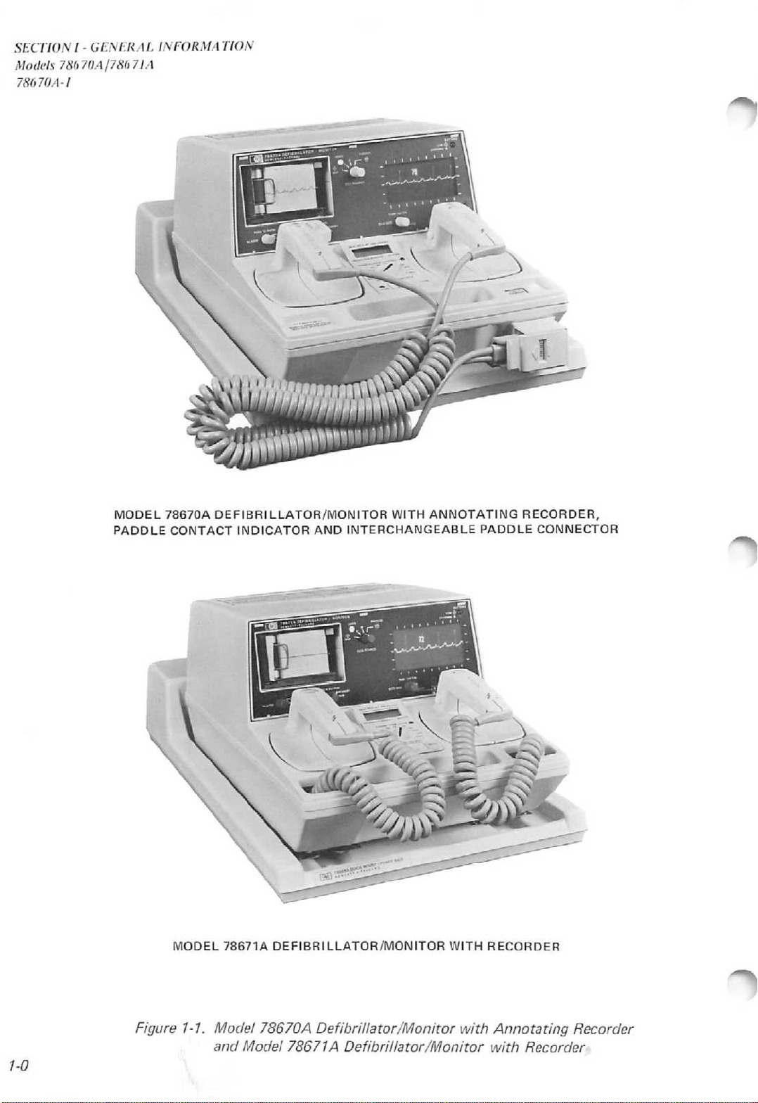
MODEL
PADDLE
78670A
CONTACT
DEFIBRILLATOR/MONITOR
INDICATOR
AND
INTERCHANGEABLE
WITH
ANNOTATING
PADDLE
RECORDER,
CONNECTOR
1-0
MODEL
78671A
Figure 1-1. Model
and
DEFIBRILLATOR/MONITOR
78670
A Defibrillator/Monitor with Annotating Recorder
Model
78671A
Defibrillator/Monitor
WITH
RECORDER
with
Recorder
Page 15
GENERAL
SECTION
INFORMATION
SECTION
I
I -
GENERALINFORMATION
Models
78670A/78671A
78670A-1
1.1
This
INTRODUCTION
manual
contains
service
Defibrillator/Monitors.
mechanical
component
installation
78670-91998
1.2
This
the
number
IDENTIFICATION
manual
same
(XXXXA00000),
separating
instrument
United
The
Defibrillator/Monitor,
plate
The
the
which
serial
instrument
disassembly,
level
information
and
applies
or
lower
prefix
digits
and
the
prefix
was
Kingdom).
serial
is
number
next
troubleshooting
in
the
Model
to
serial
are
identifies
and
manufactured(A=
number
and
attached
for
the
to
the
information
This
circuit
are
78671A
all
Model
number
the
the
the
of
the
to
the
78668A
AC
manual
board
for
covered
78670A
prefix
first
latest
serial
USA;
the
78669A
bottom
Quick-Mount
power
for the
also
contains
Model
removal
both
Operating
four
instruments.
in
the
Guide,
and
78671A
as
that
of
shown
the
ten-digit
modificationofthe
number
C =
Spare
cover,
designates
Canada;
78670A
Battery
near
Power
receptacle.
78670A
complete
and
replacement
Operating
Model
78670A
and the
theory
procedures,
instructions
Operating
of
78671-91998.
Defibrillator/Monitors
on
the
title
instrument
page.
serial
instrument.
the
country
G =
Germany;
Defibrillator/Monitor,
Charger
the
Base
center
is
is
located
in
J =
indicated
of
the
on
Model
78671A
operation,
and
and
Guide,
having
The
serial
number
The
letter
which
Japan;
instrument.
the
this
U =
78671A
on
the
rear
of
Important
manual
provided
manual.
of
which
the
manual
contains corrections for errors within the manual.
On
the
number.
transparencies
of
the
as
well
1.3
Refer
Packard
and
complete
manual
information
to
cover
inablue
These
appear
improvements
supplements
on
current
title
manual
as
INQUIRES
any
pageofthis
This
part
pages.
all
of
pertinent
questions
this
Sales/Service
10-digit
foraworldwide
for
Manual
the
and
number
manual.
The
or
Office.
serial
listing
correcting
Changes
are
keyed
title
page,
accurate.
manual,
can
be
microfiche
Service
comments
Always
number
of
errors,
that
occur
Supplement
to
and are
The
preceding
used
to
Each
microfiche
package
Notes.
regarding
identify
in
the
Hewlett
and
after
inserted
the
manual
revisedasoften
Errata
order
Section
the
manual
6.5x15.2
also
this
the
all
correspondence.
Packard
for
adapting
the
printing
under
print
part
contains
includes
manual
instrument
Sales/Service
the
of
the
front
date
and
as
of
a
Manual
number,isa
cm
(4x6
up
to 60
the
latest
to
the
by
See
contents
the
part
of
manual
cover
of
number,
this
is
the
both
necessarytokeep
Change
sheet
microfiche
inch)
photo
nearest
both
the
Offices.
microfiche
duplicates
manual
Hewlett
model
rear
of
change
number
this
/-/
Page 16
SECTION
Models
78670A-3
I -
GENERAL
78670A/78671A
INFORMATION
1.4
1.4.1
With
indicator
same. The
functions
DESCRIPTION
General
the
exception
DEFIBRILLATOR
Waveform:
Output
20,
and
Charge
paddle.
Charge
360
Delivered
Crystal
delivered
energy.
Armed
light
Safety
to
connected.
Paddle
LED
indicates
contact
Paddles:
Anterior,
electrodes
electrodes.
paddles
Synchronizer:
off
pulseonmonitor
discharge
30
ms.ofmarker
SIZE
Dimensions:
Critically
Energy
30,
50,
360
joules.
Control:
Time:
joules.
Energy
Display
into50ohms
Indicators:
and
digital
Interlock:
50
joules
Contact
bar
graph
qualityofdefibrillator
before
Standard
adult
twist
available.
with
each
point.
and
WEIGHT
of
and
interchangeable
printhead,
and
controls
damped
(Delivered):
70,
100,
Push-buttononapex
Less
Display:
shows
display.
with
Indicator:
arrayonsternum
discharge.
paddles
and
offtoexpose
Full
range
SYNC
detected
indicates
Discharge
pulse.
22.9
cm
sinusoidal.
150,
than10seconds
energy
that
load
and
Charge
done
Output
internal
are
pediatric.
of
indicator
R-wave.
defibrillator
occurs
H x
200
Anterior/
pediatric
31.1
W x47cmL(9"x12.25"x18.50").
Weight:
OPTIONS
A03
C01
C02
C03
C04
12.7kg(28
Delete
connector.
Add
78669A
Charger.
Delete
78668A
Power
Base.
Add
Adult/Pedi
Posterior
Add
Adult
includes
pounds).
interchangeable
Spare
Quick-
Anterior/
Paddles
14412D.
Internal
handle
set,
part
the
paddle
are
5,
10,
300
Liquid
will
self
test
tone,
limited
paddles
3-color
paddle
paddle
Adult
internal
flashes
Marker
within
paddle
Battery
Mount
Paddles;
annotating
deleted
MONITOR
Inputs:
patient
LEADS
indicator
Lead
if
Common
to
with5Kohm
non-isolated
Display
be
3.75
non-fade,
Patient
or
Sweep
Frequency
Heart
from20to
ECG
Calibration:
switch
amplifier.
RECORDER
Annotation:
Paper
40mmoffset
Recorder
(Real
Frequency
BATTERIES
cm
Type:
cadmium.
ORDERING
C05
C06
printhead
paddle
contact
Fault:INOP
patient
secondsofECG
greateratinput
Output:
Size:50mmx30m(100
Time
connector,
indicator,
in
the
ECG
from
cable.
LeadI,II,
position.
lightstoshow
Size&Type:
fixed
Isolation: Twelve (12)
Speed:
Rate
simulates1mV
Modes:
2.0
electrode
set,
LEADSorPADDLES
lead
becomes
Mode
Rejection:
imbalance
ground.
trace.
connector.
25
Response:
Display:
240
BPM.
1V,
Nominal.
Momentary
10
characters/sec
grid.
Delayedby4
available).
Response:
A/hr
number
number
Add
Paddles;
part
pediatric
Add
(3.4
14416A
Pediatric
number
part
Infant
14990B
14993
includes
electrodes
number
cm)
rechargeable nickel-
INFORMATION
(8.1
on
the
78671A
paddlesor3-lead
III
selected
indicator
with
4.5cmx 9cmfor
dataonscreen;
mm/sec
0.5to40
Digital
A.
Internal
Internal
part
Defibrillator/Monitor.
selectable
source.
flashes
disconnected.
112
respect
megohms
nominal.
readout
pushbutton
signaltoECG
nominal.
ft)
with
seconds
0.5to40
and
handle
14992
set,
(5.1
adult
A.
Paddles
number
part
set,
and
cm)
cm)
14990B
the
recorder,
78670A and
paddle
Charge
depleted
Capacity:
in
dischargesor2.5
or
recording.
Charge
dB
Hz
Hz
batteryischarging;
to
is
STANDARD
78668
Redux® Paste, 1 oz.. Part number
651-1029
ECG
Electrode
14151A.Disposable
number
Power
CEE22,
8120-3493-
Recorder
9280-0980.
Adjustment
78660-27800.
Operating
78670-91998
Operating Instruction Card: Part
Number
OPTIONAL
ECG
8120-3164
Sync
78669A
NOTE:
are
L01
L02
L03
N01
N02
Z01
Z02
Z05
900
901
902
906
the
the
connector,and
1.5
low.
Cable,
not
Time:
battery.
hours
Indicator:
A
14445A.
Cable,
2.4
Paper,
5952-6866
Output
Cable,
Spare
Options
available
French
German
Dutch
CSA
VDE/IEC
50HzOperation
100
230
UK
Australian
European
Swiss
Fifty
combined
ACCESSORIES
Quick
Part
number
Lead
Male
m (8
spare
Tool,
Manual:
ACCESSORIES
Cable,
Part
Battery
C03, C04,
with
Labels
Labels
Labels
volt
volt
Power
Power
16
hoursofmonitoring
flashes
Mount
Set,
Configuration
Operation
Operation
paddle
78671A
associated
hours
(50) full
monitoring
Lightison
when
Power
14489B
part
Electrodes,
NEMA-Female
ft)
part
roll,
part
Part
Part
number
Charger
C05
option
Cord
Power
Cord
Power
Cord
Cord
part
A03.
for
Number
14482A.
and
contact
are
the
fully
energy
and
when
battery
Base
number
part
number
number
number
number
C06
1-2
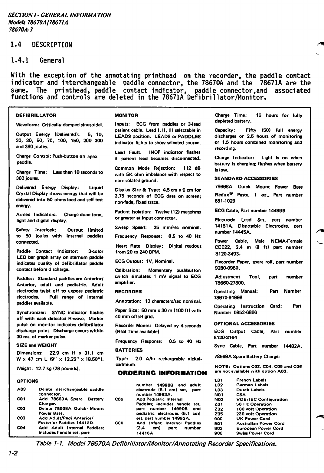
Table 1-1. Model 78670A Defibrillator/Monitor/Annotating Recorder Specifications.
Page 17
SECTION
I -
GENERAL
INFORMATION
Models 78670AJ78671A
78670A-3
DEFIBRILLATOR
Waveform:
Output
50,
Charge
paddle.
Charge
360
Delivered
Crystal
delivered
energy.
Armed
light
Paddles:
Anterior,
electrodes
electrodes.
Synchronizer:
off
pulseonmonitor
discharge
30
ms.ofmarker
Dimensions:
47cmL
Weight:
MONITOR
Inputs:
patient
LEADS
indicator
Lead
patient
Critically
Energy (delivered):
70,100,150,
200,300&360
Control:Push-buttononapex
Time:
joules.
Display
Indicators:
and
with
cable,
position.
Fault:INOP
Less
Energy
shows
into50ohms
digital
display.
Standard
adult
twist
each
point.
(9"x12.25"x18.50").
12.7kg(28
ECG
lightstoshow
lead
paddles
and
offtoexpose
SYNC
detected
indicates
Discharge
pulse.
22.9cmH x
from
LeadI,II,
LEADSorPADDLES
becomes
damped
sinusoidal.
5,10,
20,
joules.
than10seconds
Display:
energy
load
Charge
pediatric.
indicator
R-wave.
pounds)
paddlesor3-lead
III
selected
indicator
Liquid
that
will
and
self
done
are
Anterior/
pediatric
flashes
Marker
defibrillator
occurs
within
31.1cmW x
selectable
source.
flashes
disconnected.
30,
test
tone,
Adult
to
be
in
if
Common
5K
isolated
Display
3.75
non-fade,
Patient
or
Sweep
Frequency
Heart
readout
ECG
Calibration:
switch
amplifier.
RECORDER
Paper
40mmgrid.
Recorder
(Real
Frequency
BATTERIES
Type:
cadmium.
Charge
depleted
Capacity:
dischargesor2.5
1.5
recording.
Mode
ohm
imbalance
ground.
Size&Type:
seconds of ECG
fixed
Isolation:
greateratinput
Speed:
Response:
Rate
from20to
Output:
simulates1mV
Size:50mmx30m(100
Modes:
Time
available).
Response:
2.0
Time:
battery.
hours
combined
ORDERING
Rejection:
112dBwith
with
respecttonon
4.5cmx 9cmfor
dataonscreen;
trace.
Twelve
(12)
connector.
25
mm/sec
megohms
nominal.
0.5to40
Hz.
Display (Optional): Digital
240
BMP.
1V,
nominal
Momentary
(Optional)
Delayedby4
A/hr
16
Fifty
hoursofmonitoring
push-button
signaltoECG
ft)
with
seconds
0.5to40
rechargeable nickel-
hours
(50)
full
monitoring
for
Hz.
fully
energy
and
INFORMATION
Charge
batteryischarging;
is
STANDARD
78668A
low.
Indicator:
ACCESSORIES
Quick
Mount
Lightison
flashes
when
Power
when
battery
Base
Redux® Paste, 1 oz.. Part number
651-1029
ECG
Cable,
Electrode
14151A.
Disposable
14445
a.
Power
CEE22,
8120-1992.
Recorder
9280-0980.
Adjustment
78660-27800.
Operating
78671-91998
Operating
number
OPTIONAL
ECG
8120-3493.
Sync
Cable,
78669A
or
Lead
Cable,
2.4
Paper,
Instruction
5952-6868
ACCESSORIES
Output
Spare
Part
Set,
Electrodes,
Male
m (8 ft)
spare
Tool,
Manual:
Cable,
Part
Battery
number
Part
Part
NEMA-Female
part
roll.
Part
Part
Part
Card:
Part
number
Charger
14489B.
number
number
number
number
number
number
Part
number
14482A.
OPTIONS
A01
Delete
A02
Delete
C01
Add
78669A
Charger
C02
Delete
Power
1.4.2
Model 78670A
The 78670A
1-2)
combined
Energy
is
discrete
The
through
ECG
a
Recorder
Recorder&Heart
Spare
Battery
78668A
Base
is
Quick-Mount
a
with
selectable
steps,
Monitor
three-lead
(400
Rate
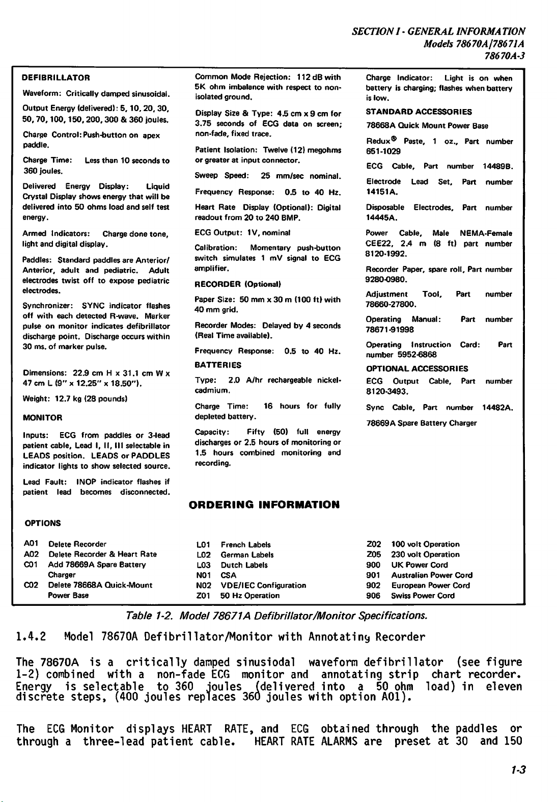
Table 1-2.
L01
L02
L03
N01
N02
Z01
Model
Defibrillator/Monitor
critically
a
non-fade
to
joules
displays
patient
damped
360
replaces
HEART
joules (delivered into a 50
cable.
French
Labels
German
Dutch
Labels
CSA
VDE/IEC
50HzOperation
78671A
sinusiodal
ECG
monitor
360
RATE,
100
volt
230
volt
UK
Power
Australian
European
Swiss
Power
Labels
Configuration
Z02
Z05
900
901
902
906
Defibrillator/Monitor Specifications.
with
Annotating
waveform
and
annotating
Recorder
defibrillator
strip
ohm
joules
and
HEART
with
ECG
RATE
option
obtained
ALARMS
A01).
through
are
preset
Operation
Operation
Cord
Power
Cord
Power
Cord
Cord
(see
figure
chart
recorder.
load) in eleven
the
paddles
at
30 and 150
or
1-3
Page 18
SECTION
Models 78670A/7867IA
786
70A-1
I -
GENERALINFORMALION
BPM.
adjusted
The
DELIVERED
The
which
monitoring
(Quick-Mount
power
power
battery.
battery condition exists.
Mounting
wall
emergency
An
electrodes
battery
1.4.3 Model 78671A Defibrillator/Monitor/Recorder
Size
recorder
73670A
provides
of the
if
desired.
ENERGY,
operates
or
automatically
fifty
1.5
Power
ope
operation
During
the
of
78668A
providesasecure
portable
accessory
operation,
and
storage
Redux
ECG
waveform
PEAK CURRENT and PATIENT
from a
360
joule
hours
Base)
battery
of
is
provided
the
Defibrillator/Monitor
operation,
Quick-Mount
mounting
use.
compartment
paste.
permits
its
is
automatically
annotates
rechargeable
discharges,
combined
DATE/TIME,
monitoring
asastandard
a
BATTERY
Power
The
use
Base
for
the
provides
compact,
in
portable
instrumentaswell
IMPEDANCE
2.0
ampere-hour
or
more
v/hile
LOW
to
the top
convenient
lightweight
applications.
controlled
HEART
than
and
RATE,
during a
2.5
recording.
accessory
simultaneously
indicator
ofacart
storage
package
or
can
be
SELECTED
procedure.
nickel-cadmium
as
hours
and
flashes
or
a
for
of
A
Model
allows
charging
when
vertically
quick
release
patient
design,
manually
ENERGY,
battery
continuous
78668A
AC
line
its
a low
on
for
leads,
along
with
a
The
78671A
and
recorder.
same
as
paddle
non-interchangeable
1.4.4
Fixed
or
monitor
internal
trace
display
appears
The
oldest
written
a
strip
screen
view
at
approx 3.75
1.4.5
Real
time
recorder
trace
Defibrillator/Monitor
The
the
78670A
contact
Monitor
indicator
moving
is
internally
programming
is
to
be
written
information
in
its
place.
chart
and
the
Recorder
recorder.
moves
left
seconds.
or4second
is
internally
with
internal
(78660-60170).
defibrillator
described
on
paddles.
ECG
waveforms
programmed
switch
comparable
from
is
The
New
across
edge
from
of
the
delayed
programmed
programming
combinesaDC
recorder
in
the
sternum
are
to
S2,
mounted
to
a
left
to
erased
moving
by
trace
information
right
screen.
ECG
waveforms
and
Section
1.4.2
paddle,
displayed
display
on
the
conventional
right
a
across
moving
mode
is
to
left.
The
Sweep
are
to
print
eitherareal
switch
defibrillator,
monitor
with
no
on
a
either
memory
oscilloscope
erase
sections
the
following
annotation
4.5
x 9 cm
a
fixed
board
the
screen
bar
before
where
providesadisplay
written
oldest
speed
printed
in
at
information
is
25 mm/sec;
on
the
the
time
SI,
mounted
on
non-fade
are
essentially
exceptions:
on
the
display
or
moving
(78660-60
new
by
repet
new
in
simila
right
dis
dis
recorder
or 4
second
the
ECG
monitor
recorder,
area.
trace
170).
information
itive
formation
r to that of
edge
appears
play
with
Fixed
sweep,
of
from
time
paper.
delayed
memory
board
the
no
and
The
is
the
is
The
1-4
Page 19
SECTION
I -
GENERAL
Models78670A178671A
INFORMATION
78670A-l
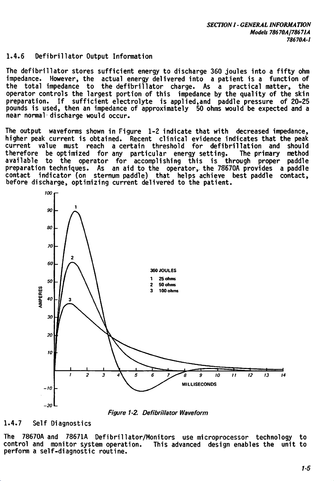
1.4.6
The
impedance.
the
operator
preparation.
pounds
near
The
higher
current value must reach a certain threshold for defibrillation and should
therefore
available
preparation
contact
before
Defibrillator
defibrillator
However,
total
impedance
controls
If
is
used,
normal
output
peak
be
to
then
discharge
waveforms
current
optimized
the
techniques.
indicator
discharge,
100
i-
Output
stores
the
sufficient
the
to
actual
the
largest
sufficient
an
impedanceofapproximately
would
shown
is
obtained.
for
operator
As
(on
sternum
optimizing
Information
energytodischarge
energy
defibrillator
portionofthis
electrolyte
occur.
in
Figure
1-2
Recent
any
an
particular
for
accomplishing
aid
to
the
paddle)
current
deliveredtothe
delivered
charge.
impedancebythe
is
applied,and
indicate
clinical
energy
operator,,
that
helps
360
into
As
50
ohms
that
evidence
setting.
this
is
the
achieve
patient.
joules
a
patientisa
a
practical
qualityofthe
paddle
would
with
decreased
indicates
The
through
'78670A
best
intoafifty
function
matter,
ohm
of
the
skin
pressure
be
expected
of
20-25
and
impedance,
that
the
peak
primary
proper
method
paddle
providesapaddle
paddle
contact,
a
-20
L-
1.4.7
The
control
performaself-diagnostic
Self
78670A
and
Diagnostics
and
78671A
monitor
system
360
JOULES
Figure 1-2.
Defibrillator
Waveform
Defibrillator/Monitors
operation.
routine.
This
advanced
use
microprocessor
design
technology
enables
the
unit
to
to
1-5
Page 20
SECTION
Models 78670A/78671A
78670A-1
Each
control
flash
an
DELIVERED
time
"HP"
ERROR
I -
GENERAL
the
section.
and
CODE
ENERGY
Defibrillator/Monitoristurned
such
INFORMATION
If
all
"888".
display
Ifaproblem
as:
"PI", "P2",
is
refer
O.K.,
the
exists,
"P3",
to
SectionVfor
ON,
DELIVERED
the
DELIVERED
or
"P5".
troubleshooting
a
self
ENERGY
If
an
check
display
ENERGY
ERROR
is
performed
will
display
CODE
information.
alternately
will
flashes
on
the
flash
on
the
1.4.8
Charge
battery
fully
mains
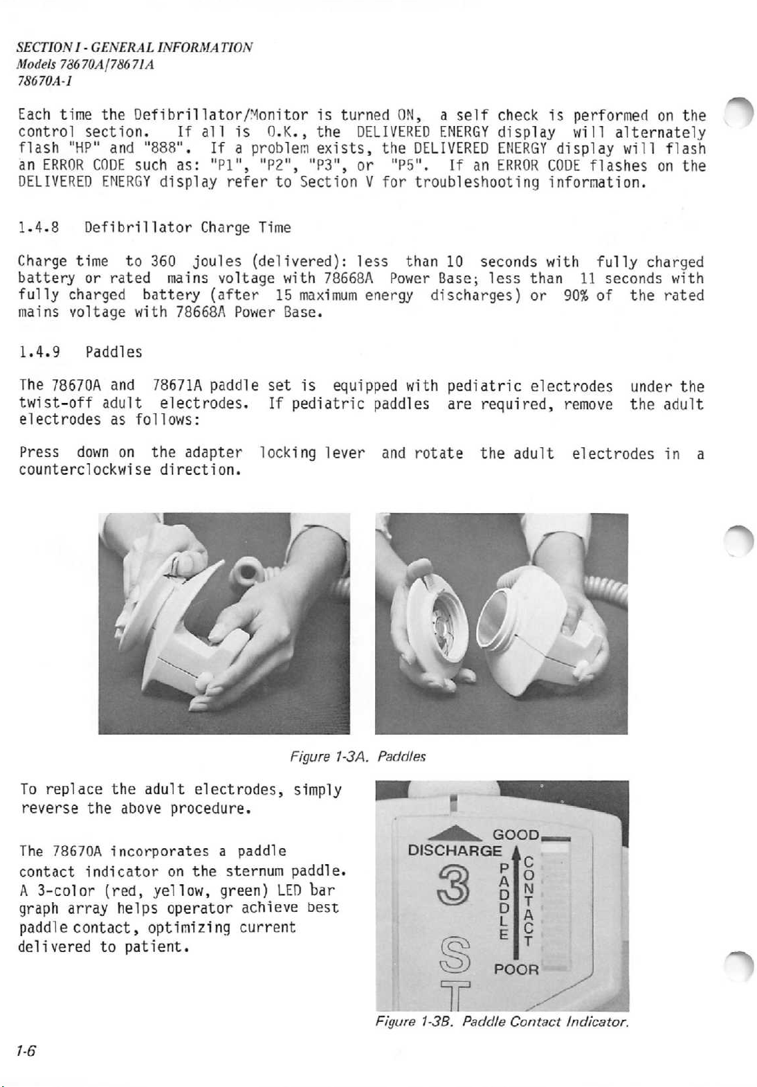
1.4.9
The
twist-off
electrodes
Press
counterclockwise
Defibrillator
time
or
rated
charged
voltage
Paddles
78670A
and
adult
as
down
to
on
Charge
360
battery
with 78668A
joules
mains
78671A
(after
paddle
electrodes.
follows:
the
adapter
direction.
Time
(delivered):
voltage
with
15
Power
Base.
set
If
locking
less
78668A
maximum
is
equipped
pediatric
lever
than
Power
energy
with
paddles
and
10
seconds
Base;
discharges)
pediatric
are
required,
rotate
the
less
with
than
or
90%
electrodes
remove
adult
electrodes
fully
11
of
charged
seconds
the
under
the
with
rated
the
adult
in
a
To
replace
reverse
The
78670A
contact
A
3-color
graph
paddle
delivered
1-6
the
indicator
array
contact,
to
the
adult
above
incorporates
(red,
helps
patient.
yellow,
operator
optimizing
electrodes,
procedure.
a
on
the
green)
paddle
sternum
achieve
current
Figure 1-3A. Paddles
simply
paddle.
LED
bar
best
Figure 1-3B.
Paddle
Contact
Indicator.
Page 21
SECTION
I -
GENERAL
Models 78670A/78671A
INFORMA
TION
78670A-1
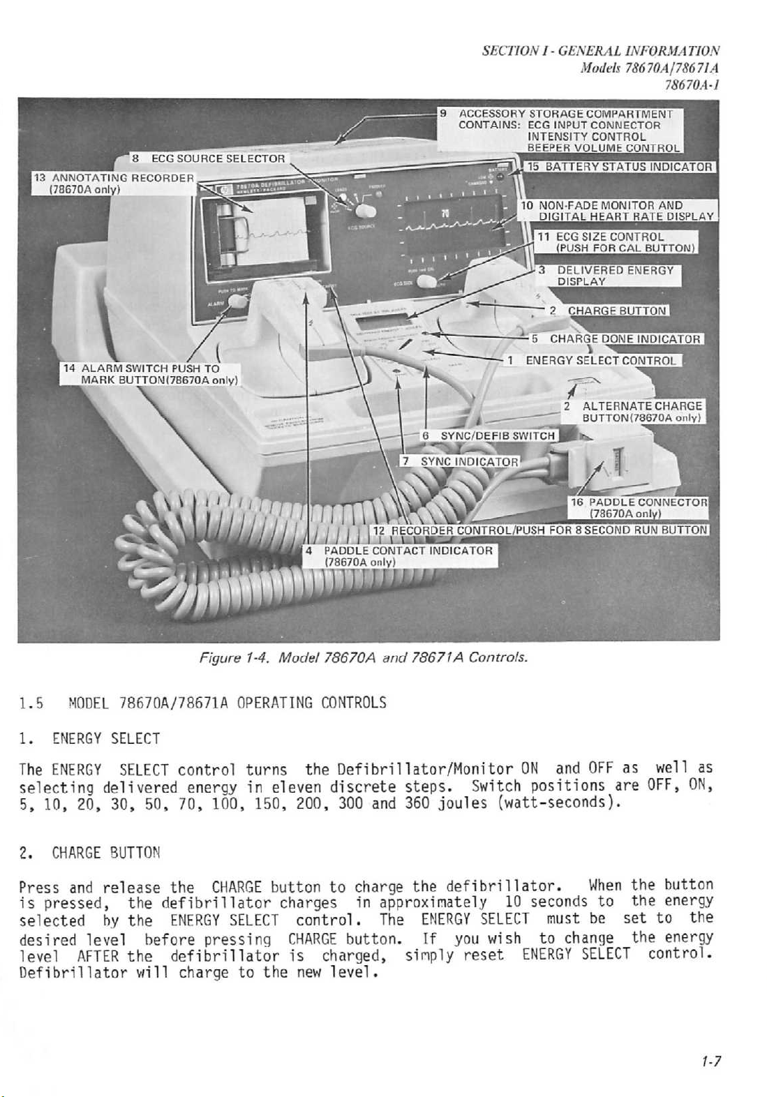
Figure 1-4. Model
1.5 MODEL 78670A/78671A OPERATING CONTROLS
1.
ENERGY
The
ENERGY
selecting
5,
10,
2.
CHARGE
Press
is
pressed,
selected
desired
level
Defibrillator
SELECT
delivered
20,
30, 50,
BUTTON
and
release
by
level
AFTER
SELECT
control
energyineleven
70,
the
the
defibrillator
the
the
ENERGY
before
defibrillatorischarged,
will
charge
turns
100, 150,
CHARGE
SELECT
pressing
to the
button
charges
78670A
the
Defibrillator/Monitor
discrete
200,
300
to
control.
CHARGE
new
button.
level.
and
charge
in
and
78671A
steps.
360
the
Controls.
ON
Switch
joules
defibrillator.
positions
(watt-seconds).
and
approximately10seconds
The
ENERGY
If
simply
you
reset
SELECT
wish
ENERGY
must
to
change
SELECT
OFF
When
to
be
as
are
the
the
set
the
as
well
OFF,
button
energy
to
the
energy
control.
1-7
Page 22
SECTION
Models78670A178671A
78670A-l
3.
The
into
digital
I -
GENERAL
DELIVERED ENERGY
DELIVERED
a 50 ohm
display
ENERGY
INFORMATION
DISPLAY
readout
load
when
permits
easy
indicates
the
defibrillator
viewinginalmost
the
amount
is
any
of
energy
discharged.
ambient
light
which
The
will
condition.
be
liquid
delivered
/*%
crystal,
4. PADDLE
The
PADDLE
contact,
patient.
YELLOW
and
that
5. CHARGE DONE INDICATOR
The
CHARGE
after
indicates
6.
SYNC/DEFIB
The
SYNC/DEFIB
synchronous
CONTACT
CONTACT
before
When
to
GREEN
sufficient
DONE
the
charge
when
INDICATOR
discharge.
the
paddles
as
patient
indicator
button
the
defibrillatorisarmed
SWITCH
switch
(SYNC)
indicator
This
are
impedance
electrolyte
lights
is
pressed
selects
mode
of
operation.
applied
dischargesassoonasbothofthe
the
SYNC
waveform
pressed.
The
defibrillator
is
turned
(SYNC
by
moving
instrument off and on.
mode,
the
indicated
on.
For
position).
the
switch
defibrillator
by
the
marker
automatically
synchronized
The
defibrillator
momentarily
on
the
helps
is
applied.
when
either
sternum
the
to
the
decreases-indicating
the
and
released.
and
the
discharge
will
pulse
sets
operation,
dischargeatthe
—
itselftothe
move
canbereset
back
to
paddle
user
optimize
patient,
defibrillator
In
addition,
ready
for
instant
In
the
DEFIB
buttonsonthe
after
the
both
DEFIB
the
for
DEFIB
discharge
switch
instant
indicates
current
the
LED
proper
reaches
discharge.
defibrillation
mode,
paddles
first
mode
the
best
deliveredtothe
changes
a
from
paddle
selected
CHARGE
DONE
(DEFIB)
the
when
defibrillator
are
pressed.
point
on
buttons
the
instrument
have
momentarilytothe
dischargeatany
positionorturning
paddle
RED
to
pressure
energy
TONE
or
In
the
ECG
been
left
time
this
Note:
position.
go
7. SYNC INDICATOR
The
mode
8. ECG SOURCE SELECTOR
The
cable
selectedinthe
will
condition.
1-8
For
synchronized
If
the
into
the
sync
SYNC
of
ECG
indicator
operation.
SOURCE
selector
(LEADS)orECG
flash
should
ECG
mode.
flashes
LEADS
an
operation,
SOURCE
selectorisin
off
selects
pickupfrom
with
the
paddles
the
ECG
SOURCE
the
each
detected
sourceofthe
(PADDLES).
PADDLES
R-wave
incoming
position.Inaddition,inthe
electrode
become
disconnected,
selector
LEADSI,II
LEADS
must
position,
during
ECG
position,
be
in
the
unit
the
synchronized
signal:
and
the
the
3-lead
III
indicator
indicatinganINOPerative
will
may
LEADS
NOT
ECG
be
Page 23
9.
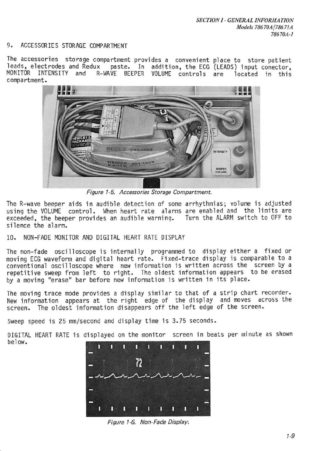
ACCESSORIES
The
accessories storage
leads,
MONITOR
compartment.
electrodes
INTENSITY
STORAGE
and
and
COMPARTMENT
compartment
Redux
R-WAVE
paste.
BEEPER
SECTION
I -
GENERAL
Models 78670A/78671A
INFORMATION
78670A-1
provides a convenient place to store patient
In
addition,
VOLUME
the
controls
ECG
(LEADS)
are
located
input conector,
in
this
Figure 1-5. Accessories Storage Compartment.
The R-wave
using
the
exceeded,
silence
10.
NON-FADE MONITOR
The
non-fade
moving
conventional
repetitive
by a
moving
The moving
New
information appears at the right
screen.
Sweep
DIGITAL
below.
VOLUME
the
the
ECG
The
speed
HEART
beeper
alarm.
aids
control.
beeper
provides
AND
oscilloscope
waveform
and
oscilloscope
sweep from
"erase"
trace
mode
oldest
is
25 mm/second and
left
bar
provides
information
RATEisdisplayed
in
audible
DIGITAL
digital
where
before
When
is
to
detection
heart
an
audible
HEART RATE
internally
heart
new
information
right.
new
information
a
display
disappears
display
on
the
of
some
rate
alarms
warning. Turn
DISPLAY
programmed
rate.
Fixed-trace
is
The
oldest
is
similar
edge
off
time
monitor
to
of the display
the
is
3.75
screen
arrhythmias;
are
enabled
the
to
display
display
written
information
written
that
left
in
of a
edge
seconds.
in
beats
and
ALARM
across
appears
its
strip
and
of
the
per
volume
the
switch to
either
is
comparable
the
place.
chart
moves
screen.
minute as
is
adjusted
limits
OFF
a
fixed
screen
to
be
erased
recorder.
across the
are
to
or
to
a
by
a
shown
Figure 1-6. Non-Fade Display:
1-9
Page 24
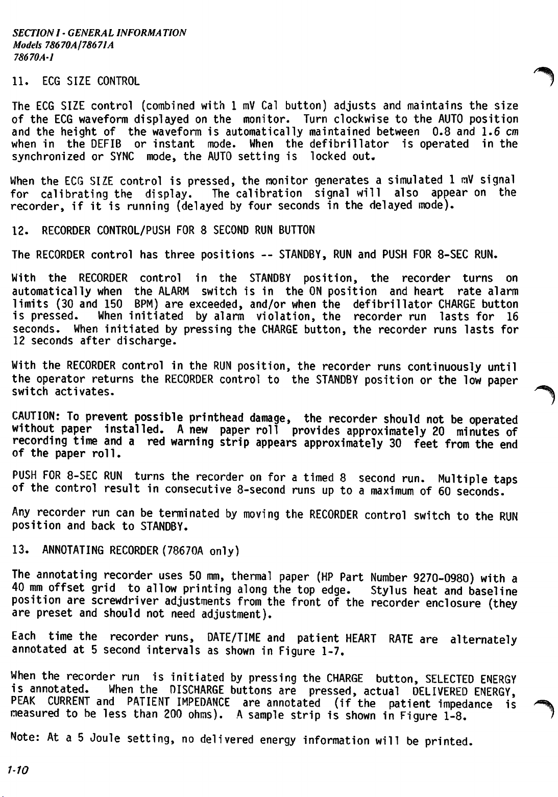
SECTION
Models 78670A178671A
78670
A-l
I -
GENERAL
IN
FORMATION
11.
The
of
and the
when
synchronized
When
for
ECG
SIZE
ECG
SIZE
the
ECG
waveform
height
in
the
the
ECG
calibrating
CONTROL
control
DEFIB
or
SIZE
recorder,ifit
12.
RECORDER
The
RECORDER
With
automatically
limits
is
seconds.
12
With
the
switch activates.
the
(30
pressed.
seconds
the
operator
CONTROL/PUSH
control
RECORDER
when
and
When
When
after
RECORDER
returns
(combined
displayed
of the
SYNC
controlispressed,
the
is
150
initiated
discharge.
waveform
or
instant
mode,
display.
running
has
three
control
the
ALARM
BPM)
are
initiated
by
with1mV
on
the
(delayedbyfour
FOR8SECOND
positions
in
switch
exceeded,
by
pressing
controlinthe
the
RECORDER
the
monitor.
is
automatically
mode.
AUTO
The
the
alarm
RUN
When
setting
the
calibration
RUN
STANDBY
is in
and/or
violation,
the
position,
control
Cal
button)
Turn
maintained
the
defibrillator
is
locked
monitor
generatesasimulated1mV
signal
secondsinthe
BUTTON
—
STANDBY,
position,
the
ON
when
the
the
CHARGE
to
button,
the
the
recorder
STANDBY
adjusts
clockwise
out.
and
between
will
delayed
RUN
and
PUSH
the
position
defibrillator
recorder
the
recorder
runs
positionorthe
maintains
to the
is
also
AUTO
0.8 and 1.6 cm
operated
appear
mode).
FOR
8-SEC
recorder
and
heart
CHARGE
run
lasts
runs
continuously
the
position
in
signal
on
RUN.
turns
rate
alarm
button
for
lasts
until
low
paper
size
the
the
on
16
for
CAUTION:Toprevent
without
recording
of
the
PUSH
of
the
Any
position
13.
The
40
mm
position
are
Each
annotatedat5
When
is
annotated.
PEAK
measuredtobe
paper
paper
FOR
8-SEC
control
recorder
and
ANNOTATING
annotating
offset
are
preset
time
installed.Anew
time
andared
roll.
RUN
resultinconsecutive
run
back
RECORDER
recorder
grid
screwdriver
and
should
the
recorder
second
the
recorder
When
CURRENT
and
less
canbeterminatedbymoving
to
to
run
PATIENT
than
possible
turns
printhead
warning
the
recorderonforatimed8second
damage,
paper
strip
roll
appears
8-second
the
STANDBY.
(78670A
uses50mm,
allow
adjustments
not
need
runs,
intervalsasshowninFigure
is
initiatedbypressing
the
DISCHARGE
IMPEDANCE
200
only)
thermal
printing
adjustment).
ohms).Asample
along
from
DATE/TIME
the
the
and
buttons
are
annotated
paper
are
the
recorder
provides
approximately20minutes
should
notbeoperated
approximately30feet
run.
Multiple
runsuptoamaximumof60
RECORDER
(HP
top
edge.
frontofthe
patient
1-7.
the
CHARGE
pressed,
Part
HEART
(if
control
Number
Stylus
recorder
RATE
button,
actual
the
patient
switchtothe
9270-0980)
heat
enclosure
are
SELECTED
DELIVERED
impedanceis^
stripisshowninFigure
of
from
the
end
taps
seconds.
RUN
and
baseline
with
a
(they
alternately
ENERGY
ENERGY,
1-8.
/
Note:Ata 5
1-10
Joule
setting,nodelivered
energy
information
willbeprinted.
Page 25
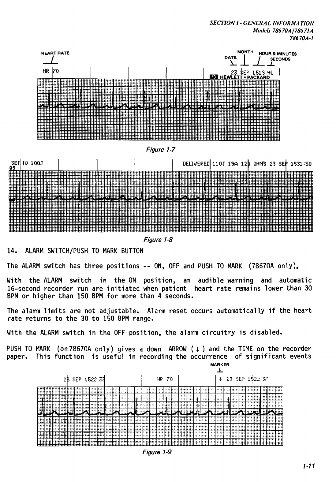
SECTION
I -
GENERAL
INFORMATION
Models 78670A/786 71A
78670A-1
HEART
RATE
Figure
/-7
DELIVERED
MONTH
DA\E
_
KM
23
HEWLETT »PACKARD
110J
:|:EP
19A12J
H0UR&M|NUTES
/
SECONDS
1513:f0
OHf-fS
23 SEP
1531:50
14.
ALARM SWITCH/PUSH TO MARK BUTTON
The
ALARM
With
the
16-second
BPM or
The
rate
With
PUSH
paper.
higher
alarm
returns
the
TO
MARK
This
switch
ALARM
recorder
limits
than
has
three
switch
run
150 BPM
are
not
to the 30 to 150 BPM
ALARM
switch
in
(on78670A
function
^
EP
15
t
t
~*
*K
4
i
i
u ,t#
rl
i,ti
r
V
**
i
$ *. -
ii.t
-
r .
positions--ON,
in the ON
are
initiated
for
more
adjustable.
the
OFF
position,
only)
is
-
•!"
givesadown
useful
,-
i
Wi—
'
in
Figure 1-8
OFF
and
PUSH
TO
position,
when
patient
an
audible
heart
rate
than4seconds.
Alarm
reset
occurs
automatically
range.
the
alarm
ARROW
recording
| 1 J \
1 A
.1
Figure 1-9
HF:
jl
,7I1
the
I
II
ill'
circuitry
(\ )
and
occurrence
MA
I
jl
1
:
tt
kRKER
X
•i-
MARK
warning
remains
is
the
TIME
of
5 S
EP
2~-
J
it.,
(78670A
only).
and
lower
if
disabled.
on
the
significant
2 •?.?
l£l
;
,
•
t
t
t
,1
.1
automatic
than
30
the
heart
recorder
events
i
1
I
1
1-11
Page 26
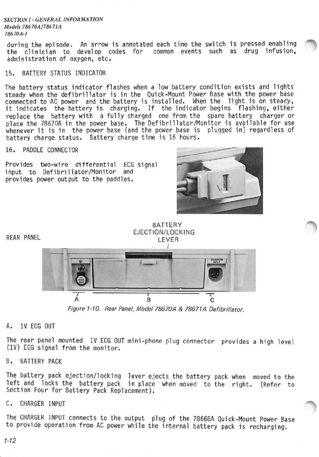
SECTIONI-GENERAL
Models78670A/78671A
78670A-1
INFORMATION
during
the
administration of
15.
The
steady
connectedtoAC
it
replace
place
the
clinician
BATTERY
battery
when
indicates
the
the
78670Ainthe
episode.Anarrowisannotated
STATUS
status
the
the
battery
wheneveritis in
battery
16. PADDLE
Provides
input
provides
charge
two-wire
to
power
status.
CONNECTOR
Defibrillator/Monitor
output
to
develop
oxygen,
INDICATOR
indicator
codes
etc.
flashes
defibrillatorisin
power
and
battery
with
the
power
differential
to
the
is
charging.
a
fully
power
base.
base
Battery
the
paddles.
battery
charge
and
for
whenalow
the
is
charged
The
(and
the
time
ECG
signal
each
time
the
switchispressed
common
Quick-Mount
installed.
If
the
one
events
battery
Power
When
indicator
from
the
such
condition
Base
spare
the
begins
with
light
battery
as
drug
exists
the
is
flashing,
infusion,
and
power
on
charger
Defibrillator/Monitorisavailable
power
is
base
16
is
hours.
plugged
in)
regardless
enabling
lights
base
steady,
either
or
for
use
of
*>
REAR PANEL
A. IV ECG OUT
The
rear
panel
(IV)
ECG
signal
B.
BATTERY
The
battery
left
and
Section
PACK
pack
locks
Four
A B C
Figure 1-10. Rear Panel, Model
mountedIVECG
from
the
monitor.
OUT
ejection/locking
the
for
battery
Battery
pack
Pack
Replacement).
BATTERY
EJECTION/LOCKING
LEVER
/
78670A&78671A
mini-phone
lever
in
place
plug
ejects
when
connector
the
battery
moved
Defibrillator.
providesahigh
pack
to
the
when
movedtothe
right.
level
(Refer
to
C.
The
to
provide
1-12
CHARGER
CHARGER
operation
INPUT
INPUT
connectstothe
fromACpower
output
while
plugofthe
the
internal
78668A
Quick-Mount
battery
Power
Base
packisrecharging.
Page 27
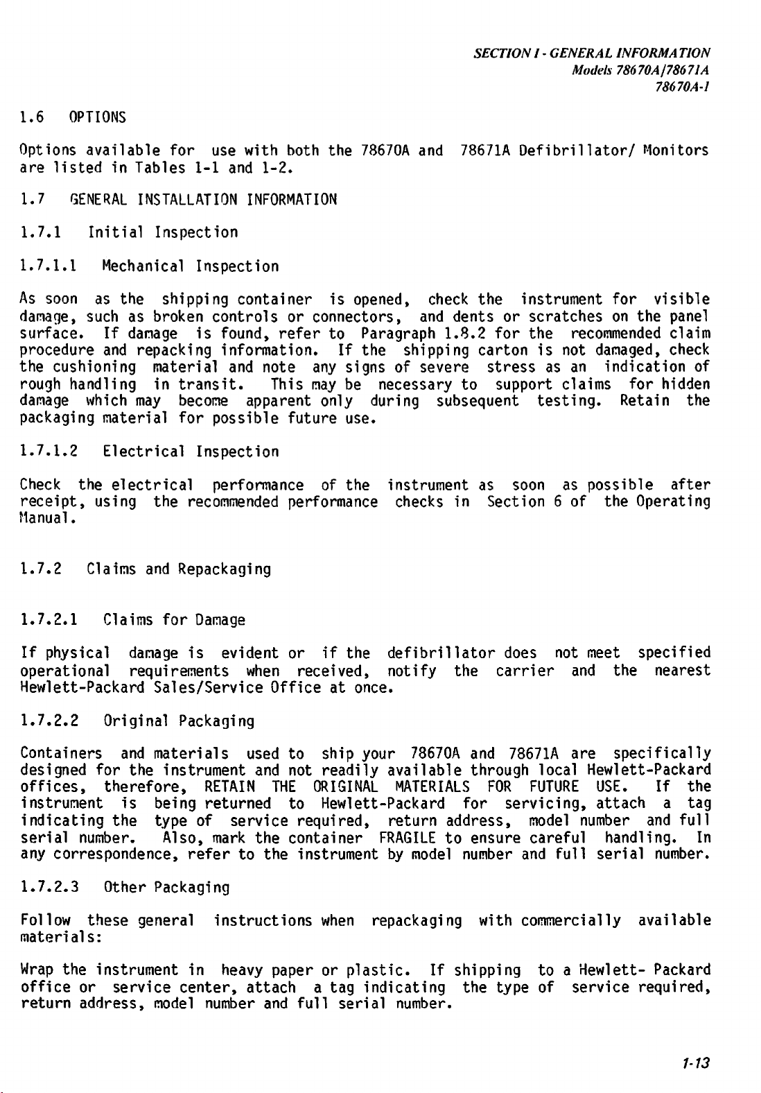
SECTION
I -
GENERAL
Models 78670Aj78671A
INFORMA
TION
78670A-1
1.6
Options
are
1.7 GENERAL INSTALLATION INFORMATION
1.7.1
1.7.1.1
As
damage,
surface.
procedure
the
rough
damage
packaging
1.7.1.2
Check
receipt,
Manual.
OPTIONS
available
listed
in
Initial
Mechanical
soon
as
such
If
and
cushioning
handling
which
material
Electrical
the
electrical
using
for use
Tables
Inspection
the
as
broken
shipping
damage
repacking
material
in
may
the
with
1-1
and
Inspection
container
controls
is
found,
information.
and
transit.
become
for
apparent
possible
Inspection
performance
recommended
both
1-2.
or
connectors,
refer
note
This
any
may be
future
performance
the
is
to
If
only
of
78670A
opened,
Paragraph
the
signs
of
necessary
during
use.
the
instrument
checks
and
78671A
check
and
dents
1.8.2
shipping
severe
to
subsequent
in
the
or
for
carton
stress
support
as
soon
Section
Defibrillator/
instrument
scratches
the
is
not
as
an
claims
testing.
as
6 of
for
on the
recommended
damaged,
indication
Retain
possible
the
Monitors
visible
panel
claim
check
for
hidden
after
Operating
of
the
1.7.2
1.7.2.1
If
operational
Hewlett-Packard
1.7.2.2
Containers
designed
offices,
instrument
indicating
serial
any
1.7.2.3
Follow
materials:
Wrap
office
return address,
Claims
Claims
physical
damage
requirements
Original
and
for
the
therefore,
is
the
number.
correspondence,
Other
these
the
instrument
or
service
and
Repackaging
for
Damage
is
Sales/Service
Packaging
materials
instrument
being
type
of
Also,
refer
Packaging
general
in
center,
model
evident
or
when
Office
used
to
and
not
RETAIN
returned
THE
to
service
mark
the
to the
container
instructions
heavy
paper
attach
number and
if
the
received,
at
ship
readily
ORIGINAL
defibrillator
notify
once.
your
available
Hewlett-Packard
required,
instrument
when
or
a
tag
full
serial
return
FRAGILE
by
repackaging
plastic.
indicating
the
78670A
MATERIALS
address,
to
model
If
shipping
number.
carrier
and
through
FOR
for
ensure
number
with
the
type
does
not
and
78671A
are
local
FUTURE
servicing,
model
careful
and
number
full
commercially
to a
of
Hewlett-
service
meet
specified
the
nearest
specifically
Hewlett-Packard
USE.
attach
handling.
serial
If
a
and
full
number.
the
tag
In
available
Packard
required,
1-13
Page 28
SECTIONI-GENERAL
Models78670A/78671A
78670A-1
Use
a
strong
material
Use
enough
instrument
Protect
Seal
the
the
shipping
is
adequate.
shock
to
provide
control
shipping
INFORMATION
container.
absorbing
firm
panel
with
container
A
material
cushioning
cardboard.
securely.
double-wall
(3
or4inch
and
to
prevent
carton
layer)
movement
made
of
around
inside
all
350
sides
the
pound
test
of
the
container.
Mark
the
shipping
1.8
Refer
procedures.
1.9
1.9.1
The
vibration,
Preparing
to
ENVIRONMENT
Operating
location
excessive
all
options
Temperature:
Relative
Altitude:
container
for
Section
Environment
of
your
dust,
corrosive
humidity.
is:
-20
131
degrees
Humidity:
4,500m(15,000
FRAGILE
to
ensure
careful
Operation
6
of
the
Operating
Defibrillator/Monitor
or
explosive
The
operating
environment
Manual
vapors
for
should
or
for
degreesCthrough55degreesC(-4
F)
5%
through
ft)
95%
max
handling.
checkout
gases,
the
78670A
be
extreme
and
reasonably
and
degreesFthrough
installation
free
temperature
78671A
including
from
and
Note:
(32
should
Instrument
degrees
not
through
be
used
meets
on
all
131
the
specifications
degrees
78668A
F).
Power
For
Base
from
zero
maximum
below
degrees
battery
zero
degrees
C to
life
55
degrees
the
instrument
C
(32
degrees
F).
WARNING:
OR
WHERE
OR EMERGENCY VEHICLE-MOUNTED DEFIBRILLATORS AROUND AUTO WRECKS. SPILLED GASOLINE
AND PUDDLES OF WATER PRESENT EXTREMELY DANGEROUS EXPLOSION AND SHOCK HAZARDS.
1.9.2
The
Temperature:
Altitude:
Relative
1-14
DO
NOT
USE
THE
DEFIBRILLATORINA
CONCENTRATIONSOFFLAMMABLE
Storage
storage
and
-40
and
Shipment
shipping
environment
degreesCthrough65deqreesC(-40
9,000m(30,000
humidity:
5%
through
Environment
ft)
max
95%
FLAMMABLE
ANESTHETICS
for
the
78670A
ATMOSPHERE
MAY
OCCUR).
and
78671A
degrees
(i.e.
AVOID
are:
through
OXYGEN
USING
149
TENTS
PORTABLE
degrees
C
F)
Page 29
SECTION
I -
GENERAL
Models 78670A/78671A
INFORMATION
78670A-1
1.10
The
instruments
nominal)at50-60
In
50-60
1.11
To
grounded.
cable
appropriate
identified
WARNING:
OUTLET. A HOSPITAL GRADE OUTLET IS RECOMMENDED. NEVER ADAPT THE 3-PRONG PLUG FROM
THE
IS REPLACED WITH A 3-SLOT GROUNDED OUTLET.
The
360
unplugging
The
buttons
defibrillator
charged
POWER
Model
78668A
addition,
Hz
is
INSTRUMENT
protect
Accordingly,
which
and
FOR
MONITOR
78670A
Joules.
ENERGY
and
the
pressed
for
REQUIREMENTS
Quick-Mount
will
operate
Hz
with
operation
possible
with
GROUNDING
hospital
grounds
3-wire
described
PROPER
TO
FITA2-SLOT
78671A
Simply
power
SELECT
is
more
personnel
the
receptacle.
GROUNDING,
store
removing
base
switch
to
discharge
designed
than 32
(MODEL
from
the
from
the
AND
the
78668A
Power
a
78668A
a
line
line
POWER
and
Power
Base
line
voltageof200
selectorinthe
the
Base
instrumenttothe
Available
in
Table
OUTLET.
high
will
must
to
seconds.
1-3,
THE
voltage
the
defibrillator
not
remove
be
placed
a
charged
automatically
POWER
allows
voltage
rear
CORD
patient,
is
Power
POWER
IF
THE
energy
BASE)
AC
operationofboth
of
from
panel
line
to
230
SETS
(78668A
the
equipped
power
power
Cable
RECEPTACLE
OUTLET
with
line
Sets.
HAS
and are
from
power
instrument.
fromabattery-powered
in
the
discharge
OFF
models.
100
selectorinthe
250
Vac
to
(230
130
Vac
115
Vac
(115
position.
nominal)
position.
POWER
Power
a
ground
sets,
MUST
ONLY
BASE)
Base
must
detachable
when
USA
BE A
TWO
plugged
and
3-WIRE
SLOTS,
be
properly
3-wire
non-USA
GROUNDED
SEE
capableofdeliveringupto
the
Quick-Mount
position
As
a
safety
internally
or
the
if
Power
instrument.
discharge
feature,
it
has
power
into
THAT
Base
The
Vac
at
an
are
IT
or
the
been
The
78670A
shock
ground,
static
the
hazard.
small
charges
exposed
housing).
1.12
Mounting
6
of
MOUNTING
the
and
78671A
Becauseabattery-powered
static
present
metal
Avoid
touching
(78668A
instructions
Operating
are
charges
a
surfaces
POWER
for
Manual.
designed
with
all
plastic
instrument
can
be
minor
(ground
these
generated
shock
potential
connector
surfaces
during
during
to
connector,IVECG
battery
BASE)
the
78668A Quick-Mount Power Base
covers
defibrillator
the
and
controlstominimize
has
no
operator,
operation.
are
reference
discharges.
BUT
ONLY
OUT,
located
and
in
to
earth
The
through
recorder
Section
1-15
Page 30
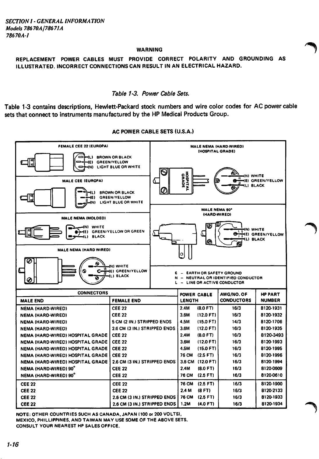
SECTION
I -
GENERAL
Models 78670A/78671A
78670A-l
INFORMATION
WARNING
REPLACEMENT
ILLUSTRATED.
POWER
INCORRECT
CABLES
CONNECTIONS
MUST
Table
PROVIDE
CAN
RESULT
1-3.
Power
CORRECT
IN
AN
Cable
POLARITY
ELECTRICAL
Sets.
AND
HAZARD.
GROUNDING
AS
Table 1-3 contains descriptions, Hewlett-Packard stock numbers and wire color codes for AC power cable
sets
that
connecttoinstruments
FEMALE
^-
3"
c
•
MALE
Cffl
MALE
MSC
CEE22IEUROPA)
CEE
NEMA
f^,
#V-(E)
[_—*-^-(Ll
manufacturedbythe
AC
<L)
BROWNORBLACK
<E)
GREEN/YELLOW
iN)
LIGHT
BLUEORWHITE
(EUROPA)
<L)
—HE)
—<N)
BROWNORBLACK
GREEN/YELLOW
<N)
LIGHT
BLUEORWHITE
(MOLDED)
WHITE
GREEN/YELLOWORGREEN
BLACK
POWER
HP Medical
CABLE
c
SETS
0
0
Products
(U.S.A.)
o o
3)
(/>
>2
Oh
m ^
r
MALE
NEMA
(HOSPITAL
(.
MALE
(HARDWIRED)
Group.
(HARD-WIRED)
GRADE)
NEMA
<N>
WHITE
E)
GREEN/YELLOW
ID
BLACK
S0°
<N>
WHITE
E)
GREEN/YELLOW
<L)
BLACK
/^%
MALE
NEMA
NEMA
NEMA
NEMA
NEMA
NEMA
NEMA
NEMA
NEMA
NEMA
NEMA
CEE
22
CEE
22
CEE
CEE
22
NOTE:
MEXICO,
CONSULT
END
(HARD
(HARD
(HARD
(HARD
(HARD
(HARD
(HARD
(HARD
(HARD
(HARD
(HARD
22
OTHER
PHILIPPINES,
YOUR
MALE
NEMA
•WIRED)
WIRED)
WIRED)
•WIRED)
•WIRED)
•WIRED)
WIRED)
WIRED)
•WIRED)
•WIRED)
WIRED)
HOSPITAL
HOSPITAL
HOSPITAL
HOSPITAL
HOSPITAL
90°
90°
COUNTRIES
NEAREST
(HARD
WIRED)
C-~r-(E)
CONNECTORS
GRADE
GRADE
GRADE
GRADE
GRADE
SUCHASCANADA.
AND
TAIWAN
HP
SALES
OFFICE.
<N)
WHITE
GREEN/YELLOW
'L)
BLACK
FEMALE
CEE
CEE
5 CM (2
2.6
CEE
CEE
CEE
CEE
2.6
CEE
CEE
CEE
CEE
2.6
2.6
MAY USE
END
22
22
IN.)
STRIPPED
CM (3 IN.)
22
22
22
22
CM (3
IN.)
22
22
22
22
CM (3
IN.)
CM (3 IN.)
JAPAN
(100or200
SOMEOFTHE
STRIPPED
STRIPPED
STRIPPED
STRIPPED
ENDS
ENDS
ENDS
ENDS
ENDS
VOLTS).
ABOVE
E -
EARTHORSAFETY
N -
NEUTRAL
L -
LINEORACTIVE
POWER
LENGTH
2.4M
3.6M
4.5M
3.6M
2.4M
3.6M
4.5M
76
CM
3.6
CM
2.4M
76
CM
76
CM
2.4
M
76
CM
1.2M
SETS.
CABLE
(8.0
(12.0
(15.0
(12.0
(8.0
(12.0
(15.0
(2.5
(12.0
(8.0
(2.5
(2.5
(8
(2.5
(4.0
FT)
OR
FT)
FT)
FT)
FT)
FT)
FT)
FT)
FT)
FT)
FT)
FT)
FT)
FT)
FT)
GROUND
IDENTIFIED
CONDUCTOR
AWG/NO.
CONDUCTORS
CONDUCTOR
16/3
16/3
14/3
16/3
16/3
16/3
16/3
16/3
16/3
16/3
16/3
16/3
16/3
16/3
16/3
OF
HP
PART
NUMBER
8120-1931
8120-1932
8120-1706
8120-1935
8120-3493
8120-1993
8120-1995
8120-1996
8120-1994
8120-0609
81200610
8120-1900
8120-2133
8120-1933
8120-1934
/-%
1-16
Page 31

SECTION
I -
GENERAL
Models
INFORMA
TION
78670A178671A
78670A-1
EAST
AND
UNITED
LIGHT
GREEN/YELLOW
BROWN
AUSTRALIA.
LIGHT
BLUEORBLACK
GREEN/YELLOW
LIGHT
BROWNORRED
GREAT
RHODESIA.
LIGHT
GREEN/VELLOW
LIGHT
WEST
ARAB
BLUE
BRITIAN.
SINGAPORE
BLUE
BROWN
REPU8LIC
NEW
EUROPE.
ZEALAND
IN
CYPRUS.
IE
IL
SAUDI
NIGERIA.
ARABIA.
Table 1-3.
AC
Power
POWER
MALESCHUKO
Cable
CABLE
8120
8170
8120
8120
8120
SETS
1609120ml
1692120m.
1460124m.
1690
8120
Ifil
NOTE:
Sets
(Continued).
(NON
FEMALE
FEMALE
14 S
ml
1369172ml
122ml
OTHER
POWER
CORD
SALES
USA)
FEMALE
ENOISRIGHT
ENOISSTRIPPED!
FEMALE
E
FEMALE
COUNTRIES
CABLE
CONFIGURATIONS.
SETINYOUR
OFFICE.
CEE22(EUROPA)
ANGLEl
CEE22(EUROPA)
&
CEE22(EUROPA)
USE
MORE
THAN
AREA,
CONSULT
BROWN
El
GREEN'VELLOW
Nl
LIGHT
ILI
LIGHT
IEI
GREEN/VELLOW
INI
LIGHT
II
LIGHT
El
GREEN'VELLOW
Nl
LIGHT
ONEOFTHE
FOR
CORRECT
YOUR
BLUE
BROWNORRED
BLUEORBLACK
BROWN
BLUE
POWER
NEAREST
ABOVE
HP
1.13 OPTIONAL ACCESSORY CABLES
Synchronizing
The
78670A
signal
is
High
When
througha1000:1
available
Level
it
accessory
angle
mini-phone
fromaBedside
and
78671A
can
divider,tothe
for
this
ECG
Output
is
necessarytoconnect
cable
is
plug
application
Cable
available
on
one
Monitor
be
externally
end
synchronizedbyapplyingahigh
ECG
(P/N
14482A).
the1volt
(P/N
8120-3164).
andastandard
LEADS
ECG
This
phone
input.
output
(8)
plugonthe
A
molded
to*another
foot
cable
other
cable
level
assembly
ECG
instrument,
has
a
right
end.
an
1-17
Page 32

SECTION
I -
GENERAL
Models 78670A178671A
78670A-4
INFORMATION
STERILIZATION
AUTOCLAVING
Only
the
internal paddles supplied with
275°
F (135°C) maximum. To maintain sterility after autoclaving, good packaging isessential.
The
high
temperature
autoclaving
withstand
discharge
GAS
STERILIZATION
The
paddles
to
the
following
upto200
switch.
and
other
gas
shorten
defibrillator
sterilization
OF
and
humidity
their
useful life. Typically, HP's internal
autoclave
procedure:
HEWLETT-PACKARD'S
the
defibrillator are autoclavable (autoclave
NOTE
to
cycles
which
before
the
paddles
sustaining
accessories (cables, etc.) will
INTERNAL
are
exposed
damagetothe
notbedamaged
PADDLES
during
paddles
cables
when
temperature
can
or
subjected
1.
Clean
2.
Dry
oxide
3. Use
Freon-12).
4.
Follow
with
a.
b.
c.
the
exterior
the
item
completelytoavoid
sterilization.
ethylene
the
operating
these
reminders:
When
54.4°
sterilizing
C (130° F). Temperatures
reliabilityofthe
Maximum
At
the
of
the
oxide/freon
instructions
the
itemordamage
gas pressure
end
of
the
item
mixtureasthe
external
sterilization
for5to15minutestoexpel
to
be
sterilized
formationoftoxic
provided
paddles,
its
components.
nottoexceed
cycle,
someofthe
to
remove
ethylene
sterilant
by
sterilizer
that
6 psi
(12%
the
manufacturerofthe
temperature
exceed this limit could affect the
(310
use
vacuum
surface
glycol
ethylene
mmHg)
(-26
contamination.
during
oxide
must
forupto
inches
of
residual gas.
ethylene
with
gas
sterilizer
not
six
mercury)
88%
exceed
hours.
1-18
Page 33

SECTIONII-
THEORYOF
OPERA
Models 78670AJ78671A
78670A-2
TION
2.1
This
INTRODUCTION
section
describes
the
THEORY
theory
SECTION
OF
of
II
OPERATION
operation
of
the
78670A
Defibrillator/Monitors. The first section is a brief overview with
block
2.2
Refer
boards:
board.
The
section
section.
ECG
LEADS
diagram.
SYSTEM
to the
an
ECG
analog
which
RA fc
LA fc
ECG
SWITCH
78670-60215
BD
RL
The
OVERVIEW
block
diagram,
switch
board
isolates
ANALOG
78670-
FLOATING1GROUNOED
SECTION1SECTION
second
is
the
ECG
BD
60155
1
1
section
Figure
board,
divided
patient
an
covers
2.1.
analog
into
from
potentially
ECG
DIGITAL
78660-60140
uP
circuit
The
ECG
input
two
BD
theory
section
board
sections,
unsafe
MEMORY
TIMING
78660-60170
DEFLECTION
78660-60180
in
consists
and
an
voltages,
OISPLAY/
BD
i a
,
detail.
a
digital
isolated
BD
of
and
78671A
a
simplified
three
or
circuit
gain
control
"floating"
andagrounded
/ \
CRT
1
""•" i
SYNC
O
(J
O
a
<
Q.
PA
DOLES
2.2.1
The
ECG
input
ECG
leads
has
protective
amplifiers.
Switch
and
The
1 '
DEFIB
CONTROL
78670-60195
uP
DEFIBRILLATOR
SECTION
78670
60120
paddles
inputs
BD
i i
HV
4 EXTERNAL
' TOWER INPUT
POWER
78670-60110
{TO
Figure 2-1. Model
Board
and
Analog
inputs
enter
networkstoprevent
are
selected
SUPPLY
AIL
CIRCUITS!
BATTERY
78660-60401
78670A
Board
through
by
mounted LED's indicate the source selected.
BO
u
Block Diagram.
the
transient
a
LEADS/PADDLES
HEART
RATE/REAL
j
7866060260
1 (78670AONLY)
L _i
' < '
i
RECORDER
CONTROL
BD
78670-60200
uP
floating
voltages
analog
from
switch.
r 1
j
HEART
78660
j
(78671A
L 1
RECORDER
section.
damaging
Front
RATEBOj
60210
ONLYI
the
I
j
Each
ECG
panel
Following
the
leads
the
becomes
source
selectorisa
disconnected,
conditionissensedbya
detector
fixed
it
unbalances
circuit
gain
which
differential
the
amplifier.
flashes
the
LEADS
amplifier.
The
indicator
If
one
of
unbalanced
lamp.
2-1
Page 34

SECTIONII-
Models 78670A178671A
78670A-1
THEORYOF
OPERA
TION
The
output
coupled
denodulated
digital
The
patient's
a
transformer
converted
conductivity
2.2.2
The
ECG
selectable
signal.
manually
microprocessor.
loudspeaker
signals
2.2.3
3.6
seconds
is
added,
memory
includes
erase
being
back
bar
written
to
from
to
a
signal
board.
to
between
Digital
from
for
Then
controlled,
(beeper),
to the
CRT
Timing
of
old information is
which
refreshes
the
generator
analog
the
demodulator,
differential
is
amplified
which
impedance (measured
to
the
grounded
a
DC
ECG
the
50
the
signal
the
Circuits
analog
or
60
signal
or if
The
Hz
microprocessor
which
paddles.
ECG
operation)
enters
in
control
defibrillator
Circuit
ECG
informationisdisplayedonthe
the
clock
oscillator
turns
on
the
by
screen.
a D to A
control
and
Memory
erased.
CRT
display
for
the
CRT
converter.
amplifier
is
about
at
side.
board
a
the
an
analog
After
in
the
11.5
31.25
kHz)
This
will
later
first
to
remove
variable
auto
gain
also
to
for
synchronized
The
information
every
the
memory,
beam
off
processing,
is
chopper
grounded
times
at
PDZ
(Pre-Discharge
be
goes
through
any
gain
mode,
supplies
digital
monitor
16
milliseconds.
and
at
the
the
side
and
the
modulated
of
the
is
passed
paddles
ECG
over
is
reflected
and
circuit.
transformer
to
Impedance)
used
extraneous,
amplifier.
the
point
digital
to
indicate
a
notch
power
The
the
gain
signals
converter
cardioversion.
is stored in a semiconductor
CRT.
is
to
and
As
This
erase
where
bar
new
ECG
the
filter
line
gain
controlled
drive
furnish
new
information
circuitry
generator.
information
signal
is
a
The
the
ECG
across
is
then
patient
(switch
related
may
be
by
small
a
sync
also
The
is
changed
s*%
2.2.4
This
yoke,
CRT
circuit
CRT
vertical
2.2.5
This
audio
added
real
2.2.6
This
and
during
Heart
circuit
output
to
time
Real
section
time
recorder
required
2.2.7
This
calculates
Recorder
circuit
Driver
Circuit
provides
intensity
amplifier
Rate
channels
Circuit
controls
and
provides
an
I/O
device
clock
options.
Time
Clock
containsaclock
in
hours
and
operation.
(time
zone
controls
the
Circuit
heart
the
blanking
the
heart
inputs
to
minutes.
change,
the
strip
rate
beam
positioning
and
brightness
plus
an
rate
for
inform
integrated
This
The
clock
etc.).
chart
and
sends
drive
biasing.
intensity
control
displayedonthe
the
ALARM
the
recorder
circuit
information
entry
recorder
the
may
digital
signals
It
consists
amplifier.
CRT.
and
SERVICE
switches.
microprocessor
which
is
be
operation
keeps
printed
changed
and
information
for
the
of
It
controls
of
track
out
on
to
reflect
annotation.
to the
CRT
deflection
horizontal
the
Resistors
the
language
of
month,
the
strip
any
heart
and
alarm
are
and
date,
chart
changes
It
also
rate
2-2
Page 35

SECTIONII-
THEORYOF
Models 78670A(78671A
OPERA
78670A-2
TION
circuit
the
The
annotating
recorder
The
stored
defibrillator
2.2.8 Defibrillator Control
The
and
delivered
control
2.2.9 Defibrillator H.V. Circuits
The
voltage
to
interface
for
the
recorder
CRT
control
microprocessor
print
galvanometer.
recorder
and
primary
discharging
energy,
of
the
high
voltage
defibrillator
head.
prints
delivered
CHARGE
task
of
paddle
with
display.
switches
controls
Amplified
out
of
the
peak
real
energy.
switch
the
defibrillator
defibrillator
current,
contact
circuitry
energy
the
defib
The
and
the
time
is
pressed
signal
consistsofa
storage,
control
recorder
the
control
defibrillator
recorder
signals
and
The
and
from
date,
recorder
and
released.
control
HV
capacitor
patient
and
flashing
indicates
high
discharge
microprocessor.
microprocessor
CHARGE
drive
the
motor,
display
patient
starts
circuit
resistance.
voltage
circuits
automatically
and
calculate
the
low
and
stylus
timing
is
to
Other
battery
DC
to
and
monitoring
has
DISCHARGE
pen
circuit
impedance
control
the
post-discharge
functions
indicator
DC
converter,
inputs
switches.
heat
drive
and
whenever
the
charging
include
LED.
and
control
from
and
the
notes
the
high
The
high
modulator,
battery
available
The
battery
in
the
the
control
reached.
After
the
defibrillator
discharge
If
the
current
the
patient
ECG
amplifiertopermit
if
the
H.V.
voltage
which
is
low,
energy
voltage
H.V.
defibrillator
microprocessor
This
H.V.
charging,
path
patient
signaltothe
relayisin
battery
circuit
defibrillator
to an
external
supply
provides
charging
without
is
levelismaintained
paddles,orthrough
dependsonthe
consists
fixed
stops
disrupting
stepped
capacitor.
so
of
frequency,
until
up
by
that
charging
the
the
until
the
energyisdischarged
signal
received
a
flyback
the
battery
other
flyback
Metering
the
the
relayisactivated,acurrent
microprocessor,asa
the
nonactivated
monitoring
voltage
is
cannotbecharged
power
falls
locked
source.
below
out.
from
9.5
This
until
position,
the
volts,
allows
the
batteryisreplacedorthe
circuit
variable
circuits.
transformer,
resistors
stops
when
voltage
duty
the
driven
cycle
recovers
rectified
provide
selected
energyisdischarged.
either
safety
from
transformer
through
relay
the
toaload
microprocessor.
circuit
the
measureofdischarge
the
paddles.
while
charging
additional
paddles
monitoring
are
the
by
a
pulse
control.
giving
and
H.V.
energy
patient
resistor.
width
If
maximum
stored
samples
level
relay
the
to
is
to
The
providesapeak
performance.
When
connectedtothe
defibrillator,
time
unit
connected
but
the
the
2-3
Page 36

SECTIONII-
Models 78670A/78671A
78670A-2
THEORYOF
OPERA
TION
2.2.10
This
flyback
required.
Input
voltage
prevent
In
addition
to the
multiplier.
In
order
Low
circuit
transformer
voltage
falls
damage
monitor
to
secondary
cycle,
for
2.2.11
The
charged
time
thereby
circuits
Battery
defibrillator
battery,
or
50
Voltage
consists
from the
below
to
the
to
the
CRT.
stabilize
voltage
controlling
that
full
have
and
that
power
and
CRT
ofapulse
has
multiple
battery
9.0
volts,
battery.
low
voltages,
The
+5000
output
is
fed
backtothe
output
more
stringent
Battery
is
powered
is in
defibrillator
Power
voltage,
Supply
width
secondaries
can
the
this
volts
voltage.
Relay
by
a
12
good
condition,
charge
modulator
vary
from
power
circuit
is
with
pulse
voltage
volt
controlled
which
9.0 to
supply
furnishes
derived
varying
width
Fixed
regulation
furnish
13.5
is
locked
through
battery
modulator
voltage
nickel-cadmium
can
cycles.
provide
flyback
the
volts.
+200
the use of a
voltage,asample
out
volts
which
various
If this
of
and
controls
regulators
requirements.
battery
2.5
hours
pack.
of
supply.
voltages
battery
operation
+5000
are
volts
voltage
of
employed
A
fully
monitoring
^
The
to
the
duty
The
normally
power
battery
supply.
If
system
2.2.12
This
to 60
current
Charging
A
defibrillator
current
power
battery
the
accessory
regulated
2.2.13
The
battery
packs
charge
closed
source,
charging
external
back
to
Quick-Mount
Hz
power
limited
takes
unregulated
base.
Spare
at
a
the
battery,
charge) and
battery
additional
charger
information
relay
contacts.
the
relay
supply.
power
battery
allows
lines.
battery
place
12
volt
H.V.
Battery
charger
time.
for
sixteen
operates
connects
is
power.
Power
the
at
all
supply
supply;
supply.
Charger
is
a
It
has LED's which
and
on
the
When
disconnects
The
interrupted
Base
defibrillator/monitortooperate
It
furnishes
charging
times
furnishes
3.
See
separate,
when
the
or
more
from 115-230
the
battery
defibrillator
the
defibrillator
the
battery
defibrillator
by
power
78668A
three
output
whether
The
Section
78669A
self-contained
or
power
defibrillator
VII
indicate
battery
hours
(full
volts,
charger.
is
line
outputs
maintains
not
to
for
has been on charge for
charge). Like
50-60 Hz. See
circuitstothe
is
operated
from
the
the
then
connected
failure,
to
the
defibrillator
all
other
section
all
additional
unit
that
that
energy
defibrillator
from
the
battery
will
the
from
the
relay
115-230
defibrillator:
circuits
operates
information
charge
is
being
eight
AC
Section
battery
to
the
through
an
external
and
external
switches
volts,
at
is
full
turned
from
charge.
except
a
two
battery
supplied
hours
power pack,
VII
for
onto
the
50
1.
on;
2.
the
high
of the
to
(half
the
all
/^
a
A
^%
'
2-4
Page 37

SECTIONII
- THEOR Y OF OPERATION
Models
78670A/78671A
78670A-1
Figure
2-2.
Detailed
Block
Diagram,
Model
78670A(fold-out).
Page 38

2.3 DETAILED THEORY OF OPERATION
SECTIONII-
THEORYOF
Models 78670A/78671A
OPERA
78670A-1
TION
(Refertothe
2.3.1 ECG Switch Board 78670-60215
2.3.1.1
The5pole
one
of
the
and
the
lighting
2.3.1.2
DSl,
the
The
DS2
input
2.3.2
ECG
from
ECG
potentially
is
amplified,
processing.
LA
RL
RA
NEON
LAMP
H.V.PROTECTION
detailed
ECG
Source
switch
3
leads
leg
drive
either
Protective
and
to
ECG
analog
the
DS3
the
AC
Analog
board
unsafe
Circuitry
L.J
t
block
Switch
on
this
configurations
op
"LEADS"
Circuitry
along
diff
Board
filtered
board
amp.
with
amp
78670-60155
consists
voltages,
for
diagram
(Fig.
or
the
to
measuring
2-3).
selects
It
also
"PADDLES"
1 K
270
ofafloating
and
transferred
Figure
is
connected
indicates
ohm
V or
2-2)
the
source
with
which
LED
on
the
resistance
less.
section,
andagrounded
to
PDZ
is
included
of
the
front
built
section.
the
grounded
on
ECG.
source
Either
AC
differential
has
panel.
into
which
isolates
The
this
DIODE
H.V.PROTECTION
board.
LAMP
I 1
been
the
ECG
selected
section
the
selected
leads
the
for
AC
paddles
amplifier
limits
patient
source
further
DIFF.
AMP.
or
by
of
NEON
LAMP
H.V.
PROTECTION
STERNUM
PADDLE
APEX
PADDLE
R9
_j
-***T^
^\A.
r^
_ n
^l
LEADS
LED
&
&-
PADDLES
2.3.2.1
The
paddles
neon
switch
voltage
if the 78670/78671 is used with another
lamps,
from
is
Protection
ECG
DSl,
high
applied
^
LED
Circuitry
amplifier
DS2
and
voltage
between
(Fig.
input
spark
breakdown
the
protection
gap
ECG
2-4)
El.
in
source
Figure
2-3
circuits
The
the
unlikely
leads
defibrillator.
spark
and
consist
gap
event
paddles.
CR8 through CR13 clamp the
of
protects
that
This
resistors
the
LEADS/PADDLES
defibrillator
can
only
Rl, R2,
high
occur
2-7
Page 39

SECTIONII-
Models78670A/78671A
78670A-1
THEORYOF
OPERA
TION
inputs
limit
ANY 2
2.3.2.2
Ql through
to
within
the
input
INPUT/
HV
Differential
0.7
current
-AAA-
C-
•AAA
Q6
form a high gain
R12, R14, R31, R33,
below
0.01
Hz.
R8
volts
to
1.5K
270V
MAX
>1.5k
Amplifier
C5
and
and R27
above
less
NEONS
AT
C17
set
I35V
+Vcc
than5mA.
-o |t>-
,S>.
FIRE
Figure
(Fig.
AC
amplifier
set
the
the
input
and
I
I
I
I
2-5)
gain
bias
0.7
2-4
volts
>27K
-^W\,
<
±5mA
>27K
-^WV—
with
at
current
below
'CC
differential
23 above
near
-Vee.
CR9
'EE'
CRIO
0.32
60 nA.
R43,
CR12
CRI3
input
R44
TOACDIFF
AMP
and
Hz. Gain
and
OR
RLD
output.
is
unity
R45
INPUT
2.3.2.3
Common
times
paddles
RLD
mode
by
forces
junction
Without
should
U2,
are
of
any
be
Right
voltage,
inverted
selected,
the
R12,
offset
about
Leg
Drive
from
the
average
R13
and
voltage
and
(RLD)
the
driven
signal
(Fig.
differential
back
is
voltageatthe
R23
and
from
the
Figure
2-6)
into
fed
back
the
junction
patient,
°^\<be}-
2-5
AC
amplifier
the
right
through
outputsofthe
of
R24,
the
voltage
DIFF
OUT
•RI2
C5
EQUIVALENT
output
leg
of
the
Rl
and
R2
between
differential
R31
and
at
the
•R3I
CI7
CIRCUIT
is
patient.
amplifier
R32)
base
'•VSEr^
amplified
If
the
inputs.
to
be
zero.
of
Ql
and
100
the
(the
Q6
2-8
Vbe(Q2)
(R12/R10)+Vbe(QlO)=0.8
volts
Page 40

The
outputofRLD
to
15
mV
C13
rolls
U2,
which
supplies
higher.
off the feedback of the RLD at
RA
LA
CI3
.0047
^
bias
currenttoQl
about
DIFF
OUT
—i-_
35 Hz for
SECTIONII-
and
Q6,
stability.
TO
MODULATOR
THEORYOF
Models 78670AJ78671A
OPERA
78670A-l
shouldbeabout
CHOPPER
U3
TION
10
LL/RL
2.3.2.4
The
input
leads
amplifier
by
R6
This causes the LEADS LED to flash,
disabled
ECG
Leads
operation
bias
current
should
turn
and
R7,
through
+VCC
Off
Indicator
of
this
to
become
off
disconnected
and
comparator
CR1
and
+VCC
R4I
circuit
the
AC
RLD
goes
UlA
CR3.
2
OSCILLATOR
(Fig.
is
differential
goes
This
Hz
^
Figure
only
from
high.
low
When
results in a flat
2-6
2-7)
visibleinthe
amplifier.
the
patient,
Beyondathreshold
and
allows
UlA
TO
RL
I9.6K
-VVV-f—*W\/—
U1B
goes
COMPARATOR
I9.6K
low,
line
LEADS
If
any
one
or
of
to
oscillate
the
chopper
on
mode,
one
both
about
the
RLD
or
more
halves
2.9
at
about
modulator
monitor.
supplies
of
of
volts,
the
the
set
2 Hz.
U3
is
3
-V
R6
EE
TO
U3
2-9
R37
-Vrr
EE
LEADS
AIDSI
v
Figure
2-7
V
CRI
H4-
CR3
-w-
Page 41

SECTION
Models 78670A/78671A
78670A-1
II -
THEORYOF
OPERA
TION
2.3.2.5
The
ECG
modulating
on to
side,
The
provide
the
the
chopper
plus
connected
section.
up
between
FLOATING
GROUND
Chopper
signal
the
signal
grounded
chopped
drive
and
R46
and
Function
the two
ANALOG
SYSTEM
GROUND
Modem
from
section
ECG
signal
minus
R50,
of
sections.
and
Power
the
differential
with
is
a
via
demodulated
is
4.2
volts
22
megohm
Supply
high
frequency
signal
by
rectified
(+Vcc
each,
these2resistors
CHOPPER
MODULATOR
INPUT
ISOLATED
POWER
SUPPLY
(Fig.
amplifier
chopper,
isolation
U55
to
by
the
and
-Vee)
tie the
is
to
•W
U3
-o—o-
-cr
o
2-8)
is
modulated
the
transformer
reproduce
full
wave
on
floating
prevent
SIGNAL
ISOLATION
TRANSFORMER
T2
POWER
ISOLATED
TRANSFORMER
Tl V
ECG
the
bridge
the
static
—-
by
signal
T2.
actual
CR4
floating
section
charges
CHOPPER
DEMODULATOR
^o
U55
-o—o-
T
<Q>
Q5I
chopper
can
At
the
signal
through
section.
to the
from
V
TP5I
31.25
kHz
U3.
be
passed
grounded
again.
CR7
Series
grounded
building
0UTPUT
BY
to
2.3.2.6
The
following
EMI
electro-magnetic
Rl,
C8,
SIGNAL
IN
Rejection
components
interference:
R2,
CI,
R15, CIO, R34, C12, R44, C23, R45, C24,
C9, C14, C15,
serve
to
R20,
Figure
reduce
C6,
R25,
sT"
Jl
MODULATED
2-8
the
susceptibility
R26,
R46
22M
SIGNAL
C16,
052
R50
22
M
~~"*
rvir
C21,
C22.
5D
of
DEMODULATED
SIGNAL
the
ECG
Cll,
amplifier
Ll-4,
OUT
to
In
additiontoEMI
protection circuitry described
2-10
suppression,
Rl,
R2,
earlier.
R44,
and
R45
are
part
of
the
high
voltage
Page 42

SECTION
II - THEOR YOFOPERA TION
Models
78670A178671A
78670A-l
Grounded
2.3.2.7
U51B
Q52
signals
coupling
the
level
phase
to
phase
is
to
chopper
drive
chopper
delay
Section
Chopper
connected
+/-3.75
signal
the
to
Q51
and
prevents
drive
in Tl and
Driver
as
volts.
of
a
(Fig.
level
U52B
31.25
2-9)
translator,
kHz.
power-isolation
Q51
to
Q52.
and
T2.
If
Q52
the
demodulator
for
from
divides
this
These
transformer
any
reason
shorting
by
translatinga62.5
signal
two
Tl.
out
a
small
signals
the
by
C52
chopper
the
+5D
amount,
2 to
alternately
and
C53
power
kHz
provide
AC
signal
supply.
to
help
clock
turn
couple
is
compensate
of
0-5
volt
complimentary
on
Q51
and
the
chopper
lost,
U52A
the
AC
delays
for
2.3.2.8
The
ECG
chopper
R70.
turns
If
on
shifted
and
R71.
potential
U55
DEMODULATOR
Baseline
signal
from
artifacts.
the
baselne
Q53
for
about
to
4.2
Hz,
Put
in
on
C60,
R66
2.87K
-WV,—
Restore
the
It
is
begins
1.5
which
another
which
C62
'.OI/iF
Figure
(Fig.
demodulator
then
seconds.
is
way,
2-10)
U55
AC
coupled
to
drift,
When
determinedbyC60
when
Q53
accompaniesahigh
C60
4/iF
;R7I
:R70
>I96K
10 K
053
ACTING
A
SWITCH
LIKE
O
2-9
is
filtered
by
the
it
is
sensed
Q53
is
and
is
conducting,
baseline,
-3dB
high
on
the
-
by
pass
by
the
pole
parallel
is
discharged
£/
q/
.*>/
7
0.2Hz
R66
the
the
and
C62,
pole
formed
microprocessor
that
was
combinationofR70
excessively
through
/
&/
a/
/
42Hz
5500Hz
at
to
by
0.2
remove
C60
which
Hz
high
R71.
and
is
DC
Figure
2-10
2-11
Page 43

SECTIONII-
Models78670A/78671A
78670A-1
THEORYOF
OPERA
TION
2.3.2.9
R58,
gain
2.3.2.10 Zero Offset Potentiometer
The
zero
presentinthe
and
R69
zero
remove
2.3.2.11
When
potentiometer
calibration
the
ECG
Fixed
R61
and
U51A
at
approximately
offset
bias
the
offset
both
the
potentiometer,
positive
Calibration Potentiometer
CAL
switch
R72,
signalisequivalentto1
DIGITAL
Gain
Stage
form
adjust
op
amp
(Fig.2-11
a
gain
600
Hz.
potentiometer,
U51A
non-inverting
or
negative
A1-S5
R64,
R62
board
informs
I
stage
and
succeedingopampsonthe
inputofU51A,at8.2
connected
offset.
is
pressed,acalibration
and
the
Col
R65
<i
'WV-
C64
<R64
A)
withafixed
R73,
R65.
removes
between
R72
is
an
millivolt
microprocessor
Adj
W\r
R72
CAL
AIS5
SWITCH
gain
of
11.7.
any
offset
voltages
ECG
mV
above
accurate
+12V
signal
adjustedsothe
appliedtothe
that
the
CAL
switch
5A
C55
rolls
DIGITAL
off
that
may
board.
ground,sothat
and
ground,
is
applied
through
magnitudeofthe
ECG
inputs.
is
Q2
activated.
the
be
R67
the
can
on
/*,%
2.3.2.12
U53
and
the
ECG
the
ECG
This
Analoq
U54
boards.
DIGITAL
basically
instrument.
CR53
and
CR54
are
lost
for
Power
supply
The
board
isolates
R51
and
prevent
a yery
ECG
SIGNAL
WITH
8.2mV
BIAS
Supply
plus
and
minus5volts
groundonthe
is
connected
the
R52
reduce
U53
and
short
periodoftime
R62
ECG's
the
U54
DC
Figure
ECG
to
sensitive
heat
from
C55
R58
•AAV-
2-11A
for
use
only
ANALOG
the
board
and
instrument
circuits
that
latchingupin
must
be
the
(milliseconds).
ECG
•*
ground
SIGNAL
TO
DIGITAL
(78660-60140)
by
the
on
the
at
from
dissipated
event
BD
analog
analog
only
the
by
that
circuits
portion
one
point.
rest
U53
of
and
the
U54.
+12Vor-12V
on
of
^%
2.3.2.13
R59,
2-12
Electromagnetic
R60,
C56
and
C57
Interference
make
the
circuits
Rejection
less
susceptible
to
EMI.
Page 44

SECTIONII-
THEORYOF
Models
78670A/78671A
OPERA
78670A-1
TION
2.3.2.14
The
31.25
wave
when
their
U58B
(See
of 25
external paddles are not being used or
storage
and
Fig.
Paddle
kHz
signal
mVp-p
pockets.
U58C
form a gain stage where,
2-11B)
consideredasone
gain
equation
U58D
and
selects
clean
U57,
value
only
sine
R74,
of
(impedance)
incoming
sine
above.
associated
the
wave.
CR55,
the
sine
placed
wave
Contact
at
for
sensing
U58B
op
and
amp.
resistors
31.25
R91
is
C65
and
wave
between
to
give
(PC)
TP51
R84+Rpatient
kHz
is
-R83
U58C
C70
harmonic
for
adjusting
R75
together
in
C65.
the
the
attenuated
PC.
isacompensating
and
U56
are
cascadedtoincrease
capacitors
This
paddles.
desirablePCvs.
by
R78,
acts
as a switch
if
the external paddles are placed in
at
31.25
kHz,
make
for
measuring
gain
and
Q.
makeapeak
DC
output
R76
and
R85
and
U58A
for
the
gain
the
cap
and
does
up
the
band
PC,
is
R79
patient
the
detector
a
function
performalevel
resistance
to produce a square
disabling
is
essentially
loop
not
contributetothe
pass
gain
the
circuit
and
filter
may
outputofwhich
which
of
holds
the
the
resistance
shiftonthe
curve.
be
which
is
a
peak
R
PATIENT
PADDLES
R83
I96K
R82
IK
R86
27K
-^SAA.—
-°v0UT
V|No
R84
vwv
RPATIET
w.
R83
Equivalent
'OUT
Circuit
Figure 2-1 IB
2-13
Page 45

SECTION
Models 78670A\78671A
78670A-l
II -
THEORYOF
OPERA
TION
2.3.3
ECG
Digital
(Refertodetailed
The
ECG
DIGITAL
gain
attenuator,avoltagetofrequency
circuit.
U54
on
the
Digital
instrument.
2.3.3.1
U4
together
board
Hz
attentuator.
ground
mounted
reject,
The
50/60
board
power
ECG
ANALOG
on
Hz
with
switches,
or
no
Circuit
block
containsamicroprocessor,a50/60
Board
diagram,
(78660-60140)
Figure
2-2,and
converter
for
the
board.
this
Notch
C5,
C6
notch.
analog
board
Filter
andR9through
SI
and
The
circuitsonthis
Analog
is
(Fig.
the
ground
same
2-12)
R18
S4
throughS8select
output
from
the
also
ground
formabi-quad
detailed
(V/F)
board,
comes
as
the
notch
filter
schematic,
Hz
notch
and
is
suppliedbyU53
from
used
the
by
filter.
notch
for
goestothe
Figure
filter,anauto
an
auto
ECG
ANALOG
the
either50or
6-4.)
baseline
rest
The
board.
of
circuit
auto
and
the
60
gain
2.3.3.2
U2,
attenuator
gains,
adjacent
2.3.3.3
When
Auto
U5A,
R2
network.
dependingonthe
stages
Manual
the
MANUAL/AUTO
microprocessor,
potentiometer
2-14
Gain
Attenuator
through
is
1.4.
Variable
U6,
A1-R6
to
R6
and
This
input
Gain
switch
selects
U5A.
(Fig.
R19
allows
the
ECG
A1-S6
channel 5 in
The
potentiometer provides a 20:1 gain
Figure
2-12
2-13)
through
automatic
signal
is
R23
formamicroprocessor
selection
level.
in
the
U2.
This connects the variable gain
The
MANUAL
of
relative
position
five
gain
controlled
different
of
any
(open),
variation.
ECG
two
the
Page 46

VARIABLE
GAIN
CONTROL
-AIR6
5R49
1 ^ "I9.IK >30.IK>45.3K>68.IK>I00K
£R2
>R6
>R3
>R4
SECTION
>R5
II -
THEORYOF
Models
OPERA
78670A/78671A
TION
78670A-1
2.3.3.4
A
V/F
converter
UIB,
FET
circuit
through
counting
AGC
ECG
SIGNAL
IN
3
FROM
>
U6
R2I
"VAA-
V
VoltagetoFrequency
is
Q4,
where
Q4.
the
charge
the
Each
number
made
input
of
up
capacitor
charge
discharge
discharges
CHANNEL
Converter
of
integrator
C15,
to
lasts
SELECT
Figure
U2
R23
2-13
(V/F)
R24,
the
R25
integrator
exactly
inafixed
U5B,
8uS.
period.
(Fig.
2-14)
comparator
and
R41.
is
balanced
A/D
conversion
•—••
U5C,
This
ECG
flip-flops
is
a
by
periodic
is
OUT
UlA
charge
dumping
discharges
accomplished
and
by
The
nominal
condition
period.
At
the
capacitor
which
unknown
2.3.3.5
U5D,
drives
zero
Fig.
2.3.3.6
The
microprocessor,
detects
performs
(without
beginning
C15
could
at
Auto
R36-R40,
the
signal
2-15
Microprocessor
R-wave,
various
operating
discharged
be
introduced
the
beginning
Bias
C12, C14, C14, C17, C25 and
V/F
converter
from
the
selects
other
an
of
(Fig.
rate
ECG
every
of
to
micro-
U6,
counts
tasks.
is
128
signal).
A/D
by
Q5.
if
the
the
conversion.
2-15)
an
average
processor
the
the
proper
discharge
The
maximum
conversion,
This
state
eliminates
of
U3A
count
before
V/F,
outputs
channel
pulsesin4.096
UlA
UlA
form
of
128/4.096
it
goes
in
rate
or
the
is
any
an
the
is
255
set,
uncertainty
UIB
or the
auto
mS.
to
integrator,
ECG
auto
milliseconds,
pulses,
UIB
signal
reset
charge
baseline
U3A
in
gain
in
circuit
buffers
U5D.
digital
attenuator,
baseline
in
the
and
charge
conversion
on
C15
which
the
form,
same
was
auto
and
2-15
Page 47

SECTIONII-
THEORYOF
Models 78670A/78671A
78670A-1
OPERA
ECG
Q
TION
•R24
^o
05
(ACTING
ASASWITCH)
AUTO
BIAS ° VW"
R4J
*
U6
PIN
FROM
MICROPROCESSOR
CR7
U6
INTEGRATOR
COMPARATOR
+
\.
U5C>
W
Q4
R25
-5A
30
n__n__n_4ms
BIASED©
BIASED
-0.7
Figure
R37
20M
-AAA—
AT
VOLTS
2-14
2.5V
INTEGRATOR
CR6
W-
CR2
*
+
5D
_L
Q D
UIB
Q R<
TO
•R34
V/F
U5B
0 D
UlA
QR
w
s<
AfjiS
2.3.4
Should
Microprocessor
the
free-running
resets
When
ewery
oscillate
2-16
the
the
microprocessorisoperating
4.267
until
Reset
microprocessor
oscillator
microprocessor.
formed
milliseconds.
the
microprocessorisreset
TICKLE 1/
PULSE
"IV
"Tickle"
ever
If
the
MICROPROCESSOR
hang
by
tern
Figure
up
Q3,
2-15
Circuit
due
toadefibrillationorother
U3C,
U3D,
(Fig.
Rl,
2-16)
R8,
R28,
properly,C3couplesasignal
signal
i
R8
iur\
IOK 12
RESET
Figure
from
CIRCUIT
)22uF
yi
?I9K
2-16
and
-^
♦
the
• £¥*•
50
microprocessor
the
AC
signal
iR5°
6 8uF
>[8K
R32,
CI,
is
appears
that
lost,
at
noise,
C3
and
resets
U3D
Q3.
the
CR4
Q3
will
Page 48

SECTIONII-
THEORYOF
Models
786
OPERA
70A1786
78670A-1
TION
71A
2.3.4.1
U8,
on
frequency
the
inputs
At the
488
potentiometer
2.3.4.2
The
following
lines
2.3.5
2.3.5.1
The
semiconductor
The
timing
signal
CRT
are
Beeper
the
of
of
detection
Hz
signal
Electromagnetic
on the
C4,
C18,
Memory/Display Board 78660-60170
Functional
multiplexer
shown
memory
circuit
approximately
U3B.
of
eachRwave,
goes
A1-R5.
to
components
processor:
R17,
C7,
R35,
C24,
Overview
memory
signals
in
to
are
figure
also
board,
488
Ql
Hz.
U3B
to
Interference
serve
R20,
R46,
stores
control
C9,
R47.
to
R30,
3.6
memory,
located
2-17.(See
generatesacontinuous
This
drive
is
signal
enabled
the
speaker.
and
for
the
about
Rejection
reduce
C28,
seconds
on
Figure
the
the
6-5
EMI
susceptability
C29, C30,
of
ECG
waveform
horizontal
memory
for
board.
detailed
C31,
train
R-wave
160
mS.
Volume
R31,
C19,
for
ramp
generator
Signals
schematic)
of
pulses
signal
When
is
controlled
and/or
R33,
display
generated
with
connect
enabled,
protect
on
the
and a
for
a
to
a
by
I/O
CRT.
CRT
the
The
memory
circuit. It has
milliseconds
converts
The
memory
an address
converted
Analog
element
the
the
cells
counter
back
signals
ECG
VERTICAL
1024
signal
are
to
are
4mS-
ECG
U9
is a
IK
memory
ECG
digital
to
an8bit
sequentially
U5B U6B and U7B. The 8 bit contents of each cell is later
an
analog
created
for
•+•—
4mS-
BLANK
Figure
x8
random
cells;
access
each
microprocessor,
digital
addressed
signalbythe
both
the
CRT
-4mS—
DIGITS
2-17
static
cell
containing8bits
located
signal,
from
digital
and
the
-4mS-
BLANK
MOS
on
which
location
to
analog
recorder.
memory
the
is
0 to
of
digital
stored
1023
(D/A)
(RAM)
integrated
data.
ECG
in
the
by
signals
converter,
Every
board,
memory,
4
from
U13.
2-17
Page 49

SECTIONII-
Models78670A/78671A
78670A-1
THEORYOF
OPERA
TION
A
ramp
memory
linearlytothe
specific
generator,
location
right
horizontal
U17C,
0
is
location
addressed,
as
right.
The
8
bits
of
locations.
data
Zero
is
in
each
at the
top.
The
time
requiredtostore
input
CRT
asa10kHz
As new ECG information is
For a
represents
advances
pulse
in
the
oldest
required
frequency.
signal.
graphic
description
the
one
memory
is
both
the
new
information
information
to
read
in
all
Thusasignal
RAM
memory
cell
write
and
and
in
memory.
0
12
3 4 5 6
1 1 1 1 1 1 1
ADDREJ
>S
controls
addresses
on
the
cell
bottom
the
entire
1024
cells,
of
received,
of
the
from
0
with
each
read
the
1026
1023
"'"
the
horizontal
the CRT
are
sequenced.
CRT
are
converted
of the
memory
therefore,
10Hz
into
the
read-write
through
output
command.
pulse
0
12
3 4 5 6
1 1 1 1 1 1
beam
screen,
screen;
is4milliseconds.
the
oldest
1023.
pulse.
In
reads
I""
position
is
at the
Each
with
into
the
sequence,
the
the
1023
1023
one
128
is
CRT
ECG
amplifier
information
Line
In
the
delay
next
0
12
1 1 1 | 1 1
of
extreme
location
located
of
256
beam
see
2
mode
3 4 5 6
center
signal
is
Figure
is
the
real
the
memory
1'""
the
CRT
left.
corresponds
on the
possible
Four
is
is
presented
lost
write
time
1025
cell
1023
beam.
and
seconds
1024
from
2-18.
pulse
mode,
pulse
which
It
moves
extreme
vertical
256
is
times
to
memory.
Line
which
the
writes
is
When
to a
the
are
the
the
1025
the
/^%
1
WRITE
HORIZ
.EFT
0 I 2 3 4 5 6
I I I I I I
ADDRES
WRITE
HORIZ
73
>s
73
.EFT
I'"-
RIGHT
Figure
I023
0I2 3 4 5 6
I I I I
^
y/
74
74
2-18A
r~~
RIGHT
I023
0
2 3 4 5 6
I I I I \ —
I
75
I023
75
2-18
Figure2-18B
Page 50

SECTIONII-
THEORYOF
Models
78670A/78671A
OPERA
78670A-1
TION
Erase
In
interval
to differentiate between old and new information on the CRT. In the MOVING TRACE mode
the
side
2.3.5.2
A
signal
Phase 1 is the clock for the address
provides
and
Bar
the
erase
of
one
MHz
recorder
FIXED
TRACE
just
the
bar
after
is
CRT.
WRITE
256/iS
AFTER
WRITE
Oscillator
signal
mode
new
not
used.
Refer
>
>
and
is
providedbya
drivesaJohnson
a 4
microsecond
sample/hold
the
erase
barisa
signal
informationiswritten
The
new
information,inthis
to
Figure
Johnson
counter,
signaltothe
FETS.
2-19
UI2B
CLK
RESET
Counter
CMOS,
Ul,
Phase4resets
forasimplified
HORIZ
RETRACE
Figure
(Fig.
crystal
which
counters.
ECG
which
into
UIOC
2-19
2-20)
produces
Phase 2 resets the 1025 counter and
digital
the
turns
memory.The
mode,
erase
^
UI6
MUX
controlled
the
four
board.
Johnson
counter.
off
the
CRT
forashort
operatoristhen
is
always
bar
generator
CRT
oscillator
phase
at
U18C.
timing
the
Phase3enables
able
right
circuit.
This
signals.
the
CRT
l^osc
VJcXt
JKJ-*
1
> 1• 1 <
1 "-' 1
2.3.5.3
Recall
time.
The
1025
placing
RAM,
U9.
2.3.5.4
The
oldest
after
D
flip-flop
write
the
recorder and EXTERNAL ECG.
that
This
new
the
+1
1025
the
is
pulse
ECG
At
this
Delay
data
one
which
U11B
signal
Counter
memory
accomplished
or
write
data
point,
ECG
in
and
(1026).
rsBUFFER
ImHz
>
(Fig.
has
\JtLU
2-21)
1024
withacounter
signal
onto
Gate
memory
is
is
memory
new
ECG
(1026
being
tranferredatthe
will
written
It
is
count)
JOHNSON
COUNTER
Ul
3K)
cells
CLK
RESET
Figure
2-20
andawrite
which
output
bus.
of
It
U11A
also
dataiswritten
be
used
updated
into.
to
next
The
next
sample
ni
\j\
0„
04
occurs
resets
enables
provides
into
write
occurance
the
memory.
and
oldest
• ' ' \
—
n n
n n
to a
itself
the
strobes,
the
is
locatedinthe
signal
(1025)
of
phase
signal
"—
[1
L
sucessive
after
write
signal
is
3,
out
1025
U15
input
to
of
cell
counts.
and
U14A,
to
next
to
create
memory
each
the
cell
the
the
for
2-19
Page 51

II-THEORYOF
©
01
>
OPERA
CLK
RESET
TION
/^ii
(D
10
stage
address
3 r
U5A.6A.7A
1025
COUNTER
CHAIN
©
1024
OUTPUT
©
©
binary
1025
1026
Counter
counter
inputs
PULSE
PULSE
of
from0through
©
0
01
is
the
1023,
01
>
formed
RAM.
then
for
D 0
UNA
CLK
Figure 2-21
by
U5A,
The
repeats.
4 micro- seconds.
1025
U6A
and
counter
The
01
PULSE
>
U7A.
D Q
UIIB
CLK
The
®
counter
sequentially
binary
counter
••1026
-WRITE
steps
PULSE
SIGNAL
outputs
through
is
incremented
go
to
the
by
RAM
read
data
out
a
logic
CE
low.
inputs
tristate
Bidirectional
information,
U14A
data
and
bus.
DigitaltoAnalog
signal
jack.
of
zero
current
circuits
is
the
to a
Sample
recorder
Read-Write
of
memory,
Data
are
both
(high
from
U15A.
This
circuit
to
The
informationisapplied
the
D/A
to
voltage
and
are
composed
the
will
be
low.
stored
impedance).
Data
Bus
the
ECG
amplifier
The
RAM,
Converter
element
which
vertical
translates
0.8miHi
Hold
sample/hold
amperes.
of
zero
(Figure
ofaMOS
R/W
input
in
When
U9,
the
receives
(D/A)
converts
deflection
256
to
3.4
2-22)
transmission
while
isalogic
the
memory
CE
line
board
is
to
digital
amplifiers,
possible
The
operational
volts.
U14C
and
cell
isalogic
placed
and
gives
the
digital
high
data
and
being
on
the
back
to
from the
the
the
addressed
high,
data
stored
analog
recorder
combinations(8bit
amplifier,
gate
C9
are
and
in
a
capacitor.
the
CRT
chip
enable
if
the
bus
data
by
the
information
converter
data
and
bus,
the
data),
U17D,
circuit.
(CE)
the
R/W
lines
data
to
U13.
to an
ECG
to
converts
U14B
and
During
a
Page 52

3
timing
signal,
gates
and
the
voltage
stored
on
output
the
capacitors.
of
the
D/A
SECTIONII-
circuit
THEORYOF
Models 78670A/78671A
is
passed
through
OPERA
78670A-1
TION
the
MEMORY
MEMORY
U9
D/A
UI3
D/A
CURRENT
TO
CONVERTER
CURRENT
TO
CONVERTER
VOLTAGE
VOLTAGE
UI7D
c/u
J[M
S/H
.„4r
U C
Figure
T
rcu
1025
OR
1026
PULSE
BUFFER
Figure
2-22
2-22B
MUX
UI6
,N
-vw
-vw-
TO
AMP
VERT
V
A
AA/V-
•-VW
OUTPUT
LO
PASS
V
TO
FILTER
RECORDER
\
/
ECG
OUTPUT
ramp
is
high,
of
Ramp
generator
the
ramp
Cll
and
4
milliseconds,
the
for
the
depending
Analog
Generator
(Figure
producesamodified
generator
C12
charge
capacitors
ramp
on
the
_ _ .
_n_n_
Multiplexer
switched
the
through
generator
position
>~r^ww
through
comparator
R20
CR5
-w-
(MUX)
2-23)
sawtooth waveform
by comparator
R20
CR5,
originates
of
the
:cn
R2I
[CI2
V
Figure
(Figure
U17B.
to
produce a
output
moving
with
switches
the
the
FIXED-MOVING
CHARGE
R20.R2I
2-23
2-24)
rising
beam
1025
trace
DISCHARGE
THRU
CR5
THRU
for
horizontal
When
the
ramp
negative
back toward
counter
switch.
deflection.
comparator
voltage.
which
the
or
the
output
At
the
rapidly
left.
address
analog
source
multiplexer,
for
the
vertical,
U16,
alternately
horizontal
switches between
and
intensity
information.
ECG
and
HEART
The
RATE
ECG
digits
source
2-21
Page 53

SECTIONII-
Models78670A/78671A
78670A-1
is
on
microprocessor
time
for
the
THEORYOF
4ms
CRT
intensity
ADDRESS
COUNTER
OPERA
and
the
only
uses
° V
>
TION
HR
digits
about4ms
and
deflection
CLK
3L_
JZ
are
connected
to
are
—*>
place
off.)
UIOC
(|)
RAMP
for
the
digits
©
GENERATOR
on
MUX
UI6
SELECT
"It,
SYNC
next
the
SIGNAL
12ms.
CRT
and
(The
the
remaining
recorder
/m^
j
©i
i i i i
®i
2.3.6
This
a
vertical
2.3.6.1
The
potentiometer
to
preamplifier
transistorsQ4and
yoke.
which
lv
turningonthe
the
causes
level sufficient to maintain
feedback which causes
in
Deflection
board
Vertical
vertical
emphasize
Current
is
fed
is
applied
yoke
will
the
the
yoke)
provides
amplifier,
signal
andaphase
the
transistors
through
back
to
the
positive
increase
voltage
to
closely
Board 78660-60180
the
drive
a
horizontal
Amplifier.
is
applied
lead
higher
Q2
Q5.
The
the
to
the
inverting
opamp,
amplifiers,
slowly
across
the
follow
>
R13
CRT
signal
amplifier
to a
network.
frequency
and
Q3,
output
yoke
transistors
flows
inputofthe
the
output
applying
since
to
reach
that
beam
the
OP
(which
input
AMP
Figure
2-24
(Refer
for
the
bifet
The
signals.
which
through
of
it is
lv,
current
voltage.
POWER
to
Figure 6-6
CRT
and
and an
intensity
opamp
purposeofthe
The
in
turn
apply
R13
to
opamp.
the
opamp
16
voltstothe
primarily
the
opamp
in
the
is
deflected
(RefertoFigure
AMP
for
detailed
deflection
through
opamp
drive
+16
or
ground,
When
yoke,
driver.
the
phase
drives
complementary
-16v
to
producingavoltage
an
goestothe
yoke.
inductive.
output
yoke.
will
It
proportionatelytocurrent
schematic)
It
contains
gain
lead
adjustment
network
complementary
the
deflection
input
plus
When
be
is
signal,
rail,
The
the
reduced
this
current
negative
2-25)
is
output
say
+12v,
in
current
to a
2-22
Figure
2-25
Page 54

SECTIONII-
THEORYOF
Models
78670AJ78671A
OPERA
78670A-1
TION
The
amplifiers
purpose
2.3.6.2
The
horizontal
phase
crossover
lead
2.3.6.3
The
purpose
desired
by
of
Ql
turn
off
Horizontal
amplifier
network
distortion.
Intensity
of
the
the
operator
MAX
INTENSITY
is
to
modify
and
thus
serves
Amplifier
operates
or
preamplifers.
Driver
(Figure
intensity
per
the
+
I2V
I£
I
INTENSITY
V V
the
point
to
eliminate
exactly
Capacitors
2-26)
driver
is
INTENSITY
+
I2V
MIN
AA\—i+200V*—Wv-
at
which
crossover
the
same
as
the
C2,3,and4aid
to
bias
the
CRT
potentiometer.
^7
6-I2V
INTENSITY
~40V
-AAA/-
^
the
positive
distortion.
vertical
to
the
and
except
in
ellimi
intensity
negative
it
has
nation
level
no
of
It
also
bar,
during
displaying
BLANKING
The
intensity
+5
volts
opamp
0
and
U1C
+12
turns
the
and
is
receives
volts
off
the
beam when
retrace
ECG
SIGNAL
2.5V
of
signal
-
information
changed
by
intensity
dependingonthe
the
and
-I6V
from
opamp
signals
necessary
horizontal
the
digits
H4-
the
MEMORY
Ulb
setting
Figure
2-26
such as between
beam, and
signal.
+
I2V
+
200V
Figure
2-27
PCA
to
levelsof-16
(Refer
-«—WV
enters
(within1diode
of
the
intensity
-I5V
digits,
during
to
Figure
AAA,
'40V
-AAAr-
^7
the
boardatlogic
to
+12
drop)
of
controls.
during
periods
2-27).
volts.
-16
volts
the
erase
in
between
levels0to
The
input
to
between
of
2-23
Page 55
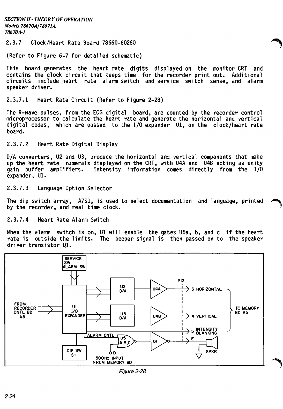
SECTIONII-
Models78670A/78671A
78670A-1
THEORYOF
OPERA
TION
2.3.7
(Refer
This
contains
circuits
speaker
2.3.7.1
The R-wave
Clock/Heart
to
Figure
board
the
include
driver.
Heart Rate
pulses,
microprocessor
digital
board.
2.3.7.2
D/A
up
gain
expander,
2.3.7.3
codes,
Heart
converters,
the
heart
buffer
Ul.
Language
6-7
generates
clock
heart
to
calculate
which
Rate
U2
rate
amplifiers.
Rate
Board
for
detailed
the
circuit
rate
Circuit
from
the
are
Digital
and U3,
numerals
Option
78660-60260
heart
that
keeps
alarm
(Refer
ECG
digital
the
heart
passed
Display
produce
displayed
Intensity
Selector
schematic)
rate
digits
time
switch
to
Figure 2-28)
board,
rate
to
the
I/O
the
horizontal
on
the
information
for
and
and
generate
expander
CRT,
displayed
the
recorder
service
are
counted
and
vertical
with
comes
the
Ul,
U4A
on
the
print
switch
by
the
horizontal
on
the
components
and
directly
monitor
out.
sense,
recorder
clock/heart
U4B
acting
Additional
and
and
from
CRT
alarm
control
vertical
that
as
the
•^k
and
rate
make
unity
I/O
The
dip
by
the
2.3.7.4
When
rate
driver
FROM
RECORDER
CNTL
A8
switch
recorder,
Heart
the
alarm
is
outside
transistor
BD
£
array,
and
Rate
switch
the
Ql.
SERVICE
SW
ALARM
EXPANDER
A7S1,
real
Alarm
is
limits.
SW
/
vv
Ul
I/O
DIP
SW
SI
time
Switch
on,
ALARM
FROM
is
?
£
500Hz
used
clock.
Ul
The
CNTL
MEMORY
will
beeper
INPUT
to
enable
U2
D/A
U3
D/A
BD
select
signal
documentation
the
gates
is
U5a,
then
PI2
and
b,
passed
-> 3
HORIZONTAL
-> 4
VERTICAL
INTENSITY
"^ 5
BLANKING
E
JL
language,
and
c
on
to
NG
^y\
SPKR
if
the
~\
>
printed
the
speaker
TO
MEMORY
BD
A5
^%
heart
2-24
Figure
2-28
Page 56

SECTIONII- THEOR YOFOPERA
Models 78670A/786
78670A-1
T10N
71A
2.3.7.5
U7
is
months,
recorder
power
up
updates
software.
The
chip
FROM
RECORDER
*
60
A3
Clock
a
CMOS
days,
control
and
the
select
U6
I/O
EXPANDER
Circuit
calendar/clock
hours,
minutes
microprocessor.
once
recorder
each
signal
control
callsupUl
CLOCK
(Refer
hour
on
DISABLE
to
Figure
integrated
and
seconds,
This
the
hour
2-29)
circuit.
data
when
microprocessor
or
U6.
To
Q—
and
is
the
read
passed
keeps
This
supplies
on
instrument
track
the
clock,U6is
circuit
this
to
the
power
of
keeps
track
information
recorder
is
on.
time
and
selected.
S^JH-
to
the
board
Between
date
-> H
SLEEP
-)lOVRAW
of
on
in
U6
then
high
R28
its
and
for
will
outputsalow
approximately
and
C18.
output
U6
to
data
be
high
The+input
goes
the
recorder
input
or
approximately20msec
100
high
output
on
pin
22,
msec
later,
of
U8
enabling
control
(time
A
B
c
Figure2-29
the
(a
the
clock
having
CMOS
comparator)
clock
been
chip.
microprocessor
set
or
read).
(Figure
+ 5
0
^^\
inn
m^
P \
Figure
2-30
disable
line.
delayed2times
then
This
signal
telling
Duringaclock
2-30).
+ 5
0
+
2.6V
0
•—
20
mS
it
is
The
the
at
is
that
read
collector
time
about
fed
the
2.6
back
clock
the
outputofU8
of
Q2
goes
constant
volts,
through
is
ready
of
and
Q6
The
clock
pins
1,2,
shifted
pin
8.
and
in
accepts
3.
on
pin6(time
parallel
The
commands
commands
set)
and
are
over
strobed
out
three
in
on
pin9(time
lines,
by
pulses
C2,C1,
on
read).
pin
The
and
CO.
4.
The
shift
These
data
clock
is
are
are
on
2-25
Page 57

SECTION
Models 78670A178671A
78670A-1
The
II -
THEORYOF
clock's
OPERA
oscillator
TION
frequency can be
checked
at
test
point TPl,
which
should be 1
2048.00 Hz. 7
Onaread
(See
C2
1 1 0
Oil
0 0 1
0 0 0
cycle
figure
CI
CO
(time
2-31)
TP=2048
time
register
register
DATA
read)
read
there
Hz
shift
hold
1 1 1 1 1
STB
o 1 1 1 1
C2 |
iJ
CO
CLK
O
1
OUT
O
1
DATA
IN
are
i |
i
four
test
time
shift
allows
holds
i
gnored
commands
point
is
parallel
frequency
executed:
set
loaded
into
register
shifting
shift
out
of
register,shift
data
clock
~|
40
PULSES
nnnnnnnnnnnnn
u uu uuu miss?-™
internal
Onawrite
C2
CI
0 0 1
0
0 0 0
10
(time
CO
set)
register
time
register
DATA
cycle
set
STB
C2
O j
CI i
CO
O '
CLK
OUT
O
DATA
IN
0
there
shift
hold
1 (—
1
i !
1
1
1
Figure 2-31
are
three
allows
new
loaded
holds
shifting
time
into
shift
commands
/date
ignored
40
PULSES
nnnnnnnnnnnnn
| | | | | 11|
||
| | [| [ |||DATA
||
executed: See
in
information
internal
register,
DATA
OUT
IGNORED
SHIFTED
IN
of
counters
"L
new
shift
data
is
clock
figure
parallel
2-32
2-26
Figure
2-32
Page 58

SECTIONII- THEOR YOFOPERA
Models78670A178671A
78670A-2
TION
Afterawrite
pushing
be checked.
2.3.7.6
U9
isaprecision
volt
reference
the
Voltage
fractionofthe
This
current
the nickel-cadmium
The
Clock/Heart
2.3.7.7
it
keeps
reference
drain
Clock
clock
chip,
Rate
time
is
when
microamperes,sothe
2.3.7.8 Clock Protection
A
low
on
the
sleep
clock
during
the
cycle
PUSH
Reference
TO
temperature
voltagetothe
+5
volt
operatesatall
about1milliampere,
battery.
Battery
U7,
Board.
is
those
battery
line
defibrilator
is
finishedaread
MARK
button
compensated
comparator
supply
to
times
powered
Since
sources
causes
the
life
are
should
the
discharge
cycle
the
new
time
voltage
U8.
detect
from
by
clock
power
unswitched
which
a
small
is
is
independentofexternal
removed.
equal
collectorofQ2
(Figure
is
and
regulator
This
failure
less
than
battery
The
clock
the
rated
2-29).
executed.
date
can
which
By
furnishesa2.490
referenceiscompared
and
raw
to
disable
system
the
self
which
chip
current
shelf
go
low
battery
discharge
is
located
life
of
which
the the
power.
power
is
the
disables
with
a
clock.
The
rate
of
on
the
sources,
onlyafew
battery.
the
2.3.7.9
A
quartz
Typical
over
the
temperature,
2.3.8
Clock
crystal,
accuracy
temperature
accuracy
Recorder
(RefertoFigure
This
display
The
the
board
heat
control,
2.3.8.1
ECG
composed
recorder
amplifier
passed
(see
controls
of
heart
ECG
signal
of
U5a,
is
turned
Figure
ECG
Monitor
is
Crystal
operating
of
the
Control
6-8
for
the
rate.
signal
to
the
R10,
off,
reduced
2-33).
at
clock
range
is
about5minutes
Board
is5minutes
of
0 to
78670-60200
detailed
operation
The
recorder
amplitude
to
Recorder
recorder
and
Rll.
the
to a
To
signal
very
32.768
50
KHz,
degree
per
schematic)
of
the
functions
limiting
Signal
is
bufferedbya
prevent
is
switched
small
maintains
per
month,
C.
year.
recorder,
include
and
switching,
the
recorder
by
value
(<<1)
the
accuracy
plus
Atareasonably
annotation,
chart
unity
stylus
Q5.
When
and
adjustment
and
drive
and
print
gain
essentially
inverting
from
Q5
is
of
the
clock.
tolerance
constant
calculation
motor
head
and
sylus
drive.
amplifier
moving
on
the
no
when
gain
signal
room
and
the
of
is
2.3.8.2
The
ECG
2.56
volts.
CR12,
signal
R43,
ECG
and
Memory
from
This
R44
to
the
is
cancelled
(figure
Recorder
memory
board
2-33).
Signal
to
the
to
approximately
recorder
zero
board
by
the
has
a DC
offset
circuit
of
about
consisting
of
2-27
Page 59

SECTION
Models 78670AJ78671A
78670A-1
II -
THEORYOF
OPERA
TION
2.3.8.3
The
recorder
1.
A
high
(0
volts)
through
2.3.8.4
A
high
(+BAT)
signal
on
circuitry.
transmission.Alow
and
Q5
Recorder
here
turns
Q3
and
chart
Movement
movement
(>2.5
them
Q4.
Recorder/Signal
at
the
off,
allowing
ECG
and
Stylus
and
stylus
volts)
on.
turns
These
Control
collectorofQ4
(-5
volts)atthe
signal
to
(^CRI2
-I2V
R43
-wv-
RM
IN
56V
R44
-vw-
Heat
heat
the
chart
signals
turns
pass
through
U5A
RIO
Q5
®
CR7
-W-
Control
are
drive
are
the
recorder
collector
R42
SW
BAT
controlledbya
and
stylus
controlled
to
the
ECG TO
RECORDER
by
off,
and
of
Q4,
recorder
signal
heat
off,
at
edge
andalow
microprocessor
Q5
on,
to
turns
the
stylus
recorder
deflection
pin
Ul,
prevent
2.3.8.5
To
prevent
active
This
Ql
than
limiting
circuit
and
approximately
negative
of
this
prevent
ECG
Signal
excess
is
Q2
are
feedback
is
to
limit
reverse
TO
RECORDER
Ampltude
power
circuit
composed
biased
+ or -
and
the
bias
breakdown
ECG SIGNAL Rl
IN
CR8
Limiting
consumption
is
employed
of
Q1,Q2,CR2,CR3,
off.
However,
2.1
volts,
reducing
output
+
I2V
-I2V
Figure
in
Ql
the
gainofthe
signal
of
the
Q4
and
the
to
when
>R\A
RI7
f_Q3
a/w
•
2-33
Switching
recorder
prevent
and
R4
the
or
Q2
turns
7<^\
V
output
amplifier
excursion
base-emitter
•RI3
Ul
19
deflection
!ECR5
R4|
-vw-
stylus
overdriveofthe
through
R9.
signal
on,
drastically
excursion
(Figure
to + or -
junctions
ECG
OUT
TO
RECORDER
2.1
of Ql
In
normal
2-34).
volts.
and
circuits,
recorder
operation,
is
greater
increasing
The
CR2
and
Q2.
an
input.
the
effect
CR3
2-28
Figure
2-34
Page 60

SECTIONII-
THEORYOF
Models 78670Aj78671A
OPERA
78670A-1
TION
2.3.8.6
A
defibrillatorisa
the
recorder
circuit
oscillator
Microprocessor
defibrillating
control
known
asa"tickle"
which
microprocessor.
microprocessor
circuit
This
2-35).
(figure
will
circuit
The
2-36).
non-inverting
to
forceareset
consist
circuit
input,
Reset
very
pulse
microprocessor
is
retriggeredatperiodic
If
noise
retrigger
of
U5b,
operation
The
two
and
the
+
-I2V
-I2vJ L
TICKLE
PULSE
IN
(Tickle)
high
and
the
or
"heartbeat"
causes
the
of the
series
third
5V
R24
noise
associated
operation
circuit,
recorder
Q6,
Q7
is
similar
gates
gate
R36
WV
€
Circuit
environment.
high
to
be
circuit
intervals
program
disruption
after
control
and
associated
to
that
are
simulatedbythe
by
Q6
operating
1)
JCR4
R22
W.
07
R23
•
WV
CRII
-w-
The
noise
voltage
disrupted.
is
used.
byasoftware
and
20
to
25
milliseconds
microprocessor.
passive
of
the
as
an
R26
?R27
R20
it—<WV
•
+
5V
impulses
relays
To
It
isaretriggerable
produced
can
cause
prevent
routineinthe
the
failure
the
components
three
op-amp
gate
U5b
inverting
SLEEP
oscillator
amplifier.
this,
of
tickle
(figure
using
by
the
a
the
its
When
allowed
circuit
(figure
to
free
run
producesaseries
2-37)
1111
withaperiod
1111
1 1
1111
(no
of
negative
of
12V
Figure
Figure
retrigger
going
20
to
25
RESET
MICROPROCESSOR
PULSE
2-35
2-36
signal
from
pulses
approximately1millisecond
milliseconds.
VERT.
HORIZ.
TO
Ul
microprocessor)
1.0
V/Div.
5
ms/Div.
the
"tickle"
wide
Figure
2-37
2-29
Page 61

SECTIONII-
Models
78670A-l
To
"tickle"orretrigger
by
the
(collectorofQ6)
16
milliseconds
Cll
terminal
Q8
allows
recorder
discharge
THEORYOF
78670Ap8671A
OPERA
TION
the
microprocessor
to
during
Ul,
a
high
normal
which
forcesareset,onpoweringupthe
of
U5b,
an
control
for
forcing
external
signal
microprocessor
additional
its
noise
circuit,apulse
turnsonQ7,
or
non-reset
operation
state.
of
the
instrument,bypulling
output
from
high
and
the
defib
and
put
protection.
about1millisecond
charges
These
instrument.
CIO,
pulses
and
downonthe
turning
control
it
to
on
Q6.
microprocessor
"sleep"
during
wide
forces
are
generated
is
generated
the
output
every
inverting
to
reset
defibrillator
the
2.3.8.7 Print
The
printhead
resistance
inserts
The
intoaconnector
common
protective
each
resistor
2-38).
gates
U2
are
Head
consists
of
87.5
ohms.
terminal
circuitry.
to
heat
is
driven
tied
together
Driver
in
consistingofC1,R1,R2,
the
printhead
from
being
in
the
event
R2
and
R3.
enabled
foralength
combination
edges.
Rl
drive
enabled
signals
longer
ofamicroprocessor
A
negative
of
of
R2
and
is
to
limit
MICROPROCESSOR
of
7
The
(J30)onthe
is
connected
The
Darlington
it
and
turn
to
R3,
and
coming
than
going
time
R3.
controlledbythe
The
capacitive
CMOS
£>
resistors
printhead
is
the
to
transistor
produceadot
by
CMOS
gatesU3and
the
output
CR1.
3-5
The
from
Ul.
milliseconds.
failure.
edge
diode
at
pin
allows
current.
GATES
with
one
bonded
recorder
the
positive
on
of
the
seven
The
The
11
of
time
quick
DARLINGTON
ARRAY
common
to a
flex
control
array
thermally
U4.
eighth
gates
RCD
network
This
inputs
U4
are
causes
constant
charging
THERMAL
PRINTHEAD
—o—wv—i
-(MMrHi
terminal,
cable
board.
volt
U2
power
sinks
sensitive
One
input
gate
act
as
prevents
is
to
protect
biased
the
of
of
one
of
through
signal
up
seven
CI
and
CI
on
and
a
end
supply
current
paper
each
a
switches
the
printhead
the
printhead
to +4
gates
the
positive
nominal
of
which
through
through
(figure
of
seven
network
for
volts
to
by
be
parallel
going
The
above)
The
2-30
output
drive
pin 11
signal
to
U3
Ul
f—-
2LXR4
+5V
PRINTHEAD
PROTECTION
NETWORK
QIO
TO
+I5V
the
Q9,
"tickle"
circuit
(see
of
U2
U4
is
V1
also
shown
U4
£>
drives
in
Rl
-K-
CI
I—•
TO Q7 AND TICKLE CKT
Figure
Figure
Q7
2-38
to
2-39.
R3
:R2
retrigger
Page 62

SECTIONII-
THEORYOF
Models 78670A178671A
OPERA
78670A-1
TION
2.3.8.8
Q9,
QIO
down
transients.
C21
slowly
to
the
CR15,
which
voltage
h
++++
•ffH
Print Head Protective Circuit
and
associated
charges
print
head.
forms
turns
off
fH4
4+H
On
through
a
Q9
CRI5
H-H :i+H
components
power
up,
R47
On
power
capacitive
and
QIO,
+
5V
33/xF'
R46
51.1K
n?
C20
Hff
C21
until
down,
removing
r\
•+++
Figure
protect
clamps
Q9
the
voltage
voltage
2-39
the
the
turns
+5
divider
print
Q9
on
volts
from
.QIO
VERT.
HORIZ.
base
which
decays
of
the
I
5
PRINT
HEAD
head
to
turns
C20
print
PM
C22
330/xF
1.0
5
from
-12
volts,
on
rapidly,
and
head
+
I5V
TO
PRINTHEAD
DRIVER
U2
V/Div.
ms/Div.
power
QIO,
C21.
up
holding
applying
forward
This
(Figure
and
power
it
off.
power
biasing
decaying
2-40).
2.3.8.9
See
the
detail
Ul
lines
P10
Information
signal
message
PROG,
from
is
P20
expanders,
the
I/O
expanders
The
16
millisecond
printing
The
R-wave
and
calculates
The TAP
For
maximum
The
tells
line
ewery
of 60 seconds.
MARK
Ul
line
to
Input/Output
schematic
thru
to
the
available.
through
Ul
and
P13
be
printed
defib
P23
U6,
is
selected.
line
the CRT
line
heart
(Ul,
time
(Ul,
run
the
the
display.
comes
rate
pin
switch
pin
recorder
Lines
(Figure
(pins27thru
is
passed
control
(Ul,
on
comes
from
which
33)
32)
board
lines
the
clock
from
the
is
printed
goes
is
actuated
goestothe
and
♦
-I2V
Figure
6-8)
for
to
generates
21
board.
the
ECG
digital
to
the
print
2-40
the
following
30)
go
to
the
Ul
over
through
The
memory
these
an
interrupt
25)
chip
board
board.
and
displayed
PUSH
8
SEC
the
recorder
PUSHTOMARK
a
down
arrow
circuits.
defibrillator
lines.
which
communicate
select
and
Ul
on the
RUN
switch
will
switch.
and
line
is
used
counts
CRT.
on
run
Closureofthis
the
time/date
control
The
data
available
signalsUlthat
with
to
R-wave
8
the
controls
synchronize
pulses
the
front
seconds
two
which
up
information.
board.
a
I/O
of
the
and
panel.
to
a
switch
2-31
Page 63
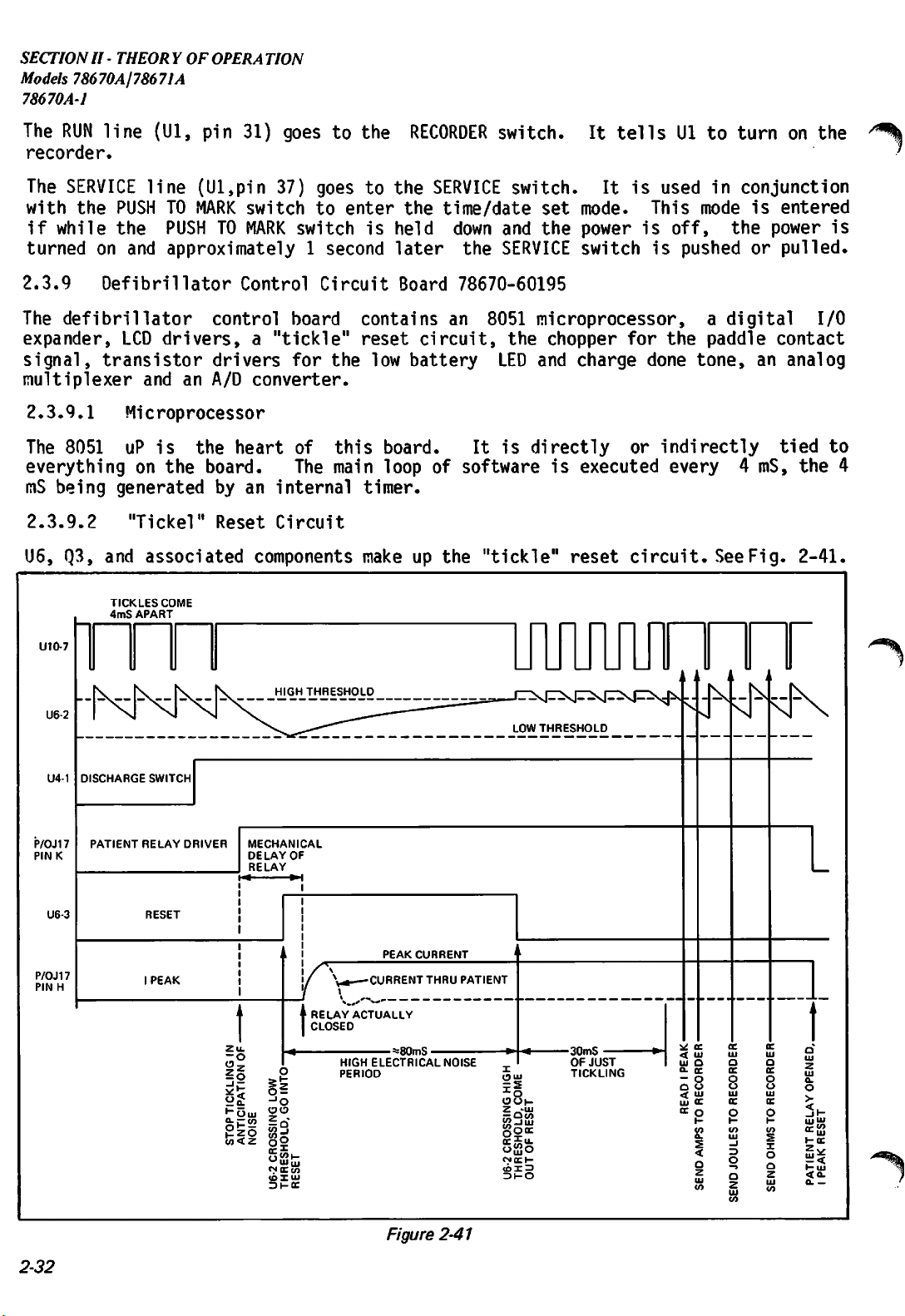
SECTION
II -
THEORYOF
OPERA
TION
Models 78670A/78671A
78670A-1
The
RUN
recorder.
The
SERVICE
with
the
if
while
turned
on
line
PUSH
the
and
(Ul,
pin
line
TO
PUSH
31) goes
(Ul,pin
MARK
TO
switch
MARK
37)
to
goes
to
switch
approximately1second
the
to
enter
is
RECORDER
the
SERVICE
the
time/date
held
later
down
the
switch.
switch.
set
and
the
SERVICE
2.3.9 Defibrillator Control Circuit Board 78670-60195
The
defibrillator
expander,
signal,
transistor
multiplexer
LCD
and
control
board
drivers,a"tickle"
an
A/D
drivers
for
the
converter.
contains
reset
low
circuit,
battery
an
8051
microprocessor,
the
chopper
LED
and
It
tells
It
mode.
power
switch
charge
is
is
for
used
This
off,
is
the
done
Ul
to
in
mode
pushed
a
paddle
tone,
turn
on
the
conjunction
is
entered
the
power
or
pulled.
digital
I/O
contact
an
analog
is
/19%
I
2.3.9.1
The
8051
everythingonthe
mS
being
Microprocessor
uP
is
the
heart
board.
generated
by an
of
The
internal
2.3.9.2 "Tickel" Reset Circuit
U6,
Q3,
and
UIO-7
U6-2
U4-1
P/OJ17
PINK
TICKLES
4mS
DISCHARGE
PATIENT
associated
COME
APART
SWITCH
RELAY
DRIVER
components
MECHANICAL
DELAY
OF
RELAY
this
main
timer.
make
board.
loop
of
up
It
is
directly
softwareisexecuted
the
"tickle"
reset
or
indirectly
every
circuit.
n n n
See
4
Fig.
mS,
ii
tied
the
2-41.
to
4
2-32
U6-3
P/OJ17
PIN
RESET
PEAK
CURRENT
ACTUALLY
HIGH
PERIOD
•CURRENT
ELECTRICAL
I
H
PEAK
Zu.
-o
So
•"DLL!
"ZO
II
->o
Is*
o">i-
wocco
(OXLU
31-oc
RELAY
CLOSED
O
•=*80mS-
Figure
THRU
NOISE
2-41
PATIENT
UJ
S
o
O CO
-ILL)
Ooc
III.
wO
OCI-
13
HO
•30mS
OF
JUST
TICKLING
<
LU U
CL fC
- O
o o
< LU
LU CC
<r o
Page 64

SECTIONII-
U6
is
configured
80-100
delivered
noise
propram
When
tickling,
mS,
spikes
address
the
if
from
uP
and
interference,
reset,
to reset
2.3.9.3 LCD drivers and recorder data
U7,
out
strobe the data into the LCD drivers. If information is to be sent to the recorder
board,
ready.
inverted
U8
by
the
the
and
the
the
Since
for
I/O
U9
DATA
as
a
free
not
inhibited.
PI.6
upset
location
closes
U6
thus
(U10,
the
the
will
then
increasing
expander
recorder uP on
are
CMOS
uP
port0bits
AVAILABLE*
inverter
the
recorder
running
Pin
uP
so
0.
high
hold
(U4)
is
the
BCD
to 7
0-3
signal
buffers
uP
oscillator
When
the
uP
7)
every4mS
as
to
reset
voltage
the
the
also
recorder board.
relays,
uP
in
immunity
de-selected
segments
(UIO,
are
whenever
is
pins
used
used
DATA
which
is
running properly,a"tickle"
to
the
it
reset
of
internal
would
reset
preventU6from
uP
and
start
has
also
for
the
durationofhigh
registers.
and
U5F
will
latch/decoder/drivers.
36-39).
to
(U5A,
AVAILABLE*
Port1bits
inform
B,
the
C,
recorder
and
is
THEORYOF
Models 78670A/78671A
the
oscillating.
it
running
been
programmed
When
sendasleep*
BCD
0-2
uP
D),
the
low.
See
OPERA
78670A-1
uP
once
pulse
again
to
electrical
the
signal
data
are
(UIO,pins
that
BCD
Fig.
data
data
2-42for
TION
every
is
If
at
stop
uP
is
put
1-3)
is
are
timing.
P0.0-P0.3
DATA
P1.3
DATA
AVAILABLE
P1.2
LCD
STB
P1.1
LCD1
STB
P1.0
LCDO
STB
INVERTED
CODE
2
100's
INVERTED
100's
10's
INVERTED
NTs
Vs
INVERTED
1's
Figure
2-42
2-33
Page 65

SECTIONII-
Models
78670A\78671A
78670A-l
THEORYOF
OPERA
TION
2.3.9.4
U12
is
an
select
A/D
After
from
The
the
The
multiplexer
the
by
level
R30.
2.3.9.5
The
expanded
4
read
the
to/from
the
converter.
an
UIO
pin
uP
services
interrupt
bus
is
analog
P2.3
of
shifter
R53,
I/O
expander,
ports
instructions
from
falling
U4 on the
Analog
8 to 1
analog
analog
16.
request
normally
and
A/D
signal
the
uP
so
R64,
I/O
Expander
are
that
port.
edgeofa
Multiplexer
analog
signal
R37
and
signal
When
the
this
interruptbysendingaRD*
and
in
tri-state
converter,
is
low
(UIO,
that
CR12,
U4,
in
and
expands
and
multiplexer.
to
be
sampled.
C18
set
the
is
selected,
conversion
brings
serves
and
Q5
is
pin
24).
the
high
CR13
protect
the
A/D
Converter
clock
the8bits
except
off,
UlA
state,
number
labelledP4throughP7and
it
recognizes;
An
instruction
rising
strobe,
edge.
write
and
PI.7
port
of
P2.0
-
Ull
is
speed
A/D
conversion
is
completed,
of
when
asaunity
as
is
the
U13B
to
a 4x
an
of
RD*
open
gate
and
I/O
port,
selection
the
uP
P2.2
an
for
signal
data
is
gain
gain
drain
of
Ull
lines
each
(UIO,
of
the
8
bit
the
converter
is
initiated
an
interrupt
(UIO,
to
the
low.
buffer
stage.
CMOS
Q5
can
from
over-current.
which
portis4
OR
with
from
uP
pin
uP
(UIO,
successive
at
by a WR*
is
pin
17),
bus
U13B,
The
buffer
be
port,
are
8);
placed
when
gain
pulled
the
bits
AND
latched
data
of
Q5
which
uP
wide.
pins
21-23)
approximation
about
issued
the
up to
300
by
which
converter.
between
is
on,
is
controlled
acts
+12V
kHz.
signal
Ull.
clears
or,
as
controls.
There
with
port,
into
is
transferred
U4
the
if
a
by
The
are
and
on
P4-P6
and
from
(ie,
pockets.
the
2.3.9.6
The
associated
I/O
are
input
R-wave
the
from
charge
50Jinterlock),
P6
reads
CHARGE
safety
DONE
Relay
and
R's
port
and
their
discharge,itis
that
10K
most
ohm
of
the
safety
simultaneously.
hardware
2.3.9.7
Q2,
is
showninFig.
the tone
of
which
R24,
(R23,
Cll
sounds
emphasize
C16,
Charge
and
ports;
the
switch,
LED,
drivers
patient
and
P7
ECG
DIGITAL
and
the
binary
patient
relay
C's,
is
discharge
the
relay
are
only
respective
desirabletohave
energy
resistor.
After
Done Tone
CR3
2-43.
different
the
and
form
The
the
is
dissipated
The
commands
CMOS
inputofU1E)
the
fundamental
from the
harmonics
output.
board
switches,
reed
switch
position
driver
drivers
the
transistor
the
commands
speaker
R-wave
of
roughly
P4
senses
(RSYNC*)
internal/
which
of
the
and
safety
on
this
intermediate
driver
safety
into
from
are
relay
the
the
given,
which
driver.
frequency
tone or the heart
500
the
for
conversion.
senses
energy
board,
stages
on
lag
patient
uP
to
the
uP
delays
The
signal
is
250
Hz.
front
panel
SYNC/DEFIB
P5
external*
when
select
relay
the
switch.
driver.
paddle
paddles
composedofU1D,
between
the
HV
CHARGER
behind
and
close
is
the
Hz.
the
patient
virtually
both
reset
and
safety
going
to
Therefore,tothe
rate
takes
P7
U1E,
the
controlling
board.
none
relays
it
must
relay.
the
alarm
switch
the
input
selection
are
in
the
controls
Ql
and
relay
into
the
are
given
be
the
base
of
ear,
tone,
both
At
so
Q2
2.3.9.8
Q4
sinks
on
continuously
low
(SwBatt2is
with
2-34
a 1
Battery
the
BATTERY
second
LED
with
sensed
signal
driver
LED
base
by
of
current.
current
uP)
and
33%
duty
When
being
is
cycle.
the
battery
supplied
not
being
is
being
through
charged,
R28.
the
charged,
When
the
uP
flashes
Q4
is
battery
Q4
turned
via
CR5
is
Page 66

SECTIONII - THEORY OFOPERATION
LED
NO.
10
THRESHOLD
Models
78670AJ78671A
78670A-1
2.3.9.9
The
paddle"
indicates
means
and
ampliff
display
stable.
Here's
lower
loc
how
^ASE2
F
CASE 2 LED NO. 7
ON
TIME
"=-
CASE1
ON
LED
TIME
NO.
—
LED
NO.9THRESHOLD
LED
NO.8THRESHOLD
LED
NO.7THRESHOLD
LED
NO.6THRESHOLD
^-
71
LED
NO.5THRESHOLD
LED
NO.4THRESHOLD
LED
NO.3THRESHOLD
LED
NO.2THRESHOLD
A
very
sh(
discharges
through
chopped
R4<
vo
comparators
up
only
a smal1 ch
one
display
on
whole
ha
c.
n
AA
F,9ure2-44
LED
NO.1THRESHOLD
Page 67

SECTIONII-
THEORYOF
Models78670A/78671A
OPERA
78670A-2
TION
2.3.9.10
Figure
the
capacitorisbeing
the
HV
same
time,
same
the
of
of
amount
signal
the
these
Monitoring
2-45
showsasimplified
charger
U1D
from
same
two
board,
increasesinvoltage
(but
with
U1C
so
polarity
signals
the HV
capacitor
schematicofthe
charged,
will
keep
referenceto5.4
that,atthe
and
increasing
will
indicate
capacitorisimbalancedbysome
FROM
FLYBACK
TRANSFORMER
24.9M
-VW-
32
HV
5.4V
uF
<
CAP
HV
capacitor
the
current
the
capacitor
flowing
balanced
(referencedtoground)
volts).Onthe
inputtothe
with
stray
respecttoground.
the
voltage
resistancetogroundonone
monitoring
through
the
around
and
control
multiplexer,
Thus
on
the
capacitor,
R72
|—VVV»-+
^L Q
V
circuit.
24.9M
2.7
U1C
board,
both
resistors
volts.
decreasesbythe
U13A
signals
the
numerical
even
side.
+
2.5V
2.!
Energy
Adj
8TOI
MUX
UI2
At
the
inverts
will
sum
if
the
TO
A/D
CONVERTER
As
on
be
Energy
tolerance.
2.3.9.11
A
defibrillation
(a
high
the
SHUTDOWN
close
Adjust
Charge
and
charger
will
to
the
then
24.9M
—VW—*—\y^
> I
*STRAY
V
Pot
and
episode
lowatU4
circuit.
go
high
set
value
V
HV
CHARGER
UID^>
>^
36
K
vvv
BOARD
(R72)isan
Discharge
is
initiatedbypressing
pin
When
and
as
the
will
possible.
\
'
Figure
adjustment
Cycle
22).
capacitor
periodicallygolow
The
If
2-45
madetocorrect
uP
then
voltage
the
energy
CONTROL
and
reads
to
select
BOARD
for
releasing
the
(UIO
reaches
keep
the
switch
the
pin
its
HV
the
charge
6)
lowtostart
selected
capacitor
is
changed
capacitor
switch
value,
voltage
as
before
2-37
Page 68

SECTION
Models78670Aj78671A
78670A-l
the
capacitor
II -
THEORYOF
OPERA
capacitorisdischarged,
into
the
safety
TION
the
resistorifnecessary.
uP
will
charge
to
the
new
setting,
dumping
the
When
activated.
looks
pressed
relay
wait
cardioversion
2.3.9.12 Cardioversion
For
except
The
momentarily
sensed
monitor
LEADS/PADDLES*
uP
uP
panelisturnedonby
mS
2.3.9.13
the
for
proper
The
a
high
capacitor
charge
on
simultaneously.
driver
for
cardioversion,
the
sync
by
tells
the
respondsbypulling
and
the
reset
relay
mode
grounds
the
is
picking
ECG
LED
Software
and
turn
as
or
synchronized
everythinginthe
drivers
is
selected
SYNC
uP
through
signal
DIGITAL
is
turned
Safety
U4
up
from
U1F.
voltageisreached,
done
LED
pin
1.
When
the
off
the
safety
described
defibrillation.
now
are
or
de-selectedbya
ON*
or
DEFIB
U4
pins2and
the
board
RSYNC*
off
ECG
the
ECG
of
high.
On
each
for
Features
is
turnedon(U4
A
high
means
both
highisdetected,
relay
in
Section
charge
closed
ON*
3.
from
ANALOG
sync
mode
When
detected
that time
driver
2.3.9.2.
and
only
onahigh
respectively.
Sync
board
mode
leads
comes
through
RSYNC*ishigh,
R-wave,
period.
the
pin
charge
13
goes
discharge
theuPwill
(i.e.,
The
discharge
to
low
switch
instead
may
to
SYNC
on
This
not
the
EN*
the
RSYNC*
done
low),
switches
turnonthe
close
only
sequence
tone
and
both
will
the
have
patient
relays)
exception
is
the
transitionofRSYNC*.
the
be
of
uP
(UIO
goes
front
switch
selected
the
at
UIO
pin
sync
LED
low
panel
information
unless
paddles.
pin
27.
25).
on
for
The
the
about
uP
now
been
and
same
which
the
This
The
ECG
front
200
be
is
is
The software in the uP
disable
the
safety
voltages
2.3.10
(RefertoFigure
2.3.10.1
This
1.
2.
3.
4.
5.
the
charge
and
problemsitlooks
relay
failed
out
of
Defibrillator
to
specifications.
6-11
General
section
Defibrillator
HV
defibrillator
HV
defibrillator
HV
patient
Discharge
describes
paddle
relay
current
inverter
energy
and
monitors
discharge
for
are:
for
cycleifan
overcharge,HVcapacitor
openorclose,
High
for
transformer
Voltage
detailed
the
following:
set,
storage
drive
with
power
circuit.
certain
arc
in
Section
schematic)
CHARGE
supply
capacitor.
and
and
PCB
sample/hold
failures
unsafe
conditionisdetected.
patient
DISCHARGE
78670-60120.
circuit.
in the HV cirucits and
Some
grounded,
relay,
switch.
and
leaky
capacitor,
certain
reference
will
of
6.
7.
2-38
HV
safety
Voltage
relay
reference/low
and
drive
circuit.
battery
shutdown
circuit.
Page 69

SECTION
II -
THEORYOF
Models 78670A/78671A
OPERA
78670A-1
TION
2.3.10.2
The
HV
battery,
Power
supplying
circuit.
battery
(J48)
flow
lighting
present.
Switched
circuits.
NOTE: Power connects to Tl via A11F1 at all
Power
Base
2.3.11
U3
is
an
for
power
Power
defibrillator
Power
Base
V-REG
CR114
to
all
of
voltage
are
Pulse
I.C.
to
oscillator
internal
ensuring
comparator
the
Circuits
Base
at J45
to the
guarantees
power
through
the
front
Vc,
removed
Width
Pulse
I.C.
inverter
and
the
through
mother
Kl
circuits.
CR9
and
panel
returns
or
A11F1
Modulator
Width
Modulator
circuits,
PCB
mother
J48.
PCB and
coil
C17
R129
to
BATTERY
to
open.
(Figure
with
contains
PCB.
V-REG
dropout
and
the
LED
this
(PWM),
pin16for
frequencyatabout8kHz.
and
gatingtothe
output
transistors
are
never
power
The
battery
from
V-RAW
C19
to the HV
for
Power
suppress
battery.
if
both
PCB
via
2-46)
includinga+5
external
This
internal
bothonat
suppliesasawtooth
flip-flop,
circuit
connects
the
Power
Base
noise.
The
charging
J19,
pin
times,
the
Base
flyback
AC
loss,
Battery
Q22
voltage
17,
unless
volt
use.
which
same
wiring,
to
between
J43
and
closes
transformer/drive
reconnecting
relay
charge
circuit
for
and
both
gives
battery
all
battery
low
regulator
Cll
and
R31
drivetothe
enables
time.
the
the
J44;
the
Kl,
the
current
steady
are
level
and
circuit
set
the
gates,
The
other
and
3.5
on
pin9;(2)
pulls
circuit,
comparator
volt
maximum).
above
the
rises
input,
The
applyingapositive
pin2referenceof2.5
above
the
voltage,togiveanominal
R27
"cO^i—Hi
+
5V
REF
OUT
o
TP9
<§>•
R26
IOK
^jtLsy—^L__p>
R25
IOK
LIMIT
OUTPUT
HV
i
I
CR4
—14-
Error
pin9,controls
output
can
be
voltagetopin
nominal
90%
V
REG
Amp
200
maximum
^'^
15
-*•
+5V
SHUTDOWN
INPUTS
millivolt
duty
-I-.OI
AAAA^
COMPARATOR
the
duty
reducedorshut
10;
volts,or(4)
cutoff.
cycle.
r
Cll
<R3I
>I4
Jri
7K
_NC
let
OSC
^C>
CURRENT
LIMIT
U3
SELECT
cycle,
(nominal
downby(1)
(3)ifpin1,error
if
pin
4,
CR4
JT^LTlN
3524
limits
vc
On?
Tb
pin9maximum
OUTPUT
f—jmruL
FLYBACK
DRIVE
CURRENT
LIMIT
1.0
volt
pulling
down
amplifier,
current
limit
off
Figure
2-46
2-39
Page 70

SECTIONII-
Models 78670A/78671A
78670A-2
THEORYOF
OPERA
TION
2.3.11.1
This
Pin
circuit
8,
circuit
up
with
ground
for
guaranteed
2.3.11.2
The
defibrillatorHVcapacitor
CHARGE
microprocessor
provide
9
through
1/3
second-important
during
CR112
activated,
Start.
of
Q9.
PWM
Shutdown
acts
J19
connects
when
not
current
through
switch
the
minimum
Soft
S10,
sufficient
CR111
the
OFF
normally
but
The
Low
as
charging
flowing
Schottky
Start
which
clamps
drop
and
part
of
gives
will
Battery
to
R121
(Figure
a
soft-start
UIO,
pin6in
the
from
Vc
diode
cutoff
connects+5Vto
the
voltage
to
assureQ9turnoff.
to
charge
for
accurate
the
duty
enough
operate
Shutdown
2-47)
ON/OFF
switch
the
Defibrillator
defibrillator
through
CR111,
voltage
charge
R48,
keeping
of
0.7V.
cycle
the
at
pin
8,
C105,
low
energy
cycle,
drop
if
the
circuit
so
Q9
while
the
circuit
inhibits
for
the
PWM,
Control
capacitor,
CR13
and
U3
is
started
defibrillator
J19
to
COMP
so
CRll.
shut
down.
by
control
about
0.5
current
givingastartup
selections.
under
shutdown
current
circuit,
open
circuits,
charge
by
U3,
PCB.
the
base
Q9
clamps
The
pressing
volt.
then
flows
time
C8
inhibits
limit
control.
U3,
pulling
discussed
This
of
Q9
pin
PWM
is
the
APEX
PCB.
The
CR13
from
constant
PWM
pin
but
without
up
on
above.
is
is
pulled
9,
U3
selected
paddle
control
and
U3,
of
about
restart
10
is
the
open
to
CRll
pin
not
Soft
base
2.3.12
TO
TO
DEFIB
CONTROL
BD
AIO
HV
Defibrillator
SHUTDOWN
U3
J19
6f
PIN
ZCRI
LOW
10
SHUTDOWN
>CRII2
;cri3
R48+!?y
•AAA/—<J>
Inverter
FROM
BAT
•RI06
Figure
Circuit
ih
SOFT
+s°v
2-47
START
CI05
t
CRI24
I
fcl
(Figure
TO
COMP
U3
PIN
4
JI5
^3>
2-48)
C8
9
PI5
SIO
CHARGE
L I
APEX
PADDLE
(RIGHT)
This
circuit,
voltage
2-40
to
driven
charge
by
the
Pulse
the
defibrillatorHVcapacitor,
Width
Modulator
Al-Cl.
(U3)
output,
provides
the
high
Page 71

The
PWM
"on"
The
primaryofTl
(or
V/bat)
Q5,
producing
Tl
primary
and
CR100
The
HV
capacitor.
and
tap
define
rectifier
Note
defibrillator
e.g.,
+2.6
kV
drive
switches
thus
the
Tl
primary
the
"flyback"
provides
safe
contains
capacitor
and
voltage
that
-2.6
Q2
on,
in
startsalinear
inductance.
high
voltage
sufficient
HV
metering
two
metering
turn-off
limits
for
approximately
kV
nominal
for
SECTIONII-
turn
current
switching
ramp,
When
U3
discharge
bias
Q2
and
Q5.
on
with
turns
from
off,
the
(across
resistors,arectifier
resistors
midpoint
the
360
define
between
joule
the
the
charge
THEORYOF
Models 78670A178671A
Q5,
through
slope
determinedbyV/raw
Ql
abruptly
secondary
R32
and
C13)
diode
ground
2
point
terminals
condition.
and
OPERA
C13
and
turns
of
Tl.
for
Q5.
noise
for
voltages,
TION
78670A-1
R32.
off
The
CR5
filter
the
HV
The
defibrillatorHVenergy
long-life
self-charge
safety.
CONNECTION
VALUES: KEEP A SHORTING WIRE ON THE TEMRINALS WHEN NOT IN THE CIRCUIT.
The
actual
in
the
seconds
line at 110 to
FROM
polyester
after
The
usual
CAN
OCCUR,
duty
PWM.
withafully
PWM
U3
PINS
It
120
DRIVE
II S 14
cycle,
is
(e.g.,
operation,
failure
WITH
during
adjusted
charged
volts.
storage
"Mylar
and
mode
POSSIBLE
isadead
charging,
by
R34
battery,
CR5,
capacitor
")'
type
must
component.
be
short
short.
REC0NNECTI0N,
is
determinedbythe
,
set
for
or 7
TP2
seconds
TPl
CRIOO
t*x^
(32
uF,
5.5
As
is
circuited
during
HOWEVER,ANOPEN
DURING
a
charge
with
HV
CI6
HANDLING,ATLETHAL
current
time
the
Power
FLYBACK
6
VRAW
TRANSFORMER/RECTIFIER
TJ
kV)
typical,
CIRCUIT
to
360
Base,
m
TO
METERING
is
a
compact,
it
handling,
INTERNAL
ENERGY
limit
+ -
HV
AMPS
circuit
joules
with
i+J 5.5kV
24.9M
the
can
for
of
9
AC
TO
PWM
2.3.12.1
As
the
Inverter
resistors
U1D.
ground,
After
while
CURRENT
LIMIT
PIN
4
rn
HV
Monitor
Circuit
charges
provide
inversionbythese
positive
the
"V-Cap
(Figure
the
defibrillator
drive
2"
to
amplifiers,
output
m
Figure
2-48
2-49)
amplifier
the
will
drop
R35
capacitor,
U1C
and
"V-Cap
below
the
the
24.9
negative
1"
output
noise
M
ohm
drive
to
will
filtered
metering
amplifier
rise
above
(R140,c4)
2-41
Page 72

SECTIONII-
Models78670A\78671A
78670A-l
THEORYOF
OPERA
TION
55.4VRef.
the
defibrillator
where
The
preset
divided
pin
1,
V-CAP
MOTHER-io^-
BDGND. N
V-CAP174"
error
these
energy
rises
1 12^-
amplifier
output
as
the
cap
voltage
determine
will
to
be
of
2.5
["erroramp!~]R^F-
^
defibrillator
(U3,
the
delivered
UID
volts,
U3
PWM
9
pin
samples
defibrillator
will
limiting
+2.5
1
COMP
capacitor
1).
to
to a
turn
the
H
U1D-;
V
=1141
R142
Figure2-49
is
Both
the
defibrillator
off
R139
the
Defibrillator
"Charge"
the
PWM
high
voltage
C119
V
C3
ih
R6
uic\h=i
?
charged.
"V-Cap
Control
shutdown
energy
when
-V\Z\r-a
C4
the
to a
R140
R141
1"
meter,
Error
nominal
5.4VREF.
and
and
Board
point,
'HV RECTI
R142
"V-Cap
after
Amplifier
6.3
-AAAr-
-vw
2"
A/D
such
adjustment.
kV.
connect
converter,
that
Input,
~HV
-DEFIB
+
CAP
to
provide
the
U3
~>
2.3.12.2
The
Patient
know
end-of-life
the
PROTECTION WHEN HANDLING OR WORKING AROUND THIS
pressurized
Patient
Relayisa
Dischargeofthe
load
requires
thus
turnsonQ8,
connects
APEX
The
paddle
15.
Defibrillator
120
msec,
2-51),
the
If
battery
Except
Analog
impedance
preparing
Patient
Q3
is
shutdown
when
ECG
switch
sending
through
Relay.
driven
discharging,
PCB,
circuit.
Relay
Circuit
high
failure
glass
energy
simultaneous
through
Control
the
on
circuit,
modeis"flashing",
envelope.
from
closingofboth
the
to
the
J19,
or
STERNUM
1.
DISCHARGE
PCB
pin
I/pk
sample/hold
shorted,
UIB.
the
via
P26.
(Figure
current,
the
HV
paddle
This
provides
REQUEST
originates
13.
This
U4B
patient
Coaxial
2-50)
high
voltage
which
ALWAYS
WEAR
Defibrillator
paddle
switch
required
signaltothe
the
high
capacitor
prevents
relay
cables
pressurized
may
APPROVED
RELAY.
Capacitortothe
DISCHARGE
to
2,
powertothe
discharge
signal
connects
minimize
C2,
high
(1)
and
the
D.P.D.T.
resultinabrupt
GLASSES
OR
patientortest
switches.
then
to
J15
2
Patient
Control
command,
opens
(2)
voltage
paddle
noise
PCB
which
circuitQ6(Figure
drives
charge
Q3,
electrodestothe
pickup
relay.
failure
OTHER
Vc,
J16
through
Relay
via
J19,
lasts
about
activating
via
the
on
this
One
of
EYE
1,
the
and
pin
low
high
2-42
Page 73

SECTIONII- THEOR YOFOPERA
Models
78670A/78671A
78670A-1
TION
The
transformer,
discharge
produces
defibrillator
automatically
storage compartments.
INT/EXT
MOTHER
PATIENT
an
OISCHG
SELECT
RELAY
noiwc
and
intense
is
connected
JI9
SELECT.
1ELECT
14
<-
BD
N
circuit
an
inductor
pulsed
placed
includes
to
on
when
♦
5 V
REF
RI33
—ViA,
1
V
CR124
the
give
field,
any
metal
the
paddles
defibrillator
HV
the
proper
discharge
givinga"bang"
table
are
rh
•—W-±
top.
locked
^2
JI6 s. 2 v. PI6
r1^
•>J-^
DEFIB
6
'Pk DEFIB
XFMR INDUCTOR
J2l
-4>">]
during
A
in
N P24
w.--e-*<
CAP
VjukjkJ
P2I
capacitor,
waveform.
discharge
50
ohm
the
upper
APEX
PADDLE
(RIGHT)
-o
;dischg|
Sf^
STERNUM
PADDLE
(LEFT)
test
^
o i
j >'
PADDLE
ANALOG
a
This
case
lT
EST
son
ECG
ECG
current
could
if
load
paddle
LOAD
TO
BD
the
is
2.3.12.3
A
HV
discharge
current
divider.
clips
collector
pin
3,
(open
collector
equal
reversing
causes
operation,
will be
Peak
output
CR103
negative
output,
is
higher
the
input
biasing
the
comparator
when
high
frequency
Current
lead
ratio.
clips
spikes,
off)
the
signal.
As
mentionedinSection
0M
pulse.
and
C2
allows
microprocessor
Since
undamped
adequate
reset
loops
noise
MOSFET
than
and
voltage,
CR1,
signal
it
takes
when
the
time
prior
Detector
through
This
R7,
input
the
C2
the
and
to
is
pulses
Circuit
the
output
at
the
filtered
C103,
comparator.
voltageonhold
is
charged
comparator
C2
holds
switch
quickly
rising
(100's
2.3.12.2,C2is
about
current
for
to
15
msec
transformer
relay
sampling.
~X
Figure
2-50
(Figure
current
drives
R36
and
through
the
peak.
(heading
of
reset
for
noise
2-51)
transformer,
the
A13-R2,
(R138,
C108
When
cap
the
C2,
R41
output
C106
and
prevents
for
kHz),
whose
except
the
patient
output
to
end
L>5
^
C118)
filter
voltage
the
and
CR1.
goes
is
peak),
amplitude
during
rise
and
A1T2,
R3
5 V
and
ref.
which
RIO
noise.
input
comparator
When
low
AC
(open
positive
oscillation.
the
outputofU4A
tracks
the
'120
relay
to
close,
begins.
defibrillator
hasa0.004
load/voltage
level
U4A
while
is
an
signalatU4A,
output
C2
is
is
charged
collector
feedback
In
normal
(pin
the
msec
discharge
Q6
is
The
C2
hold
control
CR2
open
high
to
on),
which
1)
input
open
time
2-43
Page 74

SECTIONII-
Models
78670A-2
78670A/78671A
THEORYOF
OPERA
TION
Ipk RESET
>RI23
MOTHERBDGND10^~
I
PEAK
OUTPUT
2.3.12.4
This
circuit
except
defibrilaltor
The
S.P.S.T.
snubber
9 ^-
Safety
during
circuit,
JI9
^7
Relay
$
c
RI09 * <RIIO
Circuit
^(fff
021
y
(Figure
connectsa10Kresistor,
the
charging
inductor
normally
for
improved
HV
closedHVvacuum
and
safety
contact
hold
cover.
V
;c2
Figure 2-51
2-52)
Al-Rl
period.
safety
life
and
cue
3
R36
[cios;
V
across
This
the
safety
HV
relayisshunted
noise
suppression.
Peok
Current
♦
SVREF^
I J.
£
;CI03
|
o—Wv
ACR2
RI38
CRI03
R7
l
RIO
J
*
:R3
defibrillator
resistor
by
?R2
capacitor,
is
under
an
R-C
IpK
XFMR
the
potted
The
Defibrillator
defibrillator
on,
opening
Control PCB at:
a.
b.
c.
d.
the
about
time
when
when
defibrillator
the
new
setting,
2.3.12.5
U6
is
an
reference
V-bat
10V.
tolerances);
(3)
pull-up
monitor
5.4VReference/Low
adjustable
is
(or
V-reg)
(Note:
(2)
referenceonHV
circuitry
charge
safety
16
msec
out
at
the
ENERGY
the
ENERGY
Control
cycle
about
PCB
by
relay.
after
30
SELECT
SELECT
capacitor:
with
reference,
used
for:
drops
these
similar
on the Defibrillator
rechargeupto
(1)
to
9.5Vand
trip
circuitrytoshut
activates
clamping
The
Patient
seconds
safety
Relay
is
the
pin
16,
relay
is
not
discharged;
relay
of
J
19
is
reclosed
activated;
drive
to
or
or
switchisturnedtoMONITORorOFF;
switch
then
Battery
with
comparator
points
Monitor
settingisreduced
the
safety
Shutdown
R132
used
UIB,
"restart
may
Amplifier
Control
relay
the
new
(Figure
to
which
enable"ifit
vary
down
+/-
the
U1C
board.
withacharged
reopensatslightly
energy
setting.
2-53)
obtain
5.40
switches
0.4
due
low
voltage
(Figure
at
the
ground.
by
the
+/-
0.20V.
Q9
to
goes
to
back
normal
power
2-52),
start
Q4
then
Defibrillator
or
HV
below
This
turn
up
off
to
component
supply
and
board;
related
of
a
turns
5.4
V
U3
if
about
HV
2-44
Page 75

CIOI
JI9
SAFETY J R2I
RELAY
DRIVE
16
f-1
x
VW-
6
R44
04
rh
J2I
CR7 !
i
i
>«>
^3>
P2I
SECTIONII-
NC
V
SNUBBER
f^-^>h
HV
SAFETY
RELAY
THEORYOF
OPERA
Models 78670AJ78671A
HV
DEFIB
HV
CAP
32/iF
TION
78670A-1
SAFETY
LOAD
IOK
5.4V
REF
MOTHER
BD
GND10^-L
<
JI9
. J
Figure
i
i
2-52
CRI2I
-w—
CII7
Vc (V
RI3I
Vout
TRIM U5 Vin
GND
V
BAT)
$
TO
PWM
SHUTDOWN
U3
PIN
10
Low
Bottery
Voltage
RI05
-WW
c
Figure
RIOI
:CI02
RI03
?
2-53
>RI02>RI04
2-45
Page 76

SECTIONII - THEOR YOFOPERA
Models78670A/78671A
78670A-2
TION
2.3.13
(Refer
This
width
circuit
supply.
multiple
voltage
PULSE
MODULATOR
PIN
I
LOW
VOLTAGE
to
Figure 6-12 for detailed schematic)
board
It
incorporates
modulator
secondary windings
is
9.0Vto
WIDTH
PIN
4
LIMIT
I
VOLTAGE
POWER
furnishes
(PWM).
13.2
DRIVE
CIRCUIT
01,02
LOW
BATTERY
SHUT
FEEDBACK
a
Refer
V on
DOWN
SUPPLY
power
fly-back
to
battery
POWER
SWITCH
BOARD
to
to
Figure 2-54. The
meet
03
78670-60110
all
circuits
power
and
the
TO
supply
various
12.8
+BATTERY
FLYBACK
TRANS.
V from
A
Tl
except
which
voltage
the
the
is
controlled
fly-back
78668 power
RECTIFIERS
a
FILTERS
RECTIFIER
d
FILTER
FEEDBACK
defibrillator
by a
transformer
requirements.
base.
HV
MULTIPLIER
-o +
+
5KV
+
200
+ 15
+
+ 12
-15
-12
5V
/^I|,
H.V.
pulse
has
Input
I2R
2.3.13.1
Refer
The
power
cycle
varying
an
current
to
Figure
pulse
width
supply.
control
the
internal
limit,
description
Pulse
Width
Modulator
2-55.
modulator
It
operates
is
used
"on"timeofthe
+5
volt
will
reference
and
duty
discuss
integrated
atafixed
to
regulate
transformer
supply,
cycle
the
PWM
Figure
(PWM)
2-54
Internal
circuit,
frequency
the
energy
switching
an
oscillator,
controlled
operation.
Circuits
Ul,
is
of
supplied
transistor.
outputs.
the
control
element
approximately18kHz.
to
the
transformer,
The
PWM
incorporates
error
amplifier,
The
following
comparator,
for
the
Duty
by
circuit
^^
2-46
Page 77

SECTIONII-
THEORYOF
Models
78670A178671A
OPERA
78670A-1
TION
+5
Volt
All
circuits,
regulator.
brought
Internal
within
It
out
at
TO
IV
M6
I+5V
REF
|g
Error
L_
Reference
the
is
used as a
pin
16
for
Vcc
REG
lb
Amp
10
>—
SHUTDOWN^
(Pin
PWM
use
•R34
,£OMP
16)
_
fe1
16
osc
-^COMPARATOR
— l("tt >
Figure
integrated
reference
in
external
__|
F.F.
:c6
,_—O—-
r
CURRENT
LIMIT
/77
2-55
circuit,
for
the
circuits.
Vcc
——
— II—— —
r5--i
oooSi
operate from
error
12]
I4|
amplifier.
this
built
The
+5
in 5
volts
volt
is
Oscillator
The
PWM
oscillator
(Pins 6 and 7)
contains
supplies two
an
internal comparator.
flip-flop.
Flip-Flop
The
PWM
has
two
outputs.
these
outputs
Error
The
comparator.
regulator
relatively
external
voltagetothe
Internal
outputs.
are
never
Amplifier
error
amplifier
The
through
high
duty
Comparator
The
on at the
(Pins1and
error
output
cycle
internal
R-C
oscillator.
signals.
The
other
The
second
flip-flop
functionofthe
same
The
One
isanarrow
time.
2)
suppliesavariable
amplifier
the
resistive
impedance.This
control
comparator.
derives
dividerR5and
possible,bysetting
frequency
is
a
is
linear
controlled by
sawtooth
clock pulse which switches the internal
directs
the
PWM
flip-flopisto
reference
its
reference
R7.
outputisbrought
voltage
The
the
R34
and
C6.
which
signaltoalternate
ensure
voltagetothe
from
error
out
on
pin
maximum
goes
to the
between
that
the two
internal
the
internal
amplifier
9.
This
input
reference
The
has
makes
5v
a
The
comparator
The
comparator
voltageisless
changes
"on
time"
than
the
its
outputbysensing
(duty
sawtooth
cycle)
voltage
decreases
voltage
whenever
appliedtothe
differencesatthe
the
error
other
amplifier
comparator
input.
inputs.
output
2-47
Page 78

SECTIONII-
Models
78670A-1
78670A/78671A
THEORYOF
OPERA
TION
Current
The
output
with
Output
The
transistors
parallel
Shutdown
A
small
shutdown
toward
2.3.13.2 External PWM Circuits
Soft Start
Refer
This
CR2,C2andR4makeupthe
is
voltage
where
limit
current
toward
linear
stage
output
connected
(Pins
positive
of
ground
to
Figure
function
held
at
increases.
the
feedback
(Pins4and
limiter
ground.
response
(Pins
stage
supply
the
thus
ground
11
consists
drive
for
10)
voltage
PWM.
preventing
2-56
prevents
by
loop
5)
amplifier
The
error
above
This
this
and
14)
of
signaltoswitch
flyback
(0.7v)
The
shutdown
large
soft
C2.
As
allows
takes
reduces
the
amplifier
point.
a
pair
power
of
supply
applied
transistor
any
output
primary
start
C2
charges
the
control,all
from
current
circuit.
duty
owing
duty
cyclebypulling
input
open
transistors
thresholdisabout
collector
Q1,Q2.
applications.
to
pin
10
will
pulls
the
internal
surges
When
through
the
during
powerisapplied,
R4,
the
cycletoincrease
the
outputtoramp
the
error
200
NPN
transistors.
The
PWM
accomplish
error
amplifier
comparator.
power
error
from
supply
amplifier
zero
up
amplifier
millivolts
outputs
a
complete
start
pin9of
to
slowly.
The
are
output
up.
Ul
output
a
point
Pulse Width Limit
The
pulse
resistive
amplifier
going
limit.
above
PULSE
width
divider
output
2.5
WIDTH
:lcri
5.0V
limit
R2
to
volts.
LIMIT
protects
and
R3
this
reference
This
SOFT
START
::CR2
R4
*R4
•C2
>IK
vl.0
m
R5
5.1 K
12.5V
^C5
:R7
.01
form
level
TP3
5.IK
X
the
SR6
?5IK
;c3
power
a
which
supplyincaseofexcessive
+1.9
volt
reference.
prevents
the
error
CR1
amplifier
correspondstoapproximatelya60%
6.8
.01
116
Figure2-56
______&__--
Ul
TO
VREG
I+5VREF
Error
->
!_—._,
L_
Vcc
1
7F
Amp
JT
C_OMP
10
>—
^—i,—
SHUTDOWN
rR34
^bC6
6.9IK
Rl
— 6 — _ — i , — — o
6
0SC
F.F
S%
COMPARATOR
CURRENT
ft/77
^ — —
m
.01
Cr
CTQR
LIMIT
——
m
CI
5 J
clamps
Vcc_
— — 0 —
15
-THHl-
loading.
the
error
output
pulse
100
•VAr
Rl
121
I4|
width
The
from
2-48
Page 79

SECTION
II - THEORYOFOPERA
Models 78670A178671A
78670A-2
TION
Drive
The
As
Q3.
Tl,
When
drive
windings.
output
VR1,
preventing
Current Limit Feedback
When
This
current
Amplifier
outputofthe
the
PWM
producesapositive
As
Q3
conducts,
causing
the
from
CR14
Q3
voltage
energy
PWM
output
Q3.
Q2
goes
low.
and
inductive
is
conducting,
to
approximately
(RefertoFigure
PWM
to
The
is
normally
This
the
extra
is
fed
is
not
sufficienttodrive
output
current
be
goes
magnetic
ensuresarapid
flows
stored
low,
field
off
in
Ql
when
primary
kickback
a small
back
V
BATT
to
2.5
spikes
voltage
the
amperes.
2-57)
pulse,Qlconducts
through
the
magnetic
turns
collapses
the
turn
winding
that
PWM
off
and
PWM
off
provide
could
appears
current
the
power
the
primaryofthe
field.
Q2
turns
transferring
output
of
is
Q3.
transient
damage
the
across
limit
input
switching
applying
on,
rapidly
energy
high
but
protection
transistor.
the
emitter
and
transistor
turn
power
to
the
turns
resistor,
limits
+
BAT12V
Q3.
on
bias
to
transformer,
removing
secondary
on
for
the
when
Q3, by
average
base
the
Rll.
Ul
PWM
Low
U7
Battery
is
configuredasa
Shutdown
regulatoronthe
falls
off.
shutdown.The
battery
normal
below
This
9.0
causes
recovers
operation
shutdown
£-
13
»*,
14
R8
CURRENT
(RefertoFigure
comparator.
defibrillator
volts,
or
resumes.
the
a
high
circuit
another
R9
•
wvw-
LIMIT
FEEDBACK
Its
H.V.
normally
to
appear
provides
power
source
Figure
2-58)
reference
power
high
at
about
Ql
C9 a
CIO
—1(—r-*
4
VWNA.
RIO
Q2
rn
2-57
comes
supply
board.
comparator
the
PWM
1.4
is
substituted,U7output
from
output
pin
10
volts
When
of
VR
*
the
5.4
the
goes
low
which
hysteresis.
results
::CRI4
Rll
volt
reference
battery
output
andQ4turns
in
If
goes
high
PWM
the
and
2-49
Page 80

SECTIONII-
Models78670AJ78671A
78670A-1
THEORYOF
OPERA
TION
+
5.4V
R35
R40
2.3.13.3
The
+5
volt
width
modulator.
negative
tightly
REF.
SR36
r
5V.
supply
error
coupled
LOW
DETECTOR
Supply
is
R14
Voltage
directly
and
amplifier
reasonably
+BATTERY
LMZOp2
BATTERY
R16
input
good
.1
R38
R37
c
R39
wv-—m H—
CRI6
Q4
€>
R42
rh
Figure2-58
Regulation
regulatedbycontrolling
formavoltage
(Ul
regulationisaccomplishedonall
(RefertoFigure
divider.
pin
1).
Since
the
2.5
all
R43
2-59
duty
volts
and
cycle
♦
2-54)
is
TO
fed
transformer
other
PWM
PIN
SHUTDOWN
of
the
back
to
windings
supplies.
10
pulse
the
are
s*%
2-50
Page 81

e
CR5
;ci2
SECTIONII- THEOR YOFOPERA
Models
78670A/78671A
TION
78670A-2
+
I5V
-®
irCRil
IN
U6
LM3I7T
+I2VREG
R28:
©12V
OUT
R44
215
CI8
ADJUST
+I2V
©
RI4
<S-r
c
or
CR7
-H—
CR6
-H
R45
GND
<S)
:ci5
2
COM
+
I2VREG
U4
7812
IN
OUT
:C20
+
-I5V
I2R
O
IN
r
U5
7912
-I2VREG
I
COM
OUT
7kci7
/YYY\.
^crio
L4
-12
<S>
+5V
o
V
TO
PWM
VOLTAGE
PIN
I
FEEDBACK
;ci3
R32
-Vw\—
Figure
2-59
RI6
RI4S*—|
5V
3
m
LI
C24
ADJUST
2-51
Page 82

SECTIONII-
Models
78670A-1
78670A/78671A
THEORYOF
OPERA
TION
2.3.13.4
The
CRT
anode.
Voltage
Figure
where
always
power
the
present
supply.
CRT
Supplies
grids
The
require
source
approximately
for
regulationofthe
2-60
shows
clipping
but
.00
f""\W
uv
the
action
the
1111
11
it
(+5000
both
suppliesisa
CRT
output
of
degree
i illij11/1
1 I
lit
and
+200
+200
volts)
volts,
single
Supplies
waveformofthe
the
will
ill
i
II1
1 rium
Zeners
fliiAT
vary
'mi
.nil
occurs.
dependingonthe
Mill
while
975
high
The
ill
•
fill!
+5000
volt
voltage
volts
secondary.
secondary
ringingofthe
load
600V
CLIPPING
hit
• I1
I
Vi
is
needed
winding
waveform
presented
for
to
<^^^
the
and
is
the
C25
220
VR5
(200V)
VR4
(150V)
CRI5jfc
pF
ft?
1
i__
Figure2-60
|VR3
(200V)
$
CR4
VR2
(200V)
VR6
(200V)
MULTIPLIER
XR8
HV
^L_CII
.01
rh
-350V
CLIPPING
-^•-i-5KV
/e^%
+
200V
2-52
Figure 2-61
Page 83

SECTIONII-
THEORYOF
Models
78670AJ78671A
OPERA
78670A-2
TION
Theory
1.
+600
reference
2.
function.
3.
-350
4.
with
5.
action of the
2.3.13.5
of
During
volts.
Refer
The
high
volts =
The
negative
battery
The
series
Operation-CRT
to
to
+
positive
The
ground.
paragraph
voltage
950V
P-P.
peak
voltage,
capacitor,
zener
and
-15
Supply
peaks
zeners
2.4.9.19
multiplier
varies
loading
C25,
diodes.
Volt
VR2,
VR6,
form
a
voltage
and
receivesawaveform
with
and
duty
limits
Supplies
VR3
and
CR4
conduct
divider
2.4.9.20
battery
cycle.
current,
for
details
voltage
and
toadegree,
(RefertoFigure
with
which
while
2-59)
when
VR3
on
the
the
providing
the
energy
is
clipped
positive
controls
voltage
+200
discharge
at
peak
the
exceeds
volts
+600
and
varies
clipping
The
+
and
-15
volt
head
close
2.3.13.6
Two
U5
regulator,
voltage
2.3.13.7
By
volt
their
supply
2.3.14 Service Switch
The
unit
volume
dots.
magnetic
+12
are
These
+
and
volt
and
linear,
couplingtothe
fixed
which
its
and
than
very
the
Noise
nature,aswitching
the
+5
outputs,toreduce
feedback
service
in
switch,
various
control
is
supplies
supplies
-12
Volt
one
minus12volt
voltage3terminal
provides
toleranceofthe
Filtering
volt
to
power
the
locatedonthe
self
pulled
are
used
incorporate
5V.
Supplies
supplies
powertoreference
fixed
type
supplies
incorporate
noiseonthe
PWM.
QRS
test
modes
to
place
and
the
for
only
winding.
the
CRT
the
moderate
are
requiredbythe
regulators.U6is
circuits
voltage
power
supply
beeper
when
unit
supplyisa
setting
in
regulator
lines.
volume
the
deflection
regulation
amplifier
affordedbythe
instrument.U4and
a 3
terminal
that
requireamore
allows.
noisy
series
LI
device.
inductors,
and
C14
filter
L2,
control,isusedtoplace
the
real
service
time
mode.
clock.
and
adjustable
accurate
The+and
L3
and
L4
the5volt
The
beeper
print
-15
in
the
Refer
function.
Paragraph
patternisalso
the
to
paragraph
3.4.2.3
response
of
2.4.9.19
describes
displayedonthe
the
ECG
the
section.
and
2.4.9.20
service
monitor
mode
CRT
for
for
which
details
checking
on
the
energy
the
providesamethodofchecking
recorder.
discharge
The
test
2-53
Page 84

SECTIONII-
Models
78670AJ78671A
78670A-l
THEORYOF
OPERA
TION
2.3.12
Dip
printout
Full
Annotation Printout
switch
information
documentation
documentation
assembly
prints
omits
delivered
A7-S1
and
selects
switch
positions
delivered
energy
printout
are
energy,
and
current
by
shown
current
and
the
in
and
U
annotating
Figure
patient
prints
below.
impedance.
only
patient
recorder,
Partial
impedance.
The
A7
CLOCK/HEART
RELATIVE
TIME
4
I
REAL
TIME
RATE
FULL
DOCUMENTATION
_^__
BD
r
3
V
^—
PARTIAL
DOCUMENTATION
\
2
J
ENGLISH
t
I
*
FRENCH
i^^Slv
A7SI
000
2-54
"^k
Page 85

SECTION
III
- CHECKS
AND
ADJUSTMENTS
Models 78670A/78671A
78670A-1
Page 86

SECTION III - CHECKS
Models 78670A/786 71A
78670A-1
AND
ADJUSTMENTS
3-0
Figure
3-0.
FLEX
Circuit
CIRCUIT
Board
A16
Locator.
DEFIB
A10
CONTROL
Page 87

SECTION
III - CHECKS
AND
Models
ADJUSTMENTS
786
70A
/786
71'A
786
70A-1
3.1 INTRODUCTION
This
section
A.
Level
These
performed
B.
checks
Internal
Internal
If
assemblies
Adjustment
C.
Specification
This
specification.
part
contains
II
Performance,
includeabattery
every
Adjustment
adjustments
are
location
consists
six
months.
repaired
and
Checks
of
three
Safety
Procedures
are
madeatthe
purpose
test
SECTION
CHECKS
major
AND
partsasfollows:
and
capacity
or
replaced,
of
adjustments
procedures
III
ADJUSTMENTS
Maintenance
test
factory
and
however,
to
ensure
are
Checks
procedure,
and
normallydonot
check
listed
the
and
adjust
in
Table
instrument
should
require
3-3.
is
normally
attention.
as
necessary.
operating
be
to
3.2
Perform
recommended. Record the defibrillator
performed.
3.2.1
Test
maintenance
if
Test
the
and
LEVEL
II
these
Test
equipment
checks
the
Dempsey
equipment
recommended
capablities.
LETHAL VOLTAGES ARE PRESENT INSIDE THE DEFIBRILLATOR AND ARE
EXPOSED WHEN THE DEFIBRILLATOR COVERS ARE REMOVED. DO NOT WORK
INSIDE THE INSTRUMENT WHEN POWER
IS
PERFORMANCE,
checks
Equipment
required
model
is
431F
every
for
listed
safety
characteristics
model
CHARGED.
is
not
SAFETY
six
AND
months.
performing
in
Table
analyzer
andarecommended
available,
MAINTENANCE
For
serial
the
3-1.
WARNING
Table
is
not
select
IS
CHECKS
best
number and the date the checks were
level
used.
commercial
another
APPLIED OR IF DEFIBRILLATOR
3-2
results,
II
performance,
lists
the
model
with
similar
use
the
equipment
safety
equipment
are
characteristics
necessary
included.
and
If
3-1
Page 88

SECTIONIII - CHECKS
Models78670A/78671A
78670A-1
REQUIRED
TEST
AND
ADJUSTMENTS
EQUIPMENT
FOR
LEVEL
Table
3-1
II
PERFORMANCE,
SAFETY,
and
MAINTENANCE
/*%
TESTS
DIGITAL
Recommend:
HP
OHMMETER
HP
ENERGY
Recommend:
Dempsey
STOPWATCH
ECG
Recommend:
Parke-Davis
TEST
HP
Paddle Contact Indicator
Test
VOLTMETER
3466A
3466A
METER
Model
OR
TIMER
SIMULATOR
LOAD
78620-60860
Resistors
429
3175
Capable
measurements
Capable
measurements
Capable
damped
with
Load
Capable
second events with hand start/
stop
accuracy
Output
Range:
outputs
2fl,
61.1
of
5 to 15 V
of
0.1
of 5 to
sinusoidal
+/-
2%
of
to 10
DC
400
Joule,
waveform
full
ohm
scale
resistance 50 ohm +/-
of
measuring
actuation
Level:
60
and
200
WATT
ohms,
64.9
to
1 mV
120 BPM
5%
ohms,
1/4
2 to 12
sec.
250.0
+/-
1%
+/-
critically
measurements
accuracy.
0.5%.
calibrated
ohms,
2%
all
1%
TEST
SAFETY ANALYZER
Recommend:
CABLES AND COMPONENTS
(1)
HP
(1)
HP
1 HP
(1)
HP
Dempsey
3-2
14489A
14151A
14445A
78660-67800
Model
431F
Patient
Electrode Lead Set
ECG
Test
See Table 3-2 for substitute
Cable
Electrodes
Load
Adapter
equipment
Page 89

Table
3-2
SECTION
III
- CHECKS
AND
Models
ADJUSTMENTS
78670A178671A
78670A-1
EQUIPMENT NECESSARY
REQUIREMENT
DIGITAL
Recommend:
HP
2 TO 3 WIRE AC
PLUG
HP
TEST
HP
CURRENT
CONNECTED
VOLTMETER
3466A
ADAPTOR
1251-1852
PLUG
04655-60100
FOR
METERING
AS
120
NETWORK
FOLLOWS:
VAC
IF
SOURCE
THE
DEMPSEY
HP
HP
HP
HP 0160-3238
MODEL
1251-1284
0757-0159
0757-0984
431F SAFETY ANALYZER
NECESSARY
Capable
measurements
Must
1
Mfi
QUALIFICATIONS
of
10 mV DC +/-
have
resistor
ground
in hot lead
Dual
1
Kfi
lOKfi
0.15
0.5%
wire
Banana
1% Resistor
1% Resistor
uF
pig-tail
Plug
Capacitor
IKfl
IS
NOT USED
Ground
Test
Cable
CONNECTED AS FOLLOWS
(2)
15/xF
HP
1251-3133
HP
8120-0022
H. H.
Smith,
O—<>
331
i\
u-AAAr
no
10"
NEMA
Cable,
Alligator
1
green,1black
^
O.I5/xF
Male
6
Plug
feet
Clip,
CONNECTED
GROUND
(GREEN
CONNECTED
COMMON
O
(BLACK
required
TO
COVER)
TO
COVER)
3-3
Page 90

SECTION
Models
7867(1.1-/
78670A/78671A
111
- CHECKS
AND
ADJUSTMENTS
1.2.7.
These
tests
3.2.2.1
Connect
Functional
are
Energy
the
equipmentasshown
Performance Testing
performedtoassure
Accuracy.
that
in
Figure
DEFIBRILLATOR
Figure 3-1. Energy Accuracy Test Setup.
the
Defibrillatorisfunctioning
3-1.
MODEL
DEMPSEY
1
reliably.
429
METER
Set the
below;
will
meter
press
light
and
measured.
the
printed
i
nformation.
ENERGY
the
at
press
If
SELECT
CHARGE
the
end
both
the
unit
information
THE OUTPUT SHOULD CONFORM TO THE FOLLOWING:
Energy
control
button
of
DISCHARGE
is
Select
Setting
5
10
20
30
50
70
100
150
200
300
360
each
charge
equipped
for
to
each
of
and
allow
the
cycle.
buttons
simultaneously.
with
an
confirmation
the
positions
unittocharge.
Firmly
press
annotatinq
of
the
Delive
^ed
(Joules)
5
+/-
10
+/-
20
+/-
30
+/-
50
+/-
70
+/-
100
+/-
150
+/-
200
+/-
300
+/-
360
+/-
Energy
indicated
the
Record
recorder
delivered
4
4
4
4.5
7.5
10.5
15
22.5
30
45
54
The
CHARGE
paddles
the
(78670A),
energy
in
the
DONE
to
the
energy
refer
waveform
table
lamp
energy
levels
to
^
3-4
Page 91

SECTION
III
- CHECKS
AND
Models
ADJUSTMENTS
78670A/78671A
78670A-1
3.2.2.2
1.
Make
and
free
paddle
2.
Place
3.
Put
To
a. Turn the unit off.
b.
c.
this
does
point
not
4.
Put
the unit.
5.
The
the
unitisequipped
test
energy.
Self
sure
of
surface
the
the
enter
Pull
Turn
you
appear,
the
LCD
Testing
the
Accuracy
paddles
contaminants.
damage
paddles
unit
the
up
on
the
should
repeat
ENERGY
display
during
firmlyintheir
in the
service
unit
service
the
BEEPER
on
see
the
SELECT
should
with
and
the
paddle
This
istoassure
discharge.
mode.
mode,
and
the
proceedasfollows:
VOLUME
immediately
test
waveform
procedure.
switchinthe
flash
an
the
annotating
contactsinthe
storage
knob.
100
test
recorder
positions.
push
displayedonthe
Joule
discharge
good
electrical
down
on
position.
energy
(78670A)
storage
the
BEEPER
of
it
pockets
contact
VOLUME
CRT.
Charge
90-110
should
If
this
and
Joules
print
are
clean
to
prevent
knob.
display
discharge
and
out
the
At
if
6.
Place
discharge
7.
Turn
3.2.2.3
1.
the
the
the
Defibrillator
ENERGY
unit.
unit
Installafully
defibrillatortoa
must be 110 to 120
2.
Useastop
button
3.
The
until
following
watchorsimilar
the
Energy
Setting
3.2.2.4
Synchronizer
SELECT
The
off
to
Capacitor
charged
Model
VAC.
unit's
indicates
360
CHARGE
switch
LCD
should
get
out
78668A
the
in
the
360
display
of
the
Charge
324-396
service
Time
batteryofknown'
Power
Base.
The
devicetomeasure
DONE
light
allowable
Charge
Battery
8-10
comes
charging
Time
Joule
mode.
energy
Joules.
good
A-C
line
the
time
on.
times:
(Seconds)
Power
6-8
position.
Charge
conditionorconnect
voltagetothe
from
pressing
Base
Power
the
and
the
Base
CHARGE
1.
Put the ECG
SOURCE
SELECT
switch
in the LEADS I
position.
3-5
Page 92

SECTION
Models
78670A-1
78670A/78671A
2.
Adjust
CAL
button
3.
Press
sync
pulse
switch
4.
Place
5.
Set
6.
After
The
defibrillator
signal.
7.
Place
No
sync
position.
III - CHECKS
the
is
pressed.
the
SYNC/DEFIB
should
is
pressed.
the
paddlesintheir
the
ENERGY
the
CHARGE
the
ECG
pulses
AND
ADJUSTMENTS
ECG
SIZE
control
switchtothe
appearatthe
SELECT
DONE
should
SOURCE
should
appear
storage
CONTROL
indicator
not
fire
SELECT
since
for
1.0cmdeflectiononthe
SYNC
position
leading
to
until
switchinthe
edgeofevery
pockets.
20
Joules
lights,
the
the
press
CAL
sync
and
press
and
button
paddles
featureislocked
CRT
display
and
release.Anegative
CAL
pulse
CHARGE.
hold
is
pressed
position
each
the
DISCHARGE
and
out
generatingasync
repeat
in
when
time
the
the
going
the
CAL
buttons.
step
3.
paddles
/lS%\
3.2.2.5
Turn
the
clockwise
excessive
tests
PADDLES
3.2.2.6
1. Turn ENERGY SELECT control to MONITOR ON.
2.
observe
3.
into
top
with
Turn
Turn
AUTO.
of
baseline
is viewable. The deflection should be at least 2.0 cm.
4.
Place
BEEPER
knob
DOWN).
ramp/step
period
period,
increasing
the
equipped.
five
ECG
ECG
(but
line
the
position.
ECG
the
the
CRT
the
ECG
Again
the
screen.
should
the
VOLUME
Turn
waveform.
of
flat
quickly
amplitude
gain
Turn
Amplifier
SOURCE
not
past
width.
paddlesintheir
Amplifier
ECG
SIZE
trace.
SIZE
press
Rapidly
gradually
Noise
switch
the
Compare
Gain
control
The
deflection
control
the
press
move
to
detent
fully
CAL
instrumentinthe
knob
UP.
the
baseline
press
stages
unit
Turn
the
ECG
SIZE
Immediately
preceding
the
on
of
off
the
to
CAL
CRT
AUTO
get
the
the
storage
fully
LEADS
into
line
II
position.
AUTO)
width
pockets
counter-clockwise.
should
be
clockwisetomaximum
button.
and
downward
service
The
release
until
mode
trace
the
the
(turn
instrumentONand
control
following
button
screen.
and
out
clockwise
the
can
of
the
the
largest
triangular
five
(RefertoFigure
also
be
service
to
full
with
and
equal
CAL
full
quickly
past
times
observed
mode.
should
Turn
the
ECG
gain.
that
the
to,
button
Observe
at
minimum
ECG
SOURCE
Press
gain,
the
or
less
but
deflect
repeatedly.
than
deflectionofthe
the
instrument
push
the
detenttoAUTO.
step,
ramp.
and
there
During
observe
3-2).
on
the
isatwo
five
This
Recorder
SIZE
the
gain.
switch
CAL
not
upwardstothe
OFF,
BEEPER
this
control
trace
Repeat
in
button
0.250
past
CAL
The
cm.
detent
trace
signal
pull
VOLUME
Observe
second
baseline
the
the
steps
represents
if
for
the
and
of
so
3-6
Page 93

SECTION III - CHECKS
FIVE
GAIN
j
llii
STAGES
i Tl
..
'•'•.':':
f~
;::
,-
!
00
AND
Models 786
h'R
::::
:
I
•:
:
ADJUSTMENTS
70A
/786
78670A-1
K
:.
71A
BEFORE
STEP
5.
Switch
over
in
hands
on
paddle
3.2.2.7
1.
Connect
2.
Turn
/
PERFORMING
1.
the
ECG
their
the
is
Heart
the
ECG
holders
electrodes
functional.
SOURCE
Rate
test
the defibrillator
:".: :
m
Figure 3-2. Five GainStagesofAUTO.
STEP
5,
to
to
expose
and
Accuracy
equipment
ON;
,—
WARNING
VERIFY
PADDLES
the
relax.
and Alarm
as
shown
turn ECG
.
THAT
with
contact
Watch
in
SOURCE
ii
II
III;
UNIT
the
Figure
IS
ECG
electrodes.
for
to
J
AUTO.
HI
::
::;:
llii \
1
;
!
:
:::!
ON MONITOR AS
SIZE
to
Rest
the
ECG
waveform
3-3.
LEADSIposition.
v
\
\ |
: 1
INSTRUCTED
Turn
the
the
heel
indicating
IN
paddles
of
your
the
3.
Turn
for 1 cm R-wave deflection on the monitor.
4.
switch
+/-
5.
The alarm should not sound.
Figure
the
ECG
SimulatorONand
Check
the
heart
positionsofthe
5%
or2BPM
Place
3-3.
the
Heart
(whicheverisgreater).
ALARM
Rate
rate
ECG
switchinthe
Accuracy
and
adjust
digital
displayinthe
Simulator.
ON
ECG
IN (
Alarm
(78670A&78671
position
14489A
the
defibrillator
The
heart
with
ECG
CALIBRATOR
A-deletedon78671A
ECG
SIZE
calibrated60BPM
rate
accuracy
the
ECG
Simulator
TL
GENERATOR/
control
and
specification
with
display
120
at
120
Option
BPM
is
BPM.
A02).
3-7
Page 94

SECTION
Models78670A/78671A
78670A-l
6.
Maintain
recorder
7.
stabilized,
8.
seconds.
III-CHECKS
Press
the
the
will
Turn
the
Turn
the
higher
run
ALARM
turn
ECG
AND
ADJUSTMENTS
CAL
button
rate
rapidly
until,
for16seconds;
OFF
and
the
alarm
Simulator
back
set
OFF,
enough
after
time
the
ECG
on.
and
again
to
raise
the
heart
about4seconds,
and
heart
Simulatorto60
the
rate
ALARM
are
should
rate
the
alarm
annotated
BPM.
After
sound
to
over
sounds.
(78670A
the
in
150
only).
count
about
BPM.
The
has
four
^
3.2.2.8
1.
Turn
pockets.
indicator
2.
Connect
light.
3.
Connecta250.0
light.
3.2.3
3.2.3.1
Make
1.
Check
and
or
these
Check
paddles
will
other
Safety
signsofdeteriorationatthe
Paddle
the
The
should
a61.1ohm
Preliminary
initial
that
not
Contact
instrument
first
light
ohm
and
Maintenance
checks
paddle
for
obvious
affect
Indicator
ON
to
light
and
resistor
resistor
Safety
bar
blink
Checks
before
electrodes
cracks
instrument
(PCI)
MONITOR
(closest
on
and
between
between
Checks
performing
are
(small
performance).
Test
and
to
off.
paddle
paddle
the
in
good
chips,
paddles.
remove
the
electrodes.
electrodes.
the
handle)
safety
tests.
condition,
gouges
Check
and
cable
paddles
on
the
All
the
light
Only
twolight
clean
scratches
strain
reliefs
from
PADDLE
and
are
the
storage
CONTACT
bars
not
bars
should
should
pitted.
acceptable
for
cracks
2.
Check
by
stretching
measured.
resistanceofpaddle
the
Resistance
includesahigh
defibrillator
made
from
cabletothe
3.
Check
to
its
full
4.
Check
defibrillator.
pressing
test
3-8
ONE
with
the
unit.
that
length.
that
the
case
paddle
the
of
cables
cables
voltage
is
This
CHARGE
both
This
is
the
buttons
stretchedtotheir
cables
out
to
should
be
suppressor
open,adirect
electrode
reading
button
DISCHARGE
facetothe
shouldbeless
will
(from
their
approximately
paddletopaddle),
entire
length
303
networkinthe
resistance
H.V.
than
initiate
buttons
charge
must
measurementofeach
connector
be
donebyattemptingtodischarge
then
the
other,
full
after
length.
while
Ka,
paddle
paddle
which
1.0
ohm.
when
pressed
releasing
the
the
defibrillatorbyonly
WITH
CABLE
STRESSED
'resistanceisbeing
to
paddle,
ECG
input.
cable
mates
cableisstretched
to
the
first.
the
discharge
which
If
the
can
be
paddle
the
Do
this
Page 95

SECTION
III-
CHECKS
Models
AND
ADJUSTMENTS
78670A/78671A
78670A-1
3.2.3.2
This
applies
Power
when
Cord
to
Chassis
the
Defibrillatorisused
DEMPSEY
Figure 3-4. Power Cord to Chassis Ground Resistance Check.
431F
TESTER
Ground
Resistance
witha78668A
Check.
DEFIBRILLATOR
Power
POWER
(REAR
BASE
VIEW)
Base.
1.
Set
the
instrument
heavy
allow
useaconventional
2. Connect
the
3. Connect
power
4. Connect
of
5. Connect
external
6.
is
7. Reconnect
to
limit
measurement
resistance
wire
access
to
the
of
the
Dempsey
and
the
connector.
the
the
meter
section
the
ground jack on
Press
less-than-or-equal-to
MILLIOHMS
the
the
defibrillator
maximum
of
to
is
obtain
up
for
external
this
point
ohmmeter
dual banana
the
-
(negative)
clip
on
during
the
ground
capable
plug
other
dual banana plug
and
the
+
clip
on
the
the
rear
and
clip
read
on
the
0.20
the
external
0.20
the
ohms.
short
actual
access
ohmic
the
test
jack
the
of
ofaKelvin
terminal
end
of
the
terminal
other
end
panel
resistance
ohms.
Power
Base external ground
ground
If
the
wire
resistance
as shown
on
test.
accuracy
of
of
the
the
Kable between
the
rear
If
the
at
1/2-AMP
Kable
in
Figure
panel
Dempsey 431F
0.2
of
ohms.
the
source on
to
the
second Kelvin Kable between
of
the
1/2-AMP
to
a banana/banana cable
of
the
Power Base.
on
the
source.
current
to
jack.
limit
and
Take a
is
slightly
subtract
of
the
resistance
exceeded,
the
units.
reading
3-4.
Connect a
the
defibrillator
is
LO
meter
the
ground pin
the
inserted
ranges.
the
short
reading.
make a
not
available,
terminal
Dempsey.
of
the
HI
terminal
in
The
test
wire attached
The
resistance
from
the
short
to
of
male
the
limit
test
total
3-9
Page 96

SECTION III- CHECKS
Models 78670A/78671A
78670A-1
ISOLATED
INSTRUMENT
UNDER
USING
MODEL
AND
THE
431F
ADJUSTMENTS
PADDLES
(BOTTOM
VIEW)
14445A
APPLIED
WITH
REDUX
ALLIGATOR-ALLIGATOR CLIP LEADS, LENGTH LESS THAN
6
INCHES,
TEST
SHOULDBEUSEDTOCONNECT
EQUIPMENT
AS SHOWN IN
THE
ELECTRODESTO
STEP
DIAGRAMS.
Figure3-5. Test Connections to Paddles.
TEST
TEST
FUNCTION
CURRENT
SELECTOR
TEST
TEST
DEMPSEY
REVERSE
LIFT
ELECTRODES
TO
PADDLES
ADDITIONAL
PASTE
RECEPTACLE
III
V
GROUND
POLARITY
NOTE:
RESPONDS
B
USE
TWO
WITH
GROUND
ALLOW
UNGROUNDING
USING
HP
EQUIPMENT
WHEN
USING
TO
BOTH
WIRE
ADAPTER
WIRE
REVERSAL
TO
AND
CONNECT
FOR
CONDITION.
DISCONNECTED
UNGROUNDED
CONDITION.
RECOMMENDED
ANHPMULTIMETER,
AC
AND
DC
SIMULTANEOUSLY.
ISOLATED
INSTRUMENT
UNDER
TEST
1'
I ' i
INSULATING
TO
GROUNDED
GROUND
TEST
LEAVE
FOR
TEST
PAD
PERFORM
GROUNDING
(PLUGINDURING
EXPOSED
BOTHANAC
TEST
CABLE
TEST.
CONDUCTORS
AND
A DC
BLACK
CAUTION-DO
WHEN
MEASUREMENT.
TEST
MEASURES
LEAKAGE
(COMMON)
NOT
TOUCH
PLUGISINSERTED)
TO
THE
CURRENT
NETWORK
PADDLE
GROUND
DEMPSEY
METERING
431F
**\
3-10
Figure
3-6. Paddle LeakageCurrent to Ground.
Page 97

SECTION
III-CHECKS
AND
Models
ADJUSTMENTS
78670A/78671A
78670A-1
3.2.3.3
Perform
1.
Connect
used,
to
connect
to
the
2.
Set
orLAto
test
than
the
3.
Using
source
20
4.
Perform
and
with
Paddle
the
follow
the
LA
output.
Dempsey
test
other.)
leakagetoground
uA
the
Leakage
check
the
instructions
the
paddle-to-ground.
the
MAKE ALL PADDLE TEST CONNECTIONS BEFORE PERFORMING CHECK NUMBER
FIVE. KEEP PADDLES SEPARATED AND ON INSULATED PAD DURING TEST.
as
test
Apex
FUNCTION
either
SELECTOR
same
power
OFF.
Current
follows:
(Source
Leakage)
to
equipmentasshowninFigure
includedinthe
paddletotheRAoutputofthe
switchtoCURRENT.
paddle.
For
paddle-to-paddle
switchtoconnect
for
test
each
under
paddle
each
figure.
the
individually.
of
the
following
WARNING
(Set
appropriate
Ground.
3-6.
Use
Dempsey
the
checks,
If
clip
leads
and
SELECTOR
ground
paddle,
Current
conditions
the
Dempsey
(see
Figure
the
Sternum
switchtoeither
either
measure
should
with
the
431F
3-5)
paddle
paddle
paddle
be
no
more
power
is
RA
and
ON
(a)
Chassis
(b)
Chassis
(c)
Chassis
(d)
Chassis
(e)
Defibrillator
(f)
Defibrillator
control.
A
USING
MODEL
DO
THE
431F
grounded,
grounded,
ungrounded,
ungrounded,
chargedtohighest
discharged
NOT
PRESS
ISOLATED
INSTRUMENT
UNDER
DEMPSEY
TEST
standard
reverse
standard
reverse
DISCHARGE
power
power
power
polarity.
polarity.
power
polarity.
polarity.
energy
setting.
(dischargedbyturning
BUTTONS).
power
TEST
FUNCTION
CURRENT
SELECTOR
TEST
TEST
REVERSE
LIFT
RECEPTACLE
III
V
POLARITY
GROUND
OFF
with
energy
select
Figure
3-7A. Paddle
Leakage
Test with 115V Applied.
3-11
Page 98

SECTION III - CHECKS
Models
78670A-l
78670A178671A
AND
ADJUSTMENTS
NOTE:
BOTH
DEMPSEY
SIMULTANEOUSLY.
USING
WHEN
USING
AN
AC
AND
431F
RESPONDS
RECOMMENDED
ANHPMULTIMETER,
A
DC
MEASUREMENT.
TO
BOTH
ISOLATED
INSTRUMENT
UNDER
TEST
HP
EQUIPMENT
GROUND
AC
PERFORM
THE
AND
DC
READINGS
ARE
TEST
NOT
PLUG
Figure 3-7B. Paddle Leakage Test with
METER
I(/«A)=
OVER80MICROAMPERES
VALID
SINCE
LIMITS
ISOLATION
CURRENT
115V
READING
1000
Applied.
IN
mV
CURRENT
NETWORK
PLUGINDURING
CAUTION-DO
EXPOSED
WHEN
CONDUCTORS
PLUGGED
METERING
TEST.
NOT
TOUCH
IN
3.2.3.4
Perform the check as follows:
1.
Connect
used,
Figure
Sternum
2.
Set
Paddle
also
3-5,
paddle
Dempsey
the
follow
to
connect
to the LA
FUNCTION
Leakage
test
equipment
the
instructions
Current
the
Apext
output.
switchtoCURRENT.
3. Turn the SELECTOR to Test V.
4.
Press
power
CONDITIONS:
ON
(a)
(b)
red
115V
and
the
Chassis
Chassis
test
power
button
OFF.
grounded,
grounded,
Current
standard
reverse
(Sink
as
Current)
shown
in
included
paddletothe
under
eachofthe
should
power
power
polarity.
supply.
Figure
in
be
with
the
RA
no
115
Volts
3-7.
figure.
outputofthe
following
more
than
Applied.
If
the
Dempsey
Use
clip
Dempsey
conditions
100
uA.
431F
leads
and
with
as
is
in
the
the
3-12
Page 99

USING
THE
ISOLATED
INSTRUMENT
UNDER
DEMPSEY
TEST
MODEL
14489A
PATIENT
431F
CABLE
SECTION
III-CHECKS
PLUG
THE
THE
LOCATED
SAFETY
CONNECT
MENT'S
APPROPRIATELY
(LA,
SET
CURRENT.
CONNECTIONS
MADE,
DUCTED
SELECTOR
THE
OF
THE
GROUND
POLARITY
OBTAIN
CONDITIONS.
RL,
FUNCTION
APPLICABLE
THE
SWITCH.
TEST
ON
ANALYZER.
ECG
RA)
THE
BY
TEST
AND/OR
AND
ADJUSTMENTS
Models 78660A/78661A
78660-1
INSTRUMENT
RECEPTACLE
TOP
THE
LEADS
CONNECTORS.
AFTER
HAVE
TEST
ADVANCING
SWITCH
III
PORTION
PRESS
BUTTONS
DESIRED
SWITCH
THROUGH
POSITIONS
THE
OF
THEN
INSTRU
TO
LABELED
THESE
BEEN
IS
REVERSE
TEST
INTO
THE
THE
TO
CON
THE
OF
LIFT
TO
B
USE
WITH
ALLOW
AND
TWO
WIRE
GROUND
POLARITY
UNGROUNDING
ADAPTER
WIRE
REVERSAL
Figure
TO
CONNECT
FOR
GROUNDED
CONDITION.
DISCONNECTED
UNGROUNDED
CONDITION.
3-8A.
TO
GROUND
LEAVE
Patient Lead Leakage Current to
NOTE:
BOTH
CABLE
TEST.
DEMPSEY
SIMULTANEOUSLY.
CAUTION-DO
WHILE
14489A
PATIENT
TEST
FOR
TEST
GROUNDING
(PLUGINDURING
EXPOSED
CABLE
TEST
CONDUCTORS
WHEN
AN
PLUGGED
Ground
USING
AC
431F
BLACK
NOT
AND
RESPONDS
TEST
LEAD
TOUCH
IN)
Test.
AN
A
MEASURES
LEAKAGE
(COMMON)
HP
MULTIMETER,
DC
TO
MEASUREMENT.
BOTH
AC
PATIENT
TO
GROUND
PERFORM
THE
AND
DC
USING
RECOMMENDED
HP
EQUIPMENT
Figure 3-8B. Patient Lead Leakage current to
Ground
Test.
3-13
Page 100

SECTIONIII - CHECKS
Models78670A178671A
78670A-l
3.2.3.5
Patient
AND
ADJUSTMENTS
Lead
Leakage
Current
(Source
Leakage)toGround.
^\
Perform
1.
used,
2.
grounding
3.
the
check
Connect
follow
Perform
conditions
(a)
Chassis
(b)
Chassis
(c)
Chassis
(d)
Chassis
Using
the
as
the
test
instructions
the
testsofStep3under
grounded,
grounded,
ungrounded,
ungrounded,
patient
currenttoground.
meter
readinginmillivoltsby1000.
follows:
equipmentasshowninFigure
includedinthe
with
the
powerONand
standard
reverse
standard
reverse
cableinthe
power
power
figure.
each
with
polarity.
polarity.
power
power
test
polarity.
setup,
of
polarity.
Whenavoltmeterisusedtoderive
3-8.
the
following
the
power
measure
leakage
Resultiscurrentinmicroamperes.
TEST
LIMIT:
NOT TO
EXCEED
10 MICROAMPERES.
If
OFF.
each
the
Dempsey
power
patient
current,
431F
polarity
lead
divide
is
and
leakage
the
USING
THE
ISOLATED
INSTRUMENT
UNDER
NSULATING
DEMPSEY
TEST
PAD
Figure
PATIENT
MODEL
3-9A.
14489A
CABLE
431F
Leakage Current
Between
Patient
PLUG
THE
THE
LOCATED
SAFETY
CONNECT
MENT'S
APPROPRIATELY
(LA,
SET
CURRENT.
CONNECTIONS
MADE,
DUCTED
SELECTOR
THE
•OF
THE
GROUND
POLARITY
OBTAIN
CONDITIONS.
TEST
RL,
FUNCTION
THE
APPLICABLE
THE
SWITCH.
Leads Test.
INSTRUMENT
ON
ANALYZER.
ECG
RA)
BY
SWITCH
TEST
AND/OR
DESIRED
RECEPTACLE
TOP
THE
LEADS
CONNECTORS.
SWITCH
AFTER
HAVE
TEST
ADVANCING
IV
PORTION
PRESS
BUTTONS
OF
THEN
INSTRU
TO
LABELED
THESE
IS
THROUGH
POSITIONS
THE
REVERSE
INTO
THE
THE
TO
BEEN
CON
THE
OF
LIFT
TO
TEST
3-14
 Loading...