

Page 1
HP 783Xx Series and HP 788Xx Series
Service Manual Volume 2
Patient Monitors and Neonatal Monitors
HEWLETT
Fia
HP Part No. 78354-90108
Printed in Germany
PACKARD
Edition 8
March 1993
Page 2

Notice
The information contained in this docuement is subject to change without notice.
Hewlett-Packard makes no warranty of any kind with regard to this material, including, but
not limited to, the implied warranties of merchantability and fitness for a particular purpose.
Hewlett-Packard shall not be liable for errors contained herein or for incidental or
consequential damages in connection with the furnishing, performance, or use of this material.
Hewlett-Packard assumes no responsibility for the use or reliability of its software on
equipment that is not furnished by Hewlett- Packard.
This document contains proprietary information, which is protected by copyright. All rights
are reserved. No part of this document may be photocopied, reproduced or translated to
another language without the prior written consent of Hewlett-Packard Company. The
information contained in this document is subject to change without notice.
Hewlett-Packard Company
Medical Products Group (Europe)
Schickardstrasse 4
7030 Boeblingen
Federal Republic of Germany
@ Copyright Hewlett-Packard Company, 1991. All rights reserved.
Page 3
Printing History
New editions are complete revisions of the manual. Update packages, which are issued
between editions, contain additional and replacement pages to be merged into the manual by
the customer. The dates on the title page change only when a new edition or a new update is
published.
Preface
This manual covers the following models:
n
MODELS 78352A/78352C/78353A/78353B/78354A/78354C PATIENT MONITORS
n
MODELS 78832A/78833A/78833B/78834A/78834C NEONATAL MONITORS
n
MODEL 78356A GAS MONITOR
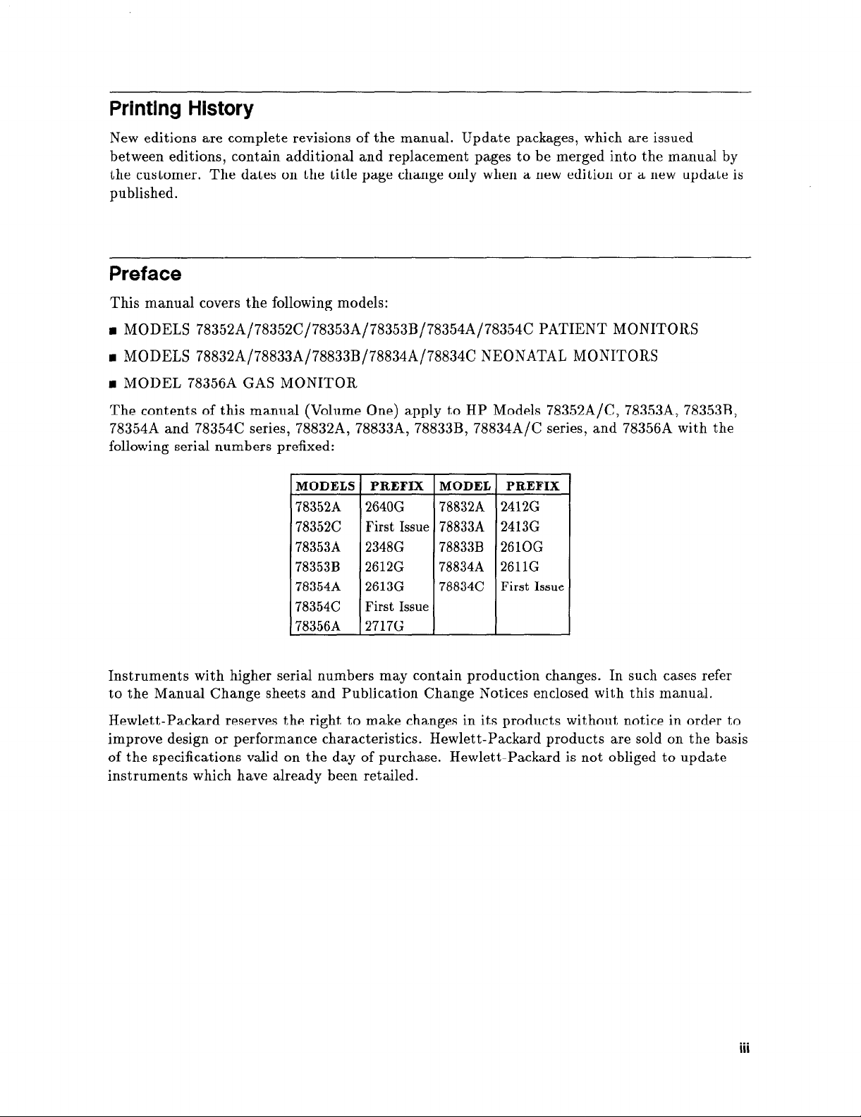
The contents of this manual (Volume One) apply to HP Models 78352A/C, 78353A, 78353B,
78354A and 78354C series, 78832A, 78833A, 78833B, 78834AfC series, and 78356A with the
following serial numbers prefixed:
MODELS PREFIX
78352A 2640G
78352C
78353A
78353B 2612G
78354A 2613G
78354C
78356A 2717G
First
2348G
First Issue
Issue
MODEL
78832A
78833A
78833B
788348
78834C
PREFIX
2412G
24136
2610G
2611G
First Issue
Instruments with higher serial numbers may contain production changes. In such cases refer
to the Manual Change sheets and Publication Change Notices enclosed with this manual.
Hewlett-Packard reserves the right to make changes in its products without notice in order to
improve design or performance characteristics. Hewlett-Packard products are sold on the basis
of the specifications valid on the day of purchase. Hewlett-Packard is not obliged to update
instruments which have already been retailed.
Page 4
CONTENTS OVERVIEW
This manual contains service information for the Hewlett-Packard 78352/3/4, 78832/3/4 and
78356A monitors. The information is divided into two sections:
w Chapter 1 - Service
n
Chapter 2 - Schematics
n
Chapter 3 - Replaceable Parts
Further sections covering Theory of Operation and Maintenance Checks are contained in
Volume 1 of the manual (part number 78354-9000A).
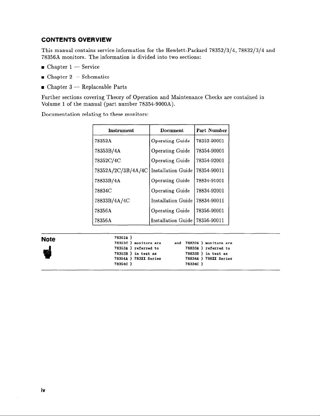
Documentation relating to these monitors:
Instrument Document Part Number
Note
78352A
Operating Guide 78352-90001
78353B/4A Operating Guide 78354-90001
78352C/4C
Operating Guide 78354-92001
78352A/2C/3B/4A/4C Installation Guide 78354-90011
78833B/4A Operating Guide 78834-91001
78834C
78833B/4A/4C
78356A
78356A
78352A
78352C ) monitors are and 78832A 1 monitors are
78353~ 1 referred to 78833A ) referred to
78353~ 1 in text as
783548 ) 783Xx
78354C ) 78334C )
>
Operating Guide 78834-92001
Installation Guide 78834-90011
Operating Guide 78356-90001
Installation Guide 78356-90011
Series
78833~ ) in text as
788348 ) 788Xx Series
iv
Page 5
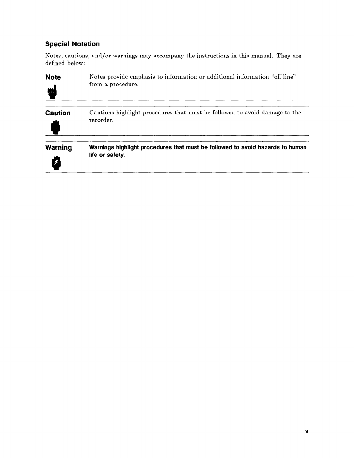
Special Notation
Notes, cautions, and/or warnings may accompany the instructions in this manual. They are
defined below:
Note
3
Caution
0
Warning
Notes provide emphasis to information or additional information “off line”
from a procedure.
Cautions highlight procedures that must be followed to avoid damage to the
recorder.
Warnings highlight procedures that must be followed to avoid hazards to human
life or safety.
V
Page 6

Page 7
Contents
1.
Service
Introduction
Disassembly and General Service Precautions
Cleaning
Extender Boards
Display uP Board Exchange
.............................
..............................
..........................
.....................
..............
1-1
1-2
1-3
1-3
1-3
la. Disassembly Procedures
3/4 and Full Modules
Top cover removal
Board Removal (display uP, interpolation or parameter)
Power Supply Assembly Removal
Power Supply Disassembly
Audio Module Removal
Front Panel Removal
Front Panel Disassembly
NIBP Board and Pump Removal
Mother Board Removal
lb. Reassembly Procedures
3/4 and Full Modules
Mother Board Installation
Board Installation
Front Panel Reassembly
Front Panel Installation
Power Supply Reassembly
Power Supply Assembly Installation
NIBP Pump and Board Reassembly (78352A/C and 78354A/C)
Cover Installation
..........................
..........................
.........................
.........................
...................
......................
.......................
........................
.......................
...................
.......................
.........................
......................
.......................
.......................
......................
..................
.........
.....
1a-1
1a-1
1a-1
1a-2
1a-3
1a-5
1a-6
1a-7
1a-9
1a-14
1b-1
1b-1
1b-2
1b-3
1b-5
1b-6
1b-9
1b-10
1b-10
1c. Adjustments
Introduction
CRT Adjustments
Interpolation Board Adjustments
Gain and Offset Adjustments
Baseline Width Adjustment
ECG Adjustments
Offset Adjustment
Notch Filter Adjustment
Power Supply Adjustments
System 780 Annotating Analog Interface (Opt. J11)
System 780 Configuration Adjustments
.............................
..........................
.........................
........................
......................
......................
...................
....................
....................
................
...........
1c-1
1c-2
1c-4
1c-4
1c-4
1c-7
1c-7
1c-7
1c-8
1c-9
1c-9
Contents-1
Page 8
Offset Adjustment ........................
SDN Configuration Adjustments
Instrument Identity ........................
Instrument Data Transmission Errors
Instrument Status Word
Binary to Hex Conversion Table
1d. Jumpers & Switch Programming
Jumpers & Switch Programming for all Boards
Mother Board: 78353-66501t and 78354-66501
Programming Switch S1
Conditions when switch closed
Programming Switch S2
Condition when switch closed
Programming Switch S3
Programming Switch S4
Summary of S1 and S2 switch positions for 78354-66501 Mother Board:
Display uP Board 78353/4-66502, 78354-66602 and 78354-66702
Programming Switch S1
Programming Switch S2
Programming Switch S3 (78354-66502 board only)
Interpolation Board 78353-66503
Programming Switch S1
Programming Switch S2 (
Jumpers
Audio Board 78353-6651 1/12
ECG Board (3-lead) 78832-66522
Programming Switch S 1
ECG Board (Full lead) 78354-66522, 66722
Pressure Board 78353-66532/4
Programming Switch S1
Programming Switch S2
How to change the pressure scaling mode:
NIBP Board 78354-66535 and 78352-66535
CO2/02 Board 78354-66540 and 78356-66540
Programming Switch S1 (78354-66540 only)
Programming Switch S1 (78356-66540 only)
Programming Switch S2
02 Board 78356-66541
Programming Switch S1 (78356-66541 only)
PAT Board 78354-66552
Programming Switch S1
Programming Switch S3
Temperature Board 78353-66554
Programming Switch S1
Temperature Board 78354-66554
Programming Switch S1
Programming Switch S3
Respiration Board 78832-66562
Programming Switch S1
tcp02/C02 Board 78834-66572
.............................
......................
......................
......................
......................
......................
......................
......................
......................
no on Revision C boards and higher) t
.....................
......................
....................
......................
......................
......................
........................
.......................
......................
......................
......................
......................
......................
....................
......................
....................
...................
................
..................
..................
...................
...................
...................
...............
...............
...................
...................
..............
.............
..............
.............
.............
.............
.............
..........
.....
.....
1c-9
1c-14
1c-15
1c-16
1c-16
1c-16
1d-1
1d-1
1d-1
1d-1
1d-2
1d-2
1d-3
1d-3
1d-4
1d-6
1d-6
1d-7
1d-7
1d-9
1d-9
1d-9
1d-10
1d-11
1d-12
1d-12
1d-13
1d-15
1d-15
1d-15
1d-16
1d-17
1d-20
1d-20
1d-20
1d-21
1d-21
1d-21
1d-23
1d-23
1d-23
1d-25
1d-25
1d-26
1d-26
1d-26
1d-27
1d-27
1d-28
Contents-2
Page 9
SpO2 Board 78354-66510 ......................
System Board 78353-66590 ......................
System Board 78353-66592 ......................
RS-232C Interface Board 78354-66598 .................
NIBP Board (78352-66538) ......................
Error Codes and Messages
le.
Introduction .............................
Error Codes .............................
ECG (783XX series) Error Codes: ...................
ECG (788XX series) Error Codes: ...................
Pressure Error Codes: .........................
NIBP Error Codes: .........................
CO2 Error Codes: ..........................
02 Error Codes: ..........................
Temperature (783XX series) Error Codes: ...............
Temperature (788XX series) Error Codes: ...............
Respiration Error Codes: .......................
tcpCO2/O2 Error Codes: ......................
SpO2 Error Codes: .........................
SDN Error Codes: .........................
780 Annotating Interface Error Codes: .................
Error Messages ............................
Defective Components On Display uP And Interpolation Boards ......
1d-29
1d-29
1d-31
1d-32
1d-33
1e-1
1e-1
1e-3
1e-3
1e-3
1e-3
1e-4
1e-4
1e-4
1e-4
1e-5
1e-5
1e-6
1e-6
1e-7
1e-8
1e-8
2.
Schematics
Introduction ............................. 2-1
Schematic Diagrams
2a.
Introduction .............................
Organization of Material in Chapter 2a ................
Board Compatibility Chart ......................
Exchange Board Overview ......................
2b.
Connection Boards
Introduction .............................
Replaceable Parts List
3.
Introduction .............................
How to Find a Part ..........................
ORDERING INFORMATION .....................
General Options for all types of Monitors ................
Right angle power cords are ordered under the following part number: ...
Instrument Model Number: 78352A ...................
Model Description: Surgical Monitor
.................
Parameter Option: #A01 (ECG) ...................
Parameter Option: #A11 (ECG, NIBP) ................
Parameter Option: #A13 (ECG, NIBP, 2TEMP) ............
Parameter Option: #A15(SPO2, NIBP)
Parameter Option: #A16 (ECG, SP02, NIBP) .............
2a-1
2a-1
2a-4
2a-6
2b-1
3-1
3-1
3-2
3-7
3-8
3-9
3-9
3-10
3-11
3-13
3-15
3-16
3-17
Contents-3
Page 10
Interface Option: #J10 (Limited 780 Interface)
Interface Option: #J11 (Annot. Interface)
Interface Option: #J12 (SDN Interface)
Interface Option: #J13 (RS232 Interface)
Instrument Model Number: 78352C
...................
Model Description: Surgical Monitor
Parameter Option: #A01 (ECG)
...................
Parameter Option: #A05 (ECG SP02)
Parameter Option: #A11 (ECG/NIBP)
...............
................
...............
.................
................
................
Parameter Option: #A13 (ECG/NIBP/2TEMP)
Parameter Option: #A16 (ECG/SPO2/NIBP)
Interface Option #J10 (Limited 780 Interface)
Interface Option #J11 (Annotating Interface)
Interface Option #J12 (SDN Interface)
Interface Option #J13 (RS232 Interface)
Instrument Model Number: 78354A
...................
Model Description: Surgical Monitor
Parameter Option: #A01 (ECG)
...................
Parameter Option: #A02 (ECG, PAT)
Parameter Option: #A03 (ECG,P1)
Parameter Option: #A04 (ECG, P1, PAT)
................
................
.................
................
.................
...............
Parameter Option: #A06 (ECG, P1, P2, T1, T2)
Parameter Option: #A08 (ECG, RESP, 2T)
Parameter Option: #A09 (ECG, RESP, 1 PRESS)
Parameter Option: #A10 (ECG, RESP, P1, P2)
Parameter Option: #A11 (ECG, RESP, PAT)
Parameter Option: #A12 (ECG, P1, P2, PAT)
Parameter Option: #A14 (ECG, SPO2, 2TEMP)
Parameter Option: #A17 (ECG, SPO2, 1PRESS)
Parameter Option: #A18 (ECG, SPO2, AUX, 1T)
Parameter Option: #A21 (ECG, RESP, 2T, 2P)
Parameter Option: #A22 (ECG, P1/2/3, PAT)
Parameter Option: #A23 (ECG, T1/2, P1/2/3)
Parameter Option: #A24 (ECG, RES, P1/2,PAT)
Module Option: #C01 (NIBP)
4/4 Module Option: #CO2 (CO2/O2)
4/4 Module Option: #C03 (C02/NIBP)
4/4 Module Option: #C06 (Dual PRESS)
....................
.................
................
...............
4/4 Module Option: #C16 (Dual PRESS, NIBP)
Parameter Option: #C18 (2PRESS, C02)
...............
Interface Option: #J10 (Limited Analog Interface)
Interface Option: #J11 (Annot. Interface)
Interface Option: #J12 (SDN Interface)
Interface Option: #J13 (RS232 Interface)
Instrument Model Number: 78354C
...................
...............
................
...............
Model Description: Patient Monitor (Adult)
Parameter Option: #A01 (ECG)
Parameter Option: #A03 (ECG, P1)
...................
.................
Parameter Option: #A06 ECG,P1,P2,T1,T2
Parameter Option: #A08 ECG RESP 2T
...............
Parameter Option: #A12 ECG P1,P2,PAT
.............
............
.............
.............
.............
............
..............
...........
............
.............
.............
............
...........
...........
............
.............
............
...........
............
...........
..............
..............
..............
3-19
3-19
3-19
3-20
3-21
3-21
3-22
3-23
3-24
3-26
3-28
3-30
3-30
3-31
3-31
3-32
3-32
3-34
3-35
3-36
3-37
3-38
3-39
3-40
3-41
3-42
3-43
3-44
3-45
3-46
3-47
3-49
3-51
3-53
3-55
3-57
3-59
3-61
3-62
3-64
3-66
3-66
3-66
3-67
3-68
3-68
3-69
3-70
3-71
3-72
3-73
Contents-4
Page 11
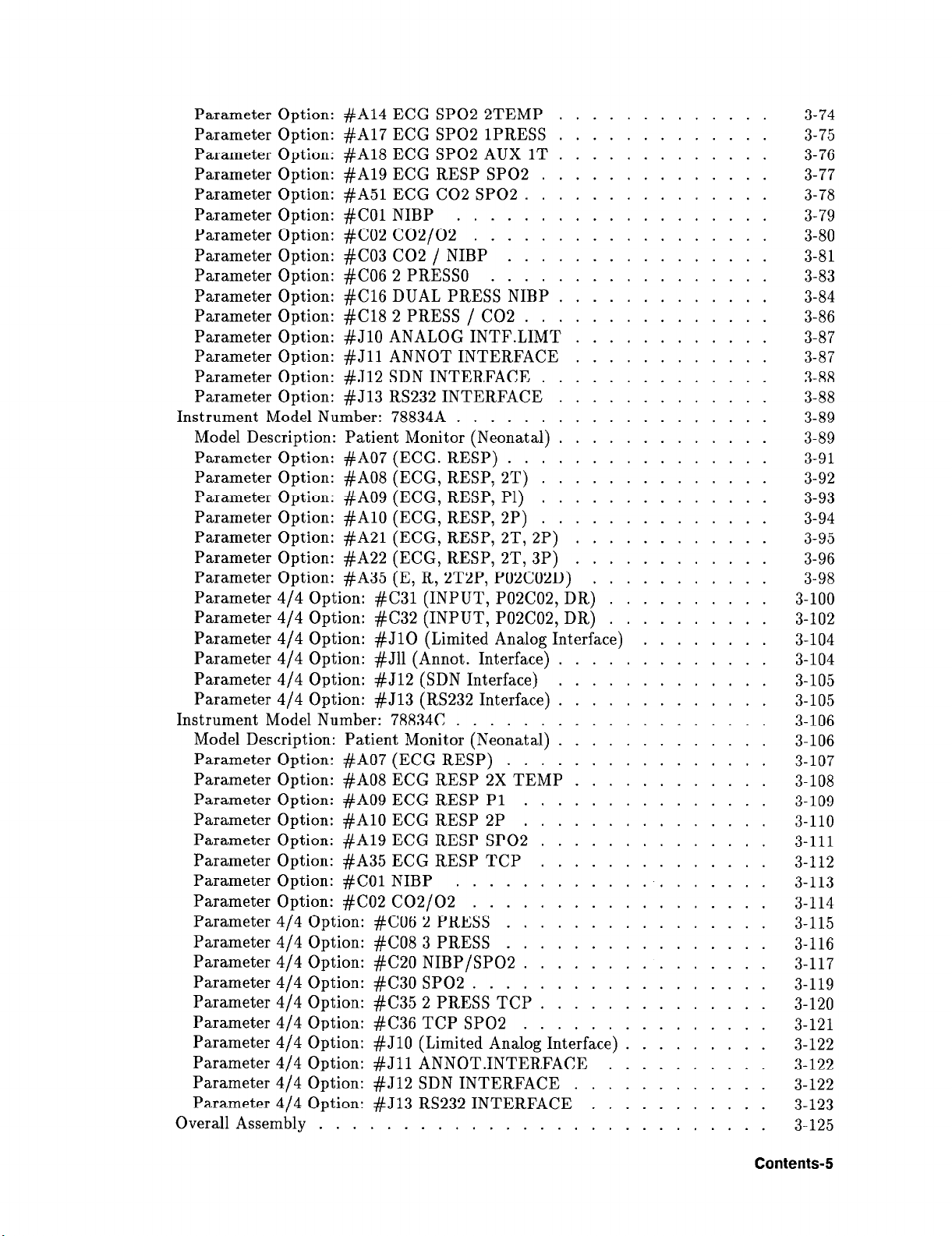
Parameter Option: #A14 ECG SPO2 2TEMP
Parameter Option: #A17 ECG SPO2 1PRESS
Parameter Option: #A18 ECG SPO2 AUX 1T
.............
.............
.............
Parameter Option: #A19 ECG RESP SPO2 ..............
Parameter Option: #A51 ECG CO2 SP02
Parameter Option: #C01 NIBP
Parameter Option: #C02 CO2/O2
...................
..................
Parameter Option: #C03 CO2 / NIBP
Parameter Option: #C06 2 PRESS0
Parameter Option: #C16 DUAL PRESS NIBP
Parameter Option: #C18 2 PRESS / CO2
Parameter Option: #J10 ANALOG INTF.LIMT
Parameter Option: #J11 ANNOT INTERFACE
Parameter Option: #J12 SDN INTERFACE
Parameter Option: # J13 RS232 INTERFACE
...............
................
.................
.............
...............
............
............
..............
.............
Instrument Model Number: 78834A ...................
Model Description: Patient Monitor (Neonatal)
Parameter Option: #A07 (ECG. RESP)
................
Parameter Option: #A08 (ECG, RESP, 2T)
Parameter Option: #A09 (ECG, RESP, P1)
Parameter Option: #A10 (ECG, RESP, 2P)
Parameter Option: #A21 (ECG, RESP, 2T, 2P)
Parameter Option: #A22 (ECG, RESP, 2T, 3P)
.............
..............
..............
..............
............
............
Parameter Option: #A35 (E, R, 2T2P, P02C02D)
Parameter 4/4 Option: #C31 (INPUT, P02C02, DR)
Parameter 4/4 Option: #C32 (INPUT, P02C02, DR)
Parameter 4/4 Option: #J10 (Limited Analog Interface)
Parameter 4/4 Option: #J11 (Annot. Interface)
Parameter 4/4 Option: #J12 (SDN Interface)
Parameter 4/4 Option: #J13 (RS232 Interface)
Instrument Model Number: 78834C
...................
Model Description: Patient Monitor (Neonatal)
Parameter Option: #A07 (ECG RESP)
................
Parameter Option: #A08 ECG RESP 2X TEMP
Parameter Option: #A09 ECG RESP P1
Parameter Option: #A10 ECG RESP 2P
Parameter Option: #A19 ECG RESP SPO2
Parameter Option: #A35 ECG RESP TCP
Parameter Option: #C01 NIBP
Parameter Option: #C02 CO2/O2
Parameter 4/4 Option: #C06 2 PRESS
Parameter 4/4 Option: #C08 3 PRESS
...................
..................
................
................
Parameter 4/4 Option: #C20 NIBP/SPO2
Parameter 4/4 Option: #C30 SPO2
..................
Parameter 4/4 Option: #C35 2 PRESS TCP
Parameter 4/4 Option: #C36 TCP SPO2
.............
.............
.............
.............
............
...............
...............
..............
..............
...............
..............
...............
Parameter 4/4 Option: #J10 (Limited Analog Interface)
Parameter 4/4 Option: #J11 ANNOT.INTERFACE
Parameter 4/4 Option: #J12 SDN INTERFACE
............
Parameter 4/4 Option: #J13 RS232 INTERFACE
Overall Assembly
...........................
...........
..........
..........
.........
..........
...........
........
3-74
3-75
3-76
3-77
3-78
3-79
3-80
3-81
3-83
3-84
3-86
3-87
3-87
3-88
3-88
3-89
3-89
3-91
3-92
3-93
3-94
3-95
3-96
3-98
3-100
3-102
3-104
3-104
3-105
3-105
3-106
3-106
3-107
3-108
3- 109
3-110
3-111
3-112
3-113
3-114
3-115
3-116
3-117
3-119
3-120
3-121
3-122
3-122
3-122
3-123
3-125
Contents-5
Page 12

Rear Panel Mechanical Parts/Chassis
General Internal Parts For Non-Invasive Pressure
A. Ordering Information
Direct Mail Order Program
Main Sales and Support Offices
United States of America
Other International Areas
......................
.....................
......................
......................
..................
3-127
............. 3-129
A-1
A-3
A-3
A-4
Contents-6
Page 13
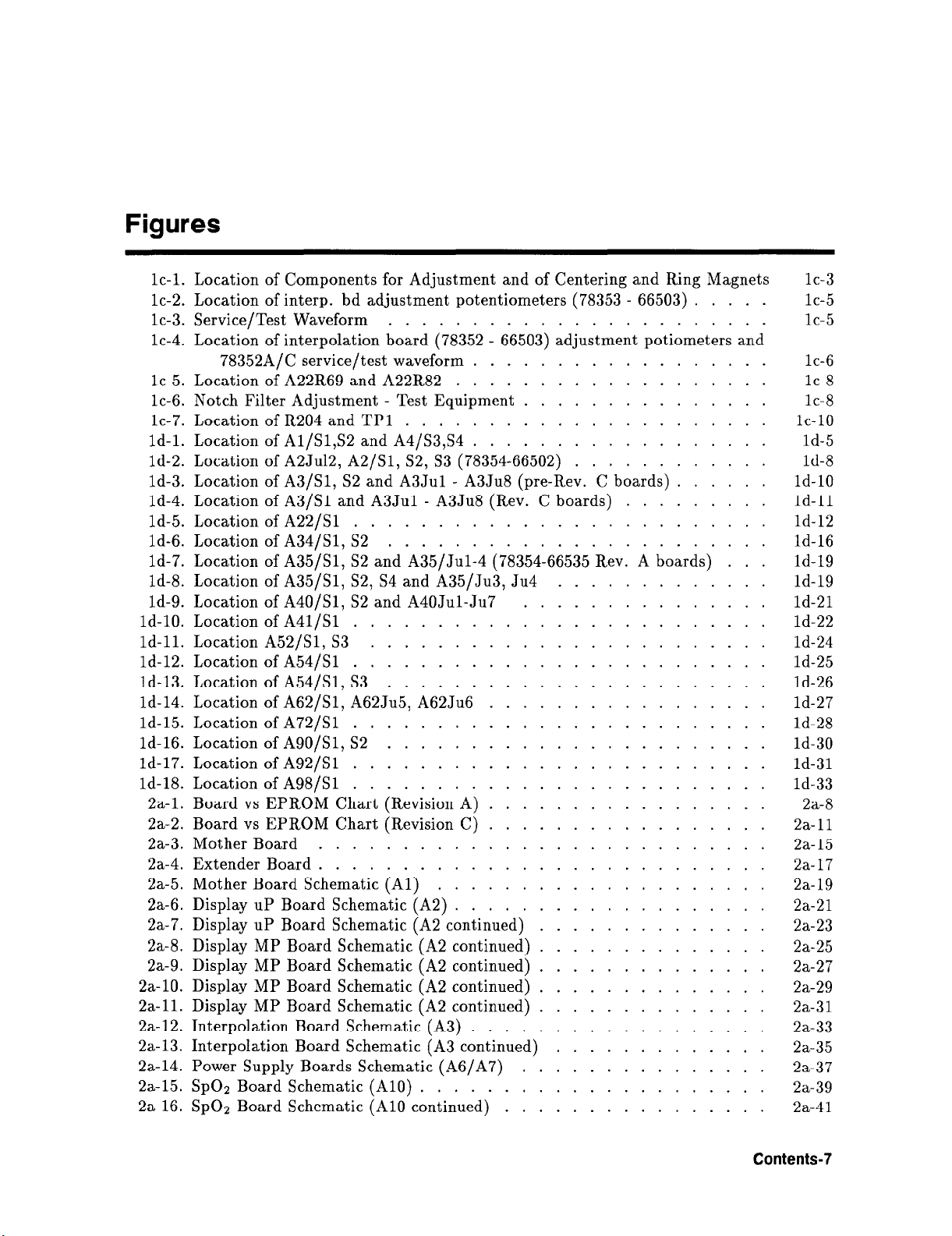
Figures
1c-1. Location of Components for Adjustment and of Centering and Ring Magnets
1c-2. Location of interp. bd adjustment potentiometers (78353 - 66503) .....
1c-3. Service/Test Waveform .......................
1c-4. Location of interpolation board (78352 - 66503) adjustment potiometers and
78352A/C service/test waveform ..................
1c-5. Location of A22R69 and A22R82 ...................
1c-6. Notch Filter Adjustment - Test Equipment ...............
1c-7. Location of R204 and TP1 ......................
1d-1. Location of A1/S1,S2 and A4/S3,S4 ..................
1d-2. Location of A2Ju12, A2/S1, S2, S3 (78354-66502) ............
1d-3. Location of A3/S1, S2 and A3Ju1 - A3Ju8 (pre-Rev. C boards) ......
1d-4. Location of A3/S1 and A3Jul - A3Ju8 (Rev. C boards) .........
ld-5. Location of A22/S1 .........................
1d-6. Location of A34/S1, S2 .......................
1d-7. Location of A35/S1, S2 and A35/Ju1-4 (78354-66535 Rev. A boards) ...
1d-8. Location of A35/S1, S2, S4 and A35/Ju3, Ju4 .............
1d-9. Location of A40/S1, S2 and A40Ju1-Ju7 ...............
1d-10. Location of A41/S1 .........................
1d-11. Location A52/S1, S3 ........................
1d-12. Location of A54/S1 .........................
1d-13. Location of A54/S1, S3 .......................
1d-14. Location of A62/S1, A62Ju5, A62Ju6 .................
1d-15. Location of A72/S1 .........................
1d-16. Location of A90/S1, S2 .......................
1d-17. Location of A92/S1 .........................
1d-18. Location of A98/S1 .........................
2a-1. Board vs EPROM Chart (Revision A) .................
2a-2. Board vs EPROM Chart (Revision C) .................
2a-3. Mother Board ...........................
2a-4. Extender Board ...........................
2a-5. Mother Board Schematic (A1) ....................
2a-6. Display UP Board Schematic (A2) ...................
2a-7. Display UP Board Schematic (A2 continued) ..............
2a-8. Display MP Board Schematic (A2 continued) ..............
2a-9. Display MP Board Schematic (A2 continued) ..............
2a-10. Display MP Board Schematic (A2 continued) ..............
2a-11. Display MP Board Schematic (A2 continued)
2a-12. Interpolation Board Schematic (A3) ..................
2a-13. Interpolation Board Schematic (A3 continued)
2a-14. Power Supply Boards Schematic (A6/A7)
2a-15. SpO2 Board Schematic (A10) .....................
2a-16. SpO2 Board Schematic (A10 continued) ................
..............
.............
...............
1c-3
1c-5
1c-5
1c-6
1c-8
1c-8
1c-10
1d-5
1d-8
1d-10
1d-11
1d-12
1d-16
1d-19
1d-19
1d-21
1d-22
1d-24
1d-25
1d-26
1d-27
1d-28
1d-30
1d-31
1d-33
2a-8
2a-11
2a-15
2a-17
2a-19
2a-21
2a-23
2a-25
2a-27
2a-29
2a-31
2a-33
2a-35
2a-37
2a-39
2a-41
Contents-7
Page 14
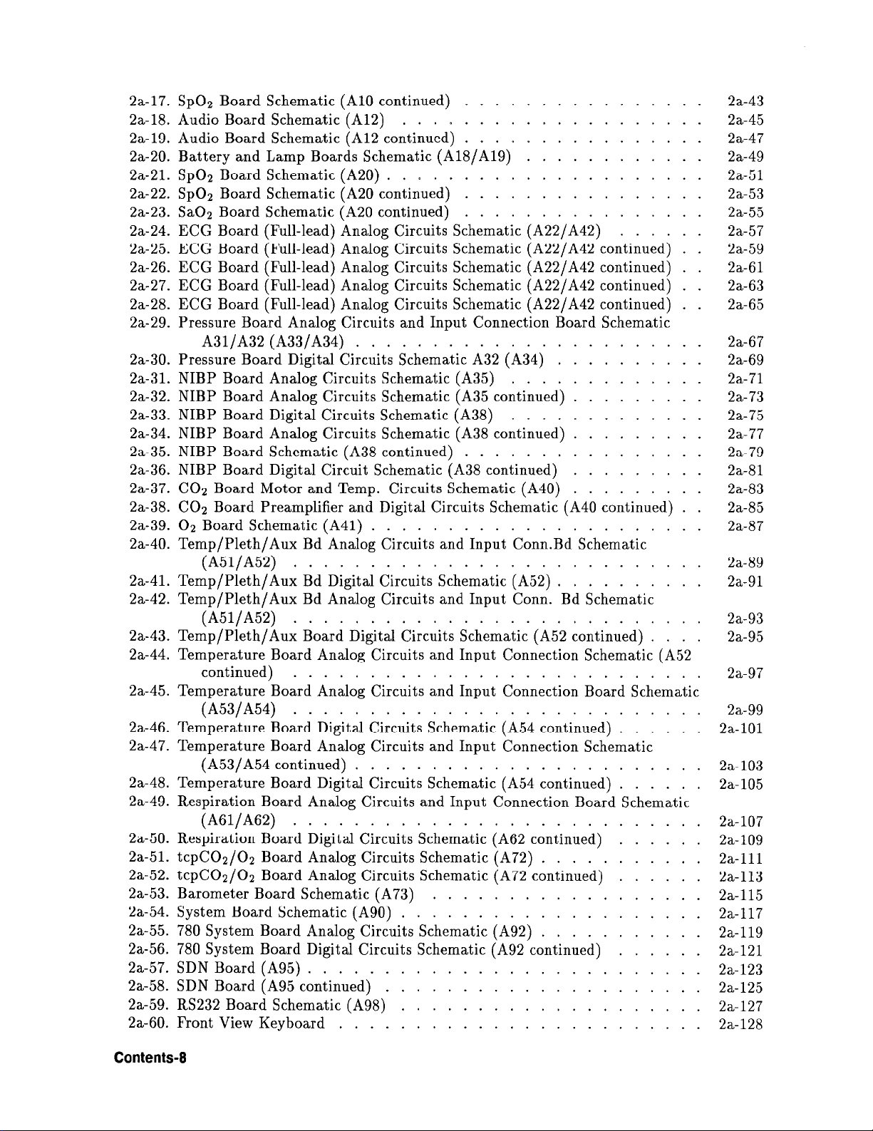
2a-17. SpO2 Board Schematic (A10 continued)
2a-18. Audio Board Schematic (A12)
2a-19. Audio Board Schematic (A12 continued)
2a-20. Battery and Lamp Boards Schematic (A18/A19)
2a-21. SpO2 Board Schematic (A20)
2a-22. SpO2 Board Schematic (A20 continued)
2a-23. SaO2 Board Schematic (A20 continued)
2a-24. ECG Board (Full-lead) Analog Circuits Schematic (A22/A42)
2a-25. ECG Board (Full-lead) Analog Circuits Schematic (A22/A42 continued) . .
2a-26. ECG Board (Full-lead) Analog Circuits Schematic (A22/A42 continued) . .
2a-27. ECG Board (Full-lead) Analog Circuits Schematic (A22/A42 continued) . .
2a-28. ECG Board (Full-lead) Analog Circuits Schematic (A22/A42 continued) . .
2a-29. Pressure Board Analog Circuits and Input Connection Board Schematic
A31/A32 (A33/A34) .......................
2a-30. Pressure Board Digital Circuits Schematic A32 (A34)
2a-31. NIBP Board Analog Circuits Schematic (A35)
2a-32. NIBP Board Analog Circuits Schematic (A35 continued)
2a-33. NIBP Board Digital Circuits Schematic (A38)
2a-34. NIBP Board Analog Circuits Schematic (A38 continued)
2a-35. NIBP Board Schematic (A38 continued)
2a-36. NIBP Board Digital Circuit Schematic (A38 continued)
2a-37. CO2 Board Motor and Temp. Circuits Schematic (A40)
2a-38. CO2 Board Preamplifier and Digital Circuits Schematic (A40 continued) . .
2a-39. O2 Board Schematic (A41)
2a-40. Temp/Pleth/Aux Bd Analog Circuits and Input Conn.Bd Schematic
(A51/A52) ...........................
2a-41. Temp/Pleth/Aux Bd Digital Circuits Schematic (A52)
2a-42. Temp/Pleth/Aux Bd Analog Circuits and Input Conn. Bd Schematic
(A51/A52) ...........................
2a-43. Temp/Pleth/A ux Board Digital Circuits Schematic (A52 continued)
2a-44. Temperature Board Analog Circuits and Input Connection Schematic (A52
continued) ...........................
2a-45. Temperature Board Analog Circuits and Input Connection Board Schematic
(A53/A54) ...........................
2a-46. Temperature Board Digital Circuits Schematic (A54 continued)
2a-47. Temperature Board Analog Circuits and Input Connection Schematic
(A53/A54 continued) .......................
2a-48. Temperature Board Digital Circuits Schematic (A54 continued)
2a-49. Respiration Board Analog Circuits and Input Connection Board Schematic
(A61/A62) ...........................
2a-50. Respiration Board Digital Circuits Schematic (A62 continued)
2a-51. tcpCO2/O2 Board Analog Circuits Schematic (A72)
2a-52. tcpCO2/O2 Board Analog Circuits Schematic (A72 continued)
2a-53. Barometer Board Schematic (A73)
2a-54. System Board Schematic (A90)
2a-55. 780 System Board Analog Circuits Schematic (A92)
2a-56. 780 System Board Digital Circuits Schematic (A92 continued)
2a-57. SDN Board (A95)
2a-58. SDN Board (A95 continued)
2a-59. RS232 Board Schematic (A98)
2a-60. Front View Keyboard
..........................
........................
....................
.....................
......................
....................
.....................
....................
................
................
............
................
................
......
..........
.............
.........
.............
.........
................
.........
.........
..........
....
......
......
......
...........
......
..................
...........
......
2a-43
2a-45
2a-47
2a-49
2a-51
2a-53
2a-55
2a-57
2a-59
2a-61
2a-63
2a-65
2a-67
2a-69
2a-71
2a-73
2a-75
2a-77
2a-79
2a-81
2a-83
2a-85
2a-87
2a-89
2a-91
2a-93
2a-95
2a-97
2a-99
2a-101
2a-103
2a-105
2a-107
2a-109
2a-111
2a-113
2a-115
2a-117
2a-119
2a-121
2a-123
2a-125
2a-127
2a-128
Contents-6
Page 15

3-1. Overall Assembly for Revison A,B and C
3-2. Power Supply Assembly
.......................
3-3. Rear Panel Mechanical Parts/Chasis
............... 3-125
................. 3-127
3-4. General Internal Parts for Non-Invasive Pressure
3-126
............ 3-129
Contents-9
Page 16
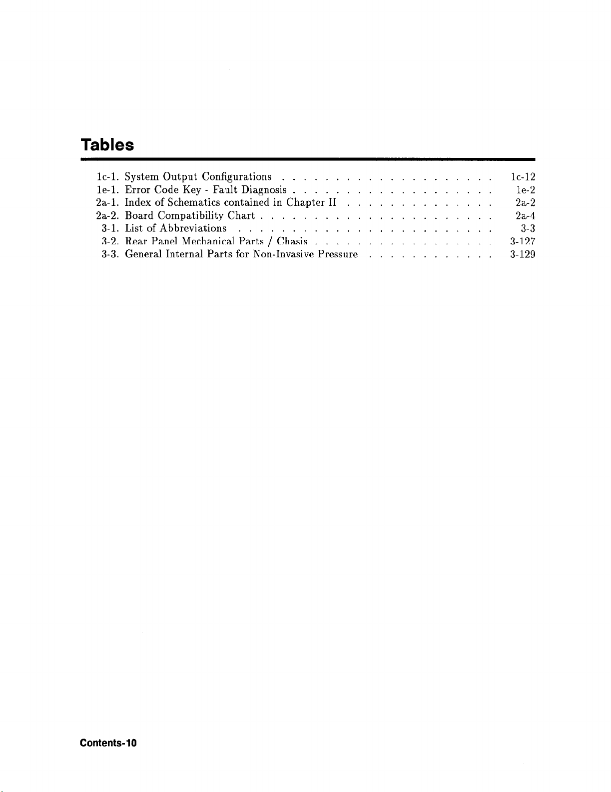
Tables
1c-1. System Output Configurations
1e-1. Error Code Key - Fault Diagnosis
2a-1. Index of Schematics contained in Chapter II
2a-2. Board Compatibility Chart
3-1. List of Abbreviations
3-2. Rear Panel Mechanical Parts / Chasis ................. 3-127
3-3. General Internal Parts for Non-Invasive Pressure
........................
.................... 1c-12
................... 1e-2
.............. 2a-2
......................
............
2a-4
3-129
3-3
Contents-10
Page 17
Service
Introduction
Chapters la, lb, lc, Id and le provide all the Service information required for the 78XxX
Series Patient and Neonatal Monitors. The Service Chapters cover the following:
n
Chapter la Disassembly Procedures
q
Top cover removal
o Board removal
(Display UP, Interpolation, Parameter)
q
Power supply assembly removal
q
Power supply disassembly
q
Audio module removal
q
Front panel removal
q
Front panel disassembly
q
NIBP Board and Pump removal
78354A/C monitor..78352A/C monitor
q
Mother Board removal
n
Chapter lb Reassembly Procedures
q
Mother Board installation
q
Board installation
o Front panel reassembly
q
Front panel installation
q
Power supply reassembly
o Power supply assembly installation
o NIBP reassembly
0 Cover installation
1
n
Chapter lc Adjustments
H Chapter Id Jumpers and Switch Programming
n
Chapter le Error Codes and Messages
Service l-1
Page 18
Disassembly and General Service Precautions
Caution
Read the following precautions thoroughly before performing any of the
disassembly procedures. Serious damage to the instrument can result if the
precautions are not strictly followed.
Y
n
The front panel is vulnerable to scratching. Avoid rough handling of the panel.
n
When the chassis is removed from the case, bare metal edges are exposed which can scratch
the work surface. Be careful that the sharp edges and corners of the chassis do not scratch
the work area surface.
n
The input amplifiers have a floating ground section which is isolated from the remainder of
the board.
Never handle this section of the board - oil, dirt, dust, etc., deposited on this section can
cause leakage paths which can degrade floating circuit isolation and performance.
n
Handle all circuit boards by the edges; CMOS circuits operate with currents in the
nanoampere range and leakage paths caused by skin oils, dirt, dust, etc., can cause
inaccurate circuit performance.
w As all of the screws in the Monitor have been treated with a special varnish they should not
be screwed in and out more than about ten times. After this, replace with new screws.
n
Generally, the insulation resistance of the oxide layer in MOS IC structures is very high, and
the oxide layer is very thin. Because of this, it is possible that the static voltages usually
present on clothes and the human body will be enough to generate a potential difference
across the insulator, high enough to cause a breakdown of the insulating layer.
The following precautions should be taken while handling these ICs. Particular care should be
taken under conditions of low humidity.
1. Store new ICs by inserting them into a urethanepolyester cushion (which is conductive), or
wrapping them in aluminium foil, so that all the pins are at the same potential.
(The ICs should be stored in that manner until mounted on the circuit board.)
2. Check the soldering iron for possible power-line leakage current. To do this, connect an
ohmmeter to the tip of the soldering iron and the plug. If there is a leakage path, use
another soldering iron.
3. Equalize any potential difference between the clothes, the tools in use, the work bench,
the set being worked on, and the packaged IC by touching them all in succession with the
hands or a conductive wire or tool.
4. When it is necessary to handle the IC with the fingers, do not touch any pin, hold the IC
at the ends of its plastic package case.
Warning
AVOID ELECTROSTATIC DISCHARGE !
l-2 Service
Page 19
The following precautions should be observed prior to beginning disassembly:
1. Turn the instrument off.
2. Remove the power cord and all signal cables from the rear panel.
Warning
In Chapter la the disassembly procedures are arranged from top assembly downwards.
Chapter lb contains information on reassembly.
If the instrument is to be reconnected and the power turned on with the rear
panel removed, low voltage and dangerous high voltage sources would be
exposed. Be careful. Do not power up the chassis on a conductive surface
such as a bare metal table. Place the chassis on a non-conductive material,
such as heavy cardboard.
Cleaning
The instrument should be clean and free of dust and dirt. Clean as required with a lint-free
cloth or sponge dampened with warm soapy water or alcohol. The front panel is more
sensitive to scratching than the other surfaces of the Monitor. Be careful, especially when
cleaning this surface.
Caution
dl
Do not allow any liquid to enter the instrument case. Do not pour liquid on
the instrument while cleaning. Never use any abrasive material such as steel
wool or silver polish, and never use strong solvents as acetone to clean the
monitor.
Extender Boards
Four extender boards and one cable are needed for servicing the Monitor:
lx 5061-5640
1 x 5061-5641 Interpolation Board / Display UP Board
1 x 5060-1805
1 x 78353-66589 Power Supply Extender Board (15 pin connector)
1 x 78353-61607 Power Supply Extender Cable
Parameter Board / Display UP Board
System Board
Display UP Board Exchange
After exchanging the Display UP Board, wait at least 20 seconds before switching the
instrument back on, otherwise an error message will be generated
Service l-3
Page 20

Page 21
Disassembly Procedures
314 and Full Modules
Top cover removal
1. Undo and remove the 4 upper screws on the instrument case.
2. Raise the front of the top cover and lift cover off.
Die beiden oberen Fotos von alter Seite l-5 nebeneinander hier einfiigen
la
Board Removal (display UP, interpolation or parameter)
1. Lift out the board stabilizer which holds the boards in place.
2. Undo the colored plastic clips at either end of the board.
Die beiden unteren Fotos von alte Seite l-5 nebeneinander hier einfiigen
Disassembly Procedures 1 a-l
Page 22
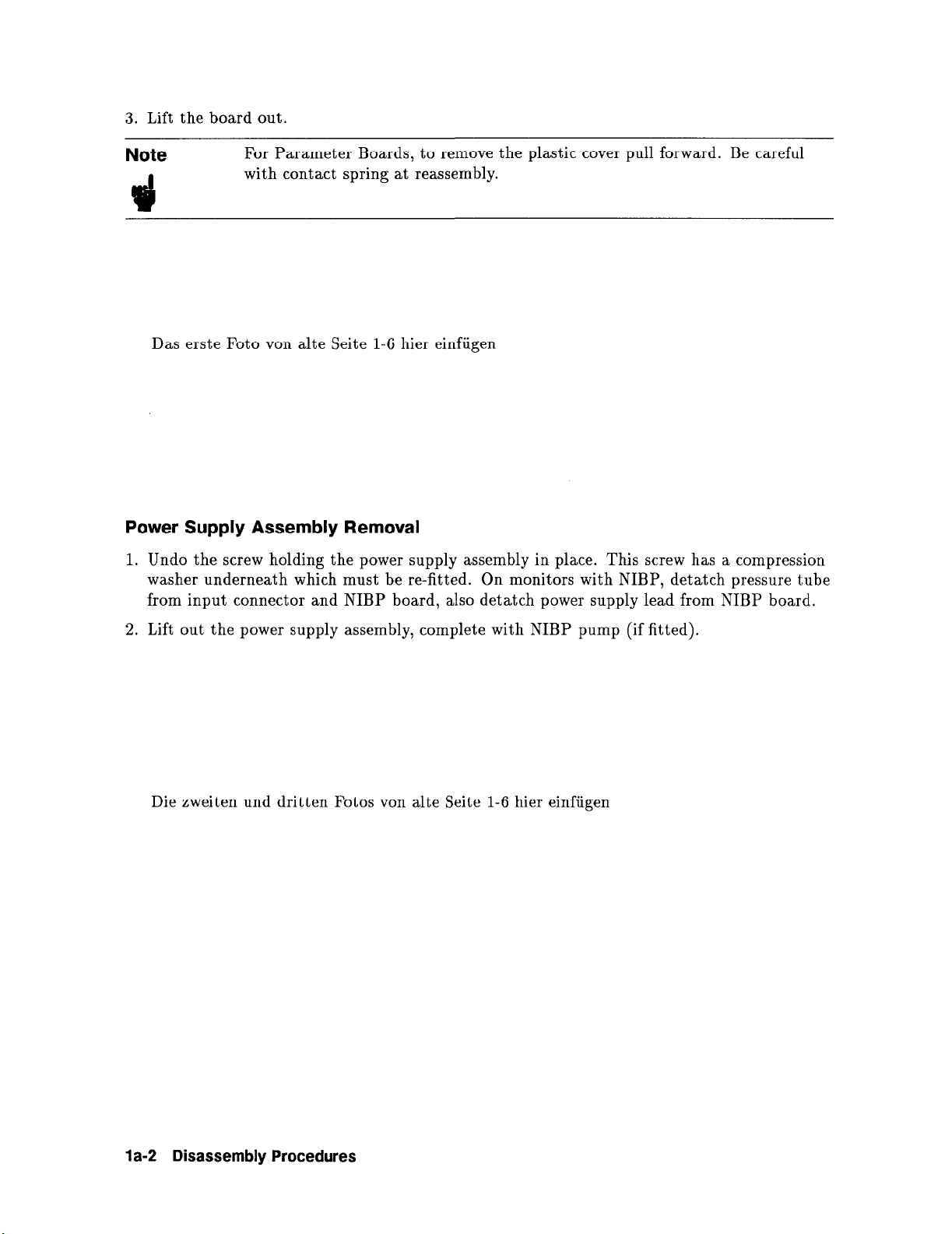
3. Lift the board out.
Note
3
Das erste Foto von alte Seite l-6 hier einfiigen
For Parameter Boards, to remove the plastic cover pull forward. Be careful
with contact spring at reassembly.
Power Supply Assembly Removal
1. Undo the screw holding the power supply assembly in place. This screw has a compression
washer underneath which must be re-fitted. On monitors with NIBP, detatch pressure tube
from input connector and NIBP board, also detatch power supply lead from NIBP board.
2. Lift out the power supply assembly, complete with NIBP pump (if fitted).
Die zweiten und dritten Fotos von alte Seite l-6 hier einfiigen
la-2 Disassembly Procedures
Page 23

Power Supply Disassembly
1. Remove the power supply cover by undoing the two screws on the top and the three screws
on the side.
Das let&e Foto von alte Seite l-6 hier einfiigen
2. For access to the secondary power supply board A6, unscrew the rear panel assembly
(2 screws).
3. Disconnect the transformer and battery connector (not shown).
Die beiden oberen Fotos von alter Seite l-7 nebeneinander hier einfiigen
4. Loosen the potential equalisation connector with a socket wrench and remove.
5. Slide out rear panel insert. (On later models the label is removed from underneath).
Die beiden unteren Fotos von alter Seite l-7 nebeneinander hier einfiigen
Disassembly Procedures 1 a-3
Page 24

6. Undo two screws holding the power inlet in position (required only for access to power
inlet).
7. For access to the primary power supply board A7, undo the three screws holding it into
position.
Die beiden oberen Fotos von alter Seite 1-8 nebeneinander hier einfiigen
8. Power supply board A7 is now fully accessible.
Das letzte Foto von alte Seite l-8 hier einfiigen
1 a-4 Disassembly Procedures
Page 25

1. Press the button on the top of the audio module cover, and pull the cover off the module.
Later models have a screw in the rear panel to secure the audio cover.
2. Undo the 1 or 2 screws on the inside of the audio module. Later models have only one
screw, remove this and slide the complete audio module out after disconnecting audio
module cable and battery board cable (optional).
Die beiden oberen Fotos von alter Seite l-9 nebeneinander hier einfiigen
3. Pull audio module a little away from the rear of the instrument and disconnect the cable
from the battery board. The battery board can now be removed (optional).
4. Disconnect the ribbon cable from X9 (and X19 if applicable) on the mother board and feed
out through the slot in the rear bracket. The audio module can now be removed.
Die beiden unteren Fotos von alter Seite l-9 nebeneinander hier einfiigen
Disassembly Procedures
1 a-5
Page 26

Front Panel Removal
1. The parameter boards must be lifted out before the front panel can be removed.
2. Disconnect the CRT socket, the ground wire, the cable to the keyboard assembly, the HV
connection and the choke connection.
Die beiden oberen Fotos von alter Seite l-10 nebeneinander hier einfiigen
3. Undo the screw on the inside of the front panel, next to the CRT, and tilt the front panel
assembly forwards.
4. 788Xx series, 78352C, 78354C
Disconnect the three lamp board wires from the mother board.
Die beiden unteren Fotos von alter Seite l-10 nebeneinander hier einfiigen
la-6 Disassembly Procedures
Page 27

5. 788Xx Series only
Undo the one screw on the lamp board and remove as shown (push the lamps from the
front of the panel to access the board).
78352C, 78354C and 78834C
The LED lamp board is mounted with two screws to the keyboard assembly and can only
be removed with the complete keyboard assembly.
6. Lift front panel assembly out.
Die beiden oberen Fotos von alter Seite l-11 nebeneinander hier einfiigen
Front Panel Disassembly
1. Unscrew the two CRT holders, one on either side of the tube.
2. Lift out the CRT, the CRT holders, grounding spring (earlier models have a side hook
which needs to be unclipped, it is not necessary on later models and cannot be re-ordered).
Die beiden unteren Fotos von alter Seite l-11 nebeneinander hier einfiigen
Disassembly Procedures la-7
Page 28

3. Unscrew the parameter connector assemblies (the type and fitting of the connector
assemblies varies depending on parameter configuration).
4. The cover can now be lifted off the assembly
(as
shown) and the connector can also be
removed from the front panel.
Note
Some connector boards have spring contact for shield connection. Be careful
at reassembly to avoid damaging the spring.
Die beiden oberen Fotos von alter Seite 1-12 nebeneinander hier einfiigen
5. Not applicable to the 78352C, 78354C and 78834C monitors:
Undo three screws to remove the keyboard assembly. (The keyboard assembly on the
78352C, 78354C and 78834C monitors is not removable, it is glued to the front panel).
Das letzte Foto von alte Seite 1-12 hier einfiigen
1 a-8 Disassembly Procedures
Page 29

NIBP Board and Pump Removal
78354A Monitors with old ac pump:
1. Pull out NIBP parameter board until access to the tube connections are possible.
Das erste Foto von alte Seite 1-13 hier einfiigen
2. Disconnect the tubes from the front panel and the T-piece leading to the pump. Leave
tube attached to board.
Das zweite Foto von alte Seite 1-13 hier einfiigen
Disassembly Procedures la-9
Page 30
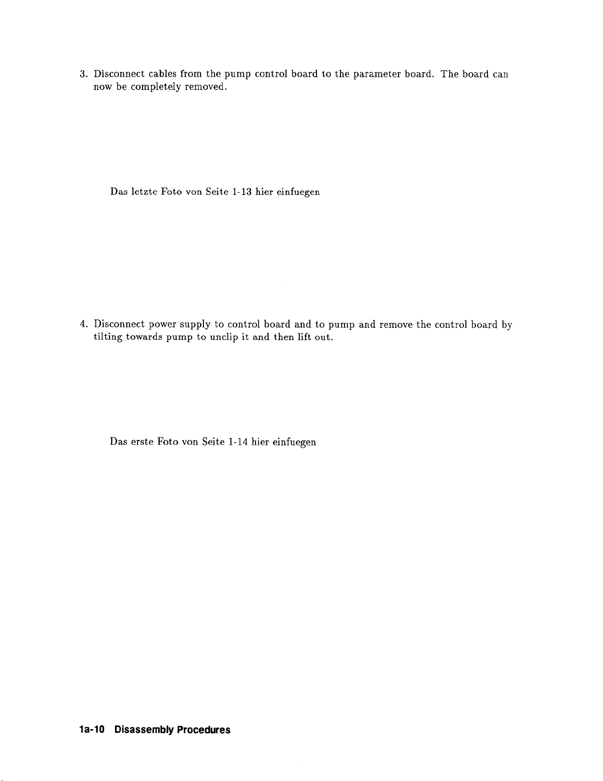
3. Disconnect cables from the pump control board to the parameter board. The board can
now be completely removed.
Das letzte Foto von Seite 1-13 hier einfuegen
4. Disconnect power supply to control board and to pump and remove the control board by
tilting towards pump to unclip it and then lift out.
Das erste Foto von Seite 1-14 hier einfuegen
la-10 Disassembly Procedures
Page 31

5. The four screws holding down the pump can now be removed (four outer X-headscrews).
Extender board with pump removed showing ribbon cable connections to the mother
board.
Das zweite Foto von Seite 1-14 hier einfuegen
6. The front panel can be removed by removing the screw shown and sliding out the panel.
Note the position of the switch assembly and LED board.
Das let&e Foto von Seite 1-14 hier einfuegen
Disassembly Procedures la-l 1
Page 32

78352A/C Monitor: 78354A/C with de pump:
1. Disconnect tubing from T-piece branch leading down to front panel connector and to
pump. Remove connector (brown and red wires) on NIPB board. This connects to the
pump control board.
Note
that
for the new NIBP Board (78352-66538),
orange wires) connects to the power supply and the pump.
th
e removed connector (black, brown, red,
Das erste Foto von alte Seite 1-15 hier einfuegen
2. The NIPB board and other parameter boards may now be removed.
Das zweite Foto von aIte Seite 1-15 hier einfuegen
la-12 Disassembly Procedures
Page 33

3. Pump:
to remove the pump remove connector (red and black wires) to pump control board
and remove the front 2 nuts securing the pump assembly to the vibration supports.(Refit
new external tooth lock washers if nuts are loosened p-n 2194-0413).
Note that for new NIBP Board, the pump is isolated when disconnected
supply and the board. The pump is removed by undoing two
the
power
4. Pump Control Board:
supply.
to remove the pump control board, disconnect from power supply,
nuts and
from
washers
the power
securing
remove screw (arrowed) and gently push down to free lower end of board from slot and
then rotate out. Note that the new NIBP Board has no pump control board.
Die beiden letzten Fotos von alter Seite 1-15 nebeneinander hier einfuegen
it to
Disassembly Procedures 1 a-l 3
Page 34

Mother Board Removal
1.
Note
2. Looking from front: Undo the screws holding the mother board in place: two on left (also
holding side LH bracket), three on right (one of which holds the Audio bracket), two on
rear (also holding rear bracket on some models) and one in center.
Die beiden oberen Fotos von alter Seite 1-16 nebeneinander hier einfuegen
3. Unscrew the green/yellow ground wire, which is also used to secure the Mother Board and
screening strip.
For access to the Mother Board, the front panel assembly does not necessarily
have to be removed. Simply tilt it forward - all cables are long enough to
permit this extension.
4. Undo the two screws which fasten the two grounding brackets to the Mother Board. Lift
grounding brackets out.
Die beiden unteren Fotos von alter Seite 1-16 nebeneinander hier einfuegen
la-14 Disassembly Procedures
Page 35

5. Lift up the Mother Board at the rear and pull out. (Picture shows side panels removed,
but this is not necessary).
6. The power on/off switch coupler rests in the bottom cover underneath the Mother Board.
Note position of nylon spacer ring.
Die beiden Fotos von alter Seite 1-17 nebeneinander hier einfuegen
Disassembly Procedures la-15
Page 36

Page 37

lb
Reassembly Procedures
3/4 and Full Modules
Mother Board Installation
1. Replace the Mother Board, making sure that the protrusion of the power on/off switch
coupler fits through the slot provided in the Mother Board.
2. Center the Mother Board with the center screw and replace LH side bracket and its 2
screws (early models also have a LH side center screw as shown). Replace the 3 screws on
the RH side (including Audio bracket and RH end of screening strip), the 2 rear screws and
screw holding green/yellow ground wire and LH end of screening strip. Do not tighten until
all 9 screws holding the Mother Board are back in position. (Some models may have upto
12 screws holding the board down).
Die beiden oberen Fotos von alter Seite 1-18 nebeneinander hier einfuegen
3. Reconnect the ground bracket (in later models this comes off with the Mother Board when
the two screws are released and a copper strip replaces the wire).
4. Reconnect the floating ground bracket (in later models this comes off with the Mother
Board when the two screws are released).
Die beiden unteren Fotos von alter Seite 1-18 nebeneinander hier einfuegen
Reassembly Procedures lb-l
Page 38
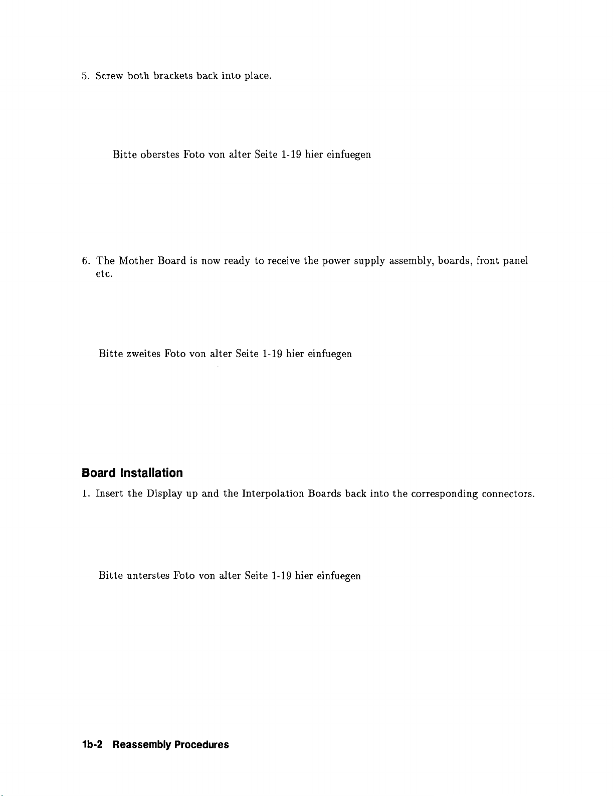
5. Screw both brackets back into place.
Bitte oberstes Foto von alter Seite 1-19 hier einfuegen
6. The Mother Board is now ready to receive the power supply assembly, boards, front panel
etc.
Bitte zweites Foto von alter Seite 1-19 hier einfuegen
Board Installation
1. Insert the Display up and the Interpolation Boards back into the corresponding connectors.
Bitte unterstes Foto von alter Seite 1-19 hier einfuegen
1 b-2 Reassembly Procedures
Page 39

Front Panel Reassembly
1. Make sure that the photo resistor on the keyboard assembly . . .
Bitte oberstes Foto von alter Seite l-20 hier einfuegen
2. . . . is positioned over the front-panel recess provided for this purpose.
Bitte zweites Foto von alter Seite l-20 hier einfuegen
3. Screw the parameter connector assemblies back into position (connectors facing upwards).
Bitte drittes Foto von alter Seite l-20 hier einfuegen
Reassembly Procedures 1 b-3
Page 40

4. Place
the CRT back into position - ensure no dirt or other material is trapped between
CRT and front panel screen.
5. Place screws in right-hand bracket. Do not tighten. Hook the grounding spring for the
CRT coating into position - do not bend the spring hook. Replace screws in left-hand
bracket remembering to include black wire from power lamp assembly.
Bitte letztes Foto von alter Seite l-20 hier einfuegen
6. Tighten all of the screws so that the CRT is positioned symmetrically. Hook up the other
end of the ground spring for the CRT coating.
Bitte erstes Foto von alter Seite 1-21 hier einfuegen
1 b-4 Reassembly Procedures
Page 41

Front Panel Installation
1. Fit the front panel assembly back into position.
Bitte zweites Foto von alter Seite 1-21 hier einfuegen
2. Reconnect the CRT socket, the ground wire, the cable to the keyboard assembly, the HV
connection and the choke connection. Reinsert parameter boards.
Bitte letztes Foto von alter Seite 1-21 hier einfuegen
Reassembly Procedures 1 b-5
Page 42

Power Supply Reassembly
1. Secure the power inlet connector back into position.
2. Insert primary power supply board A7.
Note: Make sure that Board fits exactly in slot of rear heat sink.
Bitte die beiden obersten Foto von alter Seite l-22 nebeneinander hier einfuegen
3. Screw back into place (two lower screws).
4. Reconnect transformer to the primary power supply board A7.
Bitte die beiden untersten Fotos von alter Seite l-22 nebeneinander hier einfuegen
1 b-6
Reassembly Procedures
Page 43

5. Position secondary power supply board A6 in slot provided and screw to rear panel.
6. Reconnect transformer to the secondary power supply board A6, making sure that all of
the connector pins make proper contact. Reconnect battery connection (if fitted).
Bitte die beiden obersten Fotos von alter Seite l-23 nebeneinander hier einfuegen
7. Reinstall power supply cover.
8. Screw two side screws back into position.
Bitte die beiden untersten Fotos von alter Seite l-23 nebeneinander hier einfuegen
Reassembly Procedures 1 b-7
Page 44

9. Screw rod back into position between the two power supply boards.
10. Secure top of cover with the two screws.
Bitte die beiden obersten Fotos von alter Seite l-24 nebeneinander hier einfuegen
11. Slot rear-panel insert back into position.
12. Secure rear panel insert by screwing the potential equalisation connector back into
position.
Bitte die beiden untersten Fotos von alter Seite l-24 nebeneinander hier einfuegen
1 b-8 Reassembly Procedures
Page 45

13. Check that the soldered ground connection is still intact.
Bitte oberstes Foto von alter Seite l-25 hier einfuegen
Power Supply Assembly Installation
1. Slot the power supply assembly into the bottom cover at the rear of the Monitor. Lower
the assembly back into position taking care not to clamp any of the cables underneath.
2. Screw power supply assembly back into position with the one screw required.
Bitte die beiden mittleren Fotos von alter Seite l-25 nebeneinander hier einfuegen
3. Check that power on/off switch coupler makes mechanical contact with the switch. Test
the on/off switch to see that it works.
Bitte unterstes Foto von alter Seite l-25 hier einfuegen
Reassembly Procedures 1 b-9
Page 46

NIBP Pump and Board Reassembly (78352A/C and 78354A/C)
Reassembly is the reverse of disassembly. With the 78352A monitor care should be taken
when sliding in the NIBP board not to trap the tubing leading to the transducer between the
NIBP board and any adjacent board. Fit tube leading down to front panel connector between
the board and RHS side panel. Note the correct tubing connections:-
78352A/C, 78354A/C
(dc pump)
78354A (ac pump)
Bitte die beiden obersten Fotos von alter Seite l-26 nebeneinander hier einfuegen
Cover Installation
Remount side covers (4 bottom screws) and put the board stabilizer back into position.
Remount top cover with 4 top screws.
Bitte die beiden unteren Fotos von alter Seite l-26 nebeneinander hier einfuegen
1 b-10 Reassembly Procedures
Page 47

lc
Adjustments
Introduction
In order to make any adjustments it is necessary to remove the top cover of the instrument;
so, during the adjustment procedures take care to avoid contact with exposed high voltage
sources.
To make any of the adjustments it is necessary to enter the monitor test mode.
To do this, first ensure that the monitor is switched off for at least 20 s.
Now press the softkeys labelled JL or (CalMark) and Z or (Suspend) simultaneously, then switch
the monitor on whilst keeping the buttons pressed. Hold pressed until the prompt tone is
heard. The CRT adjustment grid will now appear on the screen.
In this mode the softkeys have the following functions:
(cal,,,s;) n
Istopl STOP Press to display service/test waveform - non- overlapping
(used in “CRT Adjustments” and “Interpolation Board Adjustments”
See Figure lc-3*
(Overview) fi
(PatientData)~
(Record) q
The remainder of this section contains the detailed adjustment procedures.
*only one service/test waveform available in 78352A/C.
Press to display service /test waveform with channels 2
and 3 overlapping (used in “Interpolation Board Adjustments”.
Press to enter into system 780 configeration mode (only if
780 annotating system and SDN board is installed) (used in
“System 780 Configuration Adjustments”)
Press to display part numbers of ROMs loaded (hence
software revision status eg. 5180-XxXx, 5181-XxXx)
Adjustments 1 c-l
Page 48

CRT Adjustments
These adjustments are made using components on the motherboard and the CRT assembly
and are normally only required after a mother board or CRT exchange. The location of these
components is shown in Figure lc-1.
Display the CRT adjustment grid on the screen as described in “Introduction” then follow the
adjustment procedure below:
1. Optimize the display with cut-off adjust AlR55
2. If the horizontal synchronization is out of range, adjust with AlR21
3. Adjust the horizontal amplitude with AlR28. The vertical lines to the right and the left
of the grid should just be visible at the edge of the screen.
If the adjustment grid is not in a central position it will not be possible to make this
adjustment. In this case, rotate the centering magnets (see Figure lc-1) on the CRT until
the grid is centered then repeat the adjustment.
4. Adjust the linearity with AlR22. The horizontal grid subsections should all be of equal
length.
5. AlR28 and AlR22 are interactive, so repeat steps 3) and 4) until optimum result is
achieved.
6. Adjust the vertical amplitude with AlL2. The horizontal lines above and below the grid
should just be visible at the edge of the screen.
If the adjustment grid is not in a central position see paragraph 4) for centering
procedure.
7. Adjust the linearity with AlL3. The vertical grid subsections should all be of equal
length.
8. Next press the softkey labelled STOP to display the service/test waveform
(non-overlapping).
9. Check the interpolation - there should be no modulation of the test waveform intensity. If
there is modulation, adjust AlR55 again until it is reduced to a minimum.
10. Switch the instrument off then after 20 seconds back on again. The initial monitoring
display should appear.
11. Adjust the focus with AlR38.
lc-2 Adjustments
Page 49

12. Check the length of the baseline - it should be 97 mm.
13. Adjust the intensity with the rear panel screwdriver control.
14. Switch the monitor off and after 20 seconds on again, and display the CRT adjustment
grid. (see “Introduction”)
15. If the shape of the adjustment grid is distorted, i.e. the gridlines are curved, optimise the
shape by repositioning the small magnets on the ring at the front of the deflection yoke
assembly. See Figure lc-1.
Components for Adjustment Centering and Ring Magnets
Diagram und Photo von alte Seite l-29 hier einfiigen
Figure lc-1. Location of Components for Adjustment and of Centering and Ring Magnets
Adjustments lc-3
Page 50

Interpolation Board Adjustments
Note
The 78352A/C
monitor uses Interpolation Board 78352-66503, all other
monitors described in this manual use Interpolation Board 78353-66503.
78352A/C adjustments are contained in brackets.
Yll
All interpolation board adjustments are made using the nine potentiometers on the
78353-66503 board and three potentiometers on the 78352-66503 board.
Gain and Offset Adjustments
First enter the monitor test mode and press STOP key to display the service/test waveform in
non-overlapping mode (see “Introduction”). Now follow the adjustment procedure below:
a. Adjust the gain for channel 1 using A3RlO (78352A/C: A3/R19) until the distance between
the 1st (bottom) and 3rd levels of the step waveform is approximately the same as the
distance between the graticule lines.
b. Adjust the offset for channel 1 using A3R28 (78352A/C: A3/R29) until the two levels of
the step waveform are directly on the graticule lines
c. As A3RlO and A3R28 (78352A/C: A3/R19 and A3/R29) are interactive it may be
necessary to repeat steps a) and b) until an optimum result is obtained.
d. Adjust the gain and offset for.channels 2 and 3 as for channel 1 above but using A3R30,
A3R8 and A3R20, A3R18 respectively.
e. t To check the adjustment, press # or COverview) key to display the service test waveform
with channels 2 and 3 overlapping (see “Introduction”).
f. t The waveforms for channels 2 and 3 should be of equal size and the step waveforms level
with each other (Figure l-56). If not, adjust the offset and gain for channels 2 and 3 in this
mode until an optimum result is achieved.
Baseline Width Adjustment
Enter the monitor test mode and display the service/test waveform (see “Introduction”)
a. Adjust the width of the baseline of the channel 1 waveform using A3R37
A3/R12).
e waveform should have the same intensity at every point.
Th
(78352A/C:
b. t Adjust the baseline width of the channel 2 and 3 waveforms in the same way using
A3R39 and A3R38 respectively.
Note
t Not applicable to 78832A and 78352A/C)
lc-4 Adjustments
Page 51

OS1 Gl OS2
c2 OS3
G3
Wl W2
W3
r
Figure lc-2. Location of interp. bd adjustment potentiometers (78353 - 66503)
See Chapter lc for details on how to enter the following display modes:
Service/test waveform
(non-overlapping,
3 channel interp.)
Figure 103. Service/Test Waveform
Service/test waveform
(channels 2 + 3 overlapping,
3 channel Interp.)
Adjustments lc-5
Page 52

Figure 1 c-4.
Location of interpolation board (78352 - 66503) adjustment potiometers and 78352A/C
service/test waveform
1 c-6 Adjustments
Page 53

ECG Adjustments
Note
3
Offset Adjustment
1. Switch monitor on and connect ECG patient cable and lead set.
2. Short all the leads together.
3. Select diagnostic mode and ensure that switch 1 of A22Sl is closed.
4. Ensure that switch S2 on the mother board is programmed to output the ECG wave at the
rear panel phone jack (switch 4 closed and switches 1, 2 and 3 open).
5. Connect a DVM to the rear panel phone jack.
6. Adjust A22R69 so that the DVM reading equals OV f 20 mV.
Notch Filter Adjustment
60 Hz
50Hz
1. Connect the test equipment as shown in Figure lc-5
Note: all boards are already adjusted in the factory.
78832-66542, 78354-66542
78832-66522, 78354-66522
2. Ensure that switch S2 on the mother board is programmed to output the ECG wave at the
rear panel phone jack (switch 4 closed and switches 1, 2 and 3 open)
3. Switch monitor on and select diagnostic mode and lead II.
4. Apply a 5 V peak-to-peak sine wave at 50 or 60 Hz (main frequency) to the test circuit.
5. Trigger the oscilloscope to the line frequency (only possible when the line frequency equals
the notch frequency).
6. Adjust A22R82 until the wave ouput displayed on the oscilloscope is at minimum
amplitude.
Note
The Full Lead ECG board (78354-66522) has 3 switches, the positions and
location of which are shown in the Jumper & Switches in “ECG Board (Full
lead) 78354-66522, 66722” in Chapter Id.
Adjustments 1 c-7
Page 54

Figure lc-5. Location of A22R69 and A22R82
78SXX ser1er
14337A114336A
REAR-PANEL REAR-PANEL
PHONE JACK PHONE JACK
OSCILLOSCOPE OSCILLOSCOPE
P.N.
10501A
FUNCTION
GENERATOR
TEST
CIRCUIT
769XX serie*
149678114467A
PATIENT CABLE
,- ----1
#$
Figure 106. Notch Filter Adjustment - Test Equipment
Power Supply Adjustments
-4 Volt Adjustment
a. Switch the monitor on.
b. Connect a DVM to ground and to the -4 V test pin at the top of the power supply board
A6.
c. Adjust A6, R5, located next to this pin, so that the DVM reading equals -4 V f 3 mV.
1 c-8 Adjustments
Page 55

System 780 Annotating Analog Interface (Opt. Jll)
The annotating 780 system board (78353-66592) provides full parameter, alarm and recorder
information. There are six alternative output- connector configurations which are shown in
table 1. (For more detailed information please refer to pages l-42 to l-44)..
System 780 Configuration Adjustments
The system interface is configured using the softkeys. First, enter the system 780
configuration mode as described in “Introduction”.
The functions of the softkeys are now as follows:
Cal Mark JL
Press to select one of the seven possible configurations of
the signals at the system output connector (see Table lc-1).
(Stop) STOP
(Overview) #
Press to select latching or nonlatching system alarms.
Press to change temperature offset (see offset adjustment
below). This should not be necessary as the value is set at the
factory.
[PatientData)D
Press to change general parameter offset (see offset adjustment
below). This should not be necessary as the value is set at the
factory.
Record IL
Press to store configuration values. When store procedure is
successfully completed the monitor returns to the previous
operating level and the CRT adjustment grid is displayed.
Off set Adjustment
It may be necessary to adjust the system 780 board if the EAROM has lost information. In
this case follow the procedure below:
a. General parameter offset
With the monitor in system ‘780 configuration mode, measure the general offset at TPl. If
it is zero volts the offset is correct. If it is not zero volts the offset must be adjusted using
the softkey indicated above.
The softkey label will show the offset correction step number and will rotate over the full
positive and negative range, increasing the number by one each time the key is pressed.
Press the softkey until the value is zero volts. The step size is 2.5 mV.
b. Temperature parameter offset
Note
With option N12 (G erman temperature standards) this adjustment is not
possible.
With the monitor in system 780 configuration mode, measure the temperature offset on pin
10 of system output connector (J91). If it is zero volts the offset is correct. If it is not zero
volts the offset should be adjusted. To enable the adjustment procedure, connect X3 pin 2
to ground.
Adjustments 1 c-9
Page 56

For adjustment, use the temperature offset softkey. The procedure is the same as for the
general parameter offset described above. Press the softkey until the value is zero volts.
The step size is 1.25 mV.
c. Store the offset correction values by pressing the store softkey. The monitor returns to the
previous operating level (monitor test mode) when store procedure is complete.
Note
d. Temperature gain adjustment
Note
With the monitor in
signal on pin 10 of system output connector (J91). The measurement value in this
operating level should be 2.558V f 0 mV, otherwise adjust with potentiometer R204.
A gain adjustment is necessary in monitor test mode for temperature.
With option N12
possible.
monitor test
(G erman temperature Standards) this adjustment is not
mode (grid raster display) measure the temperature
lc-10 Adjustments
Figure 1~7. Location of R204 and TPl
Page 57

Explanation of Configurations in Table lc-I.
Configuration 0:
Configuration 1:
Configuration 2:
Configuration 3:
Configuration 4:
Configuration 5:
Configuration 6:
Monitor with 7811B control center without arrhythmia
system. Bedside recorder 78171/2/3.
Monitor with 78501/2/4/8 Speakeasy control center without
arrhythmia system.
Monitor with 7811B control center with arrhythmia system.
No parameter values Systole and Diastole for invasive blood
pressure 2.
Monitor with 78501/2/4/8 Speakeasy control center with
arrhythmia system. No Resp. or CO2 curve.
Corresponds to Config. 0, but with a fixed allocation of
the recorder channels 1 and 2 with “Delayed ECG” on channel
1 and “Delayed Press 1” on channel 2. This corresponds to
the default configuration in Config. 0.
Special neonatal version with CRG-option. Cannot be
selected on the adult-monitor mode. Switch Sl must be
opened in operation with 8232 alarm recorder.
Only on OR multi-channel recorder. This version cannot be
selected on the German language option as there is no
allowance by PTB on 2. temperature.
Warning
In configurations O-4 and 6, the switch Sl must be closed.
Adjustments 1~11
Page 58

Table lc-1. System Output Configurations
J92
pin
no.
1 ECG wave
2 pleth wave encoded pleth wave encoded pleth wave
3 signal gnd.
4 recorder encoded recorder encoded recorder tcpcoz
5
6
7 INOP
8 reset
9
10 temp 1.
11 resp. rate
12
0 1 1*
deselect deselect
data alarm data alarm
recorder
return INOP return INOP return
encoded recorder encoded recorder ‘Temp.2 ***
Configurations O-6
2 3 4
analog
alarm gnd.
heart rate average
patient alarm
5s 6
tcpo2
data
***
A
scaled
pressure 2 pressure 2 pressure 2 pressure 2 pressure 2
wave
B
C
absolute
(6’3)
scaled absolute scaled absolute
pressure 1 pressure 1 pressure 1 pressure 1
wave
scaled
wave
systolic
pressure 1
D diastolic
pressure 1
E
F
H
CO2 /resp. resp. CO2 wave resp scaled
wave wave wave pressure 2 wave
systolic absolute systolic cardio
pressure 2 pressure 1 pressure 2
mean heart rate
pressure 2
wave (300) mode
absolute scaled tcpco* ECG wave
(60)
(300)
wave
wave
wave
absolute
pressure 2
wave
absolute
pressure 3
wave
CO2 wave
b-to-b
**
pleth wave
respirogram
resp.
wave
1~12 Adjustments
Page 59

Table 1~1. System Output Configurations (continued)
592
pin
no. 0
J
K
L diastolic
M mean
N
*
**
***
****
output configuration for CO2 /02 parameter
for cardiorespirogram mode, switch Sl on system board should be open
no Aux Wave because it is available as analog signal
output configuration not available in German Language Option (PTB)
recorder ET COz recorder scaled delayed delayed NIBP wave
channel 2 channel 2 pressure 1 pressure 1
pressure 2 pressure 2 pressure 2
recorder control control recorder control delayed
channel 1 state 1 state 5 channel 1 state 1 ECG wave HR b-to-b
1
Fi 02
Configurations O-6
1* 2 3 4 5# 6
resp.
wave wave wave
ALARM ON/
OFF
absolute diastolic Fi 02
wave (60)
ET CO2
pressure 1
delayed HR b-to-b
***
#
only available in 788Xx series
Adjustments 1~13
Page 60

SDN Configuration Adjustments
The system distribution network board is configured using the softkeys.
To do this, first ensure that the monitor is switched off for at least 20s. Now press the keys
labelled JL or [Cal) and E or (Suspend) simultaneously, then switch the monitor on
whilst keeping the buttons pressed. Hold pressed until the prompt tone is heard. The CRT
adjustment grid now appears on the screen.
Enter the SDN configuration mode by pressing m or (Patient] key and the following
display will appear:
SYSTEM
NETWORK TEST (CalMark) J-L
FACTORY DATA (Stop) STOP
ECHO (Overview) #
(Patient-a
BACK TO SETUP (Record) H Press to return screen to grid display
When the NETWORK TEST softkey is pressed the following display appears:
NEXT BRANCH
(Cal)
Press to select branch connection information
Press to select sensitivity, R/Y or INOP alarms,
alarm mode and arrhythmia on/off.
Press to initiate test - comprises of a 500 TEST
word message transmitted to the SDN board
(performed in the factory only)
. . .
JL Press for next branch
(up to 321
BRANCH 0 (Stop) STOP
OOlC
28
f&xi-) #
BACK TO SETUP
Pressing the NEXT BRANCH softkey advances the display to the next branch in the network
upto the maximum number of 32 branches. The information in the center of the screen
indicates the branch being observed and the identity of the downstream instrument (in this
case a 78504A Patient Information Center - see following “Instrument Identity”). The second
entry (OOlC) encodes the instrument status (see following “Instrument Data Transmission
Errors” and “Instrument Status Word”).
(iGi-- 8.. Press
to return softkeys
to
SYSTEM display
1~14 Adjustments
Page 61

Pressing the FACTORY DATA softkey gives the following display;
FACTORY DATA SYSTEM
AL CONF =RYI [Mark) n
Select sensitivity RY, RI or RYI
alarm configuration
AL MODE =AUTO lstopl STOP
Select either AUTO or DEMAND for
alarm display t
AR WAVE=ON (Overvie;v) @
Select on or off arrhythmia
delayed ECG wave
(Patient-a
STORE CONF ljj) L-51
. . .
Press to store and return
display to previous
Pressing the ECHO TEST softkey clears the display of all other functions and only the
words ECHO TEST are left on the screen. This function is performed in the factory during
service checks and a 500 word message is transmitted to the SDN board for processing and
re-transmission back to the board testing device.
Note
t DEMAND mode is the standard setting on the 78352A/C monitor and on
other instruments with SDN the standard setting is AUTO.
3
Note
The alarm latching/non-latching function of the SDN board is selected on
switch block Sl, visual alarm switch 7, on the Display UP Board.
Instrument Identity
YY Instrument
03 785348
28 785048
48 785048
68 78504A
88 785048
A8 7850411
C8 785046
28 785088
48 785088
68 78508A
8A 785088
AA 78508A
CA 7850811
ID no.
Adjustments lc-15
Page 62

Instrument Data Transmission Errors
BIT
76543210
l....... False SPS Event Flag
1 . . . Fatal Control Error Flag
l.....
1 Physical Data Error Flag
l... Logical Data Error Flag
1..
1. System Cycle Failure Flag
. . . . . .
Recoverable Control Flag Error
Poll Cycle Overflow Flag
Bo Error
Instrument Status Word
BIT
76543210
x.. .
x.. .
0
1
. . .
. . .
x..
0 . .
1.
x
0 .
1..
Self Test State (=l during Self Test)
Configuration State
Autopoll
SDU
DLC Line State
Offline
Online
System Cycle State
Local
Betaork
xx
Start/Restart Indicators
2 .
starting = 1
2
Restarting = 1
Binary to Hex Conversion Table
Binary Her
0 0000
0 0001
0 0010
0 0011
0 0100
0 0101
0 0110
0 0111
0 1000
0 1001
0 1010
0 1011
0 1100
0 1101
0 1110
0 1111
1 0000
0
1
2
3
4
5
6
7
8
9
A
B
c
D
E
F
10
lc-16 Adjustments
Page 63

Id
Jumpers & Switch Programming
Jumpers & Switch Programming for all Boards
Mother Board: 78353-665013 and 7835446501
Switches Sl and S2 on the Mother board are accessible when the top cover and parameter
boards are removed.
Programming Switch Sl
The Switch functions are shown below:
Conditions when switch closed.
1 Aux alarm to XlOC/18 (78353-66552
PAT Board only)
2 +5V buffered from A19 to XlOC/18
(OPEN = No Trend)
3 RESET signal is routed to X19 pin
14
Switch Sl
4 RESET signal is routed to System -
connector X91 pin 13
5 No contact
6 ICU alarm volume, possible to turn
alarm volume down to zero
7 QRS tone for Japan (switch closed
for option 202)
8 Standard QRS tone (OPEN for
option ZO2)
76366A
Jumpers & Switch Programming Id-1
Page 64

Note
Either 2 or 1 must be open
The QRS tone is not available on the 78356A monitor. Switches Sl-7 and 8
should OPEN.
Note
t78354-66501 board replaces 78353-66501.
If replacement board is ordered check that the Revision number of the board
is B-2513, C or greater. If it is not then for monitor 78834A Opt A22 only,
connect pin 11 on X83 to pin 6 on X4 (see wiring diagram). This is already
done on boards 78354-66501 with Revision B-2513, C or greater.
Programming Switch S2
This switch controls which parameter wave is present at the phone jack output on the rear
panel.
Condition when switch closed.
1 Not connected
2 Parameter wave from XlOC
3 Parameter wave from XlOB
4 Parameter wave from XlOA
Note
Standard settings are listed in summary table opposite.
Switches 4 should be in the CLOSED position to get the
ECG wave on limited I/F output. If this is abered the
label on the side panel should be changed.
The parameter wave options are not available on the
73352A
78356A
78356A monitor. Switches S2-2 and 3 should be open.
Switch S2
ld-2 Jumpers & Switch Programming
Page 65

Programming Switch S3
Switch S3 is located on the Extender Board.
1 OPEN: No parameter wave from Mother Board
CLOSED: Parameter wave from Mother Board
2 Parameter wave from Y/X6C} Sl
3 Parameter wave from Y/XGB} must be
open
Switch S3
4 Parameter wave from Y/XGA} OPEN
Note
Standard setting is SI CLOSED, S2/S3/S4 OPEN.
Sl is OPEN if 2 or 3 or 4 switch are CLOSED.
Programming Switch S4
Switch S4 is located on the Extender Board and configured according to the instrument and
option:
78354A #A22, #A23
1 CLOSED } K4 to 1 OPEN } K5 to
2 OPEN } Keyboard 2 CLOSED } Keyboard
3 OPEN }
4 CLOSED } code-2 4 OPEN } code-3
Slot
78834A #A22
3 OPEN }
Slot
Switch S4
All other options:
1 OPEN } no K
2 OPEN } to Keyboard
not used } Slot is
not used } not used
Jumpers 81 Switch Programming id-3
Page 66

Summary of Sl and S2 switch positions for 78354-88501 Mother Board:.
Sl Function when
783528 783538 78832A 788338 78833B 78353B
783568
Switch closed
78352C
78354A/C
78834A/C
1 Aux alarm OPEN
2
+5V Buffered
CLOSED OPEN CLOSED CLOSED CLOSED CLOSED
CLOSED OPEN OPEN OPEN
OPEN
OPEN
CLOSED
Reset to X91-13(Ltd.I/F) CLOSED CLOSED CLOSED CLOSED CLOSED CLOSED
3
CLOSED
4 Reset to X19-4(alrm Imp) CLOSED CLOSED CLOSED CLOSED CLOSED CLOSED
CLOSED
5
No contact
6 ICU alarm vol. zero
7
Japan QRS tone( 202)
8
Std. QRS tone
OPEN
OPEN
CLOSED CLOSED CLOSED CLOSED CLOSED CLOSED OPEN
OPEN OPEN OPEN OPEN OPEN OPEN
OPEN
OPEN
OPEN OPEN
OPEN
OPEN
s2
1
No contact
2
Param. wave from XlOC
3
Param. wave from XlOB
4
Param. wave from XlOA
OPEN
CLOSED OPEN OPEN OPEN
CLOSED CLOSED CLOSED CLOSED CLOSED CLOSED OPEN
OPEN
OPEN
OPEN
OPEN OPEN OPEN
OPEN OPEN OPEN
ld-4 Jumpers 81 Switch Programming
Page 67

Blatt von alte Seite 1-42 hier einfiigen
Figure Id-l. Location of Al/Sl,SP and A4/S3,S4
Jumpers & Switch Programming id-5
Page 68

Display UP Board 78353/4-66502,78354-66602 and 78354-66702
Jumpers: Ju2 on the Display UP board is set at 0 ohm.
Programming Switch Sl
Switch Sl on the Display UP board is accessible when the top cover and the left side cover
have been removed. It consists of eight mini switches. The functions of these switches are
shown below.
I
L
Switch Sl
OPEN
1 Trend
2 Alarm reminder
every 3 minutes
3’ 2 channel display
4 78353-66592 or
78353-66595 loaded
5 Alarms off at power-on
6 Audible Alarm latched
7 Visual Alarm latched
8 Adult monitor
(78352/3/4)
*No effect on 78354-66702
CLOSED
No Trend
Silent Mode
3 channel display
78353-66590 or
no system board loaded
Alarms off for three minutes
the automatically switched on
Audible Alarm non-latched
Visual Alarm non-latched
Neonatal monitor (78832/3/4)
On models before 1st June 88, there are two more sets of switches. These are replaced by
jumpers on current models:
ld-8 Jumpers & Switch Programming
Page 69

Programming Switch S2
Switch S2 on the display microprocessor board is accessible when the top cover and the left
side cover have been removed. It consists of two miniswitches and in older boards was used
to program for single or multi- channel (2 or 3 channel) processing and display. Both switches
were left closed in later boards.
Switch S2
Programming Switch S3 (78354-88502 board only)
Switch S3 is accessible when the top cover and left side cover have been removed. It consists
of three miniswitches to change the ROM capacity. On later boards switches were always left
closed.
1 x 32K x 8EPROM(U26)
Switch S3
1 x 8K x 8EPROM(U50)
Jumpers & Switch Programming ld-7
Page 70

The diagram below shows layout of board prior to June 88.
1
A
I
Figure ld-2. Location of A2Jul2, A2/Sl, S2, S3 (78354-66502)
6
I
c
I
D
ld-8 Jumpers 81 Switch Programming
Page 71

Interpolation Board 78353-66503
Programming Switch Sl
Switch Sl on the interpolation board is programmed at the factory and controls the
segmentation of the display field. The switch positions are as follows:
10
These positions
Programming Switch S2 (not on Revision C boards and higher)
Switch S2 is also programmed at the factory and configures the circuits for use with 8Kx8
EPROM.
The Switch positions are as follows:
should
Switch 1
not
be changed
Positions for 78353A/3B/4A,
78833A/3B/4A (channel 2 in center of
screen)
Switch l-4 positions for 78832A (channel 2
in lower half of screen)
jj~Q/)(j~pJ~
,
These positions
SWITCH S2
Switches 1, 4, 5 and 6 not connected.
open
should noi be changed
Jumpers & Switch Programming ld-9
Page 72

Jumpers
Jumpers 1 to 8 on the interpolation board are used to configure the circuits for 3 channel
operation. The standard connection, which should not be changed, is shown below.
o- - -0 Jul not connected
o---o Ju2 connected
o- - -0 Ju3 not connected
o- - -0 Ju4 not connected
‘Offset channel 3’ signal is routed through U4C
‘Chip select wave 3’ signal connected to U12A
+5V signal connected to U44B
‘Blank 3’ signal connected to Video Intensity
Circuits (U33)
--o Ju5 connected
0
o- - -0 Ju6 not connected
o-----o connected
Ju7
0-
- -0 not connected )
Ju8
Capacitor C26 optional
1
EPROM
on A3 o-----o not connected)on A3
78353-66502 Ju7
UP Display
:
Board o-----o connected
1
The locations of Sl, S2 and Jul-8 are shown below:
Ju8
)78354-66502
)uP Display
)Board
1
Figure ld-3. Location of A3/Sl, S2 and A3Jul - A3Ju8 (pre-Rev. C boards)
ld-10 Jumpers 81 Switch Programming
Page 73

Figure ld-4. Location of A3/Sl and A3Jul - A3Ju8 (Rev. C boards)
Audio Board 78353-6651 l/12
Jumpers
Jumpers
Jumper Jul - Connected
OPEN
1 ECG wave from System ECG wave from ECG board
board via yellow wire
2 not used not used
CLOSED
Jumpers & Switch Programming Id-1 1
Page 74

ECG Board (34ead) 78832-66522
Programming Switch Sl
Switch Sl on the ECG board is accessible when the top cover and the ECG board have been
removed.
The switch functions and standard positions are shown below:
Switch Sl
I
OPEN
1
HP Filter lower
frequency 0.5 Hz
(78832/3/4)
Switch 4 closed,
see below
78353A only: Alarm
default limits 20-200
bm
78832A/78833A only:
Trend capability
4
Switch 2 closed,
see above
CLOSED
HP lower frequency filter
determined by
FILTER/DIAGNOSTIC
setting (78352/3/4)
+5V normal supply
(783532/3/4)
Alarm default limits 50-120
bpm No trend capability
+5V supply buffered
(78832/3/4)
(buffers trend RAM’s on
parameter boards)
U27
I lllllIllllllllllllllll g
Figure ld-5. Location of A22/Sl
ld-12 Jumpers 81 Switch Programming
Page 75

ECG Board (Full lead) 78354-66522,66722
Switches Sl, S2 and S3 on the ECG Board are accessible when the top cover and the board is
removed.
OPEN CLOSED
1 HP Filter lower
DIAG = 0.05Hz
No Trend
Switch 1
Switch 2
3 Must be open for ST
board 66722
OPEN
1 50Hz Notchfilter
2
OR
Standard ECG
No Trend
CLOSED
60 Hz Notchfilter
ICU/Arrhythmia bandwidth
Switch S3
OPEN
1 ICU/Arrhythmia
bandwith
2
OR
CLOSED
OR
ICU/Arrhythmia bandwidth
Jumpers & Switch Programming ld-13
Page 76

Jumpers
Jumper Jul is used for board testing at the factory. Jul is CLOSED for normal operation and
OPEN for factory test only.
ld-14 Jumpers 81 Switch Programming
Page 77

Pressure Board 78353-66532/4
Programming Switch Sl
Switch Sl on the pressure board is accessible when the top cover and the pressure board have
been removed. The switch configures the circuits for single or dual pressure monitoring and
units of pressure measurement.
OPEN
1 Pl/P2 on one
2 kPa,
Switch 1
Programming Switch S2
The switch functions of S2 are shown below:
OPEN
1 OPEN
2 CLOSED
1
CLOSED
2 OPEN
3 OPEN
4 CLOSED
3 CLOSED
4 OPEN
CLOSED
setup
key Pl/P2
on two separate setup
keys
mmHg
CLOSED
Normal 5V supply
(no trend option) - 78353/4
Buffered 5V supply
(trend option) - 78833/3
Use2Kx8RAM
(no trend option) - 78353/4
Ues 8 K x 8 RAM
(trend option) - 78833/4
Switch 2
Jumpers & Switch Programming
ld-15
Page 78

r
t’
*
I
I
Figure ld-6. Location of A34/Sl, S2
How to change the pressure scaling mode:
1. Turn the Monitor off for at least 1 minute
2. Depress the alarm reset
switch the Monitor on.
g or (Silence/Reset) key and the CAL softkey simultaneously and
Hold these buttons depressed until the test waveforms appear.
3. Press the Pl setup button
4. Press the ALARM softkey and cycle through until “alarms off’ appears in the display.
5. Press and hold the unlabelled m or (Patient] softkey for at least 10 seconds
6. Switch the Monitor off, and then on again.
ld-16 Jumpers & Switch Programming
Page 79

NIBP Board 78354-66535 and 78352-66535
Switches and jumpers are accessible when the top cover and the NIBP board have been
removed.
Switch 1
Switch 2
Switch S3 is not used
OPEN
1 kPa
2 Service Mode
1 OPEN
2 CLOSED
1
CLOSED
2
OPEN
CLOSED
mmHg
Normal Operating Mode
Buffered +5V supply
for trend (#ElO)
Normal +5V supply
(no trend)
Note
gm-
%?EJ~
1 OPEN
2 CLOSED
1 CLOSED 16K
2 OPEN
32K x 8 EPROM
(trend)
x 8 EPROM (no trend)
(no trend)
@I
Switch 4
Switch S4 is only loaded on 78354-66535 Rev B boards and higher and on
78352-66535 Rev. A boards.
Jumpers & Switch Programming ld-17
Page 80

Jumpers
Note: Jumpers Jul and Ju2 are only loaded on Rev. A boards.
Standard
Jul not loaded loaded
Ju2 loaded
Ju3 loaded
Ju4 not loaded loaded
#El0
not loaded
not loaded
Function: / distinguishes between
32K x 8 EPROM
or
16K x 8 EPROM
16K x 8 RAM
32K x 8 RAM
ld-18 Jumpers & Switch Programming
Page 81

7635&- 66535
I
h
Figure ld-7. Location of A35/Sl, S2 and A35/Jul-4 (78354-66535 Rev. A boards)
A
I
0
Figure ld-8. Location of A35/Sl, S2, S4 and A35/Ju3, Ju4
(78354-66535 Rev. B boards and higher and 78352-66535 Rev. A boards)
Jumpers 81 Switch Programming ld-19
I I
1
I
Page 82

CO2/02 Board 78354-66540 and 78356-66540
Switches Sl,S2 are accessible when the top cover and the CO2/02 board have been removed.
Note
In later instruments, 78356-66540 replaces 78354-66540.
Programming Switch Sl (78354-66540 only)
OPEN
1 No Resp. Rate Resp. Rate displayed from
from CO2
(OPEN for AlO+CO2, A12+COz/COs, A06, CO3
A19, Cl& AM, CM)
2 kPa (Opt. E22) mmHg
Programming Switch Sl (78356-66540 only)
OPEN
1 Not used Not used
2 78256A only
3 No Resp. Rate Resp. Rate displayed from
from CO2
(OPEN for A12/COz)
4 kPa (Opt. E22) mmHg
CLOSED
CO2 signal
CLOSED
All other instruments
CO2 signal
ld-20 Jumpers & Switch Programming
Page 83

Programming Switch S2
Note: 8K RAM is Std
+5V Buffered } Trend
+5V Normal } No Trend
- i”7 - -u- _ ,“, _
Figure ld-9. Location of A40/Sl, S2 and A40Jul-Ju7
02 Board 78356-66541
Switch Sl is accessible when the top cover and the 02 board have been removed.
Note
!fl
In later instruments, 78356-66541 replaces 78354-66541.
Programming Switch Sl (78356-66541 only)
1 Not used Not used
2 78356A only
CLOSED
all other instruments
Jumpers & Switch Programming id-21
Page 84

Blatt von alter Seite l-55 hier einfiigen
Figure ld-10. Location of A41/Sl
ld-22 Jumpers & Switch Programming
Page 85

Programming Switch Sl
OPEN
1 Not used
2 -3 4MHz from Mother Bd.
4 Not used
5 Aux CO2 mmHg
6 Aux PRESS mmHg
7 2K RAM
8 8K RAM (Trend)
CLOSED
Not used
4MHz from Mother Bd.
Not used
Aux CO2 kPa
Aux PRESS kPa
8K RAM (Trend)
2K RAM
There is no S2
Programming Switch S3
1 CLOSED
2 OPEN
1 CLOSED
2 CLOSED
+5V normal (no Trend)
+5V Buffered (Trend)
Jumpers & Switch Programming ld-23
Page 86

-I]-- -
- R‘, -
-
Figure Id-11. Location A52/Sl, S3
ld-24 Jumpers & Switch Programming
Page 87

Temperature Board 78353-66554
Programming Switch Sl
Switch Sl on the temperature board consist of two mini switches, only one of which is
currently used.
When switch 1 is open, temperature signals Tl and T2 are
1
0 0
0
id
E7l
Switch Sl
0
0 en
2
both processed in the digital circuits.
When switch Sl is closed, temperature signal AT (=Tl- T2) is
processed in the digital cicuits.
Switch 2 is not used.
.
p --cl‘ -
B
“21 “9
5 -
.
SI
30
Figure ld-12. Location of A54/Sl
n
- Al2 - -RI1 -
-CQ -
--c‘ -
--rlQ -
--RB -
--cs -
--RIO -
dR3-
01
.
0
-RR)0 --
r-C.R5 -
@
--21 -
--R21 -
-CR‘-
02
.
0
Jumpers 81 Switch Programming ld-25
Page 88

Temperature Board 78354-66554
Programming Switch Sl
Switch Sl on the temperature board consists of two mini switches, only one of which is
currently used.
When switch 1 is open, temperature signals Tl and T2 are
both processed in the digital circuits.
When switch is closed, temperature signal AT (=Tl-T2) is
processed in the digital circuits.
Mini switch 2 is not used.
Switch Sl
There is no Switch S2
Programming Switch S3
1 OPEN +5V normal
2 CLOSED (no Trend) - 78352/3/4
1 CLOSED
2
OPEN (Trend) - 78833/4
+5V Buffered
Switch S3
78354 - 6655L
- CII-
I
A
.qY
I
- m- “8
-7 rl
B
Figure ld-13. Location of A54/Sl, S3
ld-26 Jumpers & Switch Programming
Page 89

Respiration Board 78832-66562
Programming Switch Sl
Switch Sl on the Respiration board is accessible when the top cover and the respiration board
have been removed. The switch functions and standard positions are shown below:
OPEN
+5V supply normal
1
(Switch 2 CLOSED)
+5V supply buffered
2
(Switch 1 CLOSED)
Trend capability
3
4
Not used (must be OPEN)
Jumpers
Connection of jumpers Ju5 and Ju6 on the respiration board depends on the type of RAM
used for U18.
w For type 6116 RAM jumper Ju6 is connected and Ju5 is not connected.
w For type 8464 RAM jumper Ju5 is connected and Ju6 is not connected.
CLOSED
+5V supply buffered
(Trend) -78832/3/4
+5V supply normal
(no Trend) -78352/3/4
no Trend
II
i
1
Figure ld-14. Location of A62/Sl, A62Ju5, A62Ju6
Jumpers & Switch Programming ld-27
\
Cl7
-1
- CII
VIZ
- R52-- R
a
- R57--
- RSL - pi-p-pl
1
Page 90

tcp02/C02 Board 78834-66572
Switch Sl on transcutaneous board is configured as follows;
10634- 66572
Switch 1
OPEN
tcp02 enabled
tcpCO2 enabled
correction enabled
mmHg
CLOSED
tcp02 disabled
tcpC02 disabled
correction disabled
kPa
Figure ld-15. Location of A72/Sl
ld-26 Jumpers & Switch Programming
1
Page 91

SpO2 Board 78354-66510
There is only one switch on the Oxygen saturation board. It is configured as follows:
OPEN
1 Normal
2 Normal setting
3 Wave amplitude
=Perfusion
4 Normal setting
setting
CLOSED
Not used at present
Not used at present
Wave amplitude
= SQl (SpO2 signal
quality indication
Not used at present
System Board 78353-66590
Switch 1 on the System Board 78353-66590 is configured as follows:
OPEN
1 Switch S2 CLOSED
see below
2 Switch 1 CLOSED
see above
3 78832/3/4 (selects
beat-to-beat HR)
CLOSED
selects ECG with variable gain
from system board
selects ECG with variable gain
from ECG board
78352/3/4 average HR)
788321314
With Resp. parameter
788321314
Beat-to-beat HR
to output
783521314
HR DC to output
78832/3/4
Resp. wave to pin J
788321314
HR beat-to-beat to
X92 pin N
Switch 1
QQa
7se3x
4 783521314
No Resp. parameter
5 78352/3/4
Switch 6 CLOSED
see below
6 788321314
Switch 5 CLOSED
(see above)
7 783521314
8 783521314
Switch 2 on the System Board 78353-66590 is configured as follows:
Jumpers 81 Switch Programming ld-29
Page 92

Switch 2
r
OPEN
1 Not used
2 Normal operation
CLOSED
Not Used
auxiliary alarm to output
(service switch)
Figure ld-16. Location of A90/Sl, S2
ld-30 Jumpers & Switch Programming
Page 93

System Board 78353-66592
Switch 1 on the System Board 78353-66592 is configured as follows:
Switch 1
OPEN
-RI52 - (
CLOSED
.
I
RW-
Figure Id-17. Location of A92/Sl
Jumpers 81 Switch Programming Id-31
Page 94

RS-232C Interface Board 78354-66598
Prior to November 1988, Switch Sl on the RS232C Interface Board 78354-66598
configured as follows:
Switches l-4 bed
select ion numberg
Bed
No
1
2
3
Cl=OPEN 3
C=CLOSED 4
5
6
7
8
9
10
11
12
13
14
15
Switch
1 2
c c
0 c
c 0
0 0
0 0
c c
0 c
c 0
0 0
c c
0 c
c 0
0 0
c c
0 c
c 0
0 0
3
C
C
C
C
C
0
0
0
0
C
C
C
C
0
0
0
0
Switches 5-6 baud rate
selection for channel 2
4
5
6 7
C
C
C
C
C
C
C
C
C
C
I
I I
I
I I
I
I
I
I
0
C
0
0
C
C
C . . . . . 19200 baud (std HP rate)
I
I
I
I
0
---7= OPEN: Service test
. . . . . . 1200 baud
. . . . . . 2400 baud
. . . . . .
0
0
0
0
0
0
0
8=CLOSED: Op. mode
OPEN: Fact. mode
CLOSED: Op. mode
9600 baud
was
From the end of November 1988 new RS-232C software, introduced to enable use with the
new SpO2 parameter, uses switch l/4 to select and deselect alarm recording.
S1/4 Open - Alarm recording off / S1/4 Closed - Alarm recording on
It is only now possible to set bed numbers up to 7, using switches Sl/l, l/2 and l/3.
#For standard setting with all software, mode switches l-3 and 5-8 are CLOSED.
Id-32 Jumpers 81 Switch Programming
Page 95

Blatt von alte Seite 1-65 hier einfiigen
Figure ld-18. Location of A98/Sl
NIBP Board (78352-66538)
There is only one switch on the new NIBP Board. It is configured as follows:
OPEN
1 mmHg
2 Adult only
3 Board slot 6
4 Repeat 15 min. (ICU)
5 Diast. corr. off
6 Default mode auto.
7
Trend
8 No trend
CLOSED
kPa
Adult/Ped./Neo.
Board slot 1 to 5
Repeat 5 min. (OR)
Diast. corr. on
Default mode manual
No trend
Trend
Jumpers & Switch Programming ld-33
Page 96

Page 97

le
Error Codes and Messages
Introduction
This chapter provides all the Error Codes and Error Messages for the 78XxX series Patient
and Neonatal Monitors.
Error Codes
Error codes can be displayed at any time during instrument operation or during the Power-on
self-test program. An error code may appear in the numeric field of a parameter, when related
to this parameter, or in the common message field when related to the instrument generally.
The error code is latched when both the Master Alarm capability and the specific parameter
alarm capability are ON.
The error codes are in alphanumeric form in three parts. <EYX>
The error code always begins with E. Y can be any number from 0 to 6 and represents the
location of the error as shown in table below.
Error Codes and Messages
le-1
Page 98

Error Code Key - Fault Location
Y=
I
Instrument/Display/General
0
1
2
3
4
5
6
c
X is a letter or number representing a more detailed error diagnosis. Those currently in use
are shown in Table le-1.
Error Location
Parameter in slot 1 (XlOA)
Parameter in slot 2 (XlOB)
Parameter in slot 3 (XlOC)
Parameter in slot 4 (X6A)
Parameter in slot 5 (X6B)
System Board
Table le-1. Error Code Key - Fault Diagnosis
I x= I
1
2
3
4
5
0
F
Interpretation
Data error
Trend error
Communication error
Hardware malfunction
EAROM data error
Parameter malfunction - the parameter
board indicated by the first error code has a
fault.
Parameter missing after power fail < 15 s.
A comparison has been made between
parameters displayed before and after power
fail and one or more is missing.
Internally stored data lost
Trend data lost
Comm. with display lost
Replace EAROM
Replace parameter board or troubleshoot
down to componentlevel.
Ensure that parameter board is securely
connected to the mother board and input
connection board.
Cause/Remedy
Hence an example of an error code is: <E32>
which means that there is a RAM fault
slot 3 (connector XlOC). RAM1 should be replaced.
Two other error codes which might occur are:
<EYO>
<EYl> a suspected data error has been detected and a parameter or the instrument
indicates a parameter is not communicating correctly. In this case ensure that
the parameter board is properly connected then switch the instrument off.
Switch on again after 20s; if error code is still displayed replace the parameter
board.
may have reverted to default settings (the settings present when the
instrument is switched on). It is only necessary to check that these settings
are as required, then press Alarm Reset to cancel the error code display and
audible alarm.
(trend data lost)
on the parameter board which is in
le-2 Error Codes and Messages
Page 99

ECG (783Xx series) Error Codes:
Error
<EYl>
<EY2>
t
Data error
Trend error
ECG (788Xx series) Error Codes:
Error
<EYl> Data error
<EY2> Trend error
Pressure Error Codes:
Error
<EYl> Data error
<EY2> Trend error
<EY5> EAROM checksum error
<EY6> RAM too small
Cause/Remedy
Data invalid
Trend data lost
Cause/Remedy
Data invalid
1 Trend data lost
Cause/Remedy
NIBP Error Codes:
<EYO>
<EYl>
<EY2>
<EY3>
<EY4>
<EY5>
<EY6>
<EY7>
<EY8>
<EY9>
<EYA>
<EYB>
<EYC>
<EYD>
<EYE>
Note
Data error
Trend error
Comm error
not used
Faulty EAROM data
Overpress error
Inflation error
Safety error
Deflation error
Zero errror
1
}not used
1
Production test error
Y = 4 (slot X6A)
Error
No error detected
Data invalid
Trend data lost
Communication with display lost
Overpressure switch on
Safety timer overflow
Zero offset value not in range
in 78354A; Y = 1 (slot XlOA) in 78352A
Cause/Remedy
Error Codes and Messages le-3
Page 100

CO2 Error Codes:
<E41>
<E42>
<E43>
<E44>
<E45>
<E46>
Data lost
Trend data lost
Sensor malfunction
Instrument not correctly
calibrated
EAROM error
Wrong RAM
02 Error Codes:
<EYl>
<EY2>
<EY5>
<EY6>
Data lost
Trend data lost
EAROM error
Wrong RAM
Error
Error
Cause/Remedy
CO2 trend data lost.
Motor or heater defect.
Recalibrate (C02>150mmHg or
C02<-2mmHg)
Cal. constants, altitude etc.
Trend option uses 8K RAM, non-trend
uses 2K RAM. Change RAM or switching.
Cause/Remedy
02 related data is incorrect
02 trend data lost.
Exchange EAROM
Trend option uses 8K RAM, non-trend uses
2K RAM. Change RAM of switching.
Temperature (783Xx series) Error Codes:
Error
<EYl> Data error
<EY2> Trend data lost
<EYE> Reference error
Temperature (788Xx series) Error Codes:
Error
<EY6>
<EY7>
<EY8>
<EY9>
ADC error
ADC test failed
ADC not ready
ADC output for reference
Cause/Remedy
Built in reference temperature out of
range/malfunction.
Cause/Remedy
ADC defect
ADC defect
ADC defect
Relay defect? R out of range
le-4 Error Codes and Messages
 Loading...