

Page 1

TM 11-6625-2751-14&P
TECHNICAL MANUAL
OPERATOR’S, ORGANIZATIONAL,
DIRECT SUPPORT, AND GENERAL SUPPORT MAINTENANCE MANUAL
INCLUDING REPAIR PARTS AND SPECIAL TOOLS LISTS
FOR
OSCILLOGRAPH RECORDER RO-460(V)1/U
(HEWLETT-PACKARD MODEL 7702B)
(NSN 6625-00-464-2957)
HEADQUARTERS, DEPARTMENT OF THE ARMY
MAY 1979
Page 2

This manual contains copyright material reproduced by permission of the Hewlett-Packard Company.
TM 11-6625-2751-14&P
TECHNICAL MANUAL HEADQUARTERS
No. 11-6625-2751-14&P WASHINGTON, DC,
OPERATOR’S, ORGANIZATIONAL, DIRECT SUPPORT, AND GENERAL SUPPORT
You can improve this manual by recommending improvements using DA Form 2028-2 located in the
back of the manual. Simply tear out the self-addressed form, fill it out as shown on the sample, fold it
where shown, and drop it in the mail.
If there are no blank DA Forms 2028-2 in the back of your manual, use the standard DA Form 2028
(Recommended Changes to Publications and Blank Forms) and forward to the Commander, US Army
Communications and Electronics Materiel Readiness Command, ATTN: DRSEL-ME-MQ, Fort Monmouth,
NJ 07703.
In either case a reply will be furnished direct to you.
}
MAINTENANCE MANUAL INCLUDING
REPAIR PARTS AND SPECIAL TOOLS LISTS
FOR
OSCILLOGRAPH RECORDER RO-460(V)1/U
(HEWLETT-PACKARD MODEL 7702B)
(NSN 6625-00-464-2957)
REPORTING OF ERRORS
DEPARTMENT OF THE ARMY
11 May 1979
This manual is an authentication of the manufacturer’s commercial literature which, through
usage, has been found to cover the data required to operate and maintain this equipment.
Since the manual was not prepared in accordance with military specifications , the format has
not been structured to consider levels of maintenance.
i
Page 3

Model 7702A TM 11-6625-2751-14&P
TABLE OF CONTENTS
Section Page
O INTRODUCTION 0-1 Section Page
I. GENERAL INFORMATION .......................1-1 IV. PRINCIPLES OF OPERATION............................ 4-1
1-1. Description ......................................1-1 4-1. Introduction.............................................. 4-1
1-6. Component Identification ...........1-1 4-3. Basic Circuits........................................... 4-1
1-8. Standard System Options..........1-1 4-4. Diodes................................................ 4-1
1-10. Special Options .........................1-1 4-9. Transistors ......................................... 4-1
1-12. Component Description ..................1-1 4-12. Component Circuit Description ................ 4-3
1-13. Model 7702-OlA Recorder.........1-1 4-13. Preamplifiers. ..................................... 4-3
1-16. Model 7700-02A Driver.............. 4-16. Driver Amplifier................................... 4-3
Amplifier.....................................1-3 4-26. System Power Supply ....................... 4-5
1-18. Preamplifiers, 8800 Series.........1-3 4-33. Recorder Description .............................. 4-9
1-20. Model 1069-02A Mobile Cart.....1-3 4-35. Chart Drive Components.................... 4-9
1-22. System Specifications................1-3 4-37. Drive Motor and Speed
............................................... Reduction Gears ................................4-9
II. INSTALLATION..........................................2-1 4-40. Push-button Actuated Clutch
2-1. Introduction .....................................2-1 Assemblies ..................................... 4-11
2-3. Initial Inspection .............................2-1 4-44. Chart Drive Circuits.................................. 4-11
2-4. Mechanical Inspection ...............2-1 4-47. Stylus Heat Circuits ................................. 4-12
2-6. Electrical Check ........................2-1 4-51. Marker and Timer Circuit ......................... 4-13
2-8. Claims and Repackaging ................2-1
2-9. Claims for Damage ....................2-1 V. MAINTENANCE ................................................... 5-1
2-11. Repacking for Shipment ............ 5-1. Introduction ............................................. 5-1
or Storage ..............................2-1 5-3. Test Equipment ....................................... 5-1
2-13. Installation.......................................2-1 5-5. Performance Checks .............................. 5-1
2-15. Environment...............................2-1 5-6. General .............................................. 5-1
2-19. Rack Mounting Instructions........2-1 5-8. Variable Line Voltage............................... 5-1
2-21. System in Portable Case ...........2-1 5-10. Preventive Maintenance .......................... 5-9
2-23. AC Power Requirements ...........2-1 5-12. Mechanical......................................... 5-9
2-26. Input Signal Connections...........2-2 5-16. Electrical ............................................ 5-10
2-28. Signal Input Connectors ............2-2 5-18. Cleaning ............................................. 5-10
2-30. Signal Input Cable .....................2-2 5-20. Lubrication ......................................... 5-10
2-33. Input Connector Wiring for......... 5-23. Brake and Drive Roll
Non-Guarded Preamplifiers .......2-3 Maintenance Procedures ................... 5-10
2-35. Input Connector Wiring for .............. 5-24. Brake Roll Lubrication........................ 5-10
Guarded Preamplifiers...............2-3 5-25. Brake Roll Adjustment........................ 5-11
2-37. 8805A Carrier Preamplifier.............. 5-29. Drive Roll Replacement...................... 5-12
Input Cables...............................2-4 5-36. Paper Take-Up Maintenance
2-39. Cable Assembly for use with........... Procedures ........................................5-14
Sanborn Transducers ................2-4 5-37. Paper Take-Up Adjustment ................ 5-14
2-41. Instructions for Assembling ............. 5-38. Paper Take-Up Assembly
Signal Input and Reference ....... Lubrication ..................................... 5-14
Cables........................................2-4 5-41. Stylus Adjustments and Repairs.............. 5-15
2-43. 8806A Phase Sensitive Demod- ..... 5-42. Stylus Pressure ................................. 5-15
ulator Signal Cables ..................2-4 5-44. Stylus Mechanical Stop...................... 5-16
2-47. Signal Monitor Connections ...........2-5 5-46. Stylus Mechanical Center
2-49. Remote Recorder Operation ...........2-5 (Zero).............................................. 5-16
2-51. Remote Chart Drive................... 5-48. Corrective Maintenance........................... 5-16
START-STOP control.............2-5 5-49. Disassembly of System
2-54. Remote Marker Control..............2-5 Components ................................... 5-16
2-57. Auxiliary Marker Operation.........2-5 5-56. Disassembly and Lubrication of
2-59. Initial System Check .......................2-5 Chart Drive Components.................... 5-17
2-63. To Check Recorder Drive .......... 5-59. Chart Drive Lubricants........................ 5-17
Functions................................2-5 5-61. Shaft Disassembly and
2-64. To Check Recorder Marker............. Lubrication .....................................5-18
and Timer Functions .................2-5 5-63. Shaft A Servicing ............................... 5-18
............................................... 5-64. Shaft B Servicing ............................... 5-18
III. OPERATION..............................................3-1 5-66. Shaft C Servicing ............................... 5-18
3-1. Introduction .....................................3-1 5-67. Shaft D Servicing ............................... 5-18
3-3. Controls and Connectors.................3-1 5-69. Shaft E Servicing 5-20
3-5. Operating Procedures ....................3-1 5-70. Shaft F Servicing .................................... 5-20
ii
Page 4

TM 11-6625-2751-14&P
Model 7702A
TABLE OF CONTENTS (Cont.)
Section ..................................................Page Section ...................................................Page
V. MAINTENANCE (Cont.) ............................. V. MAINTENANCE (Cont.)
5-72. Drive Motor Sprocket and................. 5-85. Troubleshooting ................................5-24
Chain Lubrication ........................5-20 5-87. Electrical Performance Check............5-24
5-73. Gear Lubrication ..............................5-20 5-89. Mechanical Problems.........................5-24
5-75. Results of Incorrect Lubrica-............. 5-92. Etched Circuit Board Repair...............5-24
tion Procedure ............................. 5-20 5-95. Component Replacement..................5-24
5-77. Galvanometer Assembly .................5-20 VI. UPDATING SUPPLIES. ................................6-1
5-80. Galvanometer Magnet
Replacement.............................5-20 VII. MANUAL CHANGES.....................................7-1
5-82. Galvanometer Insert
Replacement................................5-20
LIST OF ILLUSTRATIONS
Figure ..................................................Page Figure ...................................................Page
1-1. Model 7702A Recording System and......... 4-9. Unregulated ± 18 V Supply ..........................4-6
Option 01 ..........................................1-0 4-10. Unregulated ± 18 V Power Distribution..........4-7
1-2. Model 7702-0lA Recorder ..........................1-2 4-11. Regulated ± 12 V Supply...............................4-7
1-3. Model 7700-02A Driver Amplifier................1-2 4-12. Regulated ± 12 V Power Distribution.............4-8
1-4. 8800 Series Preamplifier (8801Ashown)....1-2 4-13. 440 Hz Plug-In Oscillator Block Diagram
1-5. Model 1069-02A Mobile Cart .....................1-3 With Associated Circuits ...............................4-8
1-6. 7702A System Power Supply. ...................1-3 4-14. 2400 Hz Plug-In Oscillator Block
.................................................. Diagram ...................................................4-9
2-1. Slide Kit - 01060-60310 .............................2-2 4-15. Chart Drive Motor and Speed
2-2. Portable Case ............................................2-2 Reduction Gears............................................4-10
2-3. 10G3-34FW Connector ..............................2-2 4-16. First Speed Reduction Assembly
2-4. Cable Preparation.......................................2-3 Operation ...................................................4-11
2-5. Input Connector Wiring, Non-Guarded.......2-3 4-17. Chart Drive Circuit ........................................4-12
2-6. Input Connector Wiring, Guarded. .............2-4 4-18. Stylus Heat Control Circuit ............................4-13
2-7. Y-Cable Sanborn No. 5060-4602 ...............2-4 4-19. Marker and Timer Control Circuitry ...............4-14
2-8. Remote Run Circuit Diagram .....................2-5
2-9. Remote Marker Circuit Diagram.................2-5 5-1. Recorder Platen Writing Edge.......................5-8
2-10. System Controls.........................................2-6 5-2. Stylus Adjustment Screws and Limits............5-9
.................................................. 5-3. Brake Roll Adjusting Screw Location.............5-11
3-1. Typical 2-Channel Recording ....................3-1 5-4. Brake Roll Removal.......................................5-11
3-2. Front Panel Controls ..................................3-2 5-5. Bearing Retainer and Gears .........................5-12
3-3. Rear Panel Controls .................................3-3 5-6. Paper Table Removal....................................5-13
3-4. Permapaper Loading Procedures ..............3-4 5-7. Paper Take-Up Adjustment...........................5-14
3-5. System Operating Procedures .................3-6 5-8. Calibrating and Measuring Stylus
3-6. Remote System Operation .........................3-7 Pressure ............................................5-15
.................................................. 5-9. Stylus Pressure Adjustment ..........................5-16
.................................................. 5-10. Heated Stylus Part No. 398............................5-17
4-1. Model 7702A System Block Diagram.........4-1 5-11. Chart Drive Shafts .......................................5-19
4-2. Basic Diode Circuits ..................................4-2 5-12. Shaft A Lubrication Procedures..................... 5-21
4-3. Transistor Operation ................................4-2 5-13. Clutch Sleeve Clearance...............................5-23
4-4. Signal Distribution Diagram .......................4-4 5-14. Shaft C Inspection.........................................5-23
4-5. Model 7700-02A Driver Amplifier................ 5-15. Excessive Wear in Clutch Assembly.............5-23
Block Diagram .................................4-4 5-16. Checking Galvanometer Sensitivity...............5-24
4-6. Feedback Circuit - Simplified Schematic....4-5 5-17. (a) Troubleshooting Chart
4-7. Galvanometer Frequency Response and... Problems in One Channel ............................5-27
Transient Response..........................4-5 (b) Troubleshooting Chart
4-8. 7702A System Frequency Response .......4-6 Problems in Both Channels ....................................5-28
iii
Page 5

TM 11-6625-2751-14&P
Model 7702A
LIST OF ILLUSTRATIONS (Cont.)
Illustrated Parts Breakdown
Figure ..................................................Page Figure ...................................................Page
1. Two-Channel Thermal Recording Sub-...... 13. Power Supply Assembly, Top View
System (Model 7702A) ................... 5 (07702-60030) ...................................27
2. Two-Channel Thermal Recorder................ 14. Power Supply Assembly, Bottom View
115/230V, 60Hz (Model 7702-01A).. 7 (07702-60030)....................................29
3. Driver Amplifier Assembly.......................... 15. Regulator Card and Bracket Assembly
(Model 7700-02A) ............................ 9 (868-500A-C6)...................................31
4. Printed Circuit Board Assembly.................. 16. Diode Board Assembly (07702-60070).........33
(07700-62010)............................................11 17. Oscillator Card Assembly, 2400 Hz
5. Amplifier Housing Assembly ....................13 (868-500A-C13).................................35
6. Galvanometer Assembly Complete............ 18. Oscillator Card Assembly, 440 Hz
(320-200-Cl0)....................................15 (868-500A-C14)............................37
7. Front Panel, Door and Paper Take-Up....... 19. Timer Assembly (14002S - 14002T -
Assembly (07702-60220) .......................... 17 14002R- 14002V)...............................39
8. Ten-Button Push Switch (3101-1001)........19 20. MM/Min Drive Motor Kit - 60:1
9. Paper Drive Assembly (table, brake........... (07702-60110) (07702-60220)...........39
and associated parts)....................... 21 21. Mobile Cart (1069-02A) ...............................41
10. Paper Drive Assembly (gear train and........ 22. Portable Case (7702-14A).............................43
associated parts) ..................................... 23 23A.7702-01A Recorder Schematic.....................47
11. Table, Drive Roll and Brake Assembly....... 25 23B.Model 7702A Power Supply Plug-In
12. Clutch Actuator Assembly (07702-60100).. 25 Assemblies, Schematic Diagram.......49
LIST OF TABLES
Table ..................................................Page Table ...................................................Page
1-1. Model 7702-01lA Specifications ................1-4 5-1.Recommended Test Equipment ...................5-1
1-2. Model 7700-02A Specifications .................1-5 5-2.Performance Checks ....................................5-2
1-3. 8800 Series Preamplifiers .........................1-5 5-3.Recorder Minor Repairs and
1-4. System Specifications................................1-6 Adjustments...................................................5-5
1-5. System Accessories...................................1-7 5-4.Timing Calibration..........................................5-12
.................................................. 5-5.Lubricants....................................................5-17
4-1. Speed Reduction Ratios ............................4-11
4-2. Timer Assembly Part Numbers ................4-15
APPENDIXES
A. ILLUSTRATED PARTS BREAKDOWN.........................................................................................................A-1
B. REFERENCES ...............................................................................................................................................B-1
C. COMPONENTS OF END ITEM LIST (not applicable)
D. ADDITIONAL AUTHDRIZATION LIST (not applicable)
E. MAINTENANCE ALIOCATION ......................................................................................................................E-1
F. EXPENDABLE SUPPLIES AND MATERIALS LIST (not applicable)
G. REPAIR PARTS AND SPECIAL TOOLS LISTS (PART NUMBER - NATIONAL STOCK
NUMBER CROSS REFERENCE INDEX) ...............................................................................................G-1
iv
Page 6
Model 7702A
TM 11-6625-2751-14&P
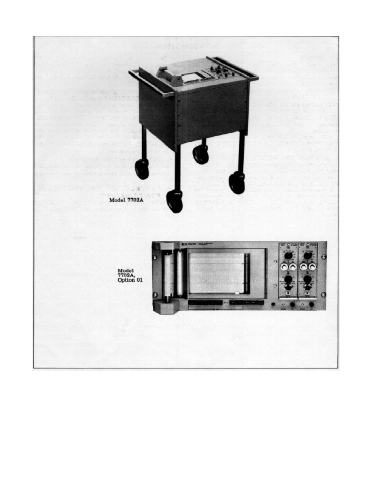
Figure 1-1. Model 7702A Recording System and Option 01
0-0
Page 7

SECTION O.
INTRODUCTION
0-1. SCOPE.
This manual describes Oscillograph Recorder RO460(V)1/U and provides instructions for operation and
maintenance. Throughout this manual, the RO-460(V)
1/U is referred to as Hewlett-Packard Model 7702B.
Refer to Section VI for differences between the 7702A
and 7702B.
0-2. INDEXES OF PUBLICATIONS.
a. DA Pam 310-4. Refer to the latest issue of DA
Pam 310-4 to determine whether there are new editions,
changes, or additional publications pertaining to the
equipment.
b. DA Pam 310-7. Refer to DA Pam 310-7 to
determine whether there are modification work orders
(MWO’s) pertaining to the equipment.
0-3. FORMS AND RECORDS.
a. Reports of Maintenance and Unsatisfactory
Equipment. Maintenance forms, records, and reports
which are to be used by maintenance personnel at all
maintenance levels are listed in and prescribed by TM
38-750.
b. Report of Packaging and Handling
Deficiencies. Fill out and forward DD Form 6 (Pack aging
Improvement Report) as prescribed in AR 70058/NAVSUPINST 4030.29/AFR 71-13/MCO P4030.29A
and DSAR 4145.8.
TM 11-6625-2751-14&P
c. Discrepancy in Shipment Report (DISREP) (SF 361).
Fill out and forward Discrepancy in Shipment Report
(DISREP) (SF 361) as prescribed in AR 55-38/NAVSUPINST 4610.33B/AFR 75-18/MCO P4610.19C
and DLAR 4500.15.
0-4. REPORTING EQUIPMENT IMPROVEMENT RECOMMENDATIONS (EIR).
EIR’s will be prepared using Standard Form SF 368,
Quality Deficiency Report. Instructions for preparing
EIR’s are provided in TM 38-750, The Army Maintenance Management System. EIR’s should be mailed
direct to Commander, US Army Communications and
Electronics Materiel Readiness Command, ATTN:
DRSEL-ME-MQ, Fort Monmouth, NJ 07703. A reply will
be furnished directly to you.
0-5. ADMINISTRATIVE STORAGE.
Administrative storage of equipm ent issued to and used
by Army activities shall be in accordance with paragr aph
2-11.
0-6. DESTRUCTION OF ARMY ELECRONICS MATERIEL.
Destruction of Army electronics materiel to prevent
enemy use shall be in accordance with TM 750-244-2.
0-1
Page 8

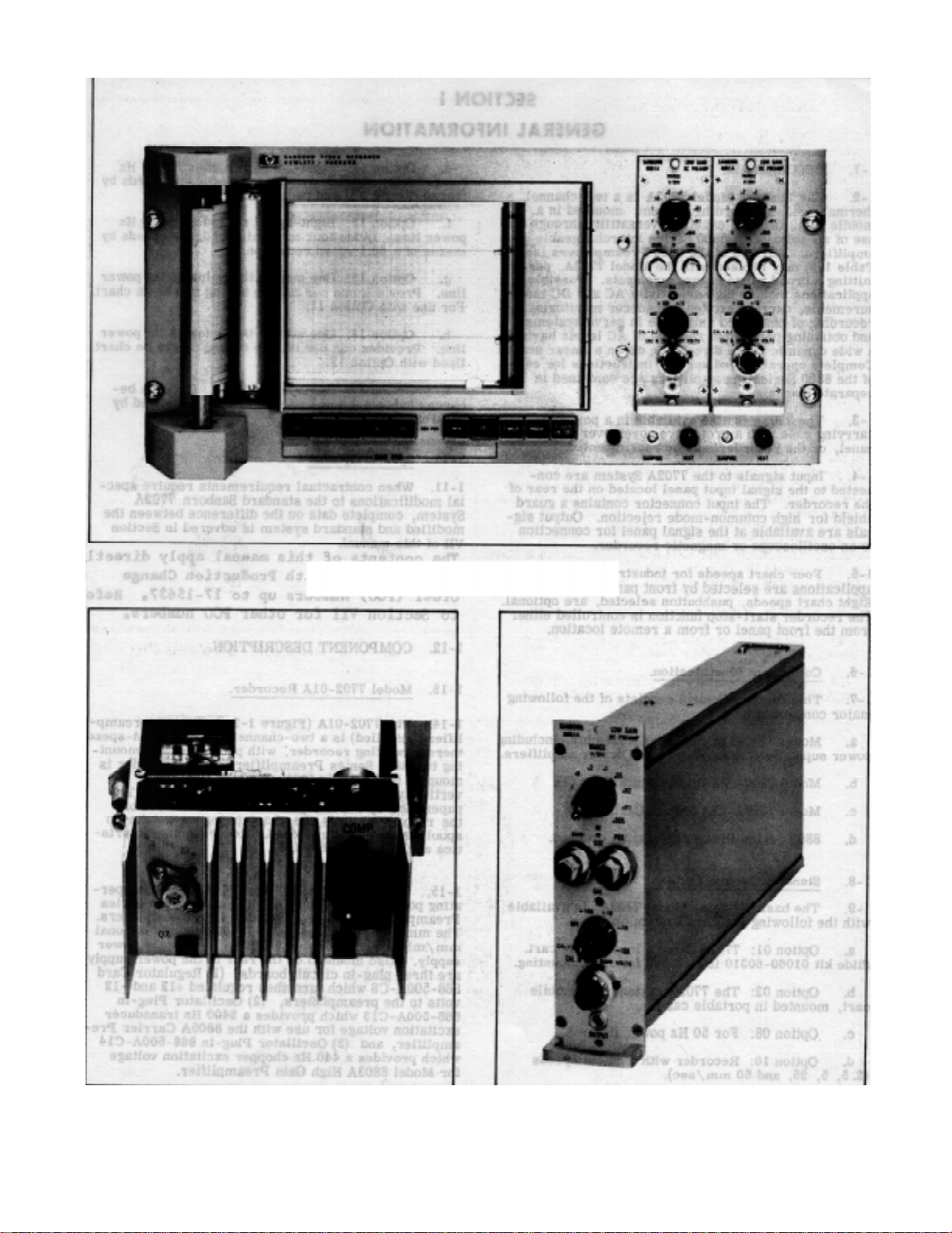
SECTION I.
GENERAL INFORMATION
1-1. DESCRIPTION.
1-2. The Sanborn Model 7702A is a two-channel
thermal writing recording system, mounted in a mobile
cart, that has excellent versatility through the use of all
solid-state 8800 Series interchangeable pre- amplifiers.
Any two of the 8800 Preamplifiers (see Table 1-3) may
be used with the Model 7702A, permitting a broad range
of measurements. ’Possible applications include high
sensitivity AC and DC measurements, carrier excited
transducer monitoring, rec ording of phase and amplitude
in servo systems, and obtaining permanent records of
AC levels having a wide dynamic range directly in dB on
a linear scale. Complete operating and service
instructions for eac h of the 8800 Ser ies Pream plif iers are
contained in separate manuals.
TM 11-6625-2751-14&P
e. Option 11: Eight-speed recorder for 60 Hz power
line. (Adds four mm/min recorder speeds by means of a
60:1 speed reduction.)
f. Option 12: Eight-speed recorder for 50 Hz power
line. (Adds four mm/min recorder speeds by means of a
60:1 speed reduction.)
g. Option 13: One minute timer for 60 Hz power
line. Provides one per minute timing marks on chart. For
use with Option 11.
h. Option 14: One minute timer for 50 Hz power
line. Provides one per minute timing marks on chart.
Used with Option 12.
i. Option 15: Auxiliary marker. Records between
channels 1 and 2 on chart paper; actuated by external
contact closure.
1-10. Special Options.
1-3. The 7702A is also available in a portable carrying
case with a protective cover over the front panel, or the
recorder may be rack mounted.
1-4. Input signals to the 7702A System are connected to the signal input panel located on the rear of the
recorder. The input connector contains a guard shield for
high common-mode rejection. Output signals are
available at the signal panel for connection to an
oscilloscope or magnetic recorder.
1-5. Four chart speeds for industrial or medical
applications are selected by front panel pushbuttons.
Eight chart speeds, pushbutton selected, are optional.
The recorder start-stop func tion is controlled either from
the front panel or from a remote location.
1-6. Component Identification.
1-7. This Sanborn System consists of the following
major components:
a. Model 7702-OlA Recorder Assembly, including
power supply for preamplifiers and driver amplifiers.
b. Model 7700-02A Driver Amplifiers (2).
c. Model 1069A-02A Mobile Cart.
d. 8800 Series Preamplifiers, as ordered.
1-8. Standard System Options.
1-9. The basic System, Model 7702A, is available
with the following standard system options:
a. Option 01: 7702A System less mobile cart.
Slide kit 01060-60310 is included for rack mounting.
b. Option 02: The 7702A System less mobile
cart, mounted in portable case.
c. Option 08: For 50 Hz power line.
d. Option 10: Recorder with medical speeds
(2. 5, 5, 25, and 50 mm/sec).
1-11. When contractual requirements require special
modifications to the standard Sanborn 7702A System,
complete data on the difference between the modified
and standard system is covered in Section VII of this
manual.
The contents of this manual apply directly
to instruments with Production Change
Order (PCO) numbers up to 17-15637. Refer
to Section VII for other PCO numbers
1-12. COMPONENT DESCRIPTION.
1-13. Model 7702-01A Recorder.
1-14. The 7702-0lA (Figure 1-2 shown with preamp
lifiers installed) is a two-channel, four or eight-speed
thermal writing recorder, with provisions f or m ounting two
8800 Series Preamplifiers. The recorder is mounted
horizontally in the 7702A Mobile Cart, or vertically in the
portable case or rack mount. The paper take-up
assembly located on the left end of the recorder stores
the chart paper on a take-up spool that is easily
removed. Recorder charac teristics are given in Table 1-
1.
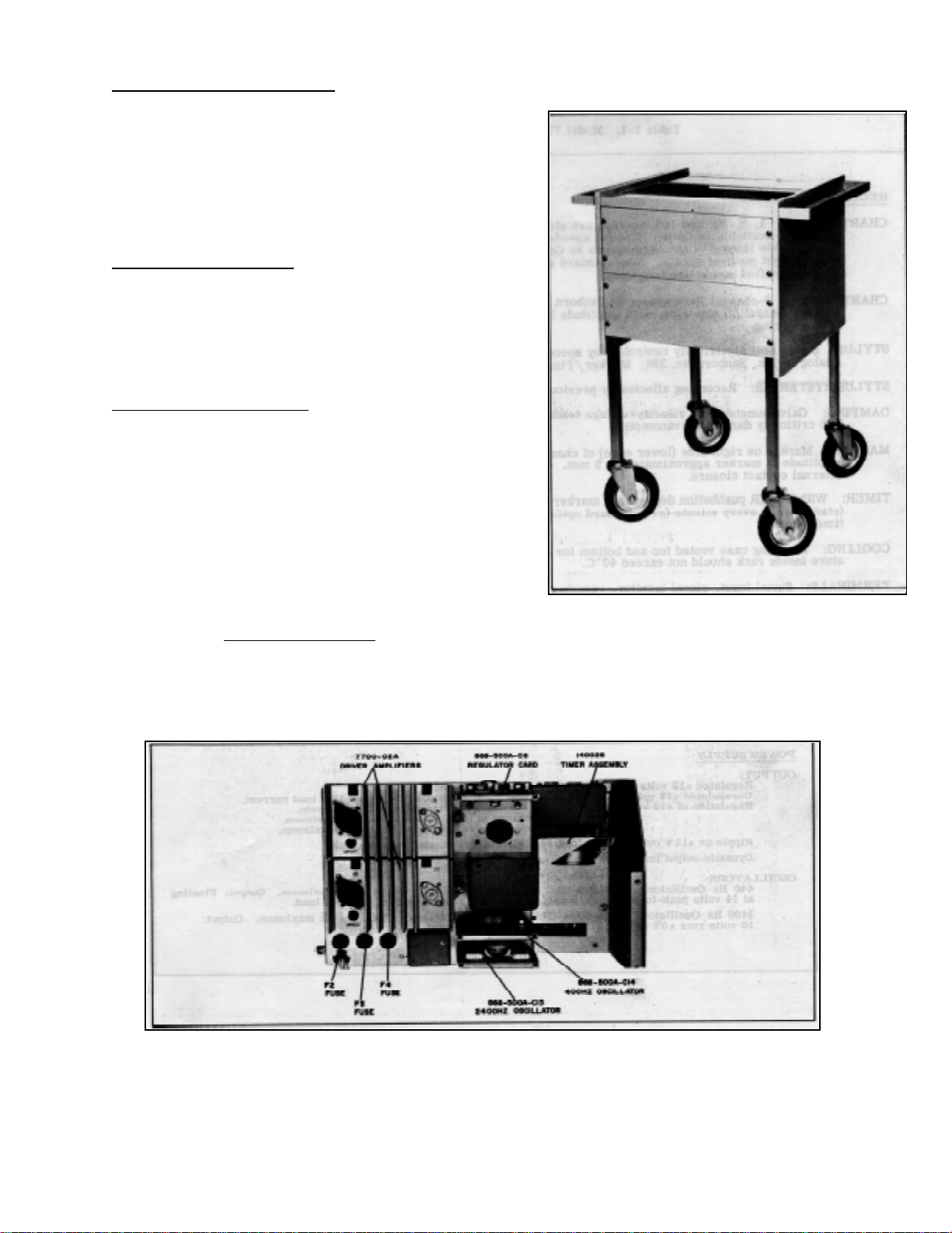
1-15. The power supply (Figure 1-6) provides oper-
ating power for the 7702-OlA Recorder, 8800 Series
Preamplifiers, and two 7700-02A Driver Amplifiers. The
mm/sec timer assembly 14002S and the optional
mm/min timer assembly 14002R plug into the power
supply. Also mounted on the rear of the power supply are
three plug-in circuit boards; (1) Regulator Card 868500A-C6 which furnishes regulated +12 and -12 volts to
the preamplifiers, (2) Oscillator Plug-in 868-500A-C13
which provides a 2400 Hz transducer excitation voltage
for use with the 8805A Carrier Pre- amplifier, and (3)
Oscillator Plug-in 868-500A-C14 which provides a 440
Hz chopper excitation voltage for Model 8803A High Gain
Preamplifier.
1-1
Page 9
TM 11-6625-2751-14&P
Figure 1-2. Model 77-01A Recorder
Figure 1-3. Model 7700-02A Driver Amplifier Figure 1-4. 8800 Series Preamplifier (8801A Shown)
1-2
Page 10
1-16. Model 7700-02A Driver Amplifier.
1-17. One plug-in driver amplifier (Figure 1-3) is
provided for each recording galvanometer. The combination of driver amplifier and galvanometer simulate
the characteristics of a galvanometer at 71% of critical
damping, by negative velocity-voltage feed- back from
the galvanometer in conjunction with a compensation
circuit in the driver amplifier. Driver Amplifier
specifications are listed in Table 1-2. 1-18.
Preamplifiers, 8800 Series.
1-19. Any of the solid-state high performance preamplifiers (Figure 1-4) for medical or industrial
applications may be installed in the recorder. Preamplifiers may be interchanged easily from the front
panel of the recorder by removing two panel mounting
screws. Preamplif iers c ontain built-in voltage cali- br ation
sources.
1-20. Model 1069-02A Mobile Cart.
1-21. The ruggedly constructed all-metal mobile cart
(Figure 1-5) is an ideal unit for many recording
applications. Metal bar handles mounted on both ends of
the cart and large diameter rubber wheels permit the
system to be moved from one location to another with
minimum effort. The line power cord, which is
permanently attached to the cart, is conveniently stored
behind the rear panel. Two AC accessory out- lets are
provided on the rear panel. A 5" high panel located on
the top of the cart and two 7" panels loc ate on the front
of the cart may be used to m ount signal panels or other
instrumentation. 1-22. System Specifications.
TM 11-6625-2751-14&P
Figure 1-5. Model 1069-02A Mobile Cart
1-23. The power, weight and dimensions for the Model
7702A are listed in Table 1-4.
1-24. Accessories provided with the System (or
available on order) are listed in Table 1-5.
Figure 1-6. 7702A System Power Supply
Figure 1-6. 7702A System Power Supply
1-3
Page 11

TM 11-6625-2751-14&P
Table 1-1. Model 7702-01A Specifications
RECORDER
CHART SPEEDS:1, 5, 20, and 100 mm/sec are standard; four additional s peeds : 1, 5, 20, 100, mm/min, available
as Option 11 (eight speeds total). Medical speeds of 2. 5, 5, 25, and 50 mm/ sec available instead of standard
speeds as Option 10. Options 10 and 11 may be combined for a total of eight medical speeds. Non-standard
speeds available on special order. Speed regulation 1% at specified power line frequency.
CHART PAPER: 2-channel Permapaper( Sanborn No. 651-52. Paper width 5" (127 mm). Each recording
channel 50 mm wide, with amplitude lines spaced 1 mm apart. Timing lines also have 1 mm spacing.
STYLUS: Stylus heat electrically controlled by speed selector and also adjustable by front panel control. Analog
Stylus, Sanborn No. 398; Marker/Timer Stylus, Sanborn No. 411-10.
STYLUS HYSTERISIS: Recording affected by previous signals by less than 0O. 1 divisions. DAMPING:
Galvanometer with velocity-voltage feedback in combination with drive circuit simulates a 71% critically
damped galvanometer.
MARKER: Marker on right side (lower edge) of chart is standard; center margin marker optional; amplitude of
marker approximately 1. 5 mm. Marker is operated by front panel switch or by external contact closure.
TIMER: With TIMER pushbutton depressed, marker pulse occurs on right side of chart every second (standard) or
every minute (see standard option, Paragraph 1-8). Marker operation over-rides
timer signal.
COOLING: Mounting case vented top and bottom for convection cooling. For rack mounting, temperature inside rack
should not exceed 40’C.
TERMINALS: Signal input, signal monitor, remote chart drive start-stop, and servo reference input
located on rear.
FRONT PANEL CONTROLS: Individual STYLUS heat adjustments; individual galvanometer DAMPING
screwdriver adjust; pushbutton TIMER, MARK and POWER switches; pushbutton SPEED
selector switches.
POWER SUPPLY
OUTPUT:
Regulated +12 volts at 500 milliamperes maximum, each polarity.
Unregulated ±18 volts at 1/2 ampere maximum, each polarity, less ±12V load current.
Regulation of ±12 volt output a) with 20% change in line voltage 1/o maximum.
b) with change in load, 0 to full load 2% maximum.
c) with change in temperature 3 mV/C' maximum.
Ripple on ±12 V output at full load 10 millivolts maximum, peak-to-peak.
Dynamic output impedance of +12V output: 1/2 ohm, DC to 10 kHz.
OSCILLATORS:
440 Hz Oscillator, 868-500-C14: Frequency Stability: 440 Hz ± 5% maximum. Output: Floating
at 14 volts peak-to-peak at 1/2 watt. Amplitude stability +2% of constant load.
2400 Hz Oscillator, 868-500A-C13: Frequency Stability: 2400 Hz + 2% maximum. Output:
10 volts rms ±5% at 50 milliwatts maximum. Grounded center tap.
1-4
Page 12

TM 11-6625-2751-14&P
Table 1-2. Model 7700-02A Specifications
DRIVER AMPLIFIER
FREQUENCY RESPONSE: DC to less than 3 dB down at 125 Hz for chart deflection of 10 divisions pp.
Damping set for 4% overshoot with a 10 division pp square wave.
SENSITIVITY: ±2. 5 volts nominal for full recording chart width deflection.
NOISE: Less than 0. 1 division pp with zero signal input.
RESPONSE TIME: Less than 5 msec, 10% to 90% for a 10 division square wave with damping set for 4%
overshoot.
DRIVER INPUT IMPEDANCE: (preamplifier output loading) 5K ohms, ±5%, single-ended, with signal
ground isolated from chassis ground.
LINEARITY:
Method 1: After setting mechanical zero of stylus within 0o. 1 division of chart center and calibrating for zero error at center scale and +20 divisions, error is less then ±0. 25 divisions at any point
on printed coordinates.
Method 2: After setting mechanical zero of stylus within +1 division of chart center and calibrating
for zero error at lower and upper ends of printed coordinates, error is less than t0. 5 division at
any point on the scale.
GAIN STABILITY (after one hour warmup): Temperature: Less than 0. 25%/10'C, 20° to 40°C.
Line Voltage: 0. 5%, 103 to 127 volts.
ZERO DRIFT (driver amplifier input shorted and after one hour warmup): Temperature: Less then
0.25 div/10°C, 20° to 40°C. Line Voltage: 0.1 div, 103 to 127 volts. Paper Drift: Less than
0.25 div.
LIMITING: Electrical limiting in drive circuit at approximately 125% of full scale. Stylus is mechani-
cally limited by spring stops.
Table 1-3. 8800 Series Preamplifiers
Preamplifier Description Sensitivity
8801A Low Gain DC Preamplifier 5 mV/div
8802A Medium Gain DC Preamplifier 1 mV/div
8803A High Gain DC Preamplifier 1 µV/div
8805A Carrier Preamplifier (with calibrated CAL factor) 10 µV/div
8806B Phase Sensitive Demodulator 0. 5 mV rms/div
8807A AC-DC Converter 1 mV rms/div (at x20
scale expansion)
8808A Log-Level Preamplifier 100 µV rms
8809A Special Purpose DC 20 mV/div
NOTE: All preamplifiers except 8806B and 8808A feature calibrated zero suppression.
1-5
Page 13
TM 11-6625-2751-14&P
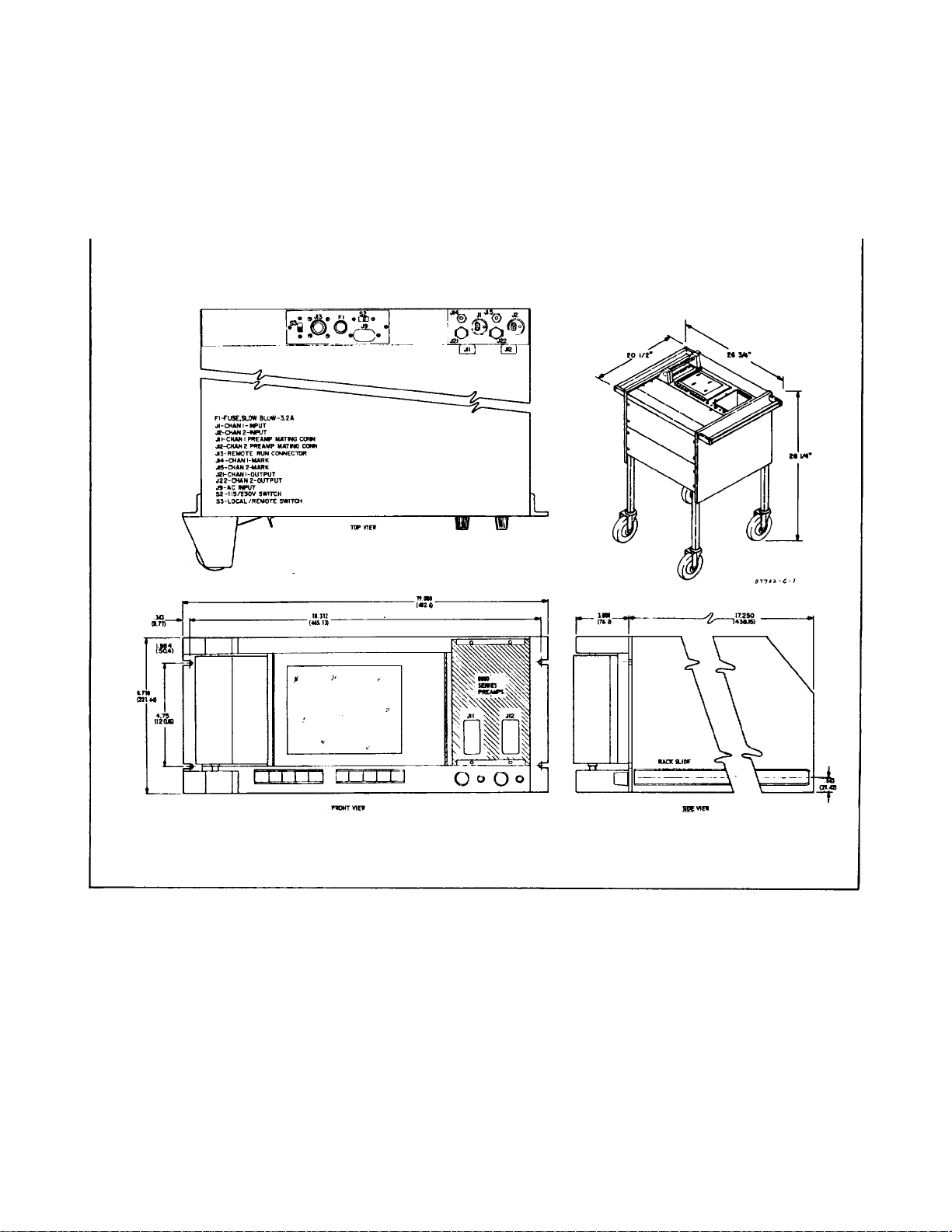
Table 1-4. System Specifications
POWER: 115/230 volts ± 10%, 60Hz, approximately 200 watts. 115/230 volts ±10%, a50 Hz, specify Option 08.
WEIGHT: 130 lb. (59kg), includes 1069-02A Mobile Cart and two preamplifiers.
DIMENSIONS: (see illustrations below)
1-6
Page 14

TM 11-6625-2751-14&P
Table 1-5. System Accessories
Qty. Description Number
2 Signal Input Connector 10G3-34FW
2 Signal Output Connector 10B9-5MW
1 Remote Run Connector 10A5-3MW
1 Remote Run Connector Cable Clamp 10OA5-lFWA
1 Remote Marker Plug 10G2-22MW
1 Power Cord 3-wire 10G3-42MFW
1 Adapter, 3-wire to 2-wire 10G3-11MFW
2 Fuse 0.5 Amp Slo Blo (F2, F3) 26B-4
1 Fuse 0.8 Amp Slo Blo (Fl 220V) 26B-6
1 Screwdriver 37A-10A
2 Record Spool 94-104P1
1 Spline Wrench 100-600-C5
2 Galvanometer Stylus 398
1 Roll, Permapaper 651-52
1 Stylus Pressure Tester 14015A
1-7
Page 15

SECTION II.
INSTALLATION
TM 11-6625-2751-14&P
2-1. INTRODUCTION.
2-2. This section contains information on unpacking, inspection, repacking, and installation.
2-3. INITIAL INSPECTION.
2-4. Mechanical Inspection.
2-5. If external damage to the shipping carton is
evident, ask the carrier’s agent to be present when the
System is unpacked. Check the System for external
damage such as broken controls or connectors, and
dents or scratches on the panel surface. If damage is
found, refer to Paragraph 2-8 for recommended claim
procedure and repacking information. If the shipping
carton is not damaged, check the cushioning material
and note any signs of severe stress as an indication of
rough handling in transit. Retain the packaging material
for possible future use.
2-6. Electrical Check.
2-7. Check the electric al performance of the Sys- tem
as soon as possible after rec eipt; see Section V for the
recommended performance checks. The checks will
verify that the System is operating within the
specifications listed in Table 1-1. This check is a good
test procedure for incom ing quality control inspection and
for an operational check after repairs or adjustments
have been made.
2-8. CLAIMS AND REPACKAGING.
2-9. Claims for Damage.
2-10. If physical damage is evident or if the System
components do not meet specifications when received,
notify the carrier and the nearest Hewlett-Packard
Sales/Service Office (see list in back of manual). The
Sales/Service Office will arrange for repair or
replacement of the unit(s) without waiting for settlem ent
of the claim against the carrier.
2-11. Repacking for Shipment or Storage.
2-12. If the instrument is to be shipped to a HewlettPackard Sales/Service Office, attach a tag showing
owner and address, instrument model and serial number,
and the repair required. The original ship- ping carton
and packaging material, with the exc eption of accor dionpleated pads, may be reusable. The Hewlett-Packard
Sales/Service Office will also pro- vide information and
recommendations on materials to be used if the original
packaging material is not available or not reusable.
Materials should include, (1) a double-walled carton
(check with a freight carrier for test s tr ength requir ed), ( 2)
heavy paper or sheets of cardboard to protect all
instrument surfaces ; use extra m aterial ar ound projec ting
parts of the instrument, (3) at least four inches of tightlypacked shock-absorbing material surrounding the
instrument. Close the package securely with heavy paper
tape.
2-13. INSTALLATION.
2-14. The 7702A System is ready for use after removal from the packing case. No packing materials are
contained in the recorder section. T he system is shipped
without Permapaper mounted in the recorder; see paper
loading instructions in Section III.
2-15. Environment.
2-16. System location should be reasonably free from
vibration, dust, corrosive or explosive vapors or gases,
extremes of tem perature, humidity, etc. The floor should
be level and must supply support for all four wheels of
the System. For a cabinet mounted installation, allow
sufficient room at the f ront for operation with any part of
the System extended forward, and at the rear for
servicing with access door open.
2-17. The 7702A System requires no additional cooling. For rack mounting (7702A, Option 01), the tem per-
ature inside the rack cabinet should not exceed 40°C.
2-18. Check that the power line voltage, voltage regulation, power capacity, frequency, and frequency
stability are suitable for the requirements of the Sys- tem.
The time-axis accuracy of the recording will be directly
dependent upon the frequency stability of the power line.
2-19. Rack Mounting Instructions.
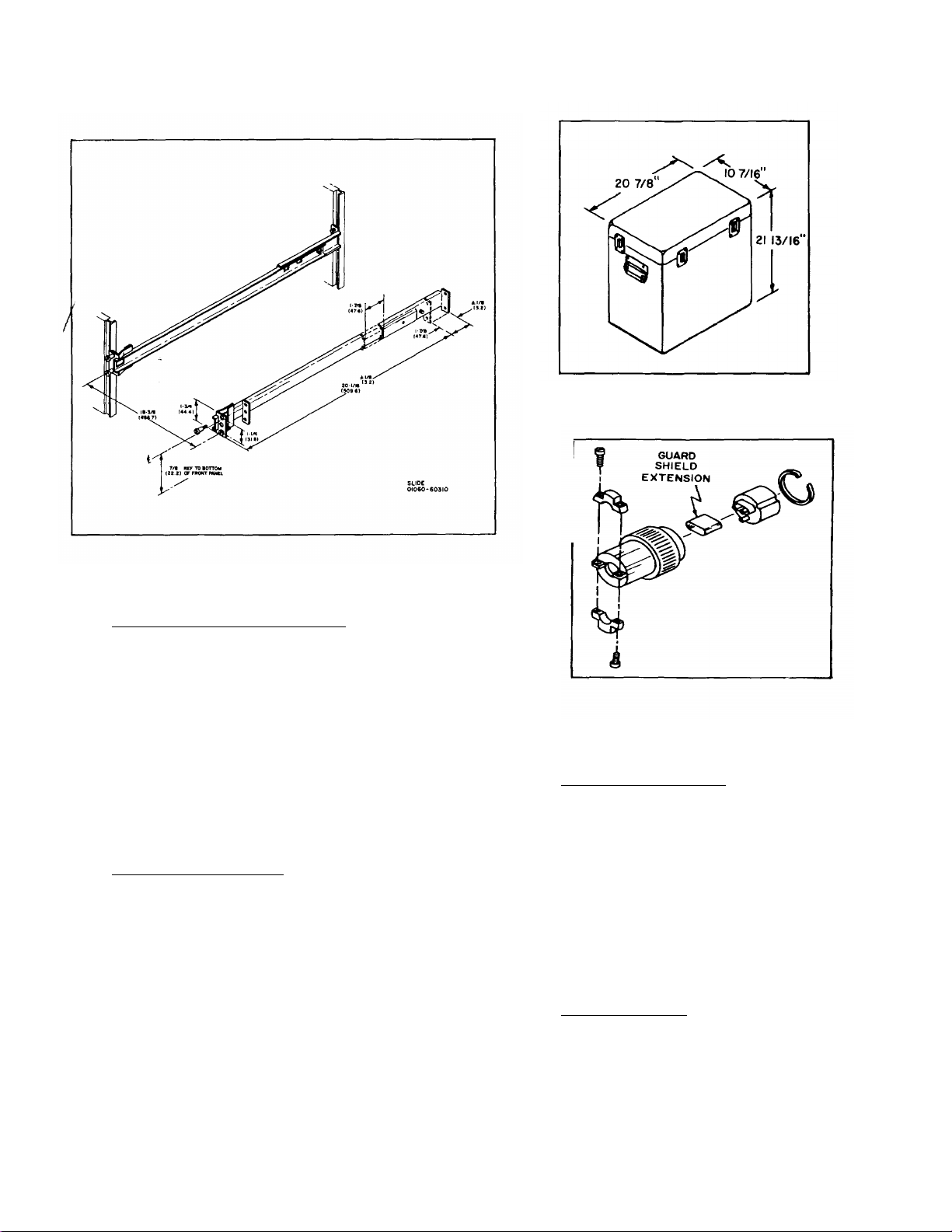
2-20. Model 7702A, Option 01, consists of the Model
7702-0lA Recorder, with Slide Kit 01060-60310, for
mounting in a cabinet. To install the recor der, attach the
slides to the side rails of the c abinet. Figure 2-1 shows
the location of the mounting holes for the slide kit. Slide
the recorder into the side rails and fasten the recorder in
place with panel screws.
2-21. System in Portable Case.
2-22. Model 7702A, Option 02, consists of the 7700OlA Recorder mounted in a portable transit case 770214A, shown in Figure 2-2. Two side handles are used f or
carrying the case. A removable metal c over protects the
recorder front panel when being transported. Signal input
and power cables are connected to the s ystem through
an open- ing in the rear of the case.
2-23. AC Power Requirements.
2-24. The Model 7702A may be operated from an ac
source of 155 or 230 volts (+10%), 60 Hz. Model 7702A,
Option 08, operates on 115 or 230 volts (+10%), 50 Hz.
With the instr ument power cord disconnected, move the
slide switch located on the rear panel (see Figure 3-3)
until the desired voltage numbers (115 or 230) are
visible. A narrow blade screwdriver may be used to
operate the switch. Fuse F1 should be 1.5 amp slowblow for 115 volt operation, or 0.8 amp slow-blow for 230
volt operation.
2-1
Page 16
TM 11-6625-2751-14&P
Figure 2-2. Portable Case
Figure 2-1. Slide Kit - 01060-60310
2-25. Three-Conductor Power Cable. To protect
operating personnel, the National Electrical
Manufacturers’ Association (NEMA) recommends that
the instrument and cabinet be grounded. The Model
7702A is supplied with a three-conductor power cable
which, when plugged into an appropriate receptacle,
grounds the instrument to the power line ground. The
round pin on the power cable is the ground c onnection.
To retain this protection feature when operating the
instrument from a two-contact outlet, use the 10G311lMFW three-conductor to two- conductor adapter
(supplied as an accessory with the instrument) and
connect the green wire to the outlet box.
2-26. Input Signal Connections.
2-27. The 8800 Preamplifier signal input circuits may
be divided into two types, guarded and non- guarded.
Preamplifiers having a guard shield terminal (8803A,
8806B, 8807A) feature a high comm on- mode rejection
ratio. To obtain the high rejection ratio, the signal input
cable must contain a guard shield. Non-guarded
preamplifiers (8801A, 8802A, 8805A, 8808A, 8809AY do
not require a guard shield in the signal input cable.
Additional information on input signal connections is
contained in the preamplifier instruction manuals.
Figure 2-3. 10G3-34FW Connector
2-28. Signal Input Connectors.
2-29. Two signal input connectors, 10G3-34FW(see
Figure 2-3), are supplied as access ories with the system.
The connectors plug into the signal input jac k s J 1 and J2
on the rear of the recorder. J1 signals (channel 1) are
internally cabled to the left pre- amplifier (viewed from the
front of the recorder) and r ecorded on the upper channel
of the chart paper. J2 input signals are cabled to the right
preamplifier, and are recorded on the lower channel of
the chart
paper.
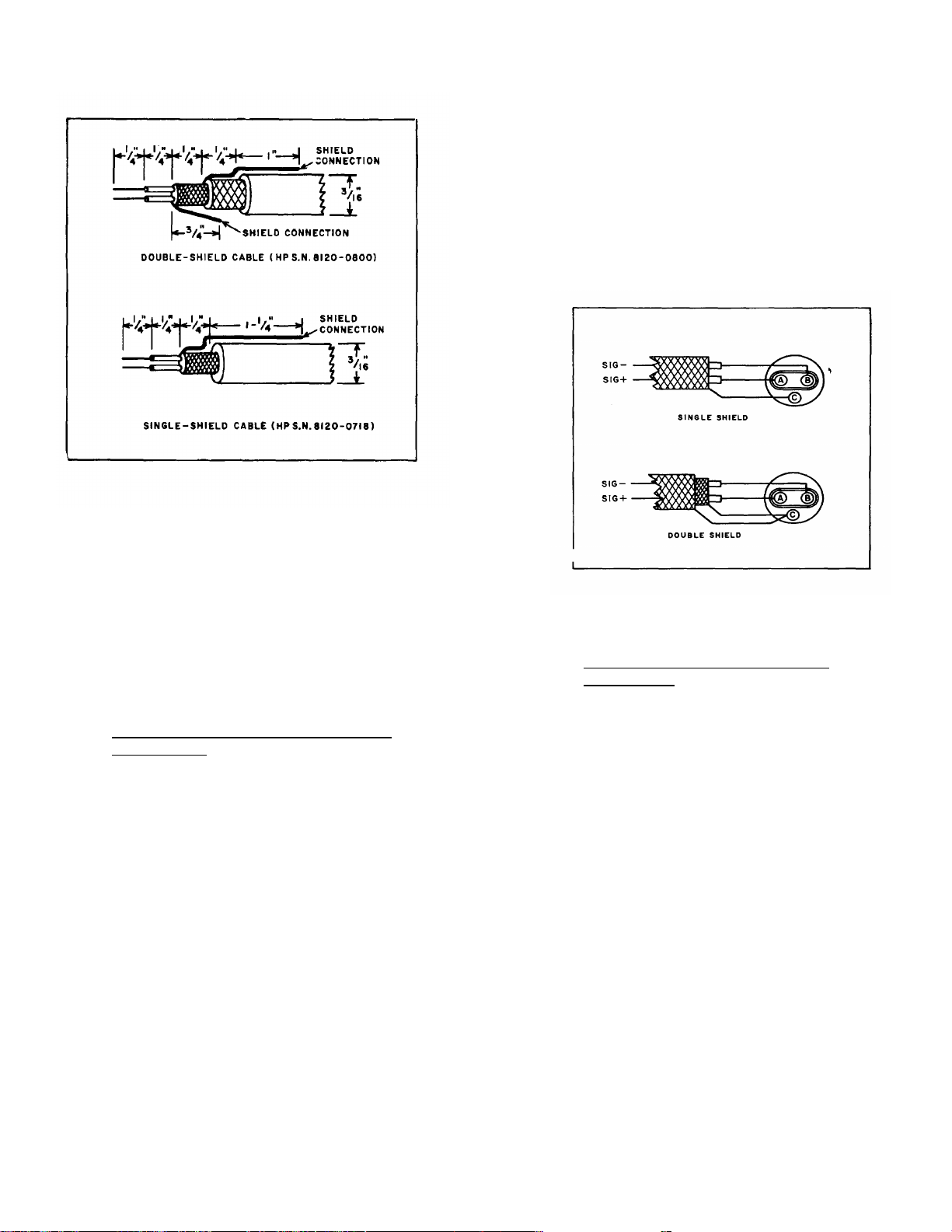
2-30. Signal Input Cable.
2-31. Two conductor shielded cable 3/16" O.D., with
single or doubled braided shield is required for connecting the signal source to the input connectors. See
Figure 2-4 for cable preparation information.
2-2
Page 17
TM 11-6625-2751-14&P
NOTE
Single conductor cable can be used
with the 8808A and 8809A Preamplifiers, which have single-ended input
circuits. Connect the cable center
conductor to pin A, and the shield to
pin B.
Figure 2-6. Input Connector Wiring, Guarded
2-32. Preamplifiers which have a guard shield input
terminal use double shielded cable for a fully guarded
input circuit. The inner shield connects to the common mode potential of the signal source to reduce
capacitive and resistive currents between the signal
conductors and ground. The outer shield is grounded,
to prevent capacitive coupling of the common mode
potential on the inner shield into other circuitry. In
many cases, the second (outer) shield may be omitted with no deterioration in performance.
2-33. Input Connector Wiring for Non-Guarded
Preamplifiers.
2-34. The following instructions are for wiring the
input connector using either single or double shielded
cable.
a. Loosen the 10G3-34FW connector cable clamp
screws.
b. Slide the dressed end of the cable into the
cable clamp and through the connector shell.
c. Remove and store the guard shield extension.
d. Solder the cable center conductors to connector pins A and B. See Figure 2-5.
e. Solder the cable shield(s) to pin C.
f. Press the connector block carefully into the
connector shell, allowing the cable to pass through
the connector clamp.
g. Insert the retaining ring.
h. Tighten the cable clamp screws.
Figure 2-5. Input Connector Wiring, Non-Guarded
2-35. Input Connector Wiring for Guarded
Preamplifiers.
2-36. The following instructions are for wiring the
input connectors using either single or double shielded
cable.
a. Loosen the 10G3-34FW connector cable clamp
screws.
b. Slide the dressed end of the cable into the
cable clamp and through the connector shell.
c. Slide the guard shield extension down over the
cable shield(s) and onto the guard socket.
d. Solder the cable center conductors to pins A
and B. See Figure 2-6.
e. For single shield cable, solder the cable shield
to the guard shield extension.
f. For double shield cable solder the inner
(guard) shield to the guard shield extension, and solder the outer shield to pin C. Check that shields are
not shorted to each other or to the connector shell.
g. Press the connector block carefully into the
connector shell, allowing the cable to pass through
the cable clamp.
h. Insert the retaining ring.
i. Tighten the cable clamp screws.
2-3
Page 18
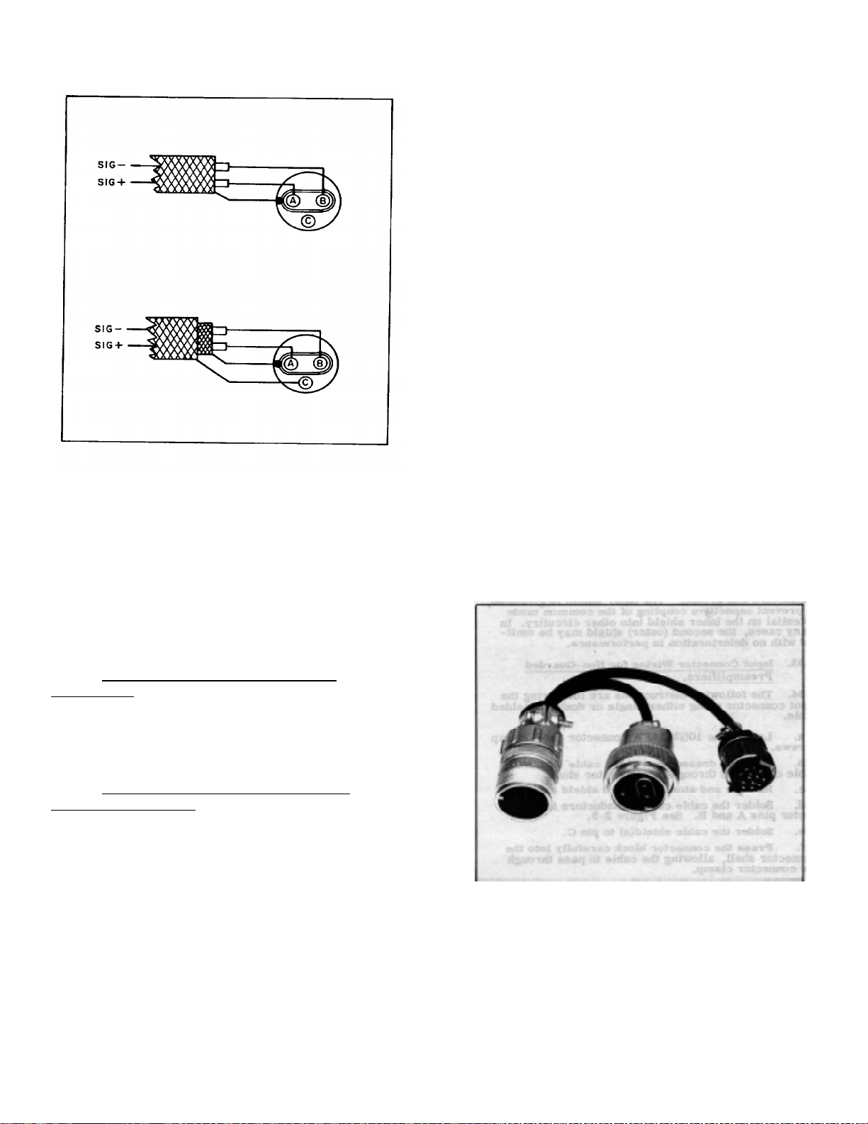
Figure 2-6. Input Connector Wiring, Guarded
2-37. 8805A CARRIER PREAMPLIFIER INPUT
CABLES.
2-38. Carrier preamplifier operation requires both a
non-guarded signal input cable and a carrier refer- ence
cable, connected between the strain gage or transducer
and the 7702A System. A cable assembly for use with
Sanborn transducers is shown in Figure 2-7. Cables for
other applications are assembled
following the instructions in Paragraph 2-41.
TM 11-6625-2751-14&P
(2) Connect the cable to jack J1 (for channel 1)
or jack J2 (for channel 2), located on the rear panel of
the recorder.
b. Carrier Reference Cable. (1) Connect a twoconductor shielded cable to the 10B9-5MW connector,
supplied as an accessory with the system. Solder the two
cable conductors to pins A and B, cable shield to pin E.
(2) Connect the cable to jack J21 (for channel 1)
or jack J22 (for channel 2) located on the rear panel of
the recorder.
2-43. 8806B PHASE SENSITIVE DEMODULATOR
SIGNAL CABLES.
2-44. Demodulator preamplifier operation requires both
a signal input cable and a servo reference cable.
Construction of the cables is described below.
2-45. Construct the two-conductor signal input cable
with a guard shield (see Paragraph 2-
35)
if a high
common-mode rejection is desired. If high commonmode rejection is not required, the input cable is wired
with an unguarded, single-shield cable (see Paragr aph 2-
33). Connect the signal input cable to J1 (channel 1) or
J2 (channel 2).
2-46. Construct the servo reference cable using twoconductor shielded cable and the 10B9-5MW con- nector
supplied as an accessory with the system. Normal
connection uses a single-shielded cable, in a nonguarded circuit. Solder the "+" servo ref erence signal to
pin K, and the "-" servo reference to pin F. Connect the
servo reference cable to J21 (c hannel 1) or J22 (channel
2), located on the rear panel of the 7702A Recorder.
2-39. Cable Assembly for use with Sanborn
Transducers.
2-40. Use the cable assembly no. 5060-4602 (Figure
2-7) to connect Sanborn Series 267, 268 and 270 Series
Transducers to the 7702A System. T his Y-cable contains
both a signal input cable and a carrier reference cable.
2-41. Instructions for Assembling Signal Input
and Reference Cables.
2-42. Signal input and carrier reference cables for
carrier preamplifier applications described in the
instruction manual IM-8805A-1 are assembled as follows:
a. Signal Input Cable.
(1) Connect a two-conductor shielded cable to the 10G334FW connector, supplied as an accessory with the
system. Solder the two cable conductors to pins A and B,
cable shield to pin C (see Paragraph 2-33).
2-4
Page 19
2-47. SIGNAL MONITOR CONNECTIONS.
2-48. The preamplifier single-ended output s ignals are
available at J21 (channel 1) and J22 (channel 2), located
on the rear panel of the recorder. Signal output is pin D,
signal common is pin H. For 8803A High Gain
Preamplifier, signal out is pin A, signal com mon is pin B.
The 10B9-5MW mating connectors are supplied as
accessories with the system.
2-49. REMOTE RECORDER OPERATION.
2-50. The 7702A Recorder chart drive ST ART- STOP
function and the MARKER function can be con- trolled
from a rem ote location. The circuits required ar e shown
in Figures 2-8 and 2-9.
2-51. Remote Chart Drive START-STOP Control.
2-52. Construct the circuit shown in Figure 2-8.
The 10A5-3MW remote run connector and the 10A5lFWA cable c lamp are supplied as accessories with the
system. Any length of four conductor cable may be used.
The remote run circuit plugs into the J13 jac k on the rear
panel of the recorder.
Figure 2-8. Remote Run Circuit Diagram
2-53. To operate the recorder using the REMOTE
RUN circuit, switch the LOCAL-REMOTE switch S3
located on the rear panel of the recorder to the
REMOTE position and press the desired speed pushbutton on the recorder front panel. Operate the
remote STANDBY-RUN switch to control chart drive.
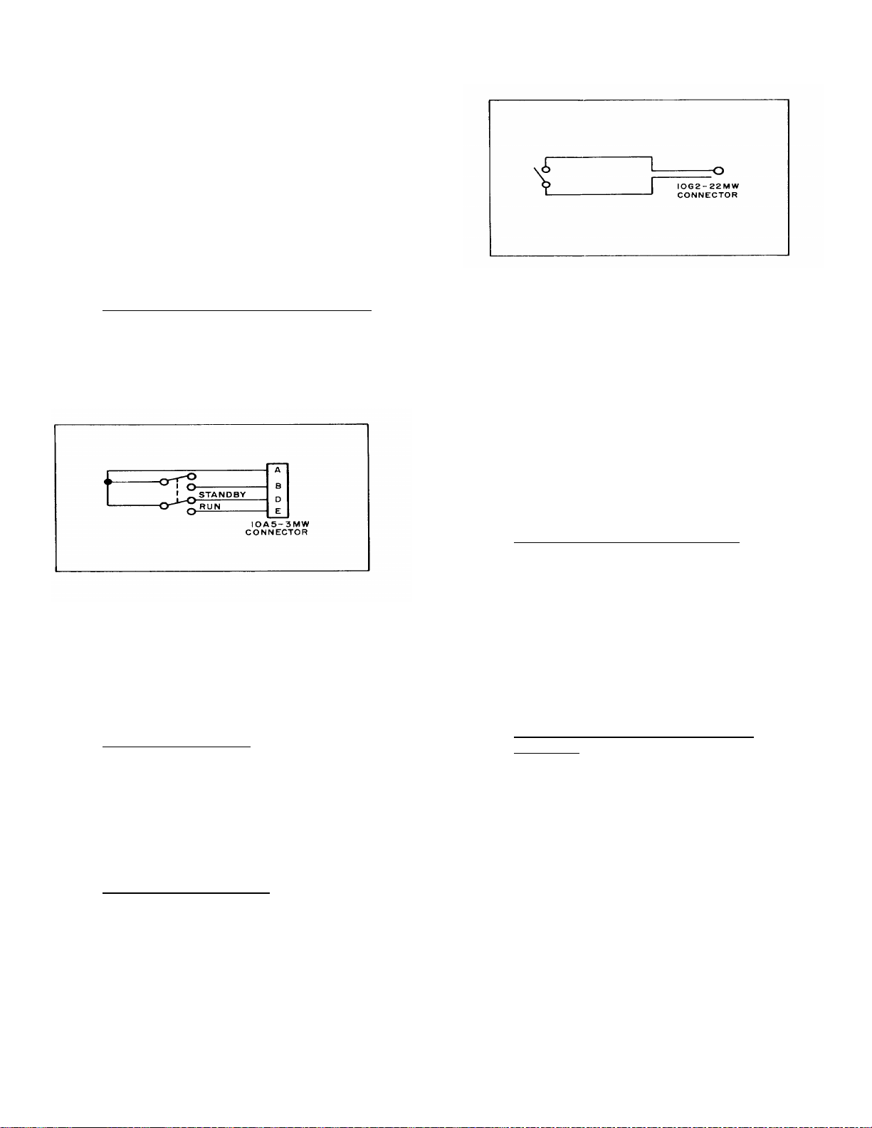
2-54. Remote Marker Control.
2-55. The marker may be operated from a remote
location or from the recorder front panel. To operate the marker from a remote location, construct
the circuit shown in Figure 2-9. The connector
10G2-22MW is supplied as an accessory with the
system. Any length of cable may be used.
2-56. The Remote marker circuit plugs into the J15
jack on the rear panel of the recorder.
2-57. Auxiliary Marker Operation.
2-58. To operate the auxiliary marker, available
as 7702A Option 15, construct a switch circuit as
shown in Figure 2-9. Plug the switch into the auxiliary marker Jack J14, located on the rear panel of
the recorder.
TM 11-6625-2751-14&P
Figure 2-9. Remote Marker Circuit Diagram
2-59. INITIAL SYSTEM CHECK.
2-60. The following procedures are designed to check
the recorder drive, marker, timer, and re- mote control
functions. To check the operation of the preamplifiers,
refer to the instruction manual for the 8800 Series
preamplifiers installed in the system.
2-61. Review the installation process, checking the
cables and connectors. Tighten all connections. Check
that the S3 power line switch (see Figure 3-3) indicates
the correct voltage. The recording system may be
damaged if the switch is set to the incorrect voltage
range.
2-62. Install a roll of Permapaper in the recorder,
following the instructions in Figure 3-4.
2-63. To Check Recorder Drive Functions.
a. Press the POWER pushbutton. The panel
indicator lamp will light.
b. Press the MM/SEC pushbutton.
c. Press each of the four speed-pushbuttons.
Check for proper paper travel at each speed selected. If
recorder is equipped with mm /min speeds, Option 11 or
Option 12, press MM/MIN pushbutton. Press each of the
four speed-pushbuttons, check ing for proper paper travel
at each speed selected.
d. Adjust the stylus HEAT controls for a dense,
well-defined baseline.
2-64. To Check Recorder Marker and Timer
Functions.
a. Press the MARKER pushbutton. A mark will be
recorded on the lower edge of the chart. To check
remote marker operation, connect the circuit shown in
Figure 2-9 to J15.
b. Press MM/SEC and TIMER pushbuttons. A
one per second timing mark will be recorded on the lower
edge of the chart. Press TIMER again to re- lease
pushbutton. If system is equipped with mm/min timer,
Option 13 or 14, press MM/MIN and T I MER pushbuttons .
A one per minute timing mark will be recorded on the
chart.
2-5
Page 20
TM 11-6625-2751-14&P
Figure 2-10. System Controls
2-6
Page 21
SECTION III.
OPERATION
3-1. INTRODUCTION.
3-2. The basic function of the 7702A System is to
produce graphic tracings on two-channel thermal sensitive Permapaper, using the heated stylus recording
technique. Input signals are amplified by the 8800 Series
signal conditioning preamplifiers, and displayed on 50
mm-wide channels on the chart paper. Preamplifiers
contain amplitude calibration standards which can be
recorded on the chart paper when desired. The chart
paper time scale unit is adjus table in fixed steps by the
setting of the pushbutton chart speed controls. Standar d
recorder speeds provide time scale calibration ranging
from 1 m m/sec to 100 mm/sec. W ith Option 11 (60 Hz)
or Option 12 (50 Hz), four chart speeds are added which
provide time scale calibration from 1 mm/min to 100 mm/
min.
TM 11-6625-2751-14&P
3-3. CONTROLS AND CONNECTORS.
3-4. Front and rear panel controls and c onnec tors ar e
shown in Figures 3-2 and 3-3.
3-5. OPERATING PROCEDURES.
3-6. The 7702A System is ready for use following
installation, discussed in Section II. Figure 3-4 describes
the Permapaper loading procedure, and Figure 3-5
provides step-by-step operating instructions, for normal
operation of the instrument. Figure 3-6 provides
instructions for rem ote operation of the c hart drive s tart stop and marker functions.
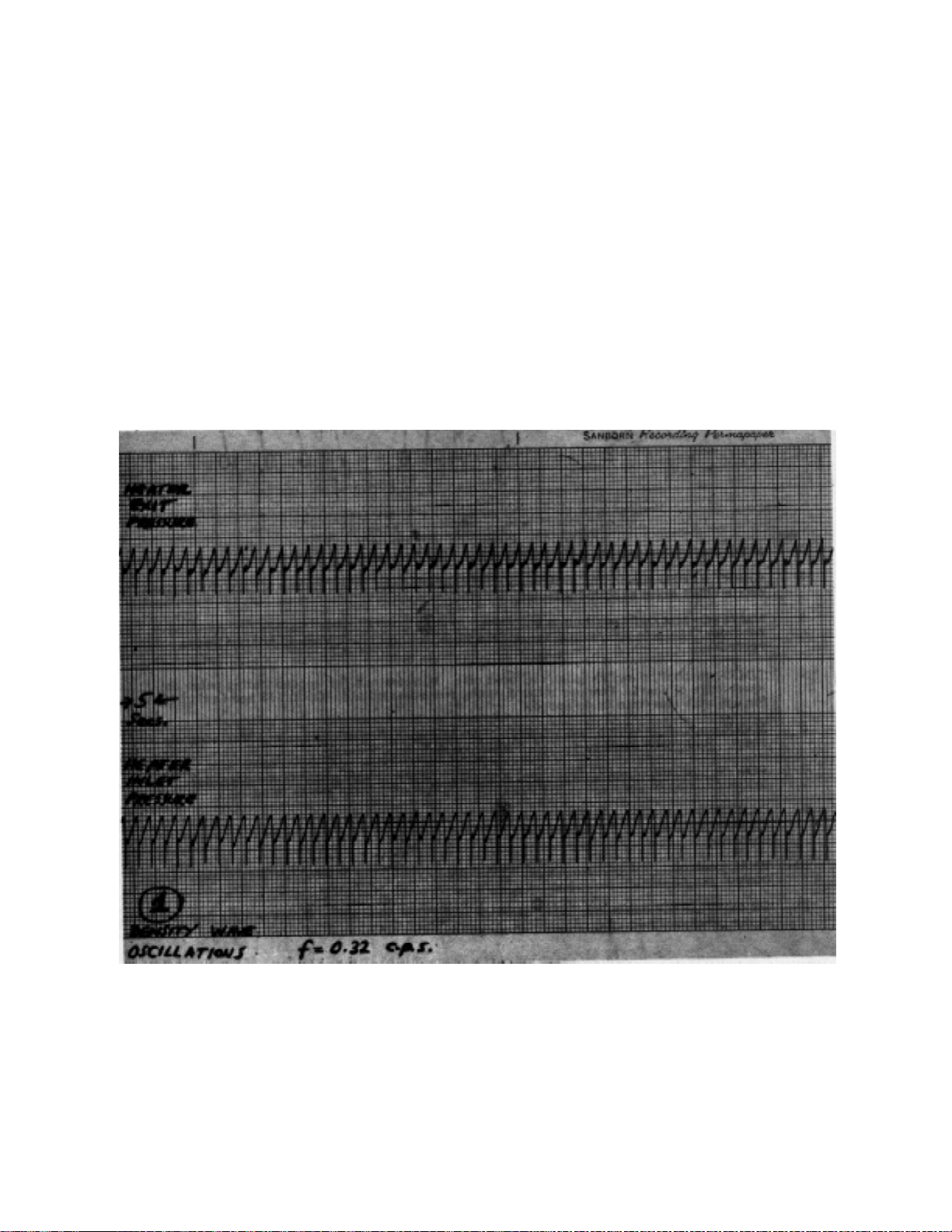
Figure 3-1. Typical 2-Channel Recording
3-1
Page 22
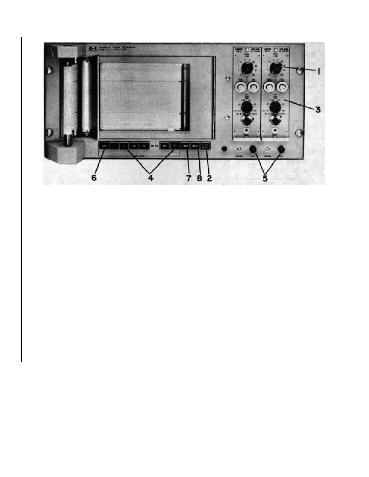
TM 11-6625-2751-14&P
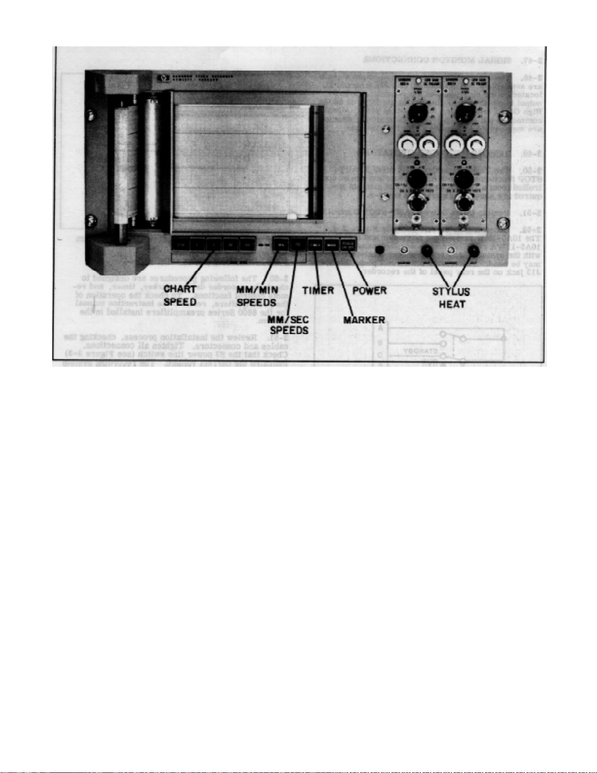
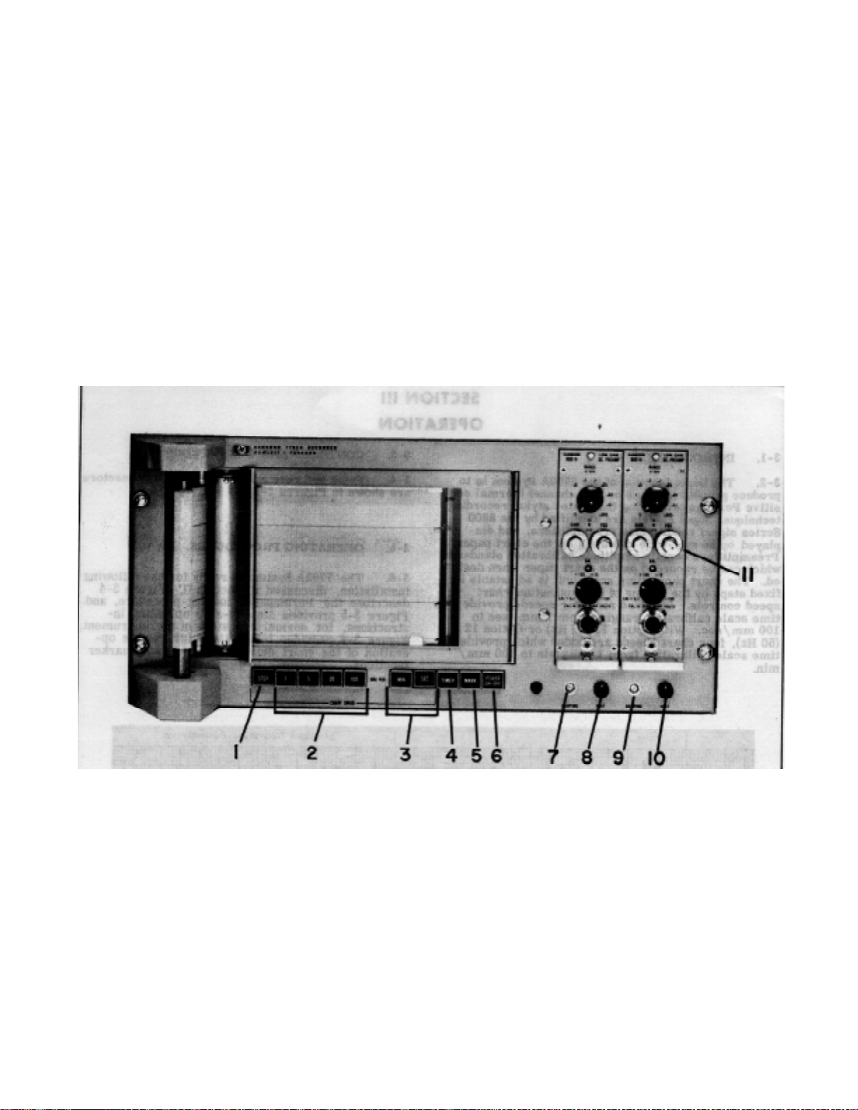
1 STOP pushbutton switch (momentary). Controls chart drive.
2 CHART SPEED pushbutton switches select chart speed. Pressing any of four pushbuttons starts chart drive at
speed selected.
3 MM/SEC-MM/MIN pushbutton switches. Selects mm/sec drive speeds for standard recorder. Selects mm/min
drive speeds when Option 11 or Option 12 is installed in recorder.
4 TIMER pushbutton switch (push on, push off). Initiates one per second timing pulse on lower edge of chart. One
per minute timing pulse is available (Option 13 and Option 14) for use with mm/min drive speeds.
5 MARK pushbutton switch (momentary). Controls operation of marker at lower edge of chart. Reference mark is
recorded when pushbutton is pressed.
6 POWER pushbutton switch (push on, push off). Controls line power to the recorder. Indicator lamp to the right of
the power switch lights when the power is on.
7 9 DAMPING controls. Adjusts the amount of feedback from the galvanometer windings to the driver amplifiers, to
obtain optimum galvanometer pulse response. One control per channel
8 10 HEAT controls. Adjusts amount of stylus heat to obtain the desired trace intensity. One control per channel
11 PREAMPLIFIER controls. Refer to the preamplifier instruction manuals for a description of the panel controls.
Figure 3-2. Front Panel Controls
3-2
Page 23
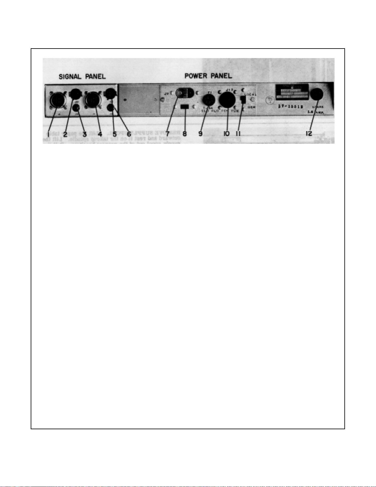
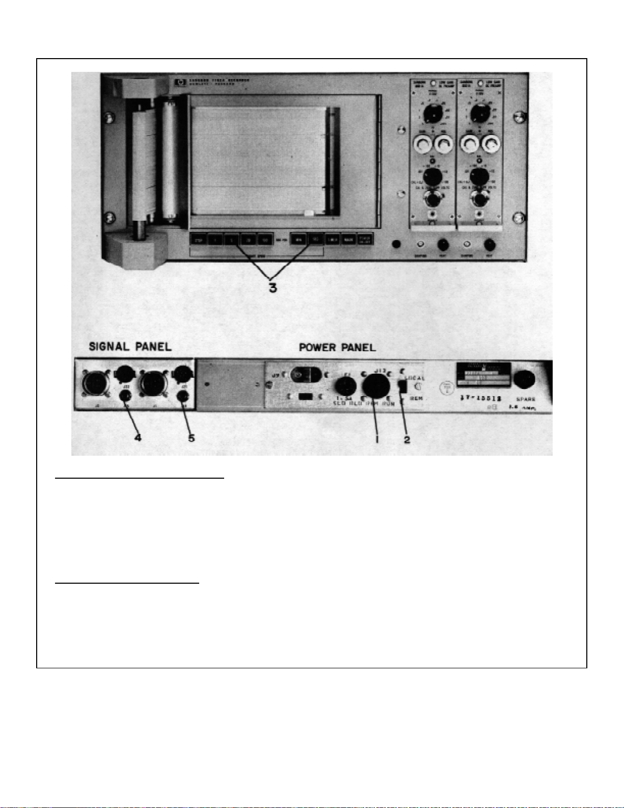
TM 11-6625-2751-14&P
1 SIGNAL INPUT connector. Input for Channel 2.
2 SIGNAL MONITOR connector. Output of Channel 2 preamplifier, for connection to
monitoring instruments. Includes connections for carrier excitation and servo
reference voltages.
3 REMOTE MARK jack. Mates with external marker switch circuit, for control of
marker on chart paper.
4 SIGNAL INPUT connector. Input for Channel 1.
5 SIGNAL MONITOR connector. Output of Channel 1 preamplifier, for connection to
monitoring instruments. Includes connections for carrier excitation and servo reference
voltages.
6 AUXILIARY MARK jack. Mates with external switch circuit for control of auxiliary
marker on chart paper.
7 POWER INPUT connector. Mates with power cable supplied with the instrument.
8 LINE VOLTAGE slide switch. Controls power supply input connections. CHECK THAT
SWITCH IS SET FOR NOMINAL VOLTAGE OF EXTERNAL POWER SOURCE.
9 FUSE holder. Contains the input power fuse (1.5 amp slow-blow for 115 volts, 0.8 amp
slow-blow for 230 volts).
10 REMOTE RUN connector. Mates with external switch circuit for control of recorder
chart drive start-stop function.
11 LOCAL-REMOTE switch. Selects either front panel switch or remote run circuit for
control of recorder start-stop function.
12 Spare FUSE holder. Contains spare line fuse.
Figure 3-3. Rear Panel Controls
3-3
Page 24
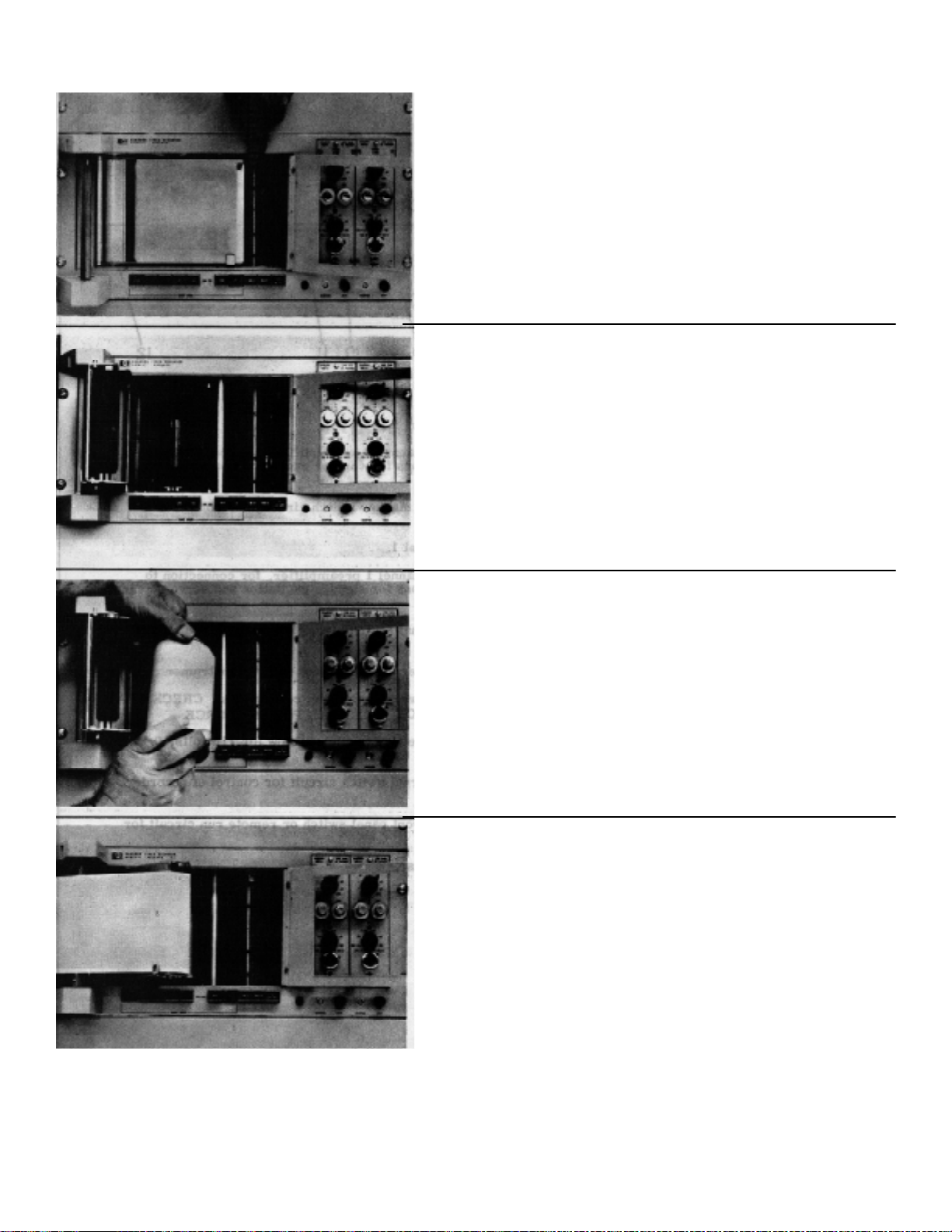
TM 11-6625-2751-14&P
RELEASE PAPER TABLE. Turn instrument OFF,
and open the recorder cover. Push the writing
table lock lever toward the galvanometers.
REMOVE SUPPLY SPOOL. Lift the paper table
outward and rest it on the takeup spindle. Lift the
supply spool out of the support brackets. Pull the
end discs apart to remove the paper core.
Figure 3-4. Permapaper Loading Procedures
3-4
Page 25
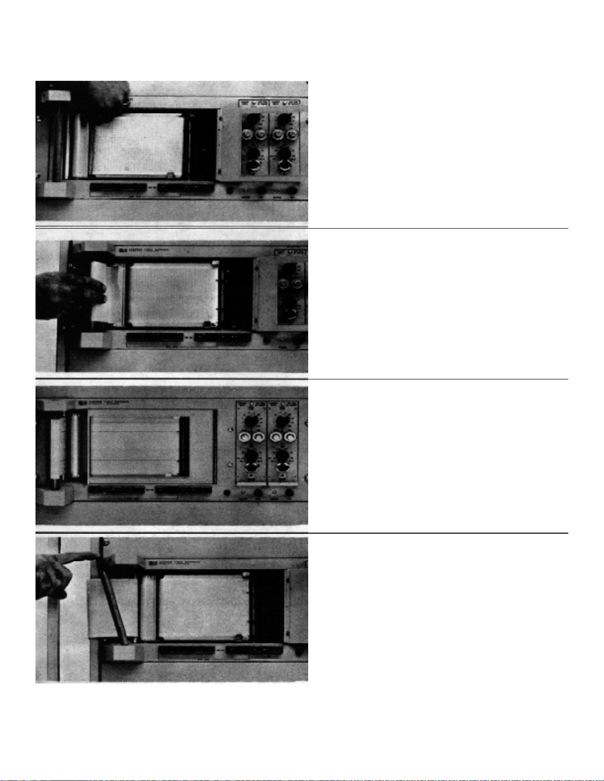
TM 11-6625-2751-14&P
FEED PAPER RNTO DRIVE ROLL. Fold back and
crease the paper about 1 inch from the end of the roll.
Start chart drive at 5 mm /sec. Insert the paper into the
drive roll squarely, so that the entire leading edge of the
paper contacts the drive roll. Stop the r ec order when the
paper is drawn tightly over the paper table. Lock the
paper table.
THREAD PAPER ONTO THE T AKEUP SPINDLE. Turn
on chart drive at 5 mm /sec, and loop paper around the
spindle tightly. The paper will be drawn onto the rotating
spindle. Stop the recorder. (The paper takeup f eature
must be used for satisfactory recorder operation.)
RECORDER IS READY FOR USE. Close the recorder
cover. A printed star appears on lower edge of chart, 30
feet from end of roll, to indicate remaining footage.
TO REMOVE PAPER AFTER RECORDING. Remove
the paper takeup spindle. Press the black plas tic button
on the end of the spindle. Pull out the upper and lower
ends of the spindle. After sliding the rec ording paper of f,
re-install the spindle, lower end first.
Figure 3-4. Permapaper Loading Procedures (Cont.)
3-5
Page 26
TM 11-6625-2751-14&P
1 Connect 7702A System to power line, and connect input signals to J1 and J2 on the rear recorder
panel. Rotate preamplifier attenuator or function switch to the OFF position. For 8801A, 8802A
preamplifiers, place signal use-off switch in OFF position.
2 Press POWER pushbutton. Indicator lamp on recorder will light. Allow three minutes warmup time.
3 Balance and calibrate pream plifiers following the procedures outlined in the pream plifier instruction
manual. When making calibration adjustments, set chart drive ON (see Step 4).
4 Press MM/SEC pushbutton, then press "5" pushbutton. Recorder will run at 5 mm /sec chart speed.
(When recording data, press numbered speed pushbutton to suit recording application. Select
mm/min speeds with recorder Options 11 or 12 by pressing MIN pushbutton.)
5 Adjust stylus heat for each channel to obtain a satisfactory trace intensity (when recording data which
is in the upper range of the recorder bandwidth, a higher stylus heat is required for good trace
definition).
6 Press STOP pushbutton to stop chart drive.
7 Press TIMER pushbutton to obtain one per second time markings on recording. For mm/min
speeds, optional timer records one mark per minute.
8 Press MARK pushbutton to record reference marks on lower edge of Permapaper.
Figure 3-5. System Operating Procedures
3-6
Page 27
TM 11-6625-2751-14&P
REMOTE CHART DRIVE CONTROL
1 Connect the switch circuit shown in Figure 2-8 to J13 on the rear panel of the recorder.
2 Place the LOCAL-REMOTE switch in the REMOTE position.
3 Press speed pushbuttons on the recor der front panel for the desired recor ding speed. W ith r emote
switch in RUN position, chart drive is ON. In STANDBY position, chart drive is OFF.
REMOTE MARKER CONTROL
4 Connect the switch circuit shown in Figure 2-9 to J15 on the r ecorder rear panel. Press the r emote
mark switch to record a reference mark on the lower edge of the Permapaper.
5 For systems with an auxiliary marker (Option 15), connect the switch circuit of Figure 2-9 to J14.
Press the auxiliary marker switch to record a reference mark between channels on the Permapaper.
Figure 3-6. Remote System Operation
3-7
Page 28
SECTION IV.
PRINCIPLES OF OPERATION
TM 11-6625-2751-14&P
4-1. INTRODUCTION.
4-2. This section of the manual contains the
principles of operation of the electrical and mechanical
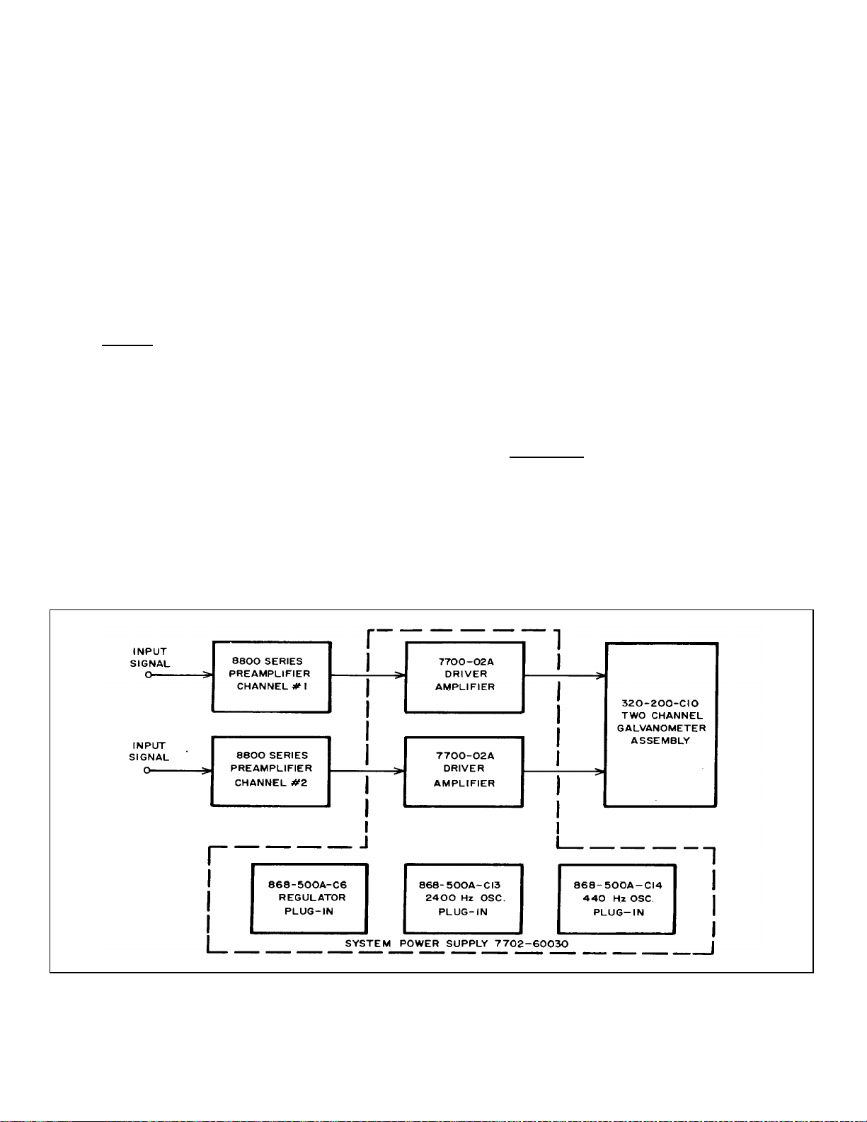
components in the 7702A System. A block diagram of
the system is shown in Figure 4-1. Introductory
paragraphs 4-3 to 4-13 contain basic information on
semiconductor diode and transistor circuits used in the
recording system.
4-3. BASIC CIRCUITS.
4-4. Diodes.
4-5. Semiconductor diodes are used in the signal
handling circuits and in the power supply rectifier and
regulator circuits.
4-6. Diodes are used as lim iters or clipper s in circ uits
to remove positive or negative peaks of wavefor m s. T he
diode can be used either as a waveform shaping circuit
or as a protective device to pr event excessive voltages
being applied to a sensitive circuit. Figure 4-2 (a) s hows
a limiter which prevents the negative peak of a pulse
from going more negative than approxim ately 0.6 volts.
Note that for a conducting silicon diode, the cathode
voltage is about 0.6 to 0.8 volts more negative than the
anode.
4-7. A diode clamper or dc restorer is a c ircuit which
establishes either the positive or negative peak of a
waveform at a particular dc refer ence voltage to provide
a definite baseline voltage for the waveform . Figure 4-2
(b) shows a clamper which provides a baseline of about
+20 volts for a negative pulse.
4-8. A diode regulator circuit uses either the constant
reverse-bias breakdown voltage characteristics of a
zener diode, or the constant forward bias voltage drop
characteristic of a s ilicon diode. Power supply reference
voltages are generally provided by break-down diodes
which maintains a constant voltage when supplied with a
reverse-bias voltage greater than their specified
breakdown voltage. Regulated voltages can also be
provided by a forward-biased silicon diode which
maintains a constant 0.6 to 0.8 volt drop. Figure 4-2 (c)
shows connections for both types of diodes.
4-9. Transistors.
4-10. Transistors are used throughout the 7702A in
amplifier and oscillator circuit configurations. Vacuum
tubes and transistors are functionally similar. In the tube,
a small grid-to-ca thode potential controls a large plate to
cathode current flow. In a transistor, a small base-toemitter current controls a large collector-to-emitter
current. A comparison of basic
Figure 4-1. Model 7702A System Block Diagram
4-1
Page 29
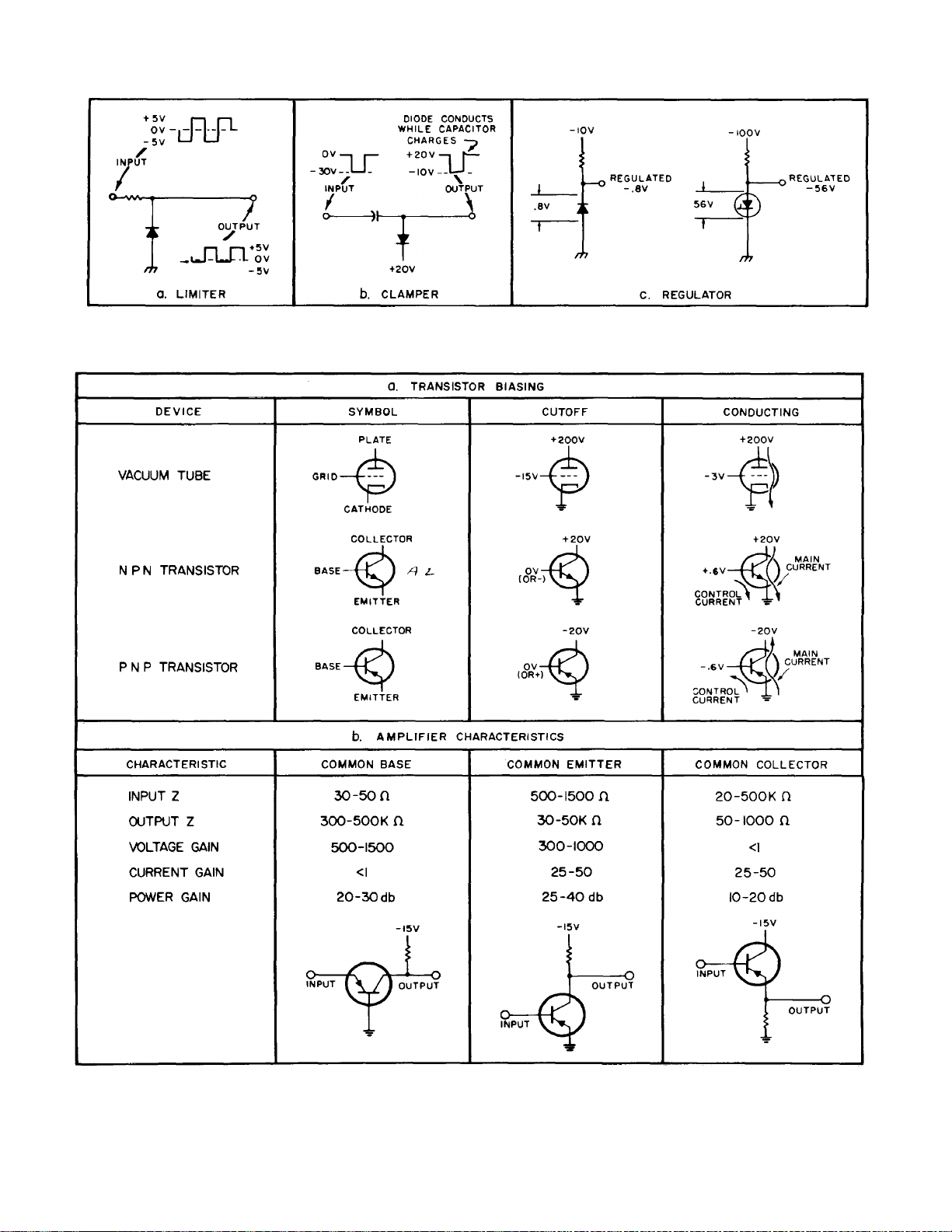
Figure 4-2. Basic Diode Circuits
TM 11-6625-2751-14&P
Figure 4-3. Transistor Operation
4-2
Page 30

TM 11-6625-2751-14&P
vacuum tube, NPN transistor, and PNP transistor
operation is shown in Figure 4-3 (a); indicated current
represents conventional flow of positive charges external
to the transistor and is not intended to indicate flow of
carriers inside the transistor structure. Notice that the
effect of emitter-base-collector voltages is totally
reversed between NPN and PNP transistors; circuits
which are arranged for an NPN transistor usually function
normally for a PNP transistor if supply voltages are
reversed.
4-11. There are three basic am plifier types, Figure 4-3
(b). These am plifiers are used alone or in com binations
to form complex circuits.
4-12. COMPONENT CIRCUIT DESCRIPTION.
4-13. Preamplifiers.
4-14. The principles of operation for the 8800 Series
Preamplifiers ar e contained in the particular preamplifier
Operating and Service Manual. A list of the preamplifiers
is shown in Section I, Table 1-3. The pream plifier s ignal
input connectors (J1, J2) mounted on the rear of the
recorder include provision f or us e of a guar d s hield in the
signal input cable. Use of a guard shield contributes to a
high common-mode rejection ratio when floating input
preamplifiers such as the 8803A are installed in the
system. Additional information on the preamplif ier guard
shield circuit is contained in the preamplifier manual.
4-15. The output signal of each preamplifier is
connected to the input of a 7700-02A galvanometer
driver amplifier. T he preamplif ier output signals are als o
available at connectors J21 and J22 at the rear of the
recorder, for connection to oscilloscopes or other
monitoring instruments . Signal distribution in the 7702A
System is shown in Figure 4-4.
4-16. Driver Amplifiers.
4-17. Two 7700-02A Galvanometer Driver Amplifiers
are mounted on the rear panel of the power supply 7702-
60030. The driver amplifier block diagram is shown in
Figure 4-5.
4-18. The input signal and the galvanometer feed-back
signal shown in the block diagram are amplified by the
balanced amplifier Q1, Q2, and directly coupled to the
differential amplifier Q3, Q4. The signal driving Q1 is
limited in amplitude by the transistors Q8 and Q9 to a
value which will not overload the driver amplifier or drive
the galvanometer writing arm excessively. The singleended output from the Q3, Q4 stage is obtained from the
collector of Q4 and is fed to the base of Q5. T ransistor
Q5 operates as a Class A driver f or the complem entarysymmetry Class B emitter-follower power amplifier Q6,
Q7.
The amplifier output is connected to the galvanometer
drive coil. A galvanometer feedback signal is obtained
from the galvanometer drive coil and velocity coil, and
returned as an input to the balanced amplifier.
4-19. FEEDBACK CIRCUIT. The feedback circuit
provides an adjustable amount of galvanometer damping
and galvanometer frequency compensation to obtain
optimum galvanometer transient response and frequency
response characteristics. Galvanometer damping is
obtained by generating a feedback voltage proportional
to the galvanometer coil velocity, and inserting this
voltage into the driver amplifier circuit with a polarity as to
reduce the coil velocity. Frequency compensation is
achieved by an RC network in the feedback c irc uit, which
determines the amplitude of high frequency feedback
voltages returned to the balanced amplifier.
4-20. The feedback voltage is derived from two
sources; the galvanometer velocity coil output, and the
voltage drop across R24 (see Figure 4-6). The velocity
voltage component is proportional to galvanometer coil
velocity, to damp the galvanometer motion. The
DAMPING control selects the amount of this velocity
voltage component which gives the best damping
characteristics. The drive coil current through R24
produces a voltage at the base of Q2 with an amplitude
approximately equal to the Q1 input signal due to the
high ratio of open loop to closed loop gain. This
feedback action forces a current through the
galvanometer drive coil alm os t ex ac tly proportional to the
input voltage.
4-21. The DAMPING control is adjusted for the best
transient response, and the COMPENSATIO N control is
adjusted to match the high-frequency roll-off of the
galvanometer. Figure 4-7 shows the galvanometer
response both in the frequency and time domains to
illustrate different degrees of damping.
4-22. The underdamped condition in Figure 4-7 (a)
depicts a partially damped system, with the damping
supplied only by the shorted coil frame of the galvanmeter. This shorted frame is equivalent to a low
resistence, one-turn short-circuited coil winding. The
currents induced in this coil frame develop a damping
force which is proportional to the coil velocity, and is in a
direction as to reduce the velocity. In this case, the
galvanometer oscillates around its final value before
coming to rest. The overdamped condition is the result
of excessive feedback damping voltage. In this case,
the galvanometer approaches its final value slowly,
giving too slow a rise time for recording short-period
transient voltages.
4-23. The ideal waveshape is the result of properly
adjusting the feedback voltage. In this case, the
galvanometer approaches the final value quickly, and
settles to the final value with a slight overshoot (about
4%). This corresponds to 71% of c ritic al damping, which
provides the desired transient and frequency response.
4-3
Page 31

TM 11-6625-2751-14&P
Figure 4-4. Signal Distribution Diagram
Figure 4-5. Model 7700-02A Driver Amplifier Block Diagram
4-4
Page 32

TM 11-6625-2751-14&P
(a) Transient response, step function input
Figure 4-6. Feedback Circuit-Simplified Schematic
4-24. The frequency response obtained with an underdamped, overdamped and 71% damped galvanometer is
shown in Figure 4-7 (b).
4-25. The frequency response for the 7702A
Recording System with an 8802A Preamplifier installed is
shown in Figure 4-8. The DAMPING c ontrol is adjusted
for 0.71 critical damping at 10mm deflection.
4-26. System Power Supply.
4-27. The 7702A System Power Supply (07706-
60030) furnishes operating power for the preamplifiers,
driver amplifiers, and the recorder chart drive circuits.
The power supply consists of the following sections:
a. ± 18 Vdc unregulated supply.
b. ± 12 Vdc regulated supply.
c. 440 Hz oscillator (provides chopper exc itation for
8803A Preamplifier).
d. 2400 Hz oscillator (provides transducer
excitation voltage for 8805A Carrier Preamplifier).
e. Control circuits for the chart drive motor, the
marker and timer assemblies, and the stylus heat circuit.
(b) Frequency response, sine-wave input
Figure 4-7. Galvanometer Frequency Response and
Transient Response
4-28. UNREGULATED DC SUPPLY. The
unregulated ± 18 Vdc supply (see Figure 4-9) consists of
transformer T1, diodes CR1 to CR8, and the filter
capacitors C13 to C16. Each pair of diodes (CR1, CR2,
CR3, CR4) connected across the T1 secondar y winding
forms a full wave rectifier circuit. The output of the
rectifiers is filtered by capacitors C13 to C16. The
distribution of the ± 18 volt power in the 7702A System is
shown in Figure 4-10.
4-29. REGULATED DC SUPPLY. The regulated ± 12
Vdc supply block diagram is shown in Figure 4-11, and in
the schematic diagram at the rear of the manual. The
+18 volt and -18 volt unregulated supply outputs are
connected to the series regulator transis tors Q1 and Q2,
which are controlled by the output of amplifiers Q3 and
Q6 in the 868-500A-C6 regulator card. Both regulated
voltages are controlled by one
4-5
Page 33

TM 11-6625-2751-14&P
voltage adjust control, R4. One input of differential
amplifier Q4, Q5 is maintained at 6.2 volts by zener
diode CR14; the other input is maintained at a fraction of
the -12 volt regulated output by the setting of R4. If the 12 volt regulated output voltage should vary slightly, this
will appear as a change in input signal levels between
the inputs to Q4 and Q5. This change is further
amplified by Q3, and applied to the series control
transistor Q1, with such polarity as to return the -12 volt
regulated output towards its original value. The +12 volt
regulated line is controlled in the sam e manner. In this
case, one input of the differential amplif ier Q7, Q8 is at
ground potential, and the other input is held at a value
determined by the voltage divider R12, R13. Assum ing
regulation of the -12 volt line, if the +12 volt output should
vary slightly, this will appear as a change in input signal
levels at the input to Q7, Q8. This change is further
amplified by Q6, and applied to the series control
transistor Q2 with such polarity as to return the -12 volt
regulated power in the 7702A System is shown in Figur e
4-12.
4-30. 440 HZ OSCILLATOR CARD. The 440Hz
Oscillator (868-500A-C14) is shown in the block diagram,
Figure 4-13. The frequency of the Q12, Q13 Os c illator is
determined by the transformer T4 and capacitor C15.
Output from T4 drives the power amplifier Q4, Q5.
Diodes CR21, CR22 control the
amplitude of oscillation at a level determined by zener
diode CR23. The power for the oscillator and power
amplifier is provided by the -18 volt unregulated supply
through regulator Q3. The base of Q3 is held at -12 volts
by the -12 V regulated supply.
Figure 4-8. 7702A System Frequency Response
Figure 4-9. Unregulated ± 18V Supply
4-6
Page 34

TM 11-6625-2751-14&P
Figure 4-10. Unregulated ± 18 V Power Distribution
Figure 4-11. Regulated ± 12 V Supply
4-7
Page 35

TM 11-6625-2751-14&P
Figure 4-12. Regulated ± 12 V Power Distribution
Figure 4-13. 440 Hz Plug-In Oscillator Block Diagram With Associated Circuits
4-8
Page 36

TM 11-6625-2751-14&P
4-31. 2400 HZ OSCILLATOR CARD. The 2400 Hz
Oscillator Plug-In Card (868-500A- C13) is shown in the
block diagram, Figure 4- 14. Q20 and Q21 oscillate at a
frequency determined by transformer T 7 and capacitors
C18 and C19 in parallel. Thermistors TM7 and TM8
provide oscillator stability. Diodes CR25, CR26 control
the amplitude of oscillation at a level determined by
zener diode CR24. Output from T7 is a 2400 Hz sine
wave balanced with respect to ground, which is used as
a transducer excitation voltage, and also provides a
reference voltage for the 8805A Carrier Preamplifier.
4-32. Oscillator power is provided by the -18 volt
unregulated supply through regulator Q19, located on the
plug-in card. The base of Q19 is held at a fixed voltage
by the regulated -12 volt supply. The Q19 emitter output
voltage (approximately 12 volts), supplies the Q20 and
Q21 oscillator circuit.
4-33. RECORDER DESCRIPTION.
4-34. Recorder consists of chart drive components to
transport the recording paper past the rec ording styluses
onto a paper takeup assembly, and a dual galvanometer
assembly. Also included are control circuits for the
following functions: chart drive, stylus heat, timer and
marker stylus.
4-35. Chart Drive Components.
4-36. The chart drive mechanism consists of: (1) a 450
rpm (60 Hz) synchronous drive motor, coupled to speed
reduction gears to obtain chart speeds f rom 1 m m /sec to
100 mm/sec; ( 2) pushbutton actuated c lutch assem blies,
located on the reduction gear shafts, to determ ine which
of the speed reduction gears are in the drive tr ain for the
chart speed selected; (3) a paper drive assembly, which
includes a paper supply spool, a brake roll to hold the
paper under tension as it passes over the paper table
and a paper drive roll driven by the output of the speed
reduction gears, and; (4) a paper takeup assembly,
which stores the chart paper following the recording
process.
4-37. Drive Motor and Speed Reduction Gears.
4-38. The drive motor (B1) is coupled to the input
shaft, see Figure 4-15(a), by means of a drive c hain and
sprockets. The input shaft rotates at 300 rpm for the 1 to
100 mm/sec chart speeds (50 or 60 Hz power line). Four
additional chart speeds are available (Option 11 or
Option 12) with the addition of a second synchronous
drive motor. The optional mm/min drive motor (B103)
rotates the input shaft at 5 rpm (50 or 60 Hz power line),
through a similar sprocket and chain coupling. An
overrunning clutch is installed on each drive motor
sprocket so that only one motor shaft rotates at a time.
Figure 4-14. 2400 Hz Plug-In Oscillator Block Diagram
4-9
Page 37

TM 11-6625-2751-14&P
Figure 4-15. Chart Drive Motor and Speed Reduction Gears
4-10
Page 38

TM 11-6625-2751-14&P
4-39. Two speed-reduction gear assemblies are
included in the recorder. The first speed reduction
assembly, Figure 4-15(b), contains a 5:1 speed reduction
gears. The second speed reduction, Figure 4-15 (c),
contains both 5:1 and 4:1 reduction gears, to obtain a
20:1 overall speed reduction for the second assembly.
4-40. Pushbutton Actuated Clutch Assemblies.
4-41. A spring clutch installed in each of the speed
reduction assemblies permits the reduction gears to be
by-passed, resulting in a 1:1 speed ratio. The spring
clutches are mechanically linked to the four-speed
pushbuttons on the front panel of the recorder by the
clutch actuator assembly shown in Figure 4-12 of
Section VI. Pressing one of the pushbuttons c auses the
appropriate clutch to be engaged for the speed selec ted.
Table 4-1 lists the speed reductions in effect for 1
mm/sec to 100 mm/sec recorder operation.
Table 4-1. Speed Reduction Ratios
DRIVE SPEED
SPEED REDUCTION
MM/SEC 1 ST 2 ND
CHART
DRIVE
MOTOR
1 5:1 20:1
5 1:1 20:1
20 5:1 1:1
100 1:1 1:1
CHART
DRIVE
ROLL
4-42. The power flow through the first speed reduction
assembly is shown in Figure 4-16. For 1:1 speed r atio,
the pushbutton linkage pulls the clutch actuator arm ( 1)
away from the clutch housing. This action locks the gear
(2) to shaft (3). The resulting power flow by-passes the
5:1 speed reduction gears (4) (5), on the upper end of
the two shafts. An overriding clutch, mounted in the gear
hub (5) disengages gear (5) from shaft (6). For 5:1
speed transfer, the push-button linkage causes the
clutch actuator arm to engage with the clutch housing,
preventing the housing from rotating. This action
releases gear (2), permitting it to rotate freely on shaft
(3). The power flow is from shaft (3) through the
reduction gears (4), (5), to shaft (6). Gear (7) then drives
the output gear (2).
4-43. The second speed reduction ass embly, which is
driven by gear (2), operates in a similar manner. For
medical operating speeds, 2.5 to 50 mm/sec, the
reduction ratios in the first and second speed reduction
assemblies are 2:1 and 10:1.
4-44. Chart Drive Circuits.
4-45. The chart drive circuits are shown in the
functional diagram, Figure 4-17. The diagram shows the
recorder with the mm/sec drive motor (B1) and the
optional mm/min drive motor (B103).
4-46. The recorder may be connected to either a 115
or 230 volt power line. The switch S2 on the rear of the
recorder is set to agree with the line voltage. For 115
volt input, the power line is connected directly to the chart
drive circuits from transformer
Figure 4-16. First Speed Reduction Assembly Operation
4-11
Page 39

TM 11-6625-2751-14&P
T1 terminals 1 and 2. For 230 volt line power, the line
voltage is applied to terminals 1A and 2 of transform er
T1. Through transf ormer action, the voltage is reduced
to 115 volts at terminals 1 and 2 of T1. Ter m inal 2 of T 1
is connected to the upper lead of the mm/sec drive
motor. With the mm/min drive motor installed in the
recorder, terminal 2 is also connected to the mm/min
drive motor. The lower ter minal of the drive motor(s ) is
connected to switch S1C. For recorders with mm/sec
speeds only, the S1C switch is always in the mm/sec
position. For recorders with the mm/min drive motor
installed, the switch may be operated to select either the
mm/sec or the mm/min drive motor. The chart drive
circuit continues to the left of S1C and upward to the
STOP switch S1D. When any of the numbered speed
pushbuttons is pressed, the STO P switch is closed and
drive motor power is applied. Pressing the STOP
pushbutton opens the chart drive circuit. With the
LOCAL/REMOTE switch in the REMOTE position, the
switch circuit shown is connected to the connector J13
for remote control of the chart drive start-stop function.
4-47. Stylus Heat Circuits.
4-48. The stylus heat circuits are shown in the
functional diagram, Figure 4-18. Each recording stylus
has a hot wire element which is heated by the ac line
voltage (50 or 60 Hz). The line voltage is reduced by the
transformers T1, T2, to the level required for the
operation of the stylus heat elements.
The temperature of the heated element in each
recording stylus is adjustable for setting desired trace
intensity. This adjustment is m ade by means of variable
resistors R2, R3, which are front panel contr ols marked
HEAT. The recorder als o contains a circ uit to s witch the
level of stylus heat for each of the selected mm/sec
operating speeds. Thus the same trace intensity is
obtained for each of the mm/ sec speeds without the
need for manual readjustm ent when a different speed is
selected. The mm /min speeds do not require a diff erent
level of heat for each of the four speeds, so a constant
voltage is applied to the stylus circuit for all speeds
selected.
4-49. STYLUS HEAT CIRCUITS-CHART DRIVE OFF.
When the line POWER switch S1A is closed, the 115
volts ac line power is present at T1 terminals 1 and 2.
Through transform er action, 115 volts is also pr esent at
terminals 1 and 1A. For 230 volt power line oper ation,
the S2 switch is in the 230 volt position. The line voltage
applied to terminals 1A and 2 is stepped down by
transformer action so that 115 volts is present at T1
terminals 1 and 1A. W ith the REMOT E/LOC AL switch in
the LOCAL position, and the STOP pushbutton press ed,
115 volts is applied to terminals A and E of the T2
primary windings. The T2 secondary voltage (0.75 V) is
connected to each stylus, providing a standby heat level.
4-50. STYLUS HEAT CIRCUIT: CHART DRIVE ON.
With the power line switch ON and the 1 mm /sec speed
pushbutton pressed, the RUN-STOP switch is
Figure 4-17. Chart Drive Circuit
4-12
Page 40

TM 11-6625-2751-14&P
in the RUN position, and the switch contact adjacent to
T2 terminal E is closed. The circuit is completed from
terminal E of T2 to the power line input through the 1
mm/sec speed switch; through S1C, S1D, S3, and
terminal 1 of T1. For higher speeds, transformer T2
turns ratio tap is changed, resulting in progressively
higher stylus heat voltages. A table of T2 output
voltages for the various chart speeds is shown in Figure
4-18.
4-51. Marker and Timer Circuit.
4-52. The recorder m ark er and tim er circuitr y is shown
in the functional diagram, Figure 4-19. The following
description includes the circuitry for the s tandard 7702A,
and for the optional marker and timer features.
4-53. MARKER CIRCUIT. The 7702A Recorder
includes a marker assembly for recording a reference
mark on the lower edge of the chart. The marker
assembly consists of an ac operated marker coil which
vibrates a heated stylus attached to the coil armature.
The lower end of the marker coil is connected to
transformer T 1, terminal 3 (15 Vac). The upper end of
the coil is connected to the MARK switch S1E. Press ing
the MARK button grounds the upper end of the marker
coil, completing the circuit to the grounded T1 c enter tap
(terminal 4). The mark er is also ac tuated from a r emote
location by connecting a switch circuit to J15.
4-54. AUXILIARY MARKER CIRCUIT. An additional
marker, which rec ords on the chart between channels 1
and 2, is available as Option 15. The auxiliary marker is
actuated by a switch circuit connected to J14.
Figure 4-18. Stylus Heat Control Circuit
4-13
Page 41

TM 11-6625-2751-14&P
Figure 4-19. Marker and Timer Control Circuitry
4-14
Page 42

TM 11-6625-2751-14&P
4-55. TIMER CIRCUIT. The standard 4-speed
recorder, for 60 Hz power line, includes a 14002S Timer
Assembly. This timer is actuated by the front panel
TIMER pushbutton switch, to record one timing mar k per
second on the chart. The timer as sem bly consists of a 1
RPS synchronous timing motor and a magnetic reed
switch. The reed switch is wired so that the marker coil
is energized each time the switch closes, recording a
timing mark on the lower edge of the chart once per
second. Plug-in Timer Assembly 14002T is supplied
with recorders operation on 50 Hz line power. A second,
optional timer can be plugged into J17 on the rear of the
recorder to provide minute timing marks for recorders
equipped with eight recording speeds. Table 4-2 lists the
timing assemblies for use with the 7702A System.
Table 4-2. Timer Assembly Part Numbers
I/SEC. TIMER I/MIN. TIMER
7702A 14002S 14002V (OPT 14)
(60 Hz PWR)
7702A OPT 08 14002T 14002R (OPT 13)
(50 Hz PWR)
4-56. Pressing the power pushbutton closes the line
power switch S1A (see Figure 4-19). For 115 volt
operation, the S2 switch is in the lower position, and the
line power is applied to T1 terminals 1 and 2. Through
transformer action, 115 volts is also present on T1
terminals 1 and 1A, to operate the tim er circuit. For 230
volt line operation, T1 steps the line voltage down to 115
volts. Terminal 4 of the mm/sec timer motor B101 is
connected to T1 terminal 1A. With the TIMER and
mm/sec pushbuttons pressed, T1 terminal 1 is
connected to terminal 3 of the mm/sec timer motor
through S3, the TIMER switch S1B terminals 7 and 8,
and the S1C switch.
4-57. For each one per second closure of the timer
switch, current flows from T1 terminal 3 through the
marker coil, terminals 1 and 2 of the timer, S1C contacts,
the S1B terminals 5 and 6, to ground. Each time the
marker coil is energized, the marker stylus records a
time mark on the chart.
4-15
Page 43

SECTION V.
MAINTENANCE
TM 11-6625-2751-14&P
5-1. INTRODUCTION.
5-2. This section provides the maintenance and
service information for the 2-Channel 7702A Recording
System. Maintenance information includes perform ance
checks (Paragraph 5-5) which can be used as incoming
quality control checks or as a performance check after
repair; preventive maintenance (Paragraph 5-10);
corrective maintenance (Paragraph 5-48);
troubleshooting and repair (Paragraph 5-85).
5-3. TEST EQUIPMENT.
5-4. Recommended test equipment for performance
checking, troubleshooting, repair, and for making
adjustments is listed in Table 5-1 together with the
performance characteristics required. Other test
equipment can be used if their specifications equal or
exceed those listed. Refer to the Maintenance Alloc ation
Chart in the appendix for the required test equipment.
5-5. PERFORMANCE CHECKS.
5-6. General.
tions and to provide a permanent record of the
performance of the system . These checks verify proper
operation of all circuits in the system and can be used:
a. As part of an incoming inspec tion check of
the component specifications.
b. Periodically, where maximum reliability is
paramount.
c. As part of a troubleshooting process to
locate malfunctioning circuits.
d. After any repairs or adjustments, before
returning the system (or components) to regular service.
5-8. VARIABLE LINE VOLTAGE.
5-9. During the following procedures, the system (or
component) should be connected to the power source
through a variable voltage device so that line voltage can
be varied ±10% from nominal (115 or 230 Vac ) to as sur e
proper operation of the system under various supply
conditions.
CAUTION
5-7. The Performance Checks (Table 5-2) and
Performance T est Card (to be filled out during incom ing
inspection) are designed to verify specifica-
Table 5-1. Recommended Test Equipment.
INSTRUMENT TYPE REQUIRED CHARACTERISTICS USE INSTRUMENT
Variable Voltage 115 or 230 volt; 0-130 Vac 2 amp General Test General Radio
Controller 0-260 Vac 1 amp Variac
DC VTVM 1 mV to 1000V full-scale Performance Test HP 412A
1 mA to 1 amp and Troubleshooting
Oscilloscope dc to 450 kHz Performance Test HP 120B
10 mV/cm to 10V/cm and Troubleshooting
Power Supply Stable to within 1/10% Signal Source Harrison Lab
output greater than 1.5 volts 808A
Voltage Divider Accurate to 0.05% Performance General Radio
less than 1.5 K ohms Checks
Differential VTVM ±10V with 5-digit resolution Monitor HP 740A, 741A
AVOID DAMAGE BY REMOVING
POWER FROM THE SYSTEM PRIOR
TO REMOVAL OR REPLACEMENT OF
ASSEMBLIES OR COMPONENTS.
RECOMMENDED
5-1
Page 44

TM 11-6625-2751-14&P
Table 5-1. Recommended Test Equipment (Cont.)
INSTRUMENT TYPE REQUIRED CHARACTERISTICS USE INSTRUMENT
RECOMMENDED
Function Generator Sine Square Oscillator to 150 Hz Signal Source HP 202A
AC/DC VTVM 300 volts full-scale Performance HP 410B
Testing
Wattmeter 200 watts 50/60 Hz Adjustment Any
Stylus Pressure 0-5 grams Adjustment Sanborn 14015A
Tester
Frequency Counter To 40 kHz Performance HP 5223L
Checks
Table 5-2. Performance Checks
POWER SUPPLY (07702-60030)
1. ± 12 VOLT REGULATED SUPPLY
Regulation: With ± 10% change in line voltage, change in output voltage is 1% maximum (0.12 volt dc).
a. Install two 8800 Series Preamplifiers in the 7702A System using a Variac or a similar variable voltage
source to supply line power to the system. For 115 V ± 10% power line, adjust the Variac output to 115 volts.
For 230V ±10% power line, adjust the Variac to 230 volts output. See Reference 8, Figure 3-3, Section III.
b. Connect a dc VTVM to the -12V dc test point, which is pin 1 on the upper drive amplifier circuit board
07700-62010. Voltage should be -12 Vdc ± 20 mV. Adjust R4 on the Regulator 868-500A-C6 if necessary.
c. Incr ease the Variac output voltage 10% from the 115 V or 230V level. VTVM reading should c hange no
more than 0.12 volts from reading in step b.
d. Decrease the Variac output voltage 10% from the 115 V or 230 V level. The VTVM reading should change
no more than 0.12 volts from the reading in step b.
e. Connect the VTVM to the +12 volt test point which is pin 3 on the upper driver amplifier circuit board 07700-
62010. For a line voltage of 115V or 230 V, the test point should read approximately +12 volts.
f. Adjust the Variac output ± 10% as described in steps c and d. T he VTVM reading should not vary more
than ± 0.12 volts from the reading in step e.
Ripple: With 115 or 230 volt line power, ripple on +12V or -12V supply should not exceed 10 mV pp.
Connect a test oscilloscope to the +12 and -12 test points described above. The measured ripple should not
exceed 10 mV pp, for a 115V or 230V line voltage.
2. ± 18 VOLT UNREGULATED SUPPLY
Connect the dc VTVM to the following test points, to determ ine whether the +18V and -18V ±2V supply voltages
are present.
+18 V - Pin 7 on the upper driver amplifier circuit board 07700-62010.
-18V - Pin 8 on the upper driver amplifier circuit board 07700-62010.
5-2
Page 45

Table 5-2. Performance Checks (Cont.)
3. 2400 Hz OSCILLATOR 868-500A-C13
Output voltage and frequency: 14 volts pp each side to ground; frequency between 2.352 kHz and 2.448 kHz.
a. Connect a test oscilloscope to J11l pin 4 and pin 1 (com mon). The am plitude of the output should be at
least 28 V pp.
b. Disconnect the oscilloscope and connect a frequency counter to the same test points. The frequency
should read between 2.352 kHz and 2.448 kHz.
4. 440 Hz OSCILLATOR 868-500A-C14
a. Connect test oscilloscope to J11 pin 11 and pin 9 (c ommon). The amplitude of the output should be at
least 14 V pp.
b. Disconnect the test oscilloscope and connect the frequency counter to the same test points. The
frequency should read between 430 and 450 Hz.
RECORDER
1. STYLUS: MECHANICAL CENTER
a. Check the stylus pressure. Correct stylus pressure is 2 to 2-3/4 grams.
b. Set the recorder POW ER switch to OFF. The stylus on each galvanometer s hould come to rest at chart
center, ± 1 division.
TM 11-6625-2751-14&P
2. LINEARITY
With 8801A, 8802A: 0.25 div. 8803A: 0.25 div (1 m V range 0.35 div). 8805A, 8806B, 8809A: 0.4 div (after
setting mechanical zero of stylus within ± 1 div of chart center and calibrating for zero error at center scale and
+20 divisions). 8807A: 0.55 div +0.05 div x scale expans ion, 330 Hz to 5 k Hz (after setting m echanical zero of
stylus within ± 1 division of chart center and calibrating for zero error at lower and upper ends of printed
coordinates). 8808A: 50 dB span 1.25 div, 100 dB span 1 div (after setting m echanical zero of stylus within ± 1
division of chart center and calibrating for zero error at lower and upper ends of printed coordinates).
a. Connect a precision voltage divider to the signal input connector J1 (Channel 1) or J2 (Channel 2).
b. Connect a signal source to the voltage divider input. (A dc source is us ed for the 8801A, 8802A, 8803A,
8809A Preamplifiers.)
c. Balance and calibrate the preamplifier using the procedure outlined in the preamplifier instruction manual.
d. Set the preamplifier range switch to O FF. Adj ust the pr eamplifier POSIT IO N c ontrol to c enter the s tylus on
the recording chart.
e. Set the preamplifier RANGE and GAIN controls to obtain a 20 division stylus deflection; this is the 100%
value.
f. Set the voltage divider output in steps of 25% voltage, starting with 125%, and observe the recording:
g. The stylus deflection for each signal level should be within the limit specified above for each preamp.
125% = 25 div deflection
100% = 20 div deflection
75% = 15 div deflection
50% = 10 div deflection
25% = 5 div deflection
5-3
Page 46

3. FREQUENCY RESPONSE
Preamps Dc to less than 3 dB down at
8801A 125 Hz
8802A 125 Hz
8803A 86 Hz
8805A 104 Hz
8806B With 60 Hz fixed frequency plug-in 12 Hz;
8807A 54 Hz Option 01, 9 Hz
8808A Not Applicable
8809A 125 Hz
The system frequency response and transient r esponse using the dc preamplif iers 8801A, 8802A, 8803A, and
8809A are checked using the following procedure. For other preamplifiers, see the preamplifier manual:
a. Connect the oscillator to the preamplifier input connectors J1 and J2.
b. Center each stylus using the preamplifier position controls.
TM 11-6625-2751-14&P
Table 5-2. Performance Checks (Cont.)
400 Hz fixed frequency plug-in 65 Hz;
5000 Hz fixed frequency plug-in 125 Hz
Frequency Response
c. Set the DAMPING controls for each channel full clockwise.
d. Record a 2-Hz sine wave at 10 divisions pp amplitude.
e. With the oscillator output voltage maintained at the same amplitude, set the oscillator to the frequency
listed above.
f. Adjust the com pens ation (C OMP) c ontro l located at the r ear of eac h dr iver amplifier (upper dr iver f or upper
channel) for a 7-div pp recorded signal (3 dB down).
Transient Response
g. Set the oscillator to 2 Hz, square wave output. Adjust oscillator amplitude to obtain a 25 division pp
recorder amplitude. (The calibration source within the preamp m ay be used in place of a square wave osc illator
to record a step function.)
h. Run recorder at 20 mm/sec or 25 m m/sec (medical speed) and adjust the DAMPING controls for each
channel to obtain a 1 division overshoot on the leading edge of the square wave.
Rise Time
i. Run recorder at 100 mm/sec or 50 m m/sec while recor ding above signal. Obs erve the recor ded rise tim e
which is the time required for the signal to rise from the zero amplitude level (-12.5 divisions) to the 90% level
(+10 divisions).
Preamplifier Rise Time (10 div, 10-90% with 4% overshoot)
8801A 5 msec
8802A 5 msec
8803A 7 msec
8805A 5.6 msec
8809A 5 msec
10 msec = 1 div at 100 mm/sec
10 msec = 1/2 div at 50 mm/sec
5-4
Page 47

4. DRIFT
Line voltage from 103 to 127 volts. Maximum allowable drift for each preamplifier is:
Preamplifier Drift
8801A, 8802A 0.2 div
8803A 0.27 div
8805A, 8806B 0.35 div
8807A 0.005 div x scale expansion + 0.30 div
8808A Not applicable
8809A 0.50 div
a. Apply 103 volts ac power line voltage to 7702A System.
b. Run the recorder at 5 MM/SEC and center the styli with the position controls.
c. Increase the power line voltage to 127 volts ac and observe each stylus trace deviation from the zero
reference point.
5. NOISE (with zero signal input)
Preamplifier Noise
8801A 0.2 div pp
8802A 0.2 div pp
8803A 1 div pp max. gain
8805A 0.2 div pp and 1% of chart deflection
8806B 7 µ V x square root of frequency response, referred to input
8807A Baseline offset and/or noise 2 mV rms referred
8808A 50 dB range: 0.8 div, pp
8809A 0.1 div, pp
TM 11-6625-2751-14&P
Table 5-2. Performance Checks (Cont.)
1 div pp min. gain
To input plus 0.025 div x scale expansion
100 dB range: 0.4 div, pp
(With bottom scale input signal)
Table 5-3. Recorder Minor Repairs and Adjustments
PARTS CHECKED DEFECTS NOTED REQUIRED REPAIRS
1. Stylus 1. Bent or twisted writing element. If the
writing element is not at a 90% angle to
the paper table platen with the stylus at
center chart position, non- linearity will
result (unequal upscale and downscale
deflections).
2. Broken stylus side wire support.
3. Broken writing element welds.
4. Broken connection between side wires
and mounting base.
5. Side wires twisted out of parallel with
each other.
6. Writing element nicked.
7. Carboned (blackened) writing element. 7. Clean with cleaning fluid.
8. Mounting base contact surface
corroded.
9. Stylus mounting adapter corroded. 9. Clean with fine sandpaper being careful
5-5
1. through 6. Defects - Replace stylus.
8. Clean gently with fine sandpaper taking
care not to remove contact plating.
not to remove plating on stylus adapter
contacts.
Page 48

Table 5-3. Recorder Minor Repairs and Adjustments (Cont.)
PARTS CHECKED DEFECTS NOTED REQUIRED REPAIRS
TM 11-6625-2751-14&P
2. Platen 1. Carbon buildup (caused by stylus heat
too high).
2. Slight nicks or burrs on knife edge. 2. Use fine emery stone to remove all
3. Deep dents, nicks, or burrs on knife
edge.
3. Table Plate 1. Carbon, dirt, or other contamination. 1. Clean with Chlorothene.
2. Dents, nicks, or burrs. 2. Remove sharp edges with fine emery
3. Burrs or nicks on radius at bottom of
table plate.
4. Pressure Roll 1. Seized oilite bearings. 1. Clean out with Chlorothene and oil
2. Slight burrs or nicks on working
surface.
5. Drive Roll Guide 1. Squeaking or chattering from roll guide
and table plate.
6. Drive Roll 1. Surface cracks or cuts. 1. Replace Drive Roll. If Permapaper
2. Drive Roll surface slick or dirty. 2. a) Remove Permapaper from
7. Brake Roll 1. Surface cracks. 1. Replace Brake Roll.
2. Surface dirty or slick. 2. Clean surface with Chlorothene. Turn
1. Clean with cleaning fluid such as
Chlorothene.
sharp edges.
3. Replace platen (pull platen from table).
stone. Do not cut Permapaper on table
plate.
3. Remove sharp edges with emery stone.
bearings sparingly.
2. Remove sharp edges with emery stone.
1. Check for clearance of roll guide edge
near Drive Roll. Adjustment can be
made by loosening mounting screws
and moving Drive Roll Guide away from
Drive Roll. See Ref. 20, Figure 11, IPB
Section.
CAUTION
Do not run recorder with loose drive roll
guide.
winds around Drive Roll, use a bluntedged instrument to cut the paper.
Recorder.
b) Swing the hinged paper guide
upward on the Drive Roll. See
Figure 5-1.
c) Clean surface of DriveRollwith a
cloth dampened with Chlorothene
with recorder running at highest
speed. Do not saturate Drive Roll
with Chlorothene and be careful that
the cleaning cloth does not get
caught in the Drive Roll. Do not
install Permapaper until Drive Roll is
completely dry.
Brake Roll by hand while cleaning.
5-6
Page 49

Table 5-3. Recorder Minor Repairs and Adjustments (Cont.)
PARTS CHECKED DEFECTS NOTED REQUIRED REPAIRS
TM 11-6625-2751-14&P
7. Brake Roll
(Continued)
3. Brake Roll sticking or jamming. 3. With proper brake adjustment, the
Brake Roll should turn smoothly even
though a small pressure is required to
turn the Brake Roll by hand. Three
defects which can cause Brake Roll
jamming are:
a) Side plate bearing dirty or too tight.
b) Brake disc washer not lubricated.
c) Brake Roll adjustment too tight.
For lubrication or replacement of Brak e Roll,
do the following:
Brake Roll Removal: Turn the brake roll
screw at the right end of the Brake Roll
counterclockwise until the Allen-head
setscrew is almos t f lus h with the c ollar . See
Figure 5-3. Push the spring-loaded screw
until the right end of the Brake Roll can be
pivoted upward. Pull the Brake Roll out of
the left table flange.
Brake Roll Lubrication:
a. Following the removal of the Brak e Roll
from the recorder , clean the brake disc
washer and left bearing with
Chlorothene. Replace bearing if
defective.
b. Re-oil the bearing and lubricate the
brake disc (cork washer) with a thin
layer of No. 39LU-7 grease.
c. Clean and re-oil the right brake roll
support bearing. Replace the bearing if
defective.
8. Paper Take-Up 1. Paper too loose or tight on spindle;
take-up operates erratically, particularly at low speeds; take-up
chatters.
5-7
Re-installation and Adjustment of Brake
Roll:
Fit the Brake Roll into the left table flange,
and push the spring-loaded screw on the
right end until the Brake Roll can slide into
the right table flange. Adjust for proper
paper tension on platen by turning the Brake
Roll screw clockwise until the paper is snug,
but not tight, on the platen.
1. Adjust the Paper Take- Up assembly as
outlined below. If problem is not
corrected, lubricate the Paper Take-Up
assembly. See Paragraph 5-38.
Page 50

Table 5-3. Recorder Minor Repairs and Adjustments (Cont.)
PARTS CHECKED DEFECTS NOTED REQUIRED REPAIRS
TM 11-6625-2751-14&P
8. Paper Take-Up
(Continued)
Paper Take-Up Adjustment:
a) Run recorder at 20 mm/sec or 25 mm/sec for preliminary check of paper tension
between drive roll and take-up spindle. Paper tension should be snug, not tight or
loose. Adjust take-up clutch screw cloc kwise, then counterc lockwise until s light finger
pressure depresses paper (see Figure 5-7).
b) Run recorder at highest speed and make clockwise and counterclockwise
adjustments until proper paper tension is achieved.
c) Repeat adjustments at slow speeds, then check operation at high, medium and slow
speeds for a check on overall operation of the Paper Take-Up.
Figure 5-1. Recorder Platen and Writing Edge
5-8
Page 51

TM 11-6625-2751-14&P
PERFORMANCE CHECK TEST CARD
Model 7702A Oscillographic Recording System Tests performed by __________________________
Serial No.____________________________ Date __________________________
Description Check
1. STYLUS MECHANICAL CENTER: CH 1
Each channel ± 1 division from chart center with
system power OFF.
2. POWER SUPPLY ± 12 VOLTS NEGATIVE -12 V, adjustable
ADJUSTABLE +12V, ±0.5V
3. POWER SUPPLY ± 18 VOLTS UNREGULATED. +18 V ± 2V
AMPLITUDE DEPENDS ON LINE VOLTAGE. -18V ±2V
4. LINEARITY:
8801A, 8802A: 0.25 div
8803A: 0.25 div (1 mV range 0.35 div) CH 1
8805A, 8806B, 8809A: 4 div
8807A: 0.55 div + 0.05 div x scale expansion CH 2
8808A: 50 dB span: 1.25 div
100 dB span: 1 div
5. FREQUENCY RESPONSE WITH DC PREAMPS:
dc to 3 dB down at CH 1
8801A 125 Hz
8802A 125 Hz CH 2
8803A 86 Hz
8809A 125 Hz
6. DRIFT: Line voltage from 103 to 127 V
CH 2
+12V ripple, O1mV pp
-12V ripple, 10mV pp
8801A, 8802A: 0.2 div CH 1
8803A: 0.27 div
8805A, 8806B: 0.35 div
8807A: 0.005 div, CH 2
x scale expansion +0.30 div
8808A: does not apply
8809A: 0.50 div
5-8 (a)
Page 52

7. NOISE: With zero signal input
8801A: 0.2 div pp
8802A: 0.2 div pp
8803A: 1 div pp max gain
1 div pp min gain
8805A: 0.2 div pp +1% of chart deflection
8806B: 7 µ V x square root of frequency
response, referred to input.
8807A: Baseline offset and/or noise
2 mV rms referred to input plus
0.025 div x scale expansion
8808A: 50 dB range: 0, 8 div pp
8809A: 0.1 div pp
TM 11-6625-2751-14&P
PERFORMANCE CHECK TEST CARD (Cont.)
CH 1
CH 2
5-8 (b)
Page 53

5-10. PREVENTIVE MAINTENANCE.
5-11. Preventive maintenance is recommended every
1000 hours of operation or every six months , depending
upon the operating conditions. Table 5-3 is
recommended as a check chart for preventive
maintenance as well as an aid for minor repairs and
adjustments.
5-12. Mechanical
TM 11-6625-2751-14&P
b. Paper Take-Up. Inspec t paper on take-up
spindle. If it is too loose or excessively tight, see Table
5-3.
c. Paper Tension. Inspect paper travel over
the writing edge at the highest MM/SEC speed. The
paper should remain tight against the edge during travel,
not curve over it. To adjust the brak e screw, see Table
5-3.
5-13. Refer to Initial System Check in Section II and
perform these checks before continuing.
5-14. Switch power to the system OFF. Inspect the
system for symptoms of mechanical or electrical
overload. Check for dents, rust, corrosion, or other
evidence of mechanical or electrical abuse. Check that
all system components ar e securely mounted, including
the cable connectors. Check the cables for strain,
breaks, frayed insulation.
5-15. The following steps will check the recorder
mechanical operation:
a. Paper Loading. Load Permapaper in the
recorder. Apply power and run two feet of paper at the
highest paper drive speed to correct any mistracking
resulting from paper loading. Appr oximately 3/32 in. of
the platen table surface should be visible to the right of
the chart. Check that paper take-up is working properly.
d. Paper Tracking. Run approxim ately 5 feet
of chart at the 50 mm or 100 mm speed with one
channel stylus centered. Remove the recording and
measure the peak-to-peak varaition of the trace due to
paper drift. The tracing should not vary more than 0.5
mm from center. If paper weave exceeds the limit,
check paper loading techniques and paper tension.
Check Table 5-3.
e. Paper Parallax. Check parallax with paper
drive motor OFF and Permapaper tight against the
writing edge. With the side of a pencil, mar k the outer
edges of the two channels on the recording paper
precisely where the paper is angled over the knife edge
of the platen. The two points marked on the recorder
must lie within 0.25 division of each other on the timing
lines. If not, check paper loading technique and brake
roll tension.
f. Writing Stylus. Remove each stylus by
loosening clamping screw and disconnecting the stylus
heat wires (see Figure 5-2); lift stylus from
Figure 5-2. Stylus Adjustment Screws and Limits
5-9
Page 54

holder. Inspect the writing surface. It should be clean
and straight. If the stylus is bent, it som etimes can be
straightened with tweezers; if not, replace it. If the stylus
is burred or twisted, replace it. Insert a good stylus in
galvanometer clamp and secure in place. The flexible
stylus heater leads should not touch the adjacent side
panel. Tighten the stylus heat lead screws. The ribbon
must be at 90° to the writing edge to obtain the correct
stylus overhang. See Figure 5-10. With correct
overhang, the middle 1/3 of the ribbon contacts the
writing edge when the stylus is positioned from one edge
of the chart to the other.
NOTE
Improper overhang can result in poor trace
definition across the channel, an erroneous
indication of system nonlinearity.
g. Stylus Pressure. When pressure is too
light, the trace will be faint and not clearly defined. When
pressure is too high, friction will cause noticeable
hysteresis and non-linearity. Refer to Paragraph 5-42 f or
adjustment procedure.
TM 11-6625-2751-14&P
5-18. Cleaning.
5-19. The cleaning procedure outlined below should
be performed at intervals determined by environmental
conditions.
a. Remove power from the s ystem. Rem ove
any dust or dirt accumulation on the recorder with a
vacuum hose.
b. Clean all front panels, controls, etc., with a
clean, lint-free cloth, or with a wax im pregnated polishing
cloth. Wipe the viewing window with a cloth moistened
with water.
c. Remove Permapaper and clean deposits
from the writing edge of the recorder platen with a
cleaning fluid, such as Chlorothene. Clean the Drive Roll
and the paper Brake Roll with Chlorothene. See T able
5-3. Use it sparingly and let rolls dry thoroughly after
cleaning.
h. Marker Stylus. Inspect the marker for
cleanness and good mechanical condition. Run a few
feet of recording at highest chart speed with the marker
button held for continuous operation. Inspect the
recording. If unsatisfactory, replace the stylus.
i. Stylus Heat. Apply power to system, set
paper drive to 20 mm/sec or 25 mm/sec, -and adjust
each Stylus Heat control for best trace. Rotate
POSITION control on each preamplifier from one
extreme position to the other and observe the
corresponding channel recording. Trace definition
should be the same over the entire channel width. In
case of a sudden change in definition at one point,
inspect the writing surface beneath the paper f or a nick
or burr at that point. If the change in definition extends
over some portion of a channel's width, check for a
defective or improperly inserted stylus. Check Table 5-3.
Maximum trace definition is obtained using Sanborn
Permapaper.
j. Stylus Deflection. With the preamplifier
POSITION controls set alternately to the extreme
rotation points, check the stylus deflection. The
mechanical stops on the galvanometers should limit
deflection to not more than 2 m m beyond the edge of the
recording channel or 1 mm when motion is toward an
adjacent marker. See Paragraph 5-46.
5-16. Electrical.
5-17. The only electrical checks to be made are
included in the Performance Checks for the system.
Electrical checks for the preamplifiers are contained in
the preamplifier instruction manuals.
d. Clean each stylus with Chlorothene. Do not
use steel wool or any cleaner containing abrasive m etal
particles.
5-20. Lubrication.
5-21. Lubrication of the paper Brake Roll and the
Paper Take-Up assembly should be performed each
1000 hours of recorder operation.
5-22. Lubrication of the chart drive m echanism gears
and clutches is performed during each recorder
overhaul. Lubrication interval is also dependent upon
recorder usage. Recorders operating for long per iods in
the upper half of the speed range require lubrication
every 1000 hours. If the recorder is run at the slower
speeds for extended periods, more fr equent lubric ation is
required. Further, whenever an extended recording
period is anticipated (on line for 30 days or more), drive
gear lubrication and recorder overhaul prior to the
recording period will help to assure uninterrupted service.
5-23. BRAKE AND DRIVE ROLL MAINTENANCE
PROCEDURES.
5-24. Brake Roll Lubrication.
a. To lubricate the Brake Roll, r emove it from
the recorder. Turn the Brake Roll Allen-head screw at
the right end of the Brake Roll counter-clock wise until the
screw is almost flush with the collar (see Figure 5-3).
Push the spring-loaded screw until the right end of the
Brake Roll can be pivoted upward. Pull the Brak e Roll
out of the left table flange as shown in Figure 5-4.
5-10
Page 55

Figure 5-3. Brake Roll Adjusting Screw Location
b. Following the removal of the Brake Roll
from the recorder , clean the brake disc washer and left
bearing with Chlorothene. Replace bearing if defective.
c. Lubricate the bearing with 39LU-8 oil, and
lubricate the brake disc (c ork washer) with a thin layer of
No. 39LU-7 grease.
d. Clean and re-oil the right brake roll
support bearing. Replace the bearing if defective.
5-25. Brake Roll Adjustment.
5-26 Permapaper in recorder. Unlock and open the
paper table. Insert Allen wrench into the end of the
Brake Roll, as shown in Figure 5-3. Turn the screwdriver
five turns counterclockwise, thus releasing the brake
mechanism in the Brake Roll.
TM 11-6625-2751-14&P
Re-lock the paper table and run the recorder. T he paper
should travel loosely over the platen. Unlock and raise
the paper table and turn brake adjusting screw cloc kwise
about 1/2 turn increasing the brake tension. Lock paper
table and run recorder. Repeat the clockwise adjustment
until the paper is pulled snugly over the platen edge by
the braking action.
5-27. After completing the above adjustment, check
the paper speed accuracy (+ 1%) using the following
procedure. If the paper runs too slowly, adjust the brak e
screw slightly in a counterclockwise direction. If the
paper is too loose, adjust the screw clockwise.
5-28. To check the paper speed, pr es s the TIMER and
SEC pushbuttons on the recorder. Run the recorder at
the speeds listed in Table 5-4 (Page 5-12),
Figure 5-4. Brake Roll Removal
5-11
Page 56

for the time intervals indicated in the second column.
For the 100 mm/sec paper speed, the paper length
should be 200 divisions + 2 divisions between three
successive timing marks on the record.
Table 5-4. Timing Calibration
SPEED IN TIMING INTERVAL PAPER
MM/SEC in SEC LENGTH
100 2 200 div+2 div
20 10 200 div+2 div
520 100 div±1 div
1 100 100 div±1 div
5-29. Drive Roll Replacement.
a. Remove the recorder from the mobile cart
or cabinet, and place on a clean work area.
b. Remove the recorder top and bottom
covers (Items 4 and 28 in Figure 2, IPB Section).
TM 11-6625-2751-14&P
d. Unscrew and remove the left side bearing
and bearing retainer (see Figure 5-6).
e. Unfasten the two #4 screws which fasten
the ten-button push switch to the recorder side plate and
swing the switch outward.
CAUTION
THE SPEED PUSHBUTTONS HAVE
CONNECTORS WHICH MUST BE FREED
FROM THE CLUTCH CAMS AS THE
SWITCH ASSEMBLY IS PIVOTED
OUTW ARD. (SEE FIGURE 8, REF. 14, IX
SECTION).
f. Unscrew and remove the r ight side bearing
and bearing retainer (see Figure 5-6).
g. Remove the paper table from the recorder
by lifting the right side of the table upward and outward.
(See Figure 5-6.)
c. On the top s ide of the recorder , rem ove the
three gears adjacent to the left side bearing retainer.
Note the location of the shims on the gear assemblies,
so that the shims can be reassembled correctly. See
Figure 5-5.
h. To separate the Drive Roll from the table
assembly, spread the side plates slightly.
i. Install a new Drive Roll, following the above
procedure in the reverse order.
j. Us e care in attaching the pus hbutton switch
connectors over the cams, so that the cams or the
pushbutton switch linkages are not bent out of
adjustment. Be sure that buttons are center ed in panel
holes, and do not bind when activated.
Figure 5-5. Bearing Retainer and Gears
5-12
Page 57

5-30. BRAKE ROLL OR DRIVE ROLL SERVICE
PROBLEMS. If any of the following symptoms are
evident in the recorder, it is probable that it could be
caused by Brake Roll or Drive Roll malfunction:
a. Paper not tracking properly, i. e., paper
moves to one side or the other.
b. Paper weaving, i.e., moves side-to-side in
regular pattern.
c. Chattering noise, i. e., uneven tension
cause by dry cork disc or bad bearing.
d. Irregular paper speed, i. e., speed range
drops or paper stalls.
TM 11-6625-2751-14&P
e. Uneven paper tension over platen, i. e,
paper on one end of platen is tight, loose on other end.
5-31. PAPER NOT TRACKING PROPERLY. The
surface of the Drive or Brake Roll becomes slick from
paper residue after long usage, preventing proper
traction. A worn roll can be determined by inspection
and touch after it is cleaned with Chlorothene.
NOTE
New rolls have a rippled surface that
disappears shortly after use. Loss of ripple
does not indicate a bad roll. Other
indications that the roll is deteriorating are
minute surface crack s or inability to maintain
proper speed. Correct fault by replacing
defective roll.
Figure 5-6. Paper Table Removal
5-13
Page 58

5-32. PAPER WEAVING. If the rolls are not worn (see
Paragraph 5-31), weaving is caused by dirt or other
foreign matter on the rolls. Clean with Chlorothene.
Also, play in the spindle support from the left spindle
support spring can cause paper weave. To increase the
spring pressure, simply remove the spindle and gently
push the spring slightly inward. Too much spring action
can cause spindle hub wear.
5-33. CHATTERING. This is usually caused by lack of
lubrication on the brake roll cork disc, which causes
positive traction instead of the slipping action desired, or
a defective brake. Check the bearings for out-ofroundness, too tight fit of roll stud and bearing,
presences of burrs or foreign matter. Brush wash with
Chlorothene (do not submerge bearing in fluid); rem ove
burrs; check f or out-of-roundness. Lubric ate with 39LU8 oil. Chattering is also due to lack of shaft A or B clutch
lubrication.
5-34. IRREGULAR PAPER SPEEDS. Most problems
that cause irregular speeds can be attributed to Drive
and/or Brake Roll trouble: roll needs cleaning, disc needs
lubricating, etc., see preceding paragraphs.
5-35. UNEVEN PAPER TENSION. The brake roll
causes this uneven pulling on the paper. W hen the cork
disc is dry (no lubricant), there is no slipping action and
the brake roll tension becom es constant at the disc end,
pulling the paper taut over the platen edge. Follow brake
roll removal and disc lubricating procedures.
TM 11-6625-2751-14&P
5-36. PAPER TAKE-UP MAINTENANCE
PROCEDURES.
5-37. Paper Take-Up Adjustment.
a. Run recorder at 20 mm /sec or 25 m m/ sec
for preliminary check of paper tens ion between drive roll
and take-up spindle. Paper tension should be snug, not
tight or loose. Adjust take-up screw clockwise, then
counterclockwise until slight finger pressure depresses
paper.
b. Run recorder at highest speed and make
clockwise and counterclock wise adjustm ents until proper
paper tension is achieved. (See Figure 5-7).
c. Repeat adjustments at slow speeds, then
check operation at high, medium and slow speeds f or a
check on overall operation of the Paper Take-Up.
d. Check that the spindle is free to turn in the
bearing located in the upper paper take-up housing. If
there is insufficient bearing clearance for the spindle to
rotate, ream out the bearing slightly.
5-38. Paper Take-Up Assembly Lubrication.
5-39. The Paper Take-Up spindle is driven by the
chart drive motor, from a pulley on one of the drive shafts
(see Reference E, Figure 5-11). A composition belt
couples power from this pulley to the pressure disc
assembly in the lower paper take-up housing. The
pressure disc functions as a slipping clutch,
Figure 5-7. Paper Take-Up Adjustment
5-14
Page 59

maintaining constant tension on the take-up spindle.
Smooth operation of the Paper Take-Up depends on
lubrication of the cork disc. If the lubrication is
insufficient, the paper take-up assembly will operate
erratically and the drive belt will wear excessively.
5-40. Perform the f ollowing lubrication procedur e if the
Paper Take-Up Assembly malfunctions, or during a
scheduled lubrication of the recorder.
TM 11-6625-2751-14&P
end facing the adjusting setscrew (Ref erence 26, Figure
7, IPB Section).
f. Adjust the paper take-up adjustm ent screw
as directed in Paragraph 5-36.
g. Check the take-up belt at 1000 hour
intervals and replace when badly frayed.
a. Remove the spindle from the Paper Take-
Up assembly. Remove the recorder bottom cover.
b. Remove the two screws which fasten the
lower paper take-up housing to the front panel
(Reference 30, Figure 7, IPB Section). Remove the
paper take-up drive belt from the pulley on the drive
shaft.
c. Separate the two halves of the housing.
The sections are joined by two roll pins and a nut and
screw mounted under the chrome plug buttons.
d. Remove the adjusting setscrew from the
pulley assembly. Disassemble the remaining items in
the pressure disc assembly, noting the parts locations.
e. Clean all parts with Chlorothene. Lubricate
the cork disc with 39LU-7 grease. Reass emble and reinstall the paper take-up housing. Note that the pr ess ur e
disc spring is installed with the turned-in
5-41. STYLUS ADJUSTMENTS AND REPAIRS.
5-42. Stylus Pressure.
5-43. Check stylus pressure with the calibrated
pressure gage SN 14015A (see Figure 5-8). Lift the
stylus at the center of the heating element support wire,
with the gage perpendicular to the writing arm. Run the
recorder at 5 mm/sec speed. Lift the stylus with the
gage until the stylus stops writing on the paper. The
gage should read between 2 and 2-3/4 grams. If the
pressure is not correct, adjust the stylus pressure. T he
stylus pressure adjusting screw is located on the top of
the galvanometer assembly (see Figure 5-2). Remove
the preamplifiers, and insert screwdriver through the
access holes shown in Figure 5-9. Turn clockwise for
less pressure and counterclockwise for more pressure.
The adjustment should be made 1/4 turn at a time.
Check that the stylus remains level with the paper for
correct definition.
Figure 5-8. Calibrating and Measuring Stylus Pressure
5-15
Page 60

5-44. Stylus Mechanical Stop.
5-45. The mechanical stops prevent the stylus
excursions from exceeding 2 mm beyond the channel
edge or 1 mm toward an adjacent marker arm. Set
these limits by loosening the stylus Travel Adjustment
screw with a screwdriver, setting the stops and tightening
the screw. Refer to Figure 5-2 for screw location.
5-46. Stylus Mechanical Center (Zero).
5-47. Before mak ing the following adjustment, be sure
that the Permapaper feeds through the recor der c or rec tly
with no weaving or sliding to one side.
a. Set the recorder power switch to OFF.
b. Loosen the setscrew at the bottom of the
stylus adapter slightly (Figure 5-10) with a spline wrench.
c. Mechanically swing the stylus adapter with
the spline wrench to the desired position and tighten the
setscrew. This adjustment may have to be done
repeatedly as tightening the setscrew may move the
setting. The final check of the stylus center position is
made with the recorder running. ± 1/2 div from
centerline is allowable.
d. Adjust the stylus pressure as described in
Paragraph 5-42. Stylus pressure must be correct for
proper sensitivity and damping.
TM 11-6625-2751-14&P
5-48. CORRECTIVE MAINTENANCE.
5-49. Disassembly of System Components.
5-50. Model 7702-OlA Recorder Assembly Removal:
a. To remove the Recorder Assembly from the
1069-02A Mobile Cart, remove the four front panel
screws, disconnect all cables attac hed to the rear of the
recorder, and lift the RecorderAssembly upward.
b. Model 7702A Option 01 Recording System;
the recorder is removed f rom the rack by unscrewing the
four front panel screws, disconnecting all cables
attached to the rear of the recorder, and sliding the
recorder outward.
c. Model 7702A Option 02 Recording System;
the recorder is removed f r om the portable trans it c ase by
removing the four fr ont panel screws after dis connecting
all cables at the rear of the recorder, and sliding the
recorder out of the case.
5-51. Model 7700-02A Driver Amplifier Rem oval; both
driver assemblies are mounted on the rear of the power
supply. Unscrew the rear panel (Item 36, Figure 2, IPB
Section) to gain access to the driver assemblies. Each
driver assembly is fastened to the power supply with two
captive mounting screws.
5-52. Model 868-500A-C13, 868-500A-C14, 868500A-C6 Plug-in Circuit Board Removal; each of the
circuit boards is fastened to the power supply with two
mounting screws. Remove the screws and pull the
circuit board from the mating connector.
Figure 5-9. Stylus Pressure Adjustment
5-16
Page 61

Figure 5-10. Heated Stylus Part No. 398
TM 11-6625-2751-14&P
5-53. Model 14002S (60 Hz), 14002T (50 Hz) MM/
SEC Timer Assembly Removal; the mm/sec timer
assembly (Reference 35, Figure 2, IPB Section) is
located on the left end of the power supply. Remove the
recorder top cover, and the three screws on the top bar
that secure the power supply. Unfasten and remove the
rear plate of the recorder. Unplug the cable which
connects to the preamplif ier input connectors, and swing
the power supply outward. Remove the two screws
which fasten the timer assembly to the power supply.
5-54. Timer As sembly Removal; the optional mm/min
timer assem bly (Reference 37, Figure 2, IPB Sec tion) is
located on the rear of the power supply. Remove the two
mounting screws on the base of the timer.
5-55. Power Supply Assembly 07702-60030 Removal;
to gain access to the components inside the power
supply, remove the recorder top cover (Reference 4,
Figure 2, IPB Section). Remove the three screws in the
top bar (Reference 25) which fasten the power supply to
the bar. Remove rear plate from recorder. Unplug the
cable which connects to the preamplifier input
connectors. Swing the top end of the power supply
outward.
5-56. DISASSEMBLY AND LUBRICATION OF
CHART DRIVE COMPONENTS.
5-57. The recorder chart drive gears, clutch
assemblies and drive chains should be inspected and
lubricated each 1000 hours of recorder operation.
5-58. The disassembly and lubrication of the drive
shafts and the components mounted on them is
accomplished one shaft at a time. After one shaft is
serviced, it is replaced in the recorder and another s haft
removed. Shaft disassem bly and lubrication procedures
are given in Paragraph 5-61. Lubrication of the drive
motor sprock ets and chains, mounted on the outside of
the recorder side plates, is given in Paragraph 5-72.
5-59. Chart Drive Lubricants.
5-60. The required lubricants for use in the c hart drive
mechanisms are listed in Table 5-5.
Table 5-5. Lubricants
Lubricant
Part No. Application
39LU-7 Gears
39LU-8 Oilite bearings, miniclutches
39LU-10 Sprockets, chains
5-17
Page 62

5-61. Shaft Disassembly and Lubrication
5-62. The six shafts in the chart drive mechanism are
shown in Figure 5-11. To gain access to the shafts,
remove the left side plate, Refer ence 45, Figure 2, IPB
Section. Also remove the top and bottom cover plates
on the recorder.
5-63. Shaft A Servicing.
a. Loosen the setscrews on the gears and
collars on the shaft. Do not loosen or tighten the setscrews on the nylon gear hub. Press a speed pushbutton which lifts the clutch bracket clear of the clutch
sleeve. With a long bladed s cr ewdriver, pus h s haf t A out
of the recorder side plates, as s hown in Figure 5-12 (a).
Do not allow the gears or clutch to drop, otherwise they
may be damaged.
CAUTION
IF A NYLON GEAR IS STRIPPED OR
CHIPPED, THE NYLON FIBERS MAY
BECOME IMBEDDED IN ADJACENT
GEARS, DAMAGING THEM. TO PREVENT
THIS DAMAGE, W ASH ALL GEAR TEETH
WITH A SOLVENT, THEN INSPECT THE
GEARS WIT H A MAGNIFYING GLASS TO
DETECT SMALL NYLON PARTICLES.
b. Lay the parts on a clean work area in the
order that they are removed from the s haft. See Figure
5-12 (b). Wash the parts in a solvent such as
Chlorothene, making sure all gear teeth are thoroughly
cleaned. Do not submerge Item 4, hub assembly, in
solvent, or the solvent will wash out the oil in the oilite
bearing. When clean, check all parts for excessive wear.
c. Gr ease the outer surface of the clutch shaf t
adapter with 39LU-7 lubricant. See Figure 5-12 (c).
d. Coat the inner surface of the clutc h spring
with a thick layer of grease, as shown in Figure 5-12 (d).
e. Install the clutch spring on the clutch shaft
adapter. The end of the coil with the upturned tab m ust
be placed on the adapter first. Fill the adapter and spring
completely with grease so that there is no air pocket.
Heavily coat the outer surface of the spring with greas e.
See Figure 5-12 (e).
f. Heavily coat the inner surface of the clutch
sleeve with grease.
TM 11-6625-2751-14&P
prevent the escape of grease. Force the clutch hub into
the clutch spring with a twisting motion. If the clutch hub
is prevented from bottom ing by the grease packed in the
spring, unplug the hole to allow some of the grease to
flow out. Remove the whole clutch assembly from the
shaft. See Figure 5-12(h).
i. Install shaft A in the recorder with the parts
in the sequence shown in Figure 5-12 (b). Position all
parts in the correct locations, and tighten the setscrews
on the shaft flats. Position gear 1 on the shaf t to obtain
about 0.004" end play.
j. After installing the shaft, check the
clearance between the clutch sleeve and the clutch
bracket (Reference 5, Figure 12, IPB Section). When
the bracket is disengaged fr om the clutch sleeve by the
action of the pushbutton speed switches, the clearance
between the sleeve and the bracket should be about
0.015" (see Figure 5-13). The brack et mounting screw
can be loosened and the bracket position shif ted slightly
to obtain the correct clearance.
5-64. Shaft B Servicing.
5-65. The lubrication procedur e for shaf t B is sim ilar to
the procedure for shaft A. The shaft B gear loc ated on
the outside of the side plate must be loosened to permit
the shaft to be pulled out of the recorder. Establish
0.004" shaft end play by setting the position of the gear
on the left end of the shaft.
5-66. Shaft C Servicing.
a. Loosen the shaft collar and gear on the
right end of shaft C. Slowly pull the shaft to the right
about 2" while holding the miniclutch gear (see Figure 5-
14). A shim washer may be found between the
miniclutch gear and the left side plate. W ash the clutch
gear with solvent and inspect the inner surface of the
hub for wear. Wash the m iniclutch rollers with solvent,
and inspect the rollers for excessive wear.
b. Making sure all clutch springs are in their
proper location, install the miniclutch in the gear hub with
a twisting motion. When the clutch is half way in the
hub, liberally oil the miniclutch using 39LU-8 lubricant.
Complete the re-assembly, taking car e that none of the
clutch springs slip out of position.
g. Slide the clutch assembly, Figure 5-12 (f),
onto the shaft. Coat the clutch hub and gear ass embly
with grease. See Figure 5-12 (g).
h. Slide the clutch hub onto the shaft. Plug
the hole in the flange of the shaft adapter with a tool, to
c. Return the shaft assembly to its proper
position. Lock the collar on the shaft to obtain
0.004"shaft end play while pushing the shaft as far left as
possible.
5-67. Shaft D Servicing.
5-68. The inspection and lubrication procedure for
shaft D is the same as that outlined for shaft C.
5-18
Page 63

TM 11-6625-2751-14&P
Figure 5-11. Chart Drive Shafts
5-19
Page 64

5-69. Shaft E Servicing.
a. Wash the gears with solvent and inspec t f or
worn or broken gear teeth.
b. If gear replacement is necessary, set the
collar on the shaft for 0.004" end play.
TM 11-6625-2751-14&P
5-79. The platen table locking mechanism and
galvanometer assemblies are linked together so the
writing styli move up, out of the way of the table. This
helps prevent styli damage during paper loading.
However, a large paper loop over the platen will dam age
the styli if the stvli are dropped heavily on the paper.
5-70. Shaft F Servicing.
5-71. Use the same procedure as for shaft E.
5-72. Drive Motor Sprocket and Chain Lubrication.
a. To gain access to the mm/s ec drive motor
sprockets and chain, remove the top cover of the
instrument.
b. Grease the drive motor sprockets and chain
with 39LU-10 lubricant.
c. Oil the miniclutch in the sprocket hub with
39LU-8 oil.
d. For recorders equipped with a mm/ min
drive motor, remove the recorder bottom cover and
lubricate the sprockets and chains as outlined above.
5-73. Gear Lubrication.
5-74. Apply 39LU-7 grease to all gear teeth in the
chart drive mechanism. Run the drive motor to run
off any excess grease. Switch the recorder power
OFF, and wipe away any excess grease.
5-75. Results of Incorrect Lubrication Procedure.
5-76. Figure 5-15 illustrates excessive wear on the
clutch and hub assemblies. T hese parts will wear when
the gears have been run for long periods of tim e without
a maintenance check or wrong methods of packing the
clutches or the wrong grease used. Trouble will also be
evident if the recording paper is allowed to double
around the drive roll of the recorder and ja m the drive roll
gears to a sudden stop. If paper j amming happens and
is corrected, but the gears tend to run roughly or c hatter,
turn the power off and locate the damaged part
immediately. Damaged clutch sleeves result when there
is not enough clearance between the clutch sleeve and
the bracket.
5-77. GALVANOMETER ASSEMBLY.
5-78. The individual galvanometers for both channels
are alike except that a mar ker assem bly is added to the
channel 2 galvanometer. These c onventional D’Arsonval
moving coil galvanometer s have the coil mounted in the
air gap between the poles of the large U-shaped Alnico
magnets.
5-80. Galvanometer Magnet Replacement.
5-81. The galvanometer magnet is replaced only if
there is physical damage to the magnet or if the
galvanometer shunt cannot be adjusted to the required
sensitivity (see Paragraph 5-84 for sensitivity check).
Normal magnet strength is 8000 gauss. To replace a
magnet, do the following:
a Remove the stylus from the galvanometer.
b. Unscrew the magnet from its mounting
plate. See Reference 36, Figure 6, IPB Section. The
front screw is made accessible by opening the paper
table. The rear screw is m ade ac c ess ible by unfastening
the power supply. See Paragraph 5-55.
c. In remounting the replacement magnet,
adjust the position of the magnet us ing the screw at the
rear of the mounting plate (Ref erence 33, Figure 6, IPB
Section) to obtain the correct stylus overhang. See
Figure 5-10(c).
5-82. Galvanometer Insert Replacement.
5-83. The coil is rigidly suspended on torsion wires
inside the coil housing which is mounted in the air gap of
the magnet. The bottom tor sion wire is rigidly clamped
to hold the coil so oriented with respect to the housing
that, when assembled in a complete r ecorder, the stylus
will maintain a zero-signal position at the center of the
recording chart. The torsion wires thus function not only
to suspend the coil, but also like the spring in a meter
movement, to provide restoring torque to return the
stylus to zero when no signal information cur rent passes
through the coil, and to determine the position of the
stylus when signal currents pass through the coil.
5-84. Each galvanometer has an adjustable magnet
shunt permanently mounted to the side at the pole
pieces. The magnet shunt has two functions: (1) to
adjust sensitivity of the galvanometer, and (2) when fully
pulled in, to maintain the magnet gauss at full s trength if
the galvanometer insert is removed from the magnet.
When the shunt is fully pulled in, it can be seen in the
hole of the shunt housing (see Figure 5-2).
a. Rotate the shunt adjusting screw c lockwise
until the shunt is visible in the hole of the shunt housing.
5-20
Page 65

TM 11-6625-2751-14&P
Figure 5-13. Clutch Sleeve Clearance
CAUTION
ONLY WHEN TH E SHUNT IS VISIBLE IS IT
SAFE TO REMOVE THE COIL FR OM THE
MAGNET WITHOUT LOSING THE
MAGNET GAUSS.
b. Remove the stylus from the galvanometer
by loosening the clamping screw (see Figure 5-2).
c. Remove the screws attaching
galvanometer
insert to the block (see Figure 5-2).
d. Attach identifying labels to the wires
connected to the galvanometer insert, then disconnect
the wires from the insert. Gently pull the insert from the
magnet.
e. Use masking tape to remove all foreign
matter from the magnet gap. T he m agnet m ust be clean
of filings or chips.
f. Gently lower the new coil into the magnet
and attach the mounting screws. Firmly push the
galvanometer coil to the front of the magnet and tighten
the mounting screws. If there is no mec hanical rubbing
when the stylus holder is moved from side to side, the
galvanometer is mounted c orrectly. If the galvanometer
does touch the sides, the mounting screws must be
loosened and the galvanometer recentered in the
magnet gap. Adjust the stylus overhang if necessary.
See Paragraph 5-81 c.
Figure 5-14. Shaft C Inspection
Figure 5-15. Excessive Wear in Clutch Assembly
5-23
Page 66

g. Connect all wiring removed from the
defective coil to the new coil.
h. Turn the shunt adjusting nut
counterclockwise until the shunt is f lush with the rear of
the shunt housing.
i. Check the galvanometer coil with the circuit
in Figure 5-16. Correct galvanometer sensitivity is 10
divisions for 160 mA current.
TM 11-6625-2751-14&P
5-91. As in most equipment consisting of sub-systems,
troubleshooting the 7702A System can be divided into
two categories:
a. System troubleshooting, in which the
malfunction is identified with a specific subassembly or
system function. A defective preamplifier or driver
amplifier can be isolated by interchanging the
preamplifiers or driver amplifiers in the system. Also,
with this substitution method, the galvanometer
assemblies can be interchanged by exchanging the wires
connected to the galvanometer inserts.
b. Component troubleshooting, in which the
defective circuit component such as a resis tor, capac itor,
or transistor is identified and r eplaced. The information
is contained in Section IV of this manual, and the
schematic diagrams for the circuits will be helpful in
locating the defective components.
j. Mak e final adjustments of the shunt (either
clockwise or counterclockwise) until the 10 divisions
deflection for 160 mA current is obtained.
k. All newly installed galvanometer inserts
must have the stylus mechanically centered and the
stylus stops adjusted (see Paragraphs 5-44 and 5-46).
5-85. TROUBLESHOOTING.
5-86. In troubleshooting the 7702A System, it is
frequently possible to determine the source of the
malfunction through the use of the front panel controls.
For example, if the position controls on both of the
preamplifiers do not affect the position of the styli, the
recorder power supply should be checked, since both of
the preamplifiers in the system operate from a single
power supply.
6-87. Electrical Performance Check.
5-88. Use the Performance Check Card (Page
5-7a/b) and the Performance Check Table (Table
5-2) to check the electrical performance of the 7702A
System. As an aid in servicing the system, a Troubleshooting Chart, Figure 5-17 is included which contains a logical procedure for identifying the source of
electrical problems in one or both channels of the
System.
5-92. Etched Circuit Board Repair.
5-93. The etched circuit boards used in the Model
7702A are of the plated-through type consisting of
metallic conductors bonded to a baseboard of insulating
material. The m etallic conductors are ex tended through
the component mounting holes by the plating process.
5-94. The following are recommendations and
precautions pertinent to etched circuit repair work.
a. Avoid unnecessary component substitution;
it can result in damage to the circuit board and/or
adjacent components.
b. Do not use a high-power soldering iron on
the etched circuit boards. Excessive heat may lift a
conductor or warp the board.
c. Use a wooden toothpick to remove solder
from component mounting holes.
CAUTION
DO NOT USE A SHARP METAL OBJECT
SUCH AS AN AWL OR T WIST DRILL FOR
THIS PURPOSE. SHARP OBJECTS MAY
DAMAGE THE PLATED-THROUGH
CONDUCTOR.
d. After soldering, remove excess flux from
the soldered areas and apply electrical varnish or lacquer
to protect against contamination and corrosion.
5-89. Mechanical Problems.
5-90. Minor mechanical problems and their remedies
are listed in Table 5-3. In addition, this section contains procedures for adjusting and replacing, if necessary, components in the chart drive mechanism
and galvanometer assembly.
5-95. Component Replacement.
5-96. Apply heat carefully to avoid damage to the
plated-through conductor holes and to the replacement
component. The following is recommended:
a. Remove defective component.
5-24
Page 67

b. Melt solder in component lead holes. Use
clean, dry soldering iron to remove excess solder.
c. Bend lead of replacement component to
correct shape and insert com ponent into the lead holes.
Using heat and solder sparingly, solder leads in place.
Heat may be applied to either side of the board. A heat
sink (longnose pliers, heat-sink tweezers, etc. ) should
be used when replacing transistors and diodes to
TM 11-6625-2751-14&P
prevent excessive heat from being conducted to the
component.
d. Through-hole plating breaks are indicated
by the separation from the board of the round conductor
pad on either side of the board. To repair breaks, press
conductor pads against the board and solder
replacement component lead to conductor pad on both
sides of the board.
5-25
Page 68

MAINTENANCE NOTES
TM 11-6625-2751-14&P
5-26
Page 69

TM 11-6625-2751-14&P
SECTION VI.
UPDATING SUPPLEMENTS
UPDATING SUPPLEMENT NO. 1
INTRODUCTION
This change sheet updates the instruction manual by detailing the changes that transform the Model 7702A
Oscillographic Recording System into a Model 7702B. The changes are divided into three catagories, as follows:
Designation
Options
Equipment
The following paragraphs describe these changes in detail.
DESIGNATION
The designation for the recorder assembly, the basic unit, has been changed from Model 7702-01A to 7702B.
OPTIONS
All present options for the 7702A apply to the 7702B except that Option 01 has been dropped and Option 05 has
been added to denote that the 7702B can be obtained in a Model 1069A-02A Mobile Cart.
EQUIPMENT
Equipment changes are prim arily changes in connectors and the wiring pin assignments of these connectors, as
detailed below. Circuit and wiring changes are shown on the schematic diagram, Drawing 07702-91000.
Connector Change
J1, J2 Changed from 3-pin guarded twinax input connec tors to
5-pin guarded connectors to permit trans ducer excitation
and returning signals to appear on the same connector.
J3 Changed from a 14-pin connector to a 20-pin connector.
This change increases the number of possible
connections and allows the carrying of a separate ground
lead between each preamplifier and power supply
common.
6-1
Page 70

Connector Change
J11, J12 Change in pin assignm ents. The 440 Hz excitation has
been made single-ended; pin 9 of the connectors is now
wired directly to pin C of connectors J1 and J2.
J13 Changed from a 5-pin connector to a 6-pin connector to
prevent customers from accidentally plugging
transducers and ECG patient cables (with 5-pin
connectors) into it.
J21, J22 Changed from 9-pin connectors to 10-pin connectors.
Pin assignments have also been changed, and a
115V/230V AC line has been wired to pins H and K. This
connection permits the feeding of AC power to the
preamplifier by a simple jumper plug.
The above changes require the addition of a jum per from pin 9 to the chassis in the 8800 Series Pr eamplifiers or
the 860-4300 Data Amplifier with a Production Change Order Number lower than 17-15945.
Table 1 provides parts inform ation for the connector s used in the 7702B Recorder. Connec tors not listed are the
same as those used in the 7702-01A Recorder.
TM 11-6625-2751-14&P
Table 1. Connector Data
REF. MATING CONNECTOR
DESIG. FUNCTION DESCRIPTION PART NO. PART NO.
J1, J2 Signal Input Male, 5 pins 1251-1894 1251-1895*
J3 Internal Conn. Female, 20 pins ** ***
J11, J12 Preamp Conn. Female, 16 pins 1251-1842 1251-1843
J13 Remote Conn. Female, 6 pins 1251-1599 1251-1957
J21, J22 Auxiliary Conn. Female, 10 pins 1251-1945 1251-1944
* Requires:
(1) Rubber Bushing 0340-0404
** Kit not available, consists of:
(1) Female Block 1251-1001
(1) Guide Socket 1251-1005
(1) Guide Pin 1251-1006
(1 pair) Catch Lock Spring 1251-1694
(A/R) Contact Socket 1251-1606
6-2
Page 71

TM 11-6625-2751-14&P
*** Kit not available, consists of:
(1) Male Block 1251-1381
(1) Guide Socket 1251-1005
(1) Guide Pin 1251-1006
(1 pair) Lock Spring 1251-1292
(1) Strain Relief and Hood Clamp 1251-1344
(A/R) Contact Pin 1251-1679
Requires:
(1) Cable Clamp 1251-1595
6-3
Page 72

TM 11-6625-2751-14&P
UPDATING SUPPLEMENT No. 2
GENERAL INFORMATION
Data included in this technical manual for the Model 7702A/B Oscillographic
Recording System is also applicable to the 7782A Oscillographic Recording System except for the following:
1. The Model 1069-02A Mobile Cart has been replaced with the Model 1063A
Mobile Cart (except Options 002 and 005). Replaceable parts of the Model 1063A
Mobile Cart are as follows:
QTY PART NUMBER
2 01062 20014 HANDLE, OLIVE BEIGE
ATTACHING HARDWARE
4 2940 0061 SCREW, 1/4-20 x 1/2 inch
****
1 01062 60013 CASE, OLIVE BEIGE
2 01063 40011 TRAY, OLIVE BEIGE
ATTACHING HARDWARE
8 2190 0702 WASHER, SHOULDER
8 2190 0760 WASHER, FLAT
8 2680 0103 SCREW, 10-32 x 1/2 inch
2 2740 0003 NUT, 10-32
****
1 01063 60030 POWER BRACKET ASSEMBLY
ATTACHING HARDWARE
3 2510 0107 SCREW, 8-32 x 1/2 inch
****
DESCRIPTION
6-4
Page 73

TM 11-6625-2751-14&P
QTY PART NUMBER
2 01511 00070 CLAMP, FRONT LEG
ATTACHING HARDWARE
2 0590 0304 NUT, 1/4-20
2 3020 0006 HEX SCREW, 1/4-20 x 1-1/2 inch
2 01511 00090 CLAMP, REAR LEG
ATTACHING HARDWARE
2 0590 0304 NUT, 1/4-20
2 3020 0006 HEX SCREW, 1/4-20 x 1-1/4 inch
****
4 01511 60042 LEG ASSEMBLY
2. Option 045 is available for the Model 1063A Mobile Cart. This is a swivel scope mount for the Model 7803B
Monitor Scope (see Option 040 for the Model 7782A System).
3. Rack mounting option (Option 001 for 7702A System) is not required f or the Model 7782A. Option 005 provides
rack mount when Mobile Cart is deleted.
DESCRIPTION
4. Model 1069-02A Mobile Cart option (Option 005 for 7702B System) is not available for the Model 7782A.
OPTIONS
One or more of the following options may be supplied with the Model 7782A Oscillographic Recording System.
NOTE: The 7782A System includes Model 7702B Recorder and Model 1063A Cart (except Option 002).
Option 002 Portable Case and Cover (7702-14A), Recorder (7702B) (less preamplifiers)
115/230 volts, 60 Hz.
6-5
Page 74

TM 11-6625-2751-14&P
Option 003 One channel decrease.
Option 005 Delete Mobile Cart (Model 1063A).
Option 009 Medical Speeds 2.5, 5, 25, 50 mm/sec 50 Hz.
Option 010 Medical Speeds 2.5, 5, 25, 50 mm/sec 60 Hz.
Option 011 Eight speed recorder with one minute timer for 60 Hz power line (Adds four mm/min recorder
speeds by means of a 60 to 1 speed reduction and provides one minute timing marks on chart).
Option 012 Eight speed recorder with one minute timer for 50 Hz power line (Adds four mm/min recorder
speeds by means of a 60 to 1 speed reduction and provides one minute timing marks on chart).
Option 015 or Aux iliary marker. Records between channels 1 and 2 on 031 chart paper. Activated by external
control closure.
Option 040 Model 7803B Monitor Scope, Swivel Scope Mount and two interconnecting c ables (14213- 61000)
for 7782A System.
The following options relate directly to the Model 7702B Recorder as part of the Model 7782A Recording System. Options
020 and 025 are incorporated on each system 7702B Recorder while the rem ainder ( Options 008, 013, 014, 018, 019) ar e
supplied in accordance with the selected options (listed previously) for the Recording System.
Option 008 50 Hz Operation.
Option 013 O ne minute tim er for 60 Hz power line. Provides one per minute tim ing m ark s on c hart. For use
with Option 011.
Option 014 O ne minute tim er for 50 Hz power line. Provides one per minute tim ing m ark s on c hart. For use
with Option 012.
6-6
Page 75

TM 11-6625-2751-14&P
Option 020 Phone jack outputs [pream plifier output jacks J 23 (Channel 1) and J24 (Channel 2) at Recor der
rear panel]
Option 018 2 to 1 speed reductions, 60 Hz.
Option 019 2 to 1 speed reductions, 50 Hz.
Option 025 White Paint.
REMOVAL/INSTALLATION PROCEDURES -- MODEL 7702B RECORDER IN
MODEL 1062A/1063A MOBILE CART
Remove the recorder from the cart as follows:
a. Disconnect all signal cables to the recorder and the power cable from the cart to the recorder.
b. Remove six (6) sc rews from each side of the top of the cart. See Figure 1. These screws sec ure the recorder
front panel and the two (2) side top panels (or trays) to the top of the cart.
NOTE: Instead of screws, one (1) corner of either or both of the side top panels
(or trays) may be secured with a transducer holder, or an oscilloscope
mounting bracket, etc. This device must be removed along with the
remaining screws as described in step b.
c. Remove the two (2) side top panels (or trays).
DO NOT REMOVE THE TWO LARGE SCREWS
WHICH SECURE EACH HANDLE TO THE CART.
CAUTION
6-7
Page 76

TM 11-6625-2751-14&P
d. Remove the four (4) sc rews from the bottom of the recorder which secure the recorder to the bottom of the cart.
See Figure 2.
NOTE: Access the screws through the bottom of the cart with the cart
standing upright. DO NOT TIP THE CART OVER.
WARNING
LIFTING THE RECORDER FROM THE CART IS A TWO (2)
MAN OPERATION. DO NOT ATTEMPT TO REMOVE THE
RECORDER WITHOUT ASSISTANCE.
e. With one (1) person at each end of the recorder as shown in Figure 3, grasp the recorder securely and lift it
straight up and out of the cart.
f. To install the recorder, reverse the removal procedures.
g. To disassemble the recorder, refer to the Maintenance Section of this manual.
6-8
Page 77

TM 11-6625-2751-14&P
UPDATING SUPPLEMENT NO. 3
INTRODUCTION
This change sheet contains desc riptions, Hewlett-Packard stock num bers and wire color codes for AC power cord sets
that connect to instruments manufactured by HP Medical Electronics Division.
6-9
Page 78

TM 11-6625-2751-14&P
NOTE:
OTHER COUNTRIES USE MORE THAN ONE OF THE ABOVE
POWER CORD CONFIGURATIONS. FOR CORRECT POWER
CORD SET IN YOUR AREA, CONSULT YOUR NEAREST HP
SALES OFFICE.
6-10
Page 79

TM 11-6625-2751-14&P
SECTION VII.
MANUAL CHANGES
(for model 7702A)
MAKE ALL CHANGES IN THIS MANUAL ACCORDING TO THE ERRATA BELOW. ALSO CHECK THE FOLLOWING
TABLE FOR YOUR INSTRUMENT CR/PCO NUMBER AND MAKE ANY LISTED CHANGE(S) IN THE MANUAL.
CR/PCO NUMBER MAKE MANUAL CHANGES CR/PCO NUMBER MAKE MANUAL CHANGES
ALL ERRATA
PCO-17-15921 CHANGE 1
PCO 17-15940 CHANGE 2
PCO 17-15981 CHANGE 3
∆
NEWOR REVISED ITEM
ERRATA: Page 1-3, Figure 1-6;
Change 868-500A-C13 to read 868-500A-C14, 440 Hz Osc.
Change 868-500A-C14 to read 868-500A-C13, 2400 Hz Osc.
Page 1-4, Table 1-1;
Change the paragraph marked "T ERMINALS" to read: "Signal input, signal monitor,
servo reference, carrier excitation and power line terminals located on rear panel.
Remote chart drive and remote marker terminals also located on rear panel."
Page 1-6, Table 1.4;
Change F1 to read Fuse, 1.5 AMP Slo Blo, 115 volt power line; .8 AMP Slo Blo, 230
volt power line.
Change J14 to read auxiliary marker.
Change J15 to read Remote Marker.
Page 1-7, table 1--5;
Delete Galvanometer stylus part No. 398.
Page 3-2, Item 1;
Change to read: "STOP pushbutton switch.
7-1
Page 80

TM 11-6625-2751-14&P
MANUAL CHANGES MODEL 7702A (Cont’d)
Note: The following are IPB changes.
ERRATA: Page 4;
(Cont’d) Change Ref. No. 7 to read: "Case, Portable (see Figure 22) (Option 02 only).
Page 16, Ref No. 27;
Change to read: Stock No. 3030-0304, Screw, Allen 10-32 1/4.
Page 22, Ref. No. 48;
Change description to read "Motor, 60 Hz (B1)"
Page 24, Ref. No. 10;
Change to read Stock No. 3030-0303, Screw, Allen, 10-32 5/8.
Page 26, Ref. No. 16;
Change to read Stock No. 0361-0416 Trimount.
Change Ref No. 37 to 38.
Change Ref No. 38 to 37.
Page 38, Ref No. 1; Listing for Figure 19
Add to No. 38B-21 description the designation B101
Add to the Stock No. 38B-21A description the designation B101
Add to the Stock No. 38B-39 description the designation B102
Ref No. 6; Add to description - (S101).
Page 38, Listing for Figure 20;
Ref. No. 1 stock No. 38B-78 description - change to read "Motor, 60 Hz (Used on
7702-60110) (B103). Stock No. 38B-78A desc ription - change to read "Motor, 50 Hz
(used on 07702-60220) (B103).
Page 44;
Add the following: Ref. Desig.: B1; Description: Motor, 60 Hz; Sanborn Part No. 38B37; Vendor Part No. NCH-13 RM; Vendor Code: 07829; See Fig. & Index No.: 10-48.
7-2
Page 81

MANUAL CHANGES MODEL 7702A (Cont’d)
ERRATA: Page 44;
(Cont’d)
Delete the following items: C17, LC-1, LC-2.
R1: change Figure No. to read "16".
R2 and R3: change Fig. and Index No. to 7-8.
R4 and R5: change Fig. and Index No. to 7-4.
Page 45;
S1: change to read Part No. 3101-3001, Fig. No. 8-15.
Page 45, Driver Amplifier Assembly;
J1: Change Fig. No. to read 3-9.
Q6: Change Fig. No. to read 3-3.
Q7: Change Fig. No. to read 3-14.
R22: Change Fig. No. to read 3-5.
R23: Change Fig. No. to read 3-5.
Page 46; Add the following:
TM 11-6625-2751-14&P
(Timer Assemblies)
Sanborn Vendor Vendor See Fig. &
Desig. Description Part No. Part No. Code Index No.
B101 Motor Assy (14002S only) 38B-21 117P 14907 19-1
B101 Motor Assy (14002T only) 38B-21A 117P 14907 19-1
B102 Motor Assy (14002R only) 38B-39 117P 14907 19-1
B102 Motor Assy (14002V only) 38B-39A 117P 14907 19-1
R7 Resistor, 10 Ohms 50AB-100J EB1005 01121 19-4
R8 Resistor, 10 Ohms 50AB-100J EB1005 01121 19-4
S101 Switch, Magnetic reed 62V-1 MRR-1 12617 19-6
S102 Same as S101
(MM/Min Drive Motor Kits)
B103 Motor (60 Hz) 38B-78 B8122EX-300C 07829 20-1
B103 Motor (50 Hz) 38B-78A B8150EX-250C 07829 20-1
C17 Capacitor, .84 µ F 8B-231 YAT-102 14655 20-5
(60 Hz)
C17 Capacitor, 1.0 µF 0160-2555 YAT-103 14655 20-5
(50 Hz)
CHANGE 1: Page 46, Oscillator Card Assemblies;
Change Q19 to Part No. 1853-0045, Vendor Part No. 2N4036,
Vendor Code 02735.
Add C21, Part No. 8B-212, .0056 MF, Vendor Part No.
192P56292-PTS, Vendor Code 56289.
7-3
TM 11-6625-2751-14&P
Page 82

MANUAL CHANGES MODEL 7702A (Cont’d)
CHANGE 1: Page 49, Schematic Diagram 868-500A-C13, 2400 Hz Osc.
(Contd)
Change Q19 to 2N4036. Add .0056 mF capacitor from the emitter to base of Q19.
Page 34;
Change Q19 to Part No. 1853-0045, 2N4036.
Add C21 Stock No. 8B-212 capacitor, .0056 µ F, Quantity 1.
CHANGE 2: Page 46, oscillator card assemblies;
Change CR24 to part No. 1902-0551, Vendor Part No. 1902-0551, Vendor Code
28480.
Page 49;
Change the CR24 voltage to read 6.2 volts.
Page 34;
Change CR24 to Part No. 1,902-0551, Diode, Quantity 1.
CHANGE 3: Page 45, Recorder Assembly;
Change R9 to 3300 ohms, Part No. 50AB-323J.
Page 20;
Add Item 53, Stock No. 07702-20020 Spacer, Sideplate, Quantity 1.
Add Item 53 Spacer to Page 21, Figure 9. Spacer is loc ated midway between two
Ref. 39 spacers on bottom edge of recorder.
7-4
Page 83

TM 11-6625-2751-14&P
MANUAL CHANGES
(for MODEL 7702-01A, 7702A. 7702B)
MAKE ALL CHANGES IN THIS MANUAL ACCORDING TO THE ERRATA BELOW. ALSO CHECK THE FOLLOWING
TABLE FOR YOUR INSTRUMENT CR/PCO NUMBER AND MAKE ANY LISTED CHANGE(S) IN THE MANUAL.
CR/PCO NUMBER MAKE MANUAL CHANGES CR/PCO NUMBER MAKE MANUAL CHANGES
ALL ERRATA 17-16915 CHANGE 11
17-15981 CHANGE 4 17-17019 CHANGE 12
17-16057 CHANGE 5 17-17232 CHANGE 13
17-16280 CHANGE 6 17-17508 CHANGE 14
17-16285 CHANGE 7 Serial Prefix 1012A CHANGE 15
17-16414 CHANGE 8 1016A CHANGE 16
17-16860 CHANGE 9 1021A CHANGE 17
17-16903 CHANGE 10
9 - 16860 - 1
10 - 17019 - 2
ERRATA - 3
13 - 17232 - 4
14 - 17508 - 5
16 - 17615 - 6
17 - 17954 - 7
ERRATA - 18029 - 8
7-5
Page 84

MANUAL CHANGES MODEL 7702A, 7702B
ERRATA: Page 5-3, Table 5-2, Paragraph 4b:
Change frequencies from 430 and 450 Hz to 418 and 462 Hz, respectively.
Page 5-4, Table 5-2, Paragraph 3g:
Change paragraph on Transient Response Test to read as follows:
g. Set the oscillator to 2 Hz, square wave output. Adjust the oscillator amplitude to
obtain a 10 division peak to peak chart deflection. (The preamplifier calibration
voltage may be used in place of a square wave generator to record a step function.)
h. Run the recorder at 20 mm/sec or 25 mm/sec (medical speed), and adjust the
DAMPING controls for each channel to obtain a .4 division overshoot on the
leading edge of the square wave.
IPB Page 6, Item 8:
Change Stock No. of Rack, Slide and Lock Assembly to 07702-60020.
IPB Page 13, Figure 5:
Ch Change lowermost reference 22 (guide pin) to 28.
IPB Page 14, Item 10:
Change location of entry so it appears under Item 17; Board assembly is part of coil and
coil/stylus holder.
TM 11-6625-2751-14&P
TRANSIENT RESPONSE
IPB Page 14, Item 17:
Change Stock No. to 608,D- 100-C4.
IPB Page 22, Item 48:
Change Stock No. for Motor 60 Hz to 3140-0397.
CHANGE 4: IPB Page 18:
Add designation (Except Option 10) after items 2, 4 and 5.
Add second Item 2, 5000-0308, LABEL, Stick-on (2.5) (Option 10)
Add second Item 4, 5000-0312, LABEL, Stick-on (25) (Option 10)
Add second Item 5, 5000-031 2, LABEL, Stick-on (50) (Option 10)
IPB Page 7:
Add Item 55, Z Offset Bracket 07702-00067, to parts list.
CHANGE 5: IPB, Page 45, Recorder Assembly:
Change R9 from RESISTOR 4.7K ohms to RESISTOR, 0686-3325, 3.3K ohms, 5%, I/2W,
comp, 01121, EB-3325.
Schematic Diagram:
Connect Q3 collector to F2 (0.5A instead of 0.25A fuse shown).
IPB Page 15:
Change Item 39 from 151-2-1001 MAGNET to 00350-63120 MAGNET.
Add to Item 4, the 613-100-CI I STYLUS MOUNTING ADAPTER ASSY, (1) Spring,
HP Part No. 1460-0945
7-6
Page 85

TM 11-6625-2751-14&P
MANUAL CHANGES MODEL 7702A. 7702B
IPB Page 30:
Change R6 from 0683-3325 to 0684-2721, 2700 ohms, 10%, 1/4W.
CHANGE 6: IPB Page 46:
Change R6 to RESISTOR, 2700 ohms, 10%, 1/4W, HP Part No. 0684-2721,
Vendor Part No. CB-2721, Vendor 01121
CHANGE 7: Throughout manual, change Model Number of System from 7702A to 7702B, and change
Model Number of Recorder Assembly from 7702-01A to 77028.
IPB, Table of Contents:
Item 1, change Model Number to 7702B
Item 2, change Model Number to 7702B
Item 3, change Model Number to 7700-02B and add (See Supplement)
Item 13, change Part Number to 07702-61030
Item 14, change Part Number to 07702-61030
Item 7, change Part Number to 07702-60210
Item 23A, change Model Number to 7702B and add (See Manual Changes)
Item 23B, change Model Number to 7702B
IPB Page 4,
Item 1, Change Stock No. to 7702B.
Page 6:
Item 1, Change Stock No. to 7700-02B
Item 30, Change Stock No. to 07702-61030
Item 51, Change Stock No. to 07702-61040
Page 9:
Delete Information and Insert (See Supplement at Rear of Manual).
Page 12:
Item 11, Change Stock No. to 07702-61200
Item 12, Change entry to read: 1251-1894, CONNECTOR, 5-pin Male Twinax type,
(J 1, J2), 2
Item 16, Change Stock No. to 1251-1945
Item 23, Change Stock No. to 1251-1344
Item 25, Change Stock No. to 1251-1381
Add 0683-1005, Resistor, 10 ohms, 5%, 1/4W (R 12)
Add 0150-0096, Capacitor, 0.05 mfd, Ceramic (C20)
Page 26:
Item 1, Change Stock No. to 7700-02B
Item 2, Change Stock No. to 07702-61040
Item 25, Change Stock No. to 07702-61170
Page 28:
Item 15, Change Stock No. to 07702-61150
Item 16, Change Stock No. to 07702-61160
Pages 2-2, 2-3, 2-4 Replace Figures 2-3 to 2-6 and Paragraphs 2:26 to 2-42 with illustration
sheet INPUT CABLE PREPARATION and SIGNAL INPUT AND AUXILIARY CONNEC-
TORS, Wiring Diagram.
7-7
Page 86

MANUAL CHANGES MODEL 7702A, 7702B
INPUT CABLE PREPARATION
TM 11-6625-2751-14&P
7-8
Page 87

MANUAL CHANGES MODEL 7702A, 7702B
TM 11-6625-2751-14&P
Signal Input and Auxiliary Connectors, Wiring Diagram
7-9
Page 88

IPB Page 47, Figure 23A:
Replace schematic diagram with attached schematic. On the figure supplied, change
shields for J 11, Pins 9, 2, 5, 3 and 10 so they are like those on the corresponding pins
of J 512. On J 12, Pin 7, add shield like that on J I 1, Pin 7. Change S2 description to 115/230 V.
CHANGE 8: IPB, Page 12, Item 10:
Add to Auxiliary Marker Jack (J 14): 0150-0012, CAPACITOR, C19, 0.01 Mfd, 20%,
Ceramic
Page 22, Item 48:
Add to 60 Hz Motor BI (Except Option 08)
Add the following components to cover Option 08:
3140-0398, MOTOR, 50 Hz (Option 08 only)
0160-2556, CAPACITOR, 0.84 Mfd, C18 (Option 08 only)
07702-00330, BRACKET (Option 08 only)
IPB, Page 2, Also Page 1-7 (Table 1-5):
Change accessory lists to the following list:
1 651 52 PERMAPAPER
1 1251 0405 CONN 2 PIN M
1 1251 0405 CONN 2 PIN M (Option 15 only)
2 1251 0405 CONN 2 PIN M (Option 50 only)
2 1251 1757 CONN 9 PIN M
2 1251 1860 CONN CONT F
2 1490 0797 CORE 1 CH
1 2110 0005 FUSE 1.6A
2 2110 0012 FUSE .5A
1 2110 0020 FUSE .80A
1 2110 0059 FUSE 1.5A 125V
1 8120 1395 PWR. CORD 8-FOOT
1 14015A STYLUS PRESSURE TESTER
TM 11-6625-2751-14&P
MANUAL CHANGES MODEL 7702A, 7702B
Page 1-1:
Add Option 16, 2: 1 Speed Increase, 60 Hz (Deleted by Change 12)
Add Option 17, 2:1 Speed Increase, 50 Hz (Deleted by Change 12)
Add Option 18, 2: 1 Speed Reduction, 60 Hz
Add Option 19, 2:1 Speed Reduction, 50 Hz
CHANGE 9: IPB, Page 12, Item 10:
Change Jacks J 14, J 15 to 1251-2230
Page 2, Also page 1-7 (Table 1-5) Change plug 1251-0405 to 1251-1140.
CHANGE 10: IPB, Page 47, Figure 23A:
Make the following wiring changes to schematic diagram illustrated.
1. Change signal input wires from double shield to single shield.
2. Delete shielded wire between Preamp connector Pin 9 and Input
connector Pin C.
7-10
Page 89

MANUAL CHANGES MODEL 7702A, 7702B
IPB Page 16, Ref 16:
Add the following: 07702-23013, HOUSING, Paper takeup, left, (Option 25 only).
IPB Page 16, Ref 32:
Add the following: 07702-23033, HOUSING, Paper takeup, right (Option 25 only)
IPB Page 16, Ref 33:
Add the following: 07702-00301, FRAME, Door P/O item 18 (Option 25 only)
IPB Page 20, Ref 50:
Add the following: 07702-00021, PAPER GUIDE (Option 25 only)
IPB Page 16, Ref 10:
Add the following: 07702-61061, FRONT PANEL (Option 25 only)
IPB Page 18, Ref 16:
Add the following: 0370-0909, BUTTON (Option 25 only)
IPB Page 45:
Add R10; RESISTOR, variable, 0.5 ohm, 12.5W, W/W (Option 12); 2100-2325;
Vendor Part No. E-48253; Vendor 44655.
TM 11-6625-2751-14&P
IPB Page 26, Item 10:
Change Stock No. to 3101-1234.
CHANGE 14: Schematic diagram for Change 7;
Change C2 from .01 MFD to 0.1 MFD.
Add R11, 10 ohms, in series with terminal 3 of switch S1-B.
IPB Page 18, Reference 13:
Change C2 to listing to read CAPACITOR, 0. I MFD, QTY 1.
IPB Page 18:
Add Reference 17;
RESISTOR, 10 ohms (RI 1) QTY 1.
IPB Page 44, Recorder Assembly Parts List:
Change C2 listing to read, CAPACITOR, 0.1 MFD, 0 50-0084, 8131-100-651-1042,
15450.
IPB Page 45, Recorder Assembly Parts List:
Add R10, RESISTOR, 10 ohms, +5%, ¼/4W, 0683-1005, CB 1005, 01121.
IPB Page 16, Ref 15:
Change to read 1450-0419, PILOT LIGHT, white (I1).
IPB Page 44, Ref I1:
Change to read i1, PILOT LIGHI, white; 1450-0419; 599-237-WHT-TL, NEON;
Drake Mfg. Co.; 7-15.
7-13
Page 90

CHANGE 15: IPB Page 16, Ref 10:
Change Part No. to 07702-61070 (07702-61071 for Option 25).
IPB Page 18, Ref 16:
Change PWR pushbutton Part No. to 07800-00523 (07800-00524 for Option 25).
CHANGE 16: IPB Page 16, Ref 26:
Change Part No. to 1460-1203
IPB Page 12, Ref I:
Delete 07702-00130 and add 07702-00131 (Option 25 only)
Page 1-7, Table 1-5:
Change 3-wire power cord to 8120-1395.
IPB Page 2, ACCESSORIES:
Change power cord to 8120-1395.
IPB Page 26, Parts List for Figure 13:
Change Ref 12 to read 07702-00350
IPB Page 26, Parts List for Figure 15:
Change Ref 11 to read 1251-2357.
TM 11-6625-2751-14&P
MANUAL CHANGES MODEL 7702A, 7702B
IPB Page 44, RECORDER ASSEMBLY Parts List:
Change J9 listing to read, CONNECTOR, Power, 1251-2357, EAC-301, 82389.
Page 1-5, Table 1-2:
Add to noise specification: With 8803A Preamplifier set to max gain and with marker
on, 3 Î V (referred to input) noise spikes may be present.
CHANGE 17: Page 1-7, Table 1-5:
Change remote marker plug to 1251-0405.
IPB Page 2, ACCESSORIES:
Change 10OG2-22MW to 1251-0405
IPB Page 44, Recorder Assembly Parts List:
Change C2 to read, CAPACITOR, 0.05 MFD I00 WVDC, Ceramic, 0150-0096,
845-Y5V-5032, 15450, 8-13.
Schematic diagram for Change 7;
Change C2 to .05 MFD.
Add R 12, C20 as shown below:
7-14
Page 91

THE HEWLETT PACKARD MODEL 7702B
HAS RECENTLY BEEN MODIFIED TO IMPROVE EITHER
INSTRUMENT PERFORMANCE OR PRODUCTION METHODS.
THIS PUBLICATION CHANGE NOTICE HAS BEEN ISSUED
TO UPDATE EXISTING PUBLICATIONS ON THE INSTRUMENT.
ALL INSTRUMENTS IDENTIFIED BY PREFIX DATE CODE
1102A AND HIGHER HAVE BEEN MODIFIED
AND REFERENCE TO COMPONENT PARTS, WIRING, OR
INSTRUCTIONS APPEARING IN THE PUBLICATION FOR THE
INSTRUMENT SHOULD BE CHANGED AS FOLLOWS:
ON 07702-60000 RECORDER ASSEMBLY
ADD C108 0160-3731 CAP .01M 20% CER ACROSS TERMINALS
27 AND 28 OF S1.
TM 11-6625-2751-14&P
ADD C109 0160-0904 CAP .05M 20% 1000V C109 ACROSS
THE DRIVER MOTOR AT THE MOTOR LEAD TERMINAL BLOCK.
ADD 2 07702-00200 BRACKETS (TOTAL QUANTITY 4).
7-17
Page 92

TM 11-6625-2751-14&P
THE HEWLETT-PACKARD MODEL 7702B HAS RECENTLY BEEN MODIFIED TO IMPROVE
EITHER INSTRUMENT PERFORMANCE OR PRODUCTION METHODS. THIS PUBLICATION CHANGE NOTICE
HAS BEEN ISSUED TO UPDATE EXISTING PUBLICATIONS ON THE INSTRUMENT.
ALL INSTRUMENTS IDENTIFIED BY ERRATA HAVE BEEN MODIFIED AND
REFERENCE TO COMPONENT PARTS, WIRING, OR INSTRUCTIONS APPEARING IN THE PUBLICATION FOR
THE INSTRUMENT SHOULD BE CHANGED AS FOLLOWS:
7702B OPTION 20: INSTRUMENTS SUPPLIED WITH THIS OPTION INCLUDE PREAMPLIFIER
OUTPUT JACKS J23 (CHANNEL 1) AND J24 (CHANNEL 2), MOUNTED ON THE REAR PANEL
OF THE RECORDER. TWO UNWIRED PHONE PLUGS PART NO. 6960-0006 ARE INCLUDED
WITH THE INSTRUMENT ACCESSORIES. A SCHEMATIC OF THE OPTION 20 OUTPUT JACKS
IS GIVEN BELOW.
7-18
Page 93

TM 11-6625-2751-14&P
THE HEWLETT-PACKARD MODEL 7702B HAS’RECENTLY BEEN MODIFIED TO IMPROVE
EITHER INSTRUMENT PERFORMANCE OR PRODUCTION METHODS. THIS PUBLICATION CHANGE NOTICE
HAS BEEN ISSUED TO UPDATE EXISTING PUBLICATIONS ON THE INSTRUMENT
ALL INSTRUMENTS IDENTIFIED BY 1136A HAVE BEEN MODIFIED AND
REFERENCE TO COMPONENT PARTS, WIRING, OR INSTRUCTIONS APPEARING IN THE PUBLICATION FOR
THE INSTRUMENT SHOULD BE CHANGED AS FOLLOWS:
77023 RECORDER
KNOB FROM 0370-0151 KNOB ALL
TO 0370-1005 KNOB
GUIDE FROM 07702-00020 GUIDE
TO 07702-00022 GUIDE
SHIELD FROM 07702-00130 SHIELD
TO 07702-00132 SHIELD
ASSY RACK SLIDE FROM 07702-60020 ASSY RACK SLIDE
TO 07702-60022 ASSY RACK SLIDE
07702-60000 ASSY RECORDER
KNOB FROM 0370-0497 KNOB
TO 0370-1874 KNOB
FROM 07800-00533 KNOB
TO 07800-00527 KNOB
00702-60230 ASSY FRONT DOOR
DOOR FRAME FROM 07702-00300 DOOR FRAME
TO 07702-00302 DOOR FRAME
07702-61210 ASSY PANEL
PTU HOUSING FROM 07702-23010 HOUSING
TO 07702-23014 HOUSING
FROM 07702-23030 HOUSING
TO 07702-23034 HOUSING
FRONT PANEL FROM 07702-61070 FRONT PANEL
TO 07702-61072 FRONT MBMH,
7-19
Page 94

TM 11-6625-2751-14&P
THIS NOTICE IS ISSUED TO UPDATE EXISTING PUBLICATIONS FOR HEWLETT-PACKARD MODEL
7702B INSTRUMENTS.
x FOR ALL INSTRUMENTS, MAKE CHANGES IN THIS PUBLICATION ACCORDING TO THE INFORMA-
TION LISTED BELOW:
FOR INSTRUMENTS HAVING SERIAL PREFIX AND HIGHER MAKE THE FOL-
LOWING PUBLICATION CHANGE(S):
07702-63498 ACCESSORY MATERIAL LIST
FUSE FROM 2110-0201 1.5A
TO 21160004 1.5A
FROM 2110-0202 .50A
TO 2110-0012 .50A
ADD 1251-0405 CONN ON OPT. 20 (2)
1251-0405 CONN ON OPT. 15 (1)
7-20
Page 95

TM 11-6625-2751-14&P
THIS NOTICE IS ISSUED TO UPDATF EXISTING PUBLICATIONS FOR HEWLETT-PACKARD MODEL
7702B INSTRUMENT(S).
x FOR ALL INSTRUMENTS, MAKE CHANGES IN THIS PUBLICATION ACCORDING TO THE INFORMA-
TION LISTED BELOW:
FOR INSTRUMENTS HAVING SERIAL PREFIX AND HIGHER MAKE THE FOL-
LOWING PUBLICATION CHANGE(S):
FOR SUBASSEMBLIES HAVING SERIAL PREFIX AND HIGHER MAKE THE FOL-
LOWING PUBLICATION CHANGE(S):
Section, 7702A 2-CHANNEL THERMAL RECORDING SUB-SYSTEM; Page 26:
Change Part No. of REF# 31 from 66B-199 to 9100-1974.
7-21
Page 96

TM 11-6625-2751-14&P
THIS NOTICE IS ISSUED TO UPDATE EXISTING PUBLICATIONS FOR HEWLETT-PACKARD MODEL
7702B INSTRUMENT(S).
x FOR ALL INSTRUMENTS, MAKE CHANGES IN THIS PUBLICATION ACCORDING TO THE INFORMA-
TION LISTED BELOW:
FOR INSTRUMENTS HAVING SERIAL PREFIX AND HIGHER MAKE THE FOL-
LOWING PUBLICATION CHANGE(S):
FOR SUBASSEMBLIES HAVING SERIAL PREFIX AND HIGHER MAKE THE FOL-
LOWING PUBLICATION CHANGE(S):
07702-61030 MATERIAL LIST
T2 TRANSFORMER FROM 9100-1933
TO 07702-63600
7-22
Page 97

TM 11-6625-2751-14&P
THIS NOTICE IS ISSUED TO UPDATE EXISTING PUBLICATIONS FOR HEWLETT-PACKARD MODEL
7702B INSTRUMENT(S).
FOR ALL INSTRUMENTS, MAKE CHANGES IN THIS PUBLICATION ACCORDING TO THE INFORMATION LISTED BELOW:
FOR INSTRUMENTS HAVING SERIAL PREFIX AND HIGHER MAKE THE FOLLOWING PUBLICATION CHANGE(S):
FOR SUBASSEMBLIES HAVING SERIAL PREFIX AND HIGHER MAKE THE FOLLOWING PUBLICATION CHANGEIS):
7702B MATERIAL LIST
PAPER DRIVE STOP FROM 1530-1287
TO 154-108
7-23
Page 98

TM 11-6625-2751-14&P
THIS NOTICE IS ISSUED TO UPDATE EXISTING PUBLICATIONS FOR HEWLETT-PACKARD MODEL
7702B INSTRUMENT(S).
FOR ALL INSTRUMENTS, MAKE CHANGES IN THIS PUBLICATION ACCORDING TO THE INFORMA-
TION LISTED BELOW:
x FOR INSTRUMENTS HAVING SERIAL PREFIX 1540A AND HIGHER MAKE THE FOL-
LOWING PUBLICATION CHANGE(S):
FOR SUBASSEMBLIES HAVING SERIAL PREFIX AND HIGHER MAKE THE FOL-
LOWING PUBLICATION CHANGECS):
07702-61030 MATERIAL LIST
T1 TRANSFORMER FROM 9100-1974
TO 07702-63500
7-24
Page 99

TM 11-6625-2751-14&P
PUBLICATION CHANGE NOTICE
THE HEWLETT PACKARD MODEl 7700-02B
HAS RECENTLY BEEN MODIFIED TO IMPROVE EITHER
INSTRUMENT PERFORMANCE OR PRODUCTION METHODS.
THIS PUBLICATION CHANGE NOTLCE HAS BEEN ISSUED
TO UPDATE EXISTING PUBLICATIONS ON THE INSTRUMENT.
ALL INSTRUMENTS IDENTIFIED BY 16625
HAVE BEEN MODIFIED
AND REFERENCE TO COMPONENT PARTS, WIRING, OR
INSTRUCTIONS APPEARING IN THE PUBLICATION FOR THE
INSTRUMENT SHOULD BE CHANGED AS FOLLOWS:
07700-62030 PRINTED CIRCUIT BOARD ASSEMBLY
R10 0698-5966 5K 1% ½W CHANGE TO 0757-0367 100K 1% W
07700-92010 SCHEMATIC
CHANGE R10 5K 1% TO 100K 1%
7-25
Page 100

TM 11-6625-2751-14&P
APPENDIX A
ILLUSTRATED PARTS BREAKDOWN
FOR
Section I. 7702A 2-CHANNEL THERMAL RECORDING SUBSYSTEM
Section II. 7700-02B SYSTEM DRIVER AMPLIFIER
A-1
 Loading...