

Page 1

DisplayMaker Legacy 72S, 72SR
User Manual
Part Number 0700022F
1
Page 2

Legal notices
© Copyright 2008 Hewlett-Packard Development Company, L.P.
The information contained herein is subject to change without notice. The only warranties for HP
products and services are set forth in the express warranty statements accompanying such
products and services. Nothing herein should be construed as constituting an additional warranty.
HP shall not be liable for technical or editorial errors or omissions contained herein.
Printed in the US
For additional technical support and user documentation please refer to:
www.hp.com/go/graphicarts
2
Page 3

Revision Log The following is a list of major changes and additions that have
been made to this manual since the previous revision.
See the accompanying Release Notes for specific changes to the
soft ware and hardware between manual updates.
Revision Description
Revision E Chapter 1: Turnbuckle installation added. Grounding
tests added. Print pausing added.
Chapter 2: Menu items added. Menu tree updated.
Chapter 3: “Left Only” print modes changed to “Unidi-
rectional.” Edge-to-edge printing added. Saran Wrap
replaced with SolaChrome Capping Film.
Chapter 4: “Hard” and “soft” jetouts documented.
Chapter 5: Stopcock on waste ink tube added. Clean-
ing doctor blade added. Cyan Heads Maintenance
function documented.
iii
Page 4

Regulatory Statements
FCC-A This equipment has been tested and found to comply with the
limits for a Class A digital device, pursuant to Part 15 of the FCC
Rules. These limits are designed to provide reasonable protection against harmful interference when the equipment is operated in a commercial environment. This equipment generates,
uses, and can radiate radio frequency energy and, if not installed
and used in accordance with the instruction manual, may cause
harmful interference to radio communications. Operation of this
equipment in a residential area is likely to cause harmful interference in which case the user will be required to correct the
interference at his or her own expense.
This equipment must be installed exactly as instructed in this
manual using only the components supplied. If a supplied component ever needs to be replaced, it must be replaced with the
same part supplied by the manufacturer. It is your responsibility
to follow these instructions in order to maintain compliance
with the FCC regulations. Changes or modifications not
expressly approved by ColorSpan Corporation could void your
authority to operate this equipment. In particular, this device
must be operated with shielded cables to maintain FCC
compliance.
A booklet is available from the Federal Communications Commission entitled, How to Identif y and Resolve Radio-TV Interfer-
ence Problems (#004-000-00345-4). Write to the U.S.
Government Printing Office, Washington, DC 20402.
DOC (Canada) This digital apparatus does not exceed the Class A limits for
radio noise for digital apparatus set out in the Radio Interference Regulations of the Canadian Department of Communications.
Normes de Sècuritè (Canada)
Le présent appariel numérique n’émet pas de bruits radioélectriques dépassant les limites applicables aux appareils numériques
de la Classe A prescrites dans le réglements sur le brouillage
radioélectrique édictés par le Ministére des Communications du
Canada.
iv
Page 5

Telecommunications
Network Statement
The ColorSpan VideoNet port on this device is not intended to
be connected to a public telecommunications network. Connection of this device to a public telecommunications network in a
European Community Member State will be in violation of
national law implementing Directive 91/263/EEC on the approximation of laws of the Member States concerning telecommunication terminal equipment, including the mutual recognition of
their conformity.
Der VideoNet port ist nicht dafür vorgesehen an ein öffentliches
Telefonnetz angeschlossen zu werden. Der Anschluß dieses
Gerätes an ein öffentliches Telefonnetz in einem Mitgliedstaat
der EU, verstößt gegen nationale Gesetze zur Ausführung der
Direktive 91/263/EEC, die sich mit der Annäherung von
Gesetzen von Mitgliedstaaten beschäftigt, betreffend Telekommuniktionsanlagen und die gegenseit ige Anerkennung ihrer
Konformität.
v
Page 6

About This Manual Read this manual to unpack, set up, and use the ColorSpan
“Gator” digital color printers.
◆ Chapter 1, Getting Started, shows you how to unpack and
assemble the printer, and introduces you to its main features.
◆ Chapter 2, Using the Control Panel, shows you how to use
the control panel to specify printer options.
◆ Chapter 3, Ink and Media, shows you how to install ink and
media.
◆ Chapter 4, Calibrating the Printer, shows you how to cali-
brate the printer for optimal print quality.
◆ Chapter 5, Maintaining the Printer, explains scheduled
maintenance, how to recover clogged printheads, how to
prepare the printer for extended power-down (such as for
shipping or storage), and more.
◆ Chapter 6, Print Server Setup, shows you how to specify
ColorSpan print server options.
◆ Chapter 7, Printer Driver Setup, shows you how to control
output options from the client workstation via the ColorSpan printer driver software.
◆ Appendix A, Technical Specifications, lists the printer’s
technical specifications.
◆ Appendix B, Troubleshooting, shows you how to trouble-
shoot common printing problems and interpret Action and
Warning messages.
For further information, refer to the following ColorSpan
documentation:
◆ Quick Start Guide — START HERE to set up and install a brand
new ColorMark print server, and connect and configure
printers to it.
◆ Site Preparation Guide — explains how to prepare your site for
the printer’s arrival and installation.
◆ ColorSpan Print Server Documentation — the System Control
User Guide and Printing Tools User Guides shows you how to
print and RIP files through the ColorSpan print server. If the
printer is connected to a non-ColorSpan print server (RIP),
refer to the documentation that accompanies the server.
◆ Release Notes and Update Notes — late-breaking information,
update descriptions, and update instructions.
◆ ColorSpan web site — http://www.colorspan.com.
vi
Page 7
Conventions This manual uses the following informational conventions:
Note
Hinweis
Caution
Vorsicht
WARN ING
WARN UNG
Other WARNING symbols used:
A special technique or information that may help
you perform a task or understand a process.
Ein Hinweis beschreibt eine spezielle technik zur
Lösung einer Aufgabe oder enthällt Informationen,
die Ihnen eine Prozedur näher erläutert.
Alerts you to something that has the potential to
cause damage to hardware, software, or data.
Dieses Feld weist auf einen Umstand hin, der einen
Hardware-oder Software-Schaden oder Datenverlust
verursachen könnte.
Alerts you to something that has the potential to
cause physical harm to you or others around you.
Eine Warnung auf weist auf einen Umstand hin,
durch den Ihnen und anderen Personen ein physischer Schaden erwachsen könnte.
Electrical Hazard
Vorsicht steht unter Spannung
Lifting Hazard
Vorsicht beim Anheben
Hot Surface
Heiß, nicht berühren
Moving Parts
Bewegliche Teile, Verletzungsgefahr.
vii
Page 8

viii
Page 9

TABLE OF CONTENTS
Revision Log..............................................................................................iii
Regulatory Statements.............................................................................. iv
FCC-A ....................................................................................................iv
DOC (Canada)...................................................................................... iv
Telecommunications Network Statement..............................................v
About This Manual ...................................................................................vi
Conventions............................................................................................. vii
Getting Started
Operating Requirements ....................................................................... 1-2
Electrical............................................................................................. 1-2
Environmental.................................................................................... 1-2
Important Operating Notes............................................................... 1-3
Safety Warnings ................................................................................. 1-5
Unpacking and Assembly ...................................................................... 1-7
Required Tools ................................................................................... 1-7
Unpacking.......................................................................................... 1-7
Stand Assembly.................................................................................. 1-8
Printer Assembly .............................................................................. 1-10
Off Head Supply (OHS) Assembly................................................... 1-13
Final Assembly ................................................................................. 1-15
Connecting to Power....................................................................... 1-21
Connecting to the Print Server ........................................................ 1-22
First-Time Power-Up and Test Print ..................................................... 1-23
Unpack the Printheads..................................................................... 1-23
Power Up the Printer ....................................................................... 1-25
Install Ink for the First Time in the Printer ....................................... 1-26
Load Media...................................................................................... 1-27
Send a Test Print from Server........................................................... 1-27
What’s Next?.................................................................................... 1-28
Workflow Overview ............................................................................. 1-29
Daily Startup .................................................................................... 1-29
Printing ............................................................................................ 1-29
Daily Shutdown ............................................................................... 1-30
Parts Overview..................................................................................... 1-31
Special Features ................................................................................... 1-35
Printheads ........................................................................................ 1-35
Ink System........................................................................................ 1-35
Calibration ....................................................................................... 1-36
Media Handling............................................................................... 1-36
Performance and Ease-of-Use .......................................................... 1-37
Table of Contents ix
Page 10

Using the Control Panel
Overview................................................................................................ 2-2
Ready Screen...................................................................................... 2-2
Front Page.......................................................................................... 2-2
Menu.................................................................................................. 2-2
User Assistance................................................................................... 2-3
Front Page.............................................................................................. 2-4
Navigation Keys ..................................................................................... 2-8
Menu...................................................................................................... 2-9
Calibrate Printer ................................................................................. 2-9
Printer Settings................................................................................. 2-10
Maintenance .................................................................................... 2-14
Service Printer .................................................................................. 2-16
Other Functions ...........................................................................2-16
User Diagnostics .............................................................................. 2-17
Warnings & Actions ......................................................................... 2-17
Menu Tree............................................................................................ 2-18
Front Page........................................................................................ 2-18
Menu................................................................................................2-19
Ink and Media
Ink System Overview.............................................................................. 3-2
Idle Jet Maintenance.............................................................................. 3-3
Selecting a Print Mode........................................................................... 3-4
General Printing Tips ............................................................................. 3-5
Checking Jet Health ............................................................................... 3-6
Print Prime Bars.................................................................................. 3-7
Purge-n-Wipe Printheads................................................................... 3-7
Print Jet-Out Lines.............................................................................. 3-8
Map Out Missing Jets ........................................................................ 3-8
Refilling Ink ............................................................................................ 3-9
Capping the Printheads ....................................................................... 3-11
Cap the Printheads .......................................................................... 3-11
Uncap the Printheads....................................................................... 3-12
Loading Roll-Fed Media....................................................................... 3-14
Loading 72-Inch Media ................................................................... 3-20
Unloading and Cutting Roll-Fed Media............................................... 3-21
Takeup Spool Pin Release ................................................................ 3-22
Respooling Media ................................................................................ 3-23
Loading Rigid Media............................................................................ 3-25
Loading and Aligning the Sheet ......................................................3-27
Edge-to-Edge Printing.......................................................................... 3-29
Unloading and Reloading Rigid Media ............................................... 3-30
x Table of Contents
Page 11

Media Wizard ...................................................................................... 3-31
Setting Heater Temperatures............................................................... 3-34
Calibrating the Printer
When to Calibrate.................................................................................. 4-2
AutoJet ................................................................................................... 4-3
AutoTune ............................................................................................... 4-4
Quality Check .................................................................................... 4-5
AutoRecover........................................................................................... 4-6
Auto Calibrations ................................................................................... 4-7
Manual Calibrations .............................................................................. 4-8
Media Feed........................................................................................ 4-9
Manual X Head Registration............................................................ 4-11
Manual BiDi Registration................................................................. 4-13
Manual Jet Mapping........................................................................ 4-15
Report Individual Bad Jets ........................................................... 4-17
Clear Individual Bad Jets ............................................................. 4-18
View Current Bad Jets.................................................................. 4-19
Clear All Bad Jets.......................................................................... 4-19
Jet Status Lines................................................................................. 4-21
Default Registration Data ................................................................ 4-21
Calibration Summary........................................................................... 4-22
Straightening the Media Path.............................................................. 4-23
Linearization ........................................................................................ 4-24
Maintaining the Printer
Maintenance Schedule .......................................................................... 5-2
Clean the Rail and Bearings................................................................... 5-3
Pinch Rollers....................................................................................... 5-3
Rail ..................................................................................................... 5-4
Carriage Bearings............................................................................... 5-4
Cleaning the Encoder Strip................................................................ 5-5
Empty Excess Ink.................................................................................... 5-6
Printhead Maintenance ......................................................................... 5-7
Cleaning Clogged Ink Jets ..................................................................... 5-8
Set the Printhead and Camera Height................................................. 5-11
Calibrate the Service Station ............................................................... 5-16
Replace Ink Filters................................................................................ 5-18
Extended Power Down and Restart..................................................... 5-21
Power Down .................................................................................... 5-21
Restart .............................................................................................. 5-21
Table of Contents xi
Page 12

Print Server Setup
Configuring and Controlling the Printer................................................ 6-2
Viewing Printer Status........................................................................ 6-3
Printer Status.................................................................................. 6-4
Software ......................................................................................... 6-4
ColorMark CMS.............................................................................. 6-4
Approximate Ink Remaining .......................................................... 6-4
Configuring the Printer...................................................................... 6-5
Printer Name.................................................................................. 6-5
ColorMark CMS.............................................................................. 6-6
Dithering........................................................................................ 6-6
Ink Level......................................................................................... 6-6
Lighter Prints—Darker Prints........................................................... 6-6
Selecting Server Options........................................................................ 6-7
Configuring the Input Port ................................................................ 6-8
Port Name ...................................................................................... 6-8
EPS/TIFF Options............................................................................ 6-9
RIP Options .................................................................................... 6-9
Printing Options...........................................................................6-10
Attention Queue Jobs ...................................................................... 6-13
Tiling ................................................................................................ 6-14
Color Management.............................................................................. 6-18
ColorSpan Workflow........................................................................6-18
ColorMark CMS............................................................................6-18
Color Profile ................................................................................. 6-19
ICC Workflow................................................................................... 6-20
Color Calibration..................................................................................6-22
Spectrolino SpectroScan................................................................... 6-24
ColorMark Calibrator .......................................................................6-24
Printer Driver Setup
Specifying Windows Device Options..................................................... 7-2
Details ................................................................................................ 7-2
Printer Features .................................................................................. 7-2
Selecting an Output Color Space........................................................... 7-4
Specifying Macintosh Device Options................................................... 7-6
Selecting Printer Features................................................................... 7-6
Selecting an Output Color Space........................................................... 7-8
xii Table of Contents
Page 13

Technical Specifications
Specifications ......................................................................................... A-2
Supplies and Accessories ....................................................................... A-6
Troubleshooting
Troubleshooting Checklist ..................................................................... B-2
Warranty Claims .................................................................................... B-5
Diagnostics ............................................................................................ B-7
MacDermid ColorSpan Technical Services .......................................... B-14
Help From Your Reseller .................................................................. B-14
Help From ColorSpan ...................................................................... B-14
If All Else Fails .................................................................................. B-14
Index
Table of Contents xiii
Page 14

xiv Table of Contents
Page 15

CHAPTER 1
Getting Started
This chapter shows you how to get started using your printer. It includes
these topics:
◆ Operating Requirements (page 1-2)
◆ Unpacking and Assembly (page 1-7)
◆ Workflow Overview (page 1-30)
◆ Parts Overview (page 1-32)
◆ Special Features (page 1-36)
Getting Started 1-1
Page 16

Operating
Requirements
Choose a location for the printer before you unpack it. Keep the
following requirements in mind:
Electrical ◆ Use the supplied power cord. Plug it directly into a grounded
electrical outlet. Do not lengthen the power cord with an
extension cord; the resulting voltage drop could damage the
printer.
◆ Make sure the line voltage meets the requirements: 220 VAC
±10%, 20 Amps, with NEMA L6-20R locking wall receptacle
(North America and Japan), OR 220 VAC ±10%, 16 Amps,
single phase, with IEC 60309 wall receptacle (Europe).
Install a voltage regulator or similar device if the power
source is not stable within these specifications. See Appen-
dix A, Technical Specifications, for details.
◆ To maintain vacuum to the printheads during printer powerdown, use the auxiliary 24 volt power supply (included in
the accessory kit with universal power adapters). Connect
the 24 VDC jack on the vacuum/pressure assembly to either
of two options:
◆ 1. UPS — customer-supplied uninterruptable power sup-
ply, output 100-240 VAC, 50/60 Hz, minimum of 15 watts
of power, provides battery backup to the vacuum system in the event of a power failure.
◆ 2. Wall outlet — 100-240 VAC, 50/60 Hz, provides tem-
porary power to the vacuum system when it is necessary to power down the printer for service.See Appendix
A, Technical Specifications, for details.
◆ Connect the print server or RIP to a separate electrical circuit
from the printer.
Environmental ◆ Make sure the room is well ventilated, with a temperature
and relative humidity within specifications (see “Specifications” on page A-2). Optimal printing and drying occurs
within these ranges.
◆ The printer uses solvent-based inks. The printer does not
include an integrated exhaust hood or shielding for collecting the volatile organic compound (VOC) emissions from the
inks and cleaning solvent. The owner is responsible for ventilation and VOC recovery as required by local regulations.
Connection kits are available from MacDermid ColorSpan to
vent VOC emissions to the customer’s exhaust system or
VOC recovery equipment. Consult your MacDermid ColorSpan reseller for details.
1-2 Operating Requirements
Page 17

◆ Store media and ink in an area with similar temperature and
humidity conditions as the printer.
◆ Locate the printer close enough to the print server (RIP) so
that they can be connected with the required cable.
◆ Locate the printer on a flat, level floor.
◆ Locate the printer where its normal operating noise will not
disturb quiet work areas.
◆ DO NOT install the printer near humidifiers, refrigerators,
fans, water faucets, heaters or similar equipment.
◆ DO NOT install the printer in areas where the temperature
changes abruptly, such as near air conditioners or in the path
of direct sunlight.
◆ DO NOT expose the printer to flames or dust.
Important Operating
Notes
◆ DO NOT POWER DOWN THE PRINTER. Constant vacuum at
the printheads is required to prevent ink from flowing from
the printheads when not printing, even when the printheads
are capped. If the printer must be powered down for shipping, empty and cap the printheads (See “Extended Power
Down and Restart” on page 5-21) or apply auxiliary 24 volt
power (see “Connecting to Power” on page 1-22).
◆ If the printer has been idle for more than several minutes,
press the Prime Bars button on the printer control panel to
check for missing inkjets. To recover missing inkjets, see
“Checking Jet Health” on page 3-6.
◆ If the printer will be idle for more than one hour, cap the
printheads to conserve ink. When the printheads are
uncapped and the printer is not printing, the printheads
periodically expel a small amount of ink into the excess ink
reservoir to keep them working. (“Capping the Printheads”
on page 3-11 for instructions.)
◆ Refill the ink and cleaning solvent reservoirs only when the
Ready-for-Refill LED is on. Refill only with an entire bottle of
ColorSpan SolaChrome HR ink or cleaning solvent, and
replace the profiler. USE OF OTHER INKS AND CLEANING
SOLVENTS COULD DAMAGE THE PRINTER, WILL REQUIRE A
SERVICE CALL, AND WILL VOID THE WARRANTY. (“Refilling
Ink” on page 3-9.)
◆ To wipe the printheads, use only ColorSpan cleaning solvent
applied with a 100% polyester Class 100 cleanroom wipe.
(See “Cleaning Clogged Ink Jets” on page 5-8 for instructions.) DO NOT USE ISOPROYPL ALCOHOL.
Operating Requirements 1-3
Page 18

◆ To cap the printheads, use only SolaChrome Printhead Capping Film. Damage to printheads resulting from the use of
poorly performing plastic films is not covered by the printer
warranty.
◆ The maximum diameter allowed on the takeup spool is 7.5
inches (190.5 mm) on a 3-inch core. When the takeup spool
has a diameter of 6.5-7.5 inches (165.0-190.5 mm), the control panel displays a warning about possible print quality
issues.
◆ The media supply may be wound either printed-side-out or
printed-side-in, but the takeup, if used, must be loaded
printed-side-in.
◆ The default head height set to 0.100 inches, which allows
wide variety of media thicknesses to be utilized without need
to adjust head height. If you do adjust the head height, you
should also adjust the camera height and verify the service
station height. See “Set the Printhead and Camera Height”
on page 5-11 for instructions.
◆ The Media Wizard stores a set of operational parameters for
predefined and user-defined media types. When you load a
new media type, select an existing Media Wizard set, or create a custom set. Media Wizard parameter sets can be
selected at any time from the control panel. (See “Media
Wizard” on page 3-32 for details.)
◆ Enable AutoTune during long periods of unattended printing. AutoTune runs AutoJet at user-defined intervals to
ensure that all jets are either working or substituted with
working jets. (See “AutoTune” on page 4-4 for instructions.)
◆ Wear cotton gloves when loading media to prevent fingerprints that could show after printing.
◆ DO NOT rest or store a media roll on end, or you could
cause edge creases that could strike the printheads during
printing.
◆ DO NOT clean the printhead surfaces with a dry cloth or
paper towel.
◆ DO NOT reprint over any output that has not completely
dried. The rubber pinch rollers could be damaged by wet
ink. If ink does get onto the pinch rollers, clean them with
SolaChrome HR Cleaning Solvent and dry them thoroughly
before printing.
1-4 Operating Requirements
Page 19
Safety Warnings
◆ DO NOT set heavy objects on the power cord or printer
cable; do not bend the cables or force them into contorted
positions.
◆ DO NOT place heavy objects anywhere on the printer.
WAR NIN G WITH THE POWER SWITCH IN THE OFF POSITION, POWER
WARNUNG WENN DER NETZSCHALTER IN OFF POSITION STEHT,
WAR NIN G The printer is too heavy to be lifted safely by one person.
WARNUNG Der Drucker ist zu schwer für eine Person. Mindestens 3
WAR NIN G THE PRINTER ELECTRONICS ASSEMBLY CONTAINS A LITH-
MAY STILL BE SUPPLIED TO THE PRINTER COMPONENTS.
To completely cut power from the printer, you must unplug
the power cords from the power outlets.
WIRD DEN KOMPONENTEN TROTZDEM STROM
ZUGEFÜHRT. Um den Drucker komplett stromfrei zu
machen, müssen Sie den Netzstecker ziehen.
At least three persons are required to lift the printer.
Personen sind erforderlich um den Drucker anzuheben.
IUM BATTERY DEVICE. THERE IS A DANGER OF EXPLOSION
IF THE BATTERY IS INCORRECTLY REPLACED. The battery
must be replaced only by ColorSpan authorized personnel,
and must be replaced only with the same or equivalent
type. Dispose of this lithium battery device in accordance
with local, state (or province), and Federal (or country)
solid waste requirements.
WARNUNG DIE ELEKTRONIK DES DRUCKERS ENTHÄLT EINE LITHIUM
BATTERIE. ES BESTEHT EXPLOSIONSGEFAHR WENN DIESE
UNSACHGEMÄSS AUSGEWECHSELT WIRD. Die Batterie
darf nur durch einen ColorSpan authorisierten Technicker
ausgewechselt werden und muss mit dem gleichen oder
einem gleichwertigen Typ Batterie ersetzt werden. Bitte
entsorgen Sie die Lithium Batterie gemäss Ihren Landesoder Bundesgesetzen.
Operating Requirements 1-5
Page 20

WARN ING
Hot surfaces. Do not touch.
WARN UNG
WARN ING
WARN UNG
Heiß, nicht berühren.
Moving parts. Keep fingers away from media path.
Bewegliche Teile, Verletzungsgefahr.
1-6 Operating Requirements
Page 21
Unpacking and
Assembly
This procedure assumes that the printer is in its final location.
See the Site Preparation Guide for moving and unpacking hints.
WAR NING
WAR NUNG
Note
The printer is too heavy to be lifted safely by one
person. At least three persons are required to lift the
printer.
Der Drucker ist zu schwer für eine Person. Mindestens 3 Personen sind erforderlich um den Drucker
anzuheben.
If you will be installing a ColorSpan Print Server, set
it up now and power it on. This will allow the server
to perform its automatic one-time new system check
while you unpack and assemble the printer.
Required Tools ◆ Claw hammer to remove the fasteners from the triwall corru-
gated outer box from the pallet
◆ #3 Phillips head screwdriver
◆ #2 Phillips head screwdriver
◆ Socket wrench with 10 mm socket
◆ Bubble level
It is recommended that three persons be available to lift the
printer onto the stand and a fourth person to assemble the
printer to the stand. The remainder of the installation can be
performed by one person.
Unpacking 1. Examine the shipping packaging for shipping damage.
The printer is delivered to your site packed in one cardboard
box, attached to a wooden pallet. Report any damage or
apparent rough handling immediately to the shipper.
For the DisplayMaker 72
shipped in a separate box.
2. Cut and remove the bands that secure the box to the pallet.
3. Remove the nails that attach the box to the pallet.
4. Open the top flaps of the box.
Unpacking and Assembly 1-7
SR, the input and output tables are
Page 22
5. Lift the box straight up and off of the pallet.
6. Remove the protective shipping material from around the
printer, but leave the printhead carriage shrink wrapped.
7. Retain the Unpacking and Assembly Instructions (part number
0700024), which is shrink wrapped to the printer.
You can refer to the Unpacking and Assembly Instructions
(includes a parts list) with this manual during the unpacking and assembly process.
8. Remove all of the parts and boxed kits, except for the printer
chassis, from the pallet.
9. Take an inventory of the parts, using the parts list in the
Unpacking and Assembly Instructions.
Report any missing or damaged parts to MacDermid
ColorSpan.
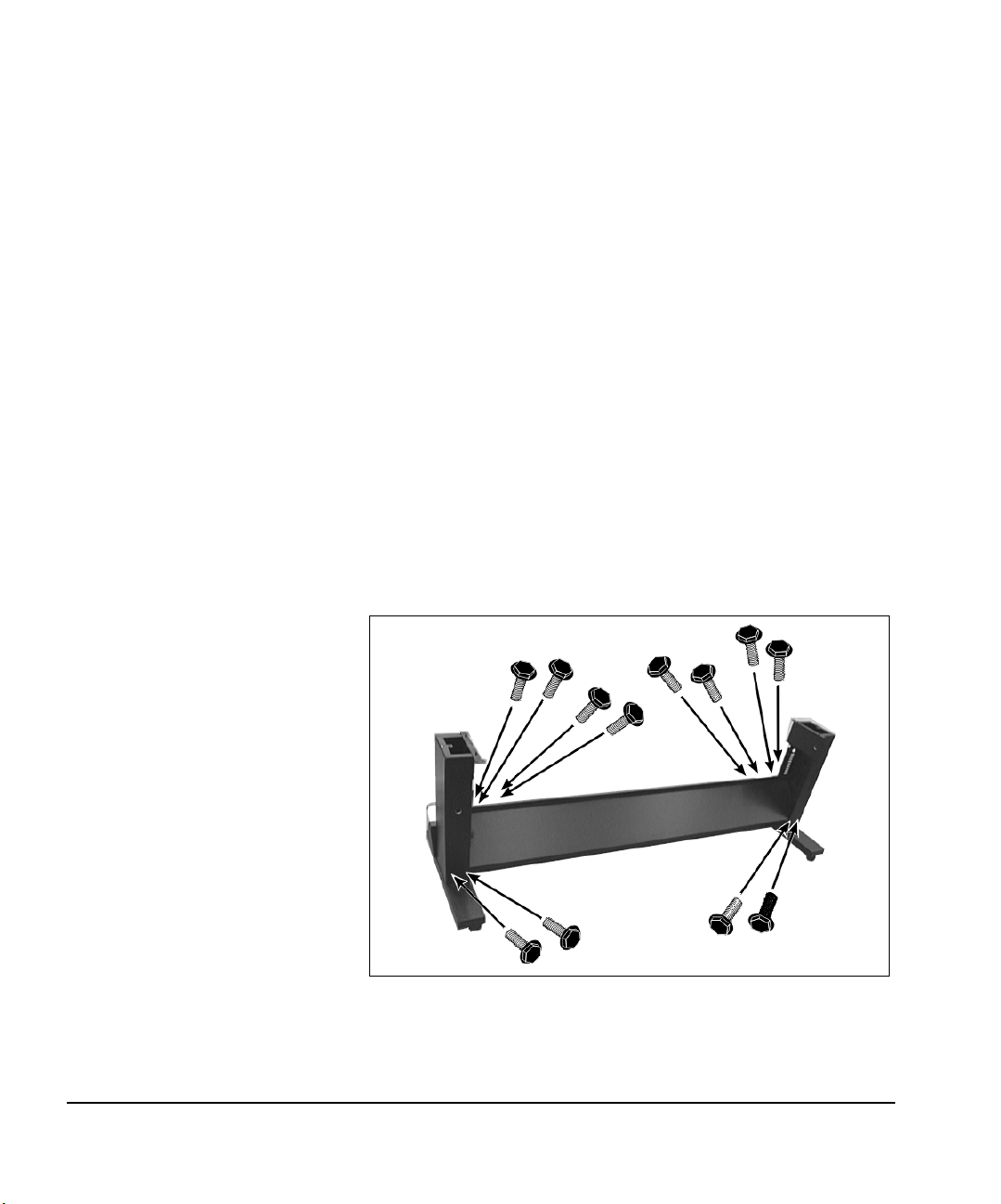
Stand Assembly 10. Locate the stand legs and the crossbar.
11. Lock the casters on both stand legs.
12. Using the twelve 10 mm hex-head screws provided, assemble
the stand (see Fig. 1-1).
Align the holes on the crossbar with the holes in the stand
legs, and attach the screws, but do not tighten them fully yet.
Fig. 1-1. Stand assembly
1-8 Unpacking and Assembly
Page 23
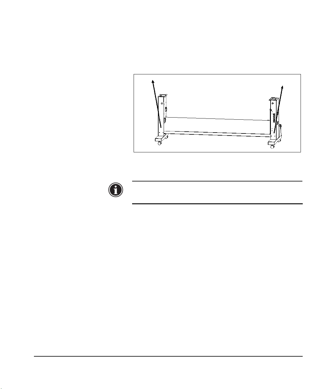
13. Bias the stand legs outward at the top, then tighten the
screws firmly (see Fig. 1-2) but not all the way.
With your foot braced against the outside of the left caster
support, gently tug the top of the stand leg toward you,
while a second person tightens the screws. Repeat this process with the right stand leg. This step is required to ensure
proper clearance for the media spools.
Fig. 1-2. Bias the stand legs outward as shown
(angle exaggerated for clarity)
Note
14. If purchased, install the VOC plenum kit.
Refer to the instructions included with the kit.
Leave the threading strings inside the stand legs. You
will use them later to pull the ink drain tubes
through the legs.
Unpacking and Assembly 1-9
Page 24
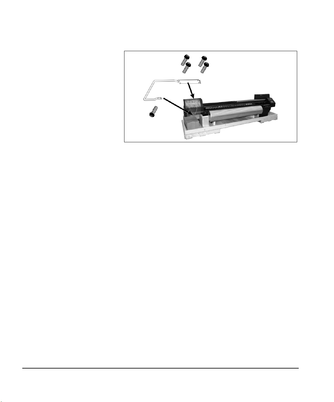
Printer Assembly 15. Attach the lift handle to the lef t end of the printer, using four
#2 screws on the back and one screw on the front (see
Fig. 1-3).
Fig. 1-3. Lift handle
16. Remove and discard the “DO NOT LIFT” label.
17. Detach the printer chassis from the pallet.
The printer chassis is attached with 10 mm hex-head bolts
and shock-absorbing washers to two wooden frames on the
pallet. Access the screws from the rear of the pallet.
18. Position the stand behind the printer.
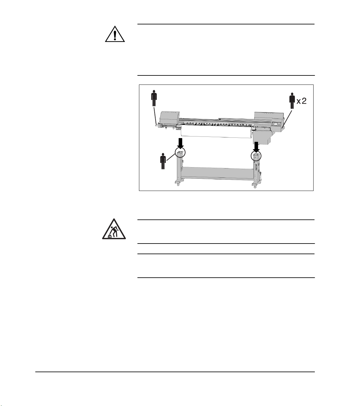
19. Lift printer straight up and lower onto the stand legs (see Fig.
1-4).
1-10 Unpacking and Assembly
Page 25
Caution
When assembling the printer onto the stand, be
careful to avoid damaging the turnbuckles underneath the postheater by allowing them to strike the
stand legs. The turnbuckles are precisely adjusted at
the factory, and will clear the stand legs by less than
one inch (25 mm) during assembly. Damaging them
could result in misalignment of the media path.
Fig. 1-4. Lowering the printer onto the stand
WAR NING
WAR NUNG
20. Align the two pins on each stand leg with the holes in printer
(see Fig. 1-5).
Have a fourth person perform steps 20 and 21 while three
persons hold the printer.
Unpacking and Assembly 1-11
The printer is too heavy to be lifted safely by one
person. At least three persons are required to lift the
printer.
Der Drucker ist zu schwer für eine Person. Mindestens 3 Personen sind erforderlich um den Drucker
anzuheben.
Page 26
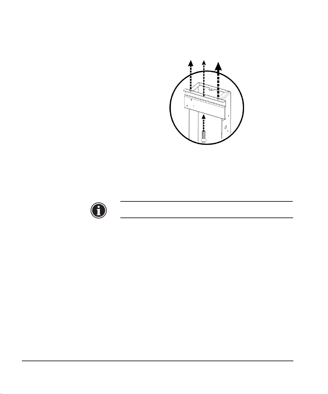
21. Align center hole on each leg (between pins) with center
hole in printer (see Fig. 1-5).
To speed this alignment, you can use a screwdriver inserted
into the holes in the stand and printer.
Fig. 1-5. Stand alignment
22. Lower the printer chassis onto the stand.
23. Ensure that the printer lies flat on both of the stand brackets.
Realign if necessary.
Note
24. Attach the printer to the stand with one silver #3 screw in the
center hole on each leg (see Fig. 1-5). Tighten all stand
screws securely.
The silver screws provide a ground path between the printer
engine module and the stand. Use an ohmmeter to verify a
ground path between the silver electronics box and the silver locating pin on the supply & takeup assembly, which is
visible on the stand leg facing the spools. Resistance should
be 5 ohms or less.
If the stand screws are not silver (in other words, “coated”),
the wrong screws were installed. Replace the stand screws
with the silver screws provided by MacDermid ColorSpan.
1-12 Unpacking and Assembly
The printer must lie flat on the stand brackets to
avoid media feed problems during printer operation.
Page 27

Caution
Failure to assemble the printer to the stand with silver screws could isolate the supply and takeup system from ground, which could result in damage to
the printer from electrostatic discharge.
Unpacking and Assembly 1-13
Page 28
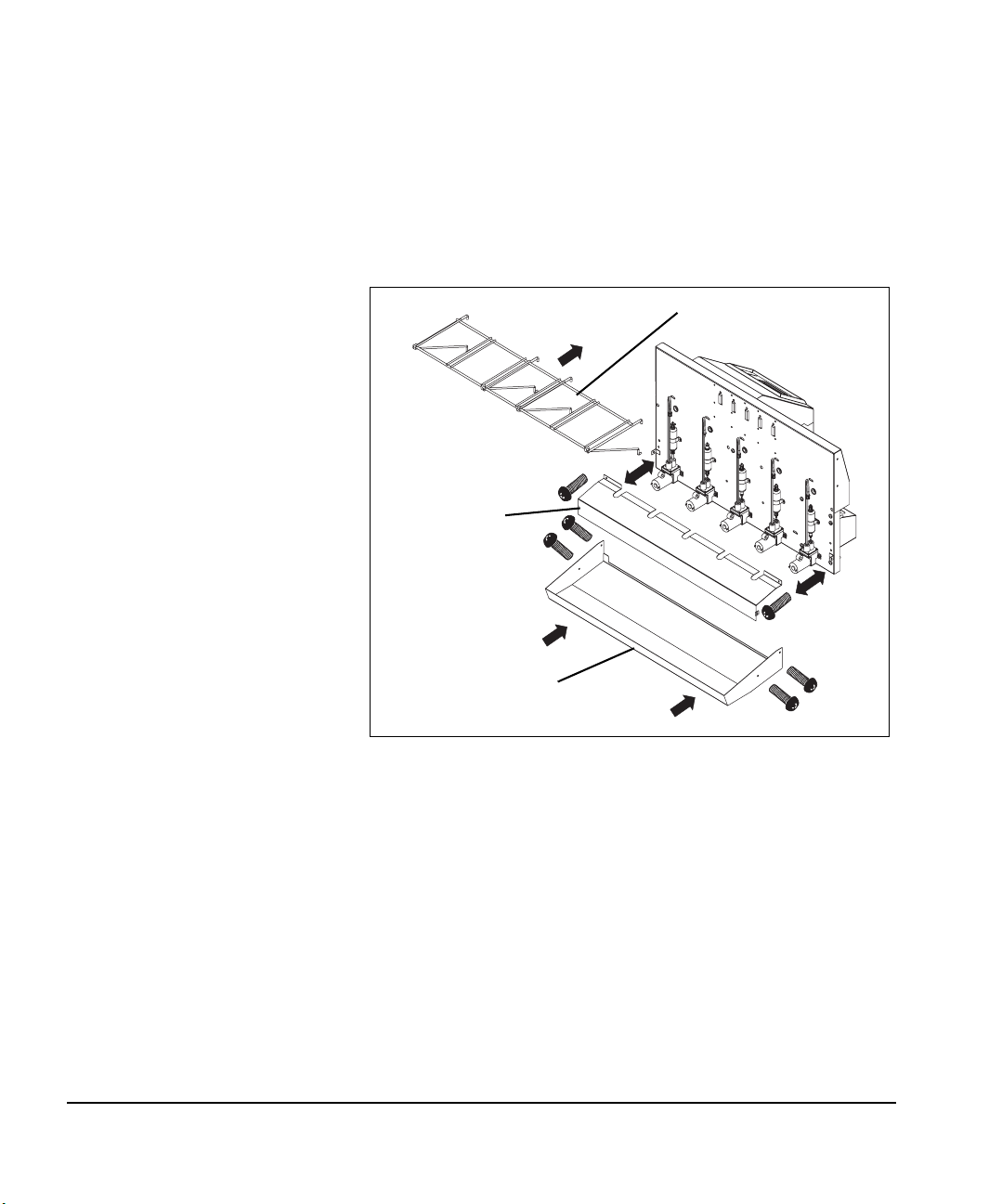
Off Head Supply (OHS)
Assembly
25. Remove the pump cover (see Fig. 1-6).
This is necessary to access the lower mounting holes for the
reservoir wire rack. The pump cover attaches to the printer
with two Phillips head screws.
26. Install the reservoir wire rack (see Fig. 1-6).
Insert the top pieces, hooks pointing down, into the mounting holes. Then insert the bottom pieces into the mounting
holes.
Reservoir rack
Pump cover
Catch tray
Fig. 1-6. Reservoir wire rack and ink catch tray
27. Reinstall the pump cover (see Fig. 1-6).
28. Attach the ink catch tray to the back of the printer with the
four #3 screws (see Fig. 1-6).
1-14 Unpacking and Assembly
Page 29
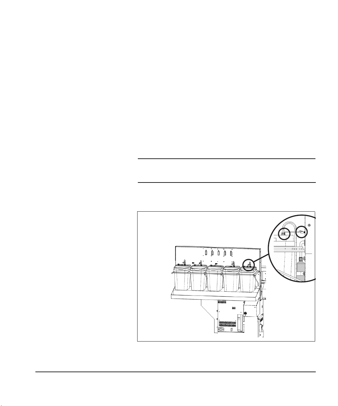
29. Install the five reservoirs.
You may want to wear gloves during this procedure to protect your hands from pigment ink stains.
◆ Place the reservoir into the wire rack. Match the color or
cleaning solvent label on the reservoir with the corresponding label on the printer.
◆ Remove the packing material from the ink level floats
inside the ink buckets.
◆ Unscrew the plastic seal on the hook-shaped tube
attached to the filter. Discard, or retain for subsequent
use. A small amount of ink may come out of the tube
(ink will be present in the tubes from factory testing).
◆ Connect the hook-shaped tube to the reservoir’s draw
tube, by pressing down until it seats with a click, and
turning the screw-on connector 3/4 to 1 turn. See
Fig. 1-7 below for location.
Note
◆ Connect the float sensor cable from the reservoir to the
Do not connect the hook-shaped tube to the air vent.
Doing so will result in no ink being drawn from the
reservoir.
data port on printer. See Fig. 1-7 below for location.
Fig. 1-7. Installing the reservoirs
Unpacking and Assembly 1-15
Page 30
Final Assembly 30. Install the vacuum reservoir (see Fig. 1-8).
Ensure that the o-ring is in place inside the reservoir opening, and screw on the reservoir. Hand tighten firmly, but do
not overtighten.
Fig. 1-8. Vacuum reservoir
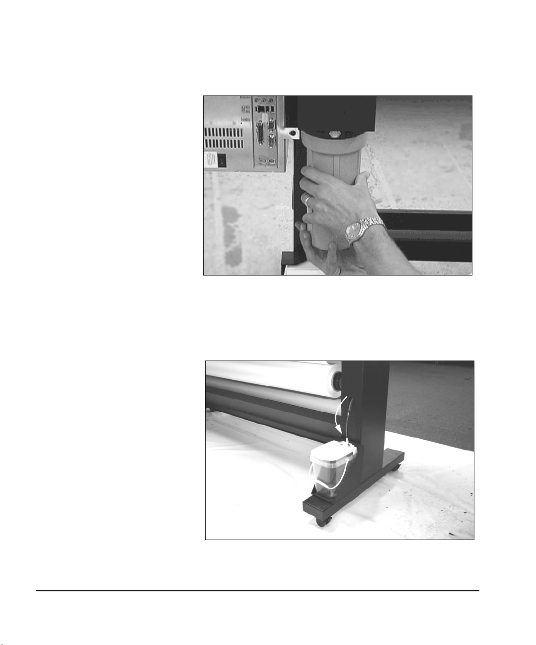
31. Using the threading string attached to the stand leg, pull the
drain tube that is connected to the left-side spittoon through
the stand leg to the rear of the printer, and connect it to the
left-side excess ink reservoir (see Fig. 1-9).
Fig. 1-9. Connecting the drain tube to the reservoir
1-16 Unpacking and Assembly
Page 31

32. Remove the front cover, and leave it off until the printer is
powered up and normal operation is verified.
33. Using the threading string supplied, pull the drain tube that
is connected to the right-side spittoon through the stand leg
to the rear of the printer, and connect it to the right-side
excess ink reservoir (see Fig. 1-10 and Fig. 1-11).
Fig. 1-10. Drain tube routing (with front cover removed)
Sensor cable
Drain tube
Fig. 1-11. Connect the excess ink sensor cable
Unpacking and Assembly 1-17
Page 32

Note
34. Connect the cable to the sensor on the excess ink reservoir
(see Fig. 1-11).
35. Connect the supply and takeup cable to the port on the side
of the electronics box (see Fig. 1-12).
As you look at the front of the printer, the port is located on
the left side of the electronics box, near two other cables
that area already connected to ports. Connect the cable
firmly to the port.
Ensure that the drain tube is fully attached to the reservoir with a “click.” Partial attachment will not
allow ink to drain into the reservoir, which will eventually cause the service station to overflow with
excess ink.
Supply & takeup cable
Fig. 1-12. Connecting the supply & takeup cable
36. Remove the two Phillips head screws on the front of the vacuum/pressure system cover, and remove the cover.
1-18 Unpacking and Assembly
Page 33

37. Connect the power cable to the connector on top of the vacuum/pressure assembly.
Fig. 1-13. Vacuum/pressure system with cable connection
(cover removed)
38. Reinstall the vacuum/pressure system cover.
39. (DisplayMaker 72SR only) Connect the cable from the mediaout sensor cable to the cable from the vacuum/pressure
system.
Both of these cables are marked with a label that says
“MEDIA SNSR.”
From sensor
From V/P system
Fig. 1-14. (DisplayMaker 72SR only)
Connecting the media-out sensor.
Unpacking and Assembly 1-19
Page 34

40. (Optional) Connect the optional VOC plenum to building
ventilation or VOC recovery equipment.
Install and connect the optional VOC plenum to a building
exhaust duct or charcoal filter device. Refer to the documentation that accompanies the kit for instructions.
41. Level and stabilize the printer.
Leveling the printer and removing its weight from the stand
casters is required to ensure proper media tracking and
high-quality prints. Locate the printer on a flat, level floor.
Lower all four leveling feet so they contact the floor, then
continue lowering them until the printer’s weight is off the
casters. Next, use a bubble level to ensure that both legs are
level front-to-back by adjusting the leveling feet (raise the
lower end, and keep the printer’s weight off the casters).
42. In the accessory kit, locate the two turnbuckles marked “A”
and “B.”
Caution
43. From the rear of the printer, install the turnbuckle marked “A”
to the location behind the postheater marked “A,” using the
turnbuckle pins and ring clips.
44. From the rear of the printer, install the turnbuckle marked “B”
to the location behind the postheater marked “B,” using the
turnbuckle pins and ring clips.
45. Check the ground path between the takeup spool and the
electronics box.
Set your ohmmeter to check continuity at low voltage (to
measure resistance of no more than 3 or 4 ohms). Touch one
lead to the takeup spool and the other lead to the steel cover
of the electronics box. Manually turn the spool a few rotations to make sure that the spool finger is engaged into the
supply & takeup shaft. A resistance reading greater than 2 or
3 ohms could indicate a ground path problem.
Do not turn the nut on the turnbuckle. Turning the
nut will change the post-heater alignment. If the nut
is turned, the post heater will need to be re-aligned
to ensure proper media tracking.
1-20 Unpacking and Assembly
Page 35

46. Check the ground path between the spool and the finger that
protrudes from the end of the spool. If this fails, replace the
spool.
47. Check the ground path between the electronics box and the
supply & takeup assembly.
Touch one lead to the stainless steel pin located between the
two Phillips-head screws above the spool collet on the
takeup. Place the other lead on the stainless steel cover of
the electronics assembly. If this fails, check the grounding
between the stand and the printer.
48. (Optional) Assemble and install the input and output tables
for rigid cut-sheet media.
If purchased, assemble and install the roller tables as
described in the documentation that accompanies them
(DisplayMaker 72SR Table Assembly Instructions, part number
0706246). The tables are designed to be easily attached to
and removed from the printer as needed for cut-sheet or roll
fed media.
Once assembled, position the tables as shown in the instructions. Use the supplied shock cords to secure the tables to
the printer.
To ensure smooth media advance, level the tables with the
platen, using a bubble level. Hold the level on top of and
perpendicular to the platen, over each table. Adjust the
table’s leveling feet until the top of the table is level with the
platen.
One of the roller bars on each table is not permanently
attached to the table frame. You can reposition this bar as
needed to support the far side of any width of media. Simply
slide the white plastic clips under the frame support to
secure the bar.
Unpacking and Assembly 1-21
Page 36

Connecting to Power See Appendix A, Technical Specifications, or refer to the Site
Preparation Guide, for detailed power requirements. Consult a
qualified electrician if you have any doubt as to how the circuits
in your facility can accommodate the printer and print server.
WARN ING
WARN UNG
The printer includes an auxiliary 24 volt power jack for the vacuum system. This option enables you to provide temporary
power to the vacuum system to prevent ink from flowing from
the printheads, in the event of a power failure or if the printer
must be powered down for maintenance. The power supply provided in the printer accessory kit includes interchangeable
adapter plugs for international use.
To provide battery backup power to the vacuum system, connect
the 24 volt power supply from the auxiliary power jack into a
UPS (uninterruptable power supply) that you purchase separately. To provide temporary power during maintenance, simply
plug the 24 volt power supply directly into a wall outlet (see
Appendix A, Technical Specifications, for detailed specifications).
WITH THE POWER SWITCH IN THE OFF POSITION,
POWER MAY STILL BE SUPPLIED TO THE PRINTER
COMPONENTS. To cut power completely from the
printer, you must unplug the power cords from the
power outlets.
WENN DER NETZSCHALTER IN OFF POSITION
STEHT, WIRD DEN KOMPONENTEN TROTZDEM
STROM ZUGEFÜHRT. Um den Drucker komplett
stromfrei zu machen, müssen Sie den Netzstecker
ziehen.
Fig. 1-15. Auxiliary vacuum power
1-22 Unpacking and Assembly
Page 37

Connecting to the
Print Server
Connect the printer to the print server with the included
VideoNet (for ColorSpan print servers) or Ethernet cable (nonColorSpan RIPs). See Fig. 1-16.
Note
Refer to the print server (RIP) documentation for further instructions on connecting the printer to the print server.
Do not connect the printer VideoNet cable to your
local area network. The VideoNet protocol is not
compatible with other network protocols.
Fig. 1-16. Power and RIP connections
Unpacking and Assembly 1-23
Page 38

First-Time Power-Up
and Test Print
After the printer is assembled and connected to power, you can
power up the printer, load media and ink, and print a test print.
Unpack the Printheads Have a paper towel ready to blot any cleaning fluid that has
escaped from the printheads and foam pad during shipping.
Most of the fluid should run off the SolaChrome Capping Film
into the drip tray.
1. Remove the shipping straps and shrink wrap from around the
carriage.
2. Remove the white shipping blocks on the sides of the capping station, and the white shipping pad between the capping station levers as shown in Fig. 1-17.
3. With the printhead carriage over the capping station as
shipped, tip the carriage back until it just lifts off the pad
below it.
Caution
Carriage
4. Remove the thin black foam pad that is pressed against the
printheads, and save it for future use.
When saturated with cleaning fluid, this pad can be used to
recover stubbornly clogged jets (see Cleaning Solvent Soak
on page 5-9).
Tipping the carriage back too far could damage the
encoder, requiring its replacement. Also ensure that
the encoder does not disengage from carriage.
REMOVE and
REMOVE
REMOVE
Fig. 1-17. Capping station as shipped
save thin pad
REMOVE
1-24 First-Time Power-Up and Test Print
Page 39

5. Remove and discard the Capping Film from the capping station.
6. Leave the capping station, in the lowered position.
7. Slowly lower the carriage back down over the capping station.
8. Move the carriage as needed to locate and remove the white
protective strips (for shipping) from the rail.
9. Fill the small squirt bottle (part number 0602448), located in
the accessory kit, with SolaChrome HR Cleaning Solvent.
You can use this squirt bottle to moisten a cloth to clean the
carriage, platen, and other parts of the printer. Use only a
100% polyester Class 100 cleanroom cloth to clean the
printheads.
Caution
Use of any solvents other than SolaChrome HR Cleaning Solvent could damage the printer and WILL
VOID THE WARRANTY.
10. At the service station (right end of the printer), squirt a small
amount of SolaChrome cleaning solvent into the entire length
of the wiper bar to loosen any dried ink and solvent.
Wiper bar
Fig. 1-18. Service station wiper bar
First-Time Power-Up and Test Print 1-25
Page 40

Power Up the Printer 1. Turn on the power switch to observe the typical power-up
sequence.
2. The control panel backlight illuminates. Move the contrast
lever (located to the right of the control panel screen) up and
down until the control panel graphics and messages are easily visible.
3. The printer runs a series of self-tests, and reports any errors it
finds.
4. The printhead carriage moves to the service station.
5. The control panel prompts you to load media.
6. You may load media or skip loading media for now. See
“Loading Roll-Fed Media” on page 3-14 for instructions.
7. The control panel displays the status screen.
1-26 First-Time Power-Up and Test Print
Page 41

Install Ink for the First
Time in the Printer
1. Shake each bottle of ink for one minute to redisperse the
pigments.
It is not necessary to shake the cleaning solvent.
The green “ready for refill” LEDs should be illuminated,
indicating that you may fill the reservoirs.
2. Empty the refill bottles into their corresponding reservoirs,
and install the profilers into their corresponding positions in
the docking station.
Profiler docking station:
Solvent Y M C K
Cleaning solvent Yellow Magenta BlackCyan
Fig. 1-19. Ink color locations
First-Time Power-Up and Test Print 1-27
Page 42

When you empty a refill bottle into a reservoir, the green
LED will blink until you install the corresponding profiler.
Then the LED will turn off. Do not refill the inks until the
green LED illuminates again.
3. After all four inks and the cleaning solvent reservoirs are full,
press the Online/Offline key to display the Front Page screen.
4. From the Front Page screen, press the (Menu) key to enter
the menu system.
5. Press the ) key repeatedly to highlight Maintenance.
6. Press the (Menu In) key to display the Maintenance menu.
7. Press the ) key repeatedly to highlight Fill Service Station.
8. Press the (Menu In) key.
The solvent trough in the service station fills with solvent.
9. From the Maintenance Menu, press the ) key repeatedly to
highlight Fill Heads With Ink.
10. Press the (Menu In) key.
The printheads are filled with cleaning solvent, emptied,
and filled with ink. This process takes approximately 30
minutes and is fully automated. During this process, occasionally check that the ink and cleaning fluid purged from
the printheads is draining into the service station’s excess
ink reservoir. If not, ensure that the drain tube is fully
attached to the reservoir (see page 1-18).
Load Media To load media in the printer for the first time, see “Loading Roll-
Fed Media” on page 3-14 for instructions. The printer ships with
a starter roll of media and a cardboard takeup core pre-loaded
on the spools.
Send a Test Print from
Server
1-28 First-Time Power-Up and Test Print
1. Install and set up the RIP.
Refer to the Quick Start Guide for the ColorSpan print server,
or the manual that accompanies the third party RIP you will
be using.
2. Run the jet health routine to detect, recover, and replace
unrecoverable jets.
See “Checking Jet Health” on page 3-6 for instructions.
3. Send a test print from the ColorSpan server or RIP to the
printer, to verify your installation.
Page 43

What’s Next? ◆ To familiarize yourself with the printer, refer to the remain-
der of this chapter.
◆ For a complete description of using the control panel, see
Chapter 2, Using the Control Panel.
First-Time Power-Up and Test Print 1-29
Page 44

Workflow Overview
Daily Startup 1. Uncap the printheads (for instructions, see “Uncap the Print-
heads” on page 3-12).
This procedure includes, while the carriage is still at the capping station, wiping the printheads with SolaChrome HR
Cleaning Solvent, using a 100% polyester Class 100 cleanroom wipe. DO NOT USE ISOPROPYL ALCOHOL ON THE
PRINTHEADS.
n
p
2. Ensure the functioning or substitution of all inkjets (for
instructions, see “Checking Jet Health” on page 3-6):
◆ Print Prime Bars
◆ Run Purge-n-Wipe
◆ Repeat once or twice to recover missing inkjets
3. Map out missing jets (see “AutoJet” on page 4-3 or “Manual
o
Jet Mapping” on page 4-15).
Under normal circumstances, these procedures should adequately prepare the printer to print. For instructions on recovering stubbornly clogged printheads, see “Cleaning Clogged Ink
Jets” on page 5-8.
Printing When the printer is connected to a ColorMark Pro print server,
here is how a ty pical print job progresses from the client workstation to the printer. If you are using a non-ColorSpan RIP, refer
to the documentation that accompanies it for details.
1. The operator sends a file to be printed from a client
workstation.
2. The print job is received by the print server.
Once it reaches the print server, the print job may be reprioritized, combined with other jobs, re-routed, or otherwise
manipulated. Refer to the print server online help or manual
for instructions.
3. The print server RIPs the job.
The raster image processing (RIP) process translates the
PostScript language data that comprises the print job into
the data required by the printer.
1-30 Workflow Overview
Page 45

4. The server sends the image to the printer for printing.
Printing can be paused and resumed at the control panel,
enabling you to purge the printheads to recover jets or make
other adjustments. During the pause, the carriage goes to the
service station and idle spits.
Daily Shutdown 1. Cap the printheads (for instructions, see “Capping the Print-
heads” on page 3-11).
2. DO NOT POWER DOWN THE PRINTER.
If the printheads will be capped longer than overnight, follow
the instructions under “Daily Startup” twice a week to prevent
excessive ink clogging, then recap the printheads. If this is not
possible or impractical, or if the printer must be shipped, see
“Extended Power Down and Restart” on page 5-21 for instruc-
tions.
For further idle maintenance tips, see “Idle Jet Maintenance” on
page 3-3.
Workflow Overview 1-31
Page 46

Parts Overview
13
12
19
14
4
5
11
15 & 16
11 b
17
18
29
26
61 2 3
5
10
11 a
7
15 & 16
27
8
9
20
25
24
21
23
22
28
Fig. 1-20. Major parts of the printer
1-32 Parts Overview
Page 47

Index Description
1Encoder strip — allows precise positioning of the print-
head carriage across the length of the platen.
2 Main carriage drive belt — moves the carriage across
the length of the platen.
Transport chain (not shown) — supports the ink sup-
ply tubes that carry ink from the ink reservoirs to the
printheads, power, and electrical signal cables.
3Platen — supports the media under the printheads
during printing, warms the media in the print zone,
includes vacuum to hold the media against the platen.
4 Printhead carriage — carries the printheads, digital
imaging sensor, and photodiode across the length of
the platen.
Digital image sensor (on carriage, not shown) —
detects the location of printed pixels for precise alignment of the printheads, enables the automatic replacement of poorly-printing ink jets with substitute jets.
Photodiode (on carriage, not shown) — enables the
creation of color transforms without an external spectrophotometer (requires print server support), and the
linearization of existing transforms.
5 Spittoons — located at both ends of the platen,
receives ink “spits” that keep the printheads at their
optimal performance.
6AutoClean
TM
Service station — catches purged ink
from the printheads, wipes the printheads with cleaning solvent. Wipers are automatically cleaned and
cleaning solvent applied before wiping. Ink is periodically spit when idle to keep the inkjets working.
7 Ready-for-Refill LEDs — illuminates when there is room
for a refill bottle of ink, or when the cleaning solvent
reservoir is empty. Blinks when either the ink has been
refilled and profiler not replaced, or when the profiler
has been replaced but the ink has not been refilled.
8 Control panel — displays messages and allows control
of certain printer operations. Includes a contrast adjustment lever and audio feedback.
9Electronics module — contains the printer’s power
supply and control electronics.
Parts Overview 1-33
Page 48

Index Description
10 Post he at e r — helps to dry the output prior to the
takeup. Incorporates turnbuckles that can be adjusted
to straighten the media path.
11 Pinch rollers (23 places) — grip the media during
loading and printing. If installed, a pinch roller adjust-
ment lever (11a) allows you to adjust the force or
release the pinch rollers to feed rigid cut-sheet media.
A media out sensor (11b) detects whether media ig1
s loaded.
12 Capping station — protects the printheads from drying
out while idle (not printing) for extended periods.
13 H a n d l e — for pulling the printer on its casters and lift-
ing the end of the printer.
14 S t an d — supports the printer.
15 Casters (four places) — enables easy relocation of the
printer, can be locked in place.
16 Leveling pads (four places) — allows the printer to be
stabilized and leveled for consistent media feeding.
17 Docking station — holds the profilers, one for each res-
ervoir, that track ink and cleaning solvent usage, and
identify ink characteristics for the RIP.
18 Off-Head System (OHS) — reservoirs, electronics, vac-
uum (to maintain negative head pressure), and pressure (for purging the printheads) that provide ink and
cleaning solvent for cleaning the printheads.
19 Ink filters — user replaceable, one for each reservoir, fil-
ters out impurities from the ink or cleaning solvent
prior to being sent to the printheads.
20 Ink reservoirs — holds the ink and cleaning solvent
supply, 3.5 liter capacity.
21 Power inlet — connects the printer to electrical power.
22 Standby power switch — places printer in standby
mode (to disconnect from power, disconnect power
cord).
23 VideoNet port — connects printer to print server.
24 Vacuum/Pressure (VP) assembly — provides vacuum
and pressure to the OHS and printheads.
25 Media supply and takeup system — drives and pro-
vides tension to the media supply and takeup spools.
26 Media advance switch — enables user to advance
media forward or backward during loading.
1-34 Parts Overview
Page 49

Index Description
27 Preheater — warms the media for optimal printing.
28 Excess ink containers — collects ink from the spittoons
and service station.
29 Auxiliar y 24 volt power jack to vacuum system —
accepts the supplied 24 volt DC power supply to the
vacuum system, which can be connected to a user-supplied UPS for temporary battery backup power in the
event of a power failure, or to a wall outlet for temporary power during maintenance that requires the rest of
the printer to be powered down. See Appendix A, Technical Specifications, for details.
Parts Overview 1-35
Page 50

Special Features The printer has many advanced features to help you produce the
best printed output with the least effort.
Printheads ◆ Micro-Quad
TM
printheads — sixteen 600 dpi, 30 picoliter
piezoelectric printheads (four per color).
◆ AutoClean
TM
service station — a motorized service station
that wipes the printheads with cleaning solvent automatically to keep all jets firing properly.
◆ Purge-n-Wipe
TM
— combines an air pressure purge with a
cleaning solvent wipe of the printheads to recover clogged
jets.
◆ AutoRecover — performs a Purge-n-Wipe at the start of a
print job (before printing) if a Purge-n-Wipe has not been
performed for a specified amount of time.
◆ Automated printhead maintenance — to keep individual
inkjets from drying out, the printer periodically “spits” a
small amount of ink and performs a Purge-n-Wipe cycle.
◆ Capping station — manually-operated capping station prevents drying out of printheads when idle. The printer senses
the position of the capping station to prevent carriage movement while capped, or to prevent the carriage from moving
to the capping station if it is raised.
Ink System ◆ Off-Head System (OHS) — bulk ink and cleaning solvent res-
ervoirs allow refilling without taking the printer offline, even
during printing. The printer displays an alert when ink or solvent can be refilled.
◆ Onboard vacuum/pressure (VP) system — provides vacuum to maintain negative printhead pressure, and air pressure to purge the printheads or ink tubes without removing
them from the printer.
1-36 Special Features
Page 51

Calibration The Advanced Automation Eye uses a high-resolution imaging
sensor, colorimetric photodiode, and embedded software to
align the printheads, detect and replace missing jets, linearize
output, and color profile media.
◆ AutoSet
TM
calibration — uses a high-resolution digital imag-
ing sensor to automatically align printheads bidirectionally
for precise positioning of ink jet pixels, and runs AutoJet.
◆ AutoJet
TM
calibration— compensates for lost or misfiring jets
by locating them and using substitute jets without slowing
printing speed.
◆ AutoTune
TM
scheduling — runs Purge-n-Wipe and/or AutoJet at user-defined intervals, for highest quality during unattended printing. Optionally, if unsubstituted non-working
jets are found, printing stops until the problem is corrected.
◆ Automatic color calibration — uses an onboard photodiode
to linearize output over the entire density range (with print
server or RIP support).
◆ Color profiling — with print server or RIP support, the
onboard photodiode can be used to create custom Color-
®
Mark
and ICC color profiles for third-party media.
Media Handling ◆ Tensioned roll-to-roll media handler — supply and takeup
spools are tensioned to manage vinyl medias on heated surfaces. Tensioning is automatically maintained consistently on
the supply and takeup as the roll diameters change during
printing. Optionally, the supply or takeup motors can be
idled during printing. In roll-fed mode, the supply must be
loaded, but the media can optionally be left off the takeup.
◆ Steel media spools — the takeup supports up to 7.5 inch
(190.5 mm) diameter rolls of vinyl media on 3-inch cores.
The supply can also accept 2-inch cores with the supplied
2-inch collets.
◆ Rigid cut-sheet option — if installed, this combination of
hardware and software enables printing on rigid cut-sheet
media up to 3/16 inch (4.76 mm) thick.
◆ Media width sensing — automatically detects the width and
position of the media loaded, for precise image placement.
◆ AutoEdge — automatically aids the loading of rigid sheets by
detecting right, left and leading edges, and warns the user if
the sheet is skewed.
Special Features 1-37
Page 52

◆ Integrated contact heaters — preheater and platen heater
maintain uniform surface temperature across the printing
area to control dot gain on various media. Heated drying
surface allows prints to dry before being rolled onto the
take-up spool (results may vary based on media and color
profile characteristics).
Performance and
Ease-of-Use
◆ Media Wizard — stores and recalls a set of operating parameters by media type and print mode, for optimal printing
performance. Includes a set of predefined settings for standard media; user may add settings for other media.
◆ Speed/quality print modes — three print modes provided to
meet job and business requirements of speed and quality.
◆ Simplified control panel interface — Front Page screen presents frequently-used functions, with recommended preset
configurations. A menu provides access to less-frequently
used functions and troubleshooting help.
◆ User assistance — control panel features online help, interac-
tive procedures, and diagnostics to assist the user “on-thefly,” reducing training and troubleshooting time.
◆ Integrated Warning/Action system — the ATTN (Atten-
tion) key blinks on the control panel when the printer
detects an error condition, potential error condition, or when
you make a change that suggests recalibration or other
action to ensure best print quality. There are two types of
ATTN messages:
◆ Actions — the printer has detected an error condition
that stopped printing or will prevent printing from starting. You must correct the error before the printer will be
ready to print. When the printer senses that the error
condition has been addressed, the Action will be deleted
the next time the ATTN key is pressed.
◆ Warnings — the printer has detected a condition that, if
left unaddressed, could result in substandard prints or a
condition that will require an action before printing can
continue. Any action on your part is optional; printing is
not interrupted for a Warning message.
1-38 Special Features
Page 53

CHAPTER 2
Using the Control Panel
This chapter describes the functions of the control panel.
◆ Overview (page 2-2)
◆ Front Page (page 2-4)
◆ Navigation Keys (page 2-8)
◆ Menu (page 2-9)
◆ Menu Tree (page 2-17)
Using the Control Panel 2-1
Page 54

Overview The touch-screen control panel shows you the printer’s current
status, and enables you to interact with the printer when changing media and ink, respond to an error condition, or configure
options. There are three main control panel screens:
◆ Ready (Status) Screen
◆ Front Page
◆ Menu
Ready Screen When you press the Online/Offline button from the Front Page
screen, the printer goes online and the Ready screen appears.
The Ready screen displays the current status of the printer and
any currently printing job. It displays when the printer is online
(communicating with the print server) and either ready to print
or printing.
Fig. 2-1 Ready screen
Front Page When you press the Online/Off line button from the Ready
Screen, the printer goes offline and the Front Page screen
appears. This screen is the top level of the printer’s menu system. It provides access to the most frequently-used offline functions. For details, see “Front Page” on page 2-4.
Menu When you press the Menu key on the Front Page screen, the
Menu appears. The Menu provides access to advanced configuration options. For details, see “Menu” on page 2-9.
2-2 Overview
Page 55

User Assistance The control panel provides various forms of online user
assistance:
The ? button provides an explanation of the current function,
with some guidance for what to do next.
The ATTN (Attention) key blinks on the control panel when the
printer detects an error condition, potential error condition, or
when you make a change that suggests recalibration or other
action to ensure best print quality. There are two types of ATTN
messages:
◆ Actions — the printer has detected an error condition that
stopped printing or will prevent printing from starting. You
must correct the error before the printer will be ready to
print. When the printer senses that the error condition has
been addressed, the Action will be deleted the next time the
ATTN key is pressed.
◆ Warnings — the printer has detected a condition that, if left
unaddressed, could result in substandard prints or a condition that will require an action before printing can continue.
Any action on your part is optional, printing is not interrupted for a Warning message.
When the printer issues one of these messages, the ATTN key
will blink, and an alert beep will sound (unless disabled, see
page 2-14). Press the ATTN key to display a list of message titles,
and select a title to display a detailed cause-and-recovery screen.
If you choose to not correct a Warning condition and resume
printing, the ATTN key will remain displayed, but will not blink
until the printer issues a new Warning or Action message. The
messages can be dismissed by correcting the condition, or by
pressing the applicable key on the detail screen.
Tip
Overview 2-3
See page 2-13 for instructions for choosing an Expert
or Novice mode for displaying these messages
(Expert mode routes most messages to the Actions &
Warnings menu), and for disabling or enabling the
audible alarm. See the table beginning on page B-8
for a list of errors and recovery procedures.
Page 56

Front Page The Front Page provides access to the most frequently-used
printing and maintenance f unctions. For advanced configuration options, press the Menu key (see “Menu” on page 2-9 for
instructions).
Fig. 2-2. Front Page
◆ Printer Name — displays the name of the printer as defined
on the print server.
◆ Online/Offline — returns the printer to the Ready screen,
when it is online and ready to receive print jobs.
2-4 Front Page
Page 57

◆ Media & Ink — displays a listing of the media and ink cur-
rently installed in the printer. Press the ) and , keys to
highlight “Media” or one of the inks, then press ! (Pro-
ceed) to display information about the selection. From this
screen, you can press the and keys to scroll between
screens. Press ! (Proceed) to return to the list, then
(Menu Out) to display the Front Page screen.
Fig. 2-3. Media Info, Ink Info screens
Front Page 2-5
Page 58

◆ Status — displays system parameters and the status of all
user-configurable options. Press the and keys to scroll
between pages. To change an option, go to the Printer Configuration section of the menu.
Fig. 2-4. Status page 1
◆ Print Mode — sets print quality mode. See “Selecting a Print
Mode” on page 3-4 for instructions.
◆ Advance Media — press the ) key to advance the media forward. When you press and hold the ) key, the media moves
faster. Press the , key to reverse the media back onto the
supply spool. When you press and hold the , key, the media
moves faster. You can also press the Media Advance rocker
switch, mounted on the OHS near the postheater, to move
the media in either direction.
◆ Menu — displays the complete printer menu for access to
advanced configuration options (see “Menu” on page 2-9
for instructions).
◆ AutoJet — detects deflected and non-firing jets, and substi-
tutes working jets for them (in Production and Quality
modes).
◆ Prime Bars — fires all jets by drawing a set of lines called
prime bars. This is a good way to inspect and prepare the
jets for printing after they have been idle (see “Print Prime
Bars” on page 3-7). You can also print a similar pattern
called Print Jet-Out Lines, which shows which jets have been
detected and replaced by AutoJet (see page 2-14 for details).
2-6 Front Page
Page 59

◆ Purge — performs a Purge-n-Wipe, which purges the print-
heads then wipes them in the service station, to help recover
missing jets. Print a prime bars pattern to verify jet recovery.
See “Loading Roll-Fed Media” on page 3-14 for instructions.
◆ Sleep (visible when heads are not capped) — verifies that the
capping pad is disengaged (in the lower position), the
printer turns off the heaters, detensions the media, and disables the OHS. When you manually engage the capping
levers, the capping pad sensor is detected and the control
panel disables most functions except for Wake. See “Cap the
Printheads” on page 3-11 for instructions.
◆ Wake (visible when the printheads are capped) — the opera-
tor lowers the capping pad, then selects this option to restore
the printer from standby mode, enable the OHS, and move
the printhead carriage back to the service station (at the far
right end of the printer). When the printheads are uncapped,
the control panel is fully functional. See “Uncap the Printheads” on page 3-12 for instructions.
◆ Access Heads — moves the printhead carriage out from the
service station to the capping station. This is the same functionality as the Access Printheads option on the Maintenance menu.
◆ Media Wizard — provides direct access to the printing
parameters stored for the currently loaded media (see
“Media Wizard” on page 3-31 for details).
◆ Load (visible when the supply and takeup are unloaded) —
enables you to load media on the supply and/or takeup, and
properly tensions the system. See “Loading Roll-Fed Media”
on page 3-14 for instructions.
◆ Unload (visible when the supply and takeup are loaded) —
detensions and enables you to unload the supply and takeup
system. See “Unloading and Cutting Roll-Fed Media” on
page 3-21 for instructions.
◆ Reload — enables you to load another roll or sheet of the
previously printed media with the same settings, without
stepping through the media load process.
◆ AT TN (Attention)— blinks on the control panel when the
printer detects an error condition, potential error condition,
or when you make a change that requires recalibration or
other action to ensure best print quality. See “User Assistance” on page 2-3 for further details.
Front Page 2-7
Page 60

Navigation Keys The following table shows you how to move through the menu
system and perform printer control functions.
Key Description
,)
+*
Menu In — selects the highlighted menu option.
!
(
"(
'
Display Menu — displays the printer menu.
Menu Up/Down — moves the menu highlight up and
down the menu.
Menu Top/Bottom — moves the menu highlight to the
top or bottom for the menu.
Menu Out — moves to the next higher menu in the
hierarchy.
Back/Forward — moves between pages or screens, or
selects between other options.
Proceed — initiates the selected function.
Help — displays a summary description of the high-
lighted menu options.
Pause/Resume — pauses or resumes printing during a
calibration.
Cancel — cancels the current menu function or choice.
Yes/No — indicates a Yes or No.
Continue (error screen) — proceeds to the next step in
a troubleshooting dialog.
Ignore (error screen) — specifies “ignore” in a trouble-
shooting dialog.
Retry (error screen) — specifies “retry” in a trouble-
shooting dialog.
Reboot Printer (error screen) — specifies “restart
printer” in a troubleshooting dialog.
Information (error screen) — displays further informa-
tion about the error.
2-8 Navigation Keys
Page 61

Menu The menu has these main sections:
◆ Calibrate Printer (see below)
◆ Printer Settings (page 2-10)
◆ Maintenance (page 2-14)
◆ Service Printer (page 2-16)
◆ User Diagnostics (page 2-16)
◆ Warnings & Actions (page 2-16), shown in Expert Messages
Mode only
This section explains each of the functions on the printer menu.
See “Men u Tree” on page 2-17 for a listing of all menu options.
Calibrate Printer For details on these options, see Chapter 4, Calibrating the
Printer.
◆ Auto Calibrations — see “Auto Calibrations” on page 4-7 for
instructions.
◆ Auto Bidi Calibration — ensures that every working jet
fires a pixel at precisely the same location, in both directions of travel
◆ Auto H2H Calibration — aligns the printheads relative to
each other
◆ AutoJet Calibration — locates and substitutes missing jets
for working jets
◆ Full AutoSet — runs AutoJet and AutoBiDi in sequence
Menu 2-9
Page 62

◆ Manual Calibrations — allows you to calibrate the printer
visually, without the printer’s digital imaging sensor. Inaccurate judgments by the operator during these tests could
result in substandard output. See “Manual Calibrations” on
page 4-8 for instructions.
◆ Media Feed
◆ Manual Bidi Registration
◆ Manual X Head Registration
◆ Manual Jet Mapping — the manual version of AutoJet
◆ Jet Status Lines — prints the Manual Jet Mapping pat-
tern without running the calibration
◆ Default Registration Data
◆ AutoTune — schedules jet maintenance to run automatically
after a certain number of prints have printed. See “AutoTune” on page 4-4 for instructions.
◆ AutoRecover — performs a Purge-n-Wipe at the start of a
print job (before printing) if a Purge-n-Wipe has not been
performed for a specified amount of time. See “AutoRecover” on page 4-6 for instructions.
◆ Calibration Summary — prints summary information with
the AutoSet calibration test patterns, or transmits registration or jet data to a log file on the print server. “Calibration
Summary” on page 4-22 for details.
◆ Configure for Profile Creation (cut sheet printing only) —
causes all calibration prints to print on the same cut sheet,
rather than ejecting the sheet after each calibration print.
Automatically disabled after all calibration prints are finished, when a print job is received from the RIP, or when rollfed media is loaded. Also allows you to configure a dry time
before calibration readings are taken.
Printer Settings Printer Settings enables you to set many options that control
how the printer operates. Settings saved by the Media Wizard are
indicated by
MEDIA WIZARD ◆ Takeup Tension — adjusts the media takeup tension, which
is required for proper media feeding. Insufficient takeup tension could result in inaccurate media feed and media buckling.
MEDIA WIZARD ◆ Supply Tension — adjusts the media supply tension, which is
required for proper media feeding. The lowest (“idle”) tension is best for most media.
2-10 Menu
MEDIA WIZARD in the margin.
Page 63

◆ Supply Out Detection — for roll-fed media, the printer usu-
ally monitors the supply spool to detect when it runs out of
media. You can use this menu option to disable media out
detection when you keep the takeup spool pin release tool
(part number 0504334, see “Takeup Spool Pin Release” on
page 3-22 for instructions) installed for printing rather than
to freely pull a small amount of media from the supply.
MEDIA WIZARD ◆ Heater Temp Settings — selects one of several pre-defined
temperatures, plus one custom, user-defined setting. Excessively high heat could cause the media to deform or stick to
the platen, while not enough heat could result in partially
dried prints. For instructions, see “Setting Heater Temperatures” on page 3-34.
MEDIA WIZARD ◆ Platen Vacuum Control — turns on the vacuum fans, then
allows you to raise or lower the fan speed. Raise the speed if
the media is rising off the platen, lower the speed if the
media is buckling or wrinkling. Turn off the vacuum for lightweight media such as paper or fabrics.
MEDIA WIZARD ◆ Drying Delay — a drying delay slows throughput (media
advance speed) to allow prints to dry more thoroughly.
Select the shortest delay that permits complete drying.
◆ Excess Ink Sensor — enables you to disable the excess ink
sensor if it is malfunctioning, or enable it after it has been
replaced. When the sensor in the excess ink reservoir under
the supply reservoirs indicates that the reservoir is full, it
generates an Action message on the control panel, and printing cannot proceed. Do not disable the sensor unless a malfunction erroneously prevents printing.
◆ Capping Station Sensor — allows you to disable the cap-
ping station sensor if it is malfunctioning, or enable it after it
has been replaced.
◆ Media Out Sensor (72SR) — allows you to disable the input
table’s media out sensor if it is malfunctioning, or enable it
after it has been replaced. Use care when printing with this
sensor disabled, to avoid printing on the platen or striking
the carriage against the media.
◆ Gutter Settings — determines the appearance of the top and
side gutters:
◆ Top Gutters — allows you to turn On or Off the gutter
pattern at the top edge of the print, which shows data
Menu 2-11
Page 64

about the print such as date and time printed and print
mode, plus write-in blanks for other data.
Fig. 2-5. Top gutter data
◆ Side Gutters — sets the side gutter pattern to Narrow,
Medium, or Wide sizes, or turns them Off. Side gutter
patterns help keep the ink jets open by firing ink
through them in a pattern outside the printed image
area. You can print gutters on the left side only of the
media (closest to the capping station), or both sides.
Printing on the left side only reduces ink usage, while
printing on both sides can keep the inkjets clearer. Using
this feature decreases the width available for printing the
job.
◆ Left Platen Gutter — determines when the jets will fire in
the left spittoon to keep all jets firing correctly. Turning
off this function may speed throughput with narrower
media, since it allows the carriage to turn around before
reaching the end of the platen, but it may also necessitate more frequent Purge-n-Wipe operations to clear
clogged jets. Always On fires the jets in the spittoon
with all media widths. For Narrow Media Only fires the
jets in the spittoon only if the media is less than 40
inches wide. For Wide Media Only fires the jets only if
the media is less than 72 inches wide. Off for All Media
disables spittoon firing for all media widths.
◆ Platen Gutter Spits — sets the amount of ink used by the
maintenance spits to High, Medium, and Low. To conserve ink, use the lowest setting that keeps the jets open.
The default High.
◆ Margin Settings
◆ Space Between Prints (roll-fed) — sets the blank space
between print jobs, between 0 and 10 inches (25 cm).
◆ Right and Left Margin — sets the amount of blank space
for the right and left margins, between 0 and 5 inches
(13 cm).
◆ Leading Margin (cut-sheet) — sets the amount of blank
space at the leading edge of cut-sheet media.
2-12 Menu
Page 65

◆ Trailing Margin (cut-sheet) — sets the amount of blank
space at the trailing edge of cut-sheet media.
◆ Media Measure Type — for cut-sheet media, you can choose
one of three levels of precision for finding the left, right, and
front edges of the media.
◆ Minimal — measures the width of the media once, and
finds the front right edge
◆ Standard — measures the width of the media once, and
finds the right and left front edges to estimate skew
◆ Maximal — measures the width of the media in two
places, and finds the right and left front edges to estimate skew and detect non-rectangular sheets
Choose Minimal for fastest throughput with media in perfect condition, Maximal for greatest precision and skew
detection when printing edge-to-edge.
◆ Quality Check — determines how AutoTune errors are han-
dled (see “AutoTune” on page 4-4 for information about
AutoTune).
◆ Print Position — when the printed image does not span the
entire width of the media, positions the printed image flush
right (nearest the control panel), flush left (nearest the capping station), or centered on the media.
◆ Stif f Roll-Fed Media Handling — when enabled, detensions
then retensions the takeup system before every print job, for
more accurate feeding of adhesive-backed and other stiffer
roll-fed media types.
◆ Standby Wait — sets the period of time to wait for a print job
before going into standby mode, which turns off the heaters and detensions the supply and takeup system.
◆ Expert/Novice Messages — Novice mode presents Warn-
ings (alerts that do not prohibit printing) and Actions (conditions that require user intervention before printing can
proceed). Expert mode presents Actions only, presents fewer
“press Proceed” prompts af ter an Action has been addressed.
The default is Novice mode.
When in Expert mode, active Warnings and Actions can be
displayed by selecting Warnings & Actions from the menu,
since Warnings will not cause the ATTN icon will appear in
Expert mode. See “User Assistance” on page 2-3 for further
information about Actions and Warnings. See “Warnings &
Actions” on page 2-16 for further information about this
menu option.
Menu 2-13
Page 66

◆ Audible Alarm — enables and disables the audible alarm
beep that sounds with Warning and Action messages.
◆ Units — sets English or Metric units of measure for data dis-
played by the control panel.
◆ Head Height — moves the printhead carriage over the platen
so you can adjust the head height. See “Set the Printhead
and Camera Height” on page 5-11 for instructions.
◆ Service Station — allows you to set the alignment and height
of the service station wipers. For instructions, see “Calibrate
the Service Station” on page 5-16.
◆ Air Purge Type — you can perform a 4-color purge and the
AutoTune purge with all four colors at once (“Standard
Purge”) or one color at a time (“Performance Purge”). The
Performance Purge occurs at a higher pressure than the
Standard Purge.
◆ Automatic Eject (cut sheet printing only) — when enabled,
the sheet is automatically ejected at the end of the print job.
When disabled, the next job(s) will print on the same sheet
until there is no more room to print.
◆ Printer Name — displays a keypad to change the printer
name displayed on the control panel and RIP or ColorSpan
Print Ser ver.
◆ Idle Spits — when the printer is idle, it automatically spits a
small amount of ink into the service station to keep the inkjets open and working. To reduce the amount of ink consumed during idle spitting, you can set the operation to
Medium or Low. To ensure that the printheads are always at
maximum readiness, use the High setting.
◆ Restore All Defaults — restores all Printer Configuration settings to their factory default values, and zeroes all registration data. After running this option, all calibration values
must be reestablished by running AutoSet or manual calibrations.
Maintenance ◆ Access Printheads — moves the printhead carriage out from
the service station to the capping station. This is the same
functionality as the Access Heads button on the Front Page.
◆ Purge A Color — purges the four printheads of a single color,
rather than all sixteen printheads. This is helpful when recovering stubborn jet-outs.
◆ Print Jet-Out Lines — prints a version of the prime bars (see
page 2-6), in which missing jets that are replaced are
marked with a black square.
2-14 Menu
Page 67

◆ Print Media Skew Lines — prints a swath of parallel lines
across the width of the media, in alternating directions, continuously until you stop the print. If the swaths are not parallel to each other, the media is skewed (not feeding straight).
If there is a noticeable space between swaths, or if they overlap, the media advance should be calibrated (see “Media
Feed” on page 4-9 for instructions).
◆ Fill Service Station — fills the ser vice station reservoir with
cleaning solvent.
◆ Reset Reservoir Filters — after you replace the reservoir fil-
ters, select this option to reset the ink counts to zero. See
“Replace Ink Filters” on page 5-18 for instructions.
◆ Respool Media — this option enables you to respool media
from the supply directly to the takeup (in either direction)
without passing over the heaters or platen.
◆ Clean Grit Rollers — advances the grit rollers continuously so
they can be cleaned (with no media loaded).
◆ Capping Purge — enables you to disable or enable the purge
that is automatically performed prior to capping.
◆ Printheads Procedures — see “Printhead Maintenance” on
page 5-7, for instructions on using the following options:
◆ Cleaning Solvent Soak
◆ Prep for Storage/Shipping
◆ Load Ink in All Heads — when installing ink for the first
time, or when restarting the printer after an extended
power down period, this function fills the empty printheads with cleaning solvent, empties the printheads, and
fills the heads with ink.
◆ Fill Heads with Solvent — fills the printheads with clean-
ing solvent.
◆ Fill Heads with Ink — fills the printheads with ink.
◆ Empty Heads (Fill With Air) — fills the printheads with
air.
◆ Cyan Heads Maintenance — performs two purges, then
fills the heads with cleaning solvent four times, then
empties the heads, and then fills them with ink again.
Perform every time the printer is idle for 24 hours, to
keep the cyan printheads working. Follow up with the
procedure “Checking Jet Health” on page 3-6 to keep all
jets working.
Menu 2-15
Page 68

Service Printer These tests are for factory, service, and technical support use.
User Diagnostics User Diagnostics presents an interactive troubleshooting pro-
gram to diagnose problems before calling MacDermid ColorSpan Technical Services. It walks you through a series of tests
and checks for certain printer functions. The printer asks you to
make observations or run simple tests to help it diagnose problems and suggest corrective actions. It has the following
sections:
◆ Printhead Jet Statistics
◆ VideoNet Status
◆ VideoNet Connection
◆ Carriage Motion
◆ Calibration
◆ Vacuum Pressure
◆ Warnings and Actions List — table of all actions and warn-
ings with cause and recovery. This is an abbreviated version
of the table “Actions and Warnings” on page B-8.
◆ Error History
◆ Log Error History
Warnings & Actions When in Expert mode, active Warnings, Changes, and Actions
can be displayed by selecting Warnings & Actions from the
menu, since Warnings will not cause the ATTN icon will appear
in Expert mode. This option does not appear in Novice mode.
See “User Assistance” on page 2-3 for further information about
Actions and Warnings, and the table beginning on page B-8 for a
list of recovery procedures. See page 2-13 for a description of the
Expert/Novice Messages mode.
2-16 Menu
Page 69

Menu Tree
Front Page
Online/Offline
Show
Menu
AutoJet
Sleep/Wake
Media & Ink
Status
Access Heads
Printer
Status
Media
Wizard
Select
Print Mode
Load/
Unload/
Reload
Advance
Media
Print
Prime Bars
Purge
Printheads
Attention
Menu Tree 2-17
Page 70

Menu This menu tree reflects version 2.32 of the embedded printer software.
Refer to the Release Notes for more recent versions.
(72S)=option visible only on DisplayMaker 72S.
(72SR)=option visible only on DisplayMaker 72SR.
* = option visible only in rigid sheet-fed mode.
Calibrate Printer
Auto Calibrations
Auto Bidi Calibration
Auto H2H Calibration
AutoJet Calibration
Full AutoSet
Manual Calibrations
Media Feed
Manual Bidi Registration
Manual X Head Registration
Manual Jet Mapping
Jet Status Lines
Default Registration Data
AutoTune
AutoRecover
Calibration Summary
AutoSet Summary
Log Head Registration Data
Log Jet Data
Configure for Profile Creation (72SR/98SX)
Printer Settings
Takeup Tension
Supply Tension (72S/SR)
Supply Out Detection (72SRU/98SX)
Heater Temp Settings
Platen Vacuum Control
Drying Delay
Excess Ink Sensor
Capping Station Sensor
Media Out Sensor (72SR/SRU/98SX)
Gutter Settings
Top Gutters
Side Gutters
Left Platen Gutter
Platen Gutter Spits
Margin Settings
Space Between Prints (roll-fed media)
Right and Left Margin
Leading Margin (72SR/SRU/98SX)
Trailing Margin (72SR/SRU/98SX)
Measure Media Type
Quality Check
Print Position
Stiff Roll-Fed Media Handling
Standby Wait
Expert/Novice Messages
Audible Alarm
Localization (was “Units”)
Units of Measure
Time Format
Date Format
Head Height
Service Station
Air Purge Type
Automatic Eject (72SR/SRU/98SX)
Idle Spits
Printer Name
Restore All Defaults
Maintenance
Access Printheads
Purge A Color
Print Jet-Out Lines
Print Media Skew Lines
Fill Service Station
Reset Reservoir Filters
Respool Media
Clean Grit Rollers
Capping Purge
Printheads Procedures
Cleaning Solvent Soak
Prep for Storage/Shipping
Load Ink In All Heads
Fill Heads with Solvent
Fill Heads with Ink
Empty Heads (Fill With Air)
Cyan Heads Maintenance
Service Printer
User Diagnostics
Printhead Jet Statistics
VideoNet Status
VideoNet Connection
Carriage Motion
Calibration
Vacuum Pressure
Warnings and Actions List
Error History
Log Error History
Enable On-Head System
Warnings & Actions
(Expert mode only)
2-18 Menu Tree
Page 71

CHAPTER 3
Ink and Media
This chapter describes:
◆ Ink System Overview (page 3-2)
◆ Selecting a Print Mode (page 3-4)
◆ Checking Jet Health (page 3-6)
◆ Refilling Ink (page 3-9)
◆ Capping the Printheads (page 3-11)
◆ Loading Roll-Fed Media (page 3-14)
◆ Unloading and Cutting Roll-Fed Media (page 3-21)
◆ Loading Rigid Media (page 3-25)
◆ Unloading and Reloading Rigid Media (page 3-31)
◆ Media Wizard (page 3-32)
◆ Setting Heater Temperatures (page 3-35)
Ink and Media 3-1
Page 72

Ink System Overview The printer’s ink system consists of the following components:
◆ OffHead System (OHS) reservoirs — four solvent-based ink
reservoirs (CMYK) and one cleaning solvent reservoir.
◆ Ink tubes — carry ink and cleaning solvent to the print-
heads, and cleaning solvent to the service station.
◆ Printheads — permanent piezo-based printheads.
◆ Vacuum/Pressure (VP) System — provides vacuum to main-
tain negative pressure at the printheads, and pressure to
purge the ink tubes and printheads.
◆ Profilers — provided with each bottle of ink and cleaning
solvent, they contain information about the ink and must be
installed together with their corresponding bottle of ink or
cleaning solvent. Profiler data are used to track ink and
cleaning solvent levels, and to help ensure optimal output
quality and compatibility with printer components.
◆ LEDs — LEDs over each reservoir illuminate to indicate the
status of the OHS:
Condition Meaning
Off Less than 2 liters of ink have been used since
the reservoir was refilled.
On Over 2 liters of ink have been used since the
reservoir was filled. Refill the ink (see
“Checking Jet Health” on page 3-6).
Blinking (fast) Ink has been refilled, but the new profiler
has not yet been installed, or a new profiler
has been installed, but the ink has not yet
been refilled.
Blinking (slow) Ink refilled and profiler installed, printer is
reading the profiler.
◆ Refill bottles — refill bottles of ColorSpan SolaChrome-HR
ink and cleaning solvent are designed to be emptied into the
reservoir an entire bottle at a time. This helps reduce the
effects of pigment settling in the bottle, and keeps the ink
level calculations accurate.
Caution
3-2 Ink System Overview
Use only genuine ColorSpan inks and cleaning solvent in the printer. Use of any other inks or cleaning
fluids COULD DAMAGE THE PRINTER AND WILL
VOID THE WARRANTY.
Page 73

Idle Jet Maintenance Due to the evaporation of the solvents in solvent-based inks, the
ink jets in solvent printers are susceptible to clogging. To minimize jet-outs, keep the printer printing and clean, and use the
printer’s jet maintenance feat ures.
The following table shows the recommended maintenance
schedule while the printer is idle. See Chapter 5, Maintaining the
Printer, for a complete listing of recommended maintenance to
keep the printer operating well and covered by the manufacturer’s warranty.
Time Period Recommended Maintenance
1 hour When not printing while the printheads are uncapped, a small amount of
ink is expelled (spit) periodically into the spittoons, which drain into the
excess ink containers.
See “Checking Jet Health” on page 3-6 for instructions on using Purge-nWipe and AutoJet. See “AutoTune” on page 4-4 for instructions on scheduling Purge-n-Wipe and AutoJet to run automatically.
Momentary Power Down If the power must be removed for a brief period of time, leave the carriage
over the service station (not the capping station) to allow the ink, which will
no longer be held inside the printheads by the vacuum/pressure system, to
drain into the excess ink reservoir. Power up the printer as soon as possible
and cap the printheads if the printer will be idle for 4 hours or more.
2 hours to 4 days Cap the printheads to prevent drying and conserve ink (idle spit is sus-
pended during capping). See “Capping the Printheads” on page 3-11 for
instructions.
This capping period can successfully extended if every four days the printheads are uncapped, purged to recover missing jets, prime bars or other
print is made, and recapped.
For best results, do not allow the printer to remain capped for more than 4 days; otherwise, extensive cleaning of the printheads may be required. If the printer must
remain capped longer than four days (such as during a long holiday weekend, for
shipping, or storage), follow the applicable procedure below:
4 - 14 days Cap the printheads as described in “Capping the Printheads” on page 3-11.
14 - 30 d ay s Fill the printheads with cleaning solvent and cap the printheads. See Clean-
ing Solvent Soak on page 5-7 for instructions.
30 days or more Flush the printheads with cleaning solvent, empty the printheads, and cap.
See “Extended Power Down and Restart” on page 5-21 for instructions.
Idle Jet Maintenance 3-3
Page 74

Selecting a Print Mode The bidirectional print modes (printing occurs in both direc-
tions) enable you to select the combination of print speed and
quality required.
selected, and by other factors such as the width of the image.
The unidirectional (left-only) modes are available for rigid cutsheet printing only. Unidirectional printing eliminates the bidirectional misalignment that occurs when printing on media that
is not perfectly flat.
1. On the Front Page screen of the control panel, press the Print
Mode key.
The print mode menu appears, with three options:
Mode Jet Replacement Maximum Speed
Billboard Quality None 400 ft
Production Quality Standard 200 ft2/hour
High Quality Maximum 100 ft
Billboard Quality
Unidirectional None Approx. 200 ft2/hr
Production Quality
Unidirectional Standard Approx. 100 ft
High Quality
Unidirectional (requires 245
MB of printer memory) Maximum Approx. 50 ft2/hr
Speed or throughput depends on the mode
2
/hour
2
/hour
2
/hr
Jet replacement refers to the printer’s ability to locate and
replace ink jets that are clogged or misfiring. High Quality
mode has the best jet replacement, Billboard Quality mode
has the highest speed.
2. Press the , and ) and keys to highlight a print mode.
3. Press the
" (Set) key to select the print mode.
3-4 Selecting a Print Mode
Page 75

General Printing Tips ◆ See “Important Operating Notes” on page 1-3 for impor-
tant information on operating the printer.
◆ Before printing on vinyl media that has been loaded on an
idle printer overnight or longer, advance the portion of the
media that has been resting on the preheater (prior to the
platen) past the print zone. In this situation, the vinyl tends
to retain the shape of the preheater, making it more likely
that the printheads or carriage will strike the media.
General Printing Tips 3-5
Page 76

Checking Jet Health The printer’s automatic jet maintenance features (gutter print-
ing, spits, service station wipes) are designed to keep the inkjets
from clogging. In addition, when AutoJet detects a missing jet, it
attempts to replace it with a working jet on the same or another
printhead (in Production and High Quality modes). In this way,
printing occurs with all jets for maximum quality.
When you notice a decrease in print quality, one or more inkjets
may be clogged. To recover clogged jets:
1. Print a Prime Bars pattern to determine whether there are
any missing jets (see page 3-7).
2. If there are any missing jets, Purge-n-Wipe the printheads
(see page 3-7) or Print Jet-Out Lines (page 3-7).
3. Run AutoJet (page 4-3) or Manual Jet Mapping (page 4-15).
4. Repeat this process until all jets are working or substituted for
another jet. This process is summarized in Fig. 3-1, below.
Fig. 3-1. Checking jet health and recovering jets
3-6 Checking Jet Health
Page 77

Print Prime Bars 1. From the control panel Front Page screen, press the Prime
Bars key.
The control panel displays a prompt asking you to enter the
total width of the prime bar pattern you wish to print.
2. Enter a width for the prime bar pattern by pressing the )
and , keys.
3. Press the ! (Proceed) key to continue.
The printer prints the prime bar pattern. The prime bars will
show correctly working jets with a solid line, and missing
jets with no line.
Purge-n-Wipe Printheads When prime bars indicate missing or deflected jets, automatic
jet maintenance should be supplemented by a Purge-n-Wipe
operation: air pressure forces ink through the inkjets, then the
service station dips the wipers in cleaning solvent and wipes the
inkjet orifice plate.
You can purge all sixteen printheads at once or purge a single
color (four printheads).
To purge-n-wipe all sixteen printheads:
1. From the control panel Front Page screen, press the Purge
key.
The control panel prompts you to press the ! (Proceed) key
to continue.
2. Press the ! (Proceed) key to continue.
The printer purges the printheads with air pressure, then
wipes them with the service station wipers. Approximately 1
milliliter of ink per color is expelled by this purge.
Checking Jet Health 3-7
Page 78

To purge-n-wipe a color (four printheads):
1. From the control panel Front Page screen, press the
(Menu) key.
2. Press the
3. Press the (Menu In) key.
4. Press
5. Press the (Menu In) key.
6. Press the ! (Proceed) key to continue.
The control panel displays a list of ink colors.
7. Press
8. Press ! (Proceed) to continue.
The printer purges the printheads with air pressure, then
wipes them with the service station wipers. Approximately
1.7 milliliters of ink per color are expelled by this purge
(and the purges triggered by AutoTune and AutoRecover).
Note
) key to highlight Maintenance.
)to highlight Purge a Color.
)repeatedly to select an ink color to purge.
Purging a single color is more effective because more
pressure is applied to each printhead, but a possible
side effect of repeated single-color purges is clogged
jets in other colors. Repeated single-color purges
should be followed by a purge of all printheads.
Print Jet-Out Lines
1. From the control panel Front Page screen, press the
(Menu) key.
2. Press the
3. Press the (Menu In) key.
4. Press
5. Press the (Menu In) key.
The Jet-Out Lines pattern prints. Substituted jets are marked
with a black square.
) key to highlight Maintenance.
)to highlight Print Jet-Out Lines.
Map Out Missing Jets If the Jet-Out Lines (above) reveal an blank or wavy lines, the
corresponding jets should be mapped out. For instructions, see
“AutoJet” on page 4-3 or “Manual Jet Mapping” on page 4-15.
When all missing jets have been substituted, printed output will
appear as if all jets are working.
3-8 Checking Jet Health
Page 79

Refilling Ink The ink and cleaning solvent reservoirs each have a capacity of
3.5 liters. The refill bottles of ink contain 2 liters, while the
cleaning solvent refill bottles contain 3 liters.
◆ Ink — When the reservoir ink level sensor inside one of the
ink reservoirs detects 1 liter of ink remaining, the corresponding green “ready for refill” LED illuminates. This alerts
the operator that the reservoir can be refilled, and that there
are approximately 400 ml of useable ink remaining. When
the printer detects that approximately 600 milliliters remains
in the reservoir, the control panel will show a profiler status
of 0% (see Fig. 3 on page 2-5). At this point, the reservoir
ink level has fallen close to the point where the ink cannot be
pumped to the printheads.
◆ Cleaning solvent — When the reservoir level sensor detects
250 milliliters of cleaning solvent remaining, its “ready for
refill” LED illuminates. In this case, the control panel displays a warning, and the printer will not perform a service
station visit or purge until the cleaning solvent is refilled.
Caution
Caution
1. When the LED over a reservoir illuminates, obtain a refill bottle of the corresponding color of ColorSpan SolaChrome-HR
ink or cleaning solvent.
2. Shake the bottle of ink for one minute to redisperse the
pigments.
It is not necessary to shake the cleaning solvent.
Do not “top off” or refill a reservoir until its LED illuminates. Always empty the entire contents of the
refill bottle into the reservoir, and replace the profiler
with the profiler that accompanies the new bottle of
ink. Refilling ink or cleaning solvent in any manner
other than that described above will result in erroneous refill indications.
Use only genuine ColorSpan SolaChrome-HR inks
and cleaning solvent in the printer. Use of any other
inks or cleaning fluids COULD DAMAGE THE
PRINTER, WILL REQUIRE A SERVICE CALL, AND WILL
VOID THE WARRANTY.
Refilling Ink 3-9
Page 80

3. Open the reservoir cover and pour the entire contents of the
refill bottle into the reservoir.
The LED blinks fast. This indicates that the refill was
detected, and a new profiler is needed.
4. Remove the profiler from the previous ink or cleaning solvent
supply, and discard it.
5. Insert the new profiler that came with the refill bottle into
the docking station.
The LED blinks slowly, then goes out. This indicates that the
new profiler was recognized and its data is being read. Keep
the profiler in the docking station until the next refill.
3-10 Refilling Ink
Page 81

Capping the
Printheads
Capping the printheads prevents the ink from drying out and
clogging the ink jets. Since the ink jets are automatically exercised (a small amount of ink is expelled) when idle, capping is
only necessary if the printer will be idle for a long period (overnight or longer).
Capping the printheads is one component of Sleep Mode:
◆ The printer enters standby mode, which also occurs after the
printer has been idle: the heaters are switched off, and the
supply & takeup system is detensioned.
◆ The OHS is disabled, which turns of f power to the pumps.
◆ When you manually engage the capping levers, the cap-
ping station sensor is detected and the control panel disables most functions except for Wake.
◆
Caution
Do not cap the printheads when they are full of
cleaning solvent. This could result in lost inkjets
when the printer is uncapped for printing.
Cap the Printheads 1. Prepare the capping station by placing a sheet of SolaChrome
Capping Film over the capping station pad.
Fold the SolaChrome Capping Film underneath the capping
pad, to allow any ink that escapes the printheads to flow
into the drip tray.
Caution
2. Press the Sleep key on the Front Page screen.
The control panel asks you to confirm that you want to cap
the printheads.
3. Press the Proceed key to cap the printheads.
The printhead carriage moves quickly to the left end of the
printer, over the capping station.
4. Engage the capping station by pulling forward on both levers
simultaneously, until the capping pad touches the printheads
and the carriage just begins to move up.
To cap the printheads, use only SolaChrome Printhead Capping Film. Damage to printheads resulting
from the use of poorly performing plastic films is not
covered by the printer warranty.
Capping the Printheads 3-11
Page 82

Do not raise the capping pad beyond this point.
5. Press Proceed.
The control panel displays the Front Page screen. Note that
all but a few functions are disabled until you uncap the
printheads.
Uncap the Printheads Uncapping the printheads is one component of the Wake func-
tion, which reverses the Sleep function:
◆ The printer leaves standby mode: the heaters are switched
on, and the supply & takeup system is tensioned (loaded).
◆ The OHS is enabled, which turns on power to the pumps.
◆ When you manually disengage the capping levers, the cap-
ping pad sensor is detected and the control panel enables all
functions and displays the Sleep key.
Tip
1. Press the Wake key on the Front Page screen on the control
panel.
The control panel asks you to confirm that you want to
uncap the printheads.
2. Press the
The control panel prompts you to disengage the capping station pad.
3. Disengage the capping station.
Have a paper towel ready to blot any cleaning fluid that has
escaped from the printheads during capping. If the Capping
Film was applied as directed, most of the fluid should run
off into the drip tray.
Grasp the two capping pad levers, and simultaneously push
them toward the back of the printer to lower the capping station.
4. Remove and discard the SolaChrome Capping Film.
Carefully remove the Capping Film to avoid spilling ink on
the floor or yourself.
Since some ink may spill from the plastic-wrapped
capping station pad, wear latex gloves to prevent
staining your hands during this procedure.
! (Proceed) key to uncap the printheads.
3-12 Capping the Printheads
Page 83

5. To access the heads for cleaning, remove the capping station
assembly by pulling it forward and out of the printer.
6. Wipe the printheads with SolaChrome-HR Cleaning Solvent,
using a 100% polyester Class 100 cleanroom wipe. DO NOT
USE ISOPROPYL ALCOHOL ON THE PRINTHEADS.
Remove ink buildup on the printheads and lower surfaces of
the carriage.
7. Replace the capping station assembly by aligning it with and
pushing it into its tracks in the printer.
The capping station assembly is “keyed” so that it can be
inserted all the way in the correct orientation. If you cannot
push the capping station all the way into place, turn it
around and try installing it again.
8. Press the
The printhead carriage moves quickly to the right end of the
printer, to the service station.
9. Press the
The control panel displays the Front Page screen.
10. Print the prime bars.
See “Print Prime Bars” on page 3-7 for instructions. After the
printheads have been capped, the prime bars will reveal several missing jets.
11. Purge the printheads.
See “Purge-n-Wipe Printheads” on page 3-7 for instructions.
12. Repeat steps 10 through 13 until no unreplaced missing jets
are revealed by the prime bars.
13. Run AutoJet or Manual Jet Mapping.
See page 3-8 for instructions.
! (Proceed) key.
! (Proceed) key.
Capping the Printheads 3-13
Page 84

Loading Roll-Fed
Media
The printer includes a tensioned supply and takeup system
designed to handle vinyl and other heavier media on three-inch
cores. The media handling system automatically detects the size
of the supply and takeup rolls and provides consistent tension as
the rolls change size during printing.
With the corresponding collets, media on 2-inch cores can be
loaded onto the supply, but only 3-inch collets can be used on
the takeup.
Tip
3-inch moveable collet
Wear cotton gloves when loading media, or handle
the media only by its very outside edges. This will
prevent skin oils from being deposited on the media,
which could be visible on printed output.
Locking pin (allen head)
3-inch fixed collet
Locking pin (allen head)
2-inch moveable collet
(supply only)
Fig. 3-2. 3-inch and 2-inch collets
3-14 Loading Roll-Fed Media
2-inch fixed collet
(supply only)
Page 85

1. Ensure that the fixed collet is properly located with the screw
tightened into the inner hole on the supply spool (using the
outer hole would prevent the spool from being installed).
The side of the spool with the fixed collet is the “home”
side, closest to the printer’s electronics box.
2. Remove the moveable collet from the spool.
Note
The 3-inch collets have left-handed threads that selftighten during printing. Turn the locking ring clockwise to loosen, and counterclockwise to tighten.
3. Load the media roll onto the spool.
4. Load and secure the moveable collet against the end of the
media roll.
The moveable collet does not have a metal pin. Push the collet into the media core, and (on 3-inch collets) turn the
locking ring counterclockwise to secure it in place.
5. From the rear of the printer, load the media and spool into
the printer’s supply spool holder.
Press the home side of the supply spool into the home side
holder (on the left from the rear of the printer), then swing
the far side of the supply spool into the far side holder (on
the right).
You can load the supply spool so that the media either
unspools from the bottom or the top of the roll (see Fig. 3-3
below). This enables you to print on either side of the
media.
Supply
Takeup
Fig. 3-3. Media path from supply to takeup
Loading Roll-Fed Media 3-15
Page 86

6. Ensure that the media is rolled onto the supply spool evenly,
without “telescoping” to one side.
7. With your right hand, feed the leading edge of the media
into the printer’s pinch rollers and hold it in place until the
following step.
If loading 72 inch media, see “Loading 72-Inch Media” on
page 3-20 for loading tips.
Note
8. With one hand, press the Media Advance button to advance
media a few inches (several centimeters), until the media is
approximately halfway between the pinch rollers and the
postheater (middle of the platen).
The Media Advance button is located to the left of the
postheater, on the rear of the printer next to the OHS.
9. While holding the left collet stationary, repeatedly press and
release the Media Advance button several times, until the
supply-side media web is tight with no wrinkles.
This causes the grit rollers to grip the underside of the
media, eliminating tension variations across the width of
the media.
Ensure that the right and left edges of the media web are
perpendicular to the sides of the printer, that the tension
appears uniform across the media web, and that the media is
not unrolling unevenly (“telescoping”) from the supply
spool.
If the media is telescoping, reverse the media out of the
pinch rollers and repeat steps 8 and 9.
The printer automatically locates the right and left
edges of the media, so it is not necessar y to align the
media edges to a reference mark on the platen.
Note
3-16 Loading Roll-Fed Media
These checks ensure that the tension is uniform
across the width of the media. This is critical to
trouble-free printing.
Page 87

10. On the Front Page screen of the control panel, press the Load
Media key.
The control panel presents a list of media types. You can
select a ColorSpan media from the list, or select Custom (at
the end of the list) to specify a new media. The printer’s
Media Wizard feature stores a set of parameters for each
media type, which can be recalled and applied whenever
you change media types. (See “Media Wi zard” on page 3-32
for details.)
11. Select the media type you are loading, or create a new media
type.
The control panel displays the current settings for the media
type you chose.
Fig. 3-4. Media settings
12. Press one of the change keys to change any of the settings,
print mode, or media type, or press the ! key to continue.
◆ If you press one of the change keys, a screen appears to
allow you to change any of the settings. Then press the
! key to continue. See “Media Wizard” on page 3-32 for
information about these settings.
13. Enter the length of the media roll (if it is a new roll) or the
length remaining (if it is a partially used roll), and press the
Enter key to continue.
To skip this step, press Esc without entering a value.
Loading Roll-Fed Media 3-17
Page 88

14. To advance the media, press "(Yes), otherwise press (
(No) and go to the next step.
◆ If you press
spool. You can press Stop if necessary to stop the media
advance at any time.
◆ If you press
15. Grasp the middle of the media web, pull straight back, route
the media underneath the takeup core, and tape it to the
takeup core as shown in Fig. 3-3 on page 3-15.
If necessary, you can use the arrow keys on the control panel
screen to move the media forward or backward.
"(Yes), the media advances to the takeup
( (No), go to step 13.
Note
16. Press the
The printer tensions the supply and takeup system, turns on
the platen vacuum fans, and measures the width of the
media by locating the right and left edges with the digital
image sensor (camera) on the printhead carriage.
With the fixed collets securely pinned to the supply
and takeup spools (see Fig. 3-2), position the media
on the takeup core in the same relative position as it
is wound on the supply core. For example, if the
media is positioned 0.125 inches from the left end of
the supply core, it should be positioned the same distance from the left end of the takeup core. If necessary, the 3-inch collets on the takeup spool can be
loosened so that the core can be moved to the right
or left.
! key to continue.
3-18 Loading Roll-Fed Media
Page 89

The control panel displays the Media Feed Number and a
numeric keypad.
Fig. 3-5. Numeric entry screen
17. Accept the displayed Media Feed Number, enter a new number, or perform a Media Feed Calibration to generate a new
Media Feed Number (see “Media Feed” on page 4-9 for
instructions).
You are now ready to begin printing.
Loading Roll-Fed Media 3-19
Page 90

Loading 72-Inch Media The width of the 72-inch media makes it impossible for most
persons to load it by grasping its left and right edges at the same
time. Follow this procedure to more easily load 72-inch wide
media.
Tip
1. With one hand, grasp the media at the center of its leading
edge, and pull it forward into the center grit rollers.
2. While continuing to hold the center of the leading edge of
the media in place, grasp the left edge of the media with
your left hand.
3. Pull the left edge of the media into the leftmost grit rollers.
4. Hold the media in place with your left hand.
5. Grasp the right edge of the media with your right hand, and
pull it into the rightmost grit rollers.
6. With both hands, feed the media web evenly into all grit
rollers.
7. With your right hand, hold the media spool at the collet to
prevent the spool from moving.
8. With your left hand, press the Media Advance button for 2-3
seconds. The grit rollers will spin beneath the stationary
media, thus equalizing the tension on the roll.
9. Press the Media Advance button to finish loading the media.
10. Verify that the media web is even and unwrinkled across its
width.
11. When loading the media onto the takeup spool, ensure that
the media is tightly wound onto the spool across its width.
12. Return to step 10 on page 3-17 to finish loading the media.
Wear cotton gloves when loading media, or handle
the media only by its very outside edges. This will
prevent skin oils from being deposited on the media,
which could be visible on printed output.
3-20 Loading Roll-Fed Media
Page 91

Unloading and
Cutting Roll-Fed
Media
1. Press the ) key on the Front Page screen to advance the
printed portion of the media past the postheater.
2. On the Front Page screen of the control panel, press the
Unload key.
3. The control panel prompts you to press ! to unload media,
or ( to cancel.
4. Press ! to continue.
This detensions the supply and takeup spools.
5. Cut through the media with a utility knife along the cutting
channel in the platen or below the postheater.
As you cut the media from the printer, hold it to prevent it
from falling to the floor and possibly damaging it.
Note
6. Take the single print or the entire takeup spool with printed
output to your finishing area, and re-load the takeup system.
◆ To re-load the takeup, from the menu, press the Load
If you scratch the platen while cutting media, be sure
to buff them out with a fine grade of sandpaper.
Scratches in the platen can cause media feed inconsistencies, which can lead to head strikes and artifacts in printed output.
key on the control panel.
Unloading and Cutting Roll-Fed Media 3-21
Page 92

Takeup Spool Pin Release To quickly unspool a large amount of media from the takeup
without damaging the takeup tension spring, you must first disengage the spool from the takeup system.
The spool is normally engaged to the takeup motor with a tab at
the end of the spool. To disengage this tab, press the Unload key
to detension the supply & takeup system, then insert the takeup
spool pin release tool (supplied, part number 0504334) between
the spool and the bracket that holds the spool. This allows the
spool to spin independently from the takeup as you pull media
from it. When you are ready to begin printing, remove the pin
release tool and press the Load key on the control panel.
Fig. 3-6. Takeup spool pin release tool
3-22 Unloading and Cutting Roll-Fed Media
Page 93

Respooling Media The printer can respool media from one cardboard core to
another. You may want to do this if:
◆ The media was not taped to its core by the media vendor,
which makes tensioning impossible.
◆ You want to change the direction that the media unwinds
from the core (printed side out vs. printed side in).
Supply
Takeup
Fig. 3-7. Respooling load options
1. Load media on the supply.
2. Load an empty cardboard core on the takeup.
3. Slowly pull media from the supply spool to the takeup.
Do not pull the media faster than the supply motor releases
it. Route the media directly to the takeup. Do not route it
over the platen and heaters.
Ensure that the right and left edges of the media web are
perpendicular to the sides of the printer, that the tension
appears uniform across the media web, and that the media is
not unrolling unevenly (“telescoping”) from the supply
spool.
4. Tape the end of the media to the takeup core.
5. Press the (Menu) key from the Front Page screen on the
control panel to display the menus.
6. From the control panel menu, press the ) key to highlight
Maintenance.
7. Press the (Menu In) key.
8. From the Maintenance menu, press the ) key to highlight
Respool Media.
9. Press the (Menu In) key.
Respooling Media 3-23
Page 94

10. Press the ! (Proceed) key to respool the media.
The media is pulled from the supply spool onto the takeup
spool. When the printer detects the end of the media, the
respool function stops automatically.
3-24 Respooling Media
Page 95

Loading Rigid Media Printing on rigid media only applies to printer models with rigid
media software and media handling features. Printers so configured have two media load states:
◆ Unloaded — the printer is ready to accept either roll-fed or
rigid cut-sheet media
◆ Loaded — the Media Wizard has stored parameters for the
currently-loaded cut-sheet media, allowing you to reload
multiple cut sheets without reentering the Media Wizard
1. Move the media support tables into place at the front and
rear of the printer.
To reduce media feed problems, ensure that the tables are
securely assembled, level from left to right, and at the same
height as the platen. Secure the tables to the printer with the
elastic cords provided.
2. On the Front Page screen of the control panel, press the Load
Media key.
The control panel presents a list of media types. You can
select a ColorSpan media from the list, or select Custom (at
the end of the list) to specify a new media. The printer’s
Media Wizard feature stores a set of parameters for each
media type, which can be recalled and applied whenever
you change media types. (See “Media Wi zard” on page 3-32
for details.)
3. Select the media type you are loading, or create a new media
type.
The control panel displays the current settings for the media
type you choose.
Loading Rigid Media 3-25
Page 96

Fig. 3-8. Media settings
If you are creating a new media type, you are prompted for
the following settings:
◆ Feed Method — when you select Cut Sheet, the rigid
media options are enabled throughout the Media
Wizard.
◆ Pinch rollers — specify the pinch roller force setting as
shown on the label located on the pinch roller lever. Use
the lowest setting that holds the media in the rollers
without marking its surface.
4. Press one of the change keys to change any of the settings,
print mode, or media type, or press the ! key to continue.
◆ If you press one of the change keys, a screen appears to
allow you to change any of the settings. Then press the
! key to continue. See “Media Wizard” on page 3-32 for
information about these settings.
5. Enter the length of the media.
The control panel displays the prompt:
Load a sheet of media onto the printer
3-26 Loading Rigid Media
Page 97

Loading and
Aligning the Sheet
6. Unload any roll-fed media from the printer.
7. Release the pinch rollers.
8. Slide a sheet of media onto the platen and through the pinch
rollers.
9. Align the leading edge of the media with the front edge of
the platen or with a row of platen vacuum holes.
◆ For further detailed tips and tricks for printing edge-to-
edge, overprinting, double-sided printing, and more
with rigid media, refer to ColorSpan Tech Note #2730,
“Straight-Through Paper Path: A Handbook for Users,”
available for free download at:
http://www.colorspan.com/support
10. Set the pinch rollers as specified by the Media Wizard.
11. Press the ! key to continue.
The control panel asks whether you want to adjust the head
height.
◆ If you press Yes, the control panel enters the head
height, service station height, and bidi calibration procedures. (See Chapters 4 and 5 for instructions.)
◆ If you press No, the media load procedure continues.
The printhead carriage moves out of the service station and
uses the onboard digital imaging sensor (“camera”) to mea-
sure the width of the media, and to determine whether the
sheet was loaded squarely into the printer. See Measure
Media Type on page 2-13 for a description of the media measurement options.
If the imaging sensor is unable to measure the media, as may
occur with clear or highly reflective media, the printer
prompts you to locate the left and right edges by manually
positioning the carriage.
12. If the media is skewed, the control panel asks whether you
want to adjust it.
◆ If you press Yes, you can release the pinch rollers, adjust
the media, lower the pinch rollers, and press the Proceed key to continue.
◆ If you press No, the media load procedure continues.
The control panel briefly displays the measured width of the
media, then displays a numeric keypad so you can enter the
length of the media.
Loading Rigid Media 3-27
Page 98

13. Press the ! key to continue.
The control panel displays a screen that shows the following
information:
◆ Media size
◆ Print area
◆ Right & left margins — if you enter 0 (zero), you can also
specify an amount of overprint (printing past the edge
of the media). This enables you to achieve an edge-toedge printing effect without an unprinted border, especially if the media is skewed or not a perfect rectangle.
Protect the platen with tape or a strip of media to catch
the overprinted ink.
◆ Leading margin
◆ Trailing margin — 6.50 inches (165 mm) minimum to
allow the pinch rollers to feed the media. If you set the
Trailing Margin to 0 and want to print to the trailing
edge, you must attach a trailer of the same media to the
trailing edge so the pinch rollers can feed the media all
the way past the print zone.
14. To change the margin settings, press the Margin Settings
key; otherwise, press Proceed.
The printer moves the media to the proper position for
printing.
3-28 Loading Rigid Media
Page 99

The control panel displays the Media Feed Number and a
numeric keypad.
Fig. 3-9. Numeric entry screen
15. Accept the displayed Media Feed Number, enter a new number, or perform a Media Feed Calibration to generate a new
Media Feed Number (see “Media Feed” on page 4-9 for
instructions).
You are now ready to begin printing.
16. Press the Online key to receive a print job from the print
server or RIP.
After a print job has finished printing, the media is automatically advanced (ejected) from the pinch rollers.
Note
Loading Rigid Media 3-29
Before a print job is received, you can unload the
media at any time by pressing the Unload key on the
Front Page screen of the control panel.
Page 100

Edge-to-Edge Printing On rigid media, the printer can print up to the leading, right,
and left edges when you set the margins to 0.
◆ Tape the platen under the left and right edges of the media
to catch any oversprayed ink. Use a colored tape to allow the
printer to find the media edges. A piece of media printed
with a solid color also works for this purpose.
◆ Use the head height gauge to set the printheads to the standard height over the media. This will minimize ink overspray.
◆ From Menu > Printer Settings > Margin Settings > Right
and Left Margin, Leading Margin, set the margins to 0.
Optionally, you can set an Overprint distance to print past
the edge.
◆ If you set the Trailing Margin to 0 and want to print to the
trailing edge, you must attach a trailer of the same media to
the trailing edge so the pinch rollers can feed the media all
the way past the print zone.
◆ From Menu > Printer Settings > Print Position, center the
image on the media.
◆ Enlarge the image slightly from the application or RIP if necessary to avoid an unprinted border.
◆ For further detailed tips and tricks for printing edge-to-edge,
overprinting, double-sided printing, and more with rigid
media, refer to Tech Note #2730, “Straight-Through Paper
Path: A Handbook for Users.”
3-30 Edge-to-Edge Printing
 Loading...