


Maintenance and Service Guide
HP Engage One Prime

© Copyright 2019 HP Development Company,
L.P.
AMD is a trademark of Advanced Micro Devices,
Inc. Android is trademark of Google LLC.
Bluetooth is a trademark owned by its
proprietor and used by HP Inc. under license.
Bluetooth is a trademark owned by its
proprietor and used by HP Inc. under license.
Intel is a trademark of Intel Corporation or its
subsidiaries in the U.S. and/or other countries.
Microsoft and Windows are either registered
trademarks or trademarks of Microsoft
Corporation in the United States and/or other
countries.
The information contained herein is subject to
change without notice. The only warranties for
HP products and services are set forth in the
express warranty statements accompanying
such products and services. Nothing herein
should be construed as constituting an
additional warranty. HP shall not be liable for
technical or editorial errors or omissions
contained herein.
First Edition: February 2019
Document Part Number: L45321-001
Product notice
This user guide describes features that are
common to most models. Some features may
not be available on your computer.
Software terms
By installing, copying, downloading, or
otherwise using any software product
preinstalled on this computer, you agree to be
bound by the terms of the HP End User License
Agreement (EULA). If you do not accept these
license terms, your sole remedy is to return the
entire unused product (hardware and software)
within 14 days for a full refund subject to the
refund policy of your seller.
For any further information or to request a full
refund of the price of the computer, please
contact your seller.

Table of contents
1 Product overview .......................................................................................................................................... 1
Standard features .................................................................................................................................................. 1
Bezel components ................................................................................................................................................. 2
Rear components ................................................................................................................................................... 2
Optional hub components ..................................................................................................................................... 3
Conguring the hub’s powered serial ports .......................................................................................................... 4
Mounting the hub ................................................................................................................................................... 4
Connecting power to the computer ....................................................................................................................... 5
Connecting power to the hub ................................................................................................................................ 5
Connecting the optional hub to the computer ...................................................................................................... 6
Locating the computer power button .................................................................................................................... 6
Adjusting the tilt .................................................................................................................................................... 7
Computer serial number location .......................................................................................................................... 7
Hub serial number location ................................................................................................................................... 8
Contacting support ................................................................................................................................................ 8
2 Using and updating the computer ................................................................................................................... 9
Turning on the computer ....................................................................................................................................... 9
Turning o the computer ....................................................................................................................................... 9
Installing HP updates ............................................................................................................................................. 9
Updating the rmware ........................................................................................................................................... 9
Performing a soft reset ......................................................................................................................................... 9
Computer power button light behavior ................................................................................................................. 9
Hub power light behavior .................................................................................................................................... 10
Over-the-air (OTA) update ................................................................................................................................... 10
Preparing the USB ash drive ........................................................................................................... 10
Performing the OTA update from the Additional System Updates menu ........................................ 10
Performing the OTA update from Recovery ...................................................................................... 11
Operating system recovery using Fastboot ash device .................................................................................... 11
Entering Fastboot mode .................................................................................................................... 11
Downloading the Android Bootloader driver .................................................................................... 12
3 Operating guidelines, routine care, and shipping preparation ......................................................................... 13
Operating guidelines and routine care ................................................................................................................ 13
Touch screen maintenance .................................................................................................................................. 13
MSR maintenance ................................................................................................................................................ 13
iii

Cleaning the barcode scanner ............................................................................................................................. 14
Cleaning the printer ............................................................................................................................................. 14
Cleaning I/O ports ................................................................................................................................................ 14
Updating drivers and rmware ............................................................................................................................ 14
Shipping preparation ........................................................................................................................................... 14
Electrostatic discharge information .................................................................................................................... 15
Generating static electricity .............................................................................................................. 15
Preventing electrostatic damage to equipment ............................................................................... 15
Personal grounding methods and equipment .................................................................................. 16
Grounding the work area ................................................................................................................... 16
Recommended materials and equipment ........................................................................................ 17
Appendix A Power cord set requirements ......................................................................................................... 18
General requirements .......................................................................................................................................... 18
Japanese power cord requirements .................................................................................................................... 18
Country-specic requirements ............................................................................................................................ 19
Appendix B Statement of memory volatility ..................................................................................................... 20
Nonvolatile memory usage ................................................................................................................................. 21
Appendix C Specications ............................................................................................................................... 22
Computer specications ...................................................................................................................................... 22
Main display specications .................................................................................................................................. 23
Customer-facing display specications .............................................................................................................. 24
Index ............................................................................................................................................................. 25
iv

1 Product overview
Standard features
Standard features include the following:
● Full HD 35.5 cm (14-inch) display with ultra-wide viewing angles
● Android™ operating system 8.1.0
● Computer and peripheral devices available in black or white
● HP Engage One Prime Plus with 2.2 GHz + 4 GB memory + 32GB eMMC and HP Engage One Prime with
1.8 GHz + 2 GB memory + 16 GB eMMC models
● Two USB Type-A and two USB Type-C ports
● Near Field Communications (NFC)
● Integrated magnetic stripe reader (MSR)
● Integrated Wi-Fi
● Integrated Bluetooth®
● Front and rear cameras; rear camera primarily used to rear barcodes
● Optional customer-facing display
● Expanded connectivity with optional hub
● Optional handheld barcode scanner
● Optional iButton
● Optional standalone printer
● Optional ngerprint reader
IMPORTANT: The maximum operating temperature is 35°C (95°F).
Standard features 1
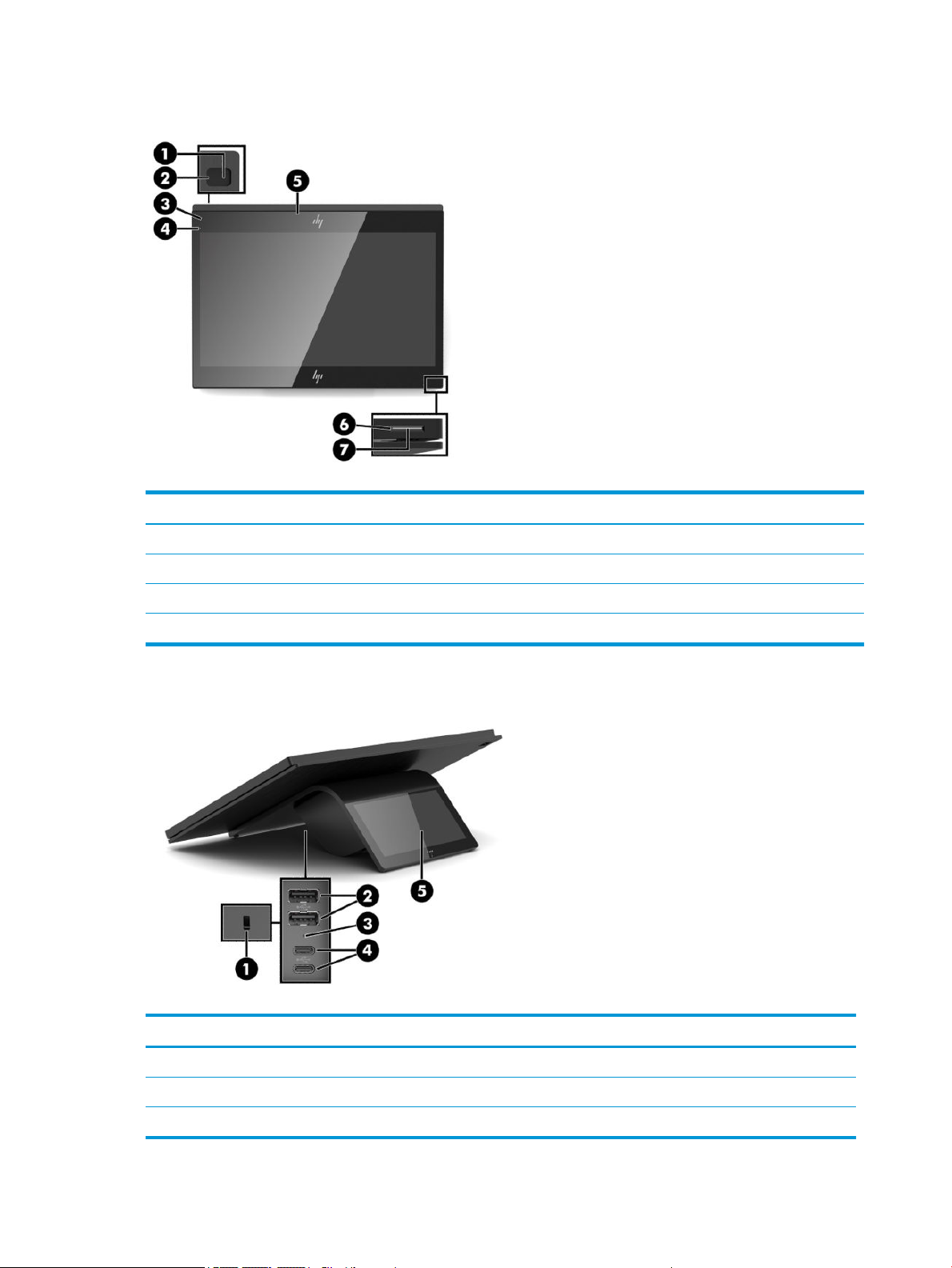
Bezel components
Table 1-1 Bezel components
Bezel components
(1) Rear-facing camera (5) MSR
(2) Rear-facing camera light (6) Power button
(3) Magnetic stripe reader (MSR) light (7) Power button light
(4) Front-facing camera
Rear components
Table
1-2 Rear components
Rear components
(1) Security cable slot (4) USB Type-C ports (2)
(2) USB Type-A ports (2) (5) Customer-facing display (optional)
(3) Volume button
2 Chapter 1 Product overview
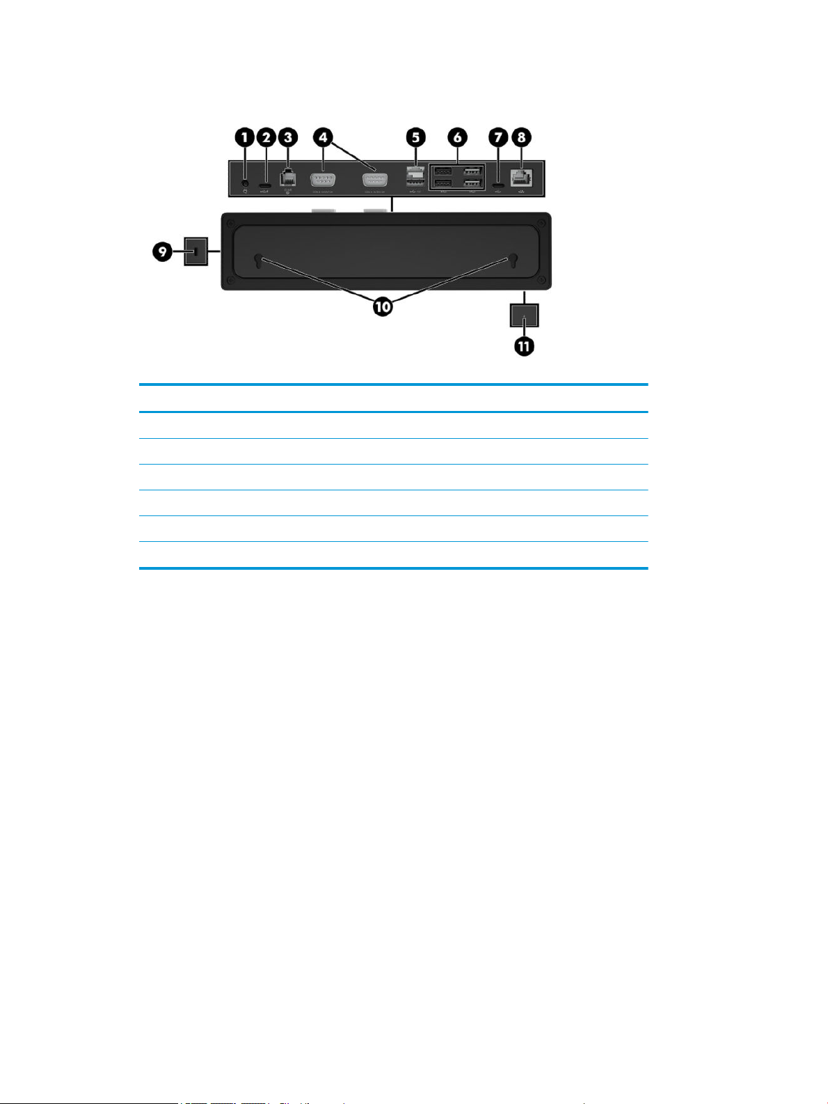
Optional hub components
Table 1-3 Hub components
Hub components
(1) Power connector (7) USB Type-C port
(2) USB Type-C powered port (8) RJ-45 (network) jack
(3) Cash drawer jack (9) Security cable slot
(4) Powered serial ports (10) Wall mount keyholes
(5) Powered USB 12 V port (11) Power light
(6) USB ports (4)
Optional hub components 3
Conguring the hub’s powered serial ports
The serial ports can be congured as standard (non-powered) serial ports or powered serial ports. Some
devices use a powered serial port. If the serial port is congured as a powered port, devices that support a
powered serial interface do not require an external power source.
IMPORTANT: The computer must be turned o before you connect or disconnect serial port devices.
NOTE: The hub ships with all serial ports congured in standard, non-powered serial mode (0 volts).
There are three voltage settings for each serial port:
● 0 volts
● 5 volts
● 12 volts
To change the voltage setting for each powered serial port:
1. In the software included with the product, select Settings.
2. Select Connected devices and then select Powered Serial Port Voltage.
3. Select the appropriate voltage for the connected device.
IMPORTANT: To reduce the risk of damage to a connected device, make sure that you select the correct
serial port voltage.
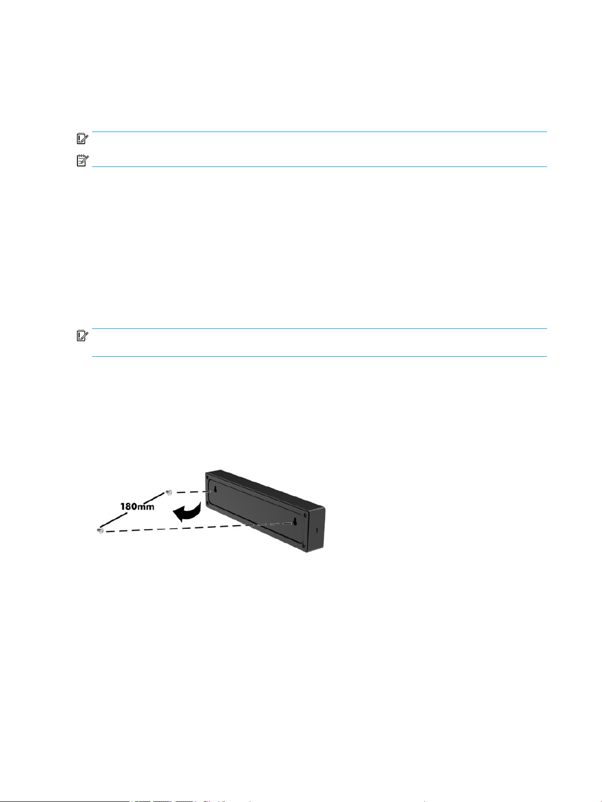
Mounting the hub
The hub can be attached to a wall or other surface using the keyholes on the back of the hub.
The suspension height for the hub should not exceed 2 meters. The spacing for the two screws embedded in
the wall is 180 mm. The screw thread size should be M3, and the screw length should be no less than 6 mm
with a diameter of 3 mm.
4 Chapter 1 Product overview
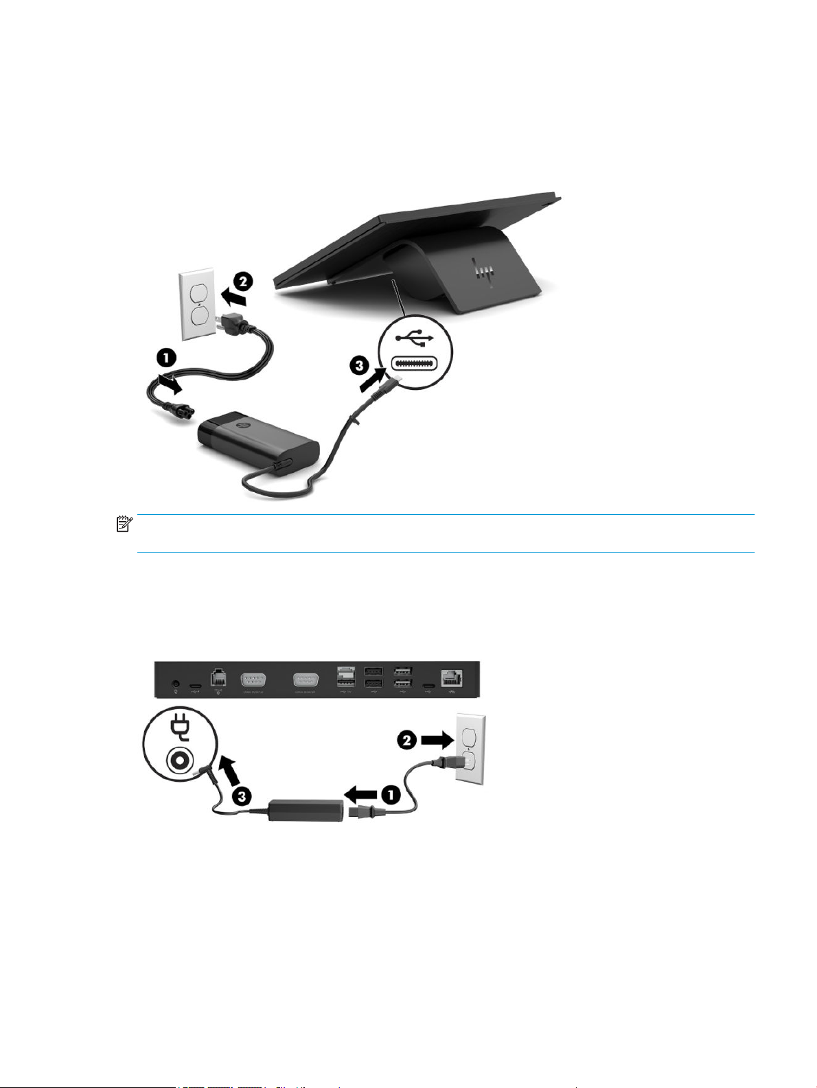
Connecting power to the computer
To connect an AC adapter to the computer, connect one end of the power cord to the AC adapter (1) and the
other end to a grounded AC outlet (2), and then connect the AC adapter to one of the USB Type-C ports on the
computer (3).
NOTE: If the computer is connected to the optional hub, you can connect a USB Type-C cable to the hub’s
USB Type-C powered port instead of using the AC adapter to power the computer.
Connecting power to the hub
To connect an AC adapter to the hub, connect one end of the power cord to the AC adapter (1) and the other
end to a grounded AC outlet (2), and then connect the AC adapter to the power connector on the hub (3).
Connecting power to the computer 5

Connecting the optional hub to the computer
Use a USB Type-C cable to connect the computer and the USB Type-C powered port on the hub.
NOTE: The computer does not need to be connected to an AC adapter when connected to the USB Type-C
powered port on the hub.
Locating the computer power button
The power button is located on the bottom right edge of the bezel.
NOTE: The power button light is white when the computer is on. The power button light is o when the
computer is o. The power button light blinks when the computer is in the Sleep state.
6 Chapter 1 Product overview

Adjusting the tilt
You can tilt the computer so that it is facing the cashier or the customer. The image on the screen
automatically rotates to match the position of the computer. The computer can be stabilized at various angles
to adjust for glare and counter height.
Computer serial number location
Each computer has a unique serial number and a product ID number that are located on the exterior of the
unit. Keep these numbers available for use when contacting support for assistance.
Adjusting the tilt 7

Hub serial number location
Each hub has a unique serial number and a product ID number that are located on the exterior of the hub.
Keep these numbers available for use when contacting support for assistance.
Contacting support
To resolve a hardware or software problem, go to http://www.hp.com/support. Use this site to get more
information about your product, including links to discussion forums and instructions on troubleshooting. You
can also nd information about how to contact HP and open a support case.
8 Chapter 1 Product overview

2 Using and updating the computer
Turning on the computer
▲ Press and hold the power key for three seconds. The startup logo should display in about two seconds.
Turning o the computer
1. Press the power key.
2. Select Shutdown.
Installing HP updates
1. Open the HP Device Hub application.
2. Select Update to the latest OS.
3. Select the update.
Updating the rmware
1. Open the HP Device Hub application.
2. Select HP Device Firmware Update.
3. Select the available update and follow on-screen instructions.
Performing a soft reset
▲ Press and hold the power button for about 10 seconds to reset the computer.
TIP: The only function of the RTC battery is to keep the current time.
Android devices do not include a BIOS or CMOS.
Computer power button light behavior
The computer power button light functions as follows:
● On (S0): Computer is on.
● O (S5): Computer is o.
● Blinking (fades in for three seconds, fades out for three seconds): Computer is in the Sleep (S3) state.
For more information about the computer power button light location, see Bezel components on page 2.
Turning on the computer 9

Hub power light behavior
When connected to the computer, the hub power light functions as follows:
● On (S0): Computer light is on. Hub power light is on
● O (S5): Computer is o. Hub power light is o.
● Blinking (fades in for three seconds, fades out for three seconds): Computer and hub are in the Sleep
(S3) state.
When not connected to the computer, the hub power light functions as follows:
● On for 15 seconds, then blinking (fades in for three seconds, fades out for three seconds): Computer
removed.
● On for 15 seconds, then blinking (fades in for three seconds, fades out for three seconds): AC adapter
connected, computer not connected.
Hub power light error blinking functions as follows:
● Blinking (one for one second, o or one second): Insucient AC adapter (less than 120 W) connected.
● Blinking (one for one second, o or one second): Overpowered AC adapter connected.
For more information about the computer power button light location, see Bezel components on page 2.
For more information about the hub power light location, see Optional hub components on page 3.
Over-the-air (OTA) update
Preparing the USB ash drive
Performing an OTA update requires a 2 GB or larger USB ash drive. You must format the drive using the
FAT32 le system.
To prepare the USB ash drive:
1. Insert the USB ash drive containing the OTA package into a Windows® computer.
2. Open File Explorer.
3. Right-click the USB drive in the navigation panel.
4. Select Format.
5. Under Capacity verify that the USB ash drive capacity is at least 2 GB.
6. Under File system select FAT32.
7. Copy the OTA package to the root of the USB drive.
Performing the OTA update from the Additional System Updates menu
1. Insert the USB ash drive containing the OTA package into the Android device.
2. Conrm that the USB drive is recognized in the Files app on the Android device.
3. Tap Settings, and then tap Additional System Updates.
4. Tap the upgrade package, and then tap Install.
10 Chapter 2 Using and updating the computer

5. Tap Update to start the update process. Once the update is complete, the computer restarts.
6. Go to the About device menu to check the build number to verify that the update was successful.
Performing the OTA update from Recovery
1. Enter the Recovery menu:
Method 1 (from the Android operating system)
a. Tap Settings, and then tap Additional System Updates.
b. Insert the USB ash drive into the Android device.
Tap the Options button , and then tap Reboot in recovery.
c.
Method 2 (from restart)
a. Power o the Android device.
b. Use a pin or similar thin tool to hold the volume button, located between the USB ports on the back
of the device.
c. While holding the volume button, press the power button to turn the device on.
2. Move the cursor to Apply update from SD Card, and then press the power button to select.
3. Select the OTA update package, and then press the power button to start the update.
After the update has completed, the Android Recovery screen displays.
4. Select Reboot system now to restart the computer.
5. Go to the About device menu and check the build number to verify that the update was successful.
Operating system recovery using Fastboot ash device
Entering Fastboot mode
If you can start the operating system:
1. Tap Settings, tap About device, and then tap Additional System Updates.
2. Tap the Options button , and then tap Reboot in recovery.
3. In the Recovery Menu, tap Reboot to bootloader to enter Fastboot mode.
If the operating system is corrupt:
Operating system recovery using Fastboot ash device 11

1. Start the device using the power button.
2. Press and release the volume button, located between the USB ports on the back of the device.
3. Use the volume button to navigate to Fastboot, and then use the power button to select.
Downloading the Android Bootloader driver
1. Using the rst (top) USB Type-C port, connect the device to a Windows computer.
2. Open Windows Device Manager.
3. Find the Android device. It may be listed under Other devices.
Conrm that Android Bootloader is displayed under the Android device. If Android Bootloader is not
displayed:
a. Download Android Bootloader from https://developer.android.com/studio/run/win-usb.
b. In Device Manager, right click the Android device. It may be labeled ‘Android’.
c. Select Update Driver.
d. Select Browse my computer for driver software.
e. Select Let me pick from a list.
f. Select Android Device, and then click Next.
g. Select Have Disk.
h. Browse to the downloaded ABI les, and then select OK.
4. Unzip and open the Android OTA image les.
5. Open ash-all.bat.
After the ash has completed, the device automatically starts the installed operating system.
12 Chapter 2 Using and updating the computer

3 Operating guidelines, routine care, and
shipping preparation
Operating guidelines and routine care
Follow the guidelines below to properly set up and care for the computer:
● Keep the computer away from excessive moisture, direct sunlight, and extremes of heat and cold.
● Never operate the computer with any access panels removed.
● Do not stack computers on top of each other or place them so near each other that they are subject to
each other’s recirculated or preheated air.
● If the computer is to be operated within a separate enclosure, intake and exhaust ventilation must be
provided on the enclosure, and the same operating guidelines listed above still apply.
● Keep liquids away from the computer and hub.
● Never cover the vents on the computer or hub with any type of material.
● Install or enable power management functions of the operating system or other software, including
Sleep states.
● Turn o the computer and wipe the exterior with a soft, damp cloth as necessary. Using cleaning
products may discolor or damage the nish.
● Wipe the exterior with a soft, damp cloth as necessary. Using cleaning products may discolor or
damage the nish.
NOTE: For more information on your retail system care and maintenance, go to http://www.hp.com/
support. Then type ‘Retail Point of Sales Systems - Routine Care and Maintenance’ and click Search all
support.
Touch screen maintenance
Keep your touch screen clean. The touch screen requires very little maintenance. HP recommends that you
periodically clean the glass surface. Be sure to turn o your display before cleaning. Typically, an isopropyl
alcohol and water solution ratio of 50:50 is the best cleaning agent for your touch screen. It is important to
avoid using any caustic chemicals on the touch screen. Do not use any vinegar-based solutions.
Apply the cleaner with a soft, lint-free cloth. Avoid using gritty cloths. Always dampen the cloth and then
clean the sensor. Be sure to spray the cleaning liquid onto the cloth, not the sensor, so that drips do not seep
inside the display or stain the bezel.
MSR maintenance
To clean the MSR (magnetic stripe reader), swipe a standard cleaning card through the MSR a couple of times.
You can order a standard cleaning card online. You can also put a thin oil-free cloth around a credit card.
Operating guidelines and routine care 13

Cleaning the barcode scanner
Exterior surfaces and scan windows exposed to spills, smudges, or debris require periodic cleaning to ensure
best performance during scanning. Use a soft, dry cloth to clean the product. If the product is very soiled,
clean it with a soft cloth moistened with a diluted non-aggressive cleaning solution or diluted ethyl alcohol.
IMPORTANT: Do not use abrasive or aggressive cleansing agents or abrasive pads to clean scan windows or
plastics. Do not spray or pour liquids directly onto the unit.
Cleaning the printer
Because of the way the printer sits while in use, paper and other debris from the knife can build up. HP
recommends that you keep the printer in working order by periodically cleaning the debris from the printer.
To clean the printer, open the cover, remove the paper roll, and then use a can of compressed air to blow out
the debris from the bottom plate where it accumulates.
Cleaning I/O ports
The computer has a series of ports. Dust and debris can collect in these ports, which can reduce connectivity
and performance. Use a battery-powered vacuum to remove any debris that has accumulated in and around
these ports.
Updating drivers and rmware
HP recommends that you regularly download and install the latest drivers and rmware updates to help
enhance system performance, resolve known issues, and avoid replacing parts unnecessarily.
To download and install the latest drivers and updates for your specic Retail Point of Sale model, go to
http://www.hp.com/support, and follow the instructions to nd your product. Then select Software, Drivers,
and Firmware.
Shipping preparation
Follow these suggestions when preparing to ship the computer:
1. Back up the hard drive les. Be sure that the backup media is not exposed to electrical or magnetic
impulses while stored or in transit.
NOTE: The hard drive locks automatically when the computer power is turned o.
2. Remove and store all removable media.
3. Turn o the computer and external devices.
4. Disconnect the power cord from the AC outlet, and then from the computer.
5. Disconnect the computer components and external devices from their power sources, and then from the
computer.
6. Pack the computer components and external devices in their original packing boxes or similar packaging
with sucient packing material to protect them.
14 Chapter 3 Operating guidelines, routine care, and shipping preparation

Electrostatic discharge information
A sudden discharge of static electricity from your nger or other conductor can destroy static-sensitive
devices or microcircuitry. Often the spark is neither felt nor heard, but damage occurs. An electronic device
exposed to electrostatic discharge (ESD) may not appear to be aected at all and can work perfectly
throughout a normal cycle. The device may function normally for a while, but it has been degraded in the
internal layers, reducing its life expectancy.
Networks built into many integrated circuits provide some protection, but in many cases, the discharge
contains enough power to alter device parameters or melt silicon junctions.
IMPORTANT: To prevent damage to the device when you are removing or installing internal components,
observe these precautions:
Keep components in their electrostatic-safe containers until you are ready to install them.
Before touching an electronic component, discharge static electricity by using the guidelines described in this
section.
Avoid touching pins, leads, and circuitry. Handle electronic components as little as possible.
If you remove a component, place it in an electrostatic-safe container.
Generating static electricity
Note the following:
● Dierent activities generate dierent amounts of static electricity.
● Static electricity increases as humidity decreases.
Table
3-1 Static electricity occurrence based on activity and humidity
Relative humidity
Event 55% 40% 10%
Walking across carpet
Walking across vinyl oor
Motions of bench worker
Removing DIPs from plastic tube
Removing DIPs from vinyl tray
Removing DIPs from Styrofoam
Removing bubble pack from PCB
Packing PCBs in foam-lined box
Electronic components are multi-packaged inside plastic tubes, trays, or Styrofoam.
NOTE: As little as 700 volts can degrade a product.
Preventing electrostatic damage to equipment
7,500 V
3,000 V
400 V
400 V
2,000 V
3,500 V
7,000 V
5,000 V
15,000 V
5,000 V
800 V
700 V
4,000 V
5,000 V
20,000 V
11,000 V
35,000 V
12,000 V
6,000 V
2,000 V
11,500 V
14,500 V
26,500 V
21,000 V
Many electronic components are sensitive to ESD. Circuitry design and structure determine the degree of
sensitivity. The following packaging and grounding precautions are necessary to prevent static electricity
damage to electronic components.
Electrostatic discharge information 15

● To avoid hand contact, transport products in static-safe containers such as tubes, bags, or boxes.
● Protect all electrostatic parts and assemblies with conductive or approved containers or packaging.
● Keep electrostatic-sensitive parts in their containers until they arrive at static-free stations.
● Place items on a grounded surface before removing them from their container.
● Always be properly grounded when touching a sensitive component or assembly.
● Avoid contact with pins, leads, or circuitry.
● Place reusable electrostatic-sensitive parts from assemblies in protective packaging or conductive
foam.
Personal grounding methods and equipment
Use the following equipment to prevent static electricity damage to electronic components:
● Wrist straps are exible straps with a maximum of one-megohm ± 10% resistance in the ground cords.
To provide proper ground, a strap must be worn snug against bare skin. The ground cord must be
connected and t snugly into the banana plug connector on the grounding mat or workstation.
● Heel straps/Toe straps/Boot straps can be used at standing workstations and are compatible with
most types of shoes or boots. On conductive oors or dissipative oor mats, use them on both feet with
a maximum of one-megohm ± 10% resistance between the operator and ground.
Table
3-2 Static shielding protection levels
Static shielding protection levels
Method Voltage
Antistatic plastic
Carbon-loaded plastic
Metallized laminate
Grounding the work area
To prevent static damage at the work area, use the following precautions:
● Cover the work surface with approved static-dissipative material. Provide a wrist strap connected to the
work surface and properly grounded tools and equipment.
● Use static-dissipative mats, foot straps, or air ionizers to give added protection.
● Handle electrostatic sensitive components, parts, and assemblies by the case or PCB laminate. Handle
them only at static-free work areas.
● Turn o power and input signals before inserting and removing connectors or test equipment.
● Use xtures made of static-safe materials when xtures must directly contact dissipative surfaces.
● Keep work area free of nonconductive materials such as ordinary plastic assembly aids and Styrofoam.
● Use eld service tools, such as cutters, screwdrivers, and vacuums, that are conductive.
1,500
7,500
15,000
16 Chapter 3 Operating guidelines, routine care, and shipping preparation

Recommended materials and equipment
Materials and equipment that are recommended for use in preventing static electricity include:
● Antistatic tape
● Antistatic smocks, aprons, or sleeve protectors
● Conductive bins and other assembly or soldering aids
● Conductive foam
●
Conductive tabletop workstations with ground cord of one-megohm +/- 10% resistance
● Static-dissipative table or oor mats with hard tie to ground
● Field service kits
● Static awareness labels
● Wrist straps and footwear straps providing one-megohm +/- 10% resistance
● Material handling packages
● Conductive plastic bags
● Conductive plastic tubes
● Conductive tote boxes
● Opaque shielding bags
● Transparent metallized shielding bags
● Transparent shielding tubes
Electrostatic discharge information 17

A Power cord set requirements
The power supplies on some computers have external power switches. The voltage select switch feature on
the computer permits it to operate from any line voltage between 100-120 or 220-240 volts AC. Power
supplies on those computers that do not have external power switches are equipped with internal switches
that sense the incoming voltage and automatically switch to the proper voltage.
The power cord set received with the computer meets the requirements for use in the country where you
purchased the equipment.
Power cord sets for use in other countries must meet the requirements of the country where you use the
computer.
General requirements
The requirements listed below are applicable to all countries:
1. The power cord must be approved by an acceptable accredited agency responsible for evaluation in the
country where the power cord set will be installed.
2. The power cord set must have a minimum current capacity of 10A (7A Japan only) and a nominal voltage
rating of 125 or 250 volts AC, as required by each country’s power system.
3. The diameter of the wire must be a minimum of 0.75 mm2 or 18AWG, and the length of the cord must be
between 1.8 m (6 feet) and 3.6 m (12 feet).
The power cord should be routed so that it is not likely to be walked on or pinched by items placed upon it or
against it. Particular attention should be paid to the plug, electrical outlet, and the point where the cord exits
from the product.
WARNING! Do not operate this product with a damaged power cord set. If the power cord set is damaged in
any manner, replace it immediately.
Japanese power cord requirements
For use in Japan, use only the power cord received with this product.
CAUTION: Do not use the power cord received with this product on any other products.
18 Appendix A Power cord set requirements

Country-specic requirements
Additional requirements specic to a country are shown in parentheses and explained below.
Table A-1 Power cord country-specic requirements
Country Accrediting Agency Country Accrediting Agency
Australia (1)
Austria (1)
Belgium (1)
Canada (2)
Denmark (1)
Finland (1)
France (1)
Germany (1)
1. The exible cord must be Type HO5VV-F, 3-conductor, 0.75mm2 conductor size. Power cord set ttings (appliance coupler and
wall plug) must bear the certication mark of the agency responsible for evaluation in the country where it will be used.
2. The exible cord must be Type SVT or equivalent, No. 18 AWG, 3-conductor. The wall plug must be a two-pole grounding type
with a NEMA 5-15P (15A, 125V) or NEMA 6-15P (15A, 250V) conguration.
3. Appliance coupler, exible cord, and wall plug must bear a “T” mark and registration number in accordance with the Japanese
Dentori Law. Flexible cord must be Type VCT or VCTF, 3-conductor, 0.75 mm2 conductor size. Wall plug must be a two-pole
grounding type with a Japanese Industrial Standard C8303 (7A, 125V) conguration.
EANSW
OVE
CEBC
CSA
DEMKO
SETI
UTE
VDE
Italy (1)
Japan (3)
Norway (1)
Sweden (1)
Switzerland (1)
United Kingdom (1)
United States (2)
IMQ
METI
NEMKO
SEMKO
SEV
BSI
UL
Country-specic requirements 19

B Statement of memory volatility
IMPORTANT: Information in this chapter may not apply to all models with the Android operating system.
The purpose of this chapter is to provide general information regarding nonvolatile memory in HP Business
computers. This chapter also provides general instructions for restoring nonvolatile memory that can contain
personal data after the system has been powered
HP Business computer products that use Intel®-based or AMD®-based system boards contain volatile DDR
memory. The amount of nonvolatile memory present in the system depends upon the system conguration.
Intel-based and AMD-based system boards contain nonvolatile memory subcomponents as originally shipped
from HP, assuming that no subsequent modications have been made to the system and assuming that no
applications, features, or functionality have been added to or installed on the system.
Following system shutdown and removal of all power sources from an HP Business computer system,
personal data can remain on volatile system memory (DIMMs) for a nite period of time and will also remain
in nonvolatile memory. Use the steps below to remove personal data from the computer, including the
nonvolatile memory found in Intel-based and AMD-based system boards.
NOTE: If your tablet has a keyboard base, connect to the keyboard base before beginning steps in this
chapter.
o and the hard drive has been removed.
20 Appendix B Statement of memory volatility

Nonvolatile memory usage
Table B-1 Troubleshooting steps for nonvolatile memory usage
Nonvolatile
Memory Type Amount (Size)
Real Time Clock
(RTC) battery
backed-up CMOS
conguration
memory
Controller (NIC)
EEPROM
DIMM Serial
Presence Detect
(SPD)
conguration data
Bluetooth ash
(select products
only)
256 bytes No Yes Stores system
64 KB (not
customer
accessible)
256 bytes per
memory
module, 128
bytes
programmable
(not customer
accessible)
2 Mb No Yes Stores
Does this
memory
store
customer
data?
No Yes Stores NIC
No Yes Stores memory
Does this
memory
retain data
when power
is removed?
What is the
purpose of this
memory?
date and time
and noncritical
data.
conguration
and NIC
rmware.
module
information.
Bluetooth
conguration
and rmware.
How is data input into this
memory?
RTC battery backed-up CMOS
is programmed using
Computer Setup (BIOS), or by
changing the Microsoft®
Windows date & time.
NIC EEPROM is programmed
using a utility from the NIC
vendor that can be run from
DOS.
DIMM SPD is programmed by
the memory vendor.
Bluetooth ash is
programmed at the factory.
Tools for writing data to this
memory are not publicly
available but can be obtained
from the silicon vendor.
How is this memory
write-protected?
This memory is not writeprotected.
A utility must be used to
write data to this memory
and is available from the
NIC vendor. Writing data
to this ROM in an
inappropriate manner will
render the NIC nonfunctional.
Data cannot be written to
this memory when the
module is installed in a
computer. The specic
write-protection method
varies by memory vendor.
A utility must be used for
writing data to this
memory and is made
available through newer
versions of the driver
whenever the ash
requires an upgrade.
802.11 WLAN
EEPROM
Webcam (select
products only)
Fingerprint reader
(select products
only)
4 Kb to 8 Kb No Yes Stores
conguration
and calibration
data.
64 Kb No Yes Stores webcam
conguration
and rmware.
512 KB ash Yes Yes Stores
ngerprint
templates.
802.11 WLAN EEPROM is
programmed at the factory.
Tools for writing data to this
memory are not made public.
Webcam memory is
programmed using a utility
from the device
manufacturer that can be run
from Windows.
Fingerprint reader memory is
programmed by user
enrollment in HP
ProtectTools Security
Manager.
Nonvolatile memory usage 21
A utility must be used for
writing data to this
memory and is typically
not made available to the
public unless a rmware
upgrade is necessary to
address a unique issue.
A utility must be used for
writing data to this
memory and is typically
not made available to the
public unless a rmware
upgrade is necessary to
address a unique issue.
Only a digitally signed
application can make the
call to write to the ash.

C Specications
Computer specications
Table C-1 Computer specications
Metric U.S.
Dimensions
Length 260 mm 10.24 in
Width 334 mm 13.15 in
Height 127 mm 5.00 in
Temperature
Operating 0°C to 35°C 32°F to 95°F
Nonoperating ‑30°C to 65°C ‑22°F to 149°F
Relative humidity (operating) 10% to 90%
Maximum altitude (unpressurized)
Operating 0 m to 3,048 m 0 ft to 10,000 ft
Nonoperating 0 m to 9,144 m 0 ft to 30,000 ft
Power supply 45 W, 87.8% ecient at 15 V, active PFC
AC voltage range 90 V – 265 VAC
Rated line frequency 50~60 HZ
Operating line frequency range 47~63 HZ
Rated input current 1.4A RMS @ 90 VAC & max load, 2.2A RMS @ 90 VAC & max load
Magnetic Stripe Reader Integrated MSR reader, triple-track head, ISO 7811/7812/7813 Compliant,
encryption capable
Front Camera Integrated front camera (5M, FF)
Barcode Reader (back camera) Integrated back camera (5M, FF) with ash LED
Acoustic functions
1 microphone integrated
1 speaker integrated, 1 W, embedded codec
I/O Ports
USB-C port x2 Supports PD (power and data), if one USB-C port becomes PD power sink (15 V/3
A), another port can be PD source (5 V/0.9 A, 5 V/3 A, 9 V/3 A)
USB 2.0 port x2 USB 2.0 (5 V/0.5 A)
22 Appendix C Specications

Main display specications
Table C-2 Main display specications
1
Metric U.S.
Active diagonal size 35.6 cm 14.0 in
Operating temperature range 0 to 50°C 32°F to 122°F
Touch technology Projected capacitive touch screen
Resolution 1920 × 1080
Aspect ratio 16:9
Maximum color 262K
Brightness
Contrast ratio
Typical 220 nits
Typical 700:1
2
2
Pixel pitch 161 μm × 161 μm
Viewing angle Horizontal 85°, Vertical 85°
Response rate 30 ms
Backlight LED
Surface treatment Anti glare
1
All specications represent the typical specications provided by HP's component manufacturers; actual performance may vary
either higher or lower.
2
Nits is the measure of the typical brightness of the panel as specied, prior to anti-glare coating
Main display specications 23

Customer-facing display specications
Table C-3 Customer-facing display specications
Metric U.S.
Active diagonal size 14.0 cm 5.5 in
Operating temperature range 0 to 50°C 32°F to 122°F
Display technology AMOLED
Resolution 1920 × 1080
Aspect ratio 16:9
Maximum color 16.7M
Brightness
Contrast ratio Minimum 100K:1
Pixel pitch 63.25 μm × 63.25 μm
Viewing angle All view
Response rate 1 ms
1
All specications represent the typical specications provided by HP's component manufacturers; actual performance may vary
either higher or lower.
2
Nits is the measure of the typical brightness of the panel as specied, prior to anti-glare coating
1
Typical 420 nits
2
24 Appendix C Specications

Index
A
Android Bootloader driver 12
B
barcode scanner
cleaning 14
C
cautions
electrostatic discharge 15
computer components
bezel 2
rear 2
computer power button light 9
computer specications 22
connecting power to the computer
5
connecting power to the hub 5
connecting the hub to the
computer 6
country power cord set
requirements 19
D
display specications 23, 24
drivers and rmware, updating 14
E
electrostatic discharge (ESD) 15
preventing damage 15
F
Fastboot mode 11
features 1
G
grounding methods 16
H
HP software, updating 9
hub components 3
hub power light 10
hub serial ports 4
hub wall mount 4
I
installing HP updates 9
M
memory
nonvolatile 20
volatile 20
MSR maintenance 13
N
nonvolatile memory 20
O
operating guidelines 13
operating system recovery 11
OTA update from Additional System
Updates menu 10
OTA update from Recovery 11
P
performing a soft reset 9
ports, cleaning 14
power button 6
power cord set requirements
country specic 19
powering o the computer 9
powering on the computer 9
printer
cleaning 14
R
recovery 11
removing personal data from volatile
system memory 20
reset 9
S
serial number
computer 7
hub 8
shipping preparation 14
soft reset 9
software, updating 9
specications
computer 22
customer-facing display 24
main display 23
static electricity 15
system memory, removing personal
data from volatile 20
T
technical support 8
tilt adjustment 7
touch screen maintenance 13
U
updating the computer 9
updating the rmware 9
USB ash drive 10
using the computer 9
Index 25
 Loading...