

Page 1

HP 5642 Rack
User Guide
November 2004 (First Edition)
Part Number 366309-001
Page 2

© Copyright 2004 Hewlett-Packard Development Company, L.P.
The information contained herein is subject to change without notice. The only warranties for HP products
and services are set forth in the express warranty statements accompanying such products and services.
Nothing herein should be construed as constituting an additional warranty. HP shall not be liable for
technical or editorial errors or omissions contained herein.
HP 5642 Rack User Guide
November 2004 (First Edition)
Part Number 366309-001
Audience Assumptions
This document is for the person who installs racks and rack products. This procedure is performed only by
trained personnel. HP assumes you are qualified in performing installations and trained in recognizing
hazards in rack products.
Page 3

3
Contents
Overview 5
HP 5642 Rack ......................................................................................................................................5
Ordering Rack Options ........................................................................................................................5
Installation Overview...........................................................................................................................6
Installation Service...............................................................................................................................7
Assembling the HP 5642 Rack 9
Maximum Load Capacity.....................................................................................................................9
Rack Caution........................................................................................................................................9
Kit Contents .......................................................................................................................................10
Required Tools................................................................................................................................... 14
Assembling the HP 5642 Rack ..........................................................................................................14
Configuration Factors 31
Maximum Load Capacity...................................................................................................................31
Rack Caution......................................................................................................................................31
Configuration Factors ........................................................................................................................32
Rack Configuration Software.............................................................................................................32
Custom Builder Online Modes of Operation .....................................................................................32
Component Placement .......................................................................................................................33
Additional Considerations..................................................................................................................33
Optimum Environment ......................................................................................................................35
Space Requirements................................................................................................................35
Power Requirements...............................................................................................................35
Temperature Requirements.....................................................................................................36
Airflow Requirements ............................................................................................................36
Multiple Racks................................................................................................................................... 37
Installing Components 39
General Guidelines.............................................................................................................................39
Preparing the Rack for Component Installation.................................................................................41
Checking the Hardware ..........................................................................................................41
Removing the Side Panels ......................................................................................................41
Removing the Rack Doors...................................................................................................... 43
Installing Components .......................................................................................................................44
Using the Rack Template........................................................................................................45
Installing the Cage Nuts..........................................................................................................46
Page 4

4 HP 5642 Rack User Guide
Specifications 49
HP 5642 Rack Specifications............................................................................................................. 49
Electrostatic Discharge 51
Preventing Electrostatic Discharge ....................................................................................................51
Grounding Methods to Prevent Electrostatic Discharge.................................................................... 52
Technical Support 53
HP Contact Information.....................................................................................................................53
Before You Contact HP .....................................................................................................................53
Acronyms and Abbreviations 55
Index 57
Page 5

5
Overview
In This Section
HP 5642 Rack.................................................................................................................................5
Ordering Rack Options...................................................................................................................5
Installation Overview .....................................................................................................................6
Installation Service .........................................................................................................................7
HP 5642 Rack
The HP 5642 Racks offer the following features:
• Simple installation
• Split rear doors
• Split side panels
• Cable access area below rear door
Ordering Rack Options
In addition to the standard racks, HP also provides rack options to complement or
complete your rack solution. The following list is only a sampling of the many
rack option kits available. For information about ordering rack option kits visit
the HP website (http://www.hp.com/products/rackoptions
HP authorized reseller or service provider.
Rack Option Description
Stabilizer Rack Option Kit Increases the stability of free-standing
Baying Rack Option Kit Joins multiple racks of the same series,
Monitor/Utility Rack Option Kit Holds a monitor or other rack
) or contact the nearest
racks, or for use with modified side feet
height, and depth
component
Page 6

6 HP 5642 Rack User Guide
Rack Option Description
Server Console Switch Programmable switch panel with
1U Keyboard Drawer Option Kit Holds and conceals a keyboard
connection hardware used to switch a
keyboard, monitor, and mouse among
multiple servers
100 Kilo Sliding Shelf Rack Option
Kit
TFT5600 RKM Rack-mountable 1U keyboard and flat-
Blanking Panel Rack Option Kit Covers open areas of the rack to better
TFT7210R Flat Panel Monitor
Rackmount
Installation Overview
HP recommends the following sequence of events for the most safe and efficient
installation of your rack and components.
1. Install the Customer Builder software from the HP website
(http://h30099.www3.hp.com/configurator/eco-cb/custombuilder.asp
the Custom Builder, plan the rack component location and installation
sequence.
2. Select a location to set up your rack. This should be the permanent site for
your rack.
Allows easy access to various rack
components
panel monitor on a drawer with room in
the rear to add a switchbox
control airflow
Rack-mountable 1U flat-panel monitor
with room in the rear to add a
switchbox
). Using
3. Assemble the rack. For your convenience, rack contents are packaged to
follow the installation steps.
4. Stabilize the rack by adjusting the leveling feet.
5. Bay multiple racks together (recommended if more than one rack is being
used side by side).
6. Install products, such as PDUs or console switches, in sidewall or 0U
locations.
Page 7

Overview 7
7. Install products, such as UPS units, starting from the bottom of the rack.
8. Install the appropriate support rails and tray for the first rack-mountable
component.
9. Install the first individual component.
10. Attach a cable management arm if required.
11. Attach the appropriate cables and power cords to the component, being sure
to adhere to all cautions and warnings.
12. Install the remaining components in the appropriate sequence.
13. Reinstall any doors and side panels.
14. Power up and configure the systems.
Installation Service
In the US, HP can make arrangements to have your rack system installed by
qualified guaranteed service providers. This installation service covers the entire
hardware installation sequence, from unpacking the components to routing
cabling and running a test of the system. For more information, visit the HP
website (http://www.hp.com/products/racks
).
Page 8

Page 9

9
Assembling the HP 5642 Rack
In This Section
Maximum Load Capacity ...............................................................................................................9
Rack Caution ..................................................................................................................................9
Kit Contents..................................................................................................................................10
Required Tools .............................................................................................................................14
Assembling the HP 5642 Rack.....................................................................................................14
Maximum Load Capacity
Rack Caution
CAUTION: Do not exceed the maximum load capacity, 680.38
kg (1,500 lb), for this rack.
CAUTION: To reduce the risk of personal injury or damage to
the equipment, be sure that:
• This procedure is performed after you have read these instructions
completely.
• You select a location to set up your rack. This location should be as
close as possible to the permanent site for your rack.
• The leveling feet are extended to the floor to stabilize the rack.
• Two or more people are available to lift and stabilize the product
pieces during assembly.
• After you install the side panels, they are secured to the rack frame
before releasing them.
• The maximum load capacity for this rack is 680.38 kg (1,500 lb).
Page 10
10 HP 5642 Rack User Guide
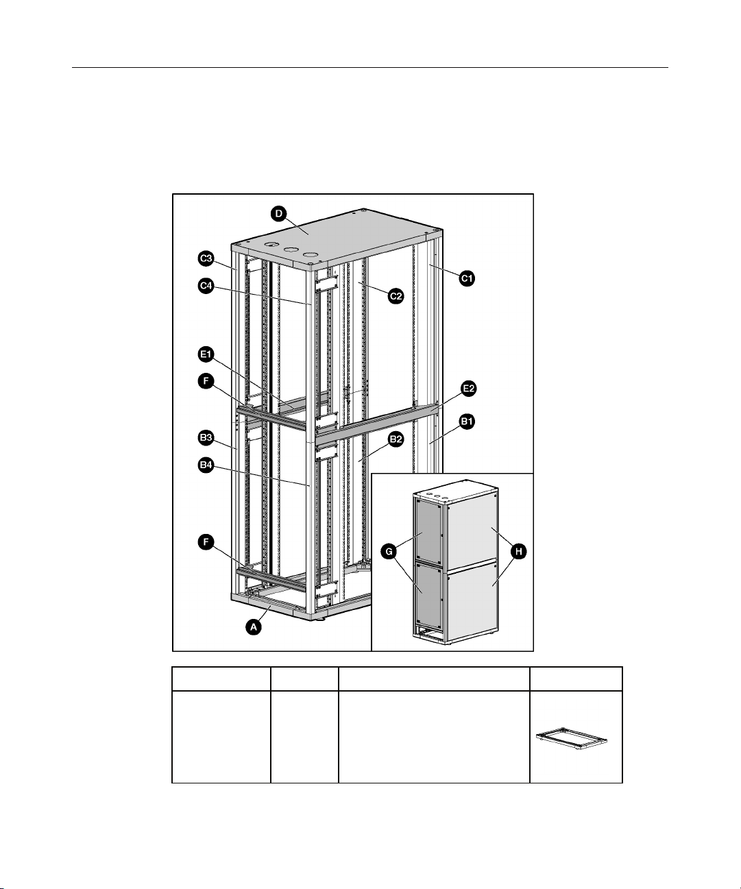
Kit Contents
If any of the following items are missing or damaged, contact your HP
authorized reseller. The following hardware pieces are included in this kit:
Identification Quantity Piece Description Picture
A
1 piece Rack base (with leveling feet
already attached)
Page 11
Assembling the HP 5642 Rack 11
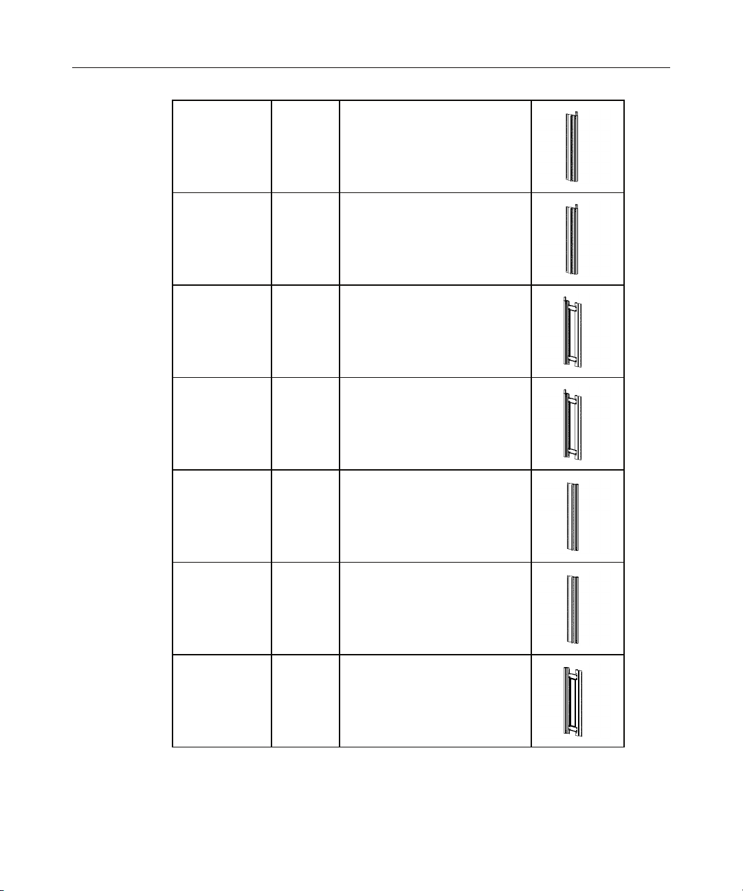
B1
B2
B3
B4
C1
1 piece Lower left front vertical frame
piece
1 piece Lower right front vertical frame
piece
1 piece Lower left rear vertical frame
piece (with Retma rail attached)
1 piece Lower right rear vertical frame
piece (with Retma rail attached)
1 piece Upper left front vertical frame
piece
C2
1 piece Upper right front vertical frame
piece
C3
1 piece Upper left rear vertical frame
piece (with Retma rail attached)
Page 12
12 HP 5642 Rack User Guide
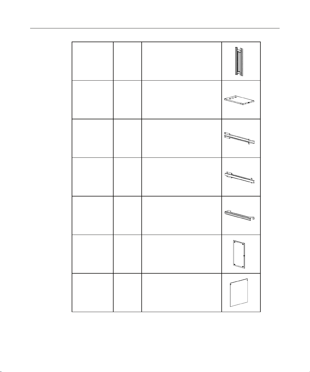
C4
D
E1
E2
F
1 piece Upper left rear vertical frame
piece (with Retma rail attached)
1 piece Rack top
1 piece Right depth rail
1 piece Left depth rail
2 pieces Rear door support
G
2 pieces Rear door
H
4 pieces Side panel
Page 13
Assembling the HP 5642 Rack 13
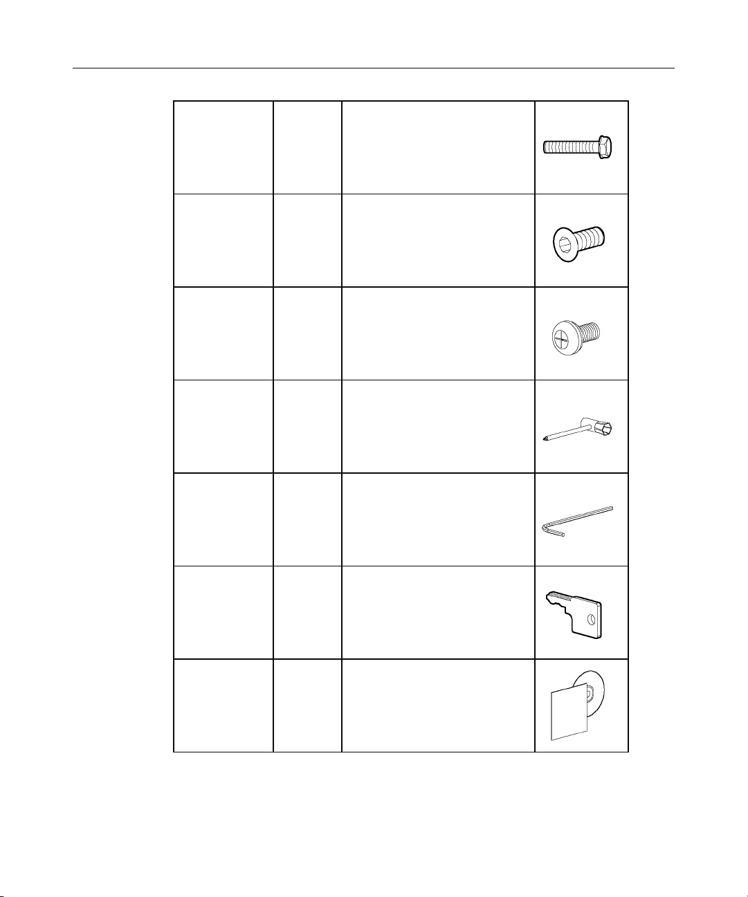
I
J
K
—
—
1 bag Bolts
1 bag Screws
1 bag Screws
1 tool Phillips screwdriver with socket
tool
1 tool Allen wrench
—
1 set Key
—
1 set Documentation Kit
Extra hardware might be included for your convenience.
Page 14

14 HP 5642 Rack User Guide
Required Tools
The following tools are required for some procedures:
• Included with this kit
− Allen wrench
− Phillips screwdriver with socket tool
− Keys
• Not included with this kit
− Step ladder
− Flat-head screwdriver (quarter-wide)
For comfort and efficiency while setting up your rack, use power tools where
applicable.
Assembling the HP 5642 Rack
CAUTION: Be sure that the HP 5642 Rack parts are
assembled in the correct locations according to the following
illustrations.
CAUTION: Do not exceed the maximum load capacity, 680.38
kg (1,500 lb), for this rack.
NOTE: For your convenience, the rack components are packaged to
follow the installation steps.
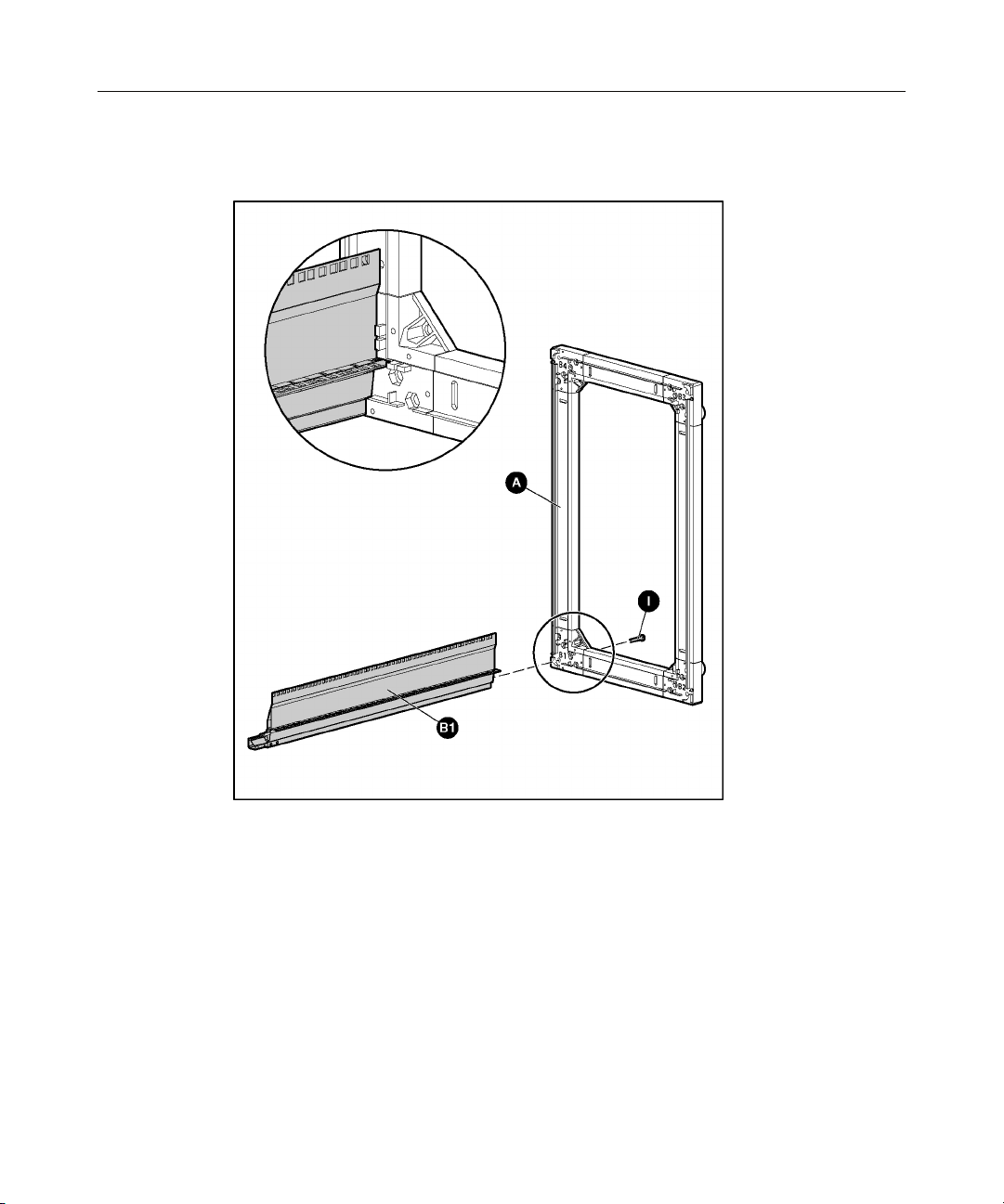
1. Place the rack base A in the location you have selected for the HP 5642
Rack.
2. Adjust the leveling feet if necessary.
CAUTION: Two people might be needed to lift and stabilize
certain components during this assembly.
Page 15
Assembling the HP 5642 Rack 15
3. Attach B1 to A using one I hardware bolt. Fully tighten the I hardware bolt
before proceeding to the next step.
Page 16
16 HP 5642 Rack User Guide
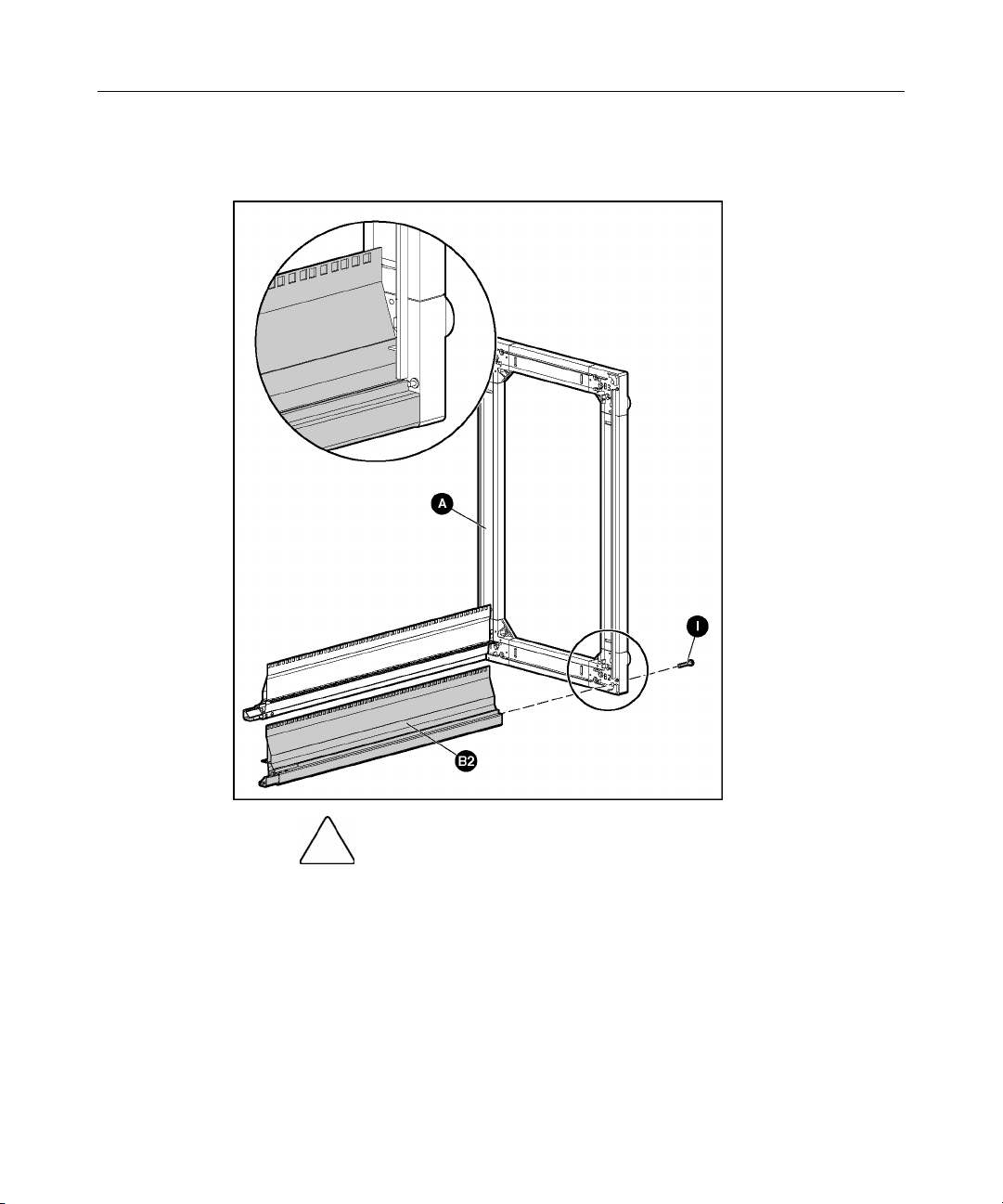
4. Attach B2 to A using one I hardware bolt. Fully tighten the I hardware bolt
before proceeding to the next step.
CAUTION: Two people might be needed to lift and stabilize
certain components during this assembly.
Page 17
Assembling the HP 5642 Rack 17
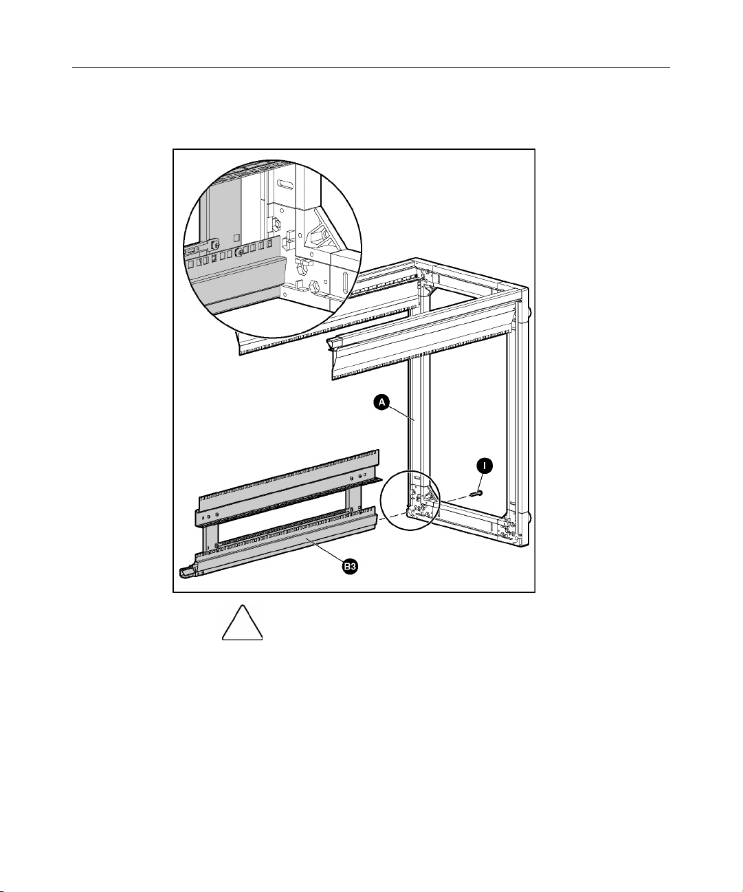
5. Attach B3 to A using one I hardware bolt. Fully tighten the I hardware bolt
before proceeding to the next step.
CAUTION: Two people might be needed to lift and stabilize
certain components during this assembly.
Page 18
18 HP 5642 Rack User Guide
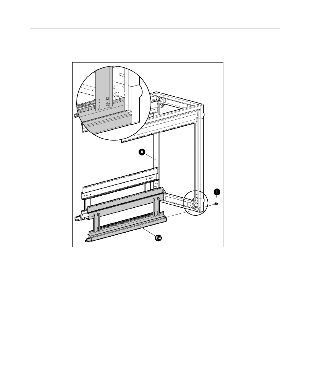
6. Attach B4 to A using one I hardware bolt. Fully tighten the I hardware bolt
before proceeding to the next step.
Page 19

Assembling the HP 5642 Rack 19
7. Attach C1 to B1 using four J hardware screws. Fully tighten the J hardware
screws before proceeding to the next step.
Page 20

20 HP 5642 Rack User Guide
8. Attach C2 to B2 using four J hardware screws. Fully tighten the J hardware
screws before proceeding to the next step.
Page 21

Assembling the HP 5642 Rack 21
9. Attach C3 to B3 using four J hardware screws. Fully tighten the J hardware
screws before proceeding to the next step.
Page 22

22 HP 5642 Rack User Guide
10. Attach C4 to B4 using four J hardware screws. Fully tighten the J hardware
screws before proceeding to the next step.
WARNING: Be sure that D is assembled in the correct
location according to the following illustration. C1 and C2 should
meet D where the HP logo is located, while C3 and C4 should meet
D where the cable egress holes are located. The HP logo is on the
front of the rack.
Page 23

Assembling the HP 5642 Rack 23
11. Attach D to C1, C2, C3, and C4 using four I hardware bolts. Fully tighten
the I hardware bolts before proceeding to the next step.
Page 24

24 HP 5642 Rack User Guide
12. Attach E1 to C2, C3, B2, and B3 using six K hardware screws. Fully tighten
the K hardware screws before proceeding to the next step.
Page 25

Assembling the HP 5642 Rack 25
13. Attach E2 to B1, B4, C1, and C4 using six K hardware screws. Fully tighten
the K hardware screws before proceeding to the next step.
Page 26

26 HP 5642 Rack User Guide
14. Attach F to C3 and C4 using two K hardware screws. Fully tighten the K
hardware screw before proceeding to the next step.
Page 27

Assembling the HP 5642 Rack 27
15. Attach F to B3 and B4 using two K hardware screws. Fully tighten the K
hardware screws before proceeding to the next step.
16. Attach G to F.
a. Position the bottom corner of G so that the pin on F is inserted into the
hole on G.
b. Using a tool, push down on the pin spring through the slot on G until the
pin is de-pressed.
c. Slide the top corner of G under the corner of the rack frame.
d. Remove the tool from the slot on G. The pin pops into place.
Page 28

28 HP 5642 Rack User Guide
e. Repeat for the other G piece.
WARNING: To reduce the risk of personal injury or
damage to the equipment, be sure that the H pieces are secured to
the rack frame by turning the quarter locks before releasing them.
17. Attach H to A.
a. Position H so that the pins on A are inserted into the holes on H.
b. Rotate H toward the rack.
c. Using a tool, turn the quarter locks on H to latch it into place.
Page 29

Assembling the HP 5642 Rack 29
d. Repeat for the other side of the rack.
WARNING: To reduce the risk of personal injury or
damage to the equipment, be sure that the H pieces are secured to
the rack frame by turning the quarter locks before releasing them.
18. Attach H to E.
a. Position H so that the pins on E are inserted into the holes on H.
b. Rotate H toward the rack.
c. Using a tool, turn the quarter locks on H to latch it into place.
Page 30

30 HP 5642 Rack User Guide
d. Repeat for the other side of the rack.
Installation is complete.
Page 31

31
Configuration Factors
In This Section
Maximum Load Capacity .............................................................................................................31
Rack Caution ................................................................................................................................31
Configuration Factors...................................................................................................................32
Rack Configuration Software .......................................................................................................32
Custom Builder Online Modes of Operation................................................................................32
Component Placement..................................................................................................................33
Additional Considerations............................................................................................................33
Optimum Environment.................................................................................................................35
Multiple Racks..............................................................................................................................37
Maximum Load Capacity
Rack Caution
CAUTION: Do not exceed the maximum load capacity, 680.38
kg (1,500 lb), for this rack.
CAUTION: To reduce the risk of personal injury or damage to
the equipment, be sure that:
Page 32

32 HP 5642 Rack User Guide
• This procedure is performed after you have read these instructions
completely.
• You select a location to set up your rack. This location should be as
close as possible to the permanent site for your rack.
• The leveling feet are extended to the floor to stabilize the rack.
• Two or more people are available to lift and stabilize the product
pieces during assembly.
• After you install the side panels, they are secured to the rack frame
before releasing them.
• The maximum load capacity for this rack is 680.38 kg (1,500 lb).
Configuration Factors
Before populating your new rack, you must plan the placement of each
component. Factors of each component, such as weight, accessibility, power,
temperature, and airflow requirements, affect installation order and component
placement in the rack.
Rack Configuration Software
To help you plan your rack configuration more efficiently, HP provides Custom
Builder, a powerful Web-based service enabling you to build, store, and export
end-to-end rack configurations. The latest version of the software is available on
the HP website (http://h30099.www3.hp.com/configurator/eco-
cb/custombuilder.asp).
Custom Builder Online Modes of Operation
Custom Builder has two modes of operation:
• Help-Me-Build-A-New-Solution Mode—Includes a simple interview session
to help determine your rack and component needs, as well as the necessary
power products and rack assembly devices needed to complete the final rack
assembly
• Let-Me-Build-A-New-Solution-Myself Mode—Enables you to select the
individual devices that are required for your rack configuration
Page 33

Configuration Factors 33
Component Placement
Apply the following rules to the physical placement of components in the HP
5642 Rack:
• Weight—Sort all of the components by weight, placing the heaviest
components at the bottom of the rack.
• KVM Switch—Mount the switch either behind the keyboard or within a
sidewall cavity to provide a 0U space solution.
• RKM—Install the RKM at a level that is the correct ergonomic position
where your shoulders and neck are relaxed.
• Monitor—Arrange the screen a minimum of 4Us above the keyboard tray.
• Rack-mountable flat-panel monitor—Select a position to accommodate the
desired viewing height (a minimum of 4Us above the keyboard tray).
• Balance—Be sure to balance the weight load between the racks, placing the
heaviest components at the bottom of the rack. For example, if you have
several UPS units and several servers, do not put all of the UPS units into
one rack. Distribute them evenly in the bottom positions of each rack.
For further information regarding component placement, refer to the Important
Safety Instructions that are shipped with the rack. Also, refer to the Safety and
Comfort Guide—Precautions for Server and Network Products on the HP
website (http://www.hp.com
) (search for Safety and Comfort Guide).
Additional Considerations
The following are additional items to consider, based on your specific rack
configuration:
• Power—If a UPS is installed, do not exceed its output rating. Be sure to
review the installation instructions provided with each component for
important cautions and warnings.
• PDUs—Install PDUs before installing other components.
Page 34

34 HP 5642 Rack User Guide
• Height—The height of the rack and of rack-mountable components is
measured in U increments. When you are configuring your rack installation,
remember that the total U measurement of the components you want to
install cannot exceed the stated U height of the rack.
• Keyboard—The rack keyboard requires installation of a 1U Keyboard
Drawer Rack Option Kit.
• Monitor—The monitor requires installation of a Monitor/Utility Shelf rack
Option Kit unless you are using a rack-mountable flat-panel monitor.
• Server Console Switch—If a console switch is configured, use the CPU-to-
console switch cable included with the server. The standard distance between
the console switch and the keyboard, monitor, and mouse can vary by 3-, 7-,
12-, 20-, and 40-ft lengths.
NOTE: National electrical regulations governing the installation of
building wiring require that an appropriate cable, meeting fire-safety
standards, must be used any time cabling is routed:
• Through an overhead drop-ceiling
• Under raised flooring
• From room to room
• From floor to floor
Be sure that the cable jacket or sleeving is made of material that does
not burn easily and does not exude toxic fumes when exposed to heat.
Be sure that the cable you have selected is appropriate for your
installation site. If you require a U.S. plenum-rated (CL2P) cable,
contact your local HP authorized reseller to obtain any of the following
options:
• 149363-B21-20-foot plenum cable
• 149364-B21-40-foot plenum cable
• Baying Rack Option Kits—The number of baying kits needed to join a
series of racks is one less than the number of racks in the suite. Each baying
kit supplies parts to bay two cabinets on 600 mm (24 inches) center line
spacing.
• Side Panels—Only one set of side panels is required for each row of bayed
racks.
• Stabilizing Kit—A stand-alone rack requires a stabilizing kit.
Page 35

Configuration Factors 35
Optimum Environment
Specific requirements for space, power, temperature, and airflow must be met to
provide optimum performance with minimum maintenance for your rack
environment.
For additional information, refer to the Best Practices document on the HP
website (http://www.hp.com).
Space Requirements
When deciding where to place your rack:
• At least 1,219 mm (48 inches) of clearance is needed all the way around the
pallet and above the rack to enable the removal of the packing material.
• At least 1,219 mm (48 inches) of clearance is needed in front of the rack to
enable the door to open completely.
• At least 762 mm (30 inches) of clearance is needed in the rear of the rack to
provide access to components.
• At least 380 mm (15 inches) of clearance is needed around a power supply to
facilitate servicing.
Power Requirements
When planning for power distribution requirements for your rack configuration:
• The power load must be balanced between available AC supply branch
circuits.
• The overall system AC current load must not exceed 80% of the branch
circuit AC current rating.
• If a UPS is used, the load should not exceed 80% of the marked electrical
current rating for the UPS.
Page 36

36 HP 5642 Rack User Guide
This equipment must be installed in accordance with local and regional electrical
regulations governing the installation of information technology equipment by
licensed electricians. This equipment is designed to operate in installations
covered by the Nation Electric Code (ANSI/NFPA-70, 1993) and the code for
protection of Electronic Computer/Data Processing Equipment (NFPA-75, 1992).
For electrical power ratings on options, refer to the products rating label or user
documentation supplied with that option.
Temperature Requirements
To ensure continued safe and reliable equipment operation, install or position the
rack in a well ventilated, climate-controlled environment.
The operating temperature inside the rack is always higher than the room
temperature and is dependent on the configuration of equipment in the rack.
Check the TMRA for each piece of equipment before installation.
CAUTION: To reduce the risk of damage to the equipment
when installing third-party options:
• Do not permit optional equipment to impede airflow around the HP
5642 Rack or to increase the internal rack temperature beyond the
maximum allowable limits.
• Do not exceed the manufacturer’s TMRA.
Airflow Requirements
HP rack-mountable products typically draw in cool air through the front and
exhaust warm air out through the rear of the rack. The front door of the rack,
therefore, must be adequately ventilated to enable ambient room air to enter the
rack, and the rear door must be adequately ventilated to enable the warm air to
escape the rack. Do not block the ventilation apertures.
Blanking Panels
If the front of the rack is not completely filled with components, the remaining
gaps between the components can cause changes in the airflow, which can
adversely affect cooling within the rack. Cover these gaps with blanking panels.
Page 37

Configuration Factors 37
Multiple Racks
Increasing space and stability, HP 5642 Racks can be bayed together by
installing the HP 5642 Baying Rack Option Kit. The HP 5642 Baying Rack
Option Kit joins multiple racks of the same series, height, and depth.
Observe the following tips when using multiple-rack configurations:
• The stabilizing kit is optional with bayed racks.
• The number of baying kits needed is one less than the total number of racks.
• Position and install either baying option kit before populating the racks with
components.
Page 38

Page 39

39
Installing Components
In This Section
General Guidelines .......................................................................................................................39
Preparing the Rack for Component Installation ...........................................................................41
Installing Components..................................................................................................................44
General Guidelines
IMPORTANT: HP strongly recommends that you configure the rack
using the Custom Builder (http://h30099.www3.hp.com/configurator/eco-
cb/custombuilder.asp) before beginning the installation process.
WARNING: To reduce the risk of personal injury or
damage to the equipment, adequately stabilize the rack before
extending a component outside the rack. Extend only one
component at a time. A rack may become unstable if more than
one component is extended.
WARNING: To reduce the risk of personal injury or
damage to the equipment, always load the heaviest item first from
the bottom of the rack up. This makes the rack bottom-heavy and
helps prevent the rack from becoming unstable. Refer to
Configuration Factors (on page 32
WARNING: To reduce the risk of personal injury or
damage to the equipment, be sure that:
).
Page 40

40 HP 5642 Rack User Guide
• The leveling feet are extended to the floor.
• The full weight of the rack rests on the leveling feet.
• The stabilizing feet are attached to the rack if it is a single-rack
installation.
• The racks are coupled together in multiple-rack installations.
• Only one component is extended at a time. A rack may become
unstable if more than one component is extended for any
reason.
CAUTION: To reduce the risk of damage to the equipment
when installing third-party options:
• Do not permit optional equipment to impede airflow around the HP
5642 Rack or to increase the internal rack temperature beyond the
maximum allowable limits.
• Do not exceed the manufacturer’s TMRA.
Observe the general guidelines when loading your components:
• For detailed instructions on installing specific component or third-party
hardware, refer to the user documentation that was shipped with that
component.
• Before installing components into the rack, refer to Electrostatic Discharge
(on page 51
).
• Use the configuration prepared by the Custom Builder as a guideline for
installation components.
• Load the heavier components first from the bottom of the rack.
• Be sure to balance the weight load between bayed racks. For example, if you
have several UPS units and several servers, do not pull all of the UPS units
into one rack. Instead distribute them evenly in the bottom positions of each
rack.
• Allow a minimum clearance of 76 cm (30 inches) between the wall and the
rear of the rack to provide adequate access for installation and service.
Page 41

Installing Components 41
Preparing the Rack for Component Installation
• Checking the Hardware (on page 41)
• Removing the Side Panels (on page 41)
• Removing the Rack Doors (on page 43
Checking the Hardware
After unpacking the component to be installed, locate the documentation that was
shipped with that component. Verify that you received all of the listed hardware
pieces.
You will typically have extra fasteners after completing your component
installation.
IMPORTANT: Retain the extra fasteners for future use.
Removing the Side Panels
1. Remove H from A.
a. Place one of your palms on H. Using your other hand and a tool, turn the
quarter-turn locks on H to unlatch H.
b. Slowly rotate H so that you are able to remove it from the pins on A.
)
Page 42

42 HP 5642 Rack User Guide
c. Repeat for the other side of the rack.
2. Remove H from E.
a. Place one of your palms on H. Using your other hand and a tool, turn the
quarter-turn locks on H to unlatch H.
b. Slowly rotate H so that you are able to remove it from the pins on E.
Page 43

Installing Components 43
c. Repeat for the other side of the rack.
Removing the Rack Doors
To provide access to all sides of the rack while you are installing the various
components, first remove the rack doors. If your rack has side panels, also
remove them before installing mounting brackets and other hardware.
To remove the rear rack doors:
1. Using a tool, push down on the pin spring through the slot on G.
2. Slide the top corner of G out from under the corner of the rack.
Page 44

44 HP 5642 Rack User Guide
3. Remove the tool from the slot on G.
4. Remove the bottom corner of G from the pin on F.
Installing Components
NOTE: Install the stabilizer foot before any component.
IMPORTANT: These installation instructions are for standard
installations. For specific installation instructions, refer to the
documentation included with your component.
Page 45

Installing Components 45
The following steps outline the sequence for installing rack-mountable
components in a rack. Install 0U devices first, such as PDUs, console switches,
and so on.
1. Use the rack template ("Using the Rack Template" on page 45
and mark the rack for correct placement of the installation hardware.
2. Install the cage nuts ("Installing the Cage Nuts" on page 46
required).
3. Prepare and install the rails into the rack.
4. Prepare and install the component into the rack and secure it.
5. Install the component into the rack and secure it.
6. Attach the cable management arm to the rack and then to the component.
7. Attach any cables and power cords, being sure that you adhere to all cautions
and warnings contained in the individual component installation instructions.
8. Remove the cable access panel and route the cables.
Using the Rack Template
Use the template that was shipped with your rack-mountable component to mark
the location of the mounting hardware on the mounting rails of the rack.
Align the lower edge of the rack template with the top of the previous rack
component, and push the tabs in to hold the rack template in place. Mark the rack
to indicate where the components are to be located.
) to measure
) into the rack (if
Page 46

46 HP 5642 Rack User Guide
CAUTION: Always plan the rack installation so that the
heaviest item is on the bottom of the rack. Install the heaviest item first,
and continue to populate the rack from the bottom to the top.
NOTE: Rack components are removed for clarity.
Installing the Cage Nuts
Use the cage nut insertion tool to install the cage nuts on the inside of the
mounting rails.
NOTE: The cage nut insertion tool and the cage nuts are not included
with this rack.
1. Hook the bottom lip of the cage nut in the square-rail perforation.
2. Insert the tip of the insertion tool through the perforation, and hook the top
lip of the cage nut.
Page 47

Installing Components 47
3. Use the insertion tool to pull the cage nut through the hole until the top lip
snaps into position.
Page 48

Page 49

49
Specifications
In This Section
HP 5642 Rack Specifications .......................................................................................................49
HP 5642 Rack Specifications
U height Width Depth Static
Load
42 U 600 mm
(23.62 in.)
1000
mm
(39.37
680.38
kg (1,500
lb)
in.)
Shipping
Options
Flat ship
(-B21)
Color
Graphite
metallic
Page 50

Page 51

51
Electrostatic Discharge
In This Section
Preventing Electrostatic Discharge...............................................................................................51
Grounding Methods to Prevent Electrostatic Discharge...............................................................52
Preventing Electrostatic Discharge
To prevent damaging the system, be aware of the precautions you need to follow
when setting up the system or handling parts. A discharge of static electricity
from a finger or other conductor may damage system boards or other staticsensitive devices. This type of damage may reduce the life expectancy of the
device.
To prevent electrostatic damage:
• Avoid hand contact by transporting and storing products in static-safe
containers.
• Keep electrostatic-sensitive parts in their containers until they arrive at staticfree workstations.
• Place parts on a grounded surface before removing them from their
containers.
• Avoid touching pins, leads, or circuitry.
• Always be properly grounded when touching a static-sensitive component or
assembly.
Page 52

52 HP 5642 Rack User Guide
Grounding Methods to Prevent Electrostatic Discharge
Several methods are used for grounding. Use one or more of the following
methods when handling or installing electrostatic-sensitive parts:
• Use a wrist strap connected by a ground cord to a grounded workstation or
computer chassis. Wrist straps are flexible straps with a minimum of
1 megohm ±10 percent resistance in the ground cords. To provide proper
ground, wear the strap snug against the skin.
• Use heel straps, toe straps, or boot straps at standing workstations. Wear the
straps on both feet when standing on conductive floors or dissipating floor
mats.
• Use conductive field service tools.
• Use a portable field service kit with a folding static-dissipating work mat.
If you do not have any of the suggested equipment for proper grounding, have an
authorized reseller install the part.
For more information on static electricity or assistance with product installation,
contact your authorized reseller.
Page 53

53
Technical Support
In This Section
HP Contact Information................................................................................................................53
Before You Contact HP................................................................................................................53
HP Contact Information
For the name of the nearest HP authorized reseller:
• In the United States, call 1-800-345-1518.
• In Canada, call 1-800-263-5868.
• In other locations, refer to the HP website (http://www.hp.com
For HP technical support:
• In North America:
− Call 1-800-HP-INVENT (1-800-474-6836). This service is available
24 hours a day, 7 days a week. For continuous quality improvement,
calls may be recorded or monitored.
− If you have purchased a Care Pack (service upgrade), call 1-800-633-
3600. For more information about Care Packs, refer to the HP website.
(http://www.hp.com
• Outside North America, call the nearest HP Technical Support Phone Center.
For telephone numbers for worldwide Technical Support Centers, refer to the
HP website (http://www.hp.com
Before You Contact HP
Be sure to have the following information available before you call HP:
• Technical support registration number (if applicable)
).
)
).
Page 54

54 HP 5642 Rack User Guide
• Product serial number
• Product model name and number
• Applicable error messages
• Add-on boards or hardware
• Third-party hardware or software
• Operating system type and revision level
Page 55

55
Acronyms and Abbreviations
KVM
keyboard, video, and mouse
PDU
power distribution unit
RKM
rackmount keyboard monitor
TMRA
recommended ambient operating temperature
UPS
uninterruptible power system
Page 56

Page 57

57
Index
A
additional information 53
airflow requirements 36
assembling the rack 14
authorized reseller 53
B
Baying Rack Option Kit 37
blanking panels 36
C
cage nuts, installing 46
checking the hardware 41
component placement 33
configuration factors 31, 32
contacting HP 53
Custom Builder 32, 33
E
electrostatic discharge 51
G
general guidelines 39
grounding methods 52
I
installation overview 6
installation services 7
installing components 39, 44
installing the cage nuts 46
K
kit contents 10
L
Let Me Build A New Solution Myself Mode 32
M
maximum load capacity 9
multiple racks 37
O
Offset Baying Rack Option Kit 37
optimum environment 35
overview of installation process 44
overview, HP 5642 Rack 5
P
phone numbers 53
power requirements 35
preparing the rack for component
installation 41
H
Help Me Build A New Solution Mode 32
help resources 53
HP 5642 Rack specifications 49
HP Technical Support 53
R
rack configuration software 32
rack doors, removing 43
rack options 5
rack template 45
removing the rear doors 43
removing the side panels 41
required information 53
Page 58

58 HP 5642 Rack User Guide
required tools 14
S
side panels, removing 41
space requirements 35
specifications 49
static electricity 51
support 53
T
technical support 53
telephone numbers 53
temperature requirements 36
U
using the rack template 45
W
website, HP 53
 Loading...