

HP 5600-48XG-4QSFP+ Quick Start Manual
Quick Start Guide
2
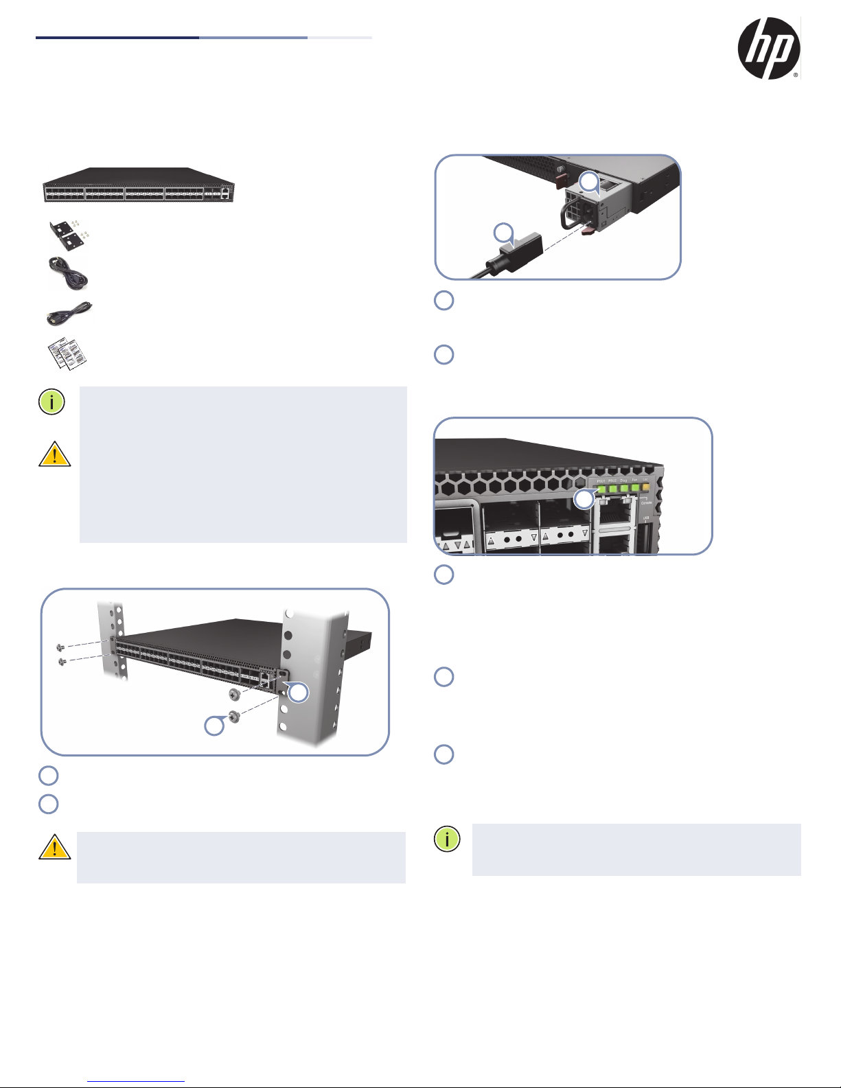
1
1
2
1
2
1
21112
48-Port 10G Top-of-Rack Switch
HP 5600-48XG-4QSFP+ Switch Series
1. Unpack the Switch and Check Contents
HP 5600-48XG-4QSFP+
Switch Series
10G Top-of-Rack Switch
Rack Mounting Kit—Contains two brackets and eight
screws for attaching the brackets to the switch.
Power Cord—Country-specific power cord(s)
Console Cable—RJ-45 to DB-9
Documentation—Quick Start Guide (this document)
and Safety and Regulatory Information
Note:
The switch has the Open Network Installer
Environment (ONIE) software pre-loaded, but no switch
software image pre-loaded.
Caution:
fan tray modules that are installed into its chassis. All
installed modules must have a matching airflow direction.
That is, all modules must have a front-to-back (F2B) airflow
direction, or all modules must have a back-to-front (B2F)
airflow direction. The airflow direction of PSU and fan tray
modules is indicated by labels on the modules.
The switch includes plug-in power supply and
3. Connect Power
Install one or two universal AC power modules in the switch.
The switch supports up to two PSUs that must have the
same matching airflow direction as the installed fan tray.
Connect an external AC power source to the modules.
4. Verify Switch Operation
2. Mount the Switch
Attach the brackets to the switch.
Use the screws supplied with the rack to secure the switch in
the rack.
Caution:
people. One person should position the switch in the rack,
while the other secures it using the rack screws.
Installing the switch in a rack requires two
Verify basic switch operation by checking the system LEDs.
When operating normally, the PSU1/PSU2, Diag, and Fan
LEDs should all be on green.
5. Perform Initial System Boot
If the network operating system (NOS) installer is located on
a network server, first connect the RJ-45 Management
(Mgmt) port to the network using 100-ohm Category 5, 5e
or better twisted-pair cable. (Not required if the NOS
installer is located on attached storage.)
Boot the switch. Wait for the ONIE software to locate and
execute the NOS installer, and then wait for the installer to
load the NOS software image.
Subsequent switch boots will bypass ONIE and directly run
the NOS software.
Note:
Refer to the network operating system (NOS) installer
and NOS documentation for details on software options and
set up for ONIE.
– 1 –
E012015-CS-R01

Quick Start Guide
2
1
1
2
6. Connect Network Cables
For the RJ-45 Management port, connect 100-ohm Category
5, 5e or better twisted-pair cable.
Connect DAC cables to the SFP+/QSFP+ slots. Or first install
SFP+/QSFP+ transceivers and then connect fiber optic
cabling to the transceiver ports.
The following transceivers are supported:
◆
40GBASE-CR4
◆
40GBASE-SR4
◆
10GBASE-CR
◆
10GBASE-SR
◆
1000BASE-SX
◆
1000BASE-LX
Note:
As connections are made, check the port status LEDs
to be sure the links are valid.
Hardware Specifications
Chassis
Size W x D x H:
Weight 8.395 kg (18.51 lb), with two installed power supply
Temperature Operating: 0° C to 40° C (32° F to 104° F)
Humidity Operating: 5% to 95% (non-condensing)
Operating
Altitude
Acoustics Noise Emission LpA=60 dB at virtual workspace
Power Supply
AC Input 100-240 VAC, 50-60 Hz, 6-3 A
DC Output 5 VDC @ 3 A
Power Supply 100-240 VAC, 50-60 Hz, auto-sensing; hot
Power
Consumption
438.4 x 473 x 43.4 mm (17.26 x 18.62 x 1.71 inches)
modules
Storage: -40° C to 70° C (-40° F to 158° F)
Up to 3000 m (10,000 ft)
according to DIN 45635 T.19
12 VDC @ 33 A
pluggable
400 Watts @ 240V/100V per module
165 Watts maximum
Maximum
Current
6 A @ 100 VAC
3 A @ 240 VAC
Size W x D x H:
54.5 x 220 x 40.25 mm (2.15 x 8.66 x 1.58 inches)
Regulatory Compliances
Emissions EN 55022:2010, Class A
EN 61000-3-2:2009, Class A
EN 61000-3-3:2008
FCC Class A
VCCI Class A
CE Mark
Immunity EN 55024:2010
IEC 61000-4-2/3/4/5/6/8/11
Safety UL (CSA 22.2 No 60950-1 & UL60950-1)
CB (IEC/EN60950-1)
– 2 –
 Loading...