

HP 5510 HI Installation Manual

HPE 5510 HI Switch Series
Installation Guide
Part number:
Document version: 6W100-20151023

Legal and notice information
© Copyright 2015 Hewlett-Packard Development Company, L.P.
No part of this documentation may be reproduced or transmitted in any form or by any means without
prior written consent of Hewlett-Packard Development Company, L.P.
The information contained herein is subject to change without notice.
HEWLETT-PACKARD COMPANY MAKES NO WARRANTY OF ANY KIND WITH REGARD TO THIS
MATERIAL, INCLUDING, BUT NOT LIMITED TO, THE IMPLIED WARRANTIES OF MERCHANTABILITY
AND FITNESS FOR A PARTICULAR PURPOSE. Hewlett-Packard shall not be liable for errors contained
herein or for incidental or consequential damages in connection with the furnishing, performance, or use
of this material.
The only warranties for HP products and services are set forth in the express warranty statements
accompanying such products and services. Nothing herein should be construed as constituting an
additional warranty. HP shall not be liable for technical or editorial errors or omissions contained herein.
i

Contents
Preparing for installation ················································································································································· 1
Safety recommendations ·················································································································································· 1
Examining the installation site·········································································································································· 2
Temperature/humidity ············································································································································· 2
Cleanliness ································································································································································ 3
EMI ············································································································································································· 3
Laser safety ································································································································································ 3
Installation tools ································································································································································· 4
Installation accessories ····················································································································································· 4
Installing the switch ·························································································································································· 6
Installing the switch in a 19-inch rack ····························································································································· 7
Installation accessories ············································································································································ 7
Mounting bracket kits ··············································································································································· 8
Rack-mounting by using front mounting brackets ·································································································· 9
Rack-mounting by using front and rear mounting brackets (HPE 5510 24G PoE+ 4SFP+ HI and HPE 5510
48G PoE+ 4SFP+ HI) ············································································································································ 11
Mounting the switch on a workbench ·························································································································· 14
Grounding the switch ···················································································································································· 14
Grounding the switch with a grounding strip ····································································································· 15
Grounding the switch with a grounding conductor buried in the earth ground ············································· 17
Grounding the switch by using the AC power cord ·························································································· 18
Installing/removing a power supply ···························································································································· 19
Installing a PSR150 power supply ······················································································································· 19
Removing a PSR150 power supply ····················································································································· 20
Installing a PSR720-56A/PSR1110-56A power supply ··················································································· 21
Removing a PSR720-56A/PSR1110-56A power supply ·················································································· 22
Connecting the power cord ·········································································································································· 23
Connecting the PSR150-D1 power supply ········································································································· 23
Connecting the PSR720-56A/PSR1110-56A/PSR150-A1 power supply ······················································ 24
Installing/removing an interface card ························································································································· 25
Installing an interface card ··································································································································· 25
Removing an interface card ································································································································· 27
Verifying the installation ················································································································································ 27
Accessing the switch for the first time ·························································································································· 29
Setting up the configuration environment ···················································································································· 29
Connecting the console cable······································································································································· 29
Connecting the USB mini console cable ······················································································································ 30
Setting terminal parameters ·········································································································································· 32
Powering on the switch·················································································································································· 32
Setting up an IRF fabric ················································································································································· 34
IRF fabric setup flowchart ·············································································································································· 34
Planning IRF fabric setup ··············································································································································· 35
Planning IRF fabric size and the installation site ································································································ 35
Identifying the master switch and planning IRF member IDs ············································································ 35
Planning IRF topology and connections ·············································································································· 36
Identifying physical IRF ports on the member switches ····················································································· 37
Planning the cabling scheme ······························································································································· 37
ii

Configuring basic IRF settings ······································································································································· 40
Connecting the physical IRF ports ································································································································ 40
Verifying the IRF fabric setup ········································································································································ 41
Maintenance and troubleshooting ······························································································································· 42
Power supply failure ······················································································································································ 42
Symptom ································································································································································· 42
Solution ··································································································································································· 42
Fan tray failure ······························································································································································· 42
Removing a fan tray ·············································································································································· 43
Installing a fan tray ··············································································································································· 43
Configuration terminal problems ·································································································································· 44
No terminal display ·············································································································································· 44
Garbled terminal display ······································································································································ 44
Appendix A Chassis views and technical specifications ··························································································· 46
Chassis views ································································································································································· 46
HPE 5510 24G SFP 4SFP+ HI ····························································································································· 46
HPE 5510 24G 4SFP+ HI ···································································································································· 47
HPE 5510 24G PoE+ 4SFP+ HI ·························································································································· 48
HPE 5510 48G 4SFP+ HI ···································································································································· 49
HPE 5510 48G PoE+ 4SFP+ HI ·························································································································· 50
Technical specifications ················································································································································· 51
Appendix B FRUs and compatibility matrixes ············································································································· 55
FRUs and compatibility matrixes ·································································································································· 55
Hot swappable power supplies ···································································································································· 55
Hot swappable interface cards ···································································································································· 56
Interface card operating mode ···························································································································· 57
Connecting cables to the copper ports on the interface cards ········································································· 57
Appendix C Ports and LEDs ·········································································································································· 58
Ports ················································································································································································· 58
Console port··························································································································································· 58
Management Ethernet port ··································································································································· 58
USB port ································································································································································· 58
10/100/1000Base-T autosensing Ethernet port ······························································································· 59
100/1000Base-X SFP port··································································································································· 59
SFP+ port ································································································································································ 60
QSFP+ port ···························································································································································· 62
Combo interface ···················································································································································· 64
LEDs ················································································································································································· 64
System status LED··················································································································································· 64
Power supply status LED ······································································································································· 65
Port mode LED ························································································································································ 65
10/100/1000Base-T autosensing Ethernet port LED ······················································································· 66
100/1000Base-X SFP port LED ··························································································································· 66
SFP+ port LED ························································································································································ 67
Management Ethernet port LEDs ·························································································································· 67
Interface card status LED ······································································································································· 68
Fan tray status LED on the fan tray ······················································································································ 68
Port status LED on the interface card ··················································································································· 68
Input status LED and output status LED on the power supply ············································································ 68
iii

Appendix D Cooling system ········································································································································· 69
Index ················································································································································································ 70
iv

Product code
HPE description
Alias
HPE 5510 HI switches
JH145A
HPE 5510 24G 4SFP+ HI 1-slot Switch
HPE 5510 24G 4SFP+ HI
JH146A
HPE 5510 48G 4SFP+ HI 1-slot Switch
HPE 5510 48G 4SFP+ HI
JH147A
HPE 5510 24G PoE+ 4SFP+ HI 1-slot Switch
HPE 5510 24G PoE+ 4SFP+ HI
JH148A
HPE 5510 48G PoE+ 4SFP+ HI 1-slot Switch
HPE 5510 48G PoE+ 4SFP+ HI
JH149A
HPE 5510 24G SFP 4SFP+ HI 1-slot Switch
HPE 5510 24G SFP 4SFP+ HI
Power supplies
JD362A
HP A5800/A5500 150W AC Power Supply
PSR150-A1
JD366A
HP A5800/A5500 150W DC Power Supply
PSR150-D1
JG545A
HP X362 1110W AC PoE Power Supply
PSR720-56A
JG544A
HP X362 720W AC PoE Power Supply
PSR1110-56A
Interface cards
JH155A
HPE 5510 2-port QSFP+ Module
LSWM2QP2P
JH156A
HPE 5130/5510 10GBASE-T 2-port Module
LSWM2XGT2PM
JH157A
HPE 5130/5510 10GbE SFP+ 2-port Module
LSWM2SP2PM
Product code
RMN
HPE description
JH145A
BJNGA-AD0039
HPE 5510 24G 4SFP+ HI 1-slot Switch
JH146A
BJNGA-AD0040
HPE 5510 48G 4SFP+ HI 1-slot Switch
JH147A
BJNGA-AD0041
HPE 5510 24G PoE+ 4SFP+ HI 1-slot Switch
JH148A
BJNGA-AD0042
HPE 5510 48G PoE+ 4SFP+ HI 1-slot Switch
JH149A
BJNGA-AD0051
HPE 5510 24G SFP 4SFP+ HI 1-slot Switch
Preparing for installation
Table 1 HPE 5510 HI switches, power supplies, and interface cards
For regulatory identification purposes, the HPE 5510 HI switches are assigned regulatory model numbers
(RMNs), which are listed in the following table. These regulatory numbers should not be confused with
the marketing names HPE 5510 HI, or the product codes.
Safety recommendations
To avoid any equipment damage or bodily injury caused by improper use, read the following safety
recommendations before installation. Note that the recommendations do not cover every possible
hazardous condition.
1

Before cleaning the switch, remove all power cords from the switch. Do not clean the switch with wet
cloth or liquid.
Do not place the switch near water or in a damp environment. Prevent water or moisture from
entering the switch chassis.
Do not place the switch on an unstable case or desk. The switch might be severely damaged in case
of a fall.
Ensure good ventilation of the equipment room and keep the air inlet and outlet vents of the switch
free of obstruction.
Connect the yellow-green protection grounding cable before power-on.
Make sure the operating voltage is in the required range.
To avoid electrical shocks, do not open the chassis while the switch is operating or when the switch
is just powered off.
When replacing FRUs, including interface cards, power supplies, and fan trays, wear an ESD wrist
strap to avoid damaging the units.
Examining the installation site
The switch must be used indoors. You can mount your switch in a rack or on a workbench, but make sure:
Adequate clearance is reserved at the air inlet and outlet vents for ventilation.
The rack or workbench has a good ventilation system.
Identify the hot aisle and cold aisle at the installation site, and make sure ambient air flows into the
switch from the cold aisle and exhausts to the hot aisle.
Identify the airflow designs of neighboring devices, and prevent hot air flowing out of the bottom
device from entering the top device.
The rack is sturdy enough to support the switch and its accessories.
The rack or workbench is reliably grounded.
To ensure correct operation and long service life of your switch, install it in an environment that meets the
requirements described in the following subsections.
Temperature/humidity
Maintain temperature and humidity in the equipment room as described in "Appendix A Chassis views
and technical specifications."
Lasting high relative humidity can cause poor insulation, electricity creepage, mechanical property
change of materials, and metal corrosion.
Lasting low relative humidity can cause washer contraction and ESD and bring problems including
loose captive screws and circuit failure.
High temperature can accelerate the aging of insulation materials and significantly lower the
reliability and lifespan of the switch.
For the temperature and humidity requirements of different switch models, see "Technical specifications."
2

Substance
Concentration limit (particles/m³)
Dust
≤ 3 x 10⁴ (no visible dust on the tabletop over three days)
NOTE:
Dust diameter ≥ 5 μm
Gas
Maximum concentration (mg/m3)
SO2
0.2
H2S
0.006
NH3
0.05
Cl2
0.01
WARNING!
Do not stare into any fiber port when the switch has power. The laser light emitted from the optical fiber
might hurt your eyes.
Cleanliness
Dust buildup on the chassis might result in electrostatic adsorption, which causes poor contact of metal
components and contact points, especially when indoor relative humidity is low. In the worst case,
electrostatic adsorption can cause communication failure.
Table 2 Dust concentration limit in the equipment room
The equipment room must also meet strict limits on salts, acids, and sulfides to eliminate corrosion and
premature aging of components, as shown in Table 3.
Table 3 Harmful gas limits in the equipment room
EMI
All electromagnetic interference (EMI) sources, from outside or inside of the switch and application
system, adversely affect the switch in the following ways:
A conduction pattern of capacitance coupling.
Inductance coupling.
Electromagnetic wave radiation.
Common impedance (including the grounding system) coupling.
To prevent EMI, perform the following tasks:
If AC power is used, use a single-phase three-wire power receptacle with protection earth (PE) to
filter interference from the power grid.
Keep the switch far away from radio transmitting stations, radar stations, and high-frequency
devices.
Use electromagnetic shielding, for example, shielded interface cables, when necessary.
Laser safety
3
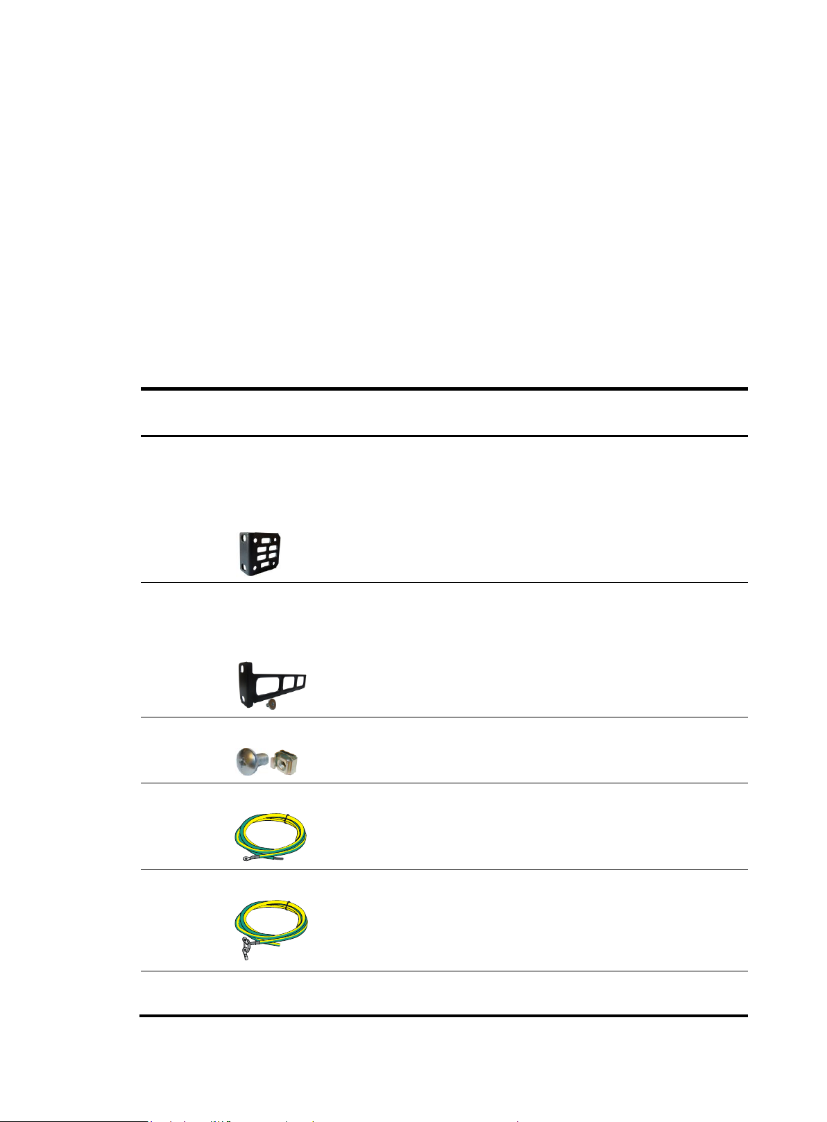
Product
code
Description
Quantity
Applicable models
5066-0850
1 U four-hole mounting
bracket kit (including one
pair of mounting brackets
and eight M4 countersunk
screws)
1 kit
All HPE 5510 HI switches
5190-0297
Rear mounting bracket kit
(including one pair of
mounting brackets and two
load-bearing screws)
1 kit
HPE 5510 24G PoE+ 4SFP+ 1-slot HI
HPE 5510 48G PoE+ 4SFP+ 1-slot HI
N/A
M6 screw and floating nut
As
required
All HPE 5510 HI switches
5185-9292
Grounding cable
1
HPE 5510 24G 4SFP+ HI
HPE 5510 48G 4SFP+ HI
HPE 5510 24G SFP 4SFP+ HI
5185-9408
Grounding cable
1
HPE 5510 24G PoE+ 4SFP+ HI
HPE 5510 48G PoE+ 4SFP+ HI
5185-8503
Power supply filler panel
1
HPE 5510 24G 4SFP+ HI
HPE 5510 48G 4SFP+ HI
The switch is Class 1 laser device.
Installation tools
Flat-blade screwdriver
Phillips screwdriver
ESD wrist strap
All these installation tools are user supplied.
Installation accessories
Table 4 Installation accessories
4
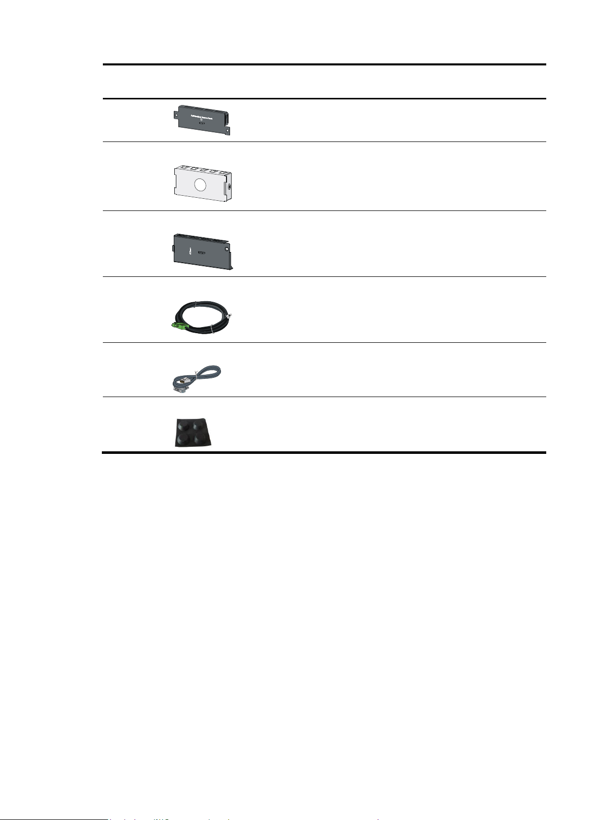
Product
code
Description
Quantity
Applicable models
HPE 5510 24G SFP 4SFP+ HI
5190-1774
Power supply filler panel
1
HPE 5510 24G PoE+ 4SFP+ HI
HPE 5510 48G PoE+ 4SFP+ HI
5190-0296
Interface card filler panel
1
All HPE 5510 HI switches
5185-9443
DC power cord
1
PSR150-D1
5184-6719
Console cable
1
All HPE 5510 HI switches
5184-7298
Rubber feet
4
All HPE 5510 HI switches
5

CAUTION:
Keep the tamper-proof seal on a mounting screw on the chassis cover intact, and if you want to open the
chassis, contact HPE for permission. Otherwise, HPE shall not be liable for any consequence.
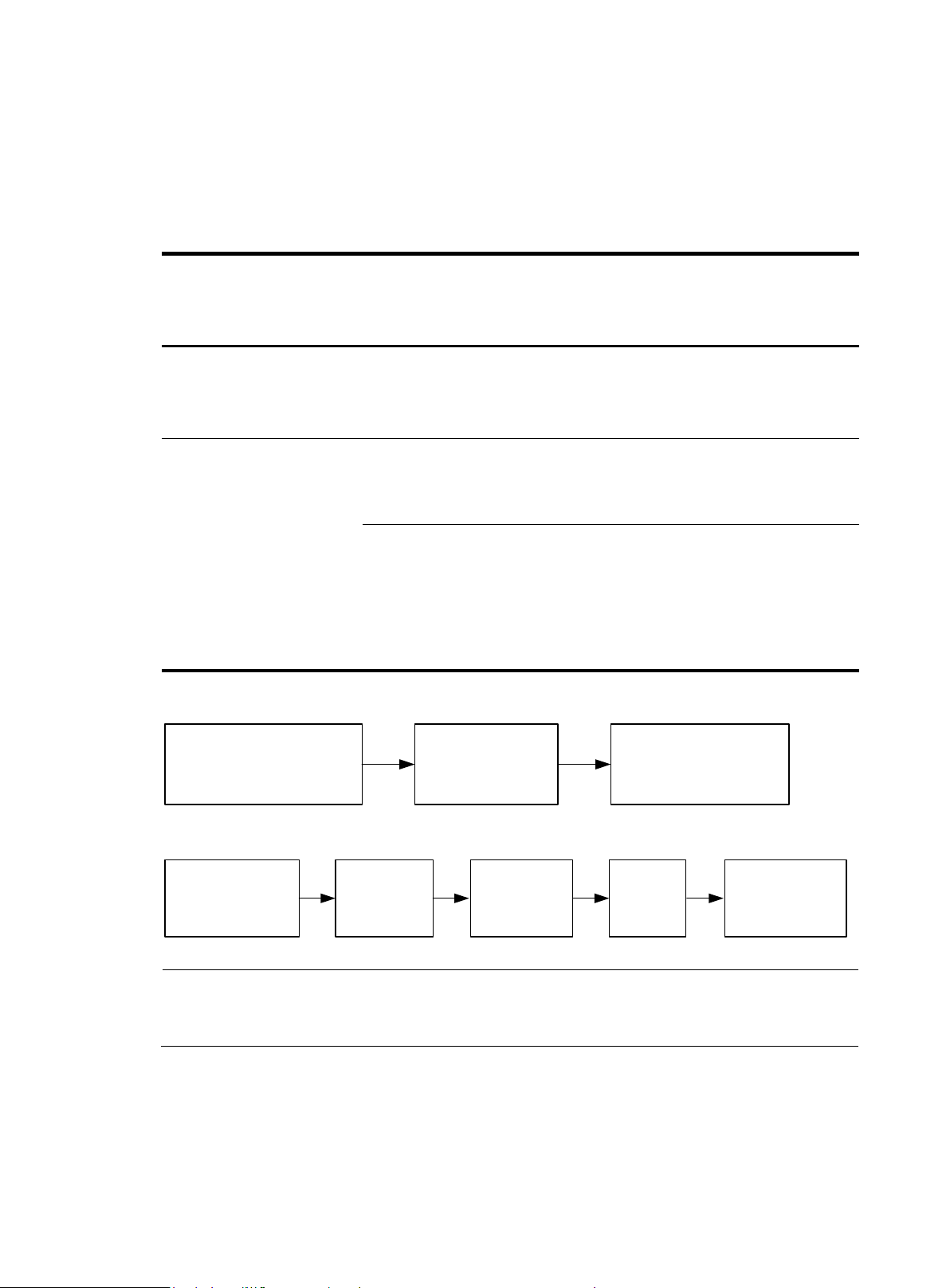
Ground the switch
Install the switch
Start
Connect power cords
Verify the installation
Turn on the circuit breaker
Select and install power
supplies
Hot-swap power
supplies?
Yes
No
Operating correctly?
Turn off the circuit
breaker
Troubleshoot the switch
No
Yes
Hot-swap cards?
Install interface cards
Yes
Troubleshoot the switch
Yes
No
End
No
Operating correctly?
Install transceiver modules
and cables
Installing the switch
Figure 1 Hardware installation flow
6
Chassis
Installati
on
accessori
es
Installation requirements
Installation procedure
HPE 5510 24G 4SFP+ HI
HPE 5510 48G 4SFP+ HI
HPE 5510 24G SFP
4SFP+ HI
Front
mounting
bracket
kit
The mounting bracket kit can be
installed on the port side, power
supply side, or the mid-mounting
position.
See "Rack-mounting by
using front mounting
brackets."
HPE 5510 24G PoE+
4SFP+ HI
HPE 5510 48G PoE+
4SFP+ HI
Front
mounting
bracket
kit
The front mounting bracket kit must be
installed on the mid-mounting
position.
See "Rack-mounting by
using front mounting
brackets."
Front and
rear
mounting
bracket
kits
The mounting bracket kit can be
installed on the port side or power
supply side.
The distance between the front
rack post and the rear rack post
must be in the range of 429 to 595
mm (16.89 to 23.42 in).
See "Rack-mounting by
using front and rear
mounting brackets (HPE
5510 24G PoE+ 4SFP+
HI and HPE 5510 48G
PoE+ 4SFP+ HI)."
NOTE:
If a rack shelf is available, you can put the switch on the rack shelf, slide the switch to an appropriate
location, and attach the switch to the rack by using the mounting brackets.
Attach the front
mounting brackets to the
two sides of the switch
Identify the mounting position (port
side, power side, or middle
position) for the mounting brackets
Mount the switch in the rack
Attach the front
mounting
brackets to the
two sides of the
switch
Attach the load
bearing screws to
the switch
Attach the
rear
mounting
brackets to
rack posts
Identify the mounting
position (port side or
power side) for the
mounting brackets
Mount the switch in
the rack
Installing the switch in a 19-inch rack
Installation accessories
Table 5 Installation accessories for the HPE 5510 HI switches
Figure 2 Rack-mounting procedure (1)
Figure 3 Rack-mounting procedure (2)
7
Mounting bracket kits
HPE 5510 24G SFP 4SFP+ HI
HPE 5510 24G 4SFP+ HI
HPE 5510 48G 4SFP+ HI
HPE 5510 24G PoE+ 4SFP+ HI
HPE 5510 48G PoE+ 4SFP+ HI
Front mounting bracket kit
Provided
Provided
Rear mounting bracket kit
Not required
Provided
Chassis rail and slide rail
Not required
Not required
Grounding cable
Provided
Provided
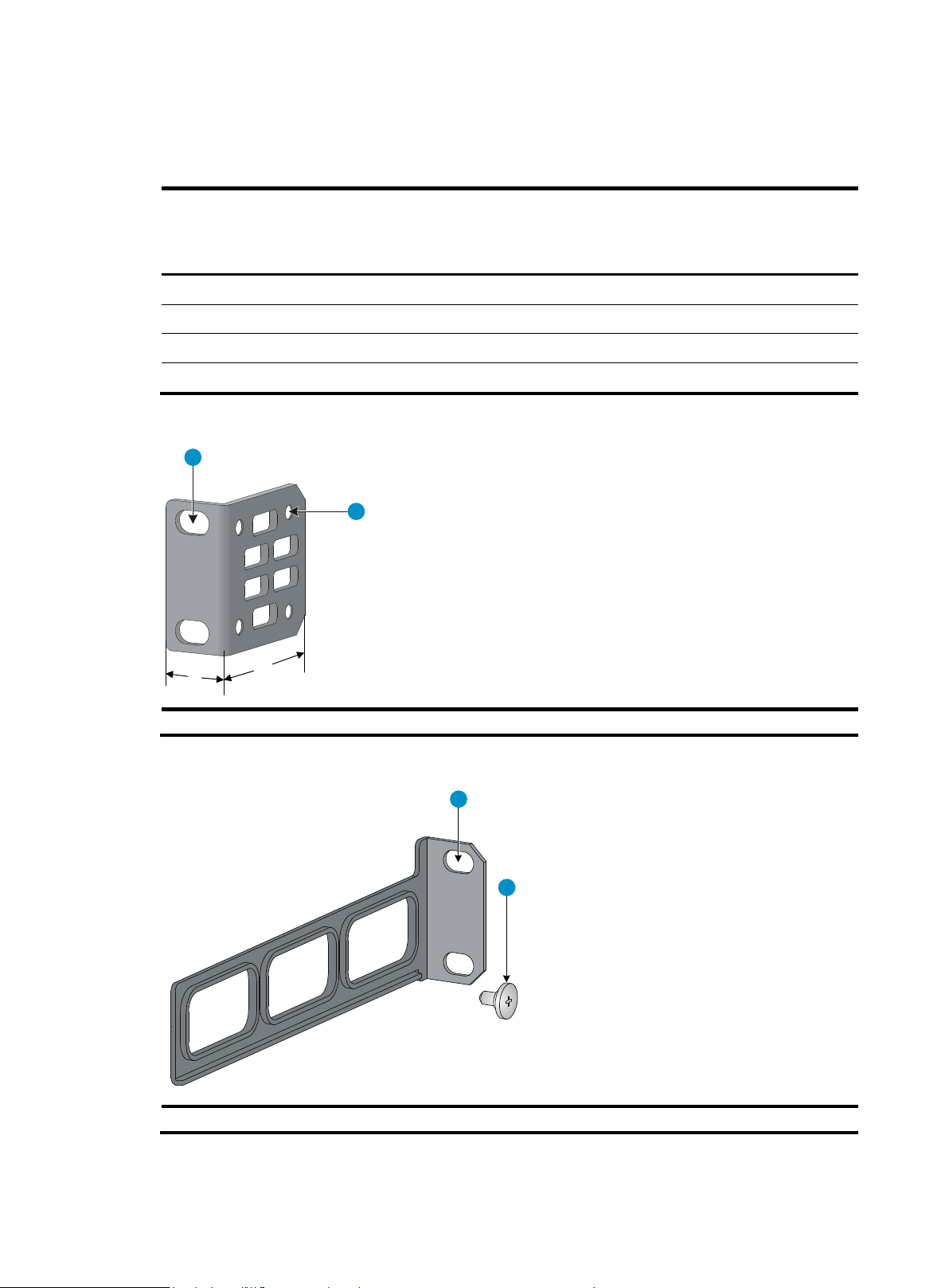
(1) Hole for attaching the bracket to a rack
(2) Hole for attaching the bracket to the switch chassis
(1) Hole for attaching the bracket to a rack
(2) Load-bearing screw
L1
L2
1
2
1
2
Mounting bracket kits
Table 6 Mounting bracket kits for the HPE 5510 HI switches
Figure 4 Front mounting bracket kit
Figure 5 Rear mounting bracket kit and load-bearing screw
8
Rack-mounting by using front mounting brackets
This task requires two people.
To install the switch in a 19-inch rack by using the front mounting brackets:
1. Wear an ESD wrist strap and make sure it makes good skin contact and is reliably grounded.
2. Determine the mounting position on the switch for the front mounting brackets.
You can install the front mounting brackets at one of the following positions:
HPE 5510 24G SFP 4SFP+ HI, HPE 5510 24G 4SFP+ HI, and HPE 5510 48G 4SFP+ HI
switches—Port side, power supply side, or mid-mounting position.
HPE 5510 24G PoE+ 4SFP+ HI and HPE 5510 48G PoE+ 4SFP+ HI switches—Mid-mounting
position.
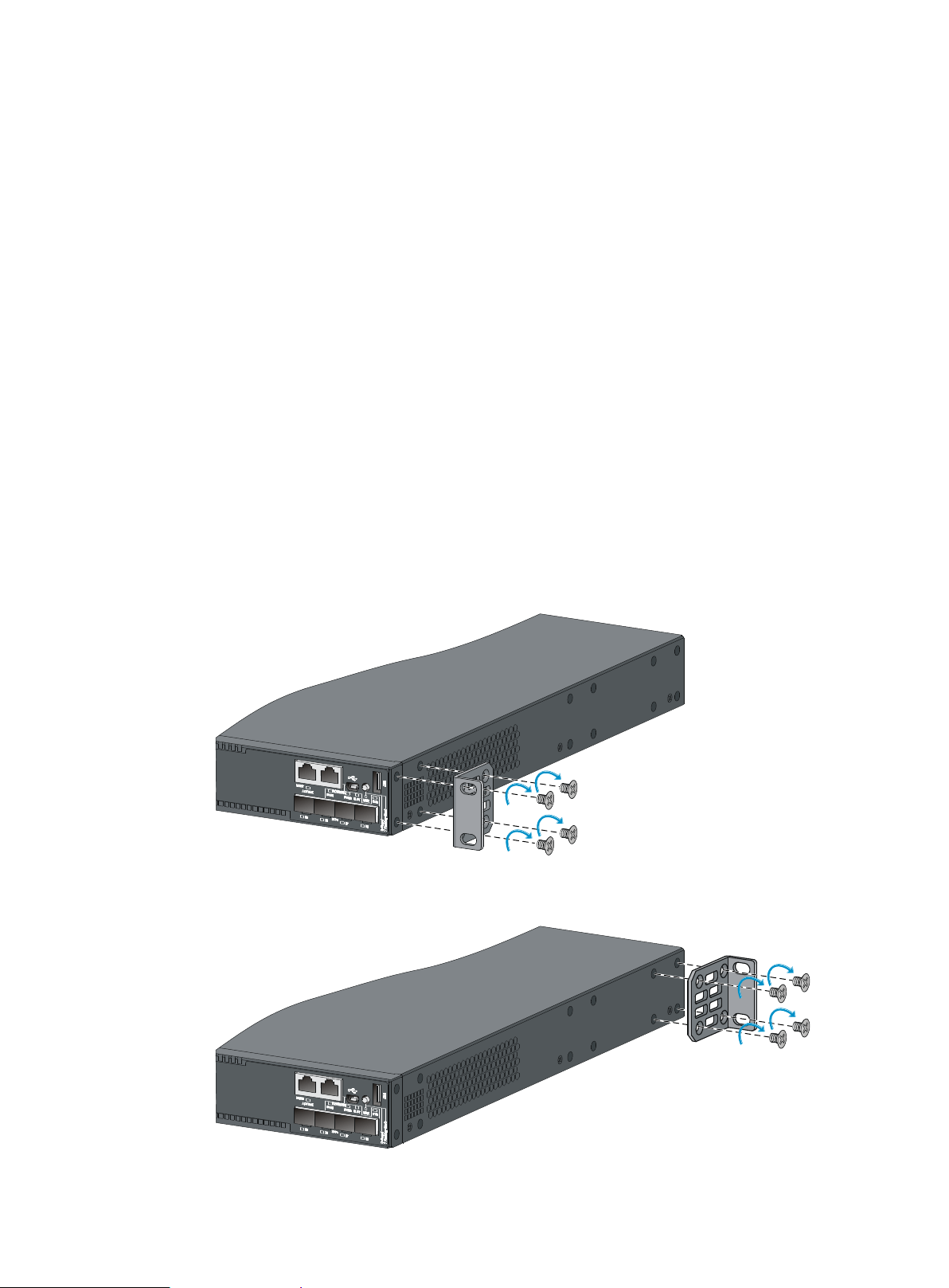
3. Attach the front mounting brackets to the chassis:
a. Unpack the front mounting brackets and the M4 screws (supplied with the switch) for attaching
the brackets to the switch chassis.
b. Align the round holes in the wide flange of one front mounting bracket with the screw holes in
the chassis.
c. Use M4 screws to attach the mounting bracket to the chassis.
d. Repeat the proceeding two steps to attach the other mounting bracket to the chassis.
Figure 6 Attaching the front mounting bracket to the port side
Figure 7 Attaching the front mounting bracket to the power supply side
9
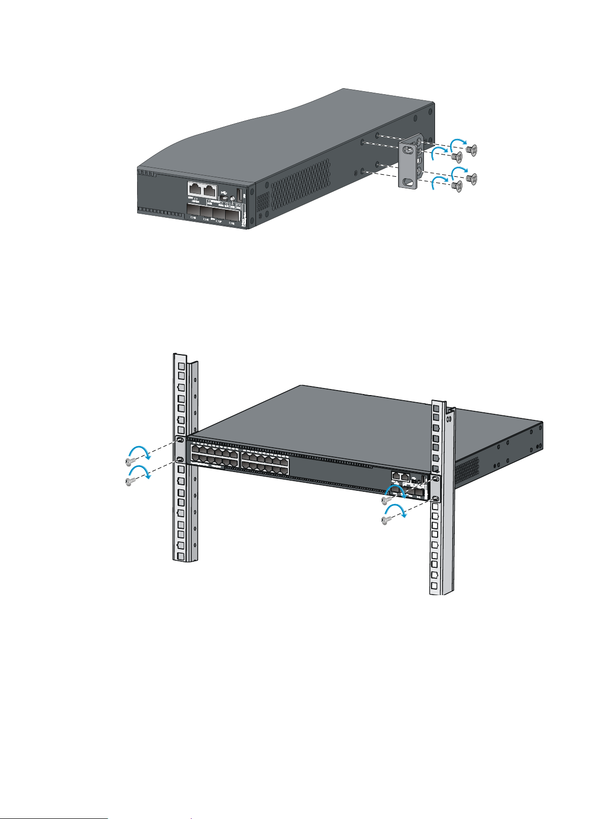
Figure 8 Attaching the front mounting bracket to the mid-mounting position
4. Mount the chassis in the rack:
a. One person supports the chassis bottom with one hand, holds the front part of the chassis with
the other hand, and pushes the chassis into the rack gently
b. The other person uses M6 screws and cage nuts (user supplied) to attach the switch to the rack.
Figure 9 Mounting the switch in the rack (front mounting brackets at the port side)
10
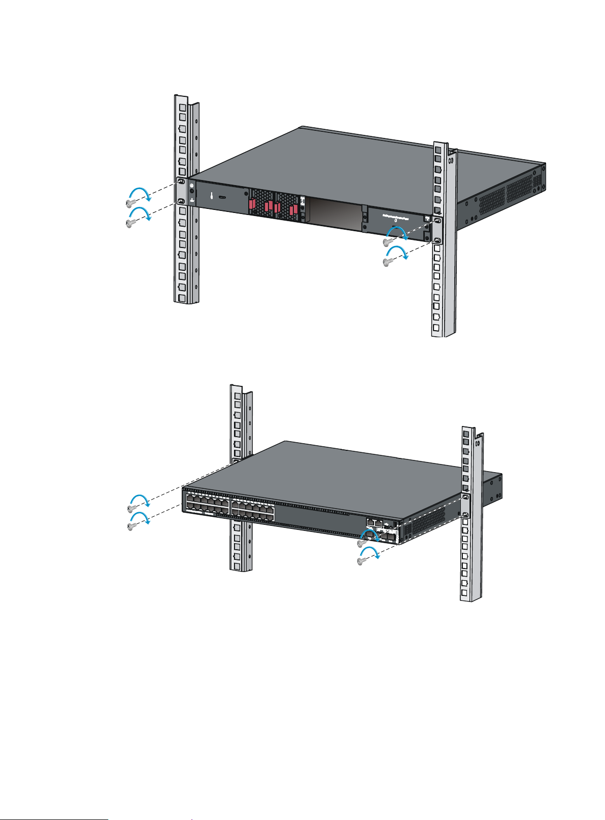
Figure 10 Mounting the switch in the rack (front mounting brackets at the power supply side)
Figure 11 Mounting the switch in the rack (front mounting brackets at the mid-mounting position)
Rack-mounting by using front and rear mounting brackets (HPE
5510 24G PoE+ 4SFP+ HI and HPE 5510 48G PoE+ 4SFP+
HI)
This mounting method is applicable to only the HPE 5510 24G PoE+ 4SFP+ HI and HPE 5510 48G PoE+
4SFP+ HI switches. You can install the front mounting brackets at the port-side or power-side mounting
11
position as needed. The following takes port-side mounting as an example. The power-side mounting is
similar.
This task requires two people.
To install the switch in a 19-inch rack by using the front and rear mounting brackets:
1. Wear an ESD wrist strap and make sure it makes good skin contact and is reliably grounded.
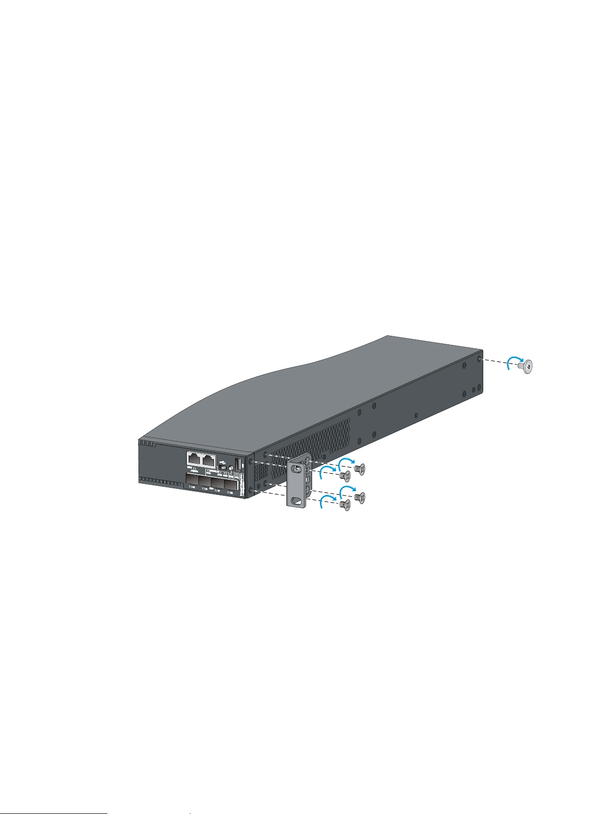
2. Attach the front mounting brackets and load-bearing screws to the chassis:
a. Unpack the front mounting brackets and the M4 screws for attaching the brackets to the switch
chassis.
b. Align the round holes in the wide flange of one front mounting bracket with the screw holes in
the port-side mounting position on one side of the chassis (see Figure 12).
c. Use M4 screws (supplied with the switch) to attach the mounting bracket to the chassis.
d. Repeat the proceeding two steps to attach the other mounting bracket to the chassis.
e. Unpack the load-bearing screws.
f. Install the load-bearing screws in one of the load-bearing screw mounting positions on both
sides of the chassis (see Figure 12).
Figure 12 Attaching the front mounting brackets and load-bearing screws to the chassis
3. Attach the rear mounting brackets to the rack:
a. Unpack the rear mounting brackets.
b. Install cage nuts (user-supplied) in the mounting holes in the rear rack posts.
c. Attach the rear mounting brackets to the rear posts with M6 screws (user supplied), as shown
in Figure 13.
12
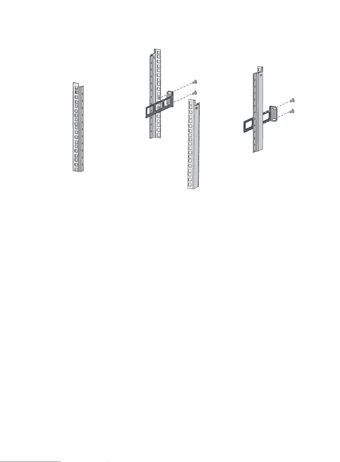
Figure 13 Attaching the rear mounting brackets to a rack
4. Mount the switch chassis in the rack:
a. One person supports the chassis bottom with one hand, holds the front part of the chassis with
the other hand, and pushes the chassis into the rack gently.
Make sure the load-bearing screws closely contact with the upper edges of the rear mounting
brackets, as shown in Figure 14.
b. The other person aligns the oval holes in the front brackets with the mounting holes in the front
rack posts, and attaches the front mounting brackets with M6 screws (user supplied) to the front
rack posts.
Make sure the front and rear mounting brackets have securely attached the switch to the rack.
13
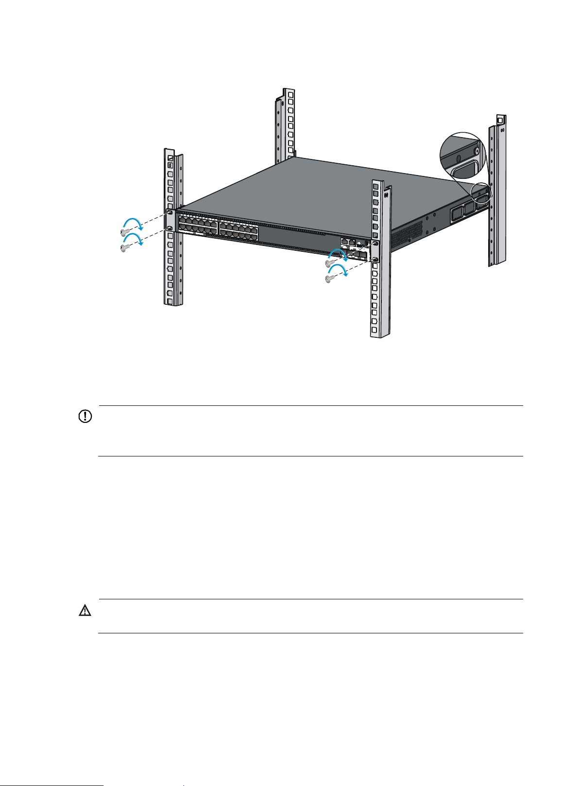
IMPORTANT:
Ensure good ventilation and 10 cm (3.9 in) of clearance around the chassis for heat dissipation.
Avoid placing heavy objects on the switch.
WARNING!
Correctly connecting the switch grounding cable is crucial to lightning protection and EMI protection.
Figure 14 Mounting the switch in the rack
Mounting the switch on a workbench
To mount the switch on a workbench:
1. Verify that the workbench is sturdy and reliably grounded.
2. Place the switch with bottom up, and clean the round holes in the chassis bottom with dry cloth.
3. Attach the rubber feet to the four round holes in the chassis bottom.
4. Place the switch with upside up on the workbench.
Grounding the switch
The power input end of the switch has a noise filter, whose central ground is directly connected to the
chassis to form the chassis ground (commonly known as PGND). You must securely connect this chassis
ground to the earth so the faradism and leakage electricity can be safely released to the earth to
minimize EMI susceptibility of the switch.
14
NOTE:
The power and grounding terminals in this section are for illustration only.
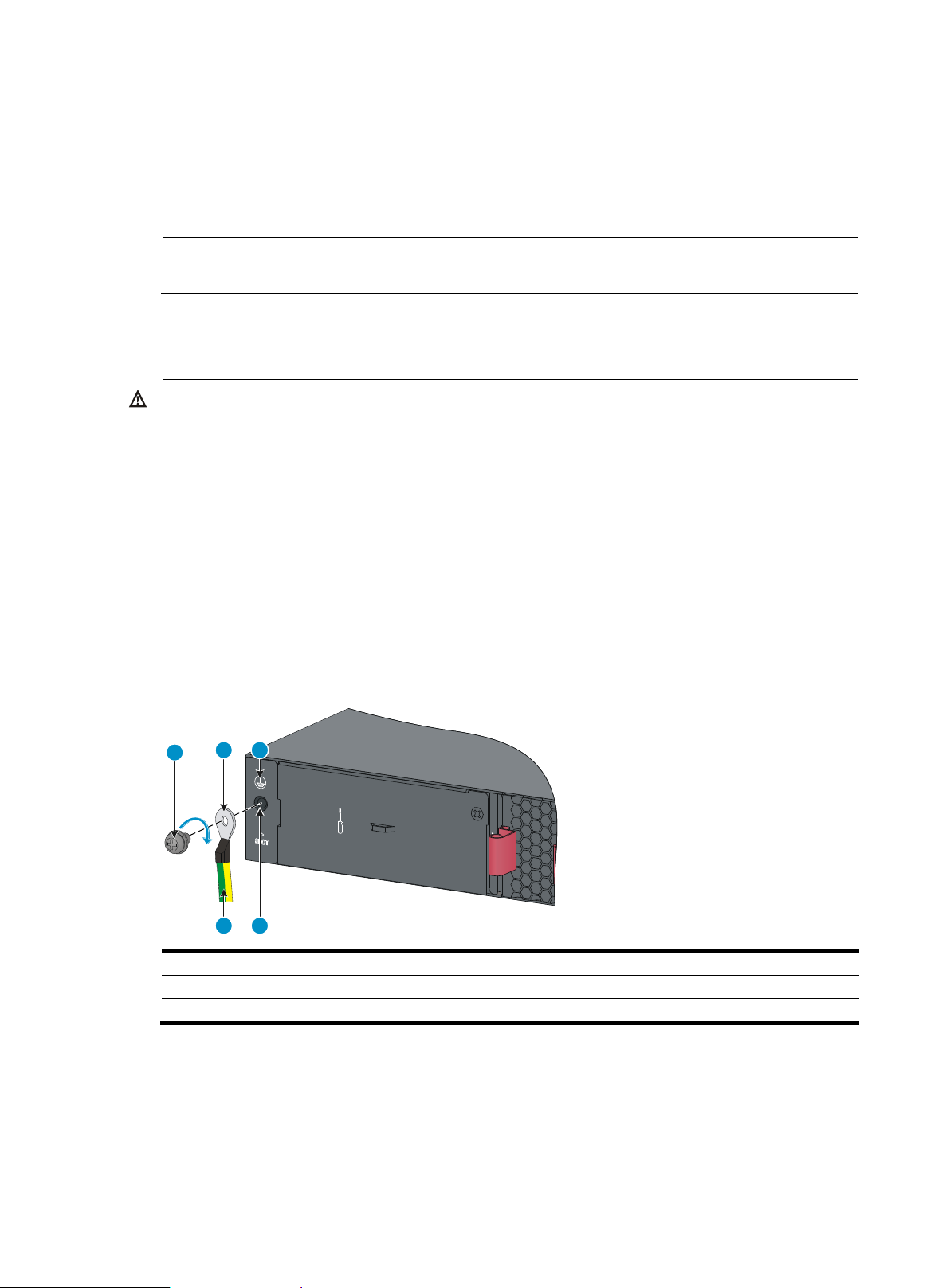
WARNING!
Connect the grounding cable to the grounding system in the equipment room. Do not connect it to a fire
main or lightning rod.
(1) Grounding screw
(2) Ring terminal
(3) Grounding sign
(4) Grounding hole
(5) Grounding cable
1
3
4
2
5
You can ground the switch in one of the following ways, depending on the grounding conditions
available at the installation site:
Grounding the switch with a grounding strip
Grounding the switch with a grounding conductor buried in the earth ground
Grounding the switch by using the AC power cord
Grounding the switch with a grounding strip
If a grounding strip is available at the installation site, connect the grounding cable to the grounding
strip.
Connecting the grounding cable to the chassis
1. Remove the grounding screw from the rear panel of the switch chassis.
2. Use the grounding screw to attach the ring terminal of the grounding cable to the grounding screw
hole.
3. Verify that the grounding cable has been securely connected to the rear grounding point.
Figure 15 Connecting the grounding cable to the chassis
Connecting the grounding cable to a grounding strip (for the HPE 5510 24G PoE+ 4SFP+ HI and HPE
5510 48G PoE+ 4SFP+ HI switches)
1. Remove the hex nut of a grounding post on the grounding strip.
2. Cut the grounding cable to a length required for connecting to the grounding strip.
3. Attach a ring terminal to the grounding cable:
15

(1) Grounding post
(2) Grounding strip
(3) Grounding cable
(4) Hex nut
1
4
3
2
a. Use a wire stripper to strip 5 mm (0.20 in) of insulation off the end of the grounding cable.
b. Slide the heat-shrink tubing onto the cable and insert the bare metal part into the end of the ring
terminal.
c. Use a crimper to secure the metal part of the cable to the ring terminal.
d. Slide the heat-shrink tubing down the cable until the tube covers the joint.
e. Use a blow dryer to shrink the tubing around the cable.
Figure 16 Attaching a ring terminal to the grounding cable
4. Connect the ring terminal to the grounding post of the grounding strip, and fasten it with the
removed hex nut.
Figure 17 Connecting the grounding cable to a grounding strip
Connecting the grounding cable to a grounding strip (for the HPE 5510 24G 4SFP+ HI, HPE 5510 48G
4SFP+ HI, and HPE 5510 24G SFP 4SFP+ HI switches)
1. Remove the hex nut of a grounding post on the grounding strip.
2. Cut the grounding cable to a length required for connecting to the grounding strip.
3. Use a wire stripper to peel 20 mm (0.79 in) of insulation sheath off the grounding cable end.
4. Use the needle-nose pliers to bend the bare wire.
5. Hook the grounding cable to the post on the grounding strip, and use the hex nut to secure the
cable to the post.
16
(1) Grounding post
(2) Grounding strip
(3) Grounding cable
(4) Hex nut
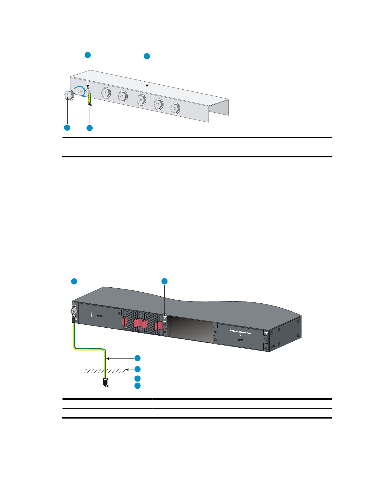
(1) Grounding screw
(2) Chassis rear panel
(3) Grounding cable
(4) Earth
(5) Joint
(6) Grounding conductor
1
2
3
4
1
2
3
4
5
6
Figure 18 Connecting the grounding cable to a grounding strip
Grounding the switch with a grounding conductor buried in the
earth ground
If the installation site has no grounding strips, but earth ground is available, hammer a 0.5 m (1.64 ft) or
longer angle iron or steel tube into the earth ground to serve as a grounding conductor.
The dimensions of the angle iron must be a minimum of 50 × 50 × 5 mm (1.97 × 1.97 × 0.20 in). The
steel tube must be zinc-coated and its wall thickness must be a minimum of 3.5 mm (0.14 in).
Weld the yellow-green grounding cable to the angel iron or steel tube and treat the joint for corrosion
protection.
Figure 19 Grounding the switch by burying the grounding conductor into the earth ground
17
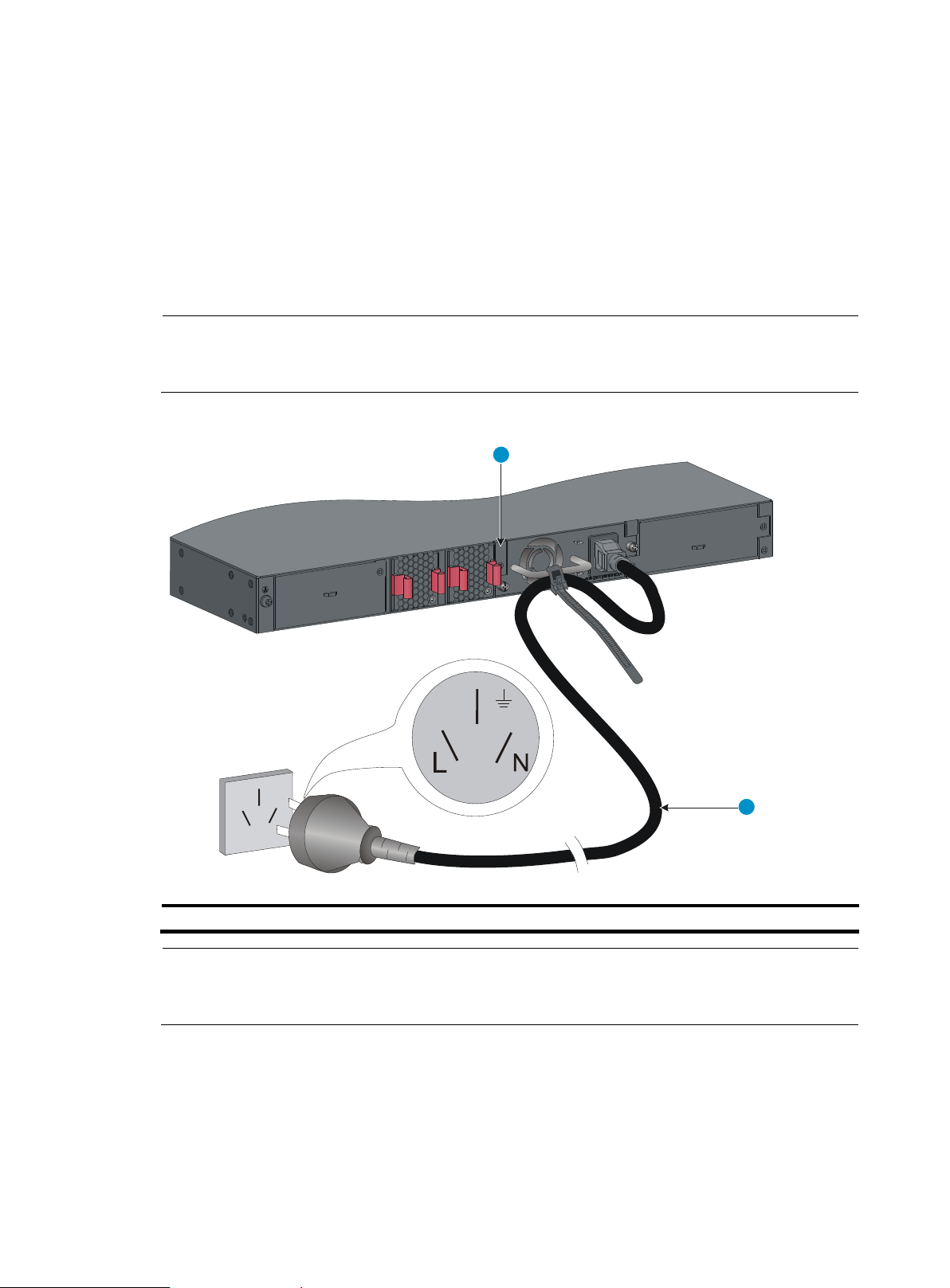
NOTE:
If the ground contact in the power outlet is not connected to the ground, report the problem and reconstruct
the grounding system.
(1) Chassis rear panel
(2) Three-wire AC power cord
NOTE:
To guarantee the grounding effect, use the grounding cable provided with the switch to connect to the
grounding strip in the equipment room as long as possible.
2
1
Grounding the switch by using the AC power cord
If the installation site has no grounding strips or earth ground, you ground an AC-powered switch through
the PE wire of the power cord. Make sure:
The power cord has a PE terminal.
The ground contact in the power outlet is securely connected to the ground in the power distribution
room or on the AC transformer side.
The power cord is securely connected to the power outlet.
Figure 20 Grounding through the PE wire of the AC power cord
18
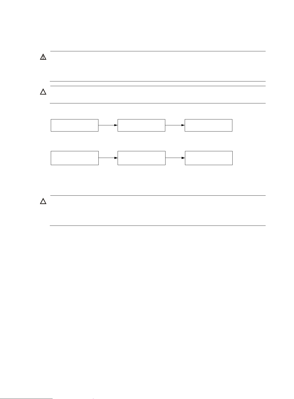
WARNING!
In power redundancy mode, you can replace a power supply without powering off the switch but you must
strictly follow the installation and procedures in Figure 21 and Figure 22 to avoid any bodily injury or
damage to the switch.
CAUTION:
Provide a circuit breaker for each power supply.
CAUTION:
To prevent damage to the power supply or the connectors on the backplane, insert the power supply
gently. If you encounter a hard resistance while inserting the power supply, pull out the power supply and
insert it again.
Install the power
supply
Connect the power
cord
Turn on the circuit
breaker
Turn off the circuit
breaker
Disconnect the power
cord
Remove the power
supply
Installing/removing a power supply
Figure 21 Installation procedure
Figure 22 Removal procedure
Installing a PSR150 power supply
For the PSR150-A1 and PSR150-D1 power supplies, the installation and removal procedures are the
same. The following takes the PSR150-A1 power supply as an example.
To install a power supply:
1. Wear an ESD wrist strap and make sure it makes good skin contact and is reliably grounded.
2. Unpack the power supply and verify that the power supply model is correct.
3. Correctly orient the power supply with the power supply slot (use the letters on the power supply
faceplate for orientation), grasp the handle of the power supply with one hand and support its
bottom with the other, and slide the power supply slowly along the guide rails into the slot (see
callout 1 in Figure 23).
4. Fasten the captive screws on the power supply with a Phillips screwdriver to secure the power
supply in the chassis (see callout 2 in Figure 23). If the captive screw cannot be tightly fastened,
verify the installation of the power supply.
5. Install the filler panel over the empty power supply slot to prevent dust and ensure good ventilation
if you install only one power supply.
19
 Loading...