

Page 1

HP 5500 EI & 5500 SI Switch Series
Installation Guide
Part number: 5998-1710
Document version: 6W101-20130630
Page 2

Legal and notice information
© Copyright 2011-2013 Hewlett-Packard Development Company, L.P.
No part of this documentation may be reproduced or transmitted in any form or by any means without
prior written consent of Hewlett-Packard Development Company, L.P.
The information contained herein is subject to change without notice.
HEWLETT-PACKARD COMPANY MAKES NO WARRANTY OF ANY KIND WITH REGARD TO THIS
MATERIAL, INCLUDING, BUT NOT LIMITED TO, THE IMPLIED WARRANTIES OF MERCHANTABILITY
AND FITNESS FOR A PARTICULAR PURPOSE. Hewlett-Packard shall not be liable for errors contained
herein or for incidental or consequential damages in connection with the furnishing, performance, or
use of this material.
The only warranties for HP products and services are set forth in the express warranty statements
accompanying such products and services. Nothing herein should be construed as constituting an
additional warranty. HP shall not be liable for technical or editorial errors or omissions contained
herein.
Page 3

Contents
Preparing for installation ············································································································································· 1
Safety recommendations ·················································································································································· 1
Examining the installation site ········································································································································· 1
Temperature/humidity ············································································································································· 1
Cleanness ·································································································································································· 2
EMI ············································································································································································· 2
Laser safety ································································································································································ 2
Installation tools ································································································································································· 3
Installing the switch ······················································································································································ 4
Installing the switch in a 19-inch rack ····························································································································· 5
Mounting brackets ···················································································································································· 6
Rack-mounting by using only front mounting brackets ························································································· 7
Rack-mounting by using front mounting brackets and a rack shelf ····································································· 8
Rack-mounting by using front and rear mounting brackets ·················································································· 9
Mounting the switch on a workbench ·························································································································· 12
Grounding the switch ···················································································································································· 12
Grounding the switch with a grounding strip ····································································································· 13
Grounding the switch with a grounding conductor buried in the earth ground ············································· 15
Grounding the switch by using the AC power cord ·························································································· 16
Installing/removing a power supply ···························································································································· 16
Installing a power supply ····································································································································· 16
Removing a power supply ···································································································································· 17
Connecting the power cord ·········································································································································· 18
Connecting the AC power cord ··························································································································· 18
Connecting the PSR150-D/PSR150-D1 to a –48 VDC power source ····························································· 19
Connect the switch to a +12 VDC output RPS ··································································································· 20
Connecting the switch to a –52 to –55 VDC output RPS ·················································································· 20
Installing/removing an interface card ························································································································· 21
Installing an interface card ··································································································································· 21
Removing an interface card ································································································································· 22
Installing/removing a dedicated CX4/SFP+ cable ··························································································· 23
Verifying the installation ················································································································································ 23
Accessing the switch for the first time ······················································································································· 24
Setting up the configuration environment ···················································································································· 24
Connecting the console cable ······································································································································ 24
Console cable ························································································································································ 24
Connection procedure ·········································································································································· 24
Setting terminal parameters ·········································································································································· 25
i
Page 4

Powering on the switch·················································································································································· 28
Setting up an IRF fabric ············································································································································· 29
IRF fabric setup flowchart ·············································································································································· 29
Planning IRF fabric setup ··············································································································································· 30
Planning IRF fabric size and the installation site ································································································ 30
Identifying the master switch and planning IRF member IDs ············································································ 30
Planning IRF topology and connections ·············································································································· 31
Identifying physical IRF ports on the member switches ····················································································· 32
Planning the cabling scheme ······························································································································· 32
Configuring basic IRF settings ······································································································································· 33
Connecting the physical IRF ports ································································································································ 34
Accessing the IRF fabric to verify the configuration ··································································································· 34
Maintenance and troubleshooting ···························································································································· 35
Power supply failure ······················································································································································ 35
Built-in power supply failure ································································································································· 35
Hot swappable power supply failure ·················································································································· 36
Fan failure ······································································································································································· 36
Configuration terminal problems ·································································································································· 37
Appendix A Chassis views and technical specifications ························································································ 38
Chassis views ································································································································································· 39
5500-24G EI (2 slots)/5500-24G EI TAA (2 slots)/5500-24G SI (2 slots) ··················································· 39
5500-48G EI (2 slots)/5500-48G EI TAA (2 slots)/5500-48G SI (2 slots) ··················································· 40
5500-24G-SFP EI (2 slots)/5500-24G-SFP EI TAA (2 slots) ············································································· 41
5500-24G-PoE+ EI (2 slots)/5500-24G-PoE+ EI TAA (2 slots)/5500-24G-PoE+ SI (2 slots) ······················ 42
5500-48G-PoE+ EI (2 slots)/5500-48G-PoE+ EI TAA (2 slots)/5500-48G-PoE+ SI (2 slots) ······················ 43
Technical specifications ················································································································································· 43
Chassis dimensions and weights ························································································································· 43
Ports and interface card slots ······························································································································· 44
Environmental specifications ········································································································································· 45
Power specifications ······················································································································································ 45
Power input types ·················································································································································· 45
AC input voltage specifications ··························································································································· 45
RPS DC input voltage specifications and RPS compatibility ············································································· 46
Power consumption specifications for non-PoE switches ··················································································· 46
Power consumption specifications for PoE switches ·························································································· 46
Cooling system ······················································································································································ 47
Appendix B FRUs and compatibility matrixes ·········································································································· 48
Hot swappable power supplies ···································································································································· 48
Interface cards ································································································································································ 48
SFP/SFP+/XFP transceiver modules and SFP+/CX4 cables ····················································································· 49
GE SFP transceiver modules ································································································································· 50
FE SFP transceiver modules ·································································································································· 50
ii
Page 5

10-GE SFP+ transceiver modules ························································································································· 51
SFP+ cables ···························································································································································· 52
10-GE XFP transceiver modules ··························································································································· 52
CX4 cables ····························································································································································· 53
Appendix C Ports and LEDs ······································································································································ 54
Ports ················································································································································································· 54
Console port ·························································································································································· 54
10/100/1000Base-T Ethernet port ···················································································································· 54
SFP port ·································································································································································· 54
Combo interface ···················································································································································· 55
LEDs ················································································································································································· 55
System status LED··················································································································································· 56
Power supply status LEDs ······································································································································ 56
RPS status LED ························································································································································ 56
Port mode LED ························································································································································ 57
Seven-segment LED ················································································································································ 57
10/100/1000Base-T Ethernet port LED ············································································································· 58
SFP port status LED ················································································································································ 59
Interface card status LED ······································································································································· 60
Support and other resources ····································································································································· 61
Contacting HP ································································································································································ 61
Subscription service ·············································································································································· 61
Related information ························································································································································ 61
Documents ······························································································································································ 61
Websites ································································································································································· 61
Conventions ···································································································································································· 62
Index ··········································································································································································· 64
iii
Page 6

Preparing for installation
Safety recommendations
To avoid any equipment damage or bodily injury caused by improper use, read the following safety
recommendations before installation. Note that the recommendations do not cover every possible
hazardous condition.
• Before cleaning the switch, unplug all power cords. Do not clean the switch with wet cloth or liquid.
• Do not place the switch near water or in a damp environment. Prevent water or moisture from
entering the switch chassis.
• Do not place the switch on an unstable case or desk. The switch might be severely damaged in case
of a fall.
• Ensure proper ventilation of the equipment room and keep the air inlet and outlet vents of the switch
free of obstruction.
• Make sure the operating voltage is in the required range.
• To avoid electrical shocks, do not open the chassis while the switch is operating or when the switch
is just powered off.
• When replacing FRUs, wear an ESD-preventive wrist strap to avoid damaging the units.
Examining the installation site
The 5500 EI and 5500 SI switches must be used indoors. You can mount your switch in a rack or on a
workbench, but make sure:
• Adequate clearance is reserved at the air inlet and exhaust vents for ventilation.
• The rack or workbench has a good ventilation system.
• The rack is sturdy enough to support the switch and its accessories.
• The rack or workbench is well earthed.
To ensure normal operation and long service life of your switch, install it in an environment that meets the
requirements described in the following subsections.
Temperature/humidity
Maintain appropriate temperature and humidity in the equipment room.
• Lasting high relative humidity can cause poor insulation, electricity creepage, mechanical property
change of materials, and metal corrosion.
• Lasting low relative humidity can cause washer contraction and ESD and bring problems including
loose captive screws and circuit failure.
• High temperature can accelerate the aging of insulation materials and significantly lower the
reliability and lifespan of the switch.
For the temperature and humidity requirements, see "Environmental specifications."
1
Page 7

p
g
W
g
Cleanness
Dust buildup on the chassis may result in electrostatic adsorption, which causes poor contact of metal
components and contact points, especially when indoor relative humidity is low. In the worst case,
electrostatic adsorption can cause communication failure.
Table 1 Dust concentration limit in the equipment room
EMI
Substance Concentration limit (
Dust
NOTE:
Dust diameter ≥ 5 μm
≤ 3 x 10⁴ (no visible dust on the tabletop over three days)
articles/m³)
The equipment room must also meet strict limits on salts, acids, and sulfides to eliminate corrosion and
premature aging of components, as shown in Table 2.
Table 2 Harmful gas li
Gas Maximum concentration (m
SO
2
H2S 0.006
NH3 0.05
Cl2 0.01
mits in the equipment room
/m3)
0.2
All electromagnetic interference (EMI) sources, from outside or inside of the switch and application
system, adversely affect the switch in a conduction pattern of capacitance coupling, inductance coupling,
electromagnetic wave radiation, or common impedance (including the grounding system) coupling. To
prevent EMI, take the following actions:
• If AC power is used, use a single-phase three-wire power receptacle with protection earth (PE) to
filter interference from the power grid.
• Keep the switch far away from radio transmitting stations, radar stations, and high-frequency
devices.
• Use electromagnetic shielding, for example, shielded interface cables, when necessary.
• Route interface cables only indoors to prevent signal ports from getting damaged by overvoltage or
overcurrent caused by lightning strikes.
Laser safety
The 5500 EI and 5500 SI switches are Class 1 laser devices.
ARNING!
Do not stare into any fiber port when the switch has power. The laser li
may hurt your eyes.
ht emitted from the optical fiber
2
Page 8

Installation tools
• Flathead screwdriver
• Phillips screwdriver
• Needle-nose pliers
• Wire-stripping pliers
• Diagonal pliers
• ESD-preventive wrist strap
• Blow dryer
All these installation tools are user supplied.
3
Page 9
g
g
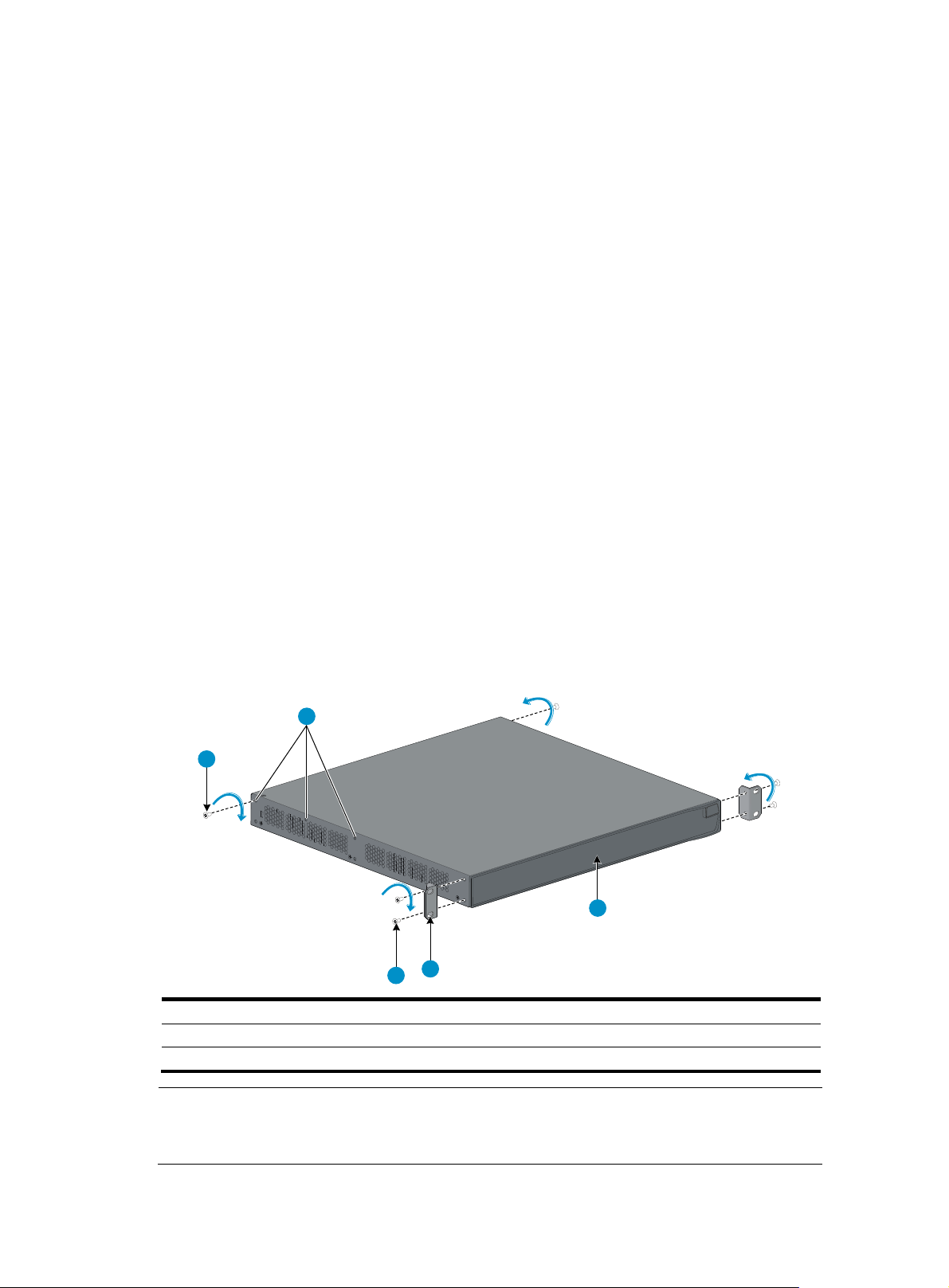
Installing the switch
CAUTION:
Keep the tamper-proof seal on a mountin
chassis, contact your local HP a
caused thereby.
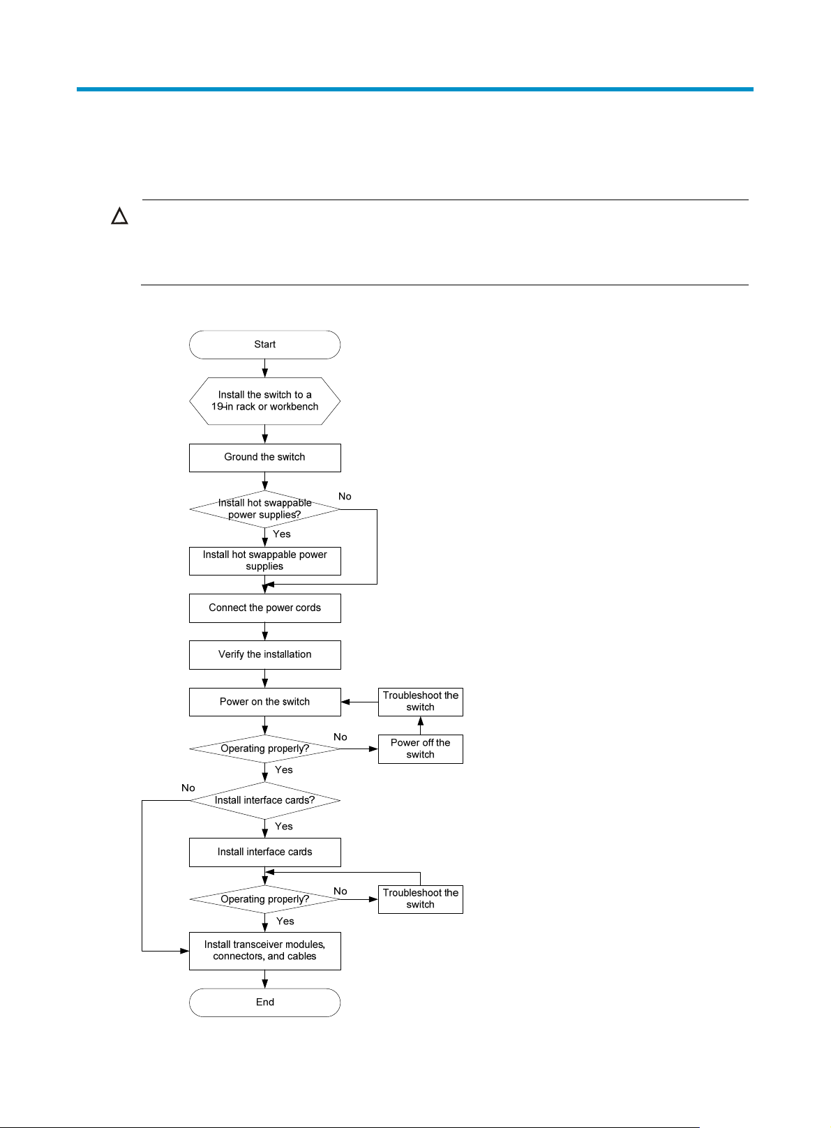
Figure 1 Hardware installation flow
ent for permission. Otherwise, HP shall not be liable for any consequence
screw on the chassis cover intact, and if you want to open the
4
Page 10

y
weight
Installing the switch in a 19-inch rack
You can install the switch in a 19-inch standard rack by using different mounting positions. Table 3 shows
the installation methods available for the switches of different depths.
Table 3 Installation methods
Use front
Chassis Depth
mounting
brackets
onl
5500-24G EI (2 slots)
5500-24G EI TAA (2 slots)
5500-24G SI (2 slots)
5500-48G EI (2 slots)
5500-48G EI TAA (2 slots)
5500-48G SI (2 slots)
5500-24G-SFP EI (2 slots)
5500-24G-SFP EI TAA (2 slots)
5500-24G-PoE+ EI (2 slots)
5500-24G-PoE+ EI TAA (2 slots)
5500-24G-PoE+ SI (2 slots)
5500-48G-PoE+ EI (2 slots)
5500-48G-PoE+ EI TAA (2 slots)
5500-48G-PoE+ SI (2 slots)
300 mm
(11.81 in)
360 mm
(14.17 in)
420 mm
(16.54 in)
Yes (see
"Rack-mounti
ng by using
only front
mounting
brac
kets"
No
No
Use front mounting
brackets and a rack
shelf
Yes (see
"Rack-mounting by
using front mounting
brackets and a rack
shelf")
Yes (see
"Rack-mounting by
using front mounting
brackets and a rack
shelf")
Yes (see
"Rack-mounting by
using front mounting
brackets and a rack
shelf")
Use front and
rear mounting
brackets
No
Yes (see
"Rack-mounting
by using front
and rear
mounting
brac
kets")
Yes (see
"Rack-mounting
by using front
and rear
mounting
brac
kets")
NOTE:
For a switch with a depth greater than 300 mm (11.81 in), the front mounting brackets are not
-bearing.
5
Page 11
g
Mounting brackets
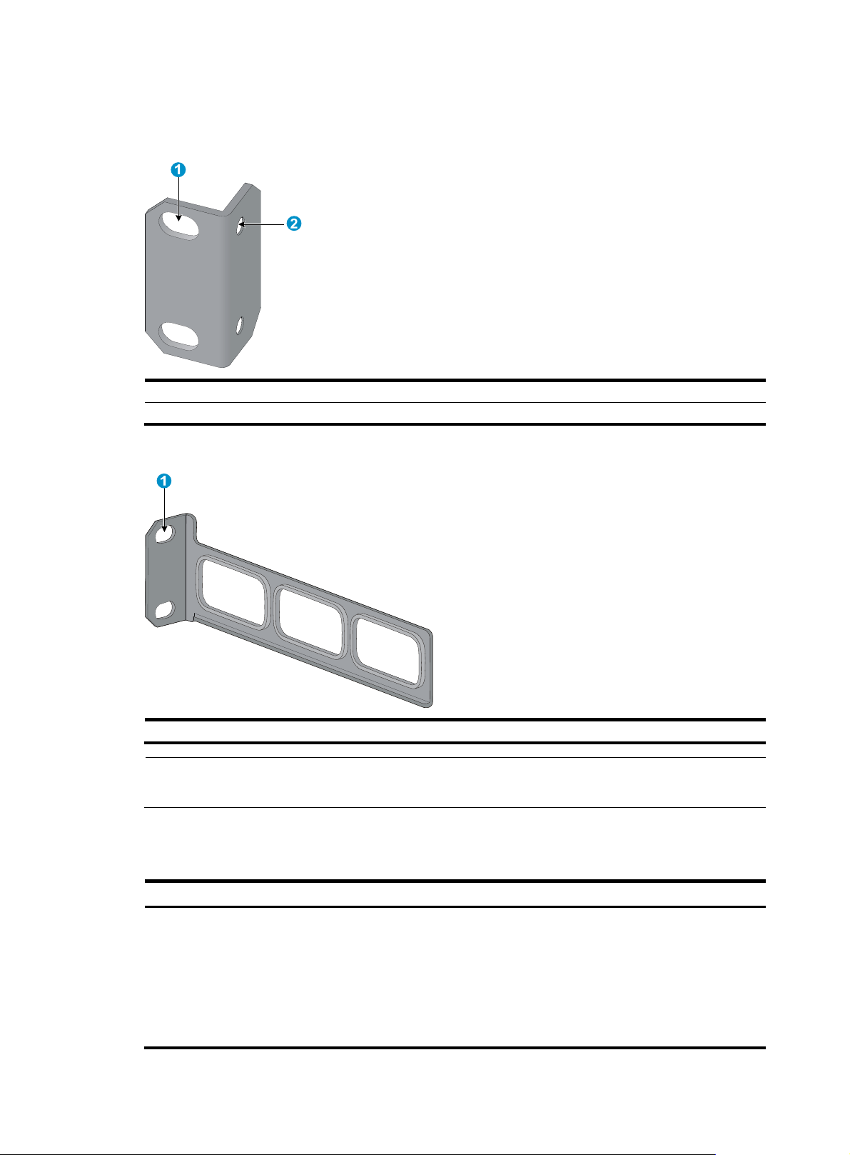
Figure 2 Front mounting bracket
(1) Hole for attaching to a rack (by using an M6 screw)
(2) Hole for attaching to the switch chassis
Figure 3 Rear mounting bracket
(1) Hole for attaching to a rack (by using an M6 screw)
NOTE:
The M6 screws for attaching the brackets to a rack are user supplied.
Table 4 shows the mounting bracket shipment for different switch models.
Table 4 Mounting bracket kit shipped with the 5500 EI and 5500 SI switches
Chassis Front mountin
5500-24G EI (2 slots)
5500-24G EI TAA (2 slots)
5500-48G EI (2 slots)
5500-48G EI TAA (2 slots)
5500-24G SI (2 slots)
5500-48G SI (2 slots)
One pair N/A
6
brackets
Rear mounting brackets
Page 12
Chassis Front mounting brackets
5500-24G-SFP EI (2 slots)
5500-24G-SFP EI TAA (2 slots)
5500-24G-PoE+ EI (2 slots)
5500-24G-PoE+ EI TAA (2 slots)
5500-48G-PoE+ EI (2 slots)
5500-48G-PoE+ EI TAA (2 slots)
5500-24G-PoE+ SI (2 slots)
5500-48G-PoE+ SI (2 slots)
One pair One pair
One pair One pair
Rear mounting brackets
Rack-mounting by using only front mounting brackets
This installation method is available only for the 5500-24G EI (2 slots), 5500-24G EI TAA (2 slots),
5500-48G EI (2 slots), 5500-48G EI TAA (2 slots), 5500-24G SI (2 slots), and 5500-48G SI (2 slots)
switches.
This task requires two persons.
To mount a switch in a 19-inch standard rack by using only the front mounting brackets:
1. Wear an ESD-preventive wrist strap and make sure it makes good skin contact and is well
grounded.
2. Verify that the rack is well grounded and can support the weight of the switch chassis and all its
accessories.
3. Unpack the front mounting brackets and the screws for attaching the brackets to the switch chassis.
4. Align the round holes in one bracket with the holes in the front mounting position of the switch
chassis, and use the screws to attach the mounting bracket to the chassis, as shown in Figure 4.
5. R
epeat the previous step to attach the other mounting bracket to the chassis.
Figure 4 Attaching the front mounting brackets to the chassis
(1) Front panel of the switch (2) Front mounting bracket
(3) Screw
6. Install cage nuts (user-supplied) in the mounting holes in the rack posts.
7
Page 13
7. One person holds the switch chassis and aligns the oval holes in the brackets with the mounting
holes in the rack posts, and the other person attaches the mounting brackets with M6 screws
(user-supplied) to the rack, as shown in Figure 5.
Figure 5 Attaching th
e front mounting brackets to the rack
1
4
3
1
2
(1) Front square-holed post (2) Front panel
(3) Screw for attaching the front mounting brackets to the square-holed
post
(4) Front mounting bracket
Rack-mounting by using front mounting brackets and a rack shelf
This installation method is available for all 5500 EI and 5500 SI switches.
To mount a switch in a 19-inch rack by using the front mounting brackets and a rack shelf:
1. Wear an ESD-preventive wrist strap and make sure it makes good skin contact and is well
grounded.
2. Verify that the rack is well grounded and can support the weight of the switch chassis and all its
accessories.
3. Attach the rack shelf horizontally in a proper position in the rack.
4. Unpack the front mounting brackets and the screws for attaching the brackets to the switch chassis.
5. Align the round holes in one bracket with the holes in the front mounting position of the switch
chassis, and use the removed screws to attach the mounting bracket to the chassis, as shown
in Figure 4.
epeat the previous step to attach the other mounting bracket to the chassis.
6. R
8
Page 14
weig
7. Install cage nuts (user-supplied) in the mounting holes in the rack posts.
8. Place the switch on the rack shelf, push it into the rack until the brackets touch the rack posts, and
attach the mounting brackets with M6 screws (user-supplied) to the rack, as shown in Figure 5.
Rack-mounting by using front and rear mounting brackets
This installation method is available only for the 5500-24G-PoE+ EI (2 slots), 5500-24G-PoE+ EI TAA (2
slots), 5500-48G-PoE+ EI (2 slots), 5500-48G-PoE+ EI TAA (2 slots), 5500-24G-PoE+ SI (2 slots),
5500-48G-PoE+ SI (2 slots), 5500-24G-SFP EI (2 slots), and 5500-24G-SFP EI TAA (2 slots) switches.
This task requires two persons.
To install the switch in a 19-inch rack by using the front and rear mounting brackets:
1. Wear an ESD-preventive wrist strap and make sure it makes good skin contact and is well
grounded.
2. Unpack the front mounting brackets and the screws for attaching the brackets to the switch chassis.
3. Align the round holes in one front mounting bracket with the holes in the front mounting position of
the switch chassis, and use the removed screws to attach the mounting bracket to the chassis, as
shown in Figure 4.
4. R
epeat the previous step to attach the other front mounting bracket to the chassis.
5. Unpack the rear mounting brackets and the load-bearing screws.
6. Attach the load-bearing screws in one of the rear mounting positions (see callout 2 in Figure 6) a
needed.
The 5500-24G-SFP EI (2 slots) and 5500-24G-SFP EI TAA (2 slots) switches have only two of the
rear mounting positions.
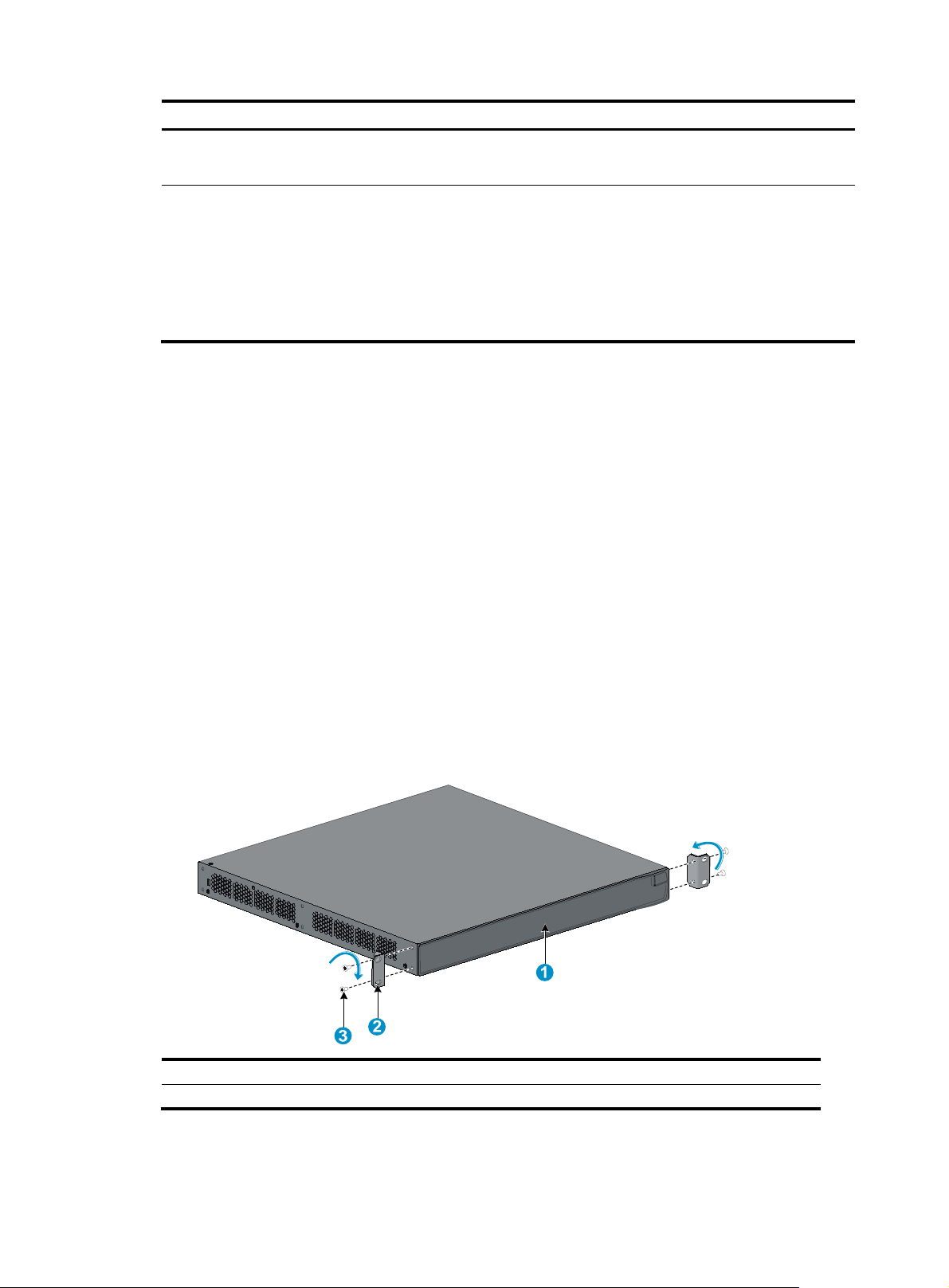
Figure 6 Attaching the front mounting brackets and load-bearing screws to the switch chassis
2
1
3
4
5
s
(1) Load-bearing screw (2) Rear mounting positions
(3) Front panel (4) Front mounting bracket
(5) Screw for attaching the front mounting brackets to the switch
NOTE:
The rear mounting brackets must closely contact with the load-bearing screws to support the chassis
ht.
9
Page 15
7. Install cage nuts (user-supplied) in the mounting holes in the front and rear rack posts.
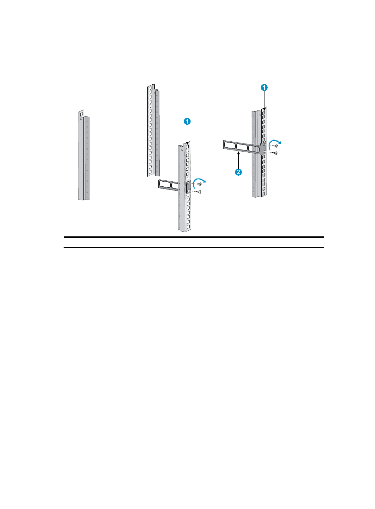
8. Attach the rear mounting brackets to the rear posts with M6 screws (user supplied), as shown
in Figure 7.
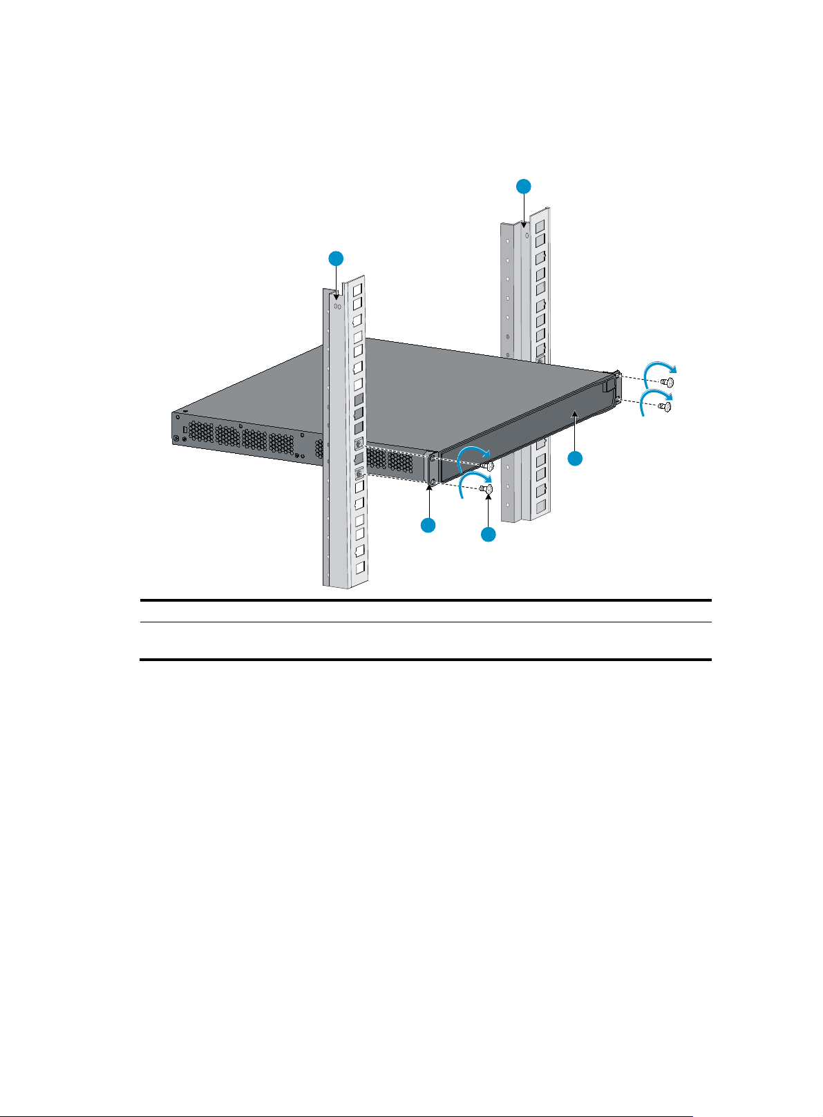
Figure 7 Attaching th
e rear mounting brackets to a rack
(1) Rear square-holed post (2) Rear mounting bracket
9. One person supports the chassis bottom with one hand, holds the front part of the chassis with the
other hand, and pushes the chassis into the rack gently.
Make sure the load-bearing screws closely contact with the upper edges of the rear mounting
brackets, as shown in Figure 8.
10
Page 16
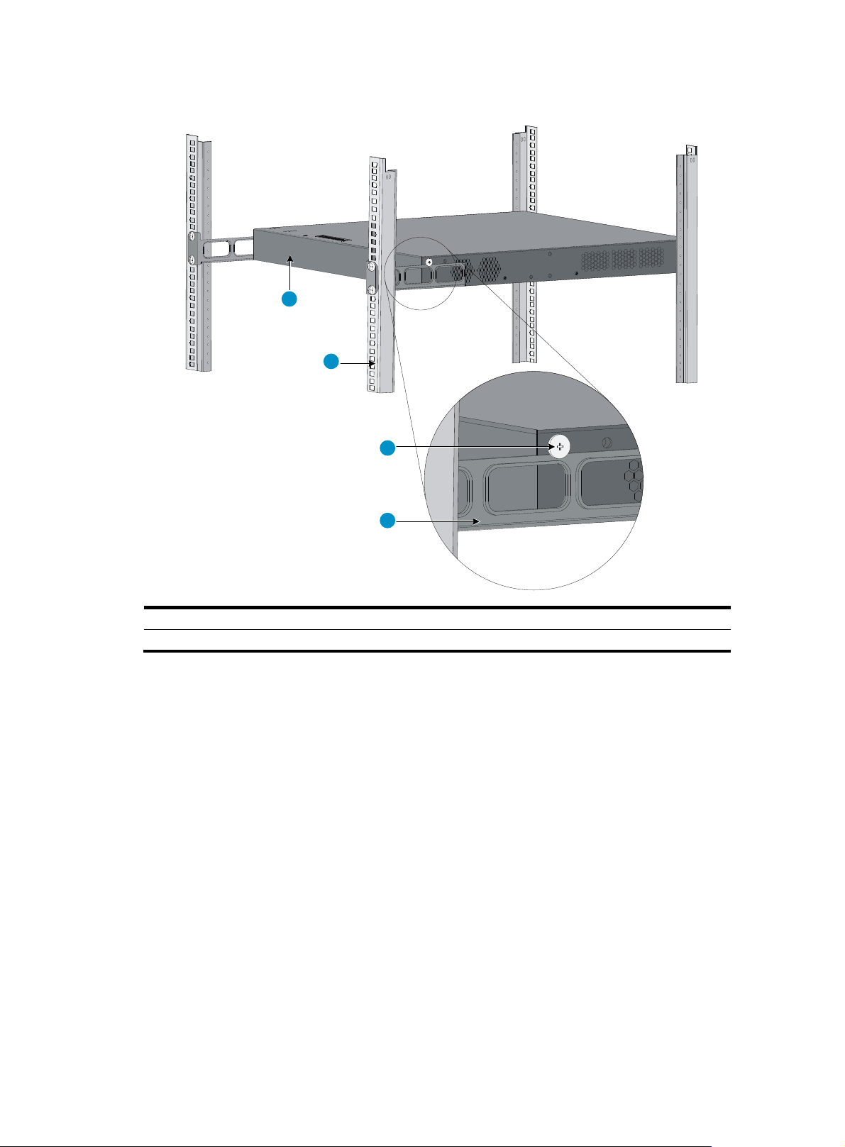
Figure 8 Mounting the switch in the rack
1
2
3
4
(1) Rear panel (2) Rear square-holed post
(3) Load-bearing screw (4) Rear mounting bracket
10. The other person aligns the oval holes in the front brackets with the mounting holes in the front rack
posts, and attaches the front mounting brackets with M6 screws (user supplied) to the front rack
posts, as shown in Figure 9.
Make sure the front and rear mou
nting brackets have securely attached the switch in the rack.
11
Page 17
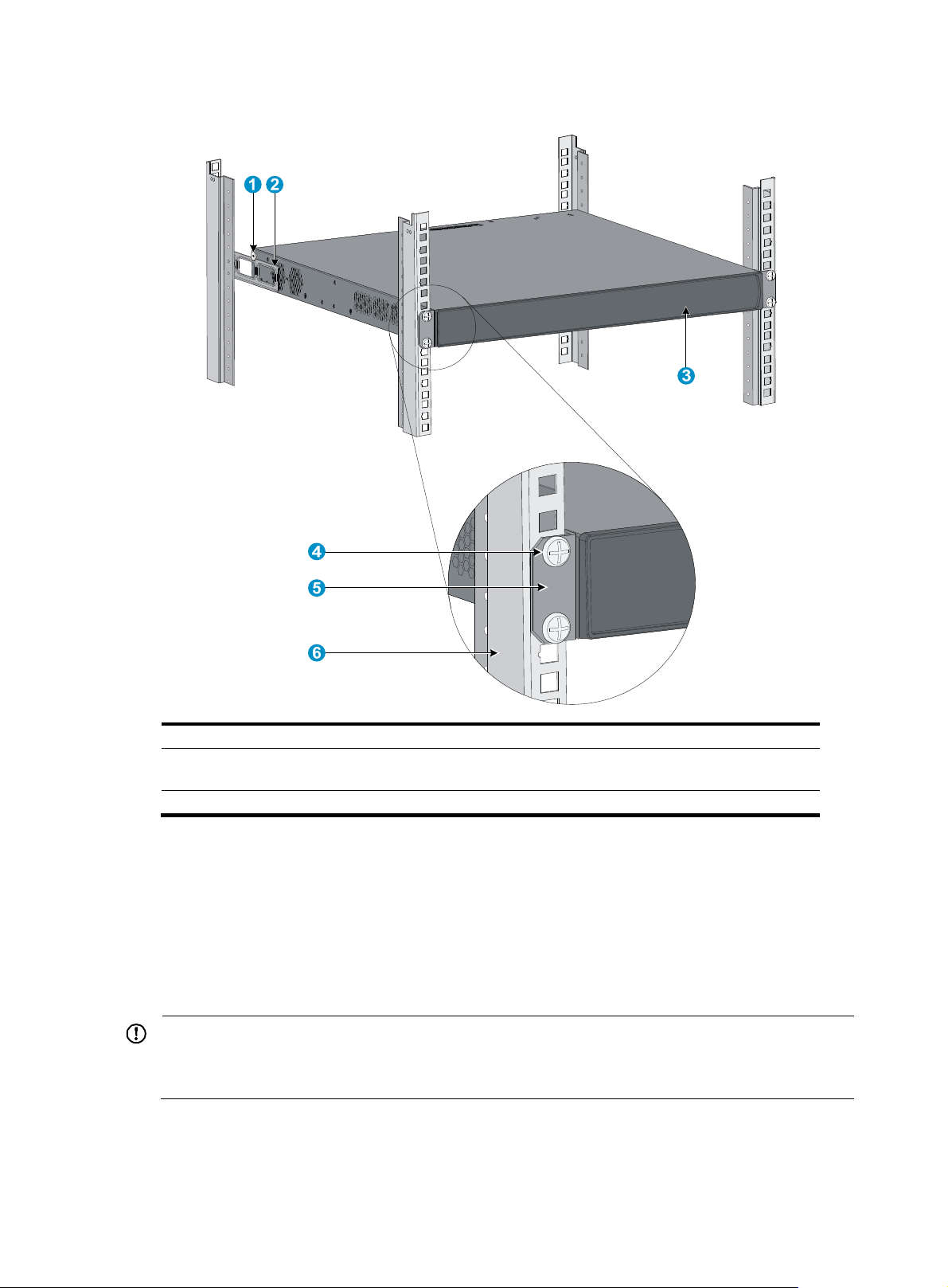
Figure 9 Attaching the front brackets to the rack
(1) Load-bearing screw (2) Rear mounting bracket
(3) Front panel (4) Screw used to attach front mounting brackets to front
brackets
(5) Front mounting bracket (6) Front square-holed post
Mounting the switch on a workbench
1. Verify that the workbench is sturdy and well grounded.
2. Place the switch with bottom up, and clean the round holes in the chassis bottom with dry cloth.
3. Attach the rubber feet to the four round holes in the chassis bottom.
4. Place the switch with upside up on the workbench.
IMPORTANT:
• Ensure good ventilation and 10 cm (3.9 in) of clearance around the chassis for heat dissipation.
• Avoid placing heavy objects on the switch.
Grounding the switch
12
Page 18

W
W
g
ARNING!
Correctly connecting the switch grounding cable is crucial to lightning protection and EMI protection.
The power and grounding terminals in this section are for illustration only.
The power input end of the switch has a noise filter, whose central ground is directly connected to the
chassis to form the chassis ground (commonly known as PGND). You must securely connect this chassis
ground to the earth so the faradism and leakage electricity can be safely released to the earth to
minimize EMI susceptibility of the switch.
You can ground the switch in one of the following ways, depending on the grounding conditions
available at the installation site:
• Grounding the switch with a grounding strip
• Grounding the switch with a grounding conductor buried in the earth ground
• Grounding the switch by using the AC power cord
Grounding the switch with a grounding strip
If a grounding strip is available at the installation site, connect the grounding cable to the grounding
strip.
ARNING!
Connect the
main or lightning rod.
CAUTION:
rounding cable to the grounding system in the equipment room. Do not connect it to a fire
For the 5500-24G-SFP EI (2 slots) and 5500-24G-SFP EI TAA (2 slots) switches, follow the direction
shown in Figure 11 to
connect the grounding cable to avoid affecting the installation and removal of the
power supply.
To connect the grounding cable, for example, to an HP 5500-48G EI (2 slots) switch:
1. Identify the grounding point (with a grounding sign) on the rear panel of the switch chassis, and
remove the grounding screw from the grounding point.
2. Attach the grounding screw to the ring terminal of the grounding cable.
3. Use a screwdriver to fasten the grounding screw into the grounding screw hole.
Figure 10 sho
ws the grounding terminal position of all 5500 EI and 5500 SI switches but the
5500-24G-SFP EI (2 slots) and 5500-24G-SFP EI TAA (2 slots).
Figure 11 sho
ws the grounding terminal position of the 5500-24G-SFP EI (2 slots) and
5500-24G-SFP EI TAA (2 slots) switches.
13
Page 19
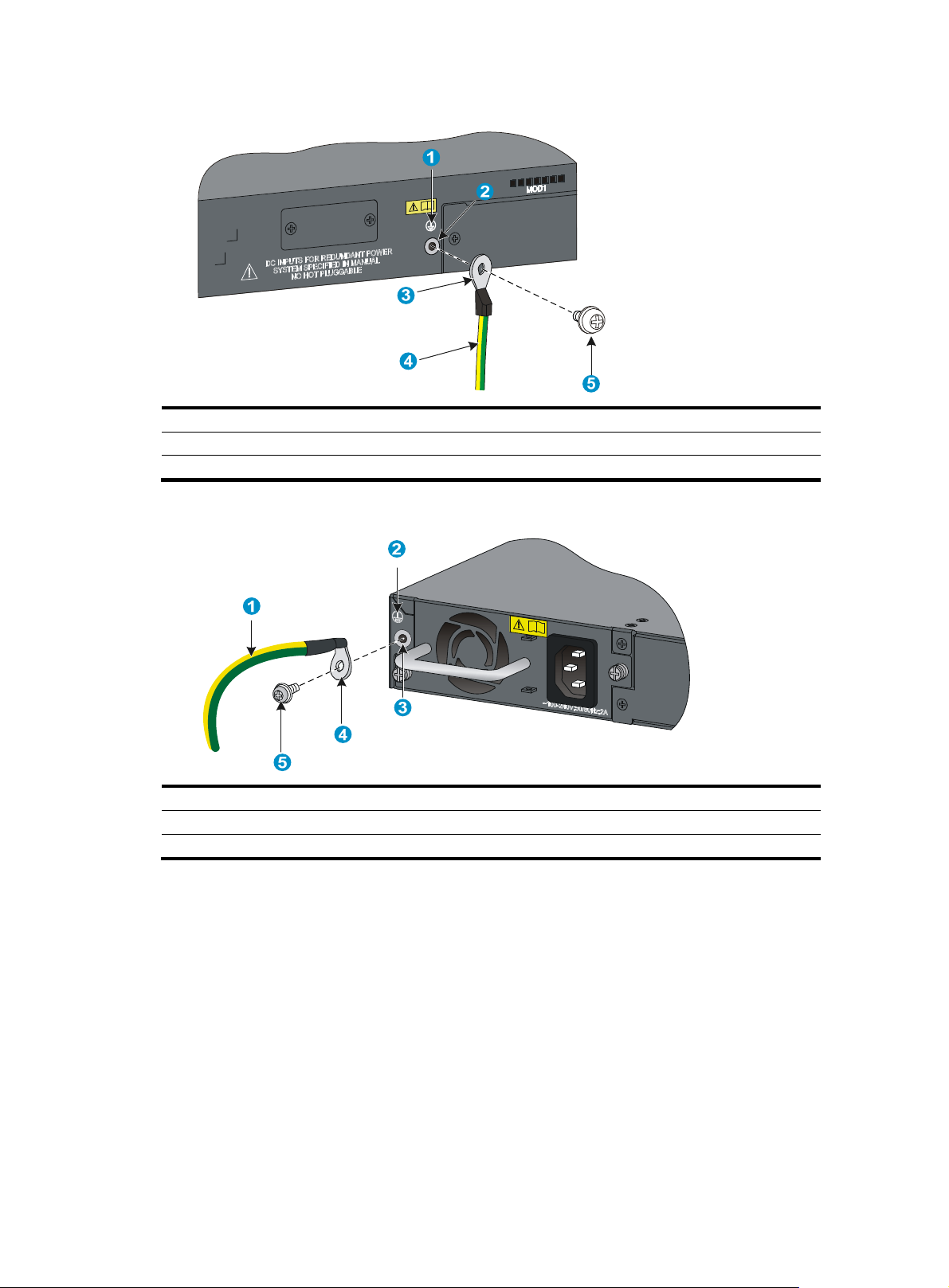
Figure 10 Connecting the grounding cable to the chassis (I)
(1) Grounding sign
(3) Ring terminal (4) Grounding cable
(5) Grounding screw
(2) Grounding hole
Figure 11 Connecting the grounding cable to the chassis (II)
(1) Grounding cable (2) Grounding sign
(3) Grounding hole (4) Ring terminal
(5) Grounding screw
4. Remove the hex nut of a grounding post on the grounding strip.
5. Cut the grounding cable as appropriate for connecting to the grounding strip.
6. Peel 5 mm (0.20 in) of insulation sheath by using a wire stripper, and insert the bare metal part
through the black insulation covering into the end of the ring terminal.
7. Secure the metal part of the cable to the ring terminal with a crimper, cover the joint with the
insulation covering, and heat the insulation covering with a blow dryer to completely cover the
metal part.
8. Attach the ring terminal or the ring to the grounding strip through the grounding post, and fasten
it with the removed hex nut, as shown in Figure 13.
14
Page 20
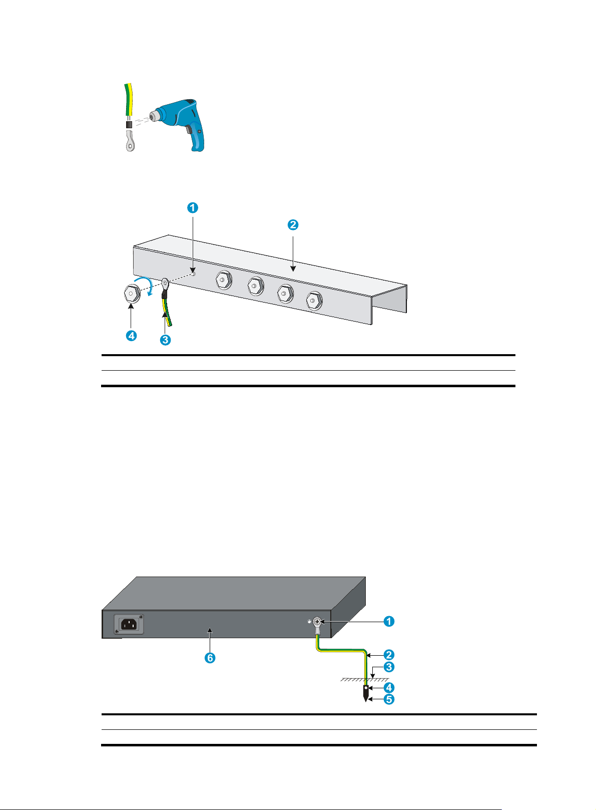
Figure 12 Making a grounding cable connector
Figure 13 Connecting the grounding cable to a grounding strip
(1) Grounding post (2) Grounding strip
(3) Grounding cable (4) Hex nut
Grounding the switch with a grounding conductor buried in the earth ground
If the installation site has no grounding strips, but earth ground is available, hammer a 0.5 m (1.64 ft) or
longer angle iron or steel tube into the earth ground to serve as a grounding conductor.
The dimensions of the angle iron must be at least 50 × 50 × 5 mm (1.97 × 1.97 × 0.20 in). The steel tube
must be zinc-coated and its wall thickness must be at least 3.5 mm (0.14 in).
Weld the yellow-green grounding cable to the angel iron or steel tube and treat the joint for corrosion
protection.
Figure 14 Grounding the switch by burying the grounding conductor into the earth ground
(1) Grounding screw (2) Grounding cable
(4) Joint (5) Grounding conductor
15
(3) Earth ground
(6) Chassis rear panel
Page 21

g
t
Grounding the switch by using the AC power cord
If the installation site has no grounding strips or earth ground, you ground an AC-powered switch through
the PE wire of the power cord, but must make sure:
• The power cord has a PE terminal.
• The ground contact in the power outlet is securely connected to the ground in the power distribution
room or on the AC transformer side.
• The power cord is securely connected to the power outlet.
NOTE:
round contact in the power outlet is not connected to the ground, report the problem and reconstruc
If the
the grounding system.
Figure 15 Grounding through the PE wire of the AC power cord
(1) Three-wire AC power cable (2) Chassis rear panel
NOTE:
To guarantee the grounding effect, use the grounding cable provided with the switch to connect to the
grounding strip in the equipment room as long as possible.
Installing/removing a power supply
This section applies only to the 5500-24G-SFP EI (2 slots) and 5500-24G-SFP EI TAA (2 slots) switches.
This section uses a PSR150-A power supply as an example to describe the installation and removal of
power supplies.
Installing a power supply
16
Page 22

g
t
v
CAUTION:
• To prevent dama
e to the power supply or the connector on the backplane of the powered device, inser
the power supply gently. If you encounter a hard resistance while inserting the power supply, pull out the
power supply and then insert it again.
• If the captive screw cannot be tightly secured, verify the installation of the power supply.
To install a power supply:
1. Wear an ESD-preventive wrist strap and make sure it makes good skin contact and is well
grounded.
2. If the power supply slot is covered by a filler panel, remove the filler panel first.
Put away the filler panel for future use.
3. Unpack the power supply and verify that the power supply model is correct.
4. Correctly orient the power supply with the power supply slot, grasp the handle of the power supply
with one hand and support its bottom with the other, and slide the power supply slowly along the
guide rails into the slot (see callout 1 in Figure 16).
ot is foolproof. If you cannot insert the power supply into the slot, re-orient the power supply
The sl
rather than use excessive force to push it in.
5. Fasten the captive screws on the power supply with a Philips screwdriver to secure the power
supply in the chassis (see callout 2 in Figure 16).
Figure 16 Installing a po
wer supply
NOTE:
If you install only one power supply, install the filler panel over the empty power supply slot for good
entilation.
Removing a power supply
1. Wear an ESD-preventive wrist strap and make sure it makes good skin contact and is well
grounded.
2. Disconnect the power cord from the power supply and the power outlet.
17
Page 23

W
p
3. Loosen the captive screws of the power supply with a Philips screwdriver until they are completely
disengaged.
4. Grasp the handle of the power supply with one hand and pull it out a little, support the bottom with
the other hand, and pull the power supply slowly along the guide rails out of the slot.
NOTE:
Put away the removed power supply in an antistatic bag for future use.
Connecting the power cord
ARNING!
Make sure the grounding cable has been correctly connected before powering on the switch.
Use Table 5 to identify the power cord connection procedures available for your switch.
Table 5 Power cord connection methods at a glance
Chassis Connection
5500-24G EI (2 slots)
5500-24G EI TAA (2 slots)
5500-48G EI (2 slots)
5500-48G EI TAA (2 slots)
5500-24G SI (2 slots)
5500-48G SI (2 slots)
5500-24G-PoE+ EI (2 slots)
5500-24G-PoE+ EI TAA (2 slots)
5500-48G-PoE+ EI (2 slot)
5500-48G-PoE+ EI TAA (2 slot)
5500-24G-PoE+ SI (2 slots)
5500-48G-PoE+ SI (2 slots)
5500-24G-SFP EI (2 slots)
5500-24G-SFP EI TAA (2 slots)
AC-input:
Connecting the AC power cord
RPS input:
Connect the switch to a +12 VDC output RPS
AC-input:
Connecting the AC power cord
RPS input:
Connecting the switch to a –52 to –55 VDC output RPS
AC-input PSR150-A/PSR150-A1 power supply:
Connecting the AC power cord
DC
-input PSR150-D/PSR150-D1 power supply:
Connecting the PSR150-D/PSR150-D1 to a –48 VDC
power source
rocedure
Connecting the AC power cord
1. Wear an ESD-preventive wrist strap and make sure it makes good skin contact and is well
grounded.
2. Connect one end of the AC power cord to the AC-input power receptacle on the switch or the
power supply (see Figure 17).
3. Conne
ct the other end of the AC power cord to the AC power outlet.
18
Page 24

Figure 17 Connecting the AC power cord
Connecting the PSR150-D/PSR150-D1 to a –48 VDC power source
CAUTION:
Identify the positive (+) and negative (-) marks on the two wires to avoid connection mistakes.
To connect the PSR150-D/PSR150-D1 to a –48 VDC power source:
1. Wear an ESD-preventive wrist strap and make sure it makes good skin contact and is well
2. Unpack the DC power cord, correctly orient the plug at one end of the cable with the power
3. Tighten the screws on the plug with a flat-blade screwdriver to secure the plug in the power
4. Conne
grounded.
receptacle on the power supply, and insert the plug into the power receptacle (see callout 1
in Figure 18).
T
he power receptacle is foolproof. If you cannot insert the plug into the receptacle, re-orient the
plug rather than use excessive force to push it in.
receptacle (see callout 2 in Figure 18).
ct the two wires at the other end of the power cord to a –48 VDC power source.
Figure 18 Connecting a –48V DC power cord
NOTE:
You can also connect the PSR150-D/PSR150-D1 to an RPS that provides –48 VDC output. The connection
procedure is the same as described in "Connecting the switch to a –52 to –55 VDC output RPS."
19
Page 25

Connect the switch to a +12 VDC output RPS
This section applies to the 5500-24G EI (2 slots), 5500-24G EI TAA (2 slots), 5500-48G EI (2 slots),
5500-48G EI TAA (2 slots), 5500-24G SI (2 slots), and 5500-48G SI (2 slots) switches.
To connect these switches to the RPS that provides +12 VDC output:
1. Wear an ESD-preventive wrist strap and make sure it makes good skin contact and is well
grounded.
2. Loosen the captive screws on the RPS receptacle protective cover and remove the protective cover,
as shown in Figure 19.
If you do not
Figure 19 Removing the RPS receptacle protective cover
3. Unpack the RPS cable shipped with the RPS, identify the plug for connecting to the switch, correctly
orient the plug with the RPS receptacle on the switch chassis, and insert the plug into the receptacle
(see callout 1 in Figure 20).
The RPS recep
rather than use excessive force to push it in.
4. Tighten the screws on the plug with a flat-blade screwdriver to secure the plug in the RPS receptacle
(see callout 2 in Figure 20).
5. Connect the other end of th
Figure 20 Connecting the RPS cable to the +12 VDC RPS power receptacle of the switch
use the +12 VDC RPS receptacle, install the protective cover.
tacle is foolproof. If you cannot insert the plug into the receptacle, re-orient the plug
e power cord to the RPS.
1
2
Connecting the switch to a –52 to –55 VDC output RPS
This section applies to the 5500-24G-PoE+ EI (2 slots), 5500-24G-PoE+ EI TAA (2 slots), 5500-48G-PoE+
EI (2 slots), 5500-48G-PoE+ EI TAA (2 slots), 5500-24G-PoE+ SI (2 slots), and 5500-48G-PoE+ SI (2 slots)
switches.
To connect these switches to the RPS that provides –52 to –55 VDC output:
20
Page 26

1. Wear an ESD-preventive wrist strap and make sure it makes good skin contact and is well
grounded.
2. Unpack the RPS cable shipped with the RPS, identify the plug for connecting to the switch, correctly
orient the plug with the RPS receptacle on the switch chassis, and insert the plug into the receptacle
(see callout 1 in Figure 21).
The RPS recep
rather than use excessive force to push it in.
3. Tighten the screws on the plug with a flat-blade screwdriver to secure the plug in the RPS receptacle
(see callout 2 in Figure 21).
4. Connect the other end of th
Figure 21 Connecting the RPS cable to the –52 to –55 VDC RPS receptacle of the switch
tacle is foolproof. If you cannot insert the plug into the receptacle, re-orient the plug
e power cord to the RPS.
Installing/removing an interface card
This section applies to all 5500 EI and 5500 SI switches. For the interface cards available for the switches,
see "Interface cards."
This section uses the LSPM2SP2P interface card as an example to describe the procedures of installing
and removing an interface card.
IMPORTANT:
To set up an HP 5500 EI or 5500 SI IRF fabric, you must install interface cards. To choose a correct slot for
an interface card, see "Planning the cabling scheme."
Installing an interface card
1. Wear an ESD-preventive wrist strap and make sure it makes good skin contact and is well
grounded.
2. Loosen the mounting screws on the filler panel over the interface card slot with a Phillips
screwdriver and remove the filler panel.
21
Page 27

g
Figure 22 Removing the filler panel over an interface card slot
3. Hold the captive screws on the front panel of the interface card, and gently push the interface card
in along the slot guide rail until the interface card is in close contact with the switch chassis (see
callout 1 in Figure 23).
4. Tighten the captive screws with a Phillips screwdriver to attach the interface card in the slot (see
callout 2 in Figure 23).
Figure 23 Installing an interface card
NOTE:
• Put away the removed filler panel for future use.
• When you tighten the captive screws, the torque must not be higher than 0.4 N-m.
Removing an interface card
CAUTION:
• Do not touch the surface-mounted components directly with your hands.
• Do not use too much force during the operation.
• If no new card is to be installed, install the filler panel to prevent dust and ensure
switch.
To remove an interface card:
ood ventilation in the
22
Page 28

1. Wear an ESD-preventive wrist strap and make sure it makes good skin contact and is well
grounded.
2. Use a Phillips screwdriver to completely loosen the captive screws at both sides of the interface
card.
3. Pull the interface card along the guide rails until it completely comes out of the switch chassis.
Installing/removing a dedicated CX4/SFP+ cable
The dedicated CX4 and SFP+ cables for the 5500 EI and 5500 SI switches are hot swappable.
Installing a dedicated CX4/SFP+ cable
CAUTION:
The cable bending radius must be at least eight times the cable diameter.
To connect a CX4 or SFP+ cable to a port on a CX4/SFP+ interface card:
1. Wear an ESD-preventive wrist strap and make sure it makes good skin contact is well grounded.
2. Correctly orient one connector of the cable with the port and insert the cable connector into the
port.
Removing a dedicated CX4/SFP+ cable
1. Wear an ESD-preventive wrist strap and make sure it makes good skin contact and is well
grounded.
2. Hold the cable connector and pull the pull latch of the connector to remove the cable from the
switch.
Verifying the installation
After you complete the installation, verify that:
• There is enough space for heat dissipation around the switch, and the rack or workbench is stable.
• The grounding cable is securely connected.
• The correct power source is used.
• The power cords are correctly connected.
• All the interface cables are cabled indoors. If any cable is routed outdoors, verify that the socket
strip with lightning protection and lightning arresters for network ports have been correctly
connected.
23
Page 29

Accessing the switch for the first time
Setting up the configuration environment
The first time you access the switch you must use a console cable to connect a console terminal, for
example, a PC, to the console port on the switch.
Figure 24 Connecting the console port to a terminal
Connecting the console cable
Console cable
A console cable is an 8-core shielded cable, with a crimped RJ-45 connector at one end for connecting
to the console port of the switch, and a DB-9 female connector at the other end for connecting to the
serial port on the console terminal.
Figure 25 Console cable
Connection procedure
To connect a terminal, for example, a PC, to the switch:
1. Plug the DB-9 female connector of the console cable to the serial port of the PC.
24
Page 30

2. Connect the RJ-45 connector to the console port of the switch.
NOTE:
• Identify the mark on the console port and make sure you are connecting to the correct port.
• The serial ports on PCs do not support hot swapping. If the switch has been powered on, connect the
console cable to the PC before connecting to the switch, and when you disconnect the cable, first
disconnect from the switch.
Setting terminal parameters
To configure and manage the switch, you must run a terminal emulator program on the console terminal.
The following are the required terminal settings:
• Bits per second—9,600
• Data bits—8
• Parity—None
• Stop bits—1
• Flow control—None
• Emulation—VT100
To set terminal parameters, for example, on a Windows XP HyperTerminal:
1. Select Start > All Programs > Accessories > Communications > HyperTerminal.
The Connection Description dialog box appears.
2. Enter the name of the new connection in the Name field and click OK.
Figure 26 Connection description
3. Select the serial port to be used from the Connect using list, and click OK.
25
Page 31

Figure 27 Setting the serial port used by the HyperTerminal connection
4. Set Bits per second to 9600, Data bits to 8, Parity to None, Stop bits to 1, and Flow control to None,
and click OK.
Figure 28 Setting the serial port parameters
5. Select File > Properties in the HyperTerminal window.
26
Page 32

Figure 29 HyperTerminal window
6. On the Settings tab, set the emulation to VT100 and click OK.
Figure 30 Setting terminal emulation in Switch Properties dialog box
27
Page 33

Powering on the switch
Before powering on the switch, verify that the following conditions are met:
• The power cord is correctly connected.
• The input power voltage meets the requirement of the switch.
• The console cable is correctly connected.
• The configuration terminal (a PC, for example) has started, and its serial port settings are consistent
with the console port settings on the switch.
Power on the switch. During the startup process, you can access Boot ROM menus to perform tasks such
as software upgrade and file management. The Boot ROM interface and menu options differ with
software versions. For more information about Boot ROM menu options, see the software-matching
release notes for the device.
After the startup completes, you can access the CLI to configure the switch.
For more information about the configuration commands and CLI, see the configuration guides and
command references for the switch.
28
Page 34

A
Setting up an IRF fabric
You can use HP Intelligent Resilient Framework (IRF) technology to connect and virtualize 5500 EI
switches or 5500 SI switches into a virtual switch called an "IRF fabric" or "IRF virtual device" for
flattened network topology, and high availability, scalability, and manageability.
NOTE:
n IRF fabric cannot have both 5500 EI and 5500 SI switches.
IRF fabric setup flowchart
Figure 31 IRF fabric setup flowchart
To set up an IRF fabric:
29
Page 35

A
t
P
Step Description
Plan the installation site and IRF fabric setup parameters:
• Planning IRF fabric size and the installation site
1. Plan IRF fabric setup
• Identifying the master switch and planning IRF member IDs
• Planning IRF topology and connections
• Identifying physical IRF ports on the member switches
• Planning the cabling scheme
2. Install IRF member
switches
3. Connect the grounding
cable, power supplies
(optional), and power
cords
4. Power on the switches
5. Install interface cards
6. Configure basic IRF
settings
7. Connect the physical IRF
ports
See "Installing the switch in a 19-inch rack" a
workbench."
See "Grounding the switch" a
If an HP 5500-24G-SFP EI (2 slots) or 5500-24G-SFP EI TAA (2 slots) switch
is used, also see "Installing/removing a power supply."
N/A
See "Installing/removing an interface card."
See "Configuring basic IRF settings."
See "Connecting the physical IRF ports."
All switches except the master switch automatically reboot, and the IRF fabric
is established.
nd "Connecting the power cord."
nd "Mounting the switch on a
Planning IRF fabric setup
Planning IRF fabric size and the installation site
Choose switch models and identify the number of required IRF member switches, depending on the user
density and upstream bandwidth requirements. The switching capacity of an IRF fabric equals the total
switching capacities of all member switches.
NOTE:
s your business grows, you can plug a switch into an IRF fabric to increase the switching capacity withou
any topology change or replacement.
Identifying the master switch and planning IRF member IDs
Determin e which swi tch you wa nt to use as the mas ter for man aging a ll memb er swi tch es in th e IRF fabric.
An IRF fabric has only one master switch. You configure and manage all member switches in the IRF
fabric at the command line interface of the master switch.
NOTE:
IRF member switches will automatically elect a master. You can affect the election result by assigning a
high member priority to the intended master switch. For more information about master election, see
5500 EI & 5500 SI Switch Series IRF Configuration Guide
30
.
H
Page 36

g
Prepare an IRF member ID assignment scheme. An IRF fabric uses member IDs to uniquely identify and
manage its members, and you must assign each IRF member switch a unique member ID.
Planning IRF topology and connections
You can create an IRF fabric in daisy chain topology, or more reliably, ring topology. In ring topology,
the failure of one IRF link does not cause the IRF fabric to split as in daisy chain topology. Rather, the IRF
fabric changes to a daisy chain topology without interrupting network services.
You connect the IRF member switches through IRF ports. An IRF port is a logical interface for the internal
connection between IRF member switches. Each IRF member switch has two IRF ports: IRF-port 1 and
IRF-port 2. To use an IRF port, you must bind physical ports to it.
When connecting two neighboring IRF member switches, you must connect the physical ports of IRF-port
1 on one switch to the physical ports of IRF-port 2 on the other switch.
You can bind several physical ports to an IRF port to create an aggregate IRF link for increased
bandwidth and availability.
NOTE:
• Figure 32 an
d Figure 33 show the topologies of an IRF fabric made up of three 5500 EI or 5500 SI
switches.
• The IRF port connections in the two fi
ures are for illustration only, and more connection methods are
available.
Figure 32 IRF fabric in daisy chain topology
Figure 33 IRF fabric in ring topology
Master
IRF
fabric
Slave
Slave
31
Page 37

A
t
Identifying physical IRF ports on the member switches
Only the 10-GE ports on the IRF-capable interface cards listed in "Interface cards" can provide IRF
connections for the 5500 EI and 5500 SI switches. To use the IRF feature, you must order the cards
separately.
IMPORTANT:
ll the switches in a ring topology and the non-edge switches in a daisy chain topology must have at leas
one two-port interface card or two one-port interface cards.
Planning the cabling scheme
When you plan the cabling scheme, follow these guidelines:
• Ports assigned to the same IRF port must be on the same interface card.
• For long-distance connections, use XFP/SFP+ transceiver modules and fibers. For short-distance
connections, use CX4/SFP+ cables or twisted-pair cables. For more information, see "Interface
rds" and "SFP/SFP+/XFP transceiver modules and SFP+/CX4 cables."
ca
• If 2-port interface cards are used and the IRF links are not aggregate:
{ You can connect the interface card in slot 1 (MOD 1) on a member switch to the MOD 1 or
MOD 2 card on its neighboring switch.
{ Connect the left port on one interface card to the right port on the other interface card, as shown
in Figure 34.
Figure 34 Use 2-port interface cards to set up singl
• If 2-port interface cards are used and IRF links are aggregate:
{
Connect the interface card MOD 1 on one switch to the interface card MOD 2 on the other
e-link IRF connection
switch.
{ A port on one interface card can connect to any port on the other interface card, as shown
in Figure 35. F
or example, you can connect the left port on one interface card to the left or right
port on the other interface card.
32
Page 38

Figure 35 Use 2-port interface cards to set up multi-link IRF connection
• If both of the neighboring switches use 1-port interface cards, the port on MOD 1 on one switch
must connect to the port on MOD 2 on the other switch (see callout 1 in Figure 36).
• If one switch uses a 1-port interface card but the other switch uses a 2-port interface card:
{ If the 1-port interface card is in the MOD 1 slot, the port on the card must connect to the right
port on the 2-port interface card (see callout 2 in Figure 36.)
{ If the 1-port interface card is in the MOD 2 slot, the port on the card must connect to the left port
on the 2-port interface card.
Figure 36 Cable connections for an IRF fabric with 1-port interface cards
Configuring basic IRF settings
After you install the IRF member switches, power on the switches, and log in to each IRF member switch
(see HP 5500 EI & 5500 SI Switch Series Fundamentals Configuration Guide) to configure their member
IDs, member priorities, and IRF port bindings.
Follow these guidelines when you configure the switches:
• Assign the master switch higher member priority than any other switch.
• Bind physical ports to IRF port 1 on one switch and to IRF port 2 on the other switch.
• Execute the irf-port-configuration active command to activate the IRF port configuration.
• Execute the display irf configuration command to verify the basic IRF settings.
33
Page 39

W
For more information about configuring basic IRF settings, see HP 5500 EI & 5500 SI Switch Series IRF
Configuration Guide.
Connecting the physical IRF ports
Connect the IRF member switches as planned.
NOTE:
ear an ESD-preventive wrist strap when you connect the physical IRF ports. For how to connect them,
see
Pluggable SFP/SFP+/XFP Transceiver Modules Installation Guide
.
Accessing the IRF fabric to verify the configuration
When you are finished configuring basic IRF settings and connecting IRF ports, follow these steps to
verify the basic functionality of the IRF fabric:
1. Log in to the IRF fabric through the console port of any member switch.
2. Create a Layer 3 interface, assign it an IP address, and make sure the IRF fabric and the remote
network management station can reach each other.
3. Use Telnet, web, or SNMP to access the IRF fabric from the network management station.
See HP 5500 EI & 5500 SI Switch Series Fundamentals Configuration Guide.
4. Verify that you can manage all member switches as if they were one node.
5. Display the running status of the IRF fabric by using the commands in the table bellow.
Task Command…
Display information about the IRF fabric display irf
Display all members’ configurations that take
effect after switch reboots
Display topology information about the IRF
fabric
display irf configuration
display irf topology
NOTE:
To avoid IP address collision and network problems, configure at least one multi-active detection (MAD)
mechanism to detect the presence of multiple identical IRF fabrics and handle collisions. For more
information about MAD detection, see
HP 5500 EI & 5500 SI Switch Series IRF Configuration Guide
.
34
Page 40

Maintenance and troubleshooting
Power supply failure
Built-in power supply failure
Except the 5500 -24G-SFP EI (2 slots) and 5500 -24G-SFP EI TAA (2 sl ot s) switches, all 5500 EI and 5500
SI switches use built-in power supplies and support three input modes: AC input, RPS DC input, and
concurrent AC and RPS DC inputs.
You can look at the system status LED and the RPS status LED on the front panel of the switch to identify
a power failure. For more information, see "LEDs."
AC input
If the system status LED is off, an AC input failure has occurred. Verify the following items:
• The AC power cord is securely connected to the switch, and the AC-input power receptacle on the
switch and the connected AC power outlet are in good condition.
• The external AC power system is correctly working.
• The operating temperature of the switch is in the normal range, and the power module has good
ventilation. Over-temperature can cause the power module to stop workin g and enter the protection
state.
RPS DC input
If the system status LED or RPS status LED is off, an RPS input failure has occurred. Verify the following
items:
• The switch is securely connected to the RPS.
• The RPS is correctly working.
• The operating temperature of the switch is in the normal range, and the power supply has good
ventilation. Over-temperature can cause the power supply to stop working and enter the protection
state).
Concurrent RPS and AC inputs
1. If the system status LED is off, the AC power supply and the RPS both have an input failure.
Verify the following items:
{ The AC power cord is securely connected to the switch, and the AC-input power receptacle on
the switch and the connected AC power outlet are in good condition.
{ The external AC power system is correctly working.
{ The switch is securely connected to the RPS.
{ The RPS is correctly working.
{ The operating temperature of the switch is in the normal range, and the power supply has good
ventilation. Over-temperature can cause the power supply to stop working and enter the
protection state.
35
Page 41

k
2. If the system status LED is on but the RPS status LED is steady yellow, an AC input failure has
occurred.
Verify the following items:
{ TThe AC power cord is securely connected to the switch, and the AC-input power receptacle on
the switch and the connected AC power outlet are in good condition.
{ The external AC power system is correctly working.
3. If the system status LED is on but the RPS status LED is off, an RPS input failure has occurred.
Verify the following items:
{ The switch is securely connected to the RPS.
{ The RPS is correctly working.
NOTE:
If the problem persists, contact the HP technical support for help.
Hot swappable power supply failure
This section applies to the 5500-24G-SFP EI (2 slots) and 5500-24G-SFP EI TAA (2 slots) switches.
You can look at the PWR1 or PWR2 LED (see Table 13)
slots) or 5500-24G-SFP EI TAA (2 slots) switch and the LEDs on the power supply to identify a power
supply failure.
If the power supply system is correctly working, the power supply LEDs are steady green. If the LEDs
behave in any other way (see Table 13)
• The power cord is correctly connected.
• The power supply meets the requirement.
• The operating temperature of the switch is in the normal range and the power supply has good
ventilation.
NOTE:
If the problem persists, contact your local sales agent or service engineer.
To replace a hot swappable power supply, see "Installing/removing a power supply."
Fan failure
You can look at the system status LED and the seven-segment LED of the switch to identify a fan failure.
If both LEDs are behaving as described in Table 6,
Table 6 LED behaviors that identify a fan failure
on the front panel of an HP 5500-24G-SFP EI (2
, verify the following items:
a fan failure occurs.
LED Mar
System status LED PWR/SYS Steady red
Seven-segment LED Unit
State
The LED flashes F for fan failure.
36
Page 42

The 5500 EI and 5500 SI switches use built-in fans. If a fan failure occurs, contact the HP technical
support for help and do not attempt to fix the problem yourself.
Configuration terminal problems
If the configuration environment setup is correct, the configuration terminal displays booting information
when the switch is powered on. If the setup is incorrect, the configuration terminal would display nothing
or garbled text.
No terminal display
If the configuration terminal displays nothing after the switch is powered on, verify the following items:
• The power supply is supplying power to the switch.
• The console cable is correctly connected.
• The console cable has no problem and the terminal settings are correct.
Garbled terminal display
If terminal display is garbled, verify that the following settings are configured for the terminal, for
example, HyperTerminal:
• Baud rate—9,600
• Data bits—8
• Parity—none
• Stop bits—1
• Flow control—none
• Emulation—VT100
37
Page 43

yp
Appendix A Chassis views and technical specifications
The HP 5500 EI & 5500 SI Switch Series includes the models in Table 7.
Table 7 Models in the HP 5500 EI & 5500 SI Switch Series
T
e Product code HP description
Alias
Non-PoE
JD377A
JG250A
JD375A
JG251A
JD374A
JG249A
JD369A
JD370A
JG241A
JG252A
HP 5500-24G EI Switch with 2 Interface
Slots
HP 5500-24G EI TAA Switch with 2
Interface Slots
HP 5500-48G EI Switch with 2 Interface
Slots
HP 5500-48G EI TAA Switch with 2
Interface Slots
HP 5500-24G-SFP EI Switch with 2
Interface Slots
HP 5500-24G-SFP EI TAA Switch with 2
Interface Slots
HP 5500-24G SI Switch with 2 Interface
Slots
HP 5500-48G SI Switch with 2 Interface
Slots
HP 5500-24G-PoE+ EI Switch with 2
Interface Slots
HP 5500-24G-PoE+ EI TAA Switch with 2
Interface Slots
5500-24G EI (2 slots)
5500-24G EI TAA(2 slots)
5500-48G EI (2 slots)
5500-48G EI TAA (2 slots)
5500-24G-SFP EI (2 slots)
5500-24G-SFP EI TAA (2
slots)
5500-24G SI (2 slots)
5500-48G SI (2 slots)
5500-24G-PoE+ EI (2 slots)
5500-24G-PoE+ EI TAA (2
slots)
JG240A
PoE
JG253A
JG238A
JG239A
HP 5500-48G-PoE+ EI Switch with 2
Interface Slots
HP 5500-48G-PoE+ EI TAA Switch with 2
Interface Slots
HP 5500-24G-PoE+ SI Switch with 2
Interface Slots
HP 5500-48G-PoE+ SI Switch with 2
Interface Slots
38
5500-48G-PoE+ EI (2 slots)
5500-48G-PoE+ EI TAA (2
slots)
5500-24G-PoE+ SI (2 slots)
5500-48G-PoE+ SI (2 slots)
Page 44

Chassis views
5500-24G EI (2 slots)/5500-24G EI TAA (2 slots)/5500-24G SI (2 slots)
Figure 37 Front panel
(1) 10/100/1000Base-T auto-sensing Ethernet port (2) 10/100/1000Base-T Ethernet port LED
(3) 1000Base-X SFP port (4) 1000Base-X SFP port LED
(5) Console port (6) Seven-segment LED (Unit)
(7) Port mode LED (Mode) (8) System status LED (PWR)
(9) RPS status LED (RPS) (10) Interface card 1 status LED (MOD1)
(11) Interface card 2 status LED (MOD2) (12) Port LED mode switching button
Figure 38 Rear panel
(1) AC power input (2) RPS receptacle (shipped with a protective cover)
(3) Grounding screw (4) Interface card slot 1 (MOD1)
(5) Interface card slot 2 (MOD2)
NOTE:
The 5500-24G EI (2 slots), 5500-24G EI TAA (2 slots), and 5500-24G SI (2 slots) switches come with the
expansion interface card slots covered by filler panels.
39
Page 45

5500-48G EI (2 slots)/5500-48G EI TAA (2 slots)/5500-48G SI (2 slots)
Figure 39 Front panel
(1) 10/100/1000Base-T auto-sensing Ethernet port (2) 10/100/1000Base-T Ethernet port LED
(3) Console port (4) Seven-segment LED (Unit)
(5) Port mode LED (Mode) (6) System status LED (PWR)
(7) RPS status LED (RPS) (8) Interface card 1 status LED (MOD1)
(9) Interface card 2 status LED (MOD2) (10) Port LED mode switching button
(11) 1000Base-X SFP port (12) 1000Base-X SFP port LED
Figure 40 Rear panel
(1) AC power input (2) RPS receptacle (shipped with a protective cover)
(3) Grounding screw (4) Interface card slot 1 (MOD1)
(5) Interface card slot 2 (MOD2)
NOTE:
The 5500-48G EI (2 slots), 5500-48G EI TAA (2 slots), and 5500-48G SI (2 slots) switches come with the
expansion interface card slots covered by filler panels.
40
Page 46

y
5500-24G-SFP EI (2 slots)/5500-24G-SFP EI TAA (2 slots)
Figure 41 Front panel
(1) SFP port (2) SFP port LED
(3) 10/100/1000Base-T auto-sensing Ethernet
port
(5) Console port (6) Port LED mode switching button
(7) Interface card 1 status LED (MOD1)
(9) System status LED (SYS) (10) Power supply 1 status LED (PWR1)
(11) Power supply 2 status LED (PWR2)
(13) Seven-segment LED (Unit)
(4) 10/100/1000Base-T Ethernet port LED
(8) Interface card 2 status LED (MOD2)
(12) Port mode LED (Mode)
Figure 42 Rear panel
(1) Grounding screw (2) Power supply slot 1
(3) Power supply slot 2 (4) Interface card slot 1 (MOD1)
(5) Interface card slot 2 (MOD2)
NOTE:
• The 5500-24G-SFP EI (2 slots) and 5500-24G-SFP EI TAA (2 slots) switches come with the expansion
interface card slots covered by filler panels.
• The 5500-24G-SFP EI (2 slots) and 5500-24G-SFP EI TAA (2 slots) switches come with one power
supply filler panel. If you use only one power supply, install the filler panel over the empty power suppl
slot to prevent dust and ensure normal ventilation of the chassis. In this figure, a PSR150-A is installed in
power supply slot 1 and a PSR150-D is installed in power supply slot 2.
41
Page 47

5500-24G-PoE+ EI (2 slots)/5500-24G-PoE+ EI TAA (2 slots)/5500-24G-PoE+ SI (2 slots)
Figure 43 Front panel
(1) 10/100/1000Base-T auto-sensing Ethernet port (2) 10/100/1000Base-T Ethernet port LED
(3) 1000Base-X SFP port (4) 1000Base-X SFP port LED
(5) Console port (6) Seven-segment LED (Unit)
(7) Port mode LED (Mode) (8) System status LED (PWR)
(9) RPS status LED (RPS) (10) Interface card 1 status LED (MOD1)
(11) Interface card 2 status LED (MOD2)
(12) Port LED mode switching button
Figure 44 Rear panel
(1) RPS receptacle (2) AC power input
(3) Grounding screw (4) Interface card slot 1 (MOD1)
(5) Interface card slot 2 (MOD2)
NOTE:
The 5500-24G-PoE+ EI (2 slots), 5500-24G-PoE+ EI TAA (2 slots), and 5500-24G-PoE+ SI (2 slots)
switches come with the expansion interface card slots covered by filler panels.
42
Page 48

5500-48G-PoE+ EI (2 slots)/5500-48G-PoE+ EI TAA (2 slots)/5500-48G-PoE+ SI (2 slots)
Figure 45 Front panel
(1) 10/100/1000Base-T auto-sensing Ethernet port (2) 10/100/1000Base-T Ethernet port LED
(3) Console port (4) Seven-segment LED (Unit)
(5) Port mode LED (Mode) (6) System status LED (PWR)
(7) RPS status LED (RPS) (8) Interface card 1 status LED (MOD1)
(9) Interface card 2 status LED (MOD2) (10) Port LED mode switching button
(11) 1000Base-X SFP port (12) 1000Base-X SFP port LED
Figure 46 Rear panel
(1) RPS receptacle (2) AC power input
(3) Grounding screw (4) Interface card slot 1 (MOD1)
(5) Interface card slot 2 (MOD2)
NOTE:
The 5500-48G-PoE+ EI (2 slots), 5500-48G-PoE+ EI TAA (2 slots), and 5500-48G-PoE+ SI (2 slots)
switches come with the expansion interface card slots covered by filler panels.
Technical specifications
Chassis dimensions and weights
Chassis Dimensions Dimensions (H × W × D) Weight
5500-24G SI (2 slots)
43.6 × 440 × 300 mm
(1.72 × 17.32 × 11.81 in)
43
< 4.5 kg (9.92 lb)
Page 49

p
Chassis Dimensions Dimensions (H × W × D) Weight
5500-24G EI (2 slots)
5500-24G EI TAA (2 slots)
5500-48G EI (2 slots)
5500-48G EI TAA (2 slots)
5500-48G SI (2 slots)
43.6 × 440 × 300 mm
(1.72 × 17.32 × 11.81 in)
< 5 kg (11.02 lb)
5500-24G-SFP EI (2 slots)
5500-24G-SFP EI TAA (2 slots)
5500-24G-PoE+ SI (2 slots)
5500-24G-PoE+ EI (2 slots)
5500-24G-PoE+ EI TAA (2 slots)
5500-48G-PoE+ SI (2 slots)
5500-48G-PoE+ EI (2 slots)
5500-48G-PoE+ EI TAA (2 slots)
43.6 × 440 × 360 mm
(1.72 × 17.32 × 14.17 in)
43.6 × 440 × 420 mm
(1.72 × 17.32 × 16.54 in)
43.6 × 440 × 420 mm
(1.72 × 17.32 × 16.54 in)
43.6 × 440 × 420 mm
(1.72 × 17.32 × 16.54 in)
Ports and interface card slots
Chassis
5500-24G EI (2 slots)
5500-24G EI TAA (2 slots)
5500-24G SI (2 slots)
5500-24G-PoE+ EI (2 slots)
5500-24G-PoE+ EI TAA (2 slots)
5500-24G-PoE+ SI (2 slots)
Console
ports
1 24 4 2
1 24, PoE+ 4 2
10/100/1000Base-T
auto-sensing Ethernet
orts
< 6 kg (13.23 lb)
< 7.0 kg (15.43 lb)
< 7.5 kg (16.53 lb)
< 8.0 kg (17.64 lb)
SFP ports
Interafce
card slots
5500-24G-SFP EI (2 slots)
5500-24G-SFP EI TAA (2 slots)
5500-48G EI (2 slots)
5500-48G EI TAA (2 slots)
5500-48G SI (2 slots)
5500-48G-PoE+ EI (2 slots)
5500-48G-PoE+ EI TAA (2 slots)
5500-48G-PoE+ SI (2 slots)
1 8 24 2
1 48 4 2
1 48, PoE+ 4 2
44
Page 50

r
p
NOTE:
• On an HP 5500-24G-SFP EI (2 slots) or 5500-24G-SFP EI TAA (2 slots) switch, the last eight SFP ports
and the eight 10/100/1000Base-T Ethernet ports are copper/fiber combo ports in pairs, as shown
in Table 10. T
automatically shuts down.
• On any other 5500 EI or 5500 SI switch, the last four 10/100/1000Base-T Ethernet ports and the fou
SFP ports are copper/fiber combo ports in pairs, as shown in Table 10. They form four combo
interfaces. When one port in a pair is activated, the other port automatically shuts down.
hey form eight combo interfaces. When one port in a pair is activated, the other port
Environmental specifications
Chassis Operating temperature
All chassis 0°C to 45°C (32°F to 113°F) 10% to 90%, noncondensing
Power specifications
Power input types
Chassis
5500-24G-SFP EI
(2 slots) and
5500-24G-SFP EI
TAA (2 slots)
Other 5500 EI and
5500 SI switches
The RPS can supply power to your switch when the AC power line fails or cannot supply sufficient power.
AC-input power
tacle
rece
N/A N/A
1 1 N/A
AC input voltage specifications
RPS receptacle Power supply slots
Relative humidity
2 (For the available power
supplies, see "Hot swappable
power suppli
es".)
Chassis Rated voltage range
All chassis
100 VAC to 240 VAC, 50 Hz or 60
Hz
45
Max voltage range
90 VAC to 264 VAC, 47 Hz to 63 Hz
Page 51

g
p
p
p
RPS DC input voltage specifications and RPS compatibility
Chassis
5500-24G EI (2 slots)
5500-24G EI TAA (2 slots)
5500-24G SI (2 slots)
5500-48G EI (2 slots)
5500-48G EI TAA (2 slots)
5500-48G SI (2 slots)
5500-24G-PoE+ EI (2 slots)
5500-24G-PoE+ EI TAA (2 slots)
5500-24G-PoE+ SI (2 slots)
5500-48G-PoE+ EI (2 slots)
5500-48G-PoE+ EI TAA (2 slots)
5500-48G-PoE+ SI (2 slots)
RPS input rated voltage
e
ran
10.8 VDC to 13.2 VDC A-RPS800 (JD183A)
–52 VDC to –55 VDC A-RPS1600 (JG136A)
Compatible RPS
Power consumption specifications for non-PoE switches
Chassis
Minimum power
consum
tion
Maximum power consumption
5500-24G EI (2 slots)
5500-24G EI TAA (2 slots)
5500-24G SI (2 slots) 36 W 103 W
5500-24G-SFP EI (2 slots)
5500-24G-SFP EI TAA (2 slots)
5500-48G EI (2 slots)
5500-48G EI TAA (2 slots)
5500-48G SI (2 slots) 55 W 145 W
36 W 110 W
PSR150-A/PSR150-A1
(JD362A): 44 W
PSR150-D/PSR150-D1
(JD366A): 30 W
63 W 155 W
115 W
Power consumption specifications for PoE switches
Maximum power
consumption (including
total PoE out
591 W at AC input
492 W at RPS DC input
Chassis
5500-24G-PoE+ EI (2
slots)
5500-24G-PoE+ EI
TAA (2 slots)
Maximum PoE
power per port
30 W 370 W 60 W
Total PoE
output
Minimum
power
consum
tion
ut)
5500-24G-PoE+ SI (2
slots)
30 W 370 W 62 W
46
585 W at AC input
491 W at RPS DC input
Page 52

p
p
Chassis
5500-48G-PoE+ EI (2
slots)
5500-48G-PoE+ EI
TAA (2 slots)
5500-48G-PoE+ SI (2
slots)
Cooling system
Maximum PoE
power per port
30 W
30 W
Total PoE
output
370 W at AC
input
740 W at RPS
DC input (370
W for ports 1 to
24, and 370 W
for ports 25 to
48)
370 W at AC
input
740 W at RPS
DC input (370
W for ports 1 to
24, and 370 W
for ports 25 to
48)
Minimum
power
consum
85 W
90 W
tion
Maximum power
consumption (including
total PoE out
661 W at AC input
930 W at RPS DC input
651 W at AC input
921 W at RPS DC input
ut)
All 5500 EI and 5500 SI switches use built-in fans for heat dissipation, and the airflow is from left to right.
Chassis Built-in fans
5500-24G EI (2 slots)
5500-24G EI TAA (2 slots)
5500-24G SI (2 slots)
5500-48G EI (2 slots)
5500-48G EI TAA (2 slots)
5500-48G SI (2 slots)
5500-24G-PoE+ EI (2 slots)
5500-24G-PoE+ EI TAA (2 slots)
5500-24G-PoE+ SI (2 slots)
5500-48G-PoE+ EI (2 slots)
5500-48G-PoE+ EI TAA (2 slots)
5500-48G-PoE+ SI (2 slots)
5500-24G-SFP EI (2 slots)
5500-24G-SFP EI TAA (2 slots)
4
6
6 (4 for the system, and 1 for each power
supply)
47
Page 53

p
s
Appendix B FRUs and compatibility matrixes
This appendix describes the FRUs available for the 5500 EI and 5500 SI switches and their compatibility.
Hot swappable power supplies
This section applies to the 5500-24G-SFP EI (2 slots) and 5500-24G-SFP EI TAA (2 slots) switches.
Power supply S
PSR150-A (JD362A)
PSR150-A1 (JD362A)
PSR150-D (JD366A)
PSR150-D1 (JD366A)
ecifications
• Rated input voltage range:
100 VAC to 240 VAC @ 50 Hz or 60 Hz
• Max input voltage range:
90 VAC to 264 VAC @ 47 Hz to 63 Hz
• Output voltage:
12 V
• Max output current:
12.5 A
• Max output power:
150 W
• Rated input voltage range:
–48 VDC to –60 VDC
• Max input voltage range:
–36 VDC to –72 VDC
• Output voltage:
12 V
• Max output current:
12.5 A
• Max output power:
150 W
NOTE:
• The 5500-24G-SFP EI (2 slots) and 5500-24G-SFP EI TAA (2 slots) switches support the mix of a
PSR150-A/PSR150-A1 (JD362A) and a PSR150-D/PSR150-D1 (JD366A) power supply.
• For more information about the power supplies, see
User Guide.
HP PSR150-A & PSR150-D Series Power Supplie
Interface cards
The interface cards in this section are available for all 5500 EI and 5500 SI switches.
48
Page 54

Card model
LSPM2GP2P JD367A
LSPM2SP2P JD368B
LSPM1XP2P JD359B
LSPM1XP1P JD361B
LSPM1CX2P JD360B
LSPM1XGT2P JG535A
Product
code
Description Support for IRF
Provides two Gbps
SFP fiber ports
Provides two 10
Gbps SFP+ fiber
ports
Provides two 10
Gbps XFP fiber ports
Provides one 10
Gbps XFP fiber port
Provides two 10
Gbps copper ports
Provides two
1/10GBase-T
Ethernet ports
No
Yes
Yes
Yes
Yes See "CX4 cables."
Yes N/A
Compatible transceiver
modules/cables
See "GE SFP transceiver
modules."
NOTE:
card does not support the
This
transceiver module coded
JD089B.
See "10-GE SFP+ transceiver
modules" and "SFP+ cables."
See "10-GE XFP transceiver
modules."
See "10-GE XFP transceiver
modules."
NOTE:
For more information about the interface cards, see the user guides for the interface cards.
SFP/SFP+/XFP transceiver modules and SFP+/CX4 cables
NOTE:
• To guarantee the functionality of the SFP/SFP+/XFP ports, use only HP transceiver modules.
• The transceiver modules available for this switch series are subject to change over time. For the most
up-to-date list of transceiver modules, consult your HP sales representative or technical support
engineer.
• For the transceiver module specifications, see
HP A-Series Switches Transceiver Modules User Guide.
For information about installing a transceiver module, see
Installation Guide
.
SFP/SFP+/XFP Transceiver Modules
49
Page 55

μm)
GE SFP transceiver modules
Product
code
JD118B
JD119B
JD061A
Module description
HP X120 1G SFP LC SX
Transceiver
HP X120 1G SFP LC LX
Transceiver
HP X125 1G SFP LC LH40
1310nm Transceiver
Central
wavelength
(nm)
850
1310
1310 9/125 N/A
Cable/fiber
diameter
(μm)
50/125
62.5/125
9/125 N/A
50/125 500, 400
62.5/125 500
Multimode
fiber modal
bandwidth
(MHz × km)
500
400
200
160
Max
transmission
distance
550 m
(1804.46 ft)
500 m
(1640.42 ft)
275 m
(902.23 ft)
220 m
(721.78 ft)
10 km (6.21
miles)
550 m
(1804.46 ft)
550 m
(1804.46 ft)
40 km (24.86
miles)
JD062A
JD063B
JD103A
JD098B
JD099B
JD089B
IMPORTANT:
HP X120 1G SFP LC LH40
1550nm Transceiver
HP X125 1G SFP LC LH70
Transceiver
HP X120 1G SFP LC
LH100 Transceiver
HP X120 1G SFP LC BX
10-U Transceiver
HP X120 1G SFP LC BX
10-D Transceiver
HP X120 1G SFP RJ45 T
Transceiver
You must use the transceiver modules coded JD098B and JD099B in pairs.
FE SFP transceiver modules
Product code Module Description
1550 9/125 N/A
1550 9/125 N/A
1550 9/125 N/A
TX: 1310nm
RX: 1490nm
TX: 1490nm
RX: 1310nm
N/A
Central wavelength
(nm)
9/125 N/A
9/125 N/A
Category-5
twisted pair
N/A
Fiber
diameter
(
40 km (24.86
miles)
70 km (43.50
miles)
100 km (62.14
miles)
10 km (6.21
miles)
10 km (6.21
miles)
100 m
(328.08 ft)
Maximum
transmission
distance
JD102B
HP X115 100M SFP LC FX
Transceiver
1310
50
50/125 2 km (1.24 miles)
62.5/125 2 km (1.24 miles)
Page 56

μm)
Product code Module Description
JD120B
JD090A
JD091A
JD100A
JD101A
IMPORTANT:
HP X110 100M SFP LC LX
Transceiver
HP X110 100M SFP LC
LH40 Transceiver
HP X110 100M SFP LC
LH80 Transceiver
HP X110 100M SFP LC BX
10-U Transceiver
HP X110 100M SFP LC BX
10-D Transceiver
(nm)
1310 9/125
1310 9/125
1550 9/125
TX: 1310 nm
RX: 1550 nm
TX: 1550
RX: 1310
You must use the transceiver modules coded JD100A and JD101A in pairs.
Central wavelength
10-GE SFP+ transceiver modules
Fiber
diameter
(
9/125
9/125
Maximum
transmission
distance
15 km (9.32
miles)
40 km (24.86
miles)
80 km (49.71
miles)
15 km (9.32
miles)
15 km (9.32
miles)
Product code
JD092B
JD093B
JD094B
JG234A
Module
description
HP X130 10G
SFP+ LC SR
Transceiver
HP X130 10G
SFP+ LC LRM
Transceiver
HP X130 10G
SFP+ LC LR
Transceiver
HP X130 10G
SFP+ LC ER
40km
Transceiver
Central
wavelength
(nm)
850
1310
1310 9/125 N/A
1550 9/125 N/A
Fiber
diameter
(μm)
50/125
62.5/125
50/125
62.5/125 200, 160
Multimode fiber
modal bandwidth
(MHz × km)
2000
500 82 m (269.03 ft)
400 66 m (216.54 ft)
200 33 m (108.27 ft)
160 26 m (85.3 ft.)
1500, 500
400
Max
transmission
distance
300 m (984.25
ft)
220 m (721.78
ft)
100 m (328.08
ft)
220 m (721.78
ft)
10 km (6.21
miles)
40 km (24.86
miles)
NOTE:
For the SFP+ cables available for connecting the SFP+ ports, see "SFP+ cables."
51
Page 57

×
SFP+ cables
Product code Cable description
JD095C HP X240 10G SFP+ SFP+ 0.65m DA Cable 0.65 m (2.13 ft)
JD096C HP X240 10G SFP+ SFP+ 1.2m DA Cable 1.2 m (3.94 ft)
JD097C HP X240 10G SFP+ SFP+ 3m DA Cable 3 m (9.84 ft)
JG081C HP X240 10G SFP+ SFP+ 5m DA Cable 5 m (16.40 ft)
Figure 47 SFP+ cable
(1) Pull latch (2) Connector
10-GE XFP transceiver modules
Cable length
Product code
JD117B
JD108B
JD121A
JD107A
Module
description
HP X130 10G
XFP LC SR
Transceiver
HP X130 10G
XFP LC LR
1310nm
Transceiver
HP X135 10G
XFP LC ER
Transceiver
HP X130 10G
XFP LC ZR
1550nm
Transceiver
Central
wavelength
(nm)
850
1310 9/125 N/A 10 km (6.21 miles)
1550 9/125 N/A 40 km (24.86 miles)
1550 9/125 N/A 80 km (49.71 miles)
Fiber
diameter
(μm)
50/125
62.5/125
Multimode
fiber modal
bandwidth
(MHz
2000 300 m (984.25 ft)
500 82 m(269.03 ft)
400 66 m(216.54 ft)
220 33 m (108.27 ft)
160 26 m (85.3 ft)
km)
Max transmission
distance
52
Page 58

CX4 cables
Product code Cable description Connector type Cable length
JD363B
JD364B
JD365A HP X230 CX4 to CX4 3m Cable 4X Infiniband 3 m (118.11 in)
HP X230 Local Connect 50cm
CX4 Cable
HP X230 Local Connect 100cm
CX4 Cable
4X Infiniband 0.5 m (19.69 in)
4X Infiniband 1 m (39.37 in)
Figure 48 CX4 cable
(1) Pull latch (2) Connector
53
Page 59

p
p
Appendix C Ports and LEDs
Ports
Console port
Every 5500 EI or 5500 SI switch has one console port on the front panel.
Table 8 Console port specifications
Item S
Connector type
Compliant standard
Transmission baud rate 9600 bps (default) to 115200 bps
Service
ecification
RJ-45
EIA/TIA-232
• Provides connection to an ASCII terminal.
• Provides connection to the serial port of a local or remote (through a
pair of modems) PC running terminal emulation program.
10/100/1000Base-T Ethernet port
Table 9 10/100/1000Base-T Ethernet port specifications
Item S
Connector type
Interface standard
Max transmission distance
ecification
RJ-45
• 10 Mbps, half/full duplex
• 100 Mbps, half/full duplex
• 1000 Mbps, full duplex
• MDI/MDI-X, auto-sensing
100 m (328.08 ft)
Transmission medium
Standards
Category-5 (or above) twisted pair cable
IEEE 802.3i, 802.3u, 802.3ab
SFP port
All 5500 EI and 5500 SI switches have SFP ports.
• For the SFP transceiver modules available for the 5500 EI switches, see "GE SFP transceiver
modules" and "FE SFP transceiver modules."
or the SFP transceiver modules available for the 5500 SI switches, see "GE SFP transceiver
• F
modules."
54
Page 60

p
y
Combo interface
• On the 5500-24G-SFP EI (2 slots) and 5500-24G-SFP EI TAA (2 slots) switch, the last eight SFP ports
and the eight 10/100/1000Base-T Ethernet ports are copper/fiber combo ports in pairs, as shown
in Table 10. T
• On all the other 5500 EI and 5500 SI switches, the last four 10/100/1000Base-T Ethernet ports
and the four SFP ports are copper/fiber combo ports in pairs, as shown in Table 10.
combo interfaces
When one port in a pair is activated, the other port automatically shuts down. For more information
about combo interfaces, see HP 5500 EI & 5500 SI Switch Series Configuration Guides.
Table 10 Copper/fiber combo ports in pairs
hey form eight combo interfaces.
They form four
Chassis SFP
5500-24G EI (2 slots)
5500-24G EI TAA (2 slots)
5500-24G-PoE+ EI (2 slots)
5500-24G-PoE+ EI TAA (2 slots)
5500-24G SI (2 slots)
5500-24G-PoE+ SI (2 slots)
5500-48G EI (2 slots)
5500-48G EI TAA (2 slots)
5500-48G-PoE+ EI (2 slots)
5500-48G-PoE+ EI TAA (2 slots)
5500-48G SI (2 slots)
5500-48G-PoE+ SI (2 slots)
5500-24G-SFP EI (2 slots)
5500-24G-SFP EI TAA (2 slots)
GigabitEthernet 1/0/25 GigabitEthernet 1/0/22
GigabitEthernet 1/0/26 GigabitEthernet 1/0/24
GigabitEthernet 1/0/27 GigabitEthernet 1/0/21
GigabitEthernet 1/0/28 GigabitEthernet 1/0/23
GigabitEthernet 1/0/49 GigabitEthernet 1/0/46
GigabitEthernet 1/0/50 GigabitEthernet 1/0/48
GigabitEthernet 1/0/51 GigabitEthernet 1/0/45
GigabitEthernet 1/0/52 GigabitEthernet 1/0/47
GigabitEthernet 1/0/17 GigabitEthernet 1/0/25
GigabitEthernet 1/0/18 GigabitEthernet 1/0/26
GigabitEthernet 1/0/19 GigabitEthernet 1/0/27
GigabitEthernet 1/0/20 GigabitEthernet 1/0/28
GigabitEthernet 1/0/21 GigabitEthernet 1/0/29
ort 10/100/1000Base-T Ethernet port
GigabitEthernet 1/0/22 GigabitEthernet 1/0/30
GigabitEthernet 1/0/23 GigabitEthernet 1/0/31
GigabitEthernet 1/0/24 GigabitEthernet 1/0/32
LEDs
Table 11 LEDs at a glance
LED Availabilit
System status LED Entire series
Power supply status LEDs
55
5500-24G-SFP EI (2 slots)
5500-24G-SFP EI TAA (2 slots)
Page 61

y
p
p
LED Availabilit
RPS status LED
Port mode LED Entire series
Seven-segment LED Entire series
10/100/1000Base-T Ethernet port LED Entire series
SFP port status LED Entire series
Interface card status LED Entire series
System status LED
The system status LED shows the operating status of the switch.
Table 12 System status LED description
LED mark Status Descri
SYS/PWR
Entire series (except the 5500-24G-SFP EI (2 slots)
and 5500-24G-SFP EI TAA (2 slots) )
tion
Steady green The switch is operating correctly.
Flashing green (1 Hz) The switch is performing power-on self test (POST).
Steady red POST has failed.
Flashing yellow (1 Hz) Some ports have failed to pass POST.
Off The switch is powered off.
Power supply status LEDs
Only the 5500-24G-SFP EI (2 slots) and 5500-24G-SFP EI TAA (2 slots) switches have power supply status
LEDs to show the operating status of the power supplies in the power supply slots.
Table 13 Hot swappable power supply status LED description
LED Status Descri
Steady green
PWR1
PWR2
Steady yellow
Off No power supply is installed in the power supply slot.
RPS status LED
The RPS status LED shows the operating status of the RPS DC input.
tion
A power supply is installed in the power supply slot,
and the power output is normal.
A power supply is installed in the power supply slot,
but the power supply is experiencing an output error
or is not powered on.
The 5500-24G-SFP EI (2 slots) and 5500-24G-SFP EI TAA (2 slots) switches do not have an RPS status
LED.
56
Page 62

p
p
p
Table 14 RPS status LED description for the non-PoE switches
LED mark Status Descri
RPS
Table 15 RPS status LED description for the PoE switches
LED mark Status Descri
RPS
Port mode LED
The port mode LED indicates the type of information that the network port LEDs are showing. You can use
the port LED mode switching button to change the type of displayed port information.
tion
Steady green
Steady yellow
Off No RPS is connected.
Both the RPS DC input and the AC input are normal, or an RPS is
connected and the AC input is normal.
The RPS DC input is normal, but the AC input is disconnected or
has failed.
tion
Steady green Both the RPS DC input and the AC input are normal.
Steady yellow
Off The RPS power input is abnormal or no RPS is connected.
The RPS power input is normal, but the AC input is disconnected or
has failed.
Table 16 Port mode LED description
LED mark Status Descri
Steady green The network port LEDs are showing port rates.
Flashing green (1 Hz)
Mode
(available only for the PoE+
switch models)
Steady yellow The network port LEDs are showing duplex modes.
Seven-segment LED
The seven-segment LED, together with the system status LED, shows detailed system operating information
(see Table 17).
The seven-segment LED can also show the total PoE output power as a percentage of the maximum PoE
output power that a PoE switch can supply (see Table 18)
(2 slots), 5500-24G-PoE+ EI TAA (2 slots), 5500-24G-PoE+ SI (2 slots), 5500-48G-PoE+ EI (2 slots),
5500-48G-PoE+ EI TAA (2 slots), and 5500-48G-PoE+ SI (2 slots).
Table 17 Seven-segment LED description (I)
System status LED
(PWR/SYS) status
Seven-segment LED (Unit) status Description
tion
The network port LEDs are showing the status of PoE
power supply on the ports.
. The PoE switches include 5500-24G-PoE+ EI
The LED displays numbers one by one.
Flashing green
57
POST is running, and the LED displays the
ongoing test item ID.
Page 63

System status LED
(PWR/SYS) status
Flashing red
Flashing green
Steady red
Steady red
Steady green
Seven-segment LED (Unit) status Description
The LED displays flashing numbers.
A bar rotates clockwise around the LED.
The LED displays a flashing F character.
The LED displays a flashing t character.
The LED displays a capital C character.
The LED displays an S character.
The LED displays a lowercase c character.
POST has failed, and the LED flashes the
ID of the failed test item.
Software is loading.
The switch is experiencing a fan failure.
The switch is in an over-temperature
condition.
The switch is the command switch in a
cluster.
The switch is a member switch in a cluster.
The switch is a candidate switch for a
cluster.
The LED displays a number.
Table 18 Seven-segment LED description (II)
Port mode LED
(Mode) status
Flashing green
(1 Hz) (PoE
mode)
System status LED
(PWR) status
Steady green
Seven-segment LED (Unit)
status
The LED displays different signs.
81 - 100%
61 - 80%
41 - 60%
21 - 40%
0 - 20%
10/100/1000Base-T Ethernet port LED
Each 10/100/1000Base-T auto-sensing Ethernet port has a status LED to show port operating status and
activities. The port mode LED indicates the type of information (for example, port rate or duplex mode)
that the port LEDs are showing. You can use the port LED mode switching button to change the type of
displayed port information.
The member ID of the switch in an IRF
fabric.
Description
For example, the
indicates that the switch is
outputting 0 to 20% of the
maximum PoE output power.
sign
58
Page 64

Table 19 10/100/1000Base-T auto-sensing Ethernet port LEDs description
Port mode LED (Mode)
status
Steady green (rate mode)
Flashing green (1 Hz) (PoE
mode, available only for
PoE switches)
Port LED status Description
The port is operating at 1000 Mbps. The port
Steady green
Steady yellow
Flashing yellow (3 Hz) POST has failed on the port.
Off No link is present on the port.
Steady green PoE power supply is normal.
Flashing green (1 Hz)
Steady yellow
Flashing yellow (3 Hz) POST has failed on the port.
Off The port is not supplying PoE power.
status LED fast flashes when the port is sending or
receiving data.
The port is operating at 10/100 Mbps. The port
status LED fast flashes when the port is sending or
receiving data.
The device attached to the port requires power
higher than the maximum or currently available
PoE output power on the port.
The port is experiencing a PoE failure.
The port is not supplying power, because the
device attached to the port is not a powered
device.
Steady yellow (duplex
mode)
SFP port status LED
Each SFP port has a status LED to show port operating status and activities. The port mode LED indicates
the type of information (for example, port rate or duplex mode) that the port LEDs are showing. You can
use the port LED mode switching button to change the type of displayed port information.
Table 20 SFP port LEDs description
Port mode LED (Mode)
status
Steady green (rate mode) or
flashing green (1 Hz, PoE
mode)
The port is operating in full duplex mode. The port
Steady green
Steady yellow
Flashing yellow (3 Hz) POST has failed on the port.
Off No link is present on the port.
status LED fast flashes when the port is sending or
receiving data.
The port is operating in half duplex mode. The port
status LED fast flashes when the port is sending or
receiving data.
Port LED status Description
The port is operating at 1000 Mbps. The port
Steady green
Steady yellow (available
only on the 5500 EI
switches)
status LED fast flashes when the port is sending or
receiving data.
The port is operating at 100 Mbps. The port status
LED fast flashes when the port is sending or
receiving data.
59
Page 65

Port mode LED (Mode)
status
Steady yellow (duplex
mode)
Port LED status Description
Flashing yellow (3 Hz) POST has failed on the port.
Off No link is present on the port.
Steady green
Flashing yellow (3 Hz) POST has failed on the port.
Off No link is present on the port.
Interface card status LED
Table 21 Interface card status LEDs description
LED mark Status
Green
MOD1
MOD2
Flashing yellow
The port is operating in full duplex mode. The port
status LED fast flashes when the port is sending or
receiving data.
Description
The interface card is in position and operating
correctly.
The switch does not support the interface card
model, or the interface card has failed.
Off The expansion interface card slot is empty.
60
Page 66

Support and other resources
Contacting HP
For worldwide technical support information, see the HP support website:
http://www.hp.com/support
Before contacting HP, collect the following information:
• Product model names and numbers
• Technical support registration number (if applicable)
• Product serial numbers
• Error messages
• Operating system type and revision level
• Detailed questions
Subscription service
HP recommends that you register your product at the Subscriber's Choice for Business website:
http://www.hp.com/go/wwalerts
After registering, you will receive email notification of product enhancements, new driver versions,
firmware updates, and other product resources.
Related information
Documents
To find related documents, browse to the Manuals page of the HP Business Support Center website:
http://www.hp.com/support/manuals
• For related documentation, navigate to the Networking section, and select a networking category.
• For a complete list of acronyms and their definitions, see HP A-Series Acronyms.
Websites
• HP.com http://www.hp.com
• HP Networking http://www.hp.com/go/networking
61
 Loading...