

Page 1
hp color LaserJet 5500
5500n 5500dn 5500dtn 5500hdn
service
Page 2

Page 3

hp color LaserJet 550 0 series printe r
service manual
Page 4

© Copyright Hewlett-Packard
Company, 2002
All Rights Reserved.
Reproduction, adaptation, or
translation without prior written
permission is prohibited, except
as allowed under the copyright
laws.
Part number: C9656-90930
First Edition, July 2002
Warranty
The information contained in this
document is subject to change
without notice.
Hewlett-Packard makes no
warranty of any kind with respect
to this information. HEWLETTPACKARD SPECIFICALL Y
DISCLAIMS THE IM PL IED
WARRANTY OF
MERCHANTABILITY AND
FITNESS FOR A PARTICULAR
PURPOSE.
Hewlett-Packard shall not be
liable for any direct, indirect,
incidental, consequential, or other
damage alleged in connection
with the furnishing or use of this
information.
Trademark Credits
Adobe and Adobe Photoshop are
trademarks of Adobe Systems
Incorporated.
CorelDRAW™ is a trademark of
Corel Corporation or Corel
Corporation Limited.
NERGY STAR is a U.S. registered
E
service mark of the United States
Environmental Protection Agency.
®
Microsoft
trademark of Microsoft
Corporation.
Netscape is a U.S. trademark of
Netscape Communications
Corporation.
PANTONE
check-standard trademark for
color.
PostScript is a trademark of
Adobe Systems, Incorporated,
which may be registered in
certain jurisdictions.
TrueType is a U.S. trademark of
Apple Computer, Inc.
UNIX is a registered trademark of
the Open Group.
Windows, MS Windows, and
Windows NT are U.S. registered
trademarks of Microsoft
Corporation.
is a U.S. registered
®
Pantone, Inc.’s
Hewlett-Pack ard Company
11311 Chinden Boulevard
Boise, Idaho 83714 U.S.A.
Page 5

Conventions
This manual uses the following conventions:
● COLOR is used to emphasize items that are important to the material under discussion.
● Bold is used for menu items to click and for emphasis, particularly in situations where italic type
would be confusing.
● Italic type is used to indicate related documents or emphasis.
● DISPLAY type indicates text as seen on the printer control panel display.
● Commands you use on a computer keyboard or on the printer control panel are shown in
K
EYCAP. Two examples are PAUSE/RESUME and CANCEL JOB.
● COURIER type indicates text that you type on a computer keyboard exactly as shown.
Note Notes contain important information set off from the text.
CAUTION Caution messages alert you to the possibility of damage to equipment or loss of data.
WARNING! Warning messages alert you to the possibility of personal injury.
ENWW iii
Page 6

iv ENWW
Page 7

Contents
1 Printer description
Printer features . . . . . . . . . . . . . . . . . . . . . . . . . . . . . . . . . . . . . . . . . . . . . . . . . . . . . . . . . . . . . . . . . . 12
Identification . . . . . . . . . . . . . . . . . . . . . . . . . . . . . . . . . . . . . . . . . . . . . . . . . . . . . . . . . . . . . . . . . . . . 15
Model and serial numbers . . . . . . . . . . . . . . . . . . . . . . . . . . . . . . . . . . . . . . . . . . . . . . . . . . . . . . 15
Power and regulatory information. . . . . . . . . . . . . . . . . . . . . . . . . . . . . . . . . . . . . . . . . . . . . . . . . 16
Site requirements . . . . . . . . . . . . . . . . . . . . . . . . . . . . . . . . . . . . . . . . . . . . . . . . . . . . . . . . . . . . . . . . 17
Space requirements . . . . . . . . . . . . . . . . . . . . . . . . . . . . . . . . . . . . . . . . . . . . . . . . . . . . . . . . . . . 18
Electrical specifications. . . . . . . . . . . . . . . . . . . . . . . . . . . . . . . . . . . . . . . . . . . . . . . . . . . . . . . . . 19
Environmental specifications . . . . . . . . . . . . . . . . . . . . . . . . . . . . . . . . . . . . . . . . . . . . . . . . . . . . 19
Supply storage requirements . . . . . . . . . . . . . . . . . . . . . . . . . . . . . . . . . . . . . . . . . . . . . . . . . . . . 20
Printer specifications . . . . . . . . . . . . . . . . . . . . . . . . . . . . . . . . . . . . . . . . . . . . . . . . . . . . . . . . . . . . . . 20
Printer assemblies. . . . . . . . . . . . . . . . . . . . . . . . . . . . . . . . . . . . . . . . . . . . . . . . . . . . . . . . . . . . . . . . 21
Media requirements. . . . . . . . . . . . . . . . . . . . . . . . . . . . . . . . . . . . . . . . . . . . . . . . . . . . . . . . . . . . . . . 23
Selecting print media . . . . . . . . . . . . . . . . . . . . . . . . . . . . . . . . . . . . . . . . . . . . . . . . . . . . . . . . . . 23
Media specifications . . . . . . . . . . . . . . . . . . . . . . . . . . . . . . . . . . . . . . . . . . . . . . . . . . . . . . . . . . . 23
Paper orientation . . . . . . . . . . . . . . . . . . . . . . . . . . . . . . . . . . . . . . . . . . . . . . . . . . . . . . . . . . . . . 23
Supported media weights and sizes . . . . . . . . . . . . . . . . . . . . . . . . . . . . . . . . . . . . . . . . . . . . . . 24
Media specifications for 2-sided (duplex) printing. . . . . . . . . . . . . . . . . . . . . . . . . . . . . . . . . . . . . 26
Media to avoid . . . . . . . . . . . . . . . . . . . . . . . . . . . . . . . . . . . . . . . . . . . . . . . . . . . . . . . . . . . . . . . 27
Media that may cause damage to the printer . . . . . . . . . . . . . . . . . . . . . . . . . . . . . . . . . . . . . . . . 27
Printing on special media . . . . . . . . . . . . . . . . . . . . . . . . . . . . . . . . . . . . . . . . . . . . . . . . . . . . . . . 27
Weight equivalence table . . . . . . . . . . . . . . . . . . . . . . . . . . . . . . . . . . . . . . . . . . . . . . . . . . . . . . . 31
Environmental product stewardship program . . . . . . . . . . . . . . . . . . . . . . . . . . . . . . . . . . . . . . . . . . . 32
Protecting the environment. . . . . . . . . . . . . . . . . . . . . . . . . . . . . . . . . . . . . . . . . . . . . . . . . . . . . . 32
Regulatory statements . . . . . . . . . . . . . . . . . . . . . . . . . . . . . . . . . . . . . . . . . . . . . . . . . . . . . . . . . . . . 34
FCC Regulations . . . . . . . . . . . . . . . . . . . . . . . . . . . . . . . . . . . . . . . . . . . . . . . . . . . . . . . . . . . . . 34
Safety information . . . . . . . . . . . . . . . . . . . . . . . . . . . . . . . . . . . . . . . . . . . . . . . . . . . . . . . . . . . . . . . . 35
Laser safety statement . . . . . . . . . . . . . . . . . . . . . . . . . . . . . . . . . . . . . . . . . . . . . . . . . . . . . . . . . 35
Material Safety Data Sheet . . . . . . . . . . . . . . . . . . . . . . . . . . . . . . . . . . . . . . . . . . . . . . . . . . . . . 35
Toner safety . . . . . . . . . . . . . . . . . . . . . . . . . . . . . . . . . . . . . . . . . . . . . . . . . . . . . . . . . . . . . . . . . 35
Canadian DOC regulations. . . . . . . . . . . . . . . . . . . . . . . . . . . . . . . . . . . . . . . . . . . . . . . . . . . . . . 35
EMI statement (Korea) . . . . . . . . . . . . . . . . . . . . . . . . . . . . . . . . . . . . . . . . . . . . . . . . . . . . . . . . . 35
VCCI statement (Japan) . . . . . . . . . . . . . . . . . . . . . . . . . . . . . . . . . . . . . . . . . . . . . . . . . . . . . . . . 36
Laser statement for Finland . . . . . . . . . . . . . . . . . . . . . . . . . . . . . . . . . . . . . . . . . . . . . . . . . . . . . 37
Declaration of Conformity. . . . . . . . . . . . . . . . . . . . . . . . . . . . . . . . . . . . . . . . . . . . . . . . . . . . . . . 38
Contents v
Page 8

2 Service approach
Service approach . . . . . . . . . . . . . . . . . . . . . . . . . . . . . . . . . . . . . . . . . . . . . . . . . . . . . . . . . . . . . . . . 40
Parts and supplies . . . . . . . . . . . . . . . . . . . . . . . . . . . . . . . . . . . . . . . . . . . . . . . . . . . . . . . . . . . . . . . 41
Ordering parts . . . . . . . . . . . . . . . . . . . . . . . . . . . . . . . . . . . . . . . . . . . . . . . . . . . . . . . . . . . . . . . 41
Ordering supplies . . . . . . . . . . . . . . . . . . . . . . . . . . . . . . . . . . . . . . . . . . . . . . . . . . . . . . . . . . . . 41
Exchange program. . . . . . . . . . . . . . . . . . . . . . . . . . . . . . . . . . . . . . . . . . . . . . . . . . . . . . . . . . . . 42
Supplies . . . . . . . . . . . . . . . . . . . . . . . . . . . . . . . . . . . . . . . . . . . . . . . . . . . . . . . . . . . . . . . . . . . . 42
World Wide Web . . . . . . . . . . . . . . . . . . . . . . . . . . . . . . . . . . . . . . . . . . . . . . . . . . . . . . . . . . . . . 42
HP service parts information compact disc . . . . . . . . . . . . . . . . . . . . . . . . . . . . . . . . . . . . . . . . . 42
HP support assistant compact disc . . . . . . . . . . . . . . . . . . . . . . . . . . . . . . . . . . . . . . . . . . . . . . . 42
Customer care reseller sales and service support center . . . . . . . . . . . . . . . . . . . . . . . . . . . . . . 42
Ordering related documentation and software . . . . . . . . . . . . . . . . . . . . . . . . . . . . . . . . . . . . . . 43
Warranty statement . . . . . . . . . . . . . . . . . . . . . . . . . . . . . . . . . . . . . . . . . . . . . . . . . . . . . . . . . . . . . . 44
Hewlett-Packard warranty statement. . . . . . . . . . . . . . . . . . . . . . . . . . . . . . . . . . . . . . . . . . . . . . 44
Limited warranty for print cartridge life . . . . . . . . . . . . . . . . . . . . . . . . . . . . . . . . . . . . . . . . . . . . . . . . 45
Transfer unit and fuser warranty. . . . . . . . . . . . . . . . . . . . . . . . . . . . . . . . . . . . . . . . . . . . . . . . . . . . . 45
HP maintenance agreements. . . . . . . . . . . . . . . . . . . . . . . . . . . . . . . . . . . . . . . . . . . . . . . . . . . . . . . 46
On-site service agreements. . . . . . . . . . . . . . . . . . . . . . . . . . . . . . . . . . . . . . . . . . . . . . . . . . . . . 46
3 Installation and configuration
Unpack the printer . . . . . . . . . . . . . . . . . . . . . . . . . . . . . . . . . . . . . . . . . . . . . . . . . . . . . . . . . . . . . . . 48
Unpacking the printer. . . . . . . . . . . . . . . . . . . . . . . . . . . . . . . . . . . . . . . . . . . . . . . . . . . . . . . . . . 49
Installation . . . . . . . . . . . . . . . . . . . . . . . . . . . . . . . . . . . . . . . . . . . . . . . . . . . . . . . . . . . . . . . . . . . . . 56
Installing the paper trays . . . . . . . . . . . . . . . . . . . . . . . . . . . . . . . . . . . . . . . . . . . . . . . . . . . . . . . 56
Connecting power . . . . . . . . . . . . . . . . . . . . . . . . . . . . . . . . . . . . . . . . . . . . . . . . . . . . . . . . . . . . 57
Installing the print cartridges . . . . . . . . . . . . . . . . . . . . . . . . . . . . . . . . . . . . . . . . . . . . . . . . . . . . 58
Installing a new overlay (optional) . . . . . . . . . . . . . . . . . . . . . . . . . . . . . . . . . . . . . . . . . . . . . . . . 61
Testing the printer operation . . . . . . . . . . . . . . . . . . . . . . . . . . . . . . . . . . . . . . . . . . . . . . . . . . . . 61
Using PowerSave . . . . . . . . . . . . . . . . . . . . . . . . . . . . . . . . . . . . . . . . . . . . . . . . . . . . . . . . . . . . 62
Connecting to a computer . . . . . . . . . . . . . . . . . . . . . . . . . . . . . . . . . . . . . . . . . . . . . . . . . . . . . . . . . 63
Parallel connections. . . . . . . . . . . . . . . . . . . . . . . . . . . . . . . . . . . . . . . . . . . . . . . . . . . . . . . . . . . 63
Network connections . . . . . . . . . . . . . . . . . . . . . . . . . . . . . . . . . . . . . . . . . . . . . . . . . . . . . . . . . . 64
Enhanced I/O (EIO) configuration . . . . . . . . . . . . . . . . . . . . . . . . . . . . . . . . . . . . . . . . . . . . . . . . . . . 66
HP Jetdirect print servers. . . . . . . . . . . . . . . . . . . . . . . . . . . . . . . . . . . . . . . . . . . . . . . . . . . . . . . 66
Available enhanced I/O interfaces . . . . . . . . . . . . . . . . . . . . . . . . . . . . . . . . . . . . . . . . . . . . . . . . 66
NetWare networks . . . . . . . . . . . . . . . . . . . . . . . . . . . . . . . . . . . . . . . . . . . . . . . . . . . . . . . . . . . . 66
Windows and Windows NT networks. . . . . . . . . . . . . . . . . . . . . . . . . . . . . . . . . . . . . . . . . . . . . . 67
AppleTalk networks . . . . . . . . . . . . . . . . . . . . . . . . . . . . . . . . . . . . . . . . . . . . . . . . . . . . . . . . . . . 67
UNIX/Linux networks . . . . . . . . . . . . . . . . . . . . . . . . . . . . . . . . . . . . . . . . . . . . . . . . . . . . . . . . . . 67
Printer drivers . . . . . . . . . . . . . . . . . . . . . . . . . . . . . . . . . . . . . . . . . . . . . . . . . . . . . . . . . . . . . . . . . . . 68
Available drivers. . . . . . . . . . . . . . . . . . . . . . . . . . . . . . . . . . . . . . . . . . . . . . . . . . . . . . . . . . . . . . 68
Additional drivers . . . . . . . . . . . . . . . . . . . . . . . . . . . . . . . . . . . . . . . . . . . . . . . . . . . . . . . . . . . . . 69
Network configuration. . . . . . . . . . . . . . . . . . . . . . . . . . . . . . . . . . . . . . . . . . . . . . . . . . . . . . . . . . . . . 70
Configuring the printer for the network. . . . . . . . . . . . . . . . . . . . . . . . . . . . . . . . . . . . . . . . . . . . . 70
Configuring Novell NetWare frame type parameters . . . . . . . . . . . . . . . . . . . . . . . . . . . . . . . . . . 70
Setting network security on the printer. . . . . . . . . . . . . . . . . . . . . . . . . . . . . . . . . . . . . . . . . . . . . . . . 71
Locking the control panel . . . . . . . . . . . . . . . . . . . . . . . . . . . . . . . . . . . . . . . . . . . . . . . . . . . . . . . 71
Using an ASCII PJL escape sequence to set network security . . . . . . . . . . . . . . . . . . . . . . . . . 72
vi ENWW
Page 9

4 Printer maintenance
Cleaning the printer and accessories . . . . . . . . . . . . . . . . . . . . . . . . . . . . . . . . . . . . . . . . . . . . . . . . . 74
Cleaning spilled toner. . . . . . . . . . . . . . . . . . . . . . . . . . . . . . . . . . . . . . . . . . . . . . . . . . . . . . . . . . 74
Periodic cleaning. . . . . . . . . . . . . . . . . . . . . . . . . . . . . . . . . . . . . . . . . . . . . . . . . . . . . . . . . . . . . . . . . 75
Cleaning the static discharge comb . . . . . . . . . . . . . . . . . . . . . . . . . . . . . . . . . . . . . . . . . . . . . . . 75
Cleaning the OHT sensor . . . . . . . . . . . . . . . . . . . . . . . . . . . . . . . . . . . . . . . . . . . . . . . . . . . . . . . 76
Approximate replacement intervals for supply items. . . . . . . . . . . . . . . . . . . . . . . . . . . . . . . . . . . . . . 78
ETB life under different circumstances . . . . . . . . . . . . . . . . . . . . . . . . . . . . . . . . . . . . . . . . . . . . 79
Locating supplies. . . . . . . . . . . . . . . . . . . . . . . . . . . . . . . . . . . . . . . . . . . . . . . . . . . . . . . . . . . . . . . . . 80
Replacing supply items . . . . . . . . . . . . . . . . . . . . . . . . . . . . . . . . . . . . . . . . . . . . . . . . . . . . . . . . . . . . 81
Changing print cartridges . . . . . . . . . . . . . . . . . . . . . . . . . . . . . . . . . . . . . . . . . . . . . . . . . . . . . . . 81
Replacing the transfer unit (ETB) . . . . . . . . . . . . . . . . . . . . . . . . . . . . . . . . . . . . . . . . . . . . . . . . 84
Replacing the fuser . . . . . . . . . . . . . . . . . . . . . . . . . . . . . . . . . . . . . . . . . . . . . . . . . . . . . . . . . . . 87
Printer memory . . . . . . . . . . . . . . . . . . . . . . . . . . . . . . . . . . . . . . . . . . . . . . . . . . . . . . . . . . . . . . . . . . 89
Installing memory and font DIMMs . . . . . . . . . . . . . . . . . . . . . . . . . . . . . . . . . . . . . . . . . . . . . . . 90
Installing an HP Jetdirect print server card. . . . . . . . . . . . . . . . . . . . . . . . . . . . . . . . . . . . . . . . . . 93
5 Theory of operation
Basic operation . . . . . . . . . . . . . . . . . . . . . . . . . . . . . . . . . . . . . . . . . . . . . . . . . . . . . . . . . . . . . . . . . . 96
Operation sequence . . . . . . . . . . . . . . . . . . . . . . . . . . . . . . . . . . . . . . . . . . . . . . . . . . . . . . . . . . . 97
Engine control system. . . . . . . . . . . . . . . . . . . . . . . . . . . . . . . . . . . . . . . . . . . . . . . . . . . . . . . . . . . . . 98
DC controller circuit . . . . . . . . . . . . . . . . . . . . . . . . . . . . . . . . . . . . . . . . . . . . . . . . . . . . . . . . . . . 99
Motors and fans . . . . . . . . . . . . . . . . . . . . . . . . . . . . . . . . . . . . . . . . . . . . . . . . . . . . . . . . . . . . . 100
Fuser power supply circuit . . . . . . . . . . . . . . . . . . . . . . . . . . . . . . . . . . . . . . . . . . . . . . . . . . . . . 102
Heater temperature control. . . . . . . . . . . . . . . . . . . . . . . . . . . . . . . . . . . . . . . . . . . . . . . . . . . . . 103
High-voltage power supply . . . . . . . . . . . . . . . . . . . . . . . . . . . . . . . . . . . . . . . . . . . . . . . . . . . . . 104
Low-voltage power supply . . . . . . . . . . . . . . . . . . . . . . . . . . . . . . . . . . . . . . . . . . . . . . . . . . . . . 105
Formatter system . . . . . . . . . . . . . . . . . . . . . . . . . . . . . . . . . . . . . . . . . . . . . . . . . . . . . . . . . . . . 106
PowerSave . . . . . . . . . . . . . . . . . . . . . . . . . . . . . . . . . . . . . . . . . . . . . . . . . . . . . . . . . . . . . . . . . 107
Input/Output . . . . . . . . . . . . . . . . . . . . . . . . . . . . . . . . . . . . . . . . . . . . . . . . . . . . . . . . . . . . . . . . 107
Printer memory . . . . . . . . . . . . . . . . . . . . . . . . . . . . . . . . . . . . . . . . . . . . . . . . . . . . . . . . . . . . . . 108
DIMM slots . . . . . . . . . . . . . . . . . . . . . . . . . . . . . . . . . . . . . . . . . . . . . . . . . . . . . . . . . . . . . . . . . 108
PJL overview . . . . . . . . . . . . . . . . . . . . . . . . . . . . . . . . . . . . . . . . . . . . . . . . . . . . . . . . . . . . . . . 108
PML . . . . . . . . . . . . . . . . . . . . . . . . . . . . . . . . . . . . . . . . . . . . . . . . . . . . . . . . . . . . . . . . . . . . . . 109
Control panel . . . . . . . . . . . . . . . . . . . . . . . . . . . . . . . . . . . . . . . . . . . . . . . . . . . . . . . . . . . . . . . 109
Laser/scanner system . . . . . . . . . . . . . . . . . . . . . . . . . . . . . . . . . . . . . . . . . . . . . . . . . . . . . . . . . . . . 110
Scanner motor control . . . . . . . . . . . . . . . . . . . . . . . . . . . . . . . . . . . . . . . . . . . . . . . . . . . . . . . . 111
Image formation system . . . . . . . . . . . . . . . . . . . . . . . . . . . . . . . . . . . . . . . . . . . . . . . . . . . . . . . . . . 112
Image formation process . . . . . . . . . . . . . . . . . . . . . . . . . . . . . . . . . . . . . . . . . . . . . . . . . . . . . . 113
Print cartridges . . . . . . . . . . . . . . . . . . . . . . . . . . . . . . . . . . . . . . . . . . . . . . . . . . . . . . . . . . . . . . 114
Toner level detection . . . . . . . . . . . . . . . . . . . . . . . . . . . . . . . . . . . . . . . . . . . . . . . . . . . . . . . . . 116
Electrostatic transfer/transport belt (ETB) unit . . . . . . . . . . . . . . . . . . . . . . . . . . . . . . . . . . . . . . 119
Electrostatic latent image formation block . . . . . . . . . . . . . . . . . . . . . . . . . . . . . . . . . . . . . . . . . 120
Development block . . . . . . . . . . . . . . . . . . . . . . . . . . . . . . . . . . . . . . . . . . . . . . . . . . . . . . . . . . . 122
Transfer block. . . . . . . . . . . . . . . . . . . . . . . . . . . . . . . . . . . . . . . . . . . . . . . . . . . . . . . . . . . . . . . 123
Fusing block . . . . . . . . . . . . . . . . . . . . . . . . . . . . . . . . . . . . . . . . . . . . . . . . . . . . . . . . . . . . . . . . 125
Cleaning block . . . . . . . . . . . . . . . . . . . . . . . . . . . . . . . . . . . . . . . . . . . . . . . . . . . . . . . . . . . . . . 125
Calibration and cleaning . . . . . . . . . . . . . . . . . . . . . . . . . . . . . . . . . . . . . . . . . . . . . . . . . . . . . . . 126
Color plane registration calibration. . . . . . . . . . . . . . . . . . . . . . . . . . . . . . . . . . . . . . . . . . . . . . . 129
Drum phase calibration. . . . . . . . . . . . . . . . . . . . . . . . . . . . . . . . . . . . . . . . . . . . . . . . . . . . . . . . 129
Image stabilization control . . . . . . . . . . . . . . . . . . . . . . . . . . . . . . . . . . . . . . . . . . . . . . . . . . . . . 130
Pickup/feed system . . . . . . . . . . . . . . . . . . . . . . . . . . . . . . . . . . . . . . . . . . . . . . . . . . . . . . . . . . . . . . 132
Pickup/feed unit . . . . . . . . . . . . . . . . . . . . . . . . . . . . . . . . . . . . . . . . . . . . . . . . . . . . . . . . . . . . . 135
Fuser/delivery unit . . . . . . . . . . . . . . . . . . . . . . . . . . . . . . . . . . . . . . . . . . . . . . . . . . . . . . . . . . . 142
Duplex feed unit . . . . . . . . . . . . . . . . . . . . . . . . . . . . . . . . . . . . . . . . . . . . . . . . . . . . . . . . . . . . . 143
500-sheet paper feeder. . . . . . . . . . . . . . . . . . . . . . . . . . . . . . . . . . . . . . . . . . . . . . . . . . . . . . . . . . . 144
Pickup and feed operations . . . . . . . . . . . . . . . . . . . . . . . . . . . . . . . . . . . . . . . . . . . . . . . . . . . . 145
ENWW vii
Page 10

6 Removal and replacement
Introduction. . . . . . . . . . . . . . . . . . . . . . . . . . . . . . . . . . . . . . . . . . . . . . . . . . . . . . . . . . . . . . . . . . . . 149
Removal and replacement strategy. . . . . . . . . . . . . . . . . . . . . . . . . . . . . . . . . . . . . . . . . . . . . . 149
Repair notices . . . . . . . . . . . . . . . . . . . . . . . . . . . . . . . . . . . . . . . . . . . . . . . . . . . . . . . . . . . . . . 149
Caution regarding electrostatic discharge (ESD). . . . . . . . . . . . . . . . . . . . . . . . . . . . . . . . . . . . 149
Required tools . . . . . . . . . . . . . . . . . . . . . . . . . . . . . . . . . . . . . . . . . . . . . . . . . . . . . . . . . . . . . . 150
Types of screws. . . . . . . . . . . . . . . . . . . . . . . . . . . . . . . . . . . . . . . . . . . . . . . . . . . . . . . . . . . . . 151
Supplies . . . . . . . . . . . . . . . . . . . . . . . . . . . . . . . . . . . . . . . . . . . . . . . . . . . . . . . . . . . . . . . . . . . . . . 152
Print cartridges and ETB . . . . . . . . . . . . . . . . . . . . . . . . . . . . . . . . . . . . . . . . . . . . . . . . . . . . . . 153
Covers and external components. . . . . . . . . . . . . . . . . . . . . . . . . . . . . . . . . . . . . . . . . . . . . . . . . . . 154
Rear cover . . . . . . . . . . . . . . . . . . . . . . . . . . . . . . . . . . . . . . . . . . . . . . . . . . . . . . . . . . . . . . . . 154
Top cover . . . . . . . . . . . . . . . . . . . . . . . . . . . . . . . . . . . . . . . . . . . . . . . . . . . . . . . . . . . . . . . . . 155
Rear top cover . . . . . . . . . . . . . . . . . . . . . . . . . . . . . . . . . . . . . . . . . . . . . . . . . . . . . . . . . . . . . 156
Left cover . . . . . . . . . . . . . . . . . . . . . . . . . . . . . . . . . . . . . . . . . . . . . . . . . . . . . . . . . . . . . . . . . 157
Right cover . . . . . . . . . . . . . . . . . . . . . . . . . . . . . . . . . . . . . . . . . . . . . . . . . . . . . . . . . . . . . . . . 158
Multi-purpose tray (Tray 1) . . . . . . . . . . . . . . . . . . . . . . . . . . . . . . . . . . . . . . . . . . . . . . . . . . . . 159
Front cover . . . . . . . . . . . . . . . . . . . . . . . . . . . . . . . . . . . . . . . . . . . . . . . . . . . . . . . . . . . . . . . . 160
Control panel . . . . . . . . . . . . . . . . . . . . . . . . . . . . . . . . . . . . . . . . . . . . . . . . . . . . . . . . . . . . . . . 161
Cassette cover . . . . . . . . . . . . . . . . . . . . . . . . . . . . . . . . . . . . . . . . . . . . . . . . . . . . . . . . . . . . . 163
Internal components (front) . . . . . . . . . . . . . . . . . . . . . . . . . . . . . . . . . . . . . . . . . . . . . . . . . . . . . . . 164
Paper pickup unit . . . . . . . . . . . . . . . . . . . . . . . . . . . . . . . . . . . . . . . . . . . . . . . . . . . . . . . . . . . 164
Cassette sensor PCB . . . . . . . . . . . . . . . . . . . . . . . . . . . . . . . . . . . . . . . . . . . . . . . . . . . . . . . . 165
Multi-purpose tray sensor PCB . . . . . . . . . . . . . . . . . . . . . . . . . . . . . . . . . . . . . . . . . . . . . . . . . 166
Paper pickup drive unit . . . . . . . . . . . . . . . . . . . . . . . . . . . . . . . . . . . . . . . . . . . . . . . . . . . . . . . 167
Lifter drive unit . . . . . . . . . . . . . . . . . . . . . . . . . . . . . . . . . . . . . . . . . . . . . . . . . . . . . . . . . . . . . 168
Cassette (Tray 2) paper pickup and feed rollers . . . . . . . . . . . . . . . . . . . . . . . . . . . . . . . . . . . . 170
Solenoid and clutch . . . . . . . . . . . . . . . . . . . . . . . . . . . . . . . . . . . . . . . . . . . . . . . . . . . . . . . . . . 171
Cassette separation roller . . . . . . . . . . . . . . . . . . . . . . . . . . . . . . . . . . . . . . . . . . . . . . . . . . . . . 172
Multi-purpose tray pickup roller . . . . . . . . . . . . . . . . . . . . . . . . . . . . . . . . . . . . . . . . . . . . . . . . . 173
Multi-purpose tray separation pad . . . . . . . . . . . . . . . . . . . . . . . . . . . . . . . . . . . . . . . . . . . . . . 174
Color registration detection unit . . . . . . . . . . . . . . . . . . . . . . . . . . . . . . . . . . . . . . . . . . . . . . . . 175
Internal components (left side). . . . . . . . . . . . . . . . . . . . . . . . . . . . . . . . . . . . . . . . . . . . . . . . . . . . . 176
DC controller shield . . . . . . . . . . . . . . . . . . . . . . . . . . . . . . . . . . . . . . . . . . . . . . . . . . . . . . . . . . 176
Memory tag antenna PCBs . . . . . . . . . . . . . . . . . . . . . . . . . . . . . . . . . . . . . . . . . . . . . . . . . . . . 177
Developing disengaging drive unit . . . . . . . . . . . . . . . . . . . . . . . . . . . . . . . . . . . . . . . . . . . . . . 178
Drum drive units . . . . . . . . . . . . . . . . . . . . . . . . . . . . . . . . . . . . . . . . . . . . . . . . . . . . . . . . . . . . 179
E-label memory controller PCB . . . . . . . . . . . . . . . . . . . . . . . . . . . . . . . . . . . . . . . . . . . . . . . . . 184
DC controller PCB . . . . . . . . . . . . . . . . . . . . . . . . . . . . . . . . . . . . . . . . . . . . . . . . . . . . . . . . . . . 185
Cassette paper size detection switches . . . . . . . . . . . . . . . . . . . . . . . . . . . . . . . . . . . . . . . . . . 186
Power supply fan . . . . . . . . . . . . . . . . . . . . . . . . . . . . . . . . . . . . . . . . . . . . . . . . . . . . . . . . . . . . 187
Internal components (rear). . . . . . . . . . . . . . . . . . . . . . . . . . . . . . . . . . . . . . . . . . . . . . . . . . . . . . . . 188
Formatter . . . . . . . . . . . . . . . . . . . . . . . . . . . . . . . . . . . . . . . . . . . . . . . . . . . . . . . . . . . . . . . . . 188
Low-voltage power supply . . . . . . . . . . . . . . . . . . . . . . . . . . . . . . . . . . . . . . . . . . . . . . . . . . . . 189
Formatter case . . . . . . . . . . . . . . . . . . . . . . . . . . . . . . . . . . . . . . . . . . . . . . . . . . . . . . . . . . . . . 192
Laser/scanner units . . . . . . . . . . . . . . . . . . . . . . . . . . . . . . . . . . . . . . . . . . . . . . . . . . . . . . . . . . 194
Internal components (right side). . . . . . . . . . . . . . . . . . . . . . . . . . . . . . . . . . . . . . . . . . . . . . . . . . . . 199
High-voltage power supply PCB . . . . . . . . . . . . . . . . . . . . . . . . . . . . . . . . . . . . . . . . . . . . . . . . 199
Toner level detection PCB . . . . . . . . . . . . . . . . . . . . . . . . . . . . . . . . . . . . . . . . . . . . . . . . . . . . 201
High-voltage contact blocks . . . . . . . . . . . . . . . . . . . . . . . . . . . . . . . . . . . . . . . . . . . . . . . . . . . 202
Door switch . . . . . . . . . . . . . . . . . . . . . . . . . . . . . . . . . . . . . . . . . . . . . . . . . . . . . . . . . . . . . . . . 203
Internal components (top). . . . . . . . . . . . . . . . . . . . . . . . . . . . . . . . . . . . . . . . . . . . . . . . . . . . . . . . . 204
Discharging PCB . . . . . . . . . . . . . . . . . . . . . . . . . . . . . . . . . . . . . . . . . . . . . . . . . . . . . . . . . . . . 204
Fuser power supply PCB . . . . . . . . . . . . . . . . . . . . . . . . . . . . . . . . . . . . . . . . . . . . . . . . . . . . . 205
Fuser drive unit . . . . . . . . . . . . . . . . . . . . . . . . . . . . . . . . . . . . . . . . . . . . . . . . . . . . . . . . . . . . . 207
Fuser inlet paper sensor . . . . . . . . . . . . . . . . . . . . . . . . . . . . . . . . . . . . . . . . . . . . . . . . . . . . . . 210
Fuser delivery sensor and output bin full sensor . . . . . . . . . . . . . . . . . . . . . . . . . . . . . . . . . . . . 211
Static discharge comb . . . . . . . . . . . . . . . . . . . . . . . . . . . . . . . . . . . . . . . . . . . . . . . . . . . . . . . . 213
Formatter fan . . . . . . . . . . . . . . . . . . . . . . . . . . . . . . . . . . . . . . . . . . . . . . . . . . . . . . . . . . . . . . 214
viii ENWW
Page 11

Cartridge fan . . . . . . . . . . . . . . . . . . . . . . . . . . . . . . . . . . . . . . . . . . . . . . . . . . . . . . . . . . . . . . . 215
Optional 500-sheet paper feeder. . . . . . . . . . . . . . . . . . . . . . . . . . . . . . . . . . . . . . . . . . . . . . . . . . . . 216
Paper feeder left cover . . . . . . . . . . . . . . . . . . . . . . . . . . . . . . . . . . . . . . . . . . . . . . . . . . . . . . . 216
Paper feeder right cover . . . . . . . . . . . . . . . . . . . . . . . . . . . . . . . . . . . . . . . . . . . . . . . . . . . . . . 217
Paper feeder pickup and feed rollers . . . . . . . . . . . . . . . . . . . . . . . . . . . . . . . . . . . . . . . . . . . . . 218
Paper feeder separation roller . . . . . . . . . . . . . . . . . . . . . . . . . . . . . . . . . . . . . . . . . . . . . . . . . . 218
Paper feeder pickup unit. . . . . . . . . . . . . . . . . . . . . . . . . . . . . . . . . . . . . . . . . . . . . . . . . . . . . . . 219
Paper feeder lifter drive unit . . . . . . . . . . . . . . . . . . . . . . . . . . . . . . . . . . . . . . . . . . . . . . . . . . . . 221
Paper feeder length and width detection switches . . . . . . . . . . . . . . . . . . . . . . . . . . . . . . . . . . 222
Paper feeder pickup clutch . . . . . . . . . . . . . . . . . . . . . . . . . . . . . . . . . . . . . . . . . . . . . . . . . . . . 223
Paper feeder PCB . . . . . . . . . . . . . . . . . . . . . . . . . . . . . . . . . . . . . . . . . . . . . . . . . . . . . . . . . . . 224
7 Troubleshooting
Chapter contents. . . . . . . . . . . . . . . . . . . . . . . . . . . . . . . . . . . . . . . . . . . . . . . . . . . . . . . . . . . . . . . . 225
Introduction . . . . . . . . . . . . . . . . . . . . . . . . . . . . . . . . . . . . . . . . . . . . . . . . . . . . . . . . . . . . . . . . . . . . 227
Troubleshooting process. . . . . . . . . . . . . . . . . . . . . . . . . . . . . . . . . . . . . . . . . . . . . . . . . . . . . . . . . . 228
Pre-troubleshooting checklist . . . . . . . . . . . . . . . . . . . . . . . . . . . . . . . . . . . . . . . . . . . . . . . . . . . 229
Troubleshooting flowchart . . . . . . . . . . . . . . . . . . . . . . . . . . . . . . . . . . . . . . . . . . . . . . . . . . . . . 230
Troubleshooting power-on . . . . . . . . . . . . . . . . . . . . . . . . . . . . . . . . . . . . . . . . . . . . . . . . . . . . . 232
Printer error troubleshooting . . . . . . . . . . . . . . . . . . . . . . . . . . . . . . . . . . . . . . . . . . . . . . . . . . . . . . . 233
Status messages . . . . . . . . . . . . . . . . . . . . . . . . . . . . . . . . . . . . . . . . . . . . . . . . . . . . . . . . . . . . 233
Warning messages . . . . . . . . . . . . . . . . . . . . . . . . . . . . . . . . . . . . . . . . . . . . . . . . . . . . . . . . . . 233
Error messages . . . . . . . . . . . . . . . . . . . . . . . . . . . . . . . . . . . . . . . . . . . . . . . . . . . . . . . . . . . . . 233
Critical error messages . . . . . . . . . . . . . . . . . . . . . . . . . . . . . . . . . . . . . . . . . . . . . . . . . . . . . . . 233
Alphabetical printer messages . . . . . . . . . . . . . . . . . . . . . . . . . . . . . . . . . . . . . . . . . . . . . . . . . . 234
Numerical printer messages . . . . . . . . . . . . . . . . . . . . . . . . . . . . . . . . . . . . . . . . . . . . . . . . . . . 245
Paper path troubleshooting . . . . . . . . . . . . . . . . . . . . . . . . . . . . . . . . . . . . . . . . . . . . . . . . . . . . . . . 256
Jams . . . . . . . . . . . . . . . . . . . . . . . . . . . . . . . . . . . . . . . . . . . . . . . . . . . . . . . . . . . . . . . . . . . . . 256
Jam locations . . . . . . . . . . . . . . . . . . . . . . . . . . . . . . . . . . . . . . . . . . . . . . . . . . . . . . . . . . . . . . . 256
Jam locations by error message . . . . . . . . . . . . . . . . . . . . . . . . . . . . . . . . . . . . . . . . . . . . . . . . 257
Paper jam recovery . . . . . . . . . . . . . . . . . . . . . . . . . . . . . . . . . . . . . . . . . . . . . . . . . . . . . . . . . . 258
Avoiding paper jams . . . . . . . . . . . . . . . . . . . . . . . . . . . . . . . . . . . . . . . . . . . . . . . . . . . . . . . . . 259
Persistent jams . . . . . . . . . . . . . . . . . . . . . . . . . . . . . . . . . . . . . . . . . . . . . . . . . . . . . . . . . . . . . 260
Paper transport troubleshooting . . . . . . . . . . . . . . . . . . . . . . . . . . . . . . . . . . . . . . . . . . . . . . . . . . . . 266
Multiple pages are fed . . . . . . . . . . . . . . . . . . . . . . . . . . . . . . . . . . . . . . . . . . . . . . . . . . . . . . . . 266
Paper is wrinkled or folded . . . . . . . . . . . . . . . . . . . . . . . . . . . . . . . . . . . . . . . . . . . . . . . . . . . . . 266
Paper is skewed . . . . . . . . . . . . . . . . . . . . . . . . . . . . . . . . . . . . . . . . . . . . . . . . . . . . . . . . . . . . 267
Image formation troubleshooting . . . . . . . . . . . . . . . . . . . . . . . . . . . . . . . . . . . . . . . . . . . . . . . . . . . 268
Print quality problems associated with media. . . . . . . . . . . . . . . . . . . . . . . . . . . . . . . . . . . . . . . 268
Overhead transparency defects . . . . . . . . . . . . . . . . . . . . . . . . . . . . . . . . . . . . . . . . . . . . . . . . . 269
Print quality problems associated with the environment. . . . . . . . . . . . . . . . . . . . . . . . . . . . . . . 269
Print quality problems associated with jams. . . . . . . . . . . . . . . . . . . . . . . . . . . . . . . . . . . . . . . . 269
Print quality troubleshooting pages . . . . . . . . . . . . . . . . . . . . . . . . . . . . . . . . . . . . . . . . . . . . . . 269
Understanding color variations . . . . . . . . . . . . . . . . . . . . . . . . . . . . . . . . . . . . . . . . . . . . . . . . . 270
Color selection process . . . . . . . . . . . . . . . . . . . . . . . . . . . . . . . . . . . . . . . . . . . . . . . . . . . . . . . 270
Matching colors . . . . . . . . . . . . . . . . . . . . . . . . . . . . . . . . . . . . . . . . . . . . . . . . . . . . . . . . . . . . . 271
Using color . . . . . . . . . . . . . . . . . . . . . . . . . . . . . . . . . . . . . . . . . . . . . . . . . . . . . . . . . . . . . . . . . 271
Color options . . . . . . . . . . . . . . . . . . . . . . . . . . . . . . . . . . . . . . . . . . . . . . . . . . . . . . . . . . . . . . . 272
Adjusting color balance . . . . . . . . . . . . . . . . . . . . . . . . . . . . . . . . . . . . . . . . . . . . . . . . . . . . . . . 274
Image defects . . . . . . . . . . . . . . . . . . . . . . . . . . . . . . . . . . . . . . . . . . . . . . . . . . . . . . . . . . . . . . . . . . 275
Repetitive defects troubleshooting . . . . . . . . . . . . . . . . . . . . . . . . . . . . . . . . . . . . . . . . . . . . . . . . . . 282
Interface troubleshooting . . . . . . . . . . . . . . . . . . . . . . . . . . . . . . . . . . . . . . . . . . . . . . . . . . . . . . . . . 285
Communications checks. . . . . . . . . . . . . . . . . . . . . . . . . . . . . . . . . . . . . . . . . . . . . . . . . . . . . . . 285
EIO troubleshooting . . . . . . . . . . . . . . . . . . . . . . . . . . . . . . . . . . . . . . . . . . . . . . . . . . . . . . . . . . 285
AUTOEXEC.BAT standard configurations . . . . . . . . . . . . . . . . . . . . . . . . . . . . . . . . . . . . . . . . . 286
Printer Job Language (PJL) commands . . . . . . . . . . . . . . . . . . . . . . . . . . . . . . . . . . . . . . . . . . 286
Control panel troubleshooting . . . . . . . . . . . . . . . . . . . . . . . . . . . . . . . . . . . . . . . . . . . . . . . . . . . . . . 289
Printing a menu map . . . . . . . . . . . . . . . . . . . . . . . . . . . . . . . . . . . . . . . . . . . . . . . . . . . . . . . . . 289
ENWW ix
Page 12

Information menu . . . . . . . . . . . . . . . . . . . . . . . . . . . . . . . . . . . . . . . . . . . . . . . . . . . . . . . . . . . 290
Paper handling menu . . . . . . . . . . . . . . . . . . . . . . . . . . . . . . . . . . . . . . . . . . . . . . . . . . . . . . . . 290
Configure device menu . . . . . . . . . . . . . . . . . . . . . . . . . . . . . . . . . . . . . . . . . . . . . . . . . . . . . . . 291
Diagnostics menu . . . . . . . . . . . . . . . . . . . . . . . . . . . . . . . . . . . . . . . . . . . . . . . . . . . . . . . . . . . 295
Service menu . . . . . . . . . . . . . . . . . . . . . . . . . . . . . . . . . . . . . . . . . . . . . . . . . . . . . . . . . . . . . . 296
Tools for troubleshooting . . . . . . . . . . . . . . . . . . . . . . . . . . . . . . . . . . . . . . . . . . . . . . . . . . . . . . . . . 297
Embedded Web server . . . . . . . . . . . . . . . . . . . . . . . . . . . . . . . . . . . . . . . . . . . . . . . . . . . . . . . 297
To access the embedded Web server. . . . . . . . . . . . . . . . . . . . . . . . . . . . . . . . . . . . . . . . . . . . 297
Printer Status and Alerts software . . . . . . . . . . . . . . . . . . . . . . . . . . . . . . . . . . . . . . . . . . . . . . 300
Printer configuration page . . . . . . . . . . . . . . . . . . . . . . . . . . . . . . . . . . . . . . . . . . . . . . . . . . . . . 301
Supplies status page . . . . . . . . . . . . . . . . . . . . . . . . . . . . . . . . . . . . . . . . . . . . . . . . . . . . . . . . . 302
Usage page . . . . . . . . . . . . . . . . . . . . . . . . . . . . . . . . . . . . . . . . . . . . . . . . . . . . . . . . . . . . . . . . 303
Event log . . . . . . . . . . . . . . . . . . . . . . . . . . . . . . . . . . . . . . . . . . . . . . . . . . . . . . . . . . . . . . . . . . 304
Diagnostics . . . . . . . . . . . . . . . . . . . . . . . . . . . . . . . . . . . . . . . . . . . . . . . . . . . . . . . . . . . . . . . . . . . 305
Diagnostics flowchart . . . . . . . . . . . . . . . . . . . . . . . . . . . . . . . . . . . . . . . . . . . . . . . . . . . . . . . . . 305
Engine diagnostics . . . . . . . . . . . . . . . . . . . . . . . . . . . . . . . . . . . . . . . . . . . . . . . . . . . . . . . . . . 307
Individual diagnostic tests . . . . . . . . . . . . . . . . . . . . . . . . . . . . . . . . . . . . . . . . . . . . . . . . . . . . . 309
Test pages . . . . . . . . . . . . . . . . . . . . . . . . . . . . . . . . . . . . . . . . . . . . . . . . . . . . . . . . . . . . . . . . . . . . 315
Engine test page . . . . . . . . . . . . . . . . . . . . . . . . . . . . . . . . . . . . . . . . . . . . . . . . . . . . . . . . . . . . 315
Formatter test page . . . . . . . . . . . . . . . . . . . . . . . . . . . . . . . . . . . . . . . . . . . . . . . . . . . . . . . . . . 315
Engine resets . . . . . . . . . . . . . . . . . . . . . . . . . . . . . . . . . . . . . . . . . . . . . . . . . . . . . . . . . . . . . . . . . . 316
Cold reset . . . . . . . . . . . . . . . . . . . . . . . . . . . . . . . . . . . . . . . . . . . . . . . . . . . . . . . . . . . . . . . . . 316
NVRAM initialization . . . . . . . . . . . . . . . . . . . . . . . . . . . . . . . . . . . . . . . . . . . . . . . . . . . . . . . . . 316
Hard disk initialization . . . . . . . . . . . . . . . . . . . . . . . . . . . . . . . . . . . . . . . . . . . . . . . . . . . . . . . . 317
Calibration bypass . . . . . . . . . . . . . . . . . . . . . . . . . . . . . . . . . . . . . . . . . . . . . . . . . . . . . . . . . . 317
Calibrate Now . . . . . . . . . . . . . . . . . . . . . . . . . . . . . . . . . . . . . . . . . . . . . . . . . . . . . . . . . . . . . . 317
Service menu . . . . . . . . . . . . . . . . . . . . . . . . . . . . . . . . . . . . . . . . . . . . . . . . . . . . . . . . . . . . . . . . . . 318
Accessing the Service menu . . . . . . . . . . . . . . . . . . . . . . . . . . . . . . . . . . . . . . . . . . . . . . . . . . . 318
Diagrams . . . . . . . . . . . . . . . . . . . . . . . . . . . . . . . . . . . . . . . . . . . . . . . . . . . . . . . . . . . . . . . . . . . . . 320
Main parts . . . . . . . . . . . . . . . . . . . . . . . . . . . . . . . . . . . . . . . . . . . . . . . . . . . . . . . . . . . . . . . . . 320
Switches . . . . . . . . . . . . . . . . . . . . . . . . . . . . . . . . . . . . . . . . . . . . . . . . . . . . . . . . . . . . . . . . . . 321
Sensors . . . . . . . . . . . . . . . . . . . . . . . . . . . . . . . . . . . . . . . . . . . . . . . . . . . . . . . . . . . . . . . . . . . 322
Solenoid and clutch . . . . . . . . . . . . . . . . . . . . . . . . . . . . . . . . . . . . . . . . . . . . . . . . . . . . . . . . . . 324
Motors and fans . . . . . . . . . . . . . . . . . . . . . . . . . . . . . . . . . . . . . . . . . . . . . . . . . . . . . . . . . . . . 325
PCBs . . . . . . . . . . . . . . . . . . . . . . . . . . . . . . . . . . . . . . . . . . . . . . . . . . . . . . . . . . . . . . . . . . . . . 326
DC controller PCB . . . . . . . . . . . . . . . . . . . . . . . . . . . . . . . . . . . . . . . . . . . . . . . . . . . . . . . . . . . 327
Connectors . . . . . . . . . . . . . . . . . . . . . . . . . . . . . . . . . . . . . . . . . . . . . . . . . . . . . . . . . . . . . . . . 328
500-sheet paper feeder connectors. . . . . . . . . . . . . . . . . . . . . . . . . . . . . . . . . . . . . . . . . . . . . . 331
General circuit diagram . . . . . . . . . . . . . . . . . . . . . . . . . . . . . . . . . . . . . . . . . . . . . . . . . . . . . . . 332
500-sheet paper feeder circuit diagram . . . . . . . . . . . . . . . . . . . . . . . . . . . . . . . . . . . . . . . . . . 333
8 Parts and diagrams
Chapter contents . . . . . . . . . . . . . . . . . . . . . . . . . . . . . . . . . . . . . . . . . . . . . . . . . . . . . . . . . . . . . . . 335
Introduction. . . . . . . . . . . . . . . . . . . . . . . . . . . . . . . . . . . . . . . . . . . . . . . . . . . . . . . . . . . . . . . . . . . . 336
Ordering parts . . . . . . . . . . . . . . . . . . . . . . . . . . . . . . . . . . . . . . . . . . . . . . . . . . . . . . . . . . . . . . . . . 336
Supplies and accessories . . . . . . . . . . . . . . . . . . . . . . . . . . . . . . . . . . . . . . . . . . . . . . . . . . . . . 336
Common fasteners. . . . . . . . . . . . . . . . . . . . . . . . . . . . . . . . . . . . . . . . . . . . . . . . . . . . . . . . . . . 339
Illustrations and parts lists (printer). . . . . . . . . . . . . . . . . . . . . . . . . . . . . . . . . . . . . . . . . . . . . . . . . . 340
Illustrations and parts lists (500-sheet paper feeder) . . . . . . . . . . . . . . . . . . . . . . . . . . . . . . . . . . . . 375
Alphabetical parts list . . . . . . . . . . . . . . . . . . . . . . . . . . . . . . . . . . . . . . . . . . . . . . . . . . . . . . . . . . . . 382
Numerical parts list. . . . . . . . . . . . . . . . . . . . . . . . . . . . . . . . . . . . . . . . . . . . . . . . . . . . . . . . . . . . . . 388
x ENWW
Page 13

List of figures
Figure 1-1 HP Color LaserJet 5500 series printers . . . . . . . . . . . . . . . . . . . . . . . . . . . . . . . . . . . . . . . . . . .12
Figure 1-2 Model and serial number information . . . . . . . . . . . . . . . . . . . . . . . . . . . . . . . . . . . . . . . . . . . . .15
Figure 1-3 Sample label . . . . . . . . . . . . . . . . . . . . . . . . . . . . . . . . . . . . . . . . . . . . . . . . . . . . . . . . . . . . . . . .16
Figure 1-4 Space requirements (printer only) . . . . . . . . . . . . . . . . . . . . . . . . . . . . . . . . . . . . . . . . . . . . . . .18
Figure 1-5 Front view, HP Color LaserJet 5500 series . . . . . . . . . . . . . . . . . . . . . . . . . . . . . . . . . . . . . . . . 21
Figure 1-6 Rear view, HP Color LaserJet 5500 series . . . . . . . . . . . . . . . . . . . . . . . . . . . . . . . . . . . . . . . .22
Figure 1-7 EMI statement for Korea . . . . . . . . . . . . . . . . . . . . . . . . . . . . . . . . . . . . . . . . . . . . . . . . . . . . . .35
Figure 1-8 VCCI statement for Japan . . . . . . . . . . . . . . . . . . . . . . . . . . . . . . . . . . . . . . . . . . . . . . . . . . . . .36
Figure 3-1 Package contents . . . . . . . . . . . . . . . . . . . . . . . . . . . . . . . . . . . . . . . . . . . . . . . . . . . . . . . . . . . .48
Figure 3-2 Optional package contents . . . . . . . . . . . . . . . . . . . . . . . . . . . . . . . . . . . . . . . . . . . . . . . . . . . . .48
Figure 3-3 Parallel port connection . . . . . . . . . . . . . . . . . . . . . . . . . . . . . . . . . . . . . . . . . . . . . . . . . . . . . . .63
Figure 3-4 Direct to network connection . . . . . . . . . . . . . . . . . . . . . . . . . . . . . . . . . . . . . . . . . . . . . . . . . . .64
Figure 3-5 Network print server connection . . . . . . . . . . . . . . . . . . . . . . . . . . . . . . . . . . . . . . . . . . . . . . . . . 64
Figure 3-6 Peer to peer connection (direct to network) . . . . . . . . . . . . . . . . . . . . . . . . . . . . . . . . . . . . . . . .65
Figure 3-7 Peer to peer connection (parallel) . . . . . . . . . . . . . . . . . . . . . . . . . . . . . . . . . . . . . . . . . . . . . . .65
Figure 4-1 ETB total page count according to average job length . . . . . . . . . . . . . . . . . . . . . . . . . . . . . . . .79
Figure 4-2 Location of supplies . . . . . . . . . . . . . . . . . . . . . . . . . . . . . . . . . . . . . . . . . . . . . . . . . . . . . . . . . .80
Figure 5-1 Basic system operation . . . . . . . . . . . . . . . . . . . . . . . . . . . . . . . . . . . . . . . . . . . . . . . . . . . . . . .96
Figure 5-2 Engine control system . . . . . . . . . . . . . . . . . . . . . . . . . . . . . . . . . . . . . . . . . . . . . . . . . . . . . . . .98
Figure 5-3 DC controller circuit . . . . . . . . . . . . . . . . . . . . . . . . . . . . . . . . . . . . . . . . . . . . . . . . . . . . . . . . . .99
Figure 5-4 Motors and fans . . . . . . . . . . . . . . . . . . . . . . . . . . . . . . . . . . . . . . . . . . . . . . . . . . . . . . . . . . . .100
Figure 5-5 Fuser power supply circuit . . . . . . . . . . . . . . . . . . . . . . . . . . . . . . . . . . . . . . . . . . . . . . . . . . . .102
Figure 5-6 Heater temperature control circuit . . . . . . . . . . . . . . . . . . . . . . . . . . . . . . . . . . . . . . . . . . . . . .103
Figure 5-7 High-voltage power supply circuit . . . . . . . . . . . . . . . . . . . . . . . . . . . . . . . . . . . . . . . . . . . . . . .104
Figure 5-8 Low-voltage power supply circuit . . . . . . . . . . . . . . . . . . . . . . . . . . . . . . . . . . . . . . . . . . . . . . .105
Figure 5-9 Formatter system . . . . . . . . . . . . . . . . . . . . . . . . . . . . . . . . . . . . . . . . . . . . . . . . . . . . . . . . . . .106
Figure 5-10 Laser/scanner system . . . . . . . . . . . . . . . . . . . . . . . . . . . . . . . . . . . . . . . . . . . . . . . . . . . . . . .110
Figure 5-11 Scanner motor control circuit . . . . . . . . . . . . . . . . . . . . . . . . . . . . . . . . . . . . . . . . . . . . . . . . . .111
Figure 5-12 Image formation system . . . . . . . . . . . . . . . . . . . . . . . . . . . . . . . . . . . . . . . . . . . . . . . . . . . . . .112
Figure 5-13 Image formation process . . . . . . . . . . . . . . . . . . . . . . . . . . . . . . . . . . . . . . . . . . . . . . . . . . . . .113
Figure 5-14 Print cartridge . . . . . . . . . . . . . . . . . . . . . . . . . . . . . . . . . . . . . . . . . . . . . . . . . . . . . . . . . . . . . .114
Figure 5-15 Memory tag . . . . . . . . . . . . . . . . . . . . . . . . . . . . . . . . . . . . . . . . . . . . . . . . . . . . . . . . . . . . . . .115
Figure 5-16 Toner level detection . . . . . . . . . . . . . . . . . . . . . . . . . . . . . . . . . . . . . . . . . . . . . . . . . . . . . . . .117
Figure 5-17 Developing cylinder disengaging . . . . . . . . . . . . . . . . . . . . . . . . . . . . . . . . . . . . . . . . . . . . . . .118
Figure 5-18 ETB unit . . . . . . . . . . . . . . . . . . . . . . . . . . . . . . . . . . . . . . . . . . . . . . . . . . . . . . . . . . . . . . . . . .119
Figure 5-19 Primary exposure . . . . . . . . . . . . . . . . . . . . . . . . . . . . . . . . . . . . . . . . . . . . . . . . . . . . . . . . . . .120
Figure 5-20 Primary charging . . . . . . . . . . . . . . . . . . . . . . . . . . . . . . . . . . . . . . . . . . . . . . . . . . . . . . . . . . .120
Figure 5-21 Laser beam exposure . . . . . . . . . . . . . . . . . . . . . . . . . . . . . . . . . . . . . . . . . . . . . . . . . . . . . . . .121
Figure 5-22 Development block . . . . . . . . . . . . . . . . . . . . . . . . . . . . . . . . . . . . . . . . . . . . . . . . . . . . . . . . . .122
Figure 5-23 Attaching the paper to the ETB . . . . . . . . . . . . . . . . . . . . . . . . . . . . . . . . . . . . . . . . . . . . . . . .123
Figure 5-24 Toner transfer . . . . . . . . . . . . . . . . . . . . . . . . . . . . . . . . . . . . . . . . . . . . . . . . . . . . . . . . . . . . . .124
Figure 5-25 Separation . . . . . . . . . . . . . . . . . . . . . . . . . . . . . . . . . . . . . . . . . . . . . . . . . . . . . . . . . . . . . . . .124
Figure 5-26 Fusing . . . . . . . . . . . . . . . . . . . . . . . . . . . . . . . . . . . . . . . . . . . . . . . . . . . . . . . . . . . . . . . . . . . .125
Figure 5-27 ETB cleaning . . . . . . . . . . . . . . . . . . . . . . . . . . . . . . . . . . . . . . . . . . . . . . . . . . . . . . . . . . . . . .127
Figure 5-28 Drum cleaning . . . . . . . . . . . . . . . . . . . . . . . . . . . . . . . . . . . . . . . . . . . . . . . . . . . . . . . . . . . . . 128
Figure 5-29 Primary charging roller and toner charging roller cleaning . . . . . . . . . . . . . . . . . . . . . . . . . . . . 128
Figure 5-30 Color registration calibration . . . . . . . . . . . . . . . . . . . . . . . . . . . . . . . . . . . . . . . . . . . . . . . . . . .129
Figure 5-31 Image density detection . . . . . . . . . . . . . . . . . . . . . . . . . . . . . . . . . . . . . . . . . . . . . . . . . . . . . .131
Figure 5-32 Custom/Standard paper size switch in cassette . . . . . . . . . . . . . . . . . . . . . . . . . . . . . . . . . . . .132
ENWW xi
Page 14

Figure 5-33 Pickup/feed system . . . . . . . . . . . . . . . . . . . . . . . . . . . . . . . . . . . . . . . . . . . . . . . . . . . . . . . . . 133
Figure 5-34 Pickup/feed system . . . . . . . . . . . . . . . . . . . . . . . . . . . . . . . . . . . . . . . . . . . . . . . . . . . . . . . . . 134
Figure 5-35 Cassette pickup operation . . . . . . . . . . . . . . . . . . . . . . . . . . . . . . . . . . . . . . . . . . . . . . . . . . . . 135
Figure 5-36 Paper size detection switches . . . . . . . . . . . . . . . . . . . . . . . . . . . . . . . . . . . . . . . . . . . . . . . . . 136
Figure 5-37 Paper lifting operation . . . . . . . . . . . . . . . . . . . . . . . . . . . . . . . . . . . . . . . . . . . . . . . . . . . . . . . 137
Figure 5-38 Multiple-feed prevention . . . . . . . . . . . . . . . . . . . . . . . . . . . . . . . . . . . . . . . . . . . . . . . . . . . . . 138
Figure 5-39 Overhead transparency detection . . . . . . . . . . . . . . . . . . . . . . . . . . . . . . . . . . . . . . . . . . . . . . 139
Figure 5-40 Horizontal registration adjustment . . . . . . . . . . . . . . . . . . . . . . . . . . . . . . . . . . . . . . . . . . . . . . 140
Figure 5-41 Duplex switch back . . . . . . . . . . . . . . . . . . . . . . . . . . . . . . . . . . . . . . . . . . . . . . . . . . . . . . . . . 143
Figure 5-42 Additional 500-sheet paper feeder . . . . . . . . . . . . . . . . . . . . . . . . . . . . . . . . . . . . . . . . . . . . . 144
Figure 5-43 500-sheet paper feeder pickup and feed operation . . . . . . . . . . . . . . . . . . . . . . . . . . . . . . . . . 145
Figure 6-1 Phillips and Posidriv screwdriver comparison . . . . . . . . . . . . . . . . . . . . . . . . . . . . . . . . . . . . . 15 0
Figure 6-2 ETB supports and pressure gears . . . . . . . . . . . . . . . . . . . . . . . . . . . . . . . . . . . . . . . . . . . . . . 153
Figure 6-3 Removing and replacing the rear cover . . . . . . . . . . . . . . . . . . . . . . . . . . . . . . . . . . . . . . . . . . 154
Figure 6-4 Removing and replacing the top cover . . . . . . . . . . . . . . . . . . . . . . . . . . . . . . . . . . . . . . . . . . 155
Figure 6-5 Removing and replacing the rear top cover . . . . . . . . . . . . . . . . . . . . . . . . . . . . . . . . . . . . . . . 156
Figure 6-6 Removing and replacing the left cover (1 of 2) . . . . . . . . . . . . . . . . . . . . . . . . . . . . . . . . . . . . 157
Figure 6-7 Removing and replacing the left cover (2 of 2) . . . . . . . . . . . . . . . . . . . . . . . . . . . . . . . . . . . . 157
Figure 6-8 Removing and replacing the right cover . . . . . . . . . . . . . . . . . . . . . . . . . . . . . . . . . . . . . . . . . 158
Figure 6-9 Removing and replacing the multi-purpose tray . . . . . . . . . . . . . . . . . . . . . . . . . . . . . . . . . . . 159
Figure 6-10 Removing and replacing the front cover . . . . . . . . . . . . . . . . . . . . . . . . . . . . . . . . . . . . . . . . . 160
Figure 6-11 Removing and replacing the control panel (1 of 2) . . . . . . . . . . . . . . . . . . . . . . . . . . . . . . . . . 161
Figure 6-12 Removing and replacing the control panel (2 of 2) . . . . . . . . . . . . . . . . . . . . . . . . . . . . . . . . . 161
Figure 6-13 Installing a new control panel overlay . . . . . . . . . . . . . . . . . . . . . . . . . . . . . . . . . . . . . . . . . . . 162
Figure 6-14 Removing and replacing the cassette cover . . . . . . . . . . . . . . . . . . . . . . . . . . . . . . . . . . . . . . 163
Figure 6-15 Removing and replacing the paper pickup unit (1 of 2) . . . . . . . . . . . . . . . . . . . . . . . . . . . . . . 164
Figure 6-16 Removing and replacing the paper pickup unit (2 of 2) . . . . . . . . . . . . . . . . . . . . . . . . . . . . . . 164
Figure 6-17 Removing and replacing the paper pickup sensor PCB . . . . . . . . . . . . . . . . . . . . . . . . . . . . . 165
Figure 6-18 Removing and replacing the multi-purpose tray sensor PCB . . . . . . . . . . . . . . . . . . . . . . . . . 166
Figure 6-19 Removing and replacing the paper pickup drive unit (1 of 2) . . . . . . . . . . . . . . . . . . . . . . . . . 167
Figure 6-20 Removing and replacing the paper pickup drive unit (2 of 2) . . . . . . . . . . . . . . . . . . . . . . . . . 167
Figure 6-21 Removing and replacing the lifter drive unit (1 of 3) . . . . . . . . . . . . . . . . . . . . . . . . . . . . . . . . 168
Figure 6-22 Removing and replacing the lifter drive unit (2 of 3) . . . . . . . . . . . . . . . . . . . . . . . . . . . . . . . . 169
Figure 6-23 Removing and replacing the lifter drive unit (3 of 3) . . . . . . . . . . . . . . . . . . . . . . . . . . . . . . . . 169
Figure 6-24 Removing the cassette pickup and feed rollers . . . . . . . . . . . . . . . . . . . . . . . . . . . . . . . . . . . . 170
Figure 6-25 Removing and replacing the solenoid and clutch . . . . . . . . . . . . . . . . . . . . . . . . . . . . . . . . . . 171
Figure 6-26 Removing and replacing the cassette separation roller . . . . . . . . . . . . . . . . . . . . . . . . . . . . . . 172
Figure 6-27 Removing and replacing the multi-purpose tray pickup roller (1 of 2) . . . . . . . . . . . . . . . . . . . 173
Figure 6-28 Removing and replacing the multi-purpose tray pickup roller (2 of 2) . . . . . . . . . . . . . . . . . . . 173
Figure 6-29 Removing and replacing the multi-purpose tray separation pad . . . . . . . . . . . . . . . . . . . . . . . 174
Figure 6-30 Removing and replacing the color registration detection unit . . . . . . . . . . . . . . . . . . . . . . . . . 175
Figure 6-31 Removing and replacing the DC controller shield . . . . . . . . . . . . . . . . . . . . . . . . . . . . . . . . . . 176
Figure 6-32 Removing and replacing the memory tag antenna PCBs (1 of 2) . . . . . . . . . . . . . . . . . . . . . . 177
Figure 6-33 Removing and replacing the memory tag antenna PCBs (2 of 2) . . . . . . . . . . . . . . . . . . . . . . 177
Figure 6-34 Removing and replacing the developing disengaging drive unit . . . . . . . . . . . . . . . . . . . . . . . 178
Figure 6-35 Removing and replacing the drum drive gears (1 of 2) . . . . . . . . . . . . . . . . . . . . . . . . . . . . . . 179
Figure 6-36 Removing and replacing the drum drive gears (2 of 2) . . . . . . . . . . . . . . . . . . . . . . . . . . . . . . 180
Figure 6-37 Removing and replacing the drum drive assemblies (1 of 4) . . . . . . . . . . . . . . . . . . . . . . . . . 181
Figure 6-38 Removing and replacing the drum drive assemblies (2 of 4) . . . . . . . . . . . . . . . . . . . . . . . . . 181
Figure 6-39 Removing and replacing the drum drive assemblies (3 of 4) . . . . . . . . . . . . . . . . . . . . . . . . . 182
Figure 6-40 Removing and replacing the drum drive assemblies (4 of 4) . . . . . . . . . . . . . . . . . . . . . . . . . 182
Figure 6-41 Reinstalling the developing disengaging rod (1 of 2) . . . . . . . . . . . . . . . . . . . . . . . . . . . . . . . . 183
Figure 6-42 Reinstalling the developing disengaging rod (2 of 2) . . . . . . . . . . . . . . . . . . . . . . . . . . . . . . . . 183
Figure 6-43 Removing and replacing the e-label memory controller PCB . . . . . . . . . . . . . . . . . . . . . . . . . 184
Figure 6-44 Removing and replacing the DC controller PCB . . . . . . . . . . . . . . . . . . . . . . . . . . . . . . . . . . . 185
Figure 6-45 Removing and replacing the cassette paper size detection switch . . . . . . . . . . . . . . . . . . . . . 186
Figure 6-46 Removing and replacing the power supply fan (1 of 2) . . . . . . . . . . . . . . . . . . . . . . . . . . . . . . 187
Figure 6-47 Removing and replacing the power supply fan (2 of 2) . . . . . . . . . . . . . . . . . . . . . . . . . . . . . . 187
Figure 6-48 Removing and replacing the formatter . . . . . . . . . . . . . . . . . . . . . . . . . . . . . . . . . . . . . . . . . . 188
xii ENWW
Page 15

Figure 6-49 Removing and replacing the low-voltage power supply, left side of printer (1 of 4) . . . . . . . . . 189
Figure 6-50 Removing and replacing the low-voltage power supply, rear of printer (2 of 4) . . . . . . . . . . . . 190
Figure 6-51 Removing and replacing the low-voltage power supply, right side of printer (3 of 4) . . . . . . . .190
Figure 6-52 Removing and replacing the low-voltage power supply (4 of 4) . . . . . . . . . . . . . . . . . . . . . . . .191
Figure 6-53 Removing and replacing the formatter case (1 of 2) . . . . . . . . . . . . . . . . . . . . . . . . . . . . . . . .192
Figure 6-54 Removing and replacing the formatter case (2 of 2) . . . . . . . . . . . . . . . . . . . . . . . . . . . . . . . .193
Figure 6-55 Removing and replacing the laser/scanner units (1 of 8) . . . . . . . . . . . . . . . . . . . . . . . . . . . . .194
Figure 6-56 Removing and replacing the laser/scanner units (2 of 8) . . . . . . . . . . . . . . . . . . . . . . . . . . . . .195
Figure 6-57 Removing and replacing the laser/scanner units (3 of 8) . . . . . . . . . . . . . . . . . . . . . . . . . . . . .195
Figure 6-58 Removing and replacing the laser/scanner units (4 of 8) . . . . . . . . . . . . . . . . . . . . . . . . . . . . .196
Figure 6-59 Removing and replacing the laser/scanner units (5 of 8) . . . . . . . . . . . . . . . . . . . . . . . . . . . . .196
Figure 6-60 Removing and replacing the laser/scanner units (6 of 8) . . . . . . . . . . . . . . . . . . . . . . . . . . . . .197
Figure 6-61 Removing and replacing the laser/scanner units (7 of 8) . . . . . . . . . . . . . . . . . . . . . . . . . . . . .197
Figure 6-62 Removing and replacing the laser/scanner units (8 of 8) . . . . . . . . . . . . . . . . . . . . . . . . . . . . .198
Figure 6-63 Removing and replacing the high-voltage power supply PCB . . . . . . . . . . . . . . . . . . . . . . . . .199
Figure 6-64 Aligning the high-voltage power supply PCB . . . . . . . . . . . . . . . . . . . . . . . . . . . . . . . . . . . . . .200
Figure 6-65 Removing and replacing the toner level detection PCB . . . . . . . . . . . . . . . . . . . . . . . . . . . . . .201
Figure 6-66 Removing and replacing the high-voltage contact blocks (cyan indicated) . . . . . . . . . . . . . . . 202
Figure 6-67 Removing and replacing the door switch . . . . . . . . . . . . . . . . . . . . . . . . . . . . . . . . . . . . . . . . .203
Figure 6-68 Removing and replacing the discharging PCB . . . . . . . . . . . . . . . . . . . . . . . . . . . . . . . . . . . . .204
Figure 6-69 Removing and replacing the fuser power supply PCB (1 of 2) . . . . . . . . . . . . . . . . . . . . . . . . .205
Figure 6-70 Removing and replacing the fuser power supply PCB (2 of 2) . . . . . . . . . . . . . . . . . . . . . . . . .206
Figure 6-71 Removing and replacing the fuser drive unit (1 of 4) . . . . . . . . . . . . . . . . . . . . . . . . . . . . . . . .207
Figure 6-72 Removing and replacing the fuser drive unit (2 of 3) . . . . . . . . . . . . . . . . . . . . . . . . . . . . . . . .208
Figure 6-73 Removing and replacing the fuser drive unit (3 of 4) . . . . . . . . . . . . . . . . . . . . . . . . . . . . . . . .209
Figure 6-74 Removing and replacing the fuser drive unit (4 of 4) . . . . . . . . . . . . . . . . . . . . . . . . . . . . . . . .209
Figure 6-75 Removing and replacing the fuser paper sensor . . . . . . . . . . . . . . . . . . . . . . . . . . . . . . . . . . .210
Figure 6-76 Removing and replacing the fuser delivery sensor and output bin full sensor (1 of 2) . . . . . . . 211
Figure 6-77 Removing and replacing the static discharge comb . . . . . . . . . . . . . . . . . . . . . . . . . . . . . . . . .213
Figure 6-78 Removing and replacing the formatter fan . . . . . . . . . . . . . . . . . . . . . . . . . . . . . . . . . . . . . . . . 214
Figure 6-79 Removing and replacing the cartridge fan . . . . . . . . . . . . . . . . . . . . . . . . . . . . . . . . . . . . . . . .215
Figure 6-80 Removing and replacing the 500-sheet paper feeder left cover (1 of 2) . . . . . . . . . . . . . . . . . 216
Figure 6-81 Removing and replacing the 500-sheet paper feeder left cover (2 of 2) . . . . . . . . . . . . . . . . . 216
Figure 6-82 Removing and replacing the 500-sheet paper feeder right cover (1 of 2) . . . . . . . . . . . . . . . .217
Figure 6-83 Removing and replacing the 500-sheet paper feeder right cover (2 of 2) . . . . . . . . . . . . . . . .217
Figure 6-84 Removing and replacing the paper feeder pickup unit (1 of 3) . . . . . . . . . . . . . . . . . . . . . . . . .219
Figure 6-85 Removing and replacing the paper feeder pickup unit (2 of 3) . . . . . . . . . . . . . . . . . . . . . . . . .219
Figure 6-86 Removing and replacing the paper feeder pickup unit (3 of 3) . . . . . . . . . . . . . . . . . . . . . . . . .220
Figure 6-87 Removing and replacing the paper feeder lifter drive unit . . . . . . . . . . . . . . . . . . . . . . . . . . . . 221
Figure 6-88 Removing and replacing the paper feeder length and width detection switches . . . . . . . . . . .222
Figure 6-89 Removing and replacing the paper feeder pickup clutch . . . . . . . . . . . . . . . . . . . . . . . . . . . . .223
Figure 6-90 Removing and replacing the 500-sheet paper feeder PCB . . . . . . . . . . . . . . . . . . . . . . . . . . .224
Figure 7-1 Troubleshooting flowchart . . . . . . . . . . . . . . . . . . . . . . . . . . . . . . . . . . . . . . . . . . . . . . . . . . . .230
Figure 7-2 Jam locations . . . . . . . . . . . . . . . . . . . . . . . . . . . . . . . . . . . . . . . . . . . . . . . . . . . . . . . . . . . . . .256
Figure 7-3 Repetitive defects ruler (1 of 2) . . . . . . . . . . . . . . . . . . . . . . . . . . . . . . . . . . . . . . . . . . . . . . . . 283
Figure 7-4 Repetitive defects ruler (2 of 2) . . . . . . . . . . . . . . . . . . . . . . . . . . . . . . . . . . . . . . . . . . . . . . . .284
Figure 7-5 HP color LaserJet 5500 series printer configuration page . . . . . . . . . . . . . . . . . . . . . . . . . . . . 285
Figure 7-6 HP color LaserJet 5500 series printer menu map . . . . . . . . . . . . . . . . . . . . . . . . . . . . . . . . . .289
Figure 7-7 Printer configuration page . . . . . . . . . . . . . . . . . . . . . . . . . . . . . . . . . . . . . . . . . . . . . . . . . . . .301
Figure 7-8 Supplies status page . . . . . . . . . . . . . . . . . . . . . . . . . . . . . . . . . . . . . . . . . . . . . . . . . . . . . . . . 302
Figure 7-9 Usage page . . . . . . . . . . . . . . . . . . . . . . . . . . . . . . . . . . . . . . . . . . . . . . . . . . . . . . . . . . . . . . .303
Figure 7-10 Event log . . . . . . . . . . . . . . . . . . . . . . . . . . . . . . . . . . . . . . . . . . . . . . . . . . . . . . . . . . . . . . . . .304
Figure 7-11 Diagnostics flowchart . . . . . . . . . . . . . . . . . . . . . . . . . . . . . . . . . . . . . . . . . . . . . . . . . . . . . . . .305
Figure 7-12 Formatter LED . . . . . . . . . . . . . . . . . . . . . . . . . . . . . . . . . . . . . . . . . . . . . . . . . . . . . . . . . . . . .306
Figure 7-13 Door switch and ETB connector . . . . . . . . . . . . . . . . . . . . . . . . . . . . . . . . . . . . . . . . . . . . . . . .308
Figure 7-14 Tray 2 paper size switch arrangement . . . . . . . . . . . . . . . . . . . . . . . . . . . . . . . . . . . . . . . . . . .310
Figure 7-15 Test page switch . . . . . . . . . . . . . . . . . . . . . . . . . . . . . . . . . . . . . . . . . . . . . . . . . . . . . . . . . . .315
Figure 7-16 Location of main parts . . . . . . . . . . . . . . . . . . . . . . . . . . . . . . . . . . . . . . . . . . . . . . . . . . . . . . .320
Figure 7-17 Location of switches . . . . . . . . . . . . . . . . . . . . . . . . . . . . . . . . . . . . . . . . . . . . . . . . . . . . . . . . .321
ENWW xiii
Page 16

Figure 7-18 Door switch . . . . . . . . . . . . . . . . . . . . . . . . . . . . . . . . . . . . . . . . . . . . . . . . . . . . . . . . . . . . . . . 321
Figure 7-19 Location of sensors . . . . . . . . . . . . . . . . . . . . . . . . . . . . . . . . . . . . . . . . . . . . . . . . . . . . . . . . 322
Figure 7-20 Fuser sensors and output bin full sensor . . . . . . . . . . . . . . . . . . . . . . . . . . . . . . . . . . . . . . . . . 323
Figure 7-21 Location of solenoid and clutch . . . . . . . . . . . . . . . . . . . . . . . . . . . . . . . . . . . . . . . . . . . . . . . 324
Figure 7-22 Solenoid and clutch on the paper pickup unit . . . . . . . . . . . . . . . . . . . . . . . . . . . . . . . . . . . . . 324
Figure 7-23 Location of motors and fans . . . . . . . . . . . . . . . . . . . . . . . . . . . . . . . . . . . . . . . . . . . . . . . . . . 325
Figure 7-24 PCB locations . . . . . . . . . . . . . . . . . . . . . . . . . . . . . . . . . . . . . . . . . . . . . . . . . . . . . . . . . . . . . 326
Figure 7-25 Location of DC controller PCB components . . . . . . . . . . . . . . . . . . . . . . . . . . . . . . . . . . . . . . 32 7
Figure 7-26 Location of connectors (1 of 3) . . . . . . . . . . . . . . . . . . . . . . . . . . . . . . . . . . . . . . . . . . . . . . . . 328
Figure 7-27 Location of connectors (2 of 3) . . . . . . . . . . . . . . . . . . . . . . . . . . . . . . . . . . . . . . . . . . . . . . . . 329
Figure 7-28 Location of connectors (3 of 3) . . . . . . . . . . . . . . . . . . . . . . . . . . . . . . . . . . . . . . . . . . . . . . . . 330
Figure 7-29 500-sheet paper feeder connectors . . . . . . . . . . . . . . . . . . . . . . . . . . . . . . . . . . . . . . . . . . . . . 331
Figure 7-30 General circuit diagram . . . . . . . . . . . . . . . . . . . . . . . . . . . . . . . . . . . . . . . . . . . . . . . . . . . . . . 332
Figure 7-31 500-sheet paper feeder circuit diagram . . . . . . . . . . . . . . . . . . . . . . . . . . . . . . . . . . . . . . . . . . 333
Figure 8-1 Assembly location diagram . . . . . . . . . . . . . . . . . . . . . . . . . . . . . . . . . . . . . . . . . . . . . . . . . . . 340
Figure 8-2 PCB locations . . . . . . . . . . . . . . . . . . . . . . . . . . . . . . . . . . . . . . . . . . . . . . . . . . . . . . . . . . . . . 341
Figure 8-3 External covers and panels (1 of 2) . . . . . . . . . . . . . . . . . . . . . . . . . . . . . . . . . . . . . . . . . . . . 342
Figure 8-4 External covers and panels (2 of 2) . . . . . . . . . . . . . . . . . . . . . . . . . . . . . . . . . . . . . . . . . . . . . 343
Figure 8-5 Internal components (1 of 9) . . . . . . . . . . . . . . . . . . . . . . . . . . . . . . . . . . . . . . . . . . . . . . . . . . 344
Figure 8-6 Internal components (2 of 9) . . . . . . . . . . . . . . . . . . . . . . . . . . . . . . . . . . . . . . . . . . . . . . . . . . 346
Figure 8-7 Internal components (3 of 9) . . . . . . . . . . . . . . . . . . . . . . . . . . . . . . . . . . . . . . . . . . . . . . . . . . 348
Figure 8-8 Internal components (4 of 9) . . . . . . . . . . . . . . . . . . . . . . . . . . . . . . . . . . . . . . . . . . . . . . . . . . 350
Figure 8-9 Internal components (5 of 9) . . . . . . . . . . . . . . . . . . . . . . . . . . . . . . . . . . . . . . . . . . . . . . . . . . 352
Figure 8-10 Internal components (6 of 9) . . . . . . . . . . . . . . . . . . . . . . . . . . . . . . . . . . . . . . . . . . . . . . . . . . 354
Figure 8-11 Internal components (7 of 9) . . . . . . . . . . . . . . . . . . . . . . . . . . . . . . . . . . . . . . . . . . . . . . . . . . 356
Figure 8-12 Internal components (8 of 9) . . . . . . . . . . . . . . . . . . . . . . . . . . . . . . . . . . . . . . . . . . . . . . . . . . 358
Figure 8-13 Internal components (9 of 9) . . . . . . . . . . . . . . . . . . . . . . . . . . . . . . . . . . . . . . . . . . . . . . . . . . 360
Figure 8-14 Paper pickup drive assembly . . . . . . . . . . . . . . . . . . . . . . . . . . . . . . . . . . . . . . . . . . . . . . . . . 362
Figure 8-15 Drum drive assembly . . . . . . . . . . . . . . . . . . . . . . . . . . . . . . . . . . . . . . . . . . . . . . . . . . . . . . . 363
Figure 8-16 Disengaging drive assembly . . . . . . . . . . . . . . . . . . . . . . . . . . . . . . . . . . . . . . . . . . . . . . . . . . 364
Figure 8-17 Fuser drive assembly . . . . . . . . . . . . . . . . . . . . . . . . . . . . . . . . . . . . . . . . . . . . . . . . . . . . . . . 365
Figure 8-18 Cassette (1 of 2) . . . . . . . . . . . . . . . . . . . . . . . . . . . . . . . . . . . . . . . . . . . . . . . . . . . . . . . . . . . 366
Figure 8-19 Cassette (2 of 2) . . . . . . . . . . . . . . . . . . . . . . . . . . . . . . . . . . . . . . . . . . . . . . . . . . . . . . . . . . . 367
Figure 8-20 Paper pickup assembly (1 of 2) . . . . . . . . . . . . . . . . . . . . . . . . . . . . . . . . . . . . . . . . . . . . . . . 368
Figure 8-21 Paper pickup assembly (2 of 2) . . . . . . . . . . . . . . . . . . . . . . . . . . . . . . . . . . . . . . . . . . . . . . . . 369
Figure 8-22 ETB assembly (1 of 2) . . . . . . . . . . . . . . . . . . . . . . . . . . . . . . . . . . . . . . . . . . . . . . . . . . . . . . 370
Figure 8-23 ETB assembly (2 of 2) . . . . . . . . . . . . . . . . . . . . . . . . . . . . . . . . . . . . . . . . . . . . . . . . . . . . . . . 371
Figure 8-24 Fuser assembly (1 of 2) . . . . . . . . . . . . . . . . . . . . . . . . . . . . . . . . . . . . . . . . . . . . . . . . . . . . . 372
Figure 8-25 Fuser assembly (2 of 2) . . . . . . . . . . . . . . . . . . . . . . . . . . . . . . . . . . . . . . . . . . . . . . . . . . . . . . 373
Figure 8-26 500-sheet paper feeder assembly location diagram . . . . . . . . . . . . . . . . . . . . . . . . . . . . . . . . 375
Figure 8-27 500-sheet paper feeder internal components (1 of 2) . . . . . . . . . . . . . . . . . . . . . . . . . . . . . . 376
Figure 8-28 500-sheet paper feeder internal components (2 of 2) . . . . . . . . . . . . . . . . . . . . . . . . . . . . . . . 377
Figure 8-29 500-sheet paper feeder cassette (1 of 2) . . . . . . . . . . . . . . . . . . . . . . . . . . . . . . . . . . . . . . . 378
Figure 8-30 500-sheet paper feeder cassette (2 of 2) . . . . . . . . . . . . . . . . . . . . . . . . . . . . . . . . . . . . . . . . 379
Figure 8-31 500-sheet paper feeder lifter drive assembly . . . . . . . . . . . . . . . . . . . . . . . . . . . . . . . . . . . . . 380
Figure 8-32 500-sheet paper feeder paper pickup assembly . . . . . . . . . . . . . . . . . . . . . . . . . . . . . . . . . . . 381
xiv ENWW
Page 17

List of tables
Table 1-1 Printer features . . . . . . . . . . . . . . . . . . . . . . . . . . . . . . . . . . . . . . . . . . . . . . . . . . . . . . . . . . . . . .13
Table 1-2 Model names and numbers . . . . . . . . . . . . . . . . . . . . . . . . . . . . . . . . . . . . . . . . . . . . . . . . . . . .15
Table 1-3 Electrical specifications . . . . . . . . . . . . . . . . . . . . . . . . . . . . . . . . . . . . . . . . . . . . . . . . . . . . . . . 19
Table 1-4 Environmental specifications . . . . . . . . . . . . . . . . . . . . . . . . . . . . . . . . . . . . . . . . . . . . . . . . . . .19
Table 1-5 Supply storage requirements . . . . . . . . . . . . . . . . . . . . . . . . . . . . . . . . . . . . . . . . . . . . . . . . . . .20
Table 1-6 Printer dimensions . . . . . . . . . . . . . . . . . . . . . . . . . . . . . . . . . . . . . . . . . . . . . . . . . . . . . . . . . . .20
Table 1-7 Acoustic emissions . . . . . . . . . . . . . . . . . . . . . . . . . . . . . . . . . . . . . . . . . . . . . . . . . . . . . . . . . . .20
Table 1-8 Tray 1 (multi-purpose tray) supported media specifications . . . . . . . . . . . . . . . . . . . . . . . . . . . .24
Table 1-9 Tray 2, Tray 3, and Tray 4 supported media specifications
Table 1-10 Printing on transparencies . . . . . . . . . . . . . . . . . . . . . . . . . . . . . . . . . . . . . . . . . . . . . . . . . . . . .28
Table 1-11 Weight equivalence table . . . . . . . . . . . . . . . . . . . . . . . . . . . . . . . . . . . . . . . . . . . . . . . . . . . . . 31
Table 2-1 Related documentation and software . . . . . . . . . . . . . . . . . . . . . . . . . . . . . . . . . . . . . . . . . . . . .43
Table 3-1 Printer drivers . . . . . . . . . . . . . . . . . . . . . . . . . . . . . . . . . . . . . . . . . . . . . . . . . . . . . . . . . . . . . . .68
Table 3-2 Printer security levels . . . . . . . . . . . . . . . . . . . . . . . . . . . . . . . . . . . . . . . . . . . . . . . . . . . . . . . . .71
Table 4-1 Cleaning the printer . . . . . . . . . . . . . . . . . . . . . . . . . . . . . . . . . . . . . . . . . . . . . . . . . . . . . . . . . .74
Table 4-2 Approximate replacement intervals for supply items . . . . . . . . . . . . . . . . . . . . . . . . . . . . . . . . . 78
Table 5-1 Basic operation sequence . . . . . . . . . . . . . . . . . . . . . . . . . . . . . . . . . . . . . . . . . . . . . . . . . . . . .97
Table 5-2 Function of motors and fans . . . . . . . . . . . . . . . . . . . . . . . . . . . . . . . . . . . . . . . . . . . . . . . . . . .101
Table 5-3 Fuser temperatures . . . . . . . . . . . . . . . . . . . . . . . . . . . . . . . . . . . . . . . . . . . . . . . . . . . . . . . . .102
Table 5-4 Calibration timing and duration . . . . . . . . . . . . . . . . . . . . . . . . . . . . . . . . . . . . . . . . . . . . . . . . .126
Table 5-5 Cleaning timing and duration . . . . . . . . . . . . . . . . . . . . . . . . . . . . . . . . . . . . . . . . . . . . . . . . . .126
Table 5-6 Cassette paper size detection/cassette detection . . . . . . . . . . . . . . . . . . . . . . . . . . . . . . . . . .136
Table 5-7 Feed speed according to media . . . . . . . . . . . . . . . . . . . . . . . . . . . . . . . . . . . . . . . . . . . . . . . .141
Table 6-1 Types of screws . . . . . . . . . . . . . . . . . . . . . . . . . . . . . . . . . . . . . . . . . . . . . . . . . . . . . . . . . . . .151
Table 6-2 Approximate replacement intervals for supply items . . . . . . . . . . . . . . . . . . . . . . . . . . . . . . . . 152
Table 7-1 Pre-troubleshooting checklist . . . . . . . . . . . . . . . . . . . . . . . . . . . . . . . . . . . . . . . . . . . . . . . . . . 229
Table 7-2 Alphabetical printer messages . . . . . . . . . . . . . . . . . . . . . . . . . . . . . . . . . . . . . . . . . . . . . . . .234
Table 7-3 Numerical printer messages . . . . . . . . . . . . . . . . . . . . . . . . . . . . . . . . . . . . . . . . . . . . . . . . . . 245
Table 7-4 Error messages and associated jam locations . . . . . . . . . . . . . . . . . . . . . . . . . . . . . . . . . . . . .257
Table 7-5 Common causes of paper jams . . . . . . . . . . . . . . . . . . . . . . . . . . . . . . . . . . . . . . . . . . . . . . . .259
Table 7-6 Causes for jams in Tray 1 . . . . . . . . . . . . . . . . . . . . . . . . . . . . . . . . . . . . . . . . . . . . . . . . . . . .262
Table 7-7 Causes for jams in Tray 2 . . . . . . . . . . . . . . . . . . . . . . . . . . . . . . . . . . . . . . . . . . . . . . . . . . . .262
Table 7-8 Causes for jams in Tray 3 or Tray 4 . . . . . . . . . . . . . . . . . . . . . . . . . . . . . . . . . . . . . . . . . . . . .263
Table 7-9 Causes for jams in the paper path . . . . . . . . . . . . . . . . . . . . . . . . . . . . . . . . . . . . . . . . . . . . . .264
Table 7-10 Causes for jams in the top cover . . . . . . . . . . . . . . . . . . . . . . . . . . . . . . . . . . . . . . . . . . . . . . .265
Table 7-11 Causes for jams in the duplex path . . . . . . . . . . . . . . . . . . . . . . . . . . . . . . . . . . . . . . . . . . . . .265
Table 7-12 Causes for multiple pages feeding . . . . . . . . . . . . . . . . . . . . . . . . . . . . . . . . . . . . . . . . . . . . . .266
Table 7-13 Causes for wrinkled or folded paper (part one, paper path entrance) . . . . . . . . . . . . . . . . . . .266
Table 7-14 Causes for wrinkled or folded paper (part two, paper path exit) . . . . . . . . . . . . . . . . . . . . . . . .266
Table 7-15 Causes for skewed paper . . . . . . . . . . . . . . . . . . . . . . . . . . . . . . . . . . . . . . . . . . . . . . . . . . . . .267
Table 7-16 Image defects . . . . . . . . . . . . . . . . . . . . . . . . . . . . . . . . . . . . . . . . . . . . . . . . . . . . . . . . . . . . . .275
Table 7-17 Causes for light images . . . . . . . . . . . . . . . . . . . . . . . . . . . . . . . . . . . . . . . . . . . . . . . . . . . . . .276
Table 7-18 Causes for one color printing light . . . . . . . . . . . . . . . . . . . . . . . . . . . . . . . . . . . . . . . . . . . . . .276
Table 7-19 Causes for dark images . . . . . . . . . . . . . . . . . . . . . . . . . . . . . . . . . . . . . . . . . . . . . . . . . . . . . .276
Table 7-20 Causes for one color printing dark . . . . . . . . . . . . . . . . . . . . . . . . . . . . . . . . . . . . . . . . . . . . . .277
Table 7-21 Causes for a completely blank image . . . . . . . . . . . . . . . . . . . . . . . . . . . . . . . . . . . . . . . . . . .277
Table 7-22 Causes for an all black or solid colored image . . . . . . . . . . . . . . . . . . . . . . . . . . . . . . . . . . . . .277
Table 7-23 Causes for vertical lines of white dots . . . . . . . . . . . . . . . . . . . . . . . . . . . . . . . . . . . . . . . . . . .277
Table 7-24 Causes for dirt on the back of the paper . . . . . . . . . . . . . . . . . . . . . . . . . . . . . . . . . . . . . . . . .278
1
. . . . . . . . . . . . . . . . . . . . . . . . . . .25
ENWW xv
Page 18

Table 7-25 Causes for dirt on the front of the paper . . . . . . . . . . . . . . . . . . . . . . . . . . . . . . . . . . . . . . . . . 278
Table 7-26 Causes for vertical lines . . . . . . . . . . . . . . . . . . . . . . . . . . . . . . . . . . . . . . . . . . . . . . . . . . . . . 278
Table 7-27 Causes for white vertical lines . . . . . . . . . . . . . . . . . . . . . . . . . . . . . . . . . . . . . . . . . . . . . . . . . 279
Table 7-28 Causes for horizontal lines . . . . . . . . . . . . . . . . . . . . . . . . . . . . . . . . . . . . . . . . . . . . . . . . . . . 279
Table 7-29 Causes for white horizontal lines . . . . . . . . . . . . . . . . . . . . . . . . . . . . . . . . . . . . . . . . . . . . . . . 279
Table 7-30 Causes for a missing color . . . . . . . . . . . . . . . . . . . . . . . . . . . . . . . . . . . . . . . . . . . . . . . . . . . 279
Table 7-31 Causes for blank spots . . . . . . . . . . . . . . . . . . . . . . . . . . . . . . . . . . . . . . . . . . . . . . . . . . . . . . 280
Table 7-32 Causes for poor fusing . . . . . . . . . . . . . . . . . . . . . . . . . . . . . . . . . . . . . . . . . . . . . . . . . . . . . . 280
Table 7-33 Causes for distortion or blurring . . . . . . . . . . . . . . . . . . . . . . . . . . . . . . . . . . . . . . . . . . . . . . . 280
Table 7-34 Causes for smearing . . . . . . . . . . . . . . . . . . . . . . . . . . . . . . . . . . . . . . . . . . . . . . . . . . . . . . . . 281
Table 7-35 Causes for a misplaced image . . . . . . . . . . . . . . . . . . . . . . . . . . . . . . . . . . . . . . . . . . . . . . . . 281
Table 7-36 Repetitive defect spacing . . . . . . . . . . . . . . . . . . . . . . . . . . . . . . . . . . . . . . . . . . . . . . . . . . . . 282
Table 7-37 Communications check . . . . . . . . . . . . . . . . . . . . . . . . . . . . . . . . . . . . . . . . . . . . . . . . . . . . . . 285
Table 7-38 Information menu . . . . . . . . . . . . . . . . . . . . . . . . . . . . . . . . . . . . . . . . . . . . . . . . . . . . . . . . . . . 290
Table 7-39 Paper handling menu . . . . . . . . . . . . . . . . . . . . . . . . . . . . . . . . . . . . . . . . . . . . . . . . . . . . . . . 290
Table 7-40 Printing submenu . . . . . . . . . . . . . . . . . . . . . . . . . . . . . . . . . . . . . . . . . . . . . . . . . . . . . . . . . . . 291
Table 7-41 Print quality submenu . . . . . . . . . . . . . . . . . . . . . . . . . . . . . . . . . . . . . . . . . . . . . . . . . . . . . . . 292
Table 7-42 System setup submenu . . . . . . . . . . . . . . . . . . . . . . . . . . . . . . . . . . . . . . . . . . . . . . . . . . . . . . 293
Table 7-43 I/O submenu . . . . . . . . . . . . . . . . . . . . . . . . . . . . . . . . . . . . . . . . . . . . . . . . . . . . . . . . . . . . . . 294
Table 7-44 Resets submenu . . . . . . . . . . . . . . . . . . . . . . . . . . . . . . . . . . . . . . . . . . . . . . . . . . . . . . . . . . . 294
Table 7-45 Diagnostics menu . . . . . . . . . . . . . . . . . . . . . . . . . . . . . . . . . . . . . . . . . . . . . . . . . . . . . . . . . . 295
Table 7-46 Service menu . . . . . . . . . . . . . . . . . . . . . . . . . . . . . . . . . . . . . . . . . . . . . . . . . . . . . . . . . . . . . . 296
Table 7-47 Sensor test letter codes . . . . . . . . . . . . . . . . . . . . . . . . . . . . . . . . . . . . . . . . . . . . . . . . . . . . . . 310
Table 7-48 Tray 2 paper size codes . . . . . . . . . . . . . . . . . . . . . . . . . . . . . . . . . . . . . . . . . . . . . . . . . . . . . 311
Table 7-49 Sensors . . . . . . . . . . . . . . . . . . . . . . . . . . . . . . . . . . . . . . . . . . . . . . . . . . . . . . . . . . . . . . . . . . 323
Table 7-50 Motors and fans . . . . . . . . . . . . . . . . . . . . . . . . . . . . . . . . . . . . . . . . . . . . . . . . . . . . . . . . . . . . 325
Table 8-1 Supplies and accessories . . . . . . . . . . . . . . . . . . . . . . . . . . . . . . . . . . . . . . . . . . . . . . . . . . . . 337
Table 8-2 Common fasteners . . . . . . . . . . . . . . . . . . . . . . . . . . . . . . . . . . . . . . . . . . . . . . . . . . . . . . . . . 339
Table 8-3 PCB locations . . . . . . . . . . . . . . . . . . . . . . . . . . . . . . . . . . . . . . . . . . . . . . . . . . . . . . . . . . . . . 341
Table 8-4 External covers and panels (1 of 2) . . . . . . . . . . . . . . . . . . . . . . . . . . . . . . . . . . . . . . . . . . . . . 342
Table 8-5 External covers and panels (2 of 2) . . . . . . . . . . . . . . . . . . . . . . . . . . . . . . . . . . . . . . . . . . . . . 343
Table 8-6 Internal components (1 of 9) . . . . . . . . . . . . . . . . . . . . . . . . . . . . . . . . . . . . . . . . . . . . . . . . . . 345
Table 8-7 Internal components (2 of 9) . . . . . . . . . . . . . . . . . . . . . . . . . . . . . . . . . . . . . . . . . . . . . . . . . . 347
Table 8-8 Internal components (3 of 9) . . . . . . . . . . . . . . . . . . . . . . . . . . . . . . . . . . . . . . . . . . . . . . . . . . 349
Table 8-9 Internal components (4 of 9) . . . . . . . . . . . . . . . . . . . . . . . . . . . . . . . . . . . . . . . . . . . . . . . . . . 351
Table 8-10 Internal components (5 of 9) . . . . . . . . . . . . . . . . . . . . . . . . . . . . . . . . . . . . . . . . . . . . . . . . . . 353
Table 8-11 Internal components (6 of 9) . . . . . . . . . . . . . . . . . . . . . . . . . . . . . . . . . . . . . . . . . . . . . . . . . . 355
Table 8-12 . . . . . . . . . . . . . . . . . . . . . . . . . . . . . . . . . . . . . . . . . . . . . . . . . . . . . . . . . . . . . . . . . . . . . . . . . 357
Table 8-13 Internal components (8 of 9) . . . . . . . . . . . . . . . . . . . . . . . . . . . . . . . . . . . . . . . . . . . . . . . . . . 359
Table 8-14 Internal components (9 of 9) . . . . . . . . . . . . . . . . . . . . . . . . . . . . . . . . . . . . . . . . . . . . . . . . . . 361
Table 8-15 Paper pickup drive assembly . . . . . . . . . . . . . . . . . . . . . . . . . . . . . . . . . . . . . . . . . . . . . . . . . . 362
Table 8-16 Drum drive assembly . . . . . . . . . . . . . . . . . . . . . . . . . . . . . . . . . . . . . . . . . . . . . . . . . . . . . . . . 363
Table 8-17 Disengaging drive assembly . . . . . . . . . . . . . . . . . . . . . . . . . . . . . . . . . . . . . . . . . . . . . . . . . . 364
Table 8-18 Fuser drive assembly . . . . . . . . . . . . . . . . . . . . . . . . . . . . . . . . . . . . . . . . . . . . . . . . . . . . . . . 365
Table 8-19 Cassette . . . . . . . . . . . . . . . . . . . . . . . . . . . . . . . . . . . . . . . . . . . . . . . . . . . . . . . . . . . . . . . . . 366
Table 8-20 Paper pickup assembly (1 of 2) . . . . . . . . . . . . . . . . . . . . . . . . . . . . . . . . . . . . . . . . . . . . . . . . 368
Table 8-21 ETB assembly . . . . . . . . . . . . . . . . . . . . . . . . . . . . . . . . . . . . . . . . . . . . . . . . . . . . . . . . . . . . . 370
Table 8-22 Fuser assembly . . . . . . . . . . . . . . . . . . . . . . . . . . . . . . . . . . . . . . . . . . . . . . . . . . . . . . . . . . . . 372
Table 8-23 500-sheet paper feeder assemblies . . . . . . . . . . . . . . . . . . . . . . . . . . . . . . . . . . . . . . . . . . . . 375
Table 8-24 500-sheet paper feeder internal components . . . . . . . . . . . . . . . . . . . . . . . . . . . . . . . . . . . . . 37 6
Table 8-25 500-sheet paper feeder cassette . . . . . . . . . . . . . . . . . . . . . . . . . . . . . . . . . . . . . . . . . . . . . . . 378
Table 8-26 500-sheet paper feeder lifter drive assembly . . . . . . . . . . . . . . . . . . . . . . . . . . . . . . . . . . . . . 380
Table 8-27 500-sheet paper feeder paper pickup assembly . . . . . . . . . . . . . . . . . . . . . . . . . . . . . . . . . . . 381
Table 8-28 Alphabetical parts list . . . . . . . . . . . . . . . . . . . . . . . . . . . . . . . . . . . . . . . . . . . . . . . . . . . . . . . 382
Table 8-29 Numerical parts list . . . . . . . . . . . . . . . . . . . . . . . . . . . . . . . . . . . . . . . . . . . . . . . . . . . . . . . . . 388
xvi ENWW
Page 19

1
Printer description
Chapter contents
Printer features . . . . . . . . . . . . . . . . . . . . . . . . . . . . . . . . . . . . . . . . 12
Identification . . . . . . . . . . . . . . . . . . . . . . . . . . . . . . . . . . . . . . . . . . 15
Model and serial numbers. . . . . . . . . . . . . . . . . . . . . . . . . . . . . 15
Power and regulatory information. . . . . . . . . . . . . . . . . . . . . . . 16
Site requirements . . . . . . . . . . . . . . . . . . . . . . . . . . . . . . . . . . . . . . 17
Space requirements . . . . . . . . . . . . . . . . . . . . . . . . . . . . . . . . . 18
Electrical specifications. . . . . . . . . . . . . . . . . . . . . . . . . . . . . . . 19
Environmental specifications . . . . . . . . . . . . . . . . . . . . . . . . . . 19
Supply storage requirements . . . . . . . . . . . . . . . . . . . . . . . . . . 20
Printer specifications . . . . . . . . . . . . . . . . . . . . . . . . . . . . . . . . . . . . 20
Printer assemblies. . . . . . . . . . . . . . . . . . . . . . . . . . . . . . . . . . . . . . 21
Media requirements. . . . . . . . . . . . . . . . . . . . . . . . . . . . . . . . . . . . . 23
Selecting print media . . . . . . . . . . . . . . . . . . . . . . . . . . . . . . . . 23
Media specifications . . . . . . . . . . . . . . . . . . . . . . . . . . . . . . . . . 23
Paper orientation. . . . . . . . . . . . . . . . . . . . . . . . . . . . . . . . . . . . 23
Supported media weights and sizes . . . . . . . . . . . . . . . . . . . . 24
Media specifications for 2-sided (duplex) printing. . . . . . . . . . . 26
Media to avoid. . . . . . . . . . . . . . . . . . . . . . . . . . . . . . . . . . . . . . 27
Media that may cause damage to the printer . . . . . . . . . . . . . . 27
Printing on special media . . . . . . . . . . . . . . . . . . . . . . . . . . . . . 27
Weight equivalence table . . . . . . . . . . . . . . . . . . . . . . . . . . . . . 31
Environmental product stewardship program . . . . . . . . . . . . . . . . . 32
Protecting the environment. . . . . . . . . . . . . . . . . . . . . . . . . . . . 32
Regulatory statements . . . . . . . . . . . . . . . . . . . . . . . . . . . . . . . . . . 34
FCC Regulations. . . . . . . . . . . . . . . . . . . . . . . . . . . . . . . . . . . . 34
Safety information . . . . . . . . . . . . . . . . . . . . . . . . . . . . . . . . . . . . . . 35
Laser safety statement . . . . . . . . . . . . . . . . . . . . . . . . . . . . . . . 35
Material Safety Data Sheet . . . . . . . . . . . . . . . . . . . . . . . . . . . 35
Toner safety . . . . . . . . . . . . . . . . . . . . . . . . . . . . . . . . . . . . . . . 35
Canadian DOC regulations. . . . . . . . . . . . . . . . . . . . . . . . . . . . 35
EMI statement (Korea) . . . . . . . . . . . . . . . . . . . . . . . . . . . . . . . 35
VCCI statement (Japan) . . . . . . . . . . . . . . . . . . . . . . . . . . . . . . 36
Laser statement for Finland . . . . . . . . . . . . . . . . . . . . . . . . . . . 37
Declaration of Conformity. . . . . . . . . . . . . . . . . . . . . . . . . . . . . 38
ENWW Chapter 1 Printer description 11
Page 20
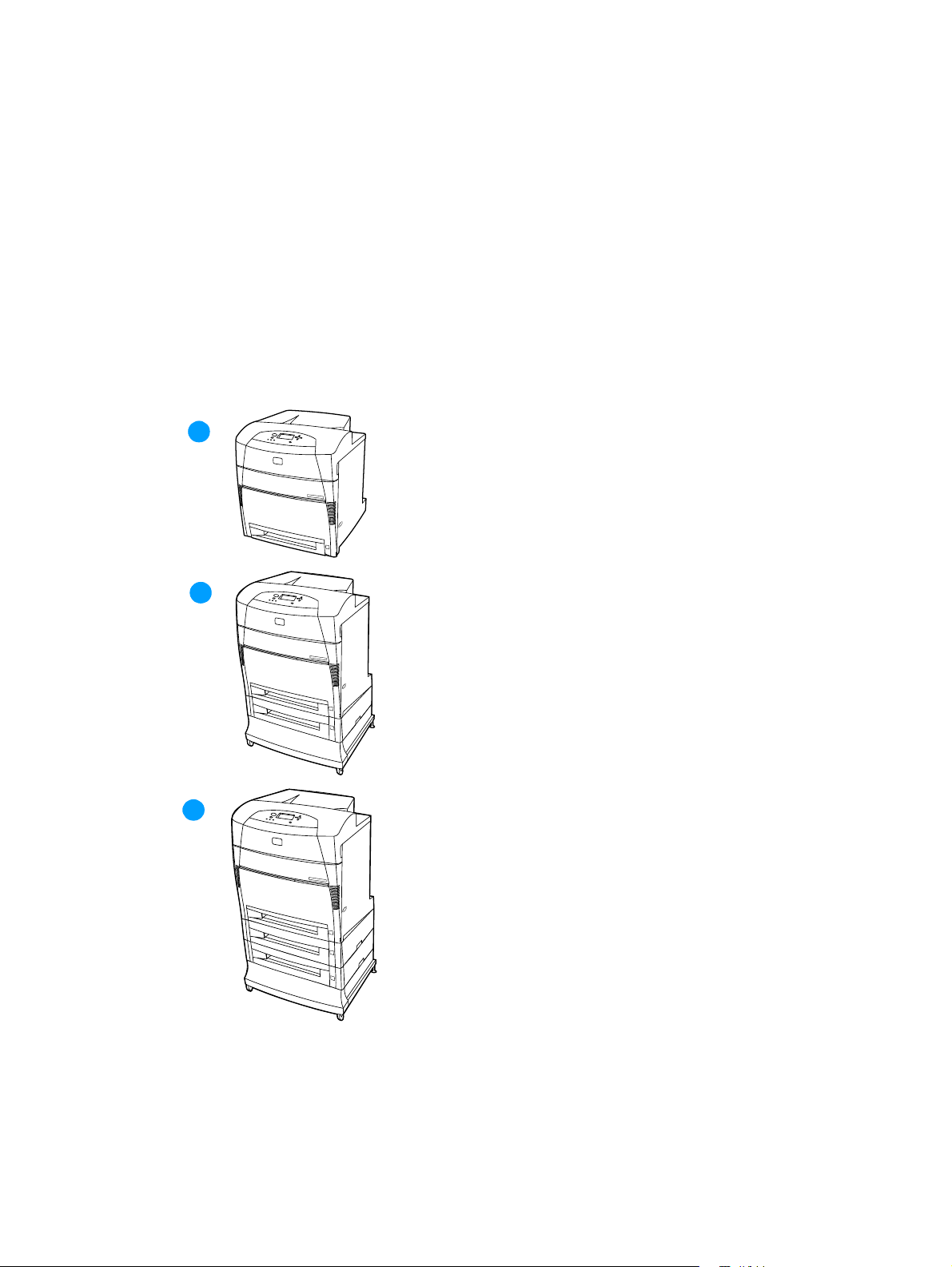
Printer features
The HP Color LaserJet 5500 series printer pictured in Figure 1-1 has five models.
● The HP Color LaserJet 5500 printer is the base model; it contains 96 MB of SDRAM.
● The HP Color LaserJet 5500n printer is the base model with an HP Jetdirect 615N print server
(network card). This model is available only in Europe.
● The HP Color LaserJet 5500dn printer is the base model with an HP Jetdirect 615N print
server (network card) and automatic 2-sided printing.
● The HP Color LaserJet 5500dtn printer is the base model with an HP Jetdirect 615N print
server (network card), automatic 2-sided printing, additional 500-sheet paper feeder, a stand,
and 160 MB of SDRAM.
● The HP Color LaserJet 5500hdn printer is the base model with an HP Jetdirect 615N print
server (network card), automatic 2-sided printing, two additional 500-sheet paper feeders, a
hard disk, a stand, and 160 MB of SDRAM.
1
2
3
Figure 1-1 HP Color LaserJet 5500 series printers
1 HP Color LaserJet 5500, 5500n, and 5500dn printers
2 HP Color LaserJet 5500dtn printer
3 HP Color LaserJet 5500hdn printer
12 Printer description ENWW
Page 21

This printer series combines the quality and reliability of Hewlett-Packard printers with the features
listed in Table 1-1.
Table 1-1 Printer features
Feature Description
Performance ● 21 pages per minute (ppm) on letter-sized paper, 22 ppm on
A4-sized paper.
● Prints on transparencies and glossy paper.
Memory
User interface
Supported
printer
personalities
Storage features
Environmental
features
● 96 megabytes (MB) of synchronous dynamic random access
memory (SDRAM) (160 MB i n the HP Color LaserJet 5500 dtn
and 5500hdn printers).
● Can be expanded to 416 MB.
● Optional hard disk drive (included with the HP Color LaserJet
5500hdn printer).
● Graphic display on con t rol panel .
● Enha nc ed He lp with ani mated graphics.
● Embedded Web server to access support and order supplies
(network-connected printers).
● HP PCL 6.
● HP PCL 5c.
● PostScript 3 emulation.
● Automatic language switching.
● Job retention (for printers with hard disks).
● Fonts and forms.
● Personal identification number (PIN) printing (for printers with
hard disks).
● PowerSave setting.
● High content of recyclable components and materials.
● Energy Star compliant.
Fonts
● 80 internal fonts available for both PCL and PostScript
emulation.
● 80 printer-matching screen fonts in TrueType™ format
available with the software solution.
● Supp orts fo rms and f on ts o n the d isk us ing HPWeb Je tad min.
ENWW Chapter 1 Printer description 13
Page 22

Table 1-1 Printer features
Feature Description
Paper handli ng
Accessories
● Prints on media from 76 by 127mm (3 by 5inches) up to
312 mm by 470 mm (12.3 by 18.5 inches).
● Prints on media with weights from 60 g/m
2
to 200 g/m2 (16 lb
bond to 53 lb bond).
● Prints on a w ide rang e of media typ es includin g glossy, labels,
overhead transparencies, and envelopes.
● Multiple gloss levels.
● A 500-s he et in put tr ay (Tray 2) that supports paper sizes from
148 by 210 mm (5.8 by 8.3inches) up to 297by 432 mm
(11.6 by 17 inches).
● Optional 500-sheet paper feeder that supports paper sizes
from 148 by 210 mm (5.8 by 8.3 inches) up to 297 by 432 mm
(11.6 by 17 inches); standard on HP Color LaserJet 5500dtn
and 5500hdn printers (the 5500hdn has two paper feeders).
● Automatic 2-sided printing on HP Color LaserJet 5500dn,
5500dtn, and 5500hdn printers.
● 250 -sh eet face-down output bin.
● Printer hard disk, whic h provi des stor age f or f onts an d macros
as well as job storage; standard on HP Color
LaserJet 5500hdn.
● Dual inline memory modules (DIMM).
● Printer stand (recommended for additional optional trays).
● Optional 500-sheet paper feeder that supports paper sizes
from 148 by 210 mm (5.8 by 8.3 inches) up to 297 by 432 mm
(11.6 by 17 inches); standard on HP Color LaserJet 5500dtn
and 5500hdn printers (the 5500hdn has two paper feeders).
● Fla sh DIMM .
● Fast InfraRed (FIR) pod.
Connectivity
Supplies
● Optional enhanced input/output (EIO) network card; standard
on HP Color LaserJet 5500n, 5500dn, 5500dtn, and 5500hdn
printers.
● FIR connection.
● HP Web Jetadmin software.
● Standard bidirectional parallel cable interface (IEEE-1284
compliant).
● Supp lies status page contai ns inf ormation on tone r lev el, pag e
count, and estimated pages remaining.
● No-shake cartridge design.
● Printer checks for authentic HP print cartridges at cartridge
installation.
● Internet-enabled supply-ordering capabilities (using
embedded Web server or printer Status and Alerts).
14 Printer description ENWW
Page 23
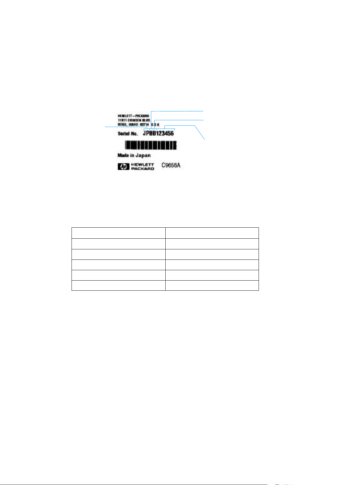
Identification
Model and serial numbers
The model number and serial numbers are listed on identification labels located on the rear of the
printer. The model number is alphanumeric, such as C9656A for the HP Color LaserJet 5500. The
serial number contains information about the country/region of origin, the printer version, production
code, and the production number of the printer (see Figure 1-2).
country/
region
of origin
Figure 1-2 Model and serial number information
printer version
production code
pproduction number
Table 1-2 Model names and numbers
Model name Model number
HP Color LaserJet 5500 C9656A
HP Color LaserJet 5500n C7131A
HP Color LaserJet 5500dn C9657A
HP Color LaserJet 5500dtn C9658A
HP Color LaserJet 5500hdn C9659A
ENWW Chapter 1 Printer description 15
Page 24
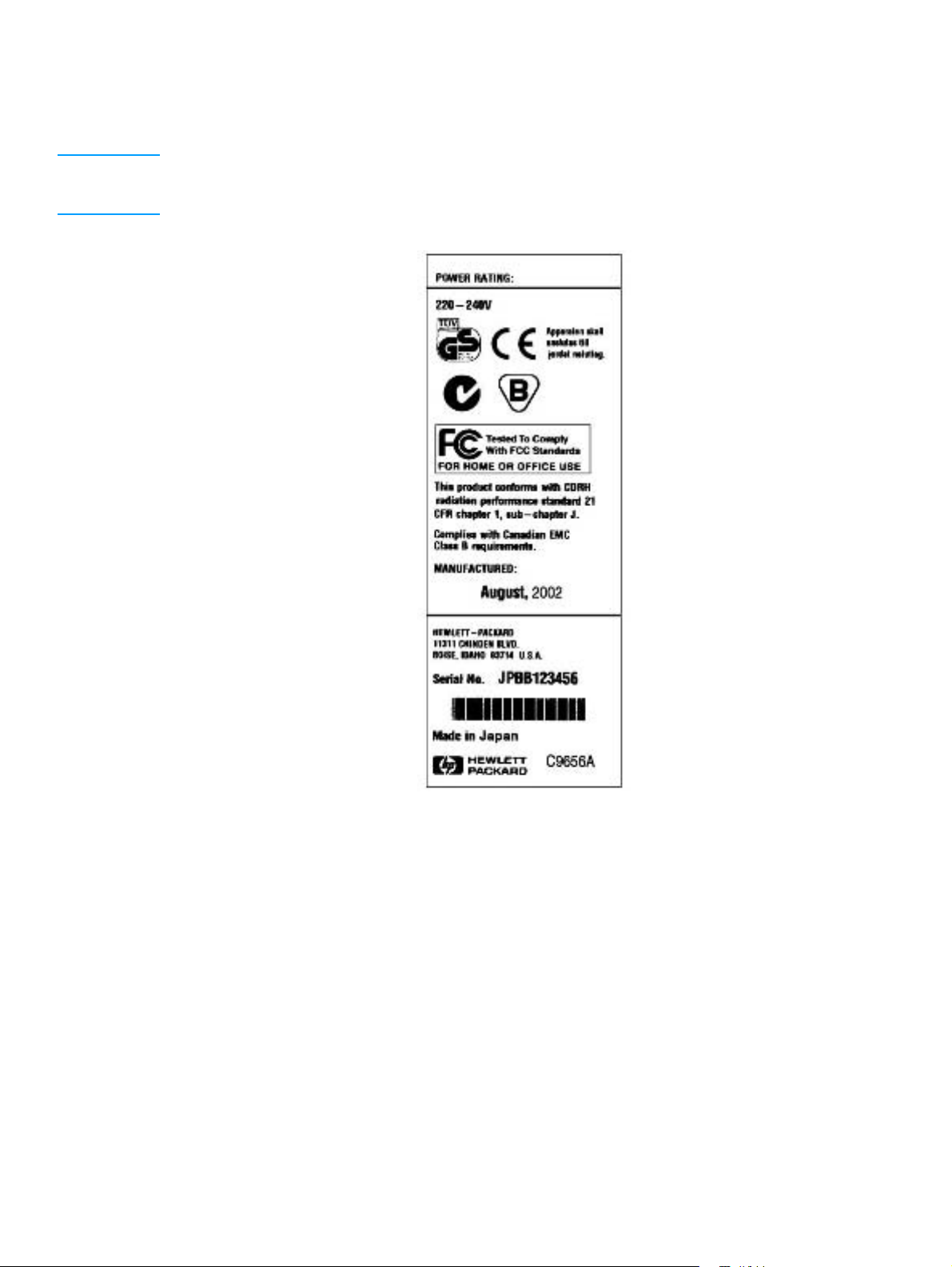
Power and regulatory information
The identification labels on the rear of the printer also contain power rating and regulatory
information as shown in Figure 1-3.
CAUTION Converting the voltage on the printer can damage the printer . Do not use any voltage other than the
operating voltage. Any attempt to convert operating voltages will void the product warranty (for
example, attempting to change a 110V printer to a 220V printer).
Figure 1-3 Sample label
16 Printer description ENWW
Page 25

Site requirements
The printer must be kept in a proper location to maintain the performance level that has been set at
the factory. In particular, be sure that the environment adheres to the specifications listed in this
chapter.
Below are recommendations for the printer location and placement.
Make sure the printer has the following:
● a well-ventilated, dust-free area
● a hard, level surface (not more than a 2° angle):
• for the HP Color LaserJet 5500, 5500n, and 5500dn, the surface must support 75 kg (163 lb)
• for the HP Color LaserJet 5500dtn, the surface must support 116 kg (256 lb)
• for the HP Color LaserJet 5500hdn, the surface must support 131 kg (289 lb)
● a level surface that supports all four corners of the 500-sheet paper feeder
● a constant temperature and humidity. (Do not install near water sources, humidifiers, air
conditioners, refrigerators, or other major appliances)
Make sure to keep the printer away from the following:
● direct sunlight, dust, open flames, or water
● the direct flow of exhaust from air ventilation systems
● magnets and devices that emit a magnetic field
● areas subject to vibration
● walls or other objects. There must be enough space around the printer for proper access and
ventilation. See Figure 1-4 on page 18.
ENWW Chapter 1 Printer description 17
Page 26
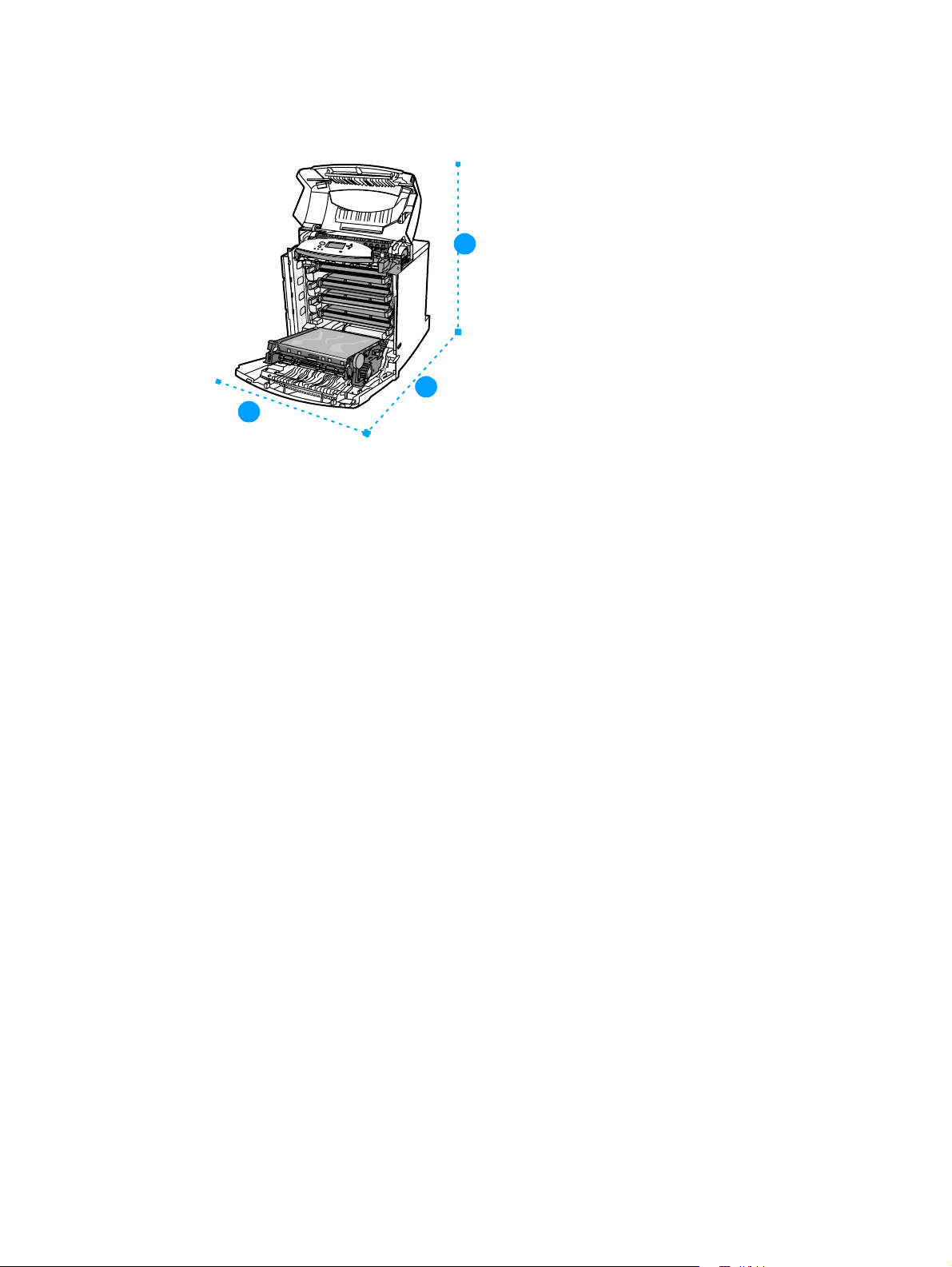
Space requirements
The printer must have the following amounts of space above and around it.
1
Figure 1-4 Space requirements (printer only)
1 628 mm (25 inches)
3
2
2 1090 mm (43 inches)
3 940 mm (37 inches)
500-sheet paper feeder dimensions
For each additional 500-sheet paper feeder installed, add the height from the list below to the
height of the printer.
● width = 578 mm (22.8 inches
● depth = 662 mm (26.2 inches)
● height = 132 mm (5.2 inches)
Printer stand dimensions
If the printer is on a stand, add the height from the list below to the total height. Also note that the
stand increases the overall width space requirement.
● width = 630 mm (24.8 inches)
● depth = 670 mm (26.5 inches)
● height = 202 mm (8.0 inches)
18 Printer description ENWW
Page 27
Electrical specifications
Table 1-3 lists the electrical specifications required to run the printer safely.
Table 1-3 Electrical specifications
Item 110-volt models 220-volt models
Power requirements 100-127 V (+/-10%)
50/60 Hz (+/- 2 Hz)
Power consumption
(LaserJet 5500)
During printing
During standby
During PowerSave
Off
Minimum recommended
circuit capacity for typical
product
* When the printer is in standby mode, it continues to consume a minimal amount of energy.
*
592 W
54 W
48 W
0 W
6 A 3 A
220-240 V (+/-10%)
50/60 Hz (+/- 2 Hz)
562 W
51 W
44 W
0 W
Note This information is preliminary and might not be current. Please see http://www.hp.com/support/lj5500
for current infor mat i o n .
Environmental specifications
Keep the printer within the environmental conditions shown in Table 1-4 for optimum performance.
Table 1-4 Environmental specifications
Item Operating
Temperature
Recommended
Allowed
Humidity
Recommended
Allowed
Altitude
Allowed 0 to 2600 m
17° to 25° C (63° to 77° F)
10° to 30° C (50° to 86° F)
30% to 70% RH
20% to 80% RH
(0 to 8530 ft)
ENWW Chapter 1 Printer description 19
Page 28
Supply storage requirements
The life of supplies is greatly affected by their storage environment. Use Table 1-5 to determine the
shelf life of stored supplies.
Table 1-5 Supply storage requirements
Item Storage time Storage condition
Temperature Normal (maximum of
Maximum temperature
change rate
Humidity Normal (maximum of
Atmospheric pressure 460 to 760 mm Hg (18.1 to 29.9 in Hg)
Storage time
1
The average storage time includes use time. Use cartridges within 2.5 years of the date code on the cartridge.
1
Printer specifications
Table 1-6 describes the dimensions of the printer.
Table 1-6 Printer dimensions
HP Color LaserJet
5500, 5500n, 5500dn
0° to 35° C (32° to 95° F)
2.5 years)
Severe (maximum of
18 days)
40° to 15° C (104° to 59° F) within 3 minutes
-20° to 25° C (-4° to 77° F) within 3 minutes
2.5 years)
Severe (maximum of
18 days)
2.5 years
High 35° to 40° C (95° to 104° F)
Low 0° to -20° C (32° to -4° F)
35% to 85% RH
High 85% to 95% RH
Low 10% to 35% RH
HP Color LaserJet
5500dtn
HP Color LaserJet
5500hdn
Height 640 mm (25.2 inches) 986 mm (38.8 inches) 1119 mm (44 inches)
Width 577 mm (22.7 inches) 630 mm (24.8 inches) 630 mm (24.8 inches)
Depth 704 mm (27.7 inches) 704 mm (27.7 inches) 704 mm (27.7 inches)
Weight 60 kg (132 lb) 113 kg (250 lb) 128 kg (283 lb)
Table 1-7 lists the acoustic emissions of the printer when it is printing and when it is in standby
mode.
Table 1-7 Acoustic emissions
HP Color LaserJet 5500
Sound power
Printing
PowerSave
Bystander (1m)
Printing
PowerSave
Per ISO 9296
= 6.5 bels(A) [65 dB (A)]
L
WAd
L
= 5.0 bels(A) [50dB (A)]
WAd
Per ISO 9296
L
= 49 dB (A)
PAm
L
= 33 dB(A)
PAm
Note These values are subject to change. See http://www.hp.com/support/lj5500 for current information.
Maximum duty cycle is 120,000 pages per month.
20 Printer description ENWW
Page 29
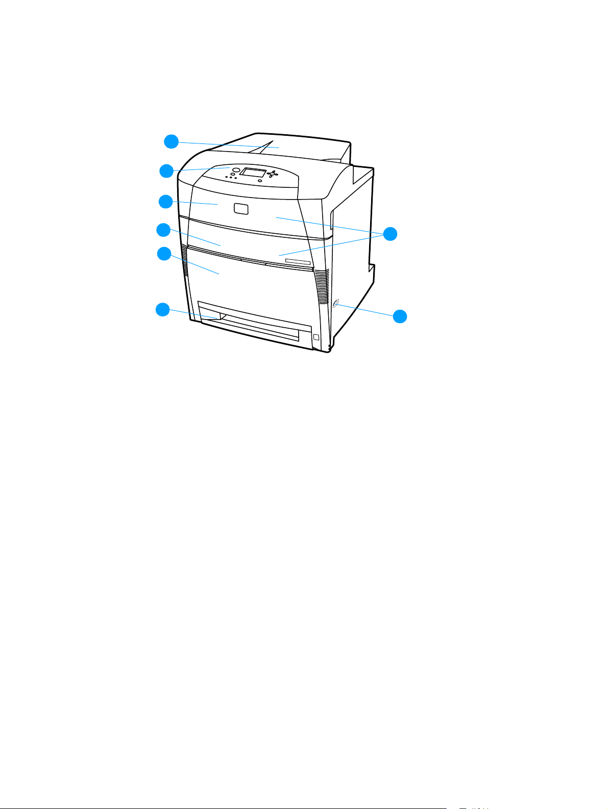
Printer assemblies
Figures 1-5 and 1-6 show the location of each major assembly in the printer. These assemblies are
described in Chapter 3.
1
2
3
4
5
6
Figure 1-5 Front view, HP Color LaserJet 5500 series
1 output bin
2 printer control panel
3 top cover
4 front cover
5 Tray 1
6 Tray 2 (500-sheet standard tray)
7 on/off switch
8
7
8 access to print cartridges, transfer unit, and fuser
ENWW Chapter 1 Printer description 21
Page 30
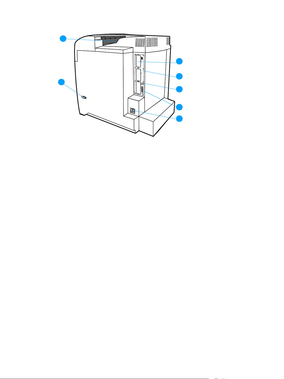
1
2
Figure 1-6 Rear view, HP Color LaserJet 5500 series
1 output bin
2 on/off switch
3
4
5
6
7
3 EIO connection (quantity 3)
4 Formatter
5 FIR (Fast InfraRed) connection
6 parallel connection
7 power connection
22 Printer description ENWW
Page 31

Media requirements
Selecting print media
You can use many types of paper and other print media with this printer. This section provides
guidelines and specifications for selecting and using different print media.
Before purchasing any media or specialized forms in quantity, verify that your paper supplier obtains
and understands the print media requirements specified in the HP LaserJet Family Print Media
Guide. The guide is available through Hewlett-Packard Customer Support (HPCS). See page 43 for
ordering information.
It is possible that media could meet all of the guidelines in this chapter and still not print satisfactorily .
This may be a result of abnormal characteristics of the printing environment or of other variables over
which Hewlett-Packard has no control (for example, extremes in temperature and humidity).
Hewlett-Packard recommends testing any media before buying it in large quantities.
CAUTION Using media that does not conform to the specifications listed here and in the HP LaserJet F amily Prin t
Media Guide can cause problems that require service. This service is not covered by the
Hewlett-Packard warranty or service agreements.
Media specifications
For optimum results, use conventional 75 g/m2 (20 lb) xerographic paper. Verify that the paper is of
good quality and is free of cuts, nicks, tears, spots, loose particles, dust, wrinkles, curls, or bent
edges. Avoid fanning the print media before loading it into the paper trays.
Paper orientation
Normal orientation loads long-side first into the printer. This is the preferred orientation because it
allows for longer supply life and increased printer speed. However, some paper sizes can be loaded
short-side first. This orientation is called “rotated.” Paper that can be fed into the printer using the
rotated, short-side first orientation has “-R” after the paper size. These paper sizes are Letter-R,
A4-R, A5-R, and B5-R.
ENWW Chapter 1 Printer description 23
Page 32

Supported media weights and sizes
Table 1-8 and Table 1-9 show the media types and sizes supported by the printer and the printer
accessories.
Table 1-8 Tray 1 (multi-purpose tray) supported media specifications
Media type Dimensions Weight or
thickness
Standard size
paper/cardstock
(Letter/A4, Legal,
Executive, JIS B5, B5-R,
A5, A5-R, 11 by 17
1
, A3)
Minimum size
paper/cardstock
Maximum size
paper/cardstock
Standard size
glossy paper
(Letter/A4, Letter-R,
A4-R, Legal, Executive,
JIS B5, B5-R, A5, A5-R,
11 by 17, A3)
Minimum size
glossy paper
Maximum size
glossy paper
Standard size
transparencies
(Letter/A4, Letter-R,
A4-R, Legal, Executive,
JIS B5, B5-R, A5, A5-R,
11 by 17, A3)
Minimum size
transparencies
Maximum size
transparencies
Standard size tough
paper
(Letter/A4, Letter-R,
A4-R, Legal, Executive,
JIS B5, B5-R, A5, A5-R,
11 by 17, A3)
Minimum size tough
paper
Maximum size tough
paper
Envelope (Co m 10,
Monarch, C5, DL, B5)
76 by 127 mm
(3 by 5 inches)
312 by 470 mm
(12.3 by 18.5 inches)
76 by 127 mm
(3 by 5 inches)
312 by 470 mm
(12.3 by 18.5 inches)
76 by 127 mm
(3 by 5 inches)
312 by 470 mm
(12.3 by 18.5 inches)
76 by 127 mm
(3 by 5 inches)
312 by 470 mm
(12.3 by 18.5 inches)
60 to 200 g/m
(16 to 53 lb bond)
60 to 200 g/m
(16 to 53 lb bond)
60 to 200 g/m
(16 to 53 lb bond)
75 to 163 g/m
(20 to 43 lb bond)
75 to 163 g/m
(20 to 43 lb bond)
75 to 163 g/m
(20 to 43 lb bond)
0.12 to 0.13 mm
thick
(4.7 to 5.5 mils thick)
0.12 to 0.13 mm
thick
(4.7 to 5.5 mils thick)
0.12 to 0.13 mm
thick
(4.7 to 5.5 mils thick)
0.10 to 0.13 mm
thick
(4 to 5.5 mils thick)
0.10 to 0.13 mm
thick
(4 to 5.5 mils thick)
0.10 to 0.13 mm
thick
(4 to 5.5 mils thick)
75 to 105 g/m
(20 to 28 lb bond)
Capacity
2
100 sheets of 75 g/m
(20 lb) paper
2
100 sheets of 75 g/m
(20 lb) paper
2
100 sheets of 75 g/m
(20 lb) paper
2
Maximum stack height:
10 mm (0.4 inches)
2
Maximum stack height:
10 mm (0.4 inches)
2
Maximum stack height:
10 mm (0.4 inches)
Maximum stack height:
10 mm (0.4 inches)
Maximum stack height:
10 mm (0.4 inches)
Maximum stack height:
10 mm (0.4 inches)
Maximum stack height:
10 mm (0.4 inches)
Maximum stack height:
10 mm (0.4 inches)
Maximum stack height:
10 mm (0.4 inches)
2
20 envelopes
(10 mils thick)
2
2
2
24 Printer description ENWW
Page 33

Table 1-8 Tray 1 (multi-purpose tray) supported media specifications (continued)
Media type Dimensions Weight or
thickness
Standard size label
(Letter/A4, Letter-R,
A4-R, Legal, Executive,
JIS B5, B5-R, A5, A5-R,
11 by 17, A3)
Minimum size label 76 by 127 mm
(3 by 5 inches)
Maximum size labe l 312 by 470 mm
(12.3 by 18.5 inches)
1
11 by 17 inch, Ledger, and Tabloid sizes are all the same.
Table 1-9 Tray 2, Tray 3, and Tray 4 supported media specifications
Media type Dimensions Weight or
thickness
Standard size paper
(Letter/A4, Letter-R,
A4-R, Legal, Executive,
JIS B5, B5-R, A5, A5-R,
11 by 17, A3)
Minimum size paper 148 by 210 mm
(5.8 by 8.3 inches)
60 to 163 g/m
(16 to 43 lb bond)
60 to 163 g/m
(16 to 43 lb bond)
2
2
Capacity
Maximum stack height:
10 mm (0.4 inches)
Maximum stack height:
10 mm (0.4 inches)
Maximum stack height:
10 mm (0.4 inches)
1
Capacity
500 sheets of 75 g/m
(20 lb) paper
500 sheets of 75 g/m
(20 lb) paper
2
2
Maximum size
paper/cardstock
Standard size
glossy paper
(Letter/A4, Letter-R,
A4-R, Legal, Executive,
JIS B5, B5-R, A5, A5-R,
11 by 17, A3)
Minimum size
glossy paper
Maximum size
glossy paper
Standard size
transparencies
(Letter/A4, Letter-R,
A4-R, Legal, Executive,
JIS B5, B5-R, A5, A5-R,
11 by 17, A3)
Minimum size
transparencies
Maximum size
transparencies
297 by 432 mm
(11.7 by 17 inches)
148 by 210 mm
(5.8 by 8.3 inches)
297 by 432 mm
(11.7 by 17 inches)
148 by 210 mm
(5.8 by 8.3 inches)
297 by 432 mm
(11.7 by 17 inches)
60 to 163 g/m
2
(16 to 43 lb bond)
75 to 163 g/m
2
(20 to 43 lb bond)
60 to 163 g/m
2
(16 to 43 lb bond)
60 to 163 g/m
2
(16 to 43 lb bond)
0.12 to 0.13 mm
thick
(4.7 to 5.5 mils thick)
0.12 to 0.13 mm
thick
(4.7 to 5.5 mils thick)
0.12 to 0.13 mm
thick
(4.7 to 5.5 mils thick)
100 sheets of 75 g/m
2
(20 lb) paper
200 sheets
200 sheets
200 sheets
100 sheets of 0.13 mm
(5.5 mils) thick
100 sheets of 0.13 mm
(5.5 mils) thick
100 sheets of 0.13 mm
(5.5 mils) thick
ENWW Chapter 1 Printer description 25
Page 34

Table 1-9 Tray 2, Tray 3, and Tray 4 supported media specifications
1
Media type Dimensions Weight or
Capacity
thickness
Standard size Tough
paper
(Letter/A4, Letter-R,
A4-R, Legal, Executive,
JIS B5, B5-R, A5, A5-R,
11 by 17, A3)
Minimum size Tough
paper
Maximum size Tough
paper
Standard size label
(Letter/A4, Letter-R,
A4-R, Legal, Executive,
JIS B5, B5-R, A5, A5-R,
11 by 17, A3)
Minimum size label 148 by 210 mm
Maximum size label 297 by 432 mm
1
Trays 2, 3, and 4 use “Custom” size specifically for B5 ISO. Trays 2, 3, and 4 do not support the range of custom
sizes available in Tray 1.
148 by 210 mm
(5.8 by 8.3 inches)
297 by 432 mm
(11.7 by 17 inches)
(5.8 by 8.3 inches)
(11.7 by 17 inches)
0.10 to 0.13 mm
thick
(4 to 5.5 mils thick)
0.10 to 0.13 mm
thick
(4 to 5.5 mils thick)
0.10 to 0.13 mm
thick
(4 to 5.5 mils thick)
100 sheets of 0.13 mm
(5.5 mils) thick
100 sheets of 0.13 mm
(5.5 mils) thick
100 sheets of 0.13 mm
(5.5 mils) thick
Maximum stack height:
50 mm (2 inches)
Maximum stack height:
10 mm (0.4 inches)
Maximum stack height:
10 mm (0.4 inches)
Media specifications for 2-sided (duplex) printing
For automatic 2-sided printing, you can use any of the following standard-size paper in weights
from 60 to 120 g/m
● Letter/A4
● A3
● Legal
● Executive
● JIS B5
● A5
● 11 by 17 inch
Note The printer automatically prints on paper weights up to 163 g/m2. However , automatic 2-sided printing
on weights above the maximum value noted above can produce unexpected results.
Automatic 2-sided printing does not support rotated (short-edge first) orientation.
For manual 2-sided printing, you can use any of the supported paper sizes listed for printing from
Tray 1.
2
(16 to 32 lb bond):
26 Printer description ENWW
Page 35

Media to avoid
This printer can handle many types of media. Using media outside the printer’s specifications will
cause a loss of print quality and increase the chance of paper jams occurring.
● Do not use paper that is too rough.
● Do not use paper with cutouts or perforations other than standard 3-hole punched paper.
● Do not use multipart forms.
● Do not use paper that has already been printed on or fed through a photocopier or printer.
● Do not use paper with a watermark if you are printing solid patterns.
Media that may cause damage to the printer
In rare circumstances media can damage the printer. To prevent possible damage, do not use the
following media:
● Do not use paper that is embossed or coated unless it is specifically recommended for use in this
printer.
● Do not use paper with irregularities such as tabs or staples.
● Do not use letterhead paper with low temperature dyes or thermography. Preprinted forms or
letterhead must use inks that can tolerate temperatures of 190° C (374° F) for 0.1 second.
● Do not use any media that produces hazardous emissions, or that melts, offsets, or discolors
when exposed to 190° C (374° F) for 0.1 second.
● Do not use transparencies designed for use with Inkjet printers or other low temperature printers.
Use only transparencies that are specified for use with HP Color LaserJet printers.
Printing on special media
Use these guidelines when printing on special types of media.
● For optimum results, use conventional 75 g/m
● Verify that the paper is of good quality and free of cuts, nicks, tears, spots, loose particles, dust,
wrinkles, curls, or bent edges.
Transparencies
When printing on transparencies, use the following guidelines.
● Handle transparencies using the edges. Oils from your fingers can remain on the transparency
and can cause print quality problems.
● Use only overhead transparencies recommended for use in this printer. Hewlett-Packard
recommends using HP Color LaserJet Transparencies with this printer. HP products are
designed to work together for optimum printing results. Table 1-10 describes the recommended
specifications for transparencies.
● In either the software application or the driver, select Transparency as the media type. Or, print
from a tray that is configured for transparencies.
CAUTION T ransparencies not designed for LaserJet printing will melt in the printer, causing damage to the printer .
2
(20 lb) xerographic paper.
ENWW Chapter 1 Printer description 27
Page 36

Table 1-10 Printing on transparencies
Description Specifications
Electrical surface
resistivity
Fusing compatibility Materials must not discolor, melt, offset, or release
Caliper (thickness ) 0.12 mm (0.0048 in) to 0.13 mm (0.0052 in)
2 to 15 by 10 ohms per square inch
hazardous emissions when heated to 190°C
(374° F) for 0.1 second.
Glossy paper
● In either the software application or the driver, select Glossy as the media type for media
lighter than 105 g/m
(28 lb bond), or print from a tray that is configured for glossy paper.
● You can also use the printer control panel to set the media type to GLOSS for the input tray you
are using.
● Because this setting affects all print jobs, it is important to return the printer to its original
settings once your job has printed. See the section in the online user guide on configuring input
trays.
Note Hewlett-Packard recommends using HP Color LaserJet Soft Gloss paper with this printer. HP
products are designed to work together for optimum printing results. If HP Color LaserJet Soft Gloss
paper is not used with this printer, print quality may be compromised.
2
(28 lb bond), select Heavy Glossy for media heavier than 105 g/m2
Colored paper
● Colored paper should be of the same high quality as white xerographic paper.
● Pigments used must be able to withstand the printer’s fusing temperature of 190° C (374° F) for
0.1 second without deterioration.
● Do not use paper with a colored coating that was added after the paper was produced.
● The printer creates colors by printing patterns of dots, overlaying and varying their spacing to
produce various colors. Varying the shade or color of your paper will affect the shades of your
printed colors.
Heavy paper
● Any of the trays will print most heavy media that does not exceed 163 g/m
● For optimum results when printing on heavy paper, use the printer control panel to set the
media type for the tray to
● Use card stock only in Tray 1 (163 g/m
● In either the software application or the driver, select Heavy or Cardstock as the media type,
HEAVY (106 g/m
2
to 163 g/m2).
2
to 200 g/m2).
or print from a tray that is configured for heavy paper.
● Because this setting affects all print jobs, it is important to return the printer to its original
settings once your job has printed. See the section in the online user guide on configuring input
trays.
CAUTION In general, do not use paper that is heavier than the recommended specification for this printer. Doing
so can cause misfeeds, jams, inferior print quality , and excessive mechanical wear. Howe v er , some
heavier media types, such as HP Cover Stock, can be safely used. See T able 1-8 for supported paper
types and sizes.
28 Printer description ENWW
2
(47 lb bond).
Page 37

Envelopes
Envelopes can be printed only from Tray 1. Set the tray’s media size to the specific envelope size. For
information about loading envelopes, see the section in the online user guide about loading
envelopes into Tray 1.
Adhering to the following guidelines will help ensure proper printing on envelopes and help prevent
printer jams:
● Do not load more than 20 envelopes into Tray 1.
● The weight rating of envelopes should not exceed 105 g/m
● Envelopes should be flat.
● Do not use e nvelopes with windows or clasps.
● Envelopes must not be wrinkled, nicked, or otherwise damaged.
● Envelopes with peel-off adhesive strips must use adhesives that can withstand the heat and
pressures of the printer’s fusing process.
● Envelopes should be loaded face-down and with the top of the envelope to the left, and the short
edge feeding into the printer first.
Note In high humidity environments, envelopes should be printed long-edge first to prevent them from sealing
during printing. For long-edge printing, envelopes should be loaded long-edge first, face-down. See
the section in the online user guide about loading envelopes in Tray 1.
2
(28 lb).
CAUTION T o prevent sev ere printer damage, do not use envelopes that have windows, clasps, snaps, or synthetic
materials.
Labels
Note To print labels, set the tray’s media type to LABELS in the printer control panel.
When printing labels, use the following guidelines:
● Verify that the label’s adhesive material can tolerate temperatures of 190° C (374° F) for 0.1
second.
● V erify that adhesive material is not exposed between the labels. Exposed areas can cause labels
to peel off during printing, which can cause printer jams. Exposed adhesive can also cause
damage to printer components.
● Do not re-feed a sheet of labels.
● Verify that labels lie flat.
● Do not use labels that are wrinkled, bubbled, or otherwise damaged.
HP LaserJet Tough paper
When printing on HP LaserJet Tough paper, use the following guidelines:
● Handle HP LaserJet Tough paper using the edges. Oils from your fingers deposited on HP
LaserJet Tough paper can cause print quality problems.
● Use only Hewlett-Packard LaserJet Tough paper with this printer. HP products are designed to
work together for optimum printing results.
● In either the software application or the driver, select Tough Paper as the media type, or print
from a tray that is configured for HP LaserJet Tough paper.
CAUTION Transparent media that are not designed for LaserJet printing will melt in the printer, causing damage
to the printer.
ENWW Chapter 1 Printer description 29
Page 38

Preprinted forms and letterhead
Observe the following guidelines for best results with preprinted forms and letterhead:
● Forms and letterhead must be printed with heat-resistant inks that will not melt, vaporize, or
release hazardous emissions when subjected to the printer’s fusing temperature of
approximately 190° C (374° F) for 0.1 second.
● Inks must be non-flammable and should not adversely affect any printer rollers.
● Forms and letterhead should be sealed in a moisture-proof wrapping to prevent changes
during storage.
● Before you load preprinted paper such as forms and letterhead, verify that the ink on the paper
is dry. During the fusing process, wet ink can come off of preprinted paper.
● When duplex printing, load preprinted forms and letterhead into Tray 2, Tray 3, and Tray 4
face-down with the top edge of the page to the left. Load preprinted forms and letterhead into
Tray 1 face-up with the top edge of the page to the left.
Recycled paper
This printer supports the use of recycled paper. Recycled paper must meet the same specifications
as standard paper; refer to the HP LaserJet Printer Family Print Media Guide , available through
HP Direct. See the online user guide for ordering information. Hewlett-Packard recommends that
recycled paper contain no more than 5 percent groundwood.
30 Printer description ENWW
Page 39

Weight equivalence table
Table 1-11 shows equivalent weights for different grades of paper. A boldface type value indicates a
commonly available standard weight for that grade.
Note Text and book grades marked with an asterisk (*) actually calculate to 51, 61, 71, and 81 but are
rounded to standard book or text weights of 50, 60, 70, and 80.
Table 1-11 Weight equivalence table
Bond
weight
(17 by 22
inches)
Text/Boo
k weight
(25 by 38
inches)
Cover
weight
(20 by
26
inches)
16# 41# 22# 27# 33# 37# 60 g/m
17# 43# 24# 29# 35# 39# 64 g/m
20# 50# * 28# 34# 42# 46# 75 g/m
21# 54# 30# 36# 44# 49# 80 g/m
24# 60# * 33# 41# 50# 55# 90 g/m
27# 68# 37# 45# 55# 61# 100 g/m
28# 70# * 39# 49# 58# 65# 105 g/m
29# 74# 41# 50# 61# 68# 110 g/m
32# 80# * 44# 55# 67# 74# 120 g/m
36# 90# 50# 62# 75# 83# 135 g/m
39# 100# 55# 67# 82# 91# 148 g/m
40# 101# 55# 68# 83# 92# 150 g/m
43# 110# 60# 74# 90# 100# 163 g/m
45# 115# 63# 77# 94# 104# 170 g/m
47# 119# 65# 80# 97# 108# 176 g/m
51# 128# 70# 86# 105# 117# 190 g/m
53# 134# 74# 90# 110# 122# 199 g/m
54# 137# 75# 93# 113# 125# 203 g/m
58# 146# 80# 98# 120# 133# 216 g/m
65# 165# 90# 111# 135# 150# 244 g/m
66# 169# 92# 114# 138# 154# 250 g/m
67# 171# 94# 115# 140# 155# 253 g/m
70# 178# 98# 120# 146# 162# 264 g/m
72# 183# 100# 123# 150# 166# 271 g/m
Bristol
weight
(22.5 by
28.5
inches)
Index
weight
(25.5 by
30.5
inches)
Tag
weight
(24 by 36
inches)
Metric
weight
2
2
2
2
2
2
2
2
2
2
2
2
2
2
2
2
2
2
2
2
2
2
2
2
ENWW Chapter 1 Printer description 31
Page 40

Environmental product stewardship program
Protecting the environment
Hewlett-Packard Company is committed to providing quality products in an environmentally sound
manner. This product has been designed with several attributes to minimize impacts on the
environment.
Ozone production
This product generates no appreciable ozone gas (O3).
Energy consumption
Energy usage drops significantly while in PowerSave mode, which saves natural resources and
saves money without affecting the high performance of this printer. This product qualifies for
ENERGY STAR
office products.
®
, which is a voluntary program to encourage the development of energy-efficient
ENERGY STAR
Protection Agency. As an ENERGY STAR
Company has determined that this product meets ENERGY STAR
Guidelines for energy efficiency. For more information,
see http://www.energystar.gov/
®
is a U.S. registered service mark of the U.S. Environmental
.
®
partner, Hewlett-Packard
®
Paper use
This product’s optional automatic duplex f eature (2-sided printing) can reduce paper usage and the
resulting demands on natural resources.
Plastics
Plastic parts over 25 grams have markings according to international standards that enhance the
ability to identify plastics for recycling purposes at the end of the product’s lif e.
HP LaserJet printing supplies
In many countries/regions, this product’s printing supplies (print cartridges, fuser , and transfer unit)
can be returned to HP through the HP Printing Supplies Returns and Recycling Program. An easy
to use and free takeback program is available in over 48 countries/regions. Multi-lingual program
information and instructions are included in every new HP LaserJet print cartridge and supplies
package.
32 Printer description ENWW
Page 41

HP printing supplies returns and recycling program information
Since 1990, the HP Printing Supplies Returns and Recycling Program has collected millions of used
LaserJet printer cartridges that otherwise might have been discarded in the world’s landfills. The HP
LaserJet printer cartridges and supplies are collected and bulk-shipped to our resource and recovery
partners, who disassemble the cartridges. After a thorough quality inspection, selected parts are
reclaimed for use in new cartridges. Remaining materials are separated and converted into raw
materials for use by other industries to make a variety of useful products.
● U.S. returns—For a more environmentally responsible return of used cartridges and supplies,
HP encourages the use of bulk returns. Simply bundle two or more cartridges together and use
the single, pre-paid, and pre-addressed UPS label that is supplied in the package. For more
information in the U.S., call 1-800-340-2445 or visit the HP LaserJet Supplies website at
http://www.hp.com/go/recycle
● Non-U.S. recycling returns—Non-U.S. customers should call the local HP Sales and Service
Office or visit the http://www.hp.com/go/recycle
.
website for further information regarding
availability of the HP Supplies Returns and Recycling Program.
Recycled paper
This product is capable of using recycled papers when the paper meets the guidelines outlined in the
Print Media Guide. This product is suitable for the use of recycled paper according to DIN 19309.
Material restrictions
This product does not contain batteries.
This product does not contain added mercury.
This product contains lead in solder.
For recycling information, contact http://www.hp.com/go/recycle
to the Elec tronics Industrie s Alliance website http://www.eiae.org
, contact your local authorities, or go
.
Extended warranty
HP SupportPack provides coverage for the HP hardware product and all HP-supplied internal
components. The hardware maintenance covers a 1 to 5 year period from date of the HP product
purchase. The customer must purchase HP SupportPack within 90 days of the HP product purchase.
For more information, contact the HP Customer Care Service and Support group.
Spare parts and supplies availability
Spare parts and supplies for this product will be available for at least five years after production has
stopped.
For more information
On HP’s environmental programs, including:
● Product environmental profile sheet for this and many related HP products
● HP’s commitment to the environment
● HP’s environmental management system
● HP’s end-of-life product return and recycling program
● Material Safety Data Sheets
See http://www.hp.com/go/environment
http://www.hp.com/hpinfo/community/environment/
ENWW Chapter 1 Printer description 33
or
.
Page 42

Regulatory statements
FCC Regulations
This equipment has been tested and found to comply with the limits for a Class B digital device,
pursuant to Part 15 of the FCC rules.These limits are designed to provide reasonable protection
against harmful interference in a residential installation. This equipment generates, uses, and can
radiate radio frequency energy. If this equipment is not installed and used in accordance with the
instructions, it may cause harmful interference to radio communications. However, there is no
guarantee that interference will not occur in a particular installation. If this equipment does cause
harmful interference to radio or television reception, which can be determined by turning the
equipment off and on, the user is encouraged to try to correct the interference by one or more of
the following measures:
● Reorient or relocate the receiving antenna.
● Increase separation between equipment and receiver.
● Connect equipment to an outlet on a circuit different from that to which the receiver is located.
● Consult your dealer or an experienced radio/TV technician.
Note Any changes or modifications to the printer that are not expressly approved by HP could void the
user’s authority to operate this equipment.
Use of a shielded interface cable is required to comply with the Class B limits of Part 15 of FCC rules.
34 Printer description ENWW
Page 43

Safety information
Laser safety statement
The Center for Devices and Radiological Health (CDRH) of the U.S. Food and Drug Administration
has implemented regulations for laser products manufactured since 1 August 1976. Compliance is
mandatory for products marketed in the United States. The printer is certified as a “Class 1” laser
product under the U.S. Department of Health and Human Services (DHHS) Radiation Performance
Standard according to the Radiation Control for Health and Safety Act of 1968. Since radiation
emitted inside the printer is completely confined within protective housings and external covers, the
laser beam cannot escape during any phase of normal user operation.
WARNING! Using controls, making adjustments, or performing procedures other than those specified in this guide
may result in exposure to hazardous radiation.
Material Safety Data Sheet
Material Safety Data Sheets (MSDS) can be obtained by contacting the HP LaserJet Supplies
website at http://www.hp.com/go/msds
Toner safety
.
Hewlett-Packard encourages responsible disposal of HP LaserJet printer supply items through its
Environmental Collection Program. For details on this program, see the recycling instruction guide
enclosed with each supply item.
Note In case of toner spills, skin and clothing are best cleaned by removing as much toner as possible with
a dry tissue, then washing with cold water. Hot water causes toner to permanently set into clothing.
Canadian DOC regulations
Complies with Canadian EMC Class B requirements.
«Conforme á la classe B des normes canadiennes de compatibilité électromagnétiques. «CEM».»»
EMI statement (Korea)
Figure 1-7 EMI statement for Korea
ENWW Chapter 1 Printer description 35
Page 44

VCCI statement (Japan)
Figure 1-8 VCCI statement for Japan
36 Printer description ENWW
Page 45

Laser statement for Finland
LASERTURVALLISUUS
Luokan 1 laserlaite
Klass 1 Laser Apparat
HP Color LaserJet 5500, 5500n, 5500dn, 5500dtn, 5500hdn laserkirjoitin on käyttäjän kannalta
turvallinen luokan 1 laserlaite. Normaalissa käytössä kirjoittimen suojakotelointi estää lasers äteen
pääsyn laitteen ulkopuolelle.
Laitteen turvallisuusluokka on määritetty standardin EN 60825-1 (1994) mukaisesti.
VAROITUS !
Laitteen käyttäminen muulla kuin käyttöohjeessa mainitulla tavalla saattaa altistaa käyttäjän
turvallisuusluokan 1 ylittävälle näkymättömälle lasersäteilylle.
VARNING !
Om apparaten används på annat sätt än i bruksanvisning specificerats, kan användaren utsättas för
osynlig laserstrålning, som överskrider gränsen för laserklass 1.
HUOLTO
HP Color LaserJet 5500, 5500n, 5500dn, 5500dtn, 5500hdn kirjoittimen sisällä ei ole käyttäjän
huollettavissa olevia kohteita. Laitteen saa avata ja huoltaa ainoastaan sen huoltamiseen koulutettu
henkilö. Tällaiseksi huoltotoimenpiteeksi ei katsota väriainekasetin vaihtamista, paperiradan
puhdistusta tai muita käyttäjän käsikirjassa lueteltuja, käyttäjän teht äväksi tarkoitettuja ylläpitotoimia,
jotka voidaan suorittaa ilman erikoistyökaluja.
VARO !
Mikäli kirjoittimen suojakotelo avataan, olet alttiina näkymättömälle lasersäteilylle laitteen ollessa
toiminnassa. Älä katso säteeseen.
VARNING !
Om laserprinterns skyddshölje öppnas då apparaten är i funktion, utsättas användaren för osynlig
laserstrålning. Betrakta ej strålen.
Tiedot laitteessa käytettävän laserdiodin säteilyominaisuuksista:
Aallonpituus 775-7 95 nm
Teho 5 mW
Luokan 3B laser
ENWW Chapter 1 Printer description 37
Page 46

Declaration of Conformity
according to ISO/IEC Guide 22 and EN 45014
Manufacturer’s Name:
Manufacturer’s Address:
declares that the product
Hewlett-Packard Company
11311 Chinden Boulevard
Boise, Idaho 83714-1021 USA
Product Name:
Regulatory Model Number:
Product Options:
conforms to the following Product Specifications:
Safety: IEC 60950:1991+A1+A2+A3+A4 / EN 60950:1992+A1+A2+A3+A4+A11
IEC 60825-1:1993 +A1 / EN 60825-1 +A11 Class 1 Laser/LED Product
GB4943-1995
EMC: CISPR 22:1993 +A1 +A2 / EN 55022:1994 +A1 +A2 Class B
EN 61000-3-2:1995 / A14
EN 61000-3-3:1995
EN 55024: 1998
FCC Title 47 CFR, Part 15 Class B2/ ICES-002, Issue 3 / GB9254-1998
AS / NZS 3548:1995 +A1 +A2
Supplementary Information:
The product herewith complies with the requirements of the EMC Directive 89/336/EEC and the Low Voltage
Directive 73/23/EEC, and carries the CE-Marking accordingly:
1
The product was tested in a typical configuration with Hewlett-Packard Personal Computer Systems.
2
This Device complies with Part 15 of the FCC Rules. Operation is subject to the following two Conditions:
(1) this device may not cause harmful interference, and (2) this device must accept any interference received,
including interference that may cause undesired operation.
*
) This product includes LAN (Local Area Network) options. When the interface cable is attached to LAN
connectors, the product meets the requirements of EN55022 Class A in which case the following applies:
“Warning” This is a Class A product. In a domestic environment this product may cause radio interference
in which case the user may be required to take adequate measures”.
Hewlett-Packard Company
Boise, Idaho 83713 USA
12 March, 2002
For regulatory topics only:
Australia Contact: Product Regulations Manager, Hewlett-Packard Australia Ltd., 31-41 Joseph Street,
Blackburn, Victoria 3130, Australia
European Contact: Your Local Hewlett-Packard Sales and Service Office or Hewlett-Packard Gmbh,
Department HQ-TRE / Standards Europe, Herrenberger Straße 130, D-71034 Böblingen
(FAX: +49-7031-14-3143)
USA Contact: Product Regulations Manager, Hewlett-Packard Company, PO Box 15, Mail Stop 160,
Boise, ID 83707-0015 (Phone: 208-396-6000)
HP Color LaserJet 5500 series
Including: 500-sheet paper feeder
BOISB-0202-00
ALL
1
38 Printer description ENWW
Page 47

2
Service approach
Chapter contents
Service approach . . . . . . . . . . . . . . . . . . . . . . . . . . . . . . . . . . . . . . 40
Parts and supplies. . . . . . . . . . . . . . . . . . . . . . . . . . . . . . . . . . . . . . 41
Ordering parts . . . . . . . . . . . . . . . . . . . . . . . . . . . . . . . . . . . . . 41
Ordering supplies . . . . . . . . . . . . . . . . . . . . . . . . . . . . . . . . . . . 41
Exchange program . . . . . . . . . . . . . . . . . . . . . . . . . . . . . . . . . . 42
Supplies . . . . . . . . . . . . . . . . . . . . . . . . . . . . . . . . . . . . . . . . . . 42
World Wide Web. . . . . . . . . . . . . . . . . . . . . . . . . . . . . . . . . . . . 42
HP service parts information compact disc. . . . . . . . . . . . . . . . 42
HP support assistant compact disc. . . . . . . . . . . . . . . . . . . . . . 42
Customer care reseller sales and service support center. . . . . 42
Ordering related documentation and software . . . . . . . . . . . . . 43
Warranty statement. . . . . . . . . . . . . . . . . . . . . . . . . . . . . . . . . . . . . 44
Hewlett-Packard warranty statement . . . . . . . . . . . . . . . . . . . . 44
Limited warranty for print cartridge life . . . . . . . . . . . . . . . . . . . . . . 45
Transfer unit and fuser warranty . . . . . . . . . . . . . . . . . . . . . . . . . . . 45
HP maintenance agreements . . . . . . . . . . . . . . . . . . . . . . . . . . . . . 46
On-site service agreements . . . . . . . . . . . . . . . . . . . . . . . . . . . 46
ENWW Chapter 2 Service approach 39
Page 48

Service approach
Printer repair normally begins by using the printer’s internal diagnostics and the three-step process
below.
Step 1 Isolate the problem to the major system (for example, the host computer, the network
Step 2 Determine if the problem is located in the accessories or in the printer engine.
Step 3 Troubleshoot the problem using the procedures in Chapter 7.
Once a faulty part is located, the printer can usually be repaired at the assembly level by replacing
field replaceable units (FRUs). Some mechanical assemblies might need to be repaired at the
subassembly level. Hewlett-Packard does not support replacement of components on the printer
circuit assembles.
or server, or the printer system).
40 Se rv ice appr o a ch ENWW
Page 49

Parts and supplies
Order ing parts
Field replaceable and accessory part numbers are found in Chapter 8 of this manual. Order
replacement parts from Hewlett-Packard Customer Support-Americas (HPCS-A) or Hewlett-Packard
Customer Support-Europe (HPCS-E).
Note Use only accessories specifically designed for this printer. Accessories can be ordered from an
authorized service or support provider. See “Ordering related documentation and software” on page 43
and “Ordering parts” on page 336 for additional ordering information.
By phone:
● Hewlett-Packard Customer Support-Americas (HPCS-A)
(1)(800) 227-8164 (U.S. only)
● Hewlett-Packard Customer Support-Europe (HPCS-E)
(49 7031) 14 2253
By mail:
Hewlett-Packard Company
HPCS-A
8050 Foothills Blvd.
Roseville, CA 95678
Hewlett-Packard Company
HPCS-E
Wolf-Hirth S traße 33
D-7030 Böblingen, Germany
Order ing supplies
Order supplies directly from Hewlett-Packard. The phone numbers for ordering supplies are:
● U.S. (800) 538-8787
● Canada (800) 387-3154; Toronto (416) 671-8383
● United Kingdom 0734-441212
● Other local phone numbers may also be available
ENWW Chapter 2 Service approach 41
Page 50

Exchange program
HP offers remanufactured assemblies for some parts. These are identified in Chapter 8 and can be
ordered from Hewlett-Packard Customer Support-Americas (HPCS-A) or Hewlett-Packard
Customer Support-Europe (HPCS-E).
Supplies
Paper and print cartridges can be ordered directly from Hewlett-Packard. See Chapter 8 for
ordering information.
World Wide Web
Printer drivers, updated HP printer software, and product and support information can be obtained
from the following URL:
In the U.S.: http://www.hp.com/support/lj5500
Printer drivers may be obtained from the following sites:
● http://www.hp.com then select the appropriate country/region
● http://www.hp.com/go/lj5500_software
HP service parts information compact disc
This powerful, CD-ROM-based parts information tool is designed to give users fast, easy access to
parts information such as pricing and recommended stocking lists for a wide range of HP products.
To subscribe to this quarterly service in the U.S. or Canada, call (800) 336-5987. In Asia Pacific,
call (65) 740-4484. Parts identification and pricing information can also be checked via the World
Wide Web at http://www.hp.com/go/partsinfo
.
HP support assistant compact disc
This support tool offers a comprehensive online information system designed to provide technical
and product information about HP products. To subscribe to the quarterly service in the U.S. or
Canada, call (800) 457-1762. In Hong Kong SAR, Indonesia, Malaysia, or Singapore, call Mentor
Media at (65) 740-4477.
Customer care reseller sales and service support center
The Customer Care Reseller Sales and Support Center is available to assist resellers and service
technicians. To reach this support center, call (1) (800) 544-9976.
HP authorized resellers and support
To locate authorized HP resellers and support, call (1) (800) 243-9816 in the U.S.
or (1) (800) 387-3867 in Canada.
HP service agreements
Call (1) (800) 743-8305 in the U.S. or (1) (800) 268-1221 in Canada.
Other areas
Outside of North America and Europe, contact the local HP sales office for assistance in obtaining
technical support for resellers and servic e techn ic ia ns.
42 Se rv ice appr o a ch ENWW
Page 51

Ordering related documentation and software
Table 2-1 shows where to order related documentation and software. Telephone numbers for the
various sources are:
● Hewlett-Packard Customer Support-Americas (HPCS-A)
(1)(800) 227-8164 (U.S. only)
● Hewlett-Packard Customer Support-Europe (HPCS-E)
(49 7031) 14 2253
● HP Distribution Center (HPD) (661) 257-5565.
Fax: (805) 257-6995
Table 2-1 Related documentation and software
Description Part Number
HP LaserJet Family Print Media Guide 5963-7863
HP JetDirect Print Server Administrator’s Guide 5971-3257
PCL/PJL Technical Reference Package 5021-0377
HP Color LaserJet 5500 Series Getting Started Guide C9656-90925
HP Color LaserJet 5500 Series Service Manual C9656-90930
HP Color LaserJet 4600 and 5500 Series Printer Service and Support
CD-ROM
HP Color LaserJet 4600 and 5500 Series Printer Self-paced Training
Kit
C9656-60105
C9656-67901
ENWW Chapter 2 Service approach 43
Page 52

Warranty statement
Hewlett-Packard warranty statement
HP Color LaserJet 5500, 5500n, 5500dn,
5500dtn, and 5500hdn printer
1 HP warrants HP hardware, accessories and supplies against defects in materials and
workmanship for the period specified above. If HP receives notice of such defects during the
warranty period, HP will, at its option, either repair or replace products which prove to be
defective. Replacement products may be either new or like-new.
2 HP warrants that HP software will not fail to execute its programming instructions, for the period
specified above, due to defects in material and workmanship when properly installed and used.
If HP receives notice of such defects during the warranty period, HP will replace software
media which does not execute its programming instructions due to such defects.
3 HP does not warrant that the operation of HP products will be uninterrupted or error free. If HP
is unable, within a reasonable time, to repair or replace any product to a condition as
warranted, customer will be entitled to a refund of the purchase price upon prompt return of the
product.
4 HP products may contain remanufactured parts equivalent to new in performance or may hav e
been subject to incidental use.
5 The warranty period begins on the date of delivery or on the date of installation if installed by
HP. If customer schedules or delays HP installation more than 30 days after delivery, warranty
begins on the 31st day from delivery.
6 Warranty does not apply to defects resulting from (a) improper or inadequate maintenance or
calibration, (b) software, interfacing, parts or supplies not supplied by HP, (c) unauthorized
modification or misuse, (d) operation outside of the published environmental specifications for
the product, or (e) improper site preparation or maintenance.
1 year limited warranty
7 TO THE EX TENT ALLO WED BY LOCA L LA W, THE ABOVE W ARRA NTIES ARE EXCLUSIV E
AND NO OTHER WARRANTY OR CONDITION, WHETHER WRITTEN OR ORAL, IS
EXPRESSED OR IMPLIED AND HP SPECIFICALLY DISCLAIMS THE IMPLIED
WARRANTIES OR CONDITIONS OF MERCHANTABILITY, SATISFACTORY QUALITY, AND
FITNESS FOR A PARTICULAR PURPOSE.
8 HP will be liable for damage to tangible property per incident up to the greater of $300,000 or
the actual amount paid for the product that is the subject of the claim, and for damages for
bodily injury or death, to the extent that all such damages are determined by a court of
competent jurisdiction to have been directly caused by a defective HP product.
9 TO THE EXTENT ALLOWED BY LOCAL LA W, THE REMEDIES IN THIS WARRANTY
STATEMENT ARE CUSTOMER’S SOLE AND EXCLUSIVE REMEDIES. EXCEPT AS
INDICATED ABO VE, IN NO EV ENT WILL HP OR ITS SUPPL IERS BE L IABLE FOR LOSS OF
DATA OR FOR DIRECT, SPECIAL, INCIDENTAL, CONSEQUENTIAL (INCLUDING LOST
PROFIT OR DATA), OR OTHER DAMAGE, WHETHER BASED IN CONTRACT, TORT, OR
OTHERWISE.
10 FOR CONSUMER TRANSACTIONS IN A USTRALIA AND NEW ZEALAND: THE W ARRANTY
TERMS CONTAINED IN THIS STATEMENT, EXCEPT TO THE EXTENT LAWFULLY
PERMITTED, DO NOT EXCLUDE, RESTRICT OR MODIFY AND ARE IN ADDITION TO THE
MANDATORY STATUTORY RIGHTS APPLICABLE TO THE SALE OF THIS PRODUCT TO
YOU.
44 Se rv ice appr o a ch ENWW
Page 53

Limited warranty for print cartridge life
This HP product is warranted to be free from defects in materials and workmanship during its useful
life (end of life is indicated by a printer control panel low-life message).
This warranty does not cover products that have been modified, refurbished, remanufactured,
misused, or tampered with in any way.
This limited warranty gives you specific legal rights. You may have other rights which vary from state
to state, province to province, and country/region to country/region.
THE ABOVE WARRANTIES ARE EXCLUSIVE AND NO OTHER WARRANTY, WHETHER
WRITTEN OR ORAL, IS EXPRESSED OR IMPLIED. THE HEWLETT-PACKARD COMPANY
SPECIFICALL Y DISCLAIMS THE IMPLIED WARRANTIES OR MERCHANTABILITY AND FITNESS
FOR A PARTICULAR PURPOSE. TO THE EXTENT ALLOWED BY APPLICABLE LAW, IN NO
EVENT SHALL HEWLETT-PACKARD COMPANY BE LIABLE FOR ANY INCIDENTAL,
CONSEQUENTIAL, SPECIAL, INDIRECT, PUNITIVE, OR EXEMPLARY DAMAGES OR LOST
PROFITS FROM ANY BREACH OF THIS WARRANTY OR OTHERWISE.
In the event that your product proves to be defective, please return to place of purchase with a written
description of the problem.
Transfer unit and fuser warranty
This HP product is warranted to be free from defects in materials and workmanship for one year or
until the printer control panel indicates a low-life message, whichever occurs first.
This warranty does not cover products that have been modified, refurbished, remanufactured,
misused, or tampered with in any way.
This limited warranty gives you specific legal rights. You may have other rights which vary from state
to state, province to province, and country/region to country/region.
THE ABOVE WARRANTIES ARE EXCLUSIVE AND NO OTHER WARRANTY, WHETHER
WRITTEN OR ORAL, IS EXPRESSED OR IMPLIED. THE HEWLETT-PACKARD COMPANY
SPECIFICALL Y DISCLAIMS THE IMPLIED WARRANTIES OR MERCHANTABILITY AND FITNESS
FOR A PARTICULAR PURPOSE. TO THE EXTENT ALLOWED BY APPLICABLE LAW, IN NO
EVENT SHALL HEWLETT-PACKARD COMPANY BE LIABLE FOR ANY INCIDENTAL,
CONSEQUENTIAL, SPECIAL, INDIRECT, PUNITIVE, OR EXEMPLARY DAMAGES OR LOST
PROFITS FROM ANY BREACH OF THIS WARRANTY OR OTHERWISE.
In the event that your product proves to be defective, please return to place of purchase with a written
description of the problem.
ENWW Chapter 2 Service approach 45
Page 54

HP maintenance agreements
HP has several types of maintenance agreements that meet a wide range of support needs.
Maintenance agreements are not part of the standard warranty. Support services may vary by
area. Check with your local HP dealer to determine the services available to you.
On-site service agreements
To provide you with the lev el of support best suited to your needs, HP has on-site service
agreements with three response times.
Priority on-site service
This agreement provides 4-hour service response to your site for calls made during normal HP
business hours.
Next-day on-site service
This agreement provides support by the next working day following a service request. Extended
coverage hours and extended travel beyond HP’s designated service zones are av ailable on most
on-site agreements (for additional charges).
Weekly (volume) on-site service
This agreement provides scheduled weekly on-site visits for organizations with many HP products.
This agreement is designated for sites using 25 or more workstation products, including printers,
plotters, computers, and disk drives.
For more information on HP service agreements, call (800) 835-4747 (U.S.) or (800) 268-1221
(Canada).
46 Se rv ice appr o a ch ENWW
Page 55

3
Installation and configuration
Chapter contents
Unpack the printer. . . . . . . . . . . . . . . . . . . . . . . . . . . . . . . . . . . . . . 48
Unpacking the printer . . . . . . . . . . . . . . . . . . . . . . . . . . . . . . . . 49
Installation . . . . . . . . . . . . . . . . . . . . . . . . . . . . . . . . . . . . . . . . . . . . 56
Installing the paper trays. . . . . . . . . . . . . . . . . . . . . . . . . . . . . . 56
Connecting power. . . . . . . . . . . . . . . . . . . . . . . . . . . . . . . . . . . 57
Installing the print cartridges. . . . . . . . . . . . . . . . . . . . . . . . . . . 58
Installing a new overlay (optional). . . . . . . . . . . . . . . . . . . . . . . 61
Testing the printer operation. . . . . . . . . . . . . . . . . . . . . . . . . . . 61
Using PowerSave . . . . . . . . . . . . . . . . . . . . . . . . . . . . . . . . . . . 62
Connecting to a computer. . . . . . . . . . . . . . . . . . . . . . . . . . . . . . . . 63
Parallel connections . . . . . . . . . . . . . . . . . . . . . . . . . . . . . . . . . 63
Network connections. . . . . . . . . . . . . . . . . . . . . . . . . . . . . . . . . 64
Enhanced I/O (EIO) configuration. . . . . . . . . . . . . . . . . . . . . . . . . . 66
HP Jetdirect print servers . . . . . . . . . . . . . . . . . . . . . . . . . . . . . 66
Available enhanced I/O interfaces . . . . . . . . . . . . . . . . . . . . . . 66
NetWare networks . . . . . . . . . . . . . . . . . . . . . . . . . . . . . . . . . . 66
Windows and Windows NT networks . . . . . . . . . . . . . . . . . . . . 67
AppleTalk networks. . . . . . . . . . . . . . . . . . . . . . . . . . . . . . . . . . 67
UNIX/Linux networks . . . . . . . . . . . . . . . . . . . . . . . . . . . . . . . . 67
Printer drivers . . . . . . . . . . . . . . . . . . . . . . . . . . . . . . . . . . . . . . . . . 68
Available drivers . . . . . . . . . . . . . . . . . . . . . . . . . . . . . . . . . . . . 68
Additional drivers . . . . . . . . . . . . . . . . . . . . . . . . . . . . . . . . . . . 69
Network configuration . . . . . . . . . . . . . . . . . . . . . . . . . . . . . . . . . . . 70
Configuring the printer for the network . . . . . . . . . . . . . . . . . . . 70
Configuring Novell NetWare frame type parameters . . . . . . . . 70
Setting network security on the printer . . . . . . . . . . . . . . . . . . . . . . 71
Locking the control panel . . . . . . . . . . . . . . . . . . . . . . . . . . . . . 71
Using an ASCII PJL escape sequence to set network security 72
ENWW Chapter 3 Installation and configuration 47
Page 56

Unpack the printer
1
Figure 3-1 Package contents
1 HP Color LaserJet 5500 series printer
2 print cartridges
3 software and electronic documentation
2
3
4
5
4 printed documentation
5 power cord
1
2
Figure 3-2 Optional package contents
1 optional 500-sheet paper feeder (Tray 3 or Tray 4)
2 overlays
3 parallel cable
4 printer stand
3
4
48 Installation and configuration ENWW
Page 57

Unpacking the printer
Note Save all the packing materials in case you need to repack and transport the printer at a later date.
WARNING! The printer weighs approximately 65 kg (143 lb). HP recommends having four people lift or move the
printer.
1 Unpack the printer. Cut the tape to open the box.
2 Open the flaps and disconnect the strapping loops.
3 Lift the box off and set it aside.
ENWW Chapter 3 Installation and configuration 49
Page 58

4 Locate the two connecting tabs on the bottom. Bend the tabs out and down. Remove the two
top cushion rails.
5 Lift the inner sleeve up and off of the printer.
6 Remove the accessory box. Slide the top sections of each packing cushion off.
50 Installation and configuration ENWW
Page 59

7 For the HP Color LaserJet 5500dtn and 5500hdn models, remove the 500-sheet paper feeder(s)
and the printer stand from their boxes and remove the packing materials. Save the boxes and
the packing materials in case you need to transport the 500-sheet paper feeder or printer stand
later.
8 Place the printer stand in the prepared location.
CAUTION The prepared location must be level, sturdy, and must support all four corners of the printer stand.
9 Remove the trays from the printer and 500-sheet paper feeders and set them aside.
ENWW Chapter 3 Installation and configuration 51
Page 60

10 Remove the packing material from the trays.
11 Use the guide pins on the printer stand to align the 500-sheet paper feeder as you lower it onto
the printer stand.
12 If you are installing another 500-sheet paper feeder, align the second paper feeder with the
guide pins on the first paper feeder.
Note If you already have one optional 500-sheet paper feeder and you are adding a second one, you will
need to unplug the printer, and detach the printer from the first 500-sheet paper feeder to install the
second one.
52 Installation and configuration ENWW
Page 61

WARNING! If the printer is already set up, turn the printer off and unplug the power cord from both the printer and
the power outlet.
13 It takes four people to lift and move the printer. Grip the printer at the four corners and move it to
the prepared location.
14 Use the guide pins on the 500-sheet paper feeder to align the printer as you lower it onto the
paper feeder.
ENWW Chapter 3 Installation and configuration 53
Page 62

15 Gently lower the printer onto the 500-sheet paper feeder.
CAUTION Avoid bending the guide pins while lowering the printer.
WARNING! Use caution when stacking the 500-sheet paper feeders and the printer. Avoid tipping.
16 Insert an attachment screw into each of the four alignment holes. Using your fingers or a coin,
tighten the screws to attach the printer to the 500-sheet paper feeder.
54 Installation and configuration ENWW
Page 63

17 Remove the orange packing tape from the printer. Remove the clear plastic film from the control
panel.
18 Using the side handles, open the top cover . Firmly lift the two green handles on either side of the
fuser. Lift the fuser cover completely, and pull on either of the orange tabs to remove the fuser
packing tape and plastic shipping locks. Close the fuser cover and the top cover.
ENWW Chapter 3 Installation and configuration 55
Page 64

Installation
Installing the paper trays
1 Adjust the rear length guide by squeezing the guide adjustment latch and sliding the back of
2 Slide the side guides to the desired size.
the tray to the size of the paper being loaded.
3 Load paper face-up. Load up to 500 sheets of 75 g/m
feeder trays. Capacity may vary with other paper types.
2
(20 lb) stock in the 500-sheet paper
56 Installation and configuration ENWW
Page 65

4 Insert the tra ys into the printer and the 500-sheet paper feeder.
Connecting power
1 Plug the AC power cord into the printer and into the power outlet.
2 Turn the printer on.
ENWW Chapter 3 Installation and configuration 57
Page 66

Installing the print cartridges
1 After a short while, the control panel displays INSTALL SUPPLIES. Using the side handles, open
the top cover.
2 Grasp the top edge of the front cover and pull to open the front cover.
3 Grasp the green handles on either side of the transfer unit (ETB) and pull down.
CAUTION Do not place anything on the ETB while it is open. If the ETB is punctured, print quality problems
might result.
58 Installation and configuration ENWW
Page 67

4 Remove the print cartridge from the plastic bag.
5 Grasp both sides of the cartridge and distribute the toner by gently rocking the cartridge from
side to side.
6 Remove the orange shipping tape. Remove and discard the orange shipping locks.
7 Remove the inside sealing tape by pulling the orange loop on the end of the cartridge and pulling
the tape completely out. Discard tape.
ENWW Chapter 3 Installation and configuration 59
Page 68

8 Grasp the blue handles on the sides of the print cartridge. Insert the print cartridges, starting
with the bottom cartridge, in the position shown (C = cyan, Y = yellow, M = magenta,
K = black). Push each cartridge in firmly until it clicks into place.
K
M
Y
C
9 Using the green handles on either side of the transfer unit, close the transfer unit.
10 Close the front cover.
60 Installation and configuration ENWW
Page 69

11 Close the top co ver.
12 After a short while, the control panel should display READY.
Installing a new overlay (optional)
Some printer models are shipped without the control panel overlay installed. Overlays are available
for several languages. If you are setting up a printer for a language other than English, follow this
procedure.
1 Position the new overlay over the top of the control panel. Insert the left tab of the overlay into
the slot on the printer face.
2 Line up the tab on the right side with the slot.
3 Set the overlay in place by pushing down on the overlay near the blue button.
4 The control panel displays
Press to save the preferred language.
LANGUAGE in English. Press until the preferred language appears.
Testing the printer operation
Print a configuration page to ensure the printer is working properly.
1 Press to enter the
MENUS.
2 Press to highlight
3 Press to select
4 Press to highlight
5 Press to select
ENWW Chapter 3 Installation and configuration 61
INFORMATION.
INFORMATION.
PRINT CONFIGURATION.
PRINT CONFIGURATION.
Page 70

Using PowerSave
The adjustable PowerSave Time feature reduces power consumption when the printer has been
inactive for an extended period. You can set the length of time before the printer goes into
PowerSave mode to
The default setting is
Note The printer display dims when the printer is in PowerSave mode.
PowerSave mode does not affect printer warm-up time.
To set PowerSave Time
1 Press to enter the MENUS.
1 MINUTE, 15 MINUTES, 30 MINUTES, or to 1 HOUR, 2 HOURS, or 4 HOURS.
30 MINUTES.
2 Press to highlight
3 Press to select
4 Press to highlight
5 Press to select
6 Press to highlight
7 Press to select
8 Press or to select the appropriate time period.
9 Press to set the time period.
10 Press P
AUSE/RESUME.
CONFIGURE DEVICE.
CONFIGURE DEVICE.
SYSTEM SETUP.
SYSTEM SETUP.
POWERSAVE TIME.
POWERSAVE TIME.
To disable/enable PowerSave
1 Press to enter the MENUS.
2 Press to highlight
3 Press to select
4 Press to highlight
5 Press to select
6 Press to highlight
CONFIGURE DEVICE.
CONFIGURE DEVICE.
RESETS.
RESETS.
POWERSAVE.
7 Press to select
8 Press or to select
9 Press to set the selection.
10 Press P
62 Installation and configuration ENWW
AUSE/RESUME.
POWERSAVE.
ON or OFF.
Page 71

Connecting to a computer
The HP Color LaserJet 5500 series printer supports network and parallel connections at the same
time.
Parallel connections
A parallel connection is made by connecting the printer to the computer using a bidirectional parallel
cable (IEEE-1284 compliant) with a c-connector plugged into the printer’s parallel port. The cable
can be a maximum of 10 meters (30 feet) long.
When used to describe a parallel interface, the term bidirectional indicates that the printer is able to
both receive data from the computer and send data to the computer through the parallel port.
1
2
Figure 3-3 Parallel port connection
1 c-connector
2 parallel port
Note To use the enhanced capabilities of the bidirectional parallel interface, such as bidirectional
communication between the computer and printer, faster transfer of data, and automatic configuration
of printer drivers, ensure that the most recent printer driver is installed.
Note Factory settings support automatic switching between the parallel port and one or more network
connections on the printer.
ENWW Chapter 3 Installation and configuration 63
Page 72

Network connections
You may connect the printer to a network in several ways.
Direct to network
Connect one end of the network cable to the RJ-45 port. Connect the other end to the network.
Figure 3-4 Direct to network connection
Network print server
Connect one end of a network cable into the server. Connect the other end to the network. Connect
one end of another network cable to the printer and the other end to the network.
Figure 3-5 Network print server connection
64 Installation and configuration ENWW
Page 73

Peer to peer (direct to network)
Connect one end of a network cable to your computer. Connect the other end to the network.
Connect one end of another network cable to the printer and the other end to the network.
Figure 3-6 Peer to peer connection (direct to network)
Peer to peer (parallel)
Connect two or more computers to the network hub using network cables. Connect one end of a
parallel cable to the printer. Connect the other end to a computer.
Figure 3-7 Peer to peer connection (parallel)
ENWW Chapter 3 Installation and configuration 65
Page 74

Enhanced I/O (EIO) configuration
This printer comes equipped with three enhanced input/output (EIO) slots. The three EIO slots hold
compatible external devices such as the HP Jetdirect print server network cards, HP EIO hard disk
drive, or other devices. Plugging EIO network cards into the slots increases the number of network
interfaces available to the printer.
EIO network cards can maximize printer performance when you are printing from a network. In
addition they provide the ability to place the printer anywhere on a network. This eliminates the
need to attach the printer directly to a server or a workstation and enables you to place the printer
closer to the network users.
If the printer is configured through an EIO network card, configure that card through the control
panel Configure device menu.
HP Jetdirect print servers
HP Jetdirect print servers (network cards) can be installed in one of the printer’s EIO slots. These
cards support multiple network protocols and operating systems. HP Jetdirect print servers
facilitate network management by allowing you to connect a printer directly to your network at any
location. HP Jetdirect print servers also support the Simple Network Management Protocol
(SNMP), which provides network managers with remote printer management and troubleshooting
through HP Web Jetadmin software.
Note Installation of these cards and network configuration should be performed by a network administrator.
Configure the card either through the control panel, the printer installation software, or with HP Web
Jetadmin software.
Note Refer to the HP Jetdirect print server documentation for information on which external devices or
EIO network cards are supported.
Available enhanced I/ O inte rf a ce s
HP Jetdirect print servers (network cards) provide software solutions for:
● Novell NetWare Network
● Microsoft Windows and Windows NT network s
● Apple Mac OS (AppleTalk)
● UNIX (HP-UX and Solaris)
● Linux (Red Hat and SuSE)
● Internet printing
For a summary of available network software solutions, refer to the HP Jetdirect Print Server
Administrator’s Guide, or visit HP Customer Care online at http://www.hp.com/support/net_printing
NetWare net works
.
When using Novell NetWare products with an HP Jetdirect print server, Queue Server mode
provides improved printing performance over Remote Printer mode. The HP Jetdirect print server
supports Novell Directory Services (NDS) as well as bindery modes. For more information, see the
HP Jetdirect Print Server Administrator’s Guide.
For Windows 95, 98, Me, NT 4.0, 2000, and XP systems, use the printer installation utility for
printer setup on a NetWare network.
66 Installation and configuration ENWW
Page 75

Windows and Windows NT networ ks
For Windows 95, 98, Me, NT 4.0, 2000, and XP systems, use your printer installation utility for printer
setup on a Microsoft Windows network. The utility supports printer setup for either peer-to-peer or
client-server network operation.
AppleTalk networks
Use the HP LaserJet Utility to set up the printer on an EtherTalk or LocalTalk network. For more
information, refer to the HP Jetdirect Print Server Administrator’s Guide included with printers
equipped with the HP Jetdirect print server.
UNIX/Linux networks
Use the HP Jetdirect printer installer for UNIX utility to set up the printer on HP-UX or Sun Solaris
networks.
For setup and management on UNIX or Linux networks, use HP Web Jetadmin.
To obtain HP software for UNIX/Linux networks, visit HP Customer Care online at http://
www.hp.com/support/net_printing. For other installation options supported by the HP Jetdirect print
server, see the HP Jetdirect Print Server Administrator’s Guide included with printers equipped with
the HP Jetdirect print server.
ENWW Chapter 3 Installation and configuration 67
Page 76

Printer drivers
The optimal way to control the printer is through settings in a software application or through the
printer driver. Changing print settings via a software application affects only that particular print job.
Most software applications allow you to choose print settings from menus within the application.
Software application settings and printer driver settings override the settings on the printer control
panel.
For best print quality, always select the paper or media type in the printer driver. Different media
types use different printer settings. For example, selecting transparencies in the driver causes the
printer to use a different color table, one designed for maximum print quality on transparencies.
Additionally, transparencies cause the printer to adjust printer speed and fuser temperature.
Other media types affect the printer settings as well: Selecting heavy or glossy media, for example,
causes the printer to change the engine speed.
The printer driver also gives you customized control of color text, graphics, and photos. Use the
printer driver to set the following color control options:
● Print in Grayscale
● Halftone options
● Neutral Grays
● Edge Control
● RGB Color
See the printer driver’s online Help for details on color settings and their effect on printed output.
Available driver s
Printer drivers access the printer features and allow the computer to communicate with the printer.
The following printer drivers are included with the printer.
Table 3-1 Printer drivers
Operati ng system
Windows 95, 98, Me X X X
Windows NT 4.0 X X X
Windows 2000 X X X
Windows XP (32-bit) X X X
Windows XP (64-bit) X X
Macintosh OS X
1
Not all printer features are available from all drivers or operating systems. See the online Help in your driver for
availability of features.
Note If your system did not automatically check the Internet for the latest drivers during
software installation, download them from http://www.hp.com/support/lj5500
select Downloads and Drivers to find the driver you wish to download.
1
PCL 5c PCL 6 PS
. Once connected,
68 Installation and configuration ENWW
Page 77

Additional drivers
The following drivers are not included on the CD-ROM, but are available from the Internet or from
HP Customer Care.
● OS/2 PCL 5c/6 printer driver
● OS/2 PS printer driver
● Windows NT 3.51 PCL 5c, Windows NT 3.51 PS (only through the HP Color LaserJet 4550
driver)
● UNIX model scripts
● Linux drivers
● Windows 3.1x (HP LaserJet 4500 driver)
Note The OS/2 drivers are available from IBM and are packaged with OS/2. They are not available for
Traditional Chinese, Simplified Chinese, Korean, and Japanese.
Note For more information about Windows 3.1x drivers, go to http://www.hp.com/support/lj5500.
ENWW Chapter 3 Installation and configuration 69
Page 78

Network configuration
Configuring the printer for the network
You can configure certain network parameters on the printer from the printer control panel or, for
most networks, from the HP Web Jetadmin software (or the HP LaserJet Utility for Macintosh).
The utilities are provided on the printing software CD-ROM that comes with the printer. You can
also set these parameters from the HP Web Jetadmin software, which is available at http://
www.hp.com/go/webjetadmin.
For a complete list of supported networks and for instructions on configuring network parameters
from software such as HP Web Jetadmin, see the HP Jetdirect Print Server Software Installation
Guide. The guide comes on the CD-ROM with printers in which an HP Jetdirect 615N print server
is installed.
Configuring Novell NetWare frame type parameters
The HP Jetdirect 615N print server automatically selects a NetWare frame type. Select a frame
type manually only when the print server selects an incorrect frame type. To identify the frame type
chosen by the HP Jetdirect 615N print server, print a configuration page.
70 Installation and configuration ENWW
Page 79

Setting network security on the printer
This printer features control panel locking, which allows network administrators to prevent users from
changing certain printer control panel settings. When a menu is locked, unauthorized users trying to
change settings in the printer control panel will receive the following message:
ACCESS DENIED
MENUS LOCKED
You can use HP Web Jetadmin software, the HP LaserJet Utility for Macintosh, or an ASCII escape
sequence to perform this procedure. For instructions on locking the printer control panel using either
the HP Web Jetadmin software or the HP LaserJet Utility for Macintosh, see the online Help for these
utilities.
Locking the control panel
You can prevent users from changing printer control panel settings by establishing a password and
locking the printer control panel. You can choose from multiple levels of security . You can lock certain
control panel menus, allowing users to change the rest of the menus, or you can lock all of the
menus—and you can even lock the C
Levels of security
Table 3-2 Printer security levels
ANCEL JOB button.
Lock setting Control panel items locked
OFF Service menu (locked with factory set PIN)
LOW I/O submenu
System setup submenu
Resets submen u
Service menu (locked with factory set PIN)
MEDIUM Configure Device menu (including all submenus)
Diagnostics menu
Service menu (locked with factory set PIN)
HIGH Information menu
Paper Handling menu
Configure Device menu (including all submenus)
Diagnostics menu
Service menu (locked with factory set PIN)
C
ANCEL JOB button
Use HP Web Jetadmin software, HP LaserJet Utility for Macintosh, or an ASCII escape sequence to
set security. HP software, which comes on the software CD-ROM, is easier to use than an ASCII
escape sequence. For instructions about locking the control panel by using either HP Web Jetadmin
software or the HP LaserJet Utility for Macintosh, go to the online Help for that software.
ENWW Chapter 3 Installation and configuration 71
Page 80

Using an ASCII PJL escape sequence to set network security
If you decide to use the ASCII escape sequence, you must use an MS-DOS® or Windows ASCII
editor to create the commands. The commands must also be sent to the printer by using a DOS
COPY command or an ASCII file download utility. The PJL Technical Reference Manual is located
on CD-ROM, part number 5961-0976. Order a copy of this manual from the HP website:
http://www.hp.com
Note In the following examples, EC represents the escape character. For more information on using
escape characters, see the PJL Technical Reference Manual.
● To lock or unlock the printer control panel if a password has not been set, send the following
ASCII sequence to the printer:
EC%-12345X@PJL JOB
@PJL DEFAULT CPLOCK=NONE
(or MINIMUM, MODERATE, or MAXIMUM)
@PJL EOJ
EC%-12345X
● To set the password, send the following ASCII sequence to the printer:
EC%-12345X@PJL JOB
@PJL DEFAULT PASSWORD=[numeric password (0 to 65535)]
@PJL EOJ
EC%-12345X
.
● To lock or unlock the control panel if the password has been set, send the following ASCII
sequence to the printer:
EC%-12345X@PJL JOB PASSWORD=(numeric password)
@PJL DEFAULT CPLOCK=NONE
(or MINIMUM, MODERATE, or MAXIMUM)
@PJL EOJ
EC%-12345X
72 Installation and configuration ENWW
Page 81

4
Printer maintenance
Chapter contents
Cleaning the printer and accessories . . . . . . . . . . . . . . . . . . . . . . . 74
Cleaning spilled toner. . . . . . . . . . . . . . . . . . . . . . . . . . . . . . . . 74
Periodic cleaning. . . . . . . . . . . . . . . . . . . . . . . . . . . . . . . . . . . . . . . 75
Cleaning the static discharge comb . . . . . . . . . . . . . . . . . . . . . 75
Cleaning the OHT sensor . . . . . . . . . . . . . . . . . . . . . . . . . . . . . 76
Approximate replacement intervals for supply items. . . . . . . . . . . . 78
ETB life under different circumstances . . . . . . . . . . . . . . . . . . 79
Locating supplies. . . . . . . . . . . . . . . . . . . . . . . . . . . . . . . . . . . . . . . 80
Replacing supply items . . . . . . . . . . . . . . . . . . . . . . . . . . . . . . . . . . 81
Changing print cartridges . . . . . . . . . . . . . . . . . . . . . . . . . . . . . 81
Replacing the transfer unit (ETB) . . . . . . . . . . . . . . . . . . . . . . . 84
Replacing the fuser . . . . . . . . . . . . . . . . . . . . . . . . . . . . . . . . . 87
Printer memory . . . . . . . . . . . . . . . . . . . . . . . . . . . . . . . . . . . . . . . . 89
Installing memory and font DIMMs . . . . . . . . . . . . . . . . . . . . . 90
Installing an HP Jetdirect print server card . . . . . . . . . . . . . . . . 93
ENWW Chapter 4 Printer maintenance 73
Page 82

Cleaning the printer and accessories
Clean the outside surfaces with a water-dampened cloth. Observe the warning and caution below.
WARNING! Before you begin these steps, turn the printer off and unplug all power cords to avoid shock hazard.
Be careful when cleaning around the fuser area. It might be hot.
CAUTION T o av oid permanent damage to the print cartridge, do not use ammonia-based cleaners on or around
the printer.
If toner gets on your clothes, wipe it off with a dry cloth and wash your clothes in cold water. Hot
water sets toner into fabric.
Table 4-1 Cleaning the printer
Component Cleaning Method
Outside covers Use an HP Toner Cleaning Cloth (part number
5090-3379) or a wa ter-dampen ed cloth. Do not use
solvents or ammonia-based cleaners.
Inside general With a dry lint-free cloth, wipe any dust, spilled
toner, and paper particles from the paper path area,
the registration roller, and the print cartridge cavity.
ETB attaching roller Clean with lint-free cloth.
Paper pick up rollers Clean with lint-free cloth . If dirt cannot be rem oved,
dampen the cl oth with water.
Color registration
detection unit
Clean with lint-free cl oth. If di rt cannot be remo v ed,
dampen the cl oth with water.
Cleaning spilled toner
Defective print cartridges can develop leaks. Also, after a paper jam has occurred, some toner
might remain on the rollers and guides inside the printer. The pages that print immediately after the
jam can pick up this toner.
CAUTION When cleaning the printer, do not touch the ETB with the damp cloth or with your fingers.
Vacuum specifications
Do not vacuum the printer or any spilled toner using a conventional vacuum. Toner particles used
in this product might be too fine for effective vacuuming and could result in damage to conventional
vacuums.
A vacuum specifically designed for cleaning toner can be used if it is capable of filtering fine
particles (5 microns in diameter).
74 Printer maintenance ENWW
Page 83

Periodic cleaning
To ensure the printer continues to function properly throughout its life, periodic cleaning is necessary.
The two areas that need periodic cleaning are the following:
● static discharge comb (discharging unit)
● horizontal registration/transparency (OHT) sensor
Cleaning the static discharge comb
Clean the static discharge comb at the top of the printer with the brush that is stored inside the front
cover. You should clean the static discharge comb whenever you change the black print cartridge,
whenever you replace the ETB, or whenever print quality defects occur.
Note If you are replacing the black print cartridge, clean the static discharge comb first and then replace the
black print cartridge. (Toner might fall onto the black print cartridge during cleaning.) Be careful not to
get toner on your clothes.
If you are replacing the ETB, clean the static discharge comb with the new cleaning brush included
with the replacement ETB.
To clean the static discharge comb
1 Lift the top cover of the printer. Grasp the front cover and pull down. Remove the cleaning brush
stored inside the front cover.
2 Grasp the green handles on the ETB and pull down.
ENWW Chapter 4 Printer maintenance 75
Page 84

3 Rub the cleaning brush back and forth four times over the static discharge comb at the top of
the printer to remove excess toner. Shake the brush over a waste receptacle to dispose of the
excess toner.
CAUTION If toner gets on your clothes, wipe it off with a dry cloth and wash your clothes in cold water. Hot
water sets toner into fabric.
4 Close the ETB, and store the cleaning brush inside the front cover. If you are replacing the
ETB, a new cleaning brush is included. Discard the old cleaning brush and store the new one
inside the front cover.
5 Close the front cover and then the top cover.
Cleaning the OHT sensor
Clean the OHT sensor (horizontal registration/transparency sensor) when the printer control panel
reports paper is being used instead of the desired transparency. Also clean the sensor when
images on the front and back of the printed page do not align. A brush to clean the OHT sensor is
stored at the base of the printer, underneath the cyan print cartridge.
To clean the OHT sensor
1 Lift the top cover of the printer. Grasp the front cover and pull down, and then grasp the green
handles on the ETB and pull down.
2 Remove the cyan print cartridge from the printer.
CAUTION Do not place the cyan print cartridge on the ETB while it is open. If the ETB is damaged, severe print
quality problems might result.
76 Printer maintenance ENWW
Page 85

3 Remove the OHT sensor cleaning brush from the base of the printer.
4 Insert the brush into the notch, and brush from left to right four or five times.
CAUTION Do not brush back and forth over the sensor. Doing so will smear dust over the sensor and cause print
errors.
5 Replace the OHT sensor cleaning brush into the base of the printer.
6 Align the cyan print cartridge with the tracks inside the printer, and insert the cartridge until it is
completely seated.
7 Close the front cover, then close the top cover.
ENWW Chapter 4 Printer maintenance 77
Page 86

Approximate replacement intervals for supply items
You can identify supply items by their labeling and their blue plastic handles. For instructions on
installing supplies, see the installation guides supplied with each supply item.
The following table lists the approximate replacement intervals and part numbers for printer supply
items and the control panel messages that prompt you when it is time to replace each item.
Table 4-2 Approximate replacement intervals for supply items
Supply item Printer message Expected life Approximate
time period
Black (K)
print cartridge
Cyan (C)
print cartridge
Magenta (M)
print cartridge
Yellow (Y)
print cartridge
Image
Transfer kit
(ETB)
Image Fuser
kit
Pickup roller none 300,0 00 pages
Feed roller none 300,000 pages
Separation
roller
1. Approximate lives are based on 4,000 pages per month.
2. The approximate average A4/Letter-size page count is based on 5 percent coverage of individual colors. Page
counts are only estimations; usage conditions and print patterns cause results to vary.
3. Usage conditions and print patterns cause results to vary. See Figure 4-1 on page 79 for more information.
4. Usage conditions and print patterns cause results to vary.
REPLACE BLACK
CARTRIDGE
REPLACE CYAN
CARTRIDGE
REPLACE MAGENTA
CARTRIDGE
REPLACE YELLOW
CARTRIDGE
REPLACE
TRANSFER KIT
REPLACE FUSER
KIT
none 300,000 pages
13,000 pages
12,000 pages 23 months C9731-67901
12,000 pages 23 months C9733-67901
12,000 pages 23 months C9732-67901
120,000 pages340 months RG5-6849-000CN
150,000 pages 50 months RG5-6700-000CN (110V)
2
3.25 months C9730-67901
4
75 months
4
75 months
4
75 months
Part number
1
(see Table 8-1)
(see Table 8-1)
(see Table 8-1)
(see Table 8-1)
(see Table 8-1)
RG5-6701-000CN (220V)
(see Table 8-1)
Replace these three rollers
together.
RY7-5097-000CN
CAUTION Hewlett-Packard recommends the use of HP products in this printer. Use of non-HP products can
cause problems that require service not covered by the Hewlett-Packard warranty or service
agreements.
78 Printer maintenance ENWW
Page 87

ETB life under different circumstances
Depending on the printer workload, the customer will need to replace the ETB once or twice in the
life of the printer. In order to help plan supplies purchases, the HP Color LaserJet 5500 printer
calculates an estimated remaining number of pages that can be printed on the ETB and displays this
on the Supplies Status page under Transfer Kit: HP Part Number: RG5-6677-000CN. You can view
the Supplies Status page by printing it from the printer’s control panel. If the printer is connected to
the network, you can also view the page in your Web browser or through the HP Web Jetadmin
software.
The number of pages an ETB can print is a function of two factors:
● the number of times the belt goes from a stationary to a rotating state (spins up)
● the number of pages printed on the belt
Unless print jobs are queued back to back, each print job will require the belt to spin up.
Think of the ETB as having a limited number of wear units. It has 200,000 wear units when it is new.
Each time the belt spins up, it uses two wear units. Each time it prints a page, the belt uses one wear
unit.
Since most print jobs are not queued, the average number of pages per job, or job length, is a factor
in how fast the ETB will wear out. The shorter the average job, the faster the ETB will wear out.
Figure 4-1 shows how many pages an ETB will print, given various average job lengths.
Figure 4-1 ETB total page count according to average job length
The printer assumes an average print job length of three pages to estimate how many pages are
remaining on the ETB. For an average job length of three pages, the ETB will print 120,000 pages.
If all print jobs are exactly three pages long, for each page printed the number of estimated pages
remaining would decrease by one, beginning with the maximum 120,000 pages. If the job’s length is
less than three pages, the estimated pages remaining number decreases more quickly than the rate
at which the number of pages actually printed increases. If the job’s length is greater than three
pages, the number of pages remaining decreases less quickly than the rate at which the actual
number of pages printed increases.
ENWW Chapter 4 Printer maintenance 79
Page 88

Locating supplies
Figure 4-2 illustrates the location of each supply item.
1
2
3
Figure 4-2 Location of supplies
1 fuser
2 print cartridges
3 transfer unit (ETB)
80 Printer maintenance ENWW
Page 89

Replacing supply items
Changing print cartridges
Replace a print cartridge when the printer control panel displays a REPLACE <COLOR> CARTRIDGE
message. The control panel display will also indicate the color that should be replaced (unless a
genuine HP cartridge is not currently installed).
1 Lift the top cover of the printer. Grasp the front cover and pull down, and then grasp the green
handles on the ETB and pull down.
CAUTION Do not place anything on the ETB while it is open. If the ETB is punctured, print quality problems may
result.
2 Remove the used print cartridge from the printer.
3 Remove the new print cartridge from the bag. Place the used print cartridge in the bag for
recycling.
ENWW Chapter 4 Printer maintenance 81
Page 90

4 Grasp both sides of the cartridge and distribute the toner by gently rocking the cartridge from
side to side.
5 Remove the orange shipping tape. Remove and discard the orange shipping locks.
6 Remove the inside sealing tape by pulling the orange loop on the end and pulling the tape
completely out. Discard the tape.
82 Printer maintenance ENWW
Page 91

7 Grasp the blue handles on the sides of the print cartridge. Align the print cartridge with the tracks
inside the printer and insert the cartridge until it is completely seated.
Note If a cartridge is in the wrong slot, the control panel displays the message INCORRECT COLOR or
INCORRECT SUPPLIES.
8 Close the ETB, the front cover, then the top cover. After a short while, the control panel should
display
9 Installation is complete. Place the used print cartridge in the box in which the new cartridge
arrived. See the enclosed recycling guide for recycling instructions.
READY.
ENWW Chapter 4 Printer maintenance 83
Page 92

Replacing the transfer unit (ETB)
Replace the transfer unit (ETB) when the printer control panel displays: REPLACE TRANSFER KIT.
Note If you replace the transfer unit when it is not at the end of life, for instance if it is defective, you will
need to calibrate the printer and reset the transfer unit count through the control panel. See page 86
for instructions.
Clean the static discharge comb whenever you replace the ETB. Use the new cleaning brush that
is included with the replacement ETB. See “Cleaning the static discharge comb” on page 75.
1 Turn the printer off.
2 Using the side handles, open the top cover. Open the front cover.
3 Grasp the green handles on the transfer unit and pull down.
4 Locate the blue release latches on either side of the transfer unit (near the bottom of the
transfer unit).
84 Printer maintenance ENWW
Page 93

5 Grasp the transfer unit with two hands. Simultaneously pull the release latches on either side of
the transfer unit and slide the unit out of the printer.
6 Remove the new transfer unit from the bag. Place the used transfer unit in the bag for recycling.
See the enclosed recycling guide for recycling instructions.
7 Hold the transfer unit on either side. Guide the feet into the cups and slide the transfer unit into
the printer.
8 Close the transfer unit and front cover. Close the top cover and turn the printer on. After a short
while, the control panel should disp lay
9 Press to highlight
10 Press to reset the transfer unit count.
11 Wait for the printer to calibrate.
YES.
NEW TRANSFER KIT=.
ENWW Chapter 4 Printer maintenance 85
Page 94

Replacing the transfer unit when it is not at end of life
If you replace the transfer unit when it is not at the end of life, for instance if it is defective, you will
need to calibrate the printer and reset the transfer unit count through the control panel.
To calibrate the printer, do the following:
1 Press to enter the
2 Press to highlight
3 Press to select
4 Press to highlight
5 Press to select
6 Press to highlight
7 Press to select
8 Wait for the printer to calibrate.
To reset the transfer unit count, do the following:
1 Press to enter the
2 Press to highlight
3 Press to select
4 Press to highlight
5 Press to select
6 Press to highlight
MENUS.
configure device.
configure device.
PRINT quality.
PRINT quality.
CALIBRATE NOW.
CALIBRATE NOW.
MENUS.
configure device.
configure device.
RESETS.
RESETS.
RESET SUPPLIES.
7 Press to select
8 Press to highlight
9 Press to select
10 Press to highlight
11 Press to reset the transfer unit count.
RESET SUPPLIES.
new transfer kit.
new transfer kit.
YES.
86 Printer maintenance ENWW
Page 95

Replacing the fuser
Replace the fuser when the printer control panel displays REPLACE FUSER KIT.
1 Turn the printer off.
2 Using the side handles, open the top cover.
WARNING! The fuser might be hot. Wait 10 minutes before proceeding.
3 Completely loosen the blue thumb screws on either side of the fuser.
4 Grasp the ends and pull straight up to remove the fuser.
5 Remove the new fuser from the bag. Place the used fuser in the bag for recycling. See the
enclosed recycling guide for recycling instructions.
6 Grasp the sides of the fuser and lower it into the printer. Press firmly to seat it in position.
ENWW Chapter 4 Printer maintenance 87
Page 96

7 Tighten the blue thumb screws.
8 Close the top cover, and turn the printer on. After a short while, the control panel should display
NEW FUSER KIT=.
9 Press to highlight
10 Press to reset the fuser count.
YES.
Replacing the fuser when it is not at end of life
If you replace the fuser when it is not at the end of its life, for instance if it is defective , you will need
to reset the fuser count through the control panel.
To reset the fuser count, do the following:
1 Press to enter the
2 Press to highlight
3 Press to select
4 Press to highlight
5 Press to select
6 Press to highlight
7 Press to select
8 Press to highlight
9 Press to select
MENUS.
configure device.
configure device.
RESETS.
RESETS.
RESET SUPPLIES.
RESET SUPPLIES.
new fuser kit.
new fuser kit.
10 Press to highlight
11 Press to reset the fuser count.
88 Printer maintenance ENWW
YES.
Page 97

Printer memory
The printer has five dual in-line memory module (DIMM) slots.
Note For maximum flexibility in DIMM support, the formatter is designed with four 168-pin DIMM slots and
a fifth 100-pin DIMM slot. Due to technical limitations, only four DIMMs can be loaded at a time, so the
fifth DIMM slot (100-pin) is logically the same as the fourth DIMM slot (168-pin). The system can only
have a DIMM installed on the fourth DIMM slot (168-pin) provided that no DIMM is installed in the fifth
DIMM slot (100-pin) and vice versa.
Use these DIMM slots to upgrade the printer with:
● more printer memory - DIMMs are available in 64, 128, and 256 MB
● flash memory DIMMs - available in 4 MB; unlike standard printer memory, flash DIMMs can be
used to permanently store downloaded items in the printer, even when the printer is off
● DIMM-based accessory fonts, macros, and patterns
● other DIMM-based printer langu age s and printer options
You may want to add more memory to the printer if you often print complex graphics or PostScript
documents, or if you use many downloaded fonts. Additional memory also allows the printer to print
multiple, collated copies at the maximum speed.
Note Single in-line memory modules (SIMMs) used on previous HP LaserJet printers are not compatible
with the printer.
Before ordering additional memory, print a configuration page to see how much memory is currently
installed.
1 Press to enter the
2 Press to highlight
3 Press to select
4 Press to highlight
5 Press to select
MENUS.
INFORMATION.
INFORMATION.
PRINT CONFIGURATION.
PRINT CONFIGURATION.
ENWW Chapter 4 Printer maintenance 89
Page 98

Installing memory and font DIMMs
You can install more memory for the printer, and you can also install a font DIMM to allow the
printer to print characters for languages such as Chinese or the Cyrillic alphabet.
CAUTION Static electricity can damage DIMMs. When handling DIMMs, either wear an antistatic wrist strap,
or frequently touch the surface of the DIMM antistatic package and then touch bare metal on the
printer.
1 Turn the printer off, and disconnect all power and interface cables. Locate the formatter board
in the rear of the printer.
2 Remove the eight screws holding the board in place, and set them aside.
3 Slide out the formatter board and set it on a clean, flat, grounded surface.
4 Release the locks on each side of the DIMM slot.
5 Remove the DIMM from the antistatic package. Locate the alignment notches on the bottom
edge of the DIMM.
90 Printer maintenance ENWW
Page 99

6 Holding the DIMM by the edges, align the notches on the DIMM with the bars in the DIMM slot.
Note
If you have difficulty inserting the DIMM or closing the latches, make sure the notches on the bottom
of the DIMM are aligned with the bars in the slot. If the DIMM still does not go in, make sure you are
using the correct type of DIMM.
7 Firmly press the DIMM straight into the slot. Close the locks on each side of the DIMM until they
snap into place.
8 Align the formatter board in the tracks at the top and bottom of the slot, and slide the board back
into the printer. Replace and tighten the eight screws removed in step 2.
9 Reconnect the power cable and interface cables, and turn the printer on.
ENWW Chapter 4 Printer maintenance 91
Page 100

Enabling memory
If you installed a memory DIMM, set the printer driver to recognize the newly added memory.
1 On the Start menu, point to Settings, and click Printers or Printers and Faxes.
2 Select this printer and select Properties.
3 On the Configure tab, click More.
4 In the Total Memory field, type or select the total amount of memory that is now installed.
5 Click OK.
Enabling the language font DIMM
If you installed a language font DIMM in the printer, you must select the Font DIMM option in the
printer driver for the font DIMM to work properly. To enable fonts from the PCL 5c and PCL 6 printer
drivers for Windows, follow this procedure:
1 On the Start menu, point to Settings, and click Printers.
2 Select this printer and select Properties.
3 On the Configure tab, click More.
4 Select the Font DIMM check box.
5 In the Configure Font DIMMs dialog box, click Add to add the font file.
6 In the Add Font DIMM dialog box, browse to the location of the font file, select the font file, and
click OK.
7 In the Configure Font DIMMs dialog box, select the installed DIMM.
8 Click OK.
Checking DIMM ins tallation
Check that the DIMMs are installed correctly and working.
1 Turn the printer on. Check that the Ready light is on after the printer has gone through the
startup sequence. If an error message appears, a DIMM may have been incorrectly installed.
2 Print a configuration page.
3 Check the Installed Personalities and Options section on the configuration page and compare
it with the configuration page printed before the DIMM installation.
4 If the amount of recognized memory has not increased:
• The DIMM may not be installed correctly. Repeat the installation procedure.
• The DIMM may be defective. Try a new DIMM.
92 Printer maintenance ENWW
 Loading...