

Page 1

HP A5120 EI Switch Series
Part number: 5998-1800
Software version: Release 2208
Document version: 5W100-20110530
Security
Configuration Guide
Abstract
This document describes the software features for the HP A Series products and guides you through the
software configuration procedures. These configuration guides also provide configuration examples to
help you apply software features to different network scenarios.
This documentation is intended for network planners, field technical support and servicing engineers, and
network administrators working with the HP A Series products.
Page 2

Legal and notice information
© Copyright 2011 Hewlett-Packard Development Company, L.P.
No part of this documentation may be reproduced or transmitted in any form or by any means without
prior written consent of Hewlett-Packard Development Company, L.P.
The information contained herein is subject to change without notice.
HEWLETT-PACKARD COMPANY MAKES NO WARRANTY OF ANY KIND WITH REGARD TO THIS
MATERIAL, INCLUDING, BUT NOT LIMITED TO, THE IMPLIED WARRANTIES OF MERCHANTABILITY
AND FITNESS FOR A PARTICULAR PURPOSE. Hewlett-Packard shall not be liable for errors contained
herein or for incidental or consequential damages in connection with the furnishing, performance, or use
of this material.
The only warranties for HP products and services are set forth in the express warranty statements
accompanying such products and services. Nothing herein should be construed as constituting an
additional warranty. HP shall not be liable for technical or editorial errors or omissions contained herein.
Page 3

Contents
AAA configuration ··························································································································································· 1
AAA overview ··································································································································································· 1
RADIUS ······································································································································································ 2
HWTACACS ····························································································································································· 7
Domain-based user management ··························································································································· 9
RADIUS server feature of the device ··················································································································· 10
Protocols and standards ······································································································································· 11
RADIUS attributes ·················································································································································· 11
AAA configuration considerations and task list ·········································································································· 14
Configuring AAA schemes ············································································································································ 16
Configuring local users ········································································································································· 16
Configuring RADIUS schemes ······························································································································ 20
Configuring HWTACACS schemes ····················································································································· 30
Configuring AAA methods for ISP domains ················································································································ 36
Configuration prerequisites ·································································································································· 36
Creating an ISP domain ······································································································································· 36
Configuring ISP domain attributes ······················································································································· 36
Configuring AAA authentication methods for an ISP domain ·········································································· 37
Configuring AAA authorization methods for an ISP domain ··········································································· 39
Configuring AAA accounting methods for an ISP domain ··············································································· 40
Tearing down user connections forcibly ······················································································································ 42
Configuring a network device as a RADIUS server ··································································································· 42
RADIUS server functions configuration task list ·································································································· 42
Configuring a RADIUS user ·································································································································· 42
Specifying a RADIUS client ·································································································································· 43
Displaying and maintaining AAA ································································································································ 44
AAA configuration examples ········································································································································ 44
AAA for Telnet users by an HWTACACS server ······························································································· 44
AAA for Telnet users by separate servers ··········································································································· 45
Authentication/Authorization for SSH/Telnet users by a RADIUS server ······················································· 47
AAA for 802.1X users by a RADIUS server ······································································································· 50
Level switching authentication for Telnet users by an HWTACACS server ····················································· 56
RADIUS authentication and authorization for Telnet users by a network device ··········································· 59
Troubleshooting AAA ···················································································································································· 61
Troubleshooting RADIUS ······································································································································ 61
Troubleshooting HWTACACS······························································································································ 62
802.1X fundamentals ···················································································································································· 63
802.1X architecture ······················································································································································· 63
Controlled/uncontrolled port and pot authorization status ······················································································· 63
802.1X-related protocols ·············································································································································· 64
Packet format ························································································································································· 64
EAP over RADIUS ·················································································································································· 66
Initiating 802.1X authentication ··································································································································· 66
802.1X client as the initiator ······························································································································· 66
Access device as the initiator ······························································································································· 66
802.1X authentication procedures ······························································································································ 67
A comparison of EAP relay and EAP termination ······························································································ 67
EAP relay ································································································································································ 68
EAP termination ····················································································································································· 69
iii
Page 4

802.1X configuration ···················································································································································· 71
HP implementation of 802.1X ······································································································································ 71
Access control methods ········································································································································ 71
Using 802.1X authentication with other features ······························································································ 71
Configuring 802.1X ······················································································································································ 74
Configuration prerequisites ·································································································································· 74
802.1X configuration task list ······························································································································ 74
Enabling 802.1X ··················································································································································· 75
Specifying EAP relay or EAP termination ··········································································································· 75
Setting the port authorization state ······················································································································ 76
Specifying an access control method ·················································································································· 77
Setting the maximum number of concurrent 802.1X users on a port ······························································ 77
Setting the maximum number of authentication request attempts ···································································· 78
Setting the 802.1X authentication timeout timers ······························································································ 78
Configuring the online user handshake function ······························································································· 78
Configuring the authentication trigger function ································································································· 79
Specifying a mandatory authentication domain on a port ··············································································· 80
Enabling the quiet timer ········································································································································ 81
Enabling the periodic online user re-authentication function ············································································ 81
Configuring an 802.1X guest VLAN ··················································································································· 82
Configuring an Auth-Fail VLAN ··························································································································· 83
Displaying and maintaining 802.1X ··························································································································· 84
802.1X configuration examples ··································································································································· 84
802.1X authentication configuration example ·································································································· 84
802.1X with guest VLAN and VLAN assignment configuration example······················································· 86
802.1X with ACL assignment configuration example ······················································································· 89
EAD fast deployment configuration ····························································································································· 91
EAD fast deployment overview ····································································································································· 91
EAD fast deployment implementation ················································································································· 91
Configuring EAD fast deployment ································································································································ 91
Configuration prerequisites ·································································································································· 91
Configuration procedure ······································································································································ 91
Displaying and maintaining EAD fast deployment ····································································································· 92
EAD fast deployment configuration example ·············································································································· 93
Troubleshooting EAD fast deployment ························································································································· 95
Web browser users cannot be correctly redirected ·························································································· 95
MAC authentication configuration ······························································································································· 96
MAC authentication overview ······································································································································ 96
User account policies ············································································································································ 96
Authentication approaches ·································································································································· 96
MAC authentication timers ··································································································································· 97
Using MAC authentication with other features ··········································································································· 97
VLAN assignment ·················································································································································· 97
ACL assignment ····················································································································································· 97
Guest VLAN ··························································································································································· 97
MAC authentication configuration task list ················································································································· 98
Basic configuration for MAC authentication ··············································································································· 98
Configuration prerequisites ·································································································································· 98
Configuration procedure ······································································································································ 98
Specifying an authentication domain for MAC authentication users ······································································· 99
Configuring a MAC authentication guest VLAN ······································································································ 100
Configuration prerequisites ································································································································ 100
Configuration procedure ···································································································································· 100
Displaying and maintaining MAC authentication ···································································································· 101
iv
Page 5

MAC authentication configuration examples ············································································································ 101
Local MAC authentication configuration example ·························································································· 101
RADIUS-based MAC authentication configuration example ·········································································· 103
ACL assignment configuration example ··········································································································· 105
Portal configuration ···················································································································································· 108
Portal overview ····························································································································································· 108
Introduction to portal ··········································································································································· 108
Extended portal functions ··································································································································· 108
Portal system components ··································································································································· 108
Portal system using the local portal server ········································································································ 110
Portal authentication modes ······························································································································· 111
Layer 2 portal authentication process ··············································································································· 111
Portal configuration task list ········································································································································ 112
Configuration prerequisites ········································································································································· 113
Specifying the local portal server for Layer 2 portal authentication ······························································ 114
Configuring the local portal server ···························································································································· 114
Customizing authentication pages ···················································································································· 114
Configuring the local portal server ···················································································································· 117
Enabling Layer 2 portal authentication ······················································································································ 118
Controlling access of portal users ······························································································································ 119
Configuring a portal-free rule ···························································································································· 119
Setting the maximum number of online portal users ························································································ 119
Specifying an authentication domain for portal users ····················································································· 120
Adding a web proxy server port number ········································································································· 120
Enabling support for portal user moving ·········································································································· 121
Specifying the Auth-Fail VLAN for portal authentication ························································································· 122
Specifying the auto redirection URL for authenticated portal users ········································································ 122
Configuring portal detection functions ······················································································································· 123
Logging off portal users ··············································································································································· 123
Displaying and maintaining portal ···························································································································· 123
Portal configuration examples ···································································································································· 124
Configuring Layer 2 portal authentication ········································································································ 124
Troubleshooting portal ················································································································································· 128
Inconsistent keys on the access device and the portal server ········································································· 128
Incorrect server port number on the access device ························································································· 128
Triple authentication configuration ··························································································································· 130
Triple authentication overview ···································································································································· 130
Triple authentication mechanism ······················································································································· 130
Using triple authentication with other features ································································································· 131
Configuring triple authentication ································································································································ 131
Triple authentication configuration examples ··········································································································· 132
Triple authentication basic function configuration example ··········································································· 132
Triple authentication supporting VLAN assignment and Auth-Fail VLAN configuration example ·············· 135
Port security configuration·········································································································································· 140
Port security overview ·················································································································································· 140
Port security features ··········································································································································· 140
Port security modes ············································································································································· 140
Support for guest VLAN and Auth-Fail VLAN ··································································································· 143
Port security configuration task list ····························································································································· 143
Enabling port security ·················································································································································· 144
Configuration prerequisites ································································································································ 144
Configuration procedure ···································································································································· 144
Setting the maximum number of secure MAC addresses ························································································ 144
v
Page 6

Setting the port security mode ···································································································································· 145
Configuration prerequisites ································································································································ 145
Configuration procedure ···································································································································· 145
Configuring port security features ······························································································································ 146
Configuring NTK ················································································································································· 146
Configuring intrusion protection ························································································································ 147
Configuring port security traps ·························································································································· 147
Configuring secure MAC addresses ·························································································································· 148
Configuration prerequisites ································································································································ 148
Configuration procedure ···································································································································· 148
Ignoring authorization information from the server ·································································································· 149
Displaying and maintaining port security·················································································································· 149
Port security configuration examples ························································································································· 150
Configuring the autoLearn mode ······················································································································· 150
Configuring the userLoginWithOUI mode ········································································································ 152
Configuring the macAddressElseUserLoginSecure mode················································································ 156
Troubleshooting port security ······································································································································ 159
Cannot set the port security mode ····················································································································· 159
Cannot configure secure MAC addresses ········································································································ 160
Cannot change port security mode when a user is online ············································································· 160
User profile configuration ·········································································································································· 161
User profile overview ··················································································································································· 161
User profile configuration task list ······························································································································ 161
Creating a user profile ················································································································································ 161
Configuration prerequisites ································································································································ 161
Creating a user profile ········································································································································ 161
Configuring a user profile ··········································································································································· 162
Enabling a user profile ················································································································································ 162
Displaying and maintaining user profile ··················································································································· 163
Password control configuration ································································································································· 164
Password control overview ········································································································································· 164
Password control configuration task list ····················································································································· 166
Configuring password control ···································································································································· 167
Enabling password control ································································································································· 167
Setting global password control parameters ···································································································· 167
Setting user group password control parameters ···························································································· 168
Setting local user password control parameters ······························································································ 169
Setting super password control parameters ····································································································· 170
Setting a local user password in interactive mode ·························································································· 170
Displaying and maintaining password control ········································································································· 170
Password control configuration example ·················································································································· 171
HABP configuration ···················································································································································· 174
HABP overview ····························································································································································· 174
Configuring HABP ························································································································································ 175
Configuring the HABP server ····························································································································· 175
Configuring an HABP client ······························································································································· 175
Displaying and maintaining HABP····························································································································· 176
HABP configuration example ······································································································································ 176
Network requirements ········································································································································· 176
Configuration procedure ···································································································································· 177
Public key configuration ············································································································································· 179
Asymmetric key algorithm overview ·························································································································· 179
Basic concepts ····················································································································································· 179
vi
Page 7

Key algorithm types ············································································································································ 179
Asymmetric key algorithm applications ············································································································ 179
Configuring the local asymmetric key pair ··············································································································· 180
Creating an asymmetric key pair ······················································································································ 180
Displaying or exporting the local RSA or DSA host public key ····································································· 180
Destroying an asymmetric key pair ··················································································································· 181
Configuring a peer public key ···································································································································· 181
Displaying and maintaining public keys ··················································································································· 182
Public key configuration examples ····························································································································· 182
Configuring a peer public key manually ·········································································································· 182
Importing a peer public key from a public key file·························································································· 184
PKI configuration ························································································································································· 187
PKI overview ································································································································································· 187
PKI terms ······························································································································································· 187
PKI architecture ···················································································································································· 188
PKI applications ··················································································································································· 188
How does PKI work ············································································································································· 189
PKI configuration task list ············································································································································ 189
Configuring an entity DN ············································································································································ 190
Configuring a PKI domain ·········································································································································· 191
Submitting a PKI certificate request ···························································································································· 192
Submitting a certificate request in auto mode ·································································································· 193
Submitting a certificate request in manual mode ····························································································· 193
Retrieving a certificate manually ································································································································ 194
Configuring PKI certificate verification ······················································································································ 195
Destroying a local RSA key pair ································································································································ 196
Deleting a certificate ···················································································································································· 196
Configuring an access control policy ························································································································ 197
Displaying and maintaining PKI ································································································································· 197
PKI configuration examples ········································································································································· 198
Requesting a certificate from a CA running RSA Keon ··················································································· 198
Requesting a certificate from a CA running Windows 2003 Server ···························································· 201
Configuring a certificate attribute-based access control policy ····································································· 204
Troubleshooting PKI ····················································································································································· 206
Failed to retrieve a CA certificate ····················································································································· 206
Failed to request a local certificate ··················································································································· 206
Failed to retrieve CRLs ········································································································································ 207
SSH2.0 configuration ················································································································································· 208
SSH2.0 overview ························································································································································· 208
Introduction to SSH2.0 ······································································································································· 208
How does SSH work ··········································································································································· 208
Configuring the device as an SSH server ················································································································· 210
SSH server configuration task list ······················································································································ 210
Generating a DSA or RSA key pair ·················································································································· 211
Enabling the SSH server function ······················································································································ 211
Configuring the user interfaces for SSH clients ································································································ 212
Configuring a client public key ·························································································································· 212
Configuring an SSH user ···································································································································· 213
Setting the SSH management parameters ········································································································ 214
Configuring the device as an SSH client ··················································································································· 215
SSH client configuration task list ························································································································ 215
Specifying a source IP address/interface for the SSH client ·········································································· 215
Configuring whether first-time authentication is supported ············································································· 216
Establishing a connection between the SSH client and server ······································································· 217
vii
Page 8

Displaying and maintaining SSH ······························································································································· 217
SSH server configuration examples ··························································································································· 218
When switch acts as server for password authentication ··············································································· 218
When switch acts as server for publickey authentication ··············································································· 220
SSH client configuration examples····························································································································· 225
When switch acts as client for password authentication ················································································ 225
When switch acts as client for publickey authentication ················································································ 228
SFTP configuration ······················································································································································ 231
SFTP overview······························································································································································· 231
Configuring the device as an SFTP server ················································································································· 231
Configuration prerequisites ································································································································ 231
Enabling the SFTP server ···································································································································· 231
Configuring the SFTP connection idle timeout period ····················································································· 231
Configuring the device an SFTP client ······················································································································· 232
Specifying a source IP address or interface for the SFTP client······································································ 232
Establishing a connection to the SFTP server ···································································································· 232
Working with SFTP directories ··························································································································· 233
Working with SFTP files ······································································································································ 233
Displaying help information ······························································································································· 234
Terminating the connection to the remote SFTP server ···················································································· 234
SFTP client configuration example ····························································································································· 235
SFTP server configuration example ···························································································································· 238
SSL configuration ························································································································································ 241
SSL overview ································································································································································· 241
SSL security mechanism ······································································································································ 241
SSL protocol stack ··············································································································································· 242
SSL configuration task list ············································································································································ 242
Configuring an SSL server policy ······························································································································· 242
Configuration prerequisites ································································································································ 242
Configuration procedure ···································································································································· 243
SSL server policy configuration example ·········································································································· 243
Configuring an SSL client policy ································································································································ 245
Configuration prerequisites ································································································································ 245
Configuration procedure ···································································································································· 245
Displaying and maintaining SSL ································································································································ 246
Troubleshooting SSL ····················································································································································· 246
SSL handshake failure ········································································································································· 246
TCP attack protection configuration ·························································································································· 248
TCP attack protection overview ·································································································································· 248
Enabling the SYN cookie feature ······························································································································· 248
Displaying and maintaining TCP attack protection ·································································································· 248
IP source guard configuration ··································································································································· 249
IP source guard overview ············································································································································ 249
Introduction to IP source guard ·························································································································· 249
IP source guard binding ····································································································································· 249
Configuring IPv4 source guard binding ···················································································································· 251
Configuring a static IPv4 source guard binding entry ···················································································· 252
Configuring the dynamic IPv4 source guard binding function ······································································· 252
Configuring IPv6 source guard binding ···················································································································· 253
Configuring a static IPv6 source guard binding entry ···················································································· 253
Configuring the dynamic IPv6 source guard binding function ······································································· 254
Displaying and maintaining IP source guard ············································································································ 255
IP source guard configuration examples ··················································································································· 256
viii
Page 9

Static IPv4 source guard binding entry configuration example ····································································· 256
Global static binding excluded port configuration example ·········································································· 257
Dynamic IPv4 source guard binding by DHCP snooping configuration example ······································· 259
Dynamic IPv4 source guard binding by DHCP relay configuration example ·············································· 260
Static IPv6 source guard binding entry configuration example ····································································· 261
Dynamic IPv6 source guard binding by DHCPv6 snooping configuration example ··································· 262
Dynamic IPv6 source guard binding by ND snooping configuration example ··········································· 263
Troubleshooting IP source guard ································································································································ 264
Neither static binding entries nor the dynamic binding function can be configured ·································· 264
ARP attack protection configuration ························································································································· 265
ARP attack protection overview ·································································································································· 265
ARP attack protection configuration task list ············································································································· 265
Configuring ARP defense against IP packet attacks ································································································· 266
Introduction ·························································································································································· 266
Configuring ARP source suppression ················································································································ 266
Enabling ARP black hole routing ······················································································································· 267
Displaying and maintaining ARP defense against IP packet attacks ····························································· 267
Configuring ARP packet rate limit ······························································································································ 267
Introduction ·························································································································································· 267
Configuring ARP packet rate limit ····················································································································· 267
Configuring source MAC address based ARP attack detection ············································································· 268
Introduction ·························································································································································· 268
Configuration procedure ···································································································································· 268
Displaying and maintaining source MAC address based ARP attack detection ········································· 269
Configuring ARP packet source MAC address consistency check ········································································· 269
Introduction ·························································································································································· 269
Configuration procedure ···································································································································· 269
Configuring ARP active acknowledgement ··············································································································· 270
Introduction ·························································································································································· 270
Configuration procedure ···································································································································· 270
Configuring ARP detection ·········································································································································· 270
Introduction ·························································································································································· 270
Enabling ARP detection based on static IP source guard binding Entries/DHCP snooping entries/802.1X
security entries/OUI MAC addresses ··············································································································· 271
Configuring ARP detection based on specified objects ·················································································· 272
Configuring ARP restricted forwarding ············································································································· 273
Displaying and maintaining ARP detection ······································································································ 273
ARP detection configuration example I ············································································································· 273
ARP detection configuration example II ············································································································ 275
ARP restricted forwarding configuration example ··························································································· 276
Configuring ARP automatic scanning and fixed ARP ······························································································ 278
Introduction ·························································································································································· 278
Configuration procedure ···································································································································· 278
Configuring ARP gateway protection ························································································································ 279
Introduction ·························································································································································· 279
Configuration procedure ···································································································································· 279
ARP gateway protection configuration example······························································································ 280
Configuring ARP filtering ············································································································································· 280
Introduction ·························································································································································· 280
Configuration procedure ···································································································································· 281
ARP filtering configuration example ·················································································································· 281
ND attack defense configuration ······························································································································ 283
Introduction to ND attack defense ······························································································································ 283
Enabling source MAC consistency check for ND packets······················································································· 284
ix
Page 10

Configuring the ND detection function ······················································································································ 284
Introduction to ND detection ······························································································································ 284
Configuring ND detection ·································································································································· 285
Displaying and maintaining ND detection ······································································································· 285
ND detection configuration example ························································································································· 286
Support and other resources ····································································································································· 288
Contacting HP ······························································································································································ 288
Subscription service ············································································································································ 288
Related information ······················································································································································ 288
Documents ···························································································································································· 288
Websites ······························································································································································ 288
Conventions ·································································································································································· 289
Index ············································································································································································· 291
x
Page 11
AAA configuration
Remote user
NAS
RADIUS server
HWTACACS server
Internet
Network
AAA overview
Authentication, Authorization, and Accounting (AAA) provides a uniform framework for implementing
network access management. It provides the following security functions:
Authentication—Identifies users and determines whether a user is valid.
Authorization—Grants different users different rights and controls their access to resources and
services. For example, a user who has successfully logged in to the device can be granted read and
print permissions to the files on the device.
Accounting—Records all user network service usage information, including the service type, start
time, and traffic. The accounting function not only provides the information required for charging,
but also allows for network security surveillance.
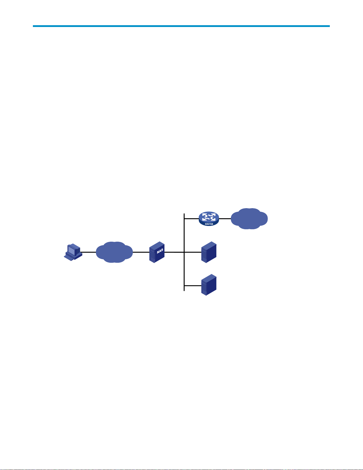
AAA usually uses a client/server model. The client runs on the network access server (NAS) and the
server maintains user information centrally. In an AAA network, a NAS is a server for users but a client
for the AAA servers, as shown in Figure 1.
Figure 1 Network diagram for AAA
When a user tries to log in to the NAS, use network resources, or access other networks, the NAS
authenticates the user. The NAS can transparently pass the user’s authentication, authorization, and
accounting information to the servers. The RADIUS and HWTACACS protocols define how a NAS and a
remote server exchange user information between them.
In the network shown in Figure 1, there is a RADIUS server and an HWTACACS server. You can choose
different servers for different security functions. For example, you can use the HWTACACS server for
authentication and authorization, and the RADIUS server for accounting.
You can choose the three security functions provided by AAA as required. For example, if your company
only wants employees to be authenticated before they access specific resources, you only need to
configure an authentication server. If network usage information is needed, you must also configure an
accounting server.
AAA can be implemented through multiple protocols. The device supports using RADIUS and
HWTACACS for AAA. RADIUS is often used in practice.
1
Page 12
RADIUS
RADIUS servers
Users Clients Dictionary
Remote Authentication Dial-In User Service (RADIUS) is a distributed information interaction protocol that
uses a client/server model. RADIUS can protect networks against unauthorized access and is often used
in network environments where both high security and remote user access are required.
RADIUS uses UDP as the transport protocol. It uses UDP port 1812 for authentication and UDP port 1813
for accounting.
RADIUS was originally designed for dial-in user access. With the addition of new access methods,
RADIUS has been extended to support additional access methods, for example, Ethernet and ADSL.
RADIUS provides access authentication and authorization services, and its accounting function collects
and records network resource usage information.
Client/server model
The RADIUS client runs on the NASs located throughout the network. It passes user information to
designated RADIUS servers and acts on the responses (for example, rejects or accepts user access
requests).
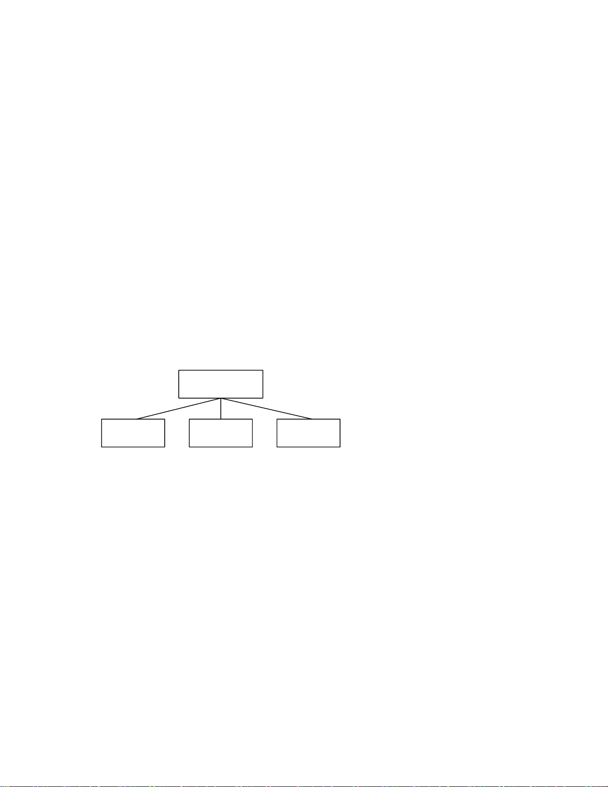
The RADIUS server runs on the computer or workstation at the network center and maintains information
related to user authentication and network service access. It listens to connection requests, authenticates
users, and returns user access control information (for example, rejecting or accepting the user access
request) to the clients.
In general, the RADIUS server maintains the following databases: Users, Clients, and Dictionary
Figure 2 RADIUS server components
Users—Stores user information, such as usernames, passwords, applied protocols, and IP addresses.
Clients—Stores information about RADIUS clients, such as shared keys and IP addresses.
Dictionary—Stores RADIUS protocol attributes and their values.
Security and authentication mechanisms
Information exchanged between a RADIUS client and the RADIUS server is authenticated with a shared
key, which is never transmitted over the network. This enhances information exchange security. In
addition, to prevent user passwords from being intercepted in non-secure networks, RADIUS encrypts
passwords before transmitting them.
A RADIUS server supports multiple user authentication methods, such as the Password Authentication
Protocol (PAP) and the Challenge Handshake Authentication Protocol (CHAP). Moreover, a RADIUS
server can act as the client of another AAA server to provide authentication proxy services.
RADIUS basic message exchange process
Figure 3 illustrates the interactions between the host, the RADIUS client, and the RADIUS server.
2
Page 13
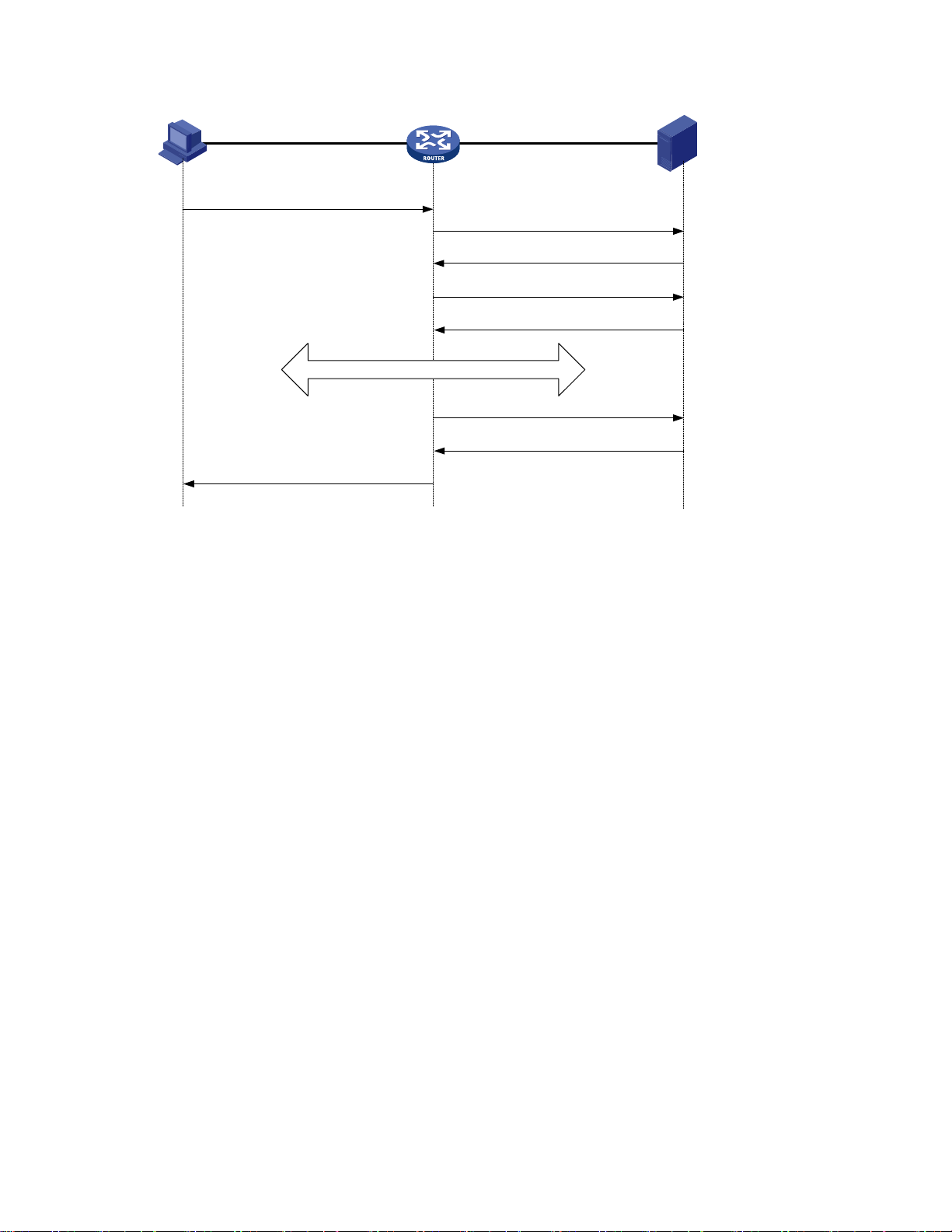
Figure 3 RADIUS basic message exchange process
RADIUS client
RADIUS server
1) Username and password
3) Access-Accept/Reject
2) Access-Request
4) Accounting-Request (start)
5) Accounting-Response
7) Accounting-Request (stop)
8) Accounting-Response
9) Notification of access termination
Host
6) The host accesses the resources
RADIUS operates in the following manner:
1. The host initiates a connection request carrying the username and password to the RADIUS client.
2. Having received the username and password, the RADIUS client sends an authentication request
(Access-Request) to the RADIUS server, with the user password encrypted by using the MessageDigest 5 (MD5) algorithm and the shared key.
3. The RADIUS server authenticates the username and password. If the authentication succeeds, it
sends back an Access-Accept message containing the user’s authorization information. If the
authentication fails, it returns an Access-Reject message.
4. The RADIUS client permits or denies the user according to the returned authentication result. If it
permits the user, it sends a start-accounting request (Accounting-Request) to the RADIUS server.
5. The RADIUS server returns a start-accounting response (Accounting-Response) and starts
accounting.
6. The user accesses the network resources.
7. The host requests the RADIUS client to tear down the connection and the RADIUS client sends a
stop-accounting request (Accounting-Request) to the RADIUS server.
8. The RADIUS server returns a stop-accounting response (Accounting-Response) and stops accounting
for the user.
9. The user stops access to network resources.
RADIUS packet format
RADIUS uses UDP to transmit messages. It ensures smooth message exchange between the RADIUS server
and the client through a series of mechanisms, including the timer management mechanism, the
retransmission mechanism, and the backup server mechanism. Figure 4 shows the RADIUS packet format.
3
Page 14
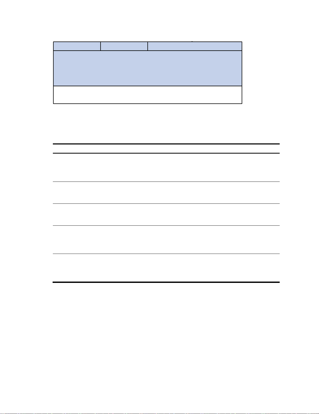
Figure 4 RADIUS packet format
Code
Attribute
Identifier
0
7
Length
Authenticator (16bytes)
7 15 31
Code
Packet type
Description
1
Access-Request
From the client to the server. A packet of this type carries user
information for the server to authenticate the user. It must
contain the User-Name attribute and can optionally contain the
attributes of NAS-IP-Address, User-Password, and NAS-Port.
2
Access-Accept
From the server to the client. If all the attribute values carried in
the Access-Request are acceptable, the authentication
succeeds, and the server sends an Access-Accept response.
3
Access-Reject
From the server to the client. If any attribute value carried in
the Access-Request is unacceptable, the authentication fails
and the server sends an Access-Reject response.
4
Accounting-Request
From the client to the server. A packet of this type carries user
information for the server to start or stop accounting for the
user. The Acct-Status-Type attribute in the packet indicates
whether to start or stop accounting.
5
Accounting-Response
From the server to the client. The server sends a packet of this
type to notify the client that it has received the AccountingRequest and has correctly recorded the accounting
information.
Descriptions of the fields are as follows:
1. The Code field (1 byte long) indicates the type of the RADIUS packet.
Table 1 Main values of the Code field
2. The Identifier field (1 byte long) is used to match request and response packets and to detect
retransmitted request packets. Request and response packets of the same type have the same
identifier.
3. The Length field (2 bytes long) indicates the length of the entire packet, including the Code,
Identifier, Length, Authenticator, and Attribute fields. Bytes beyond this length are considered
padding and are neglected upon reception. If the length of a received packet is less than this
length, the packet is dropped. The value of this field is in the range 20 to 4096.
4. The Authenticator field (16 bytes long) is used to authenticate replies from the RADIUS server and to
encrypt user passwords. There are two types of authenticators: request authenticator and response
authenticator.
4
Page 15

5. The Attribute field, with a variable length, carries the specific authentication, authorization, and
No.
Attribute
No.
Attribute
1
User-Name
45
Acct-Authentic
2
User-Password
46
Acct-Session-Time
3
CHAP-Password
47
Acct-Input-Packets
4
NAS-IP-Address
48
Acct-Output-Packets
5
NAS-Port
49
Acct-Terminate-Cause
6
Service-Type
50
Acct-Multi-Session-Id
7
Framed-Protocol
51
Acct-Link-Count
8
Framed-IP-Address
52
Acct-Input-Gigawords
9
Framed-IP-Netmask
53
Acct-Output-Gigawords
10
Framed-Routing
54
(unassigned)
11
Filter-ID
55
Event-Timestamp
12
Framed-MTU
56-59
(unassigned)
13
Framed-Compression
60
CHAP-Challenge
14
Login-IP-Host
61
NAS-Port-Type
15
Login-Service
62
Port-Limit
16
Login-TCP-Port
63
Login-LAT-Port
17
(unassigned)
64
Tunnel-Type
18
Reply-Message
65
Tunnel-Medium-Type
19
Callback-Number
66
Tunnel-Client-Endpoint
20
Callback-ID
67
Tunnel-Server-Endpoint
21
(unassigned)
68
Acct-Tunnel-Connection
22
Framed-Route
69
Tunnel-Password
23
Framed-IPX-Network
70
ARAP-Password
24
State
71
ARAP-Features
25
Class
72
ARAP-Zone-Access
26
Vendor-Specific
73
ARAP-Security
accounting information that defines the configuration details of the request or response. This field
contains multiple attributes, and each attribute is represented in triplets of Type, Length, and Value.
Type (1 byte long)—Indicates the type of the attribute. It is in the range 1 to 255. See Table 2 for
commonly used attributes for RADIUS authentication, authorization and accounting, which are
defined in RFC 2865, RFC 2866, RFC 2867, and RFC 2868. For more information about commonly
used standard RADIUS attributes, see ―Commonly used standard RADIUS attributes.―
Length (1 byte long)—Indicates the length of the attribute in bytes, including the Type, Length, and
Value fields.
Value (up to 253 bytes)—Value of the attribute. Its format and content depend on the Type and
Length fields.
Table 2 RADIUS attributes
5
Page 16

No.
Attribute
No.
Attribute
27
Session-Timeout
74
ARAP-Security-Data
28
Idle-Timeout
75
Password-Retry
29
Termination-Action
76
Prompt
30
Called-Station-Id
77
Connect-Info
31
Calling-Station-Id
78
Configuration-Token
32
NAS-Identifier
79
EAP-Message
33
Proxy-State
80
Message-Authenticator
34
Login-LAT-Service
81
Tunnel-Private-Group-id
35
Login-LAT-Node
82
Tunnel-Assignment-id
36
Login-LAT-Group
83
Tunnel-Preference
37
Framed-AppleTalk-Link
84
ARAP-Challenge-Response
38
Framed-AppleTalk-Network
85
Acct-Interim-Interval
39
Framed-AppleTalk-Zone
86
Acct-Tunnel-Packets-Lost
40
Acct-Status-Type
87
NAS-Port-Id
41
Acct-Delay-Time
88
Framed-Pool
42
Acct-Input-Octets
89
(unassigned)
43
Acct-Output-Octets
90
Tunnel-Client-Auth-id
44
Acct-Session-Id
91
Tunnel-Server-Auth-id
Extended RADIUS attributes
The RADIUS protocol features excellent extensibility. Attribute 26 (Vender-Specific) defined by RFC 2865
allows a vender to define extended attributes to implement functions that the standard RADIUS protocol
does not provide.
A vendor can encapsulate multiple type-length-value (TLV) sub-attributes in RADIUS packets for extension
in applications. As shown in Figure 5, a sub-attribute that can be encapsulated in Attribute 26 consists of
the following parts:
Vendor-ID (4 bytes long)—Indicates the ID of the vendor. Its most significant byte is 0; the other three
bytes contains a code that is compliant to RFC 1700. For more information about the proprietary
RADIUS sub-attributes of HP, see ―HP proprietary RADIUS sub-attributes.―
Vendor-Type—Indicates the type of the sub-attribute.
Vendor-Length—Indicates the length of the sub-attribute.
Vendor-Data—Indicates the contents of the sub-attribute.
6
Page 17

Figure 5 Segment of a RADIUS packet containing an extended attribute
Type Length
0
Vendor-ID
7 15 31
Vendor-ID (continued) Vendor-Type Vendor-Length
Vendor-Data
(Specified attribute value……)
23
……
HWTACACS
RADIUS
Uses TCP, providing more reliable network
transmission.
Uses UDP, providing higher transport efficiency.
Encrypts the entire packet except for the
HWTACACS header.
Encrypts only the user password field in an
authentication packet.
Protocol packets are complicated and authorization
is independent of authentication. Authentication and
authorization can be deployed on different
HWTACACS servers.
Protocol packets are simple and the authorization
process is combined with the authentication process.
Supports authorization of configuration commands.
Which commands a user can use depends on both
the user level and AAA authorization. A user can
use only commands that are not only of, or lower
than, the user level but also authorized by the
HWTACACS server.
Does not support authorization of configuration
commands. Which commands a user can use
depends on the level of the user and a user can use
all the commands of, or lower than, the user level.
HWTACACS
HW Terminal Access Controller Access Control System (HWTACACS) is an enhanced security protocol
based on TACACS (RFC 1492). Similar to RADIUS, it uses a client/server model for information exchange
between the NAS and the HWTACACS server.
HWTACACS mainly provides AAA services for Point-to-Point Protocol (PPP) users, Virtual Private Dial-up
Network (VPDN) users, and terminal users. In a typical HWTACACS application, some terminal users
need to log in to the NAS for operations. Working as the HWTACACS client, the NAS sends the
username and password of a user to the HWTACACS sever for authentication. After passing
authentication and being authorized, the user logs in to the device and performs operations, and the
HWTACACS server records the operations that the user performs.
Differences between HWTACACS and RADIUS
HWTACACS and RADIUS both provide authentication, authorization, and accounting services. They have
many features in common, like using a client/server model, using shared keys for user information
security, and providing flexibility and extensibility. Table 3 lists their differences.
Table 3 Primary differences between HWTACACS and RADIUS
HWTACACS basic message exchange process
The following takes a Telnet user as an example to describe how HWTACACS performs user
authentication, authorization, and accounting.
7
Page 18
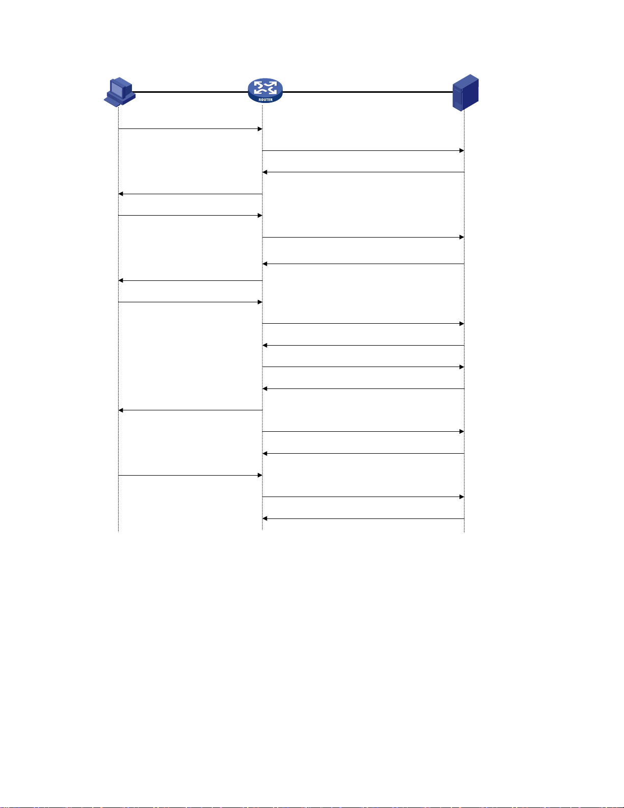
Figure 6 HWTACACS basic message exchange process for a Telnet user
Host HWTACACS client HWTACACS server
1) The user logs in
2) Start-authentication packet
3) Authentication response requesting the username
4) Request for username
5) The user inputs the username
6) Authentication continuance packet with the
username
7) Authentication response requesting the login
password
8) Request for password
9) The user inputs the password
11) Authentication response indicating successful
authentication
12) User authorization request packet
13) Authorization response indicating successful
authorization
14) The user logs in successfully
15) Start-accounting request
16) Accounting response indicating the start of
accounting
17) The user logs off
18) Stop-accounting request
19) Stop-accounting response
10) Authentication continuance packet with the
login password
Here is the process:
1. A Telnet user sends an access request to the HWTACACS client.
2. Upon receiving the request, the HWTACACS client sends a start-authentication packet to the
HWTACACS server.
3. The HWTACACS server sends back an authentication response to request the username.
4. Upon receiving the response, the HWTACACS client asks the user for the username.
5. The user inputs the username.
6. After receiving the username, the HWTACACS client sends the server a continue-authentication
packet that carries the username.
7. The HWTACACS server sends back an authentication response, requesting the login password.
8. Upon receipt of the response, the HWTACACS client asks the user for the login password.
8
Page 19
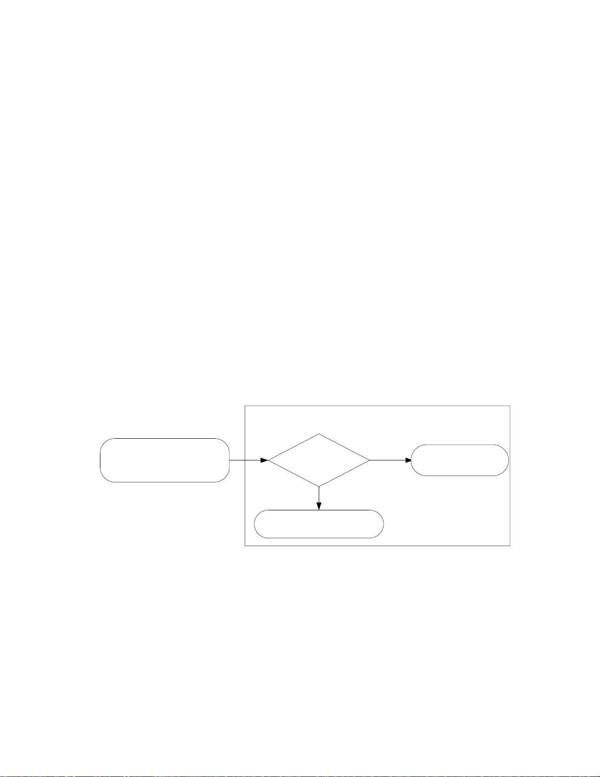
9. The user inputs the password.
Username carries
@domain-name?
A user enters the username in
the form of
userid@domain-name
or userid
Use domain domain-name
to authenticate the user
Use the default domain to
authenticate the user
Yes
No
NAS
10. After receiving the login password, the HWTACACS client sends the HWTACACS server a
continue-authentication packet that carries the login password.
11. The HWTACACS server sends back an authentication response to indicate that the user has passed
authentication.
12. The HWTACACS client sends the user authorization request packet to the HWTACACS server.
13. The HWTACACS server sends back the authorization response, indicating that the user is now
authorized.
14. Knowing that the user is now authorized, the HWTACACS client pushes its configuration interface
to the user.
15. The HWTACACS client sends a start-accounting request to the HWTACACS server.
16. The HWTACACS server sends back an accounting response, indicating that it has received the
start-accounting request.
17. The user logs off.
18. The HWTACACS client sends a stop-accounting request to the HWTACACS server.
19. The HWTACACS server sends back a stop-accounting response, indicating that the stop-accounting
request has been received.
Domain-based user management
A NAS manages users based on Internet service provider (ISP) domains. On a NAS, each user belongs
to one ISP domain. A NAS determines the ISP domain a user belongs to by the username entered by the
user at login, as shown in Figure 7.
Figure 7 Determine the ISP domain of a user by the username
The authentication, authorization, and accounting of a user depends on the AAA methods configured for
the domain that the user belongs to. If no specific AAA methods are configured for the domain, the
default methods are used. By default, a domain uses local authentication, local authorization, and local
accounting.
The AAA feature allows you to manage users based on their access types:
LAN users—Users on a LAN who must pass 802.1X authentication or MAC address authentication
Login users—Users who want to log in to the device, including SSH users, Telnet users, FTP users,
Portal users—Users who must pass portal authentication to access the network.
to access the network.
and terminal service users.
9
Page 20

For a user who has logged in to the device, AAA provides the following services to enhance device
NAS
RADIUS server
RADIUS serverNAS/
IP network
IP network
security:
Command authorization—Enables the NAS to defer to the authorization server to determine whether
a command entered by a login user is permitted for the user, ensuring that login users execute only
commands they are authorized to execute. For more information about command authorization, see
the Fundamentals Configuration Guide.
Command accounting—Allows the accounting server to record all commands executed on the
device or all authorized commands successfully executed. For more information about command
accounting, see the Fundamentals Configuration Guide.
Level switching authentication—Allows the authentication server to authenticate users performing
privilege level switching. As long as passing level switching authentication, users can switch their
user privilege levels, without logging out and disconnecting current connections. For more
information about user privilege level switching, see the Fundamentals Configuration Guide.
You can configure different authentication, authorization, and accounting methods for different users in a
domain. See ―Configuring AAA methods for ISP domains.―
RADIUS server feature of the device
Generally, the RADIUS server runs on a computer or workstation, and the RADIUS client runs on a NAS
device. A network device that supports the RADIUS server feature can also serve as the RADIUS server,
working with RADIUS clients to implement user authentication, authorization, and accounting. As shown
in Figure 8, the RADIUS server and client can reside on the same device or different devices.
Using a network device as the RADIUS server simplifies networking and reduces deployment costs. This
implementation is usually deployed on networks by using the clustering feature. In such a scenario,
configure the RADIUS server feature on a management device at the distribution layer, so that the device
functions as a RADIUS server to cooperate with cluster member switches at the access layer to provide
user authentication and authorization services.
Figure 8 Devices functioning as a RADIUS server
A network device serving as the RADIUS server can provide the following functions:
User information management—Supports creating, modifying, and deleting user information,
including the username, password, authority, lifetime, and user description.
RADIUS client information management—Supports creating, and deleting RADIUS clients, which are
identified by IP addresses and configured with attributes such as a shared key. After being
configured with a managed client range, the RADIUS server processes only the RADIUS packets
10
Page 21

from the clients within the management range. A shared key is used to ensure secure communication
NOTE:
The UDP port number for RADIUS authentication is 1812 in the standard RADIUS protocol, but is 1645
on HP devices. Specify 1645 as the authentication port number when you use an HP device as a
RADIUS client.
No.
Attribute
Description
1
User-Name
Name of the user to be authenticated.
2
User-Password
User password for PAP authentication, present only in Access-Request packets
in PAP authentication mode.
3
CHAP-Password
Digest of the user password for CHAP authentication, present only in AccessRequest packets in CHAP authentication mode.
4
NAS-IP-Address
IP address for the server to identify a client. Usually, a client is identified by the
IP address of the access interface on the NAS, namely the NAS IP address.
This attribute is present in only Access-Request packets.
5
NAS-Port
Physical port of the NAS that the user accesses.
6
Service-Type
Type of service that the user has requested or type of service to be provided.
7
Framed-Protocol
Encapsulation protocol.
8
Framed-IP-Address
IP address to be configured for the user.
11
Filter-ID
Name of the filter list.
between a RADIUS client and the RADIUS server.
RADIUS authentication and authorization. RADIUS accounting is not supported.
Upon receiving a RADIUS packet, a device working as the RADIUS server checks whether the sending
client is under its management. If yes, it verifies the packet validity by using the shared key, checks
whether there is an account with the username, whether the password is correct, and whether the user
attributes meet the requirements defined on the RADIUS server (for example, whether the account has
expired). Then, the RADIUS server assigns the corresponding authority to the client if the authentication
succeeds, or denies the client if the authentication fails.
Protocols and standards
The following protocols and standards are related to AAA, RADIUS, and HWTACACS:
RFC 2865, Remote Authentication Dial In User Service (RADIUS)
RFC 2866, RADIUS Accounting
RFC 2867, RADIUS Accounting Modifications for Tunnel Protocol Support
RFC 2868, RADIUS Attributes for Tunnel Protocol Support
RFC 2869, RADIUS Extensions
RFC 1492, An Access Control Protocol, Sometimes Called TACACS
RADIUS attributes
Commonly used standard RADIUS attributes
11
Page 22

No.
Attribute
Description
12
Framed-MTU
Maximum transmission unit (MTU) for the data link between the user and NAS.
For example, with 802.1X EAP authentication, NAS uses this attribute to notify
the server of the MTU for EAP packets, so as to avoid oversized EAP packets.
14
Login-IP-Host
IP address of the NAS interface that the user accesses.
15
Login-Service
Type of the service that the user uses for login.
18
Reply-Message
Text to be displayed to the user, which can be used by the server to indicate,
for example, the reason of the authentication failure.
26
Vendor-Specific
Vendor specific attribute. A packet can contain one or more such proprietary
attributes, each of which can contain one or more sub-attributes.
27
Session-Timeout
Maximum duration of service to be provided to the user before termination of
the session.
28
Idle-Timeout
Maximum idle time permitted for the user before termination of the session.
31
Calling-Station-Id
User identification that the NAS sends to the server. With the LAN access
service provided by an HP device, this attribute carries the MAC address of
the user in the format HHHH-HHHH-HHHH.
32
NAS-Identifier
Identification that the NAS uses for indicating itself.
40
Acct-Status-Type
Type of the Accounting-Request packet. Possible values are as follows:
1—Start
2—Stop
3—Interium-Update
4—Reset-Charge
7—Accounting-On (Defined in 3GPP, the 3rd Generation Partnership
Project)
8—Accounting-Off (Defined in 3GPP)
9 to 14 —Reserved for tunnel accounting
15 —Reserved for failed
45
Acct-Authentic
Authentication method used by the user. Possible values are as follows:
1—RADIUS
2—Local
3—Remote
60
CHAP-Challenge
CHAP challenge generated by the NAS for MD5 calculation during CHAP
authentication.
61
NAS-Port-Type
Type of the physical port of the NAS that is authenticating the user. Possible
values are as follows:
15 —Ethernet
16 —Any type of ADSL
17 —Cable (with cable for cable TV)
201—VLAN
202—ATM
If the port is an ATM or Ethernet one and VLANs are implemented on it, the
value of this attribute is 201.
79
EAP-Message
Used for encapsulating EAP packets to allow the NAS to authenticate dial-in
users via EAP without having to understand the EAP protocol.
12
Page 23

No.
Attribute
Description
80
MessageAuthenticator
Used for authentication and checking of authentication packets to prevent
spoofing Access-Requests. This attribute is used when RADIUS supports EAP
authentication.
87
NAS-Port-Id
String for describing the port of the NAS that is authenticating the user.
No.
Sub-attribute
Description
1
Input-Peak-Rate
Peak rate in the direction from the user to the NAS, in bps.
2
Input-Average-Rate
Average rate in the direction from the user to the NAS, in bps.
3
Input-Basic-Rate
Basic rate in the direction from the user to the NAS, in bps.
4
Output-Peak-Rate
Peak rate in the direction from the NAS to the user, in bps.
5
Output-Average-Rate
Average rate in the direction from the NAS to the user, in bps.
6
Output-Basic-Rate
Basic rate in the direction from the NAS to the user, in bps.
15
Remanent_Volume
Remaining, available total traffic of the connection, in different units for
different server types.
20
Command
Operation for the session, used for session control. Possible values are as
follows:
1—Trigger-Request
2—Terminate-Request
3—SetPolicy
4—Result
5—PortalClear
24
Control_Identifier
Identification for retransmitted packets. For retransmitted packets of the
same session, this attribute must take the same value; for retransmitted
packets of different sessions, this attribute may take the same value. The
client response of a retransmitted packet must also carry this attribute and
the value of the attribute must be the same.
For Accounting-Request packets of the start, stop, and interim update types,
the Control-Identifier attribute, if present, makes no sense.
25
Result_Code
Result of the Trigger-Request or SetPolicy operation. A value of zero means
the operation succeeded, any other value means the operation failed.
26
Connect_ID
Index of the user connection
28
Ftp_Directory
Working directory of the FTP user.
For an FTP user, when the RADIUS client acts as the FTP server, this
attribute is used to set the FTP directory on the RADIUS client.
29
Exec_Privilege
Priority of the EXEC user
59
NAS_Startup_Timestam
p
Startup time of the NAS in seconds, which is represented by the time
elapsed after 00:00:00 on Jan. 1, 1970 (UTC).
60
Ip_Host_Addr
IP address and MAC address of the user carried in authentication and
accounting requests, in the format A.B.C.D hh:hh:hh:hh:hh:hh. A space is
required between the IP address and the MAC address.
61
User_Notify
Information that needs to be sent from the server to the client transparently
HP proprietary RADIUS sub-attributes
13
Page 24

No.
Sub-attribute
Description
62
User_HeartBeat
Hash value assigned after an 802.1X user passes authentication, which is
a 32-byte string. This attribute is stored in the user list on the device and is
used for verifying the handshake messages from the 802.1X user. This
attribute exists in only Access-Accept and Accounting-Request packets.
140
User_Group
User groups assigned after the SSL VPN user passes authentication. A user
may belong to more than one user group. In this case, the user groups are
delimited by semi-colons. This attribute is used for cooperation with the SSL
VPN device.
141
Security_Level
Security level assigned after the SSL VPN user passes security
authentication
201
Input-Interval-Octets
Bytes input within a real-time accounting interval
202
Output-Interval-Octets
Bytes output within a real-time accounting interval
203
Input-Interval-Packets
Packets input within an accounting interval, in the unit set on the device
204
Output-Interval-Packets
Packets output within an accounting interval, in the unit set on the device
205
Input-IntervalGigawords
Result of bytes input within an accounting interval divided by 4G bytes
206
Output-IntervalGigawords
Result of bytes output within an accounting interval divided by 4G bytes
207
Backup-NAS-IP
Backup source IP address for sending RADIUS packets
255
Product_ID
Product name
AAA configuration considerations and task list
To configure AAA, you must complete these tasks on the NAS:
1. Configure the required AAA schemes.
Local authentication—Configure local users and the related attributes, including the usernames and
passwords of the users to be authenticated.
Remote authentication—Configure the required RADIUS and HWTACACS schemes, and configure
user attributes on the servers accordingly.
2. Configure AAA methods for the users’ ISP domains.
Authentication method—No authentication (none), local authentication (local), or remote
authentication (scheme)
Authorization method—No authorization (none), local authorization (local), or remote authorization
(scheme)
Accounting method—No accounting (none), local accounting (local), or remote accounting
(scheme)
14
Page 25
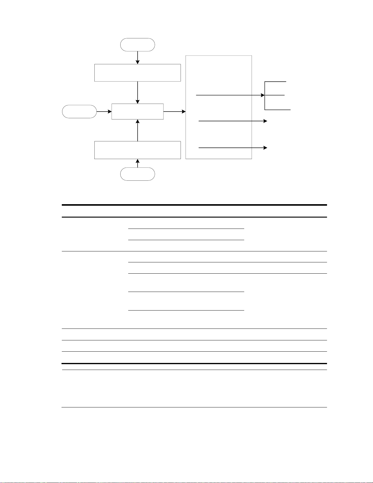
Figure 9 AAA configuration diagram
Configure the RADIUS, HWTACACS
schemes to be referenced
none/ local/ scheme
Authorization method
Accounting method
Configure AAA methods
Create an ISP domain
and enter its view
local (default method)
none
scheme
Authentication method
Configure local users and related
attributes
none/ local/ scheme
+
+
Local AAA
Remote AAA
No AAA
Task
Remarks
Configuring AAA
schemes
Configuring local users
Required
Complete at least one task.
Configuring RADIUS schemes
Configuring HWTACACS schemes
Configuring AAA
methods for ISP domains
Creating an ISP domain
Required
Configuring ISP domain attributes
Optional
Configuring AAA authentication methods for
an ISP domain
Required
Complete at least one task.
Configuring AAA authorization methods for
an ISP domain
Configuring AAA accounting methods for an
ISP domain
Tearing down user connections forcibly
Optional
Configuring a network device as a RADIUS server
Optional
Displaying and maintaining AAA
Optional
NOTE:
For login users, you must configure the login authentication mode for the user interfaces as scheme
before performing the above configurations. For more information, see the
Fundamentals Configuration
Guide
.
Table 4 AAA configuration task list
15
Page 26

Configuring AAA schemes
Configuring local users
For local authentication, you must create local users and configure user attributes on the device in
advance. The local users and attributes are stored in the local user database on the device. A local user
is uniquely identified by a username. Configurable local user attributes are as follows:
Service type
Types of services that the user can use. Local authentication checks the service types of a local user. If
none of the service types is available, the user cannot pass authentication.
Service types include FTP, LAN access, Portal, SSH, Telnet, and Terminal.
User state
Indicates whether or not a local user can request network services. There are two user states: active and
blocked. A user in the active state can request network services, but a user in the blocked state cannot.
Maximum number of users using the same local user account
Indicates how many users can use the same local user account for local authentication.
Expiration time
Indicates the expiration time of a local user account. A user must use a local user account that has not
expired to pass local authentication.
User group
Each local user belongs to a local user group and bears all attributes of the group, such as the password
control attributes and authorization attributes. For more information about local user group, see
―Configuring user group attributes.―
Password control attributes
Password control attributes help you improve the security of local users’ passwords. Password control
attributes include password aging time, minimum password length, and password composition policy.
You can configure a password control attribute in system view, user group view, or local user view,
making the attribute effective for all local users, all local users in a group, or only the local user. A
password control attribute with a smaller effective range has a higher priority. For more information about
password management and global password configuration, see the chapter ―Password control
configuration. ―
Binding attributes
Binding attributes are used to control the scope of users. Binding attributes are checked during
authentication. If the attributes of a user do not match the binding attributes configured for the user on the
access device, the user cannot pass authentication. Binding attributes include the ISDN calling number, IP
address, access port, MAC address, and native VLAN. For more information about binding attributes, see
―Configuring local user attributes.―
Authorization attributes
Authorization attributes indicate the rights that a user has after passing local authentication. Authorization
attributes include the ACL, PPP callback number, idle cut function, user level, user role, user profile, VLAN,
and FTP/SFTP work directory. For more information about authorization attributes, see ―Configuring local
user attributes.―
16
Page 27

You can configure an authorization attribute in user group view or local user view, making the attribute
Task
Remarks
Configuring local user attributes
Required
Configuring user group attributes
Optional
Displaying and maintaining local users and local user groups
Optional
To do…
Use the command…
Remarks
Enter system view
system-view
—
Set the password display mode for
all local users
local-user password-displaymode { auto | cipher-force }
Optional
auto by default, indicating to
display the password of a local
user in the way indicated by the
password command.
Add a local user and enter local user
view
local-user user-name
Required
No local user exists by default.
Configure a password for the local
user
password { cipher | simple }
password
Optional
Place the local user to the state of
active or blocked
state { active | block }
Optional
When created, a local user is in
the active state by default, and
the user can request network
services.
Set the maximum number of users
using the local user account
access-limit max-user-number
Optional
By default, there is no limit on
the maximum number of users
that use the same local user
account.
This limit is not effective for FTP
users.
Configure the
password control
attributes for the
local user
Set the
password aging
time
password-control aging aging-
time
Optional
By default, the setting for the
user group is used. If there is no
such setting for the user group,
the global setting is used.
Set the minimum
password length
password-control length length
Optional
By default, the setting for the
user group is used. If there is no
such setting for the user group,
the global setting is used.
effective for all local users in the group or only for the local user. The setting of an authorization attribute
in local user view takes precedence over that in user group view.
Local user configuration task list
Configuring local user attributes
Follow these steps to configure attributes for a local user:
17
Page 28

To do…
Use the command…
Remarks
Configure the
password
composition
policy
password-control composition
type-number type-number [
type-length type-length ]
Optional
By default, the setting for the
user group is used. If there is no
such setting for the user group,
the global setting is used.
Specify the service types for the local
user
service-type { ftp | lan-access |
{ ssh | telnet | terminal } * |
portal }
Required
By default, no service is
authorized to a local user.
Configure the binding attributes for
the local user
bind-attribute { call-number callnumber [ : subcall-number ] | ip
ip-address | location port slotnumber subslot-number portnumber | mac mac-address |
vlan vlan-id } *
Optional
By default, no binding attribute
is configured for a local user.
ip, location, mac, and vlan are
supported for LAN users. No
binding attribute is supported for
other types of local users.
Configure the authorization attributes
for the local user
authorization-attribute { acl acl-
number | callback-number
callback-number | idle-cut
minute | level level | user-
profile profile-name | user-role
security-audit | vlan vlan-id |
work-directory directory-name }
*
Optional
By default, no authorization
attribute is configured for a local
user.
For LAN and portal users, only
acl, idle-cut, user-profile, and
vlan are supported.
For SSH and terminal users, only
level is supported.
For FTP users, only level and
work-directory are supported.
For Telnet users, only level and
user-role is supported.
For other types of local users, no
binding attribute is supported.
Set the expiration time of the local
user
expiration-date time
Optional
Not set by default
When some users need to
access the network temporarily,
create a guest account and
specify an expiration time for the
account.
Assign the local user to a user group
group group-name
Optional
By default, a local user belongs
to the default user group system.
18
Page 29

NOTE:
For more information about password control attribute commands, see the chapter “Password control
configuration.”
On a device supporting the password control feature, local user passwords are not displayed, and the local-user
password-display-mode command is not effective.
With the local-user password-display-mode cipher-force command configured, a local user password is
always displayed in cipher text, regardless of the configuration of the password command. In this case, if you
use the save command to save the configuration, all existing local user passwords will still be displayed in cipher
text after the device restarts, even if you restore the display mode to auto.
The access-limit command configured for a local user takes effect only when local accounting is configured.
If the user interface authentication mode (set by the authentication-mode command in user interface view) is
AAA (scheme), which commands a login user can use after login depends on the privilege level authorized to
the user. If the user interface authentication mode is password (password) or no authentication (none), which
commands a login user can use after login depends on the level configured for the user interface (set by the user
privilege level command in user interface view). For an SSH user using public key authentication, which
commands are available depends on the level configured for the user interface. For more information about user
interface authentication mode and user interface command level, see the
Fundamentals Configuration Guide.
Be cautious when deciding which binding attributes should be configured for a local user. Binding attributes are
checked upon local authentication of a user. If the checking fails, the user fails the authentication.
Every configurable authorization attribute has its definite application environments and purposes. When
configuring authorization attributes for a local user, consider what attributes are needed.
To do…
Use the command…
Remarks
Enter system view
system-view
—
Create a user group and enter user
group view
user-group group-name
Required
Configure
password control
attributes for the
user group
Set the password
aging time
password-control aging aging-time
Optional
By default, the global
setting is used.
Set the minimum
password length
password-control length length
Optional
By default, the global
setting is used.
Configure the
password
composition policy
password-control composition typenumber type-number [ type-length
type-length ]
Optional
By default, the global
setting is used.
Configuring user group attributes
User groups simplify local user configuration and management. A user group consists of a group of local
users and has a set of local user attributes. You can configure local user attributes for a user group to
implement centralized user attributes management for the local users in the group. Configurable user
attributes include password control attributes and authorization attributes.
By default, every newly added local user belongs to the system default user group system and bears all
attributes of the group. To change the user group to which a local user belongs, use the user-group
command in local user view.
Follow these steps to configure attributes for a user group:
19
Page 30

To do…
Use the command…
Remarks
Configure the authorization attributes
for the user group
authorization-attribute { acl acl-
number | callback-number
callback-number | idle-cut minute |
level level | user-profile profile-name
| vlan vlan-id | work-directory
directory-name } *
Optional
By default, no
authorization attribute is
configured for a user
group.
To do…
Use the command…
Remarks
Display local user information
display local-user [ idle-cut { disable |
enable } | service-type { ftp | lanaccess | portal | ssh | telnet |
terminal } | state { active | block } |
user-name user-name | vlan vlan-id ]
[ slot slot-number ] [ | { begin |
exclude | include } regular-expression
]
Available in any view
Display the user group configuration
information
display user-group [ group-name ] [ |
{ begin | exclude | include } regular-
expression ]
Available in any view
Task
Remarks
Creating a RADIUS scheme
Required
Specifying the RADIUS authentication/authorization servers
Required
Specifying the RADIUS accounting servers and relevant
parameters
Optional
Setting the shared keys for RADIUS packets
Optional
Setting the maximum number of RADIUS request transmission
attempts
Optional
Setting the supported RADIUS server type
Optional
Setting the status of RADIUS servers
Optional
Setting the username format and traffic statistics units
Optional
Specifying a source IP address for outgoing RADIUS packets
Optional
Setting timers for controlling communication with RADIUS servers
Optional
Displaying and maintaining local users and local user groups
Configuring RADIUS schemes
A RADIUS scheme specifies the RADIUS servers that the device can cooperate with and defines a set of
parameters that the device uses to exchange information with the RADIUS servers. There may be
authentication/authorization servers and accounting servers, or primary servers and secondary servers.
The parameters mainly include the IP addresses of the servers, the shared keys, and the RADIUS server
type.
RADIUS scheme configuration task list
20
Page 31

Task
Remarks
Configuring RADIUS accounting-on
Optional
Specifying a security policy server
Optional
Configuring interpretation of RADIUS class attribute as CAR
parameters
Optional
Enabling the RADIUS trap function
Optional
Enabling the listening port of the RADIUS client
Optional
Displaying and maintaining RADIUS
Optional
To do…
Use the command…
Remarks
Enter system view
system-view
—
Create a RADIUS scheme and
enter RADIUS scheme view
radius scheme radius-scheme-
name
Required
No RADIUS scheme by default
NOTE:
A RADIUS scheme can be referenced by multiple ISP domains at the same time.
To do…
Use the command…
Remarks
Enter system view
system-view
—
Enter RADIUS scheme view
radius scheme radius-scheme-name
—
Specify the primary RADIUS
authentication/authorization
server
primary authentication { ip-address [ port-
number | key string] * | ipv6 ipv6-address [
port-number | key string ] * }
Required
Configure at least one
command.
No
authentication/authorizat
ion server is specified by
default.
Specify the secondary
RADIUS
authentication/authorization
server
secondary authentication { ip-address [ portnumber | key string] * | ipv6 ipv6-address [
port-number | key string ] * }
Creating a RADIUS scheme
Before performing other RADIUS configurations, follow these steps to create a RADIUS scheme and enter
RADIUS scheme view:
Specifying the RADIUS authentication/authorization servers
Follow these steps to specify the RADIUS authentication/authorization servers:
21
Page 32

NOTE:
If both the primary and secondary authentication/authorization servers are specified, the secondary one is used
when the primary one is not reachable.
If redundancy is not required, specify only the primary RADIUS authentication/authorization server.
In practice, you may specify one RADIUS server as the primary authentication/authorization server, and up to
16 RADIUS servers as the secondary authentication/authorization servers, or specify a server as the primary
authentication/authorization server for a scheme and as the secondary authentication/authorization servers for
another scheme at the same time.
The IP addresses of the primary and secondary authentication/authorization servers for a scheme must be
different from each other. Otherwise, the configuration will fail.
All servers for authentication/authorization and accountings, primary or secondary, must use IP addresses of the
same IP version.
To do…
Use the command…
Remarks
Enter system view
system-view
—
Enter RADIUS scheme view
radius scheme radius-scheme-name
—
Specify the primary RADIUS
accounting server
primary accounting { ip-address [ port-number
| key string ] * | ipv6 ipv6-address [ port-
number | key string ] * }
Required
Configure at least one
command.
No accounting server is
specified by default.
Specify the secondary RADIUS
accounting server
secondary accounting { ip-address [ portnumber | key string ] * | ipv6 ipv6-address [
port-number | key string ] * }
Enable the device to buffer
stop-accounting requests to
which no responses are
received
stop-accounting-buffer enable
Optional
Enabled by default
Set the maximum number of
stop-accounting attempts
retry stop-accounting retry-times
Optional
500 by default
Set the maximum number of
real-time accounting attempts
retry realtime-accounting retry-times
Optional
5 by default
Specifying the RADIUS accounting servers and relevant parameters
You can specify one primary accounting server and up to 16 secondary accounting servers for a RADIUS
scheme. When the primary server is not available, a secondary server is used, if any. When redundancy
is not required, specify only the primary server.
By setting the maximum number of real-time accounting attempts for a scheme, you make the device
disconnect users for whom no accounting response is received before the number of accounting attempts
reaches the limit.
When the device receives a connection teardown request from a host or a connection teardown
notification from an administrator, it sends a stop-accounting request to the accounting server. You can
enable buffering of non-responded stop-accounting requests to allow the device to buffer and resend a
stop-accounting request until it receives a response or the number of stop-accounting attempts reaches the
configured limit. In the latter case, the device discards the packet.
Follow these steps to specify the RADIUS accounting servers and perform related configurations:
22
Page 33

NOTE:
The IP addresses of the primary and secondary accounting servers must be different from each other. Otherwise,
the configuration fails.
All servers for authentication/authorization and accountings, primary or secondary, must use IP addresses of the
same IP version.
If you delete an accounting server serving users, the device can no longer send real-time accounting requests
and stop-accounting requests for the users to that server, or buffer the stop-accounting requests.
You can specify a RADIUS accounting server as the primary accounting server for one scheme and as the
secondary accounting server for another scheme at the same time.
RADIUS does not support accounting for FTP users.
To do…
Use the command…
Remarks
Enter system view
system-view
—
Enter RADIUS scheme view
radius scheme radius-scheme-
name
—
Set the shared key for RADIUS
authentication/authorization or
accounting packets
key { accounting | authentication
} string
Required
No shared key by default
NOTE:
A shared key configured on the device must be the same as that configured on the RADIUS server.
To do…
Use the command…
Remarks
Enter system view
system-view
—
Enter RADIUS scheme view
radius scheme radius-scheme-
name
—
Set the maximum number of
RADIUS request transmission
attempts
retry retry-times
Optional
3 by default
Setting the shared keys for RADIUS packets
The RADIUS client and RADIUS server use the MD5 algorithm to encrypt packets exchanged between
them and use shared keys to verify the packets. They must use the same shared key for the same type of
packets.
A shared key configured in this task is for all servers of the same type (accounting or authentication) in
the scheme, and has a lower priority than a shared key configured individually for a RADIUS server.
Follow these steps to set the shared keys for RADIUS packets:
Setting the maximum number of RADIUS request transmission attempts
Because RADIUS uses UDP packets to transfer data, the communication process is not reliable. RADIUS
uses a retransmission mechanism to improve reliability. If a NAS sends a RADIUS request to a RADIUS
server but receives no response before the response timeout timer expires, it retransmits the request. If the
number of transmission attempts exceeds the specified limit but it still receives no response, it tries to
communicate with other RADIUS servers in the active state. If no other servers are in the active state at the
time, it considers the authentication a failure. For more information about RADIUS server states, see
―Setting the status of RADIUS servers.―
Follow these steps to set the maximum number of RADIUS request transmission attempts:
23
Page 34

.
NOTE:
The maximum number of transmission attempts of RADIUS packets multiplied by the RADIUS server response
timeout period cannot be greater than 75 seconds.
For more information about the RADIUS server response timeout period, see “Setting timers for controlling
communication with RADIUS servers.“
To do…
Use the command…
Remarks
Enter system view
system-view
—
Enter RADIUS scheme view
radius scheme radius-scheme-
name
—
Set the RADIUS server type
server-type { extended |
standard }
Optional
standard by default
NOTE:
Changing the RADIUS server type will restore the unit for data flows and that for packets that are sent
to the RADIUS server to the defaults.
Setting the supported RADIUS server type
The supported RADIUS server type determines the type of the RADIUS protocol that the device uses to
communicate with the RADIUS server. It can be standard or extended:
Standard—Uses the standard RADIUS protocol, compliant to RFC 2865 and RFC 2866 or later.
Extended—Uses the proprietary RADIUS protocol of HP.
When the RADIUS server runs iMC, you must set the RADIUS server type to extended. When the RADIUS
server runs third-party RADIUS server software, either RADIUS server type applies. For the device to
function as a RADIUS server to authenticate login users, you must set the RADIUS server type to standard.
Follow these steps to set the RADIUS server type:
Setting the status of RADIUS servers
By setting the status of RADIUS servers to blocked or active, you can control which servers the device will
communicate with for authentication, authorization, and accounting or turn to when the current servers
are not available anymore. In practice, you can specify one primary RADIUS server and multiple
secondary RADIUS servers, with the secondary ones as the backup of the primary one. Generally, the
device chooses servers based on these rules:
When the primary server is in the active state, the device communicates with the primary server. If
the primary server fails, the device changes the state of the primary server to blocked and starts a
quiet timer for the server, and then turns to a secondary server in the active state (a secondary
server configured earlier has a higher priority). If the secondary server is unreachable, the device
changes the server’s status to blocked, starts a quiet timer for the server, and continues to check the
next secondary server in the active state. This search process continues until the device finds an
available secondary server or has checked all secondary servers in the active state. If the quiet timer
of a server expires or an authentication or accounting response is received from the server, the state
of the server changes back to active automatically, but the device does not check the server again. If
no server is found reachable during one search process, the device considers the authentication or
accounting attempt a failure.
Once the accounting process of a user starts, the device keeps sending the user’s real-time
accounting requests and stop-accounting requests to the same accounting server. If you remove the
24
Page 35

accounting server, real-time accounting requests and stop-accounting requests of the user cannot be
To do…
Use the command…
Remarks
Enter system view
system-view
—
Enter RADIUS scheme view
radius scheme radius-scheme-name
—
Set the status of the primary RADIUS
authentication/authorization server
state primary authentication {
active | block }
Optional
active for every server
specified in the RADIUS
scheme by default
Set the status of the primary RADIUS
accounting server
state primary accounting { active |
block }
Set the status of the secondary
RADIUS authentication/authorization
server
state secondary authentication [ ip
ipv4-address | ipv6 ipv6-address ]
{ active | block }
Set the status of the secondary
RADIUS accounting server
state secondary accounting [ ip
ipv4-address | ipv6 ipv6-address ]
{ active | block }
NOTE:
The server status set by the state command cannot be saved in the configuration file and will be restored to
active every time the server restarts.
To display the states of the servers, use the display radius scheme command.
delivered to the server anymore.
If you remove an authentication or accounting server in use, the communication of the device with
the server will soon time out, and the device will look for a server in the active state from scratch: it
checks the primary server (if any) first and then the secondary servers in the order they are
configured.
When the primary server and secondary servers are all in the blocked state, the device
communicates with the primary server. If the primary server is available, its state changes to active;
otherwise, its state remains to be blocked.
If one server is in the active state and the others are in the blocked state, the device only tries to
communicate with the server in the active state, even if the server is unavailable.
After receiving an authentication/accounting response from a server, the device changes the state of
the server identified by the source IP address of the response to active if the current state of the
server is blocked.
By default, the device sets the status of all RADIUS servers to active. In some cases, however, you may
need to change the status of a server. For example, if a server fails, you can change the status of the
server to blocked to avoid communication with the server.
Follow these steps to set the status of RADIUS servers:
Setting the username format and traffic statistics units
A username is usually in the format of userid@isp-name, where isp-name represents the name of the ISP
domain the user belongs to and is used by the device to determine which users belong to which ISP
domains. However, some earlier RADIUS servers cannot recognize usernames that contain an ISP domain
name. In this case, the device must remove the domain name of each username before sending the
username. You can set the username format on the device for this purpose.
The device periodically sends accounting updates to RADIUS accounting servers to report the traffic
statistics of online users. For normal and accurate traffic statistics, make sure that the unit for data flows
and that for packets on the device are consistent with those on the RADIUS server.
25
Page 36

Follow these steps to set the username format and the traffic statistics units for a RADIUS scheme:
To do…
Use the command…
Remarks
Enter system view
system-view
—
Enter RADIUS scheme view
radius scheme radius-scheme-
name
—
Set the format for usernames sent
to the RADIUS servers
user-name-format { keep-original
| with-domain | without-domain
}
Optional
By default, the ISP domain name
is included in the username.
Specify the unit for data flows or
packets sent to the RADIUS
servers
data-flow-format { data { byte |
giga-byte | kilo-byte | mega-byte
} | packet { giga-packet | kilopacket | mega-packet | onepacket } }*
Optional
byte for data flows and onepacket for data packets by
default.
NOTE:
If a RADIUS scheme defines that the username is sent without the ISP domain name, do not apply the RADIUS
scheme to more than one ISP domain. Otherwise, users using the same username but in different ISP domains
will be considered the same user.
For level switching authentication, the user-name-format keep-original and user-name-format without-domain
commands produce the same results: they ensure that usernames sent to the RADIUS server carry no ISP domain
name.
To do…
Use the command…
Remarks
Enter system view
system-view
—
Specify a source IP address
for outgoing RADIUS packets
radius nas-ip { ip-address |
ipv6 ipv6-address }
Required
By default, the IP address of the outbound
interface is used as the source IP address.
Specifying a source IP address for outgoing RADIUS packets
The source IP address of RADIUS packets that a NAS sends must match the IP address of the NAS
configured on the RADIUS server. A RADIUS server identifies a NAS by its IP address. Upon receiving a
RADIUS packet, a RADIUS server checks whether the source IP address of the packet is the IP address of
any managed NAS. If yes, the server processes the packet. If not, the server drops the packet.
Usually, the source address of outgoing RADIUS packets can be the IP address of the NAS’s any interface
that can communicate with the RADIUS server.
You can specify a source IP address for outgoing RADIUS packets in RADIUS scheme view for a specific
RADIUS scheme, or in system view for all RADIUS schemes. Before sending a RADIUS packet, a NAS
selects a source IP address in this order:
1. The source IP address specified for the RADIUS scheme.
2. The source IP address specified in system view.
3. The IP address of the outbound interface specified by the route.
Follow these steps to specify a source IP address for all RADIUS schemes:
Follow these steps to specify a source IP address for a specific RADIUS scheme:
26
Page 37

To do…
Use the command…
Remarks
Enter system view
system-view
—
Enter RADIUS scheme view
radius scheme radius-scheme-
name
—
Specify a source IP address
for outgoing RADIUS packets
nas-ip { ip-address | ipv6
ipv6-address }
Required
By default, the IP address of the outbound
interface is used as the source IP address.
To do…
Use the command…
Remarks
Enter system view
system-view
—
Enter RADIUS scheme view
radius scheme radius-scheme-
name
—
Set the RADIUS server response
timeout timer
timer response-timeout seconds
Optional
3 seconds by default
Set the quiet timer for the servers
timer quiet minutes
Optional
5 minutes by default
Set the real-time accounting timer
timer realtime-accounting minutes
Optional
12 minutes by default
Setting timers for controlling communication with RADIUS servers
The device uses the following types of timers to control the communication with a RADIUS server:
Server response timeout timer (response-timeout)—Defines the RADIUS request retransmission
interval. After sending a RADIUS request (authentication/authorization or accounting request), the
device starts this timer. If the device receives no response from the RADIUS server before this timer
expires, it resends the request.
Server quiet timer (quiet)—Defines the duration to keep an unreachable server in the blocked state.
If a server is not reachable, the device changes the server’s status to blocked, starts this timer for the
server, and tries to communicate with another server in the active state. After this timer expires, the
device changes the status of the server back to active.
Real-time accounting timer (realtime-accounting)—Defines the interval at which the device sends
real-time accounting packets to the RADIUS accounting server for online users. To implement realtime accounting, the device must periodically send real-time accounting packets to the accounting
server for online users.
Follow these steps to set timers for controlling communication with RADIUS servers:
27
Page 38

NOTE:
For an access module, the maximum number of transmission attempts multiplied by the RADIUS server response
timeout period must be less than the client connection timeout time and must not exceed 75 seconds. Otherwise,
stop-accounting messages cannot be buffered, and the primary/secondary server switchover cannot take place.
For example, because the client connection timeout time for voice access is 10 seconds, the product of the two
parameters must be less than 10 seconds; because the client connection timeout time for Telnet access is 30
seconds, the product of the two parameters must be less than 30 seconds.
When configuring the maximum number of RADIUS packet transmission attempts and the RADIUS server
response timeout period, be sure to take the number of secondary servers into account. If the retransmission
process takes too much time, the client connection in the access module may be timed out while the device is
trying to find an available server.
When a number of secondary servers are configured, the client connections of access modules that have a short
client connection timeout period may still be timed out during initial authentication or accounting, even if the
packet transmission attempt limit and server response timeout period are configured with small values. In this
case, the next authentication or accounting attempt may succeed because the device has set the state of the
unreachable servers to blocked and the time for finding a reachable server is shortened.
Be sure to set the server quiet timer properly. Too short a quiet timer may result in frequent authentication or
accounting failures because the device has to repeatedly attempt to communicate with a server that is in the
active state but is unreachable.
For more information about the maximum number of RADIUS packet retransmission attempts, see “Setting the
maximum number of RADIUS request transmission attempts.“
To do…
Use the command…
Remarks
Enter system view
system-view
—
Enter RADIUS scheme view
radius scheme radius-scheme-
name
—
Enable accounting-on and
configure parameters
accounting-on enable [
interval seconds | send send-
times ] *
Required
Disabled by default.
The default interval is 3 seconds and the
default number of send-times is 5.
NOTE:
The accounting-on feature requires the cooperation of the iMC network management system.
Configuring RADIUS accounting-on
The accounting-on feature enables a device to send accounting-on packets to the RADIUS server after it
reboots, making the server log out users who logged in through the device before the reboot. Without this
feature, users who were online before the reboot cannot re-log in after the reboot, because the RADIUS
server considers they are already online.
If a device sends an accounting-on packet to the RADIUS server but receives no response, it resends the
packet to the server at a particular interval for a specified number of times.
Follow these steps to configure the accounting-on feature for a RADIUS scheme:
Specifying a security policy server
The core of the EAD solution is integration and cooperation, and the security policy server is the
management and control center. As a collection of software, the security policy server provides functions
such as user management, security policy management, security status assessment, security cooperation
control, and security event audit.
28
Page 39

The NAS checks the validity of received control packets and accepts only control packets from known
To do…
Use the command…
Remarks
Enter system view
system-view
—
Enter RADIUS scheme view
radius scheme radius-scheme-name
—
Specify a security policy server
security-policy-server ip-address
Required
No security policy server is
specified by default
NOTE:
You can specify up to eight security policy servers for a RADIUS scheme.
To do…
Use the command…
Remarks
Enter system view
system-view
—
Enter RADIUS scheme view
radius scheme radius-
scheme-name
—
Specify to interpret the class
attribute as the CAR parameters
attribute 25 car
Required
Be default, RADIUS attribute 25 is not
interpreted as CAR parameters.
NOTE:
Whether to configure this feature depends on the implementation of the device and the RADIUS server.
servers. To use a security policy server that is independent of the AAA servers, you must configure the IP
address of the security policy server on the NAS. To implement all EAD functions, configure both the IP
address of the iMC security policy server and that of the iMC configuration platform on the NAS.
Follow these steps to specify a security policy server:
Configuring interpretation of RADIUS class attribute as CAR parameters
According to RFC 2865, a RADIUS server assigns the RADIUS class attribute (attribute 25) to a RADIUS
client. However, the RFC only requires the RADIUS client to send the attribute to the accounting server on
an ―as is‖ basis; it does not require the RADIUS client to interpret the attribute. Some RADIUS servers use
the class attribute to deliver the assigned committed access rate (CAR) parameters. In this case, the
access devices need to interpret the attribute to implement user-based traffic monitoring and controlling.
To support such applications, configure the access devices to interpret the class attribute as the CAR
parameters.
Follow these steps to configure the RADIUS client to interpret the class attribute as the CAR parameters:
Enabling the RADIUS trap function
With the RADIUS trap function, a NAS sends a trap message in either of these situations:
The status of a RADIUS server changes. If a NAS sends and retransmits an accounting or
authentication request to a RADIUS server but gets no response before the maximum number of
transmission attempts is reached, it considers the server unavailable and sends a trap message. If
the NAS receives a response from a RADIUS server in the blocked state, the NAS considers that the
RADIUS server is reachable again and also sends a trap message.
The ratio of the number of failed transmission attempts to the total number of authentication request
transmission attempts reaches the threshold. This threshold ranges from 1% to 100% and defaults to
30%. This threshold can only be configured through the MIB.
29
Page 40

The failure ratio is generally small. If you see a trap message triggered due to a higher failure ratio,
To do…
Use the command…
Remarks
Enter system view
system-view
—
Enable the RADIUS trap
function
radius trap { accounting-server-down |
authentication-error-threshold | authenticationserver-down }
Required
Disabled by default
To do…
Use the command…
Remarks
Enter system view
system-view
—
Enable the listening port of the
RADIUS client
radius client enable
Optional
Enabled by default
To do…
Use the command…
Remarks
Display the configuration information
of RADIUS schemes
display radius scheme [ radius-schemename ] [ slot slot-number ] [ | { begin
| exclude | include } regular-
expression ]
Available in any view
Display statistics about RADIUS
packets
display radius statistics [ slot slot-
number ] [ | { begin | exclude |
include } regular-expression ]
Available in any view
Display information about buffered
stop-accounting requests that get no
responses
display stop-accounting-buffer {
radius-scheme radius-server-name |
session-id session-id | time-range
start-time stop-time | user-name username } [ slot slot-number ] [ | { begin
| exclude | include } regular-
expression ]
Available in any view
Clear RADIUS statistics
reset radius statistics [ slot slot-number
]
Available in user view
Clear buffered stop-accounting
requests that get no responses
reset stop-accounting-buffer { radiusscheme radius-server-name | sessionid session-id | time-range start-time
stop-time | user-name user-name } [
slot slot-number ]
Available in user view
NOTE:
You cannot remove the HWTACACS schemes in use or change the IP addresses of the HWTACACS
servers in use.
check the configurations on the NAS and the RADIUS server and the communications between them.
Follow these steps to enable the RADIUS trap function:
Enabling the listening port of the RADIUS client
Follow these steps to enable the listening port of the RADIUS client:
Displaying and maintaining RADIUS
Configuring HWTACACS schemes
30
Page 41

Task
Remarks
Creating an HWTACACS scheme
Required
Specifying the HWTACACS authentication servers
Required
Specifying the HWTACACS authorization servers
Optional
Specifying the HWTACACS accounting servers
Optional
Setting the shared keys for HWTACACS packets
Required
Setting the username format and traffic statistics units
Optional
Specifying a source IP address for outgoing HWTACACS packets
Optional
Setting timers for controlling communication with HWTACACS servers
Optional
Displaying and maintaining HWTACACS
Optional
To do…
Use the command…
Remarks
Enter system view
system-view
—
Create an HWTACACS scheme
and enter HWTACACS scheme
view
hwtacacs scheme hwtacacs-
scheme-name
Required
Not defined by default
NOTE:
Up to 16 HWTACACS schemes can be configured.
A scheme can be deleted only when it is not referenced.
To do…
Use the command…
Remarks
Enter system view
system-view
—
Enter HWTACACS scheme
view
hwtacacs scheme hwtacacs-scheme-
name
—
Specify the primary
HWTACACS authentication
server
primary authentication ip-address [ port-
number ]
Required
Configure at least one
command.
No authentication server is
specified by default.
Specify the secondary
HWTACACS authentication
server
secondary authentication ip-address [
port-number ]
HWTACACS configuration task list
Creating an HWTACACS scheme
The HWTACACS protocol is configured on a per scheme basis. Before performing other HWTACACS
configurations, follow these steps to create an HWTACACS scheme and enter HWTACACS scheme view:
Specifying the HWTACACS authentication servers
Follow these steps to specify the HWTACACS authentication servers:
31
Page 42

NOTE:
If both the primary and secondary authentication servers are specified, the secondary one is used when the
primary one is not reachable.
If redundancy is not required, specify only the primary HWTACACS authentication server.
The IP addresses of the primary and secondary authentication servers cannot be the same. Otherwise, the
configuration fails.
You can remove an authentication server only when no active TCP connection for sending authentication packets
is using it.
To do…
Use the command…
Remarks
Enter system view
system-view
—
Enter HWTACACS scheme
view
hwtacacs scheme hwtacacs-scheme-
name
—
Specify the primary
HWTACACS authorization
server
primary authorization ip-address [ port-
number ]
Required
Configure at least one command.
No authorization server is
specified by default.
Specify the secondary
HWTACACS authorization
server
secondary authorization ip-address [
port-number ]
NOTE:
If both the primary and secondary authorization servers are specified, the secondary one is used when the
primary one is not reachable.
If redundancy is not required, specify only the primary HWTACACS authorization server.
The IP addresses of the primary and secondary authorization servers cannot be the same. Otherwise, the
configuration fails.
You can remove an authorization server only when no active TCP connection for sending authorization packets is
using it.
To do…
Use the command…
Remarks
Enter system view
system-view
—
Enter HWTACACS scheme
view
hwtacacs scheme hwtacacs-scheme-
name
—
Specify the primary
HWTACACS accounting server
primary accounting ip-address [
port-number ]
Required
Configure at least one command.
No accounting server is specified
by default.
Specify the secondary
HWTACACS accounting server
secondary accounting ip-address [
port-number ]
Specifying the HWTACACS authorization servers
Follow these steps to specify the HWTACACS authorization servers:
Specifying the HWTACACS accounting servers
Follow these steps to specify the HWTACACS accounting servers and perform related configurations:
32
Page 43

To do…
Use the command…
Remarks
Enable the device to buffer
stop-accounting requests
getting no responses
stop-accounting-buffer enable
Optional
Enabled by default
Set the maximum number of
stop-accounting request
transmission attempts
retry stop-accounting retry-times
Optional
100 by default
NOTE:
If both the primary and secondary accounting servers are specified, the secondary server is used when the
primary server is not reachable.
If redundancy is not required, specify only the primary HWTACACS accounting server.
The IP addresses of the primary and secondary accounting servers cannot be the same. Otherwise, the
configuration will fail.
You can remove an accounting server only when no active TCP connection for sending accounting packets is
using it.
HWTACACS does not support keeping accounts on FTP users.
To do…
Use the command…
Remarks
Enter system view
system-view
—
Enter HWTACACS scheme view
hwtacacs scheme hwtacacs-scheme-
name
—
Set the shared keys for
HWTACACS authentication,
authorization, and accounting
packets
key { accounting | authentication |
authorization } string
Required
No shared key by default
To do…
Use the command…
Remarks
Enter system view
system-view
—
Setting the shared keys for HWTACACS packets
The HWTACACS client and HWTACACS server use the MD5 algorithm to encrypt packets exchanged
between them and use shared keys to verify the packets. Only when they use the same key for an
exchanged packet can they receive the packets and make responses properly.
Follow these steps to set the shared keys for HWTACACS packets:
Setting the username format and traffic statistics units
A username is usually in the format of userid@isp-name, where isp-name represents the name of the ISP
domain the user belongs to and is used by the device to determine which users belong to which ISP
domains. However, some HWTACACS servers cannot recognize usernames that contain an ISP domain
name. In this case, the device must remove the domain name of each username before sending the
username. You can set the username format on the device for this purpose.
The device periodically sends accounting updates to HWTACACS accounting servers to report the traffic
statistics of online users. For normal and accurate traffic statistics, make sure that the unit for data flows
and that for packets on the device are consistent with those configured on the HWTACACS servers.
Follow these steps to set the username format and the traffic statistics units for an HWTACACS scheme:
33
Page 44

To do…
Use the command…
Remarks
Enter HWTACACS scheme view
hwtacacs scheme hwtacacs-scheme-
name
—
Set the format of usernames sent
to the HWTACACS servers
user-name-format { keep-original |
with-domain | without-domain }
Optional
By default, the ISP domain name
is included in the username.
Specify the unit for data flows or
packets sent to the HWTACACS
servers
data-flow-format { data { byte |
giga-byte | kilo-byte | mega-byte }
| packet { giga-packet | kilopacket | mega-packet | one-packet
} }*
Optional
byte for data flows and onepacket for data packets by
default.
NOTE:
If an HWTACACS server does not support a username with the domain name, configure the device to remove
the domain name before sending the username to the server.
For level switching authentication, the user-name-format keep-original and user-name-format without-domain
commands produce the same results: they ensure that usernames sent to the HWTACACS server carry no ISP
domain name.
To do…
Use the command…
Remarks
Enter system view
system-view
—
Specify a source IP address
for outgoing HWTACACS
packets
hwtacacs nas-ip ip-address
Required
By default, the IP address of the outbound
interface is used as the source IP address.
To do…
Use the command…
Remarks
Enter system view
system-view
—
Specifying a source IP address for outgoing HWTACACS packets
The source IP address of HWTACACS packets that a NAS sends must match the IP address of the NAS
configured on the HWTACACS server. An HWTACACS server identifies a NAS by IP address. Upon
receiving an HWTACACS packet, an HWTACACS server checks whether the source IP address of the
packet is the IP address of any managed NAS. If yes, the server processes the packet. If not, the server
drops the packet.
Usually, the source address of outgoing HWTACACS packets can be the IP address of the NAS’s any
interface that can communicate with the HWTACACS server.
You can specify the source IP address for outgoing HWTACACS packets in HWTACACS scheme view for
a specific HWTACACS scheme, or in system view for all HWTACACS schemes.
Before sending an HWTACACS packet, a NAS selects a source IP address in this order:
1. The source IP address specified for the HWTACACS scheme.
2. The source IP address specified in system view.
3. The IP address of the outbound interface specified by the route.
Follow these steps to specify a source IP address for all HWTACACS schemes:
Follow these steps to specify a source IP address for a specific HWTACACS scheme:
34
Page 45

To do…
Use the command…
Remarks
Enter HWTACACS scheme
view
hwtacacs scheme hwtacacs-
scheme-name
—
Specify a source IP address
for outgoing HWTACACS
packets
nas-ip ip-address
Required
By default, the IP address of the outbound
interface is used as the source IP address.
To do…
Use the command…
Remarks
Enter system view
system-view
—
Enter HWTACACS scheme view
hwtacacs scheme hwtacacs-
scheme-name
—
Set the HWTACACS server
response timeout timer
timer response-timeout seconds
Optional
5 seconds by default
Set the quiet timer for the primary
server
timer quiet minutes
Optional
5 minutes by default
Set the real-time accounting
interval
timer realtime-accounting minutes
Optional
12 minutes by default
NOTE:
For real-time accounting, a NAS must transmit the accounting information of online users to the HWTACACS
accounting server periodically. If the device does not receive any response to the information, it does not forcibly
disconnect the online users.
The real-time accounting interval must be a multiple of 3.
The setting of the real-time accounting interval somewhat depends on the performance of the NAS and the
HWTACACS server. A shorter interval requires higher performance.
To do…
Use the command…
Remarks
Display configuration information or
statistics of HWTACACS schemes
display hwtacacs [ hwtacacs-servername [ statistics ] ] [ slot slot-number ] [
| { begin | exclude | include } regular-
expression ]
Available in any view
Display information about buffered
stop-accounting requests that get no
responses
display stop-accounting-buffer
hwtacacs-scheme hwtacacs-scheme-
name [ slot slot-number ] [ | { begin |
exclude | include } regular-expression ]
Available in any view
Clear HWTACACS statistics
reset hwtacacs statistics { accounting |
all | authentication | authorization } [
slot slot-number ]
Available in user view
Setting timers for controlling communication with HWTACACS servers
Follow these steps to set timers regarding HWTACACS servers:
Displaying and maintaining HWTACACS
35
Page 46

Configuring AAA methods for ISP domains
To do…
Use the command…
Remarks
Enter system view
system-view
—
Create an ISP domain and enter
ISP domain view
domain isp-name
Required
Return to system view
quit
—
Specify the default ISP domain
domain default enable ispname
Optional
By default, the default ISP domain is the
factory default ISP domain system.
NOTE:
To delete the default ISP domain, you must change it to a non-default ISP domain (with the domain
default disable command) first.
To do…
Use the command…
Remarks
Enter system view
system-view
—
You configure AAA methods for an ISP domain by referencing configured AAA schemes in ISP domain
view. Each ISP domain has a set of default AAA methods, which are local authentication, local
authorization, and local accounting by default and can be customized. If you do not configure any AAA
methods for an ISP domain, the device uses the system default AAA methods for authentication,
authorization, and accounting of the users in the domain.
Configuration prerequisites
To use local authentication for users in an ISP domain, configure local user accounts (see ―Configuring
local user attributes―) on the access device.
To use remote authentication, authorization, and accounting, create the required RADIUS and
HWTACACS schemes as described in ―Configuring RADIUS schemes― and ―Configuring HWTACACS
schemes.―
Creating an ISP domain
In a networking scenario with multiple ISPs, an access device may connect users of different ISPs. Because
users of different ISPs may have different user attributes (for example, different username and password
structure, service type, and rights), you must configure ISP domains to distinguish the users and configure
different AAA methods for the ISP domains.
On a NAS, each user belongs to an ISP domain. A NAS can accommodate up to 16 ISP domains,
including the factory default ISP domain, which is named system. If a user does not provide the ISP
domain name at login, the system considers that the user belongs to the default ISP domain.
Follow these steps to create an ISP domain:
Configuring ISP domain attributes
Follow these steps to configure ISP domain attributes:
36
Page 47

To do…
Use the command…
Remarks
Enter ISP domain view
domain isp-name
—
Place the ISP domain to the state of
active or blocked
state { active | block }
Optional
By default, an ISP domain is in the
active state, and users in the domain
can request network services.
Specify the maximum number of
active users in the ISP domain
access-limit enable max-user-
number
Optional
No limit by default
Configure the idle cut function
idle-cut enable minute [ flow ]
Optional
Disabled by default
This command is effective for only
LAN users and portal users.
Configure the self-service server
location function
self-service-url enable url-string
Optional
Disabled by default
Specify the default authorization
user profile
authorization-attribute userprofile profile-name
Optional
By default, an ISP domain has no
default authorization user profile.
NOTE:
If a user passes authentication but is authorized with no user profile, the device authorizes the default user profile
of the ISP domain to the user and restricts the user’s behavior based on the profile. For more information about
the user profile, see the chapter “User profile configuration.”
A self-service RADIUS server, such as Intelligent Management Center (iMC), is required for the self-service server
location function to work. With the self-service function, a user can manage and control his or her accounting
information or card number. A server with self-service software is a self-service server.
Configuring AAA authentication methods for an ISP domain
In AAA, authentication, authorization, and accounting are separate processes. Authentication refers to the
interactive authentication process of username/password/user information during an access or service
request. The authentication process does not send authorization information to a supplicant or trigger
accounting.
AAA supports the following authentication methods:
No authentication (none)—All users are trusted and no authentication is performed. Generally, do
not use this method.
Local authentication (local)—Authentication is performed by the NAS, which is configured with the
user information, including the usernames, passwords, and attributes. Local authentication features
high speed and low cost, but the amount of information that can be stored is limited by the
hardware.
Remote authentication (scheme)—The access device cooperates with a RADIUS or HWTACACS
server to authenticate users. The device can use the standard RADIUS protocol or extended RADIUS
protocol in collaboration with systems like iMC to implement user authentication. Remote
authentication features centralized information management, high capacity, high reliability, and
support for centralized authentication service for multiple access devices. You can configure local or
37
Page 48

no authentication as the backup method to be used when the remote server is not available. No
To do…
Use the command…
Remarks
Enter system view
system-view
—
Enter ISP domain view
domain isp-name
—
Specify the default
authentication method for all
types of users
authentication default { hwtacacs-scheme
hwtacacs-scheme-name [ local ] | local |
none | radius-scheme radius-scheme-name [
local ] }
Optional
local by default
Specify the authentication
method for LAN users
authentication lan-access { local | none |
radius-scheme radius-scheme-name [ local |
none ] }
Optional
The default authentication
method is used by default.
Specify the authentication
method for login users
authentication login { hwtacacs-scheme
hwtacacs-scheme-name [ local ] | local |
none | radius-scheme radius-scheme-name [
local ] }
Optional
The default authentication
method is used by default.
Specify the authentication
method for portal users
authentication portal { local | none |
radius-scheme radius-scheme-name [ local ]
}
Optional
The default authentication
method is used by default.
Specify the authentication
method for privilege level
switching
authentication super { hwtacacs-scheme
hwtacacs-scheme-name | radius-scheme
radius-scheme-name }
Optional
The default authentication
method is used by default.
authentication can only be configured for LAN users as the backup method of remote authentication.
You can configure AAA authentication to work alone without authorization and accounting. By default,
an ISP domain uses the local authentication method.
Before configuring authentication methods, complete the following tasks:
For RADIUS or HWTACACS authentication, configure the RADIUS or HWTACACS scheme to be
referenced first. The local and none authentication methods do not require any scheme.
Determine the access mode or service type to be configured. With AAA, you can configure an
authentication method for each access mode and service type, limiting the authentication protocols
that can be used for access.
Determine whether to configure an authentication method for all access modes or service types.
Follow these steps to configure AAA authentication methods for an ISP domain:
38
Page 49

NOTE:
The authentication method specified with the authentication default command is for all types of users and has a
priority lower than that for a specific access mode.
With an authentication method that references a RADIUS scheme, AAA accepts only the authentication result
from the RADIUS server. The Access-Accept message from the RADIUS server does include the authorization
information, but the authentication process ignores the information.
With the radius-scheme
radius-scheme-name
local, or hwtacacs-scheme
hwtacacs-scheme-name
local keyword
and argument combination configured, local authentication is the backup method and is used only when the
remote server is not available.
If you specify only the local or none keyword in an authentication method configuration command, the device
has no backup authentication method and performs only local authentication or does not perform any
authentication.
If the method for level switching authentication references an HWTACACS scheme, the device uses the login
username of a user for level switching authentication of the user by default. If the method for level switching
authentication references a RADIUS scheme, the system uses the username configured for the corresponding
privilege level on the RADIUS server for level switching authentication, rather than the original username, the
login username or the username entered by the user. A username configured on the RADIUS server is in the
format of $enab
level
$, where
level
specifies the privilege level to which the user wants to switch. For example, if
user user1 of domain aaa wants to switch the privilege level to 3, the system uses $enab3@aaa$ for
authentication when the domain name is required and uses $enab3$ for authentication when the domain name
is not required.
Configuring AAA authorization methods for an ISP domain
In AAA, authorization is a separate process at the same level as authentication and accounting. Its
responsibility is to send authorization requests to the specified authorization servers and to send
authorization information to users after successful authorization. Authorization method configuration is
optional in AAA configuration.
AAA supports the following authorization methods:
No authorization (none)—The access device performs no authorization exchange. After passing
authentication, non-login users can access the network, FTP users can access the root directory of
the device, and other login users have only the rights of Level 0 (visiting).
Local authorization (local)—The access device performs authorization according to the user attributes
configured for users.
Remote authorization (scheme)—The access device cooperates with a RADIUS or an HWTACACS
server to authorize users. RADIUS authorization is bound with RADIUS authentication. RADIUS
authorization can work only after RADIUS authentication is successful, and the authorization
information is carried in the Access-Accept message. HWTACACS authorization is separate from
HWTACACS authentication, and the authorization information is carried in the authorization
response after successful authentication. You can configure local authorization or no authorization as
the backup method to be used when the remote server is not available.
Before configuring authorization methods, complete the following tasks:
1. For HWTACACS authorization, configure the HWTACACS scheme to be referenced first. For
RADIUS authorization, the RADIUS authorization scheme must be the same as the RADIUS
authentication scheme; otherwise, it does not take effect.
2. Determine the access mode or service type to be configured. With AAA, you can configure an
authorization scheme for each access mode and service type, limiting the authorization protocols
that can be used for access.
39
Page 50

3. Determine whether to configure an authorization method for all access modes or service types.
To do…
Use the command…
Remarks
Enter system view
system-view
—
Enter ISP domain view
domain isp-name
—
Specify the default
authorization method for all
types of users
authorization default { hwtacacs-scheme
hwtacacs-scheme-name [ local ] | local |
none | radius-scheme radius-scheme-name
[ local ] }
Optional
local by default
Specify the command
authorization method
authorization command { hwtacacs-scheme
hwtacacs-scheme-name [ local | none ] |
local | none }
Optional
The default authorization
method is used by default.
Specify the authorization
method for LAN users
authorization lan-access { local | none |
radius-scheme radius-scheme-name [ local
| none ] }
Optional
The default authorization
method is used by default.
Specify the authorization
method for login users
authorization login { hwtacacs-scheme
hwtacacs-scheme-name [ local ] | local |
none | radius-scheme radius-scheme-name
[ local ] }
Optional
The default authorization
method is used by default.
Specify the authorization
method for portal users
authorization portal { local | none |
radius-scheme radius-scheme-name [ local
] }
Optional
The default authorization
method is used by default.
NOTE:
The authorization method specified with the authorization default command is for all types of users and has a
priority lower than that for a specific access mode.
RADIUS authorization is special in that it takes effect only when the RADIUS authorization scheme is the same as
the RADIUS authentication scheme. In addition, if a RADIUS authorization fails, the error message returned to
the NAS says that the server is not responding.
With the radius-scheme
radius-scheme-name
local, or hwtacacs-scheme
hwtacacs-scheme-name
[ local |
none ] keyword and argument combination configured, local authorization or no authorization is the backup
method and is used only when the remote server is not available.
If you specify only the local or none keyword in an authorization method configuration command, the device
has no backup authorization method and performs only local authorization or does not perform any
authorization.
The authorization information from the RADIUS server is sent to the RADIUS client along with the authentication
response message. You cannot specify a separate RADIUS authorization server. If you use RADIUS for
authorization and authentication, you must use the same scheme setting for authorization and authentication;
otherwise, the system will display an error message.
Follow these steps to configure AAA authorization methods for an ISP domain:
Configuring AAA accounting methods for an ISP domain
In AAA, accounting is a separate process at the same level as authentication and authorization. Its
responsibility is to send accounting start/update/end requests to the specified accounting server.
Accounting is not required, and accounting method configuration is optional.
AAA supports the following accounting methods:
No accounting (none)—The system does not perform accounting for the users.
40
Page 51

Local accounting (local)—Local accounting is implemented on the access device. It is for counting
To do…
Use the command…
Remarks
Enter system view
system-view
—
Enter ISP domain view
domain isp-name
—
Enable the accounting optional
feature
accounting optional
Optional
Disabled by default
Specify the default accounting
method for all types of users
accounting default { hwtacacs-scheme
hwtacacs-scheme-name [ local ] |
local | none | radius-scheme radius-
scheme-name [ local ] }
Optional
local by default
Specify the command accounting
method
accounting command hwtacacsscheme hwtacacs-scheme-name
Optional
The default accounting method
is used by default.
Specify the accounting method for
LAN users
accounting lan-access { local | none |
radius-scheme radius-scheme-name [
local | none ] }
Optional
The default accounting method
is used by default.
Specify the accounting method for
login users
accounting login { hwtacacs-scheme
hwtacacs-scheme-name [ local ] |
local | none | radius-scheme radius-
scheme-name [ local ] }
Optional
The default accounting method
is used by default.
Specify the accounting method for
portal users
accounting portal { local | none |
radius-scheme radius-scheme-name [
local ] }
Optional
The default accounting method
is used by default.
and controlling the number of concurrent users who use the same local user account; it does not
provide statistics for charging. The maximum number of concurrent users using the same local user
account is set by the access-limit command in local user view.
Remote accounting (scheme)—The access device cooperates with a RADIUS server or HWTACACS
server for accounting of users. You can configure local or no accounting as the backup method to
be used when the remote server is not available.
By default, an ISP domain uses the local accounting method.
Before configuring accounting methods, complete the following tasks:
1. For RADIUS or HWTACACS accounting, configure the RADIUS or HWTACACS scheme to be
referenced first. The local and none authentication methods do not require any scheme.
2. Determine the access mode or service type to be configured. With AAA, you can configure an
accounting method for each access mode and service type, limiting the accounting protocols that
can be used for access.
3. Determine whether to configure an accounting method for all access modes or service types.
Follow these steps to configure AAA accounting methods for an ISP domain:
41
Page 52

NOTE:
With the accounting optional command configured, a user that would be otherwise disconnected can still use
the network resources even when no accounting server is available or communication with the current
accounting server fails.
The local accounting method is not used to implement accounting, but to work together with the access-limit
command, which is configured in local user view, to limit the number of local user connections. However, with
the accounting optional command configured, the limit on the number of local user connections is not effective.
The accounting method specified with the accounting default command is for all types of users and has a
priority lower than that for a specific access mode.
With the radius-scheme
radius-scheme-name
local or hwtacacs-scheme
hwtacacs-scheme-name
local keyword
and argument combination configured, local accounting is the backup method and is used only when the
remote server is not available.
If you specify only the local or none keyword in an accounting method configuration command, the device has
no backup accounting method and performs only local accounting or does not perform any accounting.
Accounting is not supported for FTP services.
To do…
Use the command…
Remarks
Enter system view
system-view
—
Tear down AAA user
connections forcibly
cut connection { access-type { dot1x | macauthentication | portal } | all | domain isp-name
| interface interface-type interface-number | ip
ip-address | mac mac-address | ucibindex ucibindex | user-name user-name | vlan vlan-id } [
slot slot-number ]
Required
Applicable to only
LAN access, and
portal user
connections.
Task
Remarks
Configuring a RADIUS user
Required
Specifying a RADIUS client
Required
Tearing down user connections forcibly
Follow these steps to tear down user connections forcibly:
Configuring a network device as a RADIUS server
RADIUS server functions configuration task list
Configuring a RADIUS user
This task is to create a RADIUS user and configure a set of attributes for the user on a network device that
serves as the RADIUS server. The user attributes include the password, authorization attribute, expiration
time, and user description. After completing this task, the specified RADIUS user can use the username
and password for RADIUS authentication on the device.
Follow these steps to configure a RADIUS user:
42
Page 53

To do…
Use the command…
Remarks
Enter system view
system-view
—
Create a RADIUS user and
enter RADIUS server user view
radius-server user user-name
Required
No RADIUS user exists by default.
Configure a password for the
RADIUS user
password [ cipher | simple ]
password
Optional
By default, no password is specified.
Configure the authorization
attribute for the RADIUS user
authorization-attribute { acl
acl-number | vlan vlan-id } *
Optional
Not configured by default.
Configure the expiration time
for the RADIUS user
expiration-date time
Optional
By default, no expiration time is
configured, and the system does not
check users’ expiration time.
Configure a description for the
RADIUS user
description text
Optional
Not configured by default.
NOTE:
You can use the authorization-attribute command to specify an authorization ACL and authorized
VLAN, which will be assigned by the RADIUS server to the RADIUS client (the NAS) after the RADIUS
user passes authentication. The NAS then uses the assigned ACL and VLAN to control user access. If
the assigned ACL does not exist on the NAS, ACL assignment will fail and the NAS will log the RADIUS
user out forcibly. If the assigned VLAN does not exist on the NAS, the NAS will create the VLAN and
add the RADIUS user or the access port to the VLAN.
To do…
Use the command…
Remarks
Enter system view
system-view
—
Specify a RADIUS client
radius-server client-ip ip-address [ key string ]
Required
No RADIUS client is
specified by default.
NOTE:
The IP address of a RADIUS client specified on the RADIUS server must be consistent with the source IP address
of RADIUS packets configured on the RADIUS client.
The shared key configured on the RADIUS server must be consistent with that configured on the RADIUS client.
Specifying a RADIUS client
This task is to specify the IP address of a client to be managed by the RADIUS server and configure the
shared key. The RADIUS server processes only the RADIUS packets sent from the specified clients.
Follow these steps to specify a RADIUS client
43
Page 54

Displaying and maintaining AAA
To do…
Use the command…
Remarks
Display the configuration
information of ISP domains
display domain [ isp-name ] [ | { begin |
exclude | include } regular-expression ]
Available in any view
Display information about user
connections
display connection [ access-type { dot1x |
mac-authentication | portal } | domain isp-
name | interface interface-type interfacenumber | ip ip-address | mac mac-address |
ucibindex ucib-index | user-name user-name |
vlan vlan-id ] [ slot slot-number ] [ | { begin |
exclude | include } regular-expression ]
Available in any view
Internet
Switch
Telnet user
Authentication/Accounting server
10.1.1.1/24
AAA configuration examples
AAA for Telnet users by an HWTACACS server
Network requirements
As shown in Figure 10, configure the switch to use the HWTACACS server to provide authentication,
authorization, and accounting services for Telnet users. Set the shared keys for authentication,
authorization, and accounting packets exchanged with the HWTACACS server to expert. Specify that the
switch remove the domain names in usernames before sending usernames to the HWTACACS server.
Figure 10 Configure AAA for Telnet users by an HWTACACS server
Configuration procedure
# Configure the IP addresses of the interfaces (omitted).
# Enable the Telnet server on the switch.
<Switch> system-view
[Switch] telnet server enable
# Configure the switch to use AAA for Telnet users.
[Switch] user-interface vty 0 4
[Switch-ui-vty0-4] authentication-mode scheme
[Switch-ui-vty0-4] quit
# Create HWTACACS scheme hwtac.
[Switch] hwtacacs scheme hwtac
44
Page 55

# Specify the primary authentication server.
NOTE:
Configuration of separate AAA for other types of users is similar to that given in this example. The only
difference is in the access type.
[Switch-hwtacacs-hwtac] primary authentication 10.1.1.1 49
# Specify the primary authorization server.
[Switch-hwtacacs-hwtac] primary authorization 10.1.1.1 49
# Specify the primary accounting server.
[Switch-hwtacacs-hwtac] primary accounting 10.1.1.1 49
# Set the shared key for authentication, authorization, and accounting packets to expert.
[Switch-hwtacacs-hwtac] key authentication expert
[Switch-hwtacacs-hwtac] key authorization expert
[Switch-hwtacacs-hwtac] key accounting expert
# Configure the scheme to remove the domain names in usernames before sending usernames to the
HWTACACS server.
[Switch-hwtacacs-hwtac] user-name-format without-domain
[Switch-hwtacacs-hwtac] quit
# Configure the AAA methods for the domain, or set default AAA methods for all types of users in the
domain.
[Switch] domain bbb
[Switch-isp-bbb] authentication login hwtacacs-scheme hwtac
[Switch-isp-bbb] authorization login hwtacacs-scheme hwtac
[Switch-isp-bbb] accounting login hwtacacs-scheme hwtac
[Switch-isp-bbb] quit
Or
[Switch] domain bbb
[Switch-isp-bbb] authentication default hwtacacs-scheme hwtac
[Switch-isp-bbb] authorization default hwtacacs-scheme hwtac
[Switch-isp-bbb] accounting default hwtacacs-scheme hwtac
When telnetting to the switch, a user enters username userid@bbb for authentication using domain bbb.
AAA for Telnet users by separate servers
Network requirements
As shown in Figure 11, configure the switch to provide local authentication, HWTACACS authorization,
and RADIUS accounting services for Telnet users. The username and the password for Telnet users are
both hello.
Set the shared keys for packets exchanged with the HWTACACS server and the RADIUS server to expert.
Configure the switch to remove the domain names in usernames before sending usernames to the servers.
45
Page 56

Figure 11 Configure AAA by separate servers for Telnet users
Internet
Switch
Telnet user
RADIUS
accounting server
10.1.1.1/24
HWTACACS
authorization server
10.1.1.2/24
Configuration procedure
# Configure the IP addresses of various interfaces (omitted).
# Enable the Telnet server on the switch.
<Switch> system-view
[Switch] telnet server enable
# Configure the switch to use AAA for Telnet users.
[Switch] user-interface vty 0 4
[Switch-ui-vty0-4] authentication-mode scheme
[Switch-ui-vty0-4] quit
# Configure the HWTACACS scheme.
[Switch] hwtacacs scheme hwtac
[Switch-hwtacacs-hwtac] primary authorization 10.1.1.2 49
[Switch-hwtacacs-hwtac] key authorization expert
[Switch-hwtacacs-hwtac] user-name-format without-domain
[Switch-hwtacacs-hwtac] quit
# Configure the RADIUS scheme.
[Switch] radius scheme rd
[Switch-radius-rd] primary accounting 10.1.1.1 1813
[Switch-radius-rd] key accounting expert
[Switch-radius-rd] server-type extended
[Switch-radius-rd] user-name-format without-domain
[Switch-radius-rd] quit
# Create a local user named hello.
[Switch] local-user hello
[Switch-luser-hello] service-type telnet
[Switch-luser-hello] password simple hello
[Switch-luser-hello] quit
# Configure the AAA methods for the ISP domain, or set default AAA methods for all types of users in the
domain.
[Switch] domain bbb
[Switch-isp-bbb] authentication login local
[Switch-isp-bbb] authorization login hwtacacs-scheme hwtac
[Switch-isp-bbb] accounting login radius-scheme rd
[Switch-isp-bbb] quit
46
Page 57

Or
NOTE:
The configuration of authentication and authorization for SSH users is similar to that for Telnet users.
The following takes SSH users as an example.
Internet
Switch
SSH user
RADIUS server
10.1.1.1/24
Vlan-int2
192.168.1.70/24
Vlan-int3
10.1.1.2/24
NOTE:
This example assumes that the RADIUS server runs iMC PLAT 5.0 (E0101) and iMC UAM 5.0 (E0101).
[Switch] domain bbb
[Switch-isp-bbb] authentication default local
[Switch-isp-bbb] authorization default hwtacacs-scheme hwtac
[Switch-isp-bbb] accounting default radius-scheme rd
When telnetting to the switch, a user enters username telnet@bbb for authentication using domain bbb.
Authentication/Authorization for SSH/Telnet users by a RADIUS server
Network requirements
As shown in Figure 12, configure an iMC server to act as the RADIUS server to provide authentication
and authorization services for SSH users.
Set both the shared keys for packets exchanged with the RADIUS server to expert, and configure the
switch to include the domain names in usernames to be sent to the RADIUS server.
Add an account on the RADIUS server, with the username hello@bbb. The SSH user uses the username
and the configured password to log in to the switch and is authorized with the privilege level of 3 after
login.
Figure 12 Configure authentication/authorization for SSH users by a RADIUS server
Configuration procedure
1. Configure the RADIUS server (iMC PLAT 5.0)
# Add an access device.
47
Log in to the iMC management platform, select the Service tab, and select User Access Manager > Access
Device from the navigation tree to enter the Access Device page. Then, click Add to enter the Add Access
Device window and perform the following configurations as shown in Figure 13.
Set the shared key for authentication and accounting to expert
Page 58

Specify the ports for authentication and accounting as 1812 and 1813 respectively
NOTE:
The IP address of the access device specified above must be the same as the source IP address of the
RADIUS packets sent from the device, which is the IP address of the outbound interface by default, or
otherwise the IP address specified with the nas-ip or radius nas-ip command on the device.
Select Device Management Service as the service type
Select HP(A-Series) as the access device type
Select the access device from the device list or manually add the device with the IP address of
10.1.1.2
Click OK to finish the operation
Figure 13 Add an access device
# Add a user for device management
Log in to the iMC management platform, select the User tab, and select Device Management User from
the navigation tree to enter the Device Management User page. Then, click Add to enter the Add Device
Management User window and perform the following configurations as shown in Figure 14.
Add a user named hello@bbb and specify the password
Select SSH as the service type
Set the EXEC privilege level to 3. This value identifies the privilege level of the SSH user after login
and defaults to 0.
Specify the IP address range of the hosts to be managed as 10.1.1.0 to 10.1.1.255
Click OK to finish the operation
48
Page 59

Figure 14 Add an account for device management
2. Configure the switch
# Configure the IP address of VLAN interface 2, through which the SSH user accesses the switch.
<Switch> system-view
[Switch] interface vlan-interface 2
[Switch-Vlan-interface2] ip address 192.168.1.70 255.255.255.0
[Switch-Vlan-interface2] quit
# Configure the IP address of VLAN-interface 3, through which the switch access the server.
[Switch] interface vlan-interface 3
[Switch-Vlan-interface3] ip address 10.1.1.2 255.255.255.0
[Switch-Vlan-interface3] quit
# Generate RSA and DSA key pairs and enable the SSH server.
[Switch] public-key local create rsa
[Switch] public-key local create dsa
[Switch] ssh server enable
# Configure the switch to use AAA for SSH users.
[Switch] user-interface vty 0 4
[Switch-ui-vty0-4] authentication-mode scheme
# Configure the user interfaces to support SSH.
[Switch-ui-vty0-4] protocol inbound ssh
[Switch-ui-vty0-4] quit
# Create RADIUS scheme rad.
49
Page 60

[Switch] radius scheme rad
# Specify the primary authentication server.
[Switch-radius-rad] primary authentication 10.1.1.1 1812
# Set the shared key for authentication packets to expert.
[Switch-radius-rad] key authentication expert
# Configure the scheme to include the domain names in usernames to be sent to the RADIUS server.
[Switch-radius-rad] user-name-format with-domain
# Specify the service type for the RADIUS server, which must be extended when the RADIUS server runs
iMC.
[Switch-radius-rad] server-type extended
[Switch-radius-rad] quit
# Configure the AAA methods for the domain.
[Switch] domain bbb
[Switch-isp-bbb] authentication login radius-scheme rad
[Switch-isp-bbb] authorization login radius-scheme rad
[Switch-isp-bbb] quit
3. Verify the configuration
After you complete the configuration, the SSH user should be able to use the configured account to
access the user interface of the switch and can access the demands of level 0 through level 3. .
# Use the display connection command to view the connection information on the switch.
[Switch] display connection
Index=1 ,Username=hello@bbb
IP=192.168.1.58
IPv6=N/A
Total 1 connection(s) matched.
AAA for 802.1X users by a RADIUS server
Network requirements
As shown in Figure 15, configure the switch to use the RADIUS server to perform authentication,
authorization, and accounting for 802.1X users. Set the shared keys for authentication and authorization
packets exchanged between the switch and the RADIUS server to expert and set the ports for
authentication/authorization and accounting to 1812 and 1813 respectively. Configure the switch to
include the domain names in usernames to be sent to the RADIUS server.
Configure MAC-based access control on GigabitEthernet 1/0/1 to authenticate all 802.1X users on the
port separately.
Configure an account for the user, with the username dot1x@bbb. Configure the authentication server to
assign the host to VLAN 4 after the host passes authentication. Register a monthly service that charges
120 dollars for up to 120 hours per month for the user.
50
Page 61

Figure 15 Configure AAA for 802.1X users by a RADIUS server
Internet
Switch
802.1X user
RADIUS server
Vlan-int2
10.1.1.1/24
Vlan-int3
10.1.1.2/24
Vlan-int4
GE1/0/1
NOTE:
Configure the interfaces and VLANs as shown in Figure 15. Make sure that the host can get a new IP address
manually or automatically and can access resources in the authorized VLAN after passing authentication.
NOTE:
This example assumes that the RADIUS server runs iMC PLAT 5.0 (E0101), iMC UAM 5.0 (E0101), and
iMC CAMS 5.0 (E0101).
NOTE:
The IP address of the access device specified above must be the same as the source IP address of the
RADIUS packets sent from the device, which is the IP address of the outbound interface by default, or
otherwise the IP address specified with the nas-ip or radius nas-ip command on the access device.
Configuration procedure
1. Configure the RADIUS server (iMC PLAT 5.0)
# Add an access device.
Log in to the iMC management platform, select the Service tab, and select User Access Manager > Access
Device from the navigation tree to enter the Access Device List page. Then, click Add to enter the Add
Access Device page and perform the following configurations:
Set the shared key for authentication and accounting to expert
Specify the ports for authentication and accounting as 1812 and 1813 respectively
Select LAN Access Service as the service type
Select HP(A-Series) as the access device type
Select the access device from the device list or manually add the device whose IP address is 10.1.1.2
Adopt the default settings for other parameters and click OK to finish the operation.
51
Page 62

Figure 16 Add an access device
# Add a charging policy.
Select the Service tab, and select Accounting Manager > Charging Plans from the navigation tree to enter
the charging policy configuration page. Then, click Add to enter the Add Charging Plan page and
perform the following configurations:
Add a plan named UserAcct
Select Flat rate as the charging template
In the Basic Plan Settings field, configure to charge the fixed fee of 120 dollars per month
In the Service Usage Limit field, set the Usage Threshold to 120 hours, allowing the user to access
the Internet for up to 120 hours per month
Adopt the default settings for other parameters and click OK to finish the operation.
Figure 17 Add a charging policy
# Add a service.
52
Page 63

Select the Service tab, and select User Access Manager > Service Configuration from the navigation tree
to enter the Service Configuration page. Then, click Add to enter the Add Service Configuration page and
perform the following configurations:
Add a service named Dot1x auth and set the Service Suffix to bbb, which indicates the
authentication domain for the 802.1X user. With the service suffix configured, you must configure
usernames to be sent to the RADIUS service to carry the domain name.
Specify UserAcct as the Charging Plan.
Select Deploy VLAN and set the ID of the VLAN to be assigned to 4.
Configure other parameters according to the actual situation.
Click OK to finish the operation.
Figure 18 Add a service
# Add a user.
Select the User tab, and select All Access Users from the navigation tree to enter the All Access Users
page. Then, click Add to enter the Add Access User page and perform the following configurations:
Select the user or add a user named test
Specify the account name as dot1x and configure the password
Select the access service Dot1x auth
Configure other parameters accordingly and click OK to finish the operation
53
Page 64

Figure 19 Add an access user account
2. Configure the switch
Configure a RADIUS scheme
# Create a RADIUS scheme named rad and enter its view.
<Switch> system-view
[Switch] radius scheme rad
# Set the server type for the RADIUS scheme. When using the iMC server, set the server type to
extended.
[Switch-radius-rad] server-type extended
# Specify the primary authentication server and primary accounting server, and configure the keys for
communication with the servers.
[Switch-radius-rad] primary authentication 10.1.1.1
[Switch-radius-rad] primary accounting 10.1.1.1
[Switch-radius-rad] key authentication expert
[Switch-radius-rad] key accounting expert
# Configure the scheme to include the domain names in usernames to be sent to the RADIUS server.
[Switch-radius-rad] user-name-format with-domain
[Switch-radius-rad] quit
Configure an authentication domain
# Create an ISP domain named bbb and enter its view.
[Switch] domain bbb
# Configure the ISP domain to use RADIUS scheme rad.
[Switch-isp-bbb] authentication lan-access radius-scheme rad
[Switch-isp-bbb] authorization lan-access radius-scheme rad
[Switch-isp-bbb] accounting lan-access radius-scheme rad
[Switch-isp-bbb] quit
54
Page 65

# Configure bbb as the default ISP domain for all users. Then, if a user enters a username without any ISP
NOTE:
If the 802.1X client of Windows XP is used, the properties of the 802.1X connection should be specifically
configured in the Authentication tab on the Properties page, where you must select the Enable IEEE 802.1X
authentication for this network option and specify the EAP type as MD5-Challenge.
If the iNode client is used, no advanced authentication options need to be enabled.
domain at login, the authentication and accounting methods of the default domain will be used for the
user.
[Switch] domain default enable bbb
Configure 802.1X authentication
# Enable 802.1X globally.
[Switch] dot1x
# Enable 802.1X for port GigabitEthernet 1/0/1.
[Switch] interface gigabitethernet 1/0/1
[Switch-GigabitEthernet1/0/1] dot1x
[Switch-GigabitEthernet1/0/1] quit
# Configure the access control method. (Optional. The default setting meets the requirement.)
[Switch] dot1x port-method macbased interface gigabitethernet 1/0/1
3. Verification
When using the iNode client, the user can pass authentication after entering username dot1x@bbb and
the correct password in the client property page. When using the Windows XP 802.1X client, the user
can pass authentication after entering the correct username and password in the pop-up authentication
page. After the user passes authentication, the server assigns the port connecting the client to VLAN 4.
Use the display connect command to view the connection information on the switch.
[Switch] display connection
Slot: 1
Index=22 , Username=dot1x@bbb
IP=192.168.1.58
IPv6=N/A
MAC=0015-e9a6-7cfe
Total 1 connection(s) matched on slot 1.
Total 1 connection(s) matched.
# View the information of the specified connection on the switch.
[Switch] display connection ucibindex 22
Slot: 1
Index=22 , Username=dot1x@bbb
MAC=0015-e9a6-7cfe
IP=192.168.1.58
IPv6=N/A
Access=8021X ,AuthMethod=CHAP
Port Type=Ethernet,Port Name=GigabitEthernet1/0/1
Initial VLAN=2, Authorized VLAN=4
ACL Group=Disable
User Profile=N/A
CAR=Disable
55
Page 66

Priority=Disable
Internet
Switch
Telnet user
192.168.1.58/24
HWTACACS server
10.1.1.1/24
Vlan-int2
192.168.1.70/24
Vlan-int3
10.1.1.2/24
Start=2011-04-26 19:41:12 ,Current=2011-04-26 19:41:25 ,Online=00h00m14s
Total 1 connection matched.
As the Authorized VLAN field in the output shows, VLAN 4 has been assigned to the user.
Level switching authentication for Telnet users by an HWTACACS server
Network requirements
As shown in Figure 20, configure the switch to use local authentication for the Telnet user and assign the
privilege level of 0 to the user after the user passes authentication.
Configure the switch to use the HWTACACS server for level switching authentication of the Telnet user,
and to use local authentication as the backup method.
Figure 20 Configure level switching authentication for Telnet users by an HWTACACS server
Configuration considerations
1. Configure the switch to use AAA, particularly, local authentication for Telnet users.
Create ISP domain bbb and configure it to use local authentication for Telnet users.
Create a local user account, configure the password, and assign the privilege level for the user to
enjoy after login.
2. On the switch, configure the authentication method for user privilege level switching.
Specify to use HWTACACS authentication and, if HWTACACS authentication is not available, use
local authentication for user level switching authentication.
Configure HWTACACS scheme hwtac and assign an IP address to the HWTACACS server. Set the
shared keys for message exchange and specify that usernames sent to the HWTACACS server carry
no domain name. Configure the domain to use the HWTACACS scheme hwtac for user privilege
level switching authentication.
Configure the password for local privilege level switching authentication.
3. On the HWTACACS server, add the username and password for user privilege level switching
Configuration procedure
authentication.
1. Configure the switch
# Configure the IP address of VLAN-interface 2, through which the Telnet user accesses the switch.
56
Page 67

<Switch> system-view
[Switch] interface vlan-interface 2
[Switch-Vlan-interface2] ip address 192.168.1.70 255.255.255.0
[Switch-Vlan-interface2] quit
# Configure the IP address of VLAN-interface 3, through which the switch communicates with the server.
[Switch] interface vlan-interface 3
[Switch-Vlan-interface3] ip address 10.1.1.2 255.255.255.0
[Switch-Vlan-interface3] quit
# Enable the switch to provide Telnet service.
[Switch] telnet server enable
# Configure the switch to use AAA for Telnet users.
[Switch] user-interface vty 0 4
[Switch-ui-vty0-4] authentication-mode scheme
[Switch-ui-vty0-4] quit
# Use HWTACACS authentication for user level switching authentication and, if HWTACACS
authentication is not available, use local authentication.
[Switch] super authentication-mode scheme local
# Create an HWTACACS scheme named hwtac.
[Switch] hwtacacs scheme hwtac
# Specify the IP address for the primary authentication server as 10.1.1.1 and the port for authentication
as 49.
[Switch-hwtacacs-hwtac] primary authentication 10.1.1.1 49
# Set the shared key for authentication packets to expert.
[Switch-hwtacacs-hwtac] key authentication expert
# Configure the scheme to remove the domain names in usernames before sending usernames to the
HWTACACS server.
[Switch-hwtacacs-hwtac] user-name-format without-domain
[Switch-hwtacacs-hwtac] quit
# Create ISP domain bbb.
[Switch] domain bbb
# Configure the ISP domain to use local authentication for Telnet users.
[Switch-isp-bbb] authentication login local
# Configure to use HWTACACS scheme hwtac for privilege level switching authentication.
[Switch-isp-bbb] authentication super hwtacacs-scheme hwtac
[Switch-isp-bbb] quit
# Create a local Telnet user named test.
[Switch] local-user test
[Switch-luser-test] service-type telnet
[Switch-luser-test] password simple aabbcc
# Configure the user level of the Telnet user to 0 after user login.
[Switch-luser-test] authorization-attribute level 0
[Switch-luser-test] quit
# Configure the password for local privilege level switching authentication to 654321.
[Switch] super password simple 654321
57
Page 68

[Switch] quit
NOTE:
The HWTACACS server in this example runs ACSv4.0.
2. Configure the HWTACACS server
Add a user named tester on the HWTACACS server and configure advanced attributes for the user as
follows and as shown in Figure 21:
Select Max Privilege for any AAA Client and set the privilege level to level 3. After these
configurations, the user needs to use the password enabpass when switching to level 1, level 2, or
level 3.
Select Use separate password and specify the password as enabpass.
Figure 21 Configure advanced attributes for the Telnet user
3. Verify the configuration
After you complete the configuration, the Telnet user should be able to telnet to the switch and use
username test@bbb and password aabbcc to enter the user interface of the switch, and access all level 0
commands.
<Switch> telnet 192.168.1.70
Trying 192.168.1.70 ...
Press CTRL+K to abort
58
Page 69

Connected to 192.168.1.70 ...
******************************************************************************
* Copyright (c) 2010-2011 Hewlett-Packard Development Company, L.P. *
* Without the owner's prior written consent, *
* no decompiling or reverse-engineering shall be allowed. *
******************************************************************************
Login authentication
Username:test@bbb
Password:
<Switch> ?
User view commands:
cluster Run cluster command
display Display current system information
ping Ping function
quit Exit from current command view
ssh2 Establish a secure shell client connection
super Set the current user priority level
telnet Establish one TELNET connection
tracert Trace route function
When switching to user privilege level 3, the Telnet user only needs to enter password enabpass as
prompted.
<Switch> super 3
Password:
User privilege level is 3, and only those commands can be used
whose level is equal or less than this.
Privilege note: 0-VISIT, 1-MONITOR, 2-SYSTEM, 3-MANAGE
If the HWTACACS server is not available, the Telnet user needs to enter password 654321 as prompted
for local authentication.
<Switch> super 3
Password: Enter the password for HWTACACS privilege level switch authentication
Error: Invalid configuration or no response from the authentication server.
Info: Change authentication mode to local.
Password: Enter the password for local privilege level switch authentication
User privilege level is 3, and only those commands can be used
whose level is equal or less than this.
Privilege note: 0-VISIT, 1-MONITOR, 2-SYSTEM, 3-MANAGE
RADIUS authentication and authorization for Telnet users by a network device
Network requirements
As shown in Figure 22, configure Switch B to act as a RADIUS server to provide authentication and
authorization for the Telnet user on port 1645.
59
Page 70

Set the shared keys for authentication and authorization packets exchanged between the NAS and the
Telnet user
192.168.1.2
Switch A Switch B
NAS RADIUS server
Vlan-int2
10.1.1.1/24
Vlan-int2
10.1.1.2/24
Vlan-int3
192.168.1.1/24
RADIUS server to abc. Configure the switch to remove the domain names in usernames before sending
usernames to the RADIUS server.
Figure 22 RADIUS authentication and authorization for Telnet users by a network device
Configuration procedure
# Configure an IP address for each interface as shown in Figure 22. The detailed configuration is omitted
here.
1. Configure the NAS
# Enable the Telnet server on Switch A.
<SwitchA> system-view
[SwitchA] telnet server enable
# Configure Switch A to use AAA for Telnet users.
[SwitchA] user-interface vty 0 4
[SwitchA-ui-vty0-4] authentication-mode scheme
[SwitchA-ui-vty0-4] quit
# Create RADIUS scheme rad.
[SwitchA] radius scheme rad
# Specify the IP address for the primary authentication server as 10.1.1.2, the port for authentication as
1645, and the shared key for authentication packets as abc.
[SwitchA-radius-rad] primary authentication 10.1.1.2 1645 key abc
# Configure the scheme to remove the domain names in usernames before sending usernames to the
RADIUS server.
[SwitchA-radius-rad] user-name-format without-domain
# Specify the source IP address for RADIUS packets as 10.1.1.1.
[SwitchA-radius-rad] nas-ip 10.1.1.1
[SwitchA-radius-rad] quit
# Create ISP domain bbb.
[SwitchA] domain bbb
# Specify the authentication method for Telnet users as rad.
[SwitchA-isp-bbb] authentication login radius-scheme rad
# Specify the authorization method for Telnet users as rad.
[SwitchA-isp-bbb] authorization login radius-scheme rad
# Specify the accounting method for Telnet users as none.
[SwitchA-isp-bbb] accounting login none
# Configure the RADIUS server type as standard. When a network device is configured to serve as a
RADIUS server, the server type must be set to standard.
[SwitchA-isp-bbb] server-type standard
[SwitchA-isp-bbb] quit
60
Page 71

# Configure bbb as the default ISP domain. Then, if a user enters a username without any ISP domain at
login, the authentication and accounting methods of the default domain will be used for the user.
[SwitchA] domain default enable bbb
2. Configure the RADIUS server
# Create RADIUS user aaa and enter its view.
<SwitchB> system-view
[SwitchB] radius-server user aaa
# Configure simple-text password aabbcc for user aaa.
[SwitchB-rdsuser-aaa] password simple aabbcc
[SwitchB-rdsuser-aaa] quit
# Specify the IP address of the RADIUS client as 10.1.1.1 and the shared key as abc.
[SwitchB] radius-server client-ip 10.1.1.1 key abc
Verification
After entering username aaa@bbb or aaa and password aabbcc, user aaa can telnet to Switch A. Use
the display connection command to view the connection information on Switch A.
<SwitchA> display connection
Index=1 ,Username=aaa@bbb
IP=192.168.1.2
IPv6=N/A
Total 1 connection(s) matched.
Troubleshooting AAA
Troubleshooting RADIUS
Symptom 1
User authentication/authorization always fails.
Analysis
1. A communication failure exists between the NAS and the RADIUS server.
2. The username is not in the format of userid@isp-name or no default ISP domain is specified for the
NAS.
3. The user is not configured on the RADIUS server.
4. The password entered by the user is incorrect.
5. The RADIUS server and the NAS are configured with different shared key.
Solution
Check that:
1. The NAS and the RADIUS server can ping each other.
2. The username is in the userid@isp-name format and a default ISP domain is specified on the NAS.
3. The user is configured on the RADIUS server.
4. The correct password is entered.
5. The same shared key is configured on both the RADIUS server and the NAS.
61
Page 72

Symptom 2
RADIUS packets cannot reach the RADIUS server.
Analysis
1. The communication link between the NAS and the RADIUS server is down (at the physical layer
2. The NAS is not configured with the IP address of the RADIUS server.
3. The UDP ports for authentication/authorization and accounting are not correct.
4. The port numbers of the RADIUS server for authentication, authorization and accounting are being
Solution
Check that:
1. The communication links between the NAS and the RADIUS server work well at both physical and
2. The IP address of the RADIUS server is correctly configured on the NAS.
3. UDP ports for authentication/authorization/accounting configured on the NAS are the same as
4. The port numbers of the RADIUS server for authentication, authorization and accounting are
and data link layer).
used by other applications.
link layers.
those configured on the RADIUS server.
available.
Symptom 3
A user is authenticated and authorized, but accounting for the user is not normal.
Analysis
1. The accounting port number is not correct.
2. Configuration of the authentication/authorization server and the accounting server are not correct
on the NAS. For example, one server is configured on the NAS to provide all the services of
authentication/authorization and accounting, but in fact the services are provided by different
servers.
Solution
Check that:
1. The accounting port number is correctly set.
2. The authentication/authorization server and the accounting server are correctly configured on the
NAS.
Troubleshooting HWTACACS
Similar to RADIUS troubleshooting. See ―Troubleshooting RADIUS.―
62
Page 73

ServerClient Device
EAPOL RADIUS
802.1X fundamentals
802.1X is a port-based network access control protocol initially proposed by the IEEE 802 LAN/WAN
committee for securing wireless LANs (WLANs), and it has also been widely used on Ethernet networks
for access control.
802.1X controls network access by authenticating the devices connected to 802.1X-enabled LAN ports.
802.1X architecture
802.1X operates in the client/server model. It comprises three entities: client (the supplicant), network
access device (the authenticator), and the authentication server.
Figure 23 802.1X architecture
The client is a user terminal seeking access to the LAN. It must have 802.1X software to authenticate
to the network access device.
The network access device authenticates the client to control access to the LAN. In a typical 802.1X
environment, the network access device uses an authentication server to perform authentication.
The authentication server is the entity that provides authentication services for the network access
device. It authenticates 802.1X clients by using the data sent from the network access device, and
returns the authentication results for the network access device to make access decisions. The
authentication server is typically a Remote Authentication Dial-in User Service (RADIUS) server. In a
small LAN, you can also use the network access device as the authentication server.
Controlled/uncontrolled port and pot authorization status
802.1X defines two logical ports for the network access port: controlled port and uncontrolled port. Any
packet arriving at the network access port is visible to both logical ports.
The controlled port allows incoming and outgoing traffic to pass through when it is in the authorized
state, and denies incoming and outgoing traffic when it is in the unauthorized state, as shown in
Figure 24. The controlled port is set in the authorized state if the client has passed authentication,
and in the unauthorized state, if the client has failed authentication.
The uncontrolled port is always open to receive and transmit EAPOL frames.
63
Page 74

Controlled port Uncontrolled port
Authenticator system 1
LAN
Controlled port Uncontrolled port
Authenticator system 2
LAN
Port unauthorized
Port authorized
NOTE:
The HP switches support only unidirectional traffic control.
Figure 24 Authorization state of a controlled port
In the unauthorized state, a controlled port controls traffic in one of the following ways:
Performs bidirectional traffic control to deny traffic to and from the client.
Performs unidirectional traffic control to deny traffic from the client.
802.1X-related protocols
802.1X uses the Extensible Authentication Protocol (EAP) to transport authentication information for the
client, the network access device, and the authentication server. EAP is an authentication framework that
uses the client/server model. It supports a variety of authentication methods, including MD5-Challenge,
EAP-Transport Layer Security (EAP-TLS), and Protected EAP (PEAP).
802.1X defines EAP over LAN (EAPOL) for passing EAP packets between the client and the network
access device over a wired or wireless LAN. Between the network access device and the authentication
server, 802.1X delivers authentication information in one of the following methods:
Encapsulates EAP packets in RADIUS by using EAP over RADIUS (EAPOR), as described in ―EAP
relay.‖
Extracts authentication information from the EAP packets and encapsulates the information in
standard RADIUS packets, as described in ―EAP termination.‖
Packet format
EAP packet format
Figure 25 shows the EAP packet format.
64
Page 75

0 15
Code
Data
Length
7
Identifier
2
4
N
0 15
PAE Ethernet type
Packet body
TypeProtocol version
Length
7
2
4
6
N
Value
Type
Description
0x00
EAP-Packet
The client and the network access device uses EAPPackets to transport authentication information.
0x01
EAPOL-Start
The client sends an EAPOL-Start message to initiate
802.1X authentication to the network access device.
0x02
EAPOL-Logoff
The client sends an EAPOL-Logoff message to tell the
network access device that it is logging off.
Figure 25 EAP packet format
Code: Type of the EAP packet. Options include Request (1), Response (2), Success (3), or Failure (4).
Identifier: Used for matching Responses with Requests.
Length: Length (in bytes) of the EAP packet, which is the sum of the Code, Identifier, Length, and
Data fields.
Data: Content of the EAP packet. This field appears only in a Request or Response EAP packet. The
field comprises the request type (or the response type) and the type data. Type 1 (Identify) and type
4 (MD5-challenge) are two examples for the type field.
EAPOL packet format
Figure 26 shows the EAPOL packet format.
Figure 26 EAPOL packet format
PAE Ethernet type: Protocol type. It takes the value 0x888E for EAPOL.
Protocol version: The EAPOL protocol version used by the EAPOL packet sender.
Type: Type of the EAPOL packet. Table 5 lists the types of EAPOL packets that the HP implementation
of 802.1X supports.
Table 5 Types of EAPOL packets
Length: Data length in bytes, or length of the Packet body. If packet type is EAPOL-Start or EAPOL-
Logoff, this field is set to 0, and no Packet body field follows.
65
Page 76

0 15
Type String
7
Length
N
EAP packets
0 2
Type String
1
Length
18 bytes
Packet body: Content of the packet. When the EAPOL packet type is EAP-Packet, the Packet body
field contains an EAP packet.
EAP over RADIUS
RADIUS adds two attributes, EAP-Message and Message-Authenticator, for supporting EAP
authentication. For the RADIUS packet format, see the chapter ―AAA configuration.‖
EAP-Message
RADIUS encapsulates EAP packets in the EAP-Message attribute, as shown in Figure 27. The Type field
takes 79, and the Value field can be up to 253 bytes. If an EAP packet is longer than 253 bytes, RADIUS
encapsulates it in multiple EAP-Message attributes.
Figure 27 EAP-Message attribute format
Message-Authenticator
RADIUS includes the Message-Authenticator attribute in all packets that have an EAP-Message attribute to
check their integrity. The packet receiver drops the packet if the calculated packet integrity checksum is
different than the Message-Authenticator attribute value. The Message-Authenticator prevents EAP
authentication packets from being tampered with during EAP authentication.
Figure 28 Message-Authenticator attribute format
Initiating 802.1X authentication
Both the 802.1X client and the access device can initiate 802.1X authentication.
802.1X client as the initiator
The client sends an EAPOL-Start packet to the access device to initiate 802.1X authentication. The
destination MAC address of the packet can be the IEEE 802.1X specified multicast address 01-80-C2-0000-03 or the broadcast MAC address. If any intermediate device between the client and the
authentication server does not support this multicast address, you must use an 802.1X client, the iNode
802.1X client for example, that can send broadcast EAPOL_Start packets.
Access device as the initiator
The access device initiates authentication, if a client, the 802.1X client available with Windows XP for
example, cannot send EAPOL-Start packets.
The access device supports the following modes:
66
Page 77

RADIUS serverClient
Device
EAP packets over LAN EAP packets over RADIUS
EAP authentication
RADIUS serverClient
Device
EAP packets over LAN RADIUS
EAP authentication PAP/CHAP authentication
Packet exchange method
Benefits
Limitations
EAP relay
Supports various EAP
authentication methods.
The configuration and processing
is simple on the network access
device
The RADIUS server must support
the EAP-Message and MessageAuthenticator attributes, and the
EAP authentication method used by
the client.
Multicast trigger mode—The access device multicasts EAP-Request/Identify packets periodically
(every 30 seconds by default) to initiate 802.1X authentication.
Unicast trigger mode—Upon receiving a frame with the source MAC address not in the MAC
address table, the access device sends an EAP-Request/Identify packet out of the receiving port to
the unknown MAC address. It retransmits the packet if no response has been received within a
configured time interval.
802.1X authentication procedures
802.1X authentication has two approaches: EAP relay and EAP termination. You choose either mode
depending on the support of the RADIUS server for EAP packets and EAP authentication methods.
EAP relay is defined in IEEE 802.1X. In this mode, the network device uses EAPoR packets to send
authentication information to the RADIUS server, as shown in Figure 29.
Figure 29 EAP relay
In EAP termination mode, the network access device terminates the EAP packets received from the client,
encapsulates the client authentication information in standard RADIUS packets, and uses (Password
Authentication Protocol) PAP or (Password Authentication Protocol) CHAP to authenticate to the RADIUS
server, as shown in Figure 30.
Figure 30 EAP termination
A comparison of EAP relay and EAP termination
67
Page 78

Packet exchange method
Benefits
Limitations
EAP termination
Works with any RADIUS server that
supports PAP or CHAP authentication.
Supports only MD5-Challenge
EAP authentication and the
"username + password" EAP
authentication initiated by an
iNode 802.1X client.
The processing is complex on
the network access device.
EAPOL
EAPOR
(1) EAPOL-Start
(2) EAP-Request/Identity
(3) EAP-Response/Identity
(6) EAP-Request/MD5 challenge
(10) EAP-Success
(7) EAP-Response/MD5 challenge
(4) RADIUS Access-Request
(EAP-Response/Identity)
(5) RADIUS Access-Challenge
(EAP-Request/MD5 challenge)
(9) RADIUS Access-Accept
(EAP-Success)
(8) RADIUS Access-Request
(EAP-Response/MD5 challenge)
(11) EAP-Request/Identity
(12) EAP-Response/Identity
(13) EAPOL-Logoff
...
Client Device Authentication server
Port authorized
Port unauthorized
(14) EAP-Failure
EAP relay
Figure 31 shows the basic 802.1X authentication procedure in EAP relay mode, assuming that EAP-MD5
is used.
Figure 31 802.1X authentication procedure in EAP relay mode
1. When a user launches the 802.1X client software and enters a registered username and password,
the 802.1X client software sends an EAPOL-Start packet to the network access device.
2. The network access device responds with an Identity EAP-Request packet to ask for the client
username.
68
Page 79

NOTE:
In EAP relay mode, the client must use the same authentication method as the RADIUS server. On the
network access device, you only need to execute the dot1x authentication-method eap command to
enable EAP relay.
3. In response to the Identity EAP-Request packet, the client sends the username in an Identity EAP-
Response packet to the network access device.
4. The network access device relays the Identity EAP-Response packet in a RADIUS Access-Request
packet to the authentication server.
5. The authentication server uses the identity information in the RADIUS Access-Request to search its
user database. If a matching entry is found, the server uses a randomly generated challenge (EAPRequest/MD5 challenge) to encrypt the password in the entry, and sends the challenge in a
RADIUS Access-Challenge packet to the network access device.
6. The network access device relays the EAP-Request/MD5 Challenge packet in a RADIUS Access-
Request packet to the client.
7. The client uses the received challenge to encrypt the password, and sends the encrypted password
in an EAP-Response/MD5 Challenge packet to the network access device.
8. The network access device relays the EAP-Response/MD5 Challenge packet in a RADIUS Access-
Request packet to the authentication server.
9. The authentication server compares the received encrypted password with the one it generated at
step 5. If the two are identical, the authentication server considers the client valid and sends a
RADIUS Access-Accept packet to the network access device.
10. Upon receiving the RADIUS Access-Accept packet, the network access device sends an EAP-
Success packet to the client, and sets the controlled port in the authorized state so the client can
access the network.
11. After the client comes online, the network access device periodically sends handshake requests to
check whether the client is still online. By default, if two consecutive handshake attempts fail, the
device logs off the client.
12. Upon receiving a handshake request, the client returns a response. If the client fails to return a
response after a certain number of consecutive handshake attempts (two by default), the network
access device logs off the client. This handshake mechanism enables timely release of the network
resources used by 802.1X users that have abnormally gone offline.
13. The client can also send an EAPOL-Logoff packet to ask the network access device for a logoff.
14. In response to the EAPOL-Logoff packet, the network access device changes the status of the
controlled port from authorized to unauthorized and sends an EAP-Failure packet to the client.
EAP termination
Figure 32 shows the basic 802.1X authentication procedure in EAP termination mode, assuming that
CHAP authentication is used.
69
Page 80

EAPOL
RADIUS
(1) EAPOL-Start
(2) EAP-Request / Identity
(3) EAP-Response / Identity
(4) EAP-Request / MD5 challenge
(8) EAP-Success
(5) EAP-Response / MD5 challenge
(9) EAP-Request/Identity
(10) EAP-Response/Identity
(11) EAPOL-Logoff
...
Client Device
Authentication server
Port authorized
Port unauthorized
(6) RADIUS Access-Request
(CHAP-Response/MD5 challenge)
(7) RADIUS Access-Accept
(CHAP-Success)
(14) EAP-Failure
Figure 32 802.1X authentication procedure in EAP termination mode
In EAP termination mode, it is the network access device rather than the authentication server generates
an MD5 challenge for password encryption (see Step 4). The network access device then sends the MD5
challenge together with the username and encrypted password in a standard RADIUS packet to the
RADIUS server.
70
Page 81

Access control
VLAN manipulation
Port-based
Assigns the VLAN to the port as the default VLAN. All subsequent 802.1X users
can access the default VLAN without authentication.
When the user logs off, the previous default VLAN restores, and all other
online users are logged off.
802.1X configuration
This chapter describes how to configure 802.1X on an HP device. You can also configure the port security
feature to perform 802.1X. Port security combines and extends 802.1X and MAC authentication. It applies
to a network, for example, that requires different authentication methods for different users on a port. Port
security is beyond the scope of this chapter. It is described in the chapter ―Port security configuration.‖
HP implementation of 802.1X
Access control methods
HP implements port-based access control as defined in the 802.1X protocol, and extends the protocol to
support MAC-based access control.
With port-based access control, once an 802.1X user passes authentication on a port, any
subsequent user can access the network through the port without authentication. When the
authenticated user logs off, all other users are logged off.
With MAC-based access control, each user is separately authenticated on a port. When a user logs
off, no other online users are affected.
For more information about the fundamentals of 802.1X, see the chapter ―802.1X fundamentals.‖
Using 802.1X authentication with other features
VLAN assignment
You can configure the authentication server to assign a VLAN for an 802.1X user that has passed
authentication. The way that the network access device handles VLANs on an 802.1X-enabled port differs
by 802.1X access control mode.
71
Page 82

Access control
VLAN manipulation
MAC-based
If the port is a hybrid port with MAC-based VLAN enabled, maps the MAC
address of each user to the VLAN assigned by the authentication server. The
default VLAN of the port does not change. When a user logs off, the MACto-VLAN mapping for the user is removed.
Assigns the VLAN of the first authenticated user to the port as the default
VLAN. If a different VLAN is assigned for a subsequent user, the user
cannot pass the authentication.
IMPORTANT:
With 802.1X authentication, a hybrid port is always assigned to a VLAN as an untagged member. After
the assignment, do not re-configure the port as a tagged member in the VLAN.
On a periodic online user re-authentication enabled port, if a user has been online before you enable the
MAC-based VLAN function, the access device does not create a MAC-to-VLAN mapping for the user
unless the user passes re-authentication and the VLAN for the user has changed.
For more information about VLAN configuration and MAC-based VLAN, see the Layer 2
—
LAN Switching
Configuration Guide.
Authentication status
VLAN manipulation
No 802.1X user has
performed authentication or
passed authentication within
90 seconds after 802.1X is
enabled
Assigns the 802.1X guest VLAN to the port as the default VLAN. All
802.1X users on this port can access only resources in the guest VLAN.
If no 802.1X guest VLAN is configured, the access device does not perform
any VLAN operation.
A user in the 802.1X guest
VLAN fails 802.1X
authentication
If an 802.1X Auth-Fail VLAN (see ―Auth-Fail VLAN‖) is available, assigns
the Auth-Fail VLAN to the port as the default VLAN. All users on this port
can access only resources in the Auth-Fail VLAN.
If no Auth-Fail VLAN is configured, the default VLAN on the port is still the
802.1X guest VLAN. All users on the port are in the guest VLAN.
A user in the 802.1X guest
VLAN passes 802.1X
authentication
Assigns the VLAN specified for the user to the port as the default VLAN,
and removes the port from the 802.1X guest VLAN. After the user logs
off, the user configured default VLAN restores.
If the authentication server assigns no VLAN, the user configured default
VLAN applies. The user and all subsequent 802.1X users are assigned to
the user-configured default VLAN. After the user logs off, the default
VLAN remains unchanged.
Guest VLAN
You can configure a guest VLAN to accommodate users that have not performed 802.1X authentication
on a port, so they can access a limited set of network resources, such as a software server, to download
anti-virus software and system patches. After a user in the guest VLAN passes 802.1X authentication, it is
removed from the guest VLAN and can access authorized network resources. The way that the network
access device handles VLANs on the port differs by 802.1X access control mode.
1. On a port that performs port-based access control
2. On a port that performs MAC-based access control
72
Page 83

Authentication status
VLAN manipulation
A user has not passed
802.1X authentication yet
Creates a mapping between the MAC address of the user and the 802.1X
guest VLAN. The user can access resources in the guest VLAN.
A user in the 802.1X guest
VLAN fails 802.1X
authentication
If an 802.1X Auth-Fail VLAN is available, re-maps the MAC address of the
user to the Auth-Fail VLAN. The user can access only resources in the AuthFail VLAN.
If no 802.1X Auth-Fail VLAN is configured, the user is still in the 802.1X
guest VLAN.
A user in the 802.1X guest
VLAN passes 802.1X
authentication
Re-maps the MAC address of the user to the VLAN specified for the user.
If the authentication server assigns no VLAN, re-maps the MAC address of
the user to the initial default VLAN on the port.
NOTE:
To use the 802.1X guest VLAN function on a port that performs MAC-based access control, ensure that the port
is a hybrid port, and enable MAC-based VLAN on the port.
The network device assigns a hybrid port to an 802.1X guest VLAN as an untagged member.
For more information about VLAN configuration and MAC-based VLAN, see the
Layer 2—LAN Switching
Configuration Guide
.
Authentication status
VLAN manipulation
A user fails 802.1X
authentication
Assigns the Auth-Fail VLAN to the port as the default VLAN. All 802.1X
users on this port can access only resources in the Auth-Fail VLAN.
A user in the Auth-Fail VLAN
fails 802.1X re-authentication
The Auth-Fail VLAN is still the default VLAN on the port, and all 802.1X
users on this port are in this VLAN.
A user passes 802.1X
authentication
Assigns the VLAN specified for the user to the port as the default VLAN,
and removes the port from the Auth-Fail VLAN. After the user logs off, the
user-configured default VLAN restores.
If the authentication server assigns no VLAN, the initial default VLAN
applies. The user and all subsequent 802.1X users are assigned to the
user-configured default VLAN. After the user logs off, the default VLAN
remains unchanged.
Auth-Fail VLAN
You can configure an Auth-Fail VLAN to accommodate users that have failed 802.1X authentication
because of the failure to comply with the organization security strategy, such as using a wrong password.
Users in the Auth-Fail VLAN can access a limited set of network resources, such as a software server, to
download anti-virus software and system patches.
The Auth-Fail VLAN does not accommodate 802.1X users that have failed authentication for
authentication timeouts or network connection problems. The way that the network access device handles
VLANs on the port differs by 802.1X access control mode.
1. On a port that performs port-based access control
73
Page 84

Authentication status
VLAN manipulation
A user fails 802.1X
authentication
Re-maps the MAC address of the user to the Auth-Fail VLAN. The user can
access only resources in the Auth-Fail VLAN.
A user in the Auth-Fail VLAN
fails 802.1X re-authentication
The user is still in the Auth-Fail VLAN.
A user in the Auth-Fail VLAN
passes 802.1X authentication
Re-maps the MAC address of the user to the server-assigned VLAN.
If the authentication server assigns no VLAN, re-maps the MAC address of
the user to the initial default VLAN on the port.
NOTE:
To perform the 802.1X Auth-Fail VLAN function on a port that performs MAC-based access control, you must
ensure that the port is a hybrid port, and enable MAC-based VLAN on the port.
The network device assigns a hybrid port to an 802.1X Auth-Fail VLAN as an untagged member.
For more information about VLAN configuration and MAC-based VLAN, see the
Layer 2—LAN Switching
Configuration Guide.
Task
Remarks
Enabling 802.1X
Required
Specifying EAP relay or EAP termination
Optional
2. On a port that performs MAC-based access control
ACL assignment
You can specify an ACL for an 802.1X user to control its access to network resources. After the user
passes 802.1X authentication, the authentication server, either the local access device or a RADIUS
server, assigns the ACL to the port to filter the traffic from this user. In either case, you must configure the
ACL on the access device. You can change ACL rules while the user is online.
Configuring 802.1X
Configuration prerequisites
Configure an ISP domain and AAA scheme (local or RADIUS authentication) for 802.1X users.
If RADIUS authentication is used, create user accounts on the RADIUS server.
If local authentication is used, create local user accounts on the access device and set the service
type to lan-access.
For more information about RADIUS client configuration, see the chapter ―AAA configuration.‖
802.1X configuration task list
Complete the following tasks to configure 802.1X:
74
Page 85

Task
Remarks
Setting the port authorization state
Optional
Specifying an access control method
Optional
Setting the maximum number of concurrent 802.1X users on a port
Optional
Setting the maximum number of authentication request attempts
Optional
Setting the 802.1X authentication timeout timers
Optional
Configuring the online user handshake function
Optional
Configuring the authentication trigger function
Optional
Specifying a mandatory authentication domain on a port
Optional
Enabling the quiet timer
Optional
Enabling the periodic online user re-authentication function
Optional
Configuring an 802.1X guest VLAN
Optional
Configuring an Auth-Fail VLAN
Optional
NOTE:
If the default VLAN of a port is a voice VLAN, the 802.1X function cannot take effect on the port. For more
information about voice VLANs, see the
Layer 2—LAN Switching Configuration Guide.
802.1X is mutually exclusive with link aggregation group configuration on a port.
To do…
Use the command…
Remarks
Enter system view
system-view
—
Enable 802.1X globally
dot1x
Required
Disabled by default.
Enable 802.1X
on a port
In system view
dot1x interface interface-list
Required
Use either approach.
Disabled by default.
In Layer 2
Ethernet
interface view
interface interface-type interface-number
dot1x
Enabling 802.1X
Follow these steps to enable 802.1X on a port:
Specifying EAP relay or EAP termination
When configuring EAP relay or EAP termination, consider the following factors:
The support of the RADIUS server for EAP packets
The authentication methods supported by the 802.1X client and the RADIUS server
If the client is using only MD5-Challenge EAP authentication or the "username + password" EAP
authentication initiated by an iNode 802.1X client, you can use both EAP termination and EAP relay. To
75
Page 86

To do…
Use the command…
Remarks
Enter system view
system-view
—
Configure EAP relay or EAP
termination
dot1x authentication-method {
chap | eap | pap }
Optional
By default, the network access
device performs EAP termination
and uses CHAP to communicate
with the RADIUS server.
Specify the eap keyword to
enable EAP termination.
Specify the chap or pap keyword
to enable CHAP-enabled or PAPenabled EAP relay.
NOTE:
If EAP relay mode is used, the user-name-format command configured in RADIUS scheme view does
not take effect. The access device sends the authentication data from the client to the server without any
modification. For more information about the user-name-format command, see the
Security Command
Reference
.
To do…
Use the command…
Remarks
Enter system view
system-view
—
use EAP-TL, PEAP, or any other EAP authentication methods, you must use EAP relay. When you make
your decision, see "A comparison of EAP relay and EAP termination" for help.
For more information about EAP relay and EAP termination, see "802.1X authentication procedures."
Follow these steps to configure EAP relay or EAP termination:
Setting the port authorization state
The port authorization state determines whether the client is granted access to the network. You can
control the authorization state of a port by using the dot1x port-control command and the following
keywords:
authorized-force—Places the port in the authorized state, enabling users on the port to access the
network without authentication.
unauthorized-force—Places the port in the unauthorized state, denying any access requests from
users on the port.
auto—Places the port initially in the unauthorized state to allow only EAPOL packets to pass, and
after a user passes authentication, sets the port in the authorized state to allow access to the
network. You can use this option in most scenarios.
You can set authorization state for one port in interface view, or for multiple ports in system view. If
different authorization state is set for a port in system view and interface view, the one set later takes
effect.
Follow these steps to set the authorization state of a port:
76
Page 87

To do…
Use the command…
Remarks
Set the port
authorization
state
In system view
dot1x port-control { authorized-force |
auto | unauthorized-force } [ interface
interface-list ]
Optional
Use either approach.
By default, auto applies.
In Layer 2
Ethernet
interface view
interface interface-type interface-number
dot1x port-control { authorized-force |
auto | unauthorized-force }
To do…
Use the command…
Remarks
Enter system view
system-view
—
Specify an
access control
method
In system view
dot1x port-method { macbased |
portbased } [ interface interface-list ]
Optional
Use either approach.
By default, MAC-based
access control applies.
In Layer 2
Ethernet
interface view
interface interface-type interface-
number
dot1x port-method { macbased |
portbased }
NOTE:
To use both 802.1X and portal authentication on a port, you must specify MAC-based access control.
For more information about portal authentication, see the chapter “Portal configuration.”
To do…
Use the command…
Remarks
Enter system view
system-view
—
Set the
maximum
number of
concurrent
802.1X users
on a port
In system view
dot1x max-user user-number [
interface interface-list ]
Optional
Use either approach.
By default, the maximum number
concurrent 802.1X users is 256.
In Layer 2
Ethernet
interface view
interface interface-type interface-
number
dot1x max-user user-number [
interface interface-list ]
Specifying an access control method
You can specify an access control method for one port in interface view, or for multiple ports in system
view. If different access control methods are specified for a port in system view and interface view, the
one specified later takes effect.
Follow these steps to specify the access control method:
Setting the maximum number of concurrent 802.1X users on a port
You can set the maximum number of concurrent 802.1X users for ports individually in interface view or in
bulk in system view. If different settings are configured for a port in both views, the setting configured later
takes effect.
Follow these steps to set the maximum number of concurrent 802.1X users on a port:
77
Page 88

To do…
Use the command…
Remarks
Enter system view
system-view
—
Set the maximum number of
attempts for sending an
authentication request
dot1x retry max-retry-value
Optional
2 by default
To do…
Use the command…
Remarks
Enter system view
system-view
—
Set the client timeout timer
dot1x timer supp-timeout supptimeout-value
Optional
The default is 30 seconds.
Set the server timeout
timer
dot1x timer server-timeout server-
timeout-value
Optional
The default is 100 seconds.
Setting the maximum number of authentication request attempts
The network access device retransmits an authentication request if it receives no response to the request it
has sent to the client within a period of time (specified by using the dot1x timer tx-period tx-period-value
command or the dot1x timer supp-timeout supp-timeout-value command). The network access device
stops retransmitting the request, if it has made the maximum number of request transmission attempts but
still received no response.
Follow these steps to set the maximum number of authentication request attempts:
Setting the 802.1X authentication timeout timers
The network device uses the following 802.1X authentication timeout timers:
Client timeout timer—Starts when the access device sends an EAP-Request/MD5 Challenge packet
to a client. If no response is received when this timer expires, the access device retransmits the
request to the client.
Server timeout timer—Starts when the access device sends a RADIUS Access-Request packet to the
authentication server. If no response is received when this timer expires, the access device
retransmits the request to the server.
You can set the client timeout timer to a high value in a low-performance network, and adjust the server
timeout timer to adapt to the performance of different authentication servers. In most cases, the default
settings are sufficient.
Follow these steps to set the 802.1X timers:
Configuring the online user handshake function
About the online user handshake function
The online user handshake function checks the connectivity status of online 802.1X users. The network
access device sends handshake messages to online users at the interval specified by the dot1x timer
handshake-period command. If no response is received from an online user after the maximum number of
handshake attempts (set by the dot1x retry command) has been made, the network access device sets the
user in the offline state.
78
Page 89

To do…
Use the command…
Remarks
Enter system view
system-view
—
Set the handshake timer
dot1x timer handshake-period
handshake-period-value
Optional
The default is 15 seconds.
Enter Layer 2 Ethernet interface
view
interface interface-type interface-
number
—
Enable the online handshake
function
dot1x handshake
Optional
Enabled by default
Enable the online handshake
security function
dot1x handshake secure
Optional
Disabled by default
NOTE:
When 802.1X clients do not support exchanging handshake packets with the device, disable the online user
handshake function on the device. If not, the device will tear down the connections with these online users for not
receiving handshake responses.
HP recommends that you use the iNode client software and iMC server to ensure the normal operation of the
online user handshake security function.
If iNode clients are deployed, you can also enable the online handshake security function to check for
802.1X users that use illegal client software to bypass security inspection such as proxy detection and
dual network interface cards (NICs) detection. This function checks the authentication information in client
handshake messages. If a user fails the authentication, the network access device logs the user off.
Configuration guidelines
Follow these guidelines when you configure the online user handshake function:
To use the online handshake security function, make sure the online user handshake function is
enabled. HP recommends that you use the iNode client software and iMC server to ensure the
normal operation of the online user handshake security function.
If the network has 802.1X clients that cannot exchange handshake packets with the network access
device, disable the online user handshake function to prevent their connections from being
inappropriately torn down.
Configuration procedure
Follow these steps to configure the online user handshake function:
Configuring the authentication trigger function
About the authentication trigger function
The authentication trigger function enables the network access device to initiate 802.1X authentication
when 802.1X clients cannot initiate authentication.
This function provides the following types of authentication trigger:
Multicast trigger—Periodically multicasts Identity EAP-Request packets out of a port to detect 802.1X
clients and trigger authentication.
Unicast trigger—Enables the network device to initiate 802.1X authentication when it receives a data
frame from an unknown source MAC address. The device sends a unicast Identity EAP/Request
packet to the unknown source MAC address, and retransmits the packet if it has received no
79
Page 90

To do…
Use the command…
Remarks
Enter system view
system-view
—
Set the username request timeout
timer
dot1x timer tx-period tx-periodvalue
Optional
The default is 30 seconds.
Enter Layer 2 Ethernet interface
view
interface interface-type interface-
number
—
Enable an authentication trigger
function
dot1x { multicast-trigger |
unicast-trigger }
Required if you want to enable
the unicast trigger.
By default, the multicast trigger is
enabled, and the unicast trigger is
disabled.
To do…
Use the command…
Remarks
Enter system view
system-view
—
Enter Layer 2 Ethernet interface
view
interface interface-type interface-
number
—
Specify a mandatory 802.1X
authentication domain on the port
dot1x mandatory-domain
domain-name
Required
Not specified by default
response within a period of time. This process continues until the maximum number of request
attempts set with the dot1x retry command (see ―Setting the maximum number of authentication
request attempts‖) is reached.
The identity request timeout timer sets both the identity request interval for the multicast trigger and the
identity request timeout interval for the unicast trigger.
Configuration guidelines
Follow these guidelines when you configure the authentication trigger function:
Enable the multicast trigger on a port when the clients attached to the port cannot send EAPOL-Start
packets to initiate 802.1X authentication.
Enable the unicast trigger on a port if only a few 802.1X clients are attached to the port and these
clients cannot initiate authentication.
To avoid duplicate authentication packets, do not enable both triggers on a port.
Configuration procedure
Follow these steps to configure the authentication trigger function on a port:
Specifying a mandatory authentication domain on a port
You can place all 802.1X users in a mandatory authentication domain for authentication, authorization,
and accounting on a port. No user can use an account in any other domain to access the network
through the port. The implementation of a mandatory authentication domain enhances the flexibility of
802.1X access control deployment.
Follow these steps to specify a mandatory authentication domain for a port:
80
Page 91

To do…
Use the command…
Remarks
Enter system view
system-view
—
Enable the quiet timer
dot1x quiet-period
Required
Disabled by default
Set the quiet timer
dot1x timer quiet-period quietperiod-value
Optional
The default is 60 seconds.
To do…
Use the command…
Remarks
Enter system view
system-view
—
Set the periodic re-authentication
timer
dot1x timer reauth-period reauthperiod-value
Optional
The default is 3600 seconds.
Enter Layer 2 Ethernet interface
view
interface interface-type interface-
number
—
Enable periodic online user reauthentication
dot1x re-authenticate
Required
Disabled by default
NOTE:
The VLAN assignment status must be consistent before and after re-authentication. If the authentication
server has assigned a VLAN before re-authentication, it must also assign a VLAN at re-authentication.
If the authentication server has assigned no VLAN before re-authentication, it must not assign one at reauthentication. Violation of either rule can cause the user to be logged off. The VLANs assigned to an
online user before and after re-authentication can be the same or different.
Enabling the quiet timer
The quiet timer enables the network access device to wait a period of time before it can process any
authentication request from a client that has failed an 802.1X authentication.
You can set the quiet timer to a high value in a vulnerable network or a low value for quicker
authentication response.
Follow these steps to enable the quiet timer:
Enabling the periodic online user re-authentication function
Periodic online user re-authentication tracks the connection status of online users and updates the
authorization attributes assigned by the server, such as the ACL, VLAN, and user profile-based QoS. The
re-authentication interval is user configurable.
Follow these steps to enable the periodic online user re-authentication function:
The periodic online user re-authentication timer can also be set by the authentication server in the sessiontimeout attribute. The server-assigned timer overrides the timer setting on the access device, and enables
periodic online user re-authentication, even if the function is not configured. Support for the server
assignment of re-authentication timer and the re-authentication timer configuration on the server vary with
servers.
81
Page 92

Feature
Relationship description
Reference
MAC authentication guest VLAN
on a port that performs MACbased access control
Only the 802.1X guest VLAN take effect.
A user that fails MAC authentication is not
assigned to the MAC authentication guest
VLAN.
The chapter ―MAC
authentication
configuration‖
802.1X Auth-Fail VLAN on a port
that performs MAC-based access
control
The 802.1X Auth-Fail VLAN has a higher
priority
The chapter ―802.1X
configuration‖
Port intrusion protection on a port
that performs MAC-based access
control
The 802.1X guest VLAN function has
higher priority than the block MAC action
but lower priority than the shut down port
action of the port intrusion protection
feature.
The chapter ―Port security
configuration‖
To do…
Use the command…
Remarks
Enter system view
system-view
—
Configure an
802.1X guest
VLAN for one
or more ports
In system view
dot1x guest-vlan guest-vlan-id [
interface interface-list ]
Required
Use either approach.
By default, no 802.1X guest
VLAN is configured on any port.
In Layer 2
Ethernet
interface interface-type interfacenumber
Configuring an 802.1X guest VLAN
Configuration guidelines
Follow these guidelines when configuring an 802.1X guest VLAN:
You can configure only one 802.1X guest VLAN on a port. The 802.1X guest VLANs on different
ports can be different.
Assign different IDs for the voice VLAN, the default VLAN, and the 802.1X guest VLAN on a port, so
the port can correctly process incoming VLAN tagged traffic.
With 802.1X authentication, a hybrid port is always assigned to a VLAN as an untagged member.
After the assignment, do not re-configure the port as a tagged member in the VLAN.
Use Table 6 when configuring multiple security features on a port.
Table 6 Relationships of the 802.1X guest VLAN and other security features
Configuration prerequisites
Create the VLAN to be specified as the 802.1X guest VLAN.
If the 802.1X-enabled port performs port-based access control, enable 802.1X multicast trigger.
If the 802.1X-enabled port performs MAC-based access control, configure the port as a hybrid port,
enable MAC-based VLAN on the port, and assign the port to the 802.1X guest VLAN as an
untagged member. For more information about the MAC-based VLAN function, see the Layer 2
LAN Switching Configuration Guide.
Configuration procedure
Follow these steps to configure an 802.1X guest VLAN:
—
82
Page 93

To do…
Use the command…
Remarks
interface view
dot1x guest-vlan guest-vlan-id
Feature
Relationship description
Reference
MAC authentication guest VLAN
on a port that performs MACbased access control
The 802.1X Auth-Fail VLAN has a high
priority.
The chapter ―MAC
authentication
configuration‖
Port intrusion protection on a port
that performs MAC-based access
control
The 802.1X Auth-Fail VLAN function has
higher priority than the block MAC action
but lower priority than the shut down port
action of the port intrusion protection
feature.
The chapter ―Port Security
configuration‖
To do…
Use the command…
Remarks
Enter system view
system-view
—
Enter Layer 2 Ethernet interface
view
interface interface-type interfacenumber
—
Configure the Auth-Fail VLAN on
the port
dot1x auth-fail vlan authfail-vlan-
id
Required
By default, no Auth-Fail VLAN is
configured.
Configuring an Auth-Fail VLAN
Configuration guidelines
Follow these guidelines when configuring an 802.1X Auth-Fail VLAN:
Assign different IDs for the voice VLAN, the default VLAN, and the 802.1X guest VLAN on a port, so
the port can correctly process VLAN tagged incoming traffic.
You can configure only one 802.1X Auth-Fail VLAN on a port. The 802.1X Auth-Fail VLANs on
different ports can be different.
Use Table 7 when configuring multiple security features on a port.
Table 7 Relationships of the 802.1X Auth-Fail VLAN with other features
Configuration prerequisites
Create the VLAN to be specified as the 802.1X Auth-Fail VLAN
If the 802.1X-enabled port performs port-based access control, enable 802.1X multicast trigger.
If the 802.1X-enabled port performs MAC-based access control, configure the port as a hybrid port,
enable MAC-based VLAN on the port, and assign the port to the Auth-Fail VLAN as an untagged
member. For more information about the MAC-based VLAN function, see the Layer 2—LAN
Switching Configuration Guide.
Follow these steps to configure an Auth-Fail VLAN:
83
Page 94

To do…
Use the command…
Remarks
Display 802.1X session
information, statistics, or
configuration information of
specified or all ports
display dot1x [ sessions | statistics ] [
interface interface-list ] [ | { begin |
exclude | include } regular-expression ]
Available in any view
Clear 802.1X statistics
reset dot1x statistics [ interface interfacelist ]
Available in user view
Internet
Device
Authenticator
Host
192.168.1.2/24
GE1/0/1
Vlan-int2
192.168.1.1/24
RADIUS server cluster
Primary : 10.1.1.1/24
Secondary: 10.1.1.2/24
Supplicant
GE1/0/2
10.1.1.10/24
NOTE:
For information about the RADIUS commands used on the access device in this example, see the
Security Command Reference
.
Displaying and maintaining 802.1X
802.1X configuration examples
802.1X authentication configuration example
Network requirements
As shown in Figure 33, the access device performs 802.1X authentication for users that connect to port
GigabitEthernet 1/0/1. Implement MAC-based access control on the port, so the logoff of one user does
not affect other online 802.1X users.
Use RADIUS servers to perform authentication, authorization, and accounting for the 802.1X users. If
RADIUS authentication fails, perform local authentication on the access device. If RADIUS accounting
fails, the access device logs the user off.
Configure the host at 10.1.1.1 as the primary authentication and accounting servers, and the host at
10.1.1.2 as the secondary authentication and accounting servers. Assign all users to the ISP domain
aabbcc.net, which accommodates up to 30 users.
Configure the shared key as name for packets between the access device and the authentication server,
and the shared key as money for packets between the access device and the accounting server.
Figure 33 Network diagram for 802.1X authentication configuration
Configuration procedure
84
Page 95

NOTE:
The access device must use the same username format as the RADIUS server. If the RADIUS server
includes the ISP domain name in the username, so must the access device.
1. Configure the 802.1X client. If iNode is used, do not select the Carry version info option in the
client configuration. (Details not shown)
2. Configure the RADIUS servers and add user accounts for the 802.1X users. (Details not shown)
3. Configure user accounts for the 802.1X users on the access device.
# Add a local user with the username localuser, and password localpass in plaintext. (Make sure the
username and password are the same as those configured on the RADIUS server.)
<Device> system-view
[Device] local-user localuser
[Device-luser-localuser] service-type lan-access
[Device-luser-localuser] password simple localpass
# Configure the idle cut function to log off any online user that has been idled for 20 minutes.
[Device-luser-localuser] authorization-attribute idle-cut 20
[Device-luser-localuser] quit
4. Configure a RADIUS scheme.
# Create the RADIUS scheme radius1 and enter its view.
[Device] radius scheme radius1
# Specify the IP addresses of the primary authentication and accounting RADIUS servers.
[Device-radius-radius1] primary authentication 10.1.1.1
[Device-radius-radius1] primary accounting 10.1.1.1
# Configure the IP addresses of the secondary authentication and accounting RADIUS servers.
[Device-radius-radius1] secondary authentication 10.1.1.2
[Device-radius-radius1] secondary accounting 10.1.1.2
# Specify the shared key between the access device and the authentication server.
[Device-radius-radius1] key authentication name
# Specify the shared key between the access device and the accounting server.
[Device-radius-radius1] key accounting money
# Exclude the ISP domain name from the username sent to the RADIUS servers.
[Device-radius-radius1] user-name-format without-domain
[Device-radius-radius1] quit
5. Configure the ISP domain.
# Create the ISP domain aabbcc.net and enter its view.
[Device] domain aabbcc.net
# Apply the RADIUS scheme radius1 to the ISP domain, and specify local authentication as the
secondary authentication method.
[Device-isp-aabbcc.net] authentication lan-access radius-scheme radius1 local
[Device-isp-aabbcc.net] authorization lan-access radius-scheme radius1 local
[Device-isp-aabbcc.net] accounting lan-access radius-scheme radius1 local
# Set the maximum number of concurrent users in the domain to 30.
85
Page 96

[Device-isp-aabbcc.net] access-limit enable 30
# Configure the idle cut function to log off any online domain user that has been idle for 20 minutes.
[Device-isp-aabbcc.net] idle-cut enable 20
[Device-isp-aabbcc.net] quit
# Specify aabbcc.net as the default ISP domain. If a user does not provide any ISP domain name, it is
assigned to the default ISP domain.
[Device] domain default enable aabbcc.net
6. Configure 802.1X.
# Enable 802.1X globally.
[Device] dot1x
# Enable 802.1X on port GigabitEthernet 1/0/1.
[Device] interface gigabitethernet 1/0/1
[Device-GigabitEthernet1/0/1] dot1x
[Device-GigabitEthernet1/0/1] quit
# Enable MAC-based access control on the port. (Optional. MAC-based access control is the default
setting.)
[Device] dot1x port-method macbased interface gigabitethernet 1/0/1
Verification
Use the display dot1x interface gigabitethernet 1/0/1 command to verify the 802.1X configuration. After
an 802.1X user passes RADIUS authentication, you can use the display connection command to view the
user connection information. If the user fails RADIUS authentication, local authentication is performed.
802.1X with guest VLAN and VLAN assignment configuration example
Network requirements
As shown in Figure 34:
A host is connected to port GigabitEthernet 1/0/2 of the device and must pass 802.1X
authentication to access the Internet. GigabitEthernet 1/0/2 is in VLAN 1.
GigabitEthernet 1/0/2 implements port-based access control.
GigabitEthernet 1/0/3 is in VLAN 5 and is for accessing the Internet.
The authentication server runs RADIUS and is in VLAN 2.
The update server in VLAN 10 is for client software download and upgrade.
If no user passes 802.1X authentication on GigabitEthernet 1/0/2 within a period of time (90
seconds by default), the device adds GigabitEthernet 1/0/2 to its guest VLAN, VLAN 10. The host
and the update server are both in VLAN 10 and the host can access the update server and
download the 802.1X client software.
After the host passes 802.1X authentication, the host is assigned to VLAN 5 where GigabitEthernet
1/0/3 is. The host can access the Internet.
86
Page 97

Internet
Update server Authentication server
Host
VLAN 10
GE1/0/1
VLAN 10
GE1/0/2
VLAN 5
GE1/0/3
VLAN 2
GE1/0/4
Device
Internet
Update server Authentication server
Host
VLAN 10
GE1/0/1
VLAN 1
GE1/0/2
VLAN 5
GE1/0/3
VLAN 2
GE1/0/4
Device
Internet
Update server Authentication server
Host
VLAN 10
GE1/0/1
VLAN 5
GE1/0/2
VLAN 5
GE1/0/3
VLAN 2
GE1/0/4
Device
Port added to the
guest VLAN
User gets
online
NOTE:
The following configuration procedure covers most AAA/RADIUS configuration commands on the
device. The configuration on the 802.1X client and RADIUS server are not shown. For more
information about AAA/RADIUS configuration commands, see the
Security Command Reference
.
Figure 34 Network diagram for 802.1X with guest VLAN and VLAN assignment configuration
Configuration procedure
1. Configure the 802.1X client. Make sure the client is able to update its IP address after the access
port is assigned to the guest VLAN or a server-assigned VLAN. (Details not shown)
2. Configure the RADIUS server to provide authentication, authorization, and accounting services.
Configure user accounts and server-assigned VLAN, VLAN 5 in this example. (Details not shown)
3. Create VLANs, and assign ports to the VLANs.
<Device> system-view
[Device] vlan 1
[Device-vlan1] port gigabitethernet 1/0/2
[Device-vlan1] quit
[Device] vlan 10
[Device-vlan10] port gigabitethernet 1/0/1
[Device-vlan10] quit
[Device] vlan 2
[Device-vlan2] port gigabitethernet 1/0/4
[Device-vlan2] quit
[Device] vlan 5
[Device-vlan5] port gigabitethernet 1/0/3
87
Page 98

[Device-vlan5] quit
4. Configure a RADIUS scheme.
# Configure RADIUS scheme 2000 and enter its view.
<Device> system-view
[Device] radius scheme 2000
# Specify primary and secondary authentication and accounting servers. Set the shared key to abc for
authentication and accounting packets.
[Device-radius-2000] primary authentication 10.11.1.1 1812
[Device-radius-2000] primary accounting 10.11.1.1 1813
[Device-radius-2000] key authentication abc
[Device-radius-2000] key accounting abc
# Exclude the ISP domain name from the username sent to the RADIUS server.
[Device-radius-2000] user-name-format without-domain
[Device-radius-2000] quit
5. Configure an ISP domain.
# Create ISP domain bbb and enter its view.
[Device] domaim bbb
# Apply RADIUS scheme 2000 to the ISP domain for authentication, authorization, and accounting.
[Device-isp-bbb] authentication lan-access radius-scheme 2000
[Device-isp-bbb] authorization lan-access radius-scheme 2000
[Device-isp-bbb] accounting lan-access radius-scheme 2000
[Device-isp-system] quit
6. Configure 802.1X.
# Enable 802.1X globally.
[Device] dot1x
# Enable 802.1X for port GigabitEthernet 1/0/2.
[Device] interface gigabitethernet 1/0/2
[Device-GigabitEthernet1/0/2] dot1x
# Implement port-based access control on the port.
[Device-GigabitEthernet1/0/2] dot1x port-method portbased
# Set the port authorization mode to auto.
[Device-GigabitEthernet1/0/2] dot1x port-control auto
[Device-GigabitEthernet1/0/2] quit
# Set VLAN 10 as the 802.1X guest VLAN for port GigabitEthernet 1/0/2.
[Device] dot1x guest-vlan 10 interface gigabitethernet 1/0/2
Verification
Use the display dot1x interface gigabitethernet 1/0/2 command to verify the 802.1X guest VLAN
configuration on GigabitEthernet 1/0/2. If no user passes authentication on the port within a specified
period of time, use the display vlan 10 command to verify whether GigabitEthernet 1/0/2 is assigned to
VLAN 10.
After a user passes authentication, you can use the display interface gigabitethernet 1/0/2 command to
verity that port GigabitEthernet 1/0/2 has been added to VLAN 5.
88
Page 99

Internet
Device
Host
Authentication servers
(RADIUS server cluster)
192.168.1.10
GE1/0/1
Vlan-int2
192.168.1.1/24
FTP server
10.0.0.1
10.1.1.1/10.1.1.2
GE1/0/2
GE1/0/3
NOTE:
The following configuration procedure provides the major AAA and RADIUS configuration on the
access device. The configuration procedures on the 802.1X client and RADIUS server are beyond the
scope of this configuration example. For information about AAA and RADIUS configuration
commands, see the
Security Command Reference
.
802.1X with ACL assignment configuration example
Network requirements
As shown in Figure 35, the host at 192.168.1.10 connects to port GigabitEthernet 1/0/1 of the network
access device.
Perform 802.1X authentication on the port. Use the RADIUS server at 10.1.1.1 as the authentication and
authorization server and the RADIUS server at 10.1.1.2 as the accounting server. Assign an ACL to
GigabitEthernet 1/0/1 to deny 802.1X users to access the FTP server.
Figure 35 Network diagram for ACL assignment
Configuration procedure
1. Configure 802.1X client. Make sure the client is able to update its IP address after the access port
is assigned to the 802.1X guest VLAN or a server-assigned VLAN. (Details not shown)
2. Configure the RADIUS servers, user accounts, and authorization ACL, ACL 3000 in this example.
(Details not shown)
3. Configure the access device.
# Assign IP addresses to interfaces. (Details not shown)
# Configure the RADIUS scheme.
<Device> system-view
[Device] radius scheme 2000
[Device-radius-2000] primary authentication 10.1.1.1 1812
[Device-radius-2000] primary accounting 10.1.1.2 1813
[Device-radius-2000] key authentication abc
[Device-radius-2000] key accounting abc
[Device-radius-2000] user-name-format without-domain
[Device-radius-2000] quit
# Create an ISP domain and specify the RADIUS scheme 2000 as the default AAA schemes for the
domain.
89
Page 100

[Device] domain 2000
[Device-isp-2000] authentication default radius-scheme 2000
[Device-isp-2000] authorization default radius-scheme 2000
[Device-isp-2000] accounting default radius-scheme 2000
[Device-isp-2000] quit
# Configure ACL 3000 to deny packets destined for the FTP server at 10.0.0.1.
[Device] acl number 3000
[Device-acl-adv-3000] rule 0 deny ip destination 10.0.0.1 0
# Enable 802.1X globally.
[Device] dot1x
# Enable 802.1X on port GigabitEthernet 1/0/1.
[Device] interface gigabitethernet 1/0/1
[Device-GigabitEthernet1/0/1] dot1x
Verification
Use the user account to pass authentication. Then ping the FTP server.
C:\>ping 10.0.0.1
Pinging 10.0.0.1 with 32 bytes of data:
Request timed out.
Request timed out.
Request timed out.
Request timed out.
Ping statistics for 10.0.0.1:
Packets: Sent = 4, Received = 0, Lost = 4 (100% loss),
The output shows that ACL 3000 is valid. You cannot access the FTP server.
90
 Loading...