

Page 1
hp LaserJet 5100
www.GovTechMedia.com
service
5100tn 5100dtn
5100Le
Page 2

www.GovTechMedia.com
Page 3

hp LaserJet 5100 series printers
www.GovTechMedia.com
service ____________________
Page 4

© Copyright Hewlett-Packard
Company 2002
All Rights Reserved.
Reproduction, adaptation, or
translation without prior written
permission is prohibited, except
as allowed under the copyright
laws.
Publication number
Q1860-90918
First Edition, May 2002
Warranty
The information contained in this
document is subject to change
without notice.
Hewlett-Packard makes no
warranty of any kind with respect
to this information.
HEWLETT-PACKARD
SPECIFICALLY DISCLAIMS
THE IMPLIED WARRANTY OF
MERCHANTABILITY AND
FITNESS FOR A PARTICULAR
PURPOSE.
Hewlett-Packard shall not be
liable for any direct, indirect,
incidental, consequential, or
other damage alleged in
connection with the furnishing or
use of this information.
Trademark Credits
PostScript
®
is a trademark of
Adobe Systems Incorporated.
HP-UX Release 10.20 and later
and HP-UX Release 11.00 and
later (in both 32 and 64-bit
configurations) on all HP 9000
computers are Open Group
UNIX 95 branded products.
Microsoft, Windows
®
, MS-DOS,
and Windows NT, are U.S.
registered trademarks of
Microsoft Corporation.
TrueType
™
is a U.S. trademark of
Apple Computer, Inc.
UNIX® is a registered trademark
of The Open Group.
E
NERGY STAR
®
is a U.S.
registered service mark of the
United States Environmental
Protection Agency.
Hewlett-Packard Company
11311 Chinden Boulevard
Boise, Idaho 83714 U.S.A.
www.GovTechMedia.com
Page 5

Contents
1 Printer description
Printer features . . . . . . . . . . . . . . . . . . . . . . . . . . . . . . . . . . . . . . . . . . . . . . . . . . . . . . . . . . . . . . . . 16
Printer information . . . . . . . . . . . . . . . . . . . . . . . . . . . . . . . . . . . . . . . . . . . . . . . . . . . . . . . . . . . . . . 17
Identification . . . . . . . . . . . . . . . . . . . . . . . . . . . . . . . . . . . . . . . . . . . . . . . . . . . . . . . . . . . . . . . . . . 19
Model and serial numbers . . . . . . . . . . . . . . . . . . . . . . . . . . . . . . . . . . . . . . . . . . . . . . . . . . . . 19
Site requirements . . . . . . . . . . . . . . . . . . . . . . . . . . . . . . . . . . . . . . . . . . . . . . . . . . . . . . . . . . . . . . 20
Environmental and power requirements . . . . . . . . . . . . . . . . . . . . . . . . . . . . . . . . . . . . . . . . . . 20
Space requirements . . . . . . . . . . . . . . . . . . . . . . . . . . . . . . . . . . . . . . . . . . . . . . . . . . . . . . . . . 21
Paper specifications . . . . . . . . . . . . . . . . . . . . . . . . . . . . . . . . . . . . . . . . . . . . . . . . . . . . . . . . . . . . 25
Supported types of paper . . . . . . . . . . . . . . . . . . . . . . . . . . . . . . . . . . . . . . . . . . . . . . . . . . . . . 26
Guidelines for using paper . . . . . . . . . . . . . . . . . . . . . . . . . . . . . . . . . . . . . . . . . . . . . . . . . . . . 27
Labels . . . . . . . . . . . . . . . . . . . . . . . . . . . . . . . . . . . . . . . . . . . . . . . . . . . . . . . . . . . . . . . . . . . . 29
Transparencies . . . . . . . . . . . . . . . . . . . . . . . . . . . . . . . . . . . . . . . . . . . . . . . . . . . . . . . . . . . . 29
Vellum . . . . . . . . . . . . . . . . . . . . . . . . . . . . . . . . . . . . . . . . . . . . . . . . . . . . . . . . . . . . . . . . . . . 29
Envelopes . . . . . . . . . . . . . . . . . . . . . . . . . . . . . . . . . . . . . . . . . . . . . . . . . . . . . . . . . . . . . . . . 29
Card stock and heavy paper . . . . . . . . . . . . . . . . . . . . . . . . . . . . . . . . . . . . . . . . . . . . . . . . . . 31
Safety information . . . . . . . . . . . . . . . . . . . . . . . . . . . . . . . . . . . . . . . . . . . . . . . . . . . . . . . . . . . . . . 32
Laser safety statement . . . . . . . . . . . . . . . . . . . . . . . . . . . . . . . . . . . . . . . . . . . . . . . . . . . . . . . 32
Canadian DOC regulations . . . . . . . . . . . . . . . . . . . . . . . . . . . . . . . . . . . . . . . . . . . . . . . . . . . . 32
FCC regulations . . . . . . . . . . . . . . . . . . . . . . . . . . . . . . . . . . . . . . . . . . . . . . . . . . . . . . . . . . . . 32
Laser statement for Finland . . . . . . . . . . . . . . . . . . . . . . . . . . . . . . . . . . . . . . . . . . . . . . . . . . . 33
Luokan 1 laserlaite . . . . . . . . . . . . . . . . . . . . . . . . . . . . . . . . . . . . . . . . . . . . . . . . . . . . . . . . . . 33
Material Safety Data Sheet . . . . . . . . . . . . . . . . . . . . . . . . . . . . . . . . . . . . . . . . . . . . . . . . . . . . 33
Environmental product stewardship . . . . . . . . . . . . . . . . . . . . . . . . . . . . . . . . . . . . . . . . . . . . . 34
2 Service approach
Regulatory information . . . . . . . . . . . . . . . . . . . . . . . . . . . . . . . . . . . . . . . . . . . . . . . . . . . . . . . . . . 36
Service approach . . . . . . . . . . . . . . . . . . . . . . . . . . . . . . . . . . . . . . . . . . . . . . . . . . . . . . . . . . . . . . 36
Parts and supplies. . . . . . . . . . . . . . . . . . . . . . . . . . . . . . . . . . . . . . . . . . . . . . . . . . . . . . . . . . . 36
Warranty . . . . . . . . . . . . . . . . . . . . . . . . . . . . . . . . . . . . . . . . . . . . . . . . . . . . . . . . . . . . . . . . . . 36
Limited warranty for the print cartridge . . . . . . . . . . . . . . . . . . . . . . . . . . . . . . . . . . . . . . . . . . . 36
Service and support . . . . . . . . . . . . . . . . . . . . . . . . . . . . . . . . . . . . . . . . . . . . . . . . . . . . . . . . . 37
Worldwide service and support offices . . . . . . . . . . . . . . . . . . . . . . . . . . . . . . . . . . . . . . . . . . . 38
www.GovTechMedia.com
Contents 3
Page 6

3 Printer operation
Using the control panel . . . . . . . . . . . . . . . . . . . . . . . . . . . . . . . . . . . . . . . . . . . . . . . . . . . . . . . . . .42
Control panel layout . . . . . . . . . . . . . . . . . . . . . . . . . . . . . . . . . . . . . . . . . . . . . . . . . . . . . . . . .42
Control panel lights . . . . . . . . . . . . . . . . . . . . . . . . . . . . . . . . . . . . . . . . . . . . . . . . . . . . . . . . . . 42
Control panel keys . . . . . . . . . . . . . . . . . . . . . . . . . . . . . . . . . . . . . . . . . . . . . . . . . . . . . . . . . . . 43
Settings and defaults . . . . . . . . . . . . . . . . . . . . . . . . . . . . . . . . . . . . . . . . . . . . . . . . . . . . . . . . .44
Control panel menus . . . . . . . . . . . . . . . . . . . . . . . . . . . . . . . . . . . . . . . . . . . . . . . . . . . . . . . . . . . .45
Private/stored jobs menu . . . . . . . . . . . . . . . . . . . . . . . . . . . . . . . . . . . . . . . . . . . . . . . . . . . . . .46
Information menu . . . . . . . . . . . . . . . . . . . . . . . . . . . . . . . . . . . . . . . . . . . . . . . . . . . . . . . . . . .47
Paper-handling menu . . . . . . . . . . . . . . . . . . . . . . . . . . . . . . . . . . . . . . . . . . . . . . . . . . . . . . . . 48
Print-quality menu . . . . . . . . . . . . . . . . . . . . . . . . . . . . . . . . . . . . . . . . . . . . . . . . . . . . . . . . . . .50
Printing menu . . . . . . . . . . . . . . . . . . . . . . . . . . . . . . . . . . . . . . . . . . . . . . . . . . . . . . . . . . . . . . 51
Configuration menu . . . . . . . . . . . . . . . . . . . . . . . . . . . . . . . . . . . . . . . . . . . . . . . . . . . . . . . . . .53
I/O menu . . . . . . . . . . . . . . . . . . . . . . . . . . . . . . . . . . . . . . . . . . . . . . . . . . . . . . . . . . . . . . . . . . 55
EIO menu (HP LaserJet 5100tn and 5100dtn printers) . . . . . . . . . . . . . . . . . . . . . . . . . . . . . . . 56
Resets menu . . . . . . . . . . . . . . . . . . . . . . . . . . . . . . . . . . . . . . . . . . . . . . . . . . . . . . . . . . . . . . . 58
Service mode . . . . . . . . . . . . . . . . . . . . . . . . . . . . . . . . . . . . . . . . . . . . . . . . . . . . . . . . . . . . . . . . . . 59
Service menu . . . . . . . . . . . . . . . . . . . . . . . . . . . . . . . . . . . . . . . . . . . . . . . . . . . . . . . . . . . . . . .59
Setting the page count, maintenance count, and serial number . . . . . . . . . . . . . . . . . . . . . . . .60
Cold reset paper size . . . . . . . . . . . . . . . . . . . . . . . . . . . . . . . . . . . . . . . . . . . . . . . . . . . . . . . . .62
Diagnostics. . . . . . . . . . . . . . . . . . . . . . . . . . . . . . . . . . . . . . . . . . . . . . . . . . . . . . . . . . . . . . . . .62
Clear event log. . . . . . . . . . . . . . . . . . . . . . . . . . . . . . . . . . . . . . . . . . . . . . . . . . . . . . . . . . . . . . 62
Testing the printer . . . . . . . . . . . . . . . . . . . . . . . . . . . . . . . . . . . . . . . . . . . . . . . . . . . . . . . . . . . . . .63
Resetting the printer . . . . . . . . . . . . . . . . . . . . . . . . . . . . . . . . . . . . . . . . . . . . . . . . . . . . . . . . . . . .63
Cold reset . . . . . . . . . . . . . . . . . . . . . . . . . . . . . . . . . . . . . . . . . . . . . . . . . . . . . . . . . . . . . . . . .63
Clearing NVRAM . . . . . . . . . . . . . . . . . . . . . . . . . . . . . . . . . . . . . . . . . . . . . . . . . . . . . . . . . . . .63
Initializing the hard disk . . . . . . . . . . . . . . . . . . . . . . . . . . . . . . . . . . . . . . . . . . . . . . . . . . . . . . .63
System configuration . . . . . . . . . . . . . . . . . . . . . . . . . . . . . . . . . . . . . . . . . . . . . . . . . . . . . . . . . . . .64
MS-DOS system configuration. . . . . . . . . . . . . . . . . . . . . . . . . . . . . . . . . . . . . . . . . . . . . . . . . .64
Parallel MS-DOS commands . . . . . . . . . . . . . . . . . . . . . . . . . . . . . . . . . . . . . . . . . . . . . . . . . . .64
Printer I/O configuration . . . . . . . . . . . . . . . . . . . . . . . . . . . . . . . . . . . . . . . . . . . . . . . . . . . . . . . . . . 64
Parallel menu . . . . . . . . . . . . . . . . . . . . . . . . . . . . . . . . . . . . . . . . . . . . . . . . . . . . . . . . . . . . . . .64
4 Printer maintenance
Cleaning the printer and accessories . . . . . . . . . . . . . . . . . . . . . . . . . . . . . . . . . . . . . . . . . . . . . . . 66
Cleaning spilled toner . . . . . . . . . . . . . . . . . . . . . . . . . . . . . . . . . . . . . . . . . . . . . . . . . . . . . . . .67
Preventive maintenance . . . . . . . . . . . . . . . . . . . . . . . . . . . . . . . . . . . . . . . . . . . . . . . . . . . . . . . . .68
Reset maintenance count . . . . . . . . . . . . . . . . . . . . . . . . . . . . . . . . . . . . . . . . . . . . . . . . . . . . .68
Expected life of components . . . . . . . . . . . . . . . . . . . . . . . . . . . . . . . . . . . . . . . . . . . . . . . . . . .68
4 Q1860-90918
www.GovTechMedia.com
Page 7

5 Functional information
Printer subsystems . . . . . . . . . . . . . . . . . . . . . . . . . . . . . . . . . . . . . . . . . . . . . . . . . . . . . . . . . . . . . 71
Power supply system. . . . . . . . . . . . . . . . . . . . . . . . . . . . . . . . . . . . . . . . . . . . . . . . . . . . . . . . . . . . 72
Ac/dc power distribution . . . . . . . . . . . . . . . . . . . . . . . . . . . . . . . . . . . . . . . . . . . . . . . . . . . . . . 72
Overcurrent overvoltage protection . . . . . . . . . . . . . . . . . . . . . . . . . . . . . . . . . . . . . . . . . . . . . 73
High-voltage power distribution . . . . . . . . . . . . . . . . . . . . . . . . . . . . . . . . . . . . . . . . . . . . . . . . 74
Toner-cartridge detection . . . . . . . . . . . . . . . . . . . . . . . . . . . . . . . . . . . . . . . . . . . . . . . . . . . . . 75
Dc controller system . . . . . . . . . . . . . . . . . . . . . . . . . . . . . . . . . . . . . . . . . . . . . . . . . . . . . . . . . 75
Laser and scanner drive . . . . . . . . . . . . . . . . . . . . . . . . . . . . . . . . . . . . . . . . . . . . . . . . . . . . . . 76
Paper-motion monitoring and control . . . . . . . . . . . . . . . . . . . . . . . . . . . . . . . . . . . . . . . . . . . 76
Solenoids, sensors, clutches, and switches . . . . . . . . . . . . . . . . . . . . . . . . . . . . . . . . . . . . . . . 76
Engine test . . . . . . . . . . . . . . . . . . . . . . . . . . . . . . . . . . . . . . . . . . . . . . . . . . . . . . . . . . . . . . . . 76
Motors . . . . . . . . . . . . . . . . . . . . . . . . . . . . . . . . . . . . . . . . . . . . . . . . . . . . . . . . . . . . . . . . . . . 77
Formatter system . . . . . . . . . . . . . . . . . . . . . . . . . . . . . . . . . . . . . . . . . . . . . . . . . . . . . . . . . . . . . . 78
PowerSave . . . . . . . . . . . . . . . . . . . . . . . . . . . . . . . . . . . . . . . . . . . . . . . . . . . . . . . . . . . . . . . . 78
Resolution Enhancement technology . . . . . . . . . . . . . . . . . . . . . . . . . . . . . . . . . . . . . . . . . . . 78
EconoMode . . . . . . . . . . . . . . . . . . . . . . . . . . . . . . . . . . . . . . . . . . . . . . . . . . . . . . . . . . . . . . . 79
Input/output . . . . . . . . . . . . . . . . . . . . . . . . . . . . . . . . . . . . . . . . . . . . . . . . . . . . . . . . . . . . . . . 79
CPU . . . . . . . . . . . . . . . . . . . . . . . . . . . . . . . . . . . . . . . . . . . . . . . . . . . . . . . . . . . . . . . . . . . . . 79
Printer memory . . . . . . . . . . . . . . . . . . . . . . . . . . . . . . . . . . . . . . . . . . . . . . . . . . . . . . . . . . . . . 80
Memory Enhancement technology . . . . . . . . . . . . . . . . . . . . . . . . . . . . . . . . . . . . . . . . . . . . . . 80
Page protect . . . . . . . . . . . . . . . . . . . . . . . . . . . . . . . . . . . . . . . . . . . . . . . . . . . . . . . . . . . . . . . 81
PJL . . . . . . . . . . . . . . . . . . . . . . . . . . . . . . . . . . . . . . . . . . . . . . . . . . . . . . . . . . . . . . . . . . . . . . 81
PML. . . . . . . . . . . . . . . . . . . . . . . . . . . . . . . . . . . . . . . . . . . . . . . . . . . . . . . . . . . . . . . . . . . . . . 81
Control panel. . . . . . . . . . . . . . . . . . . . . . . . . . . . . . . . . . . . . . . . . . . . . . . . . . . . . . . . . . . . . . . 81
Image-formation system . . . . . . . . . . . . . . . . . . . . . . . . . . . . . . . . . . . . . . . . . . . . . . . . . . . . . . . . . 82
Toner cartridge . . . . . . . . . . . . . . . . . . . . . . . . . . . . . . . . . . . . . . . . . . . . . . . . . . . . . . . . . . . . . 83
Photosensitive drum . . . . . . . . . . . . . . . . . . . . . . . . . . . . . . . . . . . . . . . . . . . . . . . . . . . . . . . . . 84
Writing the image . . . . . . . . . . . . . . . . . . . . . . . . . . . . . . . . . . . . . . . . . . . . . . . . . . . . . . . . . . . 86
Developing the image . . . . . . . . . . . . . . . . . . . . . . . . . . . . . . . . . . . . . . . . . . . . . . . . . . . . . . . 87
Transferring the image . . . . . . . . . . . . . . . . . . . . . . . . . . . . . . . . . . . . . . . . . . . . . . . . . . . . . . . 88
Image fusing/variable fusing temperature. . . . . . . . . . . . . . . . . . . . . . . . . . . . . . . . . . . . . . . . . 89
Paper feed system. . . . . . . . . . . . . . . . . . . . . . . . . . . . . . . . . . . . . . . . . . . . . . . . . . . . . . . . . . . . . . 91
Clutches and sensors . . . . . . . . . . . . . . . . . . . . . . . . . . . . . . . . . . . . . . . . . . . . . . . . . . . . . . . . 92
Printing from Tray 1 . . . . . . . . . . . . . . . . . . . . . . . . . . . . . . . . . . . . . . . . . . . . . . . . . . . . . . . . . 92
Printing from Tray 2 . . . . . . . . . . . . . . . . . . . . . . . . . . . . . . . . . . . . . . . . . . . . . . . . . . . . . . . . . 93
Printing from the optional 500-sheet and 250-sheet Trays . . . . . . . . . . . . . . . . . . . . . . . . . . . 95
Paper jam . . . . . . . . . . . . . . . . . . . . . . . . . . . . . . . . . . . . . . . . . . . . . . . . . . . . . . . . . . . . . . . . . 97
Duplexer . . . . . . . . . . . . . . . . . . . . . . . . . . . . . . . . . . . . . . . . . . . . . . . . . . . . . . . . . . . . . . . . . . 98
Paper jam in the duplexer . . . . . . . . . . . . . . . . . . . . . . . . . . . . . . . . . . . . . . . . . . . . . . . . . . . 100
Basic sequence of operation . . . . . . . . . . . . . . . . . . . . . . . . . . . . . . . . . . . . . . . . . . . . . . . . . . . . 101
Q1860-90918 5
www.GovTechMedia.com
Page 8

6 Removing and replacing parts
User-installable accessories. . . . . . . . . . . . . . . . . . . . . . . . . . . . . . . . . . . . . . . . . . . . . . . . . . . . . .107
Checking memory installation . . . . . . . . . . . . . . . . . . . . . . . . . . . . . . . . . . . . . . . . . . . . . . . . . 109
Installing EIO cards or mass-storage devices . . . . . . . . . . . . . . . . . . . . . . . . . . . . . . . . . . . . .110
Paper-handling accessories. . . . . . . . . . . . . . . . . . . . . . . . . . . . . . . . . . . . . . . . . . . . . . . . . . .110
Before you begin . . . . . . . . . . . . . . . . . . . . . . . . . . . . . . . . . . . . . . . . . . . . . . . . . . . . . . . . . . . . . .111
Replacing printer parts. . . . . . . . . . . . . . . . . . . . . . . . . . . . . . . . . . . . . . . . . . . . . . . . . . . . . . .111
Removing loose toner . . . . . . . . . . . . . . . . . . . . . . . . . . . . . . . . . . . . . . . . . . . . . . . . . . . . . . .111
Required tools . . . . . . . . . . . . . . . . . . . . . . . . . . . . . . . . . . . . . . . . . . . . . . . . . . . . . . . . . . . . . 111
Parts removal order . . . . . . . . . . . . . . . . . . . . . . . . . . . . . . . . . . . . . . . . . . . . . . . . . . . . . . . . .112
Covers . . . . . . . . . . . . . . . . . . . . . . . . . . . . . . . . . . . . . . . . . . . . . . . . . . . . . . . . . . . . . . . . . . . . . .113
Rear door and rear output bin . . . . . . . . . . . . . . . . . . . . . . . . . . . . . . . . . . . . . . . . . . . . . . . . . 113
Fuser . . . . . . . . . . . . . . . . . . . . . . . . . . . . . . . . . . . . . . . . . . . . . . . . . . . . . . . . . . . . . . . . . . . .114
Top cover . . . . . . . . . . . . . . . . . . . . . . . . . . . . . . . . . . . . . . . . . . . . . . . . . . . . . . . . . . . . . . . .115
Control panel overlay and control panel . . . . . . . . . . . . . . . . . . . . . . . . . . . . . . . . . . . . . . . . .117
Toner cartridge door assembly . . . . . . . . . . . . . . . . . . . . . . . . . . . . . . . . . . . . . . . . . . . . . . . . 119
Front cover and Tray 1 . . . . . . . . . . . . . . . . . . . . . . . . . . . . . . . . . . . . . . . . . . . . . . . . . . . . . .120
Front cover pins . . . . . . . . . . . . . . . . . . . . . . . . . . . . . . . . . . . . . . . . . . . . . . . . . . . . . . . . . . . . 121
Face-down cover . . . . . . . . . . . . . . . . . . . . . . . . . . . . . . . . . . . . . . . . . . . . . . . . . . . . . . . . . . .122
Left and right side covers . . . . . . . . . . . . . . . . . . . . . . . . . . . . . . . . . . . . . . . . . . . . . . . . . . . .123
Tray 1 inner cover . . . . . . . . . . . . . . . . . . . . . . . . . . . . . . . . . . . . . . . . . . . . . . . . . . . . . . . . . .124
Right and left corner covers . . . . . . . . . . . . . . . . . . . . . . . . . . . . . . . . . . . . . . . . . . . . . . . . . .126
Internal assemblies . . . . . . . . . . . . . . . . . . . . . . . . . . . . . . . . . . . . . . . . . . . . . . . . . . . . . . . . . . . .127
Transfer-roller assembly . . . . . . . . . . . . . . . . . . . . . . . . . . . . . . . . . . . . . . . . . . . . . . . . . . . . . 128
Paper-handling PCA . . . . . . . . . . . . . . . . . . . . . . . . . . . . . . . . . . . . . . . . . . . . . . . . . . . . . . . .131
Main gear assembly . . . . . . . . . . . . . . . . . . . . . . . . . . . . . . . . . . . . . . . . . . . . . . . . . . . . . . . .134
Pickup gear assembly . . . . . . . . . . . . . . . . . . . . . . . . . . . . . . . . . . . . . . . . . . . . . . . . . . . . . . .136
Tray 1 pickup solenoid . . . . . . . . . . . . . . . . . . . . . . . . . . . . . . . . . . . . . . . . . . . . . . . . . . . . . .137
Fan . . . . . . . . . . . . . . . . . . . . . . . . . . . . . . . . . . . . . . . . . . . . . . . . . . . . . . . . . . . . . . . . . . . . .138
Formatter assembly . . . . . . . . . . . . . . . . . . . . . . . . . . . . . . . . . . . . . . . . . . . . . . . . . . . . . . . .139
Tray 1 roller . . . . . . . . . . . . . . . . . . . . . . . . . . . . . . . . . . . . . . . . . . . . . . . . . . . . . . . . . . . . . . . 140
Tray 1 separation pad . . . . . . . . . . . . . . . . . . . . . . . . . . . . . . . . . . . . . . . . . . . . . . . . . . . . . . .141
Tray 2 pickup roller . . . . . . . . . . . . . . . . . . . . . . . . . . . . . . . . . . . . . . . . . . . . . . . . . . . . . . . . .142
Tray 2 separation pad . . . . . . . . . . . . . . . . . . . . . . . . . . . . . . . . . . . . . . . . . . . . . . . . . . . . . . .143
Paper-feed roller assembly . . . . . . . . . . . . . . . . . . . . . . . . . . . . . . . . . . . . . . . . . . . . . . . . . . .144
Dc controller and power supply . . . . . . . . . . . . . . . . . . . . . . . . . . . . . . . . . . . . . . . . . . . . . . . . 146
Paper-feed belt assembly . . . . . . . . . . . . . . . . . . . . . . . . . . . . . . . . . . . . . . . . . . . . . . . . . . . . 148
Tray 1 shaft . . . . . . . . . . . . . . . . . . . . . . . . . . . . . . . . . . . . . . . . . . . . . . . . . . . . . . . . . . . . . . .150
Tray 2 shaft . . . . . . . . . . . . . . . . . . . . . . . . . . . . . . . . . . . . . . . . . . . . . . . . . . . . . . . . . . . . . . .152
Tray 1 lift plate . . . . . . . . . . . . . . . . . . . . . . . . . . . . . . . . . . . . . . . . . . . . . . . . . . . . . . . . . . . . .154
Paper guide . . . . . . . . . . . . . . . . . . . . . . . . . . . . . . . . . . . . . . . . . . . . . . . . . . . . . . . . . . . . . . .155
Top-of-page sensor . . . . . . . . . . . . . . . . . . . . . . . . . . . . . . . . . . . . . . . . . . . . . . . . . . . . . . . . .156
Face-down bin-full sensor lever . . . . . . . . . . . . . . . . . . . . . . . . . . . . . . . . . . . . . . . . . . . . . . . .157
Accessory interface connector . . . . . . . . . . . . . . . . . . . . . . . . . . . . . . . . . . . . . . . . . . . . . . . . 158
Registration assembly . . . . . . . . . . . . . . . . . . . . . . . . . . . . . . . . . . . . . . . . . . . . . . . . . . . . . . .159
Upper delivery assembly . . . . . . . . . . . . . . . . . . . . . . . . . . . . . . . . . . . . . . . . . . . . . . . . . . . . .161
Delivery roller . . . . . . . . . . . . . . . . . . . . . . . . . . . . . . . . . . . . . . . . . . . . . . . . . . . . . . . . . . . . .162
Laser/scanner assembly . . . . . . . . . . . . . . . . . . . . . . . . . . . . . . . . . . . . . . . . . . . . . . . . . . . . .164
Main motor . . . . . . . . . . . . . . . . . . . . . . . . . . . . . . . . . . . . . . . . . . . . . . . . . . . . . . . . . . . . . . .165
Toner cartridge guides . . . . . . . . . . . . . . . . . . . . . . . . . . . . . . . . . . . . . . . . . . . . . . . . . . . . . .166
Power inlet assembly . . . . . . . . . . . . . . . . . . . . . . . . . . . . . . . . . . . . . . . . . . . . . . . . . . . . . . .167
6 Q1860-90918
www.GovTechMedia.com
Page 9

Optional 250-sheet feeder. . . . . . . . . . . . . . . . . . . . . . . . . . . . . . . . . . . . . . . . . . . . . . . . . . . . . . . 168
Separation pad . . . . . . . . . . . . . . . . . . . . . . . . . . . . . . . . . . . . . . . . . . . . . . . . . . . . . . . . . . . . 168
Pickup roller . . . . . . . . . . . . . . . . . . . . . . . . . . . . . . . . . . . . . . . . . . . . . . . . . . . . . . . . . . . . . . 169
Sensing flag . . . . . . . . . . . . . . . . . . . . . . . . . . . . . . . . . . . . . . . . . . . . . . . . . . . . . . . . . . . . . . 170
Control PCA . . . . . . . . . . . . . . . . . . . . . . . . . . . . . . . . . . . . . . . . . . . . . . . . . . . . . . . . . . . . . . 171
Paper-size spring assembly . . . . . . . . . . . . . . . . . . . . . . . . . . . . . . . . . . . . . . . . . . . . . . . . . . 173
Optional 500-sheet feeder. . . . . . . . . . . . . . . . . . . . . . . . . . . . . . . . . . . . . . . . . . . . . . . . . . . . . . . 174
Covers and base frame. . . . . . . . . . . . . . . . . . . . . . . . . . . . . . . . . . . . . . . . . . . . . . . . . . . . . . 174
Tray indicator assembly . . . . . . . . . . . . . . . . . . . . . . . . . . . . . . . . . . . . . . . . . . . . . . . . . . . . . 176
Left front corner cover installation. . . . . . . . . . . . . . . . . . . . . . . . . . . . . . . . . . . . . . . . . . . . . . 177
500-sheet feeder feed roller . . . . . . . . . . . . . . . . . . . . . . . . . . . . . . . . . . . . . . . . . . . . . . . . . . 178
500-sheet feeder pickup roller. . . . . . . . . . . . . . . . . . . . . . . . . . . . . . . . . . . . . . . . . . . . . . . . . 179
500-sheet feeder PCAs . . . . . . . . . . . . . . . . . . . . . . . . . . . . . . . . . . . . . . . . . . . . . . . . . . . . . 180
500-sheet feeder power connector . . . . . . . . . . . . . . . . . . . . . . . . . . . . . . . . . . . . . . . . . . . . 181
500-sheet feeder separation roller . . . . . . . . . . . . . . . . . . . . . . . . . . . . . . . . . . . . . . . . . . . . . 182
7 Troubleshooting
Troubleshooting process . . . . . . . . . . . . . . . . . . . . . . . . . . . . . . . . . . . . . . . . . . . . . . . . . . . . . . . 184
Troubleshooting process flow . . . . . . . . . . . . . . . . . . . . . . . . . . . . . . . . . . . . . . . . . . . . . . . . . . . . 185
Troubleshooting the printing system . . . . . . . . . . . . . . . . . . . . . . . . . . . . . . . . . . . . . . . . . . . . . . . 187
Preliminary operating checks . . . . . . . . . . . . . . . . . . . . . . . . . . . . . . . . . . . . . . . . . . . . . . . . . 187
Power on . . . . . . . . . . . . . . . . . . . . . . . . . . . . . . . . . . . . . . . . . . . . . . . . . . . . . . . . . . . . . . . . 188
Engine test . . . . . . . . . . . . . . . . . . . . . . . . . . . . . . . . . . . . . . . . . . . . . . . . . . . . . . . . . . . . . . . 190
Display . . . . . . . . . . . . . . . . . . . . . . . . . . . . . . . . . . . . . . . . . . . . . . . . . . . . . . . . . . . . . . . . . . 190
Event log . . . . . . . . . . . . . . . . . . . . . . . . . . . . . . . . . . . . . . . . . . . . . . . . . . . . . . . . . . . . . . . . 191
Printer messages . . . . . . . . . . . . . . . . . . . . . . . . . . . . . . . . . . . . . . . . . . . . . . . . . . . . . . . . . . 193
General paper-path troubleshooting . . . . . . . . . . . . . . . . . . . . . . . . . . . . . . . . . . . . . . . . . . . . 202
Information pages . . . . . . . . . . . . . . . . . . . . . . . . . . . . . . . . . . . . . . . . . . . . . . . . . . . . . . . . . 204
Image quality . . . . . . . . . . . . . . . . . . . . . . . . . . . . . . . . . . . . . . . . . . . . . . . . . . . . . . . . . . . . . 207
Image system troubleshooting . . . . . . . . . . . . . . . . . . . . . . . . . . . . . . . . . . . . . . . . . . . . . . . . 224
Interface troubleshooting . . . . . . . . . . . . . . . . . . . . . . . . . . . . . . . . . . . . . . . . . . . . . . . . . . . . 225
Reference diagrams . . . . . . . . . . . . . . . . . . . . . . . . . . . . . . . . . . . . . . . . . . . . . . . . . . . . . . . . . . . 227
Locations of components . . . . . . . . . . . . . . . . . . . . . . . . . . . . . . . . . . . . . . . . . . . . . . . . . . . . 227
Sensors and signals . . . . . . . . . . . . . . . . . . . . . . . . . . . . . . . . . . . . . . . . . . . . . . . . . . . . . . . . 236
Dc controller inputs and outputs . . . . . . . . . . . . . . . . . . . . . . . . . . . . . . . . . . . . . . . . . . . . . . 252
8 Parts and diagrams
Ordering parts and supplies, and getting support . . . . . . . . . . . . . . . . . . . . . . . . . . . . . . . . . . 259
Related documentation and software . . . . . . . . . . . . . . . . . . . . . . . . . . . . . . . . . . . . . . . . . . . 259
Support . . . . . . . . . . . . . . . . . . . . . . . . . . . . . . . . . . . . . . . . . . . . . . . . . . . . . . . . . . . . . . . . . . 259
Ordering parts . . . . . . . . . . . . . . . . . . . . . . . . . . . . . . . . . . . . . . . . . . . . . . . . . . . . . . . . . . . . . 259
Ordering consumables . . . . . . . . . . . . . . . . . . . . . . . . . . . . . . . . . . . . . . . . . . . . . . . . . . . . . . 259
Accessories and supplies . . . . . . . . . . . . . . . . . . . . . . . . . . . . . . . . . . . . . . . . . . . . . . . . . . . . . . . 260
Common hardware and replacement cables . . . . . . . . . . . . . . . . . . . . . . . . . . . . . . . . . . . . . 261
Diagrams and parts lists . . . . . . . . . . . . . . . . . . . . . . . . . . . . . . . . . . . . . . . . . . . . . . . . . . . . . . . . 262
Alphabetical parts list . . . . . . . . . . . . . . . . . . . . . . . . . . . . . . . . . . . . . . . . . . . . . . . . . . . . . . . 290
Numerical parts list . . . . . . . . . . . . . . . . . . . . . . . . . . . . . . . . . . . . . . . . . . . . . . . . . . . . . . . . . 294
Index
Q1860-90918 7
www.GovTechMedia.com
Page 10

8 Q1860-90918
www.GovTechMedia.com
Page 11

Figures
Figure 1. Sample identification labels . . . . . . . . . . . . . . . . . . . . . . . . . . . . . . . . . . . . . . . . . . . . . 19
Figure 2. Printer dimensions—HP LaserJet 5100 printer and HP LaserJet 5100Le printer . . . . 21
Figure 3. Printer dimensions—HP LaserJet 5100tn printer and HP LaserJet 5100dtn printer . . 22
Figure 4. Printer dimensions, HP LaserJet 5100 series printer with accessories . . . . . . . . . . . 23
Figure 5. Envelopes with double side seams . . . . . . . . . . . . . . . . . . . . . . . . . . . . . . . . . . . . . . . 30
Figure 6. Control panel layout . . . . . . . . . . . . . . . . . . . . . . . . . . . . . . . . . . . . . . . . . . . . . . . . . . 42
Figure 7. Service menu . . . . . . . . . . . . . . . . . . . . . . . . . . . . . . . . . . . . . . . . . . . . . . . . . . . . . . . 59
Figure 8. Location of the transfer roller – do not touch! . . . . . . . . . . . . . . . . . . . . . . . . . . . . . . . 66
Figure 9. Paper-feed subsystem . . . . . . . . . . . . . . . . . . . . . . . . . . . . . . . . . . . . . . . . . . . . . . . . 71
Figure 10. Low-voltage power supply circuit . . . . . . . . . . . . . . . . . . . . . . . . . . . . . . . . . . . . . . . . 72
Figure 11. High-voltage power supply circuit . . . . . . . . . . . . . . . . . . . . . . . . . . . . . . . . . . . . . . . . 74
Figure 12. Dc controller PCA . . . . . . . . . . . . . . . . . . . . . . . . . . . . . . . . . . . . . . . . . . . . . . . . . . . . 75
Figure 13. Main-motor control . . . . . . . . . . . . . . . . . . . . . . . . . . . . . . . . . . . . . . . . . . . . . . . . . . . 77
Figure 14. Image-formation system . . . . . . . . . . . . . . . . . . . . . . . . . . . . . . . . . . . . . . . . . . . . . . . 82
Figure 15. Toner cartridge . . . . . . . . . . . . . . . . . . . . . . . . . . . . . . . . . . . . . . . . . . . . . . . . . . . . . . 83
Figure 16. Photosensitive Drum . . . . . . . . . . . . . . . . . . . . . . . . . . . . . . . . . . . . . . . . . . . . . . . . . . 84
Figure 17. Cleaning the drum . . . . . . . . . . . . . . . . . . . . . . . . . . . . . . . . . . . . . . . . . . . . . . . . . . . . 84
Figure 18. Primary charging roller . . . . . . . . . . . . . . . . . . . . . . . . . . . . . . . . . . . . . . . . . . . . . . . . 85
Figure 19. Writing the image . . . . . . . . . . . . . . . . . . . . . . . . . . . . . . . . . . . . . . . . . . . . . . . . . . . . 86
Figure 20. Developing the image . . . . . . . . . . . . . . . . . . . . . . . . . . . . . . . . . . . . . . . . . . . . . . . . . 87
Figure 21. Transferring the image . . . . . . . . . . . . . . . . . . . . . . . . . . . . . . . . . . . . . . . . . . . . . . . . 88
Figure 22. Image fusing . . . . . . . . . . . . . . . . . . . . . . . . . . . . . . . . . . . . . . . . . . . . . . . . . . . . . . . . 89
Figure 23. Fusing temperature control . . . . . . . . . . . . . . . . . . . . . . . . . . . . . . . . . . . . . . . . . . . . . 90
Figure 24. Paper path . . . . . . . . . . . . . . . . . . . . . . . . . . . . . . . . . . . . . . . . . . . . . . . . . . . . . . . . . . 91
Figure 25. Tray 1 pickup . . . . . . . . . . . . . . . . . . . . . . . . . . . . . . . . . . . . . . . . . . . . . . . . . . . . . . . . 92
Figure 26. Tray 2 Paper path . . . . . . . . . . . . . . . . . . . . . . . . . . . . . . . . . . . . . . . . . . . . . . . . . . . . 93
Figure 27. Paper skew correction . . . . . . . . . . . . . . . . . . . . . . . . . . . . . . . . . . . . . . . . . . . . . . . . . 94
Figure 28. 250-sheet paper feeder . . . . . . . . . . . . . . . . . . . . . . . . . . . . . . . . . . . . . . . . . . . . . . . . 95
Figure 29. 500-sheet paper feeder . . . . . . . . . . . . . . . . . . . . . . . . . . . . . . . . . . . . . . . . . . . . . . . . 96
Figure 30. Paper feed for the duplexer . . . . . . . . . . . . . . . . . . . . . . . . . . . . . . . . . . . . . . . . . . . . . 98
Figure 31. Duplexer . . . . . . . . . . . . . . . . . . . . . . . . . . . . . . . . . . . . . . . . . . . . . . . . . . . . . . . . . . . 99
Figure 32. Duplexer . . . . . . . . . . . . . . . . . . . . . . . . . . . . . . . . . . . . . . . . . . . . . . . . . . . . . . . . . . 100
Figure 33. Timing diagram, two consecutive prints on A4 paper (600 dpi, face-down delivery) 102
Figure 34. Timing diagram, two consecutive prints on A4 paper (1200 dpi, face-down delivery) 103
Figure 35. Installing EIO cards or mass-storage devices . . . . . . . . . . . . . . . . . . . . . . . . . . . . . . 110
Figure 36. Paper-handling accessories configurations . . . . . . . . . . . . . . . . . . . . . . . . . . . . . . . 110
Figure 37. Rear door and rear output bin removal (1 of 2) . . . . . . . . . . . . . . . . . . . . . . . . . . . . . 113
Figure 38. Rear door and rear output bin removal (2 of 2) . . . . . . . . . . . . . . . . . . . . . . . . . . . . . 113
Figure 39. Fuser removal (rear view of printer) . . . . . . . . . . . . . . . . . . . . . . . . . . . . . . . . . . . . . 114
Figure 40. Top cover removal (1 of 3) . . . . . . . . . . . . . . . . . . . . . . . . . . . . . . . . . . . . . . . . . . . . 115
Figure 41. Top cover removal (2 of 3) . . . . . . . . . . . . . . . . . . . . . . . . . . . . . . . . . . . . . . . . . . . . 116
Figure 42. Top cover removal (3 of 3) . . . . . . . . . . . . . . . . . . . . . . . . . . . . . . . . . . . . . . . . . . . . 116
Figure 43. Control panel overlay removal . . . . . . . . . . . . . . . . . . . . . . . . . . . . . . . . . . . . . . . . . 117
Figure 44. Control panel removal . . . . . . . . . . . . . . . . . . . . . . . . . . . . . . . . . . . . . . . . . . . . . . . . 118
Figure 45. Toner cartridge door assembly removal (underside of the top cover door) . . . . . . . 119
Figure 46. Front cover removal . . . . . . . . . . . . . . . . . . . . . . . . . . . . . . . . . . . . . . . . . . . . . . . . . 120
Figure 47. Tray 1 guide removal . . . . . . . . . . . . . . . . . . . . . . . . . . . . . . . . . . . . . . . . . . . . . . . . 120
Figure 48. Front cover pins removal . . . . . . . . . . . . . . . . . . . . . . . . . . . . . . . . . . . . . . . . . . . . . . 121
Figure 49. Face-down cover removal (1 of 2) . . . . . . . . . . . . . . . . . . . . . . . . . . . . . . . . . . . . . . 122
Figure 50. Face-down cover removal (2 of 2) . . . . . . . . . . . . . . . . . . . . . . . . . . . . . . . . . . . . . . 122
Figure 51. Side covers removal . . . . . . . . . . . . . . . . . . . . . . . . . . . . . . . . . . . . . . . . . . . . . . . . . 123
Figure 52. Tray 1 inner cover removal (1 of 2, inner cover flag) . . . . . . . . . . . . . . . . . . . . . . . . 124
www.GovTechMedia.com
Contents 9
Page 12

Figure 53. Tray 1 inner cover removal (2 of 2, front of printer) . . . . . . . . . . . . . . . . . . . . . . . . . .125
Figure 54. Corner covers removal . . . . . . . . . . . . . . . . . . . . . . . . . . . . . . . . . . . . . . . . . . . . . . . .126
Figure 55. Internal assemblies . . . . . . . . . . . . . . . . . . . . . . . . . . . . . . . . . . . . . . . . . . . . . . . . . .127
Figure 56. Transfer-roller assembly removal (1 of 3) . . . . . . . . . . . . . . . . . . . . . . . . . . . . . . . . .128
Figure 57. Transfer-roller assembly removal (2 of 3) . . . . . . . . . . . . . . . . . . . . . . . . . . . . . . . . .129
Figure 58. Transfer-roller assembly removal (3 of 3) . . . . . . . . . . . . . . . . . . . . . . . . . . . . . . . . .129
Figure 59. Reinstalling the transfer roller . . . . . . . . . . . . . . . . . . . . . . . . . . . . . . . . . . . . . . . . . . 130
Figure 60. Paper-handling PCA removal . . . . . . . . . . . . . . . . . . . . . . . . . . . . . . . . . . . . . . . . . . .131
Figure 61. Adjusting the top margin . . . . . . . . . . . . . . . . . . . . . . . . . . . . . . . . . . . . . . . . . . . . . .132
Figure 62. Location of VR401 on the paper-handling PCA . . . . . . . . . . . . . . . . . . . . . . . . . . . . .133
Figure 63. Main gear assembly removal (1 of 2, left side) . . . . . . . . . . . . . . . . . . . . . . . . . . . . . 134
Figure 64. Main gear assembly removal (2 of 2) . . . . . . . . . . . . . . . . . . . . . . . . . . . . . . . . . . . . .135
Figure 65. Pickup gear assembly removal (left side of printer) . . . . . . . . . . . . . . . . . . . . . . . . . .136
Figure 66. Tray 1 pickup solenoid removal . . . . . . . . . . . . . . . . . . . . . . . . . . . . . . . . . . . . . . . . . 137
Figure 67. Fan removal (right side of printer) . . . . . . . . . . . . . . . . . . . . . . . . . . . . . . . . . . . . . . . 138
Figure 68. Formatter assembly removal . . . . . . . . . . . . . . . . . . . . . . . . . . . . . . . . . . . . . . . . . . .139
Figure 69. Tray 1 roller removal . . . . . . . . . . . . . . . . . . . . . . . . . . . . . . . . . . . . . . . . . . . . . . . . .140
Figure 70. Tray 1 separation pad removal (1 of 2—view through slot in Tray 1) . . . . . . . . . . . .141
Figure 71. Tray 1 separation pad removal (2 of 2) . . . . . . . . . . . . . . . . . . . . . . . . . . . . . . . . . . . 141
Figure 72. Tray 2 pickup roller removal (bottom of the printer) . . . . . . . . . . . . . . . . . . . . . . . . . .142
Figure 73. Tray 2 separation pad removal (1 of 2) . . . . . . . . . . . . . . . . . . . . . . . . . . . . . . . . . . . 143
Figure 74. Tray 2 separation pad removal (2 of 2) . . . . . . . . . . . . . . . . . . . . . . . . . . . . . . . . . . . 143
Figure 75. Paper-feed roller assembly removal (1 of 3, left side view of printer) . . . . . . . . . . . .144
Figure 76. Paper-feed roller assembly removal (2 of 3, location of two screws) . . . . . . . . . . . . .145
Figure 77. Paper-feed roller assembly removal (3 of 3, bottom view of printer) . . . . . . . . . . . . .145
Figure 78. Dc controller assembly removal (1 of 3, rear view of printer) . . . . . . . . . . . . . . . . . . .146
Figure 79. Dc controller assembly removal (2 of 3, long screws) . . . . . . . . . . . . . . . . . . . . . . . .147
Figure 80. Dc controller assembly removal (3 of 3) . . . . . . . . . . . . . . . . . . . . . . . . . . . . . . . . . . .147
Figure 81. Paper-feed belt assembly removal (1 of 2) . . . . . . . . . . . . . . . . . . . . . . . . . . . . . . . .148
Figure 82. Paper-feed belt assembly removal (2 of 2) . . . . . . . . . . . . . . . . . . . . . . . . . . . . . . . .149
Figure 83. Tray 1 shaft removal (1 of 2, right side view of printer) . . . . . . . . . . . . . . . . . . . . . . .150
Figure 84. Tray 1 shaft removal (2 of 2) . . . . . . . . . . . . . . . . . . . . . . . . . . . . . . . . . . . . . . . . . . . 151
Figure 85. Tray 2 shaft removal (left side view of printer) . . . . . . . . . . . . . . . . . . . . . . . . . . . . . .152
Figure 86. Reinstallation of Tray 2 shaft . . . . . . . . . . . . . . . . . . . . . . . . . . . . . . . . . . . . . . . . . . . 153
Figure 87. Tray 1 lift plate removal . . . . . . . . . . . . . . . . . . . . . . . . . . . . . . . . . . . . . . . . . . . . . . .154
Figure 88. Paper guide removal . . . . . . . . . . . . . . . . . . . . . . . . . . . . . . . . . . . . . . . . . . . . . . . . .155
Figure 89. Top-of-page sensor removal (bottom of printer) . . . . . . . . . . . . . . . . . . . . . . . . . . . . 156
Figure 90. Face-down bin-full sensor lever removal . . . . . . . . . . . . . . . . . . . . . . . . . . . . . . . . . . 157
Figure 91. Accessory interface connector removal (left side of printer) . . . . . . . . . . . . . . . . . . .158
Figure 92. Registration assembly removal (1 of 2) . . . . . . . . . . . . . . . . . . . . . . . . . . . . . . . . . . .159
Figure 93. Registration assembly removal (2 of 2) . . . . . . . . . . . . . . . . . . . . . . . . . . . . . . . . . . .160
Figure 94. Upper delivery assembly removal . . . . . . . . . . . . . . . . . . . . . . . . . . . . . . . . . . . . . . . 161
Figure 95. Delivery roller removal (1 of 2) . . . . . . . . . . . . . . . . . . . . . . . . . . . . . . . . . . . . . . . . . . 162
Figure 96. Delivery roller removal (2 of 2) . . . . . . . . . . . . . . . . . . . . . . . . . . . . . . . . . . . . . . . . . . 163
Figure 97. Laser/scanner assembly removal (top, inside view of printer) . . . . . . . . . . . . . . . . . .164
Figure 98. Main motor removal (rear view) . . . . . . . . . . . . . . . . . . . . . . . . . . . . . . . . . . . . . . . . . 165
Figure 99. Toner cartridge guide removal (shown from right side) . . . . . . . . . . . . . . . . . . . . . . .166
Figure 100. Power inlet assembly removal . . . . . . . . . . . . . . . . . . . . . . . . . . . . . . . . . . . . . . . . . .167
Figure 101. Optional 250-sheet feeder separation pad removal (1 of 2) . . . . . . . . . . . . . . . . . . . .168
Figure 102. Optional 250-sheet feeder separation pad removal (2 of 2) . . . . . . . . . . . . . . . . . . . .168
Figure 103. Optional 250-sheet feeder pickup roller removal (bottom of the printer) . . . . . . . . . . 169
Figure 104. Optional 250-sheet feeder sensing flag removal (1 of 2) . . . . . . . . . . . . . . . . . . . . . . 170
Figure 105. Optional 250-sheet feeder sensing flag removal (2 of 2) . . . . . . . . . . . . . . . . . . . . . . 170
Figure 106. Optional 250-sheet feeder control PCA removal (1 of 3) . . . . . . . . . . . . . . . . . . . . . . 171
Figure 107. Optional 250-sheet feeder control PCA removal (2 of 3) . . . . . . . . . . . . . . . . . . . . . . 171
Figure 108. Optional 250-sheet feeder control PCA removal (3 of 3) . . . . . . . . . . . . . . . . . . . . . . 172
Figure 109. Optional 250-sheet feeder paper-size spring assembly removal (1 of 2) . . . . . . . . . .173
Figure 110. Optional 250-sheet feeder paper-size spring assembly removal (2 of 2) . . . . . . . . . .173
Figure 111. 500-sheet feeder removal (1 of 2, top view) . . . . . . . . . . . . . . . . . . . . . . . . . . . . . . . .174
10 Q1860-90918
www.GovTechMedia.com
Page 13

Figure 112. Paper-size spring assembly removal . . . . . . . . . . . . . . . . . . . . . . . . . . . . . . . . . . . . 174
Figure 113. 500-sheet feeder removal (2 of 2, top view with covers removed) . . . . . . . . . . . . . . 175
Figure 114. Tray indicator assembly removal . . . . . . . . . . . . . . . . . . . . . . . . . . . . . . . . . . . . . . . 176
Figure 115. Installing the left front corner cover . . . . . . . . . . . . . . . . . . . . . . . . . . . . . . . . . . . . . . 177
Figure 116. 500-sheet feeder feed roller removal . . . . . . . . . . . . . . . . . . . . . . . . . . . . . . . . . . . . 178
Figure 117. 500-sheet feeder pickup roller removal (1 of 2) . . . . . . . . . . . . . . . . . . . . . . . . . . . . 179
Figure 118. 500-sheet feeder pickup roller removal (2 of 2) . . . . . . . . . . . . . . . . . . . . . . . . . . . . 179
Figure 119. Gear assembly, 500-sheet feeder PCA, and paper-size switch PCA removal . . . . . 180
Figure 120. Power connector removal . . . . . . . . . . . . . . . . . . . . . . . . . . . . . . . . . . . . . . . . . . . . . 181
Figure 121. Separation roller removal . . . . . . . . . . . . . . . . . . . . . . . . . . . . . . . . . . . . . . . . . . . . . 182
Figure 122. Location of the engine test button (callout 1) . . . . . . . . . . . . . . . . . . . . . . . . . . . . . . 190
Figure 123. Event log page . . . . . . . . . . . . . . . . . . . . . . . . . . . . . . . . . . . . . . . . . . . . . . . . . . . . . 191
Figure 124. Menu map . . . . . . . . . . . . . . . . . . . . . . . . . . . . . . . . . . . . . . . . . . . . . . . . . . . . . . . . . 204
Figure 125. Configuration page . . . . . . . . . . . . . . . . . . . . . . . . . . . . . . . . . . . . . . . . . . . . . . . . . . 205
Figure 126. Repetitive defect ruler . . . . . . . . . . . . . . . . . . . . . . . . . . . . . . . . . . . . . . . . . . . . . . . . 223
Figure 127. Jetdirect configuration page . . . . . . . . . . . . . . . . . . . . . . . . . . . . . . . . . . . . . . . . . . . 226
Figure 128. Paper path (sensors and switches) . . . . . . . . . . . . . . . . . . . . . . . . . . . . . . . . . . . . . . 227
Figure 129. Paper path (clutches, solenoids, and motors) . . . . . . . . . . . . . . . . . . . . . . . . . . . . . . 228
Figure 130. 250-sheet paper feeder . . . . . . . . . . . . . . . . . . . . . . . . . . . . . . . . . . . . . . . . . . . . . . . 229
Figure 131. 250-sheet paper feeder . . . . . . . . . . . . . . . . . . . . . . . . . . . . . . . . . . . . . . . . . . . . . . . 230
Figure 132. 500-sheet paper feeder . . . . . . . . . . . . . . . . . . . . . . . . . . . . . . . . . . . . . . . . . . . . . . . 231
Figure 133. 500-sheet paper feeder . . . . . . . . . . . . . . . . . . . . . . . . . . . . . . . . . . . . . . . . . . . . . . . 232
Figure 134. Duplexer . . . . . . . . . . . . . . . . . . . . . . . . . . . . . . . . . . . . . . . . . . . . . . . . . . . . . . . . . . 233
Figure 135. Duplexer . . . . . . . . . . . . . . . . . . . . . . . . . . . . . . . . . . . . . . . . . . . . . . . . . . . . . . . . . . 234
Figure 136. Duplexer . . . . . . . . . . . . . . . . . . . . . . . . . . . . . . . . . . . . . . . . . . . . . . . . . . . . . . . . . . 235
Figure 137. Paper path and components . . . . . . . . . . . . . . . . . . . . . . . . . . . . . . . . . . . . . . . . . . . 236
Figure 138. Paper path (dashed lines represent duplexer path) . . . . . . . . . . . . . . . . . . . . . . . . . 236
Figure 139. Printer sensors . . . . . . . . . . . . . . . . . . . . . . . . . . . . . . . . . . . . . . . . . . . . . . . . . . . . . 238
Figure 140. 250-sheet feeder sensors . . . . . . . . . . . . . . . . . . . . . . . . . . . . . . . . . . . . . . . . . . . . . 238
Figure 141. 500-sheet feeder sensors . . . . . . . . . . . . . . . . . . . . . . . . . . . . . . . . . . . . . . . . . . . . . 239
Figure 142. Duplexer sensors . . . . . . . . . . . . . . . . . . . . . . . . . . . . . . . . . . . . . . . . . . . . . . . . . . . 239
Figure 143. Printer switches . . . . . . . . . . . . . . . . . . . . . . . . . . . . . . . . . . . . . . . . . . . . . . . . . . . . . 240
Figure 144. 250-sheet feeder switches . . . . . . . . . . . . . . . . . . . . . . . . . . . . . . . . . . . . . . . . . . . . 240
Figure 145. 500-sheet feeder switches . . . . . . . . . . . . . . . . . . . . . . . . . . . . . . . . . . . . . . . . . . . . 241
Figure 146. Motors, fans, and fuser heaters . . . . . . . . . . . . . . . . . . . . . . . . . . . . . . . . . . . . . . . . 242
Figure 147. Motors (duplexer) . . . . . . . . . . . . . . . . . . . . . . . . . . . . . . . . . . . . . . . . . . . . . . . . . . . 243
Figure 148. Connectors (main unit) . . . . . . . . . . . . . . . . . . . . . . . . . . . . . . . . . . . . . . . . . . . . . . . 244
Figure 149. Connectors (duplexer and 250-sheet paper feeder) . . . . . . . . . . . . . . . . . . . . . . . . . 245
Figure 150. Connectors (500-sheet paper feeder) . . . . . . . . . . . . . . . . . . . . . . . . . . . . . . . . . . . . 246
Figure 151. PCAs . . . . . . . . . . . . . . . . . . . . . . . . . . . . . . . . . . . . . . . . . . . . . . . . . . . . . . . . . . . . . 247
Figure 152. PCA (duplexer) . . . . . . . . . . . . . . . . . . . . . . . . . . . . . . . . . . . . . . . . . . . . . . . . . . . . . 248
Figure 153. Clutches and solenoids . . . . . . . . . . . . . . . . . . . . . . . . . . . . . . . . . . . . . . . . . . . . . . . 249
Figure 154. Clutches and solenoids (duplexer) . . . . . . . . . . . . . . . . . . . . . . . . . . . . . . . . . . . . . . 250
Figure 155. Dc controller I/O (1 of 4) . . . . . . . . . . . . . . . . . . . . . . . . . . . . . . . . . . . . . . . . . . . . . . 252
Figure 156. Dc controller I/O (2 of 4) . . . . . . . . . . . . . . . . . . . . . . . . . . . . . . . . . . . . . . . . . . . . . . 253
Figure 157. Dc controller I/O (3 of 4) . . . . . . . . . . . . . . . . . . . . . . . . . . . . . . . . . . . . . . . . . . . . . . 254
Figure 158. Dc controller I/O (4 of 4) . . . . . . . . . . . . . . . . . . . . . . . . . . . . . . . . . . . . . . . . . . . . . . 255
Figure 159. Assembly locations (1 of 3) . . . . . . . . . . . . . . . . . . . . . . . . . . . . . . . . . . . . . . . . . . . . 262
Figure 160. Assembly locations (2 of 3) . . . . . . . . . . . . . . . . . . . . . . . . . . . . . . . . . . . . . . . . . . . . 262
Figure 161. Assembly locations (3 of 3) . . . . . . . . . . . . . . . . . . . . . . . . . . . . . . . . . . . . . . . . . . . . 263
Figure 162. External covers and panels . . . . . . . . . . . . . . . . . . . . . . . . . . . . . . . . . . . . . . . . . . . . 264
Figure 163. Upper cover assembly . . . . . . . . . . . . . . . . . . . . . . . . . . . . . . . . . . . . . . . . . . . . . . . 265
Figure 164. Internal components (1 of 4) . . . . . . . . . . . . . . . . . . . . . . . . . . . . . . . . . . . . . . . . . . . 266
Figure 165. Internal components (2 of 4) . . . . . . . . . . . . . . . . . . . . . . . . . . . . . . . . . . . . . . . . . . . 268
Figure 166. Internal components (3 of 4) . . . . . . . . . . . . . . . . . . . . . . . . . . . . . . . . . . . . . . . . . . . 270
Figure 167. Internal components (4 of 4) . . . . . . . . . . . . . . . . . . . . . . . . . . . . . . . . . . . . . . . . . . . 271
Figure 168. Upper delivery assembly . . . . . . . . . . . . . . . . . . . . . . . . . . . . . . . . . . . . . . . . . . . . . . 272
Figure 169. Tray 2 paper pickup roller assembly . . . . . . . . . . . . . . . . . . . . . . . . . . . . . . . . . . . . . 273
Figure 170. Paper feed belt assembly . . . . . . . . . . . . . . . . . . . . . . . . . . . . . . . . . . . . . . . . . . . . . 274
Q1860-90918 11
www.GovTechMedia.com
Page 14

Figure 171. Paper feed roller assembly . . . . . . . . . . . . . . . . . . . . . . . . . . . . . . . . . . . . . . . . . . . . 275
Figure 172. Registration roller assembly . . . . . . . . . . . . . . . . . . . . . . . . . . . . . . . . . . . . . . . . . . . .276
Figure 173. 250-sheet universal tray . . . . . . . . . . . . . . . . . . . . . . . . . . . . . . . . . . . . . . . . . . . . . . .277
Figure 174. Main gear assembly . . . . . . . . . . . . . . . . . . . . . . . . . . . . . . . . . . . . . . . . . . . . . . . . . .278
Figure 175. Pickup gear assembly . . . . . . . . . . . . . . . . . . . . . . . . . . . . . . . . . . . . . . . . . . . . . . . . 279
Figure 176. PCA assembly locations . . . . . . . . . . . . . . . . . . . . . . . . . . . . . . . . . . . . . . . . . . . . . .280
Figure 177. Printer controller assembly . . . . . . . . . . . . . . . . . . . . . . . . . . . . . . . . . . . . . . . . . . . . .281
Figure 178. Fuser . . . . . . . . . . . . . . . . . . . . . . . . . . . . . . . . . . . . . . . . . . . . . . . . . . . . . . . . . . . . . 282
Figure 179. 250-sheet feeder . . . . . . . . . . . . . . . . . . . . . . . . . . . . . . . . . . . . . . . . . . . . . . . . . . . . 283
Figure 180. PCA assembly locations, 250-sheet feeder . . . . . . . . . . . . . . . . . . . . . . . . . . . . . . . .284
Figure 181. 500-sheet feeder (1 of 2) . . . . . . . . . . . . . . . . . . . . . . . . . . . . . . . . . . . . . . . . . . . . . .285
Figure 182. 500-sheet feeder (2 of 2) . . . . . . . . . . . . . . . . . . . . . . . . . . . . . . . . . . . . . . . . . . . . . .286
Figure 183. PCA assemblies, 500-sheet feeder . . . . . . . . . . . . . . . . . . . . . . . . . . . . . . . . . . . . . .288
Figure 184. Duplexer . . . . . . . . . . . . . . . . . . . . . . . . . . . . . . . . . . . . . . . . . . . . . . . . . . . . . . . . . . .289
12 Q1860-90918
www.GovTechMedia.com
Page 15

Tables
Table 1. Printer features . . . . . . . . . . . . . . . . . . . . . . . . . . . . . . . . . . . . . . . . . . . . . . . . . . . . . . 16
Table 2. Comparison of HP LaserJet 5100 Series printers . . . . . . . . . . . . . . . . . . . . . . . . . . . . 18
Table 3. Power requirements . . . . . . . . . . . . . . . . . . . . . . . . . . . . . . . . . . . . . . . . . . . . . . . . . . 20
Table 4. Environmental specifications . . . . . . . . . . . . . . . . . . . . . . . . . . . . . . . . . . . . . . . . . . . . 24
Table 5. Acoustics specifications . . . . . . . . . . . . . . . . . . . . . . . . . . . . . . . . . . . . . . . . . . . . . . . 24
Table 6. Paper specifications, Tray 1 . . . . . . . . . . . . . . . . . . . . . . . . . . . . . . . . . . . . . . . . . . . . 25
Table 7. Paper specifications, Tray 2 or other 250-sheet feeder . . . . . . . . . . . . . . . . . . . . . . . 25
Table 8. Paper specifications, 500-sheet feeder . . . . . . . . . . . . . . . . . . . . . . . . . . . . . . . . . . . . 26
Table 9. Paper specifications, duplexer . . . . . . . . . . . . . . . . . . . . . . . . . . . . . . . . . . . . . . . . . . 26
Table 10. Media issues . . . . . . . . . . . . . . . . . . . . . . . . . . . . . . . . . . . . . . . . . . . . . . . . . . . . . . . . 27
Table 11. Envelope margins . . . . . . . . . . . . . . . . . . . . . . . . . . . . . . . . . . . . . . . . . . . . . . . . . . . . 30
Table 12. Interpreting control panel lights . . . . . . . . . . . . . . . . . . . . . . . . . . . . . . . . . . . . . . . . . . 42
Table 13. Control panel keys . . . . . . . . . . . . . . . . . . . . . . . . . . . . . . . . . . . . . . . . . . . . . . . . . . . 43
Table 14. Settings and defaults . . . . . . . . . . . . . . . . . . . . . . . . . . . . . . . . . . . . . . . . . . . . . . . . . . 44
Table 15. Private/stored jobs menu . . . . . . . . . . . . . . . . . . . . . . . . . . . . . . . . . . . . . . . . . . . . . . 46
Table 16. Information menu . . . . . . . . . . . . . . . . . . . . . . . . . . . . . . . . . . . . . . . . . . . . . . . . . . . . 47
Table 17. Paper-handling menu . . . . . . . . . . . . . . . . . . . . . . . . . . . . . . . . . . . . . . . . . . . . . . . . . 48
Table 18. Print-quality menu . . . . . . . . . . . . . . . . . . . . . . . . . . . . . . . . . . . . . . . . . . . . . . . . . . . . 50
Table 19. Printing menu . . . . . . . . . . . . . . . . . . . . . . . . . . . . . . . . . . . . . . . . . . . . . . . . . . . . . . . 51
Table 20. Configuration menu . . . . . . . . . . . . . . . . . . . . . . . . . . . . . . . . . . . . . . . . . . . . . . . . . . . 53
Table 21. I/O menu . . . . . . . . . . . . . . . . . . . . . . . . . . . . . . . . . . . . . . . . . . . . . . . . . . . . . . . . . . . 55
Table 22. EIO menu for networked printers . . . . . . . . . . . . . . . . . . . . . . . . . . . . . . . . . . . . . . . . 56
Table 23. Resets menu . . . . . . . . . . . . . . . . . . . . . . . . . . . . . . . . . . . . . . . . . . . . . . . . . . . . . . . . 58
Table 24. Using control panel keys to change page count (an example) . . . . . . . . . . . . . . . . . . 61
Table 25. Cleaning printer components . . . . . . . . . . . . . . . . . . . . . . . . . . . . . . . . . . . . . . . . . . . 66
Table 26. Expected life of components . . . . . . . . . . . . . . . . . . . . . . . . . . . . . . . . . . . . . . . . . . . . 68
Table 27. Basic sequence of operation . . . . . . . . . . . . . . . . . . . . . . . . . . . . . . . . . . . . . . . . . . . 101
Table 28. Major steps for troubleshooting . . . . . . . . . . . . . . . . . . . . . . . . . . . . . . . . . . . . . . . . . 184
Table 29. Power on defect or blank display . . . . . . . . . . . . . . . . . . . . . . . . . . . . . . . . . . . . . . . 188
Table 30. No ac power . . . . . . . . . . . . . . . . . . . . . . . . . . . . . . . . . . . . . . . . . . . . . . . . . . . . . . . 189
Table 31. No dc power . . . . . . . . . . . . . . . . . . . . . . . . . . . . . . . . . . . . . . . . . . . . . . . . . . . . . . . 189
Table 32. Printer messages . . . . . . . . . . . . . . . . . . . . . . . . . . . . . . . . . . . . . . . . . . . . . . . . . . . 193
Table 33. Configuration page categories . . . . . . . . . . . . . . . . . . . . . . . . . . . . . . . . . . . . . . . . . 206
Table 34. Black lines (in paper path direction) . . . . . . . . . . . . . . . . . . . . . . . . . . . . . . . . . . . . . 210
Table 35. Black lines (opposite paper path direction) . . . . . . . . . . . . . . . . . . . . . . . . . . . . . . . . 210
Table 36. Black page . . . . . . . . . . . . . . . . . . . . . . . . . . . . . . . . . . . . . . . . . . . . . . . . . . . . . . . . 211
Table 37. Blank page . . . . . . . . . . . . . . . . . . . . . . . . . . . . . . . . . . . . . . . . . . . . . . . . . . . . . . . . 212
Table 38. Character voids and dropouts . . . . . . . . . . . . . . . . . . . . . . . . . . . . . . . . . . . . . . . . . . 213
Table 39. Creases . . . . . . . . . . . . . . . . . . . . . . . . . . . . . . . . . . . . . . . . . . . . . . . . . . . . . . . . . . . 214
Table 40. Curl . . . . . . . . . . . . . . . . . . . . . . . . . . . . . . . . . . . . . . . . . . . . . . . . . . . . . . . . . . . . . . 214
Table 41. Dark print . . . . . . . . . . . . . . . . . . . . . . . . . . . . . . . . . . . . . . . . . . . . . . . . . . . . . . . . . . 215
Table 42. Dirt on back of page . . . . . . . . . . . . . . . . . . . . . . . . . . . . . . . . . . . . . . . . . . . . . . . . . 215
Table 43. Distorted image . . . . . . . . . . . . . . . . . . . . . . . . . . . . . . . . . . . . . . . . . . . . . . . . . . . . . 216
Table 44. Dots (in the paper-path direction) . . . . . . . . . . . . . . . . . . . . . . . . . . . . . . . . . . . . . . . 216
Table 45. Faded or light print . . . . . . . . . . . . . . . . . . . . . . . . . . . . . . . . . . . . . . . . . . . . . . . . . . 217
Table 46. Gray background . . . . . . . . . . . . . . . . . . . . . . . . . . . . . . . . . . . . . . . . . . . . . . . . . . . . 218
Table 47. Loose toner or toner smear . . . . . . . . . . . . . . . . . . . . . . . . . . . . . . . . . . . . . . . . . . . 219
Table 48. Repetitive defects . . . . . . . . . . . . . . . . . . . . . . . . . . . . . . . . . . . . . . . . . . . . . . . . . . . 220
Table 49. Skew . . . . . . . . . . . . . . . . . . . . . . . . . . . . . . . . . . . . . . . . . . . . . . . . . . . . . . . . . . . . . 220
Table 50. Smudged lines (either direction) . . . . . . . . . . . . . . . . . . . . . . . . . . . . . . . . . . . . . . . . 221
Table 51. Toner specks . . . . . . . . . . . . . . . . . . . . . . . . . . . . . . . . . . . . . . . . . . . . . . . . . . . . . . . 221
Table 52. White lines (in the paper-path direction) . . . . . . . . . . . . . . . . . . . . . . . . . . . . . . . . . . 221
www.GovTechMedia.com
Contents 13
Page 16

Table 53. White lines (opposite to the paper-path direction) . . . . . . . . . . . . . . . . . . . . . . . . . . .222
Table 54. HP Jetdirect configuration page categories . . . . . . . . . . . . . . . . . . . . . . . . . . . . . . . .225
Table 55. Sensors, switches, clutches, and solenoids . . . . . . . . . . . . . . . . . . . . . . . . . . . . . . . . 237
Table 56. Motors, fans, and fuser heaters . . . . . . . . . . . . . . . . . . . . . . . . . . . . . . . . . . . . . . . . .243
Table 57. PCAs . . . . . . . . . . . . . . . . . . . . . . . . . . . . . . . . . . . . . . . . . . . . . . . . . . . . . . . . . . . . . 248
Table 58. Clutches and solenoids . . . . . . . . . . . . . . . . . . . . . . . . . . . . . . . . . . . . . . . . . . . . . . .250
Table 59. Paper-size detection . . . . . . . . . . . . . . . . . . . . . . . . . . . . . . . . . . . . . . . . . . . . . . . . .251
Table 60. Technical support websites . . . . . . . . . . . . . . . . . . . . . . . . . . . . . . . . . . . . . . . . . . . . 259
Table 61. Accessories and supplies . . . . . . . . . . . . . . . . . . . . . . . . . . . . . . . . . . . . . . . . . . . . . .260
Table 62. Screws used in the printer . . . . . . . . . . . . . . . . . . . . . . . . . . . . . . . . . . . . . . . . . . . . .261
Table 63. Replaceable cables . . . . . . . . . . . . . . . . . . . . . . . . . . . . . . . . . . . . . . . . . . . . . . . . . .261
Table 64. Assemblies listed alphabetically and their part numbers . . . . . . . . . . . . . . . . . . . . .263
Table 65. External covers and panels . . . . . . . . . . . . . . . . . . . . . . . . . . . . . . . . . . . . . . . . . . . . 264
Table 66. Top cover assembly . . . . . . . . . . . . . . . . . . . . . . . . . . . . . . . . . . . . . . . . . . . . . . . . . .265
Table 67. Internal components (1 of 4) . . . . . . . . . . . . . . . . . . . . . . . . . . . . . . . . . . . . . . . . . . . 267
Table 68. Internal components (2 of 4) . . . . . . . . . . . . . . . . . . . . . . . . . . . . . . . . . . . . . . . . . . . 269
Table 69. Internal components (3 of 4) . . . . . . . . . . . . . . . . . . . . . . . . . . . . . . . . . . . . . . . . . . . 270
Table 70. Internal components (4 of 4) . . . . . . . . . . . . . . . . . . . . . . . . . . . . . . . . . . . . . . . . . . . 271
Table 71. Upper delivery assembly . . . . . . . . . . . . . . . . . . . . . . . . . . . . . . . . . . . . . . . . . . . . . .272
Table 72. Tray 2 paper pickup roller assembly . . . . . . . . . . . . . . . . . . . . . . . . . . . . . . . . . . . . .273
Table 73. Paper feed belt assembly . . . . . . . . . . . . . . . . . . . . . . . . . . . . . . . . . . . . . . . . . . . . . .274
Table 74. Paper feed roller assembly . . . . . . . . . . . . . . . . . . . . . . . . . . . . . . . . . . . . . . . . . . . .275
Table 75. Registration roller assembly . . . . . . . . . . . . . . . . . . . . . . . . . . . . . . . . . . . . . . . . . . . . 276
Table 76. 250-sheet universal tray . . . . . . . . . . . . . . . . . . . . . . . . . . . . . . . . . . . . . . . . . . . . . . .277
Table 77. Main gear assembly . . . . . . . . . . . . . . . . . . . . . . . . . . . . . . . . . . . . . . . . . . . . . . . . . .278
Table 78. Pickup gear assembly . . . . . . . . . . . . . . . . . . . . . . . . . . . . . . . . . . . . . . . . . . . . . . . .279
Table 79. PCA assembly locations . . . . . . . . . . . . . . . . . . . . . . . . . . . . . . . . . . . . . . . . . . . . . .280
Table 80. Printer controller assembly . . . . . . . . . . . . . . . . . . . . . . . . . . . . . . . . . . . . . . . . . . . . .281
Table 81. Fuser . . . . . . . . . . . . . . . . . . . . . . . . . . . . . . . . . . . . . . . . . . . . . . . . . . . . . . . . . . . . . 282
Table 82. 250-sheet feeder . . . . . . . . . . . . . . . . . . . . . . . . . . . . . . . . . . . . . . . . . . . . . . . . . . . .283
Table 83. 250-sheet feeder . . . . . . . . . . . . . . . . . . . . . . . . . . . . . . . . . . . . . . . . . . . . . . . . . . . .284
Table 84. 500-sheet feeder (1 of 2) . . . . . . . . . . . . . . . . . . . . . . . . . . . . . . . . . . . . . . . . . . . . . .285
Table 85. 500-sheet feeder (2 of 2) . . . . . . . . . . . . . . . . . . . . . . . . . . . . . . . . . . . . . . . . . . . . . .287
Table 86. 500-sheet feeder . . . . . . . . . . . . . . . . . . . . . . . . . . . . . . . . . . . . . . . . . . . . . . . . . . . .288
Table 87. Duplexer . . . . . . . . . . . . . . . . . . . . . . . . . . . . . . . . . . . . . . . . . . . . . . . . . . . . . . . . . . .289
Table 88. Alphabetical parts list . . . . . . . . . . . . . . . . . . . . . . . . . . . . . . . . . . . . . . . . . . . . . . . . . 290
Table 89. Numerical parts list . . . . . . . . . . . . . . . . . . . . . . . . . . . . . . . . . . . . . . . . . . . . . . . . . . .294
14 Q1860-90918
www.GovTechMedia.com
Page 17

1 Printer description
Overview
Printer features . . . . . . . . . . . . . . . . . . . . . . . . . . . . . . . . . . . . . . . . . . . . . . . . . . . . . . . . . . . . . 16
Printer information. . . . . . . . . . . . . . . . . . . . . . . . . . . . . . . . . . . . . . . . . . . . . . . . . . . . . . . . . . . 17
Identification . . . . . . . . . . . . . . . . . . . . . . . . . . . . . . . . . . . . . . . . . . . . . . . . . . . . . . . . . . . . . . . 19
Model and serial numbers . . . . . . . . . . . . . . . . . . . . . . . . . . . . . . . . . . . . . . . . . . . . . . . . . 19
Site requirements . . . . . . . . . . . . . . . . . . . . . . . . . . . . . . . . . . . . . . . . . . . . . . . . . . . . . . . . . . . 20
Space requirements . . . . . . . . . . . . . . . . . . . . . . . . . . . . . . . . . . . . . . . . . . . . . . . . . . . . . . 21
Paper specifications . . . . . . . . . . . . . . . . . . . . . . . . . . . . . . . . . . . . . . . . . . . . . . . . . . . . . . . . . 25
Supported types of paper . . . . . . . . . . . . . . . . . . . . . . . . . . . . . . . . . . . . . . . . . . . . . . . . . . 26
Guidelines for using paper . . . . . . . . . . . . . . . . . . . . . . . . . . . . . . . . . . . . . . . . . . . . . . . . . 27
Labels. . . . . . . . . . . . . . . . . . . . . . . . . . . . . . . . . . . . . . . . . . . . . . . . . . . . . . . . . . . . . . . . . 29
Transparencies. . . . . . . . . . . . . . . . . . . . . . . . . . . . . . . . . . . . . . . . . . . . . . . . . . . . . . . . . . 29
Vellum. . . . . . . . . . . . . . . . . . . . . . . . . . . . . . . . . . . . . . . . . . . . . . . . . . . . . . . . . . . . . . . . . 29
Envelopes. . . . . . . . . . . . . . . . . . . . . . . . . . . . . . . . . . . . . . . . . . . . . . . . . . . . . . . . . . . . . . 29
Card stock and heavy paper. . . . . . . . . . . . . . . . . . . . . . . . . . . . . . . . . . . . . . . . . . . . . . . . 31
Safety information . . . . . . . . . . . . . . . . . . . . . . . . . . . . . . . . . . . . . . . . . . . . . . . . . . . . . . . . . . . 32
Laser safety statement . . . . . . . . . . . . . . . . . . . . . . . . . . . . . . . . . . . . . . . . . . . . . . . . . . . . 32
Canadian DOC regulations. . . . . . . . . . . . . . . . . . . . . . . . . . . . . . . . . . . . . . . . . . . . . . . . . 32
FCC regulations . . . . . . . . . . . . . . . . . . . . . . . . . . . . . . . . . . . . . . . . . . . . . . . . . . . . . . . . . 32
Luokan 1 laserlaite . . . . . . . . . . . . . . . . . . . . . . . . . . . . . . . . . . . . . . . . . . . . . . . . . . . . . . . 33
Material Safety Data Sheet. . . . . . . . . . . . . . . . . . . . . . . . . . . . . . . . . . . . . . . . . . . . . . . . . 33
Laser statement for Finland . . . . . . . . . . . . . . . . . . . . . . . . . . . . . . . . . . . . . . . . . . . . . . . . 33
Environmental product stewardship . . . . . . . . . . . . . . . . . . . . . . . . . . . . . . . . . . . . . . . . . . 34
Q1860-90918 Chapter 1 Printer description 15
www.GovTechMedia.com
Page 18

Printer features
Table 1. Printer features
Speed 22 pages per minute (ppm) for A4-sized paper, or 21 ppm for letter-sized paper
300 MHz microprocessor
First page out = 13 seconds
Resolution HP ProRes 1200, a 1200-by-1200 dots-per-inch (dpi), HP FastRes 1200 and 600 dpi with Resolution
Enhancement Technology (REt)
®
Typefaces 80 built-in scalable Printer Control Language (PCL) fonts, 80 internal PostScript
Processor 300 MHz
Memory options HP LaserJet 5100 printer and HP LaserJet 5100 Le printer:
16 MB, expandable to 192 MB through three industry-standard dual inline memory module (DIMM) slots
HP LaserJet 5100tn printer and HP LaserJet 5100dtn printer:
32 MB, expandable to 192 MB through three industry-standard DIMM slots
Connectivity HP LaserJet 5100 printer:
Bidirectional IEEE-1284-compliant parallel interface; two open enhancement input/output (EIO) slots
(standard); HP Jetdirect internal print server (optional); 802.11 internal wireless connectivity card
(optional)
HP LaserJet 5100tn printer and HP LaserJet 5100dtn printer:
Bidirectional IEEE-1284-compliant parallel interface; one open EIO slot; HP Jetdirect (EIO) print server for
Fast Ethernet 10/100Base-TX in second slot (standard); 802.11 Internal Wireless connectivity card
(optional)
HP LaserJet 5100Le printer:
Bidirectional IEEE-1284-compliant parallel interface
®
Network
compatibility
Microsoft
UNIX
Windows® 95, Windows NT® 4.0, Windows XP; NetWare; IBM OS/2 Warp; LAN manager;
®
, Appletalk; Linux® ; HP-UX; LocalTalk through HP Jetdirect EIO print servers
Mass-storage options >4 GB EIO hard disk
fonts
Paper trays Tray 1
Capacity: 100 sheets
Sizes: 76 by 127 mm (3 by 5 inches) to 312 by 470 mm
(12.28 by 18.5 inches)
Tray 2
Capacity: 250 sheets
Sizes: 149 by 210 mm (5.8 by 8.2 inches) to 279 by 432 mm (11 by 17 inches)
250-sheet feeder (optional for HP LaserJet 5100 printer, HP LaserJet 5100tn printer, and HP LaserJet
5100dtn printer)
Capacity: 250 sheets
Sizes: 149 by 210 mm (5.8 by 8.2 inches) to 279 by 432 mm (11 by 17 inches)
500-sheet feeder (optional for HP LaserJet 5100 printer; standard for HP LaserJet 5100tn printer and
HP LaserJet 5100dtn printer)
Capacity: 500 sheets
Sizes: 149 by 210 mm (5.8 by 8.2 inches) to 279 by 432 mm (11 by 17 inches)
Paper path Standard path to top output bin
Straight-through path from Tray 1 to the rear output bin
Output capacity 250-sheet top output bin
50-sheet rear output bin
Paper-handling
options
Two-sided printing is automatic with the duplex printing accessory (duplexer). The duplexer is optional for
the HP LaserJet 5100 printer, and is standard for the HP LaserJet 5100dtn printer.
16 Printer description Q1860-90918
www.GovTechMedia.com
Page 19
Printer information
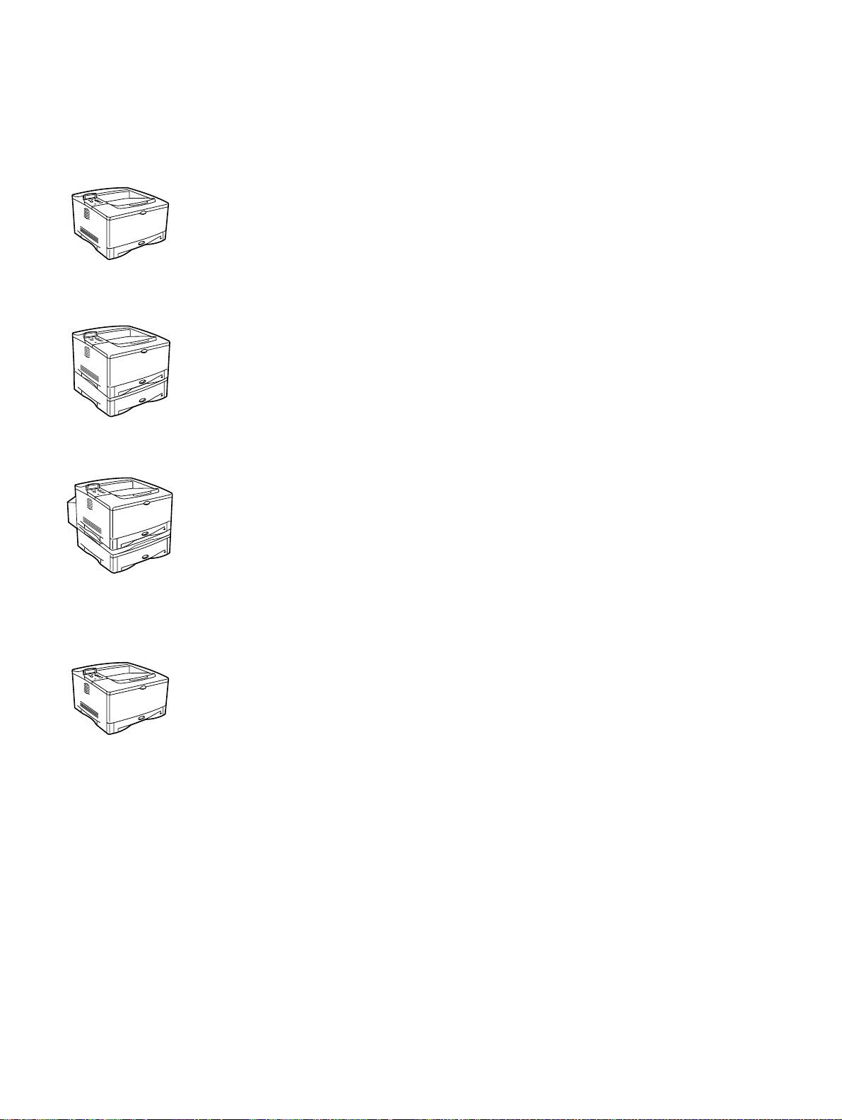
The printer is available in four configurations, as described here.
HP LaserJet 5100 printer
The HP LaserJet 5100 printer (product number: Q1860A) is a 22 pages per minute (pp m) laser
printer that comes standard with a 100-sheet multipurpose Tray 1, a 250-sheet Tray 2, and
16 MB of memory. It is designed for workgroups and can print on paper sizes up to A3 and 11
by 17 inches (279 by 432 mm).
HP LaserJet 5100tn printer
The HP LaserJet 5100tn printer (product number: Q1861A) is a 22 ppm laser printer that
comes standard with a 100-sheet multipurpose Tray 1, a 250-sheet Tray 2, a 500-sheet feeder,
32 MB of memory, and an HP Jetdirect print server for connecting to a fast Ethernet (10/
100Base-TX) network. It is designed f or ne twork users and can print full-b leed images on paper
sizes up to A3 and 11 by 17 inches (279 by 432 mm).
HP LaserJet 5100dtn printer
The HP LaserJet 5100dtn printer (product number: Q1862A) is a 22 ppm laser printer that
comes standard with a 100-sheet multipurpose Tray 1, a 250-sheet Tray 2, a 500-sheet feeder,
32 MB of memory, an HP Jetdirect print server for connecting to a fast Ethernet (10/100BaseTX) network, an embedded Web server DIMM for remote printer management, and a duplex
printing accessory for printing on two sides of a sheet of print media. The printer is designed for
network users and can print full-b leed images on pape r sizes up t o A3 and 11 b y 17 inches (279
by 432 mm).
HP LaserJet 5100Le printer
This printer (product number: Q1863A) is a 22 ppm laser printer that comes standard with a
100-sheet multipurpose Tray 1, a 250-sheet Tray 2, and 16 MB of memory. The printer can print
full-bleed images on paper sizes up to A3 and 11 by 17 inches (279 by 432 mm). Paperhandling and EIO accessories are not available for the HP LaserJet 5100Le printer
Q1860-90918 Chapter 1 Printer description 17
www.GovTechMedia.com
Page 20

Table 2. Comparison of HP LaserJet 5100 Series printers
HP LaserJet 5100
(Q1860A)
Ethernet 10-T/ 10-2 optional standard standard not available
Input bins (standard/
maximum
Standard RAM 16 MB internal 32 MB 32 MB 16 MB
250-sheet feeders
(Tray 2, Tray 3)
500-sheet feeder optional standard standard N/A
EIO hard disk optional optional optional N/A
Duplexer optional optional standard N/A
LocalTalk optional optional optional N/A
Processor 300 MHz 300 MHz 300 MHz 300 MHz
2/4 3/4 3/4 2/2
1 standard
1 optional
HP LaserJet 5100tn
(Q1861A)
1 standard
1 optional
HP LaserJet 5100dtn
(Q1862A)
1 standard
1 optional
HP LaserJet 5100 LE
(Q1863A)
1 standard
18 Printer description Q1860-90918
www.GovTechMedia.com
Page 21
Identification
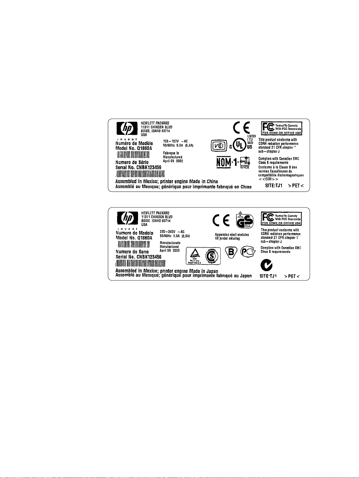
Model and serial numbers
The model and serial numbers are listed on identification labels that are located inside the top
cover . The serial number is alphanumeric , such as USB000 0146 for the HP LaserJet 5100 series
printer.
The serial number contains information about the origin location, as well as the revision lev el, the
production code, and the production number of the printer.
The labels also contain power rating and regulatory information as shown in figure 1.
Figure 1. Sample identification labels
Q1860-90918 Chapter 1 Printer description 19
www.GovTechMedia.com
Page 22

Site requirements
Environmental and power requirements
The following en vironmental specif ications must be maint ained to ensure the pro per operat ion of
the printer. Consider the following points before installing the printer:
Install the printer in a well-ventilated, dust-free area.
Install the printer on a hard, flat, and continuous surface on which all four printer feet are
level. Do not install the printer on carpet or other soft surfaces.
Make sure that adequate power is supplied. The printer power requirements are listed in
table 3.
Install the printer where temperature and humid it y are st able, and away from wa te r so ur ce s,
humidifiers, air conditioners, refrigerators, or other major appliances.
Install the printer away from direct sunlight, open flames, or ammonia fumes. If the printer is
placed near a window, make sure the window has a curtain or blind to block any direct
sunlight.
Install the printer with enough space around it for proper access and ventilation.
Install the printer away from the direct flow of exhaust from air-ventilation systems.
Table 3. Power requirements
Watts (average maximum,
based on HP LaserJet 5100dtn
printer)
standby = 24
Pow erSave on = < 30 (ENERGY
STAR®)*
printer off = 0
standby = 29
Pow erSave on = < 30 (E
STAR®)*
printer off = 0
NERGY
Volts Frequency
100 to 127 Vac
(+/-10%)
220 to 240 Vac
(+/-10%)
50 to 60 Hz
(+/-3 Hz)
50 to 60 Hz
(+/-3 Hz)
Amps
(current
rating)
5.4 amps 6 amps printing = 480
2.5 amps 3 amps printing = 515
Amps (rated
short-term
current)
*ENERGY STAR is a U.S. registered service mark of the United Stat es Environmental Protect ion
Agency.
20 Printer description Q1860-90918
www.GovTechMedia.com
Page 23
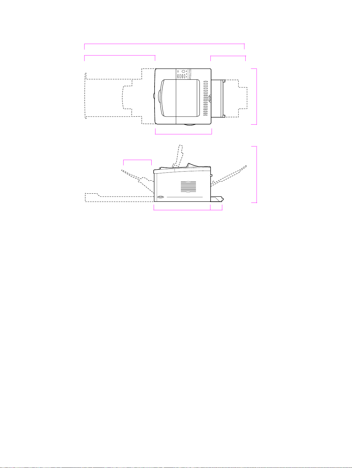
Space requirements
139.8 cm (55 in)
27.0 cm (10.6 in)
30.3 cm (11.9 in)62.5 cm (24.6 in)
47.5 cm (18.7 in) 47.3 cm (18.6 in)
47.0 cm (18.5 in)
47.0 cm (18.5 in)
11.0 cm (4.3 in)
Figure 2. Printer dimensions—HP LaserJet 5100 printer and HP LaserJet 5100Le printer
Q1860-90918 Chapter 1 Printer description 21
www.GovTechMedia.com
Page 24
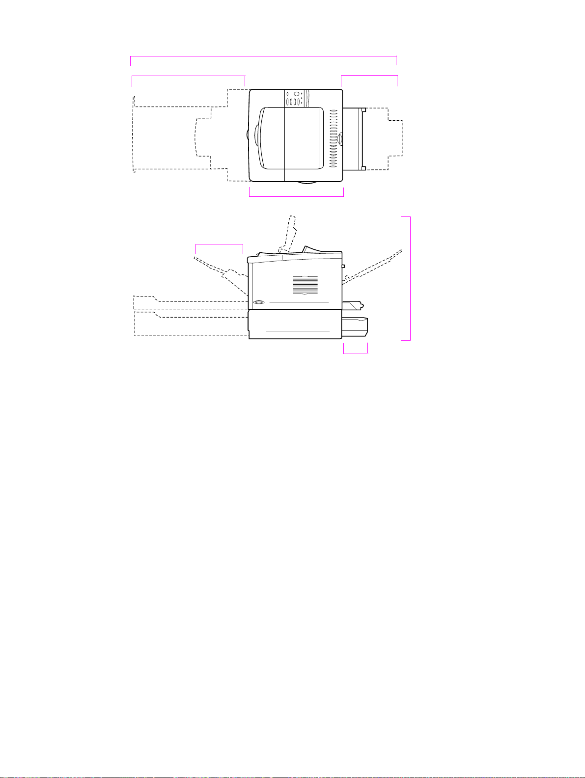
139.8 cm (55 in)
62.5 cm (24.6 in)
27.0 cm (10.6 in)
30.3 cm (11.9 in)
47.0 cm (18.5 in)
62.0 cm (24.4 in)
15.5 cm (6.1 in)
Figure 3. Printer dimensions—HP LaserJet 5100tn printer and HP LaserJet 5100dtn printer
22 Printer description Q1860-90918
www.GovTechMedia.com
Page 25
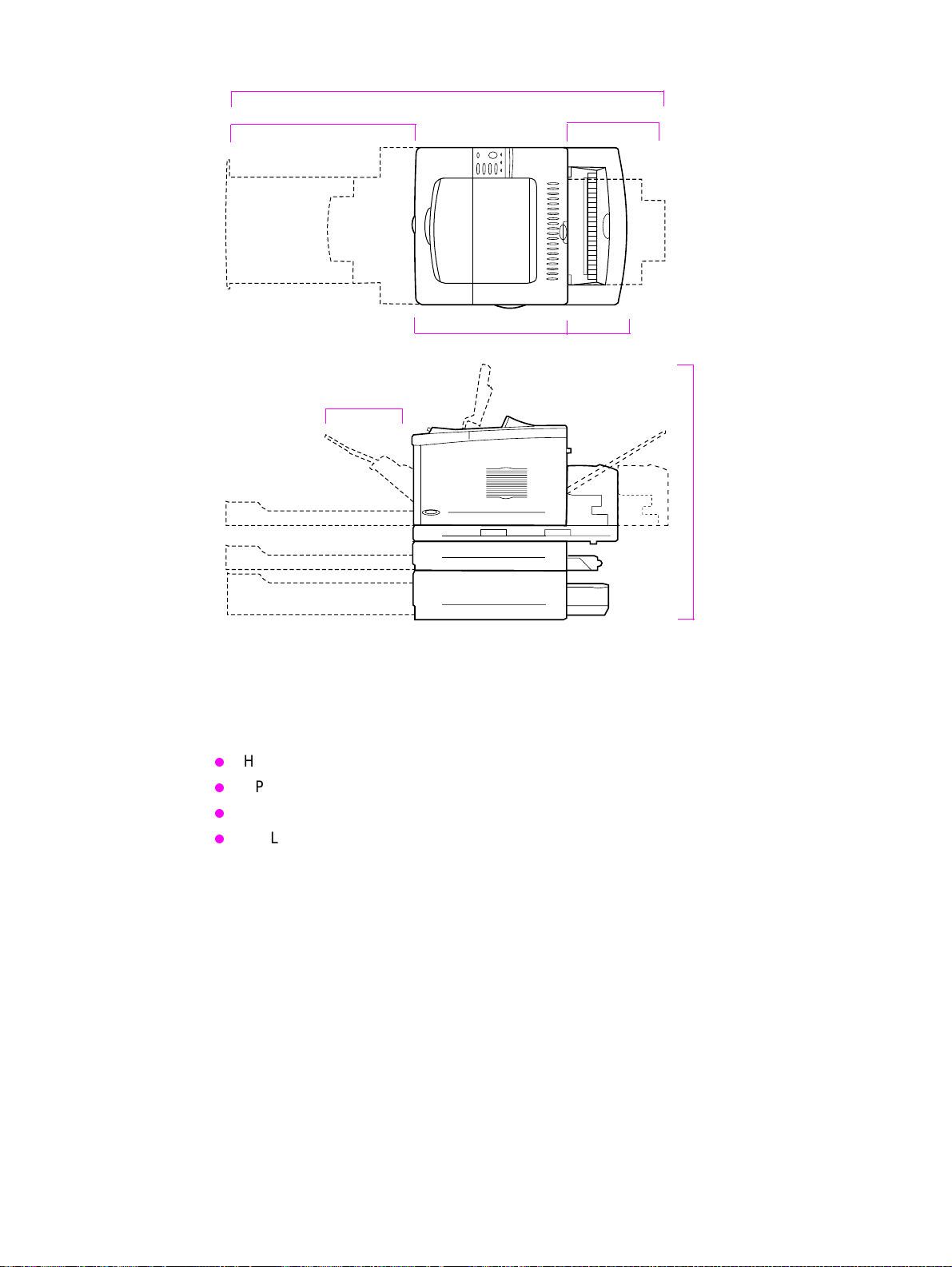
139.8 cm (55 in)
62.5 cm (24.6 in)
27.0 cm (10.6 in)
47.0 cm (18.5 in)
30.3 cm (11.9 in)
16.6 cm (6.5 in)
75.5 cm (29.7 in)
Figure 4. Printer dimensions, HP LaserJet 5100 series printer with accessories
Printer weight (without toner cartridge)
HP LaserJet 5100 printer: 23 kg (50 lb)
HP LaserJet 5100tn printer with optional 500-sheet feeder: 34 kg (75 lb)
HP LaserJet 5100dtn printer with duplexer and optional 500-sheet feeder: 52 kg (114 lb)
HP LaserJet 5100Le printer: 23 kg (50 lb)
Q1860-90918 Chapter 1 Printer description 23
www.GovTechMedia.com
Page 26

Environmental requirements
Table 4. Environmental specif ications
Item Operating Storage
Temperature 10° to 32° C (50° to 91° F) -20° to 60° C (-4° to 140° F)
Relative humidity (RH) 20 to 80 percent RH (with no
10 percent to 95 percent RH
condensation)
Table 5. Acoustics specif ications
Printer state Sound power Bystander position Operator position
Printing at 22 ppm L
Printing at 11 ppm L
PowerSave L
*Maximum values are based on the HP LaserJet 5100dtn printer.
= 6.8 bels (A) L
WAd
= 6.4 bels (A) L
WAd
= 4.4 bels (A) L
WAd
=53 dB L
pAm
=50 dB L
pAm
=32 dB L
pAm
=60 dB maximum*
pAm
=56 dB maximum*
pAm
=37 dB maximum*
pAm
24 Printer description Q1860-90918
www.GovTechMedia.com
Page 27

Paper specifications
The following tables show paper specifications for the printer.
Table 6. Paper specifications, Tra y 1
Supported paper Dimensions
Minimum size
(custom)
Maximum size
(custom)
Transparencies
Labels Thickness:
Envelopes 75 to 105 g/m
1. The printer supports a wide range of paper sizes. Check the printer software for supported sizes. To print
custom-size paper see the user’s guide.
2. Capacity might vary depending on paper weight and thickness, and environmental conditions.
1
76 by 127 mm
(3 by 5 inches)
312 by 470 mm
(12.28 by 18.5 inches)
Same as minimum
and maximum paper
sizes as listed above.
Weight Capacity
60 to 199 g/m
2
(16 to 53 lb)
Thickness:
0.099 to 0.114 mm
(0.0039 to 0.0045 in)
0.127 to 0.178 mm
(0.005 to 0.007 in)
2
(20 to 28 lb)
100 sheets of 75-g/m
(20-lb) paper
75 transparencies
50 labels
10 envelopes
2
2
Table 7. Paper specifications, Tray 2 or other 250-sheet feeder
Supported Paper Dimensions
1
Letter 216 by 279 mm
(8.5 by 11 in)
A4 210 by 297 mm
(8.3 by 11.7 in)
Executive 191 by 267 mm
(7.3 by 10.5 in)
Legal 216 by 356 mm
(8.5 by 14 in)
B5 (JIS) 182 by 257 mm
(7.2 by 10 in)
A5 148 by 210 mm
(5.8 by 8.2 in)
11 by 17 279 by 432 mm
(11 by 17 in)
A3 297 by 420 mm
(11.7 by 16.5 in)
B4 (JIS) 257 by 364 mm
(10.1 by 14.3 in)
1. The printer supports a wide range of media sizes. Check the printer software for supported sizes.
2. Capacity might vary depending on media weight and thickness, and environmental conditions.
Weight Capacity
60 to 105 g/m
(16 to 28 lb)
2
250 sheets of 75-g/m
(20-lb) paper
50 to 100 transparencies
2
2
Q1860-90918 Chapter 1 Printer description 25
www.GovTechMedia.com
Page 28

Table 8. Paper specifications, 500-sheet feeder
Supported paper Dimensions
Letter
Letter-R
A4
A4-R
3
3
Executive 191 by 267 mm
Legal 216 by 356 mm
B5 (JIS) 182 by 257 mm
A5 148 by 210 mm
11 by 17 279 by 432 mm
A3 297 by 420 mm
B4 (JIS) 257 by 364 mm
Minimum Size
(Custom
4
)
216 by 279 mm
(8.5 by 11 inches)
210 by 297 mm
(8.3 by 11.7 inches)
(7.3 by 10.5 inches)
(8.5 by 14 inches)
(7.2 by 10 inches)
(5.8 by 8.2 inches)
(11 by 17 inches)
(11.7 by 16.5 inches)
(10.1 by 14.3 inches)
148 by 210 mm
(5.8 by 8.3 inches)
1
Weight Capacity
60 to 105 g/m
(16 to 28 lb)
2
2
500 sheets of 75-g/m
2
(20-lb) paper
50 to 100 transparencies
Maximum Size
(Custom
1. The printer supports a wide range of media sizes. Check the printer software for supported sizes.
2. Capacity may vary depending on media weight and thickness, and environmental conditions.
3. To print rotated paper, see the user’s guide.
4. To print custom-size paper, see the user’s guide.
4
)
297 by 432 mm
(11.7 by 17 inches)
Table 9. Paper specifications, duplexer
Dimensions
1
Minimum 148 by 210 mm (5.8 by 8.3 inches) 60 to 105 g/m2 (16 to 28 lb)
Maximum 297 by 432 mm (11.7 by 17 inches)
1. The printer supports a wide range of media sizes. Check the printer software for supported sizes.
Weight
Supported types of paper
The printer supports a wide variety of media, such as:
plain
letterhead
prepunched
bond
rough
vellum
preprinted
transparency
labels
recycled
card stock
user-defined (5 types)
26 Printer description Q1860-90918
www.GovTechMedia.com
color
Page 29

Guidelines for using paper
For best results, use conventional 75-g/m2 (20-lb) paper. Make sure the paper is of good quality
and free of cuts, nicks, tears, spots, loose particles, dust, wrinkles, voids, and curled or bent
edges.
Some paper causes print-quality problems, jamming, or damage to the printer.
For more specific information, see “Image defects” on page 209.
Table 10. Media issues
Symptom Problem with paper Solution
Poor print quality or toner
adhesion.
Problems with feeding.
Dropouts, jamming, curl. Stored improperly. Store paper flat in its moisture-proof
Increased gray background
shading.
Excessive curl.
Problems with feeding.
Jamming, damage to the printer. Cutouts or perforations. Do not use paper with cutouts or
Problems with feeding. Ragged edges. Use higher quality paper.
Too moist, too rough, too
smooth, or embossed; faulty
paper lot.
Too heavy. Use lighter paper.
Too moist, wrong grain direction,
or short-grain construction.
Try another kind of paper, between
100 and 250 Sheffield, and with 4%
to 6% moisture content.
wrapping.
Open the rear output bin.
Open the rear output bin.
Open the rear output bin.
Use long-grain paper.
FUSER MODE=LOW.
Set
perforations.
Note Do not use letterhead paper that is printed with low-temperature inks, su ch as those used in some
types of thermography.
Do not use raised letterhead.
The printer uses heat and pressure to f use toner to the p aper. Make su re that an y colored paper
or preprinted forms use inks that are compatible with the printer’s temperature (200° C or 392° F
for 0.1 second).
Q1860-90918 Chapter 1 Printer description 27
www.GovTechMedia.com
Page 30

Paper weight equivalence table
Use this table to determine approximate equivalent points in weight specifications other than
U.S. bond weight. For example, to determine the equivalent of 20-lb U.S. bond-w eight paper in
U.S. cover weight , locate the bond weight (in row 3, second column) and scan across the row to
the cover weight (i n the fourth column). The equivalent is 28 lb.
Shaded areas indicate a standard weigh t for that gra de.
U.S.
postcard
thickness
(mm)
1
bond
weight (lb)
U.S.
U.S.
text/book
weight (lb)
U.S.
cover
weight (lb)
U.S.
bristol
weight (lb)
U.S.
index
weight (lb)
U.S.
tag
weight (lb)
Europe
metric
weight
(g/m2)
Japan
metric
weight
(g/m2)
1 16 41 22 27 33 37 60 60
2 17432429353964
3
4 215430364449
20 50 28 34 42 46 75 75
80 80
5 22563138465181
6
7 276837455561
8
9
24 60 33 41 50 55 90 90
100 100
28 70 39 49 58 65 105 105
32 80 44 55 67 74 120 120
10 34 86 47 58 71 79 128
11
12
.18 39 100 55 67 82 91 148 148
36 90 50 62 75 83 135 135
13 .19 42 107 58 72 87 97 157
14
15 .23 47 119
.20 43 110 60 74 90 100 163 163
65 80 97 108 176 176
64
81
128
157
16 53 134 74 90
1. U.S. postcard measurements are approximate. Use for reference only.
110 122 199 199
28 Printer description Q1860-90918
www.GovTechMedia.com
Page 31

Labels
CAUTION To avoid damaging the printer, use only lab els that are recommended for use in laser printers.
If you have problems printing labels, use Tray 1 and open the rear output bin.
Never print on the same sheet of labels more than once .
When selecting labels, consider the quality of each component:
Adhesives: The adhesive material shou ld be stable at 200 ° C (392° F), the printer’s
maximum temperature.
Arrangement: Only use labels that have no exposed backing between them. Labels can
peel off of sheets that have spaces between the labels, cau sing serious jams.
Curl: Before printing, labels must lie flat with no more than 13 mm (0.5 inch) of curl in any
direction.
Condition: Do not use labels that have wrinkles, bubbles, or other indications of separation.
Transparencies
Transparencies used in the printer must be able to withstand 200° C (392° F), the printer’s
maximum temperature. For best results, close the rear output bin to print transparencies to the
top output bin.
CAUTION To avoid damaging the printer, use only transparencies that are recommended for use in
monochrome laser printers.
If you have problems printing on transparencies, use Tray 1.
Vellum
V ellum is typically a special lightweight paper similar to parchment. Print vellum from Tray 1 only,
and open the rear output bin. Do not print on both sides of vellum.
Vellum used in the printer must be able to withstand 200° C (392° F), the printer’s maximum
temperature.
Envelopes
Always print envelopes from Tray 1. To help prevent envelopes from wrinkling or jamming, open
the rear output bin.
Envelope construction
Envelope construction is critical. Envelope fold lines can vary considerably, not only between
manufacturers, but also within a box from the same manufacturer. Successful printing on
envelopes depends upon the quality of the envelopes. When selecting envelopes, consider the
following components:
Q1860-90918 Chapter 1 Printer description 29
www.GovTechMedia.com
Weight: The weight of the envelope paper should not exceed 105 g/m2 (28 lb), or jamming
can result.
Construction: Before printing, env elopes should lie flat with less than 6 mm (0.25 inch) curl,
and should not contain air. (Envelopes that trap air can cause problems.)
Condition: Make sure envelopes are not wrinkled, nicked, or otherwise damaged.
Size: Tray 1, the multipurpose tray, handles envelope sizes from 76 by 127 mm (3 by 5
inches) to 312 by 470 mm (12.28 by 18.5 inches).
Page 32

Envelopes that have double side seams
Double-side-seam construction has v ertical seams at both ends of the envelope rather than
diagonal seams. This style can be more likely to wrinkle . Be sure that the seam extends all the
way to the corner of the envelope as illustrated below.
Acceptable
Unacceptable
Figure 5. Envelopes with double side seams
Envelopes that have adhesive strips or flaps
Envelopes that have a peel-off adhesive strip or more than one flap that f olds over to seal must
use adhesives that are compatible with the heat and pressure in the printer. The extra flaps and
strips might cause wrinkling, creasing, or jams.
Envelope marg ins
The following tabl e shows typical address margins for a Commercial #10 or DL envelope.
Table 11. Envelope margins
Type of address Top margin Left margin
Return address 15 mm (0.6 inch) 15 mm (0.6 inch)
Delivery address 51 mm (2 inches) 89 mm (3.5 inches)
Note For the best print quality , position ma rgins no closer than 15 mm (0.6 inch) f rom the edges of the
envelope.
Envelope storage
Proper storage of envelopes helps contribute to good print quality. Envelopes should be stored
flat. If air is trapped in an envelope, creating an air bubble, the envelope might wrinkle during
printing.
30 Printer description Q1860-90918
www.GovTechMedia.com
Page 33

Card stock and heavy paper
Many types of card stock can be printed from Tray 1, including inde x cards and post cards . Some
card stock performs better than others because its construction is better suited for feeding
through a laser printer.
For optimum printer performance, do not use paper heavier than 199 g/m
105 g/m
2
(28 lb) in other tra ys . Paper that is too hea vy might cause misf eed s, sta cking prob lems ,
paper jams, poor toner fusing, poor print quality, or excessive mechanical wear.
Note Printing on heavier paper might be possible if the tray is not filled to capacity, and if paper with a
smoothness rating of 100 to 180 Sheffield is used.
Card stock construction
Smoothness: 135- to 199-g/m2 (36 to 53 lb) card stock sh ould have a smoothness r at ing o f
100 to 180 Sheffield; 60- to 135-g/m
rating of 100 to 250 Sheffield.
Construction: Card stock should lie flat with less than 5 mm (0.2 inch) of curl.
Condition: Make sure card stock is not wrinkled, nicked, or otherwise damaged.
Sizes: Use only card stock within the following size ranges:
• minimum: 76 by 127 mm (3 by 5 inches)
• maximum: 312 by 470 mm (12.28 by 18.5 inches)
2
(16 to 36 lb) card stock should have a smoothness
2
(53 lb) in Tray 1 or
Note Before loading card stock in Tray 1, make sure it is regular in shape and not damaged. Also, make
sure the cards are not stuck together.
Card stock guidelines
If cards curl or jam, try printing from Tray 1 and opening the rear output bin.
Set margins at least 2 mm (0.08 inch) away from the edges of the paper.
Q1860-90918 Chapter 1 Printer description 31
www.GovTechMedia.com
Page 34

Safety information
Laser safety statement
The Center for Devices and Radiological Health (CDRH) of the U.S. Food and Drug
Administration has implemented regulations for laser products manufactured since August 1,
1976. Compliance is mandatory for products marketed in the United States. The printer is
certified as a “Class 1” laser product under the U.S. Department of Health and Human Services
(DHHS) Radiation Performance Standard according to the Radiation Control for Health and
Safety Act of 1968. Since ra diation emitted inside the printer is completely confined within
protective housings and external covers, the laser beam cannot escape during any phase of
normal user operation.
WARNING! Using controls, making adjustments , or perf o rming procedures other than those specified in this
service manual might result in exposure to hazardous radiation.
Canadian DOC regulations
Complies with Canadian EMC Class B requirements.
«Conforme á la classe B des normes canadiennes de compatibilité électromagnétiques.
«CEM».»
FCC regulations
This equipment has been tested and found to comply with the limits for a Class B digital device,
pursuant to Part 15 of the FCC rules. These limits are designed to pro vide reasonab le protect ion
against harmful interference in a residential installation . This equipment generates, uses, and
can radiate radio frequency energ y. If this equipment is not installed and used in accordance with
the instructions, it may cause harmful interf erence to r adio communicat ions. Ho we ver, there is no
guarantee that interference will not occur in a particular installation. If this equipment does cause
harmful interference to radio or television reception, which can be determined by turning the
equipment off and on, the user is encouraged t o try to correct the interference by one or more of
the following measures:
Reorient or relocate the receiving antenna.
Increase the separation between the equipment and the receiver.
Connect the equipment to an outlet on a different circuit from that to which the receiver is
connected.
Consult your dealer or an experienced radio and television technician.
Note Any changes or modifications to the printer that are not expressly a pprov ed by HP could v oid the
user’s authority to operate this equipment.
Use of a shielded interface cable is required to comply with the Class B limits of Part 15 of FCC
rules.
32 Printer description Q1860-90918
www.GovTechMedia.com
Page 35

Laser statement for Finland
Luokan 1 laserlaite
Klass 1 Laser Apparat
HP LaserJet 5000, 5000 N, 5000 GN -laserkirjoitin on käyttäjän kannalta turvallinen luokan 1
laserlaite. Normaalissa käytössä kirjoittimen suojakotelointi estää lasersäteen pääsyn laitteen
ulkopuolelle. Laitteen turvallisuusluokka on määritetty standardin EN 60825 -1 ( 1994) mu kaise sti.
V aroitus!
Laitteen käyttäminen muulla kuin käyttöohjeessa mainitulla tavalla saattaa altistaa käyttäjän
turvallisuusluokan 1 ylittävälle näkymättömälle lasersäteilylle.
V arning!
Om apparaten används på annat sätt än i bruksanvisning specificerats, kan användar en utsättas
för osynlig laserstrålning, som överskrider gränsen för laserklass 1.
HUOLTO
HP LaserJet 5000, 5000 N, 5000 GN -kirjoittimen sisällä ei ole käyttäjän huollettavissa olevia
kohteita. Laitteen saa avata ja huoltaa ainoastaan sen huoltamiseen koulutettu henkilö.
Tällaiseksi huoltotoimenpiteeksi ei katsota väriainekasetin vaihtamista, paperiradan puhdistusta
tai muita käyttäjän käsikirjassa lueteltuja, käyttäjän tehtäväksi tarkoitettuja ylläpitotoimia, jotka
voidaan suorittaa ilman erikoistyökaluja.
Varo!
Mikäli kirjoittimen suojakotelo a v ataan, olet alt tiina näkymättömälle lasersäteilylle laitteen ollessa
toiminnassa. Älä katso säteeseen.
V arning!
Om laserprinterns skyddshölje öppnas då apparaten är i funktion, utsättas användaren för
osynlig laserstrålning. Betrakta ej strålen.
Tiedot laitteessa käytettävän laserdiodin säteilyominaisuuksista:
Aallonpituus 775-795 nm
Teho 5 mW
Luokan 3B laser
Material Safety Data Sheet
Material Safety Data Sheets can be obtained from the HP LaserJet Supplies website at
http://www.hp.com/go/msds
.
Q1860-90918 Chapter 1 Printer description 33
www.GovTechMedia.com
Page 36

Environmental product stewardship
Protecting the environment
Hewlett-Packard Company is committed to providing quality products in an envir onmentallysound manner. The printer has been designed to minimize impacts on the environment.
The printer design eliminates:
Ozone production
Energy
consumption
The printer does not use high-voltage corona wires in the
electrophotographic process and therefore generates no appreciable
ozone gas (O
). Instead, this printer uses charging rollers in the toner
3
cartridge and in the print engine.
This HP LaserJet printer design reduces:
Power usage drops significantly while in PowerSave mode, which saves
natural resources and sav es money with out affe cting the high perf ormance
of this printer. This printer qualifies for E
NERGY STAR
program to encourage the development of energy-efficient off ice products.
E
NERGY STAR is a U.S. registered service mark
owned by the U.S. government. As an E
partner, Hewlett-Packard Company has determined
that this printer meets E
energy efficiency
http://www.energystar.gov/
. For more information, see
NERGY STAR Guidelines for
®
, which is a voluntary
NERGY STAR
34 Printer description Q1860-90918
www.GovTechMedia.com
Page 37

2 Service approach
Overview
Regulatory information . . . . . . . . . . . . . . . . . . . . . . . . . . . . . . . . . . . . . . . . . . . . . . . . . . . . . . . 36
Service approach . . . . . . . . . . . . . . . . . . . . . . . . . . . . . . . . . . . . . . . . . . . . . . . . . . . . . . . . . . . 36
Parts and supplies . . . . . . . . . . . . . . . . . . . . . . . . . . . . . . . . . . . . . . . . . . . . . . . . . . . . . . . 36
Warranty. . . . . . . . . . . . . . . . . . . . . . . . . . . . . . . . . . . . . . . . . . . . . . . . . . . . . . . . . . . . . . . 36
Limited warranty for the print cartridge. . . . . . . . . . . . . . . . . . . . . . . . . . . . . . . . . . . . . . . . 36
Service and support . . . . . . . . . . . . . . . . . . . . . . . . . . . . . . . . . . . . . . . . . . . . . . . . . . . . . . 37
Worldwide service and support offices. . . . . . . . . . . . . . . . . . . . . . . . . . . . . . . . . . . . . . . . 38
Q1860-90918 Chapter 2 Service approach 35
www.GovTechMedia.com
Page 38

Regulatory information
For regulatory information and requirements, FCC regulations, and declaration of conformity,
please see the start guide.
For environmental product stewardship program information, please see the use guide.
Service approach
Repair of the printer normally begins with a three-step process:
1 Isolate the prob lem to the major system (the host co mputer , the network and/or server , or t he
printer).
2 Determine whether the problem is located in the print engine or an accessory device.
3 Troubleshoot the problem using the troubleshooting information in chapter 7.
Once a faulty part is located, repair is usually accomplished by assembly-level replacement of
field replaceable units (FRUs). Some mechanical assemblies can be repaired at the
subassembly le vel. He wlett-P ac kard does not support replacement of components on the printed
circuit assemblies.
Parts and supplies
Information about ordering
Chapter 8 of this manual contains field replacement unit (FRU) and replacement part numbers.
Replacement parts can be ordered from the HP Customer Support (HPCS) organization.
Chapter 8 of this manual also contains information about products specifically designed for this
printer. Order accessories from HPCS.
Note See "Worldwide service and support offices" on page 38 to find information f or a local HP office
in the appropriate region.
HPCS phone listings
HPCS (for U.S.)
(1) (800) 752-0900
HPCS (for Canada)
(1) (800) 387-3867
HPCS (for Europe)
(49 7031) 142253
Exchange program
HP might offer remanufactured assemblies for parts. These can be ordered through HPCS.
36 Service approach Q1860-90918
www.GovTechMedia.com
Warranty
For warranty information and requirements, see the start guide.
Limited warranty for the print cartridge
For print cartridge warranty information, see the start guide.
Page 39

Service and support
World Wide Web
Print drivers, updated HP MFP firmware, and product and support information can be obtained
from the following URLs:
U.S., http://www.hp.com/support/lj5100
Europe, http://www.hp.com/support/lj5100
China, ftp://www.hp.com.cn/support/lj5100
Japan, ftp://www.jpn.hp.com/support/lj5100
Korea, http://www.hp.co.kr/support/lj5100
Taiwan, http://www.hp.com.tw/support/lj5100, or the local driver website, http://
www.dds.com.tw
HP support assistant CD-ROM
This support tool offers a comprehensive online information system designed to provide
technical and product information about He wlett-Packard prod ucts. To subscribe to this quarterly
service in the U.S. or Canad a, ca ll (1) ( 80 0) 457 -1 762. In Hong Kong SAR, Indonesia, M alaysia,
or Singapore, call Mentor Media at (65) 740-4477.
HP-authorized resellers and support
To locate HP-authorized resellers and support, call (1) (800) 243-9816 in the U.S. or
(1) (800) 387-3867 in Canada. See "Worldwide service and support offices" on page 38 for
areas outside of North America.
HP service agreements
Call (1) (800) 743-8305 in the U.S. or (1) (800) 268-1221 in Canada.
HP PartnerCare
You can use the following information to contact HP PartnerCare:
PartnerShip Web. http://www.partner.americas.hp.com
e-mail at websupport@mnl.com
Connect Online. http://www.connect-online.hp.com
e-mail at PTS, INFOLINE (HP-Germany, exgen1)
Asia-Pacific countries/regions. http://partnercare.asiapac.hp.com/
Canada Partner. http://www.canada.hp.com
Latin America. http://www.conecta.latinamerica.hp.com
e-mail at SUPPORT-TEAM,LAR (HP-Miami, exgen1 )
Q1860-90918 Chapter 2 Service approach 37
www.GovTechMedia.com
Page 40

Worldwide service and support offices
For the U.S., call (1) (208) 323-2551 Mo nday through Friday from 6 A.M. to 6 P.M., Mountain
time.
For Canada, call (1) (905 ) 206-4663 or (1) (800) 387-3867 Monday through Friday from 8
A.M. to 8 P.M., Mountain time.
For customers outside of North America, use the following list and call the appropriate
telephone number f or the country or region.
Europe
Austria: 43 (0)810 00 6080
Belgium
Dutch: 32 (0)2 626-8806
French: 32 (0)2 626-8806
Czech Republic: 42 (0)2 6130 7310
Denmark: +45 39 29 4099
International English: +44 (0 )207 512 52 02
Finland: 358 (0)203 47 288
France: 33 (0)1 43 62 34 34
Germany: 49 (0)180 52 58 143
Greece: +30 (0)1 619 64 11
Hungary: +36 (0)1 382-1111
Ireland: +353 (0)1 662 5525
Italy: 39 02 264 10350
Netherlands: 31 (0)20 606 8751
Norway: 47 22 11 6299
Poland: +48 22 865 98 00
Portugal: 351 21 3176333
Romania: +40 1 315 44 42 (or 01 3154442)
Russian Federation
Moscow: +7 095 797 3520
St. Petersburg: +7 812 346 7997
Spain: +34 902 321 123
Sweden: +46 (0)8 619 2170
Switzerland: +41 (0)848 80 11 11
Turkey: +90 212 221 69 69
Ukraine: +7 (380-44) 490-3520
U.K.: +44 (0)207 512 52 02
38 Service approach Q1860-90918
www.GovTechMedia.com
Africa and Middle East
Egypt: +202 7956222
International English: +44 (0 )207 512 52 02
Israel: +972 (0)9 9524848
South Africa
Inside RSA: 086 000 1030
Outside RSA: +27-11 258 9301
United Arab Emirates, Bahrain, Jordan, Kuwait, Lebanon, Oman, Palestine, Qatar, Saudi Arabia,
and Yemen: 971 4 883 8454
Page 41

Asia-Pacific countries/regions
Australia: (03) 8877 8000
China: +86 (0)10 6564 5959
Hong Kong SAR: +85 (2) 2802 4098
India: +91 11 682 6035
Indonesia: +62 (21) 350-3408
Japan: +81 3 3335-8333
Republic of Korea
Seoul: +82 (2) 3270-0700
Outside Seoul: 080 999-0700
Malaysia: +60 (3) 295 2566
New Zealand: +64 (9) 356 6640
Philippines: +63 (2) 867 3551
Singapore: +65 272 5300
Taiwan: +886 (2) 2717 0055
Thailand: +66 (2) 661 4000
Vietnam: +84 (0) 8 823 4530
Latin America
Argentina: 0810-555-5520
Brazil
Greater Sao Paulo: (11) 3747-7799
Outside Greater São Paulo: 0800-157751
Chile: 800-22-5547
Guatemala: 800-999-5305
Mexico
Mexico City: 52-58-9922
Outside Mexico City: 01-800-472-6684
Peru: 0-0800-10111
Puerto Rico: 1-877-2320-589
Venezuela
Caracas: 207 8488
Outside Caracas: 800 47 777
Q1860-90918 Chapter 2 Service approach 39
www.GovTechMedia.com
Page 42

40 Service approach Q1860-90918
www.GovTechMedia.com
Page 43

3 Printer operation
Overview
Using the control panel . . . . . . . . . . . . . . . . . . . . . . . . . . . . . . . . . . . . . . . . . . . . . . . . . . . . . . . 42
Control panel layout . . . . . . . . . . . . . . . . . . . . . . . . . . . . . . . . . . . . . . . . . . . . . . . . . . . . . . 42
Control panel lights. . . . . . . . . . . . . . . . . . . . . . . . . . . . . . . . . . . . . . . . . . . . . . . . . . . . . . . 42
Control panel keys . . . . . . . . . . . . . . . . . . . . . . . . . . . . . . . . . . . . . . . . . . . . . . . . . . . . . . . 43
Settings and defaults . . . . . . . . . . . . . . . . . . . . . . . . . . . . . . . . . . . . . . . . . . . . . . . . . . . . . 44
Control panel menus. . . . . . . . . . . . . . . . . . . . . . . . . . . . . . . . . . . . . . . . . . . . . . . . . . . . . . . . . 45
Private/stored jobs menu . . . . . . . . . . . . . . . . . . . . . . . . . . . . . . . . . . . . . . . . . . . . . . . . . . 46
Information menu . . . . . . . . . . . . . . . . . . . . . . . . . . . . . . . . . . . . . . . . . . . . . . . . . . . . . . . . 47
Paper-handling menu . . . . . . . . . . . . . . . . . . . . . . . . . . . . . . . . . . . . . . . . . . . . . . . . . . . . . 48
Print-quality menu. . . . . . . . . . . . . . . . . . . . . . . . . . . . . . . . . . . . . . . . . . . . . . . . . . . . . . . . 50
Printing menu . . . . . . . . . . . . . . . . . . . . . . . . . . . . . . . . . . . . . . . . . . . . . . . . . . . . . . . . . . . 51
Configuration menu . . . . . . . . . . . . . . . . . . . . . . . . . . . . . . . . . . . . . . . . . . . . . . . . . . . . . . 53
I/O menu. . . . . . . . . . . . . . . . . . . . . . . . . . . . . . . . . . . . . . . . . . . . . . . . . . . . . . . . . . . . . . . 55
EIO menu (HP LaserJet 5100tn and 5100dtn printers) . . . . . . . . . . . . . . . . . . . . . . . . . . . 56
Resets menu . . . . . . . . . . . . . . . . . . . . . . . . . . . . . . . . . . . . . . . . . . . . . . . . . . . . . . . . . . . 58
Service mode . . . . . . . . . . . . . . . . . . . . . . . . . . . . . . . . . . . . . . . . . . . . . . . . . . . . . . . . . . . . . . 59
Service menu . . . . . . . . . . . . . . . . . . . . . . . . . . . . . . . . . . . . . . . . . . . . . . . . . . . . . . . . . . . 59
Setting the page count, maintenance count, and serial number . . . . . . . . . . . . . . . . . . . . 60
Cold reset paper size . . . . . . . . . . . . . . . . . . . . . . . . . . . . . . . . . . . . . . . . . . . . . . . . . . . . . 62
Diagnostics. . . . . . . . . . . . . . . . . . . . . . . . . . . . . . . . . . . . . . . . . . . . . . . . . . . . . . . . . . . . . 62
Clear event log . . . . . . . . . . . . . . . . . . . . . . . . . . . . . . . . . . . . . . . . . . . . . . . . . . . . . . . . . . 62
Testing the printer . . . . . . . . . . . . . . . . . . . . . . . . . . . . . . . . . . . . . . . . . . . . . . . . . . . . . . . . . . . 63
Resetting the printer . . . . . . . . . . . . . . . . . . . . . . . . . . . . . . . . . . . . . . . . . . . . . . . . . . . . . . . . . 63
Cold reset . . . . . . . . . . . . . . . . . . . . . . . . . . . . . . . . . . . . . . . . . . . . . . . . . . . . . . . . . . . . . . 63
Clearing NVRAM . . . . . . . . . . . . . . . . . . . . . . . . . . . . . . . . . . . . . . . . . . . . . . . . . . . . . . . . 63
Initializing the hard disk . . . . . . . . . . . . . . . . . . . . . . . . . . . . . . . . . . . . . . . . . . . . . . . . . . . 63
System configuration. . . . . . . . . . . . . . . . . . . . . . . . . . . . . . . . . . . . . . . . . . . . . . . . . . . . . . . . . 64
MS-DOS system configuration . . . . . . . . . . . . . . . . . . . . . . . . . . . . . . . . . . . . . . . . . . . . . . 64
Parallel MS-DOS commands . . . . . . . . . . . . . . . . . . . . . . . . . . . . . . . . . . . . . . . . . . . . . . . 64
Printer I/O configuration . . . . . . . . . . . . . . . . . . . . . . . . . . . . . . . . . . . . . . . . . . . . . . . . . . . . . . 64
Parallel menu . . . . . . . . . . . . . . . . . . . . . . . . . . . . . . . . . . . . . . . . . . . . . . . . . . . . . . . . . . . 64
Q1860-90918 Chapter 3 Printer operation 41
www.GovTechMedia.com
Page 44

Using the control panel
Control panel layout
The printer’s control panel consists of the following components:
READY
Two-line
display
Figure 6. Control panel layout
Ready Data Attention
Cancel
Control panel lights
Table 12. Interpreting control panel lights
Go
Job
Menu
Item
- Value +
Select
Light Indication
Ready The printer is ready to print.
Data The printer is processing information.
Attention Action is required. See the control panel display.
42 Printer operation Q1860-90918
www.GovTechMedia.com
Page 45

Control panel keys
Press the control panel keys to perform the functions shown in table 13.
Table 13. Control panel keys
Key Function
[Go]
Places the printer either online or offline.
Prints any data that resides in the printer’s buffer.
Allows the printer to resume printing after being off lin e.
Clears most printer messages and places the printer online.
Allows the printer to continue printing with an error message such as TRAY x
LOAD [TYPE] [SIZE]
Confirms a manual feed request if Tray1 is loaded and TRAY 1
MODE=CASSETTE
has been set from the Paper Handling menu on the printer’s
or UNEXPECTED PAPER SIZE.
control panel.
Overrides a manual feed request from Tray 1 by selecting paper from the next
available tray.
Exits the control panel menus. (To save a selected control panel setting, first
press [Select].)
[Cancel Job] Cancels the print job that the printer is processing. The time it takes to cancel
depends on the size of the print job. (Press it only once.)
[Menu] Cycles through the control panel menus. Press the right end of the button to move
forward or the left end of the button to move backward.
[Item] Cycles through the selected menu’s items. Press the right end of the button to
move forward or the left end of the button to move backward.
[- Value +] Cycles through the selected menu item’s values. Press [+] to move forward or [-] to
move backward.
[Select]
Saves the selected value for that item. An asterisk (*) appears next to the
selection, indicating that it is the new default. Default settings remain when the
printer is switched off or reset (unless you reset all factory defaults from the
Resets Menu).
Prints the printer information page shown on the control panel display.
Q1860-90918 Chapter 3 Printer operation 43
www.GovTechMedia.com
Page 46

Settings and defaults
The printer makes most printing decisions based on either temporary settings or permanent
defaults.
Note Settings that are sent from software applications override printer defaults.
Table 14. Settings and defaults
Setting or default Explanation
Temporary setting A value set for the current print job by the software application or driver. For
example, a request from the software to print three copies instead of the control
panel default value of one copy is a temporary setting. The printer continues to use
the temporary setting until it receives another software request or until it is reset.
Control panel default A value set at the control panel when you select a menu item. An asterisk appears,
indicating the default setting. The printer retains this default when it is turned off.
Factory default The value set for each menu item at the factory. Factory defaults are listed in the
item column in the menu tables starting on page 47.
Setting the display language
1 Press and hold [SELECT] while turning on the printer. Hold [SELECT] until SELECT LANGUAGE
appears.
2 Release [S
language)
3 Press [- V
4 Press [S
5 Press [G
ELECT] to save your choice. An asterisk (*) appears beside the selected language.
O] to exit the menu.
ELECT]. INITIALIZING appears briefly. Wait for LANGUAGE=[(current selected
] to appear.
ALUE +] repeatedly until the language you want appears.
44 Printer operation Q1860-90918
www.GovTechMedia.com
Page 47

Control panel menus
Press [MENU] for access to all contro l panel menus. When additional trays or other accessories
are installed in the printer, new menu items automatically appear.
To change a control panel setting:
1 Press [MENU] until the menu you want appears.
2 Press [I
3 Press [- V
4 Press [S
TEM] until the item you want appears.
ALUE +] until the setting you want appears.
ELECT] to save the selection. An asterisk (*) appears next to the selection in the
display, indicating that it is now the default.
5 Press [G
O] to exit the menu.
Note Settings in the printer driver and software application override control panel settings. (Software
application settings override printer-driver settings.)
If you cannot gain access to a men u or item, it is either not an option for the printer or the customer’s
network administrator has lock ed the function. (The contro l panel reads
ACCESS DENIED MENUS
LOCKED.) See the customer’s network administrator.
To print a control panel menu map:
To see the current settings for all of the menus and items available in the control panel, print a
control panel menu map.
1 Press [M
2 Press [I
3 Press [S
ENU] until INFORMATION MENU appears.
TEM] until PRINT MENU MAP appears.
ELECT] to print the menu map.
Q1860-90918 Chapter 3 Printer operation 45
www.GovTechMedia.com
Page 48

Private/stored jobs menu
This menu provides a list of the private, stored, quick-copy, and proof-and-hold jobs on the
printer’s hard disk or in RAM memory. The user can send th e command from the control panel t o
print or delete these jobs.
Note If no private, stored, quick-copy, or proof-and-hold jobs exist on the printer’s optional hard disk or
in RAM memory, this menu does not appear on the control panel.
Table 15. Private/stored jobs menu
Item Explanation
[JOBNAME]
PIN:0000
COPIES=X
DELETE:
The name of the job stored on the printer’s hard disk or in RAM.
To print a private job, the user must enter the personal identification number (PIN)
assigned to the job in the driver.
The number of copies the user wants to print.
1-999: Prints the requested number of copies of the job.
Deletes the job from the printer’s hard disk or RAM memory.
46 Printer operation Q1860-90918
www.GovTechMedia.com
Page 49

Information menu
This menu contains printer information pages that give details about the printer and its
configuration. To print an information page, scroll to the page you want and press [S
Table 16. Information menu
Item Explanation
ELECT].
PRINT
MENU MAP
PRINT
CONFIGURATION
PRINT
PCL FONT LIST
PRINT
PS FONT LIST
PRINT
FILE DIRECTORY
PRINT
EVENT LOG
SHOW
EVENT LOG
PRINT
PAPER PATH TEST
The menu map shows the layout and current settings of the control panel menu
items.
The configuration page shows the printer’s current configuration. If an HP Jetdirect
print server card is installed (HP LaserJet 5100tn and 5100dtn printers), a Jetdirect
configuration page will print out as well.
The PCL font list shows all the PCL fonts currently availabl e to the printer.
The PS font list shows all the PS fonts currently available to the printer.
This item appears only when a mass-storage device (such as an optional flash
DIMM or hard disk) containing a recognized file system is installed in the printer.
The file directory shows information for all installed mass-storage devices.
The even t l og li sts printer events or errors.
This item allows you to view the most recent printer events on the control panel
display. Press [-Value+] to scroll through the event-log entries.
Use the paper-path test to verify that the paper path is working properly, or to
troubleshoot problems with a type of paper.
Choose the input tray, output bin, duplexer (if available), and number of copies.
Q1860-90918 Chapter 3 Printer operation 47
www.GovTechMedia.com
Page 50

Paper-handling menu
When paper-handling settings are correctly configured thr ough the control panel, you can print
by choosing the type and size of paper from the printer driver or software application.
Some items in this menu (such as duplex and manual feed) can be opened from a software
application, or from the printer driver (if the appropriate driver is installed). Printer-driver and
software application settings override control panel settings .
Table 17. Paper-handling menu
Item/default Values Explanation
TRAY 1 MODE=
FIRST
TRAY 1 SIZE=
LETTER
TRAY 1 TYPE=
PLAIN
TRAY 2 TYPE=
PLAIN
TRAY 3 TYPE=
PLAIN
TRAY 4 TYPE=
PLAIN
FIRST
CASSETTE
For supported media,
see page 26.
For supported media,
see page 26.
For supported media,
see page 26.
For supported media,
see page 26.
For supported media,
see page 26.
MANUAL FEED=OFF OFF
ON
DUPLEX=OFF OFF
ON
BINDING=
LONG EDGE
OVERRIDE A4 WITH
LETTER=NO
CONFIGURE FUSER
MODE MENU=NO
LONG EDGE
SHORT EDGE
NO
YES
NO
YES
Determine how the printer will use Tray 1.
FIRST: If paper is loaded in Tray1, the printer will pull paper
from that tray first.
CASSETTE: A paper size must be assigned to Tray 1 by
using the
when TRAY 1 MODE=CASSETTE). This allows Tray 1 to be
used as a reserved tray.
This item appears only when TRAY 1 MODE= CASSETTE.
Set the value to correspond with the paper size in Tray 1.
This item appears only when TRAY 1 MODE= CASSETTE.
Set the value to correspond with the paper type in Tray1.
Set the value to correspond with the paper type in Tray 2.
This item appears only when a Tray 3 is installed. Set the
value to correspond with the paper type in Tray 3.
This item appears only when a Tray 4 is installed. Set the
value to correspond with the paper type in Tray 4.
Feed the paper manually from Tray 1, rather than
automatically from a tray. When MANUAL FEED=ON and Tray
1 is empty, the printer goes offline when it receives a print
job and displays
This item appears only when an optional duplexer is
installed. Set the value to ON to print on both sides (duplex)
or
This item appears only when an optional duplexer is
installed and the duplex option is on. Choose the binding
edge when duplexing (printing on both sides of paper).
Choose YES to print on letter-size paper when an A4 job is
sent but no A4-size paper is loaded in the printer (or to print
on A4-size paper when a letter job is sent but no letter-size
paper is loaded in the printer).
Configure the fuser mode that is associated with each paper
type. (This is only necessary if you are experiencing
problems when printing on certain paper types.)
TRAY 1 SIZE option (the next item in this menu
MANUALLY FEED [PAPER SIZE].
OFF to print on one side (simplex) of a sheet of paper.
NO: The fuser-mode menu items are not accessible.
YES: Additional items appear.
Note: To see the current default fuser mode for each paper
type, select
then print a menu map (page 47).
YES, scroll back to the information menu, and
48 Printer operation Q1860-90918
www.GovTechMedia.com
Page 51

Table 17. Paper-handling menu
Item/default Values Explanation
[TYPE]=
NORMAL
NORMAL
LOW
HIGH
VELLUM
This item appears only when CONFIGURE FUSER MODE
MENU=YES
. Most paper types are set to NORMAL by default.
ROUGH=HIGH
VELLUM=VELLUM
For a complete list of supported paper types, see page 26.
Q1860-90918 Chapter 3 Printer operation 49
www.GovTechMedia.com
Page 52

Print-quality menu
Some items in this menu can be opened from a software application, or from the printer driv er (if
the appropriate driver is installed). Printer-driver and software application settings override
control panel settings.
Table 18. Print-quality menu
Item Values Explanation
RESOLUTION=
FASTRES 1200
300
600
FASTRES 1200
PRORES 1200
RET=MEDIUM OFF
LIGHT
MEDIUM
DARK
ECONOMODE=OFF OFF
ON
TONER DENSITY=3 1
2
3
4
5
Select the resolution from the following values:
300: Produces draft print quality at the printer’s maximum
speed (22 ppm). 300 dpi (dots per inch) is recommended for
some bitmapped fonts and graphics, and for compatibility
with the HP LaserJet III family of printers.
600: Produces high print quality at the printer’s maximum
speed (22 ppm).
FASTRES 1200: Produces optimum print quality
(comparable to 1200 dpi) at the printer’s maximum speed
(22 ppm).
PRORES 1200: Produces optimum print quality (true 1200
dpi) at half the printer’s maximum speed (11 ppm).
When the resolution is changed, any resources that have
been downloaded (such as fonts or macros) have to be
downloaded again, unless they are stored on an optional
hard disk or flash DIMM.
Note: It is best to change the resolution from the printer driver
or software application. (Driver and software settings
override control panel settings.)
Use the printer’s Resolution Enhancement technology (REt)
setting to produce print with smooth angles, curves, and
edges.
REt does not affect print quality when the print resolution is
set to ProRes 1200. All other print resolutions, including
FastRes 1200, benefit from REt.
Turn EconoMode on (to save toner) or off (for high quality).
EconoMode creates draft-quality printing by reducing the
amount of toner on the printed page by up to 50 percent.
Caution: HP does not recommend full-time use of
EconoMode. (If EconoMode is used full-time, it is possible
that the toner supply will outlast the mechanical parts in the
toner cartridge.)
Note: It is best to turn EconoMode on or off from the printer
driver or software application. (Driver and software settings
override control panel settings.)
Lighten or darken the print on the page by changing the
toner density setting. The settings range from 1 (light) to 5
(dark), but the default setting of 3 usually produces the best
results.
50 Printer operation Q1860-90918
www.GovTechMedia.com
CREATE CLEANING
PAGE
PROCESS CLEANING
PAGE
No value to select. Press [Select] to print a cleaning page (for cleaning excess
toner from the paper path).
In order for the cleaning page to work properly, print the
page on copier-grade paper (not bond or rough paper).
Follow the instructions on the cleaning page.
No value to select. This item appears only after a cleaning page has been
generated (as described above).
Press [Select] to process the cleaning page.
Page 53

Printing menu
Some items in this menu can be opened fr om a sof tw ar e appli cation, or fro m the printer driv e r (if
the appropriate driver is installed). Printer-driver and software application settings ov erride
control panel settings.
Table 19. Printing menu
Item Values Explanation
COPIES=1 1 to 999
PAPER=LETTER
(110 V printers)
or
For supported paper
sizes
see page 25.
PAPER=A4
(220 V printers
and
ENVELOPE=COM10
(110 V printers)
ENVELOPE=DL
(220 V printers)
CONFIGURE CUSTOM
PAPER=NO
UNIT OF
MEASURE=INCHES
(110 V printers)
or
NO
YES
INCHES
MILLIMETERS
MILLIMETERS
(220 V printers)
X DIMENSION=
12.28 INCHES
(110 V printers)
or
312 MILLIMETERS
(220 V printers)
Y DIMENSION=
17.70 INCHES
(110 V printers)
or
470 MILLIMETERS
(220 V printers)
3.00 to 12.28
INCHES
(110 V printers)
or
76 to 312
MILLIMETERS
(220 V printers)
5.00 to 18.50
INCHES
(110 V printers)
or
127 to 470
MILLIMETERS
(220 V printers)
Set the default number of copies by selecting any number
from 1 to 999. Press
[-Value+] once to change the setting by increments of 1, or
hold down [-Value+] to scroll by increments of 10.
Note: It is best to set the number of copies from the printer
driver or software application. (Driver and software settings
override control panel settings.)
Set the default image size for paper and envelopes. (The
item name will change from paper to envelope as you scroll
through the available sizes.)
Note: It is best to set the number of copies from the printer
driver or software application. (Driver and software settings
override control panel settings.)
NO:
The custom paper menu items are not accessible.
YES: The custom paper menu items appear (see the next
three items).
This item appears only when CONFIGURE CUSTOM
PAPER=YES
paper size.
This item appears only when
PAPER=YES
fed into the printer (short edge).
This item appears only when
PAPER=YES
. Select the unit of measurement f o r th e custom
CONFIGURE CUSTOM
. Select the dimension of the leading edge to be
CONFIGURE CUSTOM
. Select the other dimension (long edge).
Q1860-90918 Chapter 3 Printer operation 51
www.GovTechMedia.com
ORIENTATION=
PORTRAIT
FORM=60 LINES
(110 V printers)
or
64 LINES
(220 V printers)
PORTRAIT
LANDSCAPE
Determine the default orientation of print on the page.
Note: It is best to set the page orientation from the printer
driver or software application. (Driver and software settings
override control panel settings.)
5 to 128 Set vertical spacing from 5 to 128 lines for default paper
size. Press [-Value+] once to change the setting by an
increment of 1, or hold down [-Value+] to scroll by
increments of 10.
Page 54

Table 19. Printing menu
Item Values Explanation
PCL FONT
SOURCE=INTERNAL
INTERNAL
SOFT
SLOT 1, 2, or 3
PCL FONT
0 to 999
NUMBER=0
PCL FONT
0.44 to 99.99
PITCH= 10.00
PCL FONT
4.00 to 999.75
SIZE=12.00
PCL SYMBOL
SET=PC-8
PC-8
many others
COURIER=REGULAR REGULAR
DARK
WIDE A4=NO NO
YES
INTERNAL
: Internal fonts.
SOFT: Permanent soft fonts.
SLOT 1, 2, or 3: Fonts stored in one of the three DIMM
slots.
The printer assigns a number to each font and lists the
numbers on the PCL Font List. The font number appears in
the Font # column of the printout.
This item might not appear, depending on the font selected.
Press [-Value+] once to change the setting by an increment
of .01 for pitch, or hold down [-Value+] to scroll by
increments of 1.
This item might not appear, depending on the font selected.
Press [-Value+] once to change setting by an increment of
.25 for point size, or hold down [-Value+] to scroll by
increments of 1.
Select any one of several available symbol sets from the
printer control panel. A symbol set is a unique grouping of all
the characters in a font. PC-8 or PC-850 is recommended for
line-draw char acters. See the user gui de for more inf ormation
about symbol-set charts.
Select the version of Courier font to use:
REGULAR: The internal Courier font that is available on the
HP LaserJet 4 series printers.
DARK: The internal Courier font that is available on the HP
LaserJet III series printers.
These two fonts are not available at the same time.
The Wide A4 setting changes the number of characters that
can be printed on a single line of A4 paper.
NO: Up to 78 10-pitch characters can be printed on one line.
YES: Up to 80 10-pitch characters can be printed on one line.
APPEND CR TO LF=NONO
YES
PRINT PS
ERRORS=OFF
OFF
ON
Select YES to append a carriage return to each line feed that
is encountered in backward-compatible PCL jobs (pure text,
no job control). Some environments, such as UNIX, indicate
a new line using only the line-feed control code. This option
allows the user to append the required carriage return to each
line feed.
Select ON to print the PS error page when PS errors occur.
52 Printer operation Q1860-90918
www.GovTechMedia.com
Page 55

Configuration menu
Items in this menu affect the printer’s behavior. Configure the printer according to your printing
needs.
Table 20. Configuration menu
Item Values Explanation
POWERSAVE=
30 MINUTES
PERSONALITY=
AUTO
RESOURCE SAVE=
OFF
PAGE PROTECT=
AUTO
15 MINUTES
30 MINUTES
1 HOUR
2 HOURS
3 HOURS
AUTO
PCL
PS
OFF
AUTO
ON
AUTO
ON
Set the printer to change to PowerSave mode after it has
been idle for a specified amount of time. Turning Pow erSa v e
off is not recommended. The PowerSave feature does the
following:
1. Minimizes the amount of power consumed by the printer
when it is idle.
2. Reduces wear on the printer’s electronic components.
(Turns off the display’s backlight.)
When you send a print job, press a control panel key, open a
paper tray, or open the top cover, the printer automatically
comes out of PowerSave mode.
Note: PowerSave turns off the backlight on the display, but
the display is still readable.
Select the default printer language (personality). Possible
values are determined by which valid languages are
installed in the printer.
Normally, you should not change the printer language (the
default is
language, the printer will not automatically switch from one
language to another unless specific software commands are
sent to the printer.
Dedicate printer memory to save each language’s
permanent resources. (You might have to add memory to
the printer in order for this item to appear.) The amount of
memory set aside can be different for each installed
language. Some languages might have memory set aside
for resource saving without requiring all languages to do so.
Any time the amount of memory dedicated to a specific
language is changed, all languages will lose all saved
resources, including any unprocessed print jobs.
AUTO). If you change it to a specific printer
OFF: No language resource saving is performed, and
language-dependent resources, such as fonts and macros,
are lost when language or resolution changes.
ON: An item will appear for each installed language that
allows the user to allocate a particular amount of memory to
that language’s resource saving area. (See the items below.)
AUTO: The printer automatically determines the amount of
memory to use for each installed language’s resource
saving area.
This item appears only after a 21 PAGE TOO COMPLEX,
PRESS GO TO CONTINUE
Memory Enhancement technology (MEt) attempts to
guarantee that all pages will print. If the page does not print,
PAGE PROTECT to ON. This might increase chances of a
turn
20 INSUFFICIENT MEMORY, PRESS GO TO CONTINUE
message. If this occurs, simplify the print job or install
additional memory.
message appears.
Q1860-90918 Chapter 3 Printer operation 53
www.GovTechMedia.com
Page 56

Table 20. Configuration menu
Item Values Explanation
CLEARABLE
WARNINGS=JOB
JOB
ON
AUTO CONTINUE=ONON
OFF
TONER
LOW=CONTINUE
JAM RECOVERY=
AUTO
CONTINUE
STOP
AUTO
ON
OFF
MAINTENANCE
OFF
MESSAGE=OFF
SMALL PAPER
SPEED=NORMAL
NORMAL
SLOW
Set the amount of time that a clearable warning appears on
the printer control panel.
JOB: Warning messages appear on the control panel until
the end of the job from which they were generated.
ON: Warning messages appear on the control panel until
[Go] is pressed.
Determine how the printer reacts to errors.
ON: If an error occurs that prevents normal printing, the
message appears, and the printer will go offline for 10
seconds before returning online.
OFF: If an error occurs that prevents printing, the message
will remain on the display and the printer will remain offline
until [Go] is pressed.
If the printer is on a network, you will probably want to turn
AUTO CONTINUE to ON.
Note: This setting has no effect on some errors that prevent
normal printing, such as jams.
Determine how the printer behaves when toner is low. The
TONER LOW message first appears when the toner cartridge
is almost out of toner. (About 100 to 300 sheets can still be
printed.)
CONTINUE: The printer continues to print while the TONER
LOW
message appears.
STOP: The printer goes offline and waits for further action.
Determine how the printer behaves when a jam occurs.
AUTO: The printer automatically selects the best mode for
printer jam recovery (usually ON). This is the default setting.
ON: The printer automatically reprints pages after a jam is
cleared.
OFF: The printer does not reprint pages after a jam is
cleared. Printing performance might be increased with this
setting.
This item appears only after the PERFORM PRINTER
MAINTENANCE
message appears.
OFF: The PERFORM PRINTER MAINTENANCE message is
cleared and will not be appear again until the next
maintenance is due.
The message should not be turned off unless the printer
maintenance has been performed. If the required
maintenance is not performed, the printer’s performance will
decline.
Sets the speed with which smaller-sized media passes
through the printer.
54 Printer operation Q1860-90918
www.GovTechMedia.com
NEW TONER
CARTRIDGE =NO
QUICK COPY
JOBS=32
JOB HELD
TIMEOUT=OFF
YES
NO
1 to 50
OFF
1 HOUR
4 HOURS
1 DAY
1 WEEK
This item allows the user to tell the printer that a new print
cartridge has been installed. Setting this item to
the HP TonerGauge to full.
Specifies the number of quick-copy jobs that can be stored
on the printer hard disk.
Sets the amount of time that quick-copy, proof-and-ho ld,
private, and stored jobs are kept before being automatically
deleted from the queue.
YES resets
Page 57

I/O menu
Items in the I/O (input/output) menu affect the communication between the printer and the
computer.
Table 21. I/O menu
Item Values Explanation
to 300 Select the I/O timeout period in seconds. (I/O timeout refers
I/O TIMEOUT=15
I/O BUFFER=AUTO AUTO
I/O BUFFER SIZE=
100K
PARALLEL HIGH
SPEED=YES
5
to the time, measured in seconds, that the printer waits
before ending a print job.)
This setting allows you to adjust timeout for best
performance. If data from other ports appears in the mi ddle
of your print job, increase the timeout value.
Press [- V alue +] once to change settings by an increment of
1, or hold down [- V a lue +] to scroll by increments of 10.
Allocate memory for I/O buffering.
ON
OFF
AUTO: The printer automatically reserves memory for I/O
buffering. Additional configurations are not required and the
I/O BUFFER SIZE menu item does not appear.
ON: The I/O BUFFER SIZE item appears (see the following
information in this table). Specify the amount of memory to
be used for I/O buffering.
OFF: I/O buffering is not performed and the
I/O BUFFER SIZE item does not appear.
When the I/O buffer setting is changed, any downloaded
resources (such as fonts or macros) have to be downloaded
again, unless they are stored on an optional hard disk or
flash DIMM.
10K
and up This item appears only when I/O BUFFER=ON. Specify the
amount of memory for I/O buffering. The maximum amount
of memory available for I/O buffering is determined by the
amount of memory installed in the prin ter, the languages
installed in the printer, and other memory allocations that
must be made.
Press [-Value +] to change settings by increments of 10 (up
to 100 KB) or by increments of 100 (above 100 KB).
YES
NO
Select the speed at which data is transmitted to the printer.
YES: The printer accepts faster parallel communications that
are used for connections with newer computers.
NO: The printer accepts slower parallel communications that
are used for connections with older computers.
Q1860-90918 Chapter 3 Printer operation 55
www.GovTechMedia.com
PARALLEL ADV
FUNCTIONS=ON
ON
OFF
Turn the bidirectional parallel communication on or off. The
default is set for a bidirectional parallel port (IEEE-1284).
This setting allows the printer to send status readback
messages to the computer. (Turning on the parallel
advanced functions might slow the language switching.)
Page 58

EIO menu (HP LaserJet 5100tn and 5100dtn printers)
EIO (enhanced input/output) menus depend on the particular accessory product that is installed
in an EIO slot of the printer . If the p rinter contains a n HP Jetdire ct print server EIO ca rd, you can
configure basic networking parameters using the EIO Menu. These and other parameters can
also be configured through HP Jetdirect or the HP Jetdirect EIO Web server.
Table 22. EIO menu for networked printers
Item Values Explanation
NO
CFG NETWORK=NO NO
YES
: The Jetdirect menu is not available.
YES: The Jetdirect menu appears.
NOVELL=ON ON
OFF
DLC/LLC=ON ON
OFF
TCP/IP=ON ON
OFF
ATALK=ON ON
OFF
CFG IPX/SPX=NO NO
YES
CFG TCP/IP=NO NO
YES
Select whether the IPX/SPX protocol stack (in Novell
NetWare networks, for example) is enabled (on) or disabled
(off).
Select whether the DLC/LLC protocol stack is enabled (on)
or disabled (off).
Select whether the TCP/IP protocol stack is enabled (on) or
disabled (off).
Select whether the Apple EtherT alk protocol stack is enabled
(on) or disabled (off).
NO
: The IPX/SPX menu is not available.
YES: The IPX/SPX menu appears. In the IPX/SPX menu,
you can specify the fram e-type parameter that is used on
your network. The default is AUTO, to automatically set and
limit the frame type to the one detected.
For Ethernet cards, frame-type selections are EN_8023,
EN_II, EN_8022, and EN_SNAP.
For token ring cards, frame type selections are TR_8022 and
TR_SNAP.
In the IPX/SPX menu for token ring cards, you can also
specify NetWare Source Routing parameters, which are SRC
RT_AUTO (default), OFF, SINGLE R, or ALL RT.
NO
: The TCP/IP menu is not available.
YES: The TCP/IP Menu appears. In the TCP/IP menu, y ou can
specify BOOTP=YES or BOOTP=NO for TCP/IP parameters to
be automatically loaded from a bootp or DHCP server when
the printer is turned on. If you specify
BOOTP=NO and
DCHP=NO, you can manually set selected TCP/IP parameters
from the control panel. Y ou can manually set each b yte of the
IP address (IP), Subnet Mask (SM), Syslog Server (LG), and
Default Gateway (GW). For example:
56 Printer operation Q1860-90918
www.GovTechMedia.com
Byte 2
192.0.0.192
Byte 3
Byte 1
If the Syslog Server IP address is left blank, the printer will
still work. Also, you can manually set the timeout time
period.
Byte 4
Page 59

Table 22. EIO menu for networked printers
Item Values Explanation
CFG LINK=NO NO
YES
NO: The 10/100Base-TX link configuration menu is not
used.
YES: You can use and manually set 10/100Base-TX link
parameters.
AUTO: (Default) The print server automatically
configures itself to match the network’s link speed and
communication mode.
10T HALF: Sets 10 Mbps, half-duplex operation on the
print server.
10T FULL: Sets 10 Mbps, full-duplex operation on the
print server.
100TX HALF: Sets 100 Mbps, half-duplex operation
on the print server.
100TX FULL: Sets 100 Mbps, full-duplex operation on
the print server.
Q1860-90918 Chapter 3 Printer operation 57
www.GovTechMedia.com
Page 60

Resets menu
Use this menu with caution. You can lose buffered page data or printer configuration settings
when you select these items. On ly reset the printer under the following circumstances:
You want to restore the printer’s default settings.
Communication between the printer and computer has been interrupted.
You are using multiple I/O ports, and one of the ports is having problems.
The items in the resets menu clear all memory in the printer, while [C
current job.
Table 23. Resets menu
Item Explanation
POWERSAVE=ON
RESET MEMORY
RESTORE FACTORY
SETTINGS
RESET ACTIVE I/O
CHANNEL
RESET ALL I/O
CHANNELS
This item allows the user to turn PowerSave on and off. If PowerSave is off, the
printer never uses the PowerSave mode and no asterisk appears next to any item
when the user selects the menu item POWERSAVE TIME in the configuration menu.
This item clears the printer buffer and the active I/O input buffer, and resets the
printer to use the default control panel menu settings.
The DATA RECEIVED message might appear on the printer control panel.
Resetting memory during a print job can result in data loss.
This item performs a simple reset and restores all non-EIO control panel settings to
factory (default) settings. This item also clears the input buffer for the active I/O.
DATA RECEIVED message might appear on the printer control panel.
The
This item performs a simple reset and clears the input and output buffers (for the
active I/Os only).
DATA RECEIVED message might appear on the printer control panel.
The
This item performs a simple reset and clears the input and output buffers for all
I/O ports.
ANCEL JOB] clears only the
58 Printer operation Q1860-90918
www.GovTechMedia.com
Page 61

Service mode
Service mode should be used only by authorized service personnel. While in service mode, you
can:
To use service mode
V erify and set the page count, maintenance count ( pages since last maintenan ce), and serial
number. These are shown on the configuration page.
Set the cold reset default. (This sets the factory default paper size to either Letter or A4).
Turn the diagnostic functions on or off (fo r developers only).
Clear the event log.
Set the page interval at which the next PERFORM PRINTER MAINTENANCE message appears
on the control panel.
1 Hold down [S
ELECT] and [CANCEL JOB] while turning on the printer. (If the control panel reads
INITIALIZING, you released the keys too soon.)
2 After the three LEDs under the displa y are lit, pre ss the right side of the [M
press [S
ELECT]. The SERVICE MODE message appears. To exit the service mode press [GO].
Service menu
ENU] key, and then
Figure 7. Service menu
Q1860-90918 Chapter 3 Printer operation 59
www.GovTechMedia.com
Page 62

Setting the page count, maintenance count, and serial number
The page counts and serial numbers are stored in nonvolatile random-access memory
(NVRAM). If it is necessary to replace the formatter PCA, the page counts should be set to the
current value to reflect the age of the print engine and maintenance items. The procedure for
setting the serial number is similar to setting the page counts.
Note Before replacing the formatter PCA, print a configuration page to verify the current page count
and serial number of the printer, if possible. Use the information on the configura tion page to reset
the page counts and serial number for the new formatter PCA.
Page count
The page count stored in NVRAM and shown on the configuration page printout represents the
number of pages that the printer has printed (excluding engine test prints). If it becomes
necessary to repair a printer by installing a new formatter, the page count must be set so that it
represents the age of the print engine rather than the age of the formatter.
The page count value is changed by using a different method than that used for other control
panel values. Inste ad of increasing the entire value by increments, each digit can be selected
and modified individually. The following control panel keys are used to modify the page count
value:
[SELECT] Makes any changes to the current digit and advances the cursor one digit to the
right. If the last digit is currently selected, pressing [Select] wraps the cursor around
to the first digit.
ALUE+] Increases the value of the currently selected digit by one. Pressing [Value+] when 9
[V
is the value of the currently selected digit changes the value of the digit to 0.
ALUE] Decreases the value of the currently selected digit by one. Pressing [-Value] when 0
[-V
is the value of the currently selected digit changes the value of the digit to 9.
60 Printer operation Q1860-90918
www.GovTechMedia.com
Page 63

Table 24 shows the sequence of keystrokes that is used to change the page count from a value
of 000000 to a value of 0010480.
Table 24. Using control panel keys to change page count (an example)
Key Press Display Description
SERVICE MODE
[Menu+]
[Item+]
[Select]
[Select] PAGES=0000000 * Advance the cursor one digit to the right.
[Value+]
[Select]
[Select]
[Value+]
(4 presses)
[Select]
[-Value]
(2 presses)
[Select]
(2 presses)
[Go] Exit the service menu.
SERVICE MENU
PAGES=0000000 *
PAGES=0000000 *
PAGES=0010000 *
PAGES=0010000 *
PAGES=0010000 *
PAGES=0010400 *
PAGES=0010400 *
PAGES=0010480 *
PAGES=0010480 *
Open the SERVICE MENU.
Advance to the first item in the SERVICE MENU.
Advance the cursor one digit to the right.
Increase the value of the third digit by one.
Enter the change to the third digit and advance the cursor
one digit to the right.
Advance the cursor one digit to the right.
Increase the value of the fifth digit by four.
Enter the change to the fifth digit and advance the cursor
one digit to the right.
Decrease the value of the sixth digit by two.
Enter the change to the sixth digit and advance the cursor
one digit to the right, causing the cursor to wrap around to
the first digit.
Maintenance page count, interval, and reset
The maintenance page count allows for input of the n umber of pages since the last mainten ance
kit was installed. This corresponds to “pages since last maintenance” on the configuration page.
Editing this number is similar to editing the
PAGES item (see table 24).
If the printer has not reached the first maintenance interval (for example, 150,000 pages), then
set the maintenance count equal to the page count.
The maintenance page count should be reset only after a maintenance kit has been installed.
This resets the maintenance counter so that the me ssage
PERFORM PRINTER MAINTENANCE
appears after another 150,000 pages have been printed (default).
Hold down the [-ITEM] and [-VALUE] keys.
Turn the printer on.
Wait for RESET MAINT COUNT to appear and then release both keys.
MAINTENANCE INTERVAL in the service mode menu sets the page count interval at which the
next service is due for the printer. This is set initially at the factory to 150,000 pages. (For
example, the message appears at 150,000 pages. If the printer maintenance kit is installed at,
and the counter is set to, 150,114 pages, then the message appears 150,000 pages later, at
300,114 pages.) Editing this number is similar to editing the
PAGES item (see table 24).
Serial number
If a formatter is replaced, then the serial numb er must be re corded. Editing th is number is similar
to editing the
PAGES item (see table 24).
Q1860-90918 Chapter 3 Printer operation 61
www.GovTechMedia.com
Page 64

Cold reset paper size
The default paper size is st ored in NVRAM. When the printer is cold rese t, the default paper size
is set to the factory setting. Possible values are
PAPER=A4
set the cold reset paper size to
. When you replace the formatter in countries that use A4 rather than letter size paper,
Diagnostics
This menu item enables or disables the use of the firmware diagnostic features. Possible values
are
DIAGNOSTICS=OFF* and DIAGNOSTICS=ON.
Note For developers only.
Clear event log
Use this item to clear the internal eve nt log.
COLD RESET PAPER=LETTER and COLD RESET
A4.
62 Printer operation Q1860-90918
www.GovTechMedia.com
Page 65

Testing the printer
When you print a configuration page, the printer checks its internal controller and I/O interface,
and then prints a test page. You can review the configuration page printout to verify proper
installation of such options as paper trays or printer languages. For more information, see
page 205.
Engine test
The engine test print can be used to verify that the print engine is functioning correctly. F or more
information, see page 190.
Resetting the printer
Cold reset
A cold reset clears all data from the printer memory and sets all of the control panel menu
settings back to the initial factory default settings.
CAUTION Performing a cold reset resets the Jetdirect and other EIO configurations. To avoid making
changes to your configuration, remove the Jet direct card before performing a cold reset.
If possible, print a menu map and a configur ation page bef ore performing a cold reset. This page
documents current settings for later reference.
To perform a cold reset
1 Turn off the printer.
2 While pressing [G
O], turn the printer on. COLD RESET appears briefly on the display, then
INITIALIZING appears. After a few seconds, RESTORING FACTORY SETTINGS appears on
the display, followed by
3 Press [G
O] to return the printer online. READY appears on the display.
OFFLINE. The cold reset is complete.
Clearing NVRAM
This procedure will clean up the NVRAM by removing old areas that are not being used.
1 Turn off the printer.
2 While pressing [C
display, followed by
ANCEL JOB], turn the printer on. CLEANUP NVRAM appears briefly on the
INITIALIZING. After a few seconds READY appears.
Initializing the hard disk
To initialize the hard disk
Q1860-90918 Chapter 3 Printer operation 63
www.GovTechMedia.com
1 Print a configuration page and a menu map.
2 Turn off the printer.
3 While turning on the printer, hold down [S
control panel are lit.
4 Press [-M
5 Press [S
ENU], and the [-VALUE].
ELECT].
ELECT] and [CANCEL JOB] until all of the lights on the
Page 66

System configuration
MS-DOS system configuration
To communicate properly with the printer, the MS-DOS environment requires the addition or
modification of MODE commands in the AUTOEXEC.BAT file. Add or modify the MODE
command(s) as follows:
Parallel MS-DOS commands
Most IBM-compatible computers default to a parallel printer port. To make sure that information
is sent to your parallel printer port, type the following MS-DOS command at your MS-DOS
prompt or include it in your AUTO EXEC.BAT file:
MODE LPT1:,,B
Note This example assumes that you are using parallel printer port LPT1. If you are using LPT2 or
LPT3, replace LPT1 in the example with the printer port that you are using.
Because the MODE command is an external MS-DOS command (a pro gram named
MODE.COM runs when the MODE command is invoked), the progr am file must be contained in
the root directory, or in a directory specified in a preceding PATH command in the
AUTOEXEC.BAT file.
After changing the AUTOEXEC.BAT file, restart the computer to initiate the changes.
Printer I/O configuration
Parallel menu
The default setting for the HIGH SPEED PARALLEL I/O is YES. If it is set to NO, the interface runs
at a slower speed that is compatible with older computers. When the default is set to
parallel interface runs at a higher rate that is supported by newer computers.
Advanced functions
The ADVANCED FUNCTIONS feature of the printer enables bidirectional com munica tio ns betwe en
the printer and the host. The default setting is
to use some software applications and driver features.
Microsoft Windows and other popular operating systems and networks
The disk(s) that came with the printer contain drivers and other useful applications for use with
current Microsoft Windows and other popular operating systems, networks, and applications.
See the HP Web site—http://www.hp.com—for updated drivers, utilities, and applications.
YES, the
ON. This default setting (ON) must be active in order
64 Printer operation Q1860-90918
www.GovTechMedia.com
Page 67

4 Printer maintenance
Overview
Cleaning the printer and accessories . . . . . . . . . . . . . . . . . . . . . . . . . . . . . . . . . . . . . . . . . . . . 66
Cleaning spilled toner. . . . . . . . . . . . . . . . . . . . . . . . . . . . . . . . . . . . . . . . . . . . . . . . . . . . . 67
Preventive maintenance . . . . . . . . . . . . . . . . . . . . . . . . . . . . . . . . . . . . . . . . . . . . . . . . . . . . . . 68
Reset maintenance count. . . . . . . . . . . . . . . . . . . . . . . . . . . . . . . . . . . . . . . . . . . . . . . . . . 68
Expected life of components . . . . . . . . . . . . . . . . . . . . . . . . . . . . . . . . . . . . . . . . . . . . . . . 68
Q1860-90918 Chapter 4 Printer maintenance 65
www.GovTechMedia.com
Page 68

Cleaning the printer and accessories
To maintain high-quality printing and performance, thoroughly clean the printer and the paperhandling accessories:
every time you change the toner cartridge (run a cleaning page).
after printing approximately 15,000 pages.
whenever print quality problems occur.
Clean the outside surfaces with a water-dampened cloth. Clean the inside parts as indicated in
table 25. Observe the warning and caution below.
WARNING! Before you begin these steps, turn the printer off and unplug all pow er cords to avoid shoc k hazard.
Be careful when cleaning around the fusing assembly area. It might be hot.
CAUTION To avoid permanent damage to the toner cartridge, do not use ammonia-based cleaners on or
near the printer.
Do not touch the transfer roller. Skin oils on the roller can reduce print quality.
To clean toner from clothing, wipe it off with a dry cloth and wash yo ur clot hes in cold w a ter. Hot
water sets toner into fabric.
Figure 8. Location of the transfer roller – do not touch!
66 Printer maintenance Q1860-90918
www.GovTechMedia.com
Table 25. Cleaning printer components
Component Cleaning method/notes
Outside covers Use a water-dampened cloth. Do not use solvents or ammonia-based cleaners.
Inside, general With a dry lint-free cloth, wipe any dust, spilled toner, and paper particles from the
paper-path area, the registrati o n ro ll e r, and the toner cartridge cavity.
Pickup, feed, and
separation rollers
Separation pad Use a dry, lint-free cloth.
Registration roller Use a dry, lint-free cloth.
Transfer roller Use a dry, lint-free cloth. DO NOT TOUCH the roller with your fingers.
Fuser Use a water-dampened, lin t-free cloth.
Use a water-dampened, lint-free cloth.
Page 69

Using the printer cleaning page
If toner specks appear on t he f ront or b ack side of your print jobs, use the following procedure to
print a cleaning page.
On the printer control panel, do the following:
1 Press [M
2 Press [I
3 Press [S
ENU] until PRINT QUALITY MENU appears.
TEM] until CREATE CLEANING PAGE appears.
ELECT] to create the cleaning page.
4 Follow the instructions on the cleaning page to complete the cleaning process.
Note In order for the cleaning page to work properly, print the page on copier-grade paper (not bond
or rough paper).
You might need to create and process a cleaning page more than once. When toner has been
cleaned from inside the printer, shiny black spots ap pear on the page ’s black strip. If white spots
appear on the black strip, create a cleaning page again.
To ensure good print quality with certain types of paper, use the cleaning page every time the
toner cartridge is replaced. If the cleaning page is needed frequ ently, try a different type of paper.
Cleaning spilled toner
Defective toner cartridges can develop leaks. Also, after a paper jam has occurred, some toner
might remain on the rollers and guides inside the printer. The pages that print immediately after
the jam can pick up this toner.
CAUTION Do not touch the transfer roller with the damp cloth or with your fingers.
Do not use a vacuum clean er to clean spilled tone r unless it is equipped with a microfine pa rticle
filter that is specifically designed for use wit h toner.
Note Clean spilled toner using a cloth dampened with cold water.
Q1860-90918 Chapter 4 Printer maintenance 67
www.GovTechMedia.com
Page 70

Preventive maintenance
The preventive maintenance cycle for this printer is every 150,000 pages. To order the
maintenance kit see page 260. The kit contains one fuser, one transfer roller, one Tray 1 pickup
roller, o ne Tray 1 separation pad, two 250-sheet tra y pic kup rollers , two 25 0-sheet tra y separ ation
pads, four 500-sheet tray pickup rollers, and two 500-sheet tray feed/separation rollers. See the
instructions included in the kit for detailed replacement procedures.
Reset maintenance count
After the printer maintenance kit has been installed, reset the maintenance count .
1 Turn the printer off.
2 While pressing [-I
TEM] and [-VALUE], turn the printer on.
RESET MAINT COUNT appears, followed by INITIALIZING. After a few seconds, READY appears.
Expected life of components
The following table shows the expected life of certain components in the printer. To order parts,
see chapter 8.
Table 26. Expected life of components
Part name Part number Expected life
Tra y 1 pic kup roller RB2-1820-020CN 150,000 pages
Tra y 1 separation pad RF5-4119-000CN 150,000 pages
250-sheet tray pickup roller RB2-1821-020CN 150,000 pages
250-sheet tray separation pad RF5-4120-000CN 150,000 pages
500-sheet tray pickup rollers RB1-8865-000CN 150,000 pages
500-sheet tray feed/separation rollers RF5-2634-000CN 150,000 pages
Fuser
110 to 127 V
220 to 240 V
Transfer roller assembly RG9-1542-000CN 150,000 pages
Exhaust fan RH7-1552-000CN 25,000 hours
RG5-7060-000CN
RG5-7061-000CN
150,000 pages
150,000 pages
68 Printer maintenance Q1860-90918
www.GovTechMedia.com
Page 71

5 Functional information
Overview
Printer subsystems . . . . . . . . . . . . . . . . . . . . . . . . . . . . . . . . . . . . . . . . . . . . . . . . . . . . . . . . . . 71
Power supply system . . . . . . . . . . . . . . . . . . . . . . . . . . . . . . . . . . . . . . . . . . . . . . . . . . . . . . . . 72
Ac/dc power distribution . . . . . . . . . . . . . . . . . . . . . . . . . . . . . . . . . . . . . . . . . . . . . . . . . . . 72
Overcurrent overvoltage protection . . . . . . . . . . . . . . . . . . . . . . . . . . . . . . . . . . . . . . . . . . 73
High-voltage power distribution . . . . . . . . . . . . . . . . . . . . . . . . . . . . . . . . . . . . . . . . . . . . . 74
Toner-cartridge detection . . . . . . . . . . . . . . . . . . . . . . . . . . . . . . . . . . . . . . . . . . . . . . . . . . 75
Dc controller system. . . . . . . . . . . . . . . . . . . . . . . . . . . . . . . . . . . . . . . . . . . . . . . . . . . . . . 75
Laser and scanner drive. . . . . . . . . . . . . . . . . . . . . . . . . . . . . . . . . . . . . . . . . . . . . . . . . . . 76
Paper-motion monitoring and control . . . . . . . . . . . . . . . . . . . . . . . . . . . . . . . . . . . . . . . . . 76
Solenoids, sensors, clutches, and switches . . . . . . . . . . . . . . . . . . . . . . . . . . . . . . . . . . . . 76
Engine test . . . . . . . . . . . . . . . . . . . . . . . . . . . . . . . . . . . . . . . . . . . . . . . . . . . . . . . . . . . . . 76
Motors. . . . . . . . . . . . . . . . . . . . . . . . . . . . . . . . . . . . . . . . . . . . . . . . . . . . . . . . . . . . . . . . . 77
Formatter system . . . . . . . . . . . . . . . . . . . . . . . . . . . . . . . . . . . . . . . . . . . . . . . . . . . . . . . . . . . 78
PowerSave . . . . . . . . . . . . . . . . . . . . . . . . . . . . . . . . . . . . . . . . . . . . . . . . . . . . . . . . . . . . . 78
Resolution Enhancement technology. . . . . . . . . . . . . . . . . . . . . . . . . . . . . . . . . . . . . . . . . 78
EconoMode . . . . . . . . . . . . . . . . . . . . . . . . . . . . . . . . . . . . . . . . . . . . . . . . . . . . . . . . . . . . 79
Input/output. . . . . . . . . . . . . . . . . . . . . . . . . . . . . . . . . . . . . . . . . . . . . . . . . . . . . . . . . . . . . 79
CPU . . . . . . . . . . . . . . . . . . . . . . . . . . . . . . . . . . . . . . . . . . . . . . . . . . . . . . . . . . . . . . . . . . 79
Printer memory. . . . . . . . . . . . . . . . . . . . . . . . . . . . . . . . . . . . . . . . . . . . . . . . . . . . . . . . . . 80
Read-only memory and random-access memory (RAM) . . . . . . . . . . . . . . . . . . . . . . . . . . 80
Memory Enhancement technology. . . . . . . . . . . . . . . . . . . . . . . . . . . . . . . . . . . . . . . . . . . 80
Page protect . . . . . . . . . . . . . . . . . . . . . . . . . . . . . . . . . . . . . . . . . . . . . . . . . . . . . . . . . . . . 81
PJL . . . . . . . . . . . . . . . . . . . . . . . . . . . . . . . . . . . . . . . . . . . . . . . . . . . . . . . . . . . . . . . . . . . 81
PML . . . . . . . . . . . . . . . . . . . . . . . . . . . . . . . . . . . . . . . . . . . . . . . . . . . . . . . . . . . . . . . . . . 81
Control panel . . . . . . . . . . . . . . . . . . . . . . . . . . . . . . . . . . . . . . . . . . . . . . . . . . . . . . . . . . . 81
Image-formation system . . . . . . . . . . . . . . . . . . . . . . . . . . . . . . . . . . . . . . . . . . . . . . . . . . . . . . 82
Toner cartridge . . . . . . . . . . . . . . . . . . . . . . . . . . . . . . . . . . . . . . . . . . . . . . . . . . . . . . . . . . 83
Photosensitive drum. . . . . . . . . . . . . . . . . . . . . . . . . . . . . . . . . . . . . . . . . . . . . . . . . . . . . . 84
Writing the image . . . . . . . . . . . . . . . . . . . . . . . . . . . . . . . . . . . . . . . . . . . . . . . . . . . . . . . . 86
Developing the image. . . . . . . . . . . . . . . . . . . . . . . . . . . . . . . . . . . . . . . . . . . . . . . . . . . . . 87
Transferring the image . . . . . . . . . . . . . . . . . . . . . . . . . . . . . . . . . . . . . . . . . . . . . . . . . . . . 88
Image fusing/variable fusing temperature . . . . . . . . . . . . . . . . . . . . . . . . . . . . . . . . . . . . . 89
Paper feed system . . . . . . . . . . . . . . . . . . . . . . . . . . . . . . . . . . . . . . . . . . . . . . . . . . . . . . . . . . 91
Clutches and sensors. . . . . . . . . . . . . . . . . . . . . . . . . . . . . . . . . . . . . . . . . . . . . . . . . . . . . 92
Printing from Tray 1 . . . . . . . . . . . . . . . . . . . . . . . . . . . . . . . . . . . . . . . . . . . . . . . . . . . . . . 92
Printing from Tray 2. . . . . . . . . . . . . . . . . . . . . . . . . . . . . . . . . . . . . . . . . . . . . . . . . . . . . . . . . . 93
Printing from the optional 500-sheet and 250-sheet Trays. . . . . . . . . . . . . . . . . . . . . . . . . 95
Paper jam . . . . . . . . . . . . . . . . . . . . . . . . . . . . . . . . . . . . . . . . . . . . . . . . . . . . . . . . . . . . . . 97
Duplexer . . . . . . . . . . . . . . . . . . . . . . . . . . . . . . . . . . . . . . . . . . . . . . . . . . . . . . . . . . . . . . . 98
Paper jam in the duplexer. . . . . . . . . . . . . . . . . . . . . . . . . . . . . . . . . . . . . . . . . . . . . . . . . 100
Basic sequence of operation. . . . . . . . . . . . . . . . . . . . . . . . . . . . . . . . . . . . . . . . . . . . . . . . . . 101
Q1860-90918 Chapter 5 Functional information 69
www.GovTechMedia.com
Page 72

70 Functional information Q1860-90918
www.GovTechMedia.com
Page 73

Printer subsystems
This chapter presents a generaliz ed functional o v erview of the printer and the p rinting processes.
Figure 9. Paper-feed subsystem
Q1860-90918 Chapter 5 Functional information 71
www.GovTechMedia.com
Page 74

Power supply system
Ac/dc power distribution
The ac line voltage f or the printer is applied through th e main s witch (SW101) and supplied to t he
low-voltage po wer supply circui t through the fuse (F1). The lo w-voltage power supply divides the
ac voltage to +24 Vdc, +5 Vdc and +3.4 Vdc and supplies them to the dc controller PCA. This
circuit generates a zero-cross signal (ZEROX) and supplies it to the dc controller PCA.
+3.4 Vdc is supplied to ICs on the formatter, the dc controller PCA, and the BD PCA. +5 Vdc
is supplied to the laser driver PCA and sensors.
+24 Vdc is supplied to the high-v oltage pow er supply circuitry on the dc controller, driving the
main motor, the exhaust fan, the scanner motor, the clutches, and the solenoids.
+24 Vdc is divided into +24 Vdr, which stops when the top cover is opened and SW401 on
the paper-handling PCA turns off, and +2 4 V, which is always supplied regardless o f whether
SW401 turns on or off.
Figure 10. Low-voltage power supply circuit
72 Functional information Q1860-90918
www.GovTechMedia.com
Page 75

If a short circuit or other problems on the load side cause an excessive current flow from the
+24 Vdc or +3.4 Vdc power supplies or generate abnormal voltage, the excess-current
protection system and excess-v oltage protection system au tomatically shut off the output v oltage
to protect the power supplies.
If an excess-current or excess-v oltage protection system is activated and the power supply
circuit does not output dc voltage, it is necessary to turn the power off, correct the problem in the
faulty load, then turn the printer on again.
The circuit has two fuses that break and cut off the output voltage if excess-current flows through
the ac line.
Overcurrent overvoltage protection
This circuit, located on the dc controller PCA, always monitors an abnormal rise in the fusing
roller temperature. If an error occurs, this circuit puts out a signal to turn the relay (RL1) off and
interrupt the power to the fusing roller heater. The circuit operates as follows.
When the fusing roller heater temperature rises and the o utput v oltage of the thermistor e xceeds
about 0.5 V (230° C), pin 7 of the comparator (IC304) goes “L.” IC304 pin 1 goes “L,” Q4 turns
off, and then the relay (RL1) turns off.
The printer has the following three pr otection functions to prevent incorrect activation of the
fusing-roller heater.
The central processing unit (CPU) monitors the thermistor v oltage . If it is abnormal, the CPU
identifies the fusing-roller heater error, turns the relay (RL1) off, and reports it to the
formatter.
If the fusing-roller heater temperat ure rises abnormally and the thermistor voltage f alls belo w
about 0.6 V (220° C), the safety circuit in the fusing-roller heater interrupts the power to the
fusing heater regardless of the CPU output.
If the fusing-roller heater temperature rises abnormally and the thermal fuse temperature
exceeds 240° C, the thermal switch turns off and interrupts the power to the fusing-roller
heater.
Q1860-90918 Chapter 5 Functional information 73
www.GovTechMedia.com
Page 76

High-voltage power distribution
Figure 11. High-voltage power supply circuit
74 Functional information Q1860-90918
www.GovTechMedia.com
In response to the instructions from the microprocessor (CPU) on the dc controller, this circuit
applies the superimposed voltage of dc v oltage and ac vol tage to the primary charging roller and
developing cylinder, and a positive or negative dc voltage to the transfer charging roller.
According to the image-density inf ormation sent from the formatter PCA, this circuit varies the
primary dc bias and developing dc bias to adjust the image density.
Page 77

Toner-cartridge detection
The toner cartridge has a toner sensor. The circuit compares the output value of the developing
ac bias and the output value (ANT) fro m the anten na insid e the ca rtridge, and puts out the tone rdetection signal.
The CPU detects the level of remaining toner and the presence of the cartridge when the
developing bias is applied to the developing cylinder. The level of remaining toner is always
detected when the developing bias is applied. The presence of the cartridge is detected only
when the developing bias is applied during the initial rotation.
Dc controller system
The following systems and functions are controlled by the dc controller PCA:
Dc power distribution (+3.4 Vdc, +5 Vdc, +24 VA)
Laser and scanner drive
Paper-motion monitoring and co ntrol (photosensors and flags)
Clutches (tray pickup and Tray 1 feed)
Engine test
Motors (main drive, scanner, and fans)
The CPU of the dc controller system regu lates the op eratio n sequences o f this printer. When the
printer power switch is turned on and the printer enters the standby mode, the CPU sends the
signals to drive the loads (such as laser diode, motors, and solenoids) based on the print
commands and the image data received from the formatter.
Figure 12. Dc controller PCA
Q1860-90918 Chapter 5 Functional information 75
www.GovTechMedia.com
Page 78

Laser and scanner drive
Based on information received from the formatter, the dc controller board sends signals to the
laser/scanner assembly to modulate the laser diode on and off and to drive the laser/scanner
motor. See “Image-formation system” on page 82 for more information.
Paper-motion monitoring and control
The dc controller board controls paper motion by continuously monitoring the various paper
sensors, and coordinating paper mo v ement with the other print processes . F or more inf ormation,
see “Paper feed system” on page 91.
Solenoids, sensors, clutches, and switches
See “Dc controller inputs and outputs” on page 252.
Engine test
See “Engine test” on page 190.
76 Functional information Q1860-90918
www.GovTechMedia.com
Page 79

Motors
See the timing diagram on page 102 for specific timing details for the printer motors.
The dc controller board regulates the main motor (M1). The main motor drives the main gear
assembly and rotates during the initial rotation pe riod (following power-on), the print period, the
last rotation period, and whenever the printer’s top cover is opened and closed.
Figure 13. Main-motor control
The main motor is a dc brushless motor with hall elements, and is unified with the mot or drive
circuit.
The CPU sets the main-motor drive signal (/MON) to “L” and rotates the main motor. When
printing at 1200 dpi, the CPU sets the main-motor rotation switching signal (/HALF) to “L” and
decreases the rotation speed of the main motor to half.
The dc controller board regulates the scann e r mo to r. It rotates the scanner mirror during the
initial rotation period and the print period.
The fan motor is a two-phase, four-pole dc brushless motor that contains a hall element and
forms a unit along with the motor drive circuit.
When the printer turns on, the CPU on the dc controller PCA in itially causes the fan motor to run
for one-half second.
The CPU controls the half-speed/full-speed rotations according to the target fuser roller
temperature when the CPU receiv es the /PRNT signal from t he f ormatter . When the fuser warms
up sufficiently, it sets the fan drive voltage (FANON) to the voltage level t hat runs the f an motor at
full speed. If the printing ends, the fan motor runs at full speed for 30 seconds after the ma in
motor stops, and then the fan motor runs at half speed.
Q1860-90918 Chapter 5 Functional information 77
www.GovTechMedia.com
Page 80

Formatter system
The formatter PCA is responsible for the following actions:
controlling the PowerSave mode
receiving and processing print data from the various printer interfaces
monitoring control panel input and relaying printer status information (through the control
panel and the bidirectional I/O)
developing and coordinating data placement and timing with the print engine
storing font information
communicating with the host computer through the Jetdirect EIO or bidirectional parallel
interface
The formatter PCA receives a print job from the bidirectional interface and separates it into
image information and instructions that control the printing process. The dc controller board
synchronizes the image-formation system with the paper feed and delivery systems, and then
signals the formatter to send the print-image data.
The formatter PCA also provides the electrical interface and mounting locations for two EIO
cards and additional memory DIMMs.
PowerSave
This feature (accessed from the configuration menu) conserves power by shutting down the
fuser and exhaust f ans afte r the printer has been idle f or an adjustab le period of time . The printer
retains all printer settings, downloaded fonts, and macros while it is in the PowerSa v e mode. The
default setting is
POWERSAVE ON, with a 30-minute idle time.
The printer exits the PowerSave mode and enters the warm-up cycle when any of the following
occurs:
a print job, valid data, or a PML or PJL command is received at the parallel port or an EIO
card
a control panel key is pressed
the top cover is opened and then closed
a tray is opened and then closed
the engine-test button is pressed
Note Printer error messages override the PowerSave message. The printer will enter the PowerSav e
mode at the appropriate time, but the error message will continue to appear.
Resolution Enhancement technology
The formatter PCA contains circuitry for Resolution Enhancement technology (REt), which
modifies the standard video dot data on its way to the dc controller board to produce “smoothed”
black-to-white boundaries. REt can be set through the control panel, or from some software
applications. The default setting is medium.
Note REt settings set from software applications or printer drivers override the control panel settings.
78 Functional information Q1860-90918
www.GovTechMedia.com
Page 81

EconoMode
The EconoMode setting uses up to 50 percent less toner than standard mode printing by
reducing the dot density. However, EconoMode does not extend toner-cartridge component life.
EconoMode, which can be though t of as “dr aft mode,” can be selected at the control panel (f rom
the print-quality menu) and through some software applications and printer drivers. The default
setting is off.
Note EconoMode does not affect print speed or memory usage, n or does it extend th e toner cartridge’s
life.
Input/output
Parallel interface
The formatter PCA receives incoming data through its bidirectional interface (IEEE-1284).
The I/O provides high-speed and two-way communication between the printer and the host,
allowing the user to change printer settings and monitor printer status from the ho st computer.
The user can configure the
YES, the I/O can run at the higher speeds supported by most newer computer s. When it is set to
NO, the para llel interf ace runs at the slower mode that is compat ible f or older computers . The user
can also configure the
way parallel communications. The
compatible with the bidirectional parallel interface standard.
HIGH SPEED item in th e control panel men u. Using the d ef ault setting,
ADVANCED FUNCTIONS item. The default setting, ON, accommodates two-
OFF mode disables the advanced functionality. The I/O is
Expanded I/O
Optional expanded I/O cards can be installed in th e I/O slots on the f ormatter PCA. The y pro vide
automatic I/O switching between multiple computers or networks connected to the printer. The
network version printers include the HP Jetdirect Print Server with Ethernet 10/100Base-TX
support.
Flash
Flash is provided in optional 2- and 4-MB flash memory DIMMs for storage of forms, fonts, and
signatures.
Disk
An optional EIO-based hard drive is used for permanent storage and allows additional space for
creating multiple original prints (mopies) and other job-retention features, as well as to store
forms, f onts, and signatures .
CPU
The formatter PCA incorporates a 300 MHz processor.
Q1860-90918 Chapter 5 Functional information 79
www.GovTechMedia.com
Page 82

Printer memory
Memory is delivered on a single DIMM, which occupies one of the four slots available. This
leaves three DIMM slots that may be used to add memory, fonts, or firmware upgrades.
The memory that comes with the printer is on one of two types of combination Flash/DRAM
DIMMs. The HP LaserJet 5100 and HP LaserJet 5100Le printers use a 4 MB Flash/R OM and 16
MB SDRAM version; the HP LaserJet 5100tn and HP LaserJet 5100dtn printers use a 4MB
Flash/ROM and 32 MB SDRAM version.
Note DIMMs and SIMMS are not compatible.
Only one type of DRAM DIMM is supported—SDRAM DIMMs that are 32-bit, 100-pin, 100 MHz
(PC100).
Read-only memory and random-access memory (RAM)
Besides storing microprocessor control programs, the read-only memory (ROM) stores dot
patterns of internal character sets (fonts). Early ver sions of the printer might contain
downloadable flash rather than ROM to store the p rocessor code (firmware).
The random-access memory (RAM) contains the page and I/O b uff ers a nd the font storage a rea.
It stores printing and font inf ormation that is receiv ed from the host system, and can also serve to
temporarily store a full page of print-image data before the data is sent to the print engine (see
“Page protect” on page 81). RAM memory capacities for each printer are shown in on page 16.
Memory capacity can be increased by adding DIMMs to the formatter PCA. Note that adding
memory (DIMMs) might also increase the print speed for complex graphics.
Note If the printer encounters difficulty managing available memory, a clearable warning message
appears on the control panel.
Some printer messages are affected by the auto continue and clearable warning settings from
the configuration menu in the printer control panel. If
control panel, warning messages appear on the control panel until the end of the job from wh ich
they were generated. If
panel until [G
is set, the printer goes offline for 10 seconds before it returns online. If
set, the message appears until [GO] is pressed.
O] is pressed. If an error occurs that pre vents normal printing and AUTO CONTINUE=ON
CLEARABLE WARNING=ON is set, warning messages appear on the control
CLEARABLE WARNING=JOB is set on the
AUTO CONTINUE=OFF is
Nonvolatile random-access memory
The printer uses nonvolatile random-access memory (NVRAM) to store I/O and information
about printer configuration. The contents of NVRAM ar e retained when the printer is turned off or
disconnected.
Memory Enhancement technology
The HP Memory Enhancement technology (MEt) effectively doubles the memory capacity
through a variety of font- and data-compression methods.
Note MEt is only available in PCL mode; it is not functional in PS mode.
80 Functional information Q1860-90918
www.GovTechMedia.com
Page 83

Page protect
Page complexity (rules, complex graphics, or dense text) might exceed the printer’s ability to
create the page image fast enough to keep pace with the image-formation process. If page
protect is disabled, and a page is too complex, it might print in parts (for example , the top ha lf on
one page and the bottom half on the next page). Some print-data loss is likely in these instances,
and the
CONTINUE
Page protect allows the formatter to create the entire page image in page-buffer memory before
physically moving the paper through the printer . This process ensures that the entire page will be
printed. Page protect applies only to PCL printing. The default setting is “auto.”
21 PAGE TOO COMPLEX error message appears, alternating with PRESS GO TO
.
PJL
Printer job language (PJL) is an integral part of configuration, in addition to the sta ndard printer
command language (PCL). With standard cab ling, PJL allo ws the printer to per f orm the f ollowing
functions:
Two-way communication with the host computer through a bidirectional parallel connection.
The printer can tell the host such things as the control panel settings, and makes it possible
for the control panel settings to be changed from the host.
Dynamic I/O switching. This makes it possible for the printer to be configured with a host on
each I/O. The printer can receive data from more than on e I/O simultaneously, until the I/O
buffer is full. This can occur even when the printer is offline.
Context-sensitive switching. This makes it possible for the printer to automatically recognize
the personalities (PS or PCL) of each job and configure itself to serve that personality.
Isolation of print environment settings from one print job to the next. For example, if a print
job is sent to the printer in landscape mode, t he subsequent print jobs print in landscape on ly
if they are formatted for landscape printing.
PML
Peripheral Man agement Language (PML) can be used for remote configuration and status
readback through the I/O Ports.
Control panel
The formatter PCA sends and receives printer status and command da ta through a control panel
PCA. See page 42 for more information about the control panel. See and page 193 for control
panel messages.
Q1860-90918 Chapter 5 Functional information 81
www.GovTechMedia.com
Page 84

Image-formation system
The image-formation system is the main part of the printer, and consists of six stages:
1. Cleaning 4. Developing
2. Conditioning 5. Transferring
3. Writing 6. Fusing
When the formatter board sends the print signal to the dc controller board, it drives the main
motor to rotate the photosensitiv e drum, the developing cylinder, the primary charging roller , a nd
the transfer charging roller.
The primary charging roller places a uniform negative charge on the surface of the
photosensitive drum. The laser beam modulated by the video signal is illuminated on the
photosensitive drum surf ace to form the latent image on the drum with the laser diode.
The latent image formed on the photosensitive drum is changed to a visual image by the toner
on the developing cylinder, then transferred to the paper by the transfer charging roller. The
residual toner on the photosensitive drum surface is scraped down with the cleaning blade. The
potential on the drum is uniformed by the primary charging roller to prepare for a new latent
image.
After the image has been transferred to the paper, it is fused onto the paper by heat and
pressure at the fuser.
The cartridge has a toner sensor that detects the level of r emaining toner and the presence of
the cartridge.
If the toner in the cartridge is lower than the specified level or if no cartridge is in the printer, that
information is reported to the formatter.
Figure 14. Image-formation system
82 Functional information Q1860-90918
www.GovTechMedia.com
Page 85

Toner cartridge
A major portion of the image-formation system is contained in the toner cartridge, as shown in
the figure below.
The toner cartridge is the core of the image-formation system. It houses the cleaning,
conditioning, and developing steps of the process. The toner cartridge contains the
photosensitive drum, primary charging roller, developing station, to ner cavity, waste toner cavity,
and cleaning station. Including these components t hat wear , degrade, or are consumed in the
replaceable toner cartridge eliminates the need for a service call when replacement is required.
The printer also has a cartridge drive system that minimizes banding.
Figure 15. Toner cartridge
Q1860-90918 Chapter 5 Functional information 83
www.GovTechMedia.com
Page 86

Photosensitive drum
The special properties of the photosensitive drum allow an image to be formed on the drum
surface and then transferred to pap er. The drum is an aluminum cylinder. The outside of the
cylinder is coated with a la yer o f organic-photocon ductiv e material (OPC) which is non-toxic. The
OPC material has properties similar to a photo-resistor. It becomes electrically conductiv e when
exposed to light, and he negative charges deposited on the drum are conducted to the g round
potential of the drum base. Areas not exposed to light remain non-conductive and mai nt ain their
negative charge. Th e aluminum base of the photosensitive drum is electrically connected to
ground potential.
Figure 16. Photosensitive Drum
Cleaning the drum
Photosensitive
Layer
Aluminum
Base
In the transfer stage, not all the toner is transferred to the paper, but some remains on the
photosensitive drum.
In this stage, the residual toner is cleaned so that the next print image will be clear and distinct.
Figure 17. Cleaning the drum
The residual toner on the drum surface is scraped away with the cleaning blade to clean the
drum surface in preparation for the next print. The removed toner is collected into the cleaner
container.
84 Functional information Q1860-90918
www.GovTechMedia.com
Page 87

Conditioning the drum
After the drum is cleaned, it must be conditioned. This process consists of applying a uniform
negative charge on the surface of the drum with the primary charging roller. The primary
charging roller is coated with conductive rubber with an ac bias applied to erase any residual
charges and maintain a constant drum surface to create a uniform negative potential on the
drum surface. The amount of dc voltage is modified by the print density setting.
Primary charging
roller
AC bias
DC bias
Figure 18. Primary charging roller
Photosensitive
Drum
Q1860-90918 Chapter 5 Functional information 85
www.GovTechMedia.com
Page 88

Writing the image
During the writing process, a modulated laser diode proje cts the beam onto the ro tating six-sided
scanning mirror. As the mirror rotates, the beam reflects off the mirror, through a set of focusing
lenses, through a slot in the rear of the toner cartridge, and onto the photosensitive drum. The
beam sweeps the drum from left to right, discharging the negative potential where ver the beam
strikes the surface. This creates a latent electrostatic image, which later is developed into a
visible image.
Figure 19. Writing the image
Because the beam is sweep ing the entire length of the drum and the drum is rotating, the entire
surface area of the drum can be covered. The speed of the scanner motor (which turns the
scanning mirror) and the speed of the main motor (which turns the drum) are synchronized, and
each successive sweep of the beam is offset by 1/1200th up to of an inch. The beam can be
turned on and off to place a dot of light every 1/1200th of an inch. This is how the printer
achieves its 1200x1200 dpi resolution. After the writing process, the drum surface has an
invisible (latent) electrostatic image.
At the beginning of each sweep, the beam strikes the beam detect lens, generating the Beam
Detect Signal (/BD). The BD signal is sent to the dc controller board, wher e it is converted to an
electrical signal used to synchronize the output of data (/VDO) for one sweep (scan line) and to
diagnose problems with the laser diode or scann er motor.
86 Functional information Q1860-90918
www.GovTechMedia.com
Page 89

Developing the image
The developin g process de velops the latent electrostatic ima ge into a visib le ima ge on the drum.
The developing unit consists of a metallic cylinder that rotates around a fixed magnetic core
inside the toner cavity. Toner is a powdery substance made of black plast ic resin bound to iron
particles, which is uniformly attracted to the magnetic core of the cylinder.
The toner particles obtain a negative surface charge by rubbing against the developing cylinder
which is connected to a negative dc supply. The negatively charged toner is attached to the
discharged (exposed, grounded) areas. An ac potential is applied to the developing cylinder t o
decrease the attraction bet ween t he toner an d the magnetic core of the cylinder, and to increase
the repelling action of the toner against the areas of the drum not exposed to laser light. This ac
potential improves density and contrast.
Figure 20. Developing the image
The print density control in the control panel menu adjusts t he d c bias of the d eveloping cylinder
by changing the force of attraction between the toner and drum. A change in the dc bias causes
either more or less toner to be attracte d to the drum, which in tu rn either increases or decreases
the print density. Both the primary and dev eloper dc bias voltages are changed in response to
the density setting.
Q1860-90918 Chapter 5 Functional information 87
www.GovTechMedia.com
Page 90

Transferring the image
During the transferring process the toner image on the drum surface is transferred to the paper.
A positive charge applied to the back of the paper by t he transfer roller causes the negatively
charged toner on the drum surface to be attracted to the page.
The small diameter of the drum, combined with the stiffness of the paper, causes the paper to
peel awa y from the drum. The st atic eliminator t eeth also help separ ate the pa per from the drum.
The static eliminator teeth weaken the attractive forces between the negatively-charged drum
surface and the positively-charged paper. After separation, the drum is cleaned and conditioned
for the next image.
Figure 21. Transferring the image
88 Functional information Q1860-90918
www.GovTechMedia.com
Page 91

Image fusing/variable fusing temperature
During the fusing process, the toner is fused into the paper by heat and pr essure to produce a
permanent image. The paper passes between a heate d fusing roller and a soft pressure roller.
This melts the toner and presses it into the paper.
The fusing roller contains a ceramic heating element that provides heat for the fusing process.
Fusing temperature is monitored by the dc controller board, a thermistor. If the fusing system
overheats (about 446° F/230° C), a relay opens, interrupting power to the fusing heater , causing
a fuser error message (
thermal fuse will open, cutting off powe r to the fuser.
The dc controller board maintains a v ariab le fuser tempe rature t hat is depe ndent on f a ctors such
as the paper type set in the paper handling men u.
50.X FUSER ERROR). If the fusing system exceeds 464° F (240° C), the
Figure 22. Image fusing
Q1860-90918 Chapter 5 Functional information 89
www.GovTechMedia.com
Page 92

Variable fusing temperature
Figure 23. Fusing temperature control
Variable fusing temperature is a feature that gives the user or service technician the ability to
adjust the fusing temperature profile based on the media being used in the printer. The default
fuser mode is Normal for most types of paper, which should be optimal f or most users . There ar e
optional Vellum, Low, and High fuser mode selections. If very heavy or rough media is being
used, then the high fuser mode is beneficial. If transparencies or light media are being used,
then low fuser mode might be appro priate .
when set to the default of
menu. When
CONFIGURE FUSER MODE is set to YES, the different paper types are t he n d isp layed
NO, paper types and associated fuse r modes are not displayed in the
in the menu.
CONFIGURE FUSER MODE is in the paper handling and
90 Functional information Q1860-90918
www.GovTechMedia.com
Page 93

Paper feed system
Figure 24. Paper path
The paper in Tray 1 is detected by the Tray 1 paper sensor (PS401). The paper in Tray 2 is
detected by the Tray 2 paper sensor (PS301).
The size of the paper in Tray 2 and the presence of Tray 2 installed in the printer are detected b y
four switches (SW403, SW404, SW405, and SW406) on the paper-handling PCA.
When the paper is fed from Tray 2, the Tray 2 pickup solenoid (SL306) and the feed roller clutch
(CL406) turn on while the main motor (M1) is rotatin g. Th en t he Tray 2 pickup roller and the feed
roller start rotating to feed a sheet of paper into the printer.
When the paper is fed from Tray 1, the Tray 1 pickup solenoid (SL404) turns on while the main
motor (M1) is rotating. Then the Tray 1 f eed ro ller starts rotating to feed a sheet of paper into the
printer.
The paper passes through the registration roller paper sensor (PS403) and stops at the
registration rollers to momentarily stop the leading edge as its skew is corrected. Then the
registration clutch (CL405) turns on to restart paper feed.
The dc controller PCA sends the top of page signal (/TOP) to the formatter PCA within a
specified period of time after the top of page sensor (PS402) detects the leading edge of the
paper.
The formatter PCA sends the video signal (/VDO, VDO) within a specified period of time after it
receives the /TOP signal to align the image’s leading edge on the photosensitive drum with the
leading edge of the paper already fed. The paper then passes throug h th e transfer area, feed
belt, fuser, and delivery unit and is output onto the rear output bin or th e top output bin. There are
three photointerrupters (PS402, PS403, and PS1306) in the paper path to detect paper jams. If
the paper does not reach or pass through any of the sensors within the specified period of time,
the microprocessor (CPU) on the dc controller PCA notifies the formatter of a paper jam.
Q1860-90918 Chapter 5 Functional information 91
www.GovTechMedia.com
Page 94

Clutches and sensors
See “Reference diag r ams” starting on page 227 for locations of switches, sensors, and clutches.
Printing from Tray 1
The presence of paper in Tray 1 is detected by the Tray 1 paper sensor (PS401).
When the formatter PCA sends the /PRNT (print signal) to the printer, the CPU turns the Tray 1
pickup solenoid (SL404 ) on wit hin t he specif ied pe riod of t i me afte r th e m ain mot or (M1) a nd th e
scanner motor start and the printer is ready to print.
This turns the cam on and lifts the middle plate where the paper is loaded. The paper touches
the Tray 1 feed roller. The Tray 1 feed roller rotates a full circle to feed one sheet of paper. Extra
sheets are removed with th e separation pad, and only one sheet is f ed into the printer as the Tray
1 feed roller rotates.
The paper passes through the registration roller paper sensor (PS403) and stops at the
registration roller that is not turning, momentarily stopping the leading edge of the pap er and
correcting its skew. The CPU turns the registration roller clutch (CL405) on within a specified
loop-forming time and feeds the paper through the tr ansfer area, the feed belt, the fuser, and the
delivery unit, and outputs it to the top output bin.
Figure 25. Tray 1 pickup
92 Functional information Q1860-90918
www.GovTechMedia.com
Page 95

Printing from Tray 2
When the formatter PCA sends the /PRNT (print signal) to the printer, the CPU turns the Tray 2
pickup solenoid (SL306) on about 0.15 seconds after the main motor (M1) starts rotating, then
turns on the feed roller clutch (CL406). The main motor rotates the Tray 2 pickup roller and feed
rollers.
The Tray 2 pickup roller rotates a full circle with the Tray 2 pickup solenoid (S L306) and picks up
one sheet of paper from the tray. The paper is fed into the printer as the feed rollers rot ate. The
paper passes through the registration roller paper sensor (PS403) and stops at the registration
roller that is not turning, momentarily stopping the leading edge of the paper and correcting its
skew. The CPU turns the f eed roll er clu tch (CL4 06) off within a sp ecified time and st ops the feed
roller rotation. The CPU turns the registration roller clutch ( CL405) and f eed rolle r clutch (CL406)
on about 1.3 seconds after the scanner be comes ready and f e eds the pape r through the t ransfer
area, feed belt, fuser, and delivery unit and outputs it to the top output bin.
Figure 26. Tray 2 Paper path
Q1860-90918 Chapter 5 Functional information 93
www.GovTechMedia.com
Page 96

Figure 27. Paper skew correction
94 Functional information Q1860-90918
www.GovTechMedia.com
Page 97

Printing from the optional 500-sheet and 250-sheet Trays
There are two kinds of paper feeders: 250-sheet and 500-sheet. The paper feeder operation
sequence is controlled by the feeder control PCA. The f eeder control PCA has an 8-bit
microcomputer, and controls the serial communications between the feeder(s) and the
dc controller PCA of the printer. The feeder control PCA drives motors and solenoids with
various commands from the dc controller PCA. The feeder control PCA sends the status of the
paper feeder back to the printer at the same time.
Figure 28. 250-sheet paper feeder
Q1860-90918 Chapter 5 Functional information 95
www.GovTechMedia.com
Page 98

Figure 29. 500-sheet paper feeder
96 Functional information Q1860-90918
www.GovTechMedia.com
Page 99

Paper jam
To detect the presence of paper and whether the paper has been correctly fe d, the following
paper sensors are installed:
Registration roller paper sensor (PS403)
Top of page sensor (PS402)
Fuser paper delivery sensor (PS1306)
If the paper does not reach or pass through any of the sensors within the specified period of time,
the microprocessor (CPU) on the dc controller PCA notifies the formatter of a 13.x paper jam.
Q1860-90918 Chapter 5 Functional information 97
www.GovTechMedia.com
Page 100

Duplexer
This function is to reverse the one side printed paper from the printer and refeed it into the
printer.
The duplex er operat ion sequence is controlled b y the d uple xing driver PCA. The duple xing driv er
PCA has an 8-bit microcomputer, which controls the serial communications between the
duplexer and the dc controller PCA of the printer.
The duplexing driver PCA drives motors and solenoids with various commands from the dc
controller PCA. The duplexing driver PCA also sends the status of the duplexer back to the
printer.
Reversing/refeed system
The paper is first fed in to the du ple xer with the duple x de flector in t he printer. In the duplexer, the
reversing roller switches the feeding direction of the paper. After the side registration guide
adjusts the side registration, the paper is sent back into the printer with the feed and refeed
rollers.
The rev ersing motor (PM 1701), th e side regist rat ion guide drive m otor (PM1 702), a nd the r ef ee d
motor are all stepping motors. They are controlled both in str aight and reverse rotation by the
microcomputer (CPU) on the duple xing driver PCA.
The reversing roller is driven by the reversing motor (PM1701). The feed and refeed rollers are
driven by the refeed motor (PM1703).
The side registration guide is driven by the side registration guide drive motor (PM1702), and is
adjusted according to the size of the paper.
Figure 30. Paper feed for the duplexer
98 Functional information Q1860-90918
www.GovTechMedia.com
 Loading...