

Page 1

Maintenance & Service Guide
HP 500B and 505B Microtower Business PC
Compaq 500B and 505B Microtower Business PC
Compaq 510B and 515B Microtower Business PC
Page 2

© Copyright 2009, 2010 Hewlett-Packard
Development Company, L.P. The
information contained herein is subject to
change without notice.
Microsoft and Windows are trademarks of
Microsoft Corporation in the U.S. and other
countries.
The only warranties for HP products and
services are set forth in the express
warranty statements accompanying such
products and services. Nothing herein
should be construed as constituting an
additional warranty. HP shall not be liable
for technical or editorial errors or omissions
contained herein.
This document contains proprietary
information that is protected by copyright.
No part of this document may be
photocopied, reproduced, or translated to
another language without the prior written
consent of Hewlett-Packard Company.
HP 500B and 505B Microtower Business
PC
Compaq 500B and 505B Microtower
Business PC
Compaq 510B and 515B Microtower
Business PC
Third Edition (August 2010)
Second Edition (May 2010)
First Edition (September 2009)
Document Part Number: 591882-003
Page 3

About This Book
WARNING! Text set off in this manner indicates that failure to follow directions could result in bodily
harm or loss of life.
CAUTION: Text set off in this manner indicates that failure to follow directions could result in
damage to equipment or loss of information.
NOTE: Text set off in this manner provides important supplemental information.
iii
Page 4

iv About This Book
Page 5

Table of contents
1 Product Description ........................................................................................................................................ 1
Chassis Designations ........................................................................................................................... 1
HP 500B/505B ..................................................................................................................... 1
Compaq 500B/505B, Compaq 510B/515B .......................................................................... 2
Product Description .............................................................................................................................. 3
2 Removal and Replacement Procedures Microtower (MT) Chassis ............................................................ 4
Preparation for Disassembly ................................................................................................................ 4
Access Panel ........................................................................................................................................ 5
Front Bezel ........................................................................................................................................... 7
Memory ................................................................................................................................................ 9
DDR3-SDRAM DIMMs ........................................................................................................ 9
Populating DIMM Sockets ................................................................................................. 10
Installing Memory Modules ................................................................................................ 11
Expansion Cards ................................................................................................................................ 13
Cable Management ............................................................................................................................ 21
Cable Connections ............................................................................................................ 21
Drives ................................................................................................................................................. 23
Installing Additional Drives ................................................................................................. 23
System Board Drive Connections ..................................................................... 24
Removing an Optical Drive ............................................................................... 25
Replacing an Optical Drive ................................................................................ 27
Removing a Hard Drive ..................................................................................... 28
Replacing a Hard Drive ..................................................................................... 31
Front I/O and USB Panel Housing Assembly ..................................................................................... 33
Power Switch/LED Assembly ............................................................................................................. 34
System Fan ........................................................................................................................................ 35
Heat sink assembly (Intel) — Model 500B/510B ................................................................................ 36
Heat sink assembly (AMD) — Model 505B/515B ............................................................................... 37
Processor (Intel) — Model 500B/510B ............................................................................................... 38
Processor (AMD) — Model 505B/515B .............................................................................................. 40
Power Supply ..................................................................................................................................... 41
System Board ..................................................................................................................................... 47
Battery ................................................................................................................................................ 48
v
Page 6

Type 1 Battery Holder ........................................................................................................ 49
Type 2 Battery Holder ........................................................................................................ 50
Type 3 Battery Holder ........................................................................................................ 50
Appendix A Computer (F10) Setup ................................................................................................................ 52
Model 500B/510B — Computer Setup (F10) Utilities ......................................................................... 52
Using Computer Setup (F10) Utilities ................................................................................ 52
Computer Setup—Main ..................................................................................................... 53
Computer Setup—Advanced ............................................................................................. 54
Computer Setup—Power ................................................................................................... 55
Computer Setup—Boot ...................................................................................................... 57
Computer Setup—Exit ....................................................................................................... 58
Model 505B/515B — Computer Setup (F10) Utilities ......................................................................... 58
Using Computer Setup (F10) Utilities ................................................................................ 59
Computer Setup—Main ..................................................................................................... 59
Computer Setup—Advanced ............................................................................................. 60
Computer Setup—Power ................................................................................................... 61
Computer Setup—Boot ...................................................................................................... 63
Computer Setup—Exit ....................................................................................................... 64
Appendix B Diagnostics .................................................................................................................................. 65
Interpreting Diagnostic Beep Codes ................................................................................................... 65
LED Codes ......................................................................................................................................... 66
Accessing HP Insight Diagnostics ...................................................................................................... 67
Testing Memory Modules ................................................................................................................... 67
POST Error/Warning Messages ......................................................................................................... 68
Power Button/Power Button LED ....................................................................................................... 69
Using the Setup Utility ........................................................................................................................ 69
BIOS Updates .................................................................................................................................... 70
Clearing CMOS .................................................................................................................................. 70
Appendix C Troubleshooting Without Diagnostics ...................................................................................... 72
Safety and Comfort ............................................................................................................................ 72
Before You Call for Technical Support ............................................................................................... 72
Helpful Hints ....................................................................................................................................... 73
Solving General Problems .................................................................................................................. 74
Solving Power Problems .................................................................................................................... 75
Solving Hard Drive Problems ............................................................................................................. 76
Solving Media Card Reader Problems ............................................................................................... 77
Solving Display Problems ................................................................................................................... 78
Solving Audio Problems ..................................................................................................................... 79
Solving Keyboard and Mouse Problems ............................................................................................ 79
Solving Network Problems ................................................................................................................. 80
vi
Page 7

Solving Memory Problems ................................................................................................................. 81
Solving CD-ROM and DVD Problems ................................................................................................ 82
Solving Front Panel Component Problems ........................................................................................ 83
Appendix D Connector Pin Assignments ...................................................................................................... 84
4-Pin Power (for CPU) ........................................................................................................................ 84
Ethernet BNC ..................................................................................................................................... 84
USB .................................................................................................................................................... 84
Microphone ......................................................................................................................................... 85
Headphone ......................................................................................................................................... 85
Line-in Audio ...................................................................................................................................... 85
Line-out Audio .................................................................................................................................... 85
Monitor ............................................................................................................................................... 86
24-Pin Power ...................................................................................................................................... 86
PCI Express ....................................................................................................................................... 87
PCI Express ....................................................................................................................................... 88
Appendix E Routine Care and Disassembly Preparation ............................................................................ 90
Electrostatic Discharge Information .................................................................................................... 90
Generating Static ............................................................................................................... 90
Preventing Electrostatic Damage to Equipment ................................................................ 91
Personal Grounding Methods and Equipment ................................................................... 91
Grounding the Work Area .................................................................................................. 92
Recommended Materials and Equipment .......................................................................... 92
Operating Guidelines .......................................................................................................................... 93
Routine Care ...................................................................................................................................... 94
General Cleaning Safety Precautions ................................................................................ 94
Cleaning the Computer Case ............................................................................................ 94
Cleaning the Keyboard ...................................................................................................... 94
Cleaning the Monitor .......................................................................................................... 95
Cleaning the Mouse ........................................................................................................... 95
Service Considerations ...................................................................................................................... 95
Power Supply Fan ............................................................................................................. 95
Tools and Software Requirements .................................................................................... 96
Screws ............................................................................................................................... 96
Cables and Connectors ..................................................................................................... 96
Hard Drives ........................................................................................................................ 96
Lithium Coin Cell Battery ................................................................................................... 97
Appendix F Serial ATA (SATA) Drive Guidelines and Features .................................................................. 98
SATA Hard Drives .............................................................................................................................. 98
SATA Hard Drive Cables .................................................................................................................... 98
SATA Data Cable .............................................................................................................. 98
vii
Page 8

SMART ATA Drives ............................................................................................................................ 99
Hard Drive Capacities ........................................................................................................................ 99
Appendix G Power Cord Set Requirements ................................................................................................ 100
General Requirements ..................................................................................................................... 100
Japanese Power Cord Requirements .............................................................................................. 100
Country-Specific Requirements ........................................................................................................ 101
Appendix H Specifications ............................................................................................................................ 102
Index ................................................................................................................................................................. 104
viii
Page 9
1 Product Description
Chassis Designations
The following subsection illustrates the various chassis designs.
HP 500B/505B
NOTE: Card reader not included on all models.
Chassis Designations
1
Page 10
Compaq 500B/505B, Compaq 510B/515B
2 Chapter 1 Product Description
Page 11

Product Description
HP 500B, Compaq 500B, and Compaq 510B are based on Intel PCA and processor technology,
whereas the Compaq 505B MT, Compaq 505B, and Compaq 515B are based on AMD technology.
The following list provides notable features of the PCs.
HP 500B, Compaq 500B, and Compaq 510B features:
Intel Core 2 Duo processors
●
Intel G41/ICH7 Express chipset
●
Intel GMA X4500 integrated graphics controller
●
Compaq 505B, Compaq 505B/515B features:
AMD AM3 Athlon II and Phenom II processors
●
nVidia MCP61P
●
nVidia GeForce 6150SE integrated graphics controller
●
Both PCs feature:
Support for up to 4GB of DDR3 SDRAM in two dual-channel DIMM slots
●
One PCI-E x16, two PCI-E x1, one PCI expansion slot
●
300W passive Power Factor Correction (PFC) and non-PFC power supply
●
Six USB 2.0 ports
●
Realtek 10/100 Mbps Ethernet controller
●
Integrated 5.1 channel audio
●
Support for HP Kensington MicroSaver cable lock
●
Windows 7 logo compliance
●
Product Description
3
Page 12

2 Removal and Replacement Procedures
Microtower (MT) Chassis
Adherence to the procedures and precautions described in this chapter is essential for proper service.
After completing all necessary removal and replacement procedures, run the Diagnostics utility to
verify that all components operate properly.
NOTE: Not all features listed in this guide are available on all computers.
Preparation for Disassembly
1. Close any open software applications.
2. Exit the operating system.
3. Remove any media from the computer.
4. Turn off the computer and any peripheral devices that are connected to it.
CAUTION: Turn off the computer before disconnecting any cables.
CAUTION: Regardless of the power-on state, voltage is always present on the system board
as long as the system is plugged into an active AC outlet. In some systems the cooling fan is on
even when the computer is in the “Standby,” or “Suspend” modes. The power cord should
always be disconnected before servicing a unit.
5. Disconnect the power cord from the electrical outlet and then from the computer.
6. Disconnect all peripheral device cables from the computer.
NOTE: During disassembly, label each cable as you remove it, noting its position and routing.
Keep all screws with the components removed.
CAUTION: The screws used in the computer are of different thread sizes and lengths; using
the wrong screw in an component may damage the component or the computer.
4 Chapter 2 Removal and Replacement Procedures Microtower (MT) Chassis
Page 13
Access Panel
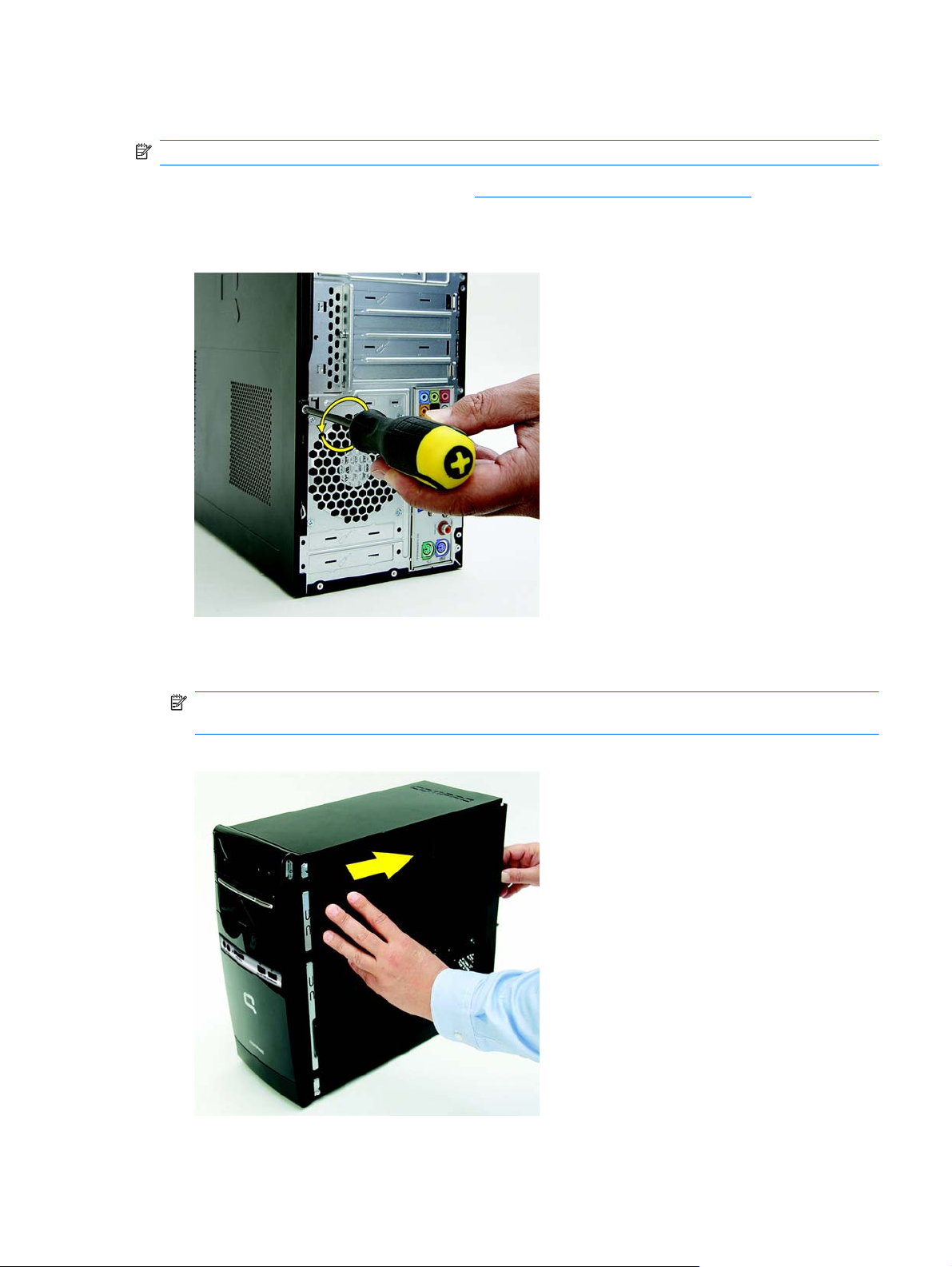
NOTE: Access panel appearance may vary.
1. Prepare the computer for disassembly (Preparation for Disassembly on page 4).
2. Remove the side cover by loosening the screw that connects the cover to the computer.
Figure 2-1 Removing the Computer Access Panel
3. Grasp the handle on the side cover and pull towards the back of the computer. Slide the cover
about 2.4 cm (1 inch) to remove it.
NOTE: You may want to lay the computer on its side to install internal parts. Be sure the side
with the access panel is facing up.
Figure 2-2 Removing the Computer Access Panel
Access Panel
5
Page 14
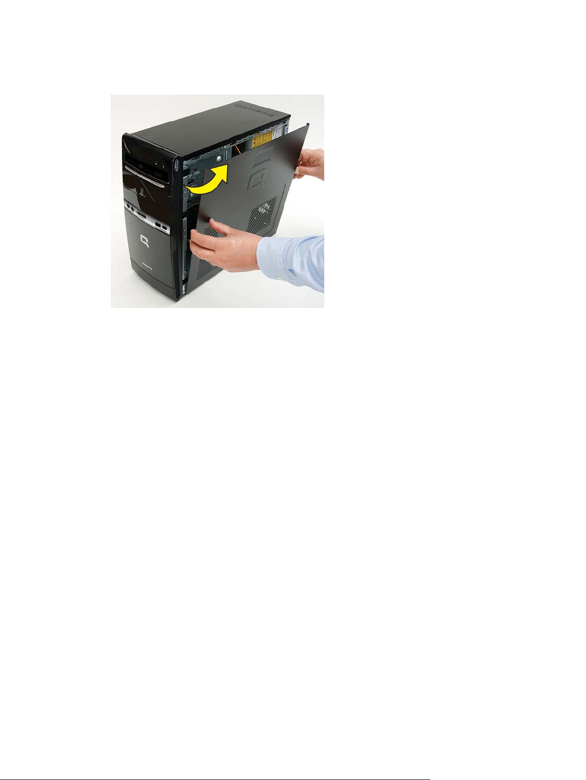
4. Remove the side panel by lifting it away from the computer.
Figure 2-3 Removing the Computer Access Panel
To replace the access panel, reverse the removal steps.
6 Chapter 2 Removal and Replacement Procedures Microtower (MT) Chassis
Page 15
Front Bezel
NOTE: Front bezel appearance may vary.
1. Prepare the computer for disassembly (Preparation for Disassembly on page 4).
2. Remove the access panel (
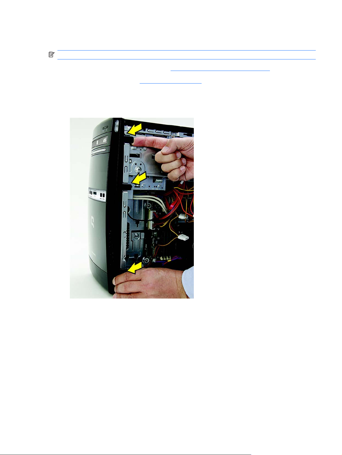
3. Pull each of the three side tabs that secure the front bezel to the computer, to release the front
bezel.
Figure 2-4 Removing the Front Bezel
Access Panel on page 5).
Front Bezel
7
Page 16
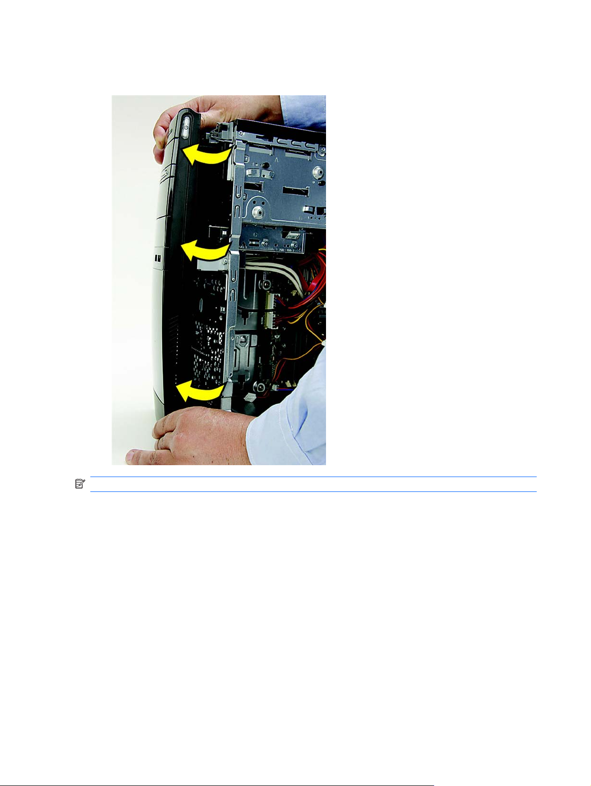
4. Swing the front bezel out to remove from the computer.
Figure 2-5 Removing the Front Bezel
NOTE: The appearance of the front bezel may vary.
To reinstall the front bezel, reverse the removal procedure.
8 Chapter 2 Removal and Replacement Procedures Microtower (MT) Chassis
Page 17

Memory
The computer comes with double data rate 3 synchronous dynamic random access memory
(DDR3-SDRAM) dual inline memory modules (DIMMs).
DDR3-SDRAM DIMMs
The memory sockets on the system board can be populated with up to two industry-standard
DIMMs. These memory sockets are populated with at least one preinstalled DIMM. To achieve the
maximum memory support, you can populate the system board with up to 4 GB of memory
configured in a high-performing dual channel mode.
For proper system operation, the DDR3-SDRAM DIMMs must be:
industry-standard 240-pin
●
unbuffered PC3-10600, 1333 MHz-compliant
●
1.5 volt DDR3-SDRAM DIMMs
●
The DDR3-SDRAM DIMMs must also:
support CAS latency 9 DDR3 1333 Mhz (9-9-9 timing)
●
contain the mandatory JEDEC SPD information
●
In addition, the computer supports:
512Mbit, 1Gbit, and 2Gbit non-ECC memory technologies
●
single-sided and double-sided DIMMs
●
DIMMs constructed with x8 and x16 DDR devices; DIMMs constructed with x4 SDRAM are not
●
supported
NOTE: The system will not operate properly if you install unsupported DIMMs.
Memory
9
Page 18
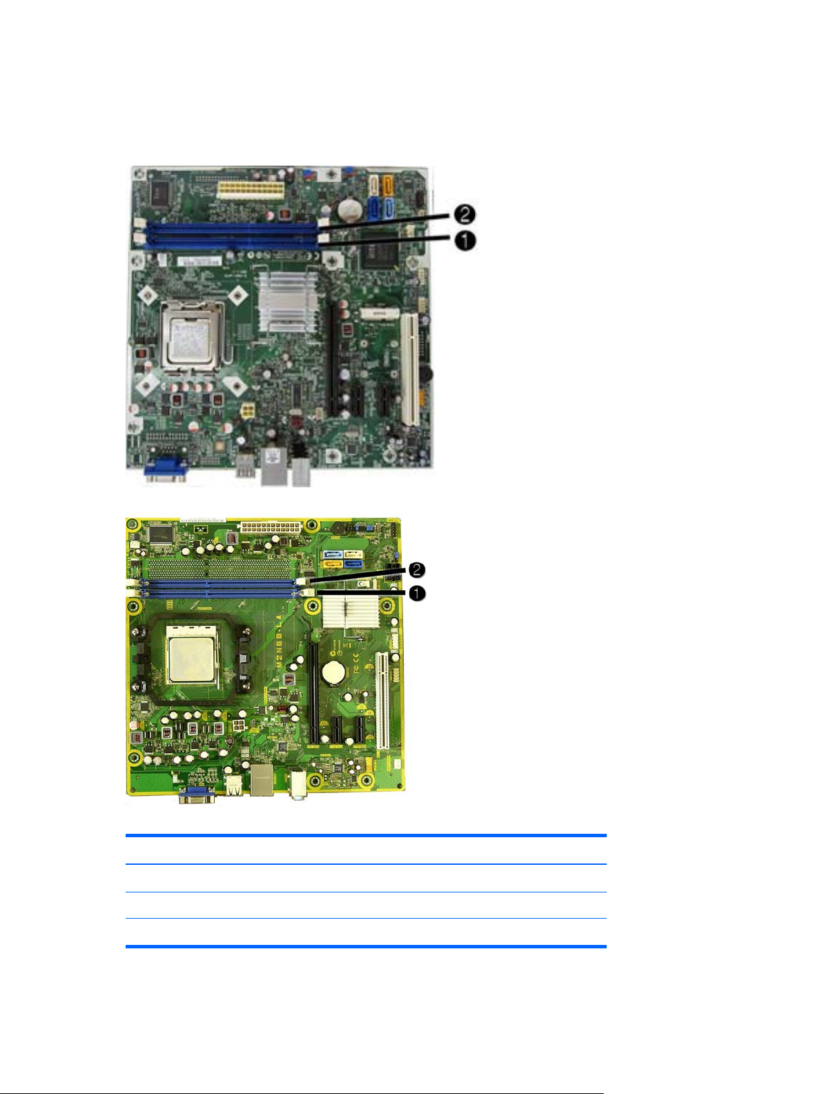
Populating DIMM Sockets
There are two DIMM sockets on the system board.
Figure 2-6 DIMM Socket Locations — 500B/510B
Figure 2-7 DIMM Socket Locations — 505B/515B
Table 2-1 DIMM Socket Locations
Item Description Socket Color
1 DIMM1 socket, Channel A (populate first) Blue
2 DIMM2 socket, Channel A Blue
NOTE: A DIMM must occupy the DIMM1 socket.
10 Chapter 2 Removal and Replacement Procedures Microtower (MT) Chassis
Page 19
Installing Memory Modules
CAUTION: You must disconnect the power cord and wait approximately 30 seconds for the power
to drain before adding or removing memory modules. Regardless of the power-on state, voltage is
always supplied to the memory modules as long as the computer is plugged into an active AC outlet.
Adding or removing memory modules while voltage is present may cause irreparable damage to the
memory modules or system board.
The memory module sockets have gold-plated metal contacts. When upgrading the memory, it is
important to use memory modules with gold-plated metal contacts to prevent corrosion and/or
oxidation resulting from having incompatible metals in contact with each other.
Static electricity can damage the electronic components of the computer or optional cards. Before
beginning these procedures, ensure that you are discharged of static electricity by briefly touching a
grounded metal object.
When handling a memory module, be careful not to touch any of the contacts. Doing so may damage
the module.
1. Prepare the computer for disassembly (Preparation for Disassembly on page 4).
2. Remove the access panel (
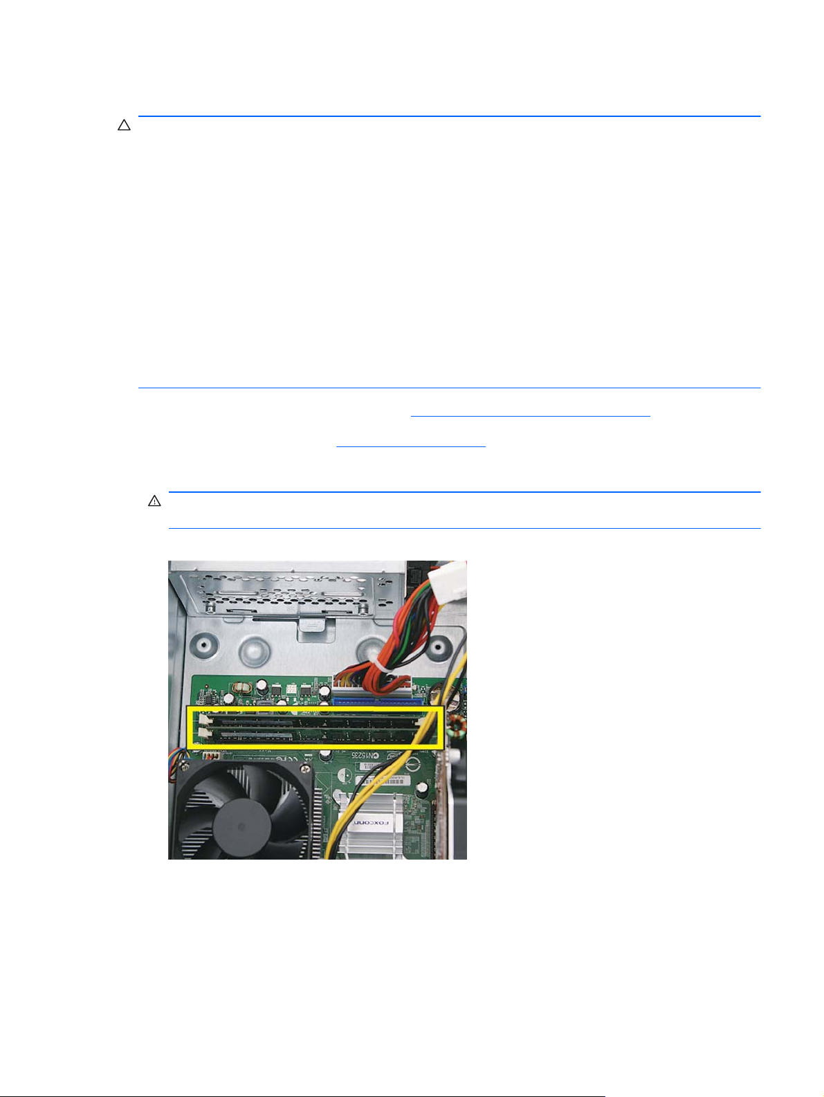
3. Locate the memory module sockets on the system board (500B shown).
WARNING! To reduce risk of personal injury from hot surfaces, allow the internal system
components to cool before touching.
Figure 2-8 DIMM locations (500B shown)
Access Panel on page 5).
Memory
11
Page 20
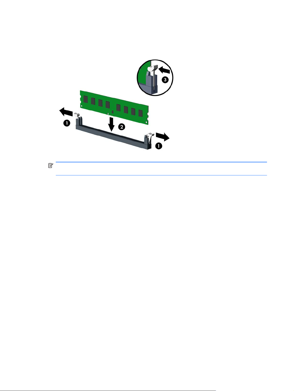
4. Open both latches of the memory module socket (1), and insert the memory module into the
socket (2).
Figure 2-9 Installing a DIMM
NOTE: A memory module can be installed in only one way. Match the notch on the module
with the tab on the memory socket.
5. Push the DIMM module down firmly into the socket, ensuring that the module is fully inserted
and properly seated. The DIMM must be pushed all the way down into the socket and sit evenly
in the socket to avoid memory corruption. Make sure the latches are in the closed position (3).
6. Repeat steps 4 and 5 to install any additional modules.
7. Replace the computer access panel.
8. Reconnect the power cord and any external devices, then turn on the computer. The computer
should automatically recognize the additional memory when you turn on the computer.
9. Lock any security devices that were disengaged when the access panel was removed.
12 Chapter 2 Removal and Replacement Procedures Microtower (MT) Chassis
Page 21
Expansion Cards
The computer has one PCI expansion slot, two PCI Express x1 expansion slots, and one PCI
Express x16 expansion slot. The expansion slots accommodate full-height or half-height expansion
cards.
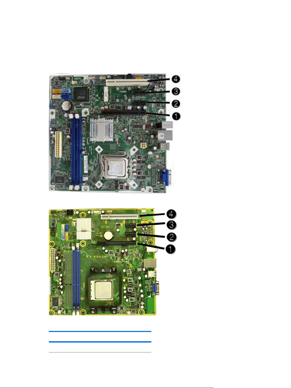
Figure 2-10 Expansion Slot Locations — 500B/510B
Figure 2-11 Expansion Slot Locations — 505B/515B
Table 2-2 Expansion Slot Locations
Item Description
1 PCI Express x16 expansion slot
Expansion Cards
13
Page 22
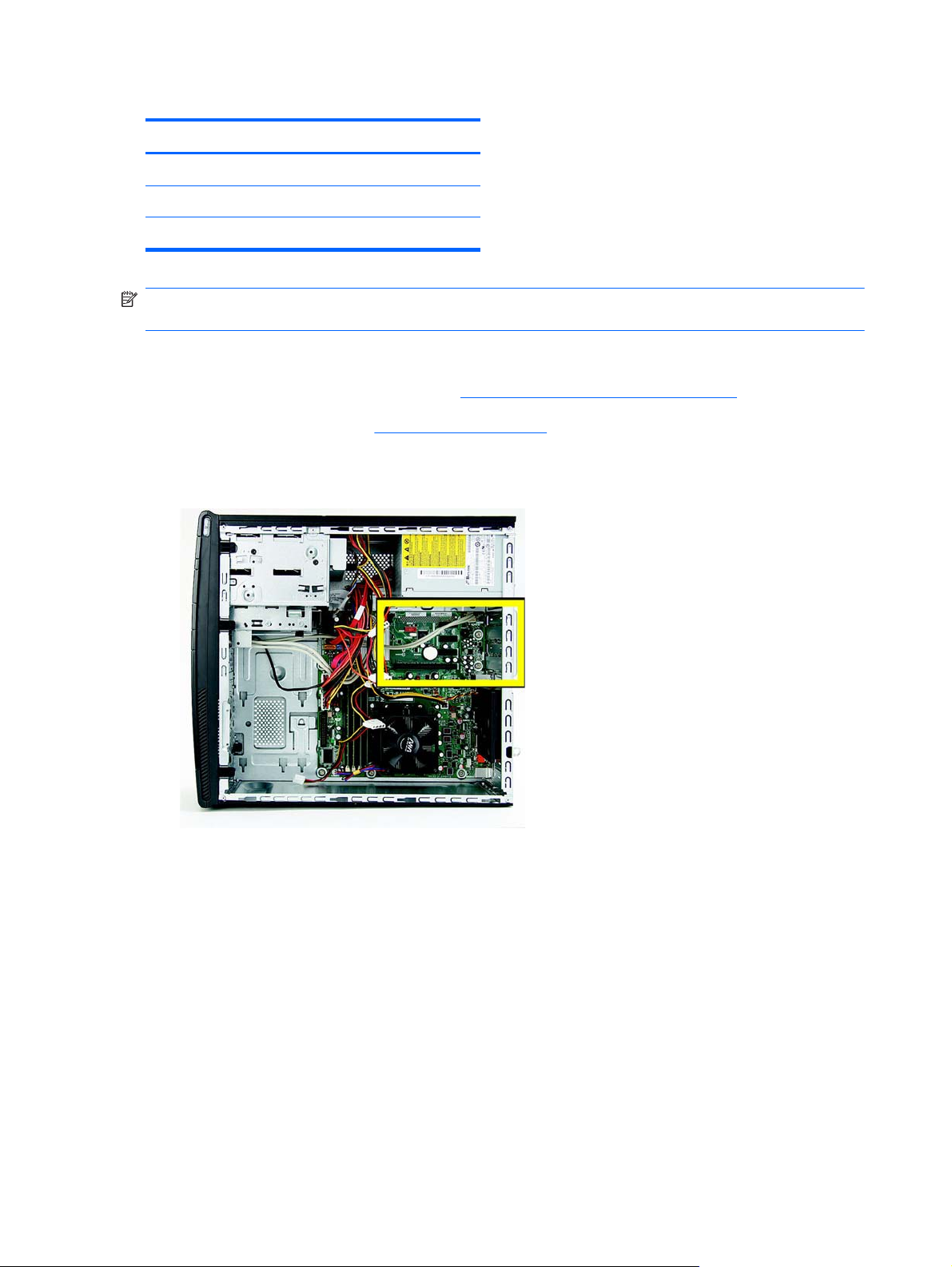
Table 2-2 Expansion Slot Locations (continued)
Item Description
2 PCI Express x1 expansion slot
3 PCI Express x1 expansion slot
4 PCI expansion slot
NOTE: You can install a PCI Express x1, x4, x8, or x16 expansion card in the PCI Express x16
expansion slot.
To remove, replace, or add an expansion card:
1. Prepare the computer for disassembly (
2. Remove the access panel (
Access Panel on page 5).
Preparation for Disassembly on page 4).
3. Locate the add-in cards at the back of the computer.
Figure 2-12 Locating the expansion card slots
14 Chapter 2 Removal and Replacement Procedures Microtower (MT) Chassis
Page 23
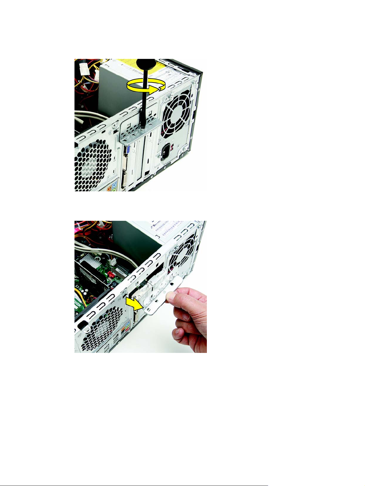
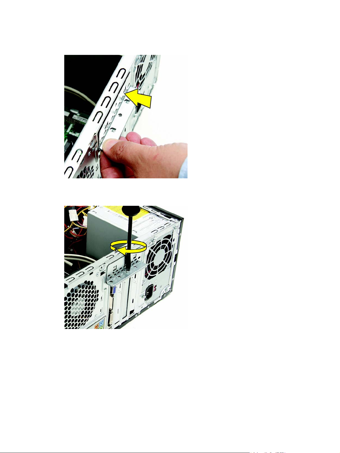
4. On the back of the computer, remove the screw from the bracket cover for the add-in cards.
Figure 2-13 Opening the slot cover lock
5. Remove the bracket cover.
Figure 2-14 Removing the bracket cover
Expansion Cards
15
Page 24
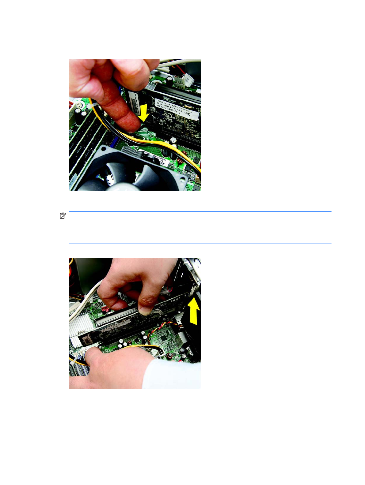
6. If you are removing a graphics card, press on the latch to release it.
Figure 2-15 Press the latch to release the graphics card
7. Remove the graphics card from the card slot.
NOTE: If you are removing a PCI Express x16 card, pull the retention arm on the back of the
expansion socket away from the card and carefully rock the card back and forth until the
connectors pull free from the socket. Be sure not to scrape the card against the other
components.
Figure 2-16 Removing the graphics card from the slot
16 Chapter 2 Removal and Replacement Procedures Microtower (MT) Chassis
Page 25
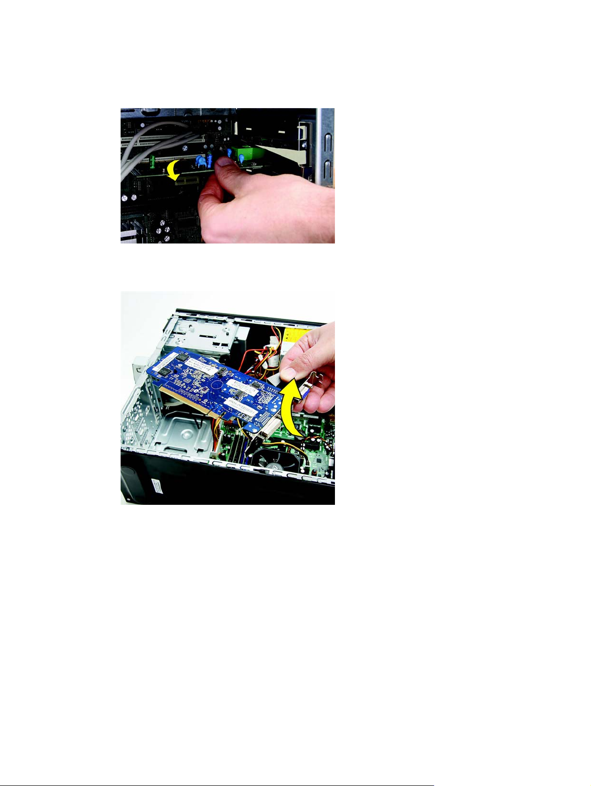
8. For other add-in cards, move the card back and forth gently to free it from the card slot in the
computer.
Figure 2-17 Rocking the card to Remove
9. Lift the card out of the computer.
Figure 2-18 Lifting the card from the computer
Expansion Cards
17
Page 26
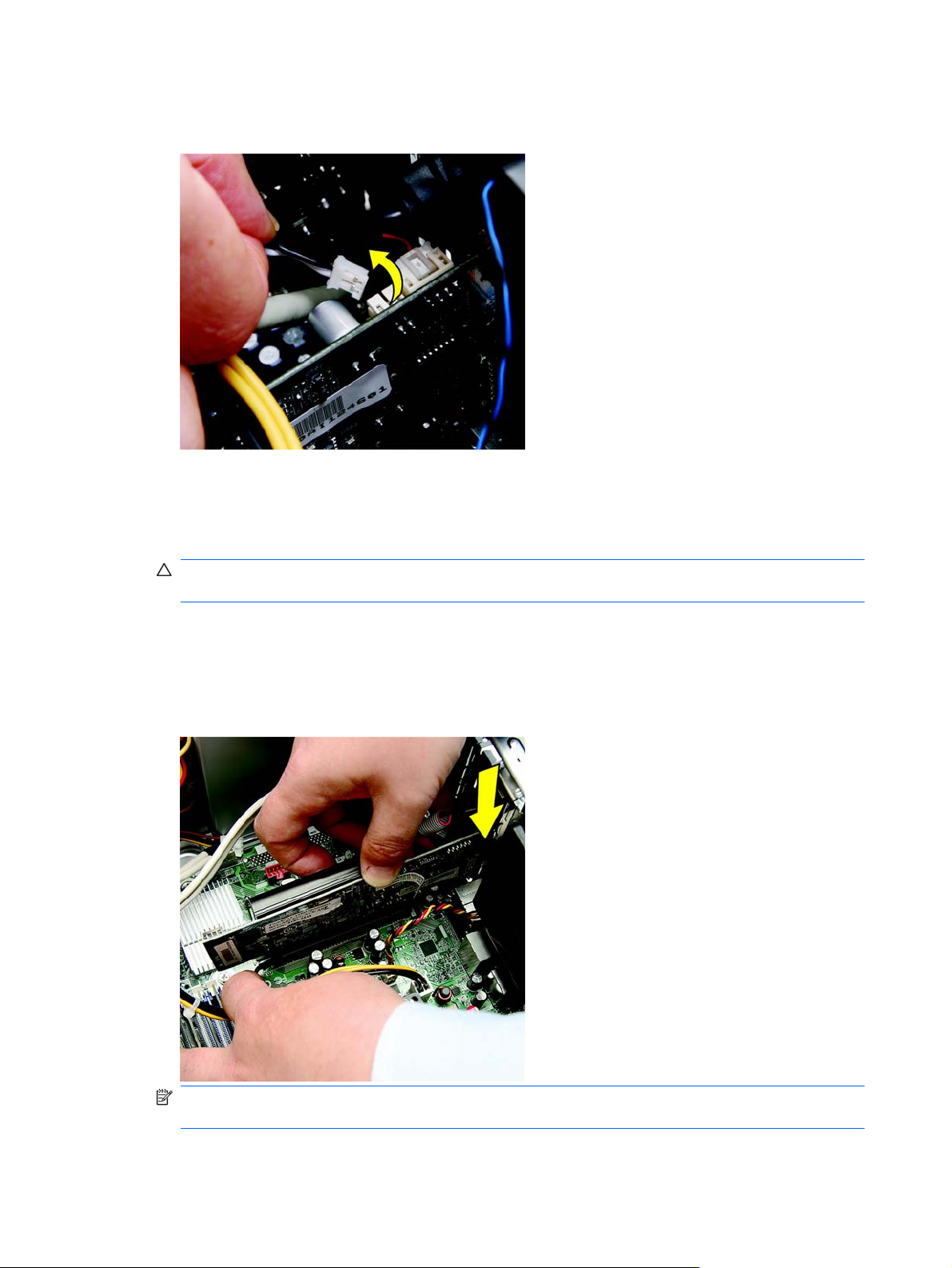
10. If present, remove any cables connected to the add-in card.
Figure 2-19 Removing cables from the card
11. Store the removed card in anti-static packaging.
12. If you are not installing a new expansion card, install an expansion slot cover to close the open
slot.
CAUTION: After removing an expansion card, you must replace it with a new card or
expansion slot cover for proper cooling of internal components during operation.
13. To install a new expansion card, hold the card just above the expansion socket on the system
board then move the card toward the rear of the chassis so that the bottom of the bracket on the
card slides into the small slot on the chassis. Press the card straight down into the expansion
socket on the system board.
Figure 2-20 Installing an expansion card
NOTE: When installing an expansion card, press firmly on the card so that the whole
connector seats properly in the expansion card slot.
18 Chapter 2 Removal and Replacement Procedures Microtower (MT) Chassis
Page 27
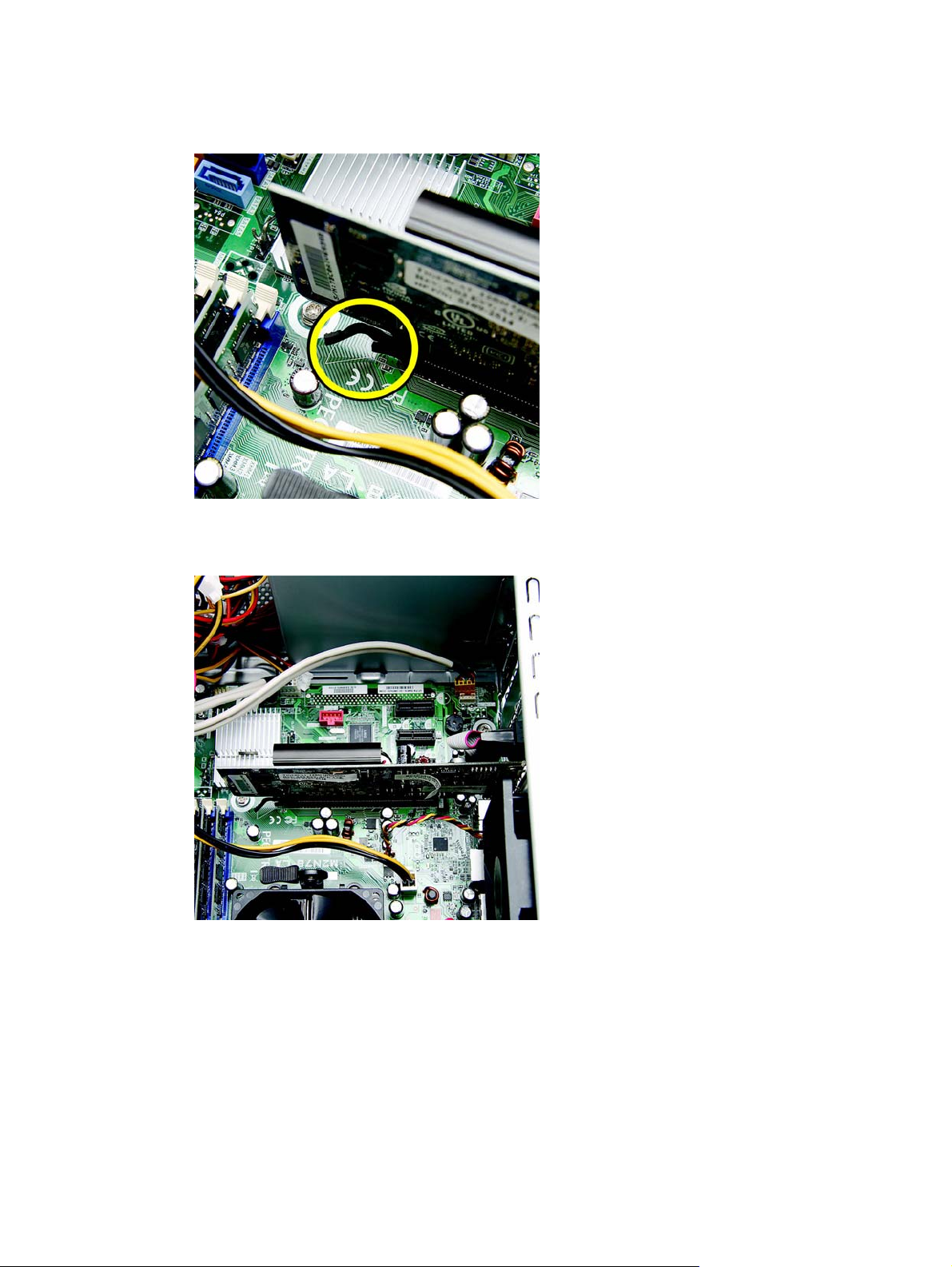
14. If you are replacing a graphics card, verify that the latch in the computer snaps back into place.
Figure 2-21 Replacing a graphics card
15. Press straight down until the card is fully seated in the card slot.
Figure 2-22 Seating the card
Expansion Cards
19
Page 28
16. Replace the bracket cover on the back of the computer.
Figure 2-23 Replacing the bracket cover
17. Replace the screw to secure the bracket to the back of the computer.
Figure 2-24 Replacing the bracket screw
18. Connect external cables to the installed card, if needed. Connect internal cables to the system
board, if needed.
19. Reconfigure the computer, if necessary. Refer to the Computer Setup (F10) Utility Guide for
instructions on using Computer Setup.
20 Chapter 2 Removal and Replacement Procedures Microtower (MT) Chassis
Page 29

Cable Management
Always follow good cable management practices when working inside the computer.
Keep cables away from major heat sources like the heatsink.
●
Do not jam cables on top of expansion cards or memory modules. Printed circuit cards like these
●
are not designed to take excessive pressure on them.
Some flat ribbon cables come prefolded. Never change the folds on these cables.
●
Never bend a SATA data cable tighter than a 30 mm (1.18 in) radius.
●
Never crease a SATA data cable.
●
Do not rely on components like the drive cage, power supply, or computer cover to push cables
●
down into the chassis. Always position the cables to lay properly by themselves.
When removing the power supply power cable from the connector on the system board, always follow
these steps:
1. Squeeze on the top of the retaining latch attached to the cable end of the connector (1).
2. Grasp the cable end of the connector and pull it straight up (2).
CAUTION: Always pull the connector - NEVER pull on the cable. Pulling on the cable could
damage the cable and result in a failed power supply.
Cable Connections
System board connectors are color-coded to make it easier to find the proper connection.
Table 2-3 Cable connections — 500B/510B
Connector Name Connector Color Description
ATX_POWER white power supply, 24-pin
ATX_12V white power supply, 4-pin
SYS_FAN1 brown chassis fan
CPU_FAN white heat sink fan
F PANEL black front power button/LED
F_USB1 white front I/O USB cable
F_AUDIO yellow front I/O audio
SATA1 dark blue hard drive
SATA2 white optical drive
PCI2 white PCI expansion slot
PCIE1X black PCIe x1 expansion slot
Cable Management
21
Page 30

Table 2-3 Cable connections — 500B/510B (continued)
Connector Name Connector Color Description
PCIE1X1 black PCIe x1 expansion slot
PCIE16X black PCIe x16 expansion slot
Table 2-4 Cable connections — 505B/515B
Connector Name Connector Color Description
ATXPOWER white power supply, 24-pin
ATXCPU white power supply, 4-pin
CHASSIS_FAN1 brown chassis fan
CPU FAN white heat sink fan
F_PANEL black front power button/LED
F_USB2 white front I/O USB cable
F_AUDIO yellow front I/O audio
SATA0 dark blue hard drive
SATA1 white optical drive
PCI1 white PCI expansion slot
PCIE_X1_1 black PCIe x1 expansion slot
PCIE_X1_2 black PCIe x1 expansion slot
PCIE X16 black PCIe x16 expansion slot
22 Chapter 2 Removal and Replacement Procedures Microtower (MT) Chassis
Page 31

Drives
The computer supports one optical drive and one hard drive.
This section describes the procedure for replacing or upgrading the drives. A Torx T-15 screwdriver is
needed to remove and install the guide screws on a drive.
Installing Additional Drives
When installing additional drives, follow these guidelines:
Connect the primary SATA hard drive to the dark blue primary SATA connector on the system
●
board labeled SATA1 for model 500B/510B, SATA0 for model 505B/515B.
Connect the SATA optical drive to the white SATA connector on the system board labeled
●
SATA2 on model 500B/510B, SATA1 for model 505B/515B.
CAUTION: To prevent loss of work and damage to the computer or drive:
If you are inserting or removing a drive, shut down the operating system properly, turn off the
computer, and unplug the power cord. Do not remove a drive while the computer is on or in standby
mode.
Before handling a drive, ensure that you are discharged of static electricity. While handling a drive,
avoid touching the connector.
Handle a drive carefully; do not drop it.
Do not use excessive force when inserting a drive.
Avoid exposing a hard drive to liquids, temperature extremes, or products that have magnetic fields
such as monitors or speakers.
If a drive must be mailed, place the drive in a bubble-pack mailer or other protective packaging and
label the package “Fragile: Handle With Care.”
Drives
23
Page 32

System Board Drive Connections
Refer to the following illustration and table to identify the system board drive connectors.
Figure 2-25 System Board Drive Connections — 500B/510B
Figure 2-26 System Board Drive Connections — 505B/515B
Table 2-5 System Board Drive Connections
No. System Board Label — 500B/510B System Board Label — 505B/515B Color
1 SATA1 SATA0 dark blue
2 SATA2 SATA1 white
24 Chapter 2 Removal and Replacement Procedures Microtower (MT) Chassis
Page 33

Removing an Optical Drive
CAUTION: All removable media should be taken out of a drive before removing the drive from the
computer.
To remove an optical drive:
1. Prepare the computer for disassembly (
2. Remove the access panel (
3. Remove the front bezel (
4. Disconnect the power cable (1) and data cable (2) from the rear of the optical drive.
Figure 2-27 Disconnecting the power and data cables
Access Panel on page 5).
Front Bezel on page 7).
Preparation for Disassembly on page 4).
5. Remove the screws that fasten the disc drive in the computer.
Figure 2-28 Removing the optical drive screws
Drives
25
Page 34

6. Push the drive slightly forward.
Figure 2-29 Push the drive forward
7. Pull the disc drive out through the front of the computer.
Figure 2-30 Pull the drive from the computer
NOTE: To install an optical drive, refer to Replacing an Optical Drive on page 27.
26 Chapter 2 Removal and Replacement Procedures Microtower (MT) Chassis
Page 35

Replacing an Optical Drive
To install an optical drive:
1. Prepare the computer for disassembly (
2. Remove the access panel (
3. Remove the front bezel (
4. If the new drive has screws installed on the sides of the drive, remove the screws before
inserting the drive into the chassis.
5. Push the replacement disc drive partially into the drive bay in the computer.
Figure 2-31 Installing the optical drive
6. Connect the power cable (1) and data cable (2) to the rear of the optical drive.
Access Panel on page 5).
Front Bezel on page 7).
Preparation for Disassembly on page 4).
Figure 2-32 Connecting the power and data cables
Drives
27
Page 36

7. Align the disc drive screw holes with the drive bay holes (marked “2”).
Figure 2-33 Aligning the holes
8. Replace the drive screws.
Figure 2-34 Replacing the screws
9. Replace the front bezel, access panel, and reconnect all cables.
10. Lock any security devices that were disengaged when the access panel was removed.
The system automatically recognizes the drive and reconfigures the computer.
Removing a Hard Drive
NOTE: Before you remove the old hard drive, be sure to back up the data from the old hard drive so
that you can transfer the data to the new hard drive. Also, if you are replacing the primary hard drive,
make sure you have created a Recovery Disc Set to restore the operating system, software drivers,
and any software applications that were preinstalled on the computer. If you do not have this CD set,
select Start > HP Backup and Recovery and create it now.
1. Prepare the computer for disassembly (Preparation for Disassembly on page 4).
2. Remove the access panel (
3. Remove the front bezel (
28 Chapter 2 Removal and Replacement Procedures Microtower (MT) Chassis
Access Panel on page 5).
Front Bezel on page 7).
Page 37

4. Locate the external drive bay at the front of the computer, below the optical drive bays.
Figure 2-35 Locating the hard drive
5. Disconnect the power (1) and data (2) cables by squeezing the latch on the connector and
pulling to remove.
Figure 2-36 Disconnecting the hard drive cables
Drives
29
Page 38

6. Remove the two screws that secure the hard disk drive to the computer.
Figure 2-37 Removing the hard drive screws
7. Pull the hard drive out of the front of the computer.
Figure 2-38 Pulling the hard drive from the computer
NOTE: To install a hard drive, refer to Replacing a Hard Drive on page 31.
30 Chapter 2 Removal and Replacement Procedures Microtower (MT) Chassis
Page 39

Replacing a Hard Drive
1. Follow the steps in Removing a Hard Drive on page 28 to remove the hard drive.
2. Slide the replacement hard disk drive into the bay.
NOTE: If you are replacing an old drive with a new drive, use the four retainer screws from the
old drive to install the new drive.
Figure 2-39 Installing the hard drive
3. Align the screw holes on the side of the hard drive with the holes marked “HDD” on the bay.
Figure 2-40 Align the screw holes
CAUTION: Never crease or bend a SATA data cable tighter than a 30 mm (1.18 in) radius. A
sharp bend can break the internal wires.
Drives
31
Page 40

4. Attach the two screws to secure the hard disk drive to the bay.
Figure 2-41 Replacing the screws that secure the hard drive
5. Attach the power and data connectors to the back of the drive.
Figure 2-42 Attaching the connectors
6. Replace the front bezel, computer access panel, and all cables.
7. Lock any security devices that were disengaged when the access panel was removed.
32 Chapter 2 Removal and Replacement Procedures Microtower (MT) Chassis
Page 41

Front I/O and USB Panel Housing Assembly
1. Prepare the computer for disassembly (Preparation for Disassembly on page 4).
2. Remove the access panel (
3. Lay the computer on its side with the front facing toward you.
4. Remove the front bezel (
5. Unplug the four cables that connect the assembly to the system board.
6. Remove the screw (1) that secures the housing to the chassis, slide the housing up (2), and then
pull the assembly away from the chassis while guiding the cables through the hole in the
chassis.
Figure 2-43 Removing the front I/O assembly
Access Panel on page 5)
Front Bezel on page 7).
To install the housing assembly, reverse the removal procedures.
Front I/O and USB Panel Housing Assembly
33
Page 42

Power Switch/LED Assembly
1. Prepare the computer for disassembly (Preparation for Disassembly on page 4).
2. Remove the access panel (
3. Lay the computer on its side with the front facing toward you.
4. Remove the front bezel (
5. Remove the optical drive (
6. Disconnect the braided cables from the system board.
7. Remove the cable from the clips in the optical drive cage.
8. Press the tabs near the bottom on both sides of the switch holder (1) to disengage it from the
chassis, rotate the bottom of the switch upward (2), and then pull it away from the chassis while
guiding the wires through the hole in the chassis.
Figure 2-44 Removing the power switch
Access Panel on page 5).
Front Bezel on page 7).
Removing an Optical Drive on page 25).
To install the power switch/LED assembly, reverse the removal procedures.
34 Chapter 2 Removal and Replacement Procedures Microtower (MT) Chassis
Page 43

System Fan
1. Prepare the computer for disassembly (Preparation for Disassembly on page 4).
2. Remove the access panel (
3. Lay the computer on its side with the rear facing toward you.
4. Disconnect the cable that connects the system fan to the system board.
5. Remove the four Phillips screws that secure the fan to the chassis, rotate the top of the fan
forward, and then remove the fan from the chassis.
Figure 2-45 Removing the system fan
Access Panel on page 5).
To install the fan, reverse the removal procedures.
System Fan
35
Page 44

Heat sink assembly (Intel) — Model 500B/510B
NOTE: Heat sink appearance may vary.
1. Prepare the computer for disassembly (Preparation for Disassembly on page 4).
2. Remove the access panel (
3. Lay the computer on its side with the rear facing toward you.
4. Disconnect the heat sink fan control cable from the system board (1).
5. Remove the four torx screws (1) that secure the heat sink to the system board.
Figure 2-46 Removing the heat sink
Access Panel on page 5).
6. Lift the heat sink from the processor and set it on its side to keep from contaminating the work
area with thermal grease.
CAUTION: Heat sink retaining screws should be tightened in diagonally opposite pairs (as in an X)
to evenly seat the heat sink to the processor. This is especially important as the pins on the socket
are very fragile and any damage to them may require replacing the system board.
When reinstalling an existing heat sink, make sure that its bottom has been cleaned with an alcohol
wipe and fresh thermal grease has been applied to the top of the processor. New heatsinks come
from the factory with fresh thermal grease already applied.
36 Chapter 2 Removal and Replacement Procedures Microtower (MT) Chassis
Page 45

Heat sink assembly (AMD) — Model 505B/515B
1. Prepare the computer for disassembly (Preparation for Disassembly on page 4).
2. Remove the access panel (
3. Lay the computer on its side with the rear facing toward you.
4. Disconnect the heat sink fan control cable from the system board.
5. Lift the lever (1) that secures the heat sink latch to the heat sink bracket attached to the system
board.
6. After loosening the lever, press downward on the lever to release the square clip (2) from the tab
on the heat sink bracket.
7. Use the lever to maneuver the square clip on the opposite side on the heat sink (3) free from the
tab on the heat sink bracket.
8. Lift the heat sink from the processor and set it on its side to keep from contaminating the work
area with thermal grease.
Figure 2-47 Removing the heat sink
Access Panel on page 5).
CAUTION: Heat sink retaining screws should be tightened in diagonally opposite pairs (as in an X)
to evenly seat the heat sink to the processor. This is especially important as the pins on the socket
are very fragile and any damage to them may require replacing the system board.
When reinstalling an existing heat sink, make sure that its bottom has been cleaned with an alcohol
wipe and fresh thermal grease has been applied to the top of the processor. New heatsinks come
from the factory with fresh thermal grease already applied.
Heat sink assembly (AMD) — Model 505B/515B
37
Page 46

Processor (Intel) — Model 500B/510B
1. Prepare the computer for disassembly (Preparation for Disassembly on page 4).
2. Remove the access panel (
3. Lay the computer on its side with the rear facing toward you.
4. Disconnect the heatsink control cable from the system board and remove the heatsink
assembly (Intel) — Model 500B/510B on page 36).
5. Rotate the locking lever to its full open position (1).
6. Raise and rotate the microprocessor retainer to its full open position (2)
7. Carefully lift the processor from the socket (3).
CAUTION: Do NOT handle the pins in the processor socket. These pins are very fragile and
handling them could cause irreparable damage. Once pins are damaged it may be necessary to
replace the system board.
CAUTION: The heatsink must be installed within 24 hours of installing the processor to prevent
damage to the processor’s solder connections.
Figure 2-48 Removing an Intel processor
Access Panel on page 5).
Heat sink
To install a new processor:
1. Place the processor in its socket and close the retainer.
2. Secure the locking lever.
If reusing the existing heat sink, go to step 3.
If using a new heat sink, go to step 6.
3. If reusing the existing heat sink, clean the bottom of the heat sink with the alcohol pad provided
in the spares kit.
38 Chapter 2 Removal and Replacement Procedures Microtower (MT) Chassis
Page 47

4. Apply the thermal grease provided in the spares kit to the top of the processor and install the
heat sink atop the processor.
5. Go to step 7.
6. If using a new heat sink, remove the protective covering from the bottom of the heat sink and
place it in position atop the processor.
7. Secure the heat sink to the system board and system board tray with the 4 captive screws and
attach the heat sink control cable to the system board.
CAUTION: Heat sink retaining screws should be tightened in diagonally opposite pairs (as in
an X) to evenly seat the heat sink on the processor. This is especially important as the pins on
the socket are very fragile and any damage to them may require replacing the system board.
NOTE: After installing a new processor onto the system board, always update the system
ROM to ensure that the latest version of the BIOS is being used on the computer. The latest
system ROM BIOS can be found on the Web at:
http:\\h18000.www1.hp.com/support/files.
Processor (Intel) — Model 500B/510B
39
Page 48

Processor (AMD) — Model 505B/515B
1. Prepare the computer for disassembly (Preparation for Disassembly on page 4).
2. Remove the access panel (
3. Disconnect the heatsink control cable from the system board and remove the heatsink
assembly (AMD) — Model 505B/515B on page 37).
4. Rotate the locking lever to its full open position (1).
5. Carefully lift the processor from the socket (2).
CAUTION: Do NOT handle the pins in the processor socket. These pins are very fragile and
handling them could cause irreparable damage. Once pins are damaged it may be necessary to
replace the system board.
The heat sink must be installed within 24 hours of installing the processor to prevent damage to
the processor’s solder connections.
Figure 2-49 Removing an AMD processor
Access Panel on page 5).
Heat sink
To install a new processor:
1. Place the processor in its socket and close the retainer.
2. Secure the locking lever.
If reusing the existing heat sink, go to step 3.
If using a new heat sink, go to step 5.
3. If reusing the existing heat sink, apply the thermal grease provided in the spares kit to the top of
the processor.
4. Clean the bottom of the heat sink with the provided alcohol pad and place it atop the processor.
40 Chapter 2 Removal and Replacement Procedures Microtower (MT) Chassis
Page 49

5. If using a new heat sink, remove the protective covering from the bottom of the heat sink and
place it in position atop the processor.
6. Secure the heat sink to the system board and system board tray with the four captive screws
and attach the heat sink control cable to the system board.
CAUTION: heat sink retaining screws should be tightened in diagonally opposite pairs (as in
an X) to evenly seat the heat sink on the processor. This is especially important as the pins on
the socket are very fragile and any damage to them may require replacing the system board.
NOTE: After installing a new processor onto the system board, always update the system ROM to
ensure that the latest version of the BIOS is being used on the computer. The latest system BIOS can
be found on the Web at:
Power Supply
NOTE: Power supply appearance may vary.
WARNING! Voltage is always present on the system board when the computer is plugged into an
active AC outlet. To avoid possible personal injury and damage to the equipment the power cord
should be disconnected from the computer and/or the AC outlet before opening the computer.
NOTE: When installing a new power supply, be sure to set the red switch to the setting (230 V or
115 V) appropriate for the country in which the computer is used. Spare power supplies normally
arrive set for 230 V.
http://h18000.www1.hp.com/support/files.
1. Prepare the computer for disassembly (Preparation for Disassembly on page 4).
2. Remove the access panel (
3. Lay the computer on its side with the rear facing toward you.
4. Disconnect all power cables from the mass storage devices and from the system board.
5. Place the computer on its side.
Access Panel on page 5).
Power Supply
41
Page 50

6. Locate the power supply at the top of the computer.
Figure 2-50 Locating the power supply
NOTE: Noting the location, type and orientation of the power connectors is extremely
important. Failure to correctly restore all power connectors appropriately will prevent the
computer or components from working successfully.
NOTE: The location of the power connectors on the motherboard may vary from the ones
shown below.
7. Trace the power supply cables to the system components:
Optical disc drives (A)
●
Hard disk drives (B)
●
Motherboard main power (C)
●
Motherboard fan (D)
●
Figure 2-51 Power supply connections
42 Chapter 2 Removal and Replacement Procedures Microtower (MT) Chassis
Page 51

8. Disconnect the power cable from the optical disc and hard disk drives by squeezing the latch (1)
on the connectors and pulling to remove.
Figure 2-52 Disconnecting the power cable
Power Supply
43
Page 52

9. The motherboard power connector has a latch that must be pressed to detach the connector
from the motherboard.
Figure 2-53 Disconnecting the main system board power connector
Some connectors may have latches that must be pressed to remove them.
Figure 2-54 Connector Latches
44 Chapter 2 Removal and Replacement Procedures Microtower (MT) Chassis
Page 53

10. Disconnect all other power connectors from the motherboard.
Figure 2-55 Disconnecting power connectors
11. Remove the four screws that connect the power supply to the computer. The images below
illustrate possible power supply screw locations.
Figure 2-56 Removing the power supply screws
Power Supply
45
Page 54

12. Use a screwdriver to press the latch at the bottom of the power supply to release it.
Figure 2-57 Pressing the power supply latch
13. Pull the power supply back and tilt it out of the computer.
Figure 2-58 Removing the power supply from the computer
To install the power supply, reverse the removal procedure. Note that there is a latch, a guide, and a
ledge on the computer that help secure the power supply.
46 Chapter 2 Removal and Replacement Procedures Microtower (MT) Chassis
Page 55

Figure 2-59 Power supply securing features
System Board
When replacing the system board, be sure that the following components are removed from the
defective system board and installed on the replacement system board:
Memory modules
●
Processor
●
Expansion modules
●
To remove the system board:
1. Prepare the computer for disassembly (
2. Remove the access panel (
3. Lay the computer on its side with the rear facing toward you.
4. Remove the front bezel (
5. Remove an expansion cards (
6. Disconnect the power, and data cables from the back of all installed drives.
7. Disconnect all cables from the system board.
8. Remove the eight screws that secure the system board to the chassis.
Access Panel on page 5).
Front Bezel on page 7).
Expansion Cards on page 13).
Preparation for Disassembly on page 4).
System Board
47
Page 56

9. Slide the system board toward the front of the chassis, and then lift it up and out of the chassis.
NOTE: The system board in the computer may look slightly different from the one shown here.
Figure 2-60 Removing the system board — model 500B shown
To install the system board, reverse the removal procedure.
NOTE: When replacing the system board, you must also change the chassis serial number in the
BIOS.
NOTE: After installing a new system board, always update the system ROM to ensure that the
latest version of the BIOS is being used on the computer. The latest system ROM BIOS can be found
http:\\h18000.www1.hp.com/support/files.
at:
Battery
The battery that comes with your computer provides power to the real-time clock and has a
lifetime of about three years. When replacing the battery, use a battery equivalent to the battery
originally installed on the computer. The computer comes with a 3-volt lithium coin cell battery.
NOTE: The lifetime of the lithium battery can be extended by plugging the computer into a live AC
wall socket. The lithium battery is only used when the computer is NOT connected to AC power.
48 Chapter 2 Removal and Replacement Procedures Microtower (MT) Chassis
Page 57

WARNING! This computer contains an internal lithium manganese dioxide battery. There is a risk of
fire and burns if the battery is not handled properly. To reduce the risk of personal injury:
Do not attempt to recharge the battery.
Do not expose to temperatures higher than 60°C (140°F)
Do not disassemble, crush, puncture, short external contacts, or dispose of in fire or water.
Replace the battery only with the HP/Compaq spare designated for this product.
CAUTION: Before replacing the battery, it is important to back up the computer CMOS settings.
When the battery is removed or replaced, the CMOS settings will be cleared. Refer to the
Troubleshooting Guide for information on backing up the CMOS settings.
NOTE: Batteries, battery packs, and accumulators should not be disposed of together with the
general household waste. In order to forward them to recycling or proper disposal, please use the
public collection system or return them to HP, its authorized partners, or its agents.
CAUTION: Static electricity can damage the electronic components of the computer or optional
equipment. Before beginning these procedures, ensure that you are discharged of static electricity by
briefly touching a grounded metal object.
1. Prepare the computer for disassembly (Preparation for Disassembly on page 4).
2. Remove the access panel (
NOTE: It may be necessary to remove an expansion card to gain access to the battery.
3. Locate the battery and battery holder on the system board.
Type 1 Battery Holder
1. Lift the battery out of its holder.
2. Slide the replacement battery into position, positive side up.
Access Panel on page 5).
3. The battery holder automatically secures the battery in the proper position.
4. Replace the computer access panel.
Battery
49
Page 58

5. Plug in the computer and turn on power to the computer.
6. Reset the date and time, your passwords, and any special system setups, using Computer
Setup. Refer to the Computer Setup (F10) Utility Guide.
Type 2 Battery Holder
1. To release the battery from its holder, squeeze the metal clamp that extends above one edge of
the battery. When the battery pops up, lift it out (1).
2. To insert the new battery, slide one edge of the replacement battery under the holder’s lip with
the positive side up (2). Push the other edge down until the clamp snaps over the other edge of
the battery.
3. Replace the computer access panel.
4. Plug in the computer and turn on power to the computer.
5. Reset the date and time, your passwords, and any special system setups, using Computer
Setup. Refer to the Computer Setup (F10) Utility Guide.
Type 3 Battery Holder
1. Pull back on the clip (1) that holds the battery in place, then remove the battery (2).
50 Chapter 2 Removal and Replacement Procedures Microtower (MT) Chassis
Page 59

2. Insert the new battery and position the clip back in place.
3. Replace the computer access panel.
4. Plug in the computer and turn on power to the computer.
5. Reset the date and time, your passwords, and any special system setups, using Computer
Setup. Refer to the Computer Setup (F10) Utility Guide.
Battery
51
Page 60

A Computer (F10) Setup
Model 500B/510B — Computer Setup (F10) Utilities
Use Computer Setup (F10) Utility to do the following:
Change factory default settings.
●
Set the system date and time.
●
Set, view, change, or verify the system configuration, including settings for graphics, audio,
●
storage, communications, and input devices.
View settings for processor and memory.
●
Modify the boot order of bootable devices such as hard drives, diskette drives, optical drives, or
●
USB flash media devices.
Restrict a device from booting the unit.
●
Run hard drive self-tests.
●
Establish a supervisor password that controls access to Computer Setup (F10) Utility and the
●
settings described in this section.
Enable or disable removable media boot ability.
●
Using Computer Setup (F10) Utilities
Computer Setup can be accessed only by turning the computer on or restarting the system.
To access the Computer Setup Utilities menu, complete the following steps:
1. Turn on or restart the computer.
2. As soon as the computer is turned on, press F10 when the monitor light turns green to enter
Computer Setup.
NOTE: If you do not press F10 at the appropriate time, you must restart the computer and
again press F10 when the monitor light turns green to access the utility.
3. The Computer Setup Utility screen is divided into menu headings and actions.
52 Appendix A Computer (F10) Setup
Page 61

Five menu headings appear on the Computer Setup Utility screen:
Main
●
Advanced
●
Power
●
Boot
●
Exit
●
Use the arrow keys to select the appropriate heading, then press Enter. Use the arrow (up and
down) keys to select the option you want, then press Enter. To return to the previous screen,
press Esc.
CAUTION: Do NOT turn the computer power OFF while the ROM is saving the Computer Setup
(F10) changes because the CMOS could become corrupted. It is safe to turn off the computer only
after exiting the F10 Setup screen.
Computer Setup—Main
NOTE: Support for specific Computer Setup options may vary depending on the hardware
configuration.
Table A-1 Computer Setup—Main
Option Description
System Time Allows you to set system time.
System Date Allows you to set system date.
Language Allows you to select language.
Floppy Diskette A: Allows you to set drive A to:
Disabled
●
1.44 MB 3.5”
●
Not Installed
●
Model 500B/510B — Computer Setup (F10) Utilities
53
Page 62

Table A-1 Computer Setup—Main (continued)
1st Drive
2nd Drive
3rd Drive
4th Drive
System Information (view only)
For each, allows you to:
Port Configuration - set the ability to configure ports to:
●
◦
◦
(view only)
●
◦
◦
Smart Support - run HDD self-test for selected channel:
●
◦
◦
◦
Installed Memory
●
Memory Bank 1
●
Memory Bank 2
●
Enabled
Disabled
Capacity (Size - HDD only)
Transfer Mode
SMART Status Check
SMART Short Self-Test
SMART Extended Self-Test
BIOS Revision
●
Core Version
●
Model Number
●
Serial Number
●
Product Number
●
Asset Tag
●
Computer Setup—Advanced
NOTE: Support for specific Computer Setup options may vary depending on the hardware
configuration.
WARNING! Setting items on this menu to incorrect values may cause your system to malfunction.
Table A-2 Computer Setup—Advanced
Option Description
CPU Type (view only)
CPU Speed (view only)
Cache RAM (view only)
54 Appendix A Computer (F10) Setup
Page 63

Table A-2 Computer Setup—Advanced (continued)
Primary Video Adapter Allows you to select the boot display device when more than 2 video options are offered by the
system:
PCI
●
PCI-Ex16
●
Onboard Video
Memory Size
SATA Controller Allows you to disable/enable the SATA Controller.
USB Ports Allows you to disable/enable the USB ports.
Onboard LAN Allows you to disable/enable onboard LAN controller.
Onboard LAN Boot
ROM
Supervisor Password Shows whether the supervisor password is enabled or disabled (view only).
User Password Shows whether the user password is enabled or disabled (view only).
Change Supervisor
Password
Onboard Audio Allows you to set the onboard audio to:
32 MB
●
64 MB
●
128 MB
●
Allows you to disable/enable the boot ROM of the onboard LAN chip.
Allows you to change the supervisor password.
Auto
●
Disabled
●
Enabled
●
Microphone Input Allows you to set disable/enable microphone input.
Computer Setup—Power
NOTE: Support for specific Computer Setup options may vary depending on the hardware
configuration.
Table A-3 Computer Setup—Power
Option Description
After AC Power
Failure
Allows you to select system restart behavior after power loss:
●
●
●
Stay Off
Power On
Auto
Model 500B/510B — Computer Setup (F10) Utilities
55
Page 64

Table A-3 Computer Setup—Power (continued)
XD Disables/enables XD (eXecute Disable) bit.
NOTE: The XD bit is a technology used in to separate areas of memory for use by either storage
of processor instructions or code or for storage of data. Memory designated with the NX attribute
may only be used for storing data. Processor instructions should not reside and cannot be
executed there. This technology is used to prevent buffer overflow attacks – malicious software
that takes over computers by inserting code into another program's data storage area and running
that code.
S5 Maximum Power
Savings
Disables/enables the S5 power setting. Enabling this setting enables the EuP Lot6 power
specification of 1 Watt in S5 mode. This setting disable various system board components to
reduce power consumption.
56 Appendix A Computer (F10) Setup
Page 65

Computer Setup—Boot
NOTE: Support for specific Computer Setup options may vary depending on the hardware
configuration.
Table A-4 Computer Setup—Boot
Option Description
Boot-time Diagnostic
Screen
ESC: Boot Menu Enables/disables the ability to press the Esc key to access the boot menu during boot.
F9: Diagnostics Enables/disables the ability to press the F9 key to access the Diagnostics menu during boo.
F10: Setup Enables/disables the ability to press the F10 key to access the Setup menu during boo.
F11: Recovery Enables/disables the ability to press the F11 key to access the recovery menu during boo.
F12: Boot from LAN Enables/disables the ability to press the F12 key to boot from LAN.
Boot Device Priority Allows you to specify which device groups will boot first, second, third, and fourth or to disable any
Disables/enables POST diagnostic messages display.
of the four:
1st Boot Device
●
2nd Boot Device
●
3rd Boot Device
●
4th Boot Device
●
Options for each boot device include:
CD-ROM Group
●
Hard Drive Group
●
CD-ROM Group Boot
Priority
Hard Drive Group
Boot Priority
Floppy Group Boot
Priority
Network Group Boot
Priority
Floppy Group
●
Network Boot Group
NOTE: MS-DOS drive lettering assignments may not apply after a non-MS-DOS operating
system has started.
Specifies boot device priority within CD/DVD drives.
Specifies boot device priority within hard drives.
Specifies boot device priority within removable devices.
Specifies boot device priority within bootable network devices.
Model 500B/510B — Computer Setup (F10) Utilities
57
Page 66

Computer Setup—Exit
NOTE: Support for specific Computer Setup options may vary depending on the hardware
configuration.
Table A-5 Computer Setup—Exit
Option Description
Exit Saving Changes Press Enter to exit saving changes.
Exit Discarding
Changes
Load Setup Defaults Press Enter to load setup defaults.
Discard Changes Press Enter to discard changes.
Save Changes Press Enter to save changes.
Press Enter to exit discarding changes.
Model 505B/515B — Computer Setup (F10) Utilities
Use Computer Setup (F10) Utility to do the following:
Change factory default settings.
●
Set the system date and time.
●
Set, view, change, or verify the system configuration, including settings for graphics, audio,
●
storage, communications, and input devices.
View settings for processor and memory.
●
Modify the boot order of bootable devices such as hard drives, diskette drives, optical drives, or
●
USB flash media devices.
Restrict a device from booting the unit.
●
Run hard drive self-tests.
●
Establish a supervisor password that controls access to Computer Setup (F10) Utility and the
●
settings described in this section.
Enable or disable removable media boot ability.
●
58 Appendix A Computer (F10) Setup
Page 67

Using Computer Setup (F10) Utilities
Computer Setup can be accessed only by turning the computer on or restarting the system.
To access the Computer Setup Utilities menu, complete the following steps:
1. Turn on or restart the computer.
2. As soon as the computer is turned on, press F10 when the monitor light turns green to enter
Computer Setup.
NOTE: If you do not press F10 at the appropriate time, you must restart the computer and
again press F10 when the monitor light turns green to access the utility.
3. The Computer Setup Utility screen is divided into menu headings and actions.
Five menu headings appear on the Computer Setup Utility screen:
Main
●
Advanced
●
Power
●
Boot
●
Exit
●
Use the arrow keys to select the appropriate heading, then press Enter. Use the arrow (up and
down) keys to select the option you want, then press Enter. To return to the previous screen,
press Esc.
CAUTION: Do NOT turn the computer power OFF while the ROM is saving the Computer Setup
(F10) changes because the CMOS could become corrupted. It is safe to turn off the computer only
after exiting the F10 Setup screen.
Computer Setup—Main
NOTE: Support for specific Computer Setup options may vary depending on the hardware
configuration.
Table A-6 Computer Setup—Main
Option Description
System Time Allows you to set system time.
System Date Allows you to set system date.
Language Allows you to select language.
Floppy Diskette A: Allows you to set drive A to:
●
Disabled
1.44 MB 3.5”
●
Not Installed
●
Model 505B/515B — Computer Setup (F10) Utilities
59
Page 68

Table A-6 Computer Setup—Main (continued)
1st Drive
2nd Drive
3rd Drive
4th Drive
System Information (view only)
For each, allows you to:
Port Configuration - set the ability to configure ports to:
●
◦
◦
(view only)
●
◦
◦
Smart Support - run HDD self-test for selected channel:
●
◦
◦
◦
Installed Memory
●
Memory Bank 1
●
Memory Bank 2
●
Enabled
Disabled
Capacity (Size - HDD only)
Transfer Mode
SMART Status Check
SMART Short Self-Test
SMART Extended Self-Test
BIOS Revision
●
Core Version
●
Model Number
●
Product Number
●
Asset Tag (press Enter to change)
●
Computer Setup—Advanced
NOTE: Support for specific Computer Setup options may vary depending on the hardware
configuration.
WARNING! Setting items on this menu to incorrect values may cause your system to malfunction.
Table A-7 Computer Setup—Advanced
Option Description
CPU Type (view only)
CPU Speed (view only)
Cache RAM (L2) (view only)
Cache RAM (L3) (view only)
60 Appendix A Computer (F10) Setup
Page 69

Table A-7 Computer Setup—Advanced (continued)
Primary Video Adapter Allows you to select the boot display device when more than 2 video options are offered by the
system:
PCI
●
PCI-E x1
●
PCI-E x16
●
Onboard
●
Onboard LAN Allows you to disable/enable onboard LAN controller.
Onboard LAN Boot
ROM
Onboard Audio Allows you to set the onboard audio to:
Supervisor Password Shows whether the supervisor password is enabled or disabled (view only).
User Password Allows you to change the user password.
USB Ports Lists USB ports 1-10, what is connected to the port, and allows you to enable/disable each port.
Change Supervisor
Password
Allows you to disable/enable the boot ROM of the onboard LAN chip.
●
●
●
Allows you to change supervisor password.
Computer Setup—Power
NOTE: Support for specific Computer Setup options may vary depending on the hardware
configuration.
Table A-8 Computer Setup—Power
Auto
Disabled
Enabled
Option Description
After AC Power
Failure
NX (No Execute) Disables/enables NX bit.
Virtualization
Technology
Allows you to select system restart behavior after power loss:
Auto
●
Power On
●
Stay Off
●
Allows you to enable/disable Virtualization Technology (VT). VT enables a CPU feature to run
multiple simultaneous virtual machines allowing specialized software to run in full isolation of each
other.
Model 505B/515B — Computer Setup (F10) Utilities
61
Page 70

Table A-8 Computer Setup—Power (continued)
S5 Maximum Power
Savings
WOL in S5 Allows you to view whether WOL is disabled or enabled in S5 (view only).
Disables/enables the S5 power setting. Enabling this setting enables the EuP Lot6 power
specification of 1 Watt in S5 mode. This setting disable various system board components to
reduce power consumption.
62 Appendix A Computer (F10) Setup
Page 71

Computer Setup—Boot
NOTE: Support for specific Computer Setup options may vary depending on the hardware
configuration.
Table A-9 Computer Setup—Boot
Option Description
Boot-time Diagnostic
Screen
Boot Device Priority Allows you to specify which device groups will boot first, second, third, and fourth or to disable any
ESC: Boot Menu Enables/disables the ability to press the Esc key to access the boot menu during boot.
Disables/enables POST diagnostic messages display.
of the four:
1st Boot Device
●
2nd Boot Device
●
3rd Boot Device
●
4th Boot Device
●
Options for each boot device include:
CD-ROM Group
●
Hard Drive Group
●
Floppy Group
●
Network Boot Group
NOTE: MS-DOS drive lettering assignments may not apply after a non-MS-DOS operating
system has started.
F9: Diagnostics Enables/disables the ability to press the F9 key to access the Diagnostics menu during boo.
F10: Setup Enables/disables the ability to press the F10 key to access the Setup menu during boo.
F11: Recovery Enables/disables the ability to press the F11 key to access the recovery menu during boo.
F12: Boot from LAN Enables/disables the ability to press the F12 key to boot from LAN.
Floppy Group Boot
Priority
CD-ROM Group Boot
Priority
Hard Drive Group
Boot Priority
Network Group Boot
Priority
Specifies boot device priority within removable devices.
Specifies boot device priority within CD/DVD drives.
Specifies boot device priority within hard drives.
Specifies boot device priority within bootable network devices.
Model 505B/515B — Computer Setup (F10) Utilities
63
Page 72

Computer Setup—Exit
NOTE: Support for specific Computer Setup options may vary depending on the hardware
configuration.
Table A-10 Computer Setup—Exit
Option Description
Exit Saving Changes Press Enter to exit saving changes.
Exit Discarding
Changes
Load Setup Defaults Press Enter to load setup defaults.
Discard Changes Press Enter to discard changes.
Save Changes Press Enter to save changes.
Press Enter to exit discarding changes.
64 Appendix A Computer (F10) Setup
Page 73

B Diagnostics
Interpreting Diagnostic Beep Codes
The Power-On Self-Test (POST) is a series of diagnostic tests that runs automatically when the
computer is powered on. If the POST detects an error, this causes an audible beep code to sound.
The POST beep codes are not necessarily accompanied by an associated, visble error code or text
message.
The following table shows the POST beep codes, their meanings, and the recommended actions for
solving the problem.
WARNING! When the computer is plugged into an AC power source, voltage is always applied to
the system board. To reduce the risk of personal injury from electrical shock and/or hot surfaces, be
sure to disconnect the power cord from the wall outlet and allow the internal system components to
cool before touching.
Table B-1 Diagnostic Beep Codes
Beeps Diagnosis Recommended action
1 short beep, 1
long beep, 3
second pause
2 short beeps, 1
long beep, 3
second pause
3 short beeps, 1
long beep, 3
second pause
1 short beep, 1
second pause
2 short beeps, 3
second pause
Bad memory or memory
configuration error.
No graphics card installed or
graphics card initialization failed.
CPU configuration error or invalid
CPU detected before graphics card
initialized.
No legacy floppy drive or optical
drive found
No floppy diskette or CD found 1. Check the type of drive you are using and use the correct
Check that the memory modules have been installed correctly and
that proper modules are used.
For systems with a graphics card:
1. Reseat the graphics card. Power on the system.
2. Replace the graphics card.
3. Replace the system board.
For systems with integrated graphics, replace the system board.
1. Upgrade the BIOS to proper version.
2. Change the processor.
1. Check cable connections.
2. Run the Setup utility and ensure the device port is enabled.
media type.
2. Replace the diskette or CD with a new one.
Interpreting Diagnostic Beep Codes
65
Page 74

Table B-1 Diagnostic Beep Codes (continued)
Beeps Diagnosis Recommended action
3 short beeps, 3
second pause
4 short beeps, 3
second pause
5 short beeps, 3
second pause
LED Codes
The following table describes the LED states for the PCs.
LED State LED Status
Flashing not ready (missing utility or
BIOS image file, etc.)
Flashing operation has failed
(checksum error, corrupted image,
etc.)
BIOS recovery was successful No action required.
Upgrade the BIOS to proper version.
1. Verify the correct ROM.
2. Flash the ROM if needed.
3. If an expansion board was recently added, remove it to see if
the problem remains.
4. Clear CMOS.
5. If the message disappears, there may be a problem with the
expansion card.
6. Replace the system board.
Power LED Indicator System on (normal operation) Steady green
Suspend to RAM Blinks green every 2 seconds
Computer off LED not on
Drive LED Indicator Normal hard drive activity Green drive LED is flashing
66 Appendix B Diagnostics
Page 75

Accessing HP Insight Diagnostics
The HP Insight Diagnostics utility can be used to view information about the hardware configuration of
the computer. It can also perform hardware diagnostic testing on the computer and its subsystems,
which provides information for troubleshooting.
HP Insight Diagnostics runs from the recovery discs. To access HP Insight Diagnostics, the user must
first create a set of recovery disks from the recovery image on their hard drive. Then they can access
HP Insight Diagnostics by booting from the recovery disc that contains the utility.
To create a set of recovery discs, users need to perform the following steps.
1. Click Start > HP Backup and Recovery > HP Backup and Recovery Manager.
2. Click Next to open the Backup and Recovery Wizard.
3. Select Create to create a set of recovery discs, and the click Next.
4. Follow the wizard instructions to create a Recovery Disc Set.
5. Use Windows Explorer to search the Recovery Disc Set for the CD in the /Hpdiags directory.
6. Insert the CD into the optical drive on the computer.
7. Restart the computer and the system will boot to the CD.
8. Click the appropriate language and click Next.
9. Click Agree in the End User License Agreement page. The utility launches with the Survey tab
displayed.
Testing Memory Modules
A faulty memory module or socket can lead to memory errors, operating system crashes, or frequent
system lock-ups. Memory problems can be caused by overheating, problems with the power supply,
or corrosion between the memory module and socket that weakens the electrical connection.
HP System Diagnostics allows the user to run tests on the system’s hard drive, memory, and CPU.
The diagnostic tool can check DIMMs to find out whether they are improperly configured, incorrectly
installed, or defective.
To access HP Diagnostic Tools, the user presses the F9 button when booting the PC.
If HP Diagnostic Tools or POST beep codes indicate a memory error, check the following common
memory issues before assuming that the DIMM is faulty.
Reason Result Remedy
Improperly configured The user did not follow the proper
configuration rules and might have the
wrong part for the system.
Check the part number and make sure that the
DIMMs are compatible with the system.
Accessing HP Insight Diagnostics
67
Page 76

Improperly installed The DIMM is not seated properly or a
DIMM socket is bad or unusable.
Open the computer casing and reseat the DIMM. If
this does not work, try different sockets.
Check that no debris or corrosion is in the socket.
Defective If the above remedies do not solve the
DIMM issue, the DIMM could be
defective.
POST Error/Warning Messages
Once the display becomes available, the BIOS should classify all errors detected during POST into 3
categories and handle them as specified below:
Critical errors requiring system shutdown (e.g. CPU fan fault):
●
Clear the screen, display the corresponding error message, pause for a while as specified and
then turn the system off.
Serious errors requiring user's attention and response (e.g. SMART error during POST):
●
Display the corresponding error message, wait for the user's input and then proceed as selected.
Alerts/warnings requiring user's attention (e.g. CMOS checksum error -> defaults loading):
●
Display the corresponding message and pause for a while as specified. If the message includes
an option for a keystroke from the user and the user responds with the key input, proceed as
selected. Otherwise, continue the POST process.
Replace the DIMM.
When there are multiple errors happened during POST, apply the following guideline:
If multiple errors include at least one critical error, the system will shut down immediately after
●
handling the first critical error.
If multiple errors do not include a critical error, handle all serious errors first, one by one, and
●
then proceed to alerts/warnings. For example, if the BIOS detected a SMART error (serious
error), a floppy diskette failure (serious error) and a CMOS checksum error (alert/warning) during
POST, the BIOS will handle them as follows:
For SKUs including an OS=MSV or an OS=LX in the SMBIOS Type 11 data,
1. Handle the first serious error, SMART error, as follows:
Display "xxx: Hard disk failure is imminent ... Press F10 for Setup, F2 to Continue”. If the
user selects F10, proceed to Setup. However, if the user selects F2, the BIOS should
proceed to step 2 below.
2. Handle the second serious error, floppy diskette failure, as follows:
Display "Floppy diskette failure ... Press F10 for Setup, F2 to Continue”. If the user selects
F10, proceed to Setup. However, if the user selects F2, the BIOS should proceed to step 3
below.
3. Handle the alert/warning message, CMOS checksum error, as follows:
68 Appendix B Diagnostics
Page 77

Display "Default BIOS settings have been loaded... Press F10 for Setup, F2 to Continue”. If
the user selects F10, proceed to Setup. However, if the user selects F2, the BIOS should
proceed to step 2 below.
For all other SKUs,
Use F1 instead of F10 in the above handling.
NOTE: If a device fails to respond while the BIOS tries to configure the device during POST, the
BIOS must not make the system look as if it locked up by having an infinite loop or waiting for too
long. Instead, the BIOS must time out after a reasonable amount of time (the time varies with the
device) and skip to the next process.
NOTE: Unless specified in this document as above, the BIOS should not stop the POST process
with any POST diagnostic screen and/or error message to draw user’s attention. For example, HP
does not consider replacing a hard drive or CPU as an error condition.
Power Button/Power Button LED
The power button is under the BIOS control during POST, in BIOS Setup and after booting to a nonACPI OS. The BIOS must respond immediately when the power button is pressed in these
environments. For the ACPI-compliant OS such as Windows, the BIOS must pass the power button
information to the OS via the ACPI table as specified in the ACPI spec.
If a platform offers a dual-color-based power button LED, the BIOS will program the power button
LED to alternate the color between the On (ACPI S0) state and the Stand-by (S3) state. In doing so,
the LED should not blink, but stay constant. Check with the corresponding platform manager for the
default colors in the On and Stand-by states. The color of the power button LED in the Hibernate
state (ACPI S4) is the same as in the S5 state.
To find out if the system's power button LED is dual-color capable, check the SMBIOS Type 11 data
structure. If the SMBIOS Type 11 data structure contains the string DLED (NOT case-sensitive), the
system supports the dual-color power button LED and therefore, the BIOS support as described
above is required.
Using the Setup Utility
The BIOS Setup Utility is accessed by pressing the F10 button during startup. The BIOS Setup Utility
allows you to:
Change factory default settings
●
Set the system date and time
●
Set, view, change, or verify the system configuration—including settings for graphics, audio,
●
storage, communications, and input devices
View processor and memory settings
●
Modify the boot order of bootable devices—such as hard drives, diskette drives, optical drives,
●
or USB media
Power Button/Power Button LED
69
Page 78

Run tests on the hard drive
●
Establish a supervisor password that controls access to the Setup Utility
●
BIOS Updates
HP periodically releases system BIOS updates, which are available from the HP website. These
updates often contain fixes for known issues in the BIOS.
To find out whether a PC needs a BIOS update, compare the current BIOS version number against
the latest version available for download. To determine the current BIOS version, you should perform
the following steps:
1. Click Start > Shut Down.
2. Select Restart, and then click OK.
3. When the first screen displays, press F10 to enter Setup. The BIOS revision number is listed on
the main menu.
4. Write down the current BIOS version.
5. Exit Setup by pressing Esc, selecting Yes, and pressing Enter.
Clearing CMOS
The CLEAR CMOSjumper allows you to clear the Real Time Clock (RTC) RAM in CMOS. You can
clear the CMOS memory of date, time, and system setup parameters by erasing the CMOS RTC
RAM data. The onboard button cell battery powers the RAM data in CMOS, which include system
setup information such as system passwords.
To erase the RTC RAM:
WARNING! Except when using this function, do not remove the jumper cap from the default
position or else there may be a system boot failure.
1. Turn off the computer and disconnect the power cord.
2. Remove the RTC battery.
3. Disconnect the keyboard, monitor, and any other external devices that are connected to the
computer.
4. Remove the access panel.
5. Locate the CMOS jumper header on the motherboard, as follows:
On model 500B/510B it is labeled E18.
●
On model 505B/515B it labeled CLEAR CMOS.
●
70 Appendix B Diagnostics
Page 79

6. Remove the jumper from pins 2-3 pins and put it on pins 1-2 to clear CMOS. Keep the cap on
pins 1-2 for 5 to 10 seconds.
7. Replace the jumper on pins 2-3.
8. Reinstall the battery.
9. Replace the access panel, external equipment, and reconnect the power cord.
10. Turn on the computer.
11. Hold down the F1 key during boot and enter BIOS setup to re-enter data.
Clearing CMOS
71
Page 80

C Troubleshooting Without Diagnostics
This chapter provides information on how to identify and correct minor problems, such as hard drive,
optical drive, graphics, audio, memory, and software problems. If you encounter problems with the
computer, refer to the tables in this chapter for probable causes and recommended solutions.
NOTE: For information on specific error messages that may appear on the screen during Power-On
Self-Test (POST) at startup, refer to Appendix A,
Safety and Comfort
WARNING! Misuse of the computer or failure to establish a safe and comfortable work environment
may result in discomfort or serious injury. Refer to the Safety & Comfort Guide at
ergo for more information on choosing a workspace and creating a safe and comfortable work
environment. This equipment has been tested and found to comply with the limits for a Class B digital
device, pursuant to Part 15 of the FCC Rules. For more information, refer to the Safety & Regulatory
Information guide.
Diagnostics on page 65.
http://www.hp.com/
Before You Call for Technical Support
If you are having problems with the computer, try the appropriate solutions below to try to isolate the
exact problem before calling for technical support.
Run the HP diagnostic tool.
●
Run the hard drive self-test in Computer Setup. Refer to the Computer Setup (F10) Utility Guide
●
for more information.
If the screen is blank, plug the monitor into a different video port on the computer if one is
●
available. Or, replace the monitor with a monitor that you know is functioning properly.
If you are working on a network, plug another computer with a different cable into the network
●
connection. There may be a problem with the network plug or cable.
If you recently added new hardware, remove the hardware and see if the computer functions
●
properly.
If you recently installed new software, uninstall the software and see if the computer functions
●
properly.
Boot the computer to the Safe Mode to see if it will boot without all of the drivers loaded. When
●
booting the operating system, use “Last Known Configuration.”
72 Appendix C Troubleshooting Without Diagnostics
Page 81

Refer to the comprehensive online technical support at
●
http://www.hp.com/support.
Refer to
●
To assist you in resolving problems online, HP Instant Support Professional Edition provides you with
self-solve diagnostics. If you need to contact HP support, use HP Instant Support Professional
Edition's online chat feature. Access HP Instant Support Professional Edition at:
go/ispe.
Access the Business Support Center (BSC) at
support information, software and drivers, proactive notification, and worldwide community of peers
and HP experts.
If it becomes necessary to call for technical assistance, be prepared to do the following to ensure that
your service call is handled properly:
Be in front of your computer when you call.
●
Write down the computer serial number, product ID number, and monitor serial number before
●
calling.
Spend time troubleshooting the problem with the service technician.
●
Remove any hardware that was recently added to your system.
●
Remove any software that was recently installed.
●
NOTE: For sales information and warranty upgrades (Care Packs), call your local authorized
service provider or dealer.
Helpful Hints on page 73 in this guide.
http://www.hp.com/
http://www.hp.com/go/bizsupport for the latest online
Helpful Hints
If you encounter problems with the computer, monitor, or software, see the following list of general
suggestions before taking further action:
Check that the computer and monitor are plugged into a working electrical outlet.
●
Check that the computer is turned on and the green power light is on.
●
Check that the monitor is turned on and the green monitor light is on.
●
Turn up the brightness and contrast controls of the monitor if the monitor is dim.
●
Press and hold any key. If the system beeps, then the keyboard should be operating correctly.
●
Check all cable connections for loose connections or incorrect connections.
●
Wake the computer by pressing any key on the keyboard or pressing the power button. If the
●
system remains in suspend mode, shut down the computer by pressing and holding the power
button for at least four seconds then press the power button again to restart the computer. If the
system will not shut down, unplug the power cord, wait a few seconds, then plug it in again. The
computer will restart if it is set to automatic start after power loss in Computer Setup as soon as
power is restored. If it does not restart, press the power button to start the computer.
Helpful Hints
73
Page 82

Be sure that all the needed device drivers have been installed. For example, if you are using a
●
printer, you need a driver for that model printer.
Remove all bootable media (DVD or USB device) from the system before turning it on.
●
If you have installed an operating system other than the factory-installed operating system,
●
check to be sure that it is supported on the system.
If the system has multiple video sources (embedded, PCI, or PCI-Express adapters) installed
●
(embedded video on some models only) and a single monitor, the monitor must be plugged into
the monitor connector on the source selected as the primary VGA adapter. During boot, the
other monitor connectors are disabled and if the monitor is connected into these ports, the
monitor will not function. You can select which source will be the default VGA source in
Computer Setup.
CAUTION: When the computer is plugged into an AC power source, there is always voltage applied
to the system board. You must disconnect the power cord from the power source before opening the
computer to prevent system board or component damage.
Solving General Problems
You may be able to easily resolve the general problems described in this section. If a problem
persists and you are unable to resolve it yourself or if you feel uncomfortable about performing the
operation, contact an authorized dealer or reseller.
WARNING! When the computer is plugged into an AC power source, voltage is always applied to
the system board. To reduce the risk of personal injury from electrical shock and/or hot surfaces, be
sure to disconnect the power cord from the wall outlet and allow the internal system components to
cool before touching.
Computer appears locked up and will not turn off when the power button is pressed.
Cause Solution
Software control of the power switch is not functional. 1. Press and hold the power button for at least four
seconds until the computer turns off.
2. Disconnect the power cord from the electrical outlet.
Computer date and time display is incorrect.
Cause Solution
RTC (real-time clock) battery may need to be replaced.
NOTE: Connecting the computer to a live AC outlet
prolongs the life of the RTC battery.
First, reset the date and time under Control Panel
(Computer Setup can also be used to update the RTC date
and time). If the problem persists, replace the RTC battery.
74 Appendix C Troubleshooting Without Diagnostics
Page 83

Poor performance is experienced.
Cause Solution
Processor is hot. 1. Make sure airflow to the computer is not blocked. Leave
a 10.2-cm (4-inch) clearance on all vented sides of the
computer and above the monitor to permit the required
airflow.
2. Make sure fans are connected and working properly
(some fans only operate when needed).
3. Make sure the processor heat sink is installed properly.
Hard drive is full. Transfer data from the hard drive to create more space on
the hard drive. Run the windows disk-cleanup utility to clear
some space on the hard drive. Uninstall applications that are
not being used.
Low on memory. Add more memory.
Too many applications running. 1. Close unnecessary applications to free up memory.
2. Add more memory. Some applications run in the
background and can be closed by right-clicking on their
corresponding icons in the task tray.
The computer is beeping and will not start.
Cause Solution
A hardware error has occurred during POST and the
computer is beeping a code.
Solving Power Problems
Common causes and solutions for power problems are listed in the following table.
The computer will not turn on.
Cause Solution
Cables to the external power source are unplugged. Check that the cables connecting the computer to the
The voltage selector switch on the rear of the computer
chassis (some models) is not switched to the correct line
voltage (115V or 230V).
A defective PCI card has been installed. Remove any expansion board that was just installed.
See
POST Error/Warning Messages on page 68 to interpret
the error code.
external power source are plugged in properly, and that the
wall outlet is active.
Select the proper AC voltage using the selector switch.
Solving Power Problems
75
Page 84

The computer will not turn on.
Cause Solution
Drive data or power supply cables might not be properly
connected.
The unit temperature might have exceeded safe limits, or the
fan might be blocked.
Solving Hard Drive Problems
Drive not found (identified).
Cause Solution
Cable could be loose. Check cable connections.
The system may not have automatically recognized a newly
installed device.
The drive’s SATA controller is disabled in HP Setup. Reconnect the power cable and ensure that all four pins are
Reseat drive data and power supply cables.
The computer is in an exceedingly hot environment. Let it
cool down and check that the computer air vents are not
blocked, and that the internal fan is running.
Boot and press F10 to launch the HP Setup Utility.
●
Select Device Configuration from the Storage menu,
●
and determine whether the device is listed.
If the device is not listed, the cable connection might be
loose or the drive might be faulty.
connected.
Drive responds slowly after initial power up. Run Computer Setup and increase the POST Delay in
Advanced > Power-On Options.
Nonsystem disk/NTLDR missing message.
Cause Solution
The system is trying to start from the hard drive but the hard
drive may have been damaged.
System files missing or not properly installed. 1. Insert a bootable media device into the drive and restart
Hard drive boot has been disabled in Computer Setup. Run the Computer Setup utility and enable the hard drive
Try to reboot the computer from another bootable device,
such as a diskette or USB disk-on-key. If the operating
system boots from the new device, either the hard drive is
defective or the boot block is corrupted.
the computer.
2. Verify that the hard drive is partitioned and formatted.
3. Install system files for the appropriate operating system,
if necessary.
entry in the Storage > Boot Order list.
76 Appendix C Troubleshooting Without Diagnostics
Page 85

Solving Media Card Reader Problems
NOTE: It is possible that the driver your memory card uses has become corrupted or is not
functioning correctly. From time to time new drivers and firmware are released to address issues.
New firmware for your memory card reader might be available that would resolve the particular issue
you are having. Make sure that you are using the latest driver and firmware, periodically check for
new releases of this software on the HP Software Download Web page.
The memory card reader does not appear in My Computer or Windows Explorer.
Cause Solution
You are using an adapter for a type of memory card not
supported by the reader.
The memory card is faulty. Try a different memory card of the same type in the same
Media Center is not detecting the memory card. Remove the memory card, maximize the Media Center
The memory card reader is not responding. Turn off the computer, disconnect the power cord, and press
The USB port is not responding. Insert a USB device into an open USB port to test the USB. If
The internal memory card reader pin is bent. Shine a flashlight into the empty card slots. Check whether
Refer to the manufacturer of the adapter for help. Make sure
the memory card is one of the supported types:
CompactFlash (1, 2, and Microdrive), Memory Stick,
MultiMedia, Secure Digital, or SmartMedia memory cards.
slot. If the other memory card works, the card reader is good
and the original memory card should be replaced.
window, and re-insert the memory card.
the power button on the front of the computer for 5 seconds.
Reconnect power and turn on the computer to test the
reader.
the device works properly, go to the next step. If the USB
device also fails, there is a problem with the USB port. See
the USB troubleshooting guide for help in this matter.
any pins inside are bent. Disconnect the computer from
power and straighten the bent pins with the end of a
mechanical pencil. If a pin has bent to the point where it is
touching another pin, replace the memory card reader or
have the computer serviced.
Memory card appears in My Computer, but errors occur when writing or reading.
Cause Solution
The memory card is faulty. Try a different memory card of the same type in the same
slot. If the different memory card works, the card reader is
good and the original memory card should be replaced.
Write protect click has been set to Disable. Check that the switch is set to Write Enabled before
attempting to write data to it.
Data has exceeded the memory card size. Check that the amount of data you attempted to store has
not exceeded the capacity of the card.
Dirt or material is closing a hole or spoiling a metal contact. Clean the contacts with a lint-free cloth and small amounts of
isopropyl alcohol. Replace the memory card if necessary.
Solving Media Card Reader Problems
77
Page 86

Memory card appears in My Computer, but errors occur when writing or reading.
Cause Solution
You are using an adapter for a type of memory card not
supported by the reader.
The memory card is not properly inserted. Make sure that the memory card is fully inserted into the slot.
The internal memory card reader pin is bent. Shine a flashlight into the empty card slots. Check whether
Solving Display Problems
If you encounter display problems, see the documentation that came with the monitor and to the
common causes and solutions listed in the following table.
Blank screen (no video).
Cause Solution
Monitor is not turned on and the monitor light is not on. Turn on the monitor and check that the monitor light is on.
Consult the manufacturer of the adapter for help. Be sure
that the memory card is one of the supported types:
CompactFlash (1, 2, and Microdrive), Memory Stick,
MultiMedia, Secure Digital, or SmartMedia memory cards.
any pins inside are bent. Disconnect the computer from
power and straighten the bent pins with the end of a
mechanical pencil. If a pin has bent to the point where it is
touching another pin, replace the memory card reader or
have the computer serviced.
Bad monitor. Try a different monitor.
The cable connections are not correct. Check the cable connection from the monitor to the computer
and to the electrical outlet.
You may have a screen blanking utility installed or energy
saver features are enabled.
You are using a fixed-sync monitor and it will not sync at the
resolution chosen.
Computer is in Standby mode. Press the power button to resume from Standby mode.
Monitor cable is plugged into the wrong connector. If another
video port is available, connect the monitor to that port and
reboot the system.
The picture is broken up, rolls, jitters, or flashes.
Cause Solution
Press any key or click the mouse button and, if set, type your
password.
Be sure that the monitor can accept the same horizontal
scan rate as the resolution chosen.
CAUTION: When attempting to resume from standby
mode, do not hold down the power button for more than four
seconds. Otherwise, the computer will shut down and you
will lose any unsaved data.
Check that the monitor is plugged into an active connector
on the rear of the computer.
The monitor connections may be incomplete or the monitor
may be incorrectly adjusted.
78 Appendix C Troubleshooting Without Diagnostics
Restore the monitor settings to factory default.
Page 87

High pitched noise coming from inside a flat panel monitor.
Cause Solution
Brightness and/or contrast settings are too high. Lower brightness and/or contrast settings.
Solving Audio Problems
If the computer has audio features and you encounter audio problems, see the common causes and
solutions listed in the following table.
Sound cuts in and out.
Cause Solution
Processor resources are being used by other open
applications.
No sound.
Cause Solution
Volume has been muted or lowered. Double-click the speaker icon on the taskbar, and clear the
External speakers are not turned on. Turn on the external speakers.
External speakers are plugged into the wrong audio jack. Check the sound card documentation for proper speaker
A device, such as headphones, is connected to the line-out
jack.
Shut down all processor-intensive applications or cut down
the number of applications running.
Mute All check box or adjust the volume level.
connection.
Turn on and use headphones or external speakers—only
connect to one device at a time.
Solving Keyboard and Mouse Problems
If you encounter keyboard or mouse problems, see the documentation that came with the equipment
and to the common causes and solutions listed in the following table.
Keyboard commands and typing are not recognized by the computer.
Cause Solution
Keyboard connector is not properly connected. Replace the keyboard.
Computer will not respond to a USB keyboard or mouse.
Cause Solution
The keyboard or mouse is not connected to the computer. Make sure that the keyboard and mouse cables are
connected to the computer.
Solving Audio Problems
79
Page 88

No response from the USB keyboard and mouse during running of application.
Cause Solution
The application has stopped responding. Restart the computer.
Mouse does not respond to movement or is too slow.
Cause Solution
Mouse connector is not properly plugged into the back of the
computer.
Mouse may be faulty. Replace mouse.
Solving Network Problems
Some common causes and solutions for network problems are listed in the following table. These
guidelines do not discuss the process of debugging the network cabling.
Network driver does not detect network controller.
Cause Solution
Network controller is disabled. Run the HP Setup Utility and enable the network controller.
Incorrect network driver. Check the network controller documentation for the correct
Network status link light is not working or never flashes.
NOTE: The network status light is supposed to flash when there is network activity.
Shut down the computer if it still does not respond.
driver or obtain the latest driver from the manufacturer’s Web
site.
Cause Solution
No active network is detected. Check cabling and network equipment for proper connection.
Network controller is not set up properly. Use the network control application to verify that the device
Diagnostics reports a failure.
Cause Solution
The cable is not securely connected. Ensure that the cable is securely attached to the network
There is a problem with the cable or a device at the other
end of the cable.
80 Appendix C Troubleshooting Without Diagnostics
is working properly.
connector and that the other end of the cable is securely
attached to the correct device.
Ensure that the cable and device at the other end are
operating correctly.
Page 89

Diagnostics reports a failure.
Cause Solution
Network controller interrupt is shared with an expansion
board.
The network controller is defective. Disable the integrated network controller from the setup
Network controller stops working without apparent cause.
Cause Solution
The files containing the network drivers are corrupted. Reinstall the network drivers.
The cable is not securely connected. Ensure that the cable is securely attached to the network
The network is temporarily unavailable. Contact the network administrator to find out the status of the
Cannot connect to network server when attempting Remote System Installation.
Cause Solution
Under the Computer Setup Advanced menu, change the
resource settings for the board. Check that they are different
from those of the network controller.
utility and install a new network interface card.
connector and that the other end of the cable is securely
attached to the correct device.
network.
The network controller is not configured properly. Verify that the computer is properly connected to the
Solving Memory Problems
If you encounter memory problems, some common causes and solutions are listed in the following
table.
System will not boot or does not function properly after installing additional memory modules.
Cause Solution
Memory module is not the correct type or speed grade for
the system or the new memory module is not seated
properly.
The memory module is not correctly seated. Open the casing and reseat the DIMM.
network, that a DHCP Server is present, and that the
Remote System Installation Server contains drivers for the
network controller.
Replace module with the correct industry-standard device for
the computer. Do not mix ECC and non-ECC memory
modules.
Solving Memory Problems
81
Page 90

Memory count during POST is wrong.
Cause Solution
The memory modules may not be installed correctly. Check that the memory modules have been installed
correctly and that proper modules are used.
One of the memory modules might be faulty. 1. Find out which module is faulty by booting with each
module individually.
2. Replace the faulty memory module.
Insufficient memory error during operation.
Cause Solution
The system does not have enough memory to run the
software.
Check the software requirements and upgrade to an
adequate amount.
Solving CD-ROM and DVD Problems
If you encounter CD-ROM or DVD problems, see the common causes and solutions listed in the
following table or to the documentation that came with the optional device.
System will not boot from DVD drive.
Cause Solution
DVD boot is not enabled in the BIOS Setup Utility. Run the BIOS Setup Utility, select Device Options from the
Storage menu and enable removable media boot. Verify the
boot order and check that the DVD drives are listed in the
boot order.
DVD device not detected or driver is not loaded.
Cause Solution
Drive is not connected properly or not properly configured. 1. Power off the PC.
An optical drive cannot read a CD or DVD disc.
Cause Solution
The disc is upside down or not seated properly. Reinsert the disc with the label facing up and verify that the
82 Appendix C Troubleshooting Without Diagnostics
2. Reconnect the power and data cables to the drive.
3. Reboot the PC
4. Reinstall the correct (new or updated) device driver.
disc is securely snapped down on the spindle.
Page 91

An optical drive cannot read a CD or DVD disc.
Cause Solution
CD or DVD disc is dirty. Clean the disc.
Windows does not detect the DVD-ROM drive. 1. Use Device Manager to remove or uninstall the device.
2. Restart the computer and let Windows detect the
device.
The disc is damaged or corrupted. Obtain a replacement disk.
Cannot eject a disc.
Cause Solution
The disc is not properly seated in the drive. Shut down the computer and insert a thin metal rod into the
emergency eject hole and push firmly. Slowly pull the tray
out from the drive until the tray is fully extended, then remove
the disc.
Solving Front Panel Component Problems
If you encounter problems with devices connected to the front panel, refer to the common causes and
solutions listed in the following table.
A USB device is not recognized by the computer.
Cause Solution
The device does not have power. If the USB device requires AC power, be sure one end is
connected to the device and one end is connected to a live
outlet.
The headphone or microphone is not working.
Cause Solution
The cable from the device to the computer is faulty. Replace the cable.
The correct driver is not installed. Reinstall the driver and restart the computer.
Solving Front Panel Component Problems
83
Page 92

D Connector Pin Assignments
This appendix contains the pin assignments for many computer and workstation connectors. Some
of these connectors may not be used on the product being serviced.
4-Pin Power (for CPU)
Connector and Icon Pin Signal
Ethernet BNC
Connector and Icon Pin Signal
USB
Connector and Icon Pin Signal
1
2
3
4
1
2
1
GND
GND
+12V CPU
-12V CPU
Data
Ground
+5 VDC
84 Appendix D Connector Pin Assignments
2
3
4
- Data
+ Data
Ground
Page 93

Microphone
Connector and Icon (1/8” miniphone) Pin Signal
1
3
2
Headphone
Connector and Icon (1/8” miniphone) Pin Signal
1
3
2
Line-in Audio
Connector and Icon (1/8” miniphone) Pin Signal
1
3
2
1 (Tip)
2 (Ring)
3 (Shield)
1 (Tip)
2 (Ring)
3 (Shield)
1 (Tip)
2 (Ring)
Audio_left
Audio_Right
Ground
Audio_left
Power_Right
Ground
Audio_In_Left
Audio_In_Right
Line-out Audio
Connector and Icon (1/8” miniphone) Pin Signal
1
3
2
3 (Shield)
1 (Tip)
2 (Ring)
3 (Shield)
Ground
Audio_Out_Left
Audio_Out_Right
Ground
Microphone
85
Page 94

Monitor
Connector and Icon
Pin Signal Pin Signal
1
2
3
4
5
6
7
8
Red Analog
Green Analog
Blue Analog
Not used
Ground
Ground
Ground
Ground
24-Pin Power
Connector
24
12
13
9
10
11
12
13
14
15
+5V (fused)
Ground
Not used
DDC Serial Data
Horizontal Sync
Vertical Sync
DDC Serial Clock
Front
1
Pin Signal Pin Signal Pin Signal Pin Signal
1
+3.3V
2
+3.3V
3
GND
4
+5V
5
GND
6
+5V
7
8
9
10
11
12
GND
POK
+5 Vaux
+12V
+12V
+3.3V
86 Appendix D Connector Pin Assignments
13
14
15
16
17
18
+3.3V
–12V
GND
PSON
GND
GND
19
20
21
22
23
24
GND
open
+5V
+5V
+5V
GND
Page 95

PCI Express
x1, x4, x8, and x16 PCI Express Connector
Pin A
Pin Signal Pin Signal Pin Signal Pin Signal Pin Signal
1
PRSNT1
2
+12V
3
+12V
4
GND
5
JTAG2
26
PERn(2)
27
GND
6
7
8
9
10
31
32
JTAG3
JTAG4
JTAG5
+3.3V
+3.3V
GND
RSVD
11
12
13
14
15
36
37
PERST#
GND
REFCLK+
REFCLK-
GND
PERn4
GND
16
17
18
19
20
41
42
PERp0
PERn0
GND
RSVD
GND
GND
GND
21
22
23
24
25
46
47
PERp1
PERn1
GND
GND
PERp2
GND
PERp7
28
29
30
51
52
53
54
55
GND
PERp3
PERn3
GND
PERp8
PERN8
GND
GND
33
34
35
56
57
58
59
60
RSVD
GND
PERp4
PERp9
PERn9
GND
GND
PERp10
38
39
40
61
62
63
64
65
GND
PERp5
PERn5
PERn10
GND
GND
PERp11
PERn11
43
44
45
66
67
68
69
70
PERp6
PERn6
GND
GND
GND
PERp12
PERn12
GND
48
49
50
71
72
73
74
75
PERn7
GND
RSVD
GND
PERp13
PERn13
GND
GND
PCI Express
87
Page 96

76
PERp14
77
PERn14
78
GND
79
GND
80
PERp15
Pin B information is on the next page
NOTE: x1 PCI Express uses pins 1-18
x4 PCI Express uses pins 1-32
x8 PCI Express uses pins 1-49
x16 PCI Express uses pins 1-8
PCI Express
x1, x4, x8, and x16 PCI Express Connector
8182PERn15
GND
Pin B
Pin Signal Pin Signal Pin Signal Pin Signal Pin Signal
1
2
3
4
5
26
27
28
29
30
+12V
+12V
RSVD
GND
SMCLK
GND
PETp3
PETn3
GND
RSVD
6
7
8
9
10
31
32
33
34
35
SMDAT
GND
+3.3 V
JTAG1
3.3vAux
PRSNT2#
GND
PETp4
PETn4
GND
11
12
13
14
15
36
37
38
39
40
WAKE#
RSVD
GND
PETp0
PETn0
GND
PETp5
PETn5
GND
GND
16
17
18
19
20
41
42
43
44
45
GND
GND
PETp1
PETn1
PETp6
PRTn6
GND
GND
PETp7
21
22
23
24
25
46
47
48
49
50
GND
GND
PETp2
PETn2
GND
PETn7
GND
PRSNT2#
GND
PETp8
88 Appendix D Connector Pin Assignments
Page 97

51
PETn8
52
GND
53
GND
54
PETp9
55
PETn9
76
GND
77
GND
78
PETp15
79
PETn15
80
GND
Pin B information is on the next page
NOTE: x1 PCI Express uses pins 1-18
x4 PCI Express uses pins 1-32
x8 PCI Express uses pins 1-49
x16 PCI Express uses pins 1-8
56
GND
57
GND
58
PETp10
59
PETn10
60
GND
8182PRSNT2#
RSVD
61
GND
62
PETp11
63
PETn11
64
GND
65
GND
66
67
68
69
70
PETp12
PETn12
GND
GND
PETp13
71
72
73
74
75
PETn13
GND
GND
PETp14
PETn14
PCI Express
89
Page 98

E Routine Care and Disassembly
Preparation
This chapter provides general service information for the computer. Adherence to the procedures and
precautions described in this chapter is essential for proper service.
CAUTION: When the computer is plugged into an AC power source, voltage is always applied to
the system board. You must disconnect the power cord from the power source before opening the
computer to prevent system board or component damage.
Electrostatic Discharge Information
A sudden discharge of static electricity from your finger or other conductor can destroy staticsensitive devices or microcircuitry. Often the spark is neither felt nor heard, but damage occurs. An
electronic device exposed to electrostatic discharge (ESD) may not appear to be affected at all and
can work perfectly throughout a normal cycle. The device may function normally for a while, but it has
been degraded in the internal layers, reducing its life expectancy.
Networks built into many integrated circuits provide some protection, but in many cases, the
discharge contains enough power to alter device parameters or melt silicon junctions.
Generating Static
The following table shows that:
Different activities generate different amounts of static electricity.
●
Static electricity increases as humidity decreases.
●
Relative Humidity
Event 55% 40% 10%
Walking across carpet
Walking across vinyl floor
Motions of bench worker
Removing DIPs* from plastic tube
7,500 V
3,000 V
400 V
400 V
15,000 V
5,000 V
800 V
700 V
35,000 V
12,000 V
6,000 V
2,000 V
90 Appendix E Routine Care and Disassembly Preparation
Page 99

Removing DIPs* from vinyl tray
2,000 V
4,000 V
11,500 V
Removing DIPs* from Styrofoam
Removing bubble pack from PCB
Packing PCBs in foam-lined box
*These are then multi-packaged inside plastic tubes, trays, or Styrofoam.
3,500 V
7,000 V
5,000 V
5,000 V
20,000 V
11,000 V
NOTE: 700 volts can degrade a product.
Preventing Electrostatic Damage to Equipment
Many electronic components are sensitive to ESD. Circuitry design and structure determine the
degree of sensitivity. The following packaging and grounding precautions are necessary to prevent
damage to electric components and accessories.
To avoid hand contact, transport products in static-safe containers such as tubes, bags, or
●
boxes.
Protect all electrostatic parts and assemblies with conductive or approved containers or
●
packaging.
Keep electrostatic sensitive parts in their containers until they arrive at static-free stations.
●
14,500 V
26,500 V
21,000 V
Place items on a grounded surface before removing them from their container.
●
Always be properly grounded when touching a sensitive component or assembly.
●
Avoid contact with pins, leads, or circuitry.
●
Place reusable electrostatic-sensitive parts from assemblies in protective packaging or
●
conductive foam.
Personal Grounding Methods and Equipment
Use the following equipment to prevent static electricity damage to equipment:
Wrist straps are flexible straps with a maximum of one-megohm ± 10% resistance in the ground
●
cords. To provide proper ground, a strap must be worn snug against bare skin. The ground cord
must be connected and fit snugly into the banana plug connector on the grounding mat or
workstation.
Heel straps/Toe straps/Boot straps can be used at standing workstations and are compatible
●
with most types of shoes or boots. On conductive floors or dissipative floor mats, use them on
both feet with a maximum of one-megohm ± 10% resistance between the operator and ground.
Static Shielding Protection Levels
Electrostatic Discharge Information
91
Page 100

Method Voltage
Antistatic plastic
Carbon-loaded plastic
Metallized laminate
Grounding the Work Area
To prevent static damage at the work area, use the following precautions:
Cover the work surface with approved static-dissipative material. Provide a wrist strap connected
●
to the work surface and properly grounded tools and equipment.
Use static-dissipative mats, foot straps, or air ionizers to give added protection.
●
Handle electrostatic sensitive components, parts, and assemblies by the case or PCB laminate.
●
Handle them only at static-free work areas.
Turn off power and input signals before inserting and removing connectors or test equipment.
●
Use fixtures made of static-safe materials when fixtures must directly contact dissipative
●
surfaces.
Keep work area free of nonconductive materials such as ordinary plastic assembly aids and
●
Styrofoam.
1,500
7,500
15,000
Use field service tools, such as cutters, screwdrivers, and vacuums, that are conductive.
●
Recommended Materials and Equipment
Materials and equipment that are recommended for use in preventing static electricity include:
Antistatic tape
●
Antistatic smocks, aprons, or sleeve protectors
●
Conductive bins and other assembly or soldering aids
●
Conductive foam
●
Conductive tabletop workstations with ground cord of one-megohm +/- 10% resistance
●
Static-dissipative table or floor mats with hard tie to ground
●
Field service kits
●
Static awareness labels
●
Wrist straps and footwear straps providing one-megohm +/- 10% resistance
●
Material handling packages
●
Conductive plastic bags
●
Conductive plastic tubes
●
92 Appendix E Routine Care and Disassembly Preparation
 Loading...