

Page 1

HP StorageWorks
2000 G2 Modular Smart Array
Reference Guide
Part number: 500911- 00 2
First edition: May 2009
Page 2

Legal and notice information
© Copyright 2009 Hewlett-Packard Development Company, L.P.
The information contained herein is subject to change without notice. The only warranties for HP products and services are set forth in the express
warranty statements accompanying such products and services. Nothing herein should be construed as constituting an additional warranty. HP shall
not be liable for technical or editorial errors or omissions contained herein.
Microsoft and Windows are U.S. registered trademarks of Microsoft Corporation.
Page 3

Contents
About this guide. . . . . . . . . . . . . . . . . . . . . . . . . . . . . . . . . . . . . . . . . . . . . . . . . . . . . . 11
Intended audience . . . . . . . . . . . . . . . . . . . . . . . . . . . . . . . . . . . . . . . . . . . . . . . . . . . . . . . . . . . . . . 11
Prerequisites. . . . . . . . . . . . . . . . . . . . . . . . . . . . . . . . . . . . . . . . . . . . . . . . . . . . . . . . . . . . . . . . . . . 11
Related documentation . . . . . . . . . . . . . . . . . . . . . . . . . . . . . . . . . . . . . . . . . . . . . . . . . . . . . . . . . . . 11
Document conventions and symbols . . . . . . . . . . . . . . . . . . . . . . . . . . . . . . . . . . . . . . . . . . . . . . . . . . 11
HP technical support . . . . . . . . . . . . . . . . . . . . . . . . . . . . . . . . . . . . . . . . . . . . . . . . . . . . . . . . . . . . . 12
Product warranties . . . . . . . . . . . . . . . . . . . . . . . . . . . . . . . . . . . . . . . . . . . . . . . . . . . . . . . . . . . . . . 12
Subscription service . . . . . . . . . . . . . . . . . . . . . . . . . . . . . . . . . . . . . . . . . . . . . . . . . . . . . . . . . . . . . 12
HP web sites . . . . . . . . . . . . . . . . . . . . . . . . . . . . . . . . . . . . . . . . . . . . . . . . . . . . . . . . . . . . . . . . . . 12
Documentation feedback . . . . . . . . . . . . . . . . . . . . . . . . . . . . . . . . . . . . . . . . . . . . . . . . . . . . . . . . . . 12
1 Getting started . . . . . . . . . . . . . . . . . . . . . . . . . . . . . . . . . . . . . . . . . . . . . . . . . . . . . 13
Configuring and provisioning a new storage system . . . . . . . . . . . . . . . . . . . . . . . . . . . . . . . . . . . . . . . 13
Browser setup . . . . . . . . . . . . . . . . . . . . . . . . . . . . . . . . . . . . . . . . . . . . . . . . . . . . . . . . . . . . . . . . . 13
Signing in . . . . . . . . . . . . . . . . . . . . . . . . . . . . . . . . . . . . . . . . . . . . . . . . . . . . . . . . . . . . . . . . . . . . 13
Tips for signing in and signing out . . . . . . . . . . . . . . . . . . . . . . . . . . . . . . . . . . . . . . . . . . . . . . . . . . . 14
Tips for using the main window . . . . . . . . . . . . . . . . . . . . . . . . . . . . . . . . . . . . . . . . . . . . . . . . . . . . . 14
Tips for using the help window . . . . . . . . . . . . . . . . . . . . . . . . . . . . . . . . . . . . . . . . . . . . . . . . . . . . . . 15
System concepts . . . . . . . . . . . . . . . . . . . . . . . . . . . . . . . . . . . . . . . . . . . . . . . . . . . . . . . . . . . . . . . . 15
About user accounts. . . . . . . . . . . . . . . . . . . . . . . . . . . . . . . . . . . . . . . . . . . . . . . . . . . . . . . . . . . 15
About vdisks . . . . . . . . . . . . . . . . . . . . . . . . . . . . . . . . . . . . . . . . . . . . . . . . . . . . . . . . . . . . . . . . 16
About spares. . . . . . . . . . . . . . . . . . . . . . . . . . . . . . . . . . . . . . . . . . . . . . . . . . . . . . . . . . . . . . . . 16
About volumes. . . . . . . . . . . . . . . . . . . . . . . . . . . . . . . . . . . . . . . . . . . . . . . . . . . . . . . . . . . . . . . 17
About hosts . . . . . . . . . . . . . . . . . . . . . . . . . . . . . . . . . . . . . . . . . . . . . . . . . . . . . . . . . . . . . . . . . 17
iSCSI host security. . . . . . . . . . . . . . . . . . . . . . . . . . . . . . . . . . . . . . . . . . . . . . . . . . . . . . . . . . 17
About volume mapping . . . . . . . . . . . . . . . . . . . . . . . . . . . . . . . . . . . . . . . . . . . . . . . . . . . . . . . . 18
About volume cache options . . . . . . . . . . . . . . . . . . . . . . . . . . . . . . . . . . . . . . . . . . . . . . . . . . . . . 19
Using write-back or write-through caching . . . . . . . . . . . . . . . . . . . . . . . . . . . . . . . . . . . . . . . . . 19
Optimizing read-ahead caching . . . . . . . . . . . . . . . . . . . . . . . . . . . . . . . . . . . . . . . . . . . . . . . . 19
About the Snapshot feature . . . . . . . . . . . . . . . . . . . . . . . . . . . . . . . . . . . . . . . . . . . . . . . . . . . . . . 20
About the Volume Copy feature . . . . . . . . . . . . . . . . . . . . . . . . . . . . . . . . . . . . . . . . . . . . . . . . . . . 21
About the VDS and VSS hardware providers. . . . . . . . . . . . . . . . . . . . . . . . . . . . . . . . . . . . . . . . . . 23
About RAID levels . . . . . . . . . . . . . . . . . . . . . . . . . . . . . . . . . . . . . . . . . . . . . . . . . . . . . . . . . . . . 23
About size representations . . . . . . . . . . . . . . . . . . . . . . . . . . . . . . . . . . . . . . . . . . . . . . . . . . . . . . 25
About the system date and time . . . . . . . . . . . . . . . . . . . . . . . . . . . . . . . . . . . . . . . . . . . . . . . . . . . 25
About storage-space color codes . . . . . . . . . . . . . . . . . . . . . . . . . . . . . . . . . . . . . . . . . . . . . . . . . . 26
About vdisk reconstruction . . . . . . . . . . . . . . . . . . . . . . . . . . . . . . . . . . . . . . . . . . . . . . . . . . . . . . 26
About data protection in a single-controller storage system . . . . . . . . . . . . . . . . . . . . . . . . . . . . . . . . 27
2 Configuring the system . . . . . . . . . . . . . . . . . . . . . . . . . . . . . . . . . . . . . . . . . . . . . . . 29
Using the Configuration Wizard. . . . . . . . . . . . . . . . . . . . . . . . . . . . . . . . . . . . . . . . . . . . . . . . . . . . . 29
Step 1: Starting the wizard . . . . . . . . . . . . . . . . . . . . . . . . . . . . . . . . . . . . . . . . . . . . . . . . . . . . . . 29
Step 2: Change default passwords . . . . . . . . . . . . . . . . . . . . . . . . . . . . . . . . . . . . . . . . . . . . . . . . 29
Step 3: Configuring network ports . . . . . . . . . . . . . . . . . . . . . . . . . . . . . . . . . . . . . . . . . . . . . . . . . 29
Step 4: Enabling system-management services. . . . . . . . . . . . . . . . . . . . . . . . . . . . . . . . . . . . . . . . . 29
Step 5: Setting system information . . . . . . . . . . . . . . . . . . . . . . . . . . . . . . . . . . . . . . . . . . . . . . . . . 30
Step 6: Configuring event notification. . . . . . . . . . . . . . . . . . . . . . . . . . . . . . . . . . . . . . . . . . . . . . . 30
Step 7: Configuring host ports . . . . . . . . . . . . . . . . . . . . . . . . . . . . . . . . . . . . . . . . . . . . . . . . . . . . 31
Step 8: Confirming configuration changes . . . . . . . . . . . . . . . . . . . . . . . . . . . . . . . . . . . . . . . . . . . 32
Installing a license . . . . . . . . . . . . . . . . . . . . . . . . . . . . . . . . . . . . . . . . . . . . . . . . . . . . . . . . . . . . . . 32
Configuring system services . . . . . . . . . . . . . . . . . . . . . . . . . . . . . . . . . . . . . . . . . . . . . . . . . . . . . . . . 33
Changing management interface settings . . . . . . . . . . . . . . . . . . . . . . . . . . . . . . . . . . . . . . . . . . . . 33
Configuring email notification . . . . . . . . . . . . . . . . . . . . . . . . . . . . . . . . . . . . . . . . . . . . . . . . . . . . 34
Configuring SNMP notification . . . . . . . . . . . . . . . . . . . . . . . . . . . . . . . . . . . . . . . . . . . . . . . . . . . 34
HP StorageWorks 2000 G2 Modular Smart Array Reference Guide 3
Page 4

Configuring user accounts . . . . . . . . . . . . . . . . . . . . . . . . . . . . . . . . . . . . . . . . . . . . . . . . . . . . . . . . . 34
Adding users. . . . . . . . . . . . . . . . . . . . . . . . . . . . . . . . . . . . . . . . . . . . . . . . . . . . . . . . . . . . . . . . 34
Modifying users. . . . . . . . . . . . . . . . . . . . . . . . . . . . . . . . . . . . . . . . . . . . . . . . . . . . . . . . . . . . . . 35
Removing users . . . . . . . . . . . . . . . . . . . . . . . . . . . . . . . . . . . . . . . . . . . . . . . . . . . . . . . . . . . . . . 36
Configuring system settings . . . . . . . . . . . . . . . . . . . . . . . . . . . . . . . . . . . . . . . . . . . . . . . . . . . . . . . . 36
Changing the system date and time . . . . . . . . . . . . . . . . . . . . . . . . . . . . . . . . . . . . . . . . . . . . . . . . 36
Changing host interface settings . . . . . . . . . . . . . . . . . . . . . . . . . . . . . . . . . . . . . . . . . . . . . . . . . . 37
Changing network interface settings. . . . . . . . . . . . . . . . . . . . . . . . . . . . . . . . . . . . . . . . . . . . . . . . 38
Setting system information . . . . . . . . . . . . . . . . . . . . . . . . . . . . . . . . . . . . . . . . . . . . . . . . . . . . . . 38
Configuring advanced settings . . . . . . . . . . . . . . . . . . . . . . . . . . . . . . . . . . . . . . . . . . . . . . . . . . . . . . 39
Changing disk settings . . . . . . . . . . . . . . . . . . . . . . . . . . . . . . . . . . . . . . . . . . . . . . . . . . . . . . . . . 39
Configuring SMART . . . . . . . . . . . . . . . . . . . . . . . . . . . . . . . . . . . . . . . . . . . . . . . . . . . . . . . . 39
Configuring dynamic spares . . . . . . . . . . . . . . . . . . . . . . . . . . . . . . . . . . . . . . . . . . . . . . . . . . 39
Configuring the EMP polling rate . . . . . . . . . . . . . . . . . . . . . . . . . . . . . . . . . . . . . . . . . . . . . . . 39
Changing cache settings . . . . . . . . . . . . . . . . . . . . . . . . . . . . . . . . . . . . . . . . . . . . . . . . . . . . . . . 40
Changing the synchronize-cache mode . . . . . . . . . . . . . . . . . . . . . . . . . . . . . . . . . . . . . . . . . . . 40
Changing the missing LUN response . . . . . . . . . . . . . . . . . . . . . . . . . . . . . . . . . . . . . . . . . . . . . 40
Controlling host access to the system's write-back cache setting . . . . . . . . . . . . . . . . . . . . . . . . . . 40
Changing auto-write-through cache triggers and behaviors . . . . . . . . . . . . . . . . . . . . . . . . . . . . . 41
Configuring partner firmware update . . . . . . . . . . . . . . . . . . . . . . . . . . . . . . . . . . . . . . . . . . . . . . . 41
Configuring system utilities . . . . . . . . . . . . . . . . . . . . . . . . . . . . . . . . . . . . . . . . . . . . . . . . . . . . . . 41
Configuring background scrub . . . . . . . . . . . . . . . . . . . . . . . . . . . . . . . . . . . . . . . . . . . . . . . . . 41
Configuring utility priority . . . . . . . . . . . . . . . . . . . . . . . . . . . . . . . . . . . . . . . . . . . . . . . . . . . . 42
Configuring a vdisk . . . . . . . . . . . . . . . . . . . . . . . . . . . . . . . . . . . . . . . . . . . . . . . . . . . . . . . . . . . . . 42
Managing dedicated spares . . . . . . . . . . . . . . . . . . . . . . . . . . . . . . . . . . . . . . . . . . . . . . . . . . . . . 42
Changing a vdisk's name . . . . . . . . . . . . . . . . . . . . . . . . . . . . . . . . . . . . . . . . . . . . . . . . . . . . . . . 43
Changing a vdisk's owner . . . . . . . . . . . . . . . . . . . . . . . . . . . . . . . . . . . . . . . . . . . . . . . . . . . . . . 43
Configuring a volume . . . . . . . . . . . . . . . . . . . . . . . . . . . . . . . . . . . . . . . . . . . . . . . . . . . . . . . . . . . . 43
Changing a volume's name or OpenVMS UID . . . . . . . . . . . . . . . . . . . . . . . . . . . . . . . . . . . . . . . . 43
Changing a volume's cache settings . . . . . . . . . . . . . . . . . . . . . . . . . . . . . . . . . . . . . . . . . . . . . . . 44
3 Provisioning the system . . . . . . . . . . . . . . . . . . . . . . . . . . . . . . . . . . . . . . . . . . . . . . 45
Using the Provisioning Wizard. . . . . . . . . . . . . . . . . . . . . . . . . . . . . . . . . . . . . . . . . . . . . . . . . . . . . . 45
Step 1: Starting the wizard . . . . . . . . . . . . . . . . . . . . . . . . . . . . . . . . . . . . . . . . . . . . . . . . . . . . . . 45
Step 2: Specifying the vdisk name and RAID level . . . . . . . . . . . . . . . . . . . . . . . . . . . . . . . . . . . . . . 45
Step 3: Selecting disks . . . . . . . . . . . . . . . . . . . . . . . . . . . . . . . . . . . . . . . . . . . . . . . . . . . . . . . . . 46
Step 4: Defining volumes . . . . . . . . . . . . . . . . . . . . . . . . . . . . . . . . . . . . . . . . . . . . . . . . . . . . . . . 46
Step 5: Setting the default mapping . . . . . . . . . . . . . . . . . . . . . . . . . . . . . . . . . . . . . . . . . . . . . . . . 46
Step 6: Confirming vdisk settings . . . . . . . . . . . . . . . . . . . . . . . . . . . . . . . . . . . . . . . . . . . . . . . . . . 47
Creating a vdisk. . . . . . . . . . . . . . . . . . . . . . . . . . . . . . . . . . . . . . . . . . . . . . . . . . . . . . . . . . . . . . . . 47
Deleting vdisks . . . . . . . . . . . . . . . . . . . . . . . . . . . . . . . . . . . . . . . . . . . . . . . . . . . . . . . . . . . . . . . . . 47
Expanding a vdisk . . . . . . . . . . . . . . . . . . . . . . . . . . . . . . . . . . . . . . . . . . . . . . . . . . . . . . . . . . . . . . 48
Before expanding a vdisk . . . . . . . . . . . . . . . . . . . . . . . . . . . . . . . . . . . . . . . . . . . . . . . . . . . . . . . 48
Managing global spares . . . . . . . . . . . . . . . . . . . . . . . . . . . . . . . . . . . . . . . . . . . . . . . . . . . . . . . . . . 48
Creating a volume set . . . . . . . . . . . . . . . . . . . . . . . . . . . . . . . . . . . . . . . . . . . . . . . . . . . . . . . . . . . . 49
Creating a volume . . . . . . . . . . . . . . . . . . . . . . . . . . . . . . . . . . . . . . . . . . . . . . . . . . . . . . . . . . . . . . 49
Deleting volumes . . . . . . . . . . . . . . . . . . . . . . . . . . . . . . . . . . . . . . . . . . . . . . . . . . . . . . . . . . . . . . . 50
Changing a volume's default mapping . . . . . . . . . . . . . . . . . . . . . . . . . . . . . . . . . . . . . . . . . . . . . . . . 50
Changing a volume's explicit mappings . . . . . . . . . . . . . . . . . . . . . . . . . . . . . . . . . . . . . . . . . . . . . . . 51
Expanding a volume . . . . . . . . . . . . . . . . . . . . . . . . . . . . . . . . . . . . . . . . . . . . . . . . . . . . . . . . . . . . . 51
Creating multiple snapshots . . . . . . . . . . . . . . . . . . . . . . . . . . . . . . . . . . . . . . . . . . . . . . . . . . . . . . . . 52
Creating a snapshot . . . . . . . . . . . . . . . . . . . . . . . . . . . . . . . . . . . . . . . . . . . . . . . . . . . . . . . . . . . . . 52
Deleting a snapshot . . . . . . . . . . . . . . . . . . . . . . . . . . . . . . . . . . . . . . . . . . . . . . . . . . . . . . . . . . . . . 53
Resetting a snapshot . . . . . . . . . . . . . . . . . . . . . . . . . . . . . . . . . . . . . . . . . . . . . . . . . . . . . . . . . . . . . 53
Creating a volume copy . . . . . . . . . . . . . . . . . . . . . . . . . . . . . . . . . . . . . . . . . . . . . . . . . . . . . . . . . . 54
Aborting a volume copy . . . . . . . . . . . . . . . . . . . . . . . . . . . . . . . . . . . . . . . . . . . . . . . . . . . . . . . . . . 55
Rolling back a volume. . . . . . . . . . . . . . . . . . . . . . . . . . . . . . . . . . . . . . . . . . . . . . . . . . . . . . . . . . . . 55
Adding a host . . . . . . . . . . . . . . . . . . . . . . . . . . . . . . . . . . . . . . . . . . . . . . . . . . . . . . . . . . . . . . . . . 56
Removing hosts . . . . . . . . . . . . . . . . . . . . . . . . . . . . . . . . . . . . . . . . . . . . . . . . . . . . . . . . . . . . . . . . 56
4
Page 5

Changing a host's name . . . . . . . . . . . . . . . . . . . . . . . . . . . . . . . . . . . . . . . . . . . . . . . . . . . . . . . . . . 57
Changing host mappings. . . . . . . . . . . . . . . . . . . . . . . . . . . . . . . . . . . . . . . . . . . . . . . . . . . . . . . . . . 57
Configuring CHAP . . . . . . . . . . . . . . . . . . . . . . . . . . . . . . . . . . . . . . . . . . . . . . . . . . . . . . . . . . . . . . 58
Deleting schedules . . . . . . . . . . . . . . . . . . . . . . . . . . . . . . . . . . . . . . . . . . . . . . . . . . . . . . . . . . . . . . 58
4 Using system tools . . . . . . . . . . . . . . . . . . . . . . . . . . . . . . . . . . . . . . . . . . . . . . . . . . 59
Updating firmware . . . . . . . . . . . . . . . . . . . . . . . . . . . . . . . . . . . . . . . . . . . . . . . . . . . . . . . . . . . . . . 59
Updating controller module firmware . . . . . . . . . . . . . . . . . . . . . . . . . . . . . . . . . . . . . . . . . . . . . . . 59
Updating expansion module firmware . . . . . . . . . . . . . . . . . . . . . . . . . . . . . . . . . . . . . . . . . . . . . . 59
Updating disk firmware . . . . . . . . . . . . . . . . . . . . . . . . . . . . . . . . . . . . . . . . . . . . . . . . . . . . . . . . 60
Saving logs . . . . . . . . . . . . . . . . . . . . . . . . . . . . . . . . . . . . . . . . . . . . . . . . . . . . . . . . . . . . . . . . . . . 61
Resetting a host port . . . . . . . . . . . . . . . . . . . . . . . . . . . . . . . . . . . . . . . . . . . . . . . . . . . . . . . . . . . . . 61
Rescanning disk channels . . . . . . . . . . . . . . . . . . . . . . . . . . . . . . . . . . . . . . . . . . . . . . . . . . . . . . . . . 62
Clearing disk metadata . . . . . . . . . . . . . . . . . . . . . . . . . . . . . . . . . . . . . . . . . . . . . . . . . . . . . . . . . . . 62
Restarting or shutting down controllers. . . . . . . . . . . . . . . . . . . . . . . . . . . . . . . . . . . . . . . . . . . . . . . . . 62
Restarting . . . . . . . . . . . . . . . . . . . . . . . . . . . . . . . . . . . . . . . . . . . . . . . . . . . . . . . . . . . . . . . . . . 62
Shutting down . . . . . . . . . . . . . . . . . . . . . . . . . . . . . . . . . . . . . . . . . . . . . . . . . . . . . . . . . . . . . . . 63
Verifying a vdisk. . . . . . . . . . . . . . . . . . . . . . . . . . . . . . . . . . . . . . . . . . . . . . . . . . . . . . . . . . . . . . . . 64
Scrubbing a vdisk . . . . . . . . . . . . . . . . . . . . . . . . . . . . . . . . . . . . . . . . . . . . . . . . . . . . . . . . . . . . . . . 64
Removing a vdisk from quarantine . . . . . . . . . . . . . . . . . . . . . . . . . . . . . . . . . . . . . . . . . . . . . . . . . . . 65
5 Viewing system status . . . . . . . . . . . . . . . . . . . . . . . . . . . . . . . . . . . . . . . . . . . . . . . . 67
Viewing information about the system . . . . . . . . . . . . . . . . . . . . . . . . . . . . . . . . . . . . . . . . . . . . . . . . . 67
System properties . . . . . . . . . . . . . . . . . . . . . . . . . . . . . . . . . . . . . . . . . . . . . . . . . . . . . . . . . . . . 67
Enclosure properties . . . . . . . . . . . . . . . . . . . . . . . . . . . . . . . . . . . . . . . . . . . . . . . . . . . . . . . . . . . 67
Disk properties . . . . . . . . . . . . . . . . . . . . . . . . . . . . . . . . . . . . . . . . . . . . . . . . . . . . . . . . . . . . . . 67
Vdisk properties. . . . . . . . . . . . . . . . . . . . . . . . . . . . . . . . . . . . . . . . . . . . . . . . . . . . . . . . . . . . . . 67
Volume properties . . . . . . . . . . . . . . . . . . . . . . . . . . . . . . . . . . . . . . . . . . . . . . . . . . . . . . . . . . . . 67
Snap-pool properties . . . . . . . . . . . . . . . . . . . . . . . . . . . . . . . . . . . . . . . . . . . . . . . . . . . . . . . . . . 67
Snapshot properties . . . . . . . . . . . . . . . . . . . . . . . . . . . . . . . . . . . . . . . . . . . . . . . . . . . . . . . . . . . 68
Schedule properties . . . . . . . . . . . . . . . . . . . . . . . . . . . . . . . . . . . . . . . . . . . . . . . . . . . . . . . . . . . 68
Configuration limits . . . . . . . . . . . . . . . . . . . . . . . . . . . . . . . . . . . . . . . . . . . . . . . . . . . . . . . . . . . 68
Licensed features . . . . . . . . . . . . . . . . . . . . . . . . . . . . . . . . . . . . . . . . . . . . . . . . . . . . . . . . . . . . . 68
Version properties . . . . . . . . . . . . . . . . . . . . . . . . . . . . . . . . . . . . . . . . . . . . . . . . . . . . . . . . . . . . 68
Viewing the system event log . . . . . . . . . . . . . . . . . . . . . . . . . . . . . . . . . . . . . . . . . . . . . . . . . . . . . . . 68
Viewing information about all vdisks . . . . . . . . . . . . . . . . . . . . . . . . . . . . . . . . . . . . . . . . . . . . . . . . . . 69
Viewing information about a vdisk . . . . . . . . . . . . . . . . . . . . . . . . . . . . . . . . . . . . . . . . . . . . . . . . . . . 70
Vdisk properties. . . . . . . . . . . . . . . . . . . . . . . . . . . . . . . . . . . . . . . . . . . . . . . . . . . . . . . . . . . . . . 70
Disk properties . . . . . . . . . . . . . . . . . . . . . . . . . . . . . . . . . . . . . . . . . . . . . . . . . . . . . . . . . . . . . . 71
Volume properties . . . . . . . . . . . . . . . . . . . . . . . . . . . . . . . . . . . . . . . . . . . . . . . . . . . . . . . . . . . . 72
Snap-pool properties . . . . . . . . . . . . . . . . . . . . . . . . . . . . . . . . . . . . . . . . . . . . . . . . . . . . . . . . . . 72
Viewing information about a volume . . . . . . . . . . . . . . . . . . . . . . . . . . . . . . . . . . . . . . . . . . . . . . . . . . 72
Volume properties . . . . . . . . . . . . . . . . . . . . . . . . . . . . . . . . . . . . . . . . . . . . . . . . . . . . . . . . . . . . 72
Mapping properties . . . . . . . . . . . . . . . . . . . . . . . . . . . . . . . . . . . . . . . . . . . . . . . . . . . . . . . . . . . 72
Schedule properties . . . . . . . . . . . . . . . . . . . . . . . . . . . . . . . . . . . . . . . . . . . . . . . . . . . . . . . . . . . 73
Viewing information about a snapshot . . . . . . . . . . . . . . . . . . . . . . . . . . . . . . . . . . . . . . . . . . . . . . . . 73
Snapshot properties . . . . . . . . . . . . . . . . . . . . . . . . . . . . . . . . . . . . . . . . . . . . . . . . . . . . . . . . . . . 73
Mapping properties . . . . . . . . . . . . . . . . . . . . . . . . . . . . . . . . . . . . . . . . . . . . . . . . . . . . . . . . . . . 74
Schedule properties . . . . . . . . . . . . . . . . . . . . . . . . . . . . . . . . . . . . . . . . . . . . . . . . . . . . . . . . . . . 74
Viewing information about all hosts . . . . . . . . . . . . . . . . . . . . . . . . . . . . . . . . . . . . . . . . . . . . . . . . . . 74
Viewing information about a host . . . . . . . . . . . . . . . . . . . . . . . . . . . . . . . . . . . . . . . . . . . . . . . . . . . . 74
Host properties . . . . . . . . . . . . . . . . . . . . . . . . . . . . . . . . . . . . . . . . . . . . . . . . . . . . . . . . . . . . . . 75
Mapping properties . . . . . . . . . . . . . . . . . . . . . . . . . . . . . . . . . . . . . . . . . . . . . . . . . . . . . . . . . . . 75
Viewing information about an enclosure . . . . . . . . . . . . . . . . . . . . . . . . . . . . . . . . . . . . . . . . . . . . . . . 75
A SNMP reference. . . . . . . . . . . . . . . . . . . . . . . . . . . . . . . . . . . . . . . . . . . . . . . . . . . . 77
Standard MIB-II behavior . . . . . . . . . . . . . . . . . . . . . . . . . . . . . . . . . . . . . . . . . . . . . . . . . . . . . . . . . . 77
Enterprise traps . . . . . . . . . . . . . . . . . . . . . . . . . . . . . . . . . . . . . . . . . . . . . . . . . . . . . . . . . . . . . . . . 77
FA MIB 2.2 SNMP behavior . . . . . . . . . . . . . . . . . . . . . . . . . . . . . . . . . . . . . . . . . . . . . . . . . . . . . . . 78
External details for certain FA MIB 2.2 objects . . . . . . . . . . . . . . . . . . . . . . . . . . . . . . . . . . . . . . . . . . . 83
HP StorageWorks 2000 G2 Modular Smart Array Reference Guide 5
Page 6

External details for connUnitRevsTable . . . . . . . . . . . . . . . . . . . . . . . . . . . . . . . . . . . . . . . . . . . . . . 83
External details for connUnitSensorTable . . . . . . . . . . . . . . . . . . . . . . . . . . . . . . . . . . . . . . . . . . . . 84
External details for connUnitPortTable. . . . . . . . . . . . . . . . . . . . . . . . . . . . . . . . . . . . . . . . . . . . . . . 85
Configuring SNMP event notification in SMU . . . . . . . . . . . . . . . . . . . . . . . . . . . . . . . . . . . . . . . . . . . . 85
SNMP management . . . . . . . . . . . . . . . . . . . . . . . . . . . . . . . . . . . . . . . . . . . . . . . . . . . . . . . . . . . . . 85
Enterprise trap MIB . . . . . . . . . . . . . . . . . . . . . . . . . . . . . . . . . . . . . . . . . . . . . . . . . . . . . . . . . . . . . . 85
FA MIB 2.2 and 4.0 Differences. . . . . . . . . . . . . . . . . . . . . . . . . . . . . . . . . . . . . . . . . . . . . . . . . . . . . 87
B Event code reference . . . . . . . . . . . . . . . . . . . . . . . . . . . . . . . . . . . . . . . . . . . . . . . . 89
C Using FTP to download logs and update firmware. . . . . . . . . . . . . . . . . . . . . . . . . . . 107
Downloading system logs . . . . . . . . . . . . . . . . . . . . . . . . . . . . . . . . . . . . . . . . . . . . . . . . . . . . . . . . 107
Updating controller module firmware . . . . . . . . . . . . . . . . . . . . . . . . . . . . . . . . . . . . . . . . . . . . . . . . 108
Updating expansion module firmware. . . . . . . . . . . . . . . . . . . . . . . . . . . . . . . . . . . . . . . . . . . . . . . . 109
Updating disk firmware. . . . . . . . . . . . . . . . . . . . . . . . . . . . . . . . . . . . . . . . . . . . . . . . . . . . . . . . . . 110
Installing a license file . . . . . . . . . . . . . . . . . . . . . . . . . . . . . . . . . . . . . . . . . . . . . . . . . . . . . . . . . . . 111
Glossary . . . . . . . . . . . . . . . . . . . . . . . . . . . . . . . . . . . . . . . . . . . . . . . . . . . . . . . . . 113
Index . . . . . . . . . . . . . . . . . . . . . . . . . . . . . . . . . . . . . . . . . . . . . . . . . . . . . . . . . . . . 115
6
Page 7

Figures
1 Relationship between a master volume and its snapshots and snap pool. . . . . . . . . . . . . . . . . . . . . . 20
2 Rolling back a master volume . . . . . . . . . . . . . . . . . . . . . . . . . . . . . . . . . . . . . . . . . . . . . . . . . . . 21
3 Creating a volume copy from a master volume or a snapshot . . . . . . . . . . . . . . . . . . . . . . . . . . . . . 22
HP StorageWorks 2000 G2 Modular Smart Array Reference Guide 7
Page 8

8
Page 9

Tables
1 Document conventions . . . . . . . . . . . . . . . . . . . . . . . . . . . . . . . . . . . . . . . . . . . . . . . . . . . . . . . . . 11
2 SMU communication status icons . . . . . . . . . . . . . . . . . . . . . . . . . . . . . . . . . . . . . . . . . . . . . . . . . . 14
3 Settings for default users . . . . . . . . . . . . . . . . . . . . . . . . . . . . . . . . . . . . . . . . . . . . . . . . . . . . . . . . 16
4 Example applications and RAID levels . . . . . . . . . . . . . . . . . . . . . . . . . . . . . . . . . . . . . . . . . . . . . . 23
5 RAID level comparison . . . . . . . . . . . . . . . . . . . . . . . . . . . . . . . . . . . . . . . . . . . . . . . . . . . . . . . . . 23
6 Vdisk expansion by RAID level . . . . . . . . . . . . . . . . . . . . . . . . . . . . . . . . . . . . . . . . . . . . . . . . . . . 24
7 Size representations in base 2 and base 10 . . . . . . . . . . . . . . . . . . . . . . . . . . . . . . . . . . . . . . . . . . 25
8 Decimal (radix) point character by locale . . . . . . . . . . . . . . . . . . . . . . . . . . . . . . . . . . . . . . . . . . . . 25
9 Storage-space color codes . . . . . . . . . . . . . . . . . . . . . . . . . . . . . . . . . . . . . . . . . . . . . . . . . . . . . . 26
10 FA MIB 2.2 objects, descriptions, and values . . . . . . . . . . . . . . . . . . . . . . . . . . . . . . . . . . . . . . . . .78
11 connUnitRevsTable index and description values . . . . . . . . . . . . . . . . . . . . . . . . . . . . . . . . . . . . . . . 83
12 connUnitSensorTable index, name, type, and characteristic values . . . . . . . . . . . . . . . . . . . . . . . . . . 84
13 connUnitPortTable index and name values . . . . . . . . . . . . . . . . . . . . . . . . . . . . . . . . . . . . . . . . . . .85
14 Event code descriptions and recommended actions . . . . . . . . . . . . . . . . . . . . . . . . . . . . . . . . . . . . . 89
15 Disk error conditions and recommended actions . . . . . . . . . . . . . . . . . . . . . . . . . . . . . . . . . . . . . . 105
16 Power supply faults and recommended actions . . . . . . . . . . . . . . . . . . . . . . . . . . . . . . . . . . . . . . . 105
HP StorageWorks 2000 G2 Modular Smart Array Reference Guide 9
Page 10

10
Page 11
About this guide
This guide provides information about managing an 2000 G2 Modular Smart Array storage system by
using its web interface, Storage Management Utility (SMU).
Intended audience
This guide is intended for storage system administrators.
Prerequisites
Prerequisites for using this product include knowledge of:
• Network administration
• Storage system configuration
• Storage area network (SAN) management and direct attach storage (DAS)
• Fibre Channel, Serial Attached SCSI (SAS), Internet SCSI (iSCSI), and Ethernet protocols
Related documentation
In addition to this guide, please refer to other documents for this product:
• HP StorageWorks MSA2000 G2 Installation Instructions
• HP StorageWorks 2000 G2 Modular Smart Array Cable Configuration Guide
• HP StorageWorks 2312fc and 2324fc User’s Guide
• HP StorageWorks 2000i G2 Modular Smart Array User’s Guide
• HP StorageWorks 2000sa G2 Modular Smart Array User’s Guide
• HP StorageWorks 2000 G2 Modular Smart Array CLI Reference Guide
• Online help for HP StorageWorks 2000 G2 Modular Smart Array management interfaces
These and other HP documents can be found on the HP documents web site:
Document conventions and symbols
Table 1 Document conventions
Convention Element
Medium blue text: Figure 1 Cross-reference links and e-mail addresses
Medium blue, underlined text
(http://www.hp.com
Bold font
Italics font Text emphasis
Monospace font
Monospace, italic font
)
Web site addresses
• Key names
• Text typed into a GUI element, such as into a box
• GUI elements that are clicked or selected, such as menu and list
• File and directory names
• System output
• Code
• Text typed at the command-line
• Code variables
• Command-line variables
http://www.hp.com/support/.
items, buttons, and check boxes
Monospace, bold font Emphasis of file and directory names, system output, code, and text
typed at the command line
HP StorageWorks 2000 G2 Modular Smart Array Reference Guide 11
Page 12

CAUTION: Indicates that failure to follow directions could result in damage to equipment or data.
NOTE: Provides additional information.
TIP: Provides helpful hints and shortcuts.
HP technical support
Telephone numbers for worldwide technical support are listed on the HP support web site:
http://www.hp.com/support/
Collect the following information before calling:
• Technical support registration number (if applicable)
• Product serial numbers
• Product model names and numbers
• Applicable error messages
• Operating system type and revision level
• Detailed, specific questions
For continuous quality improvement, calls may be recorded or monitored.
.
Product warranties
For information about HP StorageWorks product warranties, see the warranty information website:
http://www.hp.com/go/storagewarranty
Subscription service
HP strongly recommends that customers sign up online using the Subscriber's choice web site:
http://www.hp.com/go/e-updates
• Subscribing to this service provides you with e-mail updates on the latest product enhancements, newest
versions of drivers, and firmware documentation updates as well as instant access to numerous other
product resources.
• After signing up, you can quickly locate your products by selecting Business support and then Storage
under Product Category.
HP web sites
For other product information, see the following HP web sites:
• http://www.hp.com
• http://www.hp.com/go/msa
• http://www.hp.com/go/storage
• http://www.hp.com/support/
• http://www.hp.com/service_locator
• http://www.docs.hp.com
.
Documentation feedback
HP welcomes your feedback.
To make comments and suggestions about product documentation, please send a message to
storagedocs.feedback@hp.com. All submissions become the property of HP.
12
Page 13

1 Getting started
Storage Management Utility (SMU) is a web-based application for configuring, monitoring, and managing
the storage system.
Each controller module in the storage system contains a web server, which you access when you sign in to
SMU. In a dual-controller system, you can access all functions from either controller. If one controller
becomes unavailable, you can continue to manage the storage system from the partner controller.
SMU is also referred to as the web-browser interface (WBI).
NOTE: It is possible to upgrade an MSA2000 storage system by replacing its controllers with
MSA2000 G2 controllers, which use the version of SMU described in this guide. For upgrade information
go to www.hp.com/go/msa2000fc
StorageWorks MSA2000fc to the next generation.”
Configuring and provisioning a new storage system
To configure and provision a storage system for the first time:
1. Configure your web browser for SMU and sign in, as described in Browser setup and Signing in below.
2. Set the system date and time, as described in Changing the system date and time on page 36.
3. Use the Configuration Wizard to configure other system settings, as described in Using the
Configuration Wizard on page 29.
4. Use the Provisioning Wizard to create a virtual disk (vdisk) containing storage volumes, and optionally
to map the volumes to hosts, as described in Using the Provisioning Wizard on page 45.
5. If you mapped volumes to hosts then verify the mappings by mounting the volumes from each host and
performing simple read/write tests to the volumes.
6. Verify that controller modules and expansion modules have the latest firmware, as described in Viewing
information about the system on page 67 and Updating firmware on page 59.
, click Resource Library, and view the PDF “Upgrading the HP
You can then make additional configuration and provisioning changes and view system status, as
described in later chapters of this guide.
Browser setup
• Your browser must be Mozilla Firefox 1.5 or Microsoft Internet Explorer 6, or later. For better
performance, use Firefox or Internet Explorer 7 or later.
• To see the help window, you must enable pop-up windows.
• To optimize the display, use a color monitor and set its color quality to the highest setting.
• To navigate beyond the Sign In page (with a valid user account):
• Set the browser's local-intranet security option to medium or medium-low.
• Verify that the browser is set to allow cookies at least for the IP addresses of the storage-system
network ports.
Signing in
To sign in:
1. In the web browser’s address field, type the IP address of a controller network port and press Enter. The
SMU Sign In page is displayed. If the Sign In page does not display, verify that you have entered the
correct IP address.
2. On the Sign In page, enter the name and password of a configured user. If you are logging in to SMU
for the first time, the Language field displays user setting or English, either of which results in
English.
Language preferences can be configured for the system and for individual users.
HP StorageWorks 2000 G2 Modular Smart Array Reference Guide 13
Page 14
3. Click Sign In. If the system is available, the System Overview page is displayed; otherwise, a message
indicates that the system is unavailable.
Tips for signing in and signing out
• Do not include a leading zero in an IP address. For example, enter 10.1.4.6 not 10.1.4.06.
• Each user has a Monitor or Manage access level, as described in About user accounts on page 15.
Multiple monitor and manage users can be signed in to each controller simultaneously.
• For each active SMU session an identifier is stored in the browser. Depending on how your browser
treats this session identifier, you might be able to run multiple independent sessions simultaneously.
Each instance of Internet Explorer can run a separate SMU session; however, all instances of Firefox
share the same session.
• If you end a SMU session without clicking the Sign Out link near the top of the SMU window, the
session automatically ends when the user's automatic sign-out time expires. If this preference is set to
Never, the session ends after 9999 minutes.
Tips for using the main window
• The Configuration View panel displays logical and physical components of the storage system. To
perform a task, select the component to act on and then either:
• Right-click to display a context menu and select the task to perform. This is the method that help
topics describe.
• Click a task category in the main panel and select the task to perform.
• The System Status panel shows how many events of each severity have occurred in the system. To view
event details, click a severity icon.
• Many tables can be sorted by a specific column. To do so, click the column heading to sort low to high;
click again to sort high to low.
• Do not use the browser's Back, Forward, Reload, or Refresh buttons. SMU is essentially a single page
that is automatically updated to show current data; you do not need to refresh it.
• An asterisk (*) identifies a required setting.
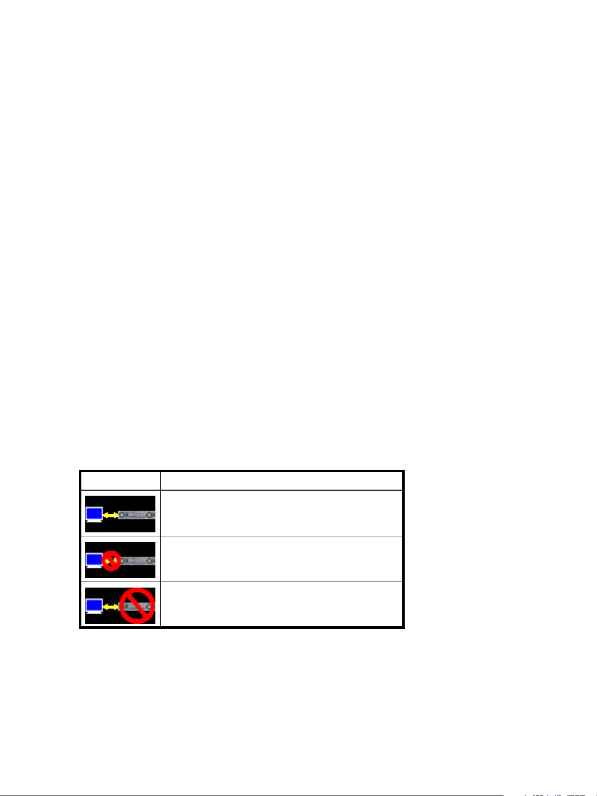
• The icon in the upper right corner of the main window shows the status of communication between
SMU, the Management Controller (MC), and the Storage Controller (SC), as described in the following
table.
Table 2 SMU communication status icons
Icon Meaning
• Below the communication status icon, a timer shows how long the session can be idle until you are
automatically signed out. This timer resets after each action you perform. One minute before automatic
sign-out you are prompted to continue using SMU. The timer does not appear if the current user's Auto
Sign Out preference is set to Never.
• If a SMU session is active on a controller and the controller is power cycled or is forced offline by the
partner controller or certain other events occur, the session might hang. SMU might say that it is
“Connecting” but stop responding, or the page may become blank with the browser status Done. After
the controller comes back online, the session will not restart. To continue using SMU, close and reopen
the browser and start a new SMU session.
14 Getting started
SMU can communicate with the Management Controller,
which can communicate with the Storage Controller.
SMU cannot communicate with the Management Controller.
SMU can communicate with the Management Controller,
which cannot communicate with the Storage Controller.
Page 15

Tips for using the help window
• In the main panel, click the help icon to display help for the last-selected item, whether it is a
component in the Configuration View panel or a subpanel in the main panel.
• In the help window, click the table of contents icon to show or hide the Contents pane.
• A help topic remains displayed until you browse to another topic in the help window, display help for a
different item in the main window, or close the help window.
• If you have viewed more than one help topic, you can click the arrow icons to display the previous or
next topic.
System concepts
About user accounts
The system provides three default user accounts and allows a maximum of 12 user accounts to be
configured. Any account can be modified or removed except you cannot remove the user you are signed in
as.
User accounts have these options:
• User Name. A user name is case sensitive and cannot already exist in the system. A name cannot
include a comma, double quote, or backslash.
• Password. A password is case sensitive. A password cannot include a comma, double quote, or
backslash. Though optional, passwords are highly recommended to ensure system security.
• Access Level. Select Monitor to let the user view system settings, or Manage to let the user view and
change system settings.
• User Type. Select Standard to allow access to standard functions, or Advanced to allow access to all
functions except diagnostic functions, or Diagnostic to allow access to all functions.
NOTE: This release has no functions that require Advanced or Diagnostic access; a Standard user can
access all functions.
• WBI Access. Allows access to the web-based management interface.
• CLI Access. Allows access to the command-line management interface.
• FTP Access. Allows access to the file transfer protocol interface, which provides a way to install
firmware updates and download logs.
• Base Preference. The base for entry and display of storage-space sizes. In base 2, sizes are shown as
powers of 2, using 1024 as a divisor for each magnitude. In base 10, sizes are shown as powers of 10,
using 1000 as a divisor for each magnitude. Operating systems usually show volume size in base 2.
Disk drives usually show size in base 10. Memory size is always shown in base 2.
• Precision Preference. The number of decimal places (1–10) for display of storage-space sizes.
• Unit Preference. Sets the unit for display of storage-space sizes. The Auto option lets the system
determine the proper unit for a size. Based on the precision setting, if the selected unit is too large to
meaningfully display a size, the system uses a smaller unit for that size.
• Temperature Preference. Specifies to use either the Celsius scale or the Fahrenheit scale for temperature
values.
• Auto Sign Out. Select the amount of time that the user's session can be idle before the user is
automatically signed out: 5, 15, or 30 minutes, or Never (9999 minutes). The default is 30 minutes.
HP StorageWorks 2000 G2 Modular Smart Array Reference Guide 15
Page 16

• Locale. The user’s preferred display language, which overrides the system’s default display language.
Installed language sets include Chinese-simplified, Chinese-traditional, Dutch, English, French,
German, Italian, Japanese, Korean, and Spanish.
Table 3 Settings for default users
Name Password Level Type WBI CLI FTP Base Prec. Units Temp. Auto
monitor !monitor Monitor Standard Yes Yes No 10 1 Auto
manage !manage Manage Yes Yes Yes
ftp !flash Manage No No Yes
NOTE: To secure the storage system, set a new password for each default user.
About vdisks
A vdisk is a “virtual” disk that is composed of one or more disks, and has the combined capacity of those
disks. The number of disks that a vdisk can contain is determined by its RAID level. All disks in a vdisk must
be the same type (SAS or SATA, small or large form-factor). A maximum of 16 vdisks per controller can
exist.
A vdisk can contain different models of disks, and disks with different capacities. For example, a vdisk can
include a 500-GB disk and a 750-GB disk. If you mix disks with different capacities, the smallest disk
determines the logical capacity of all other disks in the vdisk, regardless of RAID level. For example, if a
RAID-0 vdisk contains one 500-GB disk and four 750-GB disks, the capacity of the vdisk is equivalent to
approximately five 500-GB disks. To maximize capacity, use disks of similar size. For greatest reliability,
use disks of the same size and rotational speed.
Celsius
Sign
Out
30
Min.
Locale
English
Each disk has metadata that identifies whether the disk is a member of a vdisk, and other members of that
vdisk. This enables disks to be moved to different slots in a system; an entire vdisk to be moved to a
different system; and a vdisk to be quarantined if a disk is detected missing.
In a single-controller system, all vdisks are owned by that controller. In a dual-controller system, when a
vdisk is created the system automatically assigns the owner to balance the number of vdisks each controller
owns; or, you can select the owner. Typically it does not matter which controller owns a vdisk.
In a dual-controller system, when a controller fails, the partner controller assumes temporary ownership of
the failed controller's vdisks and resources. If the system uses a fault-tolerant cabling configuration, both
controllers' LUNs become accessible through the partner.
When you create a vdisk you can also create volumes within it. A volume is a logical subdivision of a
vdisk, and can be mapped to controller host ports for access by hosts. The storage system presents only
volumes, not vdisks, to hosts.
You can create vdisks with or without volumes by using the Provisioning Wizard, or you can create vdisks
manually.
About spares
A controller automatically reconstructs a redundant (fault-tolerant) vdisk (RAID 1, 3, 5, 6, 10, 50) when one
or more of its disks fails and a properly sized spare disk is available.
There are three types of spares:
• Dedicated spare. Reserved for use by a specific vdisk to replace a failed disk. Most secure way to
provide spares for vdisks but expensive to reserve a spare for each vdisk.
• Global spare. Reserved for use by any redundant vdisk to replace a failed disk.
• Dynamic spare. A properly sized available disk that is automatically assigned to replace a failed disk
in a redundant vdisk.
16 Getting started
Page 17

When a disk fails, the system looks for a dedicated spare first. If it does not find a properly sized
dedicated spare, it looks for a global spare. If it does not find a properly sized global spare and the
dynamic spares option is enabled, it takes any properly sized available disk. If no properly sized spares
are available, reconstruction cannot start.
About volumes
A volume is a logical subdivision of a vdisk, and can be mapped to controller host ports for access by
hosts. This type of volume provides the storage for a file system partition you create with your operating
system or third-party tools. The storage system presents only volumes, not vdisks, to hosts. A vdisk can have
a maximum of 128 volumes.
You can create a vdisk that has one volume or multiple volumes.
• Single-volume vdisks work well in environments that need one large, fault-tolerant storage space for
data on one host. A large database accessed by users on a single host that is used only for that
application is an example.
• Multiple-volume vdisks work well when you have very large disks and you want to make the most
efficient use of disk space for fault tolerance (parity and spares). For example, you could create one
very large RAID-5 vdisk and dedicate one spare to the vdisk. This minimizes the amount of disk space
allocated to parity and spares compared to the space required if you created five or six smaller RAID-5
vdisks. However, I/O to multiple volumes in the same vdisk can slow system performance.
When you create volumes you can specify their sizes. If the total size of a vdisk's volumes equals the size
of the vdisk, you will not have any free space. Without free space, you cannot add or expand volumes. If
you need to add or expand a volume in a vdisk without free space, you can delete a volume to create free
space. Or, you can expand the vdisk and then either add a volume or expand a volume to use the new
free space.
You can use a volume's default name or change it to identify the volume's purpose. For example, a volume
used to store payroll information can be named Payroll.
You can create vdisks with volumes by using the Provisioning Wizard, or you can create volumes manually.
About hosts
A host identifies an external port that the storage system is attached to. The external port may be a port in
an I/O adapter in a server, or a port in a network switch. Examples of I/O adapters are FC HBAs.
The controllers automatically add hosts that have sent an
to the storage system. Hosts typically do this when they boot up or rescan for devices. When the command
from the host occurs, the system saves the host ID. The ID for an FC or SAS host is its WWPN. The ID for an
iSCSI host is typically, but not limited to, its IQN.
You must assign a name to an automatically added host to have the system retain it after a restart. Naming
hosts also makes them easy to recognize for volume mapping. A maximum of 64 names can be assigned.
The Configuration View panel lists hosts by name, or if they are unnamed, by ID.
iSCSI host security
The storage system can be protected from unauthorized access via iSCSI by enabling Challenge
Handshake Authentication Protocol (CHAP). CHAP authentication occurs during an attempt by a host to
login to the system. This authentication requires an identifier for the host and a shared secret between the
host and the system. Optionally, the storage system can also be required to authenticate itself to the host;
this is called mutual CHAP.
The host node identifier is typically, but not limited to, its IQN. A secret can have 12–16 characters.
inquiry command or a report luns command
Steps involved in enabling CHAP include:
• Decide on host node names and secrets.
• Define CHAP entries in the storage system. If the node name is a host name, then it may be useful to
display the hosts that are known to the system.
• Enable CHAP on the storage system. Note that this applies to all iSCSI hosts, in order to avoid security
exposures.
HP StorageWorks 2000 G2 Modular Smart Array Reference Guide 17
Page 18

• Define CHAP secret in the host iSCSI initiator.
• Request host login to the storage system. The host should be displayable by the system, as well as the
ports through which connections were made.
If it becomes necessary to add more hosts after CHAP is enabled, additional CHAP node names and
secrets can be added. If a host attempts to login to the storage system, it will become visible to the system,
even if the full login is not successful due to incompatible CHAP definitions. This information may be useful
in configuring CHAP entries for new hosts. This information becomes visible when an iSCSI discovery
session is established, because the storage system does not require discovery sessions to be authenticated.
About volume mapping
Each volume has default host-access settings that are set when the volume is created; these settings are
called the default mapping. The default mapping applies to any host that has not been explicitly mapped
using different settings. Explicit mappings for a volume override its default mapping.
Default mapping enables all attached hosts to see a volume using a specified LUN and access permissions
set by the administrator. This means that when the volume is first created, all connected hosts can
immediately access the volume using the advertised default mapping settings. This behavior is expected by
some operating systems, such as Microsoft Windows, which can immediately discover the volume. The
advantage of a default mapping is that all connected hosts can discover the volume with no additional
work by the administrator. The disadvantage is that all connected hosts can discover the volume with no
restrictions. Therefore, this process is not recommended for specialized volumes such as payroll databases.
You can change a volume's default mapping, and create, modify, or delete explicit mappings. A mapping
can specify read-write, read-only, or no access through one or more controller host ports to a volume.
When a mapping specifies no access, the volume is masked. You can apply access privileges to one or
more of the host ports on either controller. To maximize performance, it is recommended to map a volume
to at least one host port on the controller that owns it. To sustain I/O in the event of controller failure, it is
recommended to map to at least one host port on each controller.
Continuing the example of the payroll volume, it could be mapped with read-write access for the Human
Resources host and be masked for all other hosts. An engineering volume could be mapped with read-write
access for the Engineering host and read-only access for other departments’ hosts.
A LUN identifies a mapped volume to a host. Both controllers share a set of LUNs, and any unused LUN
can be assigned to a mapping; however, each LUN can only be used once per volume as its default LUN.
For example, if LUN 5 is the default for Volume1, no other volume in the storage system can use LUN 5 as
its default LUN. For explicit mappings, the rules differ: LUNs used in default mappings can be reused in
explicit mappings for other volumes and other hosts.
TIP: When an explicit mapping is deleted, the volume’s default mapping takes effect. Therefore, it is
recommended to use the same LUN for explicit mappings as for the default mapping.
Volume mapping settings are stored in disk metadata. If enough of the disks used by a volume are moved
into a different enclosure, the volume's vdisk can be reconstructed and the mapping data is preserved.
18 Getting started
Page 19

About volume cache options
You can set options that optimize reads and writes performed for each volume.
Using write-back or write-through caching
NOTE: Only disable write-back caching if you fully understand how the host operating system,
application, and adapter move data. If used incorrectly, you might hinder system performance.
You can change a volume's write-back cache setting. Write-back is a cache-writing strategy in which the
controller receives the data to be written to disks, stores it in the memory buffer, and immediately sends the
host operating system a signal that the write operation is complete, without waiting until the data is actually
written to the disk. Write-back cache mirrors all of the data from one controller module cache to the other.
Write-back cache improves the performance of write operations and the throughput of the controller.
When write-back cache is disabled, write-through becomes the cache-writing strategy. Using write-through
cache, the controller writes the data to the disks before signaling the host operating system that the process
is complete. Write-through cache has lower write operation and throughput performance than write-back,
but it is the safer strategy, with minimum risk of data loss on power failure. However, write-through cache
does not mirror the write data because the data is written to the disk before posting command completion
and mirroring is not required. You can set conditions that cause the controller to change from write-back
caching to write-through caching.
In both caching strategies, active-active failover of the controllers is enabled.
You can enable and disable the write-back cache for each volume. By default, volume write-back cache is
enabled. Because controller cache is backed by super-capacitor technology, if the system loses power,
data is not lost. For most applications, this is the correct setting. But because back-end bandwidth is used to
mirror cache and because this mirroring uses back-end bandwidth, if you are writing large chunks of
sequential data (as would be done in video editing, telemetry acquisition, or data logging), write-through
cache has much better performance. Therefore, you might want to experiment with disabling the write-back
cache. You might see large performance gains (as much as 70 percent) if you are writing data under the
following circumstances:
• Sequential writes
• Large I/Os in relation to the chunk size
• Deep queue depth
If you are doing random access to this volume, leave the write-back cache enabled.
Optimizing read-ahead caching
CAUTION: Only change read-ahead cache settings if you fully understand how the host operating
system, application, and adapter move data so that you can adjust the settings accordingly.
You can optimize a volume for sequential reads or streaming data by changing its read-ahead cache
settings. Read ahead is triggered by two back-to-back accesses to consecutive LBA ranges, whether
forward (increasing LBAs) or reverse (decreasing LBAs).
You can change the amount of data read in advance after two back-to-back reads are made. Increasing
the read-ahead cache size can greatly improve performance for multiple sequential read streams; however,
increasing read-ahead size will likely decrease random read performance.
• The Default option works well for most applications: it sets one chunk for the first access in a sequential
read and one stripe for all subsequent accesses. The size of the chunk is based on the chunk size used
when you created the vdisk (the default is 64 KB). Non-RAID and RAID-1 vdisks are considered to have
a stripe size of 64 KB.
• Specific size options let you select an amount of data for all accesses.
HP StorageWorks 2000 G2 Modular Smart Array Reference Guide 19
Page 20
• The Maximum option lets the controller dynamically calculate the maximum read-ahead cache size for
the volume. For example, if a single volume exists, this setting enables the controller to use nearly half
the memory for read-ahead cache. Only use Maximum when disk latencies must be absorbed by
cache.
• The Disabled option turns off read-ahead cache. This is useful if the host is triggering read ahead for
what are random accesses. This can happen if the host breaks up the random I/O into two smaller
reads, triggering read ahead.
You can also change the optimization mode. The standard read-ahead caching mode works well for
typical applications where accesses are a combination of sequential and random; this method is the
default. For an application that is strictly sequential and requires extremely low latency, you can use Super
Sequential mode. This mode makes more room for read-ahead data by allowing the controller to discard
cache contents that have been accessed by the host.
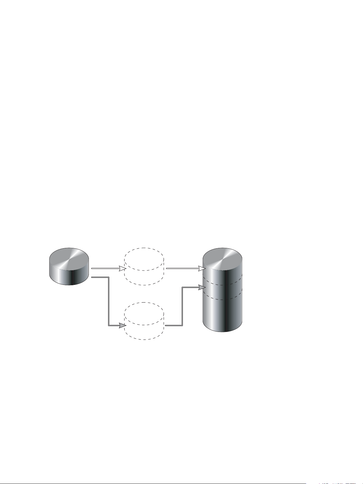
About the Snapshot feature
Snapshot is a licensed feature that provides data protection by enabling you to create and save snapshots
of a volume. Each snapshot preserves the source volume's data state at the point in time when the snapshot
was created. Snapshots can be created manually or by using the task scheduler.
When the first snapshot is taken of a standard volume, the system automatically converts the volume into a
master volume and reserves additional space for snapshot data. This reserved space, called a snap pool,
stores pointers to the source volume's data. Each master volume has its own snap pool. The system treats a
snapshot like any other volume; the snapshot can be mapped to hosts with read-only access, read-write
access, or no access, depending on the snapshot's purpose. Any additional unique data written to a
snapshot is also stored in the snap pool.
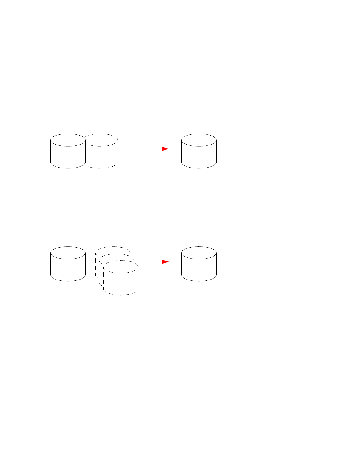
The following figure shows how the data state of a master volume is preserved in the snap pool by two
snapshots taken at different points in time. The dotted line used for the snapshot borders indicates that
snapshots are logical volumes, not physical volumes as are master volumes and snap pools.
MasterVolume-1 Snap Pool-1
Snapshot-1
(Monday)
Snapshot-2
(Tuesday)
Figure 1 Relationship between a master volume and its snapshots and snap pool
The snapshot feature uses the single copy-on-write method to capture only data that has changed. That is,
if a block is to be overwritten on the master volume, and a snapshot depends on the existing data in the
block being overwritten, the data is copied from the master volume to the snap pool before the data is
changed. All snapshots that depend on the older data are able to access it from the same location in the
snap pool; this reduces the impact of snapshots when writing to a master volume. In addition, only a single
copy-on-write operation is performed on the master volume.
The storage system allows a maximum number of snapshots to be retained, as determined by an installed
license. For example, if your license allows four snapshots, when the fifth snapshot is taken an error
message informs you that you have reached the maximum number of snapshots allowed on your system.
Before you can create a new snapshot you must either delete an existing snapshot, or purchase and install
a license that increases the maximum number of snapshots.
20 Getting started
Page 21
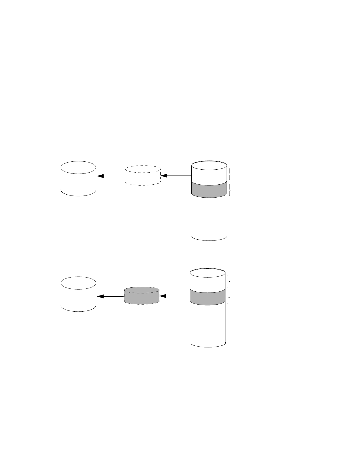
The snapshot service has two features for reverting data back to original data:
• Deleting only modified data on a snapshot. For snapshots that have been made accessible as
read-write, you can delete just the modified (write) data that was written directly to a snapshot. When
the modified data is deleted, the snapshot data reverts to the original data that was snapped. This
feature is useful for testing an application, for example. You might want to test some code, which writes
data to the snapshot. Rather than having to take another snapshot, you can just delete any write data
and start again.
• Rolling back the data in a source volume. The rollback feature enables you to revert the data in a
source volume to the data that existed when a specified snapshot was created (preserved data).
Alternatively, the rollback can include data that has been modified (write data) on the snapshot since
the snapshot was taken. For example, you might want to take a snapshot, mount that snapshot for
read/write, and then install new software on that snapshot for test purposes. If the software installation
is successful, you can rollback the master volume to the contents of the modified snapshot (preserved
data plus the write data).
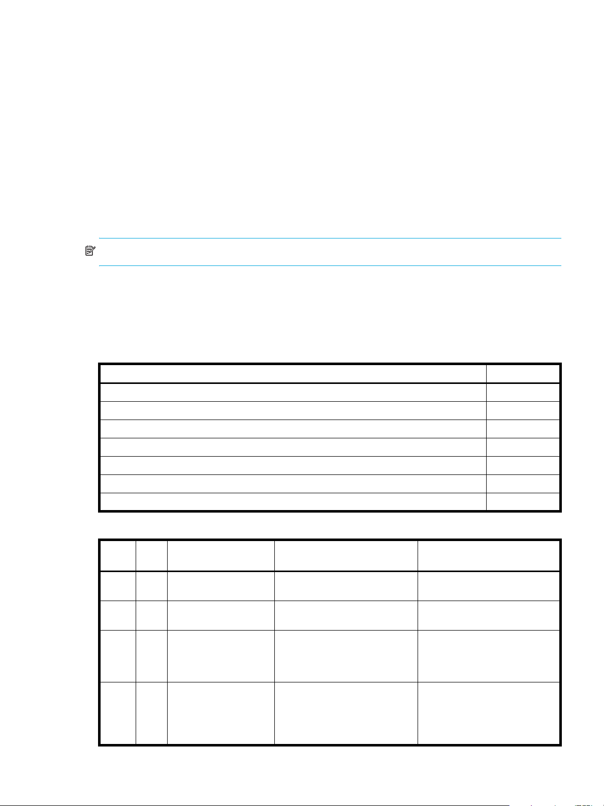
The following figure shows the difference between rolling back the master volume to the data that
existed when a specified snapshot was created (preserved), and rolling back preserved and modified
data.
MasterVolume-1
Snapshot-1
Preserved Data
(Monday)
Modified Data
(Tuesday)
When you use the rollback feature, you
can choose to exclude the modified data,
which will revert the data on the master
volume to the preserved data when
the snapshot was taken.
MasterVolume-1
Or you can choose to include the modified
data since the snapshot was taken, which
will revert the data on the master volume
to the current snapshot.
Figure 2 Rolling back a master volume
About the Volume Copy feature
Snap Pool-1
Snapshot-1
Preserved Data
(Monday)
Modified Data
(Tuesday)
Snap Pool-1
Volume Copy is a licensed feature that enables you to copy a volume or a snapshot to a new standard
volume.
While a snapshot is a point-in-time logical copy of a volume, the volume copy service creates a complete
“physical” copy of a volume within a storage system. It is an exact copy of a source volume as it existed at
the time the volume copy operation was initiated, consumes the same amount of space as the source
volume, and is independent from an I/O perspective. Volume independence is a key distinction of a
volume copy (versus a snapshot, which is a “virtual” copy and dependent on the source volume).
HP StorageWorks 2000 G2 Modular Smart Array Reference Guide 21
Page 22
Benefits include:
• Additional data protection. An independent copy of a volume (versus logical copy through snapshot)
provides additional data protection against a complete master volume failure. If the source master
volume fails, the volume copy can be used to restore the volume to the point in time the volume copy
was taken.
• Non-disruptive use of production data. With an independent copy of the volume, resource contention
and the potential performance impact on production volumes is mitigated. Data blocks between the
source and the copied volumes are independent (versus shared with snapshot) so that I/O is to each
set of blocks respectively; application I/O transactions are not competing with each other when
accessing the same data blocks.
The following figure illustrates how volume copies are created.
Creating a volume copy from a standard or master volume
Source volume Transient snapshot Data transfer New volume
1. Volume copy request is made with a standard volume or a master volume as the source.
2. If the source a standard volume, it is converted to a master volume and a snap pool is created.
3. A new volume is created for the volume copy, and a hidden, transient snapshot is created.
4. Data is transferred from the transient snapshot to the new volume.
5. On completion, the transient volume is deleted and the new volume is a completely independent copy of
the master volume, representing the data that was present when the volume copy was started.
Creating a volume copy from a snapshot
Master volume
1. A master volume exists with one or more snapshots associated with it. Snapshots can be in their original
state or they can be modified.
2. You can select any snapshot to copy, and you can specify that the modified or unmodified data be copied.
3. On completion, the new volume is a completely independent copy of the snapshot. The snapshot remains,
though you can choose to delete it.
Snapshot(s) Data transfer New volume
Figure 3 Creating a volume copy from a master volume or a snapshot
Guidelines to keep in mind when performing a volume copy include:
• The destination vdisk must be owned by the same controller as the source volume.
• The destination vdisk must have free space that is at least as large as the mount of space allocated to
the original volume. A new volume will be created using this free space for the volume copy.
• The destination vdisk does not need to have the same attributes (such as disk type, RAID level) as the
volume being copied.
• Once the copy is complete, the new volume will no longer have any ties to the original.
• Volume Copy makes a copy from a snapshot of the source volume; therefore, the snap pool for the
source volume must have sufficient space to store snapshot data when performing this copy.
22 Getting started
Page 23
About the VDS and VSS hardware providers
Virtual Disk Service (VDS) enables host-based applications to manage vdisks and volumes. Volume
Shadow Copy Service (VSS) enables host-based applications to manage snapshots. For more information,
see the VDS and VSS hardware provider documentation for your product.
About RAID levels
The RAID controllers enable you to set up and manage vdisks, whose storage may be spread across
multiple disks. This is accomplished through firmware resident in the RAID controller. RAID refers to vdisks
in which part of the storage capacity may be used to store redundant data. The redundant data enables
the system to reconstruct data if a disk in the vdisk fails.
Hosts see each partition of a vdisk, known as a volume, as a single disk. A volume is actually a portion of
the storage space on disks behind a RAID controller. The RAID controller firmware makes each volume
appear as one very large disk. Depending on the RAID level used for a vdisk, the disk presented to hosts
has advantages in fault-tolerance, cost, performance, or a combination of these.
NOTE: Choosing the right RAID level for your application improves performance.
The following tables:
• Provide examples of appropriate RAID levels for different applications
• Compare the features of different RAID levels
• Describe the expansion capability for different RAID levels
Table 4 Example applications and RAID levels
Application RAID level
Testing multiple operating systems or software development (where redundancy is not an issue) NRAID
Fast temporary storage or scratch disks for graphics, page layout, and image rendering 0
Workgroup ser vers 1 or 10
Video editing and production 3
Network operating system, databases, high availability applications, workgroup servers 5
Very large databases, web server, video on demand 50
Mission-critical environments that demand high availability and use large sequential workloads 6
Table 5 RAID level comparison
RAID
level
NRAID 1 Non-RAID, nonstriped
0 2 Data striping without
1 2 Disk mirroring Very high performance and data
Min.
disks
Description Strengths Weaknesses
mapping to a single disk
redundancy
Ability to use a single disk to store
additional data
Highest performance No data protection: if one disk
protection; minimal penalty on
write performance
Not protected, lower performance
(not striped)
fails all data is lost
High redundancy cost overhead:
because all data is duplicated,
twice the storage capacity is
required
3 3 Block-level data striping
with dedicated parity
disk
Excellent performance for large,
sequential data requests (fast
read)
HP StorageWorks 2000 G2 Modular Smart Array Reference Guide 23
Not well-suited for
transaction-oriented network
applications: single parity disk
does not support multiple,
concurrent write requests
Page 24

Table 5 RAID level comparison (continued)
RAID
level
5 3 Block-level data striping
6 4 Block-level data striping
10
(1+0)
50
(5+0)
Min.
Description Strengths Weaknesses
disks
with distributed parity
with double distributed
parity
4 Stripes data across
multiple RAID-1
sub-vdisks
6 Stripes data across
multiple RAID-5
sub-vdisks
Best cost/performance for
transaction-oriented networks;
very high performance and data
protection; supports multiple
simultaneous reads and writes;
can also be optimized for large,
sequential requests
Best suited for large sequential
workloads; non-sequential read
and sequential read/write
performance is comparable to
RAID 5
Highest performance and data
protection (can tolerate multiple
disk failures)
Better random read and write
performance and data protection
than RAID 5; supports more disks
than RAID 5
Write performance is slower than
RAID 0 or RAID 1
Higher redundancy cost than
RAID 5 because the parity
overhead is twice that of RAID 5;
not well-suited for
transaction-oriented network
applications; non-sequential write
performance is slower than RAID
5
High redundancy cost overhead:
because all data is duplicated,
twice the storage capacity is
required; requires minimum of four
disks
Lower storage capacity than RAID
5
Table 6 Vdisk expansion by RAID level
RAID level Expansion capability Maximum disks
NRAID Cannot expand. 1
0, 3, 5, 6 You can add 1–4 disks at a time. 16
1Cannot expand. 2
10 You can add 2 or 4 disks at a time. 16
50 You can add one sub-vdisk at a time. The added sub-vdisk must contain the same
number of disks as each of the existing sub-vdisks.
32
24 Getting started
Page 25

About size representations
In SMU panels, parameters such as names of users and volumes have a maximum length in bytes. ASCII
characters are 1 byte; most Latin (Western European) characters with diacritics are 2 bytes; most Asian
characters are 3 bytes.
Operating systems usually show volume size in base 2. Disk drives usually show size in base 10. Memory
size is always shown in base 2. In SMU, the base for entry and display of storage-space sizes can be set
per user or per session. When entering storage-spaces sizes only, either base-2 or base-10 units can be
specified.
Table 7 Size representations in base 2 and base 10
Base 2 Base 10
Unit Size in bytes Unit Size in bytes
KiB (kibibyte) 210 (1,024) KB ( ki l ob y te) 103 (1,0 0 0 )
MiB (mebibyte) 220 (1,048,576) MB (megabyte) 106 (1,000,000)
GiB (gibibyte) 230 (1,073,741,824) GB (gigabyte) 109 (1,000,000,000)
TiB (tebibyte) 240 (1,099,511,627,776) TB (terabyte) 1012 (1,000,000,000,000)
The locale setting determines the character used for the decimal (radix) point, as shown below.
Table 8 Decimal (radix) point character by locale
Language Character Examples
English, Chinese, Japanese, Korean Period (.) 146.81 GB
Dutch, French, German, Italian, Spanish Comma (,) 146,81 GB
About the system date and time
You can change the storage system's date and time, which are displayed in the System Status panel. It is
important to set the date and time so that entries in system logs and event-notification email messages have
correct time stamps.
You can set the date and time manually or configure the system to use Network Time Protocol (NTP) to
obtain them from a network-attached server. When NTP is enabled, and if an NTP server is available, the
system time and date can be obtained from the NTP server. This allows multiple storage devices, hosts, log
files, and so forth to be synchronized. If NTP is enabled but no NTP server is present, the date and time are
maintained as if NTP was not enabled.
NTP server time is provided in Universal Time (UT), which provides several options:
• If you want to synchronize the times and logs between storage devices installed in multiple time zones,
set all the storage devices to use UT.
• If you want to use the local time for a storage device, set its time zone offset.
• If a time server can provide local time rather than UT, configure the storage devices to use that time
server, with no further time adjustment.
3.0 Gb/s
3,0 Gb/s
Whether NTP is enabled or disabled, the storage system does not automatically make time adjustments,
such as for U.S. daylight savings time. You must make such adjustments manually.
HP StorageWorks 2000 G2 Modular Smart Array Reference Guide 25
Page 26
About storage-space color codes
SMU panels use the following color codes to identify how storage space is used.
Table 9 Storage-space color codes
Area Color Meaning
Overview panels Total space
Available/free space
Used space
Reserved space, used for parity and snap pools, for example
Vdisk panels Space used by spares
Wasted space, due to use of mixed disk sizes
About vdisk reconstruction
If one or more disks fail in a redundant vdisk (RAID 1, 3, 5, 6, 10, or 50) and properly sized spares are
available, the storage system automatically uses the spares to reconstruct the vdisk. Vdisk reconstruction
does not require I/O to be stopped, so the vdisk can continue to be used while the Reconstruct utility runs.
A properly sized spare is one whose capacity is equal to or greater than the smallest disk in the vdisk. If no
properly sized spares are available, reconstruction does not start automatically. To start reconstruction
manually, replace each failed disk and then do one of the following:
• Add each new disk as either a dedicated spare or a global spare. Remember that a global spare might
be taken by a different critical vdisk than the one you intended.
• Enable the Dynamic Spare Capability option to use the new disks without designating them as spares.
Reconstructing a RAID-6 vdisk to a fault-tolerant state requires two properly sized spares to be available.
• If two disks fail and only one properly sized spare is available, an event indicates that reconstruction is
about to start. The Reconstruct utility starts to run, using the spare, but its progress remains at 0% until a
second properly sized spare is available.
• If a disk fails during online initialization, the initialization fails. In order to generate the two sets of
parity that RAID 6 requires, the controller fails a second disk in the vdisk, which changes the vdisk
status to Critical, and then assigns that disk as a spare for the vdisk. The Reconstruct utility starts to run,
using the spare, but its progress remains at 0% until a second properly sized spare is available.
The second available spare can be an existing global spare, another existing spare for the vdisk, or a
replacement disk that you designate as a spare or that is automatically taken when dynamic sparing is
enabled.
During reconstruction, you can continue to use the vdisk. When a global spare replaces a disk in a vdisk,
the global spare’s icon in the enclosure view changes to match the other disks in that vdisk.
NOTE: Reconstruction can take hours or days to complete, depending on the vdisk RAID level and size,
disk speed, utility priority, and other processes running on the storage system. You can stop reconstruction
only by deleting the vdisk.
26 Getting started
Page 27

About data protection in a single-controller storage system
A 2000 G2 Modular Smart Array storage system can be purchased or operated with a single controller.
Because single-controller mode is not a redundant configuration, this section presents some considerations
concerning data protection.
A volume’s default caching mode is write back, as opposed to write through. In write-back mode, data is
held in controller cache until it is written to disk. In write-through mode, data is written directly to disk.
If the controller fails while in write-back mode, unwritten cache data likely exists. The same is true if the
controller enclosure or the target volume's enclosure is powered off without a proper shut down. Data
remains in the controller's cache and associated volumes will be missing that data. This can result in data
loss or in some cases volume loss; for example, if using snapshot functionality a snap pool might become
inaccessible and the master volume could go offline.
If the controller can be brought back online long enough to perform a proper shut down, the controller
should be able to write its cache to disk without causing data loss.
If the controller cannot be brought back online long enough to write its cache data to disk, you can move
its CompactFlash cache card to a replacement controller. This enables the cache data to be available
when the new controller comes online. The CompactFlash card is externally accessible from the back of the
controller.
To avoid the possibility of data loss in case the controller fails you can change a volume's caching mode to
write through. While this will cause significant performance degradation, this configuration guards against
data loss. While write-back mode is much faster, this mode is not guaranteed against data loss in the case
of a controller failure. If data protection is more important, use write-through caching; if performance is
more important, use write-back caching.
For details about caching modes see About volume cache options on page 19. To change a volume’s
caching mode, see Changing a volume's cache settings on page 44.
HP StorageWorks 2000 G2 Modular Smart Array Reference Guide 27
Page 28

28 Getting started
Page 29

2Configuring the system
Using the Configuration Wizard
The Configuration Wizard helps you initially configure the system or change system configuration settings.
The wizard has several steps, which are highlighted at the bottom of the panel as you complete them. The
last step prompts you to confirm changes before applying them. If you cancel the wizard, no changes are
made.
Step 1: Starting the wizard
1. In the Configuration View panel, right-click the system and select either Configuration > Configuration
Wizard or Wizards > Configuration Wizard. The wizard panel appears.
2. Click Next to continue.
Step 2: Change default passwords
The system provides the default users manage and monitor. To secure the storage system, set a new
password for each default user. A password is case sensitive. A password cannot include a comma,
double quote, or backslash. Though optional, passwords are highly recommended to ensure system
security.
Click Next to continue.
Step 3: Configuring network ports
You can configure addressing parameters for each controller's network port. You can set static IP values or
use DHCP.
In DHCP mode, network port IP address, subnet mask, and gateway values are obtained from a DHCP
server if one is available. If a DHCP server is unavailable, current addressing is unchanged. You must have
some means of determining what addresses have been assigned, such as the list of bindings on the DHCP
server.
NOTE: Changing IP settings can cause management hosts to lose access to the storage system.
To use DHCP to obtain IP values for network ports
1. Set IP address source to DHCP.
2. Click Next to continue.
To set static IP values for network ports
1. Determine the IP address, subnet mask, and gateway values to use for each controller.
2. Set IP address source to manual.
3. Set the values for each controller. You must set a unique IP address for each network port.
4. Click Next to continue.
Step 4: Enabling system-management services
You can enable or disable management-interface services to limit the ways in which users and host-based
management applications can access the storage system. Network management interfaces operate
out-of-band and do not affect host I/O to the system. The network options are:
• Web Browser Interface (WBI). The primary interface for managing the system. You can enable use of
HTTP, of HTTPS for increased security, or both.
• Command Line Interface (CLI). An advanced user interface for managing the system. You can enable
use of Telnet, of SSH (secure shell) for increased security, or both.
• Storage Management Initiative Spec. (SMIS). Used for remote management of the system through your
network.
HP StorageWorks 2000 G2 Modular Smart Array Reference Guide 29
Page 30

• File Transfer Protocol (FTP). A secondary interface for installing firmware updates, downloading logs,
and installing a license.
• Simple Network Management Protocol (SNMP). Used for remote monitoring of the system through your
network.
• Service Interface. Used for technical support only.
• Service Debug. Used for technical support only.
In-band management interfaces operate through the data path and can slightly reduce I/O performance.
The in-band options are:
• In-band CAPI Capability. Used for in-band management of the system from custom, host-based
management applications written using the Configuration Application Programming Interface (CAPI).
• In-band SES Capability. Used for in-band monitoring of system status based on SCSI Enclosure Services
(SES) data.
If a service is disabled, it continues to run but cannot be accessed. To allow users to access WBI, CLI, or
FTP, see About user accounts on page 15.
To change management interface settings
1. Enable the options that you want to use to manage the storage system, and disable the others.
2. Click Next to continue.
Step 5: Setting system information
Enter a name, contact person, location, and description for the system. The system name is shown in the
browser title bar or tab. All four values are recorded in system debug logs for reference by service
personnel. Click Next to continue.
Step 6: Configuring event notification
Configure up to four email addresses and three SNMP trap hosts to receive notifications of system events.
1. In the Email Configuration section, set the options:
• Notification Level. Select the minimum severity for which the system should send notifications:
Critical (only); Warning (and Critical); Informational (all). The default is none, which disables email
notification.
• SMTP Server address. The IP address of the SMTP mail server to use for the email messages. If the
mail server is not on the local network, make sure that the gateway IP address was set in the
network configuration step.
• Sender Name. The sender name that, with the domain name, forms the “from” address for remote
notification. Because this name is used as part of an email address, do not include spaces. If no
sender name is set, a default name is created.
• Sender Domain. The domain name that, with the sender name, forms the “from” address for remote
notification. Because this name is used as part of an email address, do not include spaces. If no
domain name is set here, the default domain value is used. If the domain name is not valid, some
email servers will not process the mail.
• Email Address fields. Up to four email addresses that the system should send notifications to. Email
addresses must use the format user-name@domain-name.
2. In the SNMP Configuration section, set the options:
• Notification Level. Select the minimum severity for which the system should send notifications:
Critical (only); Warning (and Critical); Informational (all). The default is none, which disables
SNMP notification.
• Read Community. The SNMP read password for your network. The value is case sensitive. The
default is
• Write Community. The SNMP write password for your network. The value is case sensitive. The
default is
• Trap Host Address fields. IP addresses of up to three host systems that are configured to receive
SNMP traps.
public.
private.
30 Configuring the system
Page 31

3. Click Next to continue.
Step 7: Configuring host ports
In order for hosts to properly access the system, you must configure the system's host-interface options.
For FC ports you can set these options:
• Speed can be set to auto, which auto-negotiates the proper link speed with the host, or to 2Gb (Gbit
per second) or 4Gb. A speed mismatch with a host prevents that host from accessing the storage
system.
• Connection mode can be set to loop or point-to-point. Loop protocol can be used in a physical loop or
in a direct physical connection between two devices. Point-to-point protocol can only be used on a
direct physical connection between exactly two devices.
• Loop IDs can be set, per controller, to use soft or hard target addressing:
• Soft target addressing (the default) enables a LIP to determine the loop ID. Use this setting if the loop
ID is permitted to change after a LIP or power cycle.
• Hard target addressing requests a specific loop ID that should remain after a LIP or power cycle. If
the port cannot acquire the specified ID, it is assigned a soft target address. Use this option if you
want ports to have specific addresses, if your system checks addresses in reverse order (lowest
address first), or if an application requires that specific IDs be assigned to recognize the controller.
For iSCSI ports you can set these options:
• IP Address. The port IP address in IPv4 format.
• Netmask. The port netmask address in IPv4 format.
• Gateway. The port gateway address in IPv4 format.
• Authentication (CHAP). Enables or disables use of Challenge Handshake Authentication Protocol.
Disabled by default.
• Jumbo Frames. Enables or disables support for jumbo frames. A normal frame can contain 1500 bytes
whereas a jumbo frame can contain a maximum of 9000 bytes for larger data transfers. Disabled by
default.
NOTE: Use of jumbo frames can succeed only if jumbo-frame support is enabled on all network
components in the data path.
• Link Speed. Sets the link speed to auto, which allows the system to negotiate the proper speed, or
forces it to 1 Gbit/sec (1g). The default is auto.
• iSNS. Enables or disables registration with a specified Internet Storage Name Service server, which
provides name-to-IP-address mapping. Disabled by default.
• iSNS Address. Specifies the IP address of an iSNS server. The default address is all zeroes.
• Alternate iSNS Address. Specifies the IP address of an alternate iSNS server, which can be on a
different subnet. The default address is all zeroes.
For SAS ports there are no host-interface options. Click Next to continue.
To change FC host-interface settings
1. For controller host ports that are attached to hosts:
• Set the speed to the proper value to communicate with the host.
• Set the connection mode to loop or point-to-point.
2. For each controller, set the loop ID to use soft or hard target addressing. To use soft target addressing,
select Soft?. To use hard target addressing, clear Soft? and enter an address in the range 0–125. You
cannot set the same hard target address for both controllers. An asterisk indicates that the value shown
will be changed.
3. Click Next to continue.
HP StorageWorks 2000 G2 Modular Smart Array Reference Guide 31
Page 32

To change iSCSI host-interface settings
1. For each iSCSI port, set the IP address, netmask, and gateway.
2. For all iSCSI ports, set the authentication, jumbo frames, link speed, and iSNS options.
3. Click Next to continue.
Step 8: Confirming configuration changes
Confirm that the values listed in the wizard panel are correct.
• If they are not correct, click Previous to return to previous steps and make necessary changes.
• If they are correct, click Finish to apply the setting changes and finish the wizard.
NOTE: If you changed a controller’s FC loop ID setting, you must restart the controller to make the change
take effect.
Installing a license
A license is required to expand Snapshot limits and to use Volume Copy. The license is specific to a
controller enclosure serial number and firmware version.
If a permanent license is not installed and you want to try the Snapshot and Volume Copy features before
buying a permanent license, you can create a temporary license one time. A temporary license will expire
60 days from the time it is created. After creating a temporary license, each time you sign in to SMU, a
message specifies the time remaining in the trial period. If you do not install a permanent license before the
temporary license expires, you cannot create new snapshots or volume copies; however, you can continue
to use existing snapshots and volume copies.
After a temporary license is created or a permanent license is installed, the option to create a temporary
license is no longer displayed.
To view information about system licenses
In the Configuration View panel, right-click the system and select Tools > Install License.
The System Licenses table shows the following information about licensed features:
• License Key. The license key number or “not installed” if no license is installed.
• Licensed Snapshots. The number of snapshots that the installed license provides.
• Maximum Licensable Snapshots. The number of snapshots that the product supports.
• Volume Copy. Shows whether volume copy functions are enabled or disabled.
• VDS. Shows that the VDS (Virtual Disk Service) Hardware Provider is enabled.
• VSS. Shows that the VSS (Virtual Shadow Copy Service) Hardware Provider is enabled.
• License Duration. Shows the number of days remaining in the trial period if a temporary license is
installed.
The panel also shows the licensing serial number (controller enclosure serial number) and licensing version
number (controller firmware version), for which a license file must be generated in order to successfully
install.
To create a temporary license
1. In the Configuration View panel, right-click the system and select Tools > Install License. If the option to
create a temporary license is available, the End User License Agreement appears in the lower portion
of the license panel.
2. Read the license agreement.
3. If you accept the terms of the license agreement, select the checkbox. A confirmation dialog appears.
4. Click Yes to start the trial period. The time remaining in the trial period is shown in the panel's License
Duration field.
32 Configuring the system
Page 33

To install a permanent license
1. Ensure that:
• The license file is saved to a network location that SMU can access.
• You are signed into the controller enclosure that the file was generated for.
2. In the Configuration View panel, right-click the system and select Tools > Install License.
3. Click Browse to locate and select the license file.
4. Click Install License File. If installation succeeds, the System Licenses table is updated. The licensing
changes take effect immediately.
Configuring system services
Changing management interface settings
You can enable or disable management interfaces to limit the ways in which users and host-based
management applications can access the storage system. Network management interfaces operate
out-of-band and do not affect host I/O to the system. The network options are:
• Web Browser Interface (WBI). The primary interface for managing the system. You can enable use of
HTTP, of HTTPS for increased security, or both.
• Command Line Interface (CLI). An advanced user interface for managing the system. You can enable
use of Telnet, of SSH (secure shell) for increased security, or both.
• Storage Management Initiative Specification (SMIS). Used for remote management of the system
through your network.
• File Transfer Protocol (FTP). A secondary interface for installing firmware updates, downloading logs,
and installing a license.
• Simple Network Management Protocol (SNMP). Used for remote monitoring of the system through your
network.
• Service Interface. Used for technical support only.
• Service Debug. Used for technical support only.
In-band management interfaces operate through the data path and can slightly reduce I/O performance.
The in-band options are:
• In-band CAPI Capability. Used for in-band management of the system from custom, host-based
management applications written using the Configuration Application Programming Interface (CAPI).
• In-band SES Capability. Used for in-band monitoring of system status based on SCSI Enclosure Services
(SES) data.
If a service is disabled, it continues to run but cannot be accessed. To allow users to access WBI, CLI, or
FTP, see About user accounts on page 15.
To change management interface settings
1. In the Configuration View panel, right-click the system and select Configuration > Services >
Management.
2. In the Network Management Services section, enable the options that you want to use to manage the
storage system, and disable the others.
3. Click Apply. If you disabled any options, a confirmation dialog appears.
4. Click Yes to continue; otherwise, click No. If you clicked No, a processing dialog appears. When
processing is complete a success dialog appears.
5. Click OK.
HP StorageWorks 2000 G2 Modular Smart Array Reference Guide 33
Page 34

Configuring email notification
To configure email notification of events
1. In the Configuration View panel, right-click the system and select Configuration > Services > Email
Notification.
2. In the main panel, set the options:
• Notification Level. Select the minimum severity for which the system should send notifications:
Critical (only); Warning (and Critical); Informational (all). The default is none, which disables email
notification.
• SMTP Server address. The IP address of the SMTP mail server to use for the email messages. If the
mail server is not on the local network, make sure that the gateway IP address is set in System
Settings > Network Interfaces.
• Sender Name. The sender name that, with the domain name, forms the “from” address for remote
notification. Because this name is used as part of an email address, do not include spaces. If no
sender name is set, a default name is created.
• Sender Domain. The domain name that, with the sender name, forms the “from” address for remote
notification. Because this name is used as part of an email address, do not include spaces. If no
domain name is set here, the default domain value is used. If the domain name is not valid, some
email servers will not process the mail.
• Email Address fields. Up to four email addresses that the system should send notifications to. Email
addresses must use the format user-name@domain-name.
3. Click Apply.
Configuring SNMP notification
To configure SNMP notification of events
1. In the Configuration View panel, right-click the system and select Configuration > Services > SNMP
Notification.
2. In the main panel, set the options:
• Notification Level. Select the minimum severity for which the system should send notifications:
Critical (only); Warning (and Critical); Informational (all). The default is none, which disables
SNMP notification.
• Read Community. The SNMP read password for your network. The value is case sensitive. The
default is public.
• Write Community. The SNMP write password for your network. The value is case sensitive. The
default is private.
• Trap Host Address fields. IP addresses of up to three host systems that are configured to receive
SNMP traps.
3. Click Apply
Configuring user accounts
Adding users
To add a user
1. In the Configuration View panel, right-click the system and select Configuration > Users > Add User.
2. In the main panel, set the options:
• User Name. A user name is case sensitive and cannot already exist in the system. A name cannot
include a comma, double quote, or backslash.
• Password. A password is case sensitive. A password cannot include a comma, double quote, or
backslash. Though optional, passwords are highly recommended to ensure system security.
• Access Level. Select Monitor to let the user view system settings, or Manage to let the user view and
change system settings.
34 Configuring the system
Page 35

• User Type. Select Standard to allow access to standard functions, or Advanced to allow access to
all functions except diagnostic functions, or Diagnostic to allow access to all functions.
NOTE: This release has no functions that require Advanced or Diagnostic access; a Standard user
can access all functions.
• WBI Access. Allows access to the web-based management interface.
• CLI Access. Allows access to the command-line management interface.
• FTP Access. Allows access to the file transfer protocol interface, which provides a way to install
firmware updates and download logs.
• Base Preference. Select Base 2 to show sizes as powers of 2 (binary) using 1024 as a divisor, or
Base 10 to show sizes as powers of 10 (decimal) using 1000 as a divisor.
• Precision Preference. Number of decimal places to use for sizes.
• Unit Preference. Select Auto to let the system determine the proper units for sizes, or select the units
to use for all sizes.
• Temperature Preference. Specifies to use either the Celsius scale or the Fahrenheit scale for
temperature values.
• Auto Sign Out. Select the amount of time that the user's session can be idle before the user is
automatically signed out: 5, 15, or 30 minutes, or Never (9999 minutes). The default is 30 minutes.
• Locale. The user's preferred display language, which overrides the system's default display
language. Installed language sets include Chinese-simplified, Chinese-traditional, Dutch, English,
French, German, Italian, Japanese, Korean, and Spanish.
3. Click Add User.
Modifying users
To modify a user
1. In the Configuration View panel, right-click the system and select Configuration > Users > Modify User.
2. In the main panel, select the user to modify.
3. Set the options:
• User Name. A user name is case sensitive and cannot already exist in the system. A name cannot
include a comma, double quote, or backslash.
• Password. A password is case sensitive. A password cannot include a comma, double quote, or
backslash. Though optional, passwords are highly recommended to ensure system security.
• Access Level. Select Monitor to let the user view system settings, or Manage to let the user view and
change system settings. You cannot change the access level of user manage.
• User Type. Select Standard to allow access to standard functions, or Advanced to allow access to
all functions except diagnostic functions, or Diagnostic to allow access to all functions.
NOTE: This release has no functions that require Advanced or Diagnostic access; a Standard user
can access all functions.
• WBI Access. Allows access to the web-based management interface.
• CLI Access. Allows access to the command-line management interface.
• FTP Access. Allows access to the file transfer protocol interface, which provides a way to install
firmware updates and download logs.
• Base Preference. Select Base 2 to show sizes as powers of 2 (binary) using 1024 as a divisor, or
Base 10 to show sizes as powers of 10 (decimal) using 1000 as a divisor.
• Precision Preference. Number of decimal places to use for sizes.
• Unit Preference. Select Auto to let the system determine the proper units for sizes, or select the units
to use for all sizes.
HP StorageWorks 2000 G2 Modular Smart Array Reference Guide 35
Page 36

• Temperature Preference. Specifies to use either the Celsius scale or the Fahrenheit scale for
temperature values.
• Auto Sign Out. Select the amount of time that the user's session can be idle before the user is
automatically signed out: 5, 15, or 30 minutes, or Never (9999 minutes). The default is 30 minutes.
• Locale. The user's preferred display language, which overrides the system's default display
language. Installed language sets include Chinese-simplified, Chinese-traditional, Dutch, English,
French, German, Italian, Japanese, Korean, and Spanish.
4. Click Modify User.
Removing users
To remove a user
1. In the Configuration View panel, right-click the system and select Configuration > Users > Remove User.
2. In the main panel, select the user to remove. You cannot remove the manage user.
3. Click Remove User. A confirmation dialog appears.
4. Click Remove to continue; otherwise, click Cancel. If you clicked Remove, a processing dialog appears.
When processing is complete, the user is removed from the table.
5. Click OK.
Configuring system settings
Changing the system date and time
You can enter values manually for the system date and time, or you can set the system to use NTP as
explained in About the system date and time on page 25.
To use manual date and time settings
1. In the Configuration View panel, right-click the system and select Configuration > System Settings >
Date, Time. The date and time options appear.
2. Set the options:
• Time. Enter the time in the format hh:mm:ss.
•Month.
•Day.
• Year. Enter the year using four digits.
• Network Time Protocol (NTP). Select Disabled.
3. Click Apply.
To obtain the date and time from an NTP server
1. In the Configuration View panel, right-click the system and select Configuration > System Settings >
Date, Time. The date and time options appear.
2. Set the options:
• Network Time Protocol (NTP). Select Enabled.
• NTP Time Zone Offset. Optional. If the system timestamps should use the NTP server's time zone
instead of the local time zone, enter the time zone offset.
• NTP Server Address. Optional. If the system should retrieve time values from a specific NTP server,
enter the address of an NTP server. If no IP server address is set, the system listens for time messages
sent by an NTP server in broadcast mode.
3. Click Apply.
36 Configuring the system
Page 37

Changing host interface settings
In order for hosts to properly access the system, you must configure the system's host-interface options.
There are options for FC and iSCSI ports but not for SAS ports.
To change FC host interface settings
1. In the Configuration View panel, right-click the system and select Configuration > System Settings >
Host Interfaces.
2. Set the speed to the proper value to communicate with the host. Speed can be set to auto, which
auto-negotiates the proper link speed with the host, or to 2Gb (Gbit per second) or 4Gb. A speed
mismatch with a host prevents that host from accessing the storage system.
3. Set the connection mode to loop or point-to-point. Loop protocol can be used in a physical loop or in a
direct physical connection between two devices. Point-to-point protocol can only be used on a direct
physical connection between exactly two devices.
4. Set the loop ID for each controller to request when the controller arbitrates during a LIP. A controller can
use soft or hard target addressing:
• Soft target addressing (the default) enables a LIP to determine the loop ID. Use this setting if the loop
ID is permitted to change after a LIP or power cycle. To use this option, select Soft?.
• Hard target addressing requests a specific loop ID that should remain after a LIP or power cycle. If
the port cannot acquire the specified ID, it is assigned a soft target address. Use this option if you
want ports to have specific addresses, if your system checks addresses in reverse order (lowest
address first), or if an application requires that specific IDs be assigned to recognize the controller.
To use this option, clear Soft and enter an address in the range 0–125. You cannot set the same
hard target address for both controllers.
5. Click Apply. If you changed a loop ID setting, a message specifies that you must restart the controller to
make the change take effect. An asterisk indicates that the value shown will be changed.
To change iSCSI host interface settings
1. In the Configuration View panel, right-click the system and select Configuration > System Settings >
Host Interfaces.
2. Set the port-specific options:
• IP Address. For each controller, assign one port to one subnet and the other port to a second
subnet. For example:
• Controller A port 0: 10.10.10.100
• C on t rol l er A p or t 1: 10.11.10.120
• Controller B port 0: 10.10.10.110
• Controller B port 1: 10.11.10.130
• Netmask. IP subnet mask. The default is 255.255.255.0.
• Gateway. Gateway IP address. The default is 0.0.0.0.
CAUTION: Changing IP settings can cause data hosts to lose access to the storage system.
3. Set the common options:
• Authentication (CHAP). Enables or disables use of Challenge Handshake Authentication Protocol.
Disabled by default.
• Jumbo Frames. Enables or disables support for jumbo frames. A normal frame can contain 1500
bytes whereas a jumbo frame can contain a maximum of 9000 bytes for larger data transfers.
Disabled by default.
NOTE: Use of jumbo frames can succeed only if jumbo-frame support is enabled on all network
components in the data path.
HP StorageWorks 2000 G2 Modular Smart Array Reference Guide 37
Page 38

• Link Speed. Sets the link speed to auto, which allows the system to negotiate the proper speed, or
forces it to 1 Gbit/sec (1g). The default is auto.
• iSNS. Enables or disables registration with a specified Internet Storage Name Service server, which
provides name-to-IP-address mapping. Disabled by default.
• iSNS Address. Specifies the IP address of an iSNS server. The default address is all zeroes.
• Alternate iSNS Address. Specifies the IP address of an alternate iSNS server, which can be on a
different subnet. The default address is all zeroes.
4. Click Apply.
Changing network interface settings
You can configure addressing parameters for each controller's network port. You can set static IP values or
use DHCP.
In DHCP mode, network port IP address, subnet mask, and gateway values are obtained from a DHCP
server if one is available. If a DHCP server is unavailable, current addressing is unchanged. You must have
some means of determining what addresses have been assigned, such as the list of bindings on the DHCP
server.
NOTE: Changing IP settings can cause management hosts to lose access to the storage system.
To use DHCP to obtain IP values for network ports
1. In the Configuration View panel, right-click the system and select Configuration > System Settings >
Network Interfaces.
2. Set IP address source to DHCP.
3. Click Apply. If the controllers successfully obtain IP values from the DHCP server, the new IP values are
displayed.
4. Record the new addresses.
5. Sign out and try to access SMU using the new IP addresses.
To set static IP values for network ports
1. Determine the IP address, subnet mask, and gateway values to use for each controller.
2. In the Configuration View panel, right-click the system and select Configuration > System Settings >
Network Interfaces.
3. Set IP address source to manual.
4. Set the options for each controller. You must set a unique IP address for each network port.
5. Record the IP values you assign.
6. Click Apply.
7. Sign out and try to access SMU using the new IP addresses.
Setting system information
To set system information
1. In the Configuration View panel, right-click the system and select Configuration > System Settings >
System Information.
2. In the main panel, set the name, contact person or group, location, and other information about the
system. The system name is shown in the browser title bar or tab. All four values are recorded in system
debug logs for reference by service personnel.
3. Click Apply.
38 Configuring the system
Page 39

Configuring advanced settings
Changing disk settings
Configuring SMART
Self-Monitoring Analysis and Reporting Technology (SMART) provides data that enables you to monitor
disks and analyze why a disk failed. When SMART is enabled, the system checks for SMART events one
minute after a restart and every five minutes thereafter. SMART events are recorded in the event log.
To change the SMART setting
1. In the Configuration View panel, right-click the system and select Configuration > Advanced Settings >
Disk.
2. Set SMART Configuration to either:
• Don’t Modify. Allows current disks to retain their individual SMART settings and does not change
the setting for new disks added to the system.
• Enabled. Enables SMART for all current disks after the next rescan and automatically enables
SMART for new disks added to the system. This option is the default.
• Disabled. Disables SMART for all current disks after the next rescan and automatically disables
SMART for new disks added to the system.
3. Click Apply.
Configuring dynamic spares
The dynamic spares feature lets you use all of your disks in redundant vdisks without designating a disk as
a spare. With dynamic spares enabled, if a disk fails and you replace it with a properly sized disk, the
storage system rescans the bus, finds the new disk, automatically designates it a spare, and starts
reconstructing the vdisk. A properly sized disk is one whose capacity is equal to or greater than the
smallest disk in the vdisk. If a dedicated spare, global spare, or properly sized available disk is already
present, the dynamic spares feature uses that disk to start the reconstruction and the replacement disk can
be used for another purpose.
To change the dynamic spares setting
1. In the Configuration View panel, right-click the system and select Configuration > Advanced Settings >
Disk.
2. Either select (enable) or clear (disable) the Dynamic Spare Capability option.
3. Click Apply.
Configuring the EMP polling rate
You can change the interval at which the storage system polls each attached enclosure's EMP for status
changes. Typically you can use the default setting.
• Increasing the interval might slightly improve processing efficiency, but changes in device status are
communicated less frequently. For example, this increases the amount of time before LEDs are updated
to reflect status changes.
• Decreasing the interval slightly decreases processing efficiency, but changes in device status are
communicated more frequently. For example, this decreases the amount of time before LEDs are
updated to reflect status changes.
To change the EMP polling rate
1. In the Configuration View panel, right-click the system and select Configuration > Advanced Settings >
Disk.
2. Set the EMP Polling Rate interval. The default is 5 seconds.
3. Click Apply.
HP StorageWorks 2000 G2 Modular Smart Array Reference Guide 39
Page 40

Changing cache settings
Changing the synchronize-cache mode
You can control how the storage system handles the SCSI SYNCHRONIZE CACHE command. Typically you
can use the default setting. However, if the system has performance problems or problems writing to
databases or other applications, contact technical support to determine if you should change this option.
To change the synchronize-cache mode
1. In the Configuration View panel, right-click the system and select Configuration > Advanced Settings >
Cache.
2. Set Sync Cache Mode to either:
• Immediate. Good status is returned immediately and cache content is unchanged. This is the
default.
• Flush to Disk. Good status is returned only after all write-back data for the specified volume is
flushed to disk.
3. Click Apply.
Changing the missing LUN response
Some operating systems do not look beyond LUN 0 if they do not find a LUN 0 or cannot handle
noncontiguous LUNs. The Missing LUN Response option handles these situations by enabling the host
drivers to continue probing for LUNs until they reach the LUN to which they have access.
This option controls the SCSI sense data returned for volumes that are not accessible because they don't
exist or have been hidden through volume mapping (this does not apply to volumes of offline vdisks). Use
the default value unless a service technician asks you to change it to work around a host driver problem.
To change the missing LUN response
1. In the Configuration View panel, right-click the system and select Configuration > Advanced Settings >
Cache.
2. Set Missing LUN Response to either:
• Not Ready. Sends a reply that there is a LUN where a gap has been created but that it's “not
ready.” Sense data returned is a Sense Key of 2h and an ASC/ASCQ of 04/03. This option is the
default.
• Illegal Request. Sends a reply that there is a LUN but that the request is “illegal.” Sense data
returned is a Sense Key of 5h and an ASC/ASCQ of 25/00.
3. Click Apply.
Controlling host access to the system's write-back cache setting
You can prevent hosts from using SCSI MODE SELECT commands to change the system's write-back cache
setting. Some operating systems disable write cache. If host control of write-back cache is disabled, the
host cannot modify the cache setting. The default is Disabled.
This option is useful in some environments where the host disables the system's write-back cache, resulting
in degraded performance.
To change host access to the write-back cache setting
1. In the Configuration View panel, right-click the system and select Configuration > Advanced Settings >
Cache.
2. Either select (enable) or clear (disable) the Host Control of Write-Back Cache option.
3. Click Apply.
40 Configuring the system
Page 41

Changing auto-write-through cache triggers and behaviors
You can set conditions that cause (“trigger”) a controller to change the cache mode from write-back to
write-through, as described in About volume cache options on page 19. You can also specify actions for
the system to take when write-through caching is triggered.
To change auto-write-through cache triggers and behaviors
1. In the Configuration View panel, right-click the system and select Configuration > Advanced Settings >
Cache.
2. In the Auto-Write Through Cache Trigger Conditions section, either select (enable) or clear (disable) the
options:
• Controller Failure. Changes to write-through if a controller fails. Disabled by default.
• Cache Power. Changes to write-through if cache backup power is not fully charged or fails. Enabled
by default.
• CompactFlash. Changes to write-through if CompactFlash memory is not detected during POST, fails
during POST, or fails while the controller is under operation. Enabled by default.
• Power Supply Failure. Changes to write-through if a power supply unit fails. Disabled by default.
• Fan Failure. Changes to write-through if a cooling fan fails. Disabled by default.
• Overtemperature Failure. Forces a controller shutdown if a temperature is detected that exceeds
system threshold limits. Disabled by default.
3. In the Auto-Write Through Cache Behaviors section, either select (enable) or clear (disable) the options:
• Revert when Trigger Condition Clears. Changes back to write-back caching after the trigger
condition is cleared. Enabled by default.
• Notify Other Controller. Notifies the partner controller that a trigger condition occurred. Enable this
option to have the partner also change to write-through mode for better data protection. Disable
this option to allow the partner continue using its current caching mode for better performance.
Disabled by default.
4. Click Apply.
Configuring partner firmware update
In a dual-controller system, when you update firmware on one controller, the system also updates the
partner controller. Disable partner firmware update only if requested by a service technician.
To change the partner firmware update setting
1. In the Configuration View panel, right-click the system and select Configuration > Advanced Settings >
Firmware.
2. Either select (enable) or clear (disable) the Partner Firmware Update option.
3. Click Apply.
Configuring system utilities
Configuring background scrub
You can enable or disable whether the system continuously analyzes disks in vdisks to detect, report, and
store information about disk defects. Vdisk-level errors reported include: hard errors, medium errors, and
bad block replacements (BBRs). Disk-level errors reported include: metadata read errors, SMART events
during scrub, bad blocks during scrub, and new disk defects during scrub. For RAID 3, 5, 6, and 50, the
utility checks all parity blocks to find data-parity mismatches. For RAID 1 and 10, the utility compares the
primary and secondary disks to find data inconsistencies. For NRAID and RAID 0, the utility checks for
media errors.
You can use a vdisk while it is being scrubbed. Background scrub always runs at background utility
priority, which reduces to no activity if CPU usage is above a certain percentage or if I/O is occurring on
the vdisk being scrubbed. A background scrub may be in process on multiple vdisks at once. A new vdisk
will first be scrubbed 20 minutes after creation. After a vdisk is scrubbed, scrub will start again in 24 hours.
When a scrub is complete, the number of errors found is reported with event code 207 in the event log.
HP StorageWorks 2000 G2 Modular Smart Array Reference Guide 41
Page 42

TIP: If you choose to disable background scrub, you can still scrub selected vdisks by using Media Scrub
Vdisk.
To change the background scrub setting
1. In the Configuration View panel, right-click the system and select Configuration > Advanced Settings >
System Utilities.
2. Either select (enable) or clear (disable) the Background Scrub option.
3. Click Apply.
Configuring utility priority
You can change the priority at which the Verify, Reconstruct, Expand, and Initialize utilities run when there
are active I/O operations competing for the system's controllers.
To change the utility priority
1. In the Configuration View panel, right-click the system and select Configuration > Advanced Settings >
System Utilities.
2. Set Utility Priority to either:
• High. Use when your highest priority is to get the system back to a fully fault-tolerant state. This
causes heavy I/O with the host to be slower than normal. This value is the default.
• Medium. Use when you want to balance data streaming with data redundancy.
• Low. Use when streaming data without interruption, such as for a web server, is more important than
data redundancy. This enables a utility such as Reconstruct to run at a slower rate with minimal
effect on host I/O.
• Background. Utilities run only when the processor has idle cycles.
3. Click Apply.
Configuring a vdisk
Managing dedicated spares
You can assign a maximum of four available disks to a redundant vdisk (RAID 1, 3, 5, 6, 10, 50) for use
as spares by that vdisk only. A spare must be the same type (SAS or SATA, small or large form-factor) as
other disks in the vdisk, and have sufficient capacity to replace the smallest disk in the vdisk.
If a disk in the vdisk fails, a dedicated spare is automatically used to reconstruct the vdisk. A redundant
vdisk other than RAID-6 becomes Critical when one disk fails. A RAID-6 vdisk becomes Degraded when
one disk fails and Critical when two disks fail. After the vdisk's parity or mirror data is completely written
to the spare, the vdisk returns to fault-tolerant status. For RAID-50 vdisks, if more than one sub-vdisk
becomes critical, reconstruction and use of assigned spares occur in the order sub-vdisks are numbered.
To change a vdisk's spares
1. In the Configuration View panel, right-click a vdisk and select Configuration > Manage Dedicated
Spares. The main panel shows information about the selected vdisk, its spares, and all disks in the
system. Existing spares are labeled SPARE.
• In the Disk Selection Sets table, the number of empty slots in the SPARE entry's Disks field shows
how many spares you can add to the vdisk.
• In the enclosure view or list, only existing spares and suitable available disks are selectable.
2. Select spares to remove, disks to add as spares, or both.
3. Click Modify Spares. If the task succeeds, the panel is updated to show which disks are now spares for
the vdisk.
42 Configuring the system
Page 43

Changing a vdisk's name
To change a vdisk's name
1. In the Configuration View panel, right-click a vdisk and select Configuration > Modify Vdisk Name. The
main panel shows the vdisk's name.
2. Enter a new name. A vdisk name is case sensitive and cannot already exist in the system. A name
cannot include a comma, double quote, or backslash.
3. Click Modify Name. The new name appears in the Configuration View panel.
Changing a vdisk's owner
Each vdisk is owned by one of the controllers, known as the preferred owner. Typically, you should not
need to change vdisk ownership.
When a controller fails, the partner controller assumes temporary ownership of the failed controller's vdisks
and resources, becoming the current owner. If the system uses a fault-tolerant cabling configuration, both
controllers' LUNs will be accessible through the partner.
CAUTION: Before changing the owning controller for a vdisk, you must stop host I/O to the vdisk’s
volumes. Volume mappings are not affected.
To change a vdisk's owner
1. In the Configuration View panel, right-click a vdisk and select Configuration > Modify Vdisk Owner.
The main panel shows the vdisk's owner.
2. Select a new owner.
3. Click Modify Owner. A confirmation dialog appears.
4. Click Yes to continue; otherwise, click Cancel. If you clicked Yes, a processing dialog appears. When
processing is complete a success dialog appears.
5. Click OK.
Configuring a volume
Changing a volume's name or OpenVMS UID
To change a volume's name
1. In the Configuration View panel, right-click a volume and select Configuration > Modify Volume Name.
2. Enter a new name. A volume name is case sensitive and cannot already exist in a vdisk. A name
cannot include a comma, double quote, or backslash.
3. Click Modify Name. The new name appears in the Configuration View panel.
To change a volume's OpenVMS UID
1. In the Configuration View panel, right-click a volume and select Configuration > Modify Volume Name.
2. Enter a number in the range 1–32767 to identify the volume to the OpenVMS host.
3. Click Modify UID.
HP StorageWorks 2000 G2 Modular Smart Array Reference Guide 43
Page 44

Changing a volume's cache settings
CAUTION:
• Only disable write-back caching if you fully understand how the host operating system, application,
and adapter move data. If used incorrectly, you might hinder system performance.
• Only change read-ahead cache settings if you fully understand how the host operating system,
application, and adapter move data so that you can adjust the settings accordingly.
To change a volume's cache settings
1. In the Configuration View panel, right-click a volume and select Configuration > Modify Volume Cache
Settings.
2. In the main panel, set the read-ahead cache options:
• Write Policy. Select write-back or write-through. The default is write-back.
• Write Optimization. Select Standard or Super Sequential. The default is Standard.
• Read Ahead Size. Select Default, a specific size (64, 128, 256, or 512 KB; 1, 2, 4, 8, 16, or 32
MB), Maximum, or Disabled.
3. Click Modify Cache Settings.
44 Configuring the system
Page 45

3 Provisioning the system
Using the Provisioning Wizard
The Provisioning Wizard helps you create a vdisk with volumes and to map the volumes to hosts. The
wizard has several steps, which are highlighted at the bottom of the panel as you complete them. The last
step prompts you to confirm changes before applying them. If you cancel the wizard, no changes are
made.
Step 1: Starting the wizard
1. In the Configuration View panel, right-click the system and select either Provisioning > Provisioning
Wizard or Wizards > Provisioning Wizard. The wizard panel appears.
2. Click Next to continue.
Step 2: Specifying the vdisk name and RAID level
A vdisk is a “virtual” disk that is composed of one or more disks, and has the combined capacity of those
disks. The number of disks that a vdisk can contain is determined by its RAID level. All disks in a vdisk must
be the same type (SAS or SATA, small or large form-factor). A maximum of 16 vdisks per controller can
exist.
A vdisk can contain different models of disks, and disks with different capacities. For example, a vdisk can
include a 500-GB disk and a 750-GB disk. If you mix disks with different capacities, the smallest disk
determines the logical capacity of all other disks in the vdisk, regardless of RAID level. For example, if a
RAID-0 vdisk contains one 500-GB disk and four 750-GB disks, the capacity of the vdisk is equivalent to
approximately five 500-GB disks. To maximize capacity, use disks of similar size. For greatest reliability,
use disks of the same size and rotational speed.
In a single-controller system, all vdisks are owned by that controller. In a dual-controller system, when a
vdisk is created the system automatically assigns the owner to balance the number of vdisks each controller
owns; or, you can select the owner. Typically it doesn’t matter which controller owns a vdisk.
In a dual-controller system, when a controller fails, the partner controller assumes temporary ownership of
the failed controller's vdisks and resources. If the system uses a fault-tolerant cabling configuration, both
controllers' LUNs become accessible through the partner.
When you create a vdisk you can also create volumes within it. A volume is a logical subdivision of a
vdisk, and can be mapped to controller host ports for access by hosts. The storage system presents only
volumes, not vdisks, to hosts.
To create a vdisk
1. Set the options:
• Vdisk name. Optionally change the default name for the vdisk. A vdisk name is case sensitive and
cannot already exist in the system. A name cannot include a comma, double quote, or backslash.
• Assign to. Optionally select a controller to be the preferred owner for the vdisk. The default, Auto,
automatically assigns the owner to load-balance vdisks between controllers.
• RAID Level. Select a RAID level for the vdisk.
• Number of Sub-vdisks. For a RAID-10 or RAID-50 vdisk, optionally change the number of sub-vdisks
that the vdisk should contain.
• Chunk size. For RAID 1, 3, 5, 6, 10, or 50, optionally set the amount of contiguous data that is
written to a vdisk member before moving to the next member of the vdisk. For RAID 50, this option
sets the chunk size of each RAID-5 sub-vdisk. The chunk size of the RAID-50 vdisk is calculated as:
configured-chunk-size x (subvdisk-members - 1). The default is 64KB.
2. Click Next to continue.
HP StorageWorks 2000 G2 Modular Smart Array Reference Guide 45
Page 46

Step 3: Selecting disks
Select disks to include in the vdisk. The Disk Selection Sets table has one row for each sub-vdisk in a
RAID-10 or RAID-50 vdisk, or a single row for a vdisk having another RAID level. The table also has a
SPARE row where you can assign dedicated pares to the vdisk. In each row, the Disks field shows how
many disks you can, and have, assigned. As you select disks, the table shows the amount of storage space
in the vdisk. For descriptions of storage-space color codes, see About storage-space color codes on
page 26.
The Enclosures Front View table shows all disks in all enclosures. The Graphical tab shows disk information
graphically; the Tabular tab shows disk information in a table. Disks you select are highlighted and
color-coded to match the rows in the Disk Selection Sets table. Based on the type of disk you select first
(SAS or SATA), only available disks of that type become selectable; you cannot mix SAS and SATA disks in
a vdisk.
To select disks and spares
1. Select disks to populate each vdisk row. When you have selected enough disks, a checkmark appears
in the table's Complete field.
2. Optionally select up to four dedicated spares for the vdisk.
3. Click Next to continue.
Step 4: Defining volumes
A volume is a logical subdivision of a vdisk and can be mapped to controller host ports for access by
hosts. This type of volume provides the storage for a file system partition you create with your operating
system or third-party tools. The storage system presents only volumes, not vdisks, to hosts.
You can create multiple volumes with the same base name, size, and default mapping settings. If you
choose to define volumes in this step, you will define their mapping settings in the next step.
To define volumes
1. Set the options:
• Specify the number of volumes to create. If you do not want to define volumes now, enter 0. After
changing the value, press Tab.
• Optionally change the volume size. The default size is the total space divided by the number of
volumes.
• Optionally change the base name for the volumes. A volume name is case sensitive and cannot
already exist in a vdisk. A name cannot include a comma, double quote, or backslash.
2. Click Next to continue.
Step 5: Setting the default mapping
Each volume has default host-access settings that were set when the volume was created; these settings are
called the default mapping. The default mapping applies to any host that has not been explicitly mapped
with different settings. Explicit mappings for a volume override the volume's default mapping.
You can change a volume's default mapping, and create, modify, or delete explicit mappings. A mapping
can specify read-write, read-only, or no access through one or more controller host ports to a volume.
When a mapping specifies no access, the volume is masked. You can apply access privileges to one or
more of the host ports on either controller. To maximize performance, it is recommended to map a volume
to at least one host port on the controller that owns it. To sustain I/O in the event of controller failure, it is
recommended to map to at least one host port on each controller.
Volume mapping settings are stored in disk metadata. If enough of the disks used by a volume are moved
into a different enclosure, the volume's vdisk can be reconstructed and the mapping data is preserved.
To specify the default mapping
1. Select Map.
2. Set the LUN that attached hosts can use to access the volume.
3. In the enclosure view or list, select controller host ports through which attached hosts can access the
volume.
46 Provisioning the system
Page 47

4. Select the access level that hosts will have to the volumes: read-write, read-only, or no-access (masked).
5. Click Next to continue.
Step 6: Confirming vdisk settings
Confirm that the values listed in the wizard panel are correct.
• If they are not correct, click Previous to return to previous steps and make necessary changes.
• If they are correct, click Finish to apply the setting changes and finish the wizard.
Creating a vdisk
To create a vdisk
1. In the Configuration View panel, right-click the system or Vdisks and then select Provisioning > Create
Vdisk.
2. In the main panel set the options:
• Vdisk name. Optionally change the default name for the vdisk. A vdisk name is case sensitive and
cannot already exist in the system. A name cannot include a comma, double quote, or backslash.
• Assign to. Optionally select a controller to be the preferred owner for the vdisk. The default, Auto,
automatically assigns the owner to load-balance vdisks between controllers.
• RAID Level. Select a RAID level for the vdisk.
• Number of Sub-vdisks. For a RAID-10 or RAID-50 vdisk, optionally change the number of sub-vdisks
that the vdisk should contain.
• Chunk size. For RAID 1, 3, 5, 6, 10, or 50, optionally set the amount of contiguous data that is
written to a vdisk member before moving to the next member of the vdisk. For RAID 50, this option
sets the chunk size of each RAID-5 sub-vdisk. The chunk size of the RAID-50 vdisk is calculated as:
configured-chunk-size x (subvdisk-members - 1). The default is 64KB.
• Online Initialization. If this option is enabled, you can use the vdisk while it is initializing but
because the verify method is used to initialize the vdisk, initialization takes more time. If this option
is disabled, you must wait for initialization to complete before using the vdisk, but initialization takes
less time. Online initialization is fault tolerant.
3. Select disks to include in the vdisk. Only available disks have checkboxes. The number of disks you can
select is determined by the RAID level, and is specified in the Disk Selection Sets table. When you have
selected enough disks, a checkmark appears in the table's Complete field.
4. Click Create Vdisk. If the task succeeds, the new vdisk appears in the Configuration View panel.
Deleting vdisks
CAUTION: Deleting a vdisk removes all of its volumes and their data.
To delete vdisks
1. Verify that hosts are not accessing volumes in the vdisks that you want to delete.
2. In the Configuration View panel, either:
•Right-click the system or Vdisks and then select Provisioning > Delete Vdisks.
• Right-click a vdisk and select Provisioning > Delete Vdisk.
3. In the main panel, select the vdisks to delete. To select or clear all vdisks, toggle the checkbox in the
heading row.
4. Click Delete Vdisk(s). A confirmation dialog appears.
5. Click Delete to continue; otherwise, click Cancel. If you clicked Delete, a processing dialog appears. As
vdisks are deleted they are removed from the table and from the Configuration View panel. When
processing is complete a success dialog appears.
6. Click OK.
HP StorageWorks 2000 G2 Modular Smart Array Reference Guide 47
Page 48

Expanding a vdisk
You can expand the capacity of a vdisk by adding disks to it. Host I/O to the vdisk can continue while the
expansion proceeds. You can then create or expand a volume to use the new free space, which becomes
available when the expansion is complete. You can expand only one vdisk at a time. The RAID level
determines whether the vdisk can be expanded and the maximum number of disks the vdisk can have.
NOTE: Expansion can take hours or days to complete, depending on the vdisk's RAID level and size, disk
speed, utility priority, and other processes running on the storage system. You can stop expansion only by
deleting the vdisk.
Before expanding a vdisk
Back up the vdisk's data so that if you need to stop expansion and delete the vdisk, you can move the data
into a new, larger vdisk.
To expand a vdisk
1. In the Configuration View panel, right-click a vdisk and select Provisioning > Expand Vdisk. Information
appears about the selected vdisk and all disks in the system.
• In the Disk Selection Sets table, the number of empty slots in the vdisk's Disks field shows how many
disks you can add to the vdisk.
• In the enclosure view or list, only suitable available disks are selectable.
2. Select disks to add.
3. Click Expand Vdisk. A processing dialog appears.
4. Click OK. The expansion’s progress is shown in the View > Overview panel.
Managing global spares
You can designate a maximum of eight global spares for the system. If a disk in any redundant vdisk (RAID
1, 3, 5, 6, 10, 50) fails, a global spare is automatically used to reconstruct the vdisk. At least one vdisk
must exist before you can add a global spare. A spare must have sufficient capacity to replace the smallest
disk in an existing vdisk.
The vdisk remains in Critical status until the parity or mirror data is completely written to the spare, at which
time the vdisk returns to Fault Tolerant status. For RAID-50 vdisks, if more than one sub-vdisk becomes
critical, reconstruction and use of spares occur in the order sub-vdisks are numbered.
To change the system's global spares
1. In the Configuration View panel, right-click the system and select Provisioning > Manage Global
Spares. The main panel shows information about available disks in the system. Existing spares are
labeled GLOBAL SP.
• In the Disk Selection Sets table, the number of empty slots in the Disks field shows how many spares
you can add.
• In the enclosure view or list, only existing global spares and suitable available disks are selectable.
2. Select spares to remove, disks to add as spares, or both.
3. Click Modify Spares. If the task succeeds, the panel is updated to show which disks are now global
spares.
48 Provisioning the system
Page 49

Creating a volume set
In a vdisk that has sufficient free space, you can create multiple volumes with the same base name, size,
and default mapping settings.
To create a volume set
1. In the Configuration View panel, right-click a vdisk and select Provisioning > Create Volume Set.
2. In the main panel, set the options:
• Volume Set Base-name. Optionally change the base name for the volumes. The volume names will
consist of the base name and a number that increments from 000. If a name in the series is already
in use, the next name in the series is assigned. For example, for a two-volume set starting with
Volume000, if Volume001 already exists, the second volume is named Volume002. A base name is
case sensitive and cannot already be used by another vdisk. A name cannot include a comma,
double quote, or backslash.
• Total Volumes. Specify the number of volumes to create.
• Size. Optionally change the volume size. The default size is the total space divided by the number
of volumes.
• Map. Select this option to change the default mapping for the volumes:
• Access. Select the access level that hosts will have to the volumes.
• LUN. If the access level is set to read-write or read-only, set a LUN for the first volume. The next
available LUN is assigned to the next volume mapped through the same ports. For example, for
a two-volume set starting with LUN 100, if 101 is already assigned to a volume mapped through
the same ports, the second volume is assigned 102.
• In the enclosure view or list, select controller host ports through which attached hosts can access
the volumes.
3. Click Apply. If the task succeeds, the new volumes appear in the Configuration View panel.
Creating a volume
You can add a volume to a vdisk that has sufficient free space, and define default mapping settings.
To create a volume in a vdisk
1. In the Configuration View panel, right-click a vdisk and select Provisioning > Create Volume.
2. In the main panel, set the options:
• Volume name. Optionally change the default name. A volume name is case sensitive and cannot
already exist in a vdisk. A name cannot include a comma, double quote, or backslash.
• Size. Optionally change the default size, which is all free space in the vdisk.
• OpenVMS Volume. Select this option if an OpenVMS host will access the volume.
• OpenVMS Volume UID. If OpenVMS Volume is selected, enter a number in the range 1–32767 to
identify the volume to the host.
• Map. Select this option to change the default mapping for the volume:
• Access. Select the access level that hosts will have to the volume.
• LUN. If the access level is set to read-write or read-only, set a LUN for the volume.
• In the enclosure view or list, select controller host ports through which attached hosts can access
the volume.
3. Click Apply. If the task succeeds, the new volume appears in the Configuration View panel.
HP StorageWorks 2000 G2 Modular Smart Array Reference Guide 49
Page 50

Deleting volumes
CAUTION: Deleting a volume removes its mappings and deletes its data.
To delete volumes
1. Verify that hosts are not accessing the volumes that you want to delete.
2. In the Configuration View panel, either:
•Right-click the system or Vdisks or a vdisk and then select Provisioning > Delete Volumes.
• Right-click a volume and select Provisioning > Delete Volume.
3. In the main panel, select the volumes to delete. To select or clear all volumes, toggle the checkbox in
the heading row.
4. Click Delete Volume(s).
5. Click Delete to continue; otherwise, click Cancel. If you clicked Delete, a processing dialog appears. As
volumes are deleted they are removed from the table and from the Configuration View panel. When
processing is complete a success dialog appears.
6. Click OK.
NOTE: The system might be unable to delete a large number of volumes in a single operation. If you
specified to delete a large number of volumes, verify that all were deleted. If some of the specified volumes
remain, repeat the deletion on those volumes.
Changing a volume's default mapping
CAUTION: Volume mapping changes take effect immediately. Make changes that limit access to volumes
when the volumes are not in use. Be sure to unmount a mapped volume from a host system before
changing the mapping's LUN.
To view the default mapping
In the Configuration View panel, right-click a volume and select Provisioning > Default Mapping. The main
panel shows the volume's default mapping:
• LUN. Volume identifier presented to the host.
• Access. Volume access type: read-write, read-only, no-access (masked), or not-mapped.
• Ports. Controller host ports through which the volume is mapped to the host.
To modify the default mapping
1. Select Map.
2. Set the LUN and select the ports and access type.
3. Click Apply. A message specifies whether the change succeeded or failed.
4. Click OK. Each mapping that uses the default settings is updated.
To delete the default mapping
1. Clear Map.
2. Click Apply. A message specifies whether the change succeeded or failed.
3. Click OK. Each mapping that uses the default settings is updated.
50 Provisioning the system
Page 51

Changing a volume's explicit mappings
CAUTION: Volume mapping changes take effect immediately. Make changes that limit access to volumes
when the volumes are not in use. Be sure to unmount a mapped volume from a host system before
changing the mapping's LUN.
To view volume mappings
In the Configuration View panel, right-click a volume and select Provisioning > Explicit Mappings. The
main panel shows the following information about the volume's mappings:
• Type. Explicit or Default. Settings for an explicit mapping override the default mapping.
• Host ID. WWPN or IQN.
• Name. Host name.
• Ports. Controller host ports through which the host is mapped to the volume.
• LUN. Volume identifier presented to the host.
• Access. Volume access type: read-write, read-only, no-access (masked), or not-mapped.
To create an explicit mapping
1. In the Maps for Volume table, select a host.
2. Select Map.
3. Set the LUN and select the ports and access type.
4. Click Apply. A message specifies whether the change succeeded or failed.
5. Click OK. The mapping becomes Explicit with the new settings.
To modify an explicit mapping
1. In the Maps for Volume table, select the Explicit mapping to change.
2. Set the LUN and select the ports and access type.
3. Click Apply. A message specifies whether the change succeeded or failed.
4. Click OK. The mapping settings are updated.
To delete an explicit mapping
1. In the Maps for Volume table, select the Explicit mapping to delete.
2. Clear Map.
3. Click Apply. A message specifies whether the change succeeded or failed.
4. Click OK. The mapping returns to the Default mapping.
Expanding a volume
You can expand a standard volume if its vdisk has free space and sufficient resources. Because volume
expansion does not require I/O to be stopped, the volume can continue to be used during expansion.
To expand a volume
1. In the Configuration View panel, right-click a standard volume and select Tools > Expand Volume.
2. In the main panel, specify the amount of free space to add to the volume.
3. Click Expand Volume. If the specified value exceeds the amount of free space in the vdisk, a dialog lets
you expand the volume to the limit of free space in the vdisk. If the task succeeds, the volume's size is
updated in the Configuration View panel.
HP StorageWorks 2000 G2 Modular Smart Array Reference Guide 51
Page 52

Creating multiple snapshots
You can select multiple volumes and immediately create a snapshot of each volume.
To create multiple snapshots
1. In the Configuration View panel, right-click the system or Vdisks or a vdisk and then select Provisioning
> Create Snapshots.
2. In the main panel, select each volume to take a snapshot of. To select or clear all volumes, toggle the
checkbox in the heading row.
3. Click Create Snapshots. If the task succeeds, the snapshots appear in the Configuration View panel.
Creating a snapshot
You can create a snapshot now or schedule the snapshot task.
NOTE: The first time a snapshot is created of a standard volume, the volume is converted to a master
volume and a snap pool is created in the volume’s vdisk. The snap pool's size is 20% of the volume size or
10 GB, whichever is larger. Before creating or scheduling snapshots, verify that the vdisk has enough free
space to contain the snap pool.
To create a snapshot now
1. In the Configuration View panel, right-click a volume and select Provisioning > Create Snapshot.
2. In the main panel, select Now.
3. Optionally change the default name for the snapshot. A snapshot name is case sensitive and cannot
already exist in a vdisk. A name cannot include a comma, double quote, or backslash.
4. Click Create Snapshot. If the task succeeds, the snapshot appears in the Configuration View panel.
To schedule a create snapshot task
1. In the Configuration View panel, right-click a volume and select Provisioning > Create Snapshot.
2. In the main panel, select Scheduled.
3. Set the options:
• Snapshot prefix. Optionally change the default prefix to identify snapshots created by this task. The
prefix is case sensitive and cannot include a comma, double quote, or backslash. Automatically
created snapshots are named prefix_s001 through prefix_s1023.
• Snapshots to Retain. Select the number of snapshots to retain. When the task runs, the retention
count is compared with the number of existing snapshots:
• If the retention count has not been reached, the snapshot is created.
• If the retention count has been reached, the volume's oldest snapshot is unmapped, reset, and
renamed to the next name in the sequence.
• Start Schedule. Specify a date and a time in the future for the schedule to start running.
• Date must use the format yyyy-mm-dd.
• Time must use the format hh:mm followed by either AM, PM, or 24H (24-hour clock). For
example, 13:00 24H is the same as 1:00 PM.
• Recurrence. Specify how often the task should run. It is not recommended to set the interval to less
than two minutes.
• Time Constraint. Specify a time range within which the task should run.
• Date Constraint. Specify days when the task should run.
• End Schedule. Specify when the task should stop running.
4. Click Schedule Snapshots. If processing succeeds, the schedule is saved and can be viewed in the
overview panel for the volume or system.
52 Provisioning the system
Page 53

Deleting a snapshot
When you delete a snapshot, all data uniquely associated with that snapshot is deleted and associated
space in the snap pool is freed for use. Snapshots can be deleted in any order, irrespective of the order in
which they were created.
CAUTION: Deleting a snapshot removes its mappings and deletes its data.
To delete a snapshot
1. Verify that hosts are not accessing the snapshot that you want to delete.
2. In the Configuration View panel, right-click a snapshot and select Provisioning > Delete Snapshot.
3. In the main panel, select the snapshot to delete.
4. Click Delete Snapshot(s).
5. Click OK to continue; otherwise, click Cancel. If you clicked OK, a processing dialog appears. When
the snapshot is deleted it is removed from the table and from the Configuration View panel. When
processing is complete a success dialog appears.
6. Click OK.
Resetting a snapshot
Instead of taking a new snapshot of a volume, you can replace the data in a snapshot with the current
data in the source volume. The snapshot's name and mapping settings are not changed. The snapshot
data is stored in the source volume's snap pool.
CAUTION: To avoid data corruption, before resetting a snapshot it must be unmounted from hosts.
You can reset a snapshot now or schedule the reset task.
To reset a snapshot now
1. Unmount the snapshot from hosts.
2. In the Configuration View panel, right-click a snapshot and select Provisioning > Reset Snapshot.
3. In the main panel, select Now.
4. Click Reset Snapshot. A message indicates whether the task succeeded or failed.
5. Optionally, remount the snapshot.
To schedule a reset snapshot task
1. In the Configuration View panel, right-click a snapshot and select Provisioning > Reset Snapshot.
2. In the main panel, select Scheduled.
3. Set the options:
• Start Schedule. Specify a date and a time in the future for the schedule to start running.
• Date must use the format yyyy-mm-dd.
• Time must use the format hh:mm followed by either AM, PM, or 24H (24-hour clock). For
example, 13:00 24H is the same as 1:00 PM.
• Recurrence. Specify how often the task should run. It is not recommended to set the interval to less
than two minutes.
• Time Constraint. Specify a time range within which the task should run.
• Date Constraint. Specify days when the task should run.
• End Schedule. Specify when the task should stop running.
4. Click Reset Snapshot. If the task succeeded, the schedule is saved and can be viewed in the overview
panel for the snapshot or system.
5. Make a reminder to unmount the snapshot before the scheduled task runs.
HP StorageWorks 2000 G2 Modular Smart Array Reference Guide 53
Page 54

Creating a volume copy
With the appropriate license, you can copy a volume or a snapshot to a new standard volume. The
destination volume must be in a vdisk owned by the same controller as the source volume. If the source
volume is a snapshot, you can choose whether to include its modified data (data written to the snapshot
since it was created). The resulting volume is completely independent of the source volume.
CAUTION: To avoid data corruption in the destination volume, before copying a snapshot's modified
data either unmount the volume or otherwise ensure that there is no host I/O to the volume.
You can copy a volume now or schedule the copy task.
NOTE: The first time a standard volume is copied, the volume is converted to a master volume and a snap
pool is created in the volume’s vdisk. The snap pool's size is 20% of the volume size or 10 GB, whichever
is larger. Before creating or scheduling copies, verify that the vdisk has enough free space to contain the
snap pool.
During a volume copy operation using snapshot modified data, the snapshot should be unmounted and
cannot be accessed. Unmounting ensures that all data cached by the host is written to the snapshot; if the
unmount is not performed at the host level prior to starting the volume copy, data may remain in host
cache, and thus not be copied to the destination volume. As a precaution against inadvertently accessing
the snapshot, the system also takes the snapshot offline, as shown by the Snapshot Overview panel. The
snapshot becomes inaccessible in order to prevent any data corruption to the destination volume. The
snapshot can be remounted once the volume copy is complete. The volume copy’s progress is shown in the
Volume Overview panel.
To create a volume copy now
1. In the Configuration View panel, right-click a volume and select Provisioning > Create Volume Copy.
2. In the main panel, select Now.
3. Set the options:
• New Volume Name. Optionally change the default name for the destination volume. A volume
name is case sensitive and cannot already exist in a vdisk. A name cannot include a comma,
double quote, or backslash.
• Residing On Vdisk. Optionally change the destination vdisk.
• With Modified Data. If the source volume is a snapshot, select this option to include the snapshot’s
modified data in the copy. Otherwise, the copy will contain only the data that existed when the
snapshot was created.
4. Click Copy the Volume. The volume copy operation starts. While the operation is in progress, the
destination volume is offline and its type is shown as “standard*”. If you unmounted a snapshot to copy
its modified data, wait until processing is complete before you remount it. If the task succeeds, the
destination volume's type becomes standard and the volume appears in the Configuration View panel.
5. Optionally map the volume to hosts.
To schedule a volume copy task
1. In the Configuration View panel, right-click a volume and select Provisioning > Create Volume Copy.
2. In the main panel, select Scheduled.
3. Set the options:
• New Volume Prefix. Optionally change the default prefix to identify volumes created by this task.
The prefix is case sensitive and cannot include a comma, double quote, or backslash. Automatically
created volumes are named prefix_c001 through prefix_c1023.
• Residing On Vdisk. Optionally change the destination vdisk.
54 Provisioning the system
Page 55

• With Modified Data. If the source volume is a snapshot, select this option to include the snapshot’s
modified data in the copy. Otherwise, the copy will contain only the data that existed when the
snapshot was created.
• Start Schedule. Specify a date and a time in the future for the schedule to start running.
• Date must use the format yyyy-mm-dd.
• Time must use the format hh:mm followed by either AM, PM, or 24H (24-hour clock). For
example, 13:00 24H is the same as 1:00 PM.
• Recurrence. Specify how often the task should run. It is not recommended to set the interval to less
than two minutes.
• Time Constraint. Specify a time range within which the task should run.
• Date Constraint. Specify days when the task should run.
• End Schedule. Specify when the task should stop running.
4. Click Schedule Volume Copy. If the task succeeded, the schedule is saved and can be viewed in the
overview panel for the volume or system.
5. If you will copy snapshot modified data, make a reminder to unmount the snapshot before the
scheduled task runs.
Aborting a volume copy
You can cancel an in-progress volume copy operation. When the cancellation is complete, the destination
volume is deleted.
To abort a volume copy
1. In the Configuration View panel, right-click the source volume or the destination volume and then select
Provisioning > Abort Volume Copy. The Volume Overview panel shows the operation's progress.
2. Click Abort Volume Copy. A message confirms that the operation has been aborted.
3. Click OK. The destination volume is removed from the Configuration View panel.
Rolling back a volume
You can roll back (revert) the data in a volume to the data that existed when a specified snapshot was
created. You also have the option of including its modified data (data written to the snapshot since it was
created). For example, you might want to take a snapshot, mount it for read/write, and then install new
software on the snapshot for testing. If the software installation is successful, you can roll back the volume
to the contents of the modified snapshot.
CAUTION:
• Before rolling back a volume you must unmount it from data hosts to avoid data corruption. If you want
to include snapshot modified data in the roll back, you must also unmount the snapshot.
• Whenever you perform a roll back, the data that existed on the volume is replaced by the data on the
snapshot; that is, all data on the volume written since the snapshot was taken is lost. As a precaution,
take a snapshot of the volume before starting a roll back.
Only one roll back is allowed on the same volume at one time. Additional roll backs are queued until the
current roll back is complete. However, after the roll back is requested, the volume is available for use as if
the roll back has already completed.
During a roll back operation using snapshot modified data, the snapshot should be unmounted and cannot
be accessed. Unmounting ensures that all data cached by the host is written to the snapshot; if the unmount
is not performed at the host level prior to starting the roll back, data may remain in host cache, and thus
not be rolled back to the master volume. As a precaution against inadvertently accessing the snapshot, the
system also takes the snapshot offline, as shown by the Snapshot Overview panel. The snapshot becomes
inaccessible in order to prevent any data corruption to the master volume. The snapshot can be remounted
once the roll back is complete. The roll back’s progress is shown in the Roll Back Volume panel.
HP StorageWorks 2000 G2 Modular Smart Array Reference Guide 55
Page 56

To roll back a volume
1. Unmount the volume from hosts.
2. If the roll back will include snapshot modified data, unmount the snapshot from hosts.
3. In the Configuration View panel, right-click a volume and select Provisioning > Roll Back Volume.
4. In the main panel, set the options:
• For Volume.
• From Snapshot Volume. Enter the name of the snapshot to roll back to.
• With Modified Data. Select this option to include the snapshot’s modified data in the roll back.
Otherwise, the master volume will contain only the data that existed when the snapshot was
created.
5. Click Roll Back Volume. The roll back starts. You can now remount the volume. The panel shows the roll
back's progress.
6. When the roll back is complete, if you unmounted the snapshot you can remount it.
Adding a host
To add a host
1. Determine the host's WWPN or IQN.
2. In the Configuration View panel, right-click the system or Hosts and then select Provisioning > Add Host.
3. In the main panel set the options:
• Host ID (WWN/IQN). Enter the host's WWPN or IQN.
• Host Name. Optionally change the default name to one that helps you easily identify the host; for
example, MailServer_P1. A host name is case sensitive and cannot already exist in the system. A
name cannot include a comma, double quote, or backslash.
• Profile. Select the appropriate option that specifies whether the host allows use of LUN 0 for
mappings:
• Standard: LUN 0 can be assigned to a mapping. This is the default.
• OpenVMS: LUN 0 cannot be assigned to a mapping.
• HP-UX: LUN 0 can be assigned to a mapping and the host uses Flat Space Addressing.
4. Click Add Host. If the task succeeds, the new host appears in the Configuration View panel.
Removing hosts
To remove hosts
1. Verify that the hosts you want to remove are not accessing volumes.
2. In the Configuration View panel, either:
•Right-click the system or Hosts and then select Provisioning > Remove Hosts.
• Right-click a host and select Provisioning > Remove Host.
3. In the main panel, select the hosts to remove. To select or clear all hosts, toggle the checkbox in the
heading row.
4. Click Remove Host(s). A confirmation dialog appears.
5. Click Remove to continue; otherwise, click Cancel. If you clicked Remove, a processing dialog appears.
If the task succeeds, the hosts are removed from the table and from the Configuration View panel.
When processing is complete a success dialog appears.
6. Click OK.
56 Provisioning the system
Page 57

Changing a host's name
To change a host's name
1. In the Configuration View panel, right-click a host and select Provisioning > Rename Host.
2. Enter a new name that helps you easily identify the host; for example, MailServer_P1. A host name is
case sensitive and cannot already exist in the system. A name cannot include a comma, double quote,
or backslash.
3. Click Modify Name.
Changing host mappings
For each volume that is mapped to the selected host, you can create, modify, and delete explicit mappings.
To change a volume's default mapping, see Changing a volume's default mapping on page 50.
CAUTION: Volume mapping changes take effect immediately. Make changes that limit access to volumes
when the volumes are not in use. Be sure to unmount a mapped volume from a host system before
changing the mapping's LUN.
To view host mappings
In the Configuration View panel, right-click a host and select Provisioning > Manage Host Mappings. The
main panel shows the following information about volumes mapped to the host:
• Type. Explicit or Default. Settings for an explicit mapping override the default mapping.
• Name. Volume name.
• Serial Number. Volume serial number.
• Ports. Controller host ports through which the volume is mapped to the host.
• LUN. Volume identifier presented to the host.
• Access. Volume access type: read-write, read-only, no-access (masked), or not-mapped.
To create an explicit mapping
1. In the Maps for Host table, select the Default mapping to override.
2. Select Map.
3. Set the LUN and select the ports and access type.
4. Click Apply. A message specifies whether the change succeeded or failed.
5. Click OK. The mapping becomes Explicit with the new settings.
To modify an explicit mapping
1. In the Maps for Host table, select the Explicit mapping to change.
2. Set the LUN and select the ports and access type.
3. Click Apply. A message specifies whether the change succeeded or failed.
4. Click OK. The mapping settings are updated.
To delete an explicit mapping
1. In the Maps for Host table, select the Explicit mapping to delete.
2. Clear Map.
3. Click Apply. A message specifies whether the change succeeded or failed.
4. Click OK. The mapping returns to the Default mapping.
HP StorageWorks 2000 G2 Modular Smart Array Reference Guide 57
Page 58

Configuring CHAP
For iSCSI, you can use Challenge-Handshake Authentication Protocol (CHAP) to perform authentication
between the initiator and target of a login request.
To perform this identification, a database of CHAP entries must exist on each device. Each CHAP entry can
specify one name-secret pair to authenticate the initiator only (one-way CHAP) or two pairs to authenticate
both the initiator and the target (mutual CHAP). For a login request from an iSCSI host to a storage system,
the host is the initiator and the storage system is the target.
To enable or disable CHAP for all iSCSI hosts, see Changing host interface settings on page 37.
To add or modify a CHAP entry
1. In the Configuration View panel, right-click Hosts or a specific host and then select Provisioning >
Configure CHAP. If any CHAP entries exist, a table shows them by node name.
2. Optionally, select an entry whose name you want to change to create a new entry. The entry's values
appear in the option fields.
3. Set the options:
• Node Name (IQN). The initiator's IQN.
• Secret. The secret that the target uses to authenticate the initiator. The secret is case sensitive and
can include 12–16 bytes.
• Name, if mutual CHAP. Optional; for mutual CHAP only. Specifies the target name, which is
typically the target's IQN. The name is case sensitive, can include a maximum of 223 bytes, and
must differ from the initiator name. Storage system port IQNs are shown on the Enclosure Overview
panel (page 75).
• Secret, if mutual CHAP. Optional; for mutual CHAP only. Specifies the secret that the initiator uses to
authenticate the target. The secret is case sensitive, can include 12–16 bytes, and must differ from
the initiator secret. A storage system's secret is shared by both controllers.
4. Click Add/Modify Entry. If the task succeeds, the new or modified entry appears in the CHAP entries
table.
To delete a CHAP entry
1. In the Configuration View panel, right-click Hosts or a specific host and then select Provisioning >
Configure CHAP. If any CHAP entries exist, a table shows them by node name.
2. Select the entry to delete.
3. Click Delete Entry. If the task succeeds, the entry is removed from the CHAP entries table.
Deleting schedules
To delete task schedules
1. In the Configuration View panel, right-click the system or a volume or a snapshot and select
Provisioning > Delete Schedule.
2. In the main panel, select the schedule to remove.
3. Click Delete Schedule. A confirmation dialog appears.
4. Click Yes to continue; otherwise, click No. If you clicked Yes, a processing dialog appears. If the task
succeeds, the schedules are removed from the table and from the Configuration View panel. When
processing is complete a success dialog appears.
5. Click OK.
58 Provisioning the system
Page 59

4Using system tools
Updating firmware
You can view the current versions of firmware in controller modules, expansion modules (in drive
enclosures), and disks, and install new versions.
TIP: To ensure success of an online update, select a period of low I/O activity. This helps the update
complete as quickly as possible and avoids disruptions to host and applications due to timeouts.
Attempting to update a storage system that is processing a large, I/O-intensive batch job will likely cause
hosts to lose connectivity with the storage system.
Updating controller module firmware
A controller enclosure can contain one or two controller modules. In a dual-controller system, both
controllers should run the same firmware version. You can update the firmware in each controller module
by loading a firmware file obtained from the HP web download site, http://www.hp.com/go/msa
install an HP ROM Flash Component or firmware Smart Component, follow the instructions on the HP web
site; otherwise, to install a firmware binary file, follow the steps below.
If you have a dual-controller system and the Partner Firmware Update option is enabled, when you update
one controller the system automatically updates the partner controller. If Partner Firmware Update is
disabled, after updating software on one controller you must manually update the partner controller.
. To
To update controller module firmware
1. Obtain the appropriate firmware file and download it to your computer or network.
2. If the system has a single controller, stop I/O to vdisks before starting the firmware update.
3. In the Configuration View panel, right-click the system and select Tools > Update Firmware. The tables
titled Current Versions of Controller Module A and Current Versions of Controller Module B show the
currently installed versions.
4. Click Browse and select the firmware file to install.
5. Click Install Controller-Module Firmware File. It takes approximately 10 minutes for the firmware to load
and for the automatic restart to complete on the controller you are connected to. Wait for the progress
messages to specify that the update has completed. If Partner Firmware Update is enabled, allow an
additional 20 minutes for the partner controller to be updated.
WARNING! Do not perform a power cycle or controller restart during a firmware update. If the
update is interrupted or there is a power failure, the module might become inoperative. If this
occurs, contact technical support. The module might need to be returned to the factory for
reprogramming.
6. Verify that the proper firmware version appears for each controller module.
Updating expansion module firmware
A drive enclosure can contain one or two expansion modules. Each expansion module contains an
enclosure management processor (EMP). All modules of the same model should run the same firmware
version. You can update the firmware in each expansion module by loading a firmware file obtained from
the HP web download site, http://www.hp.com/go/msa
firmware Smart Component, follow the instructions on the HP web site; otherwise, to install a firmware
binary file, follow the steps below.
. To install an HP ROM Flash Component or
HP StorageWorks 2000 G2 Modular Smart Array Reference Guide 59
Page 60

To update expansion module firmware
1. Obtain the appropriate firmware file and download it to your computer or network.
2. Stop I/O to vdisks before starting the firmware update.
3. In the Configuration View panel, right-click the system and select Tools > Update Firmware. The table
titled Current Versions of All Expansion Modules (EMPs) shows the currently installed versions.
4. Select the expansion modules to update.
5. Click Browse and select the firmware file to install.
6. Click Install Expansion-Module Firmware File. It typically takes 6.5 minutes to update an EMP in each
MSA70 drive enclosure, or 1.5 minutes to load an EMP in each MSA2000 12-drive enclosure. Wait for
the progress messages to specify that the update has completed.
WARNING! Do not perform a power cycle or controller restart during the firmware update. If the
update is interrupted or there is a power failure, the module might become inoperative. If this
occurs, contact technical support. The module might need to be returned to the factory for
reprogramming.
7. If you updated firmware in an HP MSA70 drive enclosure, power cycle the enclosure to complete the
update process.
8. Verify that the proper firmware version appears for each updated expansion module.
Updating disk firmware
You can update disk firmware by loading a firmware file obtained from HP web download site,
http://www.hp.com/go/msa
firmware Smart Component, follow the instructions on the HP web site; otherwise, to install a firmware
binary file, follow the steps below.
A dual-ported disk can be updated from either controller. A single-ported disk that is in a vdisk or is a
dedicated spare for a vdisk must be updated from the controller that owns the vdisk. Attempting to update
a single-ported disk from the non-owning controller will not cause any change to the disk.
Disks in single-ported MSA70 drive enclosures must be updated from the controller to which the MSA70 is
connected.
NOTE: Disks of the same model in the storage system must have the same firmware revision.
, or from the disk manufacturer. To install an HP ROM Flash Component or
To update disk firmware
1. Obtain the appropriate firmware file and download it to your computer or network.
2. Check the disk manufacturer’s documentation to determine whether disks must be power cycled after
firmware update.
3. Stop I/O to the storage system before starting the firmware update.
4. In the Configuration View panel, right-click the system and select Tools > Update Firmware. The table
titled Current Versions (Revisions) of All Disk Drives shows the currently installed versions.
5. Select the disks to update.
6. Click Install Disk Firmware File. It typically takes several minutes for the firmware to load. Wait for the
progress messages to specify that the update has completed.
WARNING! Do not power cycle enclosures or restart a controller during the firmware update. If
the update is interrupted or there is a power failure, the disk might become inoperative. If this
occurs, contact technical support.
60 Using system tools
Page 61

7. If the updated disks must be power cycled:
a. Shut down both controllers; see Restarting or shutting down controllers on page 62.
b. Power cycle all enclosures as described in your product’s user guide.
8. Verify that each disk has the correct firmware revision.
Saving logs
In preparation for contacting technical support, you can save debug-log data to a file. The file will contain
the following data:
• Device status summary, which includes basic status and configuration data for the system
• Each controller's event log
• Each controller's debug log
• Each controller's boot log, which shows the startup sequence
• Critical error dumps from each controller, if critical errors have occurred
• Management Controller traces
NOTE: The controllers share one memory buffer for gathering log data and for loading firmware. Do not
try to perform more than one save-logs operation at a time, or to perform a firmware-update operation
while performing a save-logs operation. Doing so will display a “buffer busy” error.
NOTE: If you loaded firmware to a Seagate 750-Gbyte Barracuda ES SATA drive, after spin-up it
will be busy for about 50 seconds completing its update. Then it will be ready for host I/O.
To save logs
In the Configuration View panel, right-click the system and select Tools > Save Logs.
1. In the main panel:
a. Enter your name, email address, and phone number so support personnel will know who provided
the log data.
b. Enter comments, describing the problem and specifying the date and time when the problem
occurred. This information helps support personnel when they analyze the log data.
2. Click Save Logs. Log data is collected, which takes several minutes.
3. When prompted to open or save the log file, click Save.
• If you are using Firefox and have a download directory set, the file store.logs is saved there.
• Otherwise, you are prompted to specify the file location and name. The default file name is
store.logs. You can change the name to be more specific, but keep the .logs extension.
Resetting a host port
Making a configuration or cabling change on a host might cause the storage system to stop accepting I/O
requests from that host. For example, this problem can occur after moving host cables from one HBA to
another on the host. To fix such a problem you might need to reset controller host ports (channels).
For a Fibre Channel host port configured to use FC-AL (loop) topology, a reset issues a loop initialization
primitive (LIP). For a SAS host port, a reset issues a COMINIT/COMRESET sequence.
To reset a host port
1. In the Configuration View panel, right-click the system and select Tools > Reset Host Port.
2. Select the port to reset. For example, to reset controller A port 1, select A1.
3. Click Reset Host Port.
HP StorageWorks 2000 G2 Modular Smart Array Reference Guide 61
Page 62

Rescanning disk channels
A rescan forces a rediscovery of disks and enclosures in the storage system. If two Storage Controllers are
online, rescan also reassigns the enclosure IDs of attached enclosures based on controller A's enclosure
cabling order. A manual rescan may be needed after system power-up to display enclosures in the proper
order. A manual rescan temporarily pauses all I/O processes, then resumes normal operation. It can take
up to two minutes for the enclosure IDs to be corrected.
A manual rescan is not needed after inserting or removing disks; the controllers automatically detect these
changes. When disks are inserted they are detected after a short delay, which allows the disks to spin up.
To rescan disk channels
1. Verify that both controllers are operating normally.
2. In the Configuration View panel, right-click the system and select Tools > Rescan Disk Channels.
3. Click Rescan.
Clearing disk metadata
Each disk has metadata that identifies whether the disk is a member of a vdisk, and identifies other
members of that vdisk. If a disk's metadata says the disk is a member of a vdisk but other members'
metadata say the disk isn't a member, the disk becomes a leftover. The system overview and enclosure
overview pages show the disk's How Used value as LEFTOVR. A leftover disk’s Fault/UID LED is illuminated
amber.
Before you can use the disk in a new vdisk or as a spare, you must clear the disk's metadata.
To clear metadata from leftover disks
1. In the Configuration View panel, right-click the system and then select Tools > Clear Disk Metadata.
2. In the main panel, select disks to clear metadata from.
3. Click Clear Metadata. When processing is complete a success dialog appears.
4. Click OK.
Restarting or shutting down controllers
You can restart the processors in a controller module when SMU informs you that you have changed a
configuration setting that requires restarting or when the controller is not working properly. Shut down the
processors in a controller module before you remove it from an enclosure, or before you power off its
enclosure for maintenance, repair, or a move.
A restart can be performed on either the Storage Controller processor or the Management Controller
processor. A shut down affects both processors.
Restarting
If you restart a Storage Controller, it attempts to shut down with a proper failover sequence, which includes
stopping all I/O operations and flushing the write cache to disk, and then the controller restarts. The
Management Controller is not restarted so it can provide status information to external interfaces.
If you restart a Management Controller, communication with it is lost until it successfully restarts. If the
restart fails, the partner MC remains active with full ownership of operations and configuration information.
CAUTION: If you restart both controller modules, you and users lose access to the system and its data until
the restart is complete.
62 Using system tools
Page 63

To perform a restart
1. In the Configuration View panel, right-click the local system and select Configuration > Shut Down or
Restart Controller.
2. In the main panel, set the options:
• Select the Restart operation.
• Select the type of controller processor to restart.
• Select whether to restart the processor in controller A, B, or both.
3. Click Restart now. A confirmation dialog appears.
4. Click Yes to continue; otherwise, click No. If you clicked Yes, a second confirmation dialog appears.
5. Click Yes to continue; otherwise, click No. If you clicked Yes, a message describes restart activity.
NOTE: If an iSCSI port is connected to a Microsoft Windows host, the following event is recorded
in the Windows event log: A connection to the target was lost, but Initiator
successfully reconnected to the target.
Shutting down
Shutting down the Storage Controller in a controller module ensures that a proper failover sequence is
used, which includes stopping all I/O operations and writing any data in write cache to disk. If the
Storage Controller in both controller modules is shut down, hosts cannot access the system's data. Perform
a shut down before removing a controller module or powering down the system.
CAUTION: You can continue to use the CLI when either or both Storage Controllers are shut down, but
information shown might be invalid.
To perform a shut down
1. In the Configuration View panel, right-click the local system and select Configuration > Shut Down or
Restart Controller.
2. In the main panel, set the options:
• Select the Shut down operation.
• Select whether to restart the processor in controller A, B, or both.
3. Click Shut down now. A confirmation dialog appears.
4. Click Yes to continue; otherwise, click No. If you clicked Yes, a second confirmation dialog appears.
5. Click Yes to continue; otherwise, click No. If you clicked Yes, a message describes shutdown activity.
NOTE: If an iSCSI port is connected to a Microsoft Windows host, the following event is recorded
in the Windows event log: Initiator failed to connect to the target.
HP StorageWorks 2000 G2 Modular Smart Array Reference Guide 63
Page 64

Verifying a vdisk
If you suspect that a redundant (mirror or parity) vdisk has a problem, you can run the Verify utility to check
the vdisk's integrity. For example, if the storage system was operating outside the normal temperature
range, you might want to verify its vdisks. The Verify utility checks whether the redundancy data in the
vdisk is consistent with the user data in the vdisk. For RAID 3, 5, 6, and 50, the utility checks all parity
blocks to find data-parity mismatches. For RAID 1 and 10, the utility compares the primary and secondary
disks to find data inconsistencies.
Verification can last over an hour, depending on the size of the vdisk, the utility priority, and the amount of
I/O activity. When verification is complete, the number of inconsistencies found is reported with event
code 21 in the event log. Such inconsistencies can indicate that a disk in the vdisk is going bad. For
information about identifying a failing disk, use the SMART option (see Configuring SMART on page 39).
You can use a vdisk while it is being verified.
If too many utilities are running for verification to start, either wait until those utilities have completed and
try again, or abort a utility to free system resources. If you abort verification, you cannot resume it; you
must start it over.
To verify a vdisk
1. In the Configuration View panel, right-click a redundant vdisk and select Tools > Verify Vdisk.
2. Click Start Verify Utility. A message confirms that verification has started.
3. Click OK. The panel shows the verification's progress.
To abort vdisk verification
1. In the Configuration View panel, right-click a redundant vdisk and select Tools > Verify Vdisk.
2. Click Abort Verify Utility. A message confirms that verification has been aborted.
3. Click OK.
Scrubbing a vdisk
The Background Scrub option (see Configuring background scrub on page 41) automatically checks all
vdisks for disk defects. If this option is disabled, you can still perform a scrub on a selected vdisk.
You can use the Scrub utility to analyze a vdisk's disks to detect, report, and store information about disk
defects. Vdisk-level errors reported include: hard errors, medium errors, and bad block replacements
(BBRs). Disk-level errors reported include: metadata read errors, SMART events during scrub, bad blocks
during scrub, and new disk defects during scrub. For RAID 3, 5, 6, and 50, the utility checks all parity
blocks to find data-parity mismatches. For RAID 1 and 10, the utility compares the primary and secondary
disks to find data inconsistencies. For NRAID and RAID 0, the utility checks for media errors.
You can use a vdisk while it is being scrubbed. A scrub can last over an hour, depending on the size of the
vdisk, the utility priority, and the amount of I/O activity. However, a foreground scrub is typically faster
than a background scrub. When a scrub is complete, the number of errors found is reported with event
code 207 in the event log.
To scrub a vdisk
1. In the Configuration View panel, right-click a vdisk and select Tools > Media Scrub Vdisk.
2. Click Start Media Scrub Utility. A message confirms that the scrub has started.
3. Click OK. The panel shows the scrub's progress.
To abort a vdisk scrub
1. In the Configuration View panel, right-click a vdisk and select Tools > Media Scrub Vdisk.
2. Click Abort Media Scrub Utility. A message confirms that the scrub has been aborted.
3. Click OK.
64 Using system tools
Page 65

Removing a vdisk from quarantine
A previously fault-tolerant vdisk becomes quarantined when not all of its disks are detected after a restart
or rescan. A quarantined vdisk is shown with health Critical and status QTCR or QTOF. Quarantine
isolates the vdisk from host access, and prevents the storage system from making the vdisk critical and
starting reconstruction when disks are “missing” for these reasons:
• Slow to spin up after system power-up
• Not properly seated in their slots
• In an powered-off enclosure
• Inserted from a different system and contains old metadata
The vdisk can be fully recovered if the missing disks can be restored. Make sure that no disks have been
inadvertently removed and that no cables have been unplugged. Sometimes not all disks in the vdisk
power up. Check that all enclosures have restarted after a power failure. If these problems are found and
then fixed, the vdisk recovers and no data is lost.
The quarantined vdisk's disks are “write locked,” and the vdisk is not available to hosts until the vdisk is
removed from quarantine. The system waits indefinitely for the missing disks. If the disks are found, the
system automatically removes the vdisk from quarantine. If the disks are never found because they have
been removed or have failed, you must manually remove the vdisk from quarantine.
If the missing disks cannot be restored (for example, a failed disk), you can remove the vdisk from
quarantine to restore operation in some cases. If you remove from quarantine a vdisk that is not missing too
many disks, its status changes to critical. Then, if spares of the appropriate size are available,
reconstruction begins.
NOTE: After you remove the vdisk from quarantine, make sure that a spare disk is available to let the
vdisk reconstruct.
CAUTION: If the vdisk does not have enough disks to continue operation, when the vdisk is removed from
quarantine it goes offline and its data cannot be recovered.
To remove a vdisk from quarantine
1. In the Configuration View panel, right-click a quarantined vdisk and select Tools > Dequarantine Vdisk.
2. Click Dequarantine Vdisk. Depending on the number of disks that remain active in the vdisk, its health
might change to Degraded (RAID 6 only) and its status changes to FTOL, CRIT, or FTDN.
HP StorageWorks 2000 G2 Modular Smart Array Reference Guide 65
Page 66

66 Using system tools
Page 67

5 Viewing system status
Viewing information about the system
In the Configuration View panel, right-click the system and select View > Overview. The System Overview
table shows:
• The system’s health:
OK. The system is operating normally.
Degraded.
Fault.
Unknown. At least one component is degraded or has a fault.
• The system's total storage space
• The health, quantity, and storage space of enclosures, disks, and vdisks
• The quantity and storage space of volumes and snap pools
• The quantity of snapshots and task schedules
• Configuration limits, licenses, and versions of controller firmware and hardware
NOTE: If an I/O module in an MSA70 drive enclosure has a firmware revision below 2.18, the
enclosure's health is shown as degraded and the health reason identifies the I/O module that needs to be
updated.
For descriptions of storage-space color codes, see About storage-space color codes on page 26.
Select a component to see more information about it.
System properties
When you select the System component a table shows the system's health, redundancy mode and status,
name, contact, location, information (description), vendor name, product ID, product brand, SCSI vendor
ID, and supported locales (languages).
Enclosure properties
When you select the Enclosure component a table shows each enclosure's health, ID, WWN, vendor,
model, and quantity of disk slots.
Disk properties
When you select the Disks component a table shows each disk's health, enclosure ID, slot number, serial
number, vendor, model, firmware revision, type, usage, status, and size.
Vdisk properties
When you select the Vdisks component a table shows each vdisk's health, name, size, free space, RAID
level, status, and disk type.
Volume properties
When you select the Volumes component a table shows each volume's name, serial number, size, and
vdisk name.
Snap-pool properties
When you select the Snap Pools component a table shows each snap pool's name, serial number, size,
free space, master volumes, snapshots, and vdisk name.
HP StorageWorks 2000 G2 Modular Smart Array Reference Guide 67
Page 68

Snapshot properties
When you select the Snapshots component a table shows each snapshot's name, serial number, source
volume, snap-pool name, amounts of snap data, unique data, and shared data, and vdisk name.
• Snap data is the total amount of data associated with the specific snapshot (data copied from a source
volume to a snapshot and data written directly to a snapshot).
• Unique data is the amount of data that has been written to the snapshot since the last snapshot was
taken. If the snapshot has not been written or is deleted, this value is zero bytes.
• Shared data is the amount of data that is potentially shared with other snapshots and the associated
amount of space that will be freed if the snapshot is deleted. This represents the amount of data written
directly to the snapshot. It also includes data copied from the source volume to the storage area for the
oldest snapshot, since that snapshot does not share data with any other snapshot. For a snapshot that
is not the oldest, if the modified data is deleted or if it had never been written to, this value is zero
bytes.
Schedule properties
When you select the Schedules component a table shows each schedule's name, specification, status, next
run time, task type, task status, and task state.
A second table shows details including the last error message (if any), source volume name and serial
number, prefix, number of times run, and the last item created.
Configuration limits
When you select the Configuration Limits component a table shows the maximum quantities of vdisks,
volumes, LUNs, disks, and host ports that the system supports.
Licensed features
When you select the Licensed Features component a table shows the status of licensed features.
Version properties
When you select the Versions component a table shows the versions of firmware and hardware in your
system.
Viewing the system event log
In the Configuration View panel, right-click the system and select View > Event Log. The System Events
panel shows the 400 most recent events that have been logged by either controller. All events are logged,
regardless of event-notification settings. Click the buttons above the table to view all events, or only critical,
warning, or informational events.
The event log table shows the following information:
• Severity.
Critical. Alerts you that the system or a vdisk has a failure that requires immediate attention.
Warning. Warns you that the system or a vdisk has a problem that you should correct as soon as
possible.
Informational. Informs you that either a change was made to the system or a problem occurred that
the system corrected; no action is required.
• Time. Date and time when the event occurred, in the format yyyy-mm-dd hh:mm:ss. Time stamps have
one-second granularity.
• Event ID. An identifier for the event. The prefix A or B identifies the controller that logged the event.
• Code. Event code that helps you and support personnel diagnose problems. For event-code
descriptions and recommended actions, see the Event code reference appendix.
• Message. Information about the event.
68 Viewing system status
Page 69

NOTE: If you are having a problem with the system or a vdisk, check the event log before calling
technical support. Event messages might enable you to resolve the problem.
When reviewing events, do the following:
1. For any critical or warning events, look for recommended actions in the Event code reference appendix.
Identify the primary events and any that might be the cause of the primary event. For example, an
over-temperature event could cause a disk failure.
2. Review the event log for the controller that reported the critical/warning event by viewing the event log
by controller. Locate the critical/warning events in the sequence.
Repeat this step for the other controller if necessary.
3. Review the events that occurred before and after the primary event.
During this review you are looking for any events that might indicate the cause of the critical/warning
event. You are also looking for events that resulted from the critical/warning event, known as secondary
events.
4. Review the events following the primary and secondary events.
You are looking for any actions that might have already been taken to resolve the problems reported by
the events.
Viewing information about all vdisks
In the Configuration View panel, right-click Vdisks and select View > Overview. The Vdisks Overview table
shows the overall health, quantity, capacity, and space usage of existing vdisks. For descriptions of
storage-space color codes, see About storage-space color codes on page 26.
For each vdisk, the Vdisks table shows the following details:
• Health.
OK. The vdisk is online with all disks working.
Degraded. The vdisk is being reconstructed, as shown by its Current Job property; or, a RAID-6
vdisk has degraded performance due to one missing disk but remains fault tolerant. You can use a
degraded RAID-6 vdisk but resolve the problem as soon as possible.
Fault. The vdisk can perform I/O functions for hosts but is not fault tolerant. Review the status
information and take the appropriate action, such as replacing a disk. You can use the vdisk but resolve
the problem as soon as possible.
Unknown.
• Name. Vdisk name.
• Size. Total storage space in the vdisk.
• Free. Available space in the vdisk.
• RAID. RAID level of the vdisk and all of its volumes.
• Status.
• CRIT: The vdisk is online, however some disks are down and the vdisk is not fault tolerant.
• FTDN: The vdisk is online and fault tolerant, however some of the disks are down.
• FTOL: The vdisk is online and fault tolerant.
• OFFL: The vdisk is offline because it is using offline initialization, or because disks are down and
data may be lost.
• QTCR: The vdisk is in a critical state and has been quarantined because some disks are missing.
• QTOF: The vdisk is offline and has been quarantined because some disks are missing.
• UP: The vdisk is online and does not have fault-tolerant attributes.
• Disk Type. SAS (dual port), SAS-S (single port), SATA (dual port), or SATA-S (single port).
• Preferred Owner. Controller that owns the vdisk and its volumes during normal operation.
HP StorageWorks 2000 G2 Modular Smart Array Reference Guide 69
Page 70

• Current Owner. Either the preferred owner during normal operation or the partner controller when the
preferred owner is offline.
• Disks.
• Spares.
Viewing information about a vdisk
In the Configuration View panel, right-click a vdisk and select View > Overview. The Vdisks Overview table
shows:
• The overall health, capacity, and space usage of the vdisk
• The overall health, quantity, capacity, and space usage of disks in the vdisk
• The quantity, capacity, and space usage of volumes in the vdisk
• The quantity, capacity, and space usage of snap pools in the vdisk
For descriptions of storage-space color codes, see About storage-space color codes on page 26.
Select a component to see more information about it.
Vdisk properties
When you select the Vdisk component, the Properties for Vdisk table shows:
• Health.
OK. The vdisk is online with all disks working.
Degraded. The vdisk is being reconstructed, as shown by its Current Job property; or, a RAID-6
vdisk has degraded performance due to one missing disk but remains fault tolerant. You can use a
degraded RAID-6 vdisk but resolve the problem as soon as possible.
Fault. The vdisk can perform I/O functions for hosts but is not fault tolerant. Review the status
information and take the appropriate action, such as replacing a disk. You can use the vdisk but resolve
the problem as soon as possible.
Unknown.
• Health Reason. Shows more information about the vdisk's status.
• Name.
• Size. Total storage space in the vdisk.
• Free. Available space in the vdisk.
• Current Owner. Either the preferred owner during normal operation or the partner controller when the
preferred owner is offline.
• Preferred Owner. Controller that owns the vdisk and its volumes during normal operation.
• Serial Number.
• RAID. RAID level of the vdisk and all of its volumes.
• Disks.
• Spares.
• Chunk Size.
• For RAID levels except RAID 50, the configured chunk size for the vdisk.
• For RAID 50, the vdisk chunk size calculated as: configured-chunk-size x (subvdisk-members - 1). For
a vdisk configured to use 32-KB chunk size and 4-disk sub-vdisks, the value would be 96k
(32KB x 3).
• Created.
• Minimum Disk Size. Smallest disk in the vdisk.
• Status.
• CRIT: The vdisk is online, however some disks are down and the vdisk is not fault tolerant.
• FTDN: The vdisk is online and fault tolerant, however some of the disks are down.
• FTOL: The vdisk is online and fault tolerant.
70 Viewing system status
Page 71

• OFFL: The vdisk is offline because it is using offline initialization, or because disks are down and
data may be lost.
• QTCR: The vdisk is in a critical state and has been quarantined because some disks are missing.
• QTOF: The vdisk is offline and has been quarantined because some disks are missing.
• UP: The vdisk is online and does not have fault-tolerant attributes.
• Current Job. If a utility is running on the vdisk, this field shows the utility's name and progress.
Disk properties
When you select the Disks component, two tables appear. The Disk Sets table shows:
• Total Space. Total storage space in the vdisk.
• Type. For RAID 10 or RAID 50, the sub-vdisk that the disk is in; for other RAID levels, the disk's RAID
level; or spare.
• Disk Type. SAS (dual port), SAS-S (single port), SATA (dual port), or SATA-S (single port).
• Disks.
• Size.
The Enclosures Front View table has two tabs. The Tabular tab shows:
• Health. Shows whether the disk is healthy or has a problem.
OK. The disk is operating normally.
Fault. The disk has failed.
Degraded. The disk's operation is degraded.
Unknown.
• Name. System-defined disk name using the format Disk-enclosure-number.disk-slot-number.
• Type. SAS (dual port), SAS-S (single port), SATA (dual port), or SATA-S (single port).
• State. Shows how the disk is used:
•AVAIL: Available
• GLOBAL SP: Global spare
•LEFTOVR: Leftover
• VDISK: Used in a vdisk
• VDISK SP: Spare assigned to a vdisk
Also shows any job running on the disk:
• EXPD: The vdisk is being expanded
• INIT: The vdisk is being initialized
• RCON: The vdisk is being reconstructed
• VRFY: The vdisk is being verified
• VRSC: The vdisk is being scrubbed
• Size.
• Enclosure. Enclosure name.
• Serial Number. Disk serial number.
• Status. Up (operational) or Not Present.
The Graphical tab shows the locations of the vdisk's disks in system enclosures and each disk’s Health and
State.
HP StorageWorks 2000 G2 Modular Smart Array Reference Guide 71
Page 72

Volume properties
When you select the Volumes component, the Volumes table shows:
• The volume’s name, serial number, and size
• The name of the vdisk containing the volume
Snap-pool properties
When you select the Snap Pools component, the Snap Pools table shows:
• The snap pool's name, serial number, size, and free space
• The quantity of master volumes and snapshots associated with the snap pool
• The name of the vdisk containing the snap pool
Viewing information about a volume
In the Configuration View panel, right-click a volume and select View > Overview. The Volume Overview
table shows:
• The capacity and space usage of the volume
• The quantity of mappings for the volume
• The quantity of task schedules for the volume
For descriptions of storage-space color codes, see About storage-space color codes on page 26.
Select a component to see more information about it.
Volume properties
When you select the Volume component, the Properties for Volume table shows:
• Vdisk Name. Name of the vdisk that the volume is in.
• Name.
• Size.
• Preferred Owner. Controller that owns the vdisk and its volumes during normal operation.
• Current Owner. Either the preferred owner during normal operation or the partner controller when the
preferred owner is offline.
• Serial Number.
• Cache Write Policy. Write-back or write-through. See Using write-back or write-through caching on
page 19.
• Cache Optimization. Standard or super-sequential. See Optimizing read-ahead caching on page 19.
• Read Ahead Size. See Optimizing read-ahead caching on page 19.
• Type. Standard volume, master volume, or snapshot.
• Progress. If the volume is being created by a volume-copy operation, the percent complete.
• Volume Description. For OpenVMS, a numeric value (set in SMU) that identifies the volume to an
OpenVMS host. For HP-UX, a text value (set in-band by a host application) that identifies the volume.
Blank if not set.
Mapping properties
When you select the Maps component, the Maps for Volume table shows:
• Type. Explicit or Default. Settings for an explicit mapping override the default mapping.
• Host ID. WWPN or IQN.
• Name. Host name.
• Ports. Controller host ports through which the volume is mapped to the host.
• LUN. Volume identifier presented to the host.
• Access. Volume access type: read-write, read-only, no-access (masked), or not-mapped.
72 Viewing system status
Page 73

Schedule properties
If any schedules exist for this volume, when you select the Schedules component, the Schedules table shows
information about each schedule. For the selected schedule, the Schedule Details table shows:
• Schedule Name.
• Schedule Specification.
• Schedule Status.
• Next Time.
• Task Type.
• Task Status.
• Task State.
• Source Volume.
• Source Volume Serial.
• Prefix.
• Count.
• Last Created.
Viewing information about a snapshot
In the Configuration View panel, right-click a snapshot and select View > Overview. The Snapshot
Overview table shows:
• The capacity and space usage of the snapshot
• The quantity of mappings for the snapshot
• The quantity of task schedules for the snapshot
For descriptions of storage-space color codes, see About storage-space color codes on page 26.
Select a component to see more information about it.
Snapshot properties
When you select the Snapshot component, the Properties for Snapshot table shows:
• Vdisk Name.
• Serial Number. Snapshot serial number.
• Name. Snapshot name.
• Creation Date/Time.
• Status.
• Status-Reason.
• Master Volume Name. Name of the volume that the snapshot was taken of.
• Snap-pool Name.
• Snap Data. The total amount of data associated with the specific snapshot (data copied from a source
volume to a snapshot and data written directly to a snapshot).
• UniqueData. The amount of data that has been written to the snapshot since the last snapshot was
taken. If the snapshot has not been written or is deleted, this value is zero bytes.
• SharedData. The amount of data that is potentially shared with other snapshots and the associated
amount of space that will be freed if the snapshot is deleted. This represents the amount of data written
directly to the snapshot. It also includes data copied from the source volume to the storage area for the
oldest snapshot, since that snapshot does not share data with any other snapshot. For a snapshot that
is not the oldest, if the modified data is deleted or if it had never been written to, this value is zero
bytes.
HP StorageWorks 2000 G2 Modular Smart Array Reference Guide 73
Page 74

Mapping properties
When you select the Maps component, the Maps for Volume table shows:
• Type. Explicit or Default. Settings for an explicit mapping override the default mapping.
• Host ID. WWPN or IQN.
• Name. Host name.
• Ports. Controller host ports through which the volume is mapped to the host.
• LUN. Volume identifier presented to the host.
• Access. Volume access type: read-write, read-only, no-access (masked), or not-mapped.
Schedule properties
If any schedules exist for the snapshot, when you select the Schedules component, the Schedules table
shows information about each schedule. For the selected schedule, the Schedule Details table shows:
• Schedule Name.
• Schedule Specification.
• Schedule Status.
• Next Time.
• Task Type.
• Task Status.
• Task State.
• Source Volume.
• Source Volume Serial.
• Prefix.
• Count.
• Last Created.
Viewing information about all hosts
In the Configuration View panel, right-click Hosts and select View > Overview. The Hosts table shows the
quantity of hosts configured in the system.
For each host, the Hosts Overview table shows the following details:
• Host ID. WWPN or IQN.
• Name.
• Discovered. If the host was discovered and its entry was automatically created, Yes. If the host entry
was manually created, No.
• Mapped. If volumes are mapped to the host, Yes; otherwise, No.
• Profile. If the host type is Standard, LUN 0 can be assigned to a mapping. If the host type is OpenVMS,
LUN 0 cannot be assigned to a mapping. If the host type is HP-UX, LUN 0 can be assigned to a
mapping and the host uses Flat Space Addressing.
Viewing information about a host
In the Configuration View panel, right-click a host and select View > Overview. The Host Overview table
shows:
• Host properties
• The quantity of mappings for the host
Select a component to see more information about it.
74 Viewing system status
Page 75

Host properties
When you select the Host component, the Properties for Host table shows:
• Host ID. WWPN or IQN.
• Name.
• Discovered. If the host was discovered and its entry was automatically created, Yes. If the host entry
was manually created, No.
• Mapped. If volumes are mapped to the host, Yes; otherwise, No.
• Profile. If the host type is Standard, LUN 0 can be assigned to a mapping. If the host type is OpenVMS,
LUN 0 cannot be assigned to a mapping. If the host type is HP-UX, LUN 0 can be assigned to a
mapping and the host uses Flat Space Addressing.
Mapping properties
When you select the Maps component, the Maps for Host table shows:
• Type. Explicit or Default. Settings for an explicit mapping override the default mapping.
• Name. Volume name.
• Serial Number. Volume serial number.
• Ports. Controller host ports through which the volume is mapped to the host.
• LUN. Volume identifier presented to the host.
• Access. Volume access type: read-write, read-only, no-access (masked), or not-mapped.
Viewing information about an enclosure
In the Configuration View panel, right-click an enclosure and select View > Overview. You can view
information about the enclosure and its components in a front or rear graphical view, or in a front or rear
tabular view.
• Front Graphical. Shows components at the front of the enclosure.
• Front Tabular. Shows information about:
•The enclosure
• Each disk
NOTE: SMU does not identify whether a disk is an SSD. To do so, select a disk and view its model
number.
• Rear Graphical. Shows components at the rear of the enclosure.
• Rear Tabular. Shows information about:
•The enclosure
• Each controller module, network port, host port, expansion port, CompactFlash card, and power
supply
• (Non-MSA70 drive enclosure) Each expansion I/O module, In port, and Out port
• (MSA70 drive enclosure) Each expansion I/O module, power supply, and fan
In any of these views, select a component to see more information about it.
HP StorageWorks 2000 G2 Modular Smart Array Reference Guide 75
Page 76

76 Viewing system status
Page 77

A SNMP reference
This appendix describes the Simple Network Management Protocol (SNMP) capabilities that 2000 G2
Modular Smart Array storage systems support. This includes standard MIB-II, the FibreAlliance SNMP
Management Information Base (MIB) version 2.2 objects, and enterprise traps.
2000 G2 Modular Smart Array storage systems can report their status through SNMP. SNMP provides
basic discovery using MIB-II, more detailed status with the FA MIB 2.2, and asynchronous notification using
enterprise traps.
SNMP is a widely used network monitoring and control protocol. It is an application layer protocol that
facilitates the exchange of management information between network devices. It is part of the Transmission
Control Protocol/Internet Protocol (TCP/IP) protocol suite.
SNMP enables network administrators to manage network performance, find and solve network problems,
and plan for network growth. Data is passed from SNMP agents reporting activity on each network device
to the workstation console used to oversee the network. The agents return information contained in a
Management Information Base (MIB), which is a data structure that defines what is obtainable from the
device and what can be controlled (turned on and off, etc.).
An SNMP object identifier (OID) is a number assigned to devices in a network for identification purposes.
OID numbering is hierarchical. Using the IETF notation of digits and dots resembling very long IP
addresses, various registries such as ANSI assign high-level numbers to vendors and organizations. They,
in turn, append digits to the number to identify individual devices or software processes.
2000 G2 Modular Smart Array systems use SNMPv2c, which improves on SNMPv1 features and uses its
community-based security scheme.
Standard MIB-II behavior
MIB-II is implemented to support basic discovery and status.
In the system group, all objects can be read. The contact, name, and location objects can be set.
The system object identifier (sysObjectID) is based on the vendor name followed by “.2.” and the
identifier for the particular product model. For example, the object identifier for 2000 G2 Modular Smart
Array storage systems is 1.3.6.1.4.1.11.2.51, where 51 is assigned for hpMSA. System uptime is an offset
from the first time this object is read.
In the interfaces group, an internal PPP interface is documented, but it is not reachable from external to the
device.
The address translation (at) and external gateway protocol (egp) groups are not supported.
Enterprise traps
Traps can be generated in response to events occurring in the storage system. These events can be selected
by severity and by individual event type. A maximum of three SNMP trap destinations can be configured
by IP address.
Enterprise event severities are informational, minor, major, and critical. There is a different trap type for
each of these severities. The trap format is represented by the HP enterprise traps MIB,
msa2000traps.mib. Information included is the event ID, the event code type, and a text description
generated from the internal event. Equivalent information can also be sent using email or popup alerts to
users who are logged in to SMU.
The text of the trap MIB is included at the end of this appendix.
HP StorageWorks 2000 G2 Modular Smart Array Reference Guide 77
Page 78

FA MIB 2.2 SNMP behavior
The FA MIB 2.2 objects are in compliance with the FibreAlliance MIB v2.2 Specification (FA MIB2.2 Spec).
For a full description of this MIB, go to: http://www.emc.com/microsites/fibrealliance
FA MIB 2.2 is a subset of FA MIB 4.0, which is included with HP System Insight Manager (SIM) and other
products. The differences are described in FA MIB 2.2 and 4.0 Differences on page 87.
FA MIB 2.2 was never formally adopted as a standard, but it is widely implemented and contains many
elements useful for storage products. This MIB generally does not reference and integrate with other
standard SNMP information; it is implemented under the experimental subtree.
Significant status within the device includes such elements as its temperature and power sensors, the health
of its storage elements such as virtual disks, and the failure of any redundant component including an I/O
controller. While sensors can be individually queried, for the benefit of network management systems all
the above elements are combined into an “overall status” sensor. This is available as the unit status
(connUnitStatus for the only unit), and a “sensor” in the sensor table.
The revisions of the various components within the device can be requested through SNMP.
The port section is only relevant to products with Fibre Channel host ports.
The event table allows 400 recently-generated events to be requested. Informational, minor, major, or
critical event types can be selected; whichever type is selected enables the capture of that type and more
severe events. This mechanism is independent of the assignment of events to be generated into traps.
The traps section is not supported. It has been replaced by an ability to configure trap destinations using
the CLI or SMU. The statistics section is not implemented.
.
The following table lists the MIB objects, their descriptions and the value set in an 2000 G2 Modular
Smart Array storage system. Unless specified otherwise, objects are not settable.
Table 10 FA MIB 2.2 objects, descriptions, and values
Object Description Value
RevisionNumber Revision number for this MIB 0220
UNumber Number of connectivity units present 1
SystemURL Top-level URL of the device; for
example, http://10.1.2.3. If a
web server is not present on the
device, this string is empty in
accordance with the FA MIB2.2
Spec.
StatusChangeTime sysuptime timestamp of the last
status change event, in centiseconds.
sysuptime starts at 0 when the
Storage Controller boots and keeps
track of the up time.
statusChangeTime is updated
each time an event occurs.
ConfigurationChangeTime sysuptime timestamp of the last
configuration change event, in
centiseconds. sysuptime starts at 0
when the Storage Controller boots
and keeps track of the up time.
configurationChangeTime is
updated each time an event occurs.
Default: http://10.0.0.1
0 at startup
0 at startup
ConnUnitTableChangeTime sysuptime timestamp of the last
78 SNMP reference
update to the connUnitTable (an
entry was either added or deleted),
in centiseconds
0 always (entries are not added to or
deleted from the connUnitTable)
Page 79

Table 10 FA MIB 2.2 objects, descriptions, and values (continued)
Object Description Value
connUnitTable Includes the following objects as specified by the FA MIB2.2 Spec
connUnitId Unique identification for this
connectivity unit
connUnitGlobalId Same as connUnitId Same as connUnitId
connUnitType Type of connectivity unit storage-subsystem[11]
connUnitNumports Number of host ports in the
connectivity unit
connUnitState Overall state of the connectivity unit online[2] or unknown[1], as
connUnitStatus Overall status of the connectivity unit ok [3], warning[4], failed[5], or
connUnitProduct Connectivity unit vendor’s product
model name
connUnitSn Serial number for this connectivity
unit
connUnitUpTime Number of centiseconds since the
last unit initialization
connUnitUrl Same as systemURL Same as systemURL
Total of 16 bytes comprised of 8
bytes of the node WWN or similar
serial number-based identifier (for
example, 1000005013b05211) w i t h
the trailing 8 bytes equal to zero
Number of host ports
appropriate
unknown[1], as appropriate
Model string
Serial number string
0 at startup
connUnitDomainId Not used; set to all 1s as specified by
the FA MIB2.2 Spec
connUnitProxyMaster Stand-alone unit returns yes for this
object
connUnitPrincipal Whether this connectivity unit is the
principal unit within the group of
fabric elements. If this value is not
applicable, returns unknown.
connUnitNumSensors Number of sensors in the
connUnitSensorTable
connUnitStatusChangeTime Same as statusChangeTime Same as statusChangeTime
connUnitConfiguration
ChangeTime
connUnitNumRevs Number of revisions in the
connUnitNumZones Not supported 0
connUnitModuleId Not supported 16 bytes of 0s
connUnitName Settable: Display string containing a
connUnitInfo Settable: Display string containing
Same as
configurationChangeTime
connUnitRevsTable
name for this connectivity unit
information about this connectivity
unit
0xFFFF
yes [3] since this is a stand-alone unit
unknown[1]
33
Same as
configurationChangeTime
16
Default: Uninitialized Name
Default: Uninitialized Info
connUnitControl Not supported invalid[2] for an SNMP GET
operation and not settable through
an SNMP SET operation.
HP StorageWorks 2000 G2 Modular Smart Array Reference Guide 79
Page 80

Table 10 FA MIB 2.2 objects, descriptions, and values (continued)
Object Description Value
connUnitContact Settable: Contact information for this
connectivity unit
connUnitLocation Settable: Location information for this
connectivity unit
connUnitEventFilter Defines the event severity that will be
logged by this connectivity unit.
Settable only through SMU.
connUnitNumEvents Number of events currently in the
connUnitEventTable
connUnitMaxEvents Maximum number of events that can
be defined in the
connUnitEventTable
connUnitEventCurrID Not supported 0
connUnitRevsTable Includes the following objects as specified by the FA MIB2.2 Spec
connUnitRevsUnitId connUnitId of the connectivity unit
that contains this revision table
connUnitRevsIndex Unique value for each
connUnitRevsEntry between 1
and connUnitNumRevs
connUnitRevsRevId Vendor-specific string identifying a
revision of a component of the
connUnit
Default: Uninitialized Contact
Default: Uninitialized Location
Default: info[8]
Varies as the size of the Event Table
varies
400
Same as connUnitId
See External details for
connUnitRevsTable on page 83
String specifying the code version.
Reports “Not Installed or Offline” if
module information is not available.
connUnitRevsDescription Description of a component to which
the revision corresponds
connUnitSensorTable Includes the following objects as specified by the FA MIB2.2 Spec
connUnitSensorUnitId connUnitId of the connectivity unit
that contains this sensor table
connUnitSensorIndex Unique value for each
connUnitSensorEntry between
1 and connUnitNumSensors
connUnitSensorName Textual identification of the sensor
intended primarily for operator use
connUnitSensorStatus Status indicated by the sensor ok[3], warning[4], or failed[5] as
connUnitSensorInfo Not supported Empty string
connUnitSensorMessage Description the sensor status as a
message
See External details for
connUnitRevsTable on page 83
Same as connUnitId
See External details for
connUnitSensorTable on page 84
See External details for
connUnitSensorTable on page 84
appropriate for FRUs that are
present, or other[2] if FRU is not
present.
connUnitSensorName followed
by the appropriate sensor reading.
Temperatures display in both Celsius
and Fahrenheit; for example, CPU
Temperature (Controller Module A):
48C 118F). Reports “Not installed”
or “Offline” if data is not available.
connUnitSensorType Type of component being monitored
connUnitSensor
Characteristic
80 SNMP reference
by this sensor
Characteristics being monitored by
this sensor
See External details for
connUnitSensorTable on page 84
See External details for
connUnitSensorTable on page 84
Page 81

Table 10 FA MIB 2.2 objects, descriptions, and values (continued)
Object Description Value
connUnitPortTable Includes the following objects as specified by the FA MIB2.2 Spec
connUnitPortUnitId connUnitId of the connectivity unit
that contains this port
connUnitPortIndex Unique value for each
connUnitPortEntry between 1
and connUnitNumPorts
connUnitPortType Port type not-present[3], or n-port[5] for
connUnitPortFCClassCap Bit mask that specifies the classes of
service capability of this port. If this
is not applicable, returns all bits set
to zero.
connUnitPortFCClassOp Bit mask that specifies the classes of
service that are currently operational.
If this is not applicable, returns all
bits set to zero.
connUnitPortState State of the port hardware unknown[1], online[2], offline[3],
connUnitPortStatus Overall protocol status for the port unknown[1], unused[2], ok[3],
connUnitPortTransmitter
Type
Technology of the port transceiver unknown[1] for Fibre Channel ports
Same as connUnitId
Unique value for each port, between
1 and the number of ports
point-to-point topology, or l-port[6]
Fibre Channel ports return 8 for
class-three
Fibre Channel ports return 8 for
class-three
bypassed[4]
warning[4], failure[5],
notparticipating[6], initializing[7],
bypass[8]
connUnitPortModuleType Module type of the port connector unknown[1]
connUnitPortWwn Fibre Channel World Wide Name
(WWN) of the port if applicable
connUnitPortFCId Assigned Fibre Channel ID of this
port
connUnitPortSn Serial number of the unit (for
example, for a GBIC). If this is not
applicable, returns an empty string.
connUnitPortRevision Port revision (for example, for a
GBIC)
connUnitPortVendor Port vendor (for example, for a GBIC) Empty string
connUnitPortSpeed Speed of the port in KByte per
second (1 KByte = 1000 Byte)
connUnitPortControl Not supported invalid[2] for an SNMP GET
connUnitPortName String describing the addressed port See External details for
connUnitPortPhysical
Number
Port number represented on the
hardware
WWN octet for the port, or empty
string if the port is not present
• Fibre Channel ID of the port
• All bits set to 1 if the Fibre
Channel ID is not assigned or if
the port is not present
Empty string
Empty string
Port speed in KByte per second, or 0
if the port is not present
operation and not settable through
an SNMP SET operation
connUnitPortTable on page 85
Port number represented on the
hardware
connUnitPortStatObject Not supported 0 (No statistics available)
HP StorageWorks 2000 G2 Modular Smart Array Reference Guide 81
Page 82

Table 10 FA MIB 2.2 objects, descriptions, and values (continued)
Object Description Value
connUnitEventTable Includes the following objects as specified by the FA MIB2.2 Spec
connUnitEventUnitId connUnitId of the connectivity unit
that contains this port
connUnitEventIndex Index into the connectivity unit’s
event buffer, incremented for each
event
connUnitEventId Internal event ID, incremented for
each event, ranging between 0 and
connUnitMaxEvents
connUnitREventTime Real time when the event occurred, in
the following format:
DDMMYYYY HHMMSS
connUnitSEventTime sysuptime timestamp when the
event occurred
connUnitEventSeverity Event severity level error[5], warning[6] or info[8]
connUnitEventType Type of this event As defined in CAPI
connUnitEventObject Not used 0
connUnitEventDescr Text description of this event Formatted event, including relevant
connUnitLinkTable Not supported N/A
connUnitPortStatFabric
Table
Not supported N/A
Same as connUnitId
Starts at 1 every time there is a table
reset or the unit’s event table reaches
its maximum index value
Starts at 0 every time there is a table
reset or connUnitMaxEvents is
reached
0 for logged events that occurred
prior to or at startup
0 at startup
parameters or values
connUnitPortStatSCSITable Not supported N/A
connUnitPortStatLANTable Not supported N/A
SNMP TRAPS The following SNMP traps are supported
trapMaxClients Maximum number of trap clients 1
trapClientCount Number of trap clients currently
enabled
connUnitEventTrap This trap is generated each time an
event occurs that passes the
connUnitEventFilter and the
trapRegFilter
trapRegTable Includes the following objects per the
FA MIB2.2 Spec
trapRegIpAddress IP address of a client registered for
traps
trapRegPort User Datagram Protocol (UDP) port
to send traps to for this host
trapRegFilter Settable: Defines the trap severity
filter for this trap host. The
connUnit will send traps to this host
that have a severity level less than or
equal to this value.
1 if traps enabled; 0 if traps not
enabled
N/A
IP address set through Telnet
162
Default: warning[6]
82 SNMP reference
Page 83

Table 10 FA MIB 2.2 objects, descriptions, and values (continued)
Object Description Value
trapRegRowState Specifies the state of the row
External details for certain FA MIB 2.2 objects
Tables in this section specify values for certain objects described in Table 10.
External details for connUnitRevsTable
Table 11 connUnitRevsTable index and description values
connUnitRevsIndex connUnitRevsDescription
1 Firmware revision for Storage Controller (Controller A)
2 Firmware revision for Storage Controller (Controller B)
3 Firmware revision for Memory Controller (Controller A)
4 Firmware revision for Memory Controller (Controller B)
5 Firmware revision for Storage Controller loader (Controller A)
6 Firmware revision for Storage Controller loader (Controller B)
7 Firmware revision for Management Controller (Controller A)
• READ: rowActive[3] if traps are
enabled through Telnet;
otherwise rowInactive[2]
• WRITE: Not supported
8 Firmware revision for Management Controller (Controller B)
9 Firmware revision for MC loader (Controller A)
10 Firmware revision for MC loader (Controller B)
11 Firmware Revision for Unified CPLD (Controller A)
12 Firmware Revision for Unified CPLD (Controller B)
13 Firmware Revision for Expander (Controller A)
14 Firmware Revision for Expander (Controller B)
15 Hardware Revision for Controller A
16 Hardware Revision for Controller B
HP StorageWorks 2000 G2 Modular Smart Array Reference Guide 83
Page 84

External details for connUnitSensorTable
Table 12 connUnitSensorTable index, name, type, and characteristic values
connUnitSensorIndex connUnitSensorName connUnitSensorType connUnitSensor
Characteristic
1 CPU Temperature (Controller A) board [8] temperature[3]
2 CPU Temperature (Controller B) board [8] temperature[3]
3 FPGA Temperature (Controller A) board [8] temperature[3]
4 FPGA Temperature (Controller B) board [8] temperature[3]
5 Onboard Temperature 1 (Controller A) board [8] temperature[3]
6 Onboard Temperature 1 (Controller B) board [8] temperature[3]
7 Onboard Temperature 2 (Controller 1) board [8] temperature[3]
8 Onboard Temperature 2 (Controller 2) board [8] temperature[3]
9 Capacitor Temperature (Controller 3) board [8] temperature[3]
10 Capacitor Temperature (Controller 4) board [8] temperature[3]
11 CM Temperature (Controller A) enclosure[7] temperature[3]
12 CM Temperature (Controller A) enclosure[7] temperature[3]
13 Power Supply 1 Temperature enclosure[7] temperature[3]
14 Power Supply 2 Temperature enclosure[7] temperature[3]
15 Capacitor Pack Voltage (Controller A) board [8] power[9]
16 Capacitor Pack Voltage (Controller B) board [8] power[9]
17 Capacitor Cell 1 Voltage (Controller A) board [8] power[9]
18 Capacitor Cell 1 Voltage (Controller B) board [8] power[9]
19 Capacitor Cell 2 Voltage (Controller A) board [8] power[9]
20 Capacitor Cell 2 Voltage (Controller B) board [8] power[9]
21 Capacitor Cell 3 Voltage (Controller A) board [8] power[9]
22 Capacitor Cell 3 Voltage (Controller B) board [8] power[9]
23 Capacitor Cell 4 Voltage (Controller A) board [8] power[9]
24 Capacitor Cell 4 Voltage (Controller B) board [8] power[9]
25 Capacitor Charge Current (Controller A) board [8] currentValue[6]
26 Capacitor Charge Current (Controller B) board [8] currentValue[6]
27 Power Supply 1 Voltage, 12V power-supply[5] power[9]
28 Power Supply 1 Voltage, 5V power-supply[5] power[9]
29 Power Supply 1 Voltage, 3.3V power-supply[5] power[9]
30 Power Supply 2 Voltage, 12V power-supply[5] power[9]
31 Power Supply 2 Voltage, 5V power-supply[5] power[9]
32 Power Supply 2 Voltage, 3.3V power-supply[5] power[9]
33 Overall Status enclosure[7] other[2]
84 SNMP reference
Page 85

External details for connUnitPortTable
Table 13 connUnitPortTable index and name values
connUnitPortIndex connUnitPortName
1 Host Port 1 (Controller A)
2 Host Port 2 (Controller B)
3 Host Port 1 (Controller A)
4 Host Port 2 (Controller B)
Configuring SNMP event notification in SMU
1. Verify that the storage system’s SNMP service is enabled; see Changing management interface settings
on page 33.
2. Configure and enable SNMP traps; see Configuring SNMP notification on page 34.
SNMP management
You can manage storage devices using SNMP with a network management system such as HP System
Insight Manager (SIM), or HP Instant Support Enterprise Edition (ISEE). See their documentation for
information about loading MIBs, configuring events, and viewing and setting group objects.
In order to view and set system group objects, SNMP must be enabled in the storage system; see Step 4:
Enabling system-management services on page 29.
Enterprise trap MIB
The following pages show the source for the HP enterprise traps MIB, msa2000traps.mib. This MIB
defines the content of the SNMP traps that 2000 G2 Modular Smart Array storage systems generate.
-- ----------------------------------------------------------------------------
-- MSA2000 Array MIB for SNMP Traps
--
-- $Revision: 11692 $
--
-- Copyright (c) 2008 Hewlett-Packard Development Company, L.P.
-- Copyright (c) 2005-2008 Dot Hill Systems Corp.
-- Confidential computer software. Valid license from HP required for possession,
-- use or copying. Consistent with FAR 12.211 and 12.212, Commercial Computer
-- Software, Computer Software Documentation, and Technical Data for Commercial
-- Items are licensed to the U.S. Government under vendor's standard commercial
-- license.
--
-- MSA2000traps MIB Revision
-- ==========================
-- Revision 1.1 2008/02/27
-- Initial revision
-- Revision 1.2 2008/03/18
-- Updated copyright notice
--
-- ----------------------------------------------------------------------------
MSA2000TRAPS-MIB
-- Last edit date: Feb 27th, 2008
DEFINITIONS ::= BEGIN
IMPORTS
enterprises
FROM RFC1155-SMI
TRAP-TYPE
HP StorageWorks 2000 G2 Modular Smart Array Reference Guide 85
Page 86

FROM RFC-1215
connUnitEventId, connUnitEventType, connUnitEventDescr
FROM FA-MIB40;
--Textual conventions for this MIB
----------------------------------------------------------------------
-- vendor
hp OBJECT IDENTIFIER ::= { enterprises 11 }
nm OBJECT IDENTIFIER ::= { hp 2 }
hpMSA OBJECT IDENTIFIER ::= { nm 51 }
-- Related traps
msaEventInfoTrap TRAP-TYPE
ENTERPRISE hpMSA
VARIABLES { connUnitEventId,
connUnitEventType,
connUnitEventDescr }
DESCRIPTION
"An event has been generated by the storage array.
Recommended severity level (for filtering): info"
-- Trap annotations are as follows:
--#TYPE "Informational storage event"
--#SUMMARY "Informational storage event # %d, type %d, description: %s"
--#ARGUMENTS {0,1,2}
--#SEVERITY INFORMATIONAL
--#TIMEINDEX 6
::= 3001
msaEventWarningTrap TRAP-TYPE
ENTERPRISE hpMSA
VARIABLES { connUnitEventId,
connUnitEventType,
connUnitEventDescr }
DESCRIPTION
"An event has been generated by the storage array.
Recommended severity level (for filtering): warning"
-- Trap annotations are as follows:
--#TYPE "Warning storage event"
--#SUMMARY "Warning storage event # %d, type %d, description: %s"
--#ARGUMENTS {0,1,2}
--#SEVERITY MINOR
--#TIMEINDEX 6
::= 3002
msaEventErrorTrap TRAP-TYPE
ENTERPRISE hpMSA
VARIABLES { connUnitEventId,
connUnitEventType,
connUnitEventDescr }
DESCRIPTION
"An event has been generated by the storage array.
Recommended severity level (for filtering): error"
86 SNMP reference
Page 87

-- Trap annotations are as follows:
--#TYPE "Error storage event"
--#SUMMARY "Error storage event # %d, type %d, description: %s"
--#ARGUMENTS {0,1,2}
--#SEVERITY MAJOR
--#TIMEINDEX 6
::= 3003
msaEventCriticalTrap TRAP-TYPE
ENTERPRISE hpMSA
VARIABLES { connUnitEventId,
connUnitEventType,
connUnitEventDescr }
DESCRIPTION
"An event has been generated by the storage array.
Recommended severity level (for filtering): critical"
-- Trap annotations are as follows:
--#TYPE "Critical storage event"
--#SUMMARY "Critical storage event # %d, type %d, description: %s"
--#ARGUMENTS {0,1,2}
--#SEVERITY CRITICAL
--#TIMEINDEX 6
::= 3004
END
FA MIB 2.2 and 4.0 Differences
FA MIB 2.2 is a subset of FA MIB 4.0. Therefore, SNMP elements implemented in 2000 G2 Modular
Smart Array storage systems can be accessed by a management application that uses FA MIB 4.0.
The following tables are not implemented in 2.2:
• connUnitServiceScalars
• connUnitServiceTables
• connUnitZoneTable
• connUnitZoningAliasTable
• connUnitSnsTable
• connUnitPlatformTable
The following variables are not implemented in 2.2:
• connUnitFabricID
• connUnitNumLinks
• connUnitVendorId
• connUnitPortProtocolCap,
connUnitPortProtocolOp,
connUnitPortNodeWwn,
connUnitPortHWState
• connUnitLinkCurrIndex
HP StorageWorks 2000 G2 Modular Smart Array Reference Guide 87
Page 88

88 SNMP reference
Page 89

B Event code reference
Information in this appendix is for reference by storage administrators and technical support personnel to
aid troubleshooting.
An event code identifies a type of event that has occurred in the storage system, and corresponds to an
event message that is recorded in the system’s event log, which you can view using SMU or the CLI. You
may also receive notifications, depending on your SMU event notification settings.
An event may result from one or more errors, each of which has an error code. Error codes provide more
information to technical support personnel about the problem that occurred on the system. (Error codes are
not described in this guide.)
The following table describes the events that can occur during operation. Events are listed in order by
numeric event code. Recommended actions available at this time are also listed.
Table 14 Event code descriptions and recommended actions
Event
Event type Description Recommended action
code
1 Warning A disk in the specified vdisk failed. The vdisk
is online but not fault tolerant. If a spare is
present the controller automatically uses the
spare to reconstruct the vdisk.
3 Critical The specified vdisk is now offline. If a spare
is present the controller automatically uses
the spare to reconstruct the vdisk.
4 Informational A disk had an uncorrectable error and the
controller reassigned the block.
6 Informational
or warning
8 Warning A disk in a vdisk failed and the vdisk
Vdisk creation status. This event is logged as
informational if creation immediately failed,
was canceled by the user, or succeeded. This
event is logged as a warning if creation
failed during initialization.
changed to a critical or offline state. If a
spare is present the controller automatically
uses the spare to reconstruct the vdisk.
• See Table 15.
•
If dynamic spares is enabled, replace the
failed disk. The system automatically
reconstructs the vdisk.
• If dynamic spares is disabled and no
spare is available, replace the failed
disk and add it as a vdisk spare to the
critical vdisk.
If no spare is available, replace the failed
disk and add it as a vdisk spare to the
critical vdisk.
• See Table 15.
• If dynamic spares is enabled, replace the
failed disk. The system automatically
reconstructs the vdisk.
• If dynamic spares is disabled and no
spare is available, replace the failed
disk and add it as a vdisk spare to the
critical vdisk.
9 Informational A spare disk has been used in a critical vdisk
to bring the vdisk back to a fault-tolerant
state. Vdisk reconstruction starts
automatically.
16 Informational A global spare has been added.
18 I n fo r ma t io n a l
or warning
Vdisk reconstruction status. This event is
logged as informational if reconstruction
succeeded, or as a warning if reconstruction
failed.
HP StorageWorks 2000 G2 Modular Smart Array Reference Guide 89
Page 90

Table 14 Event code descriptions and recommended actions (continued)
Event
Event type Description Recommended action
code
19 Informational A rescan has completed.
20 Informational A firmware update has completed.
21 I n fo r ma t io n a l
or warning
23 Informational Vdisk creation has started.
24 Informational The assigned LUN for this volume has
25 Informational The statistics for the specified vdisk have
27 Informational Cache parameters have been changed for
28 Informational Controller parameters have been changed.
Vdisk verification has completed. This event
is logged as informational if the command
fails immediately, succeeds, or is aborted by
the user; or a warning if the operation fails
during verification.
changed.
been reset.
the specified vdisk.
This event is logged when general
configuration changes are made; for
example, utility priority, remote notification
settings, user interface passwords, and
management port IP values. This event is not
logged when changes are made to vdisk or
volume configuration.
31 Informational A global or vdisk spare was deleted.
32 Informational Vdisk verification has started.
33 Informational Controller time/date has been changed. This
event is logged before the change happens
so the event timestamp shows the “old” time.
34 Informational Controller has been restored to factory
defaults.
37 Informational Vdisk reconstruction has started.
39 Warning The sensors monitored a temperature or
voltage in the warning range.
For an FC controller, restart it to make the
default loop ID take effect.
• Check that the storage system’s fans are
running.
• Check that the ambient temperature is
not too warm. The enclosure operating
range is 41–104° F (5–40° C).
• Check for any obstructions to the airflow.
• If none of the above explanations apply,
replace the controller FRU that reported
the error.
When the problem is fixed, event 47 is
logged.
90 Event code reference
Page 91

Table 14 Event code descriptions and recommended actions (continued)
Event
Event type Description Recommended action
code
40 Critical The sensors monitored a temperature or
voltage in the failure range.
41 Informational A vdisk spare has been added.
43 Informational A vdisk has been deleted.
44 Warning The controller contains dirty cache data for
the specified volume but the corresponding
disks are not online.
• Check that the storage system’s fans are
running.
• Check that the ambient temperature is
not too warm. The enclosure operating
range is 41–104° F (5–40° C).
• Check for any obstructions to the airflow.
• If none of the above explanations apply,
replace the controller FRU that reported
the error.
When the problem is fixed, event 47 is
logged.
• Determine the reason that the disks are
not online.
• If an enclosure is down, determine
corrective action.
• If the vdisk is no longer needed, you can
clear the orphan data; this will result in
lost data.
45 Informational A communication failure has occurred
between the controller and an EMP.
47 Informational An error detected by the sensors has been
cleared.
48 Informational The vdisk name has been changed.
49 Informational A lengthy SCSI maintenance command has
completed. Output indicates whether it
completed successfully or a failure occurred.
52 Informational Vdisk expansion has started. This operation can take days to complete.
53 Informational
or warning
55 Informational A SMART event occurred on the specified
56 Informational The SC has been restarted.
58 Warning or
informational
This event is logged as informational when a
vdisk expansion has completed or a RAID
morph operation is canceled by the user. This
event is logged as a warning if the RAID
morph operation fails.
disk.
A disk or other SCSI device (such as an EMP)
detected an error. This event is logged as a
warning for serious errors such as parity or
disk hardware failure, and as informational
for other errors.
Impending disk failure. See Table 15.
• For warning events that indicate a disk is
bad, replace that disk.
• For warning events that indicate an
expansion module is bad, replace that
expansion module.
HP StorageWorks 2000 G2 Modular Smart Array Reference Guide 91
Page 92

Table 14 Event code descriptions and recommended actions (continued)
Event
Event type Description Recommended action
code
59 Warning or
informational
60 Informational A disk channel was reset from another
61 Critical A serious error, which might indicate
62 Informational A spare disk has failed. Replace the failed disk.
65 Critical An uncorrectable ECC error occurred on the
The controller detected an error while
communicating with the specified SCSI
device. The error was detected by the
controller, not the disk. This event is logged
as a warning for parity errors, and as
informational for other errors.
initiator or target.
hardware failure, occurred while
communicating on the specified disk
channel. The controller will attempt to
recover.
buffer memory on startup. The controller is
automatically restarted and—if it was
operating in active-active mode (i.e.,
independent cache performance mode was
disabled)—its cache data is restored from the
partner controller’s cache.
• For warning events that indicate a disk is
bad, replace that disk.
• For warning events that indicate an
expansion module is bad, replace that
expansion module.
• If the controller recovers, no action is
required.
• View other logged events to determine
other action to take.
67 Informational The controller has identified a new disk or
group of disks that constitute a vdisk and has
taken ownership of the vdisk. This can
happen when disks containing data have
been inserted from another enclosure. This
event only applies to non-Active-Active
controllers.
68 Informational Controller is in a shut-down state.
69 Critical Enclosure reported a general failure. Check the controller module or expansion
module for problems such as not being fully
inserted, and for bad cables.
71 Informational The controller has started or completed
failing over.
72 Informational (Active-active environment)
After failover, recovery has started or has
completed.
73 Informational (Active-active environment)
The two controllers are communicating with
each other and cache redundancy is
enabled.
74 Informational The FC loop ID for the specified vdisk was
changed to be consistent with the IDs of
other vdisks. This can occur when disks
containing a vdisk are inserted from an
enclosure having a different FC loop ID.
This event is also logged by the new owning
controller after vdisk ownership is changed.
92 Event code reference
Page 93

Table 14 Event code descriptions and recommended actions (continued)
Event
Event type Description Recommended action
code
75 Informational The specified volume’s LUN has been
unassigned because it conflicts with LUNs
assigned to other volumes. This can happen
when disks containing data for a mapped
volume have been inserted from another
enclosure.
76 Informational The controller is using default configuration
settings. This event occurs on the first power
up, and might occur after a firmware update.
77 Informational The cache was initialized as a result of
power up or failover.
78 Warning The controller could not use an assigned
spare for a vdisk because the spare’s
capacity is too small. This occurs when a
vdisk’s status becomes critical and all global
spares are too small or (if dynamic spares
are enabled) all disks are too small.
79 Informational The trust vdisk operation has completed
successfully.
If you want hosts to access the volume data
on the inserted disks, map the volume with a
different LUN.
If you have just performed a firmware update
and your system requires special
configuration settings, you must make those
configuration changes before your system
will operate as before.
Replace existing spares or add spares with
enough capacity to replace the smallest disk
in the vdisk. The vdisk size is limited by its
disk with the least capacity.
80 Informational The controller has modified mode parameters
on one or more disks.
81 Informational The current controller has unkilled the partner
controller. The other controller will restart.
83 Informational The partner controller is changing state
(shutting down or restarting).
84 Warning In an active-active configuration, the current
controller has forced the partner controller to
fail over for the specified reason.
86 Informational The FC host port or disk parameters have
been changed.
87 Warning The mirrored configuration retrieved by this
controller from the partner controller has bad
cyclic redundancy check (CRC). The local
flash configuration will be used instead.
88 Warning The mirrored configuration retrieved by this
controller from the partner controller is
corrupt. The local flash configuration will be
used instead.
89 Warning The mirrored configuration retrieved by this
controller from the partner controller has a
configuration level that is too high for the
firmware in this controller to process. The
local flash configuration will be used instead.
Save the log files and contact a service
technician.
The mirrored configuration is corrupted.
Configuration data on the two controllers
may be out of sync. Clear configuration may
be needed to fully recover from this.
The mirrored configuration is corrupted.
Configuration data on the two controllers
may be out of sync. Clear configuration may
be needed to fully recover from this.
This likely indicates that the current controller
has down-level firmware. Update the
firmware on the down-level controller. Both
controllers should have the same firmware
versions.
When the problem is fixed, event 20 is
logged.
HP StorageWorks 2000 G2 Modular Smart Array Reference Guide 93
Page 94

Table 14 Event code descriptions and recommended actions (continued)
Event
Event type Description Recommended action
code
90 Informational The partner controller does not have a
mirrored configuration image for the current
controller, so the current controller’s local
flash configuration is being used. This event
is expected if the other controller is new or its
configuration has been cleared.
95 Critical Both controllers in an active-active
configuration have the same serial number.
Non-unique serial numbers can cause system
problems; for example, vdisk ownership and
WWNs are determined by serial number.
96 Informational Pending configuration changes that take
effect at startup were ignored because
customer data might be present in cache.
100 Informational During active-active operation, an event
(potential error) occurred while
communicating with the EMP, which reports
SES data.
101 Informational An update of EMP data has been triggered.
This event is for internal use only.
A service technician must examine both
controller serial numbers and change at least
one of them.
If the requested configuration changes did
not occur, make the changes again and then
use a user-interface command to shut down
or restart the controller.
103 Informational Volume name change is complete.
104 Informational Volume size change is complete.
105 Informational Volume LUN change is complete.
106 Informational A volume has been added.
107 Critical The controller experienced the specified
critical error. In a non-redundant
configuration the controller will be restarted
automatically. In an active-active
configuration the surviving controller will kill
the controller that experienced the critical
error.
108 Informational A volume has been deleted.
109 Informational The statistics for the specified vdisk have
been reset.
110 Informational Ownership of the specified vdisk has been
given to the other controller.
111 Informational The link for the specified host port is up.
112 Informational
or warning
The link for the specified host port is down.
This event is logged as informational for
expected link-down events that happen
during controller startup. This event is logged
as a warning for unexpected link-down
events.
A service technician can use the debug log
to determine the problem.
113 Informational The link for the specified disk channel port is
114 Informational The link for the specified disk channel port is
94 Event code reference
up.
down.
Page 95

Table 14 Event code descriptions and recommended actions (continued)
Event
Event type Description Recommended action
code
116 Critical After a recovery, the partner controller was
killed while mirroring write-back data to the
current controller. The current controller
restarted to avoid losing the data in the
partner controller's cache, but if the other
controller does not restart successfully, the
data will be lost.
118 Informational Cache parameters have been changed for
the specified vdisk.
127 Warning The controller has detected an invalid disk
dual-port connection. This connection does
not have the benefit of fault tolerance. Failure
of the disk port would cause loss of access to
the disk.
136 Warning Errors detected on the specified disk channel
have caused the storage system to mark the
channel as degraded.
139 Informational The MC has powered up or restarted.
To determine if data might have been lost,
check whether this event was immediately
followed by restart event 56, closely followed
by failover event 71 (specifying p1=1).
The single disk port should be connected to
one controller only.
Determine the source of the errors on the
specified disk channel and replace the faulty
hardware.
When the problem is fixed, event 189 is
logged.
140 Informational The MC is about to restart.
141 Informational The IP address has been changed in the MC.
152 Informational
or warning
153 Informational The MC has re-established communication
154 Informational New software has been loaded on the MC.
155 Informational New loader software has been loaded on
156 Informational The MC has been restarted from the SC.
157 Critical A failure occurred when trying to write to the
The MC has not sent a command to the SC
for an interval that exceeds the MC
communication timeout, and may have
failed. This is sometimes referred to as a
“LAN not talking” error. This event is logged
as informational when the SC has not
received communication from the MC for 160
seconds. If communication is restored in less
than 15 minutes, event 153 is logged. If the
SC has not received communication from the
MC for 15 minutes, this event is logged as a
warning, the SC restarts the MC, and event
156 is logged.
with the SC.
the MC.
SC flash chip.
If this occurs repeatedly and user interfaces
are not working normally, a hardware failure
is indicated. Replace the controller module
that is logging this event.
Replace the controller module.
158 Informational A correctable ECC error occurred in the CPU
memory.
160 Warning The EMP enclosures are not configured
correctly. All enclosure EMPs on that channel
are disabled.
HP StorageWorks 2000 G2 Modular Smart Array Reference Guide 95
Check that EMP enclosures are configured
correctly and issue a rescan.
Page 96

Table 14 Event code descriptions and recommended actions (continued)
Event
Event type Description Recommended action
code
161 Informational One or more enclosures do not have a valid
path to an EMP. All enclosure EMPs are
disabled.
162 Warning The host WWNs (node and port) previously
presented by this controller module in this
system are unknown. This event has two
possible causes:
• One or both controller modules have
been replaced or moved while the system
was powered off.
• One or both controller modules have had
their flash configuration cleared (this is
where the previously used WWNs are
stored).
The controller module recovers from this
situation by generating a WWN based on
its own serial number.
163 Warning The host WWNs (node and port) previously
presented by an offline controller module in
this system are unknown.
This event has two possible causes:
• The online controller module reporting
the event was replaced or moved while
the system was powered off.
• The online controller module had its flash
configuration (where previously used
WWNs are stored) cleared.
The online controller module recovers from
this situation by generating a WWN for the
other controller module based on its own
serial number.
Verify the WWN information for this
controller module on all hosts that access it.
Verify the WWN information for the other
controller module on all hosts that access it.
166 Warning The RAID metadata level of the two
167 Warning A diagnostic test at controller bootup
16 8 C r i t ic a l ,
warning or
informational
96 Event code reference
controllers does not match. Usually, the
controller at the higher firmware level can
read metadata written by a controller at a
lower firmware level. The reverse is typically
not true. Therefore, if the controller at the
higher firmware level failed, the surviving
controller at the lower firmware level cannot
read the metadata on disks that have failed
over.
detected an abnormal operation, which
might require a power cycle to correct.
The specified SES alert condition was
detected in the enclosure indicated. Critical
severity is reported if one of the power
supplies in an enclosure has no power
supplied to it or if a hardware failure is
detected.
Update the controller with the lower firmware
level to match the firmware level on the other
controller.
A service technician must review the error
information returned.
Most voltage and temperature errors and
warnings relate to the power supply module;
see Table 16. If this is logged as a critical
event and there is no problem with the
power source, the indicated FRU has
probably failed and should be replaced.
Page 97

Table 14 Event code descriptions and recommended actions (continued)
Event
Event type Description Recommended action
code
169 Informational The specified SES alert condition has been
cleared in the enclosure indicated.
170 Informational The last rescan indicates that the specified
enclosure was added to the system.
171 Informational The last rescan indicates that the specified
enclosure was removed from the system.
172 Warning The specified vdisk has been quarantined
because not all of its disks are available.
There are not enough disks to be fault
tolerant. The partial vdisk will be held in
quarantine until it becomes fault tolerant.
173 Informational The specified vdisk has been removed from
quarantine.
This event is generated when the problem
that caused event 168 is cleared.
• Ensure that all disks are latched into their
slots and have power.
• During quarantine, the vdisk is not
visible to the host. If after latching disks
into their slot and powering up the vdisk,
the vdisk is still quarantined, you can
manually remove the vdisk from
quarantine so that the host can see the
vdisk. The vdisk is still critical.
When the vdisk has been removed from
quarantine, event 173 is logged.
174 Informational A device firmware update has completed.
175 Informational An Ethernet link has changed status
(up/down).
176 Informational The error statistics for the specified disk have
been reset.
177 Informational The cache data for a missing volume was
purged.
181 Informational Advanced Network Interface Structure was
set. The MC configuration has been
changed.
182 Informational All busses have been paused. I/O will not be
performed on the disks until all busses are
unpaused.
183 Informational All busses have been unpaused, meaning
that I/O can resume. An unpause initiates a
rescan, which is also logged.
185 Informational An EMP write command has completed.
186 Informational Enclosure parameters have been set.
187 Informational The write-back cache has been enabled due
to a battery state change.
188 Informational Write-back cache has been disabled due to
a battery state change.
189 Informational A disk channel that was previously degraded
or failed is now healthy.
HP StorageWorks 2000 G2 Modular Smart Array Reference Guide 97
Page 98

Table 14 Event code descriptions and recommended actions (continued)
Event
Event type Description Recommended action
code
19 0–
201
202 Informational An auto-write-through-trigger condition has
203 Warning An environmental change occurred that
204 Warning or
Informational Includes component-specific environmental
indicator events generated by the
auto-write-through feature when an
environmental change occurs. If an
auto-write-through-trigger condition has been
met, write-back cache is disabled and event
188 is also logged. Once the fault is
resolved, event 187 is logged to indicate that
write-back mode has been restored.
been cleared, causing write-back cache to
be re-enabled. The environmental change is
also logged. (See events 190–200 and 241
and 242.)
allows write-back cache to be enabled, but
the auto-write-back preference is not set.
The environmental change is also logged.
(See events 190–200.)
This event is generated by the hardware flush
informational
firmware whenever the boot processing
firmware needs to inform the user about
something.
Manually enable write-back cache.
Send the log file to the service technician for
further diagnosis.
205 Informational The specified volume has been mapped or
unmapped.
206 Informational Vdisk scrub has started.
207 Informational,
warning, or
critical
Vdisk scrub has completed. The event
message reports the number of:
• Data parity mismatches for RAID 3, 5, 6,
and 50
• Mirror verify errors for RAID 1 and 10
• Medium errors for other RAID levels
210 Informational All snapshot volumes have been deleted.
211 Informational
or Warning
The SAS topology has changed; components
were added or removed. The message
specifies the number of elements in the SAS
map, the number of expanders detected, the
number of expansion levels on the native
(local controller) side and on the partner
(partner controller) side, and the number of
device PHYs. This event is logged as
informational anytime the number of SAS
expanders change. This event is logged as a
warning if no elements are detected in the
SAS map.
If data parity errors are reported, contact
technical support. Data may be at risk.
If the event is a warning, ensure that the SAS
map is up and that all expected disks are
detected. If the SAS map is not up or
expected disks are not detected, perform a
rescan. If a rescan does not resolve the
problem, then shut down and restart both
controllers.
212 Informational All master volumes have been deleted.
213 Informational A standard volume has been converted to a
98 Event code reference
master volume or a master volume has been
converted to a standard volume.
Page 99

Table 14 Event code descriptions and recommended actions (continued)
Event
Event type Description Recommended action
code
214 Informational The creation of snapshots is complete. The
number of snapshots is specified.
215 Informational A previously created batch of snapshots is
now committed and ready for use. The
number of snapshots is specified.
217 Critical A super-capacitor failure has occurred on the
controller.
218 Warning The super-capacitor pack is near end of life. A service technician must replace the
219 Informational Utility priority has changed.
220 Informational Master volume rollback operation has
started.
221 Informational Snapshot reset is completed.
222 Informational Setting of the policy for the snap pool is
complete. Policy is the action to be taken
when the snap pool hits the threshold level.
223 Informational The threshold level for the snap pool has
been set. Each snap pool has three policy
levels that notify you when the snap pool is
reaching decreasing capacity. Each policy
level has an associated policy that specifies
system behavior when the threshold is
reached.
A service technician must replace the
super-capacitor pack on the controller
reporting this event.
super-capacitor pack on the controller
reporting this event.
224 Informational A background master volume rollback
operation has completed.
225 Critical Background master write copy-on-write
operation has failed.
There was an internal I/O error. Could not
complete the write operation to the disk.
226 Critical A background master volume rollback failed
to start due to inability to initialize the snap
pool. All rollback is in a suspended state.
227 Critical Failure to execute rollback for a particular
portion of the master volume.
228 Critical Background rollback for a master volume
failed to end due to inability to initialize the
snap pool. All rollback is in a suspended
state.
229 Warning The snap pool has reached the snap pool
warning threshold.
A probable hardware failure has prevented
the software from operating successfully.
Isolate and replace and failed hardware
components. Once the hardware issues have
been corrected, it might be necessary to
delete all snapshots and restart the
controller.
Make sure the snap pool and the vdisk on
which this volume exists are online. Restart
the rollback operation.
Restart the rollback operation.
Make sure the snap pool and the vdisk on
which this volume exists are online. Restart
the rollback operation.
The user can set up the policy for the snap
pool.
HP StorageWorks 2000 G2 Modular Smart Array Reference Guide 99
Page 100

Table 14 Event code descriptions and recommended actions (continued)
Event
Event type Description Recommended action
code
230 Warning The snap pool has reached the snap pool
error threshold.
The system will take the action set up in the
policy. Default is to delete the oldest
snapshot.
231 Critical The snap pool has reached the snap pool
critical threshold.
The system will take the action set up in the
policy. Default is to delete all snapshots on
the snap pool.
232 Warning The maximum number of enclosures allowed
for the current configuration has been
exceeded.
233 Warning The specified disk type is invalid and not
allowed in the current configuration.
234 Critical The specified snap pool is unrecoverable and
can therefore no longer be used.
You can expand the snap pool or delete
snapshots.
If the policy is to halt writes, then you must
free up space on the snap pool master, or
convert the master volume to a standard
volume in order to resume operations.
The platform does not support the number of
enclosures that are configured. The firmware
has removed the enclosure indicated by this
event from its configuration.
One or more disks are not allowed for this
platform. They have been removed from the
configuration. Replace the disallowed disks
with ones that are supported.
All the snapshots associated with this snap
pool are invalid and the user may want to
delete them. However, the data on the
master volume can be recovered by
converting it to a standard volume.
235 Informational A non-disk SCSI device, such as an EMP or
partner controller, has reported a check
condition.
236 Informational A special shutdown operation has started.
237 Informational A firmware update has started and is in
progress.
238 Warning An attempt to write license data failed due to
an invalid license.
239 Warning A timeout has occurred while flushing the
CompactFlash.
240 Warning A failure has occurred while flushing the
CompactFlash.
241–
242
Informational CompactFlash status events generated by the
auto-write-through feature whenever an
environmental change occurs. If an
auto-write-through-trigger condition has been
met, write-back cache is disabled.
Check the license for what is allowed for the
platform, make corrections as appropriate,
and reinstall. If the license is invalid, the
write will fail.
Cycle power and restart the system.
If the error persists, save the log files and
contact a service technician.
Cycle power and restart the system.
If the error persists, save the log files and
contact a service technician.
243 Informational A new RAID enclosure has been detected.
100 Event code reference
This happens when a controller FRU is moved
from one enclosure to another and the
enclosure detects that the midplane WWN is
different from the WWN it has in its local
flash.
 Loading...