

Page 1
Combined Service Manual
HP DOC
Back to Welcome
HP LaserJet 4L/ 4ML
(C2003A/ C2015A)
HP LaserJet 4P/ 4MP
(C2005A/ C2040A)
Page 2
Warranty
The information contained
in this document is subject
to change without nc,tice.
Hewlett-Packard makes
no warranty of any kind
with regard to this material, including, but not
limited to, the implied
warranties or merchantability and fitness for a
particular purpose.
Hewlett-Packard shall not
be liable for errors cmtained herein or for incidental or consequential
damaged in connecti~m
with the furnishing, performance, or use of this material.
WARNING
Electrical Shock Hazard
To avoid electrical shock,
use only supplied power
cords and connect only to
properly grounded (3-hole)
wall outlets.
Page 3
Conventions
This manual uses the following conventions:
Unless specifically stated otherwise, information applies to all four
printer models (LaserJet 4L/4ML/4P/4MP), Most procedures are combined for all printers, except where they differ substantially.
Color is used to emphasize items which are important to the material
under discussion.
The names of major printer parts and assemblies are Capitalized.
Bold is used for emphasis, particularly in situations where italic type
would be confusing.
Italic type is used to indicate related documents or emphasis.
COME’UTER type indicates text as seen on a computer monitor.
Di;W.-ii’+type indicates text as seen on the printer’s 16 character LCD
display panel (LaserJet 4P/4MP only).
~ indicates keys on a computer keyboard or on the printer’s
control panel (LaserJet 4P/4MP only). Examples include ~ and
m.
,“
21.JII[,!’J
i,,
WARNING!
Notes contain important information set off from
the text.
Caution messages alert you to the possibility of
damage to equipment or loss of data.
Warning messages alert you to the possibility of
personal injury.
Page 4
A detailed matrix of printer features is followed by general
information on the four printer models. Specifications, major
assembly locations, safety and regulatory information are all
included. The chapter ends with a discussion of the service
and repair philosophy along with useful information on
obtaining technical help.
Recommendations pertaining to the physical location of the
printer and consumables are followed by general print media
specifications (including specifications for paper, envelopes,
labels and transparencies).
Chapter 3 provides the step-by-step installation and setup
procedure, along with detailed information on using the
Control Panel for each printer model. Sample self tests and
printer reset information are also included.
Turn to this chapter for information on routine printer
maintenance, including consumables and printer cleaning
procedures. Paper jam procedures are also included.
Here you will find the basic theory-of-operation information
required to understand the various printer systems and how
they function together.
This chapter contains the step-by-step procedures for
replacing all the printer’s field replaceable units (FRUS).
Assemblies are grouped by physical location in the printer.
...
Page 5
Turn to Chapter 7 for diagnosing and troubleshooting printer
problems. Start with the general troubleshooting flowchart,
referencing the paper path and printer component location
diagrams for assistance. Error message tables and image
defect samples are followed by engine test and other
diagnostic procedures. The chapter ends with more
troubleshooting tools such as an image defect ruler and
wiring diagram.
I-JseChapter 8 to find any field replaceable unit (FRU) in the
printers. Exploded view drawings are accompanied by
complete part number and description tables.
The parts index is a convenient tool for looking up any field
replaceable unit (FRU). All parts are sorted both by part
number and by part name. Parts are cross-referenced to their
corresponding exploded view illustrations in Chapter 8.
This appendix contains cabling and pin-out information for
the serial, parallel and LocalTalk interfaces which are
supported by the printers.
lJse the subject index to quickly locate any information in the
manual.
Page 6
Fig l-l
Fig I-2
Fig I-3
Fig I-4
Fig I-5
Fig I-6
Fig 2-1
Fig 2-2
Fig 3-1
Fig 3-2
Fig 3-3
Fig 3-4
Fig 3-5
Fig 3-6
Fig 3-7
Fig 3-8
Fig 4-1
Fig 4-2
Fig 4-3
Fig 4-4
Fig 4-5
Fig 4-6
Fig 4-7
Fig 5-1
Fig 5-2
Fig 5-3
Fig !i-4
Fig 5-5
Fig 5-6
Fig 5-7
Fig 5-8
Fig 5-9
Fig 5-10 Drum Surface Potential --5-24
Fig 5-11 Drum Cleaning – 5-25
Fig 5-12 Primary Charging Roller – 5-26
Fig 5-13 Image Writing – 5-27
Fig 5-14 Image Development – 5-29
Fig 5-15 Developing Potentials – 5-30
Fig 5-16 Transferring Stage – 5-3:1
Fig 5-17 Fusing Film and Pressure Roller – 5-32
Fig 5-18 Printer Paper Path – 5-34
Fig 5-19 Oblique Roller Paper Alignment – 5-37
Sample Model and Serial Number Labels – 1-3
External Assembly Locations (LaserJet 4L/4ML) -1-6
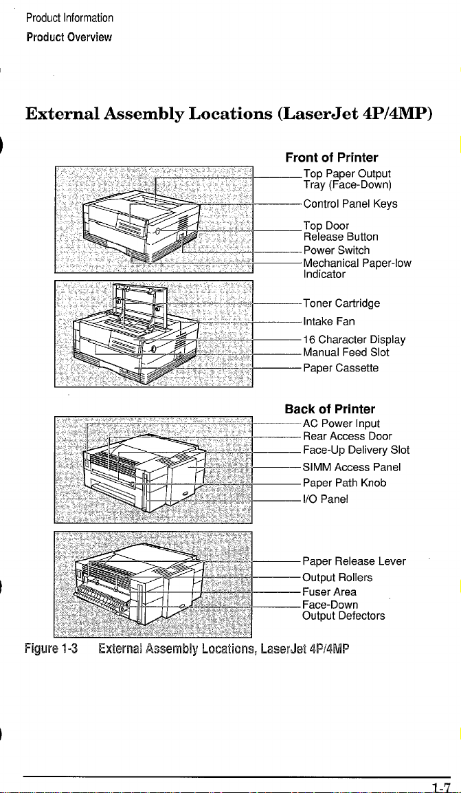
External Assembly Locations (LaserJet 4P/4MP) -1-7
Internal Assembly Locations (all printers) – 1-8
LaserJet 4L Internal Assembly Locations – 1-9
LaserJet 4P Internal Assembly Locations – 1-10
Printer Space Requirements – 2-3
Distributing Toner – 2-6
Attaching the Help Labe”ls (LaserJet 4L/4ML) – 3-6
LaserJet 4L/4ML Front Control Panel – 3-9
LaserJet 4P/4MP Front (;ontrol Panel – 3-12
LaserJet 4P/4MP Menu Map – 3-14
Service Mode Menu Map (LaserJet 4ML/4P/4MP) -3-16
LaserJet 4L Self Test Page – 3-20
LaserJet 4MP Service Mt]de Self Test Page – 3-22
Engine Test Button and Printout (LaserJet 4L) – 3-25
Service Checkpoints – 4-2
Sample 5% Page Coverage – 4-4
Paper Feed Area Jam – 4-9
Clearing Jams from the Toner Cartridge Area – 4-10
Clearing Jams from the l’aper Guide – 4-10
Releasing Paper from the Fusing Assembly – 4-11
Clearing Jams from the Fuser Area – 4-12
Printer Functional Block Diagram – 5-2
DC Controller Loads – 5-3
Top Cover/Toner Cartridge Plunger – 5-6
Power Supply Block Diagram – 5-9
High Voltage Power Timing – 5-11
Formatter Block Diagram – 5-12
EconoMode vs. Regular F’rint – 5-18
Image Formation Block Diagram – 5-22
Photosensitive Drum – 5-23
Page 7
Fig 6-1
Fig 6-2
Fig 6-3
Fig 6-4
Fig 6-5
Fig 6-6
Fig 6-7
Fig 6-8
Fig 6-9
Fig 6-10
Fig 6-11
Fig 6-12
Fig 6-13
Fig 6-14
Fig 6-15
Fig 6-16
Fig 6-17
Fig 6-18
Fig 6-19
Fig 6-20
Fig 6-21
Fig 6-22
Fig 6-23
Fig 6-24
Fig 6-25
Fig 6-26
Fig 6-27
Fig 6-28
Fig 6-29
Fig 6-30
Fig 6-31
Fig 6-32
Fig 6-33
Fig 6-34
Fig 6-35
Fig 6-36
Fig 6-37
Fig 6-38
Fig 6-39
Fig 6-40
Fig 6-41
Fig 6-42
Fig 6-43 Pickup Feed Roller Assembly (bottom view) – 6-48
Fig 6-44 Feeder Guide Assembly – 6-49
Fig 6-45 Small Media Roller Assembly – 6-50
Fig 6-46 Static Eliminator Strip – 6-51
Fig 6-47 Toner Cartridge Lever Assembly – 6-52
Fig 6-48 Top Cover Switch {Plunger Assembly) -6-53
Fig 6-49 Releasing the Side Tabs – 6-.54
Phillips vs. Posidriv Screwdrivers – 6-3
Memory Module (LaserJet 4L) – 6-4
SIMM Access Panel (LaserJet 4P/4MP) – 6-5
Power Access Door (LaserJet 4L/4ML) – 6-6
Printer Cover Screws (Laser,Jet 4L/4ML) – 6-7
Releasing the Printer Cover Rear Tabs – 6-8
Control Panel Connector (LaserJet 4P/4MP) – 6-9
Printer Cover Screws (Laser, Jet 4P/4MP) – 6-10
Cover (LaserJet 4P/4MP) – 6-11
Rear Door – 6-12
Control Panel Assembly (LaserJet 4P/4MP) -6-13
Control Panel RFI Shield (LaserJet 4P/4MP) -6-14
Formatter Shield and PCA – 6-15
DC Controller Connector& Switch Actuator – 6-16
Gear Train Assembly – 6-17
Screw Tightening Sequence Example – 6-18
Main Motor – 6-19
Oblique Roller Assembly – 6-20
Tray Forms Size Guide – 6-21
Paper Cassette Assemblies – 6-22
Laser/Scanner Assembly – 6-23
Fan – 6-24
Power Switch Assembly (LaserJet 4P/4MP) – 6-25
Paper Guide/Roller Assembly – 6-26
Transfer Roller -6-27
Beam-to-Drum Mirror – 6-29
Fusing Assembly – 6-30
Fusing Pressure Plate – 6-31
Upper Fusing Assembly – 6-32
Fuser Delivery Assembly – 6-33
Lower Delivery Roller – 6-34
Lower Delivery Guide and Exit Sensor Flag – 6-35
Fuser Connector Assembly – 6-36
Upper Output Roller Assembly – 6-37
Lower Output Rollers – 6-38
DC Controller Assembly – 6-40
Pickup Feed Roller Solenoid – 6-41
Machine Screw Locations (DC Controller PCA) – 6-43
Metal Backing Plate – 6-44
DC Controller PCA – 6-45
D-Roller – 6-46
Pickup Feed Roller Assembly (side view) – 6-47
Page 8
Fig 6-50 DC Controller/Scanner Connector Location – 6-55
Fig 6-51 Input Paper Sensor Arm -6-56
Fig 7-1 Paper Path and Components – 7-4
Fig 7-2 DC Controller PCA Components – 7-5
Fig 7-3 Top Door/T’oner Cartridge Plunger Assembly – 7-9
Fig 7-4 Engine Test Button and Printout (LJet 4L/4ML) -7-36
Fig 7-5 Defeating the Top Door Plunger (LJet 4P/4MP) – 7-37
Fig 7-6 Defeating the Exit Sensor Flag (LaserJet 4P/4MP) – 7-38
Fig 7-7 Leading Edge Adjustment – 7-43
Fig 7-8 Beam -to-Dru]m Mirror Adjustment – 7-45
Fig 7-9 Repetitive Image Defect Ruler – 7-46
Fig 7-10 Main Wiring Diagram – 7-47
Fig 8-1 Assembly Locations – 8-7
Fig 8-2 Covers and Doors (LaserJet 4L/4ML) – 8-8
Fig 8-3 Covers and Doors (LaserJet 4P/4MP) – 8-10
Fig 8-4 Internal Components 1 – 8-12
Fig 8-5 Internal Components 2 – 8-14
Fig 8-6 Internal Components 3 – 8-16
Fig 8-7 DC Controller Assembly – 8-18
Fig 8-8 Gear Train Plate Assembly – 8-20
Fig 8-9 Paper Cassette (LaserJet 4L/4ML) – 8-21
Fig 8-10 Paper Cassette (LaserJet 4P/4MP) – 8-22
Fig 8-11 Pickup Assemb] y – 8-23
Fig 8-12 Fuser Assembly – 8-24
Fig 8-13 Keyboard Overlay (LaserJet 4P/4MP) – 8-26
Fig B-1 Parallel Cable Pin Assignments – B-2
Fig B-2 Serial Pin-outs DB-25 to DB-9 – B-3
Fig B-3 Serial Pin-outs DB-9 to DB-9 – B-3
Fig B-4 Connecting to END of a LocalTalk Network – B-4
Fig B-5 Connecting to MIDDLE of a LocalTalk Network – B-5
Page 9
Tbl 1-1
Tbl 1-2
Tbl 1-3
Tbl 1-4
Tbl 1-5
Tbl 2-1
Tbl 2-2
Tbl 2-3
Tbl 2-4
Tbl 2-5
Tbl 2-6
Tbl 2-7
Tbl 2-8
Tbl 3-1
Tbl 3-2
Tbl 4-1
Tbl 4-2
Tbl 5-1
Tbl 5-2
Tbl 5-3
Tbl 7-1
Tbl 7-2
Tbl 7-3
Tbl 7-4
Tbl 7-5
Tbl ‘7-6
Tbl 7-7
Tbl ‘7-8
Tbl 7-9
Tbl 7-10 Scanner Error --7-13
Tbl 7-11 WROM Error – 7-14
Tbl 7-12 Engine Error – 7-15
Tbl ‘7-13 Main Motor Error – 7-15
Tbl 7-14 Fan Error – 7-16
Tbl 7-15 Formatter Error – 7-16
Tbl 7-16 NVRAM Error – 7-17
Tbl 7-17 Blank Display – 7-17
Tbl 7-18 Blank (White) Page – 7-24
Tbl 7-19 Black Page -7-25
Tbl 7-20 Faded Print -7-26
Tbl 7-21 Vertical White Stripes – 7-27
Tbl 7-22 Vertical Black I.ines – 7-28
Tbl 7-23 Horizontal Black Lines – 7-28
Printer Dimensions – 1-4
Performance Specifications -1-4
Environmental Specifications – 1-5
Electrical Specifications – 1-5
Related Documentation – 1-19
Current Requirements (Amps) – 2-2
Printer Operating Dimensions – 2-3
Toner Cartridge Environmental Conditions – 2-4
Supported Media Sizes – 2-!3
Selected Paper Specifications – 2-11
Envelope Speciilcations–212
Adhesive Label Specifications – 2-14
Transparency Specifications – 2-15
Front Panel Button Usage --3-11
Menu of Resets (LaserJet 4“P/4MP) – 3-27
Life Expectancy of Consumi~bles – 4-3
Cleaning Printer Components – 4-6
Solenoids – 5-35
Photosensors – 5-35
Print Period Descriptions – 5-40
Paper Out Error -7-7
Paper Jam Error – 7-8
Door Open Error – 7-9
Memory Error – 7-10
Manual Feed – 7-10
Service Error -7-11
Fuser Error --7-12
Fuser Checks – 7-12
Beam Error – 7-13
. .
Page 10
Tbl 7-24 Repetitive Defects – 7-29
Tbl 7-25 Staining -7-30
Tb”l 7-26 Dropout – 7-31
Tbl 7-27 Character Voids – 7-31
Tbl 7-28 Background Scatter – 7-32
Tbl 7-29 Bottom Portion of Page Blank – 7-32
Tbl 7-30 Faulty Registration – 7-33
Tbl 7-31 Smeared Print – 7-34
Tbl 7-32 Image Skew – 7-35
Tbl 7-33 Compressed Print – 7-35
Tbl 7-34 High-Voltage System Checks – 7-41
Tbl 7-35 Causes of Paper Curl – 7-42
Tbl 8-1 Fasteners IJsed in the Printer – 8-4
Tbl 8-2 Covers and Doors (LaserJet 4L/4ML only) – 8-9
Tbl 8-3 Covers and Doors (LaserJet 4P/4MP only) – 8-11
Tbl 8-4 Internal Components 1 – 8-13
Tbl 8-5 Internal Components 2 – 8-15
Tbl 8-6 Internal Components 3 – 8-17
Tbl 8-7 DC Controller Assembly – 8-19
Tbl 8-8 Gear Train Plate Assembly – 8-20
Tbl 8-9 Paper Cassette (LaserJet 4L/4ML) -8-21
Tb[ 8-10 Paper Cassette (LaserJet 4P/4MP) -8-22
Tb~ 8-11 Pickup Assembly – 8-23
Tbl 8-12 Fuser Assembly -8-25
Tb\ 8-13 Keyboard Overlays (Laser,Jet 4P/4MP) – 8-26
Page 11

x
Page 12
Chapter Contents
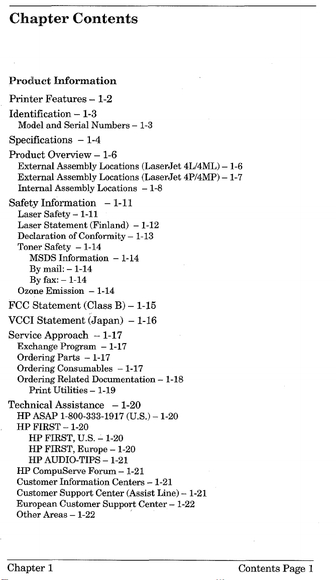
Product Information
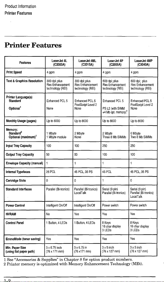
Printer Features – 1-2
Identification – 1-3
Model and Serial Numbers – 1-3
Specifications – 1-4
Product Overview – 1-6
External Assembly Locations (LaserJet 4L/4ML) – 1-6
External Assembly Locations (LaserJet 4P/4MP) – 1-7
Internal Assembly Locations – 1-8
Safety Information – 1-11
Laser Safety – 1-11
Laser Statement (Finland) – 1-12
Declaration of Conformity – 1-13
Toner Safety – 1-14
MSDS Information – 1-14
By mail: – 1-14
By fax: – 1-14
Ozone Emission – 1-14
FCC Statement (Class B) – 1-15
VCCI Statement (Japan) – 1-16
Service Approach – 1-17
Exchange Program – 1-17
Ordering Parts – 1-17
Ordering Consumables – 1-17
Ordering Related Documentation – 1-18
Print Utilities – 1-19
Technical Assistance – 1-20
HP ASAP 1-800-333-1917 (U.S.) – 1-20
HP FIRST -1-20
HP FIRST, U.S. – 1-20
HP FIRST, Europe – 1-20
HP AUDIO-TIPS – 1-21
HP CompuServe Forum – 1-21
Customer Information Centers – 1-21
Customer Support Center (Assist Line) – 1-21
European Customer Support Center – 1-22
Other Areas – 1-22 ‘
Chapter 1
Contents Page 1
Page 13
CI!-mpttwcamtemrts
2 Q@a=ating Rmq@7mflmmfx
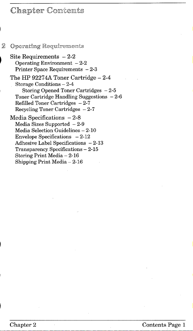
Site Requirements – 2-2
Operating Environment – 2-2
Printer Space Requirements – 2-3
The HP 92274A Toner Cartridge – 2-4
Storage Conditions – 2-4
Storing Opened Toner Cartridges – 2-5
Toner Cartridge Handling Suggestions – 2-6
Refilled Toner Cartridges – 2-7
Recycling Toner Cartridges – 2-7
Media Specifications – 2-8
Media Sizes Supported – 2-9
Media Selection Guidelines – 2-10
Envelope Specifications – 2-12
Adhesive Label Specifications – 2-13
Transparency Specifications – 2-15
Storing Print Media – 2-16
Shipping Print Media – 2-16
Chapter 2
Contents Page 1
Page 14
0&@x5w’ Q3mr&?mts
hs’tdktimoi and Cmfigmlmtilm
Unpacking and Installation – 3-2
A. Choose the best location. – 3-2
B. Unpack the printer. – 3-2
C. Check package contents. – 3-3
D. Install the toner cartridge. – 3-3
E. Load the paper cassette. – 3-4
F. Attach the interface cable(s). – 3-4
G. Attach the power cord. – 3-5
H. Attach the Help Labels (Lase’Jet 4L/4ML only) – 3-6
I. Install Printer Drivers and Utilities (optional) – 3-7
How to Obtain Printer Drivers – 3-7
Using the Printing Software Package – 3-8
Using the Control Panel – 3-9
LaserJet 4L/4ML Control Panel Overview – 3-9
The LaserJet 4L/4ML Lights – 3-10
The LaserJet 4L/4ML Front Panel Button – 3-11
LaserJet 4P/4MP Control Panel Overview – 3-12
LaserJet 4P/4MP Control Panel Display and Lights – 3-13
Service Mode (LaserJet 4ML/4P/4MP) – 3-15
LaserJet 4ML – 3-15
LaserJet 4P/4MP – 3-15
Setting the Page Count (LaserJet 4P/4MP) -3-17
Setting the Cold Reset Default (LaserJet 4P/4MP) -3-18
Other Service Mode Items – 3-18
Printing a Self Test – 3-19
LaserJet 4L/4ML: – 3-19
LaserJet 4P/4MP: – 3-19
The LaserJet 4L Self Test Fields – 3-21
The LaserJet 4ML/4P/4MP Self Test Fields – 3-23
Continuous Self Test – 3-24
LaserJet 4L/4ML: – 3-24
LaserJet 4P/4MP: – 3-24
Engine Test – 3-25
(continued on back)
Chapter 3
Contents Page 1
Page 15
Resetting the Printer – 3-26
LaserJet 41J4ML:– 3-26
LaserJet 4P/4MP: – 3-26
Simple Reset – 3-26
The Menu of Resets – 3-27
The Cold Reset (LaserJet 4ML/4P/4MP) – 3-28
LaserJet 4ML: – 3-28
LaserJet 4P14MP:– 3-28
PJL Software Commands – 3-29
Contents Page 2 Chapter 3
Page 16

chapter CkDntc?nts
4 Maintenancx2
Service Checkpoints – 4-2
Life Expectancy of Consumables – 4-3
Toner Cartridge Life –
Saving Toner with EconoMode – 4-5
Cleaning Printer Components – 4-6
Cleaning Spilled Toner – 4-7
(leafing Paper Jams – 4-8
Paper Jams in the Paper Feed Area – 4-9
Paper Jams Inside The Printer – 4-10
Paper Jams in the Paper Output Area – 4-12
4-4
Chapter 4 Contents Page 1
Page 17

Chapter Contents
5 Functional Overview
Basic Printer Functions – 5-2
DC Controller/Power System – 5-3
Print Engine Control – 5-5
Laser and Scanner Drive – 5-5
Paper Motion Monitoring and Control – 5-5
Top Door/Toner Cartridge Microswitch (SW201) – 5-6
Engine Test MicrosWitch (SW301) -5-7
Motors – 5-7
Power System (on DC Controller PCA) – 5-8
AC Power Distribution – 5-8
DC Power Distribution – 5-8
Overcurrent/Overvoltage Protection – 5-10
Intelligent ON/OFF (LaserJet 41J4ML only) – 5-10
High Voltage Power Distribution – 5-11
Formatter System – 5-12
CPU – 5-13
Read Only Memory (ROM) -5-13
Random Access Memory (RAM) -5-13
Non-Volatile Memory (NVRAM) – 5-14
Parallel Interface – 5-14
High Speed (Yes/No) – 5-14
Advanced Functions (On/Off) – 5-14
Serial I/O (LaserJet 4P/4MP) -5-15
Pacing (Serial Modes of Operation) – 5-15
LocalTalk I/O (LaserJet 4ML/4MP) – 5-15
Control Panel – 5-16
LaserJet 4L/4ML – 5-16
LaserJet 4P/4MP – 5-16
Resolution Enhancement (REt) – 5-17
Print Density Adjustment – 5-17
EconoMode – 5-18
Memory Management – 5-19
Memory Enhancement technology (MEt) – 5-19
Image Adapt (LaserJet 4L/4ML) – 5-20
Page Protect – 5-20
PJL Overview – 5-21
(continued on back)
Chapter 5
Contents Page 1
Page 18
Image Formation System – 5-22
Photosensitive Drum – 5-23
Drum Sensitivity – 5-24
Cleaning Stage – 5-25
Conditioning Stage – 5-26
Writing Stage – 5-27
Developing Stage – 5-29
Transferring Stage – 5-31
Fusing Stage – 5-32
Paper Feed System – 5-33
Paper Movement Overview – 5-34
Solenoids – 5-35
Photosensors – 5-35
Paper Out Sensor (PS2) – 5-35
Input Paper Sensor (PS1) – 5-36
Printing from the Paper Cassette – 5-37
Manual Feed Printing – 5-38
Small Media Rollers (LaserJet 4P/4MP) – 5-38
Paper Jam Detection – 5-39
Power-On Jams – 5-39
Pickup Jams – 5-39
Delay Jams – 5-39
Basic Sequence of Operation – 5-40
Standard Printer Operation – 5-40
General Timing Diagram – 5-41
Contents Page 2
Chapter 5
Page 19
Cx’-?.apbfckmiw?i’Nts
JRmmKmd and W@wmnm?nt
Removal and Replacement Strategy – 6-2
Required Tools – 6-3
User Installable Assemblies – 6-4
Memory Upgrade (LaserJet 4L) – 6-4
Memory/Language SIMMS(LaserJet 4P/4MP) – 6-5
Cover and Doors – 6-6
Power, I/O and Memory Doors (LaserJet 41J4ML) -6-6
Printer Cover (LaserJet 4L/4ML) -6-7
Printer Cover (LaserJet 4P/4MP) -6-9
Rear Door – 6-12
Control Panel (LaserJet 4P/4MP) ~ 6-13
Left Side Assemblies – 6-15
Formatter Shield and PCA – 6-15
Gear Train Assembly – 6-17
Main Motor – 6-19
Front Assemblies – 6-20
Front Oblique Roller Assembly – 6-20
Paper Cassette Assembly – 6-21
Tray Forms Size Guide (LaserJet 4L/4ML) -6-21
Compression Springs – 6-22
Internal Assemblies – 6-23
Laser/Scanner Assembly – 6-23
Fan – 6-24
Power Switch Assembly (LaserJet 4P/4MP only) -6-25
Paper Guide/Top Oblique Roller Assembly – 6-26
Transfer Roller and Guide – 6-27
Transfer Roller Bushings – 6-28
Beam-to-Drum Mirror Assembly – 6-29
‘1
(continued on back)
Chapter 6
Contents Page 1
Page 20
Rear Assemblies – 6-30
Fusing Assembly – 6-30
Fusing Assembly Components – 6-31
Pressure Plate – 6-31
Upper Fusing Assembly
(Teflon Sleeve and Heater Element) -6-32
Pressure Roller – 6-33
Delivery Assembly – 6-33
Lower Delivery Roller – 6-34
Lower Delivery GuidelExit Sensor Flag – 6-35
Connector Assembly (Fuser Entrance Guide) – 6-36
Upper Output Roller Assembly – 6-37
Lower Output Rollers – 6-38
Bottom Assemblies – 6-39
DC Controller Assembly – 6-39
Pickup Solenoid (SL2) – 6-41
DC Controller Fuses – 6-42
High Voltage Connector Assembly – 6-42
DC Controller PCA – 6-43
Pickup Feed D-Roller – 6-46
Pickup Assembly – 6-47
Feeder Guide Assembly and High Voltage Shield – 6-49
Small Media Roller Assembly (LaserJet 4P/4MP) -6-50
Static Eliminator Strip Assembly – 6-51
Toner Cartridge Lever Assembly – 6-52
Top Door Switch (Plunger Assembly) – 6-53
DC Controller/Scanner Connector Assembly -6-54
PS1 Input Paper Sensor Arm – 6-56
Contents Page 2
Chapter 6
Page 21
... -’
TmlldMeshmtintg
Troubleshooting Flowchart – 7-2
Paper Path and Components – 7-4
DC Controller Diagram – 7-5
Printer Error Troubleshooting – 7-6
LaserJet 4L/4ML: – 7-6
LaserJet 4P/4MP: – 7-6
Priority of Errors – 7-7
Recoverable Errors – 7-7
Service Errors – 7-11
LaserJet 4L/4ML – 7-11
LaserJet 4P/4MP – 7-11
Clearable Warnings (LaserJet 4P/4MP) – 7-18
Image Formation Troubleshooting – 7-19
Engine Test – 7-36
Engine Test Button Location – 7-36
Printing an Engine Test - LaserJet 4L/4ML – 7-36
Printing an Engine Test - LaserJet 4P/4MP – 7-37
Half Self Test Functional Check – 7-39
Drum Rotation Functional Check – 7-40
High-Voltage Power Supply Check – 7-41
Paper Curl – 7-42
Adjustment Procedures – 7-43
Leading Edge Adjustment – 7-43
Beam-to-Drum Mirror Adjustment – 7-44
Troubleshooting Tools – 7-46
Repetitive Image Defect Ruler – 7-46
Main Wiring Diagram – 7-47
Chapter 7
Contents Page 1
Page 22
Chapter Contents
$ Parts and Diagrams
How to Use the Part Lists and Diagrams – 8-2
Orderhw Parts – 8-2
Orderin~ Consumables – 8-3
Common Hardware – 8-4
Accessories and Supplies -8-5
Assembly Locations -8-7
Covers and Doors (LaserJet 4L/4ML) -8-8
Covers and Doors (LaserJet 4P/4MP) -8-10
Internal Components 1 – 8-12
Internal Components 2 – 8-14
Internal Components 3-8-16
DC Controller Assembly – 8-18
Gear Train Plate Assembly -8-20
Paper Cassette (LaserJet 4L/4ML) – 8-21
Paper Cassette (LaserJet 4P/4MP) – 8-22
Pickup Assembly – 8-23
Fuser Assembly -8-24
Keyboard Overlay (LaserJet 4P/4MP) – 8-26
Chapter 8
Contents Page 1
Page 23
AppendixA
Parts Index
Page 24
Appendk B
170IMorrnation
Page 25

Page 26

Product Itiormation
Page 27
Product Information
Printer Features
Printer Features
Features
Print Speed
Text &Graphics Resolution 300 dpi;
Printer Language
Stsndard Enhanced PCL5
Optionat
Monthly Usage (pages)
Output Tray Capacity I 50 50
LaserJet 4L
(C2003A)
I
I 4ppm
@JS
Res Enhancement
technology (REt)
None
I Upto6000
*
Standard Interfaces Parallel (13-tronics)
LsaarJet 4ML
I
(C2015A)
300 dpi;plus
Res Enhancement
technology (REt)
Enhanced PCL 5
PostScript Level 2
None
UP tO 8000
1
45 PCL, 35 PS
o
Parallel (8i-tronics)
LocalTalk
600 dpi;plus 600dpi;
Res Enhancement
technology (REt)
Enhanced PCL 5 Enhanced PCL 5
PS L2 (with SIMM
+4 Mb opt memory)’
up to 8000 UPto8000
plus
Res Enhancement
technology (REt)
PostScript Level 2
None
=--l=-
Setial (9 pin) Serial (9 pin)
Parallel (8i-tronics) Parallel (!3-tronics)
LocalTalk
I
Power Control
EconoMode (toner saving)
Min. Paper Size
(using flat paper path)
1bteligentC)n/Ofl
1
Yes
3 x6.75inch
(76x 171mm)
1
See“Accessories&Supplies”in Cha
Intelligent On/Ofl I Power switch lF’owerswitch I
ter
8 foroptionproductnumbers.
2PrintermemoryisoptimizedwithMemoryEnhancementTechnology(MEt).
Page 28
Product Information
Identification
Identification
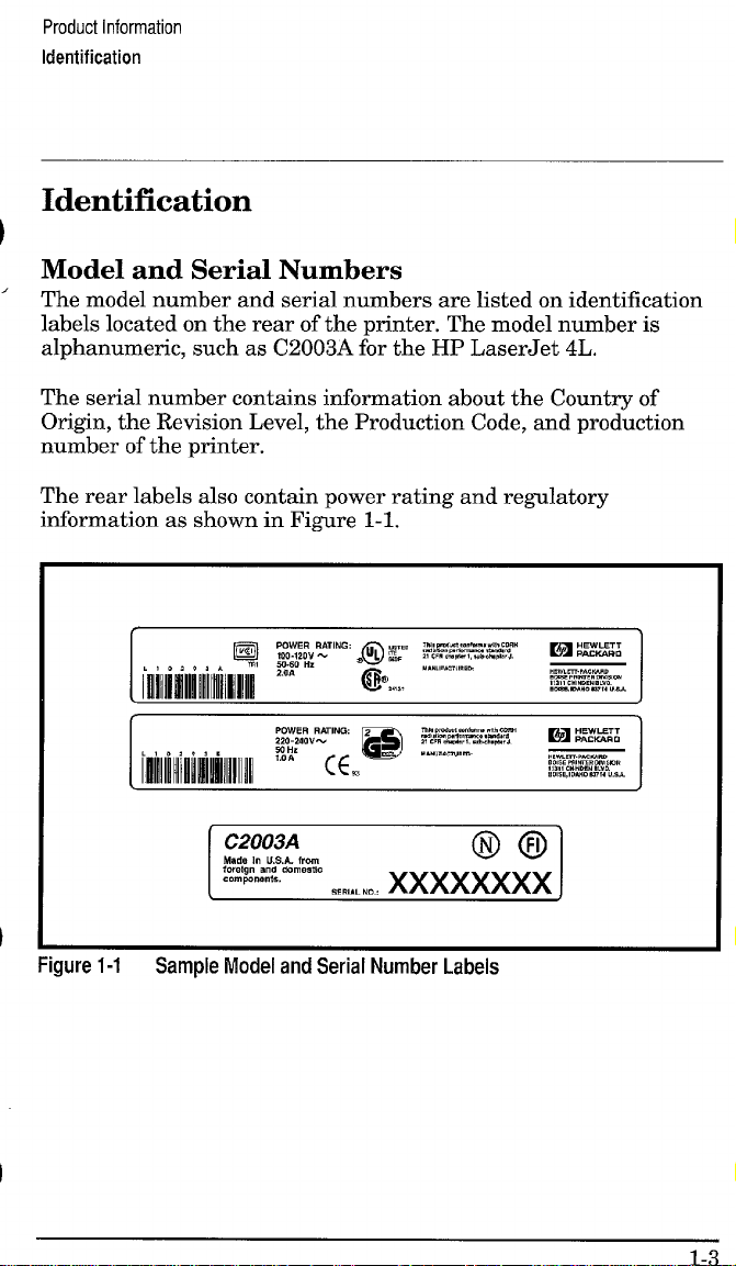
Model and Serial Numbers
The model number and serial numbers are listed on identification
labels located on the rear of the printer. The model number is
alphanumeric, such as C2003A for the HP LaserJet 4L.
The serial number contains information about the Country of
Origin, the Revision Level, the Production Code, and production
number of the printer.
The rear labels also contain power rating and regulatory
information as shown in Figure 1-1.
I
Figure 1-1
Sample Model and Serial Number Labels
I
Page 29

Product Information
Specifications
Specifications
Table 1-1
Width
Depth
Heiaht 116.5 cm (6.5 in.) 118 cm (7 in.)
Table 1-2 Performance Specifications
I
Print Speed * Up to 4 pages per minute
Monthly Usage (Duty Cycle)
Life Expectancy of toner cartridge** Approximately 3000 pages
IFirst Print lApproximately 34 seconds
*Actual speed depends on data complexity and software handling efficiency.
**Toner
Printer Dimensions
Dimension
CATEGORY
Cartridge life can be extended by using EconoMocle.
LaserJet 4L/4ML LaserJet 4P/4MP
(C2003A/C2015A) (C2005A/C2040A)
36 cm (14,25 in.)
137 cm (14.5 in.) 139 cm (15.5 in.)
, 1
I
Up to 8000 pages
40 cm (15.75
SPECIFICATION
in.)
I
I
I
Page 30
Product Information
Specifications
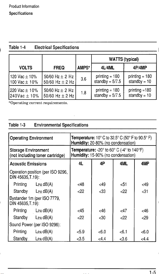
Table 1-4
Electrical Specifications
VOLTS FREQ
120 Vact10%
100 Vac ? 10%
220 Vac f 1O%
240Vac k 10%
*Operating current requirements.
Table 1-3
50/60 Hz k 2 Hz
50/60 Hz? 2 Hz
50/60 Hz+ 2 tiz
50/60 Hz k 2 Hz
Environmental Specifications
Operating Environment
Storage Environment
(not including toner cartridge)
Acoustic Emissions
Operation position (per ISO 9296,
DIN 45635,T.1 9):
Printing
Standby
LPA dB(A)
LPAdB(A)
Bystander 1m (per ISO 7779,
DIN 45635,T.1 9):
Printing
LPA dB(A)
Standby LPA dB(A)
Sound Power (per ISO 9296):
Printing
Standby
LPA dB(A)
LPA dB(A)
WATTS (typical)
AMPS*
4L14ML I 4P14MP
36
,8
“
‘temperature: 10° C to 32.5° C (50° F to90.5° F)
Iumidity: 20-80% (no condensation)
‘temperature: -20° to 60° C (-4° to 140”F)
Iumidity: 15-90% (no condensation)
4L
<48
<22
<45
<22
<5.9
<3.5
4P
<49
<33
<46
<30
<6.0
<4.4
4ML
<51
<22
<47
<22
<6.1
<3.6
4MP
<49
<31
<46
<29
<6.0
<4,4
Page 31

Product Information
Product Overview
Product Overview
External Assembly Locations (LaserJet 4L/4ML)
Figure 1-2
External Assembly Locations, Laserdef 4L/4ML
Page 32
Product Information
Product Overview
External Assembly Locations (LaserJet 4P/4MP)
Page 33

Product Information
Product Overview
Internal Assembly Locations
Figure 1.4 Internal Assembly Locations (all printers)
1, Face-Down Output Rollers
2. Upper Fusing Assembly
3. Laser/Scanner Assembly
4. Primary Charging Roller
5. Beam-to-Drum Mirror
6. Developing Cylinder
7. Toner Cartridge
8. Registration Roller
9. Oblique Rollers
10, Pickup Feed D-Roller
11. Transfer Roller Assembly
12, Photosensitive Drum
13. DC Controller PCA
14. Paper Cassette
15. Fusing Pressure Roller
16. Face-up Delivery Roller
17. Face-Up/Face-Down Deflector
Page 34

Product Information
Product Overview
Fim.me 1-5 shows the location of assemblies visible from the ton of
th; LaserJet 4L printer with the printer cover removed. ‘
~lgure 1-5 LaserJet 4L Internal Assembly Locations
1. Transfer Roller 8. Fusing Assembly
2. Paper Guide/Top Oblique Roller 9. Lower Output Rollers (Face-Down)
3. Front Oblique Roller
4, Switch Actuator
5. Formatter PCA
6. Main Motor
10. Upper Output Rollers (Face-Down)
11. Fan (FM1)
12. Beam-to-Drum Mirror
13. Laser/Scanner Assembly
7. Gear Train Assembly
Page 35
Product Information
Product Overview
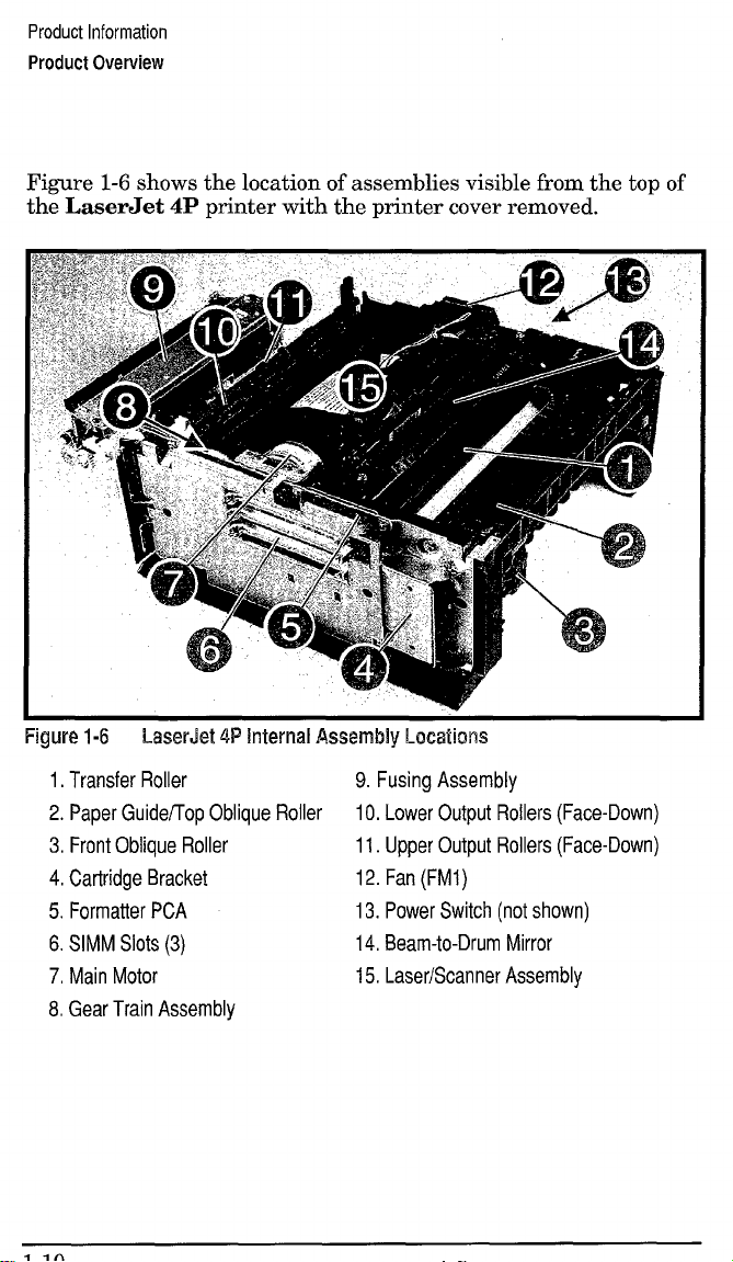
Figure 1-6 shows the location of assemblies visible from the top of
the LaserJet 4P printer with the printer cover removed.
Figure 1-6 LaserJet 4P Internal Assembly Locations
1. Transfer Roller
9. Fusing Assembly
2. Paper Guideflop Oblique Roller 10. Lower Output Rollers (Face-Down)
3. Front Oblique Roller 11. Upper Output Rollers (Face-Down)
4. Cartridge Bracket 12. Fan (FM1)
5. Formatter PCA
6. SIMM Slots (3)
7, Main Motor
13. Power Switch (not shown)
14, Beam-to-Drum Mirror
15, Laser/Scanner Assembly
8. Gear Train Assembly
Page 36

Product Information
Safety Information
Safety Information
Laser Safety
The Center for Devices and Radiological Health (CDRH) of the
U.S. Food and Drug Administration implemented regulations for
laser products manufactured since August 1, 1976. Compliance is
mandatory for products marketed in the United States.
This printer is certified as a “Class 1“ laser product under the U.S.
Department of Health and Human Services (DHHS) Radiation
Performance Standard according to the Radiation Control for
Health and Safety Act of 1968. Since radiation emitted inside this
printer is completely confined within protective housings and
external covers, the laser beam cannot escape during any phase of
normal user operation.
Never operate or service the printer with the
protective cover removed from the
Laser/Scanner Assembly. The reflected beam,
although invisible, can damage your eyes.
1-11
Page 37

Product Information
Safety Information
Laser Statement (Finland)
The following applies to printer operation and servicing in Finland.
LASERTURVALLISUUS
LUOKAN
1 LASERLAITE
KLASS1LASERAPPARAT
HPLaserJet(s)4L,4ML,
luokan 1 laeerlaite. Normaalissa kaytossa kirjoittimen suojakotelointi estaa
lasersateen paasyn laitteen ulkopuolelle.
Kirjoittimen on hyvaksynyt Suomessa laserturvallisuuden osalta
Stikotarkastuskeskus. Laitteen turvallisuusluokka on maaritetty valtioneuvoston
paatoksen N:o 472/1985 ja standardin EN 60825 (1991)
4P &. 4MP Iaserkirjoitin on kayttajan kannalta turvallinen
mukaisesti.
VAROITUS ! Laitteenkayttaminenmuullakuinkayttoohjeessamainitullatavalla
saattaaaltistaakayttajanturvallisuusluokan
lasersateilylle.
1 ylittavalle nakymattomalle
VARNING! Omapparatenanvandspaannatsattw ibruksanvisning
specificerats,kananvandarenutsattasforosynliglaserstr~lning,somoverskrider
griinsenforlaserklass1.
HUOLTOHPLaserJet(s)4L,4ML,4P&4MP-kirjoittimensisalliieiolekayttajan
huollettavissaoleviakohteita.Laitteensaaavataja huoltaaainoastaansen
huoltamiseenkoulutettuhenkilo.Tallaiseksihuoltotoimenpiteeksieikatsota
variainekasetinvaihtamista,paperiradanpuhdistustataimuitakayttajiin
kasikirjassalueteltuja,kayttajantehtavaksitarkoitettujayllapitotoimia,jotka
voidaansuorittaailmanerikoistyokaluja.
VARO ! Mikalikirjoittimensuojakoteloavataan,oletalttiinanakymattomalle
lasersateilyllelaitteenollessatoiminnassa.~a katsosateeseen.
VARNING! Omlaserprinternsskyddsholjeoppnasd5.apparatenari fanktion,
utsattasanvandarenforosynliglaserstr~lning.Betraktaejstr?alen.
Tiedotlaitteessakaytettavanlaserdiodinsateilyominaisuuksista:
Aallonpituus777-795nm
Teho5mW
Luokan
3B laser
Page 38

Product Information
Safety Information
Declaration of Conformity
According to ISO/IEC Guide 22 and EN 45014:
Manufacturer’s Name:
Manufacturer’s Address:
Hewlett-Packard Company
11311 Chinden Boulevard
Boise, Idaho 83714-1021, USA
declares, that the product
Product Name(s):
Model Number(s):
Product Options:
LaserJet 4L/4ML/4P/4MP
C2003A, C2015A, C2005A, C2040A
All
conforms to the following Product Specifications:
Safet~
EN 60950:1988+ A1,A2
IEC 825:1984 + A1:1990 laser class 1
EMC: CISPR-22:1985 / EN 55022:1988 class Bl)
EN 50082-1:1992
IEC 801-2:1991/ prEN55024-2:1992 - 3kV CD, 8 kV AD
IEC 801-3:1984/ prEN55024-3:1991 - 3V/m
IEC 801-4:1988/ prEN55024-4: 1992-1 kV Power lines
Supplementary Information:
The product herewith complies with the requirements of the Low
Voltage Directive 73/23/EEC and the EMC Directive 89/336/EEC.
1)The product was tested in a typical configuration with
Hewlett-Packard Personal Computer and Test Systems.
Office of Quality Manager
Boise, Idaho USA
June 15, 1993
European Contact: Your Local Hewlett-Packard Sales and Service OffIce or
Hewlett-Packard GmbH, Department ZQ / Standards Europe, Herrenberger
Strae 130, D-7030 Bblingen (FAX + 49-7031-14-3143)
1-13
Page 39

Product Information
Safety Information
Toner Safety
Note
MSDS Information
A Material Safety Data Sheet (MSDS) for toner or any other
chemical used in the printer is available through
Hewlett-Packard’s Customer Information Center by either mail or
fax.
By mail:
To obtain an MSDS for the HP 92274A toner cartridges through
the mail, call the Customer Information Center (CIC) at
1-800-752-0900 between 6 A.M. and 5 P.M. Pacific Standard Time.
By fax
To obtain an MSDS for the HP 92274A toner cartridges by fax, call
HP ASAP (Automated Support Access Program) at 1-800-333-1917
and follow the instructions for using the HP FIRST fax service.
Note
In case of toner spills, skin and clothing are best
cleaned by removing as much toner as possible
with a dry tissue, then washing with cold water.
Hot water causes toner to permanently set into
clothing.
See “Technical Assistance” later in this chapter
for more information on the HP FIRST service.
Ozone Emission
These printers do not use high voltage corona wires in the
electrophotographic process, and therefore generate no measurable
ozone gas (03). The printers instead use charging rollers in the
toner cartridge and in the print engine.
Page 40

Product Information
FCC Statement (Class B)
FCC Statement (Class B)
Note: This equipment has been tested and found to comply with
the limits for a Class B digital device, pursuant to part 15 of the
FCC rules. These limits are designed to provide reasonable
protection against harmful interference in a residential
installation. This equipment generates, uses, and can radiate radio
frequency energy and, if not installed and used in accordance with
the instructions, may cause harmful interference to radio
communications. However, there is no guarantee that interference
will not occur in a particular installation. If this equipment does
cause hmful interference to radio or television reception, which
can be determined by turning the equipment off and on, the user is
encouraged to try to correct the interference by one or more of the
following measures:
●
Reorient or relocate the receiving antenna.
●
Increase the separation between the equipment and the receiver.
●
Connect the equipment into an outlet on a circuit different from
that to which the receiver is connected.
●
Consult the dealer or an experienced radio/TV technician for
help.
Any changes or modifications not expressly approved by
Hewlett-Packard could void the user’s authority to operate this
equipment.
Note
Use of a shielded interface cable is required to
comply within the Class B limits in Part 15 of
FCC rules.
1-15
Page 41

Product Information
VCCI Statement (Japan)
VCCI Statement (Japan)
The VCCI statement below is required in Japan. It is similar to the
FCC regulatory statement. -
Page 42

Product Information
Service Approach
Service Approach
Repair of the printer normally begins with use of the printer’s
internal diagnostics in conjunction with the troubleshooting
procedures in Chapter 7. Once a faulty part is located, repair is
accomplished generally by assembly-level replacement of Field
Replaceable Units (FRUS). Some mechanical parts maybe
repaired at the sub-assembly. PCA component replacement is not
supported by HP. Part numbers for all FRUS are located in
Chapter 8 of this manual.
Exchange Program
HP offers remanufactured assemblies for some selected parts.
These are identified in Chapter 8 and can be ordered through HP’s
Parts Direct Ordering, or Parts Center Europe (PCE).
Ordering Parts
Field replaceable part numbers are found in Chapter 8 of this
manual. Replacement parts may be ordered from HP’s Parts Direct
Ordering, or Parts Center Europe (PCE). Adresses and phone
numbers for both organizations are also found in Chapter 8.
Ordering Consumables
Consumables may be ordered directly from Hewlett-Packard. The
phone numbers for ordering consumables are found in Chapter 8.
1-17
Page 43
Product Information
Service Approach
Ordering Related Documentation
Table 1-5 shows where to order related documentation. Phone
numbers for the various sources are:
. PDO (Parts Direct Ordering)
1-S00-227-8164 (U.S. only)
. PCE (Parts Center Europe)
(49 7031) 14-2253.
e HP’s Distribution Center (HPD)
303-353-7650 (U.S.
Ody)
Page 44
Product Information
Service Approach
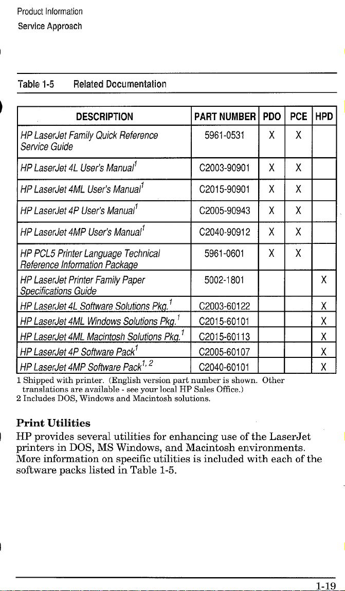
Table 1-5 Relaiecl Documentation
DESCRIPTION
PART NUMBER
HP LaserJet Family Quick Reference
Service Guide
HP LaserJet 4L User’s Manuall
HP LaserJet 4ML User!s Manuali
HP LaserJet 4P User’s Manualf
HP LaserJet 4MP User% Manual’
HP PCL5 Printer Language Technics/
Reference Information Package
HP LaserJet Printer Family Paper
Specifications Guide
HP LaserJet 4L Software Solutions Pkg, f
HP LaserJet 4ML Windows Solutions Pkg. 1
HP LaserJet 4ML Macintosh Solutions Pkg.1
HP LaserJet 4P Software Packl
HP LaserJet 4MP Software Packl’2
Shiu~ed with Drinter. (English version Dart
tra;~lations a;e available --see your loc~l HI
.
z Includes DOS. Windows and Macintosh solutions.
number is shown
Sales Office.)
5961-0531
C2003-90901
C2015-90901
C2005-90943
C2040-90912
5961-0601
5002-1801
C2003-60122
C201 5-60101
C201 5-60113
C2OO5-6O1O7
C2040-60101
PDO IPCE
I
x x
xx
xx
xx
xx
xx
;
1
Other
HPD
x
x
x
x
~
x
Print Utilities
HP provides several utilities for enhancing use of the LaserJet
printers in DOS, MS Windows, and Macintosh environments.
More information on specific utilities is included with each of the
software packs listed in Table 1-5.
1-19
Page 45

Product Information
Technical Assistance
Technical Assistance
HP ASAP 1-800-333-1917 (U. S.)
HP ASAP (Automated Support Access Program) provides free
technical support information 24 hours a day, 7 days a week. The
ASAP system includes HP FIRST and HP AUDIO-TIPS, both
explained below. The ASAP service requires a touch-tone phone.
HP FIRST
HP FIRST (Fax Information Retrieval Support Technology) is a
phone-in fax service providing technical information for HP
LaserJet users as well as service personnel. Receiving a fax
requires a group 3 facsimile machine or fax card. Service-related
information includes:
Service notes (HP Authorized dealers).
Application notes.
Product Data Sheets.
Material Safety Data Sheets (MSDS).
Typeface and accessory information.
Printer support software information.
Toner information.
Driver request form and Software Matrix.
HP FIRST, U.S.
Call the HP ASAP system (1-800-333-1917) and follow the voice
prompts to enter HP FIRST.
HP FIRST, Europe
Call HP FIRST at one of the following numbers:
U.K., 0800-96-02-71 Netherlands, 06-0222420
Belgium (Dutch), 078-111906
Switzerland (German), 155-1527 Austria, 0660-8128
For English service outside the above countries, (31) 20-681-5792
Germany, 0130-810061
Page 46

Product Information
Technical Assistance
HP AUDIO-TIPS
HP AUDIO-TIPS, available within HP ASAP, is an interactive
voice response system providing pre-recorded answers to the
questions most frequently asked by HP LaserJet printer users.
Helpful “System Maps” to the HP AUDIO-TIPS recordings are
available by fax through HP FIRST.
CompuServe members can download a variety of support materials
including product data sheets, software application notes, and
printer drivers for many popular software applications. Members
may also post and reply to questions in an interactive format. To
access the HP Forum, type GO HPPER at any prompt. For more
information, or to join CompuServe, call 1-800-524-3388.
Customer Information Centers
For further technical assistance, service-authorized HP and dealer
service personnel can contact the nearest Hewlett-Packard
Customer Information Center, 1-800-752-0900 in North America.
Customer Support Center (Assist Line)
The HP Customer Support Center, (208-323-2551) is available to
answer technical questions regarding setup, configuration,
installation and operation of HP printers in the PC and Macintosh
environments. The CSC Assist Line is available weekdays from
7AM to 6 PM Mountain Time (Wednesdays until 4 PM).
Questions relating to operating systems such as MS-DOS and
UNIX, your network conjuration, or network operating system
cannot be answered by the Center and should be referred to your
authorized reseller.
1-21
Page 47

Product Information
Technical Assistance
European Customer Support Center
The HP European Customer Support Center, located in
Amsterdam, Holland, is open from 8:30 am to 6:00 pm central
European time (Wednesdays until 4:00 pm). Multilingual customer
support representatives can answer technical questions similar to
the U.S. CSC, described on the previous page. This service is
available at no charge for a period equivalent to the original HP
hardware warranty period.
Each time you call the HP European Customer Support Center,
you will be required to provide the printer’s serial number and
original date of purchase.
To receive a fax listing the supported languages on a countries’
phone number, call HP FIRST (refer to “HP FIRST,” earlier in this
section). You can also call the nearest HP sales and service office to
obtain the telephone number for the Center. The Center features
automated call-routing technology, so you will receive faster
service if calling from a touchtone phone or tone dialer.
Other Areas
Outside of North America and Europe, contact your local HP sales
office for assistance in obtaining technical support.
Page 48

2
=.~
Operating Requirements
Page 49

Operating Requirements
SiteRequirements
Site Requirements
Operating Environment
The environmental specifications listed in the “Specifications”
section of Chapter 1 must be maintained to ensure the proper
operation of this printer. Consider the following points before
installing the printer:
Install in a well-ventilated, dust-free area. (Excess dust or
smoke will contaminate the printer’s Beam-to-Drum mirror,
affecting print quality. )
Install on a hard, flat and continuous surface, with all four
printer feet level. Do not install on carpet or other soft surfaces.
Ensure adequate power supply circuitry. Printer current
requirements can be found under “Specifications,” in Chapter 1.
Lighting Flicker: In an effort to reduce energy consumption,
the fuser is turned on only when needed during printing.
During standby mode, the fuser is not kept warm. When the
printer is installed in a home, the instant-on fuser may cause
some house lights to flicker when printing. This phenomenon is
seen in many instant-on products, such as copiers, and will NOT
affect printing, nor will it harm the electrical system in any way.
To reduce a flicker effect, plug the printer into a different outlet
that may be on a separate circuit, or try fluorescent lighting. If
possible, add to the room’s natural lighting. (Surge suppressers
will not prevent flickering lights.)
Install where there is stable temperature and humidity,
with no abrupt changes (away from water sources, humidifiers,
air conditioners, refrigerators, or other major appliances).
Install away from direct sunlight, open flames, or ammonia
fumes. If the printer is placed near a window, make sure the
window has a curtain or blind to block any direct sunlight.
Install with enough space around the printer for proper
access and ventilation (see Figure 2-l).
Page 50

Operating Requirements
Site Requirements
Printer Space Requirements
A
.............
;...................
‘ ~m“~‘1
,.,
,--,’
. . ,------------- ------
F.-. m ---- .
Hgwe z--l
-i-able 2-1 Printer Operating Dimensions
Operating
Dimensions
A (l-m)))
El(Dqm)
C (Width)
D (Rear Dow) I 2 inches (5 cm)
E (Height - Top
Door Cqoxw))
wmer space ~equ~remenls
LaserJet 4L/4ML
I
I 14 inches (35.5cm)
14.5 inches (37 cm)
14.25 inches (36 cm) 15,75 inches (40 cm)
13 inches (33 cm) 14 inches (35 cm)
I
*j
F
B
;..;
~
~,
-----””----------”?
\
‘i \
\
‘,‘,;,
\
II
I
I 15 inches (38 cm)
I 2 inches (5 cm)
c
-“==4
LaserJet 4P/4MP
I
15.5 inches (39 cm)
I
I
2-3
Page 51

Operating Requirements
HP 92274A Toner Cartridge
The
The HP 92274A Toner Cartridge
Toner cartridges contain components which are sensitive to light,
temperature, and humidity. Follow the recommendations in this
section to ensure the highest quality and longest life of HP toner
cartridges.
Table 2-2 Toner Cartridge Environmental Conditions
1 1 I
CATEGORY
Operating
Storage -20° to 40° c
I TEMPERATURE I HUMIDITY
10° to 32,Y c
tO85% RH
35
(50° to 90.5° F)
15 to 90% RH
(-4° to 104° F)
I
Storage Conditions
The toner cartridge is affected by its environment. Packaging
protects the toner cartridge from light and increases its storage
life. It is important to store the cartridge in its original packaging
until the cartridge is ready to be installed in the printer.
When storing the toner cartridge in a warehouse or work area,
make sure the storage place meets the conditions specified in
Table 2-2.
Note
The expiration date of the toner cartridge is
stamped on the cartridge box. This date allows
for up to 2V2 years after manufacture.
Page 52

Operating Requirements
The 1+ 92274A Toner Cartridge
Storing Opened Toner Cartridges
Because the cartridge does not have a shutter to cover the laser
beam access slot, it should be kept inside the printer until empty.
Toner cartridges which have had the toner sealing tape removed
are also more vulnerable to environmental extremes (such as high
humidity).
If the toner cartridge must be removed from the printer, always
store the cartridge:
Inside the protective bag in which it was originally packaged.
In a dark cabinet, away from direct sunlight.
Correct side up and in a horizontal position (not standing on
end).
In a temperature between 10° and 35° C (50° -95° F).
Away from ammonia or other organic solvent fumes.
CAUTION
Never ship the printer with a toner cartridge
installed. Excessive vibration during shipping
can cause toner to leak, contaminating the
printer.
Never expose the toner cartridge to direct
sunlight, or to room light for more than a few
minutes. Bright light and direct sunlight can
permanently damage a toner cartridge.
2-5
Page 53

Operating Requirements
HP 92274A Toner Cartridge
The
Toner Cartridge Handling Suggestions
● Before installing a cartridge, distribute the toner evenly by
rotating the cartridge back and forth five to six times (see
Figure 2-2). Repeat this action when toner begins to run low.
Figure 2-2
●
Do not touch the sutiace of the photosensitive drum in the
cartridge. Protect the drum from light and contamination.
●
Do not disassemble or refill a toner cartridge,
●
Do not expose the cartridge to unnecessary vibrations or shock.
●
Do not expose the photosensitive drum to strong light. White
areas on the page may indicate that the drum has been exposed
to light for too long. If white areas appear, stop the printer and
wait a few minutes. This process should eliminate most
defective images, If not, the toner cartridge maybe placed in a
dark environment for an extended period of time, which may
restore some life to the drum.
●
Never manually rotate the drum, especially in the reverse
direction; internal damage and toner spills may result.
2-6
Distributing Toner
●
●
Page 54

Operating Requirements
The W 92274.4 Toner Cartridge
Refilled Toner Cartridges
While Hewlett-Packard does not prohibit the use of refilled toner
cartridges during the warranty period or while under a
maintenance contract, we do not recommend their use. The
reasons for this are:
Hewlett-Packard has no control or process to ensure that a
refilled toner cartridge functions at the high level of reliability
of a new HP LaserJet toner cartridge. Hewlett-Packard also
cannot predict what the long term reliability effect on the
printer is from using different toner formulations found in
refilled cartridges.
Hewlett-Packard has no control over the actual print quality of
a refilled toner cartridge. The print quality of HP LaserJet toner
cartridges influences the customer’s perception of the printer.
Re~airs resultimz from the use of refilled toner cartridges are
no{ covered und& the HP warranty or maintenance contract.
Recycling Toner Cartridges
In order to reduce the amount of plastics and other wastes
entering our landfllls, Hewlett-Packard has established a program
for recycling used toner cartridges. Parts that do not wear are
re-used in manufacture of new cartridges. Plastic and other
materials are recycled. HP pays the shipping costs. In addition, a
one dollar donation is shared by the Nature Conservancy and the
National Wildlife Federation for each cartridge returned under
this program. To join this recycling effort, follow the instructions
included inside each toner cartridge box.
2-7
Page 55

Operating Requirements
Media Specifications
Media Specifications
Several types of print media can be used with HP LaserJet
printers, provided the media specifications are met, Using media
that does not meet the specifications listed in this section may
increase the incidence of paper jams, cause premature printer
wear, and contribute to repair costs.
Note
It is possible that print media can meet all of the general
specifications listed and still not print satisfactorily because of the
printing environment or other variables over which
Hewlett-Packard has no control.
Hewlett-Packard neither warrants nor recommends the use of any
particular media brand. Properties are subject to change by
manufacturers and HP has no control over such changes. The
operator should test particular media prior to large purchases.
All media should be stable at the 392° F / 200° C temperatures
encountered in the printer’s fusing process.
CAUTION
More detailed media specifications are available
in the HP LaserJet Printer Family Paper
Specification Guide, part number 5002-1801. To
order additional copies, refer to “Ordering
Related Documentation” in Chapter 1.
Use ordy media recommended for use in laser
printers. Printer damage resulting from use of
incompatible media will not be covered by HP
warranty or service agreements.
2-8
Page 56

Operating Requirements
Media Specificatkms
Media Sizes Supported
The following media sizes are supported by the printer’s paper
cassette and manual feed slot.
-i-able2-3
Minimum size:*
3 x 7.5 in. (76x 190 mm)
3x5in. (76x 127mm)
Letter, 8.5 x 11 in. (216x279 mm)
Legal, 8.5 x 14 in. (216x 356 mm)
IExec, 7.25 x 10.5 in. (184x 267 mm) I X I X
A4, 210 x 297 mm (8,27 x 11.69 in.)
Envelopes:
Com-10, 4.1 x9.5 in. (105 x241 mm)
Monarch, 3.87 x 7.5 in. (98x 191 mm)
DL, 110 x220 mm (4.3 x 8.6 in,)
C5, 162x 229 mm (6.4 x 9 in.)
Use the “flat paper path” only (manual feed and rear outpu
“
SupportedMediaS3zes
Sizes
LaserJet 4L/4ML
-
x
-1-
X1X
x x
LaserJet 4P/4MP
Universal Manual
Cassette Feed
7
Y
x
+=
r
r
r
r
x x
x
X1X
x
r
r
x
x
Page 57

Operating Requirements
Media Specifications
Media Selection Guidelines
To achieve the best possible print quality and avoid paper jams,
follow these guidelines for selecting paper:
Use only high quality, copier grade paper. Avoid paper with
embossed lettering, perforations, or texture that is too smooth
or too rough.
Colored paper should be of the same high quality as white
photocopy paper. The pigments must withstand the printer’s
fusing temperature of 392° F (200° C) for 0.1 second without
deterioration. Do not use paper with a colored coating that was
added after the paper was produced.
Pre-printed forms must be printed with non-flammable,
heat-resistant inks that do not melt, vaporize, or release
hazardous emissions when subject to the printer’s
approximately 392° F (200° C) fusing temperature for
0.1 second.
Always test a small sample of a new print media before
purchasing large quantities.
Give a copy of the table on the next page to your paper vendor to
ensure that the paper you purchase meets the specifications for
this printer. More detailed specifications are in the HP LaserJet
Printer Family Paper Specification Guide, HP Part No.
5002-1801. (See “Ordering Related Documentation” in
Chapter 1.)
Page 58

Operating Requirements
Media Specifications
Basis Weight Paper Cassette: 16 to 28 pound (60 to 105 g/m2).
Manual Feed Slot: 16 to 36 pound (60 to 135 g/m2).*
Finishing Precision
Cut sheet to within 0.3 inch (0.8 mm) of nominal, 0.20°
square.
Furnish (Composition) 100% chemical wood pulp and/or cotton fiber.
Grain Long grain.
Moisture Content
4,7 *I% by weight.
Packaging Polylaminated moisture proof ream wrap.
Smoothness 100 to 250 (Sheffield)*
LaserJet 4P/4MP only Heavier paper stock, in the range of 36 to 42 pound
*
(135 to 158 gid) may be used, but must use the “flat paper path” (manual
feed, rear output) and have a Sheffield smoothness rating not greater than 180.
~~~~~
The “flat paper patlf (manual feed slot and rear
face-up delivery door) is recommended for
envelopes, overhead transparencies, and labels.
2-11
Page 59

Operating Requirements
Media Specifications
Envelope Specifications
Choose envelopes that are well-constructed. They should lay flat
and be sharply creased. They should not be wrinkled, nicked, or
otherwise damaged. Envelopes with a peel-off adhesive strip, or
more than one fold-over flap to seal, must use adhesives
compatible with the heat and pressure of the printer’s fusing
process. When printing envelopes, always use the “flat paper path”
~manual feed siot
and the rear face-up delivery door).
CAUTION
TaMe 2-5
Paper Paper used for envelope construction must meet the
Basis Weight
Caliper
Curl (Pre-printed) Envelopes must lay flat with no more than 0.2 in. (5 mm)
Finishing Envelopes must not have any adhesive exposed to the
Furnish (Composition) 1100% chemical wood pulp and/or cotton fiber.
Fusing Compatibility Must not scorch, melt, offset, or release hazardous
Grain Long grain.
Moisture Content
Smoothness 1100 to 250 (Sheffield)
Envelope Specifications
To prevent severe printer damage, do not use
envelopes having windows, clasps, snaps, or
synthetic materials.
requirements in the table under “Media Selection
Guidelines.”
20 to 24 pound (75 to 90 g/m2), single thickness
3.3 to 5.5 roils (0.084 to 0.14 mm), single thickness
curl across the entire surface.
printer. They must be folded accurately, within f 0.04”
(1 mm). There must be no more than two thicknesses of
paper anywhere along the leading edge. All folds must be
well scored and sharply creased, and construction must be
tight (not baggy). Envelopes must not be stuck together
with excess seam sum.
emissions when heated to 392° F (20V C) for 0.1 second,
4.7 +1% bv weiaht.
I
I
I
Page 60

Operating Requirements
Specifications
Media
Adhesive Label Specifications
Use the following guidelines when selecting labels:
The top sheet (printing surface) must be of copier quality and
provide good toner adhesion.
The carrier sheet (backing sheet) must be compatible with the
temperatures and pressure of the fusing process, and must be
coated for easy release of the top sheet.
The adhesive must be stable at the 392° F (200° C)
temperatures encountered for 0.1 second in the printer’s fusing
process, and must not produce emissions that exceed exposure
levels or threshold limits established by OSHA and other safety
agencies. Adhesives must not come into direct contact with any
part of the printer.
Labels must be arranged on the carrier sheet so that any
exposed spaces run lengthwise down the sheet. Using label
stock with spaces between the horizontal rows of labels can
often result in labels peeling off during printing, causing serious
jamming and possible printer damage.
wide selection of suitable labels is available through
Hewlett-Packard. A list of available sizes is in the H“PLaserJet
Printer Family Paper Specification Guide, HP Part No. 5002-1801.
See Chapter 1 for ordering information, or contact your local
authorized HP dealer.
CAUTION -
Do not attempt to print on label sheets after any
of the labels have been removed from the sheet.
Damage to the printer may result.
2-13
Page 61

Operating Requirements
Media Specifications
Adhesive Must not be on any external surfaces of the label
before, during or after printing. Label construction
and die-cutting must not allow labels to peel off
during transport, printing, or fusing.
Caliper
Curl
Must not exceed 0.007 in. (0,1 9 mm)
In ream: flat within 0,2 in, (5 mm)
Finishing Precision Cut sheet within 0.031 in. (0.79 mm) of nominal
and 0.20° square.
Fusing Compatibility
All adhesives, carrier sheets, top sheets, and other
materials used in label construction must be
compatible with the heat and pressure of the fusing
iprocess, Materials must not discolor, melt, offset,
or release hazardous emissions when heated to
392° F (20V C) for 0.1 second,
Packaging
Moisture proof wrap to preserve properties.
—
The “flat paper path” (manual feed slot and rear
face-up delivery door) is recommended for
printing adhesive labels.
Page 62

Transparency Specifications
Overhead transparencies used in HP LaserJet printers must be
able to withstand the 392° F (200° C) temperatures encountered in
the printer’s fusing process for 0.1 second. Suitable transparency
film is available through Hewlett-Packard. Refer to Chapter 3 of
the HP LaserJet Printer Family Paper Specification Guide, HP
Part No. 5002-1801 for details.
Caliper 13.9 to 4.3 roils (0.100 to 0.110 mm)
Cutting Angle
Finishing precision Cut sheet to within 0.03 in. (0.8 mm) of nominal
Fusing Compatibility Overhead transparency material must be
The “flat paper pat~ (manual feed slot and rear
face-up delivery door) is recommended for
printing transparencies.
90° * 0.2°
and t 0.2° of square.
compatible with the heat and pressure of the fusing
process. Materials must not discolor, melt, offset
material, or release hazardous emissions when
heated to 392° F (200° C) for 0,1 second.
2-15
Page 63

Operating Requirements
Media Specifications
Storing Print Media
Follow these guidelines when stacking and storing print media:
Store paper in its ream wrapper until ready to use.
DO NOT store cartons or reams directly on the floo~ place
cartons on a pallet or on shelves.
DO NOT store individual reams in a manner that causes them
to curl or warp along the edges.
Re-wrap partially used packages of media before storing.
DO NOT stack more than six cartons on top of each other.
Stack each carton squarely on top of the one underneath.
Stack each carton upright.
DO NOT place anything on top of media, regardless of whether
the paper is packaged or unpackaged.
Store envelopes in a protective box to avoid damaging the
envelope edges.
Keep stored media away from temperature and humidity
extremes.
DO NOT store printed documents in vinyl folders (which may
contain plasticizers) or expose the documents to petroleum
based solvents.
Shipping Print Media
When shipping print media through different environments,
plastic wrap all cartons on the shipping pallet. When shipping
media across bodies of water, wrap individual cartons as well.
Packaging must protect the media from physical damage.
Page 64

Installation and
Configuration
Page 65

Installation and Configuration
Unpacking and Installation
Unpacking and Installation
Before unpacking the printer, inspect the shipping container for
signs of physical damage. Since a damaged shipping box is an
indication of improper handling during shipping, the printer may
also be damaged.
Note
If the shipping container has any sign of
damage, unpack and power the printer ON with
the carrier’s agent present. If the printer
appears damaged or fails self test, do not
accept it.
A. Choose the best location.
Verify that the printer location meets all requirements listed in
Chapter 2.
B. Unpack the printer.
Remove the power cord, the manuals, and the toner package.
1.
Remove the printer from its box.
2.
Remove the outer packing material from the printer.
3.
Open the printer top door by pressing the door release button
4.
on the right side of the printer (see Chapter 1, Figure 1-2 or 1-3
for location).
Pull out the paper cassette.
5.
Remove the packing spacers from the inside of printer (2 on the
6.
Transfer Roller) and from the paper cassette (2).
.
Page 66

Installation and Configuration
Wy3acking and installation
C. Check package contents.
Nate
If any of the package contents are missing or
damaged, contact your HP dealer immediately.
The package should include the following:
● Printer.
. Power cord.
. Software Solutions package.
● User’s Manual.
● Toner cartridge.
Note
D. Install the
1.
Press the top door release button to open its top door.
2.
Remove toner cartridge from its box and cut it open. Save the
Interface cables are sold separately. Refer to
Chapter 8 for part numbers.
toner cartridge.
packing materials for possible cartridge storage.
Shake the cartridge vigorously to distribute the toner evenly
3.
inside the cartridge (see Figure 2-2 in Chapter 2).
4.
Grasp the toner sealing tape tab on the right side of the
cartridge. Pull firmly to remove the strip of sealing tape.
5.
Grasp the plastic cartridge body (not the metal shutter
linkage), and slide the cartridge into the printer, pushing it
firmly into place. Close the top door.
—
3-3
Page 67

Installation and Configuration
Llnpacking and Installation
E. Load the paper cassette.
1. Pull out the paper cassette located at the lower front of printer
and load approximately 100 sheets (4L/4ML) or 250 sheets
(4P/4MP) of paper. The rear of the stack should fit loosely under
the two backstops at the rear of the paper cassette.
2. Insert the front corner of the paper stack under the metal clip
at the front of the cassette.
Note
3. Resting the paper cassette on a flat surface, slide it into the
printer.
Failure to insert the paper under the metal clip
will cause skewing or paper jams.
F. Attach the interface cable(s).
1. Open the 1/0 Door on the printer’s left rear side (LaserJet
4L/4ML only). Attach the 1/0 cable securely to the printer.
Note
LaserJet 41J4ML: Align the cable with
2.
the 1/0 Door.
Attach the I/O cable to the computer.
3.
Failure to attach the cable securely may result
in an 1/0 error.
the cable hole and close
Page 68

Installation and Configuration
LJnpwking and
hsbllattm
G. Attach the power cord.
LaserJet 4L/4ML: Open the Power Door at the right rear of the
1.
printer by pressing on the back end of the door and swinging it
outward.
2.
Connect the power cord. On the LaserJet 4P/4MP, turn on the
power switch on the right side of the printer.
All front panel lights briefly illuminate, then the green Ready
light comes on. (LaserJet 4P/4MP: There is a brief self test
period before the Ready and the On Line lights are illuminated
and the display reads %3 FZIXW.)
LaserJet 4L/4ML: Align the power cord with the hole at the
3.
rear of the door and close the Power Door.
4.
LaserJet 4L/4ML: Briefly press the front panel button to
generate a self test and verify that the printer is working.
LaserJet 4P/4MP: Press the - key, then Menu
repeatedly until “%;;;T !%+:!..!appears. Then press _ once to
display SZL.FT’zx-~.Press_ to print a self test.
Id ~ J.~ Refer to the section “Printin~ a Self Test.” later
U.JW L=
in this chapter, for a detaile~ description’ of self
test information.
~y~~
Power On/OfX The LaserJet 4P/4MP uses a
conventional on/off power switch. The LaserJet
4L and 4ML printers do not have a power,
switch, but use Intelligent On/Off sensing
instead. (See “Intelligent On/Off in Chapter 5.)
Page 69

Installation and Configuration
Unpacking and installation
H. Attach the Help Labels (L-erJet 4~4ML onlY)
Packaged with the User’s Manual is a sheet of help labels. These
labels explain the meanings of the front control panel lights.
Attach the large help label to the inside of the printer’s top door,
and the small label next to the front panel lights, as shown in
Figure 3-1.
Figure 3-1
3-6
Attaching the Help Labels (LaserJet 4L/LMUW
Page 70

I. Install Printer Drivers and Utilities (optional)
Printer drivers are specialized programs designed to allow specific
software applications to function with the HP LaserJet printers.
Printer utilities include such things as the HP Explorer program
modules, which enhance the usability of the printer and provide
convenient access to printer features outside of specific software
applications.
How to Obtain Printer Drivers
First, check the software’s printer selection feature to see if the
printer is listed among the available printers. If it is not, run the
software’s SETUP or INSTALL program to install a “ptinter
driver” or “printer file” for the printer.
Here are some ways to obtain printer drivers and Software
Application Notes for HP LaserJet printers:
● Check the Printing Software package to see if it includes a driver ‘
for your software.
. Order an updated driver from the software vendor.
. Call Hewlett-Packard at 303-353-7650.
. Obtain a driver request form by fax through HP FIRST
(call 1-800-333-1917).
. Download a driver through CompuServe’s HP Forum. To sign up
for CompuServe, call 1-800-848-8199.
,,.,.., _
J’., .-;
While waiting for a specific HP LaserJet printer
driver, you can substitute a similar printer
driver (such as a driver for the HP LaserJet III,
111P,or 4 printer), These substitute drivers will
allow you to use the printer, but they do not
support all of the printer’s features.
Page 71

Installation and Configuration
Unpacking and k“istallaiion
Using the Printing Software Package
The Printing Software package supplied with the printer provides
many useful programs and utilities, including:
Printer drivers for several popular software applications.
Utilities for automatically copying printer drivers onto your
hard disk.
Software Application Notes for the above applications.
The HP Explorer utilities, including
. A setup program which installs other HP Explorer modules
and automatically updates the computer’s AUTOEXEC.BAT
and CONFIG. SYS files. Use the setup program to add or
delete any of HP Explorer’s utilities at any time.
. The HP Explorer Remote Control Panel allows changes to
printer settings from the computer’s screen. It supplements
the software’s printer support to permit complete control over
the printer’s features.
● The HP Explorer Status Monitor is a “Terminate-and-Stay-
Resident” (TSR) program that automatically displays
messages from the printer on the computer’s screen whenever
the printer’s status changes.
. The HP Explorer Travel Guide is a guide to the printer’s
features. It also serves as an on-line help utility when using
other HP Explorer modules.
Page 72

Installation and Configuration
L/sing M Cbi’m91 FJWEd
Using the Control Panel
LaserJet 4L/4ML Control Panel Overview
The HP LaserJet 4L/4ML printer’s front control panel consists of 4
status lights and a front panel button situated on top of the printer.
-’ Front Panel
Aw%.. ~
jwe 3-2
LaserJet4L/4ML
Front Ckmtrd Panel
3-9
Page 73

Installation and Configuration
The LaserJet 4L/4ML Lights
The LED lights provide a quick way to check the printer’s status.
Ready (Green)
STEADY: The printer is ready to print a job from the paper
cassette,
BLINKING: If this light is blinking and the Data light is on steadily,
the printer is receiving or processing data,
Data (Green)
STEADY: [f the Data light is on steadily and the Ready light is
blinking, the printer is receiving or processing data. If the Data
light and the Ready light are both on steadily, there is unprinted
data still in the printer. Briefly press the front panel button to print
the remaining data.
BLINKING: The printer is in Manual Feed mode, Either insert a
sheet of paper into the manual feed slot, or press the front panel
button briefly to print from the paper cassette instead.
Paper (Amber)
STEADY: The paper cassette is empty or missing, Add more
paper.
BLINKING: There is a paper jam. Jam locations include the paper
cassette, under the toner cartridge, or inside the printer’s rear
access door. See Chapter 4 for clearing paper jams.
Error (Amber)
STEADY: The printer’s top door is open or the toner cartridge is
either missing or not installed correctly. To correct the problem,
make sure the toner cartridge is installed completely and close the
top cover until it snaps shu~
BLINKING: The page is too complex. Press the front panel button
to continue printing. There maybe some data loss on the page.
Try setting Page Protect to On or Auto in the Printer Memory
category of the HP Explorer Remote Control panel. If the page still
doesn’t print correctly, you may need to install the optional printer
memory.
Page 74
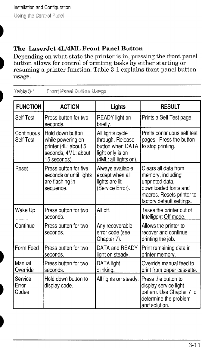
The LaserJet 4L/4ML Front Panel Button
Depending on what state the printer is in, pressing the front panel
button allows for control of printing tasks by either starting or
resuming a printer function. Table 3-1 explains front panel button
usage.
FUNCTION I
Self Test
Continuous
Self Test
Reset
Wake Up Press button for two
Continue Press button for two
ACTION
Press button for two
seconds.
Hold down button
while powering on
printer (4L: about 5
seconds, 4ML: about
15 seconds).
Press button for five
seconds or until lights
are flashing in
sequence.
seconds.
seconds,
F
Form Feed Press button for two
seconds,
Manual
Override seconds.
Service Hold down button to
Error
Codes
Press button for two
display code.
I Liahts
READY light on
briefly.
All lights cycle Prints continuous self tesi
through. Release
button when DATA
light only is on
(4ML: all lights on).
Always available
except when all memory, including
lights are lit
(Service Error). downloaded fonts and
All off.
Any recoverable
error code (see
Chapter 7). printing the iob.
DATA and READY
light on steady,
DATA light
blinking. print from paper cassette.
All lights on steady.
I
Prints a Self Test page,
pages. Press the button
to stop printing.
Clears all data from
unprinted data,
macros, Resets printer to
factory default settings.
Takes the printer out of
Intelligent Off mode.
Allows the printer to
recover and continue
Print remaining data in
printer memory.
Override manual feed to
Press the button to
display service light
pattern. Use Chapter 7 to
determine the problem
and solution.
RESULT
3-11
Page 75

Installation and Configuration
Using the Control F%nei
LaserJet 4P/4MP Control Panel Overview
The HP LaserJet 4P/4MP printer’s front control ~anel consists of a
16 character backlit LCD display, an 8 key contr;l panel, and 4
LED status lights situated on top of the printer.
To access a primary key function (such as On Line, Form Feed, or
Menu) just press the appropriate key. To access secondary key
functions (Reset, EconoMode and -), use the_ key. For
example, to access the “reset” function of the ~ key,
press _ and ~ simultaneously.
igure 3-3 LaserJet 41Y4MP Front Control Panel
Page 76

Installation and Configuration
using it%?Cmml
LaserJet 4P/4MP Control Panel Display and Lights
The printer’s control panel has a 16 character backlit LCD
message display area and four LED status indicator lights. A
complete list of display panel messages is in Chapter 7. The
following describes the functions of the four lights.
Onfine
E
Panel
Ready Light
ON STEADY: There are no error conditions detected. The printer
can only receive a print job when this light as well as the On Line
light are on.
BLINKING: The printer is receiving or processing data. Do not
take off line or switch power off until the light stops blinking.
OFF: The printer is not ready to print. Check the display panel for
a message.
On Line Light
ON STEADY: The printer is ready to receive and process data,
BLINKING: The printer is transitioning from the On Line to Off Line
status.
OFF: The printer is off line (not ready to receive data). Other
control panel keys can now be accessed.
l==+
w
I
item
Ecw@70dc
I Ir
n
Form Feed Light
ON STEADY: There is unprinted data still in the print buffer.
Press - to take the printer off line, then press
~ to print the remaining data,
BLINKING: Buffered data is being printed,
OFF: No buffered data is in the printer.
I
EconoMode Light
ON STEADY: EconoMode is on. This reduces the amount of
toner used on the page. NOTE: Software can override this
selection, even while the EconoMode light is ON.
OFF: EconoMode is off. To turn EconoMode on, press to take the printer off line, then hold down_ while pressing
the EconoMode key.
3-13
Page 77

Installation and Configuration
L!Sing the control Par%!
%yMe 3=4
3-14
Lasel’w 4F/44JwMaw Map
Page 78

Service Mode (LaserJet 4ML/4P/4MP)
The Service Mode should be used only by authorized service
personnel. While in Service Mode, you can:
Print a Service Mode Self Test.
Verify and set the Page Count (the page count also is displayed
on the standard self test).
Set the Cold Reset Default. (This sets the factory default paper
size to either Letter or A4).
Set the Demo Page=True/False. Used to remove the Demo Page
option from the self test menu.
Set the Diamostic Functions ON or OFF (for software
developers &e only).
LaserJet 4ML
Since the HP LaserJet 4ML does not have a front control panel,
Service Mode is accessible only through software (PJL commands).
See “PJL Software Commands” later in this Chapter.
LaserJet 4P/4MP
The following procedure is used to initiate the Service Mode (refer
to Figure 3-5).
1.
Hold down the -, ~, and m keys while
powering ON the printer, until all lights are illuminated and
the Display Window is blank. (If the Display Window reads
.
,,.,-.: :::ci c ,,,.:..,.,
.,”...... .......,.,., ,,..._:,
Repeat this step until successful.)
2.
Click the ~ key, then the - key. The message
,...,,...,..,,,.,.......
:..,@.:.,,,,
.,.,,,,.,.,,.,,.,-.~.
automatically begins a ;j~ ~E!...F:W:!. After several seconds,
both Control Panel Indicators turn OFF. (The printer may
display ‘~? :R%w~i.
Service Mode (laserJet 41fiL/4P~4NP)
To exit the Service Mode press them key.
SERVICEMODE
1
SERVICEMENU
1
PAGES
1
D\AGNOSTICS
J
Figure 3-5 Service Mode Menu Map (laserJet 4P14MP only)
.—
3-16
Page 80

Installation and Configuration
swill% Mcwie &Sel’&?’i 4MLMFWMP)
Setting the Page Count (LaserJet 4P/4MP)
The page count is stored in the printer’s Non-Volatile Memory. If it
is necessary to replace the Formatter PCA, the page count should
be reset to the printer’s original page count to reflect the age of the
print engine. Use the following procedure to set the page count:
Before removing the old Formatter PCA, print a front panel self
test to verify the current page count of the printer, if possible.
Note
If it is not possible to print a self test, try to
verify the page count before replacing the
Formatter PCA by following steps 3 through 5,
below.
After veriffing the page count from the old Formatter PCA, replace
it with the new PCA as described in Chapter 6.
1.
Enter the Service Mode as described in this section.
When fi~;~:...$I [:E M[]CEis displayed, press the - key to access
2.
the Service Menu.
Press the m key to step through the menu. ~HfiiIS=J@LKYX
3.
is displayed.( ~ represents the page count currently
stored in the printer’s Non-Volatile Memory. The underlined
character denotes the cursor position. )
Press the m key to scroll the cursor to underline the desired
4.
digit.
Press the m key to select the correct value.
5.
Press - to store the new value in NVRAM.
6.
Set each digit in the same manner. Press -to return the
7.
display to :%%~ICE WXE.
Press _ a second time to exit Service Mode.
8.
—
Q 17
Page 81

Installation and Configuration
service Mode (Laserdet 4MLMPMMP)
Setting the Cold Reset Default (LaserJet 4P/4MP)
The default paper size for Formatter PCAS in Europe is A4. When
replacing Formatters whose default is set for A4, set the
Customization Variable to A4. When the Customization Variable is
set to A4, the Cold Reset procedure will always reset the paper size
to A4 (not to Letter).
To set the Customization Variable:
1. Enter the Service Mode as described in this section.
2. Press the - key to access the Service Menu.
3. Press the ~ key to step through the menu until
;-.:;,7
.r:,-,r:_-m-i .:-,-.-:-C;C>,,,.
,-, ~~, ,-.,..l,.L,.L, ,..........
4. Press the ~ key to toggle between Letter and A4 paper.
5. Press the ~ key to save your selection.
ISdisplayed.
6. Press -to return the display to :=ti:..~t’ii tififii:.
7. Press - a second time to exit Service Mode.
Other Service Mode Items
The other Service Menu items, z::!” 2;?!H=: and ~:I:w%:3T I>;= are
included for specialized purposes. If either item needs to be
changed from the default setting (=%...:s;: and :H%,respectively),
the procedure is similar to that used for setting the page count or
Cold Reset default, described above.
Page 82

Printing a Self Test
LaserJet 4L/4ML:
Make sure the Ready light is on, and all other lights are off. (If
1,
necessary, reset the printer. )
Briefly press the front panel button (LaserJet 4ML, see Note
2.
below).
After about 6 seconds, the Data light blinks and the self test
3.
page starts to print (see Figure 3-6). Usually, only one page
prints. If fonts or macros have been downloaded, a second page
prints.
.!
,,,.:, :*>
LaserJet 4Mh The procedure above prints a
“demo page” only on the LaserJet 4ML. To print
PCL and PostScript configuration pages on the
LaserJet 4ML, press and hold the front panel
button down for at least 10 seconds, until the
Data light is ON and the Ready light is blinking.
Five pages will be printed (including font sample
pages).
LaserJet 4P/4MP:
Press - to take the printer offline. The On Line light
1.
goes off and the display reads H’ CFT%...:i?i-.
Press - repeatedly until “T:+T !+%:..:is displayed.
2.
Press m to display :+KL..F‘[::~-~.
3.
4.
Press ~. The display panel reads {;:! ~;;i..~ ‘;>;;T’. After a
few minutes a PCL Configuration self test page is printed (see
Figure 3-7).
3-19
Page 83
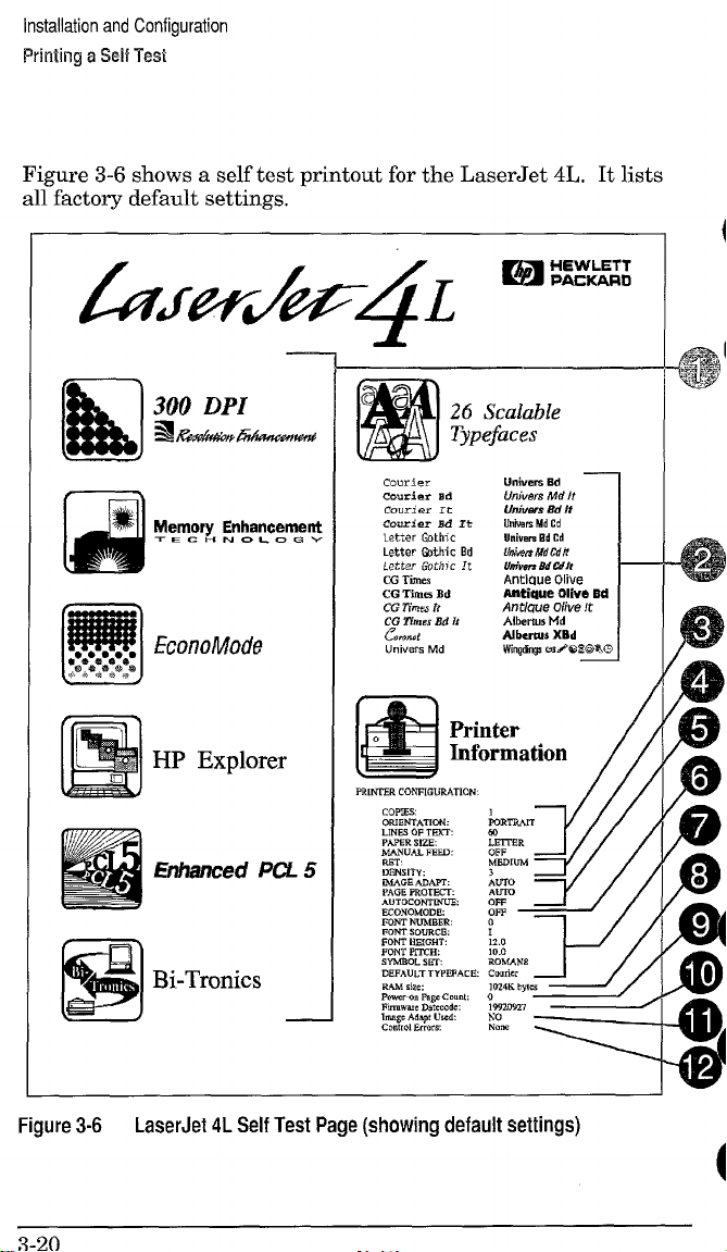
installation and Configuration
Printing a %4$ Tesi
Figure 3-6 shows a self test printout for the LaserJet 4L. It lists
al~factory default settings. “
J.
26
Scalable
Typefaces
Univm’s
Ed —
Un;vers Md It
8d M
Unfwers
Uuiws Md Cd
Umiwm EdCd
Umim MdCd,i
Utivets M Wh
Af)tlCme Ohre
Aatiaue Olive Bd
Antkwe Olive It
Albems Md
Albertus XBd
Wingdng3rsd%l%~%c
—
m
●****8****
b******@**
u
EconoMode
Courier
Courier ad
courier It
Courier Bd It
Letter Gothic
Letter W.hi c Bd
Letter Goth]c !t
CG Times
Bd
CG llmes
CG ?hes it
CG ZWnesEd h
C’J.A
Univers tvld
*
Ii!!51
Figure 3-6
HP Explorer
LmR.4m
W
L!3TBR
3“
OFF
Mmmn.i
Ehhanced PCL 5
Bi-Tronics
RAMs;,.
POW,* P.9gcCmmk o
F)rmvm, Datcmdc : 15520927 ~
IWO Adapt Uti
CO”tml Errors None
LTo
AUIO
OFF
OFF
0
1
12.0
10.0
EO!.(AN8
C.”rkr
,~~~
No
~ytc, ~
&
I-4 /
7
LaserJet 4L Self Test Page (showing default settings)
Page 84

Installation and Configuration
Printing a SM Test
The LaserJet 4L Self Test Fields
1. Printer Features List. This area can be used to check for
graphics print quality.
2. Scalable Typeface List. Samples of the printer’s internal
scalable typefaces.
hl’a’”a
KVv,w
Paper Handling. Shows the current paper settings.
3.
4.
Print Quality Adjustment. Current settings for print density
Removing ac power returns items 3 through 12
to facto~-default settings (shown in Figure 3-6).
and Resolution Enhancement (REt).
Memory Configuration. Settings for Image Adapt, Page
5.
Protection, and Auto Continue.
EconoMode. Setting of this toner-saving feature.
6.
Font Selection. Current default printer font settings.
7.
8.
RAM size. Shows the total amount of installed printer
memory, including added optional memory. Use to verify proper
memory installation.
Page Count. Shows approximately how many pages have been
9.
printed since the last power on. This value is returned to zero
whenever the printer is powered off.
10.Firmware Datecode. Shows the datecode of installed
firmware in YYYYMMDD format.
11.Image Adapt Status. Displays YES if the Image Adapt data
compression feature has been invoked since the last power on.
12.Control Errors. Shows the number of 1/0 or misprint errors
since the last power on.
3-21
Page 85

Installation and Configuration
Pining a sell Test
—..=——
$ERVICE MENU ~ ~20
PAGES
CR PAPER = lF1lER
SKIP DEMO = FALSE
!31AGNOSTICS = OFF
Ps E vu
m, P* ,,,s
PMALIE L MENU
HI,” S.EED
#lW FI:TNS
= m
= “ES
= ON
~
.—. . . . ..——
PRINTING MENU
COPIES = 3
PAPER - LETTER
::;:NTAT IO!. : :ol POrr$it 1
~ FEm . OFF
JOB MENU
,MEDROT ECT : yJo
RESWJTIDM
PERSONALV : $~:0
T,“SOUT
SERIAL WI!. U
SFXIAC . R.-232
P,C 1NC = El RIO*
mm RAW = 96C+
m POLARITY - nr
Pm ,.”fig m.,,
= ,fDlw
.—-m-......—
PCL MEMU
can mm : : <1..-.1)
FWT WBER
PITCH = 10.00
SW SE7 = RCMAM8
WNFIG MEMU
m WARN ~ :
AUID cCW
,,, s,,, = 3
TE$T MEW
,,,, ,,,,
Law SELF TEST
PC1 lVPE 11ST
,,, mm PA.f
m. .W, !, m,.,
,.—......
,$ TWf FACE L 1S1
,S DEMO PAGE
Page 86

Installation and Configuration
Printing a Self Test
The LaserJet 4MIJ4P/4MP Self Test Fields
The numbered items below refer to the Service Mode PCL
Configuration Self Test Page shown in Figure 3-7.
Menu Selections: Shows the current selections for all Service
1.
menu and user menus in the order that they appear in the
control panel display (refer to the Menu Maps, Figures 3-4 and
3-5). Use this information to verify the various menu selections.
PS Menu: Appears on the LaserJet 4P only if the Adobe
2.
PostScript SIMM is installed.
LocalTalk Information: LaserJet 4MP only. Lists the
3.
cotilgured network name and node identification number.
EconoMode Status: Shows current status, ON or OFF.
4.
Formatter Numbefi Shows the Formatter PCA’S serial
5.
number.
RAM Size: Shows how much memory is installed in the
6.
printer. 2048 Kbytes is standard. If optional memory has been
added, a self test can be used to verify installation.
Page Count: Shows how many pages have been printed over
‘7.
the life of the printer.
Firmware Datecode: Shows the datecode of the installed
8.
firmware (in YYYYMMDD format).
Installed Options/Personalities: Lists recognized cartridges
9.
and personalities. Use to verify installation.
10.REt Status: Shows the current Resolution Enhancement
setting, LIGHT, MEDIUM, DARK or OFF. (Default is
MEDIUM.)
11.Sample Printi Shows ripple print pattern (always in Courier).
This area is useful for checking print density and quality.
3-23
Page 87
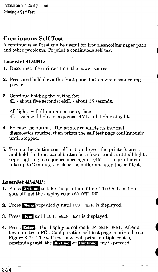
Installation and Configuration
Printing
a Self Test
Continuous Self Test
A continuous self test can be useful for troubleshooting paper path
and other problems. To print a continuous self test:
LaserJet 41J41VIIA
Disconnect the printer from the power source.
1.
Press and hold down the front panel button while connecting
2.
power.
3.
Continue holding the button for:
4L - about five seconds; 4ML - about 15 seconds.
All lights will illuminate at once, then:
4L - each will light in sequence; 4ML - all lights stay lit.
4.
Release the button. The printer conducts its internal
diagnostics routine, then prints the self test page continuously
until stopped.
To stop the continuous self test (and reset the printer), press
5.
and hold the front panel button for a few seconds until all lights
begin lighting in sequence once again. (4ML - the printer can
take up to 2 minutes to clear the buffer and stop the self test.)
LaserJet 4P/4MP
Press - to take the printer offline. The On Line light
1.
goes off and the display reads W3
Press - repeatedly until T!Z5T PEW-l is displayed.
2.
Press ~ until
3.
Press ~. The display panel reads W
4.
EUHT SELF TE:ST is displayed.
IHFFL1 NE.
SELF TEST. After a
few minutes a PGL Confirmation self test ~a~e is minted (see
Figure 3-7). The self test-page will print m~l~ple ~opies,
continuing until the - or ~ key is pressed.
3-24
Page 88
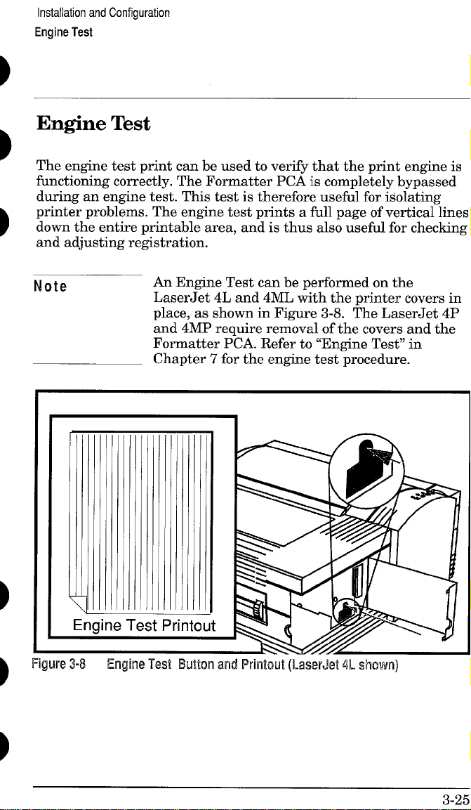
Installation and Configuration
Engine Test
Engine Test
The engine test print can be used to verify that the print engine is
functioning correctly. The Formatter PCA is completely bypassed
during an engine test. This testis therefore useful for isolating
printer problems. The engine test prints a fhll page of vertical lines
down the entire printable area, and is thus also useful for checking
and adjusting re&istration.
Note
Figure 3-8
An Engine Test can be performed on the
LaserJet 4L and 4ML with the printer covers in
place, as shown in Figure 3-8. The LaserJet 4P
and 4MP require removal of the covers and the
Formatter PCA. Refer to “Engine Test” in
Chapter 7 for the engine test procedure.
—
Engine Test EWcm and Printout (LaserJet 4L shown]
3-25
Page 89

Installation and Configuration
Resetting the Printer
Resetting the Printer
Resetting the printer clears the printer’s memory, including
unprinted data, downloaded fonts, and macros. It also removes
some error conditions, and resets to factory default settings. The
printer can be reset at any time, except when there is a service
error condition.
LaserJet 4L/4ML:
1. Hold the front panel button down for at least five seconds.
Release when all lights illuminate in succession from bottom to
top.
2. After the printer has finished the reset, the Ready light comes
on (if there are no printer errors).
LaserJet 4P/4MP:
The LaserJet 4P/4MP has several kinds of resets, as explained
below.
Simple Reset
A simple reset does the following:
Clears the printer’s page buffer.
Removes all temporary typefaces and macros.
Makes the current user-selected defaults “active” (making them
the default values until you change them again).
Purges the input buffer of the active 1/0 (the other I/O buffer is
not affected).
To perform a simple reset:
1. Press_ to take the printer offline. The On Line light
goes off and 2S ]H%i-Ii!~ appears on the display.
2. While holding down the ~ key, press - briefly.
3. S7 ~~s~~ appears on the
the on-line, 5E Z=W+ state.
3-26
display. Then the printer returns to
Page 90

Installation and Configuration
Resetting the Printer
The Menu of Resets
Additional reset options are available through the Menu of Resets.
Use the Menu of Resets option with caution. It can result in loss of
buffered page data or printer configuration data. You should only
use it when:
You wish to restore the default printer settings.
Communication between the printer and computer is
interrupted.
You are using both the serial and the ~arallel I/O ~orts. and one
.
of the ports ii having problems. ‘
To access the Menu of Resets:
1.
Press - to take the printer offline.
2.
Hold down both the ~ and ~ keys for at least 10
seconds until ==:;:=-~=mw!appears on the display.
3.
4.
❑ or H to cycle through the items.
Use
Press ~ to select your choice of resets. An asterisk *
.
appears by the reset option.
Press - to execute the reset.
5.
The foIlowing table shows the three reset options.
Table 3-2
Menu Selection
RESET.MENU
Menu of Resets (LaserJet 4P/4MP)
Printer Response
09 MENU RESET
RESET=MENU restores most of the printer’s
Explanation
factory default settings. It also performs a simple
reset. Items in the Config, Parallel, and Serial
Menus are not reset, RESET=MENU clears
only the active input buffer.
RESET.ACTIVE 1/0 09 RESET ACTIVE 1/0
RESET= ACTIVE 1/0 clears the input and output
buffers for the active //0 dy, and performs a
simple reset.
RESET ALL l/O 09 RESET ALL 1/0
RESET=ALL l/O clears the input and output
buffers for both 1/0s, and performs a simple
reset.
Page 91

Installation and Configuration
Resetting the Printer
The Cold Reset (LaserJet 4ML/4P/4MP)
Cold reset clears all data from the printer’s memory and sets all
the defaults back to the factory settings. (NOTE: The LaserJet 4L
is effectively “cold reset” whenever power is removed.)
To perform a cold reset:
LaserJet 4ML:
Cold Reset can be performed on the LaserJet 4ML through the HP
Explorer Utility (refer to the Software/Solutions package for
instructions).
LaserJet 4P/4MP:
1.
Turn off the printer.
2.
While holding the _ key down, turn the printer on.
m !CDLE,
13z !<ELF
RESET appears briefly on the display, then
TEN appears.
a
After about 30 seconds, fi~i
3.
CIFFL1 w appears on the display, and
the cold reset is complete.
4.
Press - to return the printer on line. MURE=o’,’appears
on the display.
Page 92

Installation and Configuration
PJL Software Commands
PJL Software Commands
Many of the control panel functions explained in this chapter can
also be accessed through PJL software commands sent from the
host computer. For the LaserJet 4ML printer, functions such as
entering Service Mode, are accessible
commands. (Note that Service Mode is available only on the
LaserJet 4ML, 4P and 4MP, and
The following example shows how to use PJL commands to enter
Service Mode and perform various Service Mode configuration
tasks.
only through PJL
not on the LaserJet 4L.)
Note
Table 3-3
PJL Command
‘cYo-l 2345X@PJL
@PJL SET SERVICEMODE=HPBOISEIE
@PJL SET PAGES=O
@PJL SET CRPAPER=LETTER
@PJL SET SKIPDEMO=FALSE
@PJL SET DIAGNOSTICS=OFF
@PJL SET SERVICEMODE=EXIT
@PJL DEFAULT PAPER. LETTER
@PJL RESET
‘cYo-l 2345X
Ecz
ECE
Text is CASE-sensitive in PJL; enter exactly as
shown. The Ec symbol stands for the ASCII
escape character (ESC or /027). When the PJL
code is entered, print the data file (or use the
COPY command to copy it to the printer).
DOS
Example: PJL Service Mode Commands
Explanation
Start PJL job.
Enter Service Mode
Set page count [= XXXXX]
Sets cold reset page size [= Letter/A4]
Skips demo/PCL type page [= true/false]
Sets diagnostics [= OFF/ON] (for ISV use)
Exits Service Mode
Selects user paper size default
Performs PJL reset
Exits PJL mode
Prints Self-Test page
Resets the printer.
3-29
Page 93

Installation and Configuration
PJL Software Commands
3-30
Page 94
4
b’
Maintenance
Page 95

Maintenance
Service Checkpoints
Service Checkpoints
Figure 4-1 Service Checkpoints
1. Upper Fusing Assembly,
2. Beam-to-Drum Mirror.
3. Transfer Roller Assembly.
4. Toner Cartridge.
5, Registration Roller.
6. Front Oblique Roller.
7. Pickup Feed D-Roller.
8, Photosensitive Drum.
9. Fusing Pressure Roller.
10. Face-Up/Face-Down Deflector.
Page 96

Maintenance
Life Expectancy of Consumables
Life Expectancy of Consumables
Always inspect the components listed in Table 4-1 for wear when
servicing the printer. Replace these components as needed, based
on printer failures or wear, not strictly on usage.
Table4-1 l-ik l%pectamy cdConsumables
EST
DESCRIPTION PART NO.
LIFE
(P9S)
Toner Cartridge
(user replaceable)
92274A
When print becomes faint,
3000’
shake cartridge to distribute
remaining toner.
Transfer Roller RF5-0596-OOOCN 100,000 May affect print quality
and /or ~a~er movement,
Pickup Feed D-Roller
RBI-3368-OOCN
100,000
Look for glazing andlor
cracks.
Pickup Assembly RG5-0796-OOOCN
100,000
Look for glazing andlor
cracks, gear wear, sticky
solenoids, etc.
Front Oblique Roller
RG5-0669-OOOCN
Assembly
Fusing Assembly
100-120 V, 50/60 Hz
RG5-0676-OOOCN
(exchange part no.) C2003-69001
100,000
100,000
Look for glazing andior
cracks,
May affect print quality and
/or paper movement, Look
for marks on lower pressure
roller or upper Teflon sleeve.
220-240 V, 50 Hz RG5-0677-OOOCN
(exchange parl no.)
* The estimated toner cartridge life is based on Letter or A4 size paper with an
average of 5% toner coverage and a medium density setting. Toner cartridge life can
be extended further by conserving toner using the printer’s EconoMode feature.
C2003-69002
1
REMARKS
4-3
Page 97

Maintenance
Life Expectancy of Consumables
Toner Cartridge Life
The toner cartridge has been designed to simplify the replacement
of the printer’s major “consumable” parts. The toner cartridge
contains the printing mechanism and a supply of toner.
A toner cartridge will print approximately 3000 pages when using
a typical word processing application, in which text covers about
5% of the page (see Figure 4-2).
Figure
4-4
4..2
Sample 5% Rage Coverage
Page 98

Maintenance
Life Expectancy of Consumables
When regularly printing pages with less coverage, such as short
memos, a toner cartridge should print over 3000 pages. However,
if routinely printing very dense print, the cartridge will not print a
full 3000 pages.
Note
For best results, always use a toner cartridge
before the expiration date stamped on the toner
cartridge box.
Saving Toner with EconoMode
Toner cartridge life can be extended dramatically by using the
EconoMode printing feature of the printer. EconoMode can be
turned on or off via the printer’s front panel (LaserJet 4P/4MP
only), through HP Explorer’s Remote Control Panel or through a
software application with the appropriate printer driver. See
Chapter 3 for information on the HP Explorer Remote Control
Panel.
Notes
EconoMode functions in portrait orientation only.
Some software applications may refer to this as
“draft mode.”
Software settings always override front control
panel selections (LaserJet 4P/4MP).
4-5
Page 99

Maintenance
Cleaning Printer
(hnponents
Cleaning Printer Components
CAUTION
Table4-2
COMPONENT
Outside Covers
Inside General
Front Oblique Roller
Pickup Feed D-Roller
Registration Roller
Transfer Roller
Beam-to-Drum Mirror
Fusing Pressure Roller Use a cloth or swab dampened with water.
Face-up Deflector
4nti-Static Teeth
Do not use ammonia-based cleaners in or around
the printer. They will cause damage to the toner
cartridge’s photosensitive drum.
—
Cleaning Printer Components
I
Use a water-dampened cloth. Do not use solvents or
ammonia-based cleaners.
Use a dry, lint free cloth. Remove all dust, spilled toner,
and paper particles.
Use a cloth or swab dampened with ethyl or isopropyl
alcohol.
Use a water-dampened lint-free cloth.
Use a dry lint-free cloth,
Use a dry, lint-free cloth. DO NOT TOUCH with your
fingers.
Use filtered, compressed air first. If not effective, use a lint-
free cloth or swab dampened with lens cleaner.
Use a cloth or swab dampened with water.
Use compressed air. Refer to Chapter 6 for removal
procedure. WARNING!:The Anti-Static Teeth are
extremely sharp. Be careful!
CLEANING METHOD/NOTES
I
4-6
Page 100

Maintenance
Cleaning Printer Components
Cleaning Spilled Toner
Defective toner cartridges can develop leaks. In addition, after a
paper jam has occurred, there may be some toner remaining on the
rollers and guides inside the printer. The pages that print
immediately after the jam may pick up this toner.
Clean spilled toner with a cloth dampened in cold water. Do not
touch the Transfer Roller with the damp cloth or your fingers. Do
not use a vacuum cleaner unless it is equipped with a micro-fine
particle filter.
Note
If toner gets on your clothing, use cold water to
remove it. Hot water sets toner stains into fabric.
4-7
 Loading...