

HP 3PAR StoreServ 8000 Service And Upgrade Manual

HPE 3PAR StoreServ 8000 Storage Service and Upgrade Guide: Customer Edition
Abstract
This document provides information and instructions to guide you in servicing and upgrading
the HPE 3PAR StoreServ 8000 Storage system without the assistance of an authorized
service provider. If assistance is needed, contact your HPE Sales Representative or HPE
Partner.
Part Number: QL226-10543
Published: December 2018
Edition: 2

©
Copyright 2015-2018 Hewlett Packard Enterprise Development LP
Notices
The information contained herein is subject to change without notice. The only warranties for Hewlett
Packard Enterprise products and services are set forth in the express warranty statements accompanying
such products and services. Nothing herein should be construed as constituting an additional warranty.
Hewlett Packard Enterprise shall not be liable for technical or editorial errors or omissions contained
herein.
Confidential computer software. Valid license from Hewlett Packard Enterprise required for possession,
use, or copying. Consistent with FAR 12.211 and 12.212, Commercial Computer Software, Computer
Software Documentation, and Technical Data for Commercial Items are licensed to the U.S. Government
under vendor's standard commercial license.
Links to third-party websites take you outside the Hewlett Packard Enterprise website. Hewlett Packard
Enterprise has no control over and is not responsible for information outside the Hewlett Packard
Enterprise website.
Acknowledgments
Microsoft® and Windows® are either registered trademarks or trademarks of Microsoft Corporation in the
United States and/or other countries.
UNIX® is a registered trademark of The Open Group.
Revision history
Part Number Publication
QL226-10543 December 2018 3
QL226-99885 June 2018 2
QL226-99284 March 2017 1
Edition Summary of changes
date
• Added a link to the HPE Parts Store in "Spare
part number"; removed parts catalog
• Updated "Guidelines for cabling"
• Support for a new physical service processor,
HPE ProLiant DL360 Gen10 Server
• Support for direct-current (DC) physical service
processor, DC breaker panel, DC power cooling
module, and DC switch only qualified and
supported with HPE 3PAR OS 3.3.1 or later
• The HPE StoreFront Remote (SFRM) content
has been replaced with HPE InfoSight content.
• Correction for replacing a drive; Maintenance
Mode not set during replacement of a failed
drive
• Support for HPE 3PAR OS 3.2.2 and 3.3.1 or
later
• Support for HPE 3PAR Service Processor
SP4.x and 5.x or later

Contents
Preparation.............................................................................................. 7
Service..................................................................................................... 8
Videos for service and upgrade.................................................................................................... 7
Customer self repair......................................................................................................................8
Breaker panel replacement...........................................................................................................8
Controller node replacement—Two-node system only................................................................. 9
Replacing a controller node—Two-node system only—SP 4.x..........................................9
Replacing a controller node—Two-node system only—SP 5.x........................................12
Drive replacement.......................................................................................................................16
Replacing a drive—SP 4.x............................................................................................... 16
Replacing a drive—SP 5.x............................................................................................... 21
Power cooling module or battery replacement............................................................................25
Replace the alternating-current power cooling module battery in a controller node
enclosure—SP 5.x............................................................................................................25
Replacing an alternating-current power cooling module in a controller node
enclosure—SP 5.x............................................................................................................29
Replacing an alternating-current power cooling module in a drive enclosure—SP 5.x....33
Replacing a direct-current power cooling module battery in a controller node
enclosure—SP 5.x............................................................................................................36
Replacing the direct-current power cooling module in a controller node enclosure—
SP 5.x...............................................................................................................................41
Replacing a direct-current power cooling module in a drive enclosure—SP 5.x..............46
SFP transceiver replacement......................................................................................................50
Replacing an SFP transceiver—SP 4.x........................................................................... 50
Replacing an SFP transceiver—SP 5.x........................................................................... 53
Switch replacement.....................................................................................................................55
Upgrade..................................................................................................57
Customer self upgrade................................................................................................................57
Drive additions............................................................................................................................ 57
Guidelines for the drive installation ................................................................................. 57
Guidelines for a drive addition .........................................................................................61
Adding drives—SP 4.x..................................................................................................... 61
Adding drives—SP 5.x..................................................................................................... 64
More information...................................................................................68
About the software on a virtual service processor or physical service processor.......................68
Connection methods for the HPE 3PAR Service Processor............................................ 68
Connecting to HPE 3PAR Service Processor 5.x from a web browser................. 69
Connecting to the HPE 3PAR Service Processor 4.x from a web browser........... 69
Connecting to the Linux console of the HPE 3PAR Service Processor
through a Secure Shell session.............................................................................69
Connecting to the Linux console of the HPE 3PAR Service Processor
through a VMware vSphere Client........................................................................ 69
3

Connecting a service laptop to the physical HPE 3PAR Service Processor
through the service port.........................................................................................69
Interfaces for the HPE 3PAR Service Processor software............................................... 70
Accessing the SP 5.x Service Console interface.................................................. 71
Accessing the SP 5.x Text-Based User Interface.................................................. 71
Accessing the Service Processor Onsite Customer Care interface—SP 4.x........ 71
Accessing the SP 4.x SPMaint interface directly...................................................71
Accessing the CLI session from the Service Console interface, HPE 3PAR
Service Processor 5.x............................................................................................71
Accessing the interactive CLI interface from the Text-Based User Interface,
HPE 3PAR Service Processor 5.x......................................................................... 72
Accessing the CLI session from the Service Processor Onsite Customer
Care interface, HPE 3PAR Service Processor 4.x ............................................... 72
Accessing the interactive CLI interface from the SPMaint interface, HPE
3PAR Service Processor 4.x................................................................................. 73
Network and firewall support access................................................................................73
Firewall and proxy server configuration.................................................................73
About the HPE 3PAR StoreServ Management Console.............................................................74
HPE 3PAR StoreServ Management Console connection................................................ 75
HPE 3PAR StoreServ Management Console interfaces.................................................. 75
About the HPE InfoSight platform............................................................................................... 75
Accessing the HPE InfoSight platform and registering the storage system: Process
overview........................................................................................................................... 76
Creating an account to access the HPE InfoSight web portal..........................................76
Registering the storage system with the HPE InfoSight web portal using the HPE
3PAR StoreServ Management Console...........................................................................76
Removing a storage system from the HPE InfoSight platform.........................................78
Accounts and credentials for service.......................................................................................... 78
Time-based password (strong password)........................................................................ 78
Encryption-based password (strong password)............................................................... 78
HPE 3PAR Service Processor accounts for service.........................................................79
Setting time-based or encryption-based password option from the Service
Console interface of the HPE 3PAR Service Processor 5.x.................................. 81
Generating the encryption-based ciphertext from the Service Console
interface of the HPE 3PAR Service Processor 5.x................................................ 82
Setting time-based or encryption-based password option from the Text-
Based User Interface of the HPE 3PAR Service Processor 5.x............................ 82
Generating the encryption-based ciphertext from the Text-Based User
Interface of the HPE 3PAR Service Processor 5.x................................................ 83
HPE 3PAR StoreServ Storage system accounts for service............................................83
Setting time-based or encryption-based password option for a storage
system account......................................................................................................84
Generating the encryption-based ciphertext for a storage system account.......... 85
Regenerating the encryption-based ciphertext for a storage system account...... 85
Alert notifications for the storage system—SP 5.x......................................................................85
Browser warning when connecting to the service processor...................................................... 86
Component information...............................................................................................................89
Adapters information (optional component)..................................................................... 89
Four-Port 16 Gb FC Host PCIe Adapter information.............................................89
Two-Port 10 Gb iSCSI/FCoE CNA Host PCIe Adapter information...................... 90
Two-Port 10 GbE NIC Host PCIe Adapter information..........................................91
Four-Port 1 GbE NIC Host PCIe Adapter information........................................... 91
Four-port 16 Gb FC/10 Gb Ethernet Combo Adapter information.........................92
Four-port 10 Gb iSCSI/10 Gb Ethernet Combo Adapter information.................... 92
Two-port 32Gb FC HBA information......................................................................93
Breaker panel information................................................................................................ 93
Direct-current E-T-A Breaker Panel and Grounding Bar information.................... 93
4

Controller node information..............................................................................................93
Drive information.............................................................................................................. 97
Enclosures information.....................................................................................................97
Controller node enclosure and drive enclosures information front view................97
Controller node enclosure information rear view...................................................99
Drive enclosure information rear view................................................................. 100
I/O module information...................................................................................................102
Power cooling module information................................................................................. 103
Power cooling module information, alternating-current, controller node
enclosure.............................................................................................................103
Power cooling module information, alternating-current, drive enclosure.............104
Power cooling module information, direct-current system...................................105
Power distribution unit information................................................................................. 106
Service processor information........................................................................................106
Physical service processor information, HPE ProLiant DL120 Gen9 Server...... 106
Physical service processor information, HPE ProLiant DL360 Gen10 Server.... 108
Switch information..........................................................................................................109
Direct-current switch information.........................................................................109
Component LEDs......................................................................................................................109
Adapter LEDs.................................................................................................................109
Four-Port 16 Gb FC Host PCIe Adapter LEDs....................................................109
Two-Port 10 Gb iSCSI/FCoE CNA Host PCIe Adapter LEDs..............................110
Two-Port 10 GbE NIC Host PCIe Adapter LEDs................................................. 110
Four-Port 1 GbE NIC Host PCIe Adapter LEDs...................................................111
Four-Port 16 Gb FC/10 GbE NIC Host PCIe Combo Adapter LEDs................... 112
Four-port 10 Gb iSCSI/10 Gb Ethernet Combo Adapter LEDs............................112
Two-Port 32 Gb FC HBA LEDs............................................................................113
Controller node LEDs..................................................................................................... 114
Drive LEDs..................................................................................................................... 118
I/O module LEDs............................................................................................................120
Power cooling module LEDs.......................................................................................... 122
Power cooling module LEDs, alternating-current, controller node enclosure......122
Power cooling module LEDs, alternating-current, drive enclosure......................123
Power cooling module LEDs, direct-current system............................................124
Service processor LEDs.................................................................................................125
Physical service processor LEDs, HPE ProLiant DL120 Gen9 Server............... 126
Physical service processor LEDs, HPE ProLiant DL360 Gen10 Server............. 128
System status LEDs.......................................................................................................130
Controller node rescue..............................................................................................................131
Initiating an automatic node-to-node rescue.................................................................. 132
Customer self repair..................................................................................................................134
Guidelines for cabling............................................................................................................... 134
Removing the cable restraint shipping brackets....................................................................... 136
Spare part number.................................................................................................................... 136
Troubleshooting.................................................................................. 138
Alerts issued by the storage system and processed by the service processor.........................138
Components functions.............................................................................................................. 138
alert ............................................................................................................................139
ao ..................................................................................................................................139
cabling ....................................................................................................................... 140
cage ..............................................................................................................................141
cert ..............................................................................................................................145
dar ................................................................................................................................145
date ..............................................................................................................................146
5

file ..............................................................................................................................146
fs ..................................................................................................................................148
host ..............................................................................................................................149
ld ..................................................................................................................................150
license ....................................................................................................................... 152
network ....................................................................................................................... 152
pd ..................................................................................................................................153
pdch ..............................................................................................................................157
port ..............................................................................................................................158
qos ................................................................................................................................160
rc ..................................................................................................................................161
snmp ..............................................................................................................................162
sp ..................................................................................................................................162
task ..............................................................................................................................162
vlun ..............................................................................................................................163
vv ..................................................................................................................................164
Controlled thermal shutdown.................................................................................................... 165
Log files collection.....................................................................................................................165
Collecting HPE 3PAR SmartStart log files—OS 3.2.2 and SP 4.x................................. 165
Collecting service processor log files—SP 5.x...............................................................165
Collecting the service processor log files—SP4.x..........................................................166
Websites.............................................................................................. 167
Support and other resources.............................................................168
Accessing Hewlett Packard Enterprise Support....................................................................... 168
Accessing updates....................................................................................................................168
Customer self repair..................................................................................................................169
Remote support........................................................................................................................ 169
Warranty information.................................................................................................................169
Regulatory information..............................................................................................................170
Documentation feedback.......................................................................................................... 170
Acronyms.............................................................................................171
6

Preparation
Videos for service and upgrade
Customer self repair video
With HPE 3PAR OS 3.3.1, the customer self repair (CSR) video is available at the hpe.com website:
www.hpe.com/support/3PAR8000CSRVideo
With HPE 3PAR OS 3.2.2, the customer self repair (CSR) videos are available at the CSR Services
Media Library website:
www.hpe.com/support/sml-csr
1. From the Product category list, select Storage.
2. From the Product family list, select 3PAR StoreServ Storage.
3. From the Product series list, select the product.
Links to the available videos are displayed.
Customer self upgrade video
With HPE 3PAR OS 3.3.1, the customer self upgrade (CSU) video is available at the hpe.com website:
www.hpe.com/support/3PAR8000CSUVideo
Preparation 7
Service
Customer self repair
Customer self repair (CSR) is a key component of Hewlett Packard Enterprise warranty terms. Once the
failure of a hardware component has been confirmed, CSR enables Hewlett Packard Enterpriseto ship
replacement parts directly to you. Parts are usually shipped overnight. CSR warranty terms and
conditions are included in the warranty statement for the product, which can be found in the box with the
product.
For more details about CSR, contact an authorized service provider or see the Hewlett Packard
Enterprise Customer Self Repair website:
www.hpe.com/info/selfrepair
IMPORTANT: Some components are not designed for CSR. To satisfy the customer warranty for
service of non-CSR components, an authorized service provider has to service the non-CSR
components.
CSR types
• Mandatory CSR parts (warranty only)—On-site or return-to-depot support for replacement of this
part is not provided under the warranty. You can install a mandatory CSR part yourself or pay Hewlett
Packard Enterprise service personnel to do the installation. A mandatory CSR part typically does not
need tools to replace, consists of a single part, has minimum cabling, and is plug-and-play.
• Optional CSR parts—You can replace this optional CSR part yourself or have it replaced by Hewlett
Packard Enterprise service personnel at no additional charge during the warranty period. Replacement
may require tools, the removal of other parts, more involved cabling, and configuration and setup
following replacement.
Breaker panel replacement
The E-T-A Breaker Panel is a direct-current component supported for the HPE 3PAR StoreServ 8000
Storage system.
WARNING: Since there is a risk of injury from electric shock or high energy levels, only a certified
electrician who knows about the procedures, precautions, and hazards associated with directcurrent (DC) power should perform the power wiring, cabling, routine maintenance, and service of a
storage system installed in a direct-current power environment. Hewlett Packard Enterprise and
partner service personnel are not authorized to perform DC power wiring or cabling.
IMPORTANT: The storage system ordered for installation in a direct-current (DC) power
environment requires the installation of DC-specific components. Use of components with
alternating-current (AC) power in the DC storage system is prohibited.
IMPORTANT: The direct-current components are qualified and supported only with a direct-current
HPE 3PAR StoreServ 8000 Storage system running HPE 3PAR OS 3.3.1 and later versions.
When support is needed for the direct-currentE-T-A Breaker Panel, see www.e-t-a.com/ for support
contact information.
8 Service
Controller node replacement—Two-node system only
IMPORTANT: Only a controller node for a two-node system that does not contain a host PCIe
adapter qualifies for customer self repair (CSR). It is the entire controller node that qualifies for CSR
and excludes the repair of internal components within the controller node. Any internal components
within the controller node are only serviceable by an authorized service provider (ASP).
Replacing a controller node—Two-node system only—SP 4.x
This procedure is for the replacement of an HPE 3PAR StoreServ 8000 Storage controller node using
HPE 3PAR Service Processor (SP) 4.x.
IMPORTANT:
• To avoid possible data loss, shut down (halt) and remove only one controller node at a time from
the storage system.
• To prevent overheating, do not leave the controller node bay empty for more than 30 minutes.
• Verify that host multipathing is functional.
Prerequisites
Order a replacement component by contacting your Hewlett Packard Enterprise authorized service
provider.
Shut down (halt) the failed controller node by contacting your Hewlett Packard Enterprise authorized
service provider for assistance.
Procedure
Preparation
1. Unpack the component and place on an ESD safe mat.
2. Connect to the HPE 3PAR Service Processor.
Browse to either the IP address or hostname: https://<sp_ip_address> or https://
<hostname> .
3. Log in to the HPE 3PAR Service Processor (SP).
With the 3parcust account credentials, the Service Processor Onsite Customer Care (SPOCC)
interface displays.
4. Initiate a maintenance window to stop the system from sending alerts to Hewlett Packard Enterprise.
a. From the SPOCC interface main menu, select SPMAINT in the left navigation pane.
b. From the SPMaint interface main menu under Service Processor - SP Maintenance, select
StoreServ Configuration Management.
c. Under Service Processor - StoreServ Configuration, select Modify under Action.
d. Under Service Processor - StoreServ Info, select On for the Maintenance Mode setting.
5. Initiate Check Health on the storage system.
Service 9

a. From the SPOCC interface main menu, click Support in the left navigation pane.
b. From the Service Processor - Support page, under StoreServs, click Health Check in the
Action column.
A pop-up window displays a status message while the health check runs.
When running the Health Check using Internet Explorer, the screen might remain blank while
information is gathered. This process could take a few minutes before displaying results. Wait for
the process to complete and do not attempt to cancel or close the browser.
c. To review the report, click either Details or View Summary.
CAUTION: If health issues are identified during the Check Health scan, resolve these issues
before continuing. Refer to the details in the Check Health results and contact Hewlett Packard
Enterprise Support if necessary.
6. Locate the failed and shut down controller node by referring to the LEDs.
Some faults illuminate the blue UID/Service LED, which helps you locate the failed component.
When the UID/Service LED is solid blue and the Status LED is rapidly flashing green, a controller
node is shut down. Depending on the nature of the controller node failure, the Fault LED might be
solid amber.
The Fault LED for the other active controller node in the cluster will be flashing, indicating that one of
the other controller nodes in the cluster is shut down.
7. Verify that all cables are labeled with their location.
Removal
8. Remove the cables from the controller node.
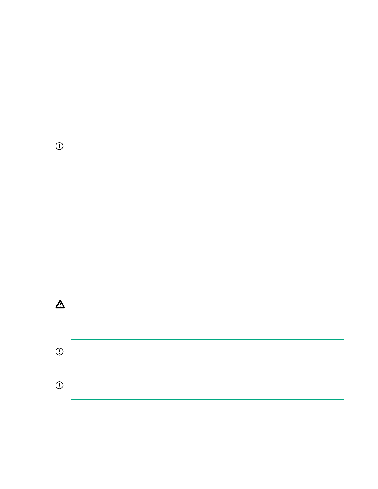
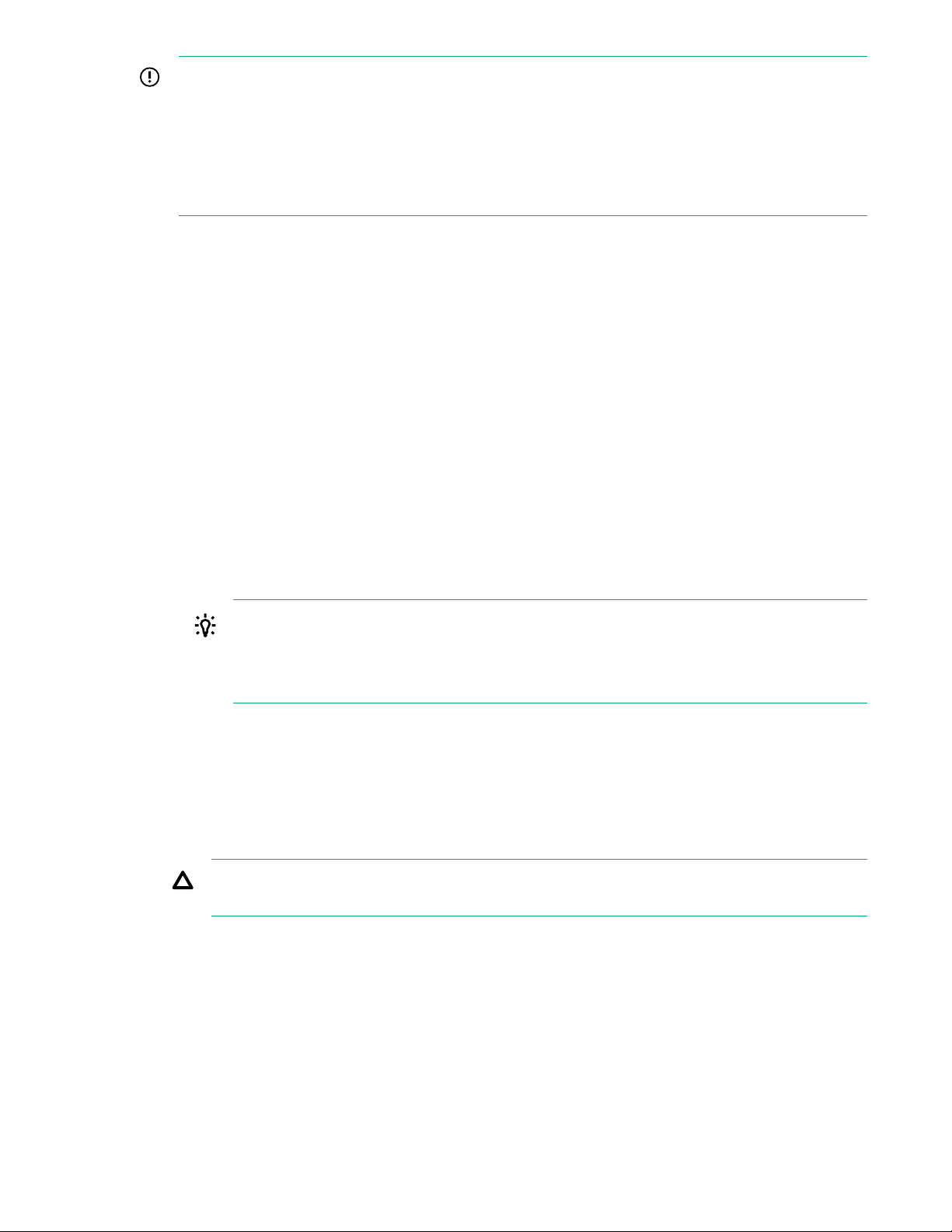
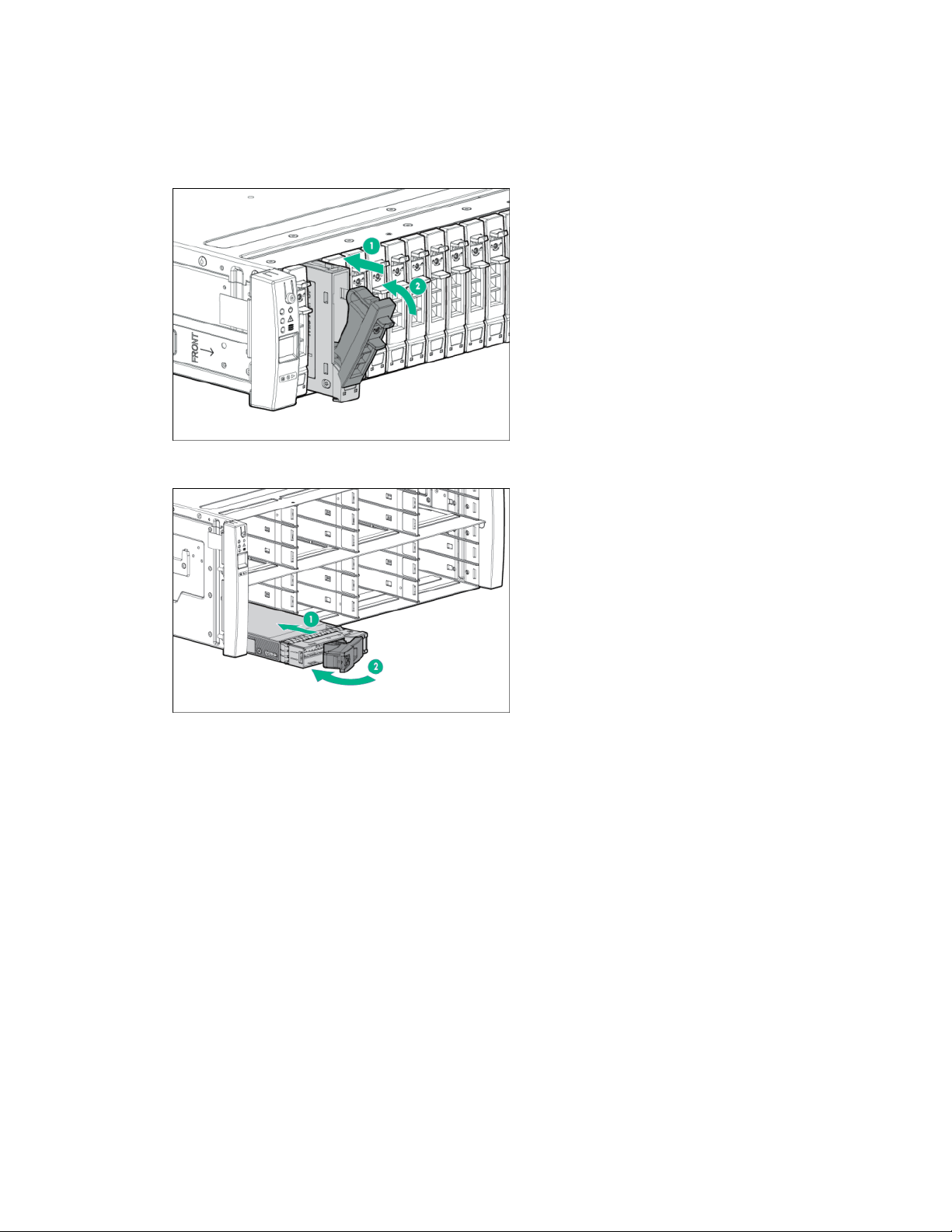
9. Remove the controller node. See Figure 1: Removing the controller node on page 10.
a. Pull to extend the gray rod of the controller node to the extracted position (1).
b. When the controller node is halfway out of the enclosure, support it from underneath and slide it
out completely (2).
c. Place the controller node on the ESD safe mat.
10. Push in the gray rod to ready it for packaging and to provide differentiation from the replacement
Replacement
11. Partially install the controller node.
10 Service
Figure 1: Removing the controller node
controller node.
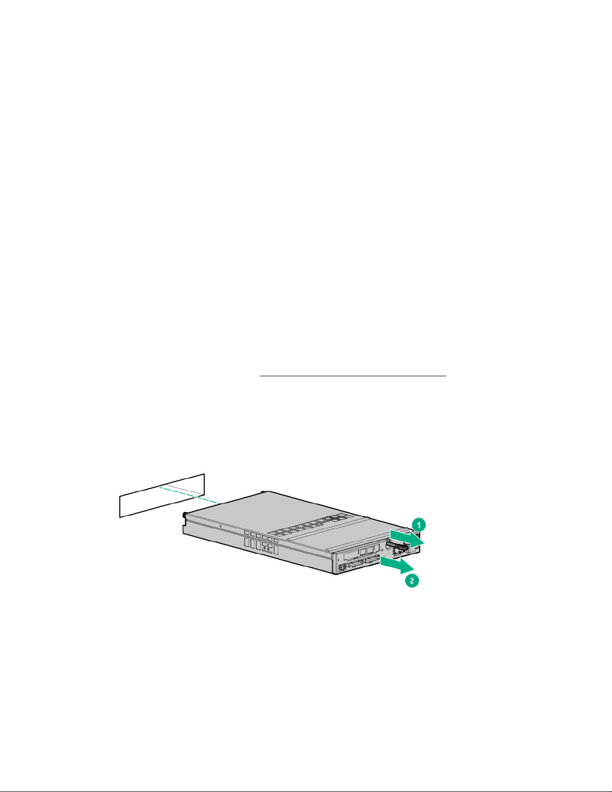
a. Pull to extend the gray rod of the controller node to the extracted position.
Figure 2: Extending the controller node rod
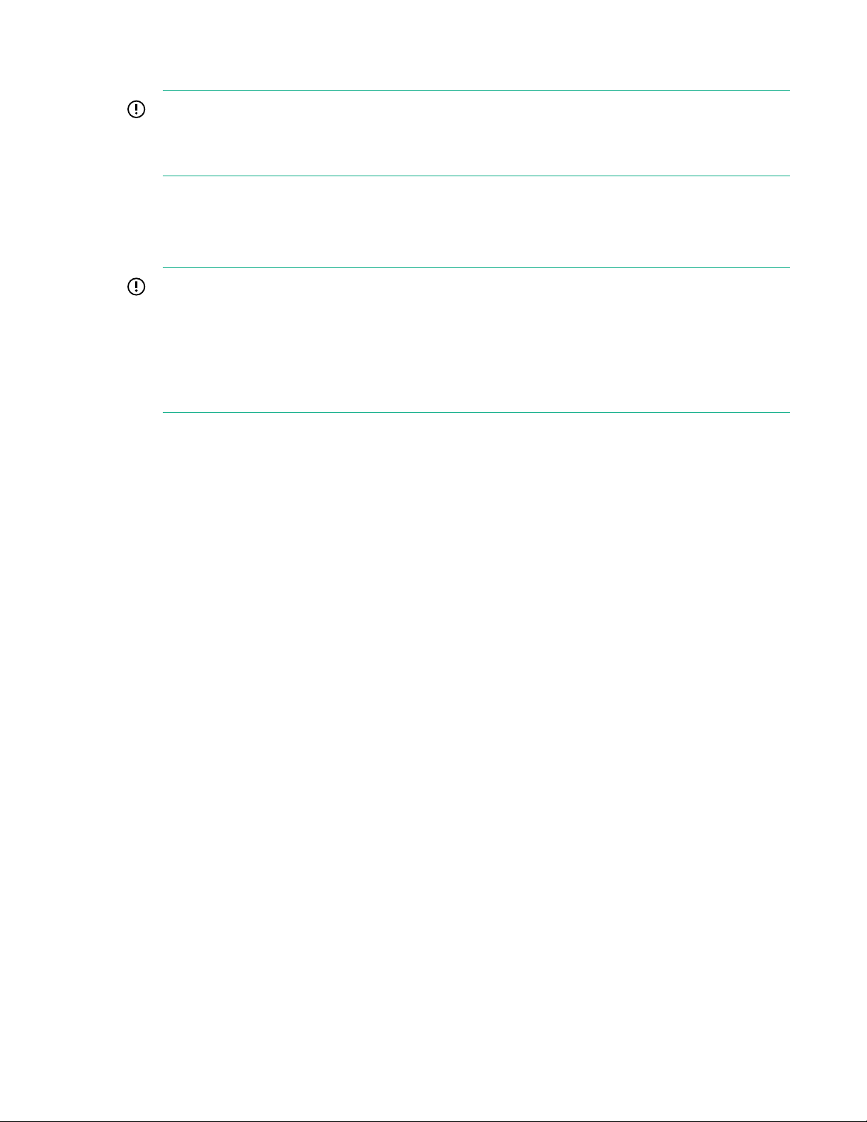
b. Confirm that the controller node is correctly oriented. In the controller node enclosure, the pair is
installed with each controller node oriented 180° from each other.
Figure 3: Orientation of a controller node pair
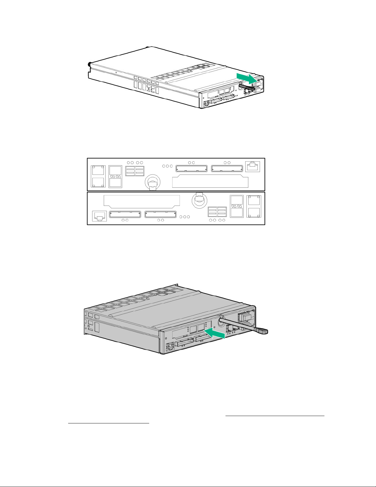
c. Partially install the controller node into the slot. Using two hands to grasp each side of the
replacement controller node, align it with the grooves in the slot, and slide it into the slot until it
halts against the insertion mechanism that is inside of the slot. Do not fully insert the controller
node in the slot at this time, because the cables must be reconnected before it is fully seated.
Figure 4: Partially install the controller node into the slot
12. Reconnect the cables to the controller node.
While the controller node is still only partially inserted in the slot, reconnect the cables to the
controller node.
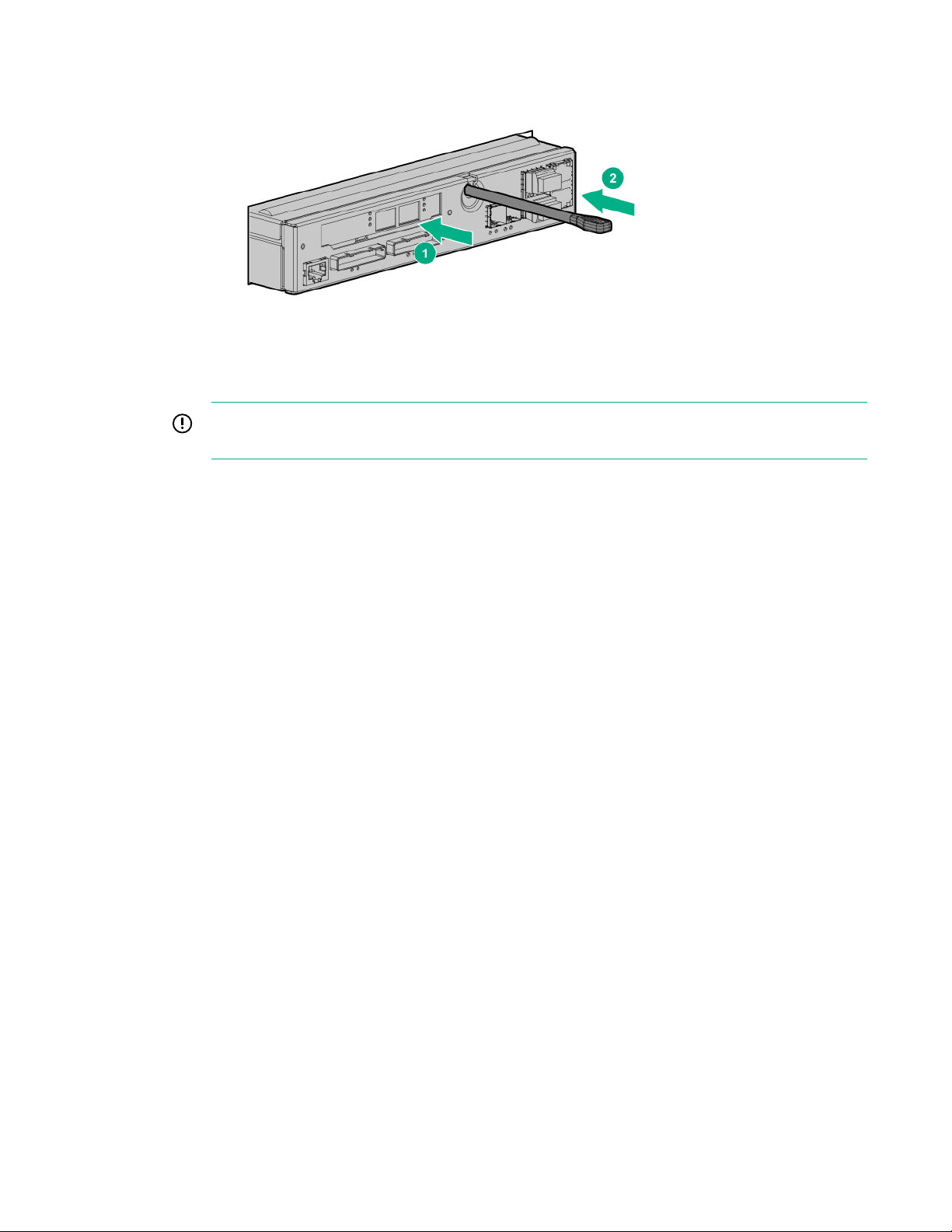
13. Fully install and seat the controller node into the slot. See Figure 5: Fully install and seat the
controller node into the slot on page 12.
Service 11
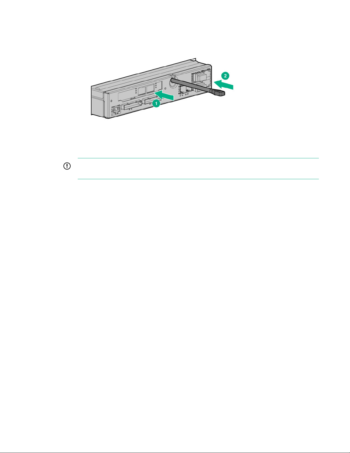
Slide in the controller node (1) while pushing in on the gray rod until it stops (2).
If the UID LED is flashing blue after two minutes, this LED status indicates that the replacement
controller node is not properly seated, so repeat this step.
Figure 5: Fully install and seat the controller node into the slot
Once inserted, the replacement controller node powers up and goes through the automatic node-tonode rescue before joining the cluster. This process might take up to 10 minutes.
IMPORTANT: If the automatic node-to-node rescue does not start automatically, contact your
authorized service provider.
Verification
14. Verify that the controller node has joined the cluster.
Confirm that the green Status LED on the controller node is flashing in synchronization with the other
controller nodes, indicating that it has joined the cluster.
15. From the SPOCC interface, verify that the State for the component and the storage system are
Normal (green).
16. After the component replacement, initiate Check Health on the storage system.
a. From the SPOCC interface main menu, click Support in the left navigation pane.
b. From the Service Processor - Support page, under StoreServs, click Health Check in the
Action column.
17. If significant time is left in the maintenance window, end the Maintenance Mode.
a. From the SPOCC interface main menu, select SPMAINT in the left navigation pane.
b. From the SPMaint interface main menu under Service Processor - SP Maintenance, select
StoreServ Configuration Management.
c. Under Service Processor - StoreServ Configuration, select Modify under Action.
d. Under Service Processor - StoreServ Info, select Off for the Maintenance Mode setting.
18. Follow the return instructions provided with the replacement component.
Replacing a controller node—Two-node system only—SP 5.x
This procedure is for the replacement of an HPE 3PAR StoreServ 8000 Storage controller node using
HPE 3PAR Service Processor (SP) 5.x.
12 Service
IMPORTANT:
• To avoid possible data loss, shut down (halt) and remove only one controller node at a time from
the storage system.
• To prevent overheating, do not leave the controller node bay empty for more than 30 minutes.
• Verify that host multipathing is functional.
Prerequisites
Order a replacement component by contacting your Hewlett Packard Enterprise authorized service
provider.
Procedure
Preparation
1. Unpack the component and place on an ESD safe mat.
2. Connect to the service processor in the Service Console interface:
Browse to the IP address: https://<sp_ip_address>:8443
3. Log in to the HPE 3PAR SP and enter the admin account credentials.
4. Initiate a maintenance window to stop the flow of alerts to Hewlett Packard Enterprise.
a. From the Service Console interface, select Systems.
b. Select Actions > Set maintenance mode and then follow the instructions.
TIP: When you put the storage system in maintenance mode or edit the maintenance mode,
specify the duration in hours and a reason.
To edit the maintenance window, select Actions > Set maintenance mode and then click
the Edit icon next to the maintenance window.
5. Initiate Check Health on the storage system.
a. From the Service Console interface, select Systems.
b. Select Actions > Check health.
A check of the storage system runs to ensure that there are no additional issues.
CAUTION: If health issues are identified during the Check Health, resolve these issues before
continuing. Refer to the details in the Check Health results and review the documentation.
6. Locate information about the failed controller node:
a. From the Service Console interface, select Storage Systems > Systems.
b. Review the following information:
• The alert banner at the top of the page states that the controller node has failed and is offline.
Service 13
To see the Recommended Action, click the banner and Details.
• Under the Health pane, the State is Degraded.
This status refers to the state of the storage system, not the state of an individual component.
• Under the Health pane, the Details indicate that the drive enclosures and drives connected to
the failed controller node are Degraded.
To see a graphical overview of these degraded components, select the Map view.
• Under the Configuration Summary pane, only one controller node is active in the system
because the failed controller node is offline.
The failed controller node does not appear on the controller node page of the SC interface.
7. Locate the failed and shut down controller node by referring to the LEDs.
Some faults illuminate the blue UID/Service LED, which helps you locate the failed component.
When the UID/Service LED is solid blue and the Status LED is rapidly flashing green, a controller
node is shut down. Depending on the nature of the controller node failure, the Fault LED might be
solid amber.
The Fault LED for the other active controller node in the cluster will be flashing, indicating that one of
the other controller nodes in the cluster is shut down.
8. Verify that all cables are labeled with their location.
Removal
9. Remove the cables from the controller node.
10. Remove the controller node. See Figure 6: Removing the controller node on page 14.
a. Pull to extend the gray rod of the controller node to the extracted position (1).
b. When the controller node is halfway out of the enclosure, support it from underneath and slide it
out completely (2).
c. Place the controller node on the ESD safe mat.
Figure 6: Removing the controller node
11. Push in the gray rod to ready it for packaging and to provide differentiation from the replacement
Replacement
12. Partially install the controller node.
14 Service
controller node.
a. Pull to extend the gray rod of the controller node to the extracted position.
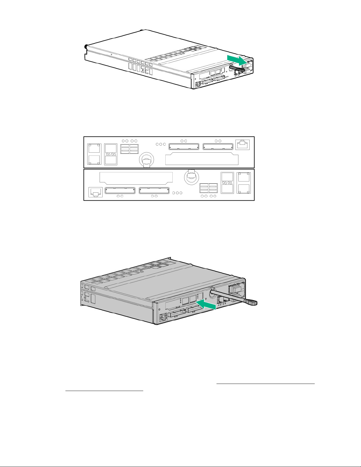
Figure 7: Extending the controller node rod
b. Confirm that the controller node is correctly oriented. In the controller node enclosure, the pair is
installed with each controller node oriented 180° from each other.
Figure 8: Orientation of a controller node pair
c. Partially install the controller node into the slot. Using two hands to grasp each side of the
replacement controller node, align it with the grooves in the slot, and slide it into the slot until it
halts against the insertion mechanism that is inside of the slot. Do not fully insert the controller
node in the slot at this time, because the cables must be reconnected before it is fully seated.
Figure 9: Partially install the controller node into the slot
13. Reconnect the cables to the controller node.
While the controller node is still only partially inserted in the slot, reconnect the cables to the
controller node.
14. Fully install and seat the controller node into the slot. See Figure 10: Fully install and seat the
controller node into the slot on page 16.
Slide in the controller node (1) while pushing in on the gray rod until it stops (2).
Service 15
If the UID LED is flashing blue after two minutes, this LED status indicates that the replacement
controller node is not properly seated, so repeat this step.
Figure 10: Fully install and seat the controller node into the slot
Once inserted, the replacement controller node powers up and goes through the automatic node-tonode rescue before joining the cluster. This process might take up to 10 minutes.
IMPORTANT: If the automatic node-to-node rescue does not start automatically, contact your
authorized service provider.
Verification
15. Verify that the controller node has joined the cluster.
Confirm that the green Status LED on the controller node is flashing in synchronization with the other
controller nodes, indicating that it has joined the cluster.
16. From the Service Console interface, verify that the State of the component and the storage system
are Normal (green).
17. After the component replacement, initiate Check Health on the storage system.
a. From the Service Console interface, select Systems.
b. Select Actions > Check health.
18. If significant time is left in the maintenance window, end the Maintenance Mode.
a. From the Service Console interface, select Systems.
b. Select Actions > Set maintenance mode.
c. To end the maintenance window associated with the replacement, click X.
The flow of support information and local notifications of system alerts will be sent to Hewlett
Packard Enterprise again.
19. Follow the return instructions provided with the replacement component.
Drive replacement
Replacing a drive—SP 4.x
This procedure is for the replacement of a drive using HPE 3PAR Service Processor (SP) 4.x.
16 Service

CAUTION:
• The replacement drive must match the failed drive exactly in terms of drive type, capacity, and
speed.
• To avoid damage to hardware and the loss of data, never remove a drive without first confirming
that the drive status/activity LED is solid amber and the UID/service LED is solid blue.
• If you require more than 10 minutes to replace a drive, install a slot-filler blank in the drive bay to
prevent overheating while you are working.
• If the storage system is enabled with HPE 3PAR Data Encryption feature, only use Federal
Information Processing Standard (FIPS) capable drives. Using a non-self-encrypting drive might
cause errors during the replacement process.
• To avoid potential damage to equipment and loss of data, handle drives carefully following
industry-standard practices and ESD precautions. Internal storage media can be damaged when
drives are shaken, dropped, or roughly placed on a work surface.
• Before installing drives into enclosures, make sure that the enclosures are free of obstructions
(such as loose screws, hardware, or debris). Inspect the drives before installing them in the
enclosure to make sure that they are not damaged.
IMPORTANT:
• This replacement procedure applies only to a drive that has failed. If a drive replacement is
needed for a drive that has not failed, contact your authorized service provider.
• If more than one drive is degraded or failed, contact your authorized service provider to
determine if the repair can be done in a safe manner, preventing downtime or data loss.
IMPORTANT: When replacing a drive that is Failed, Maintenance Mode is not required. By not
setting Maintenance Mode, alerts for other issues that might arise will continue to be sent to HPE.
Prerequisites
Order a replacement component by contacting your Hewlett Packard Enterprise authorized service
provider.
Procedure
Preparation
1. Unpack the component and place on an ESD safe mat.
2. Connect to the HPE 3PAR Service Processor.
Browse to either the IP address or hostname: https://<sp_ip_address> or https://
<hostname> .
3. Log in to the HPE 3PAR Service Processor (SP).
With the 3parcust account credentials, the Service Processor Onsite Customer Care (SPOCC)
interface displays.
4. Initiate Check Health on the storage system.
Service 17
a. From the SPOCC interface main menu, click Support in the left navigation pane.
b. From the Service Processor - Support page, under StoreServs, click Health Check in the
Action column.
A pop-up window displays a status message while the health check runs.
When running the Health Check using Internet Explorer, the screen might remain blank while
information is gathered. This process could take a few minutes before displaying results. Wait for
the process to complete and do not attempt to cancel or close the browser.
c. To review the report, click either Details or View Summary.
CAUTION: If health issues are identified during the Check Health scan, resolve these issues
before continuing. Refer to the details in the Check Health results and contact Hewlett Packard
Enterprise Support if necessary.
5. Locate information about the failed drive.
The alert notification specifies which drive is in a Failed state. Notice that the health of the storage
system will be in a Degraded state due to the failed drive.
6. Locate the drive enclosure (cage) that contains the failed drive.
From the enclosure front, locate the enclosure that has a solid amber drive status LED on the left ear
cap (bezel).
7. Remove the bezel from the enclosure front.
a. Unlock the bezel if necessary.
b. Press the release tab.
c. Rotate the bezel away from the enclosure left side.
d. Pull the bezel out from the enclosure right side.
8. Locate the failed drive by the LEDs.
CAUTION: To avoid damaging the hardware or losing data, always confirm that the drive is
ready for removal by its solid amber fault LED.
IMPORTANT: If you do not see a solid amber fault LED on the drive, it could be the data has
not been vacated yet. When the drive has failed and been spun down, the fault LED becomes
lit solid amber and only then can you proceed with removal. This process may take several
hours.
Removal
IMPORTANT: Do not remove the failed drive until you have the replacement drive ready. To prevent
overheating, do not leave the drive bay unpopulated for more than 10 minutes.
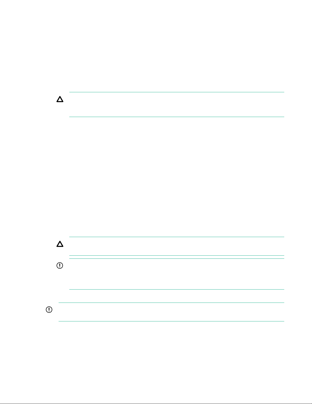
9. Remove the drive.
18 Service
a. To release the handle into the open position, pinch the latch handle to release the handle into the
open position (1).
b. Extend the latch handle (2).
c. Slide the drive out of the bay (3) and place on an ESD safe mat.
Figure 11: Removing an SFF drive
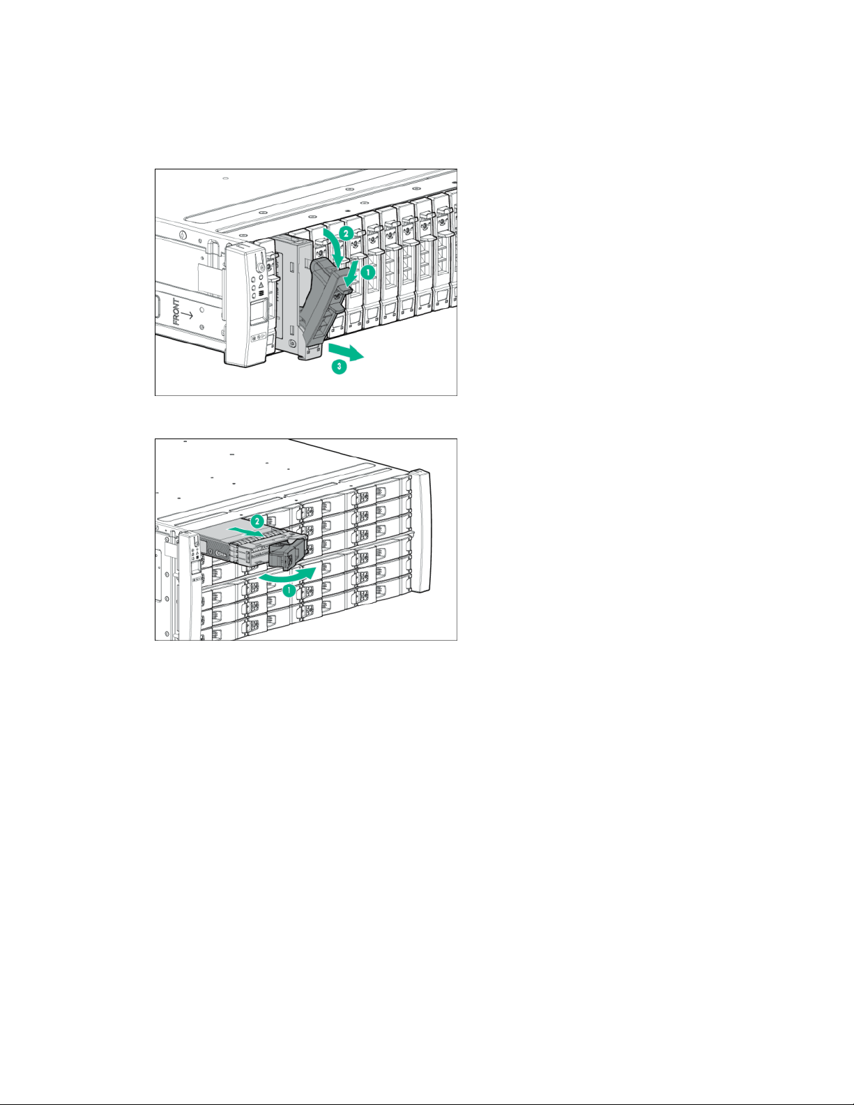
Figure 12: Removing an LFF drive
Replacement
10. Install the drive.
a. On the drive, press the release button to open the handle.
b. With the latch handle of the drive fully extended, align and slide the drive into the bay until the
handle begins to engage (1).
c. To seat the drive into the drive bay, close the handle (2).
Service 19
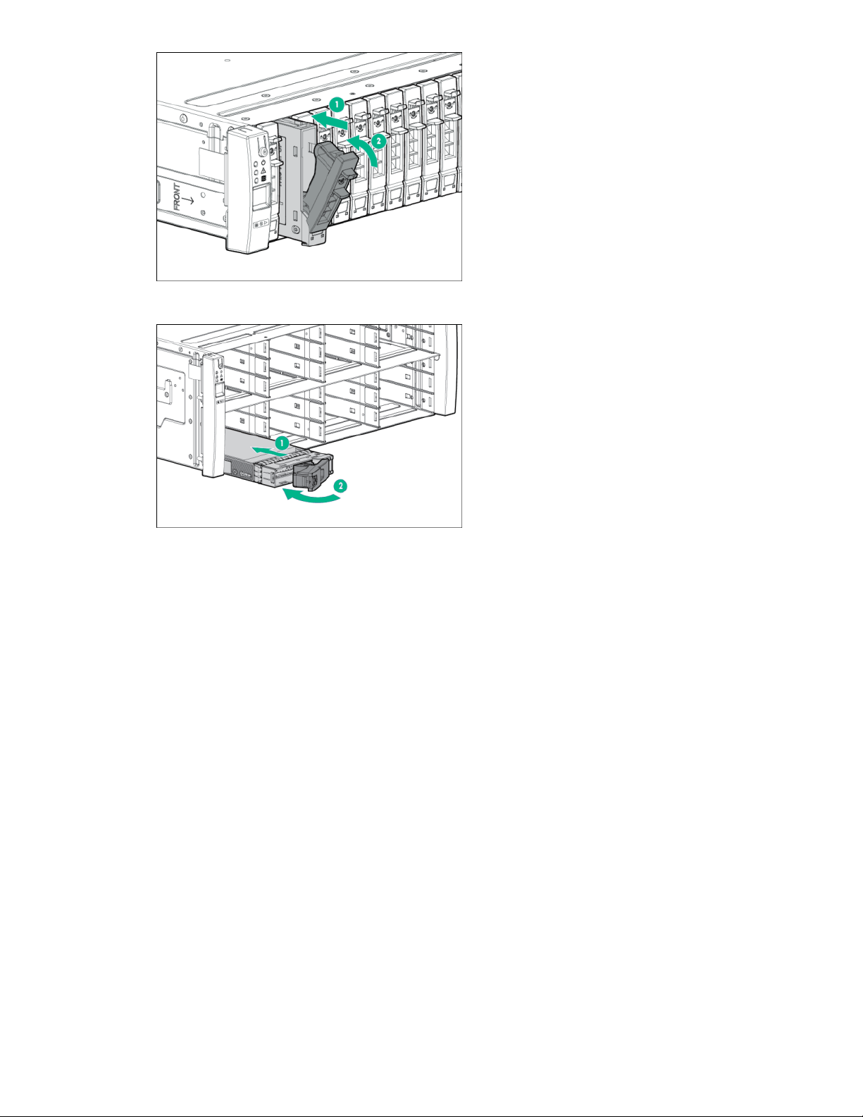
Figure 13: Installing an SFF drive
Figure 14: Installing an LFF drive
Verification
11. Observe the newly installed drive and confirm that the fault LED is off and the status LED is solid
green.
The change in the LEDs may take several minutes as the drive is prepared for use by the system.
12. Verify the state of the replacement drive.
From the SSMC interface, the drive ID that you just replaced will be removed from the list, and the
replacement drive will be assigned a new drive ID and be in a healthy state.
13. From the SPOCC interface, verify that the State for the component and the storage system are
14. After the component replacement, initiate Check Health on the storage system.
15. Install the bezel on the enclosure front.
20 Service
Normal (green).
a. From the SPOCC interface main menu, click Support in the left navigation pane.
b. From the Service Processor - Support page, under StoreServs, click Health Check in the
Action column.
a. Insert the bezel into the enclosure right side.
b. Press in the release tab.

c. Insert the bezel into the enclosure left side.
d. Lock the bezel (optional).
16. Follow the return instructions provided with the replacement component.
Replacing a drive—SP 5.x
This procedure is for the replacement of a drive using HPE 3PAR Service Processor (SP) 5.x.
CAUTION:
• The replacement drive must match the failed drive exactly in terms of drive type, capacity, and
speed.
• To avoid damage to hardware and the loss of data, never remove a drive without first confirming
that the drive status/activity LED is solid amber and the UID/service LED is solid blue.
• If you require more than 10 minutes to replace a drive, install a slot-filler blank in the drive bay to
prevent overheating while you are working.
• If the storage system is enabled with HPE 3PAR Data Encryption feature, only use Federal
Information Processing Standard (FIPS) capable drives. Using a non-self-encrypting drive might
cause errors during the replacement process.
• To avoid potential damage to equipment and loss of data, handle drives carefully following
industry-standard practices and ESD precautions. Internal storage media can be damaged when
drives are shaken, dropped, or roughly placed on a work surface.
• Before installing drives into enclosures, make sure that the enclosures are free of obstructions
(such as loose screws, hardware, or debris). Inspect the drives before installing them in the
enclosure to make sure that they are not damaged.
IMPORTANT:
• This replacement procedure applies only to a drive that has failed. If a drive replacement is
needed for a drive that has not failed, contact your authorized service provider.
• If more than one drive is degraded or failed, contact your authorized service provider to
determine if the repair can be done in a safe manner, preventing downtime or data loss.
IMPORTANT: When replacing a drive that is Failed, Maintenance Mode is not required. By not
setting Maintenance Mode, alerts for other issues that might arise will continue to be sent to HPE.
Prerequisites
Order a replacement component by contacting your Hewlett Packard Enterprise authorized service
provider.
Procedure
Preparation
1. Unpack the component and place on an ESD safe mat.
2. Connect to the service processor in the Service Console interface:
Service 21

Browse to the IP address: https://<sp_ip_address>:8443
3. Log in to the HPE 3PAR SP and enter the admin account credentials.
4. Initiate Check Health on the storage system.
a. From the Service Console interface, select Systems.
b. Select Actions > Check health.
A check of the storage system runs to ensure that there are no additional issues.
CAUTION: If health issues are identified during the Check Health, resolve these issues before
continuing. Refer to the details in the Check Health results and review the documentation.
5. Locate information about the failed drive.
a. From the Service Console interface Systems page, click the link labeled Failed from the Health
pane to see the Overview page for the component. Notice that there is an alert banner at the top
of the page that provides additional information.
NOTE: On the Health pane of the Systems page, the State is Degraded and indicates the state
of the storage system and not the state of an individual component.
b. On the Physical Drives link in the Health pane, confirm that the drive State shows Failed and
Vacated.
c. In the Health pane, select the link next to the Failed drive, and then click the Overview drop-
down menu and select Schematic.
d. On the Schematic page, hover over the failed drive and note the positioning information within
the storage system.
CAUTION: If the drive is still in a Degraded state instead of a Failed state, do not attempt to
remove the drive from the drive enclosure. A drive in a Degraded state is still vacating the
data. If you remove a drive in a Degraded state, a loss of data may occur. Wait to remove the
drive once it enters a Failed state, which indicates that the data has been vacated and the
drive is safe to replace. This process may take several hours.
6. Locate the drive enclosure (cage) that contains the failed drive.
From the enclosure front, locate the enclosure that has a solid amber drive status LED on the left ear
cap (bezel).
7. Remove the bezel from the enclosure front.
a. Unlock the bezel if necessary.
b. Press the release tab.
c. Rotate the bezel away from the enclosure left side.
d. Pull the bezel out from the enclosure right side.
8. Locate the failed drive by the LEDs.
22 Service
CAUTION: To avoid damaging the hardware or losing data, always confirm that the drive is
ready for removal by its solid amber fault LED.
IMPORTANT: If you do not see a solid amber fault LED on the drive, it could be the data has
not been vacated yet. When the drive has failed and been spun down, the fault LED becomes
lit solid amber and only then can you proceed with removal. This process may take several
hours.
Removal
IMPORTANT: Do not remove the failed drive until you have the replacement drive ready. To prevent
overheating, do not leave the drive bay unpopulated for more than 10 minutes.
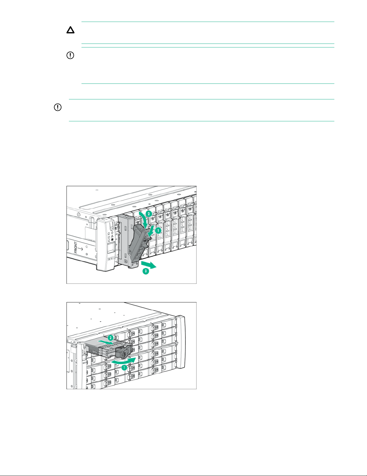
9. Remove the drive.
a. To release the handle into the open position, pinch the latch handle to release the handle into the
open position (1).
b. Extend the latch handle (2).
c. Slide the drive out of the bay (3) and place on an ESD safe mat.
Figure 15: Removing an SFF drive
Figure 16: Removing an LFF drive
Replacement
10. Install the drive.
Service 23
a. On the drive, press the release button to open the handle.
b. With the latch handle of the drive fully extended, align and slide the drive into the bay until the
handle begins to engage (1).
c. To seat the drive into the drive bay, close the handle (2).
Figure 17: Installing an SFF drive
Verification
11. Observe the newly installed drive and confirm that the fault LED is off and the status LED is solid
12. Verify the state of the replacement drive.
13. From the Service Console interface, verify that the State of the component and the storage system
14. After the component replacement, initiate Check Health on the storage system.
24 Service
Figure 18: Installing an LFF drive
green.
The change in the LEDs may take several minutes as the drive is prepared for use by the system.
From the Service Console interface, the drive ID that you just replaced will be removed from the list,
and the replacement drive will be assigned a new drive ID and be in a healthy state. The Schematic
view automatically refreshes.
are Normal (green).
a. From the Service Console interface, select Systems.
b. Select Actions > Check health.

15. Install the bezel on the enclosure front.
a. Insert the bezel into the enclosure right side.
b. Press in the release tab.
c. Insert the bezel into the enclosure left side.
d. Lock the bezel (optional).
16. Follow the return instructions provided with the replacement component.
Power cooling module or battery replacement
Replace the alternating-current power cooling module battery in a controller node enclosure—SP 5.x
This procedure is for the replacement of a battery in an alternating-current power cooling module (AC
PCM) of the controller node enclosure using HPE 3PAR Service Processor (SP) 5.x. The battery can be
replaced without replacing the entire PCM.
IMPORTANT:
• If both batteries in the power cooling modules in the same controller node enclosure have failed,
only replace one power cooling module battery at a time.
• Only one power cooling module can be serviced at a time. If another power cooling module is to
be serviced, verify that the first serviced power cooling module is healthy and functioning, and
then restart this servicing procedure from the beginning for the next power cooling module to be
serviced.
• To prevent overheating, the replacement of the power cooling module requires a maximum
service time of six minutes.
• Ensure that cables are clear of the power cooling module when installing.
IMPORTANT: Because each battery is a backup for both controller nodes in the controller node
enclosure, controller nodes 0 and 1 both report a problem with a single battery. The Qty appears as
2 in output because two controller nodes are reporting the problem. Battery 0 for controller node 0 is
in the left PCM, and battery 0 for controller node 1 is in the right side PCM (when looking at the
controller node enclosure from the rear).
Prerequisites
Only for the controller node enclosure, verify that at least one PCM Battery in each controller node
enclosure is functional before removing a PCM.
Procedure
Preparation
1. Unpack the component and place on an ESD safe mat.
2. Connect to the service processor in the Service Console interface:
Browse to the IP address: https://<sp_ip_address>:8443
Service 25

3. Log in to the HPE 3PAR SP and enter the admin account credentials.
4. Initiate a maintenance window to stop the flow of alerts to Hewlett Packard Enterprise.
a. From the Service Console interface, select Systems.
b. Select Actions > Set maintenance mode and then follow the instructions.
TIP: When you put the storage system in maintenance mode or edit the maintenance mode,
specify the duration in hours and a reason.
To edit the maintenance window, select Actions > Set maintenance mode and then click
the Edit icon next to the maintenance window.
5. Initiate Check Health on the storage system.
a. From the Service Console interface, select Systems.
b. Select Actions > Check health.
A check of the storage system runs to ensure that there are no additional issues.
CAUTION: If health issues are identified during the Check Health, resolve these issues before
continuing. Refer to the details in the Check Health results and review the documentation.
6. Review the information in the alert notification.
If notifications are enabled, information about the failed component is provided in the notification.
7. Locate the failed battery in an AC PCM by checking the LED status.
Confirm on the AC PCM that the battery fail LED is solid amber.
8. Verify that at least one battery in an AC PCM in each controller node enclosure is functional.
9. Turn off power to the AC PCM and disconnect the power cable.
a. Move the power switch to the off position.
b. Loosen the cord clamp, release the cable tie tab, and slide the cord clamp off the cable tie.
c. Disconnect the power cable, keeping the cord clamp on the power cable.
d. Secure the power cable and cable clamp.
Removal
10. Remove the AC PCM.
a. With thumb and forefinger, grasp and squeeze the PCM latch to release the handle (1).
b. Rotate the PCM release handle (2).
c. Slide the PCM out of the enclosure (3).
26 Service
d. Place the PCM on the ESD mat with the battery compartment facing up.
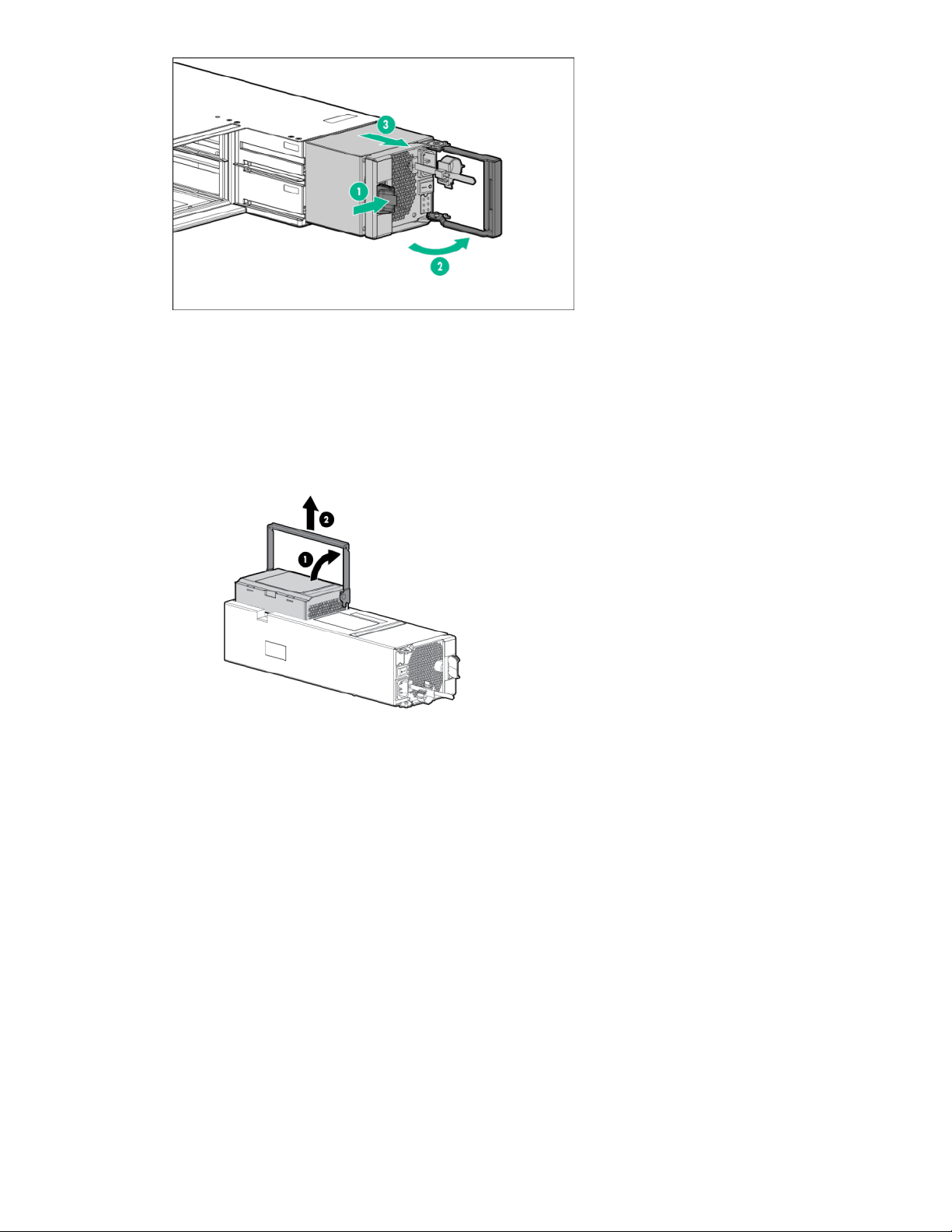
Figure 19: Removing the AC power cooling module
11. Remove the battery from the AC PCM.
a. At the back of the PCM, lift the battery release handle (1).
b. Remove the battery from the battery compartment (2).
c. Place on the ESD safe mat.
Figure 20: Removing the battery, AC power cooling module, controller node enclosure
Replacement
12. Install the battery for the AC PCM.
a. With the battery handle in the upright position, insert the replacement battery into the PCM (1).
b. Push down the handle to install (2).
When the battery is correctly seated, the battery and handle are aligned with the surface of the
PCM.
Service 27
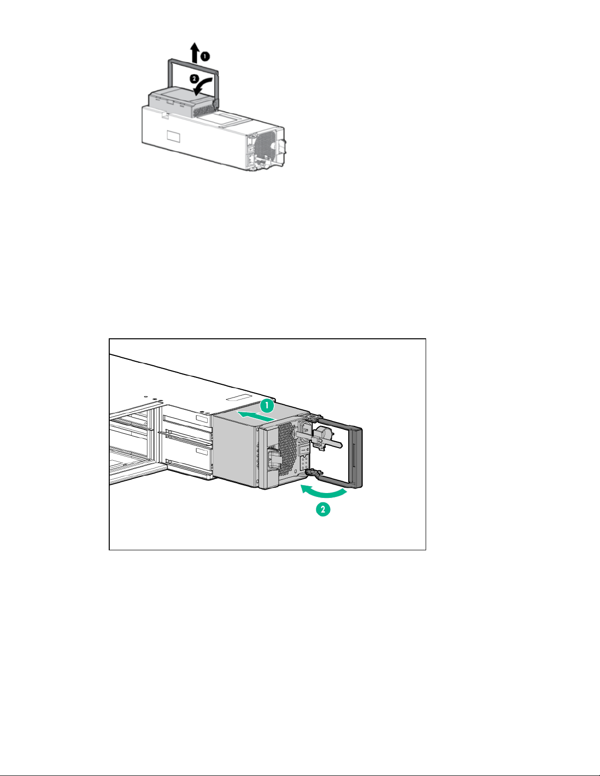
Figure 21: Installing the battery, AC power cooling module, controller node enclosure
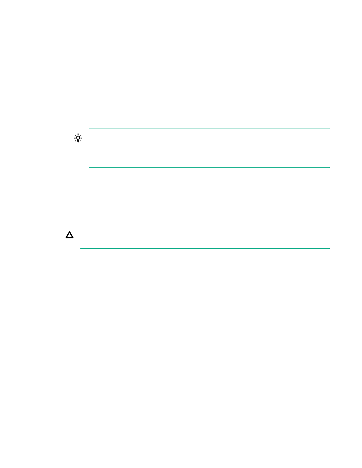
13. Install the AC PCM.
a. On the ESD mat, extend the PCM handle to the open position, and then carry it to the enclosure.
b. Slide the PCM into the enclosure and then push until the insertion mechanism starts to engage
(the handle starts to rotate).
Ensure that no cables get caught in the PCM insertion mechanism.
c. Close the handle until the latch clicks to fully seat the PCM in the enclosure.
d. Once inserted, pull back lightly on the PCM to ensure that it is properly engaged.
14. Connect the power cable and turn on the power to the AC PCM.
Verification
28 Service
Figure 22: Installing the AC power cooling module
a. Reconnect the power cable.
b. Slide the cable clamp onto the cable tie.
c. Tighten the clamp.
d. Move the power switch to the on position.

15. Verify that the replacement battery in the AC PCM has been successfully installed.
Confirm the battery good LED is solid green and the PCM OK LED is solid green.
16. From the Service Console interface, verify that the State of the component and the storage system
are Normal (green).
17. After the component replacement, initiate Check Health on the storage system.
a. From the Service Console interface, select Systems.
b. Select Actions > Check health.
18. If significant time is left in the maintenance window, end the Maintenance Mode.
a. From the Service Console interface, select Systems.
b. Select Actions > Set maintenance mode.
c. To end the maintenance window associated with the replacement, click X.
The flow of support information and local notifications of system alerts will be sent to Hewlett
Packard Enterprise again.
19. Follow the return instructions provided with the replacement component.
Replacing an alternating-current power cooling module in a controller node enclosure—SP 5.x
This procedure is for the replacement of an alternating-current power cooling module (AC PCM) in a
controller node enclosure using HPE 3PAR Service Processor (SP) 5.x.
IMPORTANT:
• Only one power cooling module can be serviced at a time. If another power cooling module is to
be serviced, verify that the first serviced power cooling module is healthy and functioning, and
then restart this servicing procedure from the beginning for the next power cooling module to be
serviced.
• To prevent overheating, the replacement of the power cooling module requires a maximum
service time of six minutes.
• Ensure that cables are clear of the power cooling module when installing.
IMPORTANT: Because each battery is a backup for both controller nodes in the controller node
enclosure, controller nodes 0 and 1 both report a problem with a single battery. The Qty appears as
2 in output because two controller nodes are reporting the problem. Battery 0 for controller node 0 is
in the left PCM, and battery 0 for controller node 1 is in the right side PCM (when looking at the
controller node enclosure from the rear).
Prerequisites
Order a replacement component by contacting your Hewlett Packard Enterprise authorized service
provider.
Service 29
Procedure
Preparation
1. Unpack the component and place on an ESD safe mat.
2. Connect to the service processor in the Service Console interface:
Browse to the IP address: https://<sp_ip_address>:8443
3. Log in to the HPE 3PAR SP and enter the admin account credentials.
4. Initiate a maintenance window to stop the flow of alerts to Hewlett Packard Enterprise.
a. From the Service Console interface, select Systems.
b. Select Actions > Set maintenance mode and then follow the instructions.
TIP: When you put the storage system in maintenance mode or edit the maintenance mode,
specify the duration in hours and a reason.
To edit the maintenance window, select Actions > Set maintenance mode and then click
the Edit icon next to the maintenance window.
5. Initiate Check Health on the storage system.
a. From the Service Console interface, select Systems.
b. Select Actions > Check health.
A check of the storage system runs to ensure that there are no additional issues.
CAUTION: If health issues are identified during the Check Health, resolve these issues before
continuing. Refer to the details in the Check Health results and review the documentation.
6. Review the information in the alert notification.
If notifications are enabled, information about the failed component is provided in the notification.
7. Locate the failed AC PCM by checking the LED status.
Confirm on the failed PCM that the AC input fail LED and DC output fail LEDs are solid amber.
8. Turn off power to the AC PCM and disconnect the power cable.
a. Move the power switch to the off position.
b. Loosen the cord clamp, release the cable tie tab, and slide the cord clamp off the cable tie.
c. Disconnect the power cable, keeping the cord clamp on the power cable.
d. Secure the power cable and cable clamp.
Removal
9. Remove the AC PCM.
30 Service
a. With thumb and forefinger, grasp and squeeze the PCM latch to release the handle (1).
b. Rotate the PCM release handle (2).
 Loading...