

HP 3PAR StoreServ 7450c, 3PAR StoreServ 7450 Planning Manual

HP 3PAR StoreServ 7450 and 7450c
Storage Site Planning Manual
Abstract
This manual provides information about installation, planning, and preparation for the HP 3PAR StoreServ 7450 and 7450c
Storage system. Use this document to obtain specific system configuration and installation guidelines for your storage system
and operating site. The described contents are intended for use by HP customers, in conjunction with the advice and assistance
of an HP Sales Representative or Systems Engineer, to plan for an HP 3PAR StoreServ 7450 and 7450c Storage system
installation.
HP Part Number: QL226-98177
Published: September 2015

© Copyright 2014, 2015 Hewlett-Packard Development Company, L.P.
The information contained herein is subject to change without notice. The only warranties for HP products and services are set forth in the express
warranty statements accompanying such products and services. Nothing herein should be construed as constituting an additional warranty. HP shall
not be liable for technical or editorial errors or omissions contained
Acknowledgments
Microsoft® and Windows® are U.S. registered trademarks of Microsoft Corporation.
Warranty
WARRANTY STATEMENT: To obtain a copy of the warranty for this product, see the warranty information website:
http://www.hp.com/go/storagewarranty
Federal Communications Commission Radio Frequency Interference Statement
WARNING: Changes or modifications to this unit not expressly approved by the party responsible for compliance could void the user’s authority
to operate the equipment.
This device complies with Part 15 of FCC Rules. Operation is subjected to the following two conditions (1) this device may not cause harmful
interference, and (2) this device must accept any interference received, including interference that may cause undesired operation.
This equipment has been tested and found to comply with the limits for a Class A digital device, pursuant to Part 15 of the FCC rules. These limits
are designed to provide reasonable protection against harmful interference when the equipment is operated in a commercial environment. This
equipment generates, uses, and can radiate radio frequency energy and, if not installed and used in accordance with the instruction manual, may
cause harmful interference to radio communications. Operation of this equipment in a residential area is likely to cause harmful interference, in
which case the user will be required to correct the interference at his or her own expense.

Contents
1 System Components and Specifications.........................................................7
HP 3PAR StoreServ 7450 Storage System Components..................................................................7
StoreServ Storage Security Feature............................................................................................10
Enhancing Security with Data Encryption..............................................................................10
Storage System Specifications...................................................................................................10
Physical Specifications........................................................................................................10
Capacity Specifications......................................................................................................11
Power and Heat Specifications.................................................................................................13
Environmental Specifications....................................................................................................13
Cable Specifications...............................................................................................................14
2 General Site Planning...............................................................................15
Customer Responsibilities.........................................................................................................15
Pre-Installation Planning...........................................................................................................15
Storage System Rack Shipping Containers.................................................................................16
Acclimatization.......................................................................................................................17
3 Structural/Environmental Considerations......................................................18
Establishing the Proper Foundation............................................................................................18
Weight and Pressure Loads.................................................................................................18
Anchoring Dimensions........................................................................................................18
Meeting Environmental Conditions............................................................................................19
Maintaining the Optimal Temperature..................................................................................19
Air Supply and Flow...........................................................................................................20
Air Cleanliness..................................................................................................................20
4 Power Requirements..................................................................................22
Electrical Requirements and Limitations......................................................................................22
Power Quality...................................................................................................................22
Voltage and Frequency Tolerance.........................................................................................22
Electrostatic Discharge.............................................................................................................22
Branch Circuits.......................................................................................................................22
Emergency Power Control........................................................................................................23
Power Distribution Units...........................................................................................................23
Power Cord Connections.........................................................................................................23
Redundant Power....................................................................................................................23
Power Cooling Modules .........................................................................................................23
5 Network, Cabling, and Connectivity...........................................................25
TCP/IP Port Assignments..........................................................................................................25
Controller Node Connections...................................................................................................26
Required Cables.....................................................................................................................27
External Cable Connections.....................................................................................................27
Internal Cable Connections......................................................................................................28
Cable Routing Options............................................................................................................28
Network Access.....................................................................................................................28
Supported Network Topologies................................................................................................28
Shared.............................................................................................................................29
Private..............................................................................................................................29
Service Processor Connectivity..................................................................................................29
6 Third-Party/Existing Rack Mounting.............................................................30
Service Installation Prerequisites................................................................................................30
Dimensional Requirements.......................................................................................................31
Contents 3

Rack Space Considerations.................................................................................................31
Maintaining Minimum Clearances.......................................................................................31
Rack Mounting Kits.................................................................................................................32
Four-Post Shelf Kit...............................................................................................................32
Redundant Power Requirements................................................................................................32
7 Support and Other Resources.....................................................................34
Contacting HP........................................................................................................................34
HP 3PAR documentation..........................................................................................................34
Typographic conventions.........................................................................................................35
Documentation feedback.........................................................................................................35
A Storage System Installation Checklist...........................................................36
Storage System Hardware Installation Checklist..........................................................................36
Storage System Software Installation Checklist............................................................................36
B File Persona Pre-Installation Checklists..........................................................39
File Persona Hardware Installation............................................................................................39
File Persona Node Installation..................................................................................................40
Authentication Settings.......................................................................................................40
Anti-Virus Settings..............................................................................................................43
Protocol Settings................................................................................................................43
File Persona Virtual File Server Installation..................................................................................44
File Persona File Share Installation.............................................................................................44
SMB Shares......................................................................................................................45
NFS Shares.......................................................................................................................46
Object Shares...................................................................................................................47
Cross Protocol Share Access................................................................................................47
File Persona Data Management................................................................................................48
Backup.............................................................................................................................48
File Store Snapshots...........................................................................................................48
Replication........................................................................................................................48
C Regulatory Compliance Notices.................................................................49
Regulatory Compliance Identification Numbers...........................................................................49
Federal Communications Commission Notice.............................................................................49
Class A Equipment.............................................................................................................49
Declaration of Conformity for Products Marked with the FCC Logo, United States Only...............49
Modification.....................................................................................................................49
Canadian Notice (Avis Canadien)............................................................................................50
Class A Equipment.............................................................................................................50
European Union Notice...........................................................................................................50
Japanese Notices...................................................................................................................50
Japanese VCCI-A Notice....................................................................................................50
Japanese Power Cord Statement..........................................................................................50
Korean Notices......................................................................................................................51
Class A Equipment.............................................................................................................51
Taiwanese Notices..................................................................................................................51
BSMI Class A Notice..........................................................................................................51
Taiwan Battery Recycle Statement.........................................................................................51
Turkish Recycling Notice..........................................................................................................51
Vietnamese Information Technology and Communications Compliance Marking.............................51
Laser Compliance Notices.......................................................................................................52
English Laser Notice...........................................................................................................52
Dutch Laser Notice.............................................................................................................52
French Laser Notice............................................................................................................52
German Laser Notice.........................................................................................................53
4 Contents

Italian Laser Notice............................................................................................................53
Japanese Laser Notice........................................................................................................53
Spanish Laser Notice..........................................................................................................54
Recycling Notices...................................................................................................................54
English Recycling Notice.....................................................................................................54
Bulgarian Recycling Notice.................................................................................................55
Czech Recycling Notice......................................................................................................55
Danish Recycling Notice.....................................................................................................55
Dutch Recycling Notice.......................................................................................................55
Estonian Recycling Notice...................................................................................................56
Finnish Recycling Notice.....................................................................................................56
French Recycling Notice......................................................................................................56
German Recycling Notice...................................................................................................56
Greek Recycling Notice......................................................................................................57
Hungarian Recycling Notice................................................................................................57
Italian Recycling Notice......................................................................................................57
Latvian Recycling Notice.....................................................................................................57
Lithuanian Recycling Notice.................................................................................................58
Polish Recycling Notice.......................................................................................................58
Portuguese Recycling Notice................................................................................................58
Romanian Recycling Notice.................................................................................................58
Slovak Recycling Notice.....................................................................................................59
Spanish Recycling Notice....................................................................................................59
Swedish Recycling Notice...................................................................................................59
Battery Replacement Notices....................................................................................................59
Dutch Battery Notice..........................................................................................................59
French Battery Notice.........................................................................................................60
German Battery Notice.......................................................................................................60
Italian Battery Notice.........................................................................................................61
Japanese Battery Notice.....................................................................................................61
Spanish Battery Notice.......................................................................................................62
Contents 5

Figures
1 Front View of HP 3PAR StoreServ 7450.................................................................................8
2 Rear View of HP 3PAR StoreServ 7450..................................................................................8
3 Front View of HP 3PAR StoreServ 7450 (Four-Node System).....................................................9
4 Rear View of HP 3PAR StoreServ 7450 (Four-Node System)......................................................9
5 Front View of HP M6710 Drive Enclosure (2U24)....................................................................9
6 Rear View of HP M6710 Drive Enclosure (2U24)....................................................................9
7 Front View of HP M6720 Drive Enclosure (4U24)..................................................................10
8 Rear View of HP M6720 Drive Enclosure (4U24)..................................................................10
Tables
1 HP 3PAR StoreServ 7450 Storage Components....................................................................11
2 Capacity Specifications....................................................................................................12
3 Power Requirements .........................................................................................................13
4 Environmental Specifications..............................................................................................13
5 Required Cables .............................................................................................................14
6 Fibre Channel Cable Usage Guidelines .............................................................................14
7 Cable Limitations for Fibre Channel Host Connectivity...........................................................14
8 Weight and Pressure Load Specifications.............................................................................18
9 Thermal Emissions of Components......................................................................................19
10 Battery Pack Technical Specifications..................................................................................24
11 TCP/IP Port Usage Table...................................................................................................25
12 Required Cables .............................................................................................................27
13 External Controller Node Connections ...............................................................................27
14 Cable Limitations for Fibre Channel Host Connectivity...........................................................28
15 SAS and Link Cable Usage Guidelines ..............................................................................28
16 Service Processor Connectivity Options...............................................................................29
17 Minimum Clearances .......................................................................................................31
18 Mounting Kits .................................................................................................................32
19 Document conventions......................................................................................................35
20 SP and Storage System Software Installation Checklist...........................................................36
21 File Persona hardware installation checklist..........................................................................39
22 File Persona Node Networking Checklist.............................................................................40
23 Authentication Settings......................................................................................................41
24 Identity Mapping.............................................................................................................42
25 Local Groups and Users....................................................................................................42
26 Local and Primary Groups.................................................................................................42
27 Anti-Virus Settings............................................................................................................43
28 NFSv4............................................................................................................................43
29 Object............................................................................................................................43
30 File Persona Virtual File Server Installation...........................................................................44
31 SMB Shares....................................................................................................................45
32 NFS Shares.....................................................................................................................46
33 Object Shares.................................................................................................................47
34 Cross Protocol Share Access..............................................................................................47
35 Backup...........................................................................................................................48
36 File Store Snapshots.........................................................................................................48
37 Replication......................................................................................................................48

1 System Components and Specifications
This chapter provides detailed system specifications for the HP 3PAR StoreServ 7450 Storage
system and serves as a quick reference for other relevant specifications that are described in more
detail in other chapters of this manual.
HP 3PAR StoreServ 7450 Storage System Components
HP 3PAR storage systems utilize a cluster-based design that incorporates sophisticated data
management and fault tolerance technologies that can meet the storage needs of smaller sites and
can easily be scaled for global organizations.
The HP 3PAR StoreServ 7450 is compatible with most industry-standard 4-post EIA 19–inch racks
with square mounting holes, including the HP Intelligent Series Rack and the HP 10000 G3 Series
Rack. The HP 3PAR StoreServ 7450 can be factory configured and shipped in a rack, or shipped
without a rack for field integration into an existing rack. The rack used for factory integration is
the HP Intelligent Series Rack.
The storage system is comprised of the following components:
• Controller nodes are components in the storage system that work to cache and manage data
and provide hosts with a coherent, virtualized view of the system. Controller nodes are located
in the rear of the node enclosure.
◦ The HP 3PAR StoreServ 7450 Storage system can include two nodes or four nodes (Nodes
0 and 1 on the lower controller and Nodes 2 and 3 on the upper controller in a system
with four nodes).
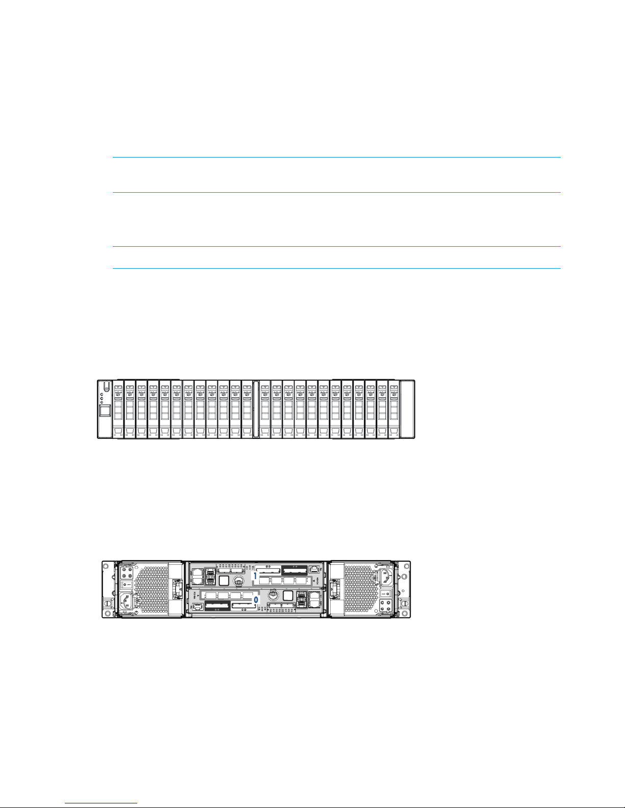
◦ The HP 3PAR StoreServ 7450 (two-node) Storage enclosures hold up to 24, 2.5 inch
small form-factor (SFF) Serial Attached SCSI (SAS) disk drives arranged vertically in a
single row. The back of the enclosure includes two 764 W power cooling modules (PCM)
and two controller nodes.
◦ The HP 3PAR StoreServ 7450 (four-node) Storage enclosure holds up to 48, 2.5 inch SFF
SAS disk drives arranged in two vertical rows. The back of the enclosure includes four
764 W PCMs and four controller nodes.
• Drive enclosures hold an array of disk drives. These are intelligent, compact, extremely dense
storage units, where each is capable of holding a large numbers of disk drives in a small rack
space (EIA-standard rack units).
◦ The HP M6710 Drive Enclosure (2U24) holds up to 24, 2.5 inch small form-factor (SFF)
SAS Solid State Disks (SSD) disk drives, installed vertically in a single row at the front of
the enclosure. The back of the enclosure contains two 580 W PCMs and two I/O modules.
◦ The HP M6720 Drive Enclosure (4U24) holds up to 24, 3.5 inch large form-factor (LFF)
SAS SSD disk drives, installed horizontally with four columns of six disk drives. The back
of the enclosure contains two 580 W PCMs and two I/O modules.
• I/O Modules connect the controller nodes to the drives using SAS cables, enabling the transfer
of data between the nodes, the drives, PCMs, and enclosures. The I/O modules are located
at the rear of the drive enclosure and are numbered 0 to 1 from bottom to top. There are two
I/O modules per enclosure.
• The HP 3PAR StoreServ 7450 Storage system can include an HP 3PAR Service Processor (SP)
or can use a Virtual Service Processor (VSP). If your configuration includes an SP, it will be
located at the bottom of the rack under the enclosures and above the power distribution units
(PDU).
HP 3PAR StoreServ 7450 Storage System Components 7
• Power Cooling Module is an integrated power supply, battery, and cooling fan. There are
two types of PCMs:
◦ The 580 W is used in the drive enclosures and does not include a battery.
◦ The 764 W (includes a replaceable battery) is used in the node enclosures. The PCMs
are located at the rear of the system, on either side of an enclosure.
There are two PCMs per enclosure that are numbered from 0 to 1, from bottom to top and
left to right.
NOTE: In the HP M6720 Drive Enclosure, there are two PCMs that are diagonally from one
another and the remaining PCM slots are filled with blank panels.
• The Power Distribution Units (PDU) are housed in the HP G3 rack. There are two Power
Distribution Units (PDUs) that are mounted horizontally at the bottom of the rack and are
numbered 0 to 1 from bottom to top.
NOTE: Depending on the configuration, PDUs can also be mounted vertically.
The various drive enclosure and controller nodes of the HP 3PAR StoreServ 7450 Storage system
are shown.
Figure 1 Front View of HP 3PAR StoreServ 7450
Figure 2 Rear View of HP 3PAR StoreServ 7450
8 System Components and Specifications
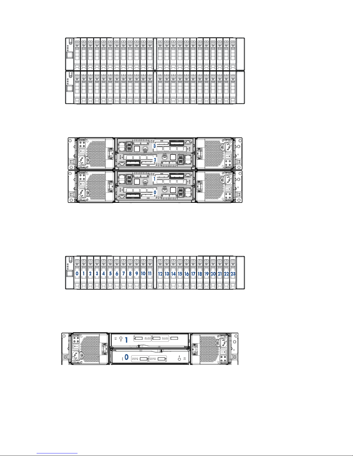
Figure 3 Front View of HP 3PAR StoreServ 7450 (Four-Node System)
Figure 4 Rear View of HP 3PAR StoreServ 7450 (Four-Node System)
Figure 5 Front View of HP M6710 Drive Enclosure (2U24)
Figure 6 Rear View of HP M6710 Drive Enclosure (2U24)
HP 3PAR StoreServ 7450 Storage System Components 9
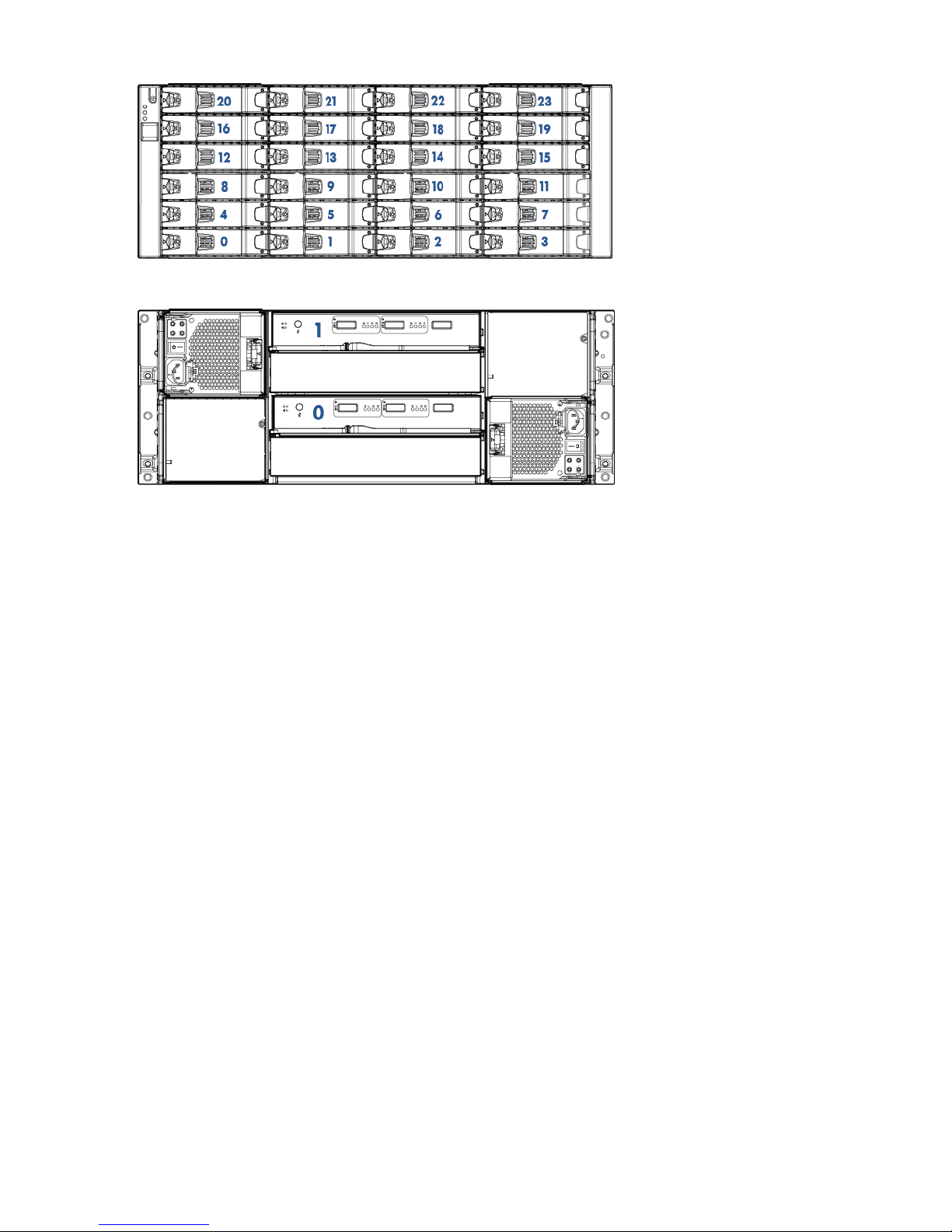
Figure 7 Front View of HP M6720 Drive Enclosure (4U24)
Figure 8 Rear View of HP M6720 Drive Enclosure (4U24)
StoreServ Storage Security Feature
HP 3PAR Data Encryption security feature allows you to encrypt all specifically formatted hard
drives on the storage system with an authentication key and the use of Self Encrypting Drives (SEDs).
Enhancing Security with Data Encryption
When a Data Encryption license is registered, you must manually enable the encryption feature
on the system. When the encryption feature is enabled successfully, all the drives in the system
become automatically set in an encrypted state. You can review the encryption status of individual
hard disk drives within the system Summary tab of the HP 3PAR Management Console.
This feature allows you to perform the following encryption-related tasks:
• Check encryption status
• Enable encryption
• Back up an authentication key
• Restore an authentication key
• Generate a new key
• Recover a key
For more information about enabling the feature, see the HP 3PAR Management Console 4.4 or
later User Guide.
Storage System Specifications
The 7450 can be configured with two nodes or four nodes. The maximum number of supported
drive enclosures varies according to the number and type of controller nodes used by the system.
Physical Specifications
The following table lists system specifications. Specifications are subject to change without notice.
10 System Components and Specifications

Table 1 HP 3PAR StoreServ 7450 Storage Components
7450 Drive/Node Integrated Enclosure
24 Small Form-Factor (SFF) drive slotsConfiguration
2 Controller Nodes
PCIe slots (one per node) Fibre Channel HBA or iSCSI CNA
2 host FC ports
2 disk expansion SAS ports
1 1Gb Ethernet RCIP port
1 1Gb Ethernet management port
2 interconnect link ports
1 console port
3.46” (87.9mm) x 19”(483mm) x 26.6” (674.9mm)Dimensions (width x height x depth)
48.7lbs/22.1kg (no HDD); 65.5lbs/29.7kg (max)Weight
100-240 VAC 50-60HzPower
1+1 Redundant Hot Swap PCM with integrated battery
and cooling fan
112 CFMAir Flow
Front: 30” , Sides: None, Rear: 24”Service Clearances
Front: NoneCabling
Rear: Data/Power
M6710 / M6720 Drive Enclosures
2 I/O modulesConfiguration
4 SAS Ports
8 Ports
3.46” (87.9mm) x 19” (483mm) x 24.8” (630mm)M6710 Dimensions (width x height x depth)
6.89” (175mm) x 19” (483mm) x 24.9” (631.3mm)M6720 Dimensions (width x height x depth)
100-240 VAC 50-60HzPower
1+1 Redundant Hot Swap PCM with integrated cooling
fan
105 CFMM6710 Airflow
109 CFMM6720 Airflow
Front: 30” , Sides: None, Rear: 24”Service Clearances
Front: NoneCabling
Rear: Data/Power
Capacity Specifications
The following table lists system capacity and configuration details.
Storage System Specifications 11

NOTE: SSDs have a limited number of writes that can occur before reaching the SSD's write
endurance limit. This limit is generally high enough so wear out will not occur during the expected
service life of an HP 3PAR StoreServ under the great majority of configurations, I/O patterns, and
workloads. HP 3PAR StoreServ tracks all writes to SSDs and can report the percent of the total
write endurance limit that has been used. This allows any SSD approaching the write endurance
limit to be proactively replaced before they are automatically spared out. An SSD has reached the
maximum usage limit once it exceeds its write endurance limit. Following the product warranty
period, SSDs that have exceeded the maximum usage limit will not be repaired or replaced under
HP support contracts.
Table 2 Capacity Specifications
7450 (Four Nodes)7450 (Two Nodes)Feature
42Number of controller nodes
32GB16GBControl cache
32GB16GBData cache
8–244–12Host ports
0-80-410 Gb/s iSCSI host ports
8–244–12Fibre Channel host ports
1
12–4806–240Number of drives
1
2.4TB to 864TB1.2TB to 432TBRaw capacity (approximately)
1
RAID 0, 1, 5, 6RAID 0, 1, 5, 6RAID levels
2:1 - 8:12:1 - 8:1RAID 5 data to parity ratios
Minimum physical drives to create
RAID 5 volume: 8
4:2; 6:2; 8:2; 10:2; 14:24:2; 6:2; 8:2; 10:2; 14:2RAID 6 data to parity ratios
Base RAID sets: 12 drives
Minimum physical drives to create
RAID 6 volume: 12
100 GB SSD, 200 GB SSD, 400 GB
SSD, 480 GB SSD, 920 GB SSD
100 GB SSD, 200 GB SSD, 400 GB
SSD, 480 GB SSD, 920 GB SSD
Drive capacities (in approximate GB)
1
Number of drive enclosures
2
0–180–9HP M6720 (4U24)/DC1
0–180–9HP M6710 (2U24)/DC2
1
Levels, ratios, and capacities are all mixable within the same storage system. 1 GB=1,000,000,000 bytes.
2
A single drive enclosure holds up to 24 drives in both 4U and 2U chassis within an EIA-standard rack.
12 System Components and Specifications

Power and Heat Specifications
The following table lists the electrical power requirements.
Table 3 Power Requirements
Transactional (watts/BTU/hr)Idle (watts/BTU/hr)Component
398 W / 1357236 W / 803Node Pair, no drives, no add-on
host adapters
32.6 / 11124 W / 81.724-port 8 Gb/s Fibre Channel
Adapter
40 W / 136.434 W / 115.772-port 10 Gb/s iSCSI/FCoE
Adapter
150 / 512 (average)150 / 512 (average)HP M6710 2.5 inch 2U SAS Drive
Enclosure, no drives
164 / 559 (average)164 / 559 (average)HP M6720 3.5 inch 4U SAS Drive
Enclosure, no drives
3.9 / 13.31.4 / 4.8100 GB SLC SSD
3.9 / 13.31.4 / 4.8200 GB SLC SSD
7.5 / 12.62.2 / 3.7400 GB SLC SSD
5.5 / 18.72.2 / 7.49480 GB SLC SSD
5.2 / 17.82.0 / 6.7920 GB SLC SSD
7.1 / 24.43.2 / 11480 GB cMLC SSD
8.9 / 30.53.5/ 11.91920 GB cMLC SSD
NOTE: Refer to “Power Requirements” (page 22) for complete details.
Environmental Specifications
The operating site must comply with the following environmental specifications.
Table 4 Environmental Specifications
10,000ft/ 3,024m OperationalAltitude
40,000ft/ 12,192m Shipping
Operating: 41–104° F (5–40° C) - Reduce rating by 1° F for each 1000 ft altitude (1.8°
C/1,000 m)
Temperature
Non–operating: 32–203° F (0–95° C)
32–140° F (0–60° C)Shipping Temperature
10–90% non-condensingHumidity
10–90% non-condensingShipping Humidity
Operating: 0.25 G, Sine, 5-500 Hz; 0.15 Grms Random, 5-100 HzVibration
Non-operating: 0.5G, Sine, 5-500 Hz
Operating: 2 G, 11ms, half-sineShock
Non-operating: 10 G, 11ms, half-sine
For more information, refer to “Structural/Environmental Considerations” (page 18) for details.
Power and Heat Specifications 13

Cable Specifications
The following table lists the types of cables commonly required for the installation of a storage
system.
Table 5 Required Cables
Connector TypeCable Type
RJ-45Ethernet (Category 5) 3 cables minimum with 3 static IPs:
• IP=SP
• IP=StorageServ
• IP For service (node rescue example)
LC-LCMulti-mode Fibre Channel Requires 50 micron OM3 cables
for 8–10Gb/s speeds.
Mini SAS SFF8088SAS cables for drive cage connections: 1M, 2M, and 6M
The following table lists the typical Fibre Channel cable lengths required for a given type of
connection.
Table 6 Fibre Channel Cable Usage Guidelines
Used For:Cable Length
Connecting Drive enclosures and controller nodes in the
same rack.
6m
Cabling between racks. Always round up to the nearest
size.
10m
25m
50m
100m
The following table lists the maximum supported Fibre Channel cable length based on the cable
size and port speed.
Table 7 Cable Limitations for Fibre Channel Host Connectivity
Cable Length LimitSpeedCable Size
300 meters4–, 8–, or 10 Gb/sOM3 and OM4
NOTE: Refer to “Network, Cabling, and Connectivity” (page 25) for more details on cable
requirements and configurations.
14 System Components and Specifications

2 General Site Planning
Successful installation of the HP 3PAR StoreServ 7450 Storage system requires careful planning
and supervision in collaboration with authorized HP representatives. Proper planning will help
provide for a more efficient installation and greater reliability, availability, and serviceability. The
chapter includes general recommendations for physical planning and site preparation for the
storage system installation.
Customer Responsibilities
The customer must provide any hardware required to host the remote support software when
deploying a Virtual Service Processor. For scheduled service calls, the customer shall make the
Virtual Service Processor available to HP for remedial activities at the agreed-upon time. The
customer is responsible for maintaining the appropriate HP 3PAR Remote Support Technology with
a secure connection to HP and any passwords required to access the local network and Virtual
Service Processor. The customer is responsible for providing all necessary resources in accordance
with the HP 3PAR Service Processor Release Notes in order to enable the delivery of the service
and options. Please contact a local HP representative for further details on requirements,
specifications, and exclusions.
Pre-Installation Planning
When planning and preparing for the installation of a storage system, you assume the following
responsibilities:
• Providing suitable space for unpacking, installing, and operating the storage system
• Maintaining the proper environmental conditions for the storage system
• Providing adequate power facilities for the storage system
• Supplying the network connections and external cabling required by the storage system
• Enabling the appropriate HP 3PAR remote support strategy
NOTE: Electronic equipment has special packing for shipping and receives special handling
during transportation. HP is responsible for the manufacturing environment and packaging for
shipping.
For optimal performance at a specific location, storage systems require controlled environmental
conditions that can best be facilitated through raised flooring and under-floor air conditioning. It
is the customer's responsibility to monitor this environment to ensure continued conformance with
the recommended environmental specifications. Refer to “Structural/Environmental Considerations”
(page 18) for specific information concerning server room environments.
Adequate power is necessary for the reliable functioning of electronic equipment and for the safety
of the customer's installation. The customer is responsible for procuring, installing, and maintaining
adequate power to the equipment. Refer to “Power Requirements” (page 22) for input electrical
power and grounding requirements.
All pre-installation activities should be scheduled and completed before the equipment is delivered.
The pre-installation process includes the following:
• Hardware configuration planning, such as system component layout and drive allocation
• Networking and cabling topics, such as storage system and SP network topologies, internal
system cabling configurations, and cabling of connected host computers
Customer Responsibilities 15

The following are suggested site planning tasks to be completed prior to the delivery and installation
of the selected storage system.
• Prepare a preliminary layout of the subsystem installation.
• Review the power and the heating, ventilation, and air-conditioning (HVAC) requirements.
• Order any additional support equipment indicated by the power and HVAC review.
• Work with the appropriate HP representative to ensure that all system units in the specified
configuration and all cables of the required length have been ordered.
• Make a final layout of the installation and review the layout with your HP representative.
• Select key personnel and arrange for training with your HP representative.
• Verify the electrical service wiring has been installed at the predetermined location before
installing the storage system. Refer to the respective product specifications for detailed
requirements.
• Verify any additional support equipment is properly installed and operational.
Prior to installation, review the packaging to make sure the goods have not been tampered with.
When unpacking the equipment, verify the delivered shipment of all the equipment is correct. Refer
to the packing slip and the SKUs with the shipment. Complete the installation checklist. See “Storage
System Installation Checklist” (page 36). Also, prepare the following checkpoints with your local
Sales Representative or Systems Engineer:
• Contact information for customer personnel and for HP technical sales, support, and service
personnel
• Implementation project plan
• Configuration information for the storage system to be installed, including system configuration
diagrams
• Shipping and delivery details and requirements
• Management workstation, SP, and network information
• Description of the environment
• Volume and RAID level planning information
• Additional notes and comments about installation
• Current support matrix
• System technical specifications
• Systems Acceptance Certificate
Storage System Rack Shipping Containers
A separate shipping container holds each storage system rack. The drive and node enclosure
shipping containers hold a maximum of 24 drives. Examine the delivered package for obvious
damage or signs of tampering and notify both HP and the carrier of any issues.
Shipping container measurements are as follows:
• Rack crate container: 85.35 x 50.87 x 35.43 inch (216.80 x 129.20 x 90 cm)
Approximate shipping weight: 1606 lb (728 kg)
• Drive enclosure container: Height 13 inch (33.1 cm) x Width 11 inch (28 cm) x Depth 27
inch (68.6 cm)
Approximate shipping weight: 33.8 lb (15.4 kg)
16 General Site Planning

• Disk drive magazine container: Height 38 inch (96.5 cm) x Width 29 inch (73.6 cm) x Depth
34 inch (86.4 cm)
Approximate shipping weight: 392 lb (177.8 kg)
• Node enclosure container: Height 30 inch (76.2 cm) x Width 35 inch (88.9 cm) x Depth 45
inch (114.3 cm)
Approximate shipping weight: 618 lb (280.3 kg)
When the equipment arrives, you must make sure that there is enough room to unload and unpack
the storage system.
The specific amount of space you will need to unpack the storage system is based on the dimensions
of the container, the ramp, and the room required to access the storage system so that it can be
moved to its placement destination.
NOTE: See “Structural/Environmental Considerations” (page 18) for more information on placing
the storage systems and reserving room for service access.
Acclimatization
Storage systems are shipped or stored at extreme temperatures and may require time to adjust to
operating temperatures before startup. The maximum acceptable rate of temperature change for
a non-operating system is 36° F/hour (20° C/hour). The storage system requires time to acclimatize
to new environmental conditions before being powered on. During that time, it is possible to
proceed with the physical installation of the storage system. However, the storage system may
need at least 24 hours to acclimatize to a new environment prior to completing the full system
installation. If condensation is present even after the 24-hour acclimatization period, it is necessary
to wait until all condensation has evaporated before completing the power-on sequence.
Acclimatization 17

3 Structural/Environmental Considerations
Consider the following when choosing or designing your facilities for the storage system:
• Equipment location and layout that allows efficient use, easy maintenance, and future
expansion.
• Facility construction that provides a suitable operating environment, sufficient power, and
adequate protection from fire, contamination, or other hazards.
• Suitable temperatures and appropriate air quality that is free from environmental contaminants.
The customer is responsible for maintaining the room environment according to the recommended
specifications. Environmental conditions for the room and under the floor must be maintained within
the acceptable limits to prevent any adverse impact on performance and reliability. The installation
environment should be monitored on a regular basis to ensure continued conformance to
recommended environmental specifications. The customer may request assistance from an HP 3PAR
representative for help with analyzing the site location and environment to make appropriate
recommendations.
For information on rack requirements and considerations, see the Best practices for HP Intelligent
Series Rack Family white paper.
Establishing the Proper Foundation
Weight and Pressure Loads
Depending on the configuration, a storage system weighs up to 2000 lb (907 kg). The following
table lists the maximum weights and pressure loads per leveling foot for storage system racks. Use
these values to approximate the structural support required by a storage system rack.
Table 8 Weight and Pressure Load Specifications
SKU
Max Ship Weight (lb)
w /Pack
Max Racked Weight
(lb) Unit + MountsDimensions (inches)Rack
QR482A89 lb65 lb37.65x23.63x11.002 Node (QR482A,
QR484A, QR483A)
QR483A71 lb51 lb35.88x23.63x11.002U Drive Enclosure
(QR490A)
QR484A160 lb129 lb36.77x23.63x14.504 Node (QR485A)
QR485A116 lb88.5 lb36.77x23.63x14.504U Drive Enclosure
(QR491A)
QR490A1.3 lb0.7 lb12.88x8.68x5.81Large Form-Factor
HDD
QR491A2.7 lb1.9 lb12.75x7.25x5.12Small Form-Factor
HDD
NOTE: The example uses nominal numbers to simplify calculations.
Anchoring Dimensions
Some installations may require the storage systems to be anchored to the floor for better stability,
especially in active seismic locations. The HP Tie Down Option Kit enables you to anchor an
Intelligent Series Rack to the floor in geographical areas that are prone to seismic activity, thereby
meeting international building code guidelines. This product provides a solution to help avoid
damage or serious injury in the event of building or floor movement.
18 Structural/Environmental Considerations

NOTE: For information on options available for the Intelligent Series Rack, refer to the Rack
Options Catalog at www.hp.com/go/rackandpower.
For information on rack requirements and considerations, see the Best practices for HP Intelligent
Series Rack Family white paper.
Meeting Environmental Conditions
HP recommends that you maintain a controlled environment with a high degree of cleanliness,
close control of temperature and humidity, and infrequent access by personnel.
CAUTION: The storage system operating environment must be free from continuous vibration
and from dust and other environmental contaminants.
Maintaining the Optimal Temperature
The level of cooling required for the storage systems is quite different from the air-conditioning
used in offices. Air conditioning systems for comfort are designed for the lower heat and higher
moisture generated by the human body. In contrast, equipment has high heat output that is
moisture-free (sensible heat). In comfort systems, sensible heat normally produces 60–70% of the
load, whereas the dry heat of electronic equipment produces a sensible heat ratio of over 95%.
Prior to installation, verify the operating site is equipped with a cooling system that can support
all thermal emissions.
Proper site layout is critical to ensure the ambient temperature near the intake of the system does
not rise beyond the system specifications. Exceeding the maximum ambient temperature for any
period negatively affects the reliability and performance of the system. Continued operation for
extended periods under such conditions might actually cause the system to shut down.
CAUTION: Heated air from nearby equipment should not exhaust into the front of the storage
system.
Use the following average and maximum thermal emissions of storage system components to
estimate the cooling requirements for a storage system based on a specific system configuration.
Table 9 Thermal Emissions of Components
Maximum Thermal EmissionsAverage Thermal EmissionsComponent (Fully Populated)
3,004 BTU/hr (757 Kcal/hr)2,164 BTU/hr (545.3 Kcal/hr)Controller node (pair)
1
4,973 BTU/hr (1,253.2 Kcal/hr)3,657 BTU/hr (921.6 Kcal/hr)Drive enclosure (single)
9,946 BTU/hr (2,506.4 Kcal/hr)7,314 BTU/hr (1,843.2 Kcal/hr)Drive enclosure (pair)
2
1
Controller nodes can only be installed in pairs.
2
Storage systems require a minimum of two drive enclosure. However, additional drive enclosure can be installed
individually.
Storage systems can tolerate temperature and humidity fluctuations if the specified guidelines are
understood and followed. Exposure to conditions outside the specified ranges may damage the
system or its components.
Before a system is powered on, the air entering the subsystem must be clean and within the ranges
specified for temperature and humidity. The room humidity must be kept sufficiently low to prevent
condensation on or within the subsystem, and must never exceed the limit specified in the subsystem
environmental requirements tables, including transient humidity. The system must never be exposed
to conditions that could cause internal condensation to occur within the subsystem.
The air conditioning units should have controls monitoring thermal conditions underneath the floor.
Humidification is normally required to replace moisture removed during the cooling process. The
Meeting Environmental Conditions 19
 Loading...