

Page 1

HPE 3PAR StoreServ 7000 Storage
Service and Upgrade Guide ———
Customer Edition
HPE 3PAR OS 3.2.2 and 3.3.1
HPE SP 4.x and 5.x
Abstract
This Hewlett Packard Enterprise (HPE) guide provides information and instructions to guide
you in servicing and upgrading the HPE 3PAR StoreServ 7200, 7200c, 7400, 7400c, 7440c,
7450, and 7450c Storage systems without the assistance of an authorized service provider. If
assistance is needed, contact your HPE Sales Representative or HPE Partner.
Part Number: QL226-99811
Published: December 2017
Page 2

©
Copyright 2014-2017 Hewlett Packard Enterprise Development LP
Notices
The information contained herein is subject to change without notice. The only warranties for Hewlett
Packard Enterprise products and services are set forth in the express warranty statements accompanying
such products and services. Nothing herein should be construed as constituting an additional warranty.
Hewlett Packard Enterprise shall not be liable for technical or editorial errors or omissions contained
herein.
Confidential computer software. Valid license from Hewlett Packard Enterprise required for possession,
use, or copying. Consistent with FAR 12.211 and 12.212, Commercial Computer Software, Computer
Software Documentation, and Technical Data for Commercial Items are licensed to the U.S. Government
under vendor's standard commercial license.
Links to third-party websites take you outside the Hewlett Packard Enterprise website. Hewlett Packard
Enterprise has no control over and is not responsible for information outside the Hewlett Packard
Enterprise website.
Acknowledgments
Intel®, Itanium®, Pentium®, Intel Inside®, and the Intel Inside logo are trademarks of Intel Corporation in
the United States and other countries.
Microsoft® and Windows® are either registered trademarks or trademarks of Microsoft Corporation in the
United States and/or other countries.
Adobe® and Acrobat® are trademarks of Adobe Systems Incorporated.
Java® and Oracle® are registered trademarks of Oracle and/or its affiliates.
UNIX® is a registered trademark of The Open Group.
Page 3

Contents
Preparing for service or upgrade of the storage system.................... 6
Service of the hardware components................................................... 7
Upgrade of the storage system........................................................... 31
Service and upgrade videos......................................................................................................... 6
Safety and regulatory compliance.................................................................................................6
Controller Node replacement—Two-node system only—Optional CSR component.................... 7
Replacing a Controller Node—Two-node system only—SP 4.x........................................ 8
Replacing a Controller Node—Two-node system only—SP 5.x.......................................11
Drive replacement—Mandatory CSR component.......................................................................15
Replacing a Drive—SP 4.x...............................................................................................16
Replacing a Drive—SP 5.x...............................................................................................20
SFP Transceiver Replacement—Mandatory CSR component................................................... 25
Replacing an SFP Transceiver—SP 4.x.......................................................................... 26
Replacing an SFP Transceiver—SP 5.x.......................................................................... 28
Drives upgrade—Mandatory CSU component............................................................................31
Guidelines for allocating and loading Drives.................................................................... 32
Guidelines for adding more Drives to the storage system............................................... 35
Upgrading to add Drives—SP 4.x.................................................................................... 35
Upgrading to add Drives—SP 5.x.................................................................................... 39
More information for service and upgrade of the storage system...44
Accounts and credentials for service and upgrade..................................................................... 44
Time-based password (strong password)........................................................................ 44
Encryption-based password (strong password)............................................................... 44
HPE 3PAR Service Processor accounts for service and upgrade................................... 44
Setting time-based or encryption-based password option from the SP 5.x SC.....47
Generating the encryption-based ciphertext from the SP 5.x SC..........................48
Setting time-based or encryption-based password option from the SP 5.x TUI....48
Generating the encryption-based ciphertext from the SP 5.x TUI.........................49
Storage system accounts for service and upgrade.......................................................... 49
Setting time-based or encryption-based password option for a storage
system account......................................................................................................50
Generating the encryption-based ciphertext for a storage system account.......... 50
Regenerating the encryption-based ciphertext for a storage system account...... 51
Alert notifications for the storage system—SP 5.x......................................................................51
Browser warnings........................................................................................................................52
Controller Node rescue—Automatic Node-to-Node Rescue.......................................................52
Controller Node shutdown.......................................................................................................... 52
Shutting down a Controller Node—SP 4.x....................................................................... 53
Shutting down a controller node from the SC interface....................................................53
HPE 3PAR Service Processor.................................................................................................... 53
Firewall and Proxy server configuration........................................................................... 54
Connection methods for the SP....................................................................................... 55
Connecting to the physical SP from a laptop........................................................ 56
Contents 3
Page 4

Interfaces for the HPE 3PAR SP......................................................................................56
HPE 3PAR StoreServ Management Console............................................................................. 57
Connection method for the SSMC................................................................................... 58
Interfaces for the storage system from the SSMC........................................................... 58
Spare part number...................................................................................................................... 58
Troubleshooting.................................................................................... 59
Troubleshooting issues with the storage system........................................................................ 59
Alerts issued by the storage system................................................................................ 59
Alert notifications—SP 4.x.....................................................................................59
Alert notifications—SP 5.x.....................................................................................59
Collecting log files............................................................................................................ 60
Collecting the SmartStart log files—SP 4.x........................................................... 60
Collecting SP log files—SP4.x.............................................................................. 61
Collecting SP log files—SP 5.x............................................................................. 61
Troubleshooting issues with the components............................................................................. 62
Components functions..................................................................................................... 62
alert ...................................................................................................................63
ao ......................................................................................................................... 63
cabling .............................................................................................................. 64
cage .....................................................................................................................65
cert .....................................................................................................................70
dar ....................................................................................................................... 70
date .....................................................................................................................71
file .....................................................................................................................72
fs ......................................................................................................................... 74
host .....................................................................................................................75
ld ......................................................................................................................... 76
license .............................................................................................................. 79
network .............................................................................................................. 80
pd ......................................................................................................................... 81
pdch .....................................................................................................................85
port .....................................................................................................................87
qos ....................................................................................................................... 90
rc ......................................................................................................................... 91
snmp .....................................................................................................................92
sp ......................................................................................................................... 92
task .....................................................................................................................93
vlun .....................................................................................................................94
vv ......................................................................................................................... 95
Controlled thermal shutdown........................................................................................... 95
Parts catalog..........................................................................................97
Bezels, Blanks, and Cables parts list..........................................................................................97
Controller Node Enclosure parts list........................................................................................... 98
Drive Enclosure parts list.......................................................................................................... 103
Service Processor parts list.......................................................................................................109
Component identification................................................................... 111
Adapters (optional).................................................................................................................... 111
Adapter—Four-Port 16 Gb FC Host PCIe Adapter.........................................................112
Adapter—Two-Port 10 Gb iSCSI/FCoE CNA Host PCIe Adapter.................................. 112
4 Contents
Page 5

Adapter—Two-Port 10 GbE NIC Host PCIe Adapter......................................................113
Adapter—Four-Port 1 GbE NIC Host PCIe Adapter.......................................................113
Controller Node......................................................................................................................... 114
Controller Node Enclosure rear view.........................................................................................116
Drives........................................................................................................................................ 117
Enclosures front view................................................................................................................ 117
Expansion Drive Enclosure rear view........................................................................................119
I/O Module.................................................................................................................................120
Power Cooling Module—Controller Node Enclosure................................................................ 121
Power Cooling Module—Drive Enclosure.................................................................................122
Power Distribution Units............................................................................................................123
Service Processor.....................................................................................................................123
Component LEDs................................................................................ 124
Controller Node LEDs............................................................................................................... 124
Drive LEDs................................................................................................................................129
Adapter—Four-Port 16 Gb FC Host PCIe Adapter LEDs......................................................... 130
Adapter—Two-Port 10 Gb iSCSI/FCoE CNA Host PCIe Adapter LEDs...................................131
Adapter—Four-Port 1 GbE NIC Host PCIe Adapter LEDs....................................................... 131
Adapter—Two-Port 10 GbE NIC Host PCIe Adapter LEDs...................................................... 132
I/O Module LEDs.......................................................................................................................133
Power Cooling Module LEDs—Controller Node Enclosure...................................................... 134
Power Cooling Module LEDs—Drive Enclosure....................................................................... 135
Service Processor LEDs........................................................................................................... 136
Storage system status LEDs.....................................................................................................138
Websites.............................................................................................. 140
Support and other resources.............................................................141
Accessing Hewlett Packard Enterprise Support....................................................................... 141
Accessing updates....................................................................................................................141
Customer self repair..................................................................................................................142
Remote support........................................................................................................................ 142
Warranty information.................................................................................................................142
Regulatory information..............................................................................................................143
Documentation feedback.......................................................................................................... 143
Acronyms.............................................................................................144
Contents 5
Page 6

Preparing for service or upgrade of the storage
system
Procedure
1. Watch Service and upgrade videos on page 6.
2. Review Safety and regulatory compliance on page 6.
Service and upgrade videos
The Customer Self Repair (CSR) and Customer Self Upgrade (CSU) videos are available at the CSR
Services Media Library website:
www.hpe.com/support/sml-csr
1. From the Product category list, select Storage.
2. From the Product family list, select 3PAR StoreServ Storage.
3. From the Product series list, select the HPE 3PAR StoreServ 7000 Storage.
Links to the available videos are displayed.
Safety and regulatory compliance
For safety, environmental, and regulatory information, see Safety and Compliance Information for Server,
Storage, Power, Networking, and Rack Products available at the Hewlett Packard Enterprise Safety and
Compliance website:
www.hpe.com/support/Safety-Compliance-EnterpriseProducts
6 Preparing for service or upgrade of the storage system
Page 7
Service of the hardware components
Customer Self Repair (CSR) is a key component of Hewlett Packard Enterprise warranty terms. Once the
failure of a hardware component has been confirmed, CSR allows for HPE to ship replacement parts
directly to you. Parts are generally shipped overnight. CSR warranty terms and conditions are included in
the warranty statement for the product, which can be found in the box with the product.
For more details about CSR, contact an authorized service provider or see the Hewlett Packard
Enterprise Customer Self Repair website:
www.hpe.com/info/selfrepair
IMPORTANT:
Some components are not designed for CSR. To satisfy the customer warranty for service of nonCSR components, an authorized service provider has to service the non-CSR components.
CSR types:
• Mandatory CSR parts (warranty only)—On-site or return-to-depot support for replacement of this
part is not provided under the warranty. You can install a mandatory CSR part yourself or pay HPE
service personnel to do the installation. A mandatory CSR part typically does not need tools to
replace, consists of a single part, has minimum cabling, and is plug-and-play.
• Optional CSR parts—You can replace this optional CSR part yourself or have it replaced by HPE
service personnel at no additional charge during the warranty period. Replacement may require tools,
the removal of other parts, more involved cabling, and configuration and setup following replacement.
Prerequisites
Order a replacement component. Contact an authorized service provider or see the Hewlett Packard
Enterprise Parts Store website:
www.hpe.com/info/hpparts
Controller Node replacement—Two-node system only—
Optional CSR component
IMPORTANT:
Only a Controller Node for a two-node system that does not contain a Host PCIe Adapter qualifies
for a Customer Self Repair (CSR). It is the entire Controller Node that qualifies for a CSR and
excludes the repair of internal components within the Controller Node. Any internal components
within the Controller Node are only serviceable by an authorized service provider (ASP).
Service of the hardware components 7
Page 8
CAUTION:
• To avoid possible data loss, only shutdown and remove one Controller Node at a time from the
storage system.
• Before shutting down a Controller Node in the cluster, confirm that the other Controller Nodes in
the cluster are functioning normally. Shutting down a Controller Node in the cluster causes all
cluster resources to fail over to the other Controller Node.
• If the Controller Node is properly shut down (halted) before removal, the storage system will
continue to function, but data loss might occur if the replacement procedure is not followed
correctly.
• Verify that host multipathing is functional.
• To prevent overheating, do not exceed 30 minutes for the removal of the Controller Node.
IMPORTANT:
Only a Controller Node for a two-node system that does not contain a Host PCIe Adapter qualifies
for a Customer Self Repair (CSR). It is the entire Controller Node that qualifies for a CSR and
excludes the repair of internal components within the Controller Node. Any internal components
within the Controller Node are only serviceable by an authorized service provider (ASP).
If the Controller Node is properly shut down (halted) before removal, the storage system will continue to
function, but data loss might occur if the replacement procedure is not followed correctly.
Procedure
• Based on your HPE 3PAR Service Processor (SP) software version, select and complete a
replacement procedure:
◦ Replacing a Controller Node—Two-node system only—SP 4.x on page 8
◦ Replacing a Controller Node—Two-node system only—SP 5.x on page 11
Replacing a Controller Node—Two-node system only—SP 4.x
This procedure is for the replacement of an HPE 3PAR StoreServ 7000 Storage Controller Node using
HPE 3PAR Service Processor (SP) 4.x.
Prerequisites
For the identification and shutdown of the Controller Node, contact your Hewlett Packard Enterprise
authorized service provider (ASP) for assistance in completing this task.
Procedure
Preparation:
1. Unpack the component and place on an ESD safe mat.
2. Connect to the HPE 3PAR Service Processor (SP).
Browse to either the IP address or hostname: https://<sp_ip_address> or https://
<hostname> .
8 Replacing a Controller Node—Two-node system only—SP 4.x
Page 9

3. Log in to the HPE 3PAR SP.
With the 3parcust account credentials, the HPE 3PAR Service Processor Onsite Customer Care
(SPOCC) interface displays.
4. Initiate a maintenance window that stops the flow of system alerts from being sent to HPE by setting
Maintenance Mode.
a. From the HPE 3PAR SPOCC interface main menu, select SPMAINT in the left navigation pane.
b. From the HPE 3PAR SPMaint interface main menu under Service Processor - SP Maintenance,
select StoreServ Configuration Management.
c. Under Service Processor - StoreServ Configuration, select Modify under Action.
d. Under Service Processor - StoreServ Info, select On for the Maintenance Mode setting.
5. Initiate Check Health of the storage system.
a. From the HPE 3PAR SPOCC interface main menu, click Support in the left navigation pane.
b. From the Service Processor - Support page, under StoreServs, click Health Check in the
Action column.
A pop-up window appears showing a status message while the health check runs.
NOTE:
When running the Health Check using Internet Explorer, the screen might remain blank
while information is gathered. This process could take a few minutes before displaying
results. Wait for the process to complete and do not attempt to cancel or close the browser.
When the health check process completes, it creates a report and displays in a new browser
window.
c. To review the report, click either Details or View Summary.
CAUTION:
If health issues are identified during the Check Health scan, resolve these issues before
continuing. Refer to the details in the Check Health results and contact HPE support if
necessary.
6. Locate the failed Controller Node by the LEDs.
Some faults will automatically illuminate the blue UID/Service LED on some of the components
equipped with a UID/Service LED and can be used to locate a component. A Controller Node is
ready to be removed if the UID/Service LED is solid blue and the Status LED is rapidly flashing
green. Depending on the nature of the Controller Node failure, the Fault LED might be solid amber.
NOTE:
On the other active Controller Node in the cluster, the Fault LED will be flashing, which is the
LED indicator meaning one of the other Controller Nodes in the cluster is shutdown.
7. Verify that all cables are labeled with their location.
Removal:
8. Remove cables from the Controller Node.
Service of the hardware components 9
Page 10
9. Remove the Controller Node from the enclosure.
a. Pull the gray Controller Node Rod to the extracted position out of the Controller Node.
b. When the Controller Node is halfway out of the enclosure, slide it out completely and support it
c. Place the Controller Node on the ESD safe mat.
10. Push in the gray Controller Node Rod to ready it for packaging and provide differentiation from the
replacement Controller Node
11. If any SFP Transceivers are installed, remove them from the failed Controller Node.
a. Open the retaining clip on the SFP Transceiver.
b. Slide the SFP Transceiver out of the port slot and place on an ESD safe mat.
Replacement:
12. If any SFP Transceivers were removed, install the SFP Transceivers in the replacement Controller
Node.
from underneath.
CAUTION:
To prevent damage, do not touch the gold contact leads on the SFP Transceiver.
a. Open the retaining clip on the SFP Transceiver.
b. Slide the SFP Transceiver into the port slot until fully seated.
c. Close the retaining clip.
13. Partially install the Controller Node.
a. On the Controller Node, verify that the gray Controller Node Rod is in the extracted position with
the rod pulled out.
b. Confirm that the Controller Node is correctly oriented. In the Controller Node Enclosure, the Node
Pair are installed with each Controller Node oriented 180° from each other.
c. Using two hands, grasping each side of the replacement Controller Node, and align it with the
grooves in the slot.
d. Partially install the Controller Node into the slot by sliding it into the slot until it halts against the
insertion mechanism that is inside of the slot. Do not fully insert the Controller Node in the slot
at this time, because the cables must be reconnected before it is fully seated.
14. Reconnect the cables to the Controller Node.
While the Controller Node is still only partially inserted in the slot, reconnect the cables to the
Controller Node.
IMPORTANT:
Before fully seating the Controller Node, confirm that the network Ethernet cable is
connected to the MGMT port, which is required for the automatic Node-to-Node rescue.
15. Align and fully seat the Controller Node into the enclosure.
10 Service of the hardware components
Page 11

Verification:
16. Verify that the Controller Node has joined the cluster.
17. From the HPE 3PAR SPOCC interface, verify that the State for the component and the storage
18. After the component replacement, initiate Check Health of the storage system.
Push the gray Controller Node Rod into the replacement Controller Node.
If the UID LED is flashing blue after two minutes, this LED status indicates that the replacement
Controller Node is not properly seated, so repeat this step.
Once inserted, the replacement Controller Node powers up and goes through the automatic Node-toNode rescue before joining the cluster. This process might take up to 10 minutes.
IMPORTANT:
If the automatic Node-to-Node Rescue does not start automatically, contact your authorized
service provider.
Confirm that the green Status LED on the Controller Node is flashing in synchronization with the
other Controller Nodes, indicating that it has joined the cluster.
system are Normal (green).
a. From the HPE 3PAR SPOCC interface main menu, click Support in the left navigation pane.
b. From the Service Processor - Support page, under StoreServs, click Health Check in the
Action column.
19. If significant time is left in the maintenance window, end the Maintenance Mode.
a. From the HPE 3PAR SPOCC interface main menu, select SPMAINT in the left navigation pane.
b. From the HPE 3PAR SPMAINT interface main menu under Service Processor - SP
Maintenance, select StoreServ Configuration Management.
c. Under Service Processor - StoreServ Configuration, select Modify under Action.
d. Under Service Processor - StoreServ Info, select Off for the Maintenance Mode setting.
20. Follow the return instructions provided with the replacement component.
Replacing a Controller Node—Two-node system only—SP 5.x
This procedure is for the replacement of an HPE 3PAR StoreServ 7000 Storage Controller Node using
HPE 3PAR Service Processor (SP) 5.x.
Procedure
Preparation:
1. Unpack the component and place on an ESD safe mat.
2. Connect to the HPE 3PAR Service Processor (SP)
Browse to the IP address:
https://<sp_ip_address>:8443
Replacing a Controller Node—Two-node system only—SP 5.x 11
Page 12
3. Log in to the HPE 3PAR SP.
With the admin account credentials, the HPE 3PAR SP Service Console (SC) interface displays.
4. Initiate a maintenance window that stops the flow of system alerts from being sent to HPE by setting
Maintenance Mode.
a. From the SC interface, select Systems.
b. Select Actions > Set maintenance mode, and then follow the instructions in the dialog that
opens.
TIP:
When putting the storage system in maintenance mode or editing the maintenance mode,
you need to specify the duration in hours and a description of the reason for the
maintenance window.
To edit the maintenance window, select Actions > Set maintenance mode, and then click
the Edit icon next to the maintenance window.
5. Initiate Check Health of the storage system.
a. From the SC interface, select Systems.
b. Select Actions > Check health, and then select the Check health button. A scan of the storage
system will be run to make sure that there are no additional issues.
A scan of the storage system will be run to make sure that there are no additional issues.
CAUTION:
If health issues are identified during the Check Health scan, resolve these issues before
continuing. Refer to the details in the Check Health results and review the documentation.
6. Locate information about the failed Controller Node.
a. From the SC interface, select Storage Systems > Systems.
b. Review the following information:
• The alert banner at the top of the page states the Controller Node that has failed and is offline
due to the system automatically doing the shutdown. To see the Recommended Action, click
the banner and Details.
• Under the Health pane, the State is Degraded and indicates the state of the storage system
and not the state of an individual component.
• Under the Health pane, the Details show that the Drive Enclosures and Drives connected to
the failed Controller Node show as Degraded. To see a graphical overview of these degraded
components, select Map view.
• Under the Configuration Summary pane, only one Controller Node is shown as active in the
system, because the failed Controller Node is offline. The failed Controller Node will not show
on the Controller Node page of the SC interface.
7. Locate the failed Controller Node by the LEDs.
12 Service of the hardware components
Page 13
8. Verify that all cables are labeled with their location.
Removal:
9. Remove cables from the Controller Node.
10. Remove the Controller Node from the enclosure.
11. Push in the gray Controller Node Rod to ready it for packaging and provide differentiation from the
Some faults will automatically illuminate the blue UID/Service LED on some of the components
equipped with a UID/Service LED and can be used to locate a component. A Controller Node is
ready to be removed if the UID/Service LED is solid blue and the Status LED is rapidly flashing
green. Depending on the nature of the Controller Node failure, the Fault LED might be solid amber.
NOTE:
On the other active Controller Node in the cluster, the Fault LED will be flashing, which is the
LED indicator meaning one of the other Controller Nodes in the cluster is shutdown.
a. Pull the gray Controller Node Rod to the extracted position out of the Controller Node.
b. When the Controller Node is halfway out of the enclosure, slide it out completely and support it
from underneath.
c. Place the Controller Node on the ESD safe mat.
replacement Controller Node
12. If any SFP Transceivers are installed, remove them from the failed Controller Node.
a. Open the retaining clip on the SFP Transceiver.
b. Slide the SFP Transceiver out of the port slot and place on an ESD safe mat.
Replacement:
13. If any SFP Transceivers were removed, install the SFP Transceivers in the replacement Controller
Node.
a. Open the retaining clip on the SFP Transceiver.
b. Slide the SFP Transceiver into the port slot until fully seated.
c. Close the retaining clip.
14. Partially install the Controller Node.
a. On the Controller Node, verify that the gray Controller Node Rod is in the extracted position with
CAUTION:
To prevent damage, do not touch the gold contact leads on the SFP Transceiver.
the rod pulled out.
b. Confirm that the Controller Node is correctly oriented. In the Controller Node Enclosure, the Node
Pair are installed with each Controller Node oriented 180° from each other.
Service of the hardware components 13
Page 14

c. Using two hands, grasping each side of the replacement Controller Node, and align it with the
grooves in the slot.
d. Partially install the Controller Node into the slot by sliding it into the slot until it halts against the
insertion mechanism that is inside of the slot. Do not fully insert the Controller Node in the slot
at this time, because the cables must be reconnected before it is fully seated.
15. Reconnect the cables to the Controller Node.
While the Controller Node is still only partially inserted in the slot, reconnect the cables to the
Controller Node.
IMPORTANT:
Before fully seating the Controller Node, confirm that the network Ethernet cable is
connected to the MGMT port, which is required for the automatic Node-to-Node rescue.
16. Align and fully seat the Controller Node into the enclosure.
Push the gray Controller Node Rod into the replacement Controller Node.
If the UID LED is flashing blue after two minutes, this LED status indicates that the replacement
Controller Node is not properly seated, so repeat this step.
Once inserted, the replacement Controller Node powers up and goes through the automatic Node-toNode rescue before joining the cluster. This process might take up to 10 minutes.
Verification:
17. Verify that the Controller Node has joined the cluster.
18. From the SC interface, verify that the State of the component and the storage system are Normal
19. After the component replacement, initiate Check Health of the storage system.
20. If significant time is left in the maintenance window, end the Maintenance Mode.
IMPORTANT:
If the automatic Node-to-Node Rescue does not start automatically, contact your authorized
service provider.
Confirm that the green Status LED on the Controller Node is flashing in synchronization with the
other Controller Nodes, indicating that it has joined the cluster.
(green).
a. From the SC interface, select Systems.
b. Select Actions > Check health. A scan of the storage system will be run to make sure that there
are no additional issues.
A scan of the storage system will be run to make sure that there are no additional issues.
14 Service of the hardware components
Page 15
a. From the SC interface, select Systems.
b. Select Actions > Set maintenance mode.
c. To end the maintenance window associated with the replacement, click X. The flow of support
information and local notifications of system alerts are again sent to HPE.
21. Follow the return instructions provided with the replacement component.
Drive replacement—Mandatory CSR component
CAUTION:
• The replacement Drive must match the failed Drive exactly in terms of Drive type, capacity, and
speed.
• To avoid damage to hardware and the loss of data, never remove a Drive without first confirming
that the Drive Status/Activity LED is solid amber and the UID/Service LED is solid blue.
• If you require more than 10 minutes to replace a Drive, install a slot-filler Blank in the Drive Bay
to prevent overheating while you are working.
• If the storage system is enabled with HPE 3PAR Data Encryption feature, only use Federal
Information Processing Standard (FIPS) capable Drives. Using a non-self-encrypting Drive might
cause errors during the replacement process.
• To avoid potential damage to equipment and loss of data, handle Drives carefully following
industry-standard practices and ESD precautions. Internal storage media can be damaged when
Drives are shaken, dropped, or roughly placed on a work surface.
• Before installing Drives into enclosures, make sure that the enclosures are free of obstructions
(such as loose screws, hardware, or debris). Inspect the Drives before installing them in the
enclosure to make sure they are not damaged.
IMPORTANT:
• This replacement procedure applies only to a Drive that has failed. If a Drive replacement is
needed for a Drive that has not failed, contact your authorized service provider.
• If more than one Drive is degraded or failed, contact your authorized service provider to
determine if the repair can be done in a safe manner, preventing down time or data loss.
Procedure
• Based on your HPE 3PAR Service Processor (SP) software version, select and complete a
replacement procedure:
Drive replacement—Mandatory CSR component 15
Page 16

◦ Replacing a Drive—SP 4.x on page 16
◦ Replacing a Drive—SP 5.x on page 20
Replacing a Drive—SP 4.x
This procedure is for the replacement of an HPE 3PAR StoreServ 7000 Storage Drive using HPE 3PAR
Service Processor (SP) 4.x.
IMPORTANT:
When replacing a Drive that is Failed, Maintenance Mode is not required. By not setting
Maintenance Mode, alerts for other issues that might arise will continue to be sent to HPE.
Procedure
Preparation:
1. Unpack the component and place on an ESD safe mat.
2. Connect to the HPE 3PAR Service Processor (SP).
Browse to either the IP address or hostname: https://<sp_ip_address> or https://
<hostname> .
3. Log in to the HPE 3PAR SP.
With the 3parcust account credentials, the HPE 3PAR Service Processor Onsite Customer Care
(SPOCC) interface displays.
4. Initiate Check Health of the storage system.
a. From the HPE 3PAR SPOCC interface main menu, click Support in the left navigation pane.
b. From the Service Processor - Support page, under StoreServs, click Health Check in the
Action column.
A pop-up window appears showing a status message while the health check runs.
NOTE:
When running the Health Check using Internet Explorer, the screen might remain blank
while information is gathered. This process could take a few minutes before displaying
results. Wait for the process to complete and do not attempt to cancel or close the browser.
When the health check process completes, it creates a report and displays in a new browser
window.
c. To review the report, click either Details or View Summary.
CAUTION:
If health issues are identified during the Check Health scan, resolve these issues before
continuing. Refer to the details in the Check Health results and contact HPE support if
necessary.
5. Locate information about the failed Drive.
16 Replacing a Drive—SP 4.x
Page 17
The alert notification specifies which Drive is in a Failed state. Notice that the health of the storage
system will be in a Degraded state due to the failed Drive.
6. Locate the Drive Enclosure (cage) that contains the failed Drive.
From the enclosure front, locate the enclosure that has a solid amber Drive Status LED on the left
Ear Cap (Bezel).
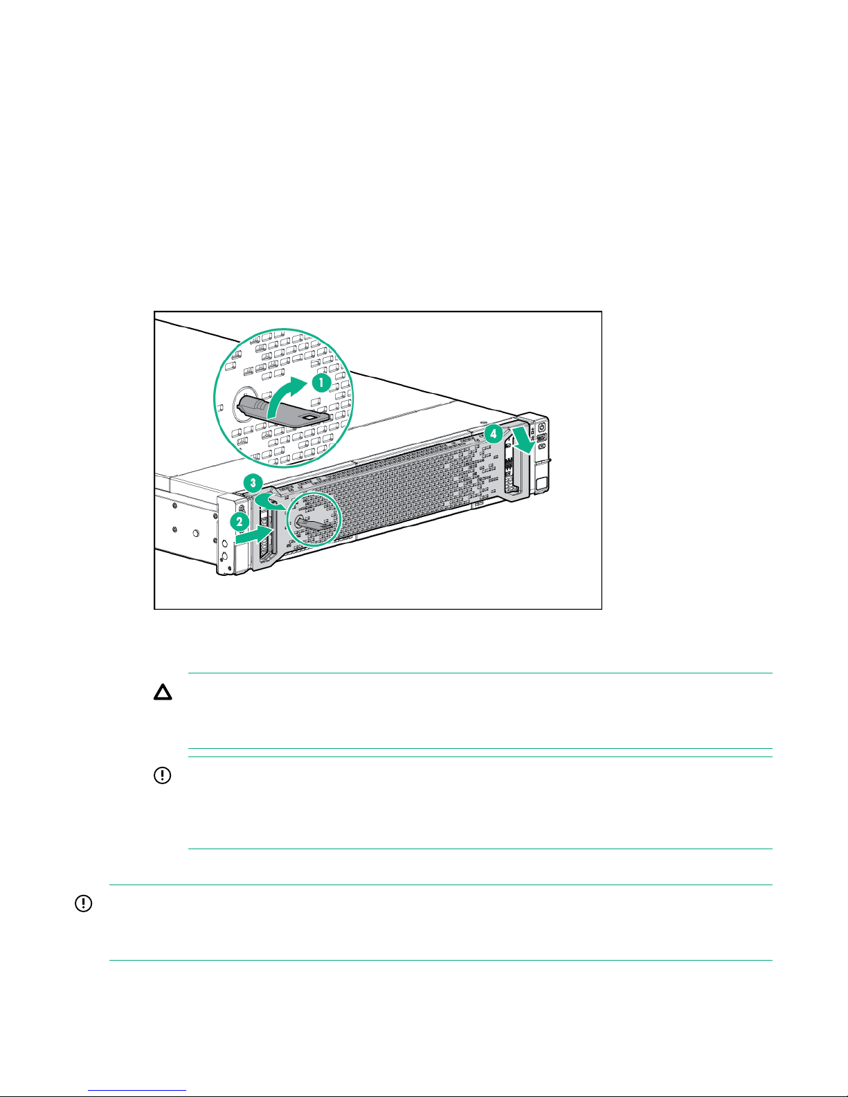
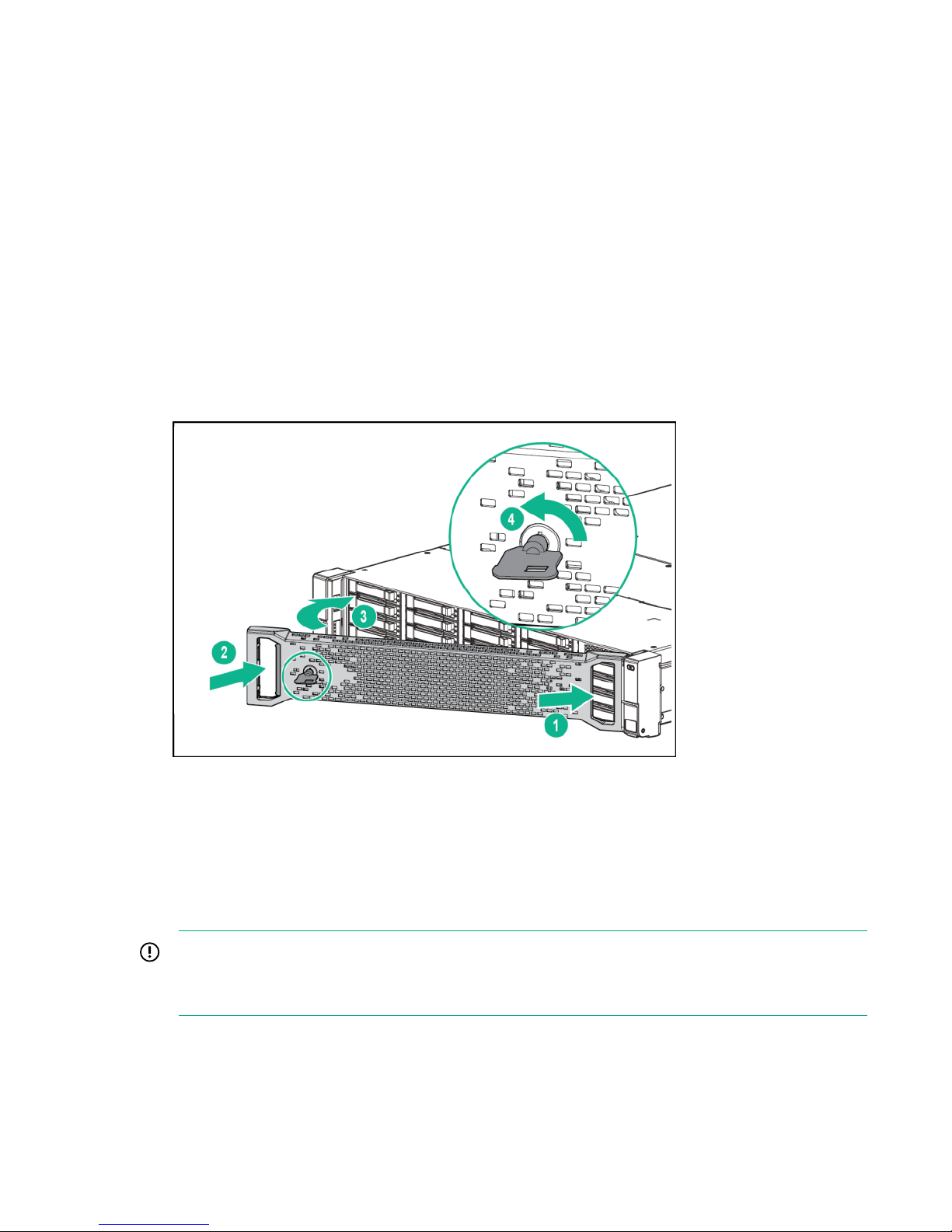
7. Remove the Bezel from the enclosure front.
a. Unlock the Bezel if necessary (1).
b. Press the release tab (2).
c. Rotate the Bezel away from the enclosure left side (3).
d. Pull the Bezel out from the enclosure right side (4).
Figure 1: Removing an HPE 3PAR StoreServ 7000 Storage Bezel
8. Locate the failed Drive by the LEDs.
CAUTION:
Before removing the Drive to avoid damaging the hardware or losing data, always confirm the
Drive by its solid amber Fault LED.
IMPORTANT:
If you do not see a solid amber Fault LED on the Drive, it could be the data has not been
vacated yet. When the Drive has failed and been spun down, the Fault LED becomes lit solid
amber and only then can you proceed with removal. This process may take several hours.
Removal:
IMPORTANT:
Do not remove the failed Drive until you have the replacement Drive ready. To prevent overheating, do not
leave the Drive Bay unpopulated for more than 10 minutes.
9. Remove the Drive.
Service of the hardware components 17
Page 18
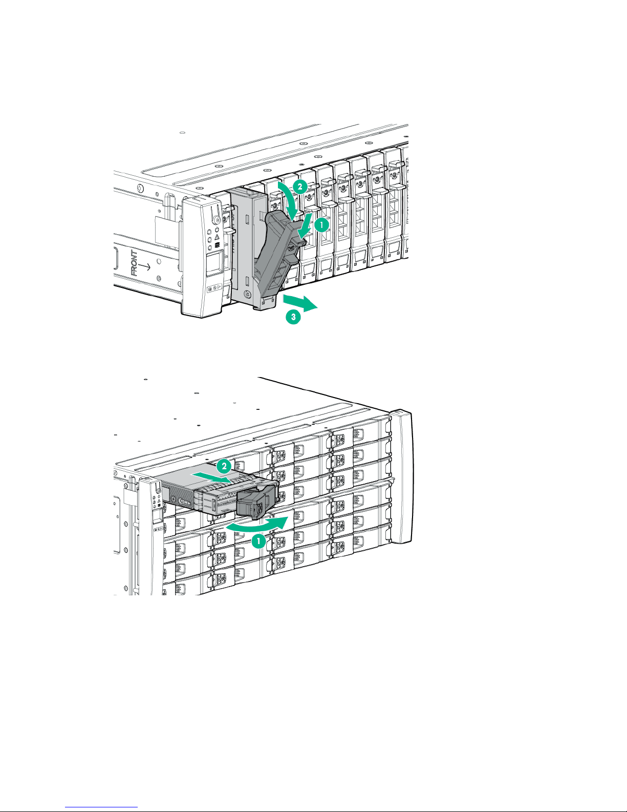
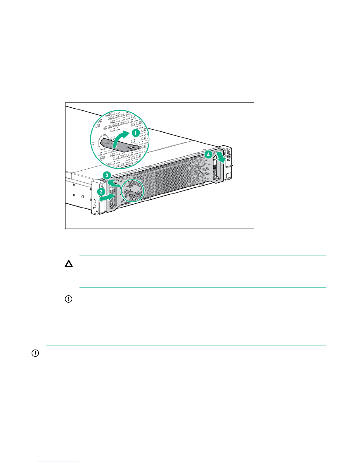
a. To release the handle into the open position, pinch the latch handle to release the handle into the
open position (1).
b. Extend the latch handle (2).
c. Slide the Drive out of the bay (3) and place on an ESD safe mat.
Figure 2: Removing an HPE 3PAR StoreServ 7000 Storage SFF Drive
Figure 3: Removing an HPE 3PAR StoreServ 7000 Storage LFF Drive
Replacement:
10. Install the Drive.
18 Service of the hardware components
Page 19

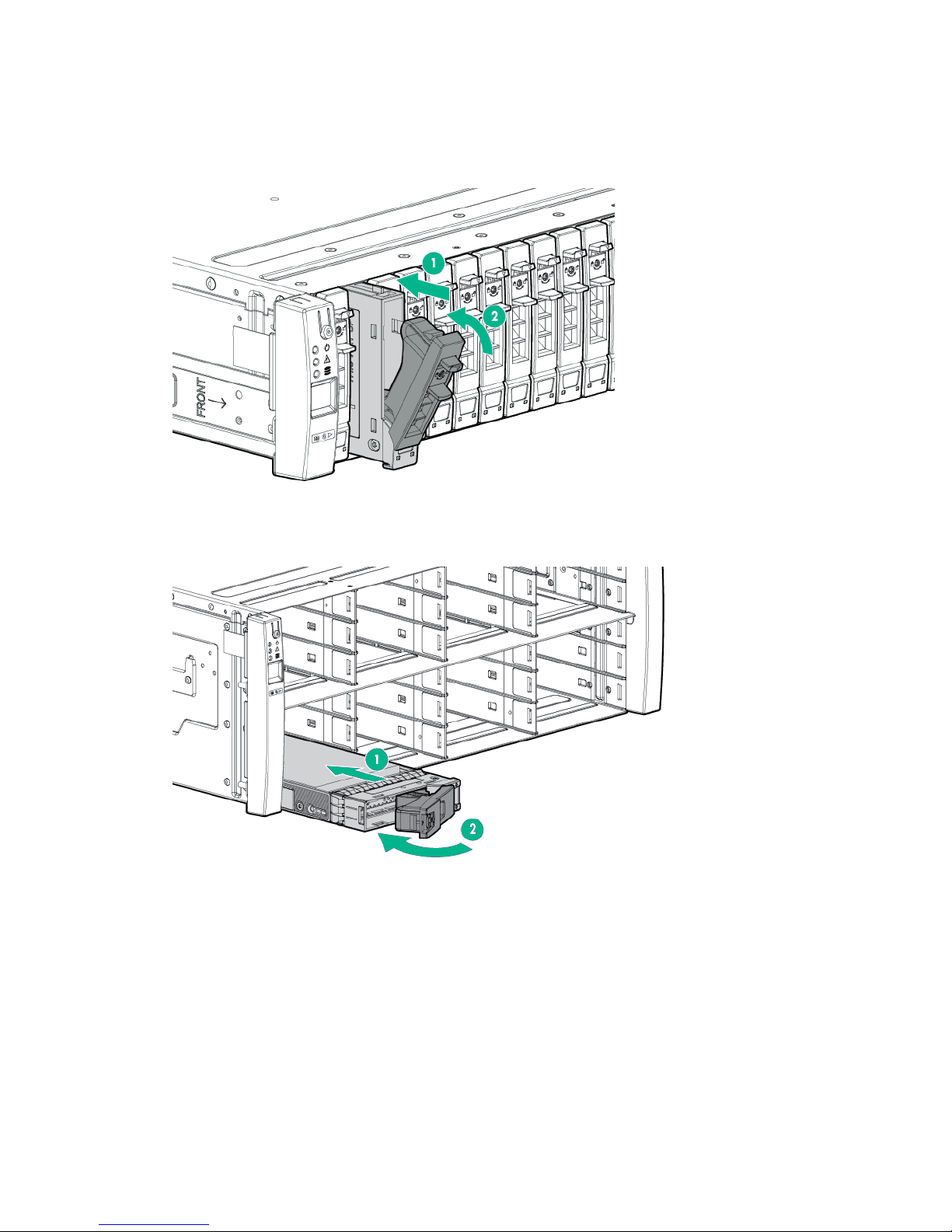
a. On the Drive, press the release button to open the handle.
b. With the latch handle of the Drive fully extended, align and slide the Drive into the bay until the
handle begins to engage (1).
c. To seat the Drive into the Drive bay, close the handle (2).
Verification:
11. Observe the newly installed Drive and confirm the Fault LED is off and the Status LED is solid green.
Figure 4: Installing an HPE 3PAR StoreServ 7000 Storage SFF Drive
Figure 5: Installing an HPE 3PAR StoreServ 7000 Storage LFF Drive
The change in the LEDs may take several minutes as the Drive is prepared for use by the system.
12. Verify the state of the replacement Drive.
From the SSMC interface, the Drive ID that you just replaced will be removed from the list, and the
replacement Drive will be assigned a new Drive ID and be in a healthy state.
Service of the hardware components 19
Page 20
13. From the HPE 3PAR SPOCC interface, verify that the State for the component and the storage
system are Normal (green).
14. After the component replacement, initiate Check Health of the storage system.
a. From the HPE 3PAR SPOCC interface main menu, click Support in the left navigation pane.
b. From the Service Processor - Support page, under StoreServs, click Health Check in the
Action column.
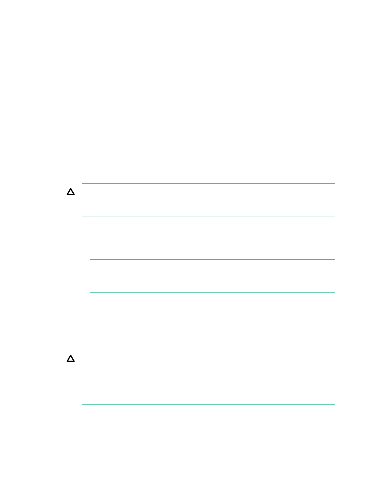
15. Install the Bezel on the enclosure front.
a. Insert the Bezel into the enclosure right side (1).
b. Press in the release tab (2).
c. Insert the Bezel into the enclosure left side (3).
d. Lock the Bezel (4) (optional).
Figure 6: Installing an HPE 3PAR StoreServ 7000 Storage Bezel
16. Follow the return instructions provided with the replacement component.
Replacing a Drive—SP 5.x
This procedure is for the replacement of an HPE 3PAR StoreServ 7000 Storage Drive using HPE 3PAR
Service Processor (SP) 5.x.
IMPORTANT:
When replacing a Drive that is Failed, Maintenance Mode is not required. By not setting
Maintenance Mode, alerts for other issues that might arise will continue to be sent to HPE.
20 Replacing a Drive—SP 5.x
Page 21
Procedure
Preparation:
1. Unpack the component and place on an ESD safe mat.
2. Connect to the HPE 3PAR Service Processor (SP)
3. Log in to the HPE 3PAR SP.
4. Initiate Check Health of the storage system.
Browse to the IP address:
https://<sp_ip_address>:8443
With the admin account credentials, the HPE 3PAR SP Service Console (SC) interface displays.
a. From the SC interface, select Systems.
b. Select Actions > Check health, and then select the Check health button. A scan of the storage
system will be run to make sure that there are no additional issues.
A scan of the storage system will be run to make sure that there are no additional issues.
CAUTION:
If health issues are identified during the Check Health scan, resolve these issues before
continuing. Refer to the details in the Check Health results and review the documentation.
5. Locate information about the failed Drive.
a. From the SC interface on the Systems page under the Health pane next to Details, click the link
labeled Failed to see the Overview page for the component. Notice the alert banner at the top of
the page that provides additional information.
NOTE:
On the Health pane of the Systems page, the State is Degraded and indicates the state of
the storage system and not the state of an individual component.
b. On the Physical Drives page under the Health pane, confirm that the Drive State shows Failed
and Vacated.
c. Click the View drop-down menu and select Schematic.
d. On the Schematic page, hover over the failed Drive and note the positioning information within
the storage system.
CAUTION:
If the Drive is still in a Degraded state instead of a Failed state, do not attempt to remove the
Drive from the enclosure, because the Drive is still vacating the data. If you remove a Drive in a
Degraded state, a loss of data may occur. Wait to remove the Drive once it enters a Failed
state, which indicates that the data has been vacated, and the Drive is safe to replace. This
process may take several hours.
6. Locate the Drive Enclosure (cage) that contains the failed Drive.
Service of the hardware components 21
Page 22
From the enclosure front, locate the enclosure that has a solid amber Drive Status LED on the left
Ear Cap (Bezel).
7. Remove the Bezel from the enclosure front.
a. Unlock the Bezel if necessary (1).
b. Press the release tab (2).
c. Rotate the Bezel away from the enclosure left side (3).
d. Pull the Bezel out from the enclosure right side (4).
Figure 7: Removing an HPE 3PAR StoreServ 7000 Storage Bezel
8. Locate the failed Drive by the LEDs.
CAUTION:
Before removing the Drive to avoid damaging the hardware or losing data, always confirm the
Drive by its solid amber Fault LED.
IMPORTANT:
If you do not see a solid amber Fault LED on the Drive, it could be the data has not been
vacated yet. When the Drive has failed and been spun down, the Fault LED becomes lit solid
amber and only then can you proceed with removal. This process may take several hours.
Removal:
IMPORTANT:
Do not remove the failed Drive until you have the replacement Drive ready. To prevent overheating, do not
leave the Drive Bay unpopulated for more than 10 minutes.
9. Remove the Drive.
22 Service of the hardware components
Page 23

a. To release the handle into the open position, pinch the latch handle to release the handle into the
open position (1).
b. Extend the latch handle (2).
c. Slide the Drive out of the bay (3) and place on an ESD safe mat.
Figure 8: Removing an HPE 3PAR StoreServ 7000 Storage SFF Drive
Figure 9: Removing an HPE 3PAR StoreServ 7000 Storage LFF Drive
Replacement:
10. Install the Drive.
Service of the hardware components 23
Page 24
a. On the Drive, press the release button to open the handle.
b. With the latch handle of the Drive fully extended, align and slide the Drive into the bay until the
handle begins to engage (1).
c. To seat the Drive into the Drive bay, close the handle (2).
Verification:
11. Observe the newly installed Drive and confirm the Fault LED is off and the Status LED is solid green.
Figure 10: Installing an HPE 3PAR StoreServ 7000 Storage SFF Drive
Figure 11: Installing an HPE 3PAR StoreServ 7000 Storage LFF Drive
The change in the LEDs may take several minutes as the Drive is prepared for use by the system.
12. Verify the state of the replacement Drive.
24 Service of the hardware components
Page 25

From the SC interface, the Drive ID that you just replaced will be removed from the list, and the
replacement Drive will be assigned a new Drive ID and be in a healthy state. The Schematic view
automatically refreshes.
13. From the SC interface, verify that the State of the component and the storage system are Normal
(green).
14. After the component replacement, initiate Check Health of the storage system.
a. From the SC interface, select Systems.
b. Select Actions > Check health. A scan of the storage system will be run to make sure that there
are no additional issues.
A scan of the storage system will be run to make sure that there are no additional issues.
15. Install the Bezel on the enclosure front.
a. Insert the Bezel into the enclosure right side (1).
b. Press in the release tab (2).
c. Insert the Bezel into the enclosure left side (3).
d. Lock the Bezel (4) (optional).
Figure 12: Installing an HPE 3PAR StoreServ 7000 Storage Bezel
16. Follow the return instructions provided with the replacement component.
SFP Transceiver Replacement—Mandatory CSR
component
An HPE 3PAR StoreServ 7000 Storage Small Form-Factor Pluggable (SFP) Transceiver is a mandatory
Customer Self Repair (CSR) component. An SFP Transceiver is installed in each onboard Fibre Channel
(FC) port and in the ports of Host Adapters.
SFP Transceiver Replacement—Mandatory CSR component 25
Page 26
WARNING:
When the storage system is on, do not stare at the FC fibers, because doing so could damage your
eyes.
CAUTION:
To prevent damage when handling the SFP Transceiver, do not touch the gold contact leads.
IMPORTANT:
All SFP ports must contain an SFP Transceiver and cable or a dust cover.
Procedure
• Based on your HPE 3PAR Service Processor (SP) software version, select and complete a
replacement procedure:
◦ Replacing an SFP Transceiver—SP 4.x on page 26
◦ Replacing an SFP Transceiver—SP 5.x on page 28
Replacing an SFP Transceiver—SP 4.x
This procedure is for the replacement of an HPE 3PAR StoreServ 7000 Storage Small Form-Factor
Pluggable (SFP) Transceiver using HPE 3PAR Service Processor (SP) 4.x.
Procedure
Preparation:
1. Unpack the component and place on an ESD safe mat.
2. Connect to the HPE 3PAR Service Processor (SP).
3. Log in to the HPE 3PAR SP.
4. Initiate a maintenance window that stops the flow of system alerts from being sent to HPE by setting
Browse to either the IP address or hostname: https://<sp_ip_address> or https://
<hostname> .
With the 3parcust account credentials, the HPE 3PAR Service Processor Onsite Customer Care
(SPOCC) interface displays.
Maintenance Mode.
a. From the HPE 3PAR SPOCC interface main menu, select SPMAINT in the left navigation pane.
b. From the HPE 3PAR SPMaint interface main menu under Service Processor - SP Maintenance,
select StoreServ Configuration Management.
c. Under Service Processor - StoreServ Configuration, select Modify under Action.
d. Under Service Processor - StoreServ Info, select On for the Maintenance Mode setting.
5. Initiate Check Health of the storage system.
26 Replacing an SFP Transceiver—SP 4.x
Page 27

a. From the HPE 3PAR SPOCC interface main menu, click Support in the left navigation pane.
b. From the Service Processor - Support page, under StoreServs, click Health Check in the
Action column.
A pop-up window appears showing a status message while the health check runs.
NOTE:
When running the Health Check using Internet Explorer, the screen might remain blank
while information is gathered. This process could take a few minutes before displaying
results. Wait for the process to complete and do not attempt to cancel or close the browser.
When the health check process completes, it creates a report and displays in a new browser
window.
c. To review the report, click either Details or View Summary.
CAUTION:
If health issues are identified during the Check Health scan, resolve these issues before
continuing. Refer to the details in the Check Health results and contact HPE support if
necessary.
6. Review the information in the email alert notification.
If the email notifications are enabled, information about the failed port due to the failed SFP
Transceiver is provided in an email alert notification. The port position in the storage system is
provided as Node:Slot:Port (N:S:P).
7. Review the information in the HPE 3PAR StoreServ Management Console (SSMC) interface alert
8. Locate the failed SFP Transceiver.
Removal:
9. Label the optical cable connected to the failed SFP Transceiver with the port location, and then
10. Remove the SFP Transceiver.
notification.
On the Ports screen, an alert notification banner appears that contains the information for the failed
port due to the failed SFP Transceiver. From the SSMC main menu, select Storage Systems >
Systems, select the storage system from the list, select Configuration view from the detail pane,
click the total ports hyperlink from the Ports panel. In the alert notification banner, the port position is
provided as Node:Slot:Port (N:S:P).
NOTE:
The health and details listed in the SSMC for the failed port might still show as healthy. If this
occurs, rely on the information in the alert notification about the failed port and confirm that you
have located the failed port by its LEDs that will have the Port Speed LED off and the Link
Status LED flashing green.
To locate the port containing the failed SFP Transceiver, use the Node:Slot:Port position. The port
will have a flashing green Link Status LED and the Port Speed LED will be off.
disconnect the cable.
Service of the hardware components 27
Page 28

a. Open the retaining clip on the SFP Transceiver.
b. Slide the SFP Transceiver out of the port slot.
Replacement:
11. Install the SFP Transceiver.
a. Open the retaining clip on the SFP Transceiver.
b. Slide the SFP Transceiver into the port slot on the controller node until fully seated.
c. Close the retaining clip.
12. Reconnect the optical cable in the same location recorded on the label.
Verification:
13. Verify that the replacement SFP Transceiver has been successfully installed.
On the port with the replacement SFP Transceiver, verify that the Link Status LED is solid green and
the Port Speed LED is flashing amber.
IMPORTANT:
If an optical cable will not be connected to the SFP Transceiver, install a dust cover.
14. From the HPE 3PAR SPOCC interface, verify that the State for the component and the storage
system are Normal (green).
15. After the component replacement, initiate Check Health of the storage system.
a. From the HPE 3PAR SPOCC interface main menu, click Support in the left navigation pane.
b. From the Service Processor - Support page, under StoreServs, click Health Check in the
Action column.
16. If significant time is left in the maintenance window, end the Maintenance Mode.
a. From the HPE 3PAR SPOCC interface main menu, select SPMAINT in the left navigation pane.
b. From the HPE 3PAR SPMAINT interface main menu under Service Processor - SP
Maintenance, select StoreServ Configuration Management.
c. Under Service Processor - StoreServ Configuration, select Modify under Action.
d. Under Service Processor - StoreServ Info, select Off for the Maintenance Mode setting.
17. Follow the return instructions provided with the replacement component.
Replacing an SFP Transceiver—SP 5.x
This procedure is for the replacement of an HPE 3PAR StoreServ 7000 Storage Small Form-Factor
Pluggable (SFP) Transceiver using HPE 3PAR Service Processor (SP) 5.x.
28 Replacing an SFP Transceiver—SP 5.x
Page 29
Procedure
Preparation:
1. Unpack the component and place on an ESD safe mat.
2. Connect to the HPE 3PAR Service Processor (SP)
3. Log in to the HPE 3PAR SP.
4. Initiate a maintenance window that stops the flow of system alerts from being sent to HPE by setting
Browse to the IP address:
https://<sp_ip_address>:8443
With the admin account credentials, the HPE 3PAR SP Service Console (SC) interface displays.
Maintenance Mode.
a. From the SC interface, select Systems.
b. Select Actions > Set maintenance mode, and then follow the instructions in the dialog that
opens.
TIP:
When putting the storage system in maintenance mode or editing the maintenance mode,
you need to specify the duration in hours and a description of the reason for the
maintenance window.
To edit the maintenance window, select Actions > Set maintenance mode, and then click
the Edit icon next to the maintenance window.
5. Initiate Check Health of the storage system.
a. From the SC interface, select Systems.
b. Select Actions > Check health, and then select the Check health button. A scan of the storage
system will be run to make sure that there are no additional issues.
A scan of the storage system will be run to make sure that there are no additional issues.
CAUTION:
If health issues are identified during the Check Health scan, resolve these issues before
continuing. Refer to the details in the Check Health results and review the documentation.
6. Review the information in the email alert notification.
If the email notifications are enabled, information about the failed port due to the failed SFP
Transceiver is provided in an email alert notification. The port position in the storage system is
provided as Node:Slot:Port (N:S:P).
7. Review the information in the HPE 3PAR Service Console (SC) alert notification.
An alert notification banner appears that contains the information for the failed port due to the failed
SFP. In the alert notification banner, the port position is provided as Node:Slot:Port (N:S:P). To
expand the box, click the banner, which shows additional information about the nature of the alert.
Click the details link to be taken to the Activity view for the appropriate component. You can also
view a graphical representation of the components from the Schematic view.
Service of the hardware components 29
Page 30

8. Locate the failed SFP Transceiver.
To locate the port containing the failed SFP Transceiver, use the Node:Slot:Port position. The port
will have a flashing green Link Status LED and the Port Speed LED will be off.
Removal:
9. Label the optical cable connected to the failed SFP Transceiver with the port location, and then
disconnect the cable.
10. Remove the SFP Transceiver.
a. Open the retaining clip on the SFP Transceiver.
b. Slide the SFP Transceiver out of the port slot.
Replacement:
11. Install the SFP Transceiver.
a. Open the retaining clip on the SFP Transceiver.
b. Slide the SFP Transceiver into the port slot on the controller node until fully seated.
c. Close the retaining clip.
12. Reconnect the optical cable in the same location recorded on the label.
Verification:
13. Verify that the replacement SFP Transceiver has been successfully installed.
14. From the SC interface, verify that the State of the component and the storage system are Normal
15. After the component replacement, initiate Check Health of the storage system.
16. If significant time is left in the maintenance window, end the Maintenance Mode.
IMPORTANT:
If an optical cable will not be connected to the SFP Transceiver, install a dust cover.
On the port with the replacement SFP Transceiver, verify that the Link Status LED is solid green and
the Port Speed LED is flashing amber.
(green).
a. From the SC interface, select Systems.
b. Select Actions > Check health. A scan of the storage system will be run to make sure that there
are no additional issues.
A scan of the storage system will be run to make sure that there are no additional issues.
a. From the SC interface, select Systems.
b. Select Actions > Set maintenance mode.
c. To end the maintenance window associated with the replacement, click X. The flow of support
information and local notifications of system alerts are again sent to HPE.
17. Follow the return instructions provided with the replacement component.
30 Service of the hardware components
Page 31

Upgrade of the storage system
IMPORTANT:
Some Hewlett Packard Enterprise components are not designed for a Customer Self Upgrade
(CSU). To satisfy the customer warranty, Hewlett Packard Enterprise requires that an authorized
service provider replace such components.
HPE 3PAR StoreServ 7000 Storage products include HPE 3PAR licensing which enables all functionality
associated with the system. A failure to register the license key might limit access and restrict upgrading
of your storage system. Before you proceed with upgrading, verify all applicable licenses associated with
the storage system are registered.
Drives upgrade—Mandatory CSU component
The upgrade of a system by adding additional HPE 3PAR StoreServ 7000 Storage Drives is a mandatory
Customer Self Upgrade (CSU) component.
CAUTION:
• To ensure proper thermal control, slot-filler Blanks are provided with the enclosures and must be
inserted in all unused Drive Bays in the enclosure. Operate the enclosure only when all Drive
Bays are populated with either a Drive or a Blank.
• If the storage system is enabled with the Data-at-Rest (DAR) encryption feature, only use
Federal Information Processing Standard (FIPS) capable encrypted Drives.
• Before installing Drives into enclosures, make sure that the enclosures are free of obstructions
(such as loose screws, hardware, or debris). Inspect the Drives before installing them in the
enclosure to make sure that they are not damaged.
• To avoid errors when powering on the storage system, all enclosures must have at least one
Drive Pair installed by following the allocating and loading guidelines provided in this document.
IMPORTANT:
The guidelines for how the Drives are installed, allocated, and balanced are critical to the
performance and reliability of your storage system.
Prerequisites
Determine an installation plan for allocating and loading the Drives based on the provided guidelines,
number of Drives, and Drive types to install.
Procedure
1. Review Guidelines for allocating and loading Drives on page 32.
2. Review Guidelines for adding more Drives to the storage system on page 35.
3. Based on your HPE 3PAR Service Processor (SP) software version, select and complete a procedure:
Upgrade of the storage system 31
Page 32

• Upgrading to add Drives—SP 4.x on page 35
• Upgrading to add Drives—SP 5.x on page 39
Guidelines for allocating and loading Drives
• A Drive Pair or Drive Pairs must be installed together and must be of the same capacity, speed, and
type. Never install an uneven number of Drives of one type within a single enclosure.
• While making sure to load Drives in pairs of the same Drive type, try to distribute the same number of
Drives and Drive types in all enclosures. An even distribution may not always be possible.
• Different Drive types can be loaded next to each other in the same enclosure, but load all the Drives of
one Drive type before loading Drives of a different Drive type.
HPE 3PAR StoreServ 7000 Storage SFF Drive loading guidelines and examples
SFF Drives are loaded starting at bay 0, left to right. The bays are numbered 0 through 23.
Figure 13: HPE 3PAR StoreServ 7000 Storage SFF numbering of Drive bays
Figure 14: HPE 3PAR StoreServ 7000 Storage SFF Drive loading order
Example of a correct Drive allocation in one SFF enclosure
This example demonstrates an SFF enclosure loaded correctly with these Drives: two pairs of FC, three
pairs of NL, and two pairs of SSD.
32 Guidelines for allocating and loading Drives
Page 33

Example of a correct Drive allocation in two SFF enclosures
This example demonstrates two SFF enclosures loaded correctly with these Drives: three pairs of FC
(six Drives), five pairs of NL (10 Drives), and two pairs of SSD (four Drives).
Example of an unbalanced allocation in two SFF enclosures
CAUTION:
This example demonstrates an unbalanced allocation due to the NL Drives not being installed in
even pairs.
Avoid having an odd number of Drives allocated in the Drive enclosures.
HPE 3PAR StoreServ 7000 Storage LFF Drive loading guidelines and examples
IMPORTANT:
Notice that the numbering for the order and direction that Drives are installed in the LFF enclosure
do not follow the same number order used to identify Drives from the storage system management
software. Drives are installed in vertical columns instead of by sequential numbering.
LFF Drives are loaded starting at bay 0, bottom to top in the left-most column, then bottom to top in the
next column, and so on. Note bay numbering does not follow how the bays are loaded. The bays are
Upgrade of the storage system 33
Page 34

numbered left to right, and then the next row up, left to right, and so on, from 0 to 23. The first four LFF
Drives are loaded into bays 0, 4, 8, and 12.
Figure 15: HPE 3PAR StoreServ 7000 Storage LFF numbering of Drive bays
Figure 16: HPE 3PAR StoreServ 7000 Storage LFF Drive loading order
Example of a correct Drive allocation in one LFF enclosure
This example demonstrates an LFF enclosure loaded correctly with these Drives: three pairs of NL (six
Drives) and one pair of SSD (two Drives).
34 Upgrade of the storage system
Page 35

Example of an unbalanced allocation in one LFF enclosure
CAUTION:
This example demonstrates an unbalanced allocation due to the NL Drives being installed across
all four columns.
Instead, the correct way to load the Drives is loading in the first column before moving to the next
column to the right.
Guidelines for adding more Drives to the storage system
When adding more HPE 3PAR StoreServ 7000 Storage Drives to the storage system, previously installed
Drives do not need to be removed for the sake of keeping Drives of the same type together. Additional
Drives should be installed in the next available slots, following the rules for allocation and balancing
between enclosures.
• The first expansion Drive Enclosure added to a system must be populated with the same number of
Drives as the Controller Node Enclosure.
• Upgrades can be only SFF Drives, only LFF Drives, or a mixture of SFF and LFF Drives.
• For an upgrade of only SFF Drives, install the Drives by splitting the Drives evenly across all of the
SFF Drive Enclosures.
• For an upgrade of only LFF Drives, install the Drives by splitting the Drives evenly across all of the
LFF Drive Enclosures.
• For an upgrade with a mix of SFF and LFF Drives, install the Drives in pairs (Drive Pair) of the same
type by splitting the SFF Drives across all of the SFF Drive Enclosures and the LFF Drives across all
of the LFF Drive Enclosures with as much of an equal distribution as possible between the enclosures.
If an equal distribution is not possible, you should get as close as possible without breaking the rules.
Upgrading to add Drives—SP 4.x
This procedure is for the upgrade of installing HPE 3PAR StoreServ 7000 Storage Drives using HPE
3PAR Service Processor (SP) 4.x.
Guidelines for adding more Drives to the storage system 35
Page 36

Procedure
Preparation:
1. Unpack the component and place on an ESD safe mat.
2. Connect to the HPE 3PAR Service Processor (SP).
3. Log in to the HPE 3PAR SP.
4. Initiate Check Health of the storage system.
Browse to either the IP address or hostname: https://<sp_ip_address> or https://
<hostname> .
With the 3parcust account credentials, the HPE 3PAR Service Processor Onsite Customer Care
(SPOCC) interface displays.
a. From the HPE 3PAR SPOCC interface main menu, click Support in the left navigation pane.
b. From the Service Processor - Support page, under StoreServs, click Health Check in the
Action column.
A pop-up window appears showing a status message while the health check runs.
NOTE:
When running the Health Check using Internet Explorer, the screen might remain blank
while information is gathered. This process could take a few minutes before displaying
results. Wait for the process to complete and do not attempt to cancel or close the browser.
When the health check process completes, it creates a report and displays in a new browser
window.
c. To review the report, click either Details or View Summary.
CAUTION:
If health issues are identified during the Check Health scan, resolve these issues before
continuing. Refer to the details in the Check Health results and contact HPE support if
necessary.
5. Obtain the current Drive count.
From the SSMC interface, select Storage Systems > Drive Enclosures > Physical Drives.
6. Remove the Bezel from the enclosure front.
a. Unlock the Bezel if necessary (1).
b. Press the release tab (2).
c. Rotate the Bezel away from the enclosure left side (3).
d. Pull the Bezel out from the enclosure right side (4).
36 Upgrade of the storage system
Page 37

Installation:
7. Remove the slot-filler Blanks from where you will be installing the Drive pairs.
8. Install the Drive.
Figure 17: Removing an HPE 3PAR StoreServ 7000 Storage Bezel
a. On the Drive, press the release button to open the handle.
b. With the latch handle of the Drive fully extended, align and slide the Drive into the bay until the
handle begins to engage (1).
c. To seat the Drive into the Drive bay, close the handle (2).
Figure 18: Installing an HPE 3PAR StoreServ 7000 Storage SFF Drive
Upgrade of the storage system 37
Page 38

9. Repeat the steps for each Drive.
Verification:
10. Verify that the Drives have been admitted and integrated into the storage system.
11. After the component replacement, initiate Check Health of the storage system.
Figure 19: Installing an HPE 3PAR StoreServ 7000 Storage LFF Drive
IMPORTANT:
For proper airflow and cooling, a slot-filler Blank must remain installed in all unused Drive bays.
Confirm on the drives that the Status LED is solid green.
Within six minutes (depending on the storage system load and the size of the upgrade), the Drives
will be admitted, integrated, assigned an ID number, and the storage system starts to initialize the
chunklets to ready for use. Chunklet initialization can take several hours to complete and the output
of the available capacity is displayed.
a. From the HPE 3PAR SPOCC interface main menu, click Support in the left navigation pane.
b. From the Service Processor - Support page, under StoreServs, click Health Check in the
Action column.
12. Install the Bezel on the enclosure front.
a. Insert the Bezel into the enclosure right side (1).
b. Press in the release tab (2).
c. Insert the Bezel into the enclosure left side (3).
d. Lock the Bezel (4) (optional).
38 Upgrade of the storage system
Page 39

Figure 20: Installing an HPE 3PAR StoreServ 7000 Storage Bezel
13. Follow the return instructions provided with the replacement component.
Upgrading to add Drives—SP 5.x
This procedure is for the upgrade of installing HPE 3PAR StoreServ 7000 Storage Drives using HPE
3PAR Service Processor (SP) 5.x.
Procedure
Preparation:
1. Unpack the component and place on an ESD safe mat.
2. Connect to the HPE 3PAR Service Processor (SP)
Browse to the IP address:
https://<sp_ip_address>:8443
3. Log in to the HPE 3PAR SP.
With the admin account credentials, the HPE 3PAR SP Service Console (SC) interface displays.
4. Initiate a maintenance window that stops the flow of system alerts from being sent to HPE by setting
Maintenance Mode.
a. From the SC interface, select Systems.
b. Select Actions > Set maintenance mode, and then follow the instructions in the dialog that
opens.
Upgrading to add Drives—SP 5.x 39
Page 40

TIP:
When putting the storage system in maintenance mode or editing the maintenance mode,
you need to specify the duration in hours and a description of the reason for the
maintenance window.
To edit the maintenance window, select Actions > Set maintenance mode, and then click
the Edit icon next to the maintenance window.
5. Initiate Check Health of the storage system.
a. From the SC interface, select Systems.
b. Select Actions > Check health, and then select the Check health button. A scan of the storage
system will be run to make sure that there are no additional issues.
A scan of the storage system will be run to make sure that there are no additional issues.
CAUTION:
If health issues are identified during the Check Health scan, resolve these issues before
continuing. Refer to the details in the Check Health results and review the documentation.
6. Obtain the current Drive count.
From the SC interface, select Storage Systems > Physical Drives. At the top, you can see the total
number of drives. Scroll down to the bottom of the list to see all the drives installed in your system.
To see a graphical representation of the current drives, select Storage Systems > Drive Enclosure,
and then select Schematic from the View drop-down menu.
7. Remove the Bezel from the enclosure front.
a. Unlock the Bezel if necessary (1).
b. Press the release tab (2).
c. Rotate the Bezel away from the enclosure left side (3).
d. Pull the Bezel out from the enclosure right side (4).
40 Upgrade of the storage system
Page 41

Installation:
8. Remove the slot-filler Blanks from where you will be installing the Drive pairs.
9. Install the Drive.
Figure 21: Removing an HPE 3PAR StoreServ 7000 Storage Bezel
a. On the Drive, press the release button to open the handle.
b. With the latch handle of the Drive fully extended, align and slide the Drive into the bay until the
handle begins to engage (1).
c. To seat the Drive into the Drive bay, close the handle (2).
Figure 22: Installing an HPE 3PAR StoreServ 7000 Storage SFF Drive
Upgrade of the storage system 41
Page 42

10. Repeat the steps for each Drive.
Verification:
11. From the SC interface, verify the installation of the additional Drives. The display refreshes
Figure 23: Installing an HPE 3PAR StoreServ 7000 Storage LFF Drive
IMPORTANT:
For proper airflow and cooling, a slot-filler Blank must remain installed in all unused Drive bays.
periodically, and you should see the newly inserted Drives, which are automatically admitted into the
storage system.
IMPORTANT:
The storage system can be used normally, but newly added Drive capacity must be initialized
before it can be allocated.
Within six minutes (depending on the storage system load and the size of the upgrade), the Drives
will be assigned an ID number, and the storage system starts to initialize the chunklets to ready for
use. Chunklet initialization can take several hours to complete and the output of the available
capacity is displayed. Once the Drives are admitted, notice at the top of the list that your Drive count
has increased appropriately. Scroll down to the bottom of the list to see all the Drives installed in your
system.
12. Initiate Check Health of the storage system.
a. From the SC interface, select Systems.
b. Select Actions > Check health, and then select the Check health button. A scan of the storage
system will be run to make sure that there are no additional issues.
A scan of the storage system will be run to make sure that there are no additional issues.
CAUTION:
If health issues are identified during the Check Health scan, resolve these issues before
continuing. Refer to the details in the Check Health results and review the documentation.
42 Upgrade of the storage system
Page 43

13. Install the Bezel on the enclosure front.
a. Insert the Bezel into the enclosure right side (1).
b. Press in the release tab (2).
c. Insert the Bezel into the enclosure left side (3).
d. Lock the Bezel (4) (optional).
Figure 24: Installing an HPE 3PAR StoreServ 7000 Storage Bezel
14. Follow the return instructions provided with the replacement component.
Upgrade of the storage system 43
Page 44

More information for service and upgrade of
the storage system
Accounts and credentials for service and upgrade
IMPORTANT:
There are separate accounts for access to the storage system or the service processor. The
account options and type of password vary based on the version of the software installed for the
storage system and the version of the software installed on the service processor.
• Beginning with HPE 3PAR SP 5.x for the service processor, time-based or encryption-based
passwords are implemented for the support accounts used with the SP.
• Beginning with HPE 3PAR OS 3.2.2 for the storage system, time-based or encryption-based
passwords are implemented for the support accounts used with the storage system.
Time-based password (strong password)
With the time-based password option, the Hewlett Packard Enterprise Support person or authorized
service provider can acquire the account password when needed without the involvement of the
administrator. The time-based password is generated using strong cryptographic algorithms and large key
sizes, is valid for 60 minutes, and is automatically regenerated at the start of each hour.
During the service, upgrade, or diagnostic procedure, the account password remains active until logging
out of the account, even if 60 minutes is exceeded. During the procedure, if it is necessary to log out of
the account and then log back in to the account (for example, closing the session or rebooting a
Controller Node), do either of the following:
• Within the same hour, use the same password.
• If a new hour has started, obtain a newly generated password.
Encryption-based password (strong password)
With the encryption-based (ciphertext) password option, the administrator initiates the generation or
regeneration of account ciphertext that is copied and provided to the authorized service provider. The
authorized service provider decrypts the ciphertext to obtain the account password that they will use for
the service, upgrade, or diagnostic procedure. The password does not expire. After the service, upgrade,
or diagnostic procedure is completed, the administrator may regenerate a new ciphertext to make the
current password invalid. Only the administrator initiates the generation or regeneration of the account
ciphertext for a new password.
HPE 3PAR Service Processor accounts for service and upgrade
For access to the HPE 3PAR Service Processor (SP) interfaces, there are the following account options
for the administrator or for Hewlett Packard Enterprise Support personnel and authorized service
providers. Based on the account, there are differences in the access it provides to the HPE 3PAR SP
interfaces, the type of password options, and the permissions associated with the account.
44 More information for service and upgrade of the storage system
Page 45

Interfaces for HPE 3PAR SP 5.x:
• HPE 3PAR Service Console (SC)
• HPE 3PAR Text-based User Interface (TUI)
Interfaces for HPE 3PAR SP 4.x:
• HPE 3PAR Service Processor Onsite Customer Care (SPOCC)
• HPE 3PAR SPMaint utility (SPMaint)
• HPE 3PAR CPMaint utility (CPMaint)
Accounts with HPE 3PAR SP 5.x for service and upgrade
Account Password options Interface access Permissions
admin Static password
Administrator sets/changes
hpepartner Static password
Administrator sets/changes
• SC through a web browser
• TUI through a physical or
virtual console
• TUI through SSH
• SC through a web browser
• TUI through a physical or
virtual console
• TUI through SSH
• Only the administrator
• Default account
• Can create new local SP
users
• Only authorized service
providers
• Service and diagnostic
functions
Table Continued
More information for service and upgrade of the storage system 45
Page 46

Accounts with HPE 3PAR SP 5.x for service and upgrade
Account Password options Interface access Permissions
hpesupport Time-based or encryption-
based password
• Administrator sets the
password option
through the SC or TUI
• For encryption-based
password, administrator
regenerates ciphertext
(blob) through the SC
or TUI
• Authorized service
provider obtains the
ciphertext (blob) from
the administrator and
retrieves the password
through the StoreFront
Remote
root Time-based or encryption-
based password
• Administrator sets the
password option
through the SC or TUI
• SC through a web browser
• TUI and Linux Shell through
a physical or virtual console
• Only HPE Support
• Service and diagnostic
functions
• TUI and Linux Shell through
SSH
SP Linux shell • Only HPE Support and
authorized service
providers
• Service and diagnostic
functions
• For encryption-based
password, administrator
regenerates ciphertext
(blob) through the SC
or TUI
• Authorized service
provider obtains the
ciphertext (blob) from
the administrator and
retrieves the password
through the StoreFront
Remote
46 More information for service and upgrade of the storage system
Page 47

Accounts with HPE 3PAR SP 4.0 for service and upgrade
Account Password options Interface access Permissions
3parcust Static password
Administrator sets/changes
cpmaint Static password
Administrator sets/changes
spvar Static password
Administrator sets/changes
spdood Static password
HPE sets/changes per
release
• SPOCC through a web
browser
• SPMaint through a physical
or virtual console
• SPMaint through SSH
• SP Linux shell
• CPMaint
• SPOCC through a web
browser
• SPMaint through a physical
or virtual console
• SPMaint through SSH
• SPOCC through a web
browser
• SPMaint through a physical
or virtual console
• Only the administrator
• Default account
• Can create new local SP
users
• Only the administrator
• Administrative Secure
Service Agent (SSA)
functions
• Only HPE personnel and
authorized service
providers
• Service and diagnostic
functions
• Only HPE Support
• Service and diagnostic
functions
• SPMaint through SSH
root Static password
HPE sets/changes per
release
SP Linux shell • Only HPE Support and
authorized service
providers
• Service and diagnostic
functions
Setting time-based or encryption-based password option from the SP 5.x SC
Procedure
1. Connect and log in to the HPE 3PAR Service Processor (SP) 5.x.
2. From the HPE 3PAR Service Console (SC) main menu, select Service Processor, and then select
Actions > HPE Support password
Setting time-based or encryption-based password option from the SP 5.x SC 47
Page 48

3. Select Time based password or Encryption based password.
4. Click Apply.
Generating the encryption-based ciphertext from the SP 5.x SC
In advance or at the time of a support session, the administrator can generate the ciphertext (blob) and
provide it to Hewlett Packard Enterprise Support to be deciphered. Before or upon arriving at the site, the
approved service provider can obtain the password from Hewlett Packard Enterprise Support over the
phone, text message, or email.
Procedure
1. Connect and log in to the HPE 3PAR Service Processor (SP) 5.x.
2. From the HPE 3PAR Service Console (SC) main menu, select Service Processor, and then select
Actions > HPE Support password.
3. Select Encryption based password.
4. Click Apply.
The ciphertext is displayed.
5. Copy and paste that ciphertext into an email, text message, or into an encrypted zip file and send to
Hewlett Packard Enterprise Support.
The ciphertext is safe to email, because the random credential contained in the ciphertext is first
encrypted and then wrapped using a public key. Only Hewlett Packard Enterprise can unwrap the
encrypted credential using the corresponding private key.
Setting time-based or encryption-based password option from the SP 5.x TUI
Procedure
1. Connect and log in to the HPE 3PAR Service Processor (SP) 5.x.
2. From the HPE 3PAR Text-Based User Interface (TUI) main menu, enter the menu option for Secure
Password Management.
The current mode is displayed after Current password mode: as either TIME or ENCRYPT.
3. Enter the menu option for Change password mode to <TIME or ENCRYPT>.
48 Generating the encryption-based ciphertext from the SP 5.x SC
Page 49

Generating the encryption-based ciphertext from the SP 5.x TUI
Procedure
1. Connect and log in to the HPE 3PAR Service Processor (SP) 5.x.
2. From the HPE 3PAR Text-Based User Interface (TUI) main menu, enter 5 for 5 == Secure Password
Management.
The current mode is
displayed as:
Current password mode:
ENCRYPT
3. Enter either 2 for 2 == Display password blob for root or enter 3 for 3 == Display password blob
for hpesupport.
The ciphertext (blob) is displayed.
4. Copy the entire ciphertext and paste it into an email to Hewlett Packard Enterprise Support or to the
approved service provider. The ciphertext is safe to email, because the random credential contained in
the ciphertext is first encrypted and then wrapped using a public key. Only Hewlett Packard Enterprise
can unwrap the encrypted credential using the corresponding private key.
When copying the ciphertext,
copy the text starting with:
- - - Begin tpd blob
- - -
and all the text ending with:
- - - End tpd blob -
- -
Storage system accounts for service and upgrade
For access to the HPE 3PAR StoreServ Storage system interfaces, there are the following account
options for the administrator or for HPE Support personnel and authorized service providers. Based on
the account, there are differences in the access it provides to the storage system interfaces, the type of
password options, and the permissions associated with the account.
Generating the encryption-based ciphertext from the SP 5.x TUI 49
Page 50

Storage system accounts with HPE 3PAR OS 3.3.1 and 3.2.2 for service and upgrade
Account PW options Interface access Permissions
3paradm Static password
Administrator sets/changes
through the Administrator
console
console Time-based or encrypted-
based password
• Administrator sets the
password option through
CLI commands
• For encrypted-based
password, administrator
retrieves/exports the
ciphertext (blob) through
CLI commands
root Time-based or encrypted-
based password
• Main console
• Administrator console
• Interactive CLI
• Main console
• Administrator console
Linux Shell on the storage
system
• Only the administrator
• Create new CLI user
accounts
• Service and diagnostic
functions
• Super rights
• Only HPE Support and
authorized service providers
• Service and diagnostic
functions
• Only HPE Support and
authorized service providers
• Administrator sets the
password option through
CLI commands
• For encrypted-based
password, administrator
retrieves/exports the
ciphertext (blob) through
CLI commands
• Service and diagnostic
functions
Setting time-based or encryption-based password option for a storage system account
Procedure
1. Connect and log in to the HPE 3PAR Service Processor (SP) and access the interactive CLI interface.
2. Query the current mode by using the HPE 3PAR CLI controlrecoveryauth status command.
3. To change the mode, use the controlrecoveryauth setmethod <totp|ciphertext>
command, where <totp|ciphertext> is either totp or ciphertext.
Generating the encryption-based ciphertext for a storage system account
In advance or at the time of a support session, the administrator can generate the ciphertext (blob) and
provide it to Hewlett Packard Enterprise Support to be deciphered. Before or upon arriving at the site, the
50 Setting time-based or encryption-based password option for a storage system account
Page 51

approved service provider can obtain the password from Hewlett Packard Enterprise Support over the
phone, text message, or email.
Procedure
1. Connect and log in to the HPE 3PAR Service Processor (SP) and access the interactive CLI interface.
2. To generate a ciphertext, initiate the HPE 3PAR CLI controlrecoveryauth ciphertext <user>
command, where <user> is either root or console.
3. Copy and paste that ciphertext into an email, text message, or into an encrypted zip file and send to
Hewlett Packard Enterprise Support.
The ciphertext is safe to email, because the random credential contained in the ciphertext is first
encrypted and then wrapped using a public key. Only Hewlett Packard Enterprise Support can unwrap
the encrypted credential using the corresponding private key.
Regenerating the encryption-based ciphertext for a storage system account
Procedure
1. Connect and log in to the HPE 3PAR Service Processor (SP) and access the interactive CLI interface.
2. To regenerate a ciphertext, initiate the HPE 3PAR CLI controlrecoveryauth rollcred <user>
command, where <user> is either root or console.
3. Copy and paste that ciphertext into an email to Hewlett Packard Enterprise Support or to the approved
service provider.
The ciphertext is safe to email, because the random credential contained in the ciphertext is first
encrypted and then wrapped using a public key. Only Hewlett Packard Enterprise can unwrap the
encrypted credential using the corresponding private key.
Alert notifications for the storage system—SP 5.x
When a component is in a degraded or failed state, notification of the issue is provided in the following
ways:
• Email notification from HPE Remote Support or the HPE 3PAR Service Processor (SP) if enabled
During the HPE 3PAR SP setup, the Send email notification of system alerts option was either
enabled or disabled. If enabled, the HPE 3PAR SP can send email notifications of alerts from systems
to contacts. The Contacts page allows you to manage system support contacts (for Hewlett Packard
Enterprise to contact about issues with the system) and local notification contacts (to receive email
notifications). SC also allows for the creation of local notification rules for suppression and disclosure
of specific alerts for contacts. The email might include a Corrective Action for the failure and the
spare part number for the failed part. The spare part number is used to order a replacement part.
• Alert banner or a health alert on the dashboard of the HPE 3PAR StoreServ Management Console
(SSMC)
• Alert banner or a health alert in the HPE 3PAR SP Service Console (SC) interface
• LED on the component indicating a fault
Regenerating the encryption-based ciphertext for a storage system account 51
Page 52

Browser warnings
When connecting to the HPE 3PAR Service Processor (SP) IP address, you might receive a warning from
your browser that there is a problem with the security certificate for the website, that the connection is not
private, or the connection is not secure. To continue to the site, clear the warning.
Controller Node rescue—Automatic Node-to-Node Rescue
Each Controller Node has an onboard Ethernet port (MGMT port) that connects the Controller Nodes in
the system together through the network in a cluster, which allows for a rescue to occur between an
active Controller Node in the cluster and the new Controller Node added to the system. This rescue is
called an automatic Node-to-Node Rescue and is used in place of needing to connect the Service
Processor (SP) for the rescue.
IMPORTANT:
For the automatic Node-to-Node rescue to occur for the new Controller Node being added to the
storage system, the network Ethernet cable must be connected to the MGMT port on this new
Controller Node before it is fully seated into the slot of the enclosure.
Controller Node shutdown
Prerequisites
CAUTION:
• Before shutting down a Controller Node, give adequate warning to users connected to resources
of the Controller Node being shut down.
• To avoid possible data loss, only shut down and remove one Controller Node at a time from the
storage system.
• Before shutting down a Controller Node in the cluster, confirm that the other Controller Nodes in
the cluster are functioning normally. Shutting down a Controller Node in the cluster causes all
cluster resources to fail over to the other Controller Node.
• If the Controller Node is properly shut down (halted) before removal, the storage system will
continue to function, but data loss might occur if the replacement procedure is not followed
correctly.
• Verify that host multipathing is functional.
52 Browser warnings
Page 53

Shutting down a Controller Node—SP 4.x
Procedure
1. Connect and log in to the HPE 3PAR SP.
2. From the HPE 3PAR Service Processor Onsite Customer Care (SPOCC) interface main menu, select
SPMAINT in the left navigation pane.
3. Under Service Processor - SP Maintenance, select StoreServ Product Maintenance.
4. Under Service Processor – Storage System Product Maintenance, select Halt a Storage System
Cluster or Node.
5. The HPE 3PAR SP queries the storage system to determine available Controller Nodes. Select the
Controller Node to shut down (halt).
IMPORTANT:
Allow up to 10 minutes for the Controller Node to shut down (halt). When the Controller Node is
fully shut down, the Status LED rapidly flashes green and the UID/Service LED is solid blue. The
Fault LED might be solid amber, depending on the nature of the Controller Node failure.
Shutting down a controller node from the SC interface
Procedure
1. Connect and log in to the HPE 3PAR SP.
2. On the HPE 3PAR Service Console (SC) main menu, select Controller Nodes.
3. Select a controller node in the list pane.
4. On the Actions menu, select Shutdown.
5. Follow the instructions on the dialog that opens.
HPE 3PAR Service Processor
The HPE 3PAR Service Processor (SP) is available as either a physical SP or a virtual SP. The HPE
3PAR SP software is designed to provide remote error detection and reporting and to support diagnostic
and maintenance activities involving the storage systems. The HPE 3PAR SP is composed of a Linux OS
and the HPE 3PAR SP software, and it exists as a single undivided entity.
• Physical SP: The physical SP is a hardware device mounted in the system rack. If the customer
chooses a physical SP, each storage system installed at the operating site includes a physical SP
installed in the same rack as the controller nodes. A physical SP uses two physical network
connections:
◦ The left, Port 1 (Eth0/Mgmt) requires a connection from the customer network to communicate with
the storage system.
◦ The right, Port 2 (Eth1/Service) is for maintenance purposes only and is not connected to the
customer network.
• Virtual SP: The Virtual SP (VSP) software is provided in an Open Virtual Format (OVF) for VMware
vSphere Hypervisor and self-extractable Virtual Hard Disk (VHD) package for Microsoft Hyper-V. The
Shutting down a Controller Node—SP 4.x 53
Page 54

VSP is tested and supported on Microsoft Hyper-V (Windows Server 2012/2012 R2/2016) and the
VMware vSphere hypervisor (VMware ESXi 5.5/6.0/6.5). The VSP has no physical connections. It runs
on a customer-owned, customer-defined server and communicates with an HPE 3PAR StoreServ
Storage system over its own Ethernet connections.
HPE 3PAR SP documentation:
For more information about the HPE 3PAR SP, see the HPE 3PAR Service Processor Software User
Guide available at the Hewlett Packard Enterprise Information Library Storage website:
www.hpe.com/info/storage/docs
Firewall and Proxy server configuration
Firewall and proxy server configuration must be updated on the customer network to allow outbound
connections from the Service Processor to the existing HP servers and new HPE servers.
HP and HPE server host names and IP addresses:
• HPE Remote Support Connectivity Collector Servers:
◦ https://storage-support.glb.itcs.hpe.com (16.248.72.63)
◦ https://storage-support2.itcs.hpe.com (16.250.72.82)
• HPE Remote Support Connectivity Global Access Servers:
◦ https://c4t18808.itcs.hpe.com (16.249.3.18)
◦ https://c4t18809.itcs.hpe.com (16.249.3.14)
◦ https://c9t18806.itcs.hpe.com (16.251.3.82)
◦ https://c9t18807.itcs.hpe.com (16.251.4.224)
• HP Remote Support Connectivity Global Access Servers:
◦ https://g4t2481g.houston.hp.com (15.201.200.205)
◦ https://g4t2482g.houston.hp.com (15.201.200.206)
◦ https://g9t1615g.houston.hp.com (15.240.0.73)
◦ https://g9t1616g.houston.hp.com (15.240.0.74)
• HPE RDA Midway Servers:
◦ https://midway5v6.houston.hpe.com (2620:0:a13:100::105)
◦ https://midway6v6.houston.hpe.com (2620:0:a12:100::106)
◦ https://s54t0109g.sdc.ext.hpe.com (15.203.174.94)
◦ https://s54t0108g.sdc.ext.hpe.com (15.203.174.95)
◦ https://s54t0107g.sdc.ext.hpe.com (15.203.174.96)
54 Firewall and Proxy server configuration
Page 55

◦ https://g4t8660g.houston.hpe.com (15.241.136.80)
◦ https://s79t0166g.sgp.ext.hpe.com (15.211.158.65)
◦ https://s79t0165g.sgp.ext.hpe.com (15.211.158.66)
◦ https://g9t6659g.houston.hpe.com (15.241.48.100)
• HPE StoreFront Remote Servers:
◦ https://sfrm-production-llb-austin1.itcs.hpe.com (16.252.64.51)
◦ https://sfrm-production-llb-houston9.itcs.hpe.com (16.250.64.99)
• For communication between the Service Processor and the HPE 3PAR StoreServ Storage system, the
customer network must allow access to the following ports on the storage system.
◦ Port 22 (SSH)
◦ Port 5781 (Event Monitor)
◦ Port 5783 (CLI)
• For communication between the browser and the Service Processor, the customer network must allow
access to port 8443 on the SP.
Connection methods for the SP
Use one of the following methods to establish a connection to the HPE 3PAR Service Processor (SP).
• Web browser connection—Use a standard web browser and browse to the SP.
◦ With SP 4.x: https://<hostname> or https://<sp_ip_address>
◦ With SP 5.x: https://<sp_ip_address>:8443
• Secure Shell (SSH) connection—Use a terminal emulator application to establish a Secure Shell
(SSH) session connection from a host, laptop, or other computer connected on the same network, and
then connect to the HPE 3PAR Service Processor (SP) IP address or hostname.
• Laptop connection—Connect the laptop to the physical SP with an Ethernet connection (LAN).
IMPORTANT:
If firewall permissive mode for the HPE 3PAR SP is disabled, you must add firewall rules to allow
access to port 8443 or add the hosts to the firewall. By default, permissive mode is enabled for the
firewall. To add rules using the HPE 3PAR SC interface (SP 5.x) or HPE 3PAR SPOCC interface
(SP 4.x), you must first enable permissive mode through the HPE 3PAR TUI interface (SP 5.x) or
HPE 3PAR SPMaint interface (SP 4.x). After adding the rules, you can then use the interface to
disable permissive mode again.
Connection methods for the SP 55
Page 56

Connecting to the physical SP from a laptop
Procedure
1. Connect an Ethernet cable between the physical SP Service port (Eth1) and a laptop Ethernet port.
Figure 25: Connecting an Ethernet cable to the physical SP Service port
2. Temporarily configure the LAN connection of the laptop as follows:
a. IP Address: 10.255.155.49
b. Subnet mask: 255.255.255.248
3. Log in to the HPE 3PAR SP software. In a browser window, enter: https://
10.255.155.54:8443/.
Interfaces for the HPE 3PAR SP
Interfaces with HPE 3PAR SP 5.x:
IMPORTANT:
HPE 3PAR SP 5.x requires HPE 3PAR OS 3.3.1 and later versions.
• HPE 3PAR Service Console (SC) interface: The HPE 3PAR SC interface is accessed when you log
in to the HPE 3PAR SP. This interface collects data from the managed HPE 3PAR StoreServ Storage
system in predefined intervals as well as an on-demand basis. The data is sent to HPE 3PAR Remote
Support, if configured. The HPE 3PAR SC also allows service functions to be performed by a company
administrator, Hewlett Packard Enterprise Support, or an authorized service provider. The HPE 3PAR
SC replaces the HPE 3PAR Service Processor Onsite Customer Care (SPOCC) interface and the
HPE 3PAR SC functionality is similar to HPE 3PAR SPOCC.
• HPE 3PAR Text-based User Interface (TUI): The HPE 3PAR TUI is a utility on an SP running SP 5.x
software. The HPE 3PAR TUI enables limited configuration and management of the HPE 3PAR SP
and access to the HPE 3PAR CLI for the attached storage system. The intent of the HPE 3PAR TUI is
not to duplicate the functionality of the HPE 3PAR SC GUI, but to allow a way to fix problems that may
prevent you from using the HPE 3PAR SC GUI. The HPE 3PAR TUI appears the first time you log in to
the Linux console through a terminal emulator using Secure Shell (SSH). Prior to the HPE 3PAR SP
initialization, you can log in to the HPE 3PAR TUI with the admin user name and no password. To
access the HPE 3PAR TUI after the HPE 3PAR SP has been initialized, log in to the console with the
admin, hpepartner, or hpesupport accounts and credentials set during the initialization.
56 Connecting to the physical SP from a laptop
Page 57

Interfaces with HPE 3PAR SP 4.x:
IMPORTANT:
HPE 3PAR SP 4.x requires HPE 3PAR OS 3.2.2.
• HPE 3PAR Service Processor Onsite Customer Care (SPOCC): The HPE 3PAR SPOCC interface
is accessed when you log in to the HPE 3PAR SP and is a web-based graphical user interface (GUI)
that is available for support of the HPE 3PAR StoreServ Storage system and its HPE 3PAR SP. HPE
3PAR SPOCC is the web-based alternative to accessing most of the features and functionality that are
available through the HPE 3PAR SPMAINT.
• HPE 3PAR SPMAINT interface: The HPE 3PAR SPMAINT interface is for the support (configuration
and maintenance) of both the storage system and its HPE 3PAR SP. Use HPE 3PAR SPMAINT as a
backup method for accessing the HPE 3PAR SP. The HPE 3PAR SPOCC is the preferred access
method. An HPE 3PAR SPMAINT session can be started either from the menu option in HPE 3PAR
SPOCC, through a connection to the HPE 3PAR SP through a Secure Shell (SSH), or logging in to the
Linux console; however, only one HPE 3PAR SPMAINT session is allowed at a time.
CAUTION:
Many of the features and functions that are available through HPE 3PAR SPMAINT can
adversely affect a running system. To prevent potential damage to the system and irrecoverable
loss of data, do not attempt the procedures described in this manual until you have taken all
necessary safeguards.
• HPE 3PAR CPMAINT interface: The HPE 3PAR CPMAINT terminal user interface is the primary user
interface for the support of the HPE 3PAR Secure Service Agent as well as a management interface
for the HPE 3PAR Policy Server and Collector Server.
HPE 3PAR StoreServ Management Console
The HPE 3PAR StoreServ Management Console (SSMC) provides browser-based consoles (interfaces)
for monitoring an HPE 3PAR StoreServ Storage system. The HPE 3PAR SSMC procedures in this guide
assume that the storage system to be serviced has already been added to the HPE 3PAR SSMC and is
available for management through logging in to the HPE 3PAR SSMC Main Console. If that is not the
case, you must first add the storage system to the HPE 3PAR SSMC by logging in to the HPE 3PAR
SSMC Administrator Console.
HPE 3PAR SSMC guidelines:
• The HPE 3PAR SSMC must not be installed the HPE 3PAR Service Processor (SP) or a storage
system running a virtual SP, and instead the HPE 3PAR SSMC must be installed on a separate
customer system running Linux or Windows OSs.
• The HPE 3PAR SSMC should be run locally from the storage system on which it is installed.
HPE 3PAR SSMC documentation:
The following documents are available at the Hewlett Packard Enterprise Information Library Storage
website:
www.hpe.com/info/storage/docs
HPE 3PAR StoreServ Management Console 57
Page 58

• The HPE 3PAR StoreServ Management Console Release Notes provide OS-dependent details.
• The HPE 3PAR StoreServ Management Console Administrator Guide provides information on
planning, installing, and configuring HPE 3PAR SSMC server instances.
• The HPE 3PAR StoreServ Management Console User Guide and the HPE 3PAR StoreServ
Management Console Online Help provide information for managing a storage system after installing
an HPE 3PAR SSMC server instance.
Connection method for the SSMC
To establish a connection to the HPE 3PAR StoreServ Management Console (SSMC), use a standard
web browser and browse to the address https://<localhost>:8443.
Interfaces for the storage system from the SSMC
Interfaces for the HPE 3PAR StoreServ Management Console (SSMC):
• Main Console (SSMC console)—Manage a storage system.
• Administrator Console (Admin console)—Add, edit, connect, disconnect, and remove a storage
system; accept certificates, and view connected and disconnected systems.
Spare part number
Parts have a nine-character spare part number on their labels. For some spare parts and software
versions, the part number is available from the software interface. Alternatively, Hewlett Packard
Enterprise Support can assist in identifying the correct spare part number.
Figure 26: Example HPE 3PAR StoreServ Storage product label with spare part number
The HPE 3PAR StoreServ 7000 Storage spare part number can be obtained in the following ways:
• Email notification from HPE Remote Support or the HPE 3PAR Service Processor (SP) if enabled
• Contact HPE support for assistance.
• HPE 3PAR Service Processor (SP) Service Console (SC). Click the alert banner, and then click
Details. From the Activity page, the spare part number is located under the Component heading.
58 Connection method for the SSMC
Page 59

Troubleshooting
Troubleshooting issues with the storage system
Alerts issued by the storage system
Alerts are triggered by events that require intervention by the system administrator. To learn more about
alerts, see the HPE 3PAR Alerts Reference: Customer Edition and HPE 3PAR StoreServ Storage
Concepts documents available at the Hewlett Packard Enterprise Information Library website or the
Hewlett Packard Enterprise Support Center website:
www.hpe.com/info/storage/docs
www.hpe.com/support/hpesc
Alerts are processed by the HPE 3PAR Service Processor (SP). The Hewlett Packard Enterprise Support
Center takes action on alerts that are not customer administration alerts. Customer administration alerts
are managed by customers.
Alert notifications—SP 4.x
Alert notifications by email from the HPE 3PAR Service Processor (SP):
During the HPE 3PAR SP setup, the local notifications features enable you to request notification of
important storage system events and alerts. If enabled, the HPE 3PAR SP sends email notifications of
alerts to the system support contact.
Alert notifications—SP 5.x
Alert notifications by email from the HPE 3PAR Service Processor (SP):
During the HPE 3PAR SP setup, the Send email notification of system alerts option was either
enabled or disabled. If enabled, the HPE 3PAR SP sends email notifications of alerts to the system
support contact. The email might include a Corrective Action for the failure and the spare part number
for the failed part. The spare part number is used to order a replacement part.
Alert notifications in the HPE 3PAR SP 5.0 HPE 3PAR SP Service Console (SC):
In the Detail pane of the HPE 3PAR SP SC interface, an alert notification will display in the Notifications
box.
Troubleshooting 59
Page 60

Figure 27: Detail pane of the HPE 3PAR SP SC
Views (1)—The Views menu identifies the currently selected view. Most List panes have several views
that you can select by clicking the down arrow ( ).
Actions (2)—The Actions menu allows you to perform actions on one or more resources that you have
selected in the list pane. If you do not have permission to perform an action, the action is not displayed in
the menu. Also, some actions might not be displayed due to system configurations, user roles, or
properties of the selected resource.
Notifications box (3)—The notifications box is displayed when an alert or task has affected the resource.
Resource detail (4)—Information for the selected view is displayed in the resource detail area.
Collecting log files
For a service event, it might be necessary to collect the HPE 3PAR Service Processor (SP) log files for
Hewlett Packard Enterprise Support.
Collecting the SmartStart log files—SP 4.x
NOTE:
You can continue to access the HPE 3PAR SmartStart log files in the Users folder after you have
removed HPE 3PAR SmartStart from your storage system.
Procedure
1. Locate folder: C:\Users\<username>\SmartStart\log.
2. Zip all the files in the log folder.
60 Collecting log files
Page 61

Collecting SP log files—SP4.x
Procedure
1. Connect and log in to the HPE 3PAR Service Processor (SP).
2. From the HPE 3PAR Service Processor Onsite Customer Care (SPOCC) main menu, click Files from
the navigation pane.
3. Click the folder icons for files > syslog > apilogs.
4. In the Action column, click Download for each log file:
SPSETLOG.log Service Processor setup log
ARSETLOG.system_serial_number.log Storage System setup log
errorLog.log General errors
5. Zip the downloaded log files.
Collecting SP log files—SP 5.x
The following tools collect data from the HPE 3PAR Service Processor (SP):
• Audit and Logging Information—Provides audit and logging information of an attached storage
system and HPE 3PAR SP usage. This file is gathered as part of an SPLOR and Hewlett Packard
Enterprise Support personnel can view the file using HPE Service Tools and Technical Support
(STaTS).
HPE 3PAR SP audit Information is contained in the audit.log file, which provides the following audit
information:
◦ Users who accessed the HPE 3PAR SP
◦ Logon and logoff times
◦ The functionality used, such as Interactive CLI.
• SPLOR—Gathers files to diagnose HPE 3PAR SP issues. The SPLOR data can be retrieved through
the Collect support data action from the Service Processor page.
Procedure
1. Connect and log in to the HPE 3PAR SP.
2. From the HPE 3PAR Service Console (SC) main menu, select Service Processor.
3. Select Actions > Collect support data.
4. Select SPLOR data, and then click Collect to start data retrieval.
When support data collection is in progress, it will start a task which will be displayed at the top of the
page. To see details for a specific collection task in Activity view, expand the task message and click
the Details link for the task.
Collecting SP log files—SP4.x 61
Page 62

Troubleshooting issues with the components
Components functions
Table 1: Component functions
Component Function
alert
ao
cabling
cage
cert
dar
date
file
fs
host
ld
license
Displays unresolved alerts
Displays Adaptive Optimization issues
Displays Drive Enclosure (cage) cabling issues
Displays Drive Enclosure (cage) issues
Displays Certificate issues
Display data encryption issues
Displays Controller Nodes having different date
issues
Displays file system issues
Displays Files Services health
Displays host configuration and port issues
Displays LD issues
Displays license violations
network
node
pd
pdch
port
qos
rc
snmp
task
62 Troubleshooting issues with the components
Displays Ethernet issues
Displays Controller Node issues
Displays PD states or condition issues
Displays chunklets state issues
Displays port connection issues
Displays Quality of Service issues
Displays Remote Copy issues
Displays issues with SNMP
Displays failed tasks
Table Continued
Page 63

Component Function
alert
vlun
vv
Displays any unresolved alerts and shows any alerts that would be seen by showalert -n .
Format of Possible alert Exception Messages
Alert <component> <alert_text>
alert Example
Component -Identifier- --------Detailed Description-------------------Alert hw_cage:1 Cage 1 Degraded (Loop Offline)
Alert sw_cli 11 authentication failures in 120 secs
alert Suggested Action
View the full Alert output using the SSMC (GUI) or the 3PAR CLI command showalert -d .
Displays VLUN issues
Displays VV issues
ao
• Displays Adaptive Optimization issues
• Checks that all PD classes that exist on any node-pair are found on all node-pairs
Format of Possible ao Exception Messages
AO Nodes:<nodelist> "<PDclass> PDs need to be attached to this Node pair"
ao Example
Component ------Summary Description------- Qty
AO Node pairs with unmatched PD types 1
Component -Identifier- ------------Detailed Description-----------AO Nodes:0&1 NL PDs need to be attached to this Node pair
ao Suggestion Action
Use the following CLI commands to view PD distribution: showpd, showpd -p -devtype NL, showpd
-p -devtype NL -nodes 0,1, and showcage. In the example below, there are 72 NL PDs attached
to nodes 2&3, but none attached to nodes 0&1. Contact the Hewlett Packard Enterprise Support Center
to request support for moving NL PDs (and possibly cages) from nodes 2&3 to nodes 0&1 for your
system.
alert 63
Page 64

cli% showpd -p -devtype NL -nodes 2,3
-----Size(MB)------ ----Ports--- Id CagePos Type RPM State Total Free A B Capacity(GB)
200 12:0:0 NL 7 normal 1848320 1766400 3:0:1* 2:0:1 2000
201 12:1:0 NL 7 normal 1848320 1766400 3:0:1 2:0:1* 2000
202 12:2:0 NL 7 normal 1848320 1765376 3:0:1* 2:0:1 2000
...
303 17:22:0 NL 7 normal 1848320 1765376 3:0:2 2:0:2* 2000
-------------------------------------------------------------------------- 72 total 133079040 127172608
cli% showpd -p -devtype NL -nodes 0,1
cabling
Displays issues with cabling of Drive Enclosures (cages).
• Cages cabled correctly to Controller Nodes
• Cages cabled correctly to Drive Enclosure I/O Modules and ports
• Cages with broken cables
• Cable daisy-chain lengths balanced and supported length
• Cable daisy-chain order
• Cages with no PDs with primary path to Controller Nodes
NOTE:
To avoid any cabling errors, all Drive Enclosures must have at least one or more hard drive(s)
installed before powering on the enclosure.
Format of Possible cabling Exception Messages
Cabling <cageID> "Cabled to <nodelist>, remove a cable from <nodelist>"
Cabling <nodeID> "No cabling data for <nodeID>. Check status of <nodeID>"
Cabling <cageID> "Cage is connected to too many node ports (<portlist>)"
Cabling <cageID> "Cage has multiple paths to <portlist>, correct cabling"
Cabling <cageID> "I/O <moduleID> missing. Check status and cabling to <cageID> I/O <moduleID>"
Cabling <cageID> "Cage not connected to <nodeID>, move one connection from <nodeID> to <nodeID>"
Cabling <cageID> "Cage connected to different ports <node&portID> and <node&portID>"
Cabling <cageID> "Cage connected to non-paired nodes <node&portID> and <node&portID>"
Cabling <cageID> "Check connections or replace cable from (<cage,module,portID>) to (<cage,module,portID>) - failed
links"
Cabling <cageID> "Check connections or replace cable from (<cage,module,portID>) to (<cage,module,portID>) - links at
<speed>"
Cabling <nodepairID> "<node&portID> has <count> cages, <node&portID> has <count> cages"
Cabling <cageID> "Cable in (<cage,module,portID>) should be in (<cage,module,portID>)"
Cabling <cageID> "No PDs installed in cage, cabling check incomplete"
Cabling <cageID> "<node&portID> has <count> cages connected, Maximum is <count> (<cagelist>)"
Cabling <cageID> "<node&portID> should be cabled in the order: (<cagelist>)"
cabling Example 1
Component -Summary Description- Qty
Cabling Bad SAS connection 1
Component -Identifier- ----------------------------------------Detailed
Description----------------------------------------Cabling cage7 Check connections or replace cable from (cage6, I/O 0, DP-2) to (cage7, I/O 0, DP-1) - links at
6Gbps
64 cabling
Page 65

cabling Suggested Action 1
Use the CLI showcage command to verify that both cages are available through two ports, before
replacing the cable specified in the error message.
cli% showcage cage6 cage7
Id Name LoopA Pos.A LoopB Pos.B Drives Temp RevA RevB Model FormFactor
6 cage6 0:1:1 1 1:1:1 0 10 28-30 1.76 1.76 DCS8 SFF
7 cage7 0:1:1 0 1:1:1 1 10 27-30 1.76 1.76 DCS8 SFF
cabling Example 2
Cabling
cli% checkhealth -detail cabling
Checking cabling
Component --Summary Description--- Qty
Cabling Wrong I/O module or port 2
------------------------------------- 1 total 2
Component -Identifier- ---------------------Detailed
Description---------------------Cabling cage2 Cable in (cage2, I/O 0, DP-2) should be in (cage2, I/O 0,
DP-1)
Cabling cage2 Cable in (cage2, I/O 0, DP-1) should be in (cage2, I/O 0,
DP-2)
------------------------------------------------------------------------------------
- 2 total
root@jnodec103288:~# showcage cage2
Id Name LoopA Pos.A LoopB Pos.B Drives Temp RevA RevB Model FormFactor
2 cage2 0:1:2 1 1:1:2 0 10 13-34 402e 402e DCS7 SFF
cage
cabling Suggested Action 2
For cables that should be moved to different ports in the same I/O Module: Use the CLI showcage
command to verify that the cage is available through two ports, before moving the cable(s) to the
specified ports. For cables that should be moved between different I/O Modules and/or Drive Enclosures
(cages), contact the Hewlett Packard Enterprise Support Center to request support for changing the
cabling of your system. Moving cables on a running system can cause degraded PDs and LDs.
cli%
showcage cage2
Id Name LoopA Pos.A LoopB Pos.B Drives Temp RevA RevB Model FormFactor
2 cage2 0:0:2 1 1:0:2 0 10 13-34 402e 402e DCS7 SFF
Displays Drive Enclosure (cage) conditions that are not optimal and reports exceptions if any of the
following do not have normal states:
• Ports
• SFP signal levels (RX power low and TX failure)
cage 65
Page 66

• Power supplies
• Cage firmware (is not current)
• Reports if a servicecage operation has been started and has not ended.
• Cages are supported for hardware platform
Format of Possible cage Exception Messages
Cage cage:<cageid> "Missing A loop" (or "Missing B loop")
Cage cage:<cageid>,mag:<magpos> "Magazine is <MAGSTATE>"
Cage cage:<cageid> "Power supply <X>'s fan is <FANSTATE>"
Cage cage:<cageid> "Power supply <X> is <PSSTATE>" (Degraded, Failed,
Not_Present)
Cage cage:<cageid> "Power supply <X>'s AC state is <PSSTATE>"
Cage cage:<cageid> "Cage is in "servicing" mode (Hot-Plug LED may be
illuminated)"
Cage cage:<cageid> "Firmware is not current"
Cage cage:<cageid> "Cage type <Model> is not supported on this platform"
Cage cage:<cageid> "Missing both A and B loops"
Cage cage:<cageid> "Cage state information is unavailable"
cage Example 1
Component -Summary Description- Qty
Cage Cages missing A loop 1
Component -Identifier- -Detailed Description-Cage cage:1 Missing A loop
cage Suggested Action 1
66 Troubleshooting
Page 67

cli% showcage -d cage1
Id Name LoopA Pos.A LoopB Pos.B Drives Temp RevA RevB Model FormFactor
1 cage1 0:1:1 1 1:1:1 1 8 21-23 402e 402e DCS8 SFF
-----------Cage detail info for cage1 ---------
Position: ---
Interface Board Info Card0 Card1
Firmware_status Current Current
Product_Rev 402e 402e
State(self,partner) OK,OK OK,OK
VendorId,ProductId HP,DCS8 HP,DCS8
Master_CPU Yes No
SAS_Addr 50050CC1178EA0BE 50050CC1178E6BBE
Link_Speed(DP1,DP2) 6.0Gbps,Unknown 6.0Gbps,Unknown
PS PSState ACState DCState Fan State Fan0_Speed Fan1_Speed
ps0 OK OK OK OK Low Low
ps1 Failed Failed Failed OK Low Low
-------------Drive Info-------------- --PortA-- --PortB-Drive DeviceName State Temp(C) LoopState LoopState
0:0 5000c500720387e0 Normal 21 OK OK
1:0 5000c50072039188 Normal 21 OK OK
2:0 5000c500720387b0 Normal 21 OK OK
3:0 5000c500720395b4 Normal 21 OK OK
4:0 5000c50072036fbc Normal 21 OK OK
5:0 5000c50072039fc0 Normal 21 OK OK
6:0 5000c50072037250 Normal 22 OK OK
7:0 5000c5005737cc0c Normal 23 OK OK
Check the connection/path to the SFP in the Drive Enclosure (cage) and the level of signal the SFP is
receiving. An RX Power reading below 100 µW signals the RX Power Low condition; typical readings are
between 300 and 400 µW. Helpful CLI commands are showcage -d and showcage -sfp -ddm.
At least two connections are expected for Drive Enclosures (cages), and this exception is flagged if that is
not the case.
cage Example 2
Component -------------Summary Description-------------- Qty
Cage Degraded or failed cage power supplies 2
Cage Degraded or failed cage AC power 1
Component -Identifier- ------------Detailed Description-----------Cage cage:1 Power supply 0 is Failed
Cage cage:1 Power supply 0's AC state is Failed
Cage cage:1 Power supply 2 is Off
cage Suggested Action 2
A Drive Enclosure (cage) power supply or power supply fan is failed, is missing input AC power, or the
switch is turned OFF. The showcage -d <cageID> and showalert commands provide more detail.
Troubleshooting 67
Page 68

cli% showcage -d cage1
Id Name LoopA Pos.A LoopB Pos.B Drives Temp RevA RevB Model FormFactor
1 cage1 0:1:1 1 1:1:1 1 8 21-23 402e 402e DCS8 SFF
-----------Cage detail info for cage1 ---------
Position: ---
Interface Board Info Card0 Card1
Firmware_status Current Current
Product_Rev 402e 402e
State(self,partner) OK,OK OK,OK
VendorId,ProductId HP,DCS8 HP,DCS8
Master_CPU Yes No
SAS_Addr 50050CC1178EA0BE 50050CC1178E6BBE
Link_Speed(DP1,DP2) 6.0Gbps,Unknown 6.0Gbps,Unknown
PS PSState ACState DCState Fan State Fan0_Speed Fan1_Speed
ps0 OK OK OK OK Low Low
ps1 Failed Failed Failed OK Low Low
-------------Drive Info-------------- --PortA-- --PortB-Drive DeviceName State Temp(C) LoopState LoopState
0:0 5000c500720387e0 Normal 21 OK OK
1:0 5000c50072039188 Normal 21 OK OK
2:0 5000c500720387b0 Normal 21 OK OK
3:0 5000c500720395b4 Normal 21 OK OK
4:0 5000c50072036fbc Normal 21 OK OK
5:0 5000c50072039fc0 Normal 21 OK OK
6:0 5000c50072037250 Normal 22 OK OK
7:0 5000c5005737cc0c Normal 23 OK OK
cage Example 3
Component -Identifier- --------------Detailed Description---------------Cage cage:1 Cage is in "servicing" mode (Hot-Plug LED may be
illuminated)
cage Suggested Action 3
When a servicecage operation is started, it puts the targeted cage into servicing mode, and routing I/O
through another path. When the service action is finished, the servicecage endfc command should
be issued to return the Drive Enclosure (cage) to normal status. This checkhealth exception is reported
if the I/O Module Drive Enclosure (cage) is in servicing mode. If a maintenance activity is currently
occurring on the Drive Enclosure (cage), this condition can be ignored.
NOTE:
The primary path can be seen by an asterisk (*) in showpd's Ports columns.
68 Troubleshooting
Page 69

cli% showcage -d cage1
Id Name LoopA Pos.A LoopB Pos.B Drives Temp RevA RevB Model
FormFactor
1 cage1 --- 1 1:1:1 1 8 20-23 402e - DCS8 SFF
-----------Cage detail info for cage1 ---------
Position: ---
Interface Board Info Card0 Card1
Firmware_status Current Product_Rev 402e State(self,partner) OK,OK -,VendorID,ProductID HP,DCS8 -,Master_CPU Yes SAS_Addr 50050CC1178EA0BE Link_Speed(DP1,DP2) 6.0Gbps,Unknown -,-
PS PSState ACState DCState Fan State Fan0_Speed Fan1_Speed
ps0 OK OK OK OK Low Low
ps1 OK OK OK OK Low Low
-------------Drive Info------------------ ----PortA---- ----PortB---Drive DeviceName State Temp(C) LoopState LoopState
0:0 5000c500720387e0 Normal 20 - OK
0:1 5000c50072039188 Normal 21 - OK
0:2 5000c500720387b0 Normal 21 - OK
0:3 5000c500720395b4 Normal 21 - OK
0:4 5000c50072036fbc Normal 21 - OK
0:5 5000c50072039fc0 Normal 21 - OK
0:6 5000c50072037250 Normal 21 - OK
0:7 5000c5005737cc0c Normal 23 - OK
cage Example 4
SComponent ---------Summary Description--------- Qty
Cage Cages not on current firmware 1
Component -Identifier- ------Detailed Description-----Cage cage:3 Firmware is not current
Suggested Action 4
cage
Check the Drive Enclosure (cage) firmware revision using the commands showcage and showcage -d
<cageID> . The showfirwaredb command indicates what the current firmware level should be for the
specific drive cage type.
NOTE:
Use the upgradecage command to upgrade the firmware.
Troubleshooting 69
Page 70

cert
cli% showcage
Id Name LoopA Pos.A LoopB Pos.B Drives Temp RevA RevB Model
FormFactor
0 cage0 0:1:1 0 1:1:1 0 16 13-22 402d 402d DCN2 SFF
1 cage1 0:1:1 0 1:1:1 4 16 13-22 402d 402d DCN7 SFF
cli% showcage -d cage2
cli% showfirmwaredb
• Displays Certificate issues
• Reports SSL certificates that have expired, will expire in less than 30 days, and certificates that will not
be valid until a future date
Format of Possible cert Exception Messages
cert -- "Certificate <DNSname> for Service:<servicename> will expire in <count>
days"
cert -- "Certificate <DNSname> for Service:<servicename> expired on <date&time>"
cert -- "Certificate <DNSname> for Service:<servicename> not valid until
<date&time>"
dar
cert Example
cli% checkhealth -detail cert
Checking cert
Component -----Summary Description------ Qty
cert Certificates that have expired 1
Component -Identifier- -----------------------------Detailed
Description---------------------------cert -- Certificate example.com for Service:wsapi expired on Jul 20 22:36:26 2014
GMT
cert Suggested Action
Use the CLI showcert command to display the current SSL certificates. Use the CLI removecert
command to remove the expired SSL certificate and the CLI createcert command to create a SSL
certificate with a valid date range.
Checks for issues with Data Encryption. If the system is not licensed for Data Encryption.
Format of Possible dar Exception Messages
70 cert
Page 71

DAR -- "DAR Encryption status is unavailable"
DAR -- "DAR Encryption is enabled but not licensed"
DAR -- "DAR Encryption key needs backup"
DAR -- "There are <number> disks that are not Self Encrypting"
DAR -- "DAR Encryption status: <dar state>"
DAR -- "DAR EKM status is: <EKM status>"
dar Example 1
DAR -- "There are 5 disks that are not self-encrypting"
dar Suggested Action 1
Remove the Drives that are not self-encrypting from the system because the non-encrypted drives cannot
be admitted into a system that is running with data encryption. Also, if the system is not yet enabled for
data encryption, the presence of these drives prevents data encryption from being enabled.
dar Example 2
date
Dar -- "DAR Encryption key needs backup"
dar Suggested Action 2
Issue the controlencryption backup command to generate a password-enabled backup file.
dar Example 3
DAR -- DAR EKM status is: Error: Unable to access EKM.
Configuration or connection issue.
dar Suggested Action 3
Use the controlencryption status -d and controlencryption checkekm CLI commands to
view more status about encryption. Check network status for Controller Nodes with shownet and
shownet -d CLI commands. For the EKM server, check the status and the network connections and
status.
Checks the date and time on all Controller Nodes and reports an error if they are not the same.
Format of Possible date Exception Messages
date 71
Page 72

Date -- "Date is not the same on all nodes"
date Example
Component -Identifier- -----------Detailed Description----------Date -- Date is not the same on all nodes
date Suggested Action
The time on the Controller Nodes should stay synchronized whether there is an NTP server or not. Use
showdate to see if a Controller Node is out of sync. Use shownet and shownet -d to see the network
and NTP information. NTP will not adjust the time for significant time differences, use the setdate CLI
command to set the time, date and time zone on all Controller Nodes.
cli% showdate
Node Date
0 2010-09-08 10:56:41 PDT (America/Los_Angeles)
1 2010-09-08 10:56:39 PDT (America/Los_Angeles)
file
cli% shownetshowdatesetdate -tz America/Denversetdate 05211532showdate
Displays file system conditions that are not optimal:
• Checks that required system volumes are mounted
• Checks for process, kernel and HBA cores on Controller Node disk drives
• Checks for Controller Node file systems that are too full
• Checks for behavior altering files on the Controller Node disk drives
• Checks if an online upgrade is in progress
Many issues reported by the file component will require you to contact the Hewlett Packard Enterprise
Support Center to request support your system.
Format of Possible file Exception Messages
File <nodeID> "Filesystem <filesystem> mounted on "<mounted on>" is over <count>%
full"
File <nodeID> "Behavior altering file "<filename>" exists, created on <date&time>"
File <nodeID> "Dump or HBA core files found"
File <nodeID> "sr_mnt is full"
File -- "sr_mnt not mounted"
File -- "Admin Volume is not mounted"
File -- "An online upgrade is in progress"
72 file
Page 73

file Example 1
File node:2 Behavior altering file "manualstartup" exists created on Oct 7
14:16
file Suggested Action 1
After understanding why the files are present, the file should be removed to prevent unwanted behavior.
As root on a Controller Node, remove the file using the UNIX rm command.
Known condition: some undesirable touch files are not being detected (bug 45661).
file Example 2
Component -----------Summary Description----------- Qty
File Admin Volume is not mounted 1
file Suggested Action 2
Each Controller Node has a file system link so that the admin volume can be mounted if that Controller
Node is the master Controller Node. This exception is reported if the link is missing or if the System
Manager (sysmgr) is not running at the time. For example, sysmgr might have been restarted manually,
due to error or during a change of master-nodes. If sysmgr was restarted, it tries to remount the admin
volume every few minutes.
Every Controller Node should have the following file system link so that the admin volume can be
mounted, should that Controller Node become the master Controller Node:
# onallnodes ls -l /dev/tpd_vvadmin
Node 0:
lrwxrwxrwx 1 root root 12 Oct 23 09:53 /dev/tpd_vvadmin -> tpddev/vvb/0
Node 1:
ls: /dev/tpd_vvadmin: No such file or directory
The corresponding alert when the admin volume is not properly mounted is as follows:
Message Code: 0xd0002
Severity : Minor
Type : PR transition
Message : The PR is currently getting data from the internal drive on
node 1, not the admin volume. Previously recorded alerts will not be
visible until the PR transitions to the admin volume.
If a link for the admin volume is not present, it can be recreated by rebooting the Controller Node.
file Example 3
Troubleshooting 73
Page 74

Component -----------Summary Description----------- Qty
File Nodes with Dump or HBA core files 1
Component ----Identifier----- ----Detailed Description------
File node:1 Dump or HBA core files found
file Suggested Action 3
This condition might be transient because the Service Processor retrieves the files and cleans up the
dump directory. If the Service Processor (SP) is not gathering the dump files, check the condition and
state of the SP.
file Example 4
Component ------Summary Description------- Qty
License An online upgrade is in progress 1
Component -Identifier- ------Detailed Description-----File -- An online upgrade is in progress
file Suggested Action 4
Use the CLI upgradesys -status command to determine the status of the online upgrade in progress.
Use the CLI upgradesys -node <nodeID> command to reboot the next Controller Node shown in the
status or the CLI upgradesys -finish command to complete the upgrade after all Controller Nodes
have been rebooted to the new version of software. Be very careful with aborting or reverting an offline
upgrade. Contact the Hewlett Packard Enterprise Support Center to request support for aborting or
reverting the upgrade of your system.
fs
Displays File Services health and checks the following File Services items:
• Check the health of File Services and the failover/health of each Storage Pool
• Check the health of each Virtual File Server
• Check the health of the node IP Addresses for File Services
• Check the health of the File Services gateway
Format of Possible fs Exception Messages
fs fpg "<error text>"
fs <poolname> "<poolname> is degraded: Failed over from <primaryowner> to <currentowner>"
fs <poolname> "<poolname>: <associatedMessage>. Corrective Action: <correctiveAction>
fs vfs "<error text>"
fs <server> "IP address failed to activate"
fs <server> "Missing fsip for VFS"
fs <server> "Missing cert for VFS"
fs fshareobj "<error text>"
fs <sharename> "<fpg/vfs/store/sharename>: <associatedMessage>. Corrective Action:
<correctiveAction>"
fs nodeip "<error text>"
fs <nodeaddr> "<nodecuid:nodeaddr>: <associatedMessage>. Corrective Action: <correctiveAction>"
fs gw "<error text>"
fs <gatewayaddr> "<gatewayaddr>: <associatedMessage>"
fs dns "<error text>"
fs <dnssuffixlist> "<dnsaddresslist>: <associatedMessage>"
74 fs
Page 75

host
fs Example
Component ---------Summary Description----------- Qty
fs File Services provisioning group issues 1
Component -Identifier- -------------------Detailed
Description-------------------fs fsp2 fsp2: FPG is not activated. Corrective Action: Activate
FPG
fs Suggested Action
Use the CLI showfpg command to determine the state of the listed FPG. Use the CLI setfpg and
setfpg -activate commands to start the listed FPG or the CLI removefpg command to remove the
FPG if no longer wanted. For other File Services issues, use the CLI showfs, showvfs, showvfs -d
commands (and the associated set and stop commands) to investigate and solve issues.
• Displays Adaptive Optimization issues
• Checks that all PD classes that exist on any Node Pair are found on all Node Pairs
• Checks that FC Fabric connected host ports are configured to support Persistent Ports
• Checks that the FC switch ports are configured for NPIV support
• Checks that FC Fabric connected host partner ports are found on same FC SAN
• Checks that VLUNs are visible to their configured host through more than one Controller Node
Format of Possible host Exception Messages
Host <portID> "Port failover state is <failoverstate>, port state is <state>"
Host <portID> "Port not connected to fabric like <portID>"
Host <portID> "Port not configured as host like <portID>"
Host <portID> "Port not FC like <portID>"
Host <portID> "Port state is <state>, not ready like <portID>"
Host <portID> "Port WWN not found on FC Fabric attached to <portID>"
Host <portID> "Host port connected to FC Fabric switch port without NPIV
support"
Host <portID> "Host is not seen by multiple nodes, only seen from node
<nodeID>"
host Example 1
Component -------Summary Description-------- Qty
Host Ports not configured symmetrically 1
Component -Identifier- ------------Detailed Description-----------Host Port:0:1:1 Port not connected to fabric like Port:1:1:1
host Action 1
host 75
Page 76

Use the CLI showport, showport -par, and controlport commands to configure port 1:0:1 for
point mode (fabric connect) or configure port 0:1:1 to loop mode (for direct connect).
cli% showport -par 0:0:1 1:0:1
N:S:P Connmode ConnType CfgRate MaxRate Class2 UniqNodeWwn VCN IntCoal TMWO
Smart_SAN
0:1:1 host loop auto 8Gbps disabled disabled disabled disabled enabled n/a
1:0:1 host point auto 8Gbps disabled disabled disabled disabled enabled n/a
host Example 2
Component ------Summary Description------- Qty
host Hosts not seen by multiple nodes 1
Component -Identifier- ------------------Detailed
Description------------------host testhost Host is not seen by multiple nodes, only seen from
node 3
host Action 2
Use CLI showvlun -v and showhost commands to determine what issue is reported. If the host is
defined with only connections from one Controller Node, use the CLI createhost -add command to
add host connections for an additional to the host definitions. If the host is defined with ports from multiple
Controller Nodes, use the CLI showport command to determine if a port is offline or misconfigured. A
missing or rebooting Controller Node will cause a port to be offline.
ld
cli%
showvlun -v testvv
Active VLUNs
Lun VVName HostName -Host_WWN/iSCSI_Name- Port Type Status ID
2 testvv testhost 10000000C9E5E0B9 3:1:1 host active 1
cli% showhost testhost
cli% createhost -add testhost 10000000C9E5E0B8showhost testhost
Checks the following and displays Logical Drives (LDs) that are not optimal:
• Preserved LDs
• Verfies that current and created availability are the same
• Owner and backup are correct
• Verfies preserved data space (pdsld) is the same as total data cache
• Size and number of logging LDs
• LDs that are in failed or degraded state
• LDs are mapped to volumes
• LDs that are in write-through mode
76 ld
Page 77

Format of Possible ld Exception Messages
LD ld:<ldname> "LD is not mapped to a volume"
LD ld:<ldname> "LD is in write-through mode"
LD ld:<ldname> "LD has <X> preserved RAID sets and <Y> preserved chunklets"
LD ld:<ldname> "LD has reduced availability. Current: <cavail>, Configured:
<avail>"
LD ld:<ldname> "LD does not have a backup"
LD ld:<ldname> "LD does not have owner and backup"
LD ld:<ldname> "Logical Disk is owned by <owner>, but preferred owner is <powner>"
LD ld:<ldname> "Logical Disk is backed by <backup>, but preferred backup is
<pbackup>"
LD ld:<ldname> "A logging LD is smaller than 20G in size"
LD ld:<ldname> "Detailed State:<ldstate>" (degraded or failed)
LD -- "Number of logging LD's does not match number of nodes in the cluster"
LD -- "Preserved data storage space does not equal total node's Data memory"
ld Example 1
Component -------Summary Description-------- Qty
LD LDs not mapped to a volume 1
Component -Identifier-- --------Detailed Description--------LD ld:vv.9.usr.3 LD is not mapped to a volume
ld Suggested Action 1
Examine the identified LDs using CLI commands such as showld, showld –d , showldmap,
showvvmap, and other such commands.
LDs are normally mapped to (used by) VVs but they can be disassociated with a VV if a VV is deleted
without the underlying LDs being deleted, or by an aborted tune operation. Normally, you would remove
the unmapped LD to return its chunklets to the free pool.
cli% showld vv.9.usr.3
Id Name RAID -Detailed_State- Own SizeMB UsedMB Use Lgct LgId WThru
MapV
57 vv.9.usr.3 1 normal 1/0 8192 0 C,V 0 --- N N
-------------------------------------------------------------------- 1 8192 0
cli% showldmap vv.9.usr.3
Ld space not used by any vv
ld Example 2
Troubleshooting 77
Page 78

Component -------Summary Description-------- Qty
LD LDs in write through mode 3
Component -Identifier-- --------Detailed Description--------LD ld:Ten.usr.12 LD is in write-through mode
ld Suggested Action 2
Examine the identified LDs using CLI commands such as showld, showld –d , showldch, and
showpd for any failed or missing Drives. Write-through mode (WThru) indicates that host I/O operations
must be written through to the Drive before the host I/O command is acknowledged. This is usually due to
a node-down condition, when Controller Node batteries are not working, or where Drive redundancy is not
optimal.
cli% showld Ten*
Id Name RAID -Detailed_State- Own SizeMB UsedMB Use Lgct LgId
WThru
MapV
91 Ten.usr.3 0 normal 1/0/3/2 13824 0 V 0 ---
N N
92 Ten.usr.12 0 normal 2/3/0/1 28672 0 V 0 ---
Y N
cli% showldch Ten.usr.12
cli% showpd 104
ld Example 3
Component ---------Summary Description--------- Qty
LD LDs with reduced availability 1
Component --Identifier-- ------------Detailed Description--------------LD ld:R1.usr.0 LD has reduced availability. Current: ch, Configured:
cage
ld Suggested Action 3
LDs are created with certain high-availability characteristics, such as -ha -cage. If chunklets in an LD
get moved to locations where the Current Availability (CAvail) is not at least as good as the desired level
of availability (Avail), this condition is reported. Chunklets might have been manually moved with
movech or by specifying it during a tune operation or during failure conditions such as Controller Node,
path, or cage failures. The HA levels from highest to lowest are port, cage, mag, and ch (disk).
Examine the identified LDs using CLI commands such as showld, showld –d , showldch, and
showpd for any failed or missing Drives. In the example below, the LD should have cage-level availability,
but it currently has chunklet (Drive) level availability (the chunklets are on the same Drive).
78 Troubleshooting
Page 79

cli% showld -d R1.usr.0
Id Name CPG RAID Own SizeMB RSizeMB RowSz StepKB SetSz Refcnt Avail
CAvail
32 R1.usr.0 --- 1 0/1/3/2 256 512 1 256 2 0 cage
ch
cli% showldch R1.usr.0
ld Example 4
Component -Identifier-- -----Detailed Description------------LD -- Preserved data storage space does not equal total node's Data
memory
ld Suggested Action 4
Preserved data LDs (pdsld) are created during system initialization (OOTB) and after some hardware
upgrades (via admithw). The total size of the pdsld should match the total size of all data-cache in the
storage system (see below). This message appears if a node is offline because the comparison of LD
size to data cache size does not match. This message can be ignored unless all nodes are online. If all
nodes are online and the error condition persists, determine the cause of the failure. Use the admithw
command to correct the condition.
cli% shownode
Control Data
Cache
Node --Name--- -State- Master InCluster ---LED--- Mem(MB) Mem(MB)
Available(%)
0 1001335-0 OK Yes Yes GreenBlnk 2048 4096
100
1 1001335-1 OK No Yes GreenBlnk 2048 4096
100
cli% showld pdsld*
license
Displays license violations. Returns information if a license is temporary or if it has expired.
Format of Possible license Exception Messages
License <feature_name> "License has expired"
license Example
Component -Identifier- --------Detailed Description------------License -- System Tuner License has expired
license 79
Page 80

license Suggested Action
If desired, request a new or updated license from your Sales Engineer.
network
Displays Ethernet issues for the Administrative, File Services, and Remote Copy over IP (RCIP) networks
that have been logged in the previous 24-hour sampling window. Reports if the storage system has fewer
than two nodes with working admin Ethernet connections.
• Check whether the number of collisions is greater than 5% of total packets in previous day’s log.
• Check for Ethernet errors and transmit (TX) or receive (RX) errors in previous day’s log.
Format of Possible network Exception Messages
Network -- "IP address change has not been completed"
Network "Node<node>:<type>" "Errors detected on network"
Network "Node<node>:<type>" "There is less than one day of network history for this
node"
Network -- "No nodes have working admin network connections"
Network -- "Node <node> has no admin network link detected"
Network -- "Nodes <nodelist> have no admin network link detected"
Network -- "checkhealth was unable to determine admin link status
network Example 1
Network -- "IP address change has not been completed"
network Suggested Action 1
The setnet command was issued to change some network parameter, such as the IP address, but the
action has not been completed. Use setnet finish to complete the change, or setnet abort to
cancel. Use shownet to examine the current condition.
cli% shownet
IP Address Netmask/PrefixLen Nodes Active Speed Duplex AutoNeg
Status
192.168.56.209 255.255.255.0 0123 0 100 Full Yes
Changing
192.168.56.233 255.255.255.0 0123 0 100 Full Yes
Unverified
network Example 2
Component ---Identifier---- -----Detailed Description---------Network Node0:Admin Errors detected on network
network Suggested Action 2
Network errors have been detected on the specified node and network interface. Commands such as
shownet and shownet -d are useful for troubleshooting network problems. These commands display
current network counters as checkhealth compares error with the last logging sample.
80 network
Page 81

NOTE:
The error counters shown by shownet and shownet -d cannot be cleared except by rebooting a
controller node. Because checkhealth is comparing network counters with a history log,
checkhealth stops reporting the issue if there is no increase in error in the next log entry.
cli% shownet -d
IP Address: 192.168.56.209 Netmask 255.255.255.0
Assigned to nodes: 0123
Connected through node 0
Status: Active
Admin interface on node 0
MAC Address: 00:02:AC:25:04:03
RX Packets: 1225109 TX Packets: 550205
RX Bytes: 1089073679 TX Bytes: 568149943
RX Errors: 0 TX Errors: 0
RX Dropped: 0 TX Dropped: 0
RX FIFO Errors: 0 TX FIFO Errors: 0
RX Frame Errors: 60 TX Collisions: 0
RX Multicast: 0 TX Carrier Errors: 0
RX Compressed: 0 TX Compressed: 0
pd
Displays Physical Drives (PDs) with states or conditions that are not optimal:
• Checks for failed and degraded PDs
• Checks for an imbalance of PD ports, for example, if Port-A is used on more Drives than Port-B
• Checks for an Unknown Sparing Algorithm. For example, when it hasn't been set
• Checks for Drives experiencing a high number of IOPS
• Reports if a servicemag operation is outstanding (servicemag status)
• Reports if there are PDs that do not have entries in the firmware DB file
• Reports PDs with slow SAS connections
• Reports minimum number of PDs in a Drive Enclosure (cage) and behind a node pair
• Reports PDs that are not admitted to the system
Format of Possible pd Exception Messages
pd 81
Page 82

PD disk:<pdid> "Degraded States: <showpd -s -degraded>"
PD disk:<pdid> "Failed States: <showpd -s -failed">
PD -- "Sparing algorithm is not set"
PD disk:<pdid> "Disk is experiencing a high level of I/O per second: <iops>"
PD File: <filename> "Folder not found on all Nodes in <folder>"
PD File: <filename> "Folder not found on some Nodes in <folder>"
PD File: <filename> "File not found on all Nodes in <folder>"
PD File: <filename> "File not found on some Nodes in <folder>"
PD Disk:<pdID> "<pdmodel> PD for cage type <cagetype> in cage position <pos> is missing from firmware database"
PD Cage:<cageID> "There must be at least 1 PD with primary path to Node:<nodeID>"
PD Cage:<cageID> "PDs <class/rpm/cap> unbalanced. Primary path: <p_count> on Node:<nodeID>, <c_count> on
Node:<nodeID>"
PD Nodes:<nodelist> "Only <count> <class/rpm/cap> PDs are attached to these nodes; the minimum is <MINDISKCNT>"
PD pd:<pdID> "PD SAS speed is <speed> instead of <speed> on both ports"
PD pd:<pdID> "PD SAS speed is <speed> instead of <speed> from port <0|1>"
PD disk:<pdWWN> "Unadmitted PD in cage position <CagePos> Type <devType>"
PD cage:<cageID>,mag:<magID> "Magazine has a failed servicemag operation"
PD cage:<cageID>,mag:<magID> "Magazine is being serviced"
PD cage:<cageID>,mag:<magID> "Magazine has an active servicemag operation in progress"
pd Example 1
Component -------------------Summary Description------------------- Qty
PD PDs that are degraded or failed 40
Component -Identifier- ---------------Detailed Description----------------PD disk:48 Detailed State:
missing_B_port,loop_failure
PD disk:49 Detailed State:
missing_B_port,loop_failure
...
PD disk:107 Detailed State: failed,notready,missing_A_port
pd Suggested Action 1
Both degraded and failed Drives show up in this report. When an FC path to a Drive Enclosure (cage) is
not working, all Drives in the cage have a state of Degraded due to the non-redundant condition. Use
commands such as showpd, showpd -s, showcage, showcage -d.
cli%
showpd -degraded -failed
----Size(MB)---- ----Ports--- Id CagePos Type Speed(K) State Total Free A B
48 3:0:0 FC 10 degraded 139520 115200 2:0:2* ---- 49 3:1:0 FC 10 degraded 139520 121344 2:0:2* ----…
107 4:9:3 FC 15 failed 428800 0 ----- 3:0:1*
cli% showpd -s -degraded -failed
cli% showcage -d cage3
pd Example 2
82 Troubleshooting
Page 83

cli% checkhealth -detail pd
Checking pd
Component -------------------Summary Description------------------- Qty
PD Unbalanced PD types in cages 1
PD PDs that a degraded 1
----------------------------------------------------------------------- 2 total 2
Component --Identifier-- ----------------------------Detailed
Description---------------------------PD Cage:0 PDs FC/10K/450GB unbalanced. Primary path: 5 on Node:0,3 on Node:1
PD disk:0 Degraded States: missing_A_port,servicing
------------------------------------------------------------------------------------------- 2 total
pd Suggested Action 2
The primary and secondary I/O paths for Drives (PDs) are balanced between nodes. The primary path is
indicated in the showpd -path output and by an asterisk in the showpd output. An imbalance of active
ports is usually caused by a non-functioning path/loop to a Drive Enclosure (cage), or because an odd
number of Drives is installed or detected, or Drives were installed in the wrong slots. To diagnose further,
use CLI commands such as showpd, showpd -path, showcage, and showcage -d.
cli% showcage -d cage0
Id Name LoopA Pos.A LoopB Pos.B Drives Temp RevA RevB Model FormFactor
0 cage0 0:1:1 0 1:1:1 0 8 20-22 402e 402e DCN2 SFF
-----------Cage detail info for cage3 ---------
Position: ---
Interface Board Info Card0 Card1
Firmware_status Current Current
Product_Rev 402e 402e
State(self,partner) OK,OK OK,OK
VendorID,ProductID HP,DCN2 HP,DCN2
Master_CPU Yes No
SAS_Addr 50050CC10230567E 50050CC10230567E
Link_Speed(DP1,Internal) 6.0Gbps,6.0Gbps 6.0Gbps,6.0Gbps
PS PSState ACState DCState Fan State Fan0_Speed Fan1_Speed
ps0 OK OK OK OK Low Low
ps1 OK OK OK OK Low Low
-------------Drive Info------------------ ----PortA---- ----PortB---Drive DeviceName State Temp(C) LoopState LoopState
0:0 5000c500725333e0 Normal 20 OK OK
0:1 5000c50072533d24 Normal 21 OK OK
0:2 5000c500725314a0 Normal 21 OK OK
0:3 5000c50072531bf4 Normal 22 OK OK
0:4 5000c50072531c74 Normal 22 OK OK
0:5 5000c50072531ec8 Normal 21 OK OK
0:6 5000c50072531384 Normal 22 OK OK
0:7 5000c5005f4848bc Normal 22 OK OK
cl% showpd
pd Example 3
Troubleshooting 83
Page 84

Component -------------------Summary Description------------------- Qty
PD Disks experiencing a high level of I/O per second 93
Component --Identifier-- ---------Detailed Description----------
PD disk:100 Disk is experiencing a high level of I/O per second:
789.0
pd Suggested Action 3
This check samples the I/O per second (IOPS) information in statpd to see if any Drives are being
overworked, and then it samples again after five seconds. This does not necessarily indicate a problem,
but it could negatively affect system performance. The IOPS thresholds currently set for this condition are:
• NL drives < 75 IOPS
• FC 10K RPM drives < 150 IOPS
• FC 15K RPM drives < 200 IOPS
• SSD < 12000 IOPS
Operations such as servicemag and tunevv can cause this condition. If the IOPS rate is very high
and/or a large number of Drives are experiencing very heavy I/O, examine the system further using
statistical monitoring commands/utilities such as statpd, the SSMC (GUI) and System Reporter. The
following example reports Drives whose total I/O is 150/sec or more.
cli%
statpd -filt curs,t,iops,150
14:51:49 11/03/09 r/w I/O per second KBytes per sec ... Idle %
ID Port Cur Avg Max Cur Avg Max ... Cur Avg
100 3:2:1 t 658 664 666 172563 174007 174618 ... 6 6
pd Example 4
Component --Identifier-- -------Detailed Description---------PD disk:3 Detailed State: old_firmware
pd Suggested Action 4
The identified Drive does not have firmware that the storage system considers current. When a Drive is
replaced, the servicemag operation should upgrade the Drive's firmware. When Drives are installed or
added to a system, the admithw command can perform the firmware upgrade. Check the state of the
Drive using CLI commands such as showpd -s , showpd -i , and showfirmwaredb.
84 Troubleshooting
Page 85

cli% showpd -s 3
Id CagePos Type -State-- -Detailed_State- --SedState
3 0:3:0 FC degraded old_firmware fips_capable
----------------------------------------------------- 1 total
cli% showpd -i 3
cli% showfirmwaredb
pd Example 5
Component --Identifier-- -------Detailed Description---------PD -- Sparing Algorithm is not set
pd Suggested Action 5
Check the system’s Sparing Algorithm value using the CLI command showsys -param . The value is
normally set during the initial installation (OOTB). If it must be set later, use the command setsys
SparingAlgorithm ; valid values are Default, Minimal, Maximal, and Custom. After setting the
parameter, use the admithw command to programmatically create and distribute the spare chunklets.
pdch
cli%
showsys -param
System parameters from configured settings
----Parameter----- --Value-RawSpaceAlertFC : 0
RawSpaceAlertNL : 0
RawSpaceAlertSSD : 0
RemoteSyslog : 0
RemoteSyslogHost : 0.0.0.0
SparingAlgorithm : Unknown
pd Example 6
Component --Identifier-- -------Detailed Description---------PD Disk:32 ST3400755FC PD for cage type DCS2 in cage position 2:0:0 is missing from the firmware
database
pd Suggested Action 6
Check the release notes for mandatory updates and patches to the HPE 3PAR OS version that is
installed and install as needed to support this PD in this Drive Enclosure (cage).
• Displays chunklets state issues
• Checks LD connection paths, remote chunklets, and remote disks
pdch 85
Page 86

Format of Possible pdch Exception Messages
pdch LD:<ldid> "Connection path is not the same as LD ownership"
pdch ch:<initpdid>:<initpdpos> "Chunklet is on a remote disk"
pdch LD:<ldid> "LD has <count> remote chunklets"
pdch Example 1
Component ------------Summary Description------------ Qty
pdch LDs wwith connection path different than ownership 1
Component -Identifier- -------Detailed Description-------pdch ld:tp-0-sd-0.1 Connection path is not the same as LD ownership
pdch Suggested Action 1
Use the CLI showld, showpd, and shownode commands. If the ownership issue is not created due to a
node missing or failed PD, Contact the Hewlett Packard Enterprise Support Center to request support for
moving the LDs to the desired location for your system.
cli% showld
Id Name RAID -Detailed_State- Own SizeMB UsedMB Use Lgct LgId WThru
MapV
19 pdsld0.0 1 normal 1/0 256 0 P,F 0 ---
Y N
20 pdsld0.1 1 normal 1/0 7680 0 P 0 ---
Y N
21 pdsld0.2 1 normal 1/0 256 0 P 0 ---
Y N
pdch Example 2
Component -------------------Summary Description------------------- Qty
pdch LDs with connection path different than ownership 23
pdch LDs with chunklets on a remote disk 18
Component -Identifier- ---------------Detailed Description-------------pdch LD:35 Connection path is not the same as LD ownership
pdch ld:35 LD has 1 remote chunklet
pdch Suggested Action 2
The primary I/O paths for drives are balanced between the two nodes that are physically connected to the
drive cage. The node that normally has the primary path to a drive is considered the owning node. If the
secondary node's path has to be used for I/O to the drive, that is considered remote I/O.
These messages usually indicate a node-to-cage FC path problem because the drives (chunklets) are
being accessed through their secondary path. These are usually a by product of other conditions such as
86 Troubleshooting
Page 87

drive-cage/node-port/FC-loop problems; focus on troubleshooting those. If a node is offline due to a
service action, such as hardware or software upgrades, these exceptions can be ignored until that action
has finished and the node is online.
In this example, LD 35, with a name of R1.usr.3, is owned (Own) by nodes 3/2/0/1, respectively, and the
primary/secondary physical paths to the drives (chunklets) in this LD are from nodes 3 and 2,
respectively. However, the FC path (Port B) from node 3 to PD 91 is failed/missing, so node 2 is
performing the I/O to PD 91. When the path from node 3 to cage 3 gets fixed (N:S:P 3:0:4 in this
example), this condition should disappear.
cli% showld
Id Name RAID -Detailed_State- Own SizeMB UsedMB Use Lgct LgId WThru
MapV
35 R1.usr.3 1 normal 3/2/0/1 256 256 V 0 ---
N Y
cli% showldch R1.usr.3
cli% showpd -s -failed -degraded
cli% showcage
Normal condition (after fixing):
cli% showpd 91 63
port
----Size(MB)---- ----Ports--- Id CagePos Type Speed(K) State Total Free A B
63 2:2:3 FC 10 normal 139520 124416 2:0:3* 3:0:3
91 3:8:3 FC 10 normal 139520 124416 2:0:4 3:0:4*
Checks for the following port connection issues:
• Ports in unacceptable states
• Mismatches in type and mode, such as hosts connected to initiator ports, or host and Remote Copy
over Fibre Channel (RCFC) ports configured on the same FC adapter
• Degraded SFPs and those with low power; perform this check only if this FC Adapter type uses SFPs
• Ports listed as hosts in "showhost" that are not ready or not configured as host
• Host ports or systems with too many initiators connected
Format of Possible port Exception Messages
port 87
Page 88

Port port:<nsp> "Port mode is in <mode> state"
Port port:<nsp> "is offline"
Port port:<nsp> "Mismatched mode and type"
Port port:<nsp> "Port is <state>"
Port port:<nsp> "SFP is missing"
Port port:<nsp> SFP is <state>" (degraded or failed)
Port port:<nsp> "SFP is disabled"
Port port:<nsp> "Receiver Power Low: Check FC Cable"
Port port:<nsp> "Transmit Power Low: Check FC Cable"
Port port:<nsp> "SFP has TX fault"
Port port:<portID> "Port listed as host path but is State:<state>, Mode:<mode> and Type:<type>"
Port port:<portID> "<count> initiators attached exceeds the supported limit of <max port count>"
Port -- "Connected <protocol> host initiators of <count> exceeds the supported limit of <max system
count>"
port Suggested Actions, General
Some specific examples are displayed below, but in general, use the following CLI commands to check
for these conditions:
For port SFP errors, use commands such as showport, showport -sfp, and showport -sfp -ddm.
port Example 1
Component ------Summary Description------ Qty
Port Degraded or failed SFPs 1
Component -Identifier- --Detailed Description-Port port:0:1:1 SFP is Degraded
port Suggested Action 1
An SFP in a Node-Port is reporting a degraded condition. This is most often caused by the SFP receiver
circuit detecting a low signal level (RX Power Low), and that is usually caused by a poor or contaminated
FC connection, such as a cable. An alert should identify the condition, such as the following:
Port 0:1:1, SFP Degraded (Receiver Power Low: Check FC Cable)
Check SFP statistics using CLI commands, such as showport -sfp, showport -sfp -ddm.
cli%
showport -sfp 0:1:1
N:S:P -State-- -Manufacturer- MaxSpeed(Gbps) TXDisable TXFault RXLoss DDM
0:1:1 OK HP-F 8.5 No No No Yes
------------------------------------------------------------------------- 1
In the following example an RX power level of 522 microwatts (uW) for Port 0:1:1 DDM is a good reading;
and 12 uW for Port 1:1:1 is a weak reading ( < 15 uW). Normal RX power level readings are 300-700 uW.
88 Troubleshooting
Page 89

cli% showport -sfp -ddm 0:1:1 1:1:1
--------------Port 0:1:1 DDM--------------
-Warning- --Alarm--
--Type-- Units Reading Low High Low High
Temp C 29 -5 85 -10 90
Voltage mV 3339 3000 3600 2900 3700
TX Bias mA 8 2 14 1 17
TX Power uW 478 158 562 125 631
RX Power uW 522 15 1000 10 1258
--------------Port 1:1:1 DDM--------------
-Warning- --Alarm--
--Type-- Units Reading Low High Low High
Temp C 33 -5 85 -10 90
Voltage mV 3332 3000 3600 2900 3700
TX Bias mA 7 2 14 1 17
TX Power uW 476 158 562 125 631
RX Power uW 98 15 1000 10 1258
port Example 2
Component -Summary Description- Qty
Port Missing SFPs 1
Component -Identifier- -Detailed Description-Port port:0:3:1 SFP is missing
port Suggested Action 2
FC node-ports that normally contain SFPs will report an error if the SFP has been removed. The condition
can be checked using the showport -sfp command. In this example, the SFP in 1:1:1 has been
removed from the Adapter:
cli%
showport -sfp
N:S:P -State- -Manufacturer- MaxSpeed(Gbps) TXDisable TXFault RXLoss DDM
0:1:1 OK HP-F 8.5 No No No Yes
0:1:2 OK HP-F 8.5 No No Yes Yes
1:1:1 - - - - - - -
1:1:2 OK HP-F 8.5 No No Yes Yes
port Example 3
cli%
checkhealth -detail port
port Suggested Action 3
Check the state of the port with showport. If a port is offline, it was deliberately put in that state using the
controlport offline command. Offline ports might be restored using controlport rst.
Troubleshooting 89
Page 90

cli% showport
N:S:P Mode State ----Node_WWN---- -Port_WWN/HW_Addr- Type Protocol Label Partner
FailoverState
...
0:0:1 target ready 2FF70002AC00006E 20110002AC00006E host FC - 1:0:1
none
0:0:2 target offline 2FF70002AC00006E 20120002AC00006E free FC - 1:0:2
none
...
port Example 4
Component ------------Summary Description------------ Qty
Port Ports with mismatched mode and type 1
Component -Identifier- ------Detailed Description------Port port:2:0:3 Mismatched mode and type
port Suggested Action 4
This output indicates that the port's mode, such as an initiator or target, is not correct for the connection
type, such as drive, host, ISCSI, FCoE, or RCFC. Useful HPE 3PAR CLI commands are showport,
showport -c, showport -par, showport -rcfc, showcage, etc.
qos
cli%
showport
Component -Identifier- ------Detailed Description------Port port:0:1:1 Mismatched mode and type
cli% showport
N:S:P Mode State ----Node_WWN---- -Port_WWN/HW_Addr- Type
0:1:1 initiator ready 2FF70002AC000190 20110002AC000190 rcfc
0:1:2 initiator loss_sync 2FF70002AC000190 20120002AC000190 free
0:1:3 initiator loss_sync 2FF70002AC000190 20130002AC000190 free
0:1:4 initiator loss_sync 2FF70002AC000190 20140002AC000190 free
• Displays Quality of Service (QOS) issues
• Checks for Quality of Service rejects over the previous 24 hours
Format of Possible qos Exception Messages
QOS <vvsetname> "VVSet has logged <count> rejects in 24 hours"
qos Example
90 qos
Page 91

rc
Component -------Summary Description-------- Qty
QoS VVSets with non-zero reject counts 1
Component -Identifier- -----------Detailed Description-----------QoS vvset6 VVSet has logged 1756.0 rejects in 24 hours
qos Suggested Action
Use the CLI showqos command to determine if the QOS rules fit the needs of the host and application
access. If the QOS rules for this vvset need to be adjusted or removed, use the CLI setqos command
to set new limits, to remove or disable the QOS rules for this vvset. If the QOS rules appear correct, use
the CLI statvv command to determine if there are other VVs that are causing QOS to reject I/O requests
for this vvset. Either change the QOS rules to match the host/application load or adjust the load to the
VVs on this system.
Checks for the following Remote Copy issues.
• Remote Copy targets
• Remote Copy links
• Remote Copy Groups and VVs
• Remote Copy internal structure
• Too many Remote Copy targets configured as sync
Format of Possible rc Exception Messages
RC rc:<name> "All links for target <name> are down but target not yet marked
failed."
RC rc:<name> "Target <name> has failed."
RC rc:<name> "Link <name> of target <target> is down."
RC rc:<name> "Group <name> is not started to target <target>."
RC rc:<vvname> "VV <vvname> of group <name> is stale on target <target>."
RC rc:<vvname> "VV <vvname> of group <name> is not synced on target <target>."
RC Structure "Remote Copy internal structure is incompatible."
RC rc: "Target" "More than 8 sync targets have been setup."
rc Example
Component --Detailed Description-- Qty
RC Stale volumes 1
Component --Identifier--- ---------Detailed Description--------------RC rc:yush_tpvv.rc VV yush_tpvv.rc of group yush_group.r1127
is stale on target S400_Async_Primary.
rc Suggested Action
Perform remote copy troubleshooting such as checking the physical links between the storage system,
and using CLI commands such as:
rc 91
Page 92

snmp
• showrcopy
• showrcopy -d
• showport -rcip
• showport -rcfc
• shownet -d
• controlport rcip ping
Displays issues with SNMP. Attempts the showsnmpmgr command and reports errors if the CLI returns
an error.
Format of Possible snmp Exception Messages
SNMP -- <err>
snmp Example
sp
Component -Identifier- ----------Detailed Description--------------SNMP -- Could not obtain snmp agent handle. Could be
misconfigured.
snmp Suggested Action
Any error message that can be produced by showsnmpmgr might be displayed.
Checks the status of the Ethernet connection between the Service Processor (SP) and nodes.
This can only be run from the SP because it performs a short Ethernet transfer check between the SP
and the storage system.
Format of Possible sp Exception Messages
Network SP->InServ "SP ethernet Stat <stat> has increased too quickly check SP network
settings"
sp Example
Component -Identifier- --------Detailed Description-----------------------SP ethernet "State rx_errs has increased too quickly check SP
network
settings"
sp Suggested Action
92 snmp
Page 93

task
The <stat> variable can be any of the following: rx_errs, rx_dropped, rx_fifo, rx_frame,
tx_errs, tx_dropped, tx_fifo.
This message is usually caused by customer network issues, but might be caused by conflicting or
mismatching network settings between the Service Processor (SP), customer switch(es), and the storage
system. Check the SP network interface settings using the SPMAINT interface or SPOCC. Check the
storage system settings using commands such as shownet and shownet -d .
Displays failed tasks. Checks for any tasks that have failed within the past 24 hours. This is the default
time frame for the showtask -failed all command.
Format of Possible task Exception Messages
Task Task:<Taskid> "Failed Task"
task Example
Component --Identifier--- -------Detailed Description-------Task Task:6313 Failed Task
In this example, checkhealth also showed an Alert. The task failed, because the command was
entered with a syntax error:
Component -Identifier- --------Detailed Description-----------------------Alert sw_task:6313 Task 6313 (type 'background_command', name
'upgradecage -a -f') has failed (Task Failed). Please see task status for
details.
task
Suggested Action
The CLI command showtask -d <Task_id> will display detailed information about the task. To clean
up the Alerts and the Alert-reporting of checkhealth, you can delete the failed-task alerts if they are of
no further use. They will not be auto-resolved and they will remain until they are manually removed with
the SSMC (GUI) or CLI with removealert or setalert ack . To display system-initiated tasks, use
showtask -all .
cli%
Id Type Name Status Phase Step
6313 background_command upgradecage -a -f failed --- ---
Detailed status is as follows:
showtask -d 6313
task 93
Page 94

vlun
2010-10-22 10:35:36 PDT Created task.
2010-10-22 10:35:36 PDT Updated Executing "upgradecage -a -f" as 0:12109
2010-10-22 10:35:36 PDT Errored upgradecage: Invalid option: -f
• Displays inactive Virtual LUNs (VLUNs) and those which have not been reported by the host agent
• Reports VLUNs that have been configured but are not currently being exported to hosts or host-ports
• Displays when too many VLUNs have been created
Format of Possible vlun Exception Messages
vlun vlun:(<vvID>, <lunID>, <hostname>)"Path to <wwn> is not is not seen by host"
vlun
vlun:(<vvID>, <lunID>, <hostname>) "Path to <wwn> is failed"
vlun host:<hostname> "Host <ident>(<type>):<connection> is not connected to a port"
vlun -- "<count> active VLUNs exceeds the supported limit of <max count>"
vlun Example
Component ---------Summary Description--------- Qty
vlun Hosts not connected to a port 1
Component -----Identifier----- ---------Detailed Description-------vlun host:cs-wintec-test1 Host wwn:10000000C964121D is not connected to a
port
vlun
Suggested Action
Check the export status and port status for the VLUN and HOST with CLI commands such as:
• showvlun
• showvlun -pathsum
• showhost
• showhost -pathsum
• showport
• servicehost list
For example:
94 vlun
Page 95

vv
cli% showvlun -host cs-wintec-test1
Active VLUNs
Lun VVName HostName -Host_WWN/iSCSI_Name- Port Type
2 BigVV cs-wintec-test1 10000000C964121C 2:5:1 host
---------------------------------------------------------- 1 total
VLUN Templates
Lun VVName HostName -Host_WWN/iSCSI_Name- Port Type
2 BigVV cs-wintec-test1 ---------------- --- host
cli% showhost cs-wintec-test1
Id Name Persona -WWN/iSCSI_Name- Port
0 cs-wintec-test1 Generic 10000000C964121D ---
10000000C964121C 2:5:1
cli% servicehost list
HostName -WWN/iSCSI_Name- Port
host0 10000000C98EC67A 1:1:2
host1 210100E08B289350 0:5:2
Lun VVName HostName -Host_WWN/iSCSI_Name- Port Type
2 BigVV cs-wintec-test1 10000000C964121D 3:5:1 unknown
Displays Virtual Volumes (VV) that are not optimal. Checks for VVs and Common Provisioning Groups
(CPG) whose State is not normal.
Format of Possible vv Exception Messages
VV vv:<vvname> "IO to this volume will fail due to no_stale_ss policy"
VV vv:<vvname> "Volume has reached snapshot space allocation limit"
VV vv:<vvname> "Volume has reached user space allocation limit"
VV vv:<vvname> "VV has expired"
VV vv:<vvname> "Detailed State: <state>" (failed or degraded)
VV cpg:<cpg> "CPG is unable to grow SA (or SD) space"
VV cpg:<cpgname> "CPG growth increment is below threshold"
vv Suggested Action
Check status with CLI commands such as showvv, showvv -d , showvv -cpg .
Controlled thermal shutdown
Symptom
If the thermal temperature of the HPE 3PAR StoreServ 7000 Storage Controller Nodes or Drives
increases to the point that temperature exceeds the acceptable range, alert notifications are displayed in
the HPE 3PAR StoreServ Management Console (SSMC), and then a controlled shutdown of the
component occurs automatically as a protective action.
Cause
Internal sensors monitor the temperature of the Controller Nodes and Drives. If the temperature of these
components exceeds the specified component temperature threshold, a controlled shutdown occurs. The
storage system attempts to remain online and not shutdown any additional Controller Nodes, unless
vv 95
Page 96

multiple Drives have been spun down due to exceeding the acceptable temperature range. If the system
shuts down due to a pending TOC quorum loss from the spin down of too many Drives, power remains on
for the nodes, Drives, and Drive Enclosures.
For overheated Controller Nodes, a single Controller Node is shut down if one of its sensors reports a
critical temperature.
For overheated Drives, the Drives are spun down individually. With multiple overheated Drives being spun
down, there is the danger of a TOC quorum loss, so the system executes a controlled shutdown. For a
controlled shutdown, the hardware remains powered on and the Controller Nodes reboot when the
ambient temperature has reduced and remains in the acceptable range for at least 30 minutes.
96 Troubleshooting
Page 97

Parts catalog
Bezels, Blanks, and Cables parts list
Table 2: HPE 3PAR StoreServ 7000 Storage Cables parts list
Part number Description
408765-001 SPS-CABLE; MINI SAS; 0.5M
408766-001 SPS-CABLE; MINI SAS; 1M
408767-001 SPS-CABLE; MINI SAS; 2M
408769-001 SPS-CABLE; MINI SAS; 6M
656427-001 SPS-CABLE 1m PREMIER FLEX FC OM4
656428-001 SPS-CABLE 2m PREMIER FLEX FC OM4
656429-001 SPS-CABLE 5m PREMIER FLEX FC OM4
656430-001 SPS-CABLE 15m PREMIER FLEX FC OM4
656431-001 SPS-CABLE 30m PREMIER FLEX FC OM4
656432-001 SPS-CABLE 50m PREMIER FLEX FC OM4
659061-001 CABLE; FC; 6M; LC-LC; 50 MICRON-OM3
741208-001 HP Premier Flex LC/LC OM4 10m SB Cable (50 micron FC; Short
Boot)
741209-001 HP Premier Flex LC/LC OM4 50m SB Cable (50 micron FC; Short
Boot)
741210-001 HP Premier Flex LC/LC OM4 100m SB Cable (50 micron FC; Short
Boot)
741211-001 HP Premier Flex LC/LC OM4 25m SB Cable (50 micron FC; Short
Boot)
741212-001 HP Premier Flex LC/LC OM4 6m SB Cable (50 micron FC; Short Boot)
Parts catalog 97
Page 98

Table 3: HPE 3PAR StoreServ 7000 Storage Bezel and Blanks parts list
Part number Description
683255-001 SPS-Bezel M6710 Drive Shelf; right
683256-001 SPS-Bezel M6720 Drive Shelf; left
683257-001 SPS-Bezel 7200; right
683258-001 SPS-Bezel 7400; right
683807-001 SPS-Drive Blank SFF
690777-001 SPS-Bezel M6720 Drive Shelf; right
690778-001 SPS-Bezel 2U Shelf; left
697273-001 SPS-Drive Blank LFF
756819-001 SPS-Right side Bezel StoreServ 7200c
756820-001 SPS-Right side Bezel StoreServ 7400C
Controller Node Enclosure parts list
Table 4: HPE 3PAR StoreServ 7000 Storage Controller Node Enclosure parts list
Part number Description
456096-001 SPS-SFP+; 10Gb LC; SR
468508-002 SPS-SFP 8GB FC SHORT WAVE
642702-001 Battery; Node; TOD Clock; BR2032
657884-001 SPS-SFP TRANSCEIVER; LC; 10GBIT; CNA and Ethernet
680536-001 SPS-SFP+ 16Gb SW TRANSCEIVER (QW923A)
683237-001 SPS-Adapter CNA 10Gb 2port (QLE8242)
683239-001 SPS-PCM 764W Assy (without Battery)
683240-001 SPS-Battery for PCM 764W Assy
683245-001 SPS-Node; 7200
683246-001 SPS-Node; 7400
98 Controller Node Enclosure parts list
Table Continued
Page 99

Part number Description
683247-001 SPS-PCIE Riser Assy
683248-001 SPS-Node Boot Drive; 64GB; SSD (DX110064A5xnNMRI)
683259-001 SPS-Adapter; FC; 8Gb; 4 Port (LPe12004)
683803-001 SPS-Memory DIMM 2GB DDR2 Data Cache (18HVF25672PZ-80E..)
683804-001 SPS-Memory DIMM 4GB DDR2 Data Cache (36HVS51272PZ-80E..)
683806-001 SPS-Memory DIMM 8GB DDR3 Control Cache
683808-001 SPS-Cable Node Link PCIe 74xx/84xx
716766-001 SPS-Memory DIMM 8GB DDR2 Data Cache (36HVZS1G72PZ-667C1)
727386-001 SPS-PCM 764W Assy (without Battery) (Gold)
727388-001 SPS-Node; 7450
727389-001 SPS-Memory DIMM 16GB DDR3 Control Cache
756817-001 SPS-Node; 7200c
756818-001 SPS-Node; 7400c
756821-001 SPS-Node Boot Drive; 128GB SATA SSD (DX110128A5xnNMRI)
769749-001 SPS-Node; 7440c
769750-001 SPS-Node; 7450c
769751-001 SPS-Memory DIMM 32GB DDR3 Control Cache
(SH4097RV310493SDV)
786037-001 SPS-Adapter FC 16Gb 2 port SS7000 (LPe16002)
786039-001 SPS-Adapter Eth 10Gb 2 port SS7000 (560SFP+)
786040-001 SPS-Adapter Eth 1Gb 4 port SS7000 (I350T4)
793444-001 SPS-SFP Transceiver; 16 GBIT; LC (E7Y10A)
Parts catalog 99
Page 100

1. Node Drive platform
2. Node Drive and cable
3. PCIe Riser Card
4. PCIe Adapter assembly
5. PCIe Riser Card slot
6. TOD Clock Battery
7. Control Cache DIMM (CC 0:0)
8. Data Cache DIMM (DC 0:0)
9. Data Cache DIMM (DC 1:0)
Figure 28: HPE 3PAR StoreServ 7000 Storage Internal Controller Node components
100 Parts catalog
 Loading...