

Page 1

HPE 3PAR Service Processor Software
4.x User Guide
Abstract
This user guide is intended for system and storage administrators who use Service Processor
and HPE 3PAR StoreServ Storage systems.
Part Number: QL226-10540
Published: October 2018
Edition: 1
Page 2

©
Copyright 2015, 2018 Hewlett Packard Enterprise Development LP
Notices
The information contained herein is subject to change without notice. The only warranties for Hewlett
Packard Enterprise products and services are set forth in the express warranty statements accompanying
such products and services. Nothing herein should be construed as constituting an additional warranty.
Hewlett Packard Enterprise shall not be liable for technical or editorial errors or omissions contained
herein.
Confidential computer software. Valid license from Hewlett Packard Enterprise required for possession,
use, or copying. Consistent with FAR 12.211 and 12.212, Commercial Computer Software, Computer
Software Documentation, and Technical Data for Commercial Items are licensed to the U.S. Government
under vendor's standard commercial license.
Links to third-party websites take you outside the Hewlett Packard Enterprise website. Hewlett Packard
Enterprise has no control over and is not responsible for information outside the Hewlett Packard
Enterprise website.
Acknowledgments
Intel®, Itanium®, Pentium®, Xeon®, Intel Inside®, and the Intel Inside logo are trademarks of Intel
Corporation in the U.S. and other countries.
Microsoft® and Windows® are either registered trademarks or trademarks of Microsoft Corporation in the
United States and/or other countries.
Adobe® and Acrobat® are trademarks of Adobe Systems Incorporated.
Java® and Oracle® are registered trademarks of Oracle and/or its affiliates.
UNIX® is a registered trademark of The Open Group.
Page 3

Contents
Introduction............................................................................................. 6
Overview.................................................................................................. 9
Supported Service Processors..................................................................................................... 6
HPE ProLiant DL120 Service Processor............................................................................6
DL120 port configuration......................................................................................... 6
HPE ProLiant DL360 Gen10 Service Processor................................................................7
DL360 port configuration......................................................................................... 7
Customer Responsibilities.............................................................................................................9
Service Processor Connectivity Overview.................................................................................... 9
Secure Network Mode Overview................................................................................................ 10
SP Mode Overview......................................................................................................................11
SPOCC Overview....................................................................................................................... 12
Logging In to SPOCC.......................................................................................................12
Changing the SP Password Using SPOCC..................................................................... 12
SPMAINT Overview.................................................................................................................... 13
Accessing SPMAINT........................................................................................................14
SPMAINT Interface ......................................................................................................... 14
Policy Server Overview...............................................................................................................15
Secure Service Agent Overview................................................................................................. 15
Default User Accounts................................................................................................................ 15
Default SP User Accounts................................................................................................15
Default CLI User Accounts...............................................................................................16
SP Control/Status Functions............................................................... 17
Stopping and Starting System-Related Processes..................................................................... 17
Mounting and Unmounting Physical Media on the SP................................................................17
Resetting the Quiesce State in the Transfer Process................................................................. 18
Administering an SP File Transfer Trigger.................................................................................. 18
Managing Date and Time Settings..............................................................................................19
Changing the Date in SPMAINT...................................................................................... 20
Changing the Time in SPMAINT...................................................................................... 20
Changing the Time Zone in SPMAINT.............................................................................20
Managing NTP Configuration......................................................................................................20
Displaying the NTP Configuration Using SPMAINT.........................................................21
Adding an External NTP Server Using SPMAINT............................................................21
Removing an External NTP Server Using SPMAINT.......................................................21
Defining the SP Process Control Parameters.............................................................................22
Editing File Transfer Processes using SPMAINT.............................................................23
Running a SPLOR or an MSPLOR............................................................................................. 25
Running SP Check Health.......................................................................................................... 25
Network Configuration......................................................................... 27
Configuring the Network for the Service Processor.................................................................... 27
Configuring the Firewall.............................................................................................................. 27
Displaying Firewall Status................................................................................................ 27
3
Page 4

Disabling Permissive Mode..............................................................................................28
Changing the Public Network Interface Parameters................................................................... 28
Changing the SP Default Route....................................................................................... 28
Changing the SP IP Address........................................................................................... 29
Changing the SP Netmask...............................................................................................30
Changing the SP Default Gateway.................................................................................. 30
Changing Transfer Media Settings..............................................................................................31
Changing the Transfer Media...........................................................................................31
Changing the Remote Operations Transfer Media...........................................................32
StoreServ Configuration Management................................................33
Modify StoreServ Configuration Parameters.............................................................................. 33
Maintenance Mode Overview...........................................................................................33
Add vCenter to the StoreServ..................................................................................................... 34
Add vCenter to the new StoreServ...................................................................................35
Add vCenter to the existing StoreServ............................................................................. 39
StoreServ Product Maintenance..........................................................43
Local Notification Service.................................................................... 45
Setting Up Local Notification.......................................................................................................45
Enabling Local Notification Access.................................................................................. 45
Configuring Local Notification Settings During Initial Setup............................................. 46
Using Notification Maintenance Utilities......................................................................................47
Configuring Mailhost................................................................................................................... 47
Editing the Sites Table................................................................................................................ 47
Adding a Site....................................................................................................................47
Editing the Product Table................................................................................................. 48
Adding an Entry to the Product Table.................................................................... 48
Editing the Product Table Entries.......................................................................... 48
Deleting a Product.................................................................................................49
Predefining Symptoms..................................................................................................... 49
Adding a Predefined Symptom..............................................................................49
Editing Predefined Symptoms............................................................................... 50
Deleting a Predefined Symptom............................................................................50
Editing Default Shifts and Exceptions......................................................................................... 50
Using the Global Default Shift Pattern............................................................................. 50
Using Prime Shift Patterns............................................................................................... 51
Using Prime Shift Exceptions...........................................................................................51
Using Default Prime Shift Exceptions....................................................................51
Adding a Prime Shift Exception.............................................................................51
Editing Default Shift Exceptions............................................................................ 52
Deleting a Prime Shift Exception...........................................................................52
Enabling and Disabling RAP Forwarding....................................................................................52
Managing Notification Records and User Profiles...................................................................... 53
Managing User Profiles...............................................................................................................53
Adding a User Profile....................................................................................................... 53
Managing Local Notification Records......................................................................................... 54
Adding a Notification Record............................................................................................54
Editing a Notification Record............................................................................................55
Deleting a Notification Record..........................................................................................55
Disabling Local Notification Access............................................................................................ 55
4
Page 5

HPE 3PAR Communication Settings................................................... 57
Using Customer Controlled Access............................................................................................ 57
Selecting the CCA Setting................................................................................................57
Changing the CCA Setting............................................................................................... 58
Using the File Transfer Monitor...................................................................................................59
Virtual Service Processor.....................................................................60
Deploying the Virtual Service Processor.....................................................................................60
Deploying the Virtual SP using VMware...........................................................................60
Importing the Virtual SP into Hyper-V.............................................................................. 61
Backing Up and Restoring the Virtual SP................................................................................... 61
Creating a Backup of the Virtual SP.................................................................................61
Take a Snapshot using the vSphere Client........................................................... 61
Take a Snapshot using Hyper-V............................................................................ 62
Creating a Checkpoint using Hyper-V................................................................... 62
Restoring the Virtual SP from a Backup...........................................................................62
Restoring the Virtual SP using the vSphere Client................................................62
Restoring a Snapshot using Hyper-V.................................................................... 62
Restoring a Checkpoint using Hyper-V................................................................. 63
Troubleshooting.................................................................................... 64
Overview of Troubleshooting Guidelines and Tools.................................................................... 64
Troubleshooting Guidelines..............................................................................................64
Troubleshooting Tools...................................................................................................... 64
Audit and Logging Information.............................................................................. 64
SPLOR.................................................................................................................. 65
Websites................................................................................................ 68
Support and other resources...............................................................69
Accessing Hewlett Packard Enterprise Support......................................................................... 69
Accessing updates......................................................................................................................69
Customer self repair....................................................................................................................70
Remote support.......................................................................................................................... 70
Warranty information...................................................................................................................70
Regulatory information................................................................................................................71
Documentation feedback............................................................................................................ 71
HPE 3PAR Service Processor weekly file retrieval process............. 72
5
Page 6

Introduction
This guide describes how to administer the HPE 3PAR Service Processor (SP) 4.4.0 that accompanies
the HPE 3PAR StoreServ Storage system. The SP offers two user interfaces that enable you to perform
various administrative and diagnostic tasks in support of both the 3PAR storage system and the SP. This
guide explains the functions performed by the SP, shows you how to access both of its user interfaces,
and demonstrates how to perform administrative and diagnostic tasks using those interfaces.
User interface elements, menu items, and command output illustrated in this document are taken from the
most recent version of the SP software. If you have an earlier version, your user experience may vary
from this documentation.
Supported Service Processors
The following SPs are supported with release level 4.4.0.
Service Processor Platform enter Supported models
Virtual Service Processor Virtual ESXi 5.0
ESXi 5.1
ESXi 5.5
ESXi 6.0
Virtual Service Processor Virtual Hyper-V Server 2008 R2
HPE ProLiant Physical DL120
Supermicro Physical Supermicro II
HPE ProLiant DL120 Service Processor
Beginning with the SP 4.3.0 MU3 release, HPE 3PAR supports the use of the HPE ProLiant DL120
Service Processor. This section describes conditions and features of the DL120 Service Processor.
ESXi 6.5
ESXi 6.7
Hyper-V Server 2012
Hyper-V Server 2012 R2
Hyper-V Server 2016
DL320e
DL360e
DL360 Gen10
DL120 port configuration
The port configuration for the DL120 differs from the DL320e port configuration.
6 Introduction
Page 7
DL120 — Left, Port 1 (Eth0/Mgmt); Right, Port 2
(Eth1/Service)
NOTE: Port 2 on the DL120 is reserved for maintenance by Hewlett Packard Enterprise service personnel
only.
NOTE: SP rescue on DL120 is not supported using serial port option.
DL320e — Left, Port 2 (Eth2); Right, Port 1 (Eth1)
HPE ProLiant DL360 Gen10 Service Processor
Beginning with the SP 4.4.0 MU7 release, HPE 3PAR supports the use of the HPE ProLiant DL360
Gen10 Service Processor. This section describes conditions and features of the DL360 Gen10 Service
Processor.
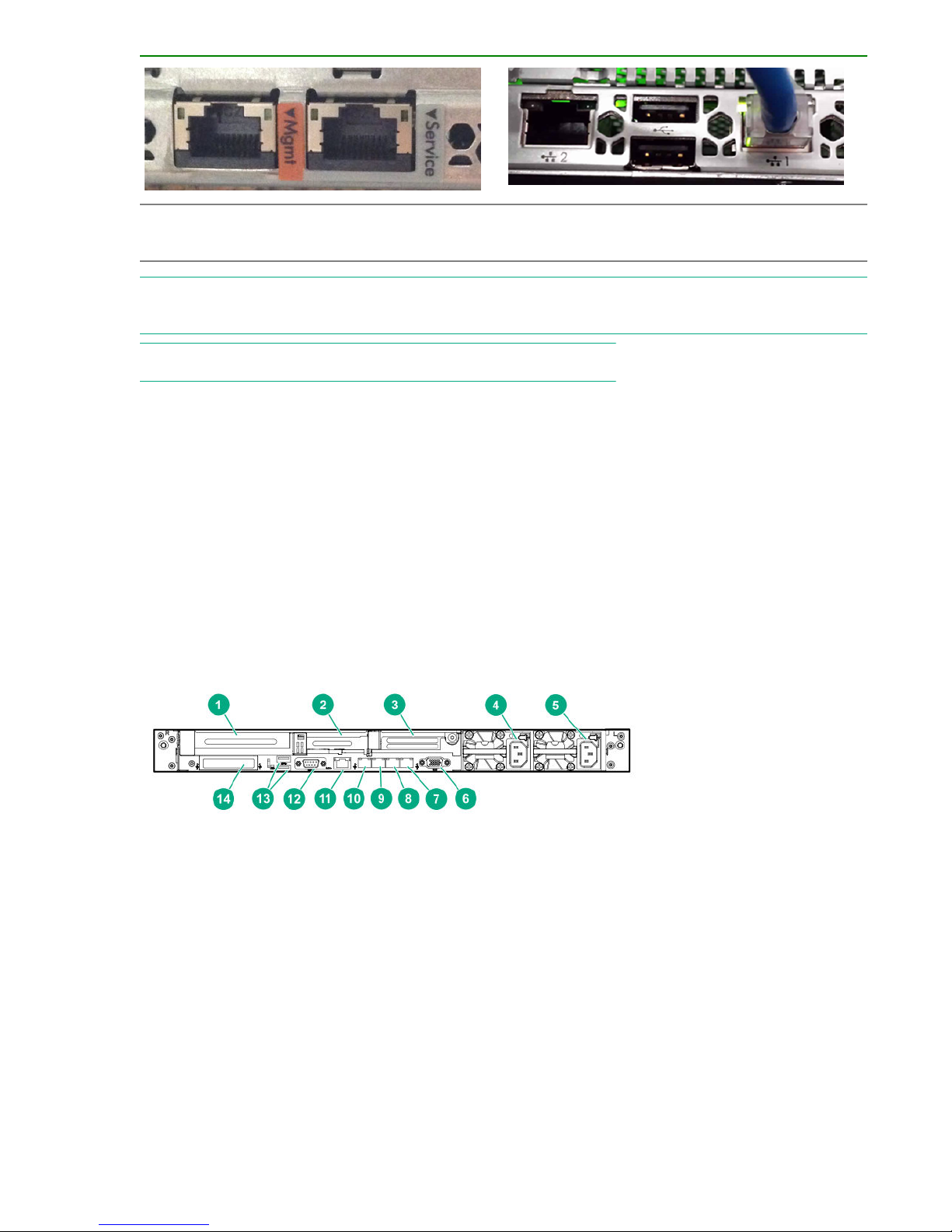
DL360 port configuration
The HPE ProLiant DL360 has a separate iLO Management port on the rear side and iLO Service Port on
the front side.
Alternatively, NIC connectors 1 and 2 are the Ethernet ports and can be used as Management port and
Service port respectively .
The port configuration for the DL360 Gen10 on the rear side is as follows:
1. Slot 1 PCIe3
2. Slot 2 PCIe3
3. Slot 3 PCIe3 (optional - requires second processor)
4. Power supply 2 (PS2)
5. Power supply 1 (PS1)
6. Video port
7. NIC port 4
8. NIC port 3
Introduction 7
Page 8
9. NIC port 2; Service port (Eth1)
10. NIC port 1; Management port (Eth0)
11. iLO Management Port
12. Serial port (optional)
13. USB 3.0 ports
14. FlexibleLOM (optional)
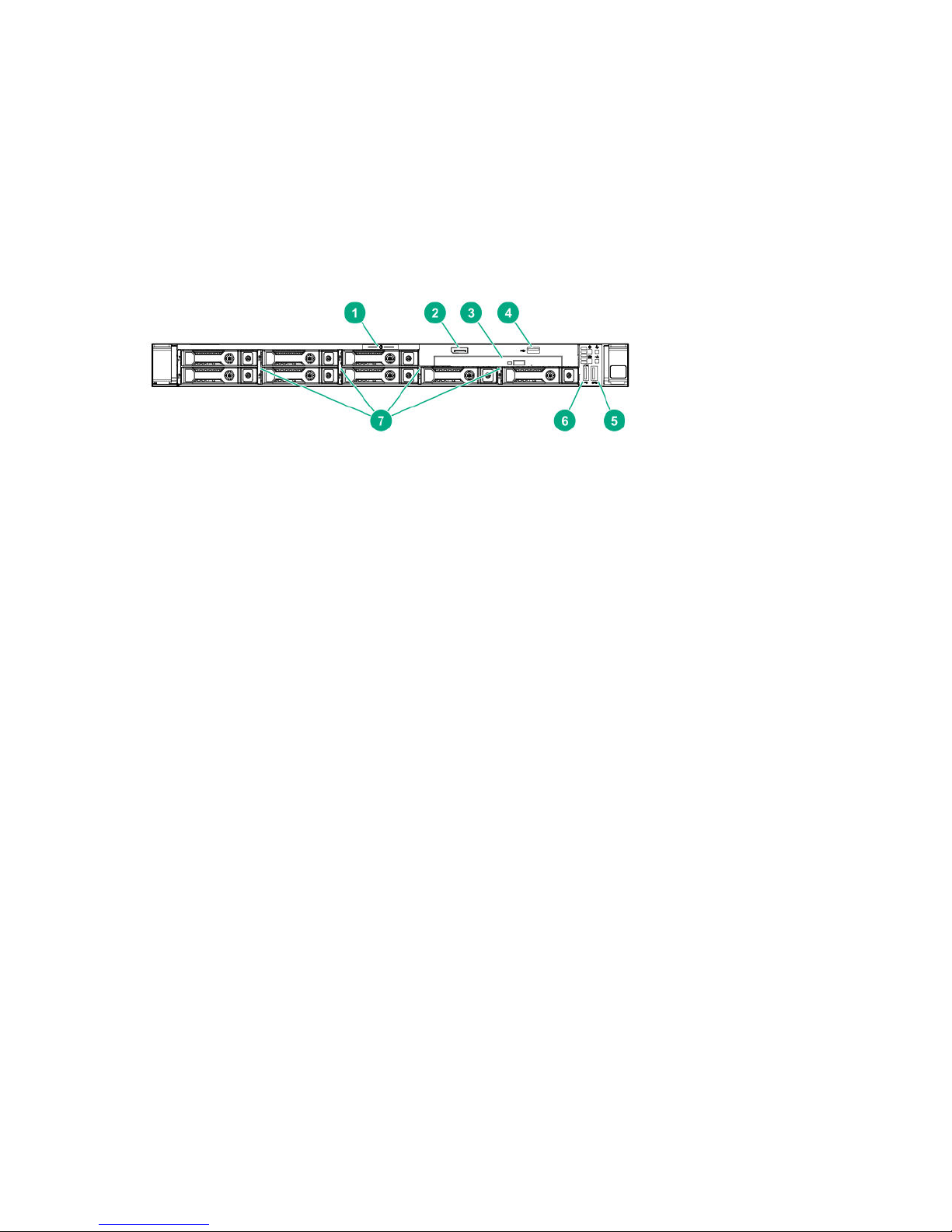
The port configuration for the DL360 Gen10 on the front side is as follows:
1. Serial label pull tab
2. Display port (optional)
3. Optical drive (optional)
4. USB 2.0 port (optional)
5. USB 3.0 port
6. iLO Service Port
7. SAS/SATA drive bays
The front side illustration shown above is for 8 LLF drive configuration and the location of Service Port
may vary depending on the configuration of the HPE DL360 Gen10 system.
8 Introduction
Page 9

Overview
The SP is available in both physical and virtual versions for the SP 4.4.0 release. The SP is designed to
provide remote error detection and reporting and to support diagnostic and maintenance activities
involving the storage systems. The SP is composed of a Linux operating system and the SP software,
and it exists as a single undivided entity.
The physical SP is a hardware device mounted in the system’s rack. If the customer chooses a physical
SP, each storage system installed at the operating site includes a physical SP installed in the same
cabinet as the system’s controller nodes. A physical SP uses two physical network connections; one
(eth0) requires a connection from the customer network in order to communicate with the storage system.
The other (eth1) is for maintenance purposes only and is not connected to the customer network.
NOTE:
Eth0 and eth1 are logical port numbers. Physical port numbers may vary by SP model.
The virtual SP (VSP) is provided in an Open Virtual Format (OVF) format. The VSP is tested and
supported on the VMware vSphere hypervisor (based on the ESXi 4.0 server and supported on VMware
ESX and ESXi 4.1 and later clients). It is also tested and supported on the Microsoft Hyper-V Server 2008
R2 and later hypervisor. The VSP has no physical connections. It runs on a customer-owned and
customer-defined server and communicates with 3PAR storage system over its own Ethernet
connections.
For information about how to use the VSP, see Virtual Service Processor on page 60. The VSP is
supported only for the HPE 3PAR StoreServ 7000 and 8000 Storage systems.
Customer Responsibilities
The customer must provide any hardware required to host the SP OS when deploying a VSP. For
scheduled service calls, the customer shall make the VSP available to Hewlett Packard Enterprise for
remedial activities at the agreed-upon time. The customer is responsible for maintaining the appropriate
HPE 3PAR Remote Support Technology with a secure connection to Hewlett Packard Enterprise and any
passwords required to access the local network and VSP. The customer is responsible for providing all
necessary resources in accordance with the HPE 3PAR Service Processor release notes in order to
enable the delivery of the service and options. For more information on requirements, specifications, and
exclusions, contact a local Hewlett Packard Enterprise representative.
NOTE:
To navigate to the Release Notes on the Hewlett Packard Enterprise Support Center website, select
Products and Solutions > 3PAR StoreServ Storage and then select Information Type > Getting
Started.
Service Processor Connectivity Overview
The data collected by the SP is used to maintain, troubleshoot, and upgrade the SP and the 3PAR
StoreServ Storage system. Only one storage system can be attached to an SP. Depending on the SP’s
connection mode, the SP communicates either with an HPE 3PAR Connection Portal or with the HPE
3PAR Collector Server.
NOTE: Beginning with SP-4.4.0 MU1, during system setup the SP can be set up in Secure Network Mode
only.
During system setup, the SP can be set up in either Secure Network mode (recommended) or SP mode.
In Secure Network mode, the SP communicates with the 3PAR Collector Server using HPE 3PAR Secure
Overview 9
Page 10

Service Agent software. In SP mode, the SP communicates with the 3PAR Connection Portal server via
Secure Shell (SSH) and SSH File Transfer Protocol (SFTP).
NOTE: Beginning with SP-4.4.0, older ciphers have been retired and the following new ciphers are
required:.
• AES-256-CTR
• AES-192-CTR
• AES-128-CTR
The connection between the SP and the connection portal can be made using your network and the
Internet or, for versions that are earlier than SP 4.1.0, a point-to-point connection with a modem.
Connections that use your network pass through your firewall, while connections that use a modem
bypass the firewall.
The 3PAR Secure Service Agent (SSA) enables the SP to communicate with the Collector Server. Unlike
direct SSH connections to your SP, with the SSA it is not necessary to open additional ports on your
firewall, because communications are performed with HTTPS.
Secure Network mode and SP mode are discussed further in the following sections.
Secure Network Mode Overview
In Secure Network mode, the SP communicates with the 3PAR Collector Server using the 3PAR Secure
Service Agent (SSA). The Collector server provides software updates, access to service tools
applications such as Service Processor Onsite Customer Care (SPOCC), and access to resources such
as the Hewlett Packard Enterprise Support Center (HSC) through SPOCC.
Rather than using a connection portal to connect to HPE 3PAR Central, an SP in Secure Network mode
requires the following for connection:
• 3PAR Secure Service Agent
The 3PAR Secure Service Agent (SSA) facilitates communication between the SP and Collector
server. Communications are done with HTTPS. For more information about the SSA, see Secure
Service Agent Overview on page 15.
• Administered communication policies using either HPE 3PAR Policy Server or Customer Controlled
Access (CCA)
◦ 3PAR Policy Server is an optional host application that administers the communication policies
between the SP and Collector server. For information about 3PAR Policy Server, see the 3PAR
Policy Server installation and setup guide.
◦ If you do not have Policy Server, you can use the CCA feature to administer communication
policies between the SP and the 3PAR Collector Server.
The following figure illustrates the relationship between the SP and 3PAR Central in Secure Network
mode.
10 Overview
Page 11

Network
HPE 3PAR CentralCustomer Site
HPE 3PAR
StoreServ
System
SP running
HPE 3PAR SSA
Host running
HPE 3PAR
Policy Server
HPE 3PAR
Collector
Server
Figure 1: SP-to-HPE 3PAR Central Relationship in Secure Network Mode
Network
HPE 3PAR Central
Customer Site
Connection Portal
HPE 3PAR
StoreServ
System
SP running
HPE 3PAR SSA
Connection
Portal
HPE 3PAR
Collector
Server
• For information about SPOCC, see SPOCC Overview on page 12.
• For information about SPMAINT, see SPMAINT Overview on page 13.
SP Mode Overview
NOTE: If the SP is running in Secure Network Mode, this section does not apply.
SP mode enables communication between an SP and the 3PAR connection portal server located at 3PAR
Central. The server provides software updates and SPOCC service tools applications. In SP mode, you
use the SPMAINT utility to support and maintain the SP and any connected system.
The following figure illustrates the relationship between SP and 3PAR Central in SP mode.
Figure 2: SP-to-HPE 3PAR Central Relationship in SP Mode
When a designated management workstation sits on the same network as the SP and is configured to
access the SP, you have the option of using external communications at any time using CCA, which is
accessible via SPMAINT.
Overview 11
Page 12

• For information about SPOCC, see SPOCC Overview on page 12.
• For information about SPMAINT, see SPMAINT Overview on page 13.
SPOCC Overview
Service Processor Onsite Customer Care (SPOCC) is a suite of service tool applications in a web-based
graphical user interface that is available for support of the 3PAR storage system and its SP. SPOCC
provides a vehicle to review logs and files, to store various types of support documentation, and to
manually record system configuration details that are not directly available from the system itself. SPOCC
offers a web-based alternative to accessing most of the features and functionality that are available
through SPMAINT.
One important feature offered by SPOCC that is not available through SPMAINT is the ability to create
subscription-based local notification lists. Local notification is designed primarily for those who want to be
automatically notified of specific events or symptoms from a particular system. SPOCC allows you to
enable or disable local notification and to manage how and when you are notified of important system
events.
SPOCC is a web-based interface and allows you to have several active sessions running at the same
time regardless of user privilege levels. By contrast, only one SPMAINT session is allowed at a time
through SPOCC or a CLI session.
There are many tasks that can be performed using either the SPOCC interface or the SPMAINT interface.
The SPOCC interface is the primary user interface available for the support of both the storage system
and its SP. For more information about SPOCC, see the HPE 3PAR Service Processor Onsite Customer
Care (SPOCC) User Guide.
This guide provides steps for performing tasks through SPOCC. When a task cannot be performed
through SPOCC, this guide shows you how to perform that task using SPMAINT.
Logging In to SPOCC
SPOCC is accessed through a management workstation, which is a machine that has been defined in the
SP’s public firewall rules. One or more management workstations are typically defined as part of the
installation and setup of the storage system and SP, as described in the installation/deinstallation guide
for your version of the 3PAR StoreServ Storage system.
To log in to SPOCC:
Procedure
1. Enter the IP address or hostname of the SP in the web browser, then press ENTER.
2. Enter your user ID and password, then click OK.
NOTE: For a current list of supported browsers for SPOCC, see the Single Point of Connectivity
Knowledge for HPE Storage Products (SPOCK), located at http://www.hpe.com/storage/spock.
Changing the SP Password Using SPOCC
To protect the SP against unauthorized access, Hewlett Packard Enterprise recommends that you change
the default passwords and maintain the new passwords so that they are available for support personnel.
To change the SP password:
12 Overview
Page 13

Procedure
1. Log in to SPOCC.
2. In the left navigation pane, click SPmaint.
3. Under Service Processor - SP Maintenance, click SP Control/Status.
4. Under Service Processor - SP Control Menu, click SP User Access Control.
5. Under Service Processor - SP User Access Control Menu, click Change User Password.
6. In the Select User list, select the user name whose password you want to change.
7. In the New Password field, enter the new password.
NOTE:
A valid password is between 7 and 32 characters long and uses only alphanumeric characters and the
following special characters:
• Period (.)
• Forward slash (/)
• Plus sign (+)
• Equals sign (=)
• Hyphen (-)
8. In the Confirm Password field, enter the new password again.
9. Click Change Password.
SPMAINT Overview
The SPMAINT utility is an interface for the support (configuration and maintenance) of both the storage
system and its SP. Use SPMAINT as a backup method for accessing the SP; SPOCC is the preferred
access method. In this guide, the features of the SPMAINT utility are divided into the following major
categories:
• Control of the SP (for more information, see SP Control/Status Functions on page 17)
• Network configuration (for more information, see Network Configuration on page 27)
• Setup and administration of local notification (for more information, see Local Notification Service on
page 45)
• Communications with 3PAR Central or a local service provider (for more information, see HPE 3PAR
Communication Settings on page 57)
CAUTION: Many of the features and functions that are available through SPMAINT can adversely
affect a running system. To prevent potential damage to the system and irrecoverable loss of data,
do not attempt the procedures described in this manual until you have taken all necessary
safeguards.
Overview 13
Page 14

Accessing SPMAINT
SPMAINT allows you to affect the current status and configuration of both the system and the SP. For this
reason, only one instance of SPMAINT can be run at a time on a given system.
To access SPMAINT:
Procedure
1. Add the hosts to the firewall or leave the firewall in Permissive mode. (Firewall settings can be
changed on the 2.3 menu of SPMAINT.)
2. Initiate an SSH session to establish a connection to your SP.
3. Enter your user name and password.
SPMAINT Interface
Use the SPMAINT terminal user interface to support both the system and its SP. The following figure
illustrates the SPMAINT interface.
SP0001400383
1 SP Main
HPE 3PAR Service Processor Menu
Transfer media: ethernet Transfer status: Ok
Enter Control-C at any time to abort this process
1 ==> SP Control/Status
2 ==> Network Configuration
3 ==> StoreServ Configuration Management
4 ==> StoreServ Product Maintenance
5 ==> Local Notification Configuration
6 ==> Site Authentication Key Manipulation
7 ==> Interactive CLI for a StoreServ
8 ==> Execute a command on a node
X Exit
The following information appears at the top of each SPMAINT menu:
• SP ID
—The SP ID uses one of several formats:
◦ 7-character SP ID---The literal “SP” string (2 characters) + 5 digits (for example, SP09997). This ID
format is used for legacy SPs.
◦ 12-character SP ID---
– The literal “SP000” string (5 characters) + the 3PAR StoreServ 7000 7-digit 3PAR serial number
that is located on a label affixed to the node enclosure (DCN1). The label is on a tab on the
back right of the enclosure near Power Cooling Module1 (PCM 1, the PCM on the right). For
14 Overview
Page 15

example, if the 3PAR StoreServ 7000 3PAR serial number is 1601234, the Service Processor ID
will be SP0001601234.
– The literal “SP” string (2 characters) + the Hewlett Packard Enterprise 10-character
alphanumeric StoreServ serial number. For example, if the StoreServ serial number is
HP10SN1234, the Service Processor ID will be SPHP10SN1234. If the StoreServ serial number
is 0123456789, the Service Processor ID will be SP0123456789.
In the figure above, the SP ID is “SP0001400383.”
• Menu name—Menu names are not necessarily unique. Menus that are accessible from the same
menu often share the same name as the menu itself.
In the figure above, the menu name is “SP Main.”
• Vector key code—A vector key code identifies each menu and submenu and many of the screens
available through SPMAINT. Use these codes to navigate quickly to a specific menu or function.
In the figure above, the vector key code is “1.” Submenus are denoted, for example, as “1.1,” “1.1.1,”
and so on.
• Transfer media—The Transfer Media field indicates the current method for outbound
communications.
In the figure above, the transfer media is “Ethernet.”
• Transfer status—The Transfer Status field indicates the status for the most recent data transfer
transaction.
In the figure above, the transfer status is “OK.”
Policy Server Overview
3PAR Policy Server is an optional host-based application that administers the communication policies
between the SP and Collector server. For information about 3PAR Policy Server, see the 3PAR Policy
Server installation and setup guide.
Secure Service Agent Overview
The 3PAR Secure Service Agent (SSA) is a software application that resides on the SP. SSA enables the
communication between the SP and the 3PAR Collector Server. Unlike direct SSH connections to your
SP, with the SSA there is no need to open additional ports on your firewall, because communications are
done with HTTPS.
The 3PAR SSA can be configured to communicate with the 3PAR Policy Server and one or more SPs
within your network as well as with Customer Support at 3PAR Central. The SSA serves as the
centralized communication point for all communications between your site and 3PAR Central. All
diagnostic data transfers and remote service connections that are established through the SSA are
secure and controlled by your network administrators. The SSA is configured for encrypted
communication through the Secure Socket Layer/Transport Layer Security (SSL/TLS) protocols.
Default User Accounts
This section describes the default user accounts that are created during the Moment of Birth (MOB)
operation of the SP and the Out of the Box (OOTB) operation of the storage system.
Default SP User Accounts
During the SP’s MOB operation, the following SP user accounts are created:
Overview 15
Page 16

• 3parcust is the default customer account. This account is not used by Hewlett Packard Enterprise
personnel and can be modified by the user. This account can be used to create new local SP users
and to access SPOCC. The 3parcust password should be changed by the customer.
• setupusr is used only for the initial system setup process to access the SP from the setup wizards.
After installation, the setupusr account password should be changed.
• spvar is used only by Hewlett Packard Enterprise personnel and authorized service providers to
perform service and diagnostic functions on the system. This account can be used to access SPOCC
and the SPMAINT utility (via SSH). The spvar password should be changed by the customer and
stored so that it can be shared with on-site Hewlett Packard Enterprise or authorized service
personnel during maintenance activities (and changed again afterwards).
Default CLI User Accounts
During the 3PAR storage system’s Out of the Box (OOTB) operation, the following HPE 3PAR CLI user
accounts are created:
• 3paradm is a user account with Super rights. This user account is not used by Hewlett Packard
Enterprise personnel and you can modify or delete this user account. Use the 3paradm user account
to create new CLI users. You should change the password of this user.
• 3parcim is a user account with Browse rights. This user account is reserved for use by the 3PAR
administration tools. The 3parcim user account and password must not be modified or deleted if you
intend to use CIM. If CIM will never be used, then the account may be modified or deleted.
• 3parbrowse is a user account with Browse rights. No Hewlett Packard Enterprise personnel or service
providers have access to this user account. The password is randomly created and is unknown to
anyone. This user account is not used by Hewlett Packard Enterprise personnel and you can modify or
delete this user account.
• 3paredit is a user account with Edit rights. No Hewlett Packard Enterprise personnel or service
providers have access to this user account. The password is randomly created and is unknown to
anyone. This user account is not used by Hewlett Packard Enterprise personnel and you can modify or
delete this user account.
• 3parsvc is a user account with Super rights. This Super user account is used by the SP to monitor the
3PAR storage system. The 3parsvc user account should not be removed. If the SP is being used to
monitor the storage server, the SP resets the default password to a randomized value. Changing the
password prevents the SP from performing monitoring operations. If the SP is not being used for
monitoring and is only used for maintenance activities, the password can be changed. When a
maintenance activity takes place, the password for 3parsvc should be set to a defined value; after the
maintenance, the SP changes the password to a randomized value again. Once the maintenance is
complete, the password can again be changed.
• 3parservice is a user account with Super rights. This Super user account is used by Hewlett Packard
Enterprise personnel and authorized service providers to perform service and diagnostic functions on
the system through the interactive CLI. The 3parservice user account should not be removed. The
password can be modified by the system administrator. During SP maintenance activities, the
password may be reset by the system to allow service to proceed. Once the maintenance is complete,
the password can again be changed.
16 Overview
Page 17

SP Control/Status Functions
The following sections describe various control functions and status checks that you can perform using
the SPMAINT interface.
NOTE:
Enhanced security features on the 3PAR StoreServ storage and the 3PAR Service Processor prevent
support for network address translation (NAT) between the SP and the 3PAR array.
NOTE:
The 20 , 21 , and 22 menu options on the 1–SP Control/Status menu cause a return to the SPMAINT
main menu if the number combinations for these options are entered (for example, 1.20, 1.21, or 1.22). To
avoid this, select each menu option one at a time.
Stopping and Starting System-Related Processes
This feature allows you to stop and start the spevent and spcollect processes for a particular system.
It may be useful as a diagnostic procedure to stop then start the system-related processes if you are
having problems with the SP communicating with the system.
Unlike what occurs in maintenance mode, the stopping of system-related processes does not attempt to
limit or accept events that can occur while system-related processes are stopped. When the processes
are restarted manually or as a result of restarting the SP, all pending collected data are transferred to
3PAR Central or an 3PAR Authorized Service Provider.
NOTE: Hewlett Packard Enterprise recommends that you do not leave the system-related processes
stopped for prolonged periods of time, as the system event log can roll.
To stop or start system-related processes using SPOCC:
Procedure
1. On the SPOCC home page, in the left navigation pane, click SPmaint.
2. Click SP Control/Status.
3. Click Stop StoreServ related SP Processes or Start StoreServ related SP Processes, then click
OK when prompted.
To stop or start system-related processes using SPMAINT:
1. From the SPMAINT main menu, enter 1 for SP Control/Status, then press ENTER.
2. Enter 4 for Stop StoreServ related Processes or 5 for Start StoreServ related Processes, then
press ENTER.
3. Select the system to stop or start related processes, then press ENTER.
4. When prompted, confirm the stopping of system-related processes.
Mounting and Unmounting Physical Media on the SP
You can use physical media to deploy a software update or 3PAR OS installation via the SP.
To mount or unmount physical media using SPOCC:
SP Control/Status Functions 17
Page 18

Procedure
1. On the SPOCC home page, in the left navigation pane, click SPmaint.
2. Click SP Control/Status.
3. Click Mount a CDROM or Unmount a CDROM.
To mount physical media using SPMAINT:
1. Insert a CD into the CD-ROM of the SP.
2. From the SPMAINT main menu, enter 1 for SP Control/Status, then press ENTER.
3. Enter 9 for Mount a CDROM from the SP main menu, then press ENTER.
4. When prompted, enter y, then press ENTER to mount the CD.
To unmount physical media using SPMAINT:
1. Enter 10 for Unmount a CDROM, then press ENTER.
2. When prompted, enter y, then press ENTER.
3. Remove the physical media from the media drive.
Resetting the Quiesce State in the Transfer Process
The transfer control process (SPtransfer) can quiesce itself for varying lengths of time because of errors
in transmission, a change in the state of the CCA, or for other purposes. Use the Reset Quiesce state in
Transfer process option on the SP Transfer Settings menu to force the SPtransfer command to quit its
quiesced state. This is mainly a diagnostic operation.
To force the transfer process to reset using SPOCC:
Procedure
1. On the SPOCC home page, in the left navigation pane, click SPmaint.
2. Click SP Control/Status.
3. Click Reset Quiesce State in Transfer Process.
To force the transfer process to reset using SPMAINT:
1. From the SPMAINT main menu, enter 1 for SP Control/Status, then press ENTER.
2. Enter 8 for Reset Quiesce state in Transfer process, then press ENTER.
NOTE: When using SPOCC or SPMAINT, this option does not display any menu output, even though the
signal is sent to the process. It is not necessary to confirm this action.
Administering an SP File Transfer Trigger
Use the SP File Transfer Trigger option on the SP Control menu to force the logging function on the SP to
switch to a new log and queue the old one for transfer to the connection portal. This is done mainly for
diagnostic purposes at the request of an 3PAR Authorized Service Provider or a local service provider.
To force a transfer trigger using SPOCC:
18 SP Control/Status Functions
Page 19

Procedure
1. On the SPOCC home page, in the left navigation pane, click SPmaint.
2. Click SP Control/Status.
3. Click SP Log Transfer Trigger, then click OK when prompted.
To force a transfer trigger using SPMAINT:
1. From the SPMAINT main menu, enter 1 for SP Control/Status, then press ENTER.
2. From the File/Log Transfer menu, enter 7 for SP File Transfer Trigger, then press ENTER.
The following options appear:
• 1—Transfer SP log
• 2—Take a SPLOR
• 3—Do both 1 and 2
• 4—Transfer a file held for size
• 5—Configure FTP Proxy
3. Enter 1, then press ENTER to confirm the transfer.
To create a Service Processor Log Out Request (SPLOR) and transfer, enter 19, then press ENTER. The
SPLOR creates a diagnostic archive of data related to the SP state and configuration.
Managing Date and Time Settings
You can use SPOCC or SPMAINT to configure the date, time, time zone, and location for the SP.
CAUTION: If you are using a network time protocol (NTP) server, do not change the time setting for
the SP unless the SP is not synchronized with the NTP server.
To manage these settings in SPOCC, use the SP Date/Time/Location submenu:
Procedure
1. On the SPOCC home page, in the left navigation pane, click SPmaint.
2. Click SP Control/Status.
3. Click SP Date/Time/Geographical Location.
4. To configure the date, time, or both, click SP Date/Time Maintenance.
5. Configure the Date, Time, and Timezone fields, then click Update System Date and Time.
6. Click SP DateTimeLoc Menu to return to the SP Date/Time/Geographical Location menu.
7. To configure the geographic location, click Geographical Location (Modem Control).
8. Select your location from the Geographic Location list, then click Update Geographical Location.
To manage these settings in SPMAINT, use the SP System Date/Time submenu:
SP Control/Status Functions 19
Page 20

1. From the SPMAINT main menu, enter 1 for SP Control/Status, then press ENTER.
2. Enter 11 for SP Date/Time/Geographical Location maintenance, then press ENTER.
The following subsections describe how to perform the tasks that are related to each of the functions that
are available through the SP System Date/Time/Geographical Location submenu in SPMAINT.
Changing the Date in SPMAINT
To change the SP date:
Procedure
1. From the SP System Date/Time submenu, enter 1 for Change the Date, then press ENTER.
2. When prompted, enter the new date in YYYY/MM/DD format, then press ENTER.
3. When prompted, enter y, then press ENTER to confirm the date change.
Changing the Time in SPMAINT
To change the SP time:
Procedure
1. From the SP System Date/Time submenu, enter 2 for Change the Time, then press ENTER.
2. When prompted, enter the new time in 24-hour format (HH:MM), then press ENTER.
3. When prompted, enter y, then press ENTER to confirm the time change.
Changing the Time Zone in SPMAINT
If you are altering the time zone setting for the SP, respond to the following guided menus, then press
ENTER to confirm the following information:
• Continent or ocean
• Country
• Time zone region
Verify or set the date and time before continuing.
To change the time zone setting:
Procedure
1. From the SP System Date/Time submenu, enter 3 for Change the timezone, then press ENTER.
2. When prompted, enter y, then press ENTER to launch the time zone configuration sequence.
Managing NTP Configuration
Use the Network Time Protocol (NTP) Configuration submenu in SPOCC to manage the NTP and NTP
server configuration settings (this submenu is called the Manage NTP Configuration [NTPCONF]
submenu in SPMAINT).
20 SP Control/Status Functions
Page 21

The SP serves the NTP for any attached systems. This can be a closed time domain (SP and systems),
or the NTP can be a client of any number of customer NTP servers.
To access the NTP Configuration submenu in SPOCC:
Procedure
1. On the SPOCC home page, in the left navigation pane, click SPmaint.
2. Click SP Control/Status.
3. Click Manage NTP configuration.
4. Click Delete, Add NTP Server Host, or View Complete NTP Status.
To access the NTPCONF submenu using SPMAINT:
1. From the SPMAINT main menu, enter 1 for SP Control/Status, then press ENTER.
2. Enter 12 for Manage NTP Configuration, then press ENTER.
The subsections that follow describe how to use SPMAINT to perform tasks related to each of the
functions that are available through the NTPCONF submenu.
Displaying the NTP Configuration Using SPMAINT
To display the current SP NTP configuration:
Procedure
1. From the NTPCONF submenu, enter 1 for Display NTP Configuration, then press ENTER.
2. Press ENTER to return to the NTPCONF submenu.
NOTE: The output displays the content of the NTP configuration ntp.conf file that shows the running
parameters for the active NTP instance on the SP.
Adding an External NTP Server Using SPMAINT
To add an external NTP server to the SP NTP configuration settings:
Procedure
1. From the NTPCONF submenu, enter 2 for Add external NTP server, then press ENTER.
2. When the NEWNTP menu appears, enter the IP address for the NTP server, then press ENTER.
3. When prompted, confirm the addition of the new NTP server.
Removing an External NTP Server Using SPMAINT
To remove an existing external NTP server from the SP NTP configuration settings:
SP Control/Status Functions 21
Page 22

Procedure
1. From the NTPCONF submenu, enter 3 for Remove external NTP server, then press ENTER.
2. Enter the number that corresponds to the external NTP server that is set to be deleted from the SP
configuration settings, then press ENTER.
3. When prompted, enter y, then press ENTER to confirm the NTP server configuration removal.
Defining the SP Process Control Parameters
The SP Process Control Parameters function allows you to view and modify the content of some process
control variables. Mainly, these parameters control the transfer and handling of data that is destined for
the connection portal. You can access the control parameters through SPOCC or SPMAINT.
CAUTION: Hewlett Packard Enterprise recommends that you do not change the default process
control parameters unless advised to do so by an HPE Technical Services support technician.
To access the SP Process Control Parameters submenu using SPOCC:
Procedure
1. On the SPOCC home page, in the left navigation pane, click SPmaint.
2. Click SP Control/Status.
3. Click SP Process Control Parameters.
On the SP Process Control Parameters submenu, you are presented with numerous configuration
options, which are described in the following table.
Control parameter name Description
Max Days Between Transfer Perform a transfer at least as frequently as this
number of days.
Transfer Files during Remote Ops Controls whether files are transferred over modem
when Remote Operation is active.
Break Large Files Controls the breaking down of large files for
transfer.
Max File Size before File Split (Kb) — Eth Maximum size, in kilobytes, of a file to transfer over
Ethernet.
File Split Size (Kb) — Eth When a file’s size exceeds the maximum Ethernet
size, break the file down into parts this size, in
kilobytes.
Max File Size to Transfer (MB) — Eth Maximum size, in megabytes, of a file queued for
transfer via Ethernet.
Group Small Files Controls the grouping of small files for transfer.
22 SP Control/Status Functions
Larger files are kept for 14 days.
Table Continued
Page 23

Control parameter name Description
Max Files in Group Maximum number of files that can be grouped
together for transfer.
Scrub Weekly Files (replaced with Enable Scrubber
option starting SP-4.4.0 MU4)
Enable scrubber (replaces Scrub weekly files
option starting SP-4.4.0 MU4)
Max Files before Transfer Perform a transfer when this number of files are
Filetypes to Transfer First File types that should be transferred first (there is a
FIFO/LIFO Use Last In First Out (LIFO) when selecting the
Max File Size before File Split (Kb) — Modem Maximum size, in kilobytes, of a file to transfer over
File Split Size (Kb) — Modem When a file’s size exceeds the maximum modem
Max File Size to Transfer (MB) — Modem Maximum size, in megabytes, of a file queued for
Perform a weekly file scrub.
Perform real time scrubbing of files.
queued.
maximum of five file types, and they should be in a
comma-separated list).
next file to transfer.
modem.
size, break the file down into parts this size, in
kilobytes.
transfer via modem.
Larger files are kept for 14 days.
Delay Before Closing Group Wait this number of seconds before closing the
current file group.
The following section describes the file transfer options and how to modify them using SPMAINT.
Editing File Transfer Processes using SPMAINT
NOTE: These values should be changed only with guidance from an authorized Hewlett Packard
Enterprise support provider.
To access the SP Process Control Parameters submenu using SPMAINT:
Procedure
1. From the SPMAINT main menu, enter 1 for SP Control/Status, then press ENTER.
2. Enter 15 for SP Process Control Parameters, then press ENTER.
Use the SP Process Control Parameters submenu to edit the file transfer processes parameters for the
SP.
SP Process Control Parameters lists all parameters by ID number, provides their default values, and
notes how they are impacted when their values are edited.
SP Control/Status Functions 23
Page 24

Table 1: SP Process Control Parameters
ID Default Value Notes
1 False Use Last In First Out (LIFO) when selecting the next file to
transfer.
2 1 Perform a transfer when this number of files are queued.
3 15 Perform a transfer at least as frequently as this number of
days.
4 1024 Maximum size, in megabytes, of a file queued for transfer via
modem. Larger files are kept for 14 days.
5 65536 Maximum size, in megabytes, of a file queued for transfer via
Ethernet. Larger files are kept for 14 days.
6 True Controls the breaking down of large files (see the next four
parameters).
7 10485760 Maximum size, in kilobytes, of a file to transfer over modem.
8 10485760 When a file’s size exceeds the maximum modem size, break
the file down into parts this size, in kilobytes.
9 536870912 Maximum size, in kilobytes, of a file to transfer over Ethernet.
10 536870912 When a file’s size exceeds the maximum Ethernet size, break
the file down into parts this size, in kilobytes.
11 True Controls whether files are transferred over modem when
Remote Operation is active.
12 NONE File types that should be transferred first (there is a maximum
of five, and they should be in a comma-separated list).
13 True Controls the grouping of small files for transfer.
14 50 Maximum number of files that can be grouped together for
transfer.
15 60 Wait this number of seconds before closing the current file
group.
To edit the file transfer process parameters on the SP:
1. From the SP Process Control submenu, enter 1 for Alter Process Control Parms, then press
ENTER.
The screen displays the current file transfer process settings.
2. Enter the number corresponding to the process that you want to reconfigure, then press ENTER.
3. Enter the ID number corresponding to the parameter that is selected for editing, then press ENTER.
24 SP Control/Status Functions
Page 25

4. Enter a new value for the parameter, then press ENTER.
5. You are prompted to enter additional parameter IDs.
6. When you are finished editing parameters, enter 0, then press ENTER.
7. When prompted, enter y, then press ENTER to save and activate your changes.
Saving and activating your changes automatically returns you to the SP Control submenu.
Running a SPLOR or an MSPLOR
To collect data to diagnose SP issues, run a Service Processor Log Out Request (SPLOR). To collect
data to diagnose SP installation issues, run a Mini Service Processor Log Out Request (MSPLOR).
To run a SPLOR using SPOCC:
Procedure
1. On the SPOCC home page, in the left navigation pane, click Support.
2. Under Service Processor, click Launch SPLOR. The SPLOR opens in a new window.
3. When the SPLOR is complete, click View SPLOR Contents.
To run a SPLOR using SPMAINT:
1. From the SPMAINT main menu, enter 1 for SP Control/Status, then press ENTER.
2. Enter 19 for Take a SPLOR, then press ENTER.
3. Once finished, press ENTER to continue.
To run an MSPLOR:
1. From the SPMAINT main menu, enter 1 for SP Control/Status, then press ENTER.
2. Enter 20 for Take an MSPLOR, then press ENTER.
3. Once finished, press ENTER to continue.
Running SP Check Health
The SP Check Health feature detects whether a storage system has duplicate IP addresses. To run the
SP Check Health feature using SPOCC:
Procedure
1. Click Support in the left navigation pane.
2. Click Health Check from the list of StoreServ actions. A pop up box appears showing progress while a
report is generated.
3. The report appears in a new browser window.
To run the SP Check Health feature using SPMAINT:
SP Control/Status Functions 25
Page 26

1. From the SPMAINT main menu, enter 1 for SP Control/Status, then press ENTER.
2. Enter 21 for Run SP Check health, then press ENTER. The results are displayed.
3. Press ENTER to continue.
26 SP Control/Status Functions
Page 27

Network Configuration
NOTE: The SP and StoreServ must be on the same subnet during setup and installation. The SP has an
algorithm that uses the StoreServ serial number to initiate communication using a link local address
before the StoreServ is assigned an IP address. This is how the SP discovers the StoreServ, connects,
and performs setup. Link local address only works within the same subnet.
• When a StoreServ has an IP address, communication between the SP and StoreServ across the
subnet is not supported.
• Hewlett Packard Enterprise recommends that the SP and StoreServ remain on the same subnet for
optimal performance.
Configuring the Network for the Service Processor
The SP Network submenu of the SPMAINT utility allows you to manage the network and dialup settings
for the SP.
NOTE: Modem support is available only for systems that are earlier than SP 4.1.0.
To access the SP Network submenu:
Procedure
1. Log in to the SP as the spvar or 3parcust user.
2. Enter 2 for Network Configuration, then press ENTER.
3. Enter 4 for Change Public Network Interface Parameters, then press ENTER.
The current values are displayed along the right column. As you edit the values displayed in this menu,
the new values appear to the right of the current values. Modifications made with this submenu are not
permanent until you save or activate them from this menu using menu option A. The modifications are not
retained if you exit this menu without saving or activating them.
Configuring the Firewall
The SP Control FW (Firewall) submenu allows you to display and alter the status of the SP resident
firewall.
Displaying Firewall Status
To access the SP firewall control options through SPOCC:
Procedure
1. Log in to SPOCC as the 3parcust user.
2. On the SPOCC home page, in the left navigation pane, click SPmaint.
3. Click Network Configuration.
4. Click Firewall Manipulation.
5. Configure the firewall options.
Network Configuration 27
Page 28

To access the SP Control firewall submenu in SPMAINT, select the following menu options from the
SPMAINT main menu:
1. Enter 2 for Network Configuration, then press ENTER.
2. Enter 3 for Firewall Manipulation, then press ENTER.
3. Enter 1 for Display Firewall Status, then press ENTER.
Disabling Permissive Mode
By default, Permissive mode is enabled for the firewall. For increased security, you can disable
Permissive mode using either SPMAINT or SPOCC. Before disabling Permissive Mode, you must first
add at least one host to the firewall to access SPMAINT or SPOCC.
NOTE: Only the 3parcust user can change firewall rules in Secure Network Mode.
To disable Permissive mode using SPMAINT:
Procedure
1. On the SPMAINT home page, enter 2 for Network Configuration.
2. Enter 3 for Firewall Manipulation.
3. Enter 3 for Alter Public network firewall rules.
4. Enter 1 for Add a new host and then enter the new host IP address in the form 111.111.111.111,
111.111.111.024, or 111.111.111.22–123.
5. Enter y to confirm, and then press Enter to continue.
6. Enter x to return to the previous menu.
7. Enter 6 for Toggle Permissive Public Firewall (currently ON).
8. Enter y to confirm disabling Permissive Mode.
To disable Permissive mode using SPOCC:
1. In the left navigation pane, click SPMaint.
2. Click Network Configuration.
3. Click SP Firewall Control.
4. Click Add Public Host.
5. Enter the host IP address using the format shown on the Add Public Host IP Address page and then
click Add IP Address.
6. Click Disable Permissive Mode.
Changing the Public Network Interface Parameters
Changing the SP Default Route
Changing the SP default route affects the network setting for handling routing decisions to destinations
that are not local to the SP. The SP default route is the communication link to a proxy host or the outside
28 Network Configuration
Page 29

world. Typically, the same host is designated as the gateway (for more information, see Changing the SP
Default Gateway on page 30).
NOTE: The SP default route is not intended to be used as an alternate or backup route. Alternate and
backup routes are not configured on the SP.
To change the SP default route using SPOCC:
Procedure
1. On the SPOCC home page, in the left navigation pane, click SPmaint.
2. Click Network Configuration.
3. Click Change Public Network Interface Parameters.
4. Enter a new default route in the Default Route field, then click Save and Activate.
To change the SP default route using SPMAINT:
1. From the SPMAINT main menu, enter 2 for Network Configuration, then press ENTER.
2. Enter 4 for Change public network interface parameters, then press ENTER.
3. Enter 2 for Change Default Route, then press ENTER.
4. Enter a new default route, then press ENTER.
5. The SP Network submenu appears. The new default route is displayed to the right of the current
default route. Enter A, then press ENTER to quit, save, and activate the new default route.
Changing the SP IP Address
To change the SP’s IP address using SPOCC:
Procedure
1. On the SPOCC home page, in the left navigation pane, click SPmaint.
2. Click Network Configuration.
3. Click Change Public Network Interface Parameters.
4. Enter a new IP address in the IP Address field, then click Save and Activate.
To change the SP’s IP address using SPMAINT, select the following menu options from the SPMAINT
main menu:
1. From the SPMAINT main menu, enter 2 for Network Configuration, then press ENTER.
2. Enter 4 for Change public network interface parameters, then press ENTER.
3. Enter 3 for Change IP Address, then press ENTER.
4. From the Modify SP IP menu, enter a new IP address, then press ENTER.
5. The SP Network submenu appears, and the new IP address appears to the right of the current IP
address. Enter A, then press ENTER to quit, save, and activate the new IP address.
Network Configuration 29
Page 30

Changing the SP Netmask
To change the SP netmask using SPOCC:
Procedure
1. On the SPOCC home page, in the left navigation pane, click SPmaint.
2. Click Network Configuration.
3. Click Change Public Network Interface Parameters.
4. Enter a new netmask in the Netmask field, then click Save and Activate.
To change the SP netmask using SPMAINT, enter the following menu options from the SPMAINT main
menu:
1. From the SPMAINT main menu, enter 2 for Network Configuration, then press ENTER.
2. Enter 4 for Change public network interface parameters, then press ENTER.
3. Enter 4 for Change Netmask, then press ENTER.
4. The Modify Netmask menu appears. Enter a new netmask, then press ENTER.
Changing the SP Default Gateway
The IP address of the device on the local (public) network segment (or subnet) acts as a route to the rest
of your network. Typically, the IP address of the device is the same address as the default route (see
Changing the SP Default Route on page 28). However, for some networks, where Routing Information
Protocol (RIP) is disallowed, it may be necessary to define a separate device for this function.
NOTE: The SP default gateway is not intended to be used as an alternate or backup route. Alternate and
backup routes are not configured on the SP.
To change the SP default gateway using SPOCC:
Procedure
1. On the SPOCC home page, in the left navigation pane, click SPmaint.
2. Click Network Configuration.
3. Click Change Public Network Interface Parameters.
4. Enter a new gateway IP address in the Gateway field, then click Save and Activate.
To change the SP default gateway using SPMAINT:
1. From the SPMAINT main menu, enter 2 for Network Configuration, then press ENTER.
2. Enter 4 for Change public network interface parameters, then press ENTER.
3. Enter 5 for Change Gateway, then press ENTER.
4. Enter a new gateway, then press ENTER.
5. The SP Network submenu appears, and the new default gateway address appears to the right of the
current gateway address. Enter A, then press ENTER to quit, save, and activate the new default
gateway address.
30 Network Configuration
Page 31

Changing Transfer Media Settings
Use the SP Transfer Media submenu to alter the settings for the media the SP uses when communicating
with its associated connection portal.
NOTE: You cannot change the transfer media settings in Secure Network Mode. This includes all A-class
systems.
The following settings can be found in the SP Transfer Media submenu:
• Data Transfer involves external communications between the SP and the connection portal.
• Remote Operations include problem solving and diagnostics performed from a remote location.
To access the SP Transfer Media submenu using SPOCC:
Procedure
1. On the SPOCC home page, in the left navigation pane, click SPmaint.
2. Click Network Configuration.
3. Click Change Transfer Media.
4. To change the method of data transfer, select Ethernet, Modem, or Off, then press ENTER.
To access the SP Transfer Media submenu using SPMAINT:
1. From the SPMAINT main menu, enter 2 for Network Configuration, then press ENTER.
2. Enter 5 for Change Transfer Media/SP Phone Number from the Networks menu, then press ENTER.
3. Enter 1 for Data Transfer, then press ENTER.
4. To change the method of data transfer, select Ethernet, Modem, or Off, then press ENTER.
The following subsections describe how to perform tasks related to each of the functions available
through the SP Transfer Media submenu.
Changing the Transfer Media
Use this option to alter the media that the SP uses for sending an event or alert data and related files to a
connection portal.
To change the transfer media in SPMAINT:
Procedure
1. From the SP Transfer Media submenu, enter 1 for Data Transfer, then press ENTER.
2. When the SP Transfer Media Configuration menu appears, enter E|e, M|m, or O|o, then press
ENTER. The SP Transfer Media submenu appears.
NOTE:
The SP Transfer Media submenu may show additional items. Changed options appear to the right of
the current values.
Network Configuration 31
Page 32

3. Make any additional changes to the SP phone number and dial-in prefix as necessary.
4. When finished, enter A, then press ENTER to quit, save, and activate the new transfer media settings.
Changing the Remote Operations Transfer Media
Use this option to alter the media the SP uses when conducting problem-solving activities and diagnostics
performed from a remote location.
To change the remote operations transfer media:
Procedure
1. From the SP Transfer Media submenu, enter 2 for Remote Operations, then press ENTER.
The SP Transfer Media Configuration menu for remote operations appears.
2. Enter E|e for Ethernet, M|m for modem, or O|o for off, then press ENTER.
The SP Transfer Media submenu appears.
NOTE: The SP Transfer Media submenu may show additional items. Changed options appear to the
right of the current values.
3. Make any additional changes to the SP phone number and dial-in prefix, if applicable.
4. When task is complete, enter A, then press ENTER to quit, save, and activate the new remote
operations transfer media settings.
32 Network Configuration
Page 33

StoreServ Configuration Management
The StoreServ Configuration Management menu in SPMAINT includes the following options:
• Info—Display StoreServ information
• Add a new StoreServ—Add a new StoreServ
• Modify—Modify StoreServ config parameters
• Remove—Remove a StoreServ
Modify StoreServ Configuration Parameters
SP0XXXX
3.3.IN MODIFYCONF
HPE 3PAR Service Processor Menu
Transfer media: ethernet Transfer status: Ok
SP - StoreServ Configuration Manipulation
Enter Control-C at any time to abort this process
MODIFY StoreServ CONFIG FOR xx.xxxx.xxxx
WARNING: changes will not be verified against the running
StoreServ. Errors must be corrected manually!
Enter the number of the item you wish to change
1) IP Address: xxx.xxx.xx.xxx
2) System Name: SP0XXXX
3) Serial Number: XXXXXXX
System ID: XXXX
4) HPE 3PAR OS Level: x.x.x.xxx
5) Site Key Present: NO
6) Maintenance Mode: OFF
X) Exit without saving changes
S) Save changes then exit
Maintenance Mode Overview
The Maintenance Mode setting is used to control communication between the 3PAR StoreServ and 3PAR
Support. It is set automatically during 3PAR OS update and when performing CLI functions.
• Updating the HPE 3PAR OS—During the update, Maintenance Mode is turned on automatically and
then turned back off at the end of the upgrade, even if the upgrade fails.
• Performing CLI functions—Maintenance Mode is turned on automatically during CLI functions. It
turns off automatically when you exit the SPMAINT menu.
NOTE: Using Ctrl+C to exit or after a timeout, Maintenance Mode stays on for the default duration of 4
hours unless it is manually turned off.
StoreServ Configuration Management 33
Page 34

Add vCenter to the StoreServ
NOTE: Starting with SP 4.4 MU8 release, VmCollect is referred to as Cross Stack Analytics.
NOTE: This option is available only with SP version 4.4 MU7 and later as a part of Cross Stack Analytics
feature of the SP.
NOTE: If the SP is configured with SSA and Policy Server is not configured on SP, you cannot add
vCenter to the Storage system attached to the SP.
NOTE: If the SP is configured with SSA and Policy Server is configured on SP, after adding vCenters to
the Storage system policy server cannot be removed from the configuration. To remove the Policy server,
you must remove the vCenters first.
NOTE: HPE recommends that VSP is allocated with 4 GB of Memory and four CPU cores before adding
vCenter to the storage system attached to the VSP.
NOTE: If SP is at a version 4.4. MU5 or earlier, do not increase the CPU cores as multiple CPU cores are
not supported.
SP 4.4 MU7 and later provides an option to add vCenter to the newly added or existing StoreServ
Storage System where this vCenter has a data store from this Storage System. The Cross Stack
Analytics feature of the SP version 4.4 MU7 and later enables addition of vCenter to the storage system.
This feature also helps to collect daily configuration data of the vCenter and hourly performance data (for
CPU, memory, latency, and so on) for all the VMs hosted on ESX of the vCenter.
SP supports following vCenter versions:
• ESXi 5.5
• ESXi 6.0
• ESXi 6.5
• ESXI 6.7
NOTE: If StoreServ Storage System attached to the SP is removed, all the vCenters added to it are
removed automatically.
NOTE: When CA certificates are imported on the SP where vCenter is already added, all processes
related to Cross Stack Analytics feature are stopped. To avoid this, add vCenter only after importing the
CA certificates on the SP. If vCenter is already added to the SP, then after importing the CA certificates
reboot the SP.
NOTE: If all vCenters added to the StoreServ Storage System are removed, the collection of
configuration data and performance data stops. If vCenter is added later to the StoreServ Storage
System, the collection starts again.
NOTE: If StoreServ Storage System with vCenter added is updated, the collection of configuration data
and performance data stops before the update. The collection starts again after the update is complete.
34 StoreServ Configuration Management
Page 35

NOTE: With IE version 11.0.9600.19129, when you try to add vCenter to the SP through SPOCC; system
is unresponsive and vCenter is not added to the SP. Update the IE to11.2248.14393.0. and try adding
vCenter again or use Firefox to add vCenter to the SP.
Using SPOCC, you can add a StoreServ Storage system to SP and add vCenter to the existing Storage
system or newly added Storage System.
Add vCenter to the new StoreServ
SPOCC provides an option to add vCenter while adding a new StoreServ Storage system to SP.
Procedure
1. Connect to SPOCC with the SP IP address. Enter the SP IP address into a supported browser and
login with a valid username and password.
2. In the left navigation pane, click SPmaint.
3. Under Service Processor - SP Maintenance, click StoreServ Configuration Management.
4. Under Service Processor - StoreServ Configuration, click Add StoreServ.
5. Enter the IP address and the Super user credentials (account and password).
StoreServ Configuration Management 35
Page 36

6. Optional: To add vCenter, Click Add vCenter.
a. Enter the vCenter name, vCenter hostname or IP address, port number, and user credentials for
specified vCenter.
NOTE: The vCenter name can be up to 32 characters and can contain only alphabets (A-Z, a-z),
numbers (0-9), and special characters underscore (_) and hyphen (-). vCenter name cannot have
any other special characters.
IMPORTANT: If you are using SP 4.4 MU7, do not provide vCenter name as vCenter.
Optional: You can add description of the vCenter.
NOTE: The description of the vCenter can be up to 120 characters.
b. Do one of the following:
• Add—The vCenter is added and the details are displayed on the StoreServ page.
• Add+—The current vCentre is added and you can proceed with adding another vCenter.
• Cancel—The vCenter addition task is cancelled.
36 StoreServ Configuration Management
Page 37

c. After you add the vCenter, options specific to that vCenter are displayed:
• Info—When you click this option, a screen appears that provides configuration information for
the vCenter.
• Modify—When you click this option, a screen appears with fields that you can modify as
needed to change the configuration information.
CAUTION: If you are using SP 4.4 MU7 and if you want to modify the name of the
vCenter, do not provide the name of any other existing vCenter as the new name.
• Remove—When you click this option, a message appears that asks you to confirm that you
want to remove the vCenter.
StoreServ Configuration Management 37
Page 38

It also provides status of the vCenter as connected or inactive. If it is inactive, click the link to get
more details about the inactive state.
The connection status of vCenter is checked every 30 minutes. If any vCenter goes in inactive
state, a notification email is sent to appropriate user.
To add multiple vCenters to the Storage system, repeat this step.
7. Click Add StoreServ.
The StoreServ and vCenter is added to the SP.
38 StoreServ Configuration Management
Page 39

8. After you add the storage system, options specific to the storage system are displayed:
• Info—When you click this option, a screen appears that provides configuration information for the
storage system.
• Modify—When you click this option, a screen appears with fields that you can modify as needed to
change the configuration information.
NOTE: In SP 4.4.0 and later, the Serial Number field cannot be modified.
• Remove—When you click this option, a message appears that asks you to confirm that you want to
remove the storage system.
If the Storage system is removed from the SP, all the vCenters added to it are deleted
automatically.
Add vCenter to the existing StoreServ
SPOCC provides an option to add a vCenter to the StoreServ Storage system attached to SP.
Procedure
1. Connect to SPOCC with the SP IP address. Enter the SP IP address into a supported browser and
login with a valid username and password.
2. In the left navigation pane, click SPmaint.
3. Under Service Processor - SP Maintenance, click StoreServ Configuration Management.
4. Click Add vCenter.
StoreServ Configuration Management 39
Page 40

5. Enter the vCenter name, vCenter hostname or IP address, port number, and user credentials for
specified vCenter.
NOTE: The vCenter name can be up to 32 characters and can contain only alphabets (A-Z, a-z),
numbers (0-9), and special characters underscore (_) and hyphen (-). vCenter name cannot have any
other special characters.
IMPORTANT: If you are using SP 4.4 MU7, do not provide vCenter name as vCenter.
Optional: You can add description of the vCenter.
NOTE: The description of the vCenter can be up to 120 characters.
6. Do one of the following:
• Add—The vCenter is added and the details are displayed on the StoreServ page.
• Add+—The current vCenter is added and you can proceed with adding another vCenter.
• Cancel—The vCenter addition task is canceled.
40 StoreServ Configuration Management
Page 41

7. After you add the vCenter, options specific to that vCenter are displayed:
• Info—When you click this option, a screen appears that provides configuration information for the
vCenter.
• Modify—When you click this option, a screen appears with fields that you can modify as needed to
change the configuration information.
• Remove—When you click this option, a message appears that asks you to confirm that you want to
remove the vCenter.
StoreServ Configuration Management 41
Page 42

It also provides status of the vCenter as connected or inactive. If it is inactive, click the link to get more
details about the inactive state.
The connection status of vCenter is checked every 30 minutes. If any vCenter goes in inactive state, a
notification email is sent to appropriate user.
42 StoreServ Configuration Management
Page 43

StoreServ Product Maintenance
The StoreServ Product Maintenance menu in SPMAINT includes the following options:
• Retrieve Application Core Files
• Retrieve System Crash Dumps
• Retrieve InSplore Data
1
• Request a File Persona Comprehensive Collection
• Retrieve File Persona Automatic Collections
• Retrieve File Persona Live Dumps
• Reboot a StoreServ Cluster/Node
• Halt a StoreServ Cluster/Node
• Upgrade HPE 3PAR OS
• Update Cage Firmware
• Update Drive Code
• Node Rescue
3
• Check for Stuck Threads
3
3
3
3
• Adjust Maximum Lock Hold Time Tolerance
• Adjust Cache Flusher
3
• Check Remote Copy Ticket Status
• Check PROP_LP Log Entries
• Health Check
1
1
1
1,2
1,2
1,2
1
1
3
3
3
• Install License Key
• Run admithw
• Show Certificate
To show the certificate:
Procedure
1. On the SPMAINT home page, enter 4 for StoreServ Product Maintenance.
2. Enter 19 for Show Certificate.
3. Enter the number of the storage system whose certificate you want to view.
The certificate is displayed as in the following example.
1
Available for 3parcust users only if they are running the 3PAR StoreServ 7000, 8000, or 20000 Storage
systems.
2
Requires File Services to be enabled.
3
Not available for 3parcust users.
StoreServ Product Maintenance 43
Page 44

certificate-fingerprint (SHA-1): C2EBAA85057F53CA16CDED2CC3557B4DFADD65C6
Certificate:
Data:
Version: 1 (0x0)
Serial Number: 0 (0x0)
Signature Algorithm: sha1WithRSAEncryption
Issuer: CN=HP 3PAR InServ V400 1400383
Validity
Not Before: Nov 6 00:32:11 2014 GMT
Not After : Nov 4 00:32:11 2024 GMT
Subject: CN=HP 3PAR InServ V400 1400383
Subject Public Key Info:
Public Key Algorithm: rsaEncryption
RSA Public Key: (2048 bit)
Modulus (2048 bit):
00:ec:15:0a:02:3c:b3:e4:81:d0:4d:d6:ed:e1:b2:
27:74:d7:66:e1:45:81:31:82:ec:e0:30:60:60:00:
7e:c3:78:58:a4:0d:eb:10:78:5b:7c:78:84:18:41:
6b:73:0b:49:62:95:61:93:36:54:de:3b:71:87:31:
bf:5c:6b:f7:96:8e:85:11:67:a2:13:78:84:bd:6d:
bc:ac:f1:a1:03:cd:3d:09:56:0e:bd:ab:1a:c0:9f:
cb:07:6b:84:1e:fb:15:2e:e1:d6:c8:ee:b1:0c:f0:
e1:28:4a:1c:1d:29:4d:79:39:44:d6:3c:a7:21:57:
aa:d7:ec:ae:bf:c8:65:a4:17:05:24:70:a1:7c:83:
7a:a9:af:4b:81:43:33:37:c8:3d:b9:76:13:de:ad:
Exponent: 65537 (0x10001)
Signature Algorithm: sha1WithRSAEncryption
4e:db:66:7b:94:eb:8c:a3:ed:ee:45:ec:68:b6:a3:28:5e:d6:
37:4e:1d:46:09:d8:27:ea:9e:35:8a:56:e6:1b:d5:18:70:40:
e3:c3:ad:6f:e8:db:fe:45:b5:37:0e:24:38:d5:34:51:7f:89:
...
44 StoreServ Product Maintenance
Page 45

Local Notification Service
This chapter describes how to set up and manage local notification, which requires you to use the
SPOCC interface. This chapter also includes instructions for enabling local notification access, setting up
local notification, and managing local notification records and user profiles. Some of these tasks,
including managing local notification records and user profiles, are not typically performed by service
providers but are described here because service providers have access to these tasks. You can direct
other administrative users to the 3PAR Service Processor Onsite Customer Care (SPOCC) user’s guide
for instructions on managing local notification and user profiles.
The SP’s local notification features enable you to request notification of important storage system events
and alerts on a subscription basis. Notifications are sent through email to all subscribers, and each
subscriber can specify up to three email addresses. When Real-time Alert Processing (RAP) forwarding is
enabled, copies of all notification messages sent to subscribers are also automatically forwarded to 3PAR
Central.
There are two types of local notification messages that you might receive: standard notifications and
grouped low urgency notifications.
• Standard notification messages—A standard notification is a text-based email message that alerts
you to an important event or alert generated by a storage system.
For information about system alerts, go to the HPE Storage Information Library at
www.hpe.com/info/storage/docs and locate the HPE 3PAR Alerts Reference: Customer Edition in
the Reference section.
• Grouped low-urgency notification messages—A grouped low-urgency notification is a text-based
email message that informs you of noncritical events generated by a storage system.
Low-urgency notification messages are informational and do not typically require any corrective action
be taken. When a situation or event reported in a low-urgency notification message becomes urgent, a
standard notification message is issued to alert subscribers.
Before you can subscribe to local notification and receive notification email, local notification access must
be enabled. Enabling local notification access can only be done by an authorized service provider. After
local notification access is enabled, you can create and edit local notification records and user profiles as
described in the applicable 3PAR OS guide.
Setting Up Local Notification
This section describes how to enable local notification access and guides you through the initial
configuration process for local notification. During this initial configuration, you have the option of
configuring mailhost, enabling RAP forwarding, updating site information, and creating profiles and site
notification records for up to three users.
Enabling Local Notification Access
To enable local notification access:
http://
Procedure
1. Log in to SPOCC.
2. In the SPOCC menu, click Setup.
3. Under Notification Maintenance Utilities, click Enable Local Notification.
Local Notification Service 45
Page 46

Local notification access is now enabled.
Configuring Local Notification Settings During Initial Setup
The following instructions guide you through the initial configuration of local notification settings using the
menu that appears after enabling local notification access for the first time, as described in Enabling
Local Notification Access on page 45.
To configure local notification settings later, see Using Notification Maintenance Utilities on page 47.
After enabling local notification access for the first time, you have the option of setting up local notification
from the Service Processor Enable/Disable Local Notification Access menu as follows:
Procedure
1. Under Configure Mailhost, provide the mailhost information as follows:
a. Enter a mailhost IP address in the Mailhost IP Address field. This is the mailhost that the SP uses
to send notification messages to users defined with this menu.
b. Enter a mailhost domain name in the Mailhost Domain Name field. This is the domain name
associated with the mailhost IP address (for example, HPE.com), not the fully-qualified mailhost
name (for example, mailhost.hpe.com).
c. (Optional) To enable RAP forwarding, click ON. When enabled, RAP forwarding automatically
sends copies of the notification email messages to 3PAR Central.
2. Under the Setup Reporting Site Info option, provide the site information as follows:
a. In the Company/Site Name field, enter the name of the company or customer site name. If you do
not provide a name, the name Customer is used by default.
b. (Optional) In the Site Number field, enter a site number. If you provide an 3PAR site number at this
time, it can help clarify reporting, especially for local service providers. If you do not provide a site
number, 1 is used by default.
c. If necessary, use the Timezone list to select a time zone. If you do not specify a time zone, the time
zone currently set on the SP is used by default.
3. Under User Profile/Site Notification Setup, create user profiles and notification records as follows.
NOTE: User profiles and notification records can be added at any time.
a. In the First Name and Last Name fields, enter the first and last name of a user for the purpose of
creating a profile.
b. In the Email Address field, enter the email address for the user profile.
c. Use the Category list to select the type of user for this profile.
d. In the Company field, enter a company name for this user profile.
4. Click Configure Local Notification to save the new settings and create the new user profile and site
notification record.
The SPOCC screen appears.
5. On the SPOCC menu, click the Notify option to confirm that a site notification record appears for each
user profile you created.
46 Local Notification Service
Page 47

NOTE: Email addresses can be updated or added by clicking the user name in the notification record or
by clicking the User Profiles button.
Using Notification Maintenance Utilities
After the local configuration has been enabled, any authorized user can edit or add configuration
information using the Notification Maintenance Utilities menu available on the Service Processor
Workbench menu. Use the features available through the Notification Maintenance Utilities menu to
add or edit configuration information that was provided during the initial set up of local notification.
Configuring Mailhost
To configure mailhost:
Procedure
1. In the left navigation pane of the SPOCC menu, click Setup.
2. Under Notification Maintenance Utilities, click Configure Mailhost.
The Configure Mailhost screen appears.
3. On the Configure Mailhost menu, edit the IP Address and Mailhost Domain Name fields as
necessary.
4. Click Update Mailhost Configuration to apply the new settings.
5. Click Return to Setup Menu to return to the Notification Maintenance Utilities menu.
Editing the Sites Table
The Sites table is a list of configured customer sites. This table shows the site name, site number, and
time zone for each site. Use the Editing Sites Table option on the Notification Maintenance Utilities
menu to edit information for currently defined sites or to add additional sites to the table.
Adding a Site
To add a new site to the Sites table:
Procedure
1. In the left navigation pane of the SPOCC menu, click Setup.
2. Under Notification Maintenance Utilities, click the Edit Sites Table option.
The Configured Sites for Local Notification screen appears.
3. On the Configured Sites for Local Notification menu, click the Add Additional Site option.
The Add Site Record screen appears.
4. On the Add Site Record menu, enter a site number and site name, and choose a timezone name
from the list.
5. Click Add Site to configure the new site.
6. Click Return to Setup Menu to return to the Notification Maintenance Utilities menu.
Local Notification Service 47
Page 48

Editing the Product Table
The Product table is a list of installed storage systems where the SP resides. During installation
activities, new storage systems and other equipment are automatically added to this table. However, they
are not deleted automatically as part of a deinstallation process. Therefore, it is necessary to update this
table after deinstalling a storage system or SP. Deleting an item from this table also deletes all notification
records for that system.
Adding an Entry to the Product Table
Under normal circumstances, it is not necessary to manually add an item to the Product table. New
storage systems and SPs are automatically added to the Product table when they are installed.
To manually add a new item to the Product table:
Procedure
1. In the left navigation pane of the SPOCC menu, click Setup.
2. Under Notification Maintenance Utilities, click the Edit Product Table option.
The List Products for Notification screen appears.
3. On the List Products for Notification screen, click the Add Product option.
The Add Product Record screen appears.
4. On the Add Product Record screen:
a. Choose a site from the site list and a system enter from the product list.
b. Enter the system serial number in the product serial field and description in the description field.
c. Click Add Record to add the new item.
5. Click Return to Setup Menu to return to the Notification Maintenance Utilities menu.
Editing the Product Table Entries
To edit the site name, product serial number, or description for a currently installed storage system or SP:
Procedure
1. In the left navigation pane of the SPOCC menu, click Setup.
2. Under Notification Maintenance Utilities, click the Edit Product Table option.
The List Products for Notification screen appears.
3. On the List Products for Notification screen, click the Edit icon for the product record to be edited.
The Update Product Record screen appears.
4. On the Update Product Record screen, edit the site, product serial, and descriptions as
necessary.
5. Click Update Record to apply the new settings.
6. Click Return to Setup Menu to return to the Notification Maintenance Utilities menu.
48 Local Notification Service
Page 49

Deleting a Product
It is necessary to manually delete an item from the Product table after deinstalling a storage system or
SP.
CAUTION: Deleting a product record deletes all user notifications currently set for that system.
To manually delete an item from the Product table:
Procedure
1. In the left navigation pane of the SPOCC menu, click Setup.
2. Under Notification Maintenance Utilities, click Edit Product Table.
The List Products for Notification screen appears.
3. On the List Products for Notification screen, click the Delete icon for the system to be deleted.
4. When prompted, click OK to confirm.
5. Click Return to Setup Menu to return to the Notification Maintenance Utilities menu.
Predefining Symptoms
Use the Predefine Symptoms table available through the Notification Maintenance Utilities menu to
add, update, or delete expressions that appear in the Predefined Expressions list. This list is useful
when creating symptom notification records. A symptom notification record is for subscribers who want to
be notified of a particular symptom concerning a particular storage system.
Adding a Predefined Symptom
To add a new symptom to the list of predefined symptoms available for use in creating symptom
notification records:
Procedure
1. In the left navigation pane of the SPOCC menu, click Setup.
2. Under Notification Maintenance Utilities, click the Predefine Symptoms option.
The Predefined Symptoms screen appears.
3. On the Predefined Symptoms screen, click the Add Record option.
The Add Predefined Symptom screen appears.
4. On the Add Predefined Symptom screen:
a. Enter a regular expression in the symptom field.
NOTE: Click the Regular expressions link to the right of the symptom field to open a dialog box
that enables you to test expressions.
b. (Optional) Enter a description for that symptom in the description field.
5. Click Add Record to add the new symptom.
6. Click Return to Setup Menu to return to the Notification Maintenance Utilities menu.
Local Notification Service 49
Page 50

Editing Predefined Symptoms
To edit the list of predefined symptoms available for use in creating a symptom notification record:
Procedure
1. In the left navigation pane of the SPOCC menu, click Setup.
2. Under Notification Maintenance Utilities, click the Predefine Symptoms option.
The Predefine Symptoms screen appears.
3. On the Predefine Symptoms screen, click the Edit icon for the symptom record to be edited.
The Update Predefined Symptom screen appears.
4. On the Update Predefined Symptom screen, edit the symptom and description fields as necessary.
5. Click Update Record to apply the new settings.
6. Click Return to Setup Menu to return to the Notification Maintenance Utilities menu.
Deleting a Predefined Symptom
To delete a symptom from the list of predefined symptoms available for use in creating a symptom
notification record:
Procedure
1. In the left navigation pane of the SPOCC menu, click Setup.
2. Under Notification Maintenance Utilities, click the Predefine Symptoms option.
The Predefine Symptoms screen appears.
3. On the Predefined Symptoms screen, click the Delete icon for the symptom to be deleted.
4. When prompted, click OK to confirm.
5. Click Return to Setup Menu to return to the Notification Maintenance Utilities menu.
Editing Default Shifts and Exceptions
The Edit Default Shift and Shift Exceptions option available through the Notification Maintenance Utilities
menu enables you to manipulate the prime shift and prime shift exception defaults.
Use the Edit Default Shift and Shift Exceptions option on the Notification Maintenance Utilities menu
to perform the following tasks:
• Editing the global default shift pattern
• Adding, editing, and deleting default prime shift exceptions for all user profiles
Using the Global Default Shift Pattern
The global default shift pattern is the default prime shift pattern that is applied whenever your user profile
does not have a specific prime shift pattern defined. For example, if you delete all prime shift patterns
associated with your user profile, the global default shift pattern must be applied. You can edit the global
default prime shift pattern, but you cannot delete this default or add additional defaults.
To edit the global default shift pattern that is applied when your user profile does not have any prime shifts
defined:
50 Local Notification Service
Page 51

Procedure
1. In the left navigation pane of the SPOCC menu, click Setup.
2. Under Notification Maintenance Utilities, click the Edit Default Shift and Shift Exceptions option.
The Default Prime Shift Patterns for Local Notification screen appears.
3. On the Default Prime Shift Patterns for Local Notification screen, click the Edit icon for the global
default shift pattern.
The Update Primary Shift screen appears.
4. On the Update Primary Shift screen:
a. Edit the starting or ending dates for this shift record using the Starting Date and Ending Date
fields.
b. Use the Start Time and End Time lists for each day of the week to update the shift start and end
times as necessary.
5. Click Update Default Prime Shift to apply the new settings.
Using Prime Shift Patterns
The prime shift pattern defines the normal work pattern for you as a local notification subscriber, as
recorded in your user profile. For example, your prime shift pattern might be Monday through Friday, 8
a.m. to 5 p.m. Your prime shift pattern was defined when you created your user profile.
Using Prime Shift Exceptions
A prime shift exception describes any deviations from your usual workday or workweek, as defined by the
prime shift. Prime shift exceptions for individual users override default prime shift exceptions.
Using Default Prime Shift Exceptions
Default prime shift exceptions are global overrides that modify prime shift patterns for all user profiles.
This feature might be useful for company holidays where no subscribers work a prime shift. You can add
as many default prime shift exceptions as needed. You can also edit and delete these prime shift
exceptions after creating them. However, because default prime shift exceptions are automatically applied
to all user profiles, both new and existing, in most cases it is preferable to add prime shift exceptions to
individual user profiles on a case-by-case basis, as described in Adding a Prime Shift Exception on
page 51. Prime shift exceptions for individual users override default prime shift exceptions.
Adding a Prime Shift Exception
Adding a default prime shift exception applies a new exception to prime shifts for all user profiles. Prime
shift exceptions for individual users override any default prime shift exceptions.
To add a default prime shift exception:
Procedure
1. In the left navigation pane of the SPOCC menu, click Setup.
2. Under Notification Maintenance Utilities, click the Edit Default Shift and Shift Exceptions option.
The Default Prime Shift Patterns for Local Notification screen appears.
3. On the Default Prime Shift Patterns for Local Notification screen, click the Add Default Shift
EXCEPTION option.
Local Notification Service 51
Page 52

The Add Default Shift Exception screen appears.
4. On the Add Default Shift Exception screen:
a. In the Description field, enter a description for this override or exception.
b. On the Override Action list, choose the On prime shift option to add days that are not usually
your prime shift (for example, for days when you are on call), or choose the Off prime shift option
to denote days that are usually your prime shift (for example, for company holidays that would
normally be part of the work week).
5. In the Starting Date field, enter a starting date for this exception.
6. In the Ending Date field, enter an ending date for this exception.
7. Click Add Prime Shift Exception to add the new shift exception.
Editing Default Shift Exceptions
To edit a default shift exception:
Procedure
1. In the left navigation pane of the SPOCC menu, click Setup.
2. Under Notification Maintenance Utilities, click the Edit Default Shift and Shift Exceptions option.
The Default Prime Shift Patterns for Local Notification screen appears.
3. On the Default Prime Shift Patterns for Local Notification screen, click the Edit icon for the prime
shift exception to be edited.
The Update Default Shift Exception screen appears.
4. Edit the Update Default Shift Exception screen as necessary.
5. Click Update Prime Shift Exception to apply the new settings.
Deleting a Prime Shift Exception
To delete a prime shift exception record:
Procedure
1. In the left navigation pane of the SPOCC menu, click Setup.
2. Under Notification Maintenance Utilities, click the Edit Default Shift and Shift Exceptions option.
The Default Prime Shift Patterns for Local Notification screen appears.
3. On the Default Prime Shift Patterns for Local Notification screen, click the Delete icon for the
prime shift exception to be deleted.
4. When prompted, click OK to confirm.
Enabling and Disabling RAP Forwarding
When enabled, RAP (real-time alert processing) forwarding automatically sends notification email to
3PAR Central. Use the link on the Notification Maintenance Utilities menu to toggle between Enabled
and Disabled RAP forwarding settings.
To enable or disable RAP forwarding:
52 Local Notification Service
Page 53

Procedure
1. In the left navigation pane of the SPOCC menu, click Setup.
2. Under Notification Maintenance Utilities, click the RAP forwarding link to toggle between enabled
and disabled states. The Status field to the right of the link displays the new state (Enabled or
Disabled).
Managing Notification Records and User Profiles
Local notification is a subscription-based activity that requires a user profile and a notification record for
each subscriber.
• Your user profile includes basic information about you, such as your company name, working hours,
and email addresses.
• The notification record contains information about the storage systems being monitored and date
ranges. You can have multiple notification records.
Together, your user profile and notification record define how and when you should be notified of system
events and alerts.
Managing User Profiles
Before you can create a notification record and receive local notification messages, you must create at
least one user profile. In most cases, the initial user profile is created when the local notification access is
first enabled and configured. Use the features available through the Notify tab on the SPOCC menu to
create additional profiles and to edit or delete existing ones.
Adding a User Profile
To create a new user profile:
Procedure
1. In the left navigation pane of the SPOCC menu, click Notify.
The List Notification Records table appears.
2. At the bottom of the List Notifications Records table, click User Profiles.
The Local Notification: User Profiles table appears.
3. At the top of the Local Notification: User Profiles table, click Add User.
The Add ST_USER Record screen appears.
4. On the Add ST_USER Record screen, enter your first name in the First Name field and your last
name in the Last Name field.
NOTE: Use only lowercase letters when creating the account name.
5. Enter up to three email addresses using the Email 1, Email 2, and Email 3 fields.
6. On the Category list, select the type of user you are creating.
7. In the Company field, enter your company name or description.
8. (Optional) Edit the prime shift definition as needed. The prime shift definition establishes the normal
working days and hours that you should receive notifications. To edit the prime shift definition:
Local Notification Service 53
Page 54

a. Click to select or deselect days from the calendar week. The calendar week begins with Monday
and ends with Sunday.
b. On the Start Time list, click to select a start time for the workdays selected on the calendar week.
c. On the End Time list, click to select an end time for the workdays selected on the calendar week.
9. When finished, click Add Record to add your new user profile.
The Update ST_USER Record screen appears. Then, a confirmation message appears at the top of
the screen to indicate that your user profile has been added.
10. Click Notification List to return to the List Notification Records table.
Managing Local Notification Records
After one or more user profiles have been defined, you can use those profiles to create local notification
records. Depending on how local notification was initially set up, one or more notification records might
already exist on the SP. Use the features available through the Notify tab on the SPOCC menu to create
additional notification records and to edit or delete existing ones.
There are three types of local notification records:
• Normal—Notifies you of events and alerts concerning a particular storage system
• Symptom—Notifies you of a particular symptom concerning a particular storage system
• Suppression—Enables you to selectively suppress notifications generated as a result of a specific
symptom
Adding a Notification Record
To add a standard or normal notification record:
Procedure
1. In the left navigation pane of the SPOCC menu, click Notify to display a list of all currently defined
notification records for the SP.
2. On the List Notification Records screen, click the Add Record button.
The Service Processor - Select User screen appears.
3. On the Service Processor - Select User screen:
a. Choose a user profile from the User list.
b. Choose a notification record enter as follows:
• To add a normal notification record, click Normal and continue to step 4.
• To add a symptom notification record, a record that includes a specific symptom, click
Symptom.
• To add a suppression notification record that suppresses notification for a specific symptom,
click Suppression.
4. Click Select.
5. On the Add Notification Record screen that appears, complete the following steps:
54 Local Notification Service
Page 55

a. Chose either a site name from the Site list or a storage system serial number from the Product list.
You cannot choose both.
b. Enter a starting date for the notification record in the Starting Date field and an ending date for the
notification record in the Ending Date field.
c. For each email address defined for this user profile, use the Prime/Off-Shift and High/ Low check
boxes to define which types of system events trigger notifications while the user is both on-shift and
off-shift.
6. When finished, click Submit to create the new record and return to the List Notification Records
screen.
Editing a Notification Record
To edit normal, symptom, and suppression notification records:
Procedure
1. In the left navigation pane of the SPOCC menu, click Notify to display a list of all currently defined
notification records.
2. On the Local Notification Records screen, click the Edit icon for the notification record to be edited.
3. In the Update Notification Record screen that appears, make changes as necessary.
4. When finished, click Submit to return to the List Notification Records screen.
Deleting a Notification Record
CAUTION:
Deleting all local notification records effectively disables local notification.
To delete a notification record:
Procedure
1. In the left navigation pane of the SPOCC menu, click Notify to display a list of all currently defined
notification records.
2. On the Local Notification Records screen, click the Delete icon of the notification record to be
deleted.
3. When prompted, click OK to confirm the deletion and return to the List Notification Records screen.
Disabling Local Notification Access
Disabling notification access suspends notification for the user profiles and site notification records
defined in SPOCC. Your user profiles and records are saved. They are automatically recalled after you reenable local notification access.
To disable local notification access:
Local Notification Service 55
Page 56

Procedure
1. Log in to SPOCC.
2. In the left navigation pane of the SPOCC menu, click Setup.
3. Under Notification Maintenance Utilities, click Disable Local Notification Access.
Local notification access is disabled.
56 Local Notification Service
Page 57

HPE 3PAR Communication Settings
This chapter provides an overview of the communication settings available through SPOCC and
SPMAINT. These settings enable you to control and monitor communications between the 3PAR storage
system and 3PAR Headquarters through the SP.
NOTE:
The SPMAINT menu does not provide option to change connection portal parameters. This functionality
is available in CPMAINT menu only.
There are two methods for controlling communication between the storage system and 3PAR
Headquarters: Customer Controlled Access and 3PAR Policy Server. Policy Server is a optional feature
that requires an 3PAR Policy Server license. For information about using Policy Server, see the 3PAR
Policy Server installation and setup guide.
Using Customer Controlled Access
Customer Controlled Access (CCA), available through SPOCC and SPMAINT, allows you to limit the
network communication of external sources from or to the SP. CCA has three settings:
• BOTH (or bidirectional HQ communications) is the default position that allows SSH communications
outbound from the SP to transfer information back to the connection portal and inbound
communications from the connection portal to SP ports 80 or 22, enabling remote operations.
• OUT (or outbound-only HQ communications) allows the SP to send data to the connection portal
through SSH but blocks remote connectivity. Control sequences such as acknowledgements are
allowed in both directions in order to continue communication, but incoming updates, patches,
manually requested data, and so on are blocked.
• OFF (or turn off HQ communications) blocks all communication between the SP and 3PAR Central or
a local service provider, both inbound and outbound.
NOTE: If the SP is running in Secure Network Mode, the 3parcust user can set the CCA setting to
OUT (to disable remote operations) or BOTH (to allow bidirectional communications). In Secure
Network Mode, the 3parcust user cannot set the CCA setting to OFF.
NOTE:
Starting with SP 4.2.0, when SP setup and connection to HPE HQ are successfully completed, the SP is
configured to accept automatic software downloads from HQ. Downloaded software will not be installed
but will be available on the SP or 3PAR StoreServ Storage system for later installation. Users can disable
automatic software downloads, as described below.
CCA works the same whether the connection to 3PAR Central or a local service provider is through the
network or through a point-to-point modem connection. If the connection is set up to go through the
network and out through the Internet, you can also restrict or allow transmissions with the network
firewall.
Selecting the CCA Setting
The default setting for CCA is BOTH. Using either of the other settings can limit maintenance activities or
possibly delay the resolution of problems. Consider the following trade-offs when selecting a setting for
the HQ Customer Controlled Access:
HPE 3PAR Communication Settings 57
Page 58

• BOTH—This is the default setting. All transmissions between the SP and 3PAR Central or a local
service provider occur without operator intervention.
• OUT—The SP can contact 3PAR Central or a local service provider to warn of problems, but
maintenance and troubleshooting must be handled by on-site technicians. In effect, inbound remote
operations are disabled. Software upgrades and fixes must be performed manually by inserting a CD
or DVD into the SP media drive. When you use this setting, the average time for recovering from a
maintenance issue is likely to increase.
• OFF—(SP mode only) The SP cannot contact 3PAR Central or a local service provider when it detects
an anomaly, and support technicians cannot operate the SP remotely or download software.
Troubleshooting and maintenance must be performed by onsite technicians. Any files that need to be
sent to 3PAR Central or a local service provider must be sent manually by FTP. Any software
upgrades must be performed manually by inserting a CD or DVD into the SP media drive. When you
use this setting, the average time for recovering from a maintenance issue is likely to increase.
Changing the CCA Setting
NOTE: If the SP is running in Secure Network Mode, the 3parcust user can set the CCA setting to OUT
(to disable remote operations) or BOTH (to allow bidirectional communications). In Secure Network Mode,
the 3parcust user cannot set the CCA setting to OFF.
To change the CCA setting using SPOCC:
1. In the left navigation pane of the SPOCC menu, click SPmaint.
2. Click Network Configuration.
3. Click Customer Controlled Access.
4. Click the setting that you want. For example, to set outbound-only communications (and in effect,
disable remote operations), click Set outbound only HQ communications — no remote access.
If you are logged in as the 3parcust user in SSA mode and you click the Set Bi-directional HQ
Communications — remote access allowed option, the Enable automatic software downloads
from HQ check box appears. Select or clear this check box according to your situation.
5. Click OK to confirm the change.
To change the CCA setting using SPMAINT:
Procedure
1. Log in to the SPMAINT utility.
2. From the SP Main menu, enter 2 for Network Configuration.
3. Enter 1 for Customer Controlled Access.
4. Enter 1 for Turn off HQ communications, 2 for Set outbound only HQ communications, or 3 for
Set Bi-directional HQ Communications to change the HQ connectivity control setting.
NOTE: Entering 2 for Set outbound only HQ communications disables remote operations.
If the SP is running in SSA mode, you also have the option to enter 4 for Enable automatic software
downloads from HQ or Disable automatic software downloads from HQ.
5. Enter s, then press ENTER to save and apply the new setting.
58 HPE 3PAR Communication Settings
Page 59

NOTE: If you have Policy Server configured, your options are limited to enabling or disabling
automatic software downloads from HQ.
If you choose to disable remote operations, you will need to manually send the weekly log files to
3PAR HQ in the event that maintenance support is required. These log files are located on the SP in
the /sp/prod/data/files/weekly/ location. You can email the zipped files to
mailto:spweekly@hpe.com or use a file transfer protocol (FTP) site to transfer the files.
To send files to 3PAR HQ using FTP:
1. In a web browser, enter ftp.ext.hpe.com or h2.ext.hpe.com.
2. Log in as the spweekly user.
NOTE: Contact Hewlett Packard Enterprise Support as needed for the spweekly user credentials.
3. Enter bin to select binary file transfer.
4. Enter put followed by the file name to transfer the file.
5. Enter quit to exit the FTP process.
Using the File Transfer Monitor
The HQ File Transfer Monitor feature displays information about the latest (or current) transfer and latest
prior transfer from the SP to the connection portal. This feature is interactive, and after it is initiated, it
must be stopped manually as described in this section. You can start the File Transfer Monitor using
either SPOCC or SPMAINT.
To start the File Transfer Monitor using SPOCC:
1. In the left navigation pane of the SPOCC menu, click SPmaint.
2. Click SP Control/Status.
3. Click File Transfer Monitor. The monitor opens in a new window.
To start the File Transfer Monitor using SPMAINT:
Procedure
1. Log in to the SPMAINT utility.
2. From the SP Main menu, enter 1 for SP Control/Status, then press ENTER.
3. Select option 6, File Transfer Monitor, then press ENTER.
To stop the File Transfer Monitor, on the transfer monitor menu, enter q.
HPE 3PAR Communication Settings 59
Page 60

Virtual Service Processor
Deploying the Virtual Service Processor
You can deploy the VSP on VMware by importing an OVF file or import into Hyper-V using a script. The
following sections describe each procedure.
The Virtual Service Processor is only supported with the 3PAR StoreServ 7000 and 8000 Storage
systems. The 3PAR StoreServ 10000 and 20000 can only be managed with a physical service processor.
CAUTION:
• Do not install the VSP on a host that is using storage from the same StoreServ 7000 array as the
SP manages. Doing so may lead to the inability to properly manage the array when connectivity
to the storage is unavailable. Provision the VSP on a VMware or Hyper-V server, and make sure
that the VSP uses the local boot disk of the assigned VMware or Hyper-V server and does not
boot from the StoreServ 7000 LUNs.
• VMware vMotion, Microsoft Hyper-V Live Migration, and Microsoft Hyper-V Quick Migration are
not supported. Do not use vMotion, Live Migration, or Quick Migration to migrate the VSP from
one physical server to another. Using these applications may cause communication failure and
interrupt system service.
For information about the system requirements and installation process for Microsoft Hyper-V, see the
Hyper-V Getting Started Guide:
http://technet.microsoft.com/en-us/library/cc732470(v=ws.10).aspx
For information about the system requirements and installation process for VMware vSphere, see the
VMware vSphere Documentation:
http://www.vmware.com/support/pubs/vsphere-esxi-vcenter-server-pubs.html
NOTE:
These links will take you outside the Hewlett Packard Enterprise website. Hewlett Packard Enterprise
does not control and is not responsible for information outside HPE.com.
Deploying the Virtual SP using VMware
Procedure
1. Start the VMware vSphere Client, then select the IP address of the vSphere Server from the IP
address / Name list.
2. Enter the user name and password, then click Login.
3. On the File menu, click Deploy OVF Template.
4. Select the OVF file that you want to deploy, then click Open. The Deploy OVF Wizard opens.
5. On the Source screen, make sure that the correct file is entered in the Deploy from a file or URL
field, then click Next.
6. The OVF Template Details screen appears, providing OVF file-related information. Click Next.
7. On the Name and Location screen, you can change the name of the virtual SP (the default name is
the same as the name of the OVF file), then click Next.
60 Virtual Service Processor
Page 61

8. On the Disk Format screen, click to select the type of provisioning you want (thin provisioning is the
default), then click Next.
9. On the Ready to Complete screen, make sure that the Power on after deployment check box is
selected, then click Finish. The deployment will take about 10 minutes to complete.
CAUTION:
VMware vMotion is not a supported application. Do not use vMotion to migrate the VSP from one
physical server to another. Using vMotion may cause communication failure and interrupt system
service.
Importing the Virtual SP into Hyper-V
Procedure
1. From the DVD, download the appropriate virtual hard drive (VHD) package for the SP version that you
are running.
2. Right-click the file and then choose Run as Administrator.
3. At the prompt, enter the name of the virtual machine (VM) that you want to set, then press ENTER.
The import process starts.
NOTE:
If the network switches are not present on the host Hyper-V machine, you will receive an error
message, and the process will stop.
4. To verify that the VSP has been imported, locate the VSP name in the Virtual Machines area of the
Server Manager dialog box in the Hyper-V Manager application.
Backing Up and Restoring the Virtual SP
You can use either the vSphere Client or Hyper-V to create a backup of the Virtual SP or restore it to a
previous state. It is a best practice to backup after deploying and installing the Virtual SP. You can create
more than one backup of the same Virtual SP, you can also create backups even if the Virtual SP is
powered off.
The following sections describe how to backup the virtual SP and how to use a backup to restore the
virtual SP to a previous state.
Creating a Backup of the Virtual SP
Take a Snapshot using the vSphere Client
Take a Snapshot using the vSphere Client.
Procedure
1. In the vSphere Client, right-click the virtual SP, point to Snapshot, then click Take Snapshot.
2. In the Take Virtual Machine Snapshot dialog box, enter a name for the snapshot. Optionally, you can
enter a description for your snapshot.
Virtual Service Processor 61
Page 62

3. To capture the virtual SP’s memory, click to select the Snapshot the virtual machine’s memory
check box.
4. To pause running processes on the virtual SP so that file system contents are in a known consistent
state when the snapshot is taken, click to select the Quiesce guest file system check box. Make sure
that the virtual SP is powered on, then click OK.
In the Recent Tasks panel at the bottom of the vSphere Client window, you can view the list of successful
snapshots.
How frequently you take a snapshot depends on how often you need to capture data from your logs.
Take a Snapshot using Hyper-V
Taking a Snapshot on Windows Server 2008 or Windows Server 2012
Procedure
1. In the Server Manager application, click Roles, click Hyper-V, then click Hyper-V Manager. Expand
the Virtual Machines list.
2. Right-click the name of your virtual machine (VM), then select the Snapshot option. When you do this,
a snapshot of the VSP is created and is given an automatically generated name.
After you create a snapshot, you can view it in the Snapshots pane of the Hyper-V Manager by selecting
the VM that the snapshot is associated with. Snapshots are displayed in the Snapshots pane in the order
in which they were taken. The latest snapshot to be taken or to be applied to the VM is indicated by a
green arrow.
Creating a Checkpoint using Hyper-V
Creating a Checkpoint on Windows Server 2012 R2
Procedure
1. In the Server Manager application, click Roles, click Hyper-V, then click Hyper-V Manager. Expand
the Virtual Machines list.
2. Right-click the name of your virtual machine (VM), then select the Checkpoint option. When you do
this, a checkpoint of the VSP is created and is given an automatically generated name.
Restoring the Virtual SP from a Backup
Restoring the Virtual SP using the vSphere Client
Procedure
1. In the vSphere Client, right-click your virtual SP, point to Snapshot, then click Snapshot Manager.
2. The hierarchy that appears in the left navigation pane shows the virtual SP snapshots that have been
taken. Select the snapshot that you want to restore, then click Go to.
3. When you are prompted to revert to the snapshot that you selected, click Yes.
Restoring a Snapshot using Hyper-V
For Windows Server 2008 or Windows Server 2012
62 Virtual Service Processor
Page 63

Procedure
1. In the Server Manager application, click Roles, click Hyper-V, then click Hyper-V Manager. Expand
the Virtual Machines list.
2. Right-click the snapshot that you want to use. The following message appears:
Are you sure you want to apply the selected snapshot? The virtual machine’s
current state will be lost.
Click Take Snapshot and Apply or Apply, as appropriate for your situation.
Restoring a Checkpoint using Hyper-V
For Windows Server 2012 R2
Procedure
1. In the Server Manager application, click Roles, click Hyper-V, then click Hyper-V Manager. Expand
the Virtual Machines list.
2. Right-click the checkpoint that you want to use. The following message appears:
Are you sure you want to apply the selected checkpoint? The virtual
machine’s current state will be lost.
Click Apply.
Virtual Service Processor 63
Page 64

Troubleshooting
Overview of Troubleshooting Guidelines and Tools
Troubleshooting Guidelines
Cause
General troubleshooting guidelines are as follows:
• Identify the problem or problems.
• Assess the situation.
• Determine the criticality of the problem. If more than one problem exists, determine which problem is
the most significant in terms of impact .
• Collect as much information as possible relevant to the problem.
• Generate an action plan then execute it.
• If the action does not resolve the problem, escalate.
Troubleshooting Tools
Cause
You can use the following tools to collect data from the SP:
• Audit and Logging Information—Provides audit information regarding SP usage.
• SPLOR—Gathers files to diagnose SP issues.
• MSPLOR—Gathers files to diagnose SP installation issues.
Audit and Logging Information
3PAR SP Audit Information is contained in the SP_USER_ACTIVITY log file, which provides the following
audit information:
• Users who accessed the SP
• Logon and logoff times
• The functionality used, such as Interactive CLI, Added System, and Started Guided Maintenance
Available through SPOCC-Reports, this file is gathered as part of a SPLOR and can be viewed by Hewlett
Packard Enterprise Support personnel using Service Tools and Technical Support (STaTS).
Output examples:
yy/mm/dd 15:12:48 Remote Operation requested by userID as SP user #
yy/mm/dd 15:13:20 #( userID-pts0 )/spmaint -- spmaint starting
yy/mm/dd 15:14:47 #( userID-pts0 )/spmaint -- InFormOS validating update status -- StoreServ: myStoreServ.
RC: 0
yy/mm/dd 16:20:56 #( userID-pts0 )/spmaint -- interactive CLI requested for StoreServ: myStoreServ
yy/mm/dd 16:22:58 #( userID-pts0 )/spmaint -- csstatus launched for myStoreServ
yy/mm/dd 16:35:36 Remote Operation terminated for userID as SP user #
64 Troubleshooting
Page 65

The actual commands that were executed can be found in other logs that are available to 3PAR Support
personnel.
3PAR SP command logging includes the following:
• Commands that were executed using SPMAINT are logged in SPMNTLOG, which is available as a
unique file in STaTS, as a log file in SPLOR, and in the files folder on the SP.
• Commands that were initiated from the SP GUI (SPOCC) are logged in SPOCCMNTLOG. This log is
available as part of SPLOR and in the files folder on the SP.
SPLOR
A SPLOR gathers files to help diagnose SP issues. You can run a SPLOR from SPOCC.
Running a SPLOR from SPOCC
Procedure
1. Enter the IP address of the SP in a web browser.
2. Enter the credentials for the 3parcust user, then press ENTER.
3. In the left navigation pane, click Support.
4. Under Service Processor, click Launch SPLOR. A new window appears.
5. To view the SPLOR results, click View SPLOR Contents in the new window.
Using a SPLOR
A SPLOR provides the information for troubleshooting an SP. The following table provides a list of file
names that you may see in the SPLOR and a description of each.
Table 2: SPLOR file names and description
File name Description
Dial-numbers
dmesg
dserrors
dumplist
etc_filelist
etc_hosts
Connection Portal modem number
Boot messages
ST Process errors
Sptransfer, SPup2date, stAnalyze, stBackDoor,
stGrpNot
STlogger, stMonitor, stNotify
SP hosts file
etc_httpd_conf_httpd
etc_network
Apache web server configuration file
Network configuration information
Table Continued
Troubleshooting 65
Page 66

File name Description
etc_network_ifcfg-eth0
etc_nsswitch.conf
etc_ntp.conf
etc_sp_fw
etc_syslog_conf
etc_xinetd_rsync
etc_xinetd_tftp
filter
gdda
installWork/pkgLog
installWork/SPOSupdlog
Eth0 network configuration information (SP Public
network interface)
Name service switch configuration file
Network Time Protocol (NTP) configuration file
SP Firewall configuration file
Syslog configuration file
rsync service configuration
tftp service configuration
Event filter file used by the spevent process to
control collection of storage system event files
Global values used for control purposes
SP OS Update log file
SP OS Update log file
ipcs
MessageLog340.100407.144344.txt
MessageLog341.txt
mgetty_login_config
netstat_ifconfig
network_routes
platform
ps
rmsgq
rpms
sp_tmp_installWork_filelst
Interprocess communication status
SP Message log
Active SP Message log
Login configuration; describes which logins are
allowed
Network status information for connections,
protocol, ports, and sockets
Network route information
SP hardware configuration information
Process status information
Process message queue file listings
Software package manager list
Internal files used during upgrades and installations
sp_user_activity
66 Troubleshooting
SP user activity log file
Table Continued
Page 67

File name Description
sp_var_install_filelist
spconfig.100404.042520
spinHistory
splor
spmntlog
spmntlog.xfer
top
var_lib_pgsql
var_lib_pgsql_logfile
var_log_boot
var_log_cron
var_log_httpd_access_log
Internal files used during upgrades and installations
SP configuration file (useful if an SP needs to be
rebuilt)
Software installation history log file
Report generated from "splor" file execution
SP maintenance log
SP maintenance log regarding transfers
Process activity statistics
Postgres database file listing
Postgres database log file
Logs from SP booting up
Cron job logfile
HTTP access log file
var_log_httpd_error_log
var_log_maillog
var_log_messages
var_log_secure
var_log_spooler
watchdog.log
weekly
WorkqMaint
HTTP error log file
Log of mails to customer for events
Linux message log file
Authentication log for secure service
Printer log
Watchdog log
Listing of weekly data file collection
Work queue statistics
NOTE: The SP generates SPLOR/CPSPLOR whenever there is a connectivity issue between SSA/RDA
Collector Server and SP, and Collector Server is restarted. To prevent generation of too many SPLOR/
CPSPLOR logs, log is generated only two times in 24 hours.
Troubleshooting 67
Page 68

Websites
General websites
Hewlett Packard Enterprise Information Library
www.hpe.com/info/EIL
Single Point of Connectivity Knowledge (SPOCK) Storage compatibility matrix
www.hpe.com/storage/spock
Storage white papers and analyst reports
www.hpe.com/storage/whitepapers
For additional websites, see Support and other resources.
68 Websites
Page 69

Support and other resources
Accessing Hewlett Packard Enterprise Support
• For live assistance, go to the Contact Hewlett Packard Enterprise Worldwide website:
http://www.hpe.com/assistance
• To access documentation and support services, go to the Hewlett Packard Enterprise Support Center
website:
http://www.hpe.com/support/hpesc
Information to collect
• Technical support registration number (if applicable)
• Product name, model or version, and serial number
• Operating system name and version
• Firmware version
• Error messages
• Product-specific reports and logs
• Add-on products or components
• Third-party products or components
Accessing updates
• Some software products provide a mechanism for accessing software updates through the product
interface. Review your product documentation to identify the recommended software update method.
• To download product updates:
Hewlett Packard Enterprise Support Center
www.hpe.com/support/hpesc
Hewlett Packard Enterprise Support Center: Software downloads
www.hpe.com/support/downloads
Software Depot
www.hpe.com/support/softwaredepot
• To subscribe to eNewsletters and alerts:
www.hpe.com/support/e-updates
• To view and update your entitlements, and to link your contracts and warranties with your profile, go to
the Hewlett Packard Enterprise Support Center More Information on Access to Support Materials
page:
www.hpe.com/support/AccessToSupportMaterials
Support and other resources 69
Page 70

IMPORTANT: Access to some updates might require product entitlement when accessed through
the Hewlett Packard Enterprise Support Center. You must have an HPE Passport set up with
relevant entitlements.
Customer self repair
Hewlett Packard Enterprise customer self repair (CSR) programs allow you to repair your product. If a
CSR part needs to be replaced, it will be shipped directly to you so that you can install it at your
convenience. Some parts do not qualify for CSR. Your Hewlett Packard Enterprise authorized service
provider will determine whether a repair can be accomplished by CSR.
For more information about CSR, contact your local service provider or go to the CSR website:
http://www.hpe.com/support/selfrepair
Remote support
Remote support is available with supported devices as part of your warranty or contractual support
agreement. It provides intelligent event diagnosis, and automatic, secure submission of hardware event
notifications to Hewlett Packard Enterprise, which will initiate a fast and accurate resolution based on your
product's service level. Hewlett Packard Enterprise strongly recommends that you register your device for
remote support.
If your product includes additional remote support details, use search to locate that information.
Remote support and Proactive Care information
HPE Get Connected
www.hpe.com/services/getconnected
HPE Proactive Care services
www.hpe.com/services/proactivecare
HPE Proactive Care service: Supported products list
www.hpe.com/services/proactivecaresupportedproducts
HPE Proactive Care advanced service: Supported products list
www.hpe.com/services/proactivecareadvancedsupportedproducts
Proactive Care customer information
Proactive Care central
www.hpe.com/services/proactivecarecentral
Proactive Care service activation
www.hpe.com/services/proactivecarecentralgetstarted
Warranty information
To view the warranty information for your product, see the links provided below:
HPE ProLiant and IA-32 Servers and Options
www.hpe.com/support/ProLiantServers-Warranties
HPE Enterprise and Cloudline Servers
www.hpe.com/support/EnterpriseServers-Warranties
HPE Storage Products
www.hpe.com/support/Storage-Warranties
HPE Networking Products
www.hpe.com/support/Networking-Warranties
70 Support and other resources
Page 71

Regulatory information
To view the regulatory information for your product, view the Safety and Compliance Information for
Server, Storage, Power, Networking, and Rack Products, available at the Hewlett Packard Enterprise
Support Center:
www.hpe.com/support/Safety-Compliance-EnterpriseProducts
Additional regulatory information
Hewlett Packard Enterprise is committed to providing our customers with information about the chemical
substances in our products as needed to comply with legal requirements such as REACH (Regulation EC
No 1907/2006 of the European Parliament and the Council). A chemical information report for this product
can be found at:
www.hpe.com/info/reach
For Hewlett Packard Enterprise product environmental and safety information and compliance data,
including RoHS and REACH, see:
www.hpe.com/info/ecodata
For Hewlett Packard Enterprise environmental information, including company programs, product
recycling, and energy efficiency, see:
www.hpe.com/info/environment
Documentation feedback
Hewlett Packard Enterprise is committed to providing documentation that meets your needs. To help us
improve the documentation, send any errors, suggestions, or comments to Documentation Feedback
(docsfeedback@hpe.com). When submitting your feedback, include the document title, part number,
edition, and publication date located on the front cover of the document. For online help content, include
the product name, product version, help edition, and publication date located on the legal notices page.
Support and other resources 71
Page 72

HPE 3PAR Service Processor weekly file
retrieval process
The HPE 3PAR Service Processor gathers HPE 3PAR Storage System configuration and error
information and stores this information as files on the SP. Once a week, the SP compresses and zips
these files into a single weekly file. This weekly file can be retrieved from the SP and transmitted to HPE
through email or FTP.
The sites that do not permit the SP to transfer any information to HPE, HPE 3PAR Services request the
end user to gather and send this weekly file each week. This allows monitoring of the system.
NOTE: Before retrieving the weekly file, ensure that:
• the permissive mode for the SP firewall is enabled, or,
• the workstation IP address is included in the SP's firewall rules
To retrieve the file from SP:
1. Connect to SPOCC with the SP IP address. Enter the SP IP address into a supported browser and
login with appropriate credentials.
2. On the main menu, click Files > weekly.
3. Look for the file labeled 3PAR_weekly_XXXXXX_yymmdd_hhmmss.tbz2 where:
• XXXXXX-HPE 3PAR Storage System serial number
• yymmdd-Date stamp
• hhmmss-Time stamp
4. On the Actions menu, click Download > Download File.
5. Save the file to a local disk.
After saving the weekly file to the local disk, you can email the file as an attachment to
spweekly@hpe.com or transfer the file to HPE 3PAR Support through FTP.
NOTE: Before transferring the file through FTP, ensure that:
• The file is placed in the root folder.
• File name matches one of the following formats:
◦ 3PAR_weekly_SERIALNUMBER_YYMMDD_HHMMSS.tbz2
◦ HPE_weekly_SERIALNUMBER_YYMMDD_HHMMSS.tbz2
For example, if the serial number is 1234567 and the file was generated on 23 December 2017 at
3:45 PM, the file name would be 3PAR_weekly_1234567_171223_154500.tbz2.
To transfer the file to HPE 3PAR Support through FTP:
1. Obtain the FTP site credentials provided by HPE 3PAR Support including drop box location, user ID
and password.
2. Using an FTP client, log in to the FTP server with the supplied credentials.
72
Page 73

For example, logging into the FTP server using command line commands, the following information
displays:
3. To select binary file transfer using command line, enter bin.
4. To transfer the file using command line, enter put and file name.
5. To exit the FTP process using command line, enter quit.
The file is automatically processed and manually reviewed by HPE 3PAR Support.
In addition to the SP's regularly scheduled weekly file retrieval process, the GetWeekly option is
available. This user initiated option collects all the files from the last time the retrieval was done up to the
current time.
For example: If the last retrieval was a regularly scheduled process on Sunday, then the user initiated
GetWeekly option collects files from the current time back to Sunday. This could provide from a few
hours to approximately seven days of data, depending on when it is executed.
When GetWeekly is executed more than once in a day, any subsequent collections gather data for that
day only.
To retrieve data using GetWeekly option:
1. Connect to SPOCC with the SP IP address. Enter the SP IP address into a supported browser and
login with 3parcust username and password.
2. On the main menu, select Support.
3. Under the Service Processor SP section, click Launch GetWeekly.
4. Follow the onscreen menus to complete the downloading of the files.
73
 Loading...