

Page 1
r------------
HEWLETT
i:/;
PACKARD
HP
3000
SERIES
II
COMPUTER SYSTEM
SYSTEM
SERVICE
MANUAL
o:l1t
Manual Part No. 30000-90018
Microfiche Part No. 30000-90032
Printed in U.S.A. 8/76
Updates through
#2
incorporated 2/77
Update 3 3/77
HEWLETT
PACKARD
5303
STEVENS
CREEK
BLVD.,
SANTA
CLARA,
CALIFORNIA,
95050
J
Page 2
\
\
NOTICE
The information contained in this document is subject to change without notice.
HEWLETT-PACKARD MAKES NO WARRANTY OF ANY KIND WITH REGARD TO THIS MATERIAL, INCLUDING, BUT NOT LIMITED TO, THE IMPLIED WARRANTIES OF MERCHANTABILITY
AND FITNESS FOR A PARTICULAR PURPOSE. Hewlett-Packard shall not be liable for errors
contained herein or for incidental or consequential
damage~
in connection with the furnishing, perfor-
mance or use of
this
material.
This document containsproprietary information which is protected by copyright. All
rights
are
reserved.
No
partofthis
document
may
be photocopied or reproduced
without
the
prior
written
consent of
Hewlett-Packard Company.
Copyright © 1976byHEWLETT·PACKARD COMPANY
ii
Page 3
r
LIST
OFEFFECTlVEPAGES
I
The
List
of EffectivePages gives
the
mostrecent
date
on which
the
technical
materialonany
given page was altered.
If
a pageissimplyre-arranged due to a technical change on a previous page,itis not listedasa changed page. Within
the
manual,
changes
are
marked
with a vertical
barinthe
margin.
Pages
Effective Date
Pages
Effective Date
Title
Mar
1977
ii
Aug
1976
iii
and
iv
Mar
1977
v Jan 1977
vi
Aug
1976
vii.
Mar
1977
viii
Aug
1977
ix and x Jan 1977
1-1
Dec
1976
1-2
Mar
1977
1-3
to
1-5 Jan 1977
1-6
to
1-27
Aug
1976
1-28 and 1-29 Jan 1977
1-30
Mar
1977
2-1to2-21
Dec
1976
Blank
Dec
1976
3-1 and 3-2
Dec
1976
3-3
to
3-24
Aug
1976
4-1 Jan 1977
4-2
Aug
1976
4-3 and 4-4 Jan 1977
iii
4-5
to 4-17
Aug
1976
4-18 and 4·19
Dec
1976
4-20 to 4-22 Aug 1976
4-23 Dec 1976
4-24 to 4-32
Aug
1976
4-33
Dec
1976
4-34 Jan 1977
4-35 to 4-70
Aug
1976
4-71 Dec 1976
4-72 and 4·73 Aug 1976
Blank Aug 1976
5-1
Dec
1976
5-2 and
5-3
Mar
1977
5-4to5-7
Dec
1976
Blank
Dec
1976
A-I Jan 1977
A-2
and
A·3
.......•..................
Aug
1976
Blank
Aug
1976
B-1toB-42
Jan 1977
C-1
and
C-2
Jan 1977
Page 4
I
PRINTING
HISTORY
New editions incorporate all update
material
since
the
previous edition.
Update
packages, which
are
issued between
editions, contain additional
and
replacement pages to be merged into
the
manualbythe
customer. The
dateonthe
title
page
and
back cover changes only when a new edition is published.Ifminor corrections
and
updates
are
incorporated,
the
manualisreprinted
but
neither
the
dateonthe
title
page
and
back cover nor
the
edition change.
First
Edition
June
1976
Second Edition
Aug
1976
Update 1
Dec
1976
Update 2 Jan 1977
Update 3
Mar
1977
iv
Revised
and
reprinted
in Aug 1976 to incorporate infor-
mation
concerning
Fault
Correcting Memory. Appendix.A
(IC
Logic Symbology)
has
been removed from
this
manual
and
will
appearinthe
Engineering
Diagrams
Set,
part
number
30000-90076.
Update 1 adds troubleshooting information to Section II
and
card cage for replacement proceduresinSection
V.
Update 2 adds information about the 7920A Verifier Program
to
Section I and two new appendices(Band C).
Update 3 adds information about the 30360A HSI
PCA
Diagnostic (D432)toSection
I.
Page 5
PREFACE
I
This
manualisintended
for
usebya
trained
Hewlett-Packard
Customer
Engineer
(CE)
trainedinthe
principlesofoperation
and
troubleshooting
procedures
for
the
HP
3000
SeriesIIComputer
System.
This
maintenance
manual
contains
the
following sections:
Section I
System
Verification-Verification
procedures
that
permit
the
CEtodetermine
the
system
operates
properly.
Section II
System
Troubleshooting-Troubleshooting
procedures
designedtoaidinthe
location
of a
system
problem.
Section
III
Maintenance
Panel
Operating
Procedures-Description
and
useofthe
HP
30354A
Maintenance
Paneltoaid
the
CE
analyzing
system
operation.
Section IV
Maintenance
Procedures
-
Repair
philosophy
and
general
servicing
information
(PCA
jumper
and
switch
position
information),
and
system
servicing
pointstoaid
the
CE
when
troubleshooting
the
system.
Principlesofoperationofthe
memory
moduleisincludedinthis
section to
assistintroubleshooting
memory
problems.
Section V
Replaceable
Parts
- A
listofreplaceable
assemblies
and
their
part
numbers.
Also
included
is a
listofreplaceable
cables
and
their
part
numbers,
and
miscellaneous
items
that
may
require
replacement.
Appendix
A Microdiagnostics -
Instructions
for
executing
the
microdiagnostics
that
are
built
into
the
system.
AppendixBSystem
Power
Supplies -
Detailed
information
on
the
system
power
supplies.
AppendixCBattery
Care -
Background
material
about
system
batteries
and
their
care.
Related
manuals
and
other
documents
the
CE
may
require
or find
usefultomaintain
the
system
are:
HP
3000
SeriesIIEngineering
Diagrams
Set,
part
number
30000-90076
HP
3000
SeriesIIComputer
System
Reference
Manual,
part
number
30000-90020
(System
description
from a
hardware
standpoint.)
HP
3000
SeriesIIComputer
System
Operator's
Guide,
part
number
30000-90013
HP
3000
SeriesIIComputer
System
ManualofDiagnostics
HP
3000
SeriesIIComputer
System
Installation
Manual,
part
number
30000-90019.
JAN
1977
v
Page 6
I
CONVENTIONS
USED
IN
THIS
MANUAL
NOTATION
[ ]
DESCRIPTION
An
element
inside
brackets
is optional.
Several
elements
stacked
insideapairofbrackets
means'
the
user
may
select
anyoneornone of
these
elements.
Example:
[~]
user
may
select
A or Borneither
{}
italics
underlining
When
several
elements
are
stacked
within
braces
the
user
must
select one of
these
elements.
Example:
{~}
user
must
selectAorBor
C,
Lowercase italics denote a
parameter
wnich
mustbereplacedbya user-supplied
variable.
Example: CALL
name
name
one to 15
alphanumeric
characters.
Dialogue:
Whereitis
necessarytodistinguish
user
input
from
computer
output,
the
input
is
underlined.
Example:
NEW
NAME?
ALPHA
1
superscript
C
return
linefeed
Control
characters
are
indicated
by a
superscript
C
Example:
yc
return
in
italics
indicatesacarriage
return
linefeed
in
italics
indicates
a linefeed
A horizontal ellipsis indicates
that
a previous bracketed element may be repeated,orthat
elements
have been omitted.
vi.
Page 7
Section I
Page
SYSTEM
VERIFICATION
Introduction
~
1-1
Diagnostic
and
Verification
Programs
1-1
On-Line Verification
Programs
1-1
Stand-Alone Diagnostic
Programs
1-1
Microdiagnostics 1-2
Purpose 1-2
Facilities Required 1-3
System
Verification Procedures 1-3
SLEUTH 3000 1-3
System
Control
Panel
1-4
Maintenance
Panel
1-4
Cold Load (Diagnostic) 1-6
HP
30129
Cartridge
Disc Diagnostic
(D419) 1-6
HP
30008A!30009A
Fault
Correction
Memory Diagnostic (D430)
..
. 1-7
HP
30036A Multiplexer
Channel
Diagnostic (D422) 1-9
HP
30102A Disc File Diagnostic (D423) 1-10
HP
30110A
Cartridge
Disc Diagnostic
(D424)
..
~
1-11
HP
30031A System Clock Console
Interface Diagnostic (D425) 1-11
HP
30032A
Terminal
Data
Interface (TDD
PCA Diagnostic (D427) 1-13
HP
2660A Fixed Head Disc Diagnostic
(D428) 1-15
HP
30033A Selector
Channel
Diagnostic
(D429) 1-15
HP
30012A Extended Instruction
Set
Diagnostic (D431) 1-17
HP
30115A Nine-Track Magnetic Tape
Diagnostic (D433) 1-17
HP30055A
Synchronous Single Line
Controller (SSLC) PCA Diagnostic (D434) 1-18
Universal
Interface,
Card
Reader
Punch
Interface PCA Diagnostic (D435) 1-19
HP
30061A
Terminal
Controller Interface
(TCI) PCA Diagnostic (D438) 1-21
HP
30226A
Plotter
Interface Diagnostic
(D439) 1-23
HP
3000 Series II Computer System
CPU
Diagnostic (D420) 1-25
HP
30104A
Paper
Tape Reader,
HP
30105A
Paper
Tape
Punch
On-Line Verification
Program
1-26
Paper
Tape
Punch
Verification
1-26
Paper
Tape
Reader Verification 1-27
HP
7920A
Disc
Drive Verifier, SLEUTH07 1-28
HP
30360A Hardwired Serial Interface (HSI)
peA
Diagnostic (D432) 1-30
Section II
Page
SYSTEM TROUBLESHOOTING
Introduction 2-1
Purpose 2-1
MAR 1977
vii
CONTENTS
Facilities Required 2-1
CPU
Register
Test'
- Diagnosis
and
Repair
2-6
Memory Configuration
Test
- Diagnosis
and
Repair 2-6
CPU
Stand-Alone Diagnostic -
Diagnosis
and
Repair 2-6
Error
Correcting Memory Diagnostic -
Diagnosis
and
Repair 2-7
System Test - Diagnosis
and
Repair
2-7
Cold Load Procedure - Diagnosis
and
Repair 2-7
System
Test-
(Load) 2-7
Cold Load Procedure (Tape) 2-7
Section III
Page
MAINTENANCE
PANEL
OPERATING
PROCEDURES
Purpose of Maintenance
Panel
3-1
Items
Supplied 3-1
Additional
Equipment
3-1
Options 3-16
Switches
and
Lamps 3-16
Operating
Methods 3-18
Precautions 3-18
Preparation
for Use 3-19
General
Operating
Method 3-19
Switches
and
Indicators on Bay 1
Control
Panel
3-19
Stack Register Loading 3-19
CPU
Register Displays 3-21
General Use Display 3-21
Maintenance
Panel
Test
3-21
Lamp
Test
3-21
Switch
Test
3-22
Section IV
Page
MAINTENANCE
PROCEDURES
Introduction 4-1
Safety Precautions 4-1
Repair Philosophy 4-1
General
Servicing Information 4-1
I/O
Error
Logging 4-2
Memory
Error
Logging 4-2
Adjusting System Voltages 4-2
Selector
Channel
Maintenance
PCA
(SCMB) 30033-60001 4-4
Jumpers
" '" , . 4-4
Selector
Channel
Installation
4-5
Multiplexer
Channel
Installation.'
4-5
SCMB Verification 4-5
SCMB
State
Display 4-6
Programming
4-7
I/O Instructions 4-8
I/O
Program
Orders
4-9
Control Word 4-9
Status
Word 4-12
Program
Execution 4-13
PCA
Jumpers
and
Switches
..........•...........
4-14
ROM PCA 30003-60001 4-15
ROM Loading 4-15
Page 8
I
CONTENTS
(continued)
Skip
and
Special Field PCA 30003-60002 4-15
Sync
Jumpers
, 4-15
S-Bus PCA 30003-60005 4
..
16
Memory Size 4-16
Memory Module Selection 4-17
Current
Instruction
Register (CIR)
PCA 30003-60006, Extended Instruction
Set
(EIS) PCA 30012-60001 4-18
Jumpers
4-18
MCU PCA 30003-60007 4-19
Enable
4-19
Ready 4-19
CPU
Number
4-19
CPU
Module
Number
4-19
MCU Reset 4-19
lOP
PCA 30003-60008 4-20
Enable/Disable 4-20
Memory Size 4-20
Memory Module Selection 4-20
Semiconductor Memory
Array
(SMA)
PCA 30008-60002 4-21
Memory Module Configuration 4-21
Memory Control
and
Logging (MCL)
PCA 30007-60002 4-22
Memory Module Configuration 4-22
Fault
Logging Interface (FLD PCA 30009-60002 4-24
DRT
Number
4-24
Fault
Correction
Array
(FCA) PCA 30009-60001..4-25
System Clock/Console Interface PCA
30031-60001 4-26
Frequency Divider
Input
Selection
WI,
W2,
W3
4-27
CR
Count
Rate
Input
W4 4-27
Group
Mask
Interrupt
Mask W5 4-27
Serial
Interface Clock
Input
W6
4-27
Device
Number
W7
thru
W6
4-27
Baud
Rate Selection
S1
4-27
Multiplexer Channel PCA
30036-60001 4-27
Device
Number
4-27
Selector
Channel
Register PCA
30030-60018 4-29
Channel
Number
4-29
Memory Size 4-30
Memory Module Selection 4-30
Selector
Channel
Control PCA
30030-60003 4-30
Selectable Trigger/Freeze 4-30
Error
Logging Register 4-30
Indicators 4-32
Selector
Channel
Maintenance PCA
(SCMB) 30033-60001 4-32
Configuration 4-32
System Control
Panel
30003-60012 4-33
DRT
Number
4-33
Memory IC Replacement " 4-33
Memory Module . . . . . . . . . . . . . . . . . . . . . . . 4-34
Pre
ventiveMaintenance 4-34
viii
Error
Correction 4-36
Memory
Error
Logging Facility 4-39
Output
4-42
Errors
4-44
CE
Operating
Procedures " 4-44
FLI PCA
Programming
4-44
TIO Command 4-45
CIO Command 4-46
WIO Command 4-47
RIO Command 4-48
Interfacing 4-48
CTL
Data
Bus 4-48
lOP
Bus 4-49
Fault
Logging Interface Bus 4-49
Power Bus 4-49
Error
Correcting.Memory Module 4-51
SMA PCA , 4-52
MCL PCA 4-52
Refresh 4-52
Memory Operations 4-58
Read ; 4-58
Write 4-63
RWI 4-64
NOP 4-64
Fault
Correction
and
Error
Logging 4-64
Fault
Correction 4-64
Fault
Logging Interface PCA 4-66
Power Fail 4-71
PCA
Jumpers
4-72
Section V Page
REPLACEABLE
PARTS
Introduction.
. . . . . . . . . . . . . . . ....
5-1
Replaceable
Parts
5-1
Card Cages 5-2
HP
30002B
Card
Cage 5-2
HP
30002C Card Cage 5-2
HP
30002B
Card
Cage -
Fan
Replacement 5-3
HP
30002C
Card
Cage -
Fan
Replacement 5-4
Appendix A
Page
MICRODIAGNOSTICS
Microdiagnostics A-I
CPU
Register
Test
A-I
Memory
Test
A-2
I/O
Test
A-2
Appendix B
SYSTEM POWER SUPPLIES
Introduction . . . . . . . . . . . . . . . . . . . . . . . . . .
..
B-1
HP
30310A Power Supply. . . . . . . .... . . . . . .
..
B-1
TheoryofOperation.
. . . . . . . . . . . . . . . . .
..
B-2
Block Diagram Description... . . . . . . . . .
..
B-4
Functional Description . . . . . . . . . . . . . . .
..
B-
7
HP
30310A Maintenance B-15
High-Voltage Points B-16
Page 9
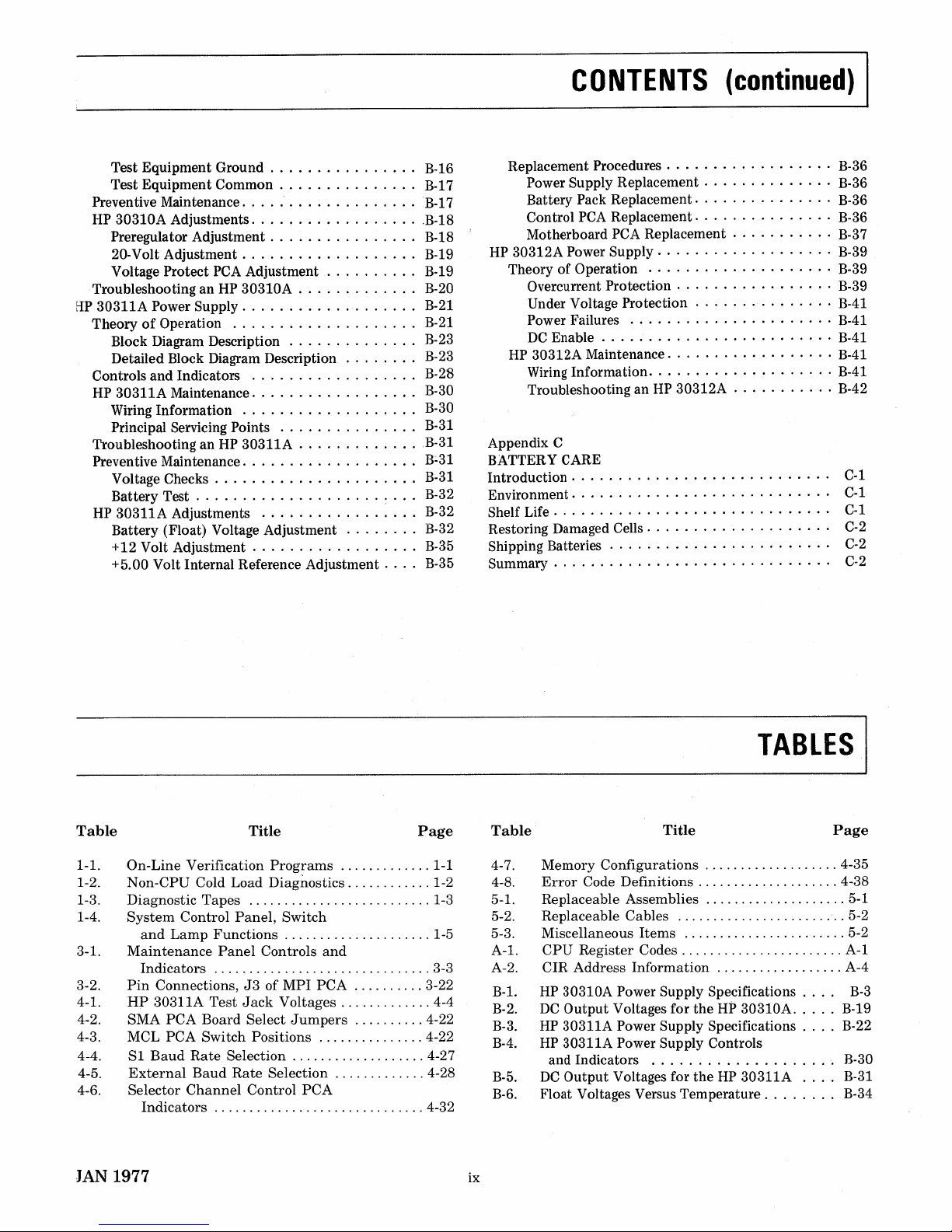
Test Equipment Ground B-16
Test Equipment Common B-17
Preventive Maintenance B-17
HP
30310A Adjustments B-18
Preregulator Adjustment B-18
20-Volt Adjustment . . . . . . . . . . . . . . . . .
..
B-19
Voltage Protect
PCA
Adjustment B-19
Troubleshooting an
HP
30310A . . . . . . . . . . . . . B-20
tIP
30311A Power
Supply.
. . . . . . . . . .... . . ...B-21
TheoryofOperation
B-21
Block Diagram Description . . . . . . . . . . . ...B-23
Detailed Block Diagram Description . . . . . ...B-23
Controls and Indicators B-28
HP
30311A Maintenance. . . . . . . . . . . . . . . ...B-30
Wiring Information B-30
Principal Servicing Points
B-31
Troubleshooting anHP30311A
B-31
Preventive Maintenance B:31
Voltage Checks
B-31
Battery Test
~
. . . B-32
HP
30311A Adjustments B-32
Battery (Float) Voltage Adjustment B-32
+12 Volt Adjustment B-35
+5.00 Volt Internal Reference Adjustment B-35
CONTENTS
(continued)
I
Replacement Procedures . . . . . . . . . . . . . . . . . . B-36
Power Supply Replacement B-36
Battery Pack Replacement. . . . . . . . . . . . . . . B-36
Control
PCA
Replacement B-36
Motherboard
PCA
Replacement B-37
HP
30312A Power Supply B-39
Theory of Operation B-39
Overcurrent Protection . . . . . . . . . . . . . . . . . B-39
Under Voltage Protection B-41
Power Failures B-41
DC
Enable . . . . . . . . . . . . . . . . . . . . . . . . .
B-41
HP
30312A Maintenance
B-41
Wiring Information B-41
Troubleshooting an
HP
30312A B-42
Appendix C
BATTERY CARE
Introduction . . . . . . . . . . . . . . . . . . . . . . . . . .
..
C-1
Environment. . . . . . . . . . . . . . . . . . . . . . . . . .
..
C-1
Shelf Life . . . . . . . . . . . . . . . . . . . . . . . . . . . .
..
C-1
Restoring Damaged Cells. . . . . . . . . . . . . . . . . .
..
C-2
Shipping Batteries . . . . . . . . . . . . . . . . . . . . . .
..
C-2
Summary . . . . . . . . . . . . . . . . . . . . . . . . . . . .
..
C-2
TABLES
I
Table
Title
Page
Table
Title
Page
1-1. On-Line Verification
Programs
1-1
1-2. Non-CPU Cold Load Diagnostics 1-2
1-3. Diagnostic Tapes 1-3
1-4.
System
Control
Panel,
Switch
and
Lamp
Functions
1-5
3-1.
Maintenance
Panel
Controls
and
Indi~ators
3-3
3-2.
Pin
Connections,J3of MPI
PCA
3-22
4-1.
HP
30311A
Test
Jack
Voltages 4-4
4-2. SMA
PCA
Board Select
Jumpers
4-22
4-3. MCL PCA Switch Positions 4-22
4-4.
SI
Baud
Rate
Selection 4-27
4-5.
External
Baud
Rate
Selection 4-28
4-6. Selector
Channel
Control
PCA
Indicators 4-32
JAN 1977
ix
4-7. Memory Configurations 4-35
4-8.
Error
Code Definitions 4-38
5-1. Replaceable Assemblies 5-1
5-2. Replaceable Cables 5-2
5-3. Miscellaneous Items 5-2
A-I.
CPU
Register
Codes
A-I
A-2. CIR Address Information A-4
B-l.
HP
30310A Power Supply Specifications. .
..
B-3
B-2.
DC
Output Voltages for
the
Hi>
30310A B-19
B-3.
HP
30311A Power Supply Specifications B-22
B-4.
HP
30311A Power Supply Controls
and Indicators B-30
B-5.
DC
Output Voltages for
theHP30311A B-31
B-6.
Float Voltages Versus Temperature B-34
Page 10
I
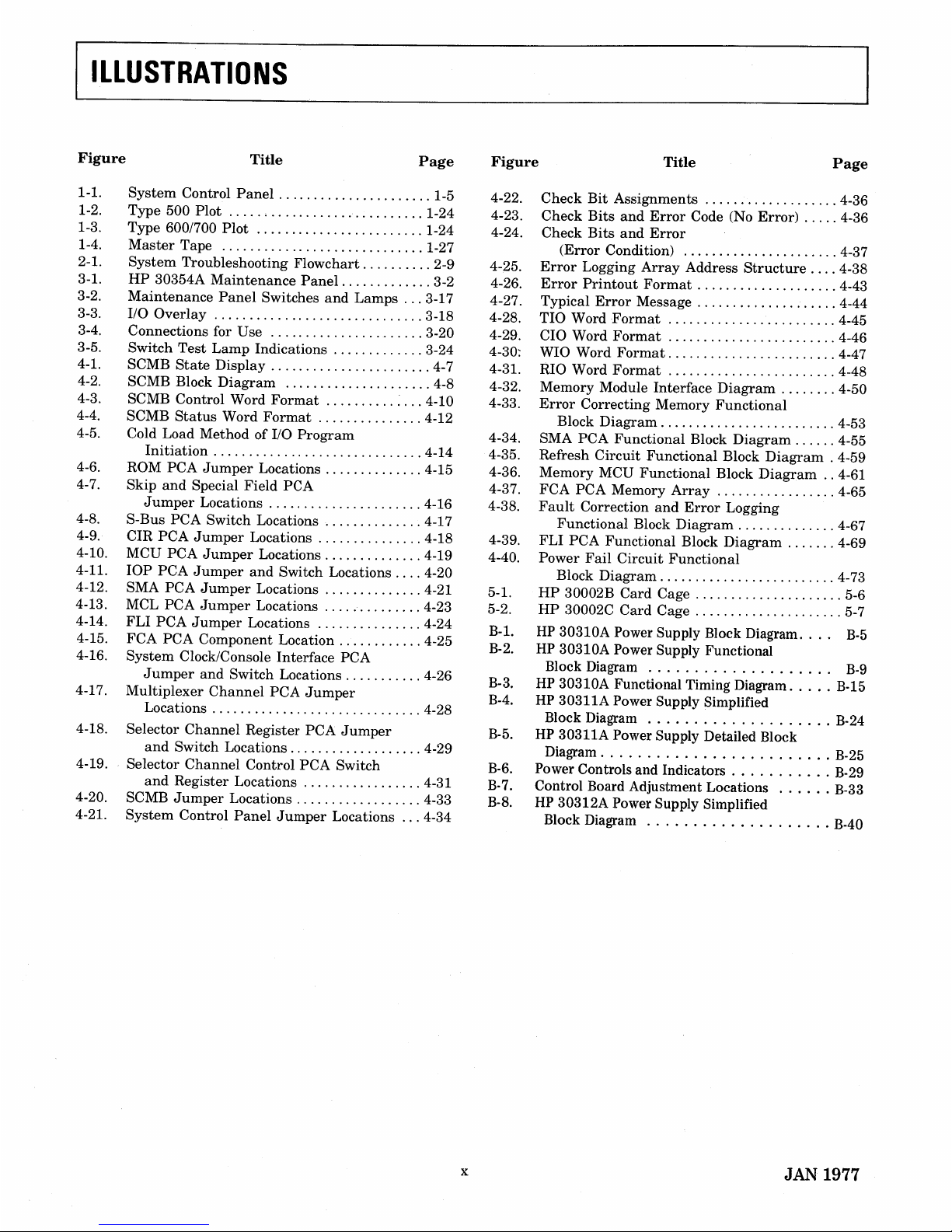
ILLUSTRATIONS
Figure
Title
Page
Figure
Title
Page
1-1.
1-2.
1-3.
1-4.
2-1.
3-1.
3-2.
3-3.
3-4.
3-5.
4-1.
4-2.
4-3.
4-4.
4-5.
4-6.
4-7.
4-8.
4-9.
4-10.
4-11.
4-12.
4-13.
4-14.
4-15.
4-16.
4-17.
4-18.
4-19.
4-20.
4-21.
System
Control
Panel
1-5
Type
500
Plot
1-24
Type
600/700
Plot
1-24
Master
Tape 1-27
System
Troubleshooting Flowchart 2-9
HP
30354A
Maintenance
Panel
3-2
Maintenance
Panel
Switches
and
Lamps
3-17
110
Overlay
3-18
Connections for Use 3-20
Switch
Test
Lamp
Indications 3-24
SCMB
State
Display 4-7
SCMB Block
Diagram
4-8
SCMB Control Word
Format
, ,..: 4-10
SCMB
Status
Word
Format
4-12
Cold Load Method
of
110
Program
Initiation
4-14
ROM
PCA
Jumper
Locations 4-15
Skip
and
Special
Field
peA
Jumper
Locations 4-16
S-Bus
PCA
Switch Locations 4-17
eIR
PCA
Jumper
Locations 4-18
MCU
PCA
Jumper
Locations 4-19
lOP
PCA
Jumper
and
Switch Locations 4-20
SMA
PCA
Jumper
Locations 4-21
MCL
PCA
Jumper
Locations 4-23
FLI
PCA
Jumper
Locations 4-24
FCA
PCA
Component Location 4-25
System
Clock/Console Interface
PCA
Jumper
and
Switch Locations 4-26
Multiplexer
Channel
PCA
Jumper
Locations 4-28
Selector
Channel
Register
PCA
Jumper
and
Switch Locations 4-29
Selector
Channel
Control
PCA
Switch
and
Register
Locations 4-31
SCMB
Jumper
Locations 4-33
System
Control
Panel
Jumper
Locations 4-34
x
4-22.
4-23.
4-24.
4-25.
4-26.
4-27.
4-28.
4-29.
4-30:
4-31.
4-32.
4-33.
4-34.
4-35.
4-36.
4-37.
4-38.
4-39.
4-40.
5-1.
5-2.
B-l.
B-2.
B-3.
B-4.
B-5.
B-6.
B-7.
B-8.
Check
Bit
Assignments
4-36
Check
Bits
and
Error
Code (No
Error)
4-36
Check
Bits
and
Error
(Error
Condition) 4-37
Error
Logging
Array
Address
Structure
4-38
Error
Printout
Format
4-43
Typical
Error
Message 4-44
TIO Word
Format
4-45
CIO Word
Format
4-46
WIO Word
Format
4-47
RIO Word
Format
4-48
Memory Module
Interface
Diagram
4-50
Error
Correcting
Memory
Functional
Block
Diagram
4-53
SMA
PCA
Functional
Block
Diagram
4-55
Refresh
Circuit
Functional
Block
Diagram
. 4-59
Memory MCU
Functional
Block
Diagram..4-61
FCA
PCA
Memory
Array
4-65
Fault
Correction
and
Error
Logging
Functional
Block
Diagram
4-67
FLI
PCA
Functional
Block
Diagram
4-69
Power
Fail
Circuit
Functional
Block
Diagram
4-73
HP
30002B
Card
Cage , 5-6
HP
30002C
Card
Cage 5-7
HP
30310A Power Supply Block Diagram. .
..
B-5
HP 30310A Power Supply Functional
Block Diagram
B-9
HP 30310A Functional Timing Diagram B-15
HP 30311A Power Supply Simplified
Block Diagram B-24
HP 30311A Power Supply Detailed Block
Diagram B-25
Power Controls and Indicators B-29
Control Board Adjustment Locations B-33
HP 30312A Power Supply Simplified
Block Diagram B-40
JAN 1977
Page 11
SYSTEM
VERIFICATION
I~
1-1. INTRODUCTION
This section contains verification procedures
that
are
extracts
from stand-alone diagnostics to provide
quick, easy to
run
diagnostics
that
verify system operation.
1-2. DIAGNOSTIC AND VERIFICATION PROGRAMS
The
HP
3000 Series II Computer System uses
three
types of
test
programs. They
are
ON-LINE
VERIFICATION PROGRAMS, STAND-ALONE DIAGNOSTICS,
and
MICRODIAGNOSTICS.
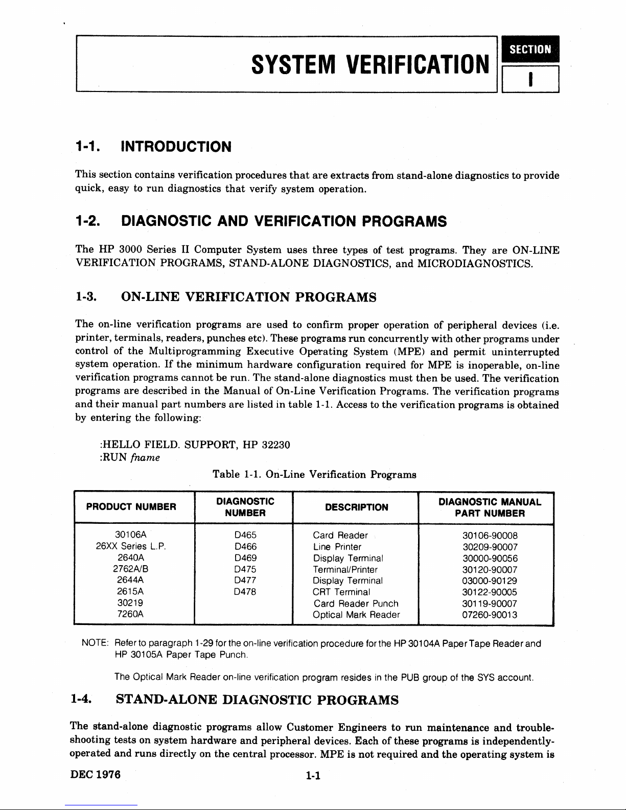
1-3. ON-LINE
VERIFICATION
PROGRAMS
The
on-line verification programs
are
used to confirm proper operationofperipheral
devices (i.e.
printer,
terminals,
readers, punches etc). These programs
run
concurrently
with
other
programs
under
controlofthe
Multiprogramming Executive Ope'tating System (MPE)
and
permit
uninterrupted
system operation.Ifthe
minimum
hardware
configuration required for MPE is inoperable, on-line
verification programs
cannot
be run. The stand-alone diagnostics
must
then
be used.
The
verification
programs
are
describedinthe
Manual
of On-Line Verification Programs. The verification
programs
and
their
manual
part
numbers
are
listed in
table
1-1. Access to
the
verification programs is obtained
by
entering
the
following:
:HELLO FIELD. SUPPORT,
HP
32230
:RUN
{name
Table 1-1. On-Line Verification Programs
PRODUCT NUMBER
DIAGNOSTIC
DESCRIPTION
DIAGNOSTIC MANUAL
NUMBER PART NUMBER
30106A
0465
Card Reader 30106-90008
26XX Series
L.P.
0466
Line Printer 30209-90007
2640A
0469
Display Terminal 30000-90056
2762A1B
0475
Terminal/Printer 30120-90007
2644A
0477
Display Terminal 03000-901
29
2615A
0478
CRT Terminal
30122-90005
30219
Card Reader Punch
30119-90007
7260A
Optical Mark Reader
07260-90013
NOTE: Refer to paragraph 1-29 for the on-line verification procedure forthe
HP
301
04A PaperTape Reader and
HP
30105A Paper Tape Punch.
The Optical Mark Reader on-line verification program resides
in
the
PUB
group of the
SYS
account.
1-4. STAND-ALONE DIAGNOSTIC
PROGRAMS
The stand-alone diagnostic programs allow Customer Engineerstorun
maintenance
and
trouble-
shooting tests on system
hardware
and
peripheral
devices.
Eachofthese
programs
is independently-
operated
and
runs
directly on
the
central
processor. MPE is
not
required
and
the
operating
system
is
DEC
1976
1-1
Page 12
I
System Service
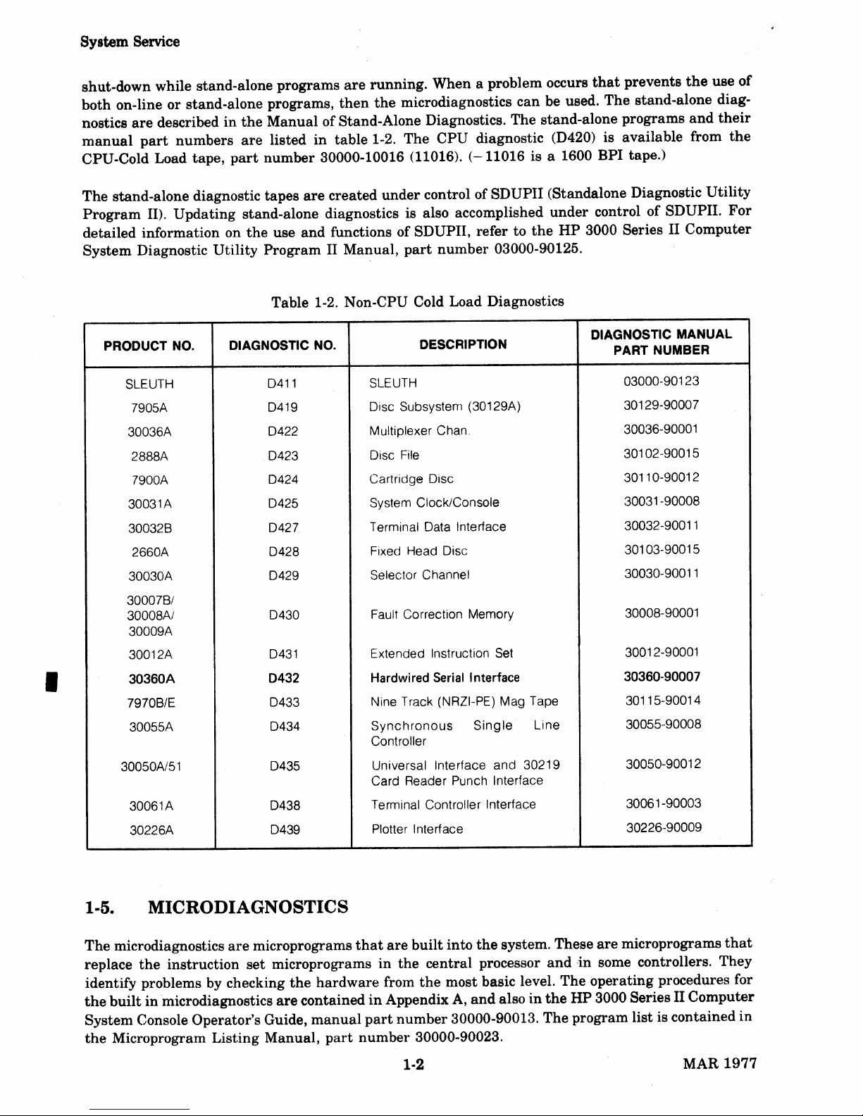
shut-down while stand-alone programs
are
running.
When a problem occurs
that
prevents
the
use
of
both on-lineorstand-alone programs,
then
the
microdiagnostics
can
be used.
The
stand-alone diag-
nostics
are
describedinthe
Manual
ofStand-Alone Diagnostics. The stand-alone programs
and
their
manual
part
numbers
are
listed
in
table
1-2. The
CPU
diagnostic (D420) is available from
the
CPU-Cold Load tape,
part
number
30000-10016 (11016).
(-11016
is a 1600 BPI tape.)
The
stand-alone diagnostic tapes
are
created
under
control of SDUPII (Standalone Diagnostic
Utility
Program
II). Updating stand-alone diagnostics is also accomplished
under
controlofSDUPII.
For
detailed information on
the
use
and
functions of SDUPII, refer to
the
HP
3000 Series II
Computer
System
Diagnostic
Utility
Program
II Manual,
part
number
03000-90125.
Table 1-2. Non-CPU Cold Load Diagnostics
PRODUCT NO.
DIAGNOSTIC NO. DESCRIPTION
DIAGNOSTIC
MANUAL
PART NUMBER
SLEUTH 0411
SLEUTH
03000-90123
7905A 0419
Oisc Subsystem (30129A)
30129-90007
30036A 0422 Multiplexer Chan 30036-90001
2888A
0423
Oisc
File
30102-90015
7900A 0424 Cartridge Oisc 30110-90012
30031A
0425
System Clock/Console
30031
-90008
300328 0427 Terminal
Oata
Interface 30032-90011
2660A
0428
Fixed Head Oisc 30103-90015
30030A 0429 Selector Channel 30030-90011
300078/
30008A/
0430 Fault Correction Memory
30008-90001
30009A
30012A 0431
Extended Instruction
Set
30012-90001
30360A
0432
Hardwired Serial Interface
30360-90007
79708/E 0433 Nine Track (NRZI-PE) Mag Tape
30115-90014
30055A
0434
Synchronous
Single
Line 30055-90008
Controller
30050A/51
0435 Universal Interface and 30219 30050-90012
Card Reader Punch Interface
30061
A
0438 Terminal Controller Interface 30061-90003
30226A
0439 Plotter Interface 30226-90009
1-5. MICRODIAGNOSTICS
The
microdiagnostics
are
microprograms
that
are
built
into
the
system. These
are
microprograms
that
replace
the
instruction
set
microprogramsinthe
central
processor
and
,in some controllers. They
identify problems by checking
the
hardware
from
the
most
basic level.
The
operating
procedures for
the
builtinmicrodiagnostics
are
containedinAppendixA,and
alsointhe
HP
3000 Series II
Computer
System
Console Operator's Guide,
manual
part
number
30000-90013.
The
program list is contained
in
the
Microprogram Listing Manual,
part
number
30000-90023.
1-2
MAR
1977
Page 13
System
Verification
1-6. PURPOSE
System
verification
procedures
are
usedtoverify
that
the
system
operates
correctly.
The
procedures
mayberun
afterarepair
has
been
made,
afterasystem
modificationorupdate
has
been
completed,
or
as a confidence
checkifsome
functional
areaofthe
systemissuspectedofa
malfunction.
SectionIIof
this
manual
contains
procedurestoisolateafault
to a
functional
area.
A
detected
malfunction
will
provide
an
error
message
that
canbeinterpreted
by
referring
to
the
specific
diagnostic
containedinthe
manualofstand-alone
diagnostics.
The
diagnostic
manuals
also
provide
detailed
operating
instructions
that
allow
additional
testing
and
analysistobe
performedona
suspected
subsystem.
1-7. FACILITIES REQUIRED
Table
1-3
lists
the
diagnostic
tapes
requiredtoperform
the
system
verification.
Table
1-2
lists
the
contentsofthe
Non-CPU
Cold
Load
diagnostic
tape.
This
table
lists
the
contents
ofamaximum
configured
system.
Consult
the
System
Configuration
Guide
shipped
with
the
systemtodetermine
the
specific
subsystems
availableata
particular
installation.
Diagnostics
on
the
tape
areinthe
order
listedinthe
table.
Table
1-1
lists
the
contentsofthe
on-line
diagnostic
tape.
Table
1-3.
Diagnostic
Tapes
TITLE
PART NUMBER
CPU-Cold Load
30000-10016/11016
Non CPU-Cold Load
30000-10017/11017
NOTE:
-11016
and
-11017
are 1600 bpi tapes.
1-8. SYSTEM VERIFICATION PROCEDURES
The
system
verification
procedures
contain
the
instructions
requiredtoexecute
the
diagnostic
pro-
grams.
Each
programisloaded
using
the
Cold Load
procedure.
The
verification
procedures
presented
in
this
section
were
preconfigured
using
SDUP.Ifa
diagnosticisrun
that
has
not
been
preconfigured,
operating
instructions
and
console
messages
will differ from
those
presented
in
this
section.
In
addition
to
the
verification
procedures
provided
in
this
section,
the
on-line
diagnostics
for
the
peripheral
equipment
should
alsobeexercised
for a
total
system
verification.
Refertothe
appropriate
on-line
diagnostic
manual
for
the
peripheralsinthe
system.
1-9.
SLEUTH
3000
SLEUTH
3000
is a
stand-alone
utility
writteninSPL/3000.Itis designedtogive service
personnel
the
capabilityofgenerating
unique
I/O
test
programs
that
run
under
the
controlofSLEUTH
3000.
These
programs
allow
isolation
of
I/O
problems
and
ease
the
troubleshooting
of
these
problems.
SLEUTH
3000
has
the
abilitytorun
uptofive
different
types
of
I/O
device
concurrently.Itcan
also
write
and
execute
SIO
programs,
store
and
restore
programs
on
magnetic
tape,
and
edit
the
programs.
Peripheral
devices
that
do
not
have on-line
and/or
stand-alone
verification
programs
require
that
SLEUTH
3000
programs
be
written
to
test
these
devices. Several
such
test
programs
have
been
written
for
specific
I/O
peripherals
(for
example,
the
SLEUTH07
program
describedinparagraph
1-32).
JAN
1977
1-3
Page 14
System
Service
SLEUTH
3000
will
runona
minimum
HP
3000
Series
II.
Refertothe
HP
ManualofDiagnostics
for
complete
information
on
the
useofSLEUTH
3000
I/O
Diagnostic
D411,
manual
part
number
03000-90123.
1-10.
SYSTEM CONTROL
PANEL
The
system
control
panel
locatedatthe
top
frontofequipment
bay1provides
the
system
operator
and
service
personnel
the
controls
and
lampstoperform
the
following functions:
• cold
load
and
run
diagnostics
•
load
and
run
user
programs
•
halt
programs
•
system
dump
• observe
the
current
instruction
register
•
reset
the
CPU
•
enableordisable
the
auto
restart
function
afterapower
failure
All
switches
locatedonthe
frontofthe
control
panel
are
three-position
spring-return
rocker
switches.
These
switches
have
a center-off position.
They
are
pressedonthe
toporbottom
halftoproduce
the
desired
function.
When
released,
they
returntothe
center
position.
Located
behind
the
upper
right
portionofthe
panel
are
three
switches
accessible
when
the
cabinet
door is opened:
CPU
RESET-A
two-position
spring-return
switch
usedtoreset
the
circuitsofthe
CPU.
PANEL
DISABLE/ENABLE-A
two
position
switch
that
enablesordisables
the
system
panel
for
use.
PF/ARS
DISABLE
ENABLE-A
two
position
switchtoenableordisable
the
auto
restart
program
in
the
eventofa
power
failure.
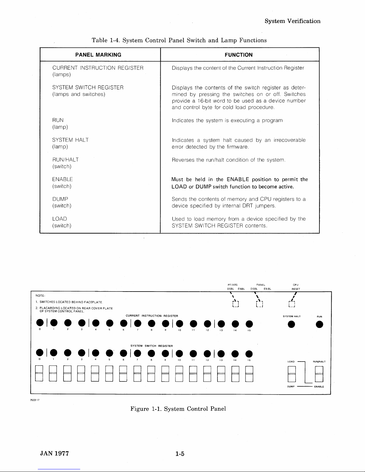
Table
1-4
lists
and
explains
the
functionofthe
switches
and
lamps
that
are
illustratedinfigure
1-1.
1-11. MAINTENANCE
PANEL
The
HP
30354A
Maintenance
Panel
canbeusedtoperform
the
functionsofSystem
Control
Panel.
In
addition,
the
maintenance
panel
can
assistinlocalizing
faults,
show
the
contentsofselected
registers
and
the
stateofmajor
signals,
and
modify
the
contentsofselected
registers.
The
function
and
use
of
the
panel
is describedinSection
IIIofthis
manual.
1-4
JAN
1977
Page 15
System
Verification
Table 1-4. System Control Panel Switch and Lamp Functions
PANEL MARKING
CURRENT INSTRUCTION REGISTER
(lamps)
SYSTEM SWITCH REGISTER
(lamps and switches)
RUN
(lamp)
SYSTEM HALT
(lamp)
RUN/HALT
(switch)
ENABLE
(switch)
DUMP
(switch)
LOAD
(switch)
FUNCTION
Displays the content of the Current Instruction Register
Displays the contents
of
the switch register as deter-
mined
by
pressing the switches onoroff. Switches
provide a 16-bit word to be used as a
device
number
and control byte for
cold
load procedure.
Indicates the system is executing a program
Indicates a system halt
caused
by an irrecoverable
error
detected
by the firmware.
Reverses the run/halt condition of the system.
Mustbeheldinthe
ENABLE
position to permit the
LOADorDUMP
switch function to become active.
Sends the contents of memory and CPU registers to a
device
specified by internal DRT jumpers.
Used to load memory from a
device
specified by the
SYSTEM SWITCH REGISTER contents.
NOTE:
1.
SWITCHES LOCATED BEHIND FACEPLATE
2.
PLACARDING
LOCATEDONREAR COVER
PLATE
OF
SYSTEM
CONTROL
PANEL
PF/ARS
PANEL
DSBL
ENBL
DSBLENBL
,
,
\
\
...
\,
...
\,
L_J
L
_J
CPU
RESET
CURRENT
INSTRUCTION
REGISTER
ele
e
ele
e
ele
e
ele
e
ele
e e
o 1 2 3 4 5 6 7 8 9
13
SYSTEM
SWITCH
REGISTER
SYSTEM
HALT
RUN
ele
e
ele
e-
ele
e
ele
e
ele
e e
o 1 2 3 4 5 6 7 8 9
10
11
13
14
BBBBBBBBBBBBBBBB
DUMP
--
ENABLE
7522-17
Figure 1-1.
System
Control Panel
JAN
1977
1-5
Page 16
System
Service
1-12. COLD LOAD (DIAGNOSTIC)
Perform
the
following
steps
to cold load a
diagnostic
tape.
NOTE
When
the
SYSTEM
SWITCH
REGISTER
bit
8 is
set
to 0,
all
memoryisinitialized
withaHALT
%10
instruction
(%030370)
priortoexecuting
the
cold load.Ifbit
8 is
setto1, no
initialization
occurs
priortothe
cold load.
a.
Load
tape
on
tape
unit
O.
b..Enter
%003006 on SYSTEM
SWITCH
REGISTER.
Simultaneously
press
LOAD
and
ENABLE
switches.
c.
Select
the
appropriate
diagnostic
file
number
from
the
tape
and
enter
this
octal
number
in
the
SYSTEM
SWITCH
REGISTER.
d.
Press
RUN.
The
diagnostic
loads
and
the
tape
rewindsatthe
endofthe
load.
e.
Set
SYSTEM
SWITCH
REGISTER
to 000000.
NOTE
The
following
verification
procedures
can
onlybeused
with
tapes
shipped
with
the
system
and
listedinTable
1-2.
Unless
directed
otherwise,
all
operator
entries
are
made
using
the
system
console.
NOTE
Priortoperforming
any
maintenance
or
shutdown
procedures,
have
the
System
Operator
verify
that
all
jobs/sessions
have
been
termina
ted
before proceeding.
NOTE
Do
not
power-uporpower-down
any
peripheral
device
when
a
diagnosticisrunning.
Failure
to observe
this
note
could
adversely
effect
the
diagnostic
thatisexecuting.
1-13.
HP
30129 CARTRIDGE DISC DIAGNOSTIC (D419)
The
diagnostic
verifies
the
input,
output,
and
control
functionsofthe
HP
30129A
Cartridge
Disc
subsystem.
The
following
procedureisusedtoverify
operation.
NOTE
A
SYSDUMP
should
be
performed
priortoexecuting
the
diag-
nostic.ARELOAD
must
be
performed
after
completing
the
diagnostic.
1-6
Page 17
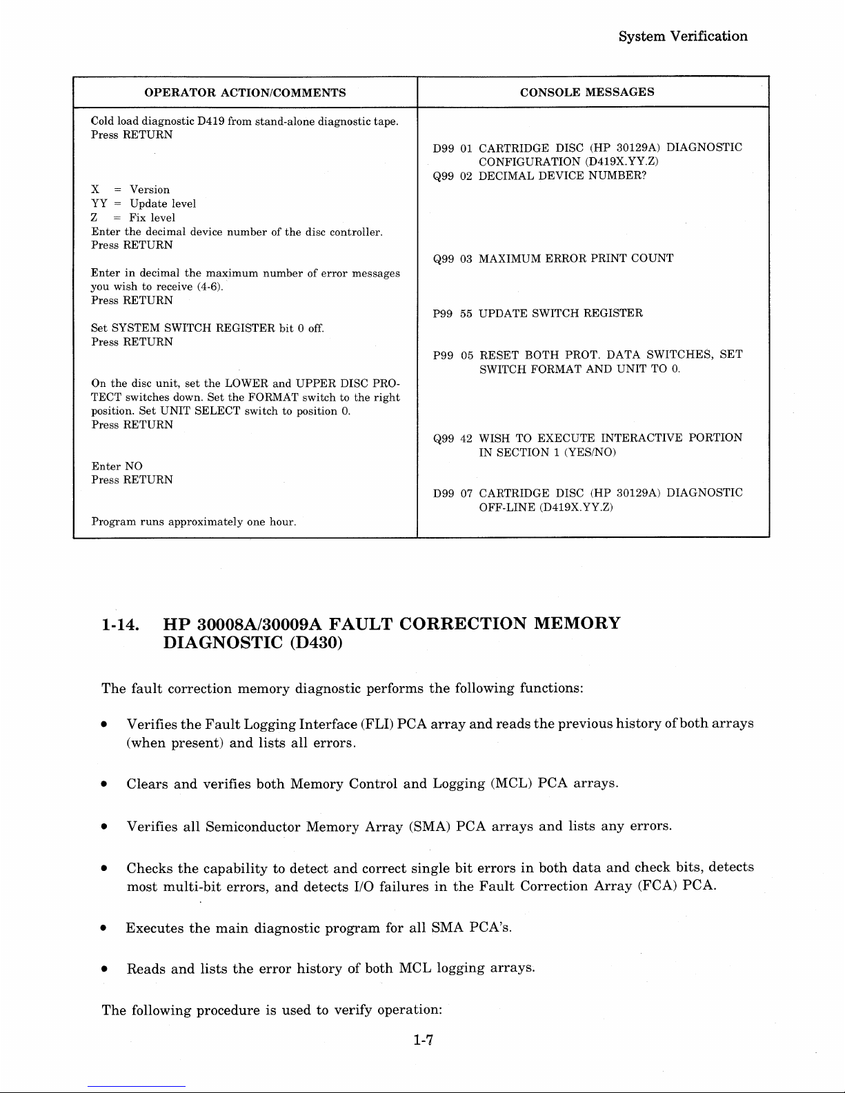
OPERATOR
ACTION/COMMENTS
Cold load diagnostic D419 from
stand-alone
diagnostic tape.
Press
RETURN
x = Version
YY
=
Update
level
Z
= Fix level
Enter
the
decimal device
numberofthe
disc controller.
Press
RETURN
Enterindecimal
the
maximum
numberoferror
messages
you
wish to receive (4-6).
Press
RETURN
Set
SYSTEM SWITCH REGISTER
bit0off.
Press
RETURN
On
the
disc
unit,
set
the
LOWER
and
UPPER
DISC PRO-
TECT switches down.
Set
the
FORMAT switch to
the
right
position.
Set
UNIT
SELECT
switch to position
O.
Press
RETURN
Enter
NO
Press
RETURN
Program
runs
approximately
one hour.
System
Verification
CONSOLE
MESSAGES
D99 01 CARTRIDGE DISC (HP 30129A) DIAGNOSTIC
CONFIGURATION (D419X.YY.Z)
Q99 02 DECIMAL DEVICE NUMBER?
Q99 03 MAXIMUM ERROR
PRINT
COUNT
P99
55 UPDATE SWITCH REGISTER
P9905RESET
BOTH
PROT. DATA
SWITCHES,
SET
SWITCH FORMAT AND
UNIT
TO
O.
Q99 42 WISH TO
EXECUTE
INTERACTIVE PORTION
IN
SECTION
1 (YES/NO)
D99 07 CARTRIDGE DISC
(HP
30129A) DIAGNOSTIC
OFF-LINE
(D419X.YY.Z)
1-14.
HP
30008A/30009A
FAULT
CORRECTION
MEMORY
DIAGNOSTIC
(D430)
The
fault
correction
memory
diagnostic
performs
the
following functions:
• Verifies
the
Fault
Logging
Interface
(FLI)
PCA
array
and
reads
the
previous
historyofboth
arrays
(when
present)
and
lists
all
errors.
•
Clears
and
verifies
both
Memory
Control
and
Logging
(MCL)
PCA
arrays.
•
Verifies
all
Semiconductor
Memory
Array
(SMA)
PCA
arrays
and
lists
any
errors.
•
Checks
the
capabilitytodetect
and
correct
single
bit
errorsinboth
data
and
check
bits,
detects
most
multi-bit
errors,
and
detects
I/O
failuresinthe
Fault
Correction
Array
(FCA)
PCA.
•
Executes
the
main
diagnostic
program
for
all
SMA PCA's.
•
Reads
and
lists
the
error
historyofboth
MCL
logging
arrays.
The
following
procedureisusedtoverify
operation:
1-7
Page 18
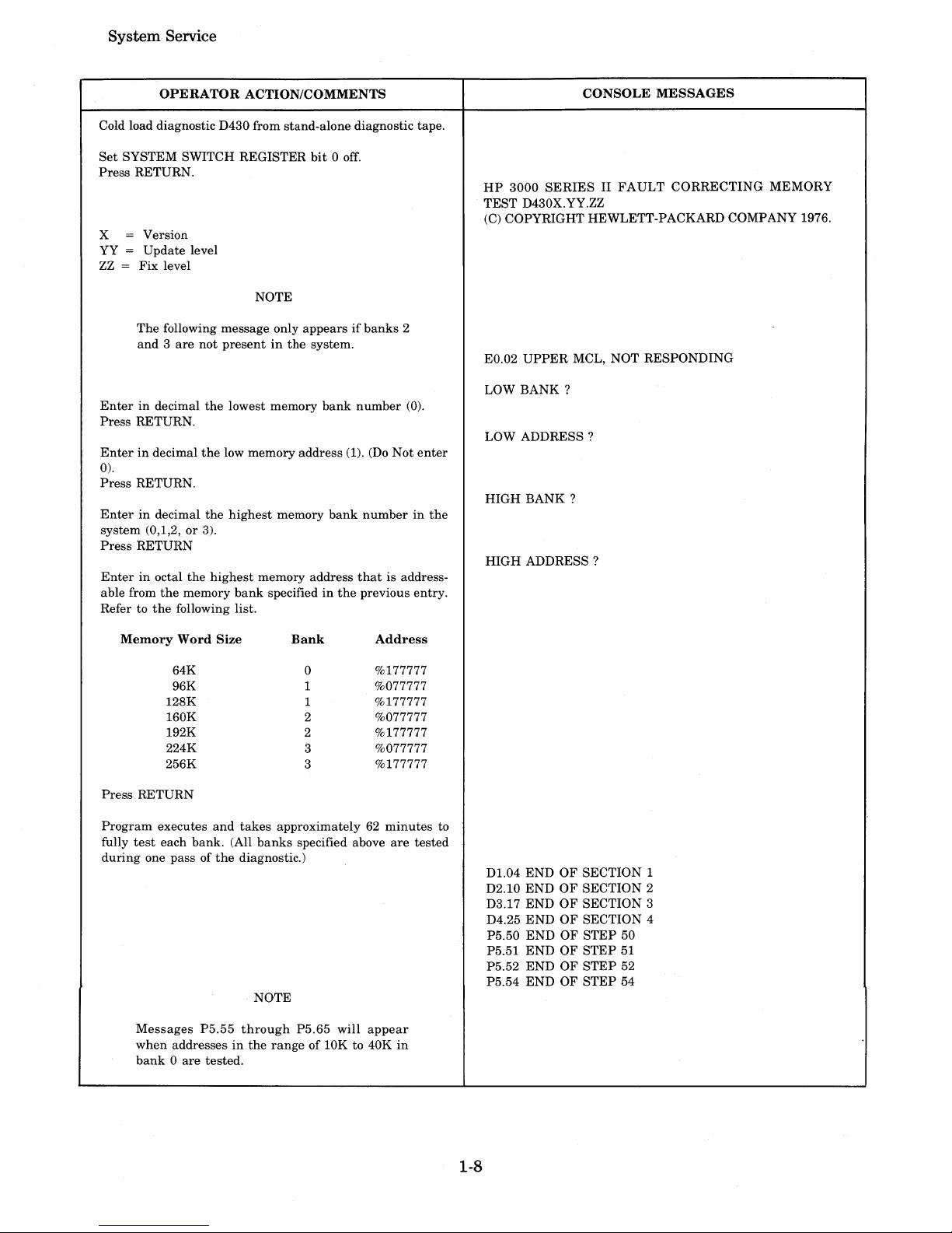
System·Service
OPERATOR
ACTION/COMMENTS
Cold load diagnostic D430 from stand-alone diagnostic tape.
Set
SYSTEM SWITCH REGISTER
bit
0 off.
Press
RETURN.
x = Version
YY
=
Update
level
ZZ
= Fix level
NOTE
The
following message only
appearsifbanks
2
and3are
not
presentinthe
system.
Enterindecimal
the
lowest
memory
bank
number
(0).
Press
RETURN.
Enterindecimal
the
low
memory
address
(1). (Do
Not
enter
0).
Press
RETURN.
Enterindecimal
the
highest
memory
bank
numberinthe
system
(0,1,2,or3).
Press
RETURN
Enterinoctal
the
highest
memory
address
that
is address-
able from
the
memory
bank
specifiedinthe
previous
entry.
Refer to
the
following list.
Memory
Word
Size
Bank
Address
64K
0
%177777
96K 1
%077777
128K
1
%177777
160K 2
%077777
192K
2
%177777
224K
3
%077777
256K
3
%177777
Press
RETURN
Program
executes
and
takes
approximately62minutes
to
fully
test
each
bank.
(All
banks
specified above
are
tested
during
one pass of
the
diagnostic.)
NOTE
Messages
P5.55
through
P5.65
will
appear
when
addressesinthe
rangeof10K to 40K
in
bank0are
tested.
1-8
CONSOLE
MESSAGES
HP
3000
SERIESIIFAULT
CORRECTING
MEMORY
TEST
D430X.YY.ZZ
(C)
COPYRIGHT HEWLETT-PACKARD COMPANY 1976.
EO.02
UPPER
MCL, NOT
RESPONDING
LOW
BANK?
LOW
ADDRESS?
HIGH
BANK?
HIGH
ADDRESS?
D1.04 ENDOFSECTION
1
D2.10 END
OF
SECTION
2
D3.17
ENDOFSECTION 3
D4.25
ENDOFSECTION 4
P5.50
ENDOFSTEP
50
P5.51
ENDOFSTEP
51
P5.52
ENDOFSTEP
52
P5.54
ENDOFSTEP
54
Page 19
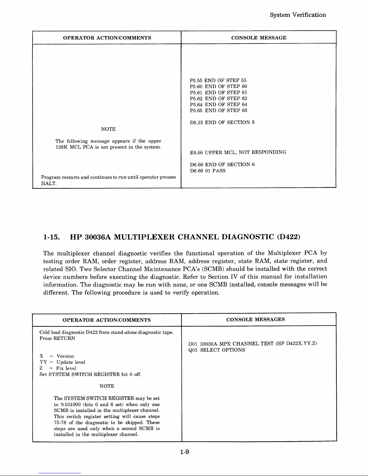
System
Verification
OPERATOR
ACTION/COMMENTS
CONSOLE
MESSAGE
P5.55
ENDOFSTEP
55
P5.60
ENDOFSTEP
60
P5.61
ENDOFSTEP
61
P5.62
ENDOFSTEP
62
P5.64
ENDOFSTEP
64
P5.65
ENDOFSTEP
65
D5.25
ENDOFSECTION
5
NOTE
The
following
message
appearsifthe
upper
128K MCL PCA is
not
presentinthe
system.
E6.66
UPPER
MCL, NOT
RESPONDING
D6.66
ENDOFSECTION
6
D6.66 01 PASS
Program
restarts
and
continuestorun
until
operator
presses
HALT.
1-15.
HP
30036A
MULTIPLEXER
CHANNEL
DIAGNOSTIC
(D422)
The
multiplexer
channel
diagnostic
verifies
the
functional
operationofthe
Multiplexer
PCA
by
testing
order
RAM,
order
register,
address
RAM,
address
register,
state
RAM,
state
register,
and
related
SIO. Two
Selector
Channel
Maintenance
PCA's
(SCMB)
shouldbeinstalled
with
the
correct
device
numbers
before
executing
the
diagnostic.
Refer
to SectionIVof
this
manual
for
installation
information.
The
diagnostic
mayberun
with
none,orone SCMB
installed,
console
messages
will
be
different.
The
following
procedureisusedtoverify
operation.
OPERATOR
ACTION/COMMENTS
CONSOLE
MESSAGES
Cold load diagnostic D422 from
stand-alone
diagnostic tape.
Press
RETURN
DOl 30036A MPX
CHANNEL
TEST
(HP D422X.YY.Z)
Q01 SELECT
OPTIONS
X
=
Version
YY
=
Update
level
Z
=
Fix
level
Set
SYSTEM SWITCH REGISTER
bit
0 off.
NOTE
The
SYSTEM SWITCH REGISTER
maybeset
to %101000 (bits 0
and
6 set)
when
only one
SCMB is
installedinthe
multiplexer
channel.
This
switch
register
setting
will
cause
steps
75-78ofthe
diagnostic to be skipped. These
steps
are
used only
when
a second SCMB
is
installedinthe
multiplexer
channel.
1-9
Page 20
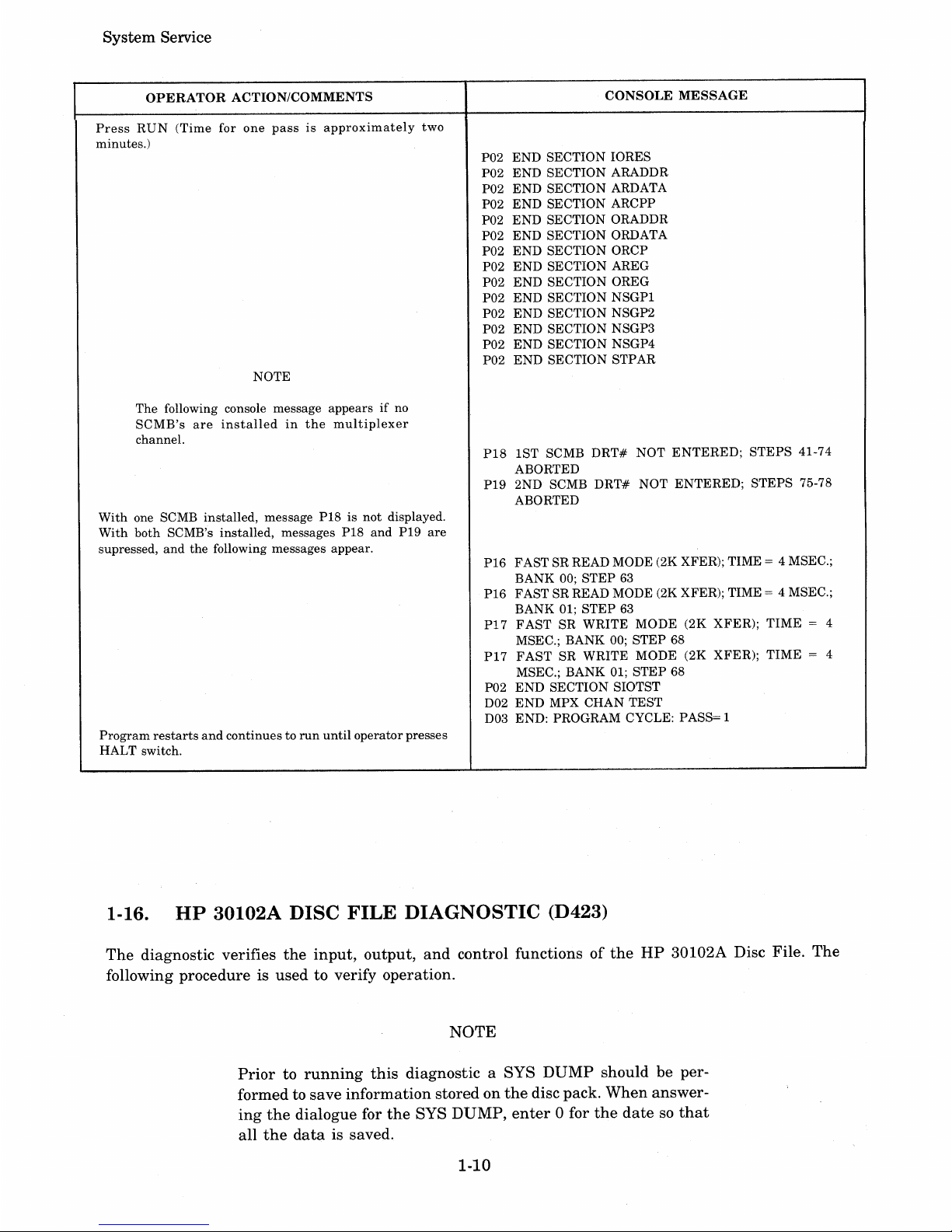
System
Service
OPERATOR
ACTION/COMMENTS
Press
RUN
(Time
for
one
passisapproximately
two
minutes.)
NOTE
The following console message appears
if
no
SCMB's
are
installed
in
the
multiplexer
channel.
With
one SCMB installed, message P18 is
not
displayed.
With
both SCMB's installed, messages P18
and
P19
are
supressed,
and
the
following messages appear.
Program
restarts
and
continues to
run
until
operatorpresses
HALT switch.
CONSOLE
MESSAGE
P02
END
SECTION IORES
P02 END SECTION ARADDR
P02
END
SECTION ARDATA
P02
END
SECTION ARCPP
P02
END
SECTION ORADDR
P02 END SECTION ORDATA
P02
END
SECTION ORCP
P02
END
SECTION AREG
P02
END
SECTION OREG
P02
END
SECTION
NSGPI
P02
END
SECTION NSGP2
P02
END
SECTION NSGP3
P02
END
SECTION NSGP4
P02
END
SECTION STPAR
P18
1ST SCMB
DRT#
NOT
ENTERED;
STEPS
41-74
ABORTED
P19 2ND SCMB
DRT#
NOT
ENTERED;
STEPS
75-78
ABORTED
P16 FAST SR READ MODE (2K XFER); TIME = 4 MSEC.;
BANK 00;
STEP
63
P16 FAST SR READ MODE (2K XFER); TIME = 4 MSEC.;
BANK 01;
STEP
63
PI7
FAST
SR
WRITE
MODE
(2K XFER);
TIME
= 4
MSEC.; BANK 00;
STEP
68
P17
FAST
SR
WRITE
MODE (2K XFER);
TIME
= 4
MSEC.; BANK 01;
STEP
68
P02
END
SECTION SIOTST
D02
END
MPX CHAN
TEST
D03 END: PROGRAM CYCLE: PASS= 1
1..16.
HP
30102A DISC FILE DIAGNOSTIC (D423)
The
diagnostic verifies
the
input,
output,
and
control functionsofthe
HP
30102A Disc File.
The
following procedure is
used
to verify operation.
NOTE
Priortorunning
this
diagnostic a SYS
DUMP
should
be per-
formed to
save
information
storedonthe
disc pack.
When
answer-
ing
the
dialogue for
the
SYS
DUMP,
enter
0 for
the
datesothat
all
the
data
is saved.
1-10
Page 21
OPERATOR
ACTION/COMMENTS
Cold load
diagnostic
D423 from
stand-alone
diagnostic
tape.
Press
RETURN
x =
Version
YY =
Update
level
Z
=
Fix
level
Enterindecimal
the
DRT
numberofthe
disc controller.
Press
RETURN
Enter
ON
Press
RETURN
(The
message
means
the
hardware
has
paused
(%030040
in
CIR)
andiswaiting
foranupdateofthe
switch
register.)
Set
SYSTEM SWITCH
REGISTER
bit
0 off.
Press
RETURN
Program
runs
approximately
one
hour
to completion.
System Verification
CONSOLE
MESSAGES
D99 01 DISC
FILE
(30102A) DIAG
CONFG
(D423X.YY.Z)
Q99 02 DECIMAL
DEVICE
NUMBER
Q99 03
INTERRUPTSONOR
OFF?
P99 61
PAUSE
AFTER
CONFIGURATION
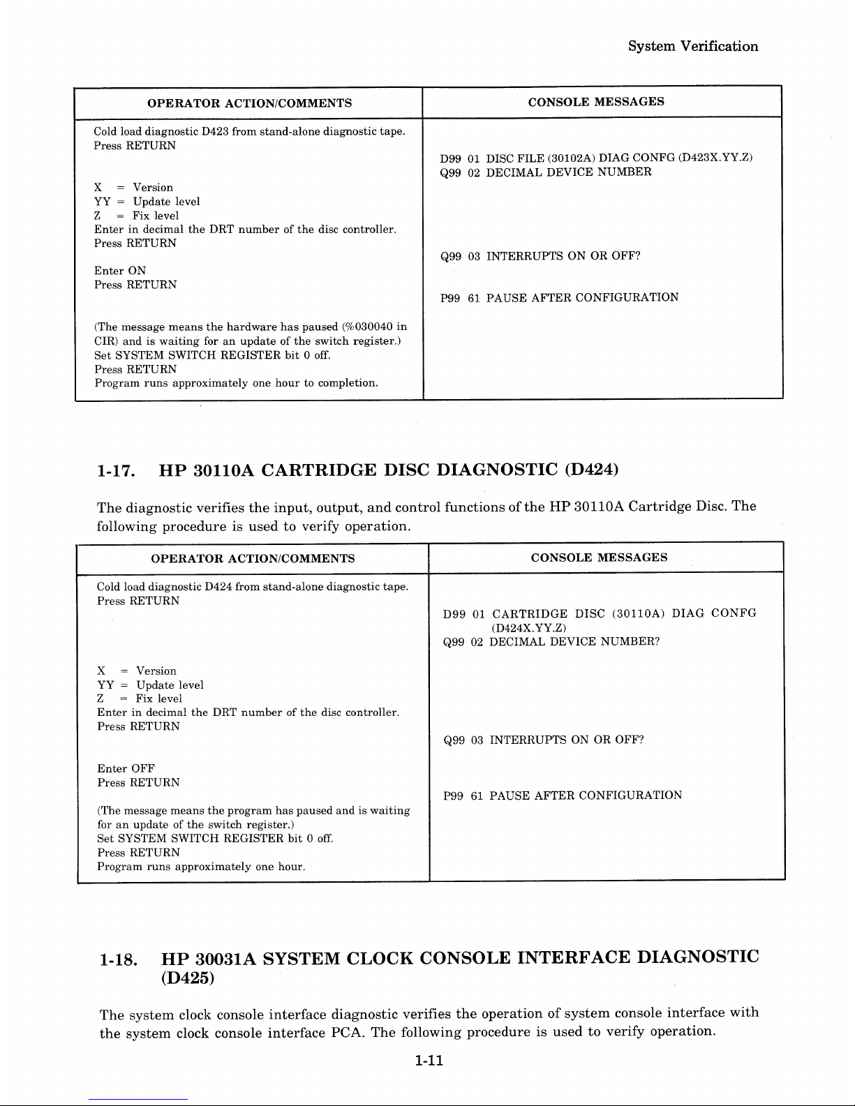
1-17.
HP
30110A
CARTRIDGE
DISC
DIAGNOSTIC
(D424)
The
diagnostic
verifies
the
input,
output,and
control
functionsofthe
HP
30110A
Cartridge
Disc.
The
following
procedureisusedtoverify
operation.
OPERATOR
ACTION/COMMENTS
Cold load
diagnostic
D424 from
stand-alone
diagnostic
tape.
Press
RETURN
x =
Version
YY =
Update
level
Z
=
Fix
level
Enterindecimal
the
DRT
numberofthe
disc controller.
Press
RETURN
Enter
OFF
Press
RETURN
(The
message
means
the
program
has
paused
andiswaiting
foranupdateofthe
switch
register.)
Set
SYSTEM
SWITCH
REGISTER
bit0off.
Press
RETURN
Program
runs
approximately
one
hour.
CONSOLE
MESSAGES
D99
01
CARTRIDGE
DISC
(30110A)
DIAG
CONFG
(D424X. YY.Z)
Q99 02 DECIMAL
DEVICE
NUMBER?
Q99 03
INTERRUPTSONOR
OFF?
P9961PAUSE
AFTER
CONFIGURATION
1-18.
HP
30031A
SYSTEM
CLOCK
CONSOLE
INTERFACE
DIAGNOSTIC
(D425)
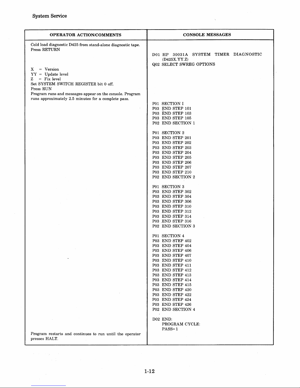
The
system
clock console
interface
diagnostic
verifies
the
operationofsystem
console
interface
with
the
system
clock console
interface
PCA.
The
following
procedureisusedtoverify
operation.
1-11
Page 22
System Service
OPERATOR ACTION/COMMENTS
Cold load diagnostic D425 from stand-alone diagnostic tape.
Press
RETURN
x = Version
YY =
Update
level
Z =
Fix
level
Set
SYSTEM SWITCH REGISTER
bit0off.
Press
RUN
Program
runs
and
messages
appearonthe
console.
Program
runs
approximately 2.5
minutes
for a complete pass.
Program·
restarts
and
continues to
run
until
the
operator
presses HALT.
CONSOLE MESSAGES
DOl
HP
3003lA
SYSTEM
TIMER
DIAGNOSTIC
(D425X.YY.Z)
Q02 SELECT SWREG OPTIONS
POI SECTION I
P03
~ND
STEP
101
P03 END
STEP
103
P03
END
STEP
105
P02
END
SECTION 1
POI SECTION 2
P03
END
STEP
201
P03
END
STEP
202
P03
END
STEP
203
P03
END
STEP
204
P03
END
STEP
205
P03
END
STEP
206
P03
END
STEP
207
P03
END
STEP
210
P02
END
SECTION 2
POI SECTION 3
P03
END
STEP
302
P03 END
STEP
304
P03
END
STEP
306
P03
END
STEP
310
P03
END
STEP
312
P03
END
STEP
314
P03 .END
STEP
316
P02
END
SECTION 3
POI SECTION 4
P03
END
STEP
402
P03
END
STEP
404
P03
END
STEP
406
P03
END
STEP
407
P03
END
STEP
410
P03
END
STEP
411
P03 END
STEP
412
P03
END
STEP
413
P03
END
STEP
414
P03
END
STEP
415
P03
END
STEP
420
P03
END
STEP
422
P03
END
STEP
424
P03
END
STEP
426
P02
END
SECTION 4
D02 END:
PROGRAM CYCLE:
PASS=l
1-12
Page 23
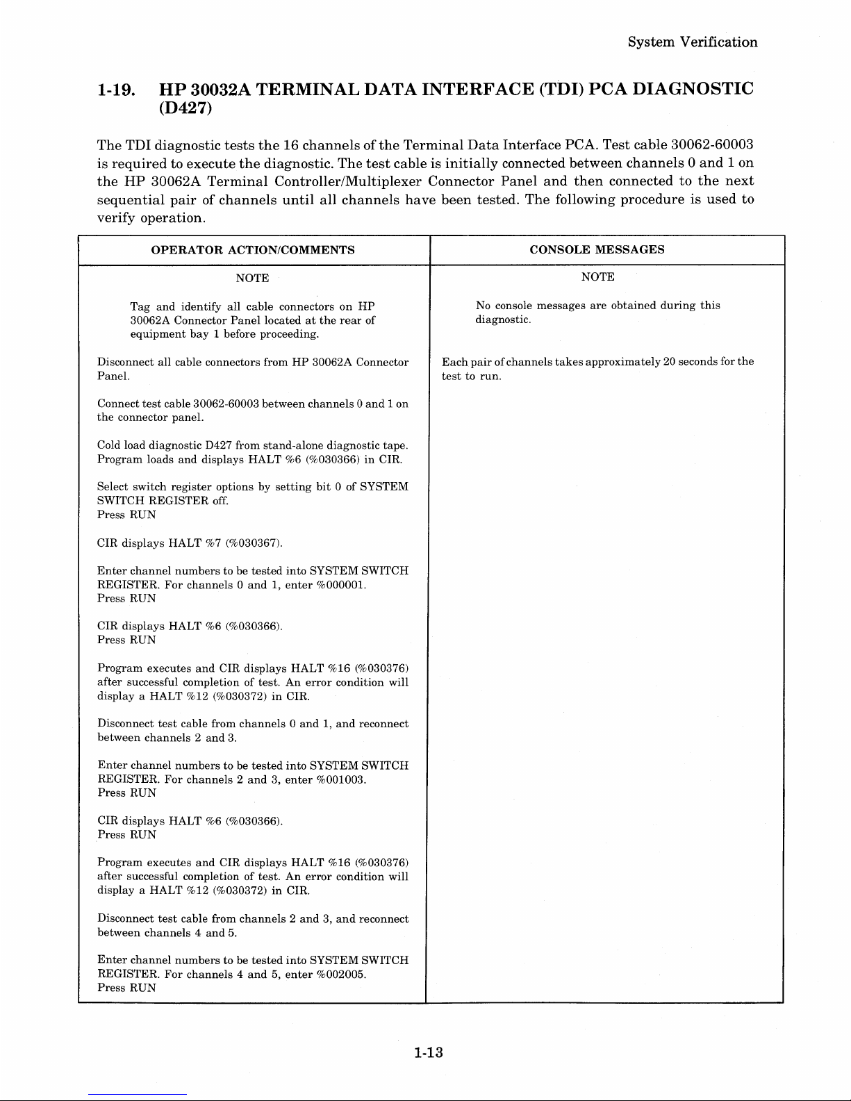
1-19.
System
Verification
HP
30032A TERMINAL
DATA
INTERFACE
(TDI)
peA
DIAGNOSTIC
(D427)
The
TDI
diagnostic
tests
the16channelsofthe
Terminal
Data
Interface
PCA.
Test
cable
30062-60003
is
requiredtoexecute
the
diagnostic.
The
test
cable is
initially
connected
between
channels0and1on
the
HP
30062A
Terminal
Controller/Multiplexer
Connector
Panel
and
then
connectedtothe
next
sequential
pairofchannels
until
all
channels
have
been
tested.
The
following
procedureisused
to
verify
operation.
OPERATOR
ACTION/COMMENTS
CONSOLE
MESSAGES
NOTE
NOTE
Tag
and
identify
all
cable
connectorsonHP
No console
messages
are
obtained
during
this
30062A
Connector
Panel
locatedatthe
rear
of
diagnostic.
equipment
bay
1 before proceeding.
Disconnect
all
cable connectors
fromHP30062A
Connector
Each
pairofchannels
takes
approximately
20 seconds for
the
Panel.
testtorun.
Connect
test
cable 30062-60003
between
channels0and1on
the
connector
panel.
Cold load
diagnostic
D427 from
stand-alone
diagnostic
tape.
Program
loads
and
displays
HALT
%6 (%030366)inCIR.
Select
switch
register
optionsbysetting
bit0of
SYSTEM
SWITCH
REGISTER
off.
Press
RUN
CIR
displays
HALT
%7 (%030367).
Enter
channel
numbers
to be
tested
into
SYSTEM
SWITCH
REGISTER.
For
channels0and1,enter
%000001.
Press
RUN
CIR
displays
HALT
%6 (%030366).
Press
RUN
Program
executes
and
CIR
displays
HALT
%16 (%030376)
after
successful completionoftest.Anerror
condition
will
displayaHALT
%12 (%030372)inCIR.
Disconnect
test
cable
from
channels0and1,and
reconnect
between
channels2and
3.
Enter
channel
numberstobe
tested
into
SYSTEM
SWITCH
REGISTER.
For
channels2and3,enter
%001003.
Press
RUN
CIR
displays
HALT
%6 (%030366).
Press
RUN
Program
executes
and
CIR
displays
HALT
%16 (%030376)
after
successful completionoftest.Anerror
condition
will
displayaHALT
%12 (%030372)inCIR.
Disconnect
test
cable from
channels2and3,and
reconnect
between
channels4and
5.
Enter
channel
numberstobe
tested
into
SYSTEM
SWITCH
REGISTER.
For
channels4and5,enter
%002005.
Press
RUN
1-13
Page 24
System
Service
OPERATOR
ACTION/COMMENTS
CONSOLE
MESSAGE
CIR
displays
HALT
%6 (%030366).
Press
RUN
Program
executes
and
CIR
displays
HALT
%16 (%030376)
after
successful
completionoftest.Anerror
condition
will
displayaHALT
%12 (%030372)inCIR.
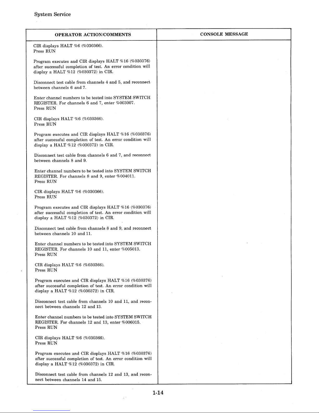
Disconnect
test
cable
from
channels4and5,and
reconnect
between
channels6and
7.
Enter
channel
numbers
to be
tested
into
SYSTEM
SWITCH
REGISTER.
For
channels6and7,enter
%003007.
Press
RUN
CIR
displays
HALT
%6 (%030366).
Press
RUN
Program
executes
and
CIR
displays
HALT
%16 (%030376)
after
successful
completionoftest.Anerror
condition
will
displayaHALT
%12 (%030372)inCIR.
Disconnect
test
cable
from
channels6and7,and
reconnect
between
channels8and
9.
Enter
channel
numbers
to be
tested
into
SYSTEM
SWITCH
REGISTER.
For
channels8and9,enter
%00401L
Press
RUN
CIR
displays
HALT
%6 (%030366).
Press
RUN
Program
executes
and
CIR
displays
HALT
%16 (%030376)
after
successful
completionoftest.Anerror
condition
will
displayaHALT
%12 (%030372)inCIR.
Disconnect
test
cable from
channels8and9,and
reconnect
between
channels10and
II.
Enter
channel
numberstobe
tested
into
SYSTEM
SWITCH
REGISTER.
For
channels10and
11,
enter
%005013.
Press
RUN
CIR
displays
HALT
%6 (%030366).
Press
RUN
Program
executes
and
CIR
displays
HALT
%16 (%030376)
after
successful
completionoftest.Anerror
condition
will
displayaHALT
%12 (%030372)inCIR.
Disconnect
test
cable
from
channels10and
11,
and
recon-
nect
between
channels12and
13.
Enter
channel
numberstobe
tested
into
SYSTEM
SWITCH
REGISTER.
For
channels12and
13,
enter
%006015.
Press
RUN
CIR
displays
HALT
%6 (%030366).
Press
RUN
Program
executes
and
CIR
displays
HALT
%16 (%030376)
after
successful
completionoftest.Anerror
condition
will
displayaHALT
%12 (%030372)inCIR.
Disconnect
test
cable
from
channels12and
13,
and
recon-
nect
between
channels14and
15.
1-14
Page 25
System
Verification
OPERATOR
ACTION/COMMENTS
CONSOLE
MESSAGE
Enter
channel
numbers
to be
tested
into
SYSTEM SWITCH
REGISTER.
For
channels14and
15,
enter
%007017.
Press
RUN
CIR displays HALT %6 (%030366).
Press
RUN
Program
executes
and
CIR displays HALT %16 (030376)
after
successful completionoftest.Anerror
condition will
display a HALT %12 (%030372)
in
CIR.
Disconnect
test
cable
and
reconnect
cablestoconnector
panel for
normal
system
operation.
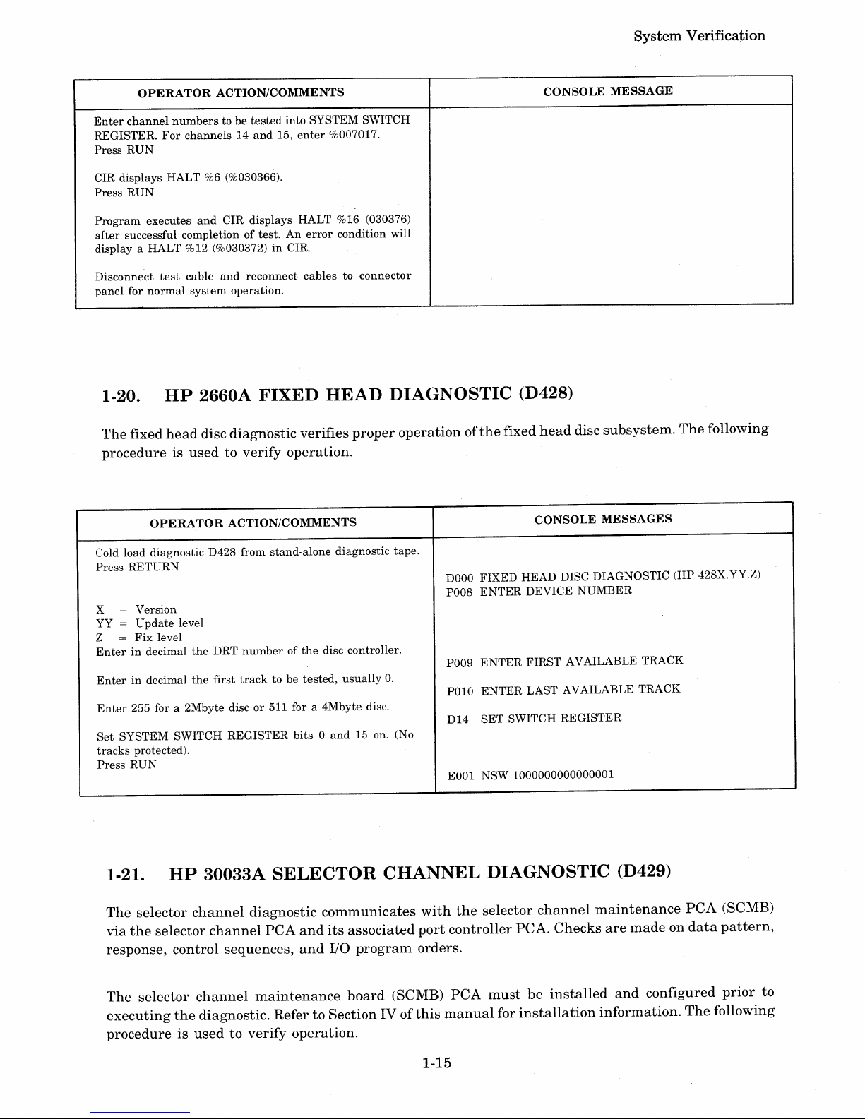
1-20.
HP
2660A
FIXED
HEAD
DIAGNOSTIC
(D428)
The
fixed
head
disc
diagnostic
verifies
proper
operationofthe
fixed
head
disc
subsystem.
The
following
procedureisusedtoverify
operation.
OPERATOR
ACTION/COMMENTS
Cold load diagnostic D428 from stand-alone diagnostic
tape.
Press
RETURN
X = Version
YY=Update
level
Z
=
Fix
level
Enterindecimal
the
DRT
numberofthe
disc controller.
Enterindecimal
the
first
track
to be
tested,
usually
O.
Enter
255 for a 2Mbyte discor511 for a 4Mbyte disc.
Set
SYSTEM SWITCH REGISTER
bits0and
15 on. (No
tracks
protected).
Press
RUN
CONSOLE
MESSAGES
DOOO
FIXED HEAD DISC DIAGNOSTIC (HP 428X.YY.Z)
P008
ENTER
DEVICE
NUMBER
P009
ENTER
FIRST
AVAILABLE TRACK
POlO
ENTER
LAST AVAILABLE TRACK
D14
SET
SWITCH REGISTER
E001 NSW 1000000000000001
1-21.
HP
30033A
SELECTOR
CHANNEL
DIAGNOSTIC
(D429)
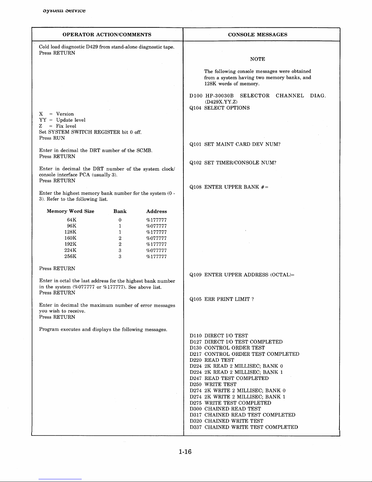
The
selector
channel
diagnostic
communicates
with
the
selector
channel
maintenance
PCA
(SCMB)
via
the
selector
channel
PCA
and
its
associated
port
controller
PCA.
Checks
are
madeondata
pattern,
response,
control
sequences,
and
I/O
program
orders.
The
selector
channel
maintenance
board
(SCMB)
PCA
must
be
installed
and
configured
prior
to
executing
the
diagnostic.
RefertoSection
IV of
this
manual
for
installation
information.
The
following
procedureisusedtoverify
operation.
1-15
Page 26
0YISLt:Hl
Ot:rVlCe
OPERATOR
ACTION/COMMENTS
Cold load diagnostic D429 from stand-alone diagnostic tape.
Press RETURN
x = Version
YY = Update level
Z = Fix level
Set
SYSTEM SWITCH REGISTER
bit0off.
Press
RUN
Enterindecimal
the
DRT
numberofthe
SCMB.
Press RETURN
Enterindecimal
the
DRT
numberofthe
system
clock/
console interface PCA (usually 3).
Press RETURN
Enter
the
highest
memory
bank
number
forthe
system(0-
3). Refer to
the
following list.
Memory
Word
Size
Bank
Address
64K
0
%177777
96K
1
%077777
128K
1
%177777
160K
2 %077777
192K
2 %177777
224K
3
%077777
256K
3 %177777
Press
RETURN
Enterinoctal
the
last
address for
the
highest
bank
number
in
the
system (%077777or%177777). See above list.
Press
RETURN
Enterindecimal
the
maximum
numberoferror
messages
you
wish
to receive.
Press
RETURN
Program
executes
and
displays
the
following messages.
CONSOLE
MESSAGES
NOTE
The following console messages were obtained
from a
system
having
two memory banks,
and
128K words of memory.
D100
HP-30030B
SELECTOR
CHANNEL
DIAG.
(D429X.YY.Z)
Q104 SELECT OPTIONS
Q101 SET MAINT CARD DEV NUM?
Q102
SET
TIMER/CONSOLE NUM?
Q108
ENTER
UPPER
BANK
#=
Q109
ENTER
UPPER
ADDRESS (OCTAL)=
Q105 ERR
PRINT
LIMIT?
DllO
DIRECT
110
TEST
D127 DIRECT
110
TEST
COMPLETED
D130 CONTROL ORDER TEST
D217 CONTROL ORDER
TEST
COMPLETED
D220 READ TEST
D224 2K READ 2 MILLISEC; BANK 0
D224 2K READ 2 MILLISEC; BANK 1
D247 READ TEST COMPLETED
D250 WRITE TEST
D274 2K WRITE 2 MILLISEC; BANK 0
D274 2K WRITE 2 MILLISEC; BANK 1
D275 WRITE
TEST
COMPLETED
D300 CHAINED READ
TEST
D317 CHAINED READ
TEST
COMPLETED
D320 CHAINED WRITE TEST
D337 CHAINED WRITE TEST COMPLETED
1-16
Page 27
System
Verification
OPERATOR
ACTION/COMMENTS
CONSOLE
MESSAGE
D340 ERROR
RESPONSE
TEST
D367 ERROR
RESPONSE
TEST
COMPLETED
D600 SELECTOR
CHANNEL
DIAG COMPLETED
D60l
ENDOFPASS
1
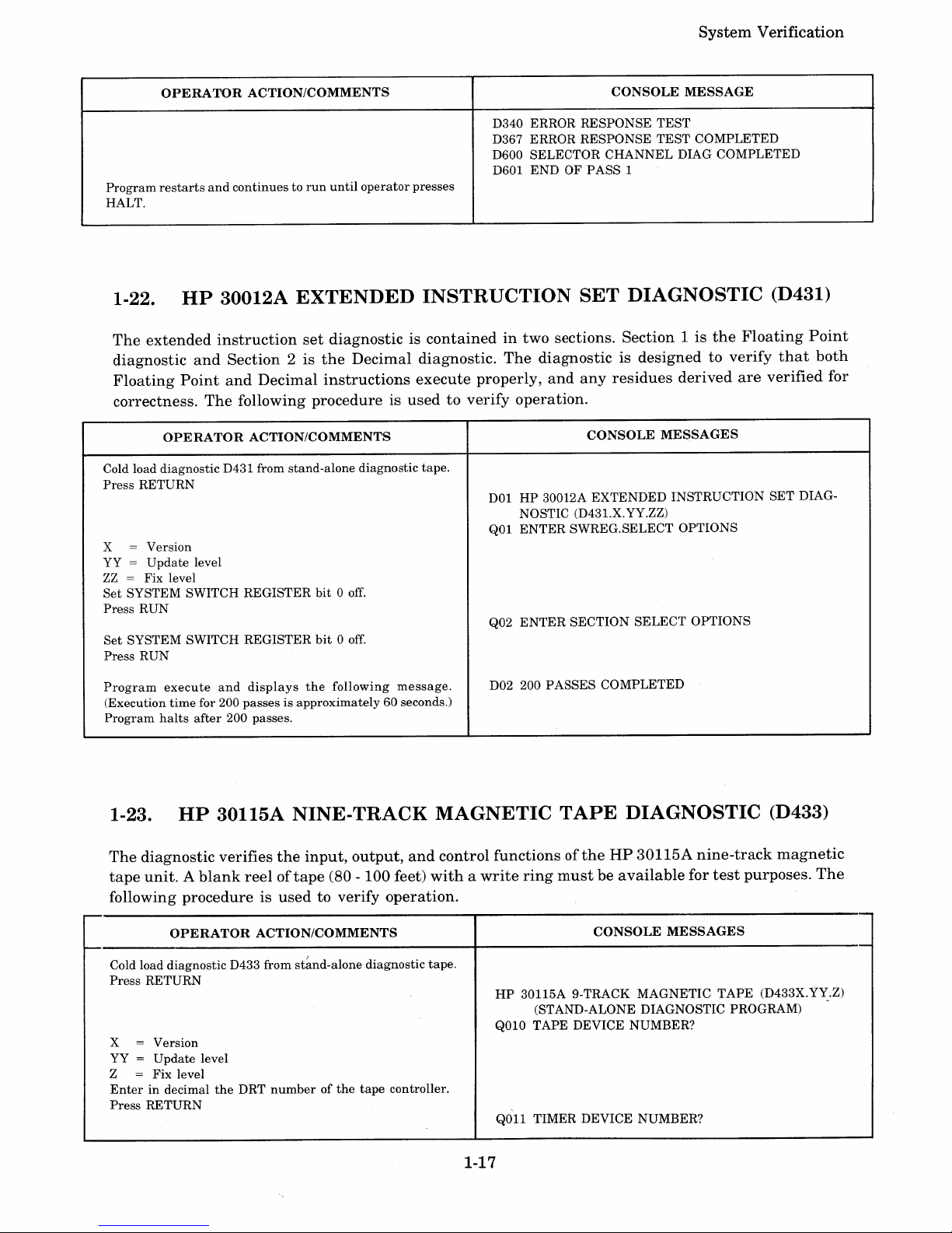
Program
restarts
and
continuestorun
until
operator
presses
HALT.
1-22.
HP
30012A
EXTENDED
INSTRUCTION
SET
DIAGNOSTIC
(D431)
The
extended
instruction
set
diagnosticiscontainedintwo
sections.
Section
1 is
the
Floating
Point
diagnostic
and
Section
2 is
the
Decimal
diagnostic.
The
diagnosticisdesignedtoverify
that
both
Floating
Point
and
Decimal
instructions
execute
properly,
and any
residues
derived
are
verified
for
correctness.
The
following
procedureisusedtoverify
operation.
OPERATOR
ACTION/COMMENTS
Cold load diagnostic
D43l
from stand-alone diagnostic tape.
Press
RETURN
x = Version
YY
=
Update
level
ZZ
= Fix level
Set
SYSTEM SWITCH REGISTER
bit0off.
Press
RUN
Set
SYSTEM SWITCH REGISTER
bit0off.
Press
RUN
Program
execute
and
displays
the
following
message.
(Execution
time
for 200
passesisapproximately
60 seconds.)
Program
halts
after
200 passes.
CONSOLE
MESSAGES
DOlHP30012A
EXTENDED
INSTRUCTION
SET
DIAG-
NOSTIC (D431.X.YY.ZZ)
QOl
ENTER
SWREG.SELECT OPTIONS
Q02
ENTER
SECTION
SELECT
OPTIONS
D02 200 PASSES COMPLETED
1-23.
HP
30115A
NINE-TRACK
MAGNETIC
TAPE
DIAGNOSTIC
(D433)
The
diagnostic
verifies
the
input,
output,
and
control
functionsofthe
HP
30115A
nine-track
magnetic
tape
unit.Ablank
reeloftape
(80 -
100
feet)
withawrite
ring
mustbeavailable
for
test
purposes.
The
following
procedureisused
to verify
operation.
OPERATOR
ACTION/COMMENTS
Cold load diagnostic D433 from
st~nd-alone
diagnostic tape.
Press
RETURN
X = Version
YY
=
Update
level
Z
=
Fix
level
Enterindecimal
the
DRT
numberofthe
tape
controller.
Press
RETURN
CONSOLE
MESSAGES
HP
30115A 9-TRACK
MAGNETIC
TAPE
(D433X.YY.Z)
(STAND-ALONE DIAGNOSTIC PROGRAM) .
QOlO
TAPE DEVICE NUMBER?
QOll
TIMER DEVICE NUMBER?
1-17
Page 28
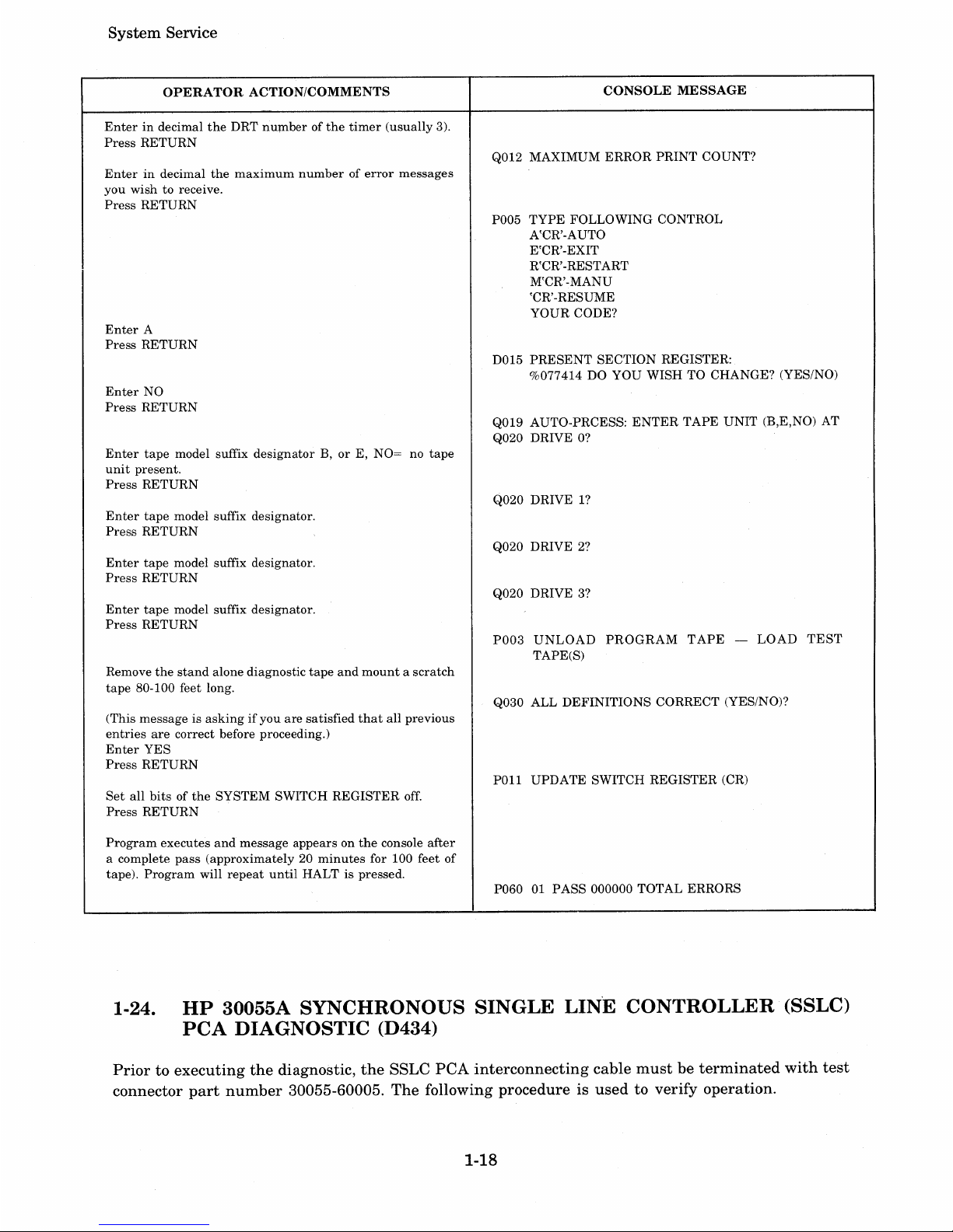
System Service
OPERATOR
ACTION/COMMENTS
Enterindecimal
the
DRT
numberofthe
timer
(usually
3).
Press
RETURN
Enterindecimal
the
maximum
numberoferror
messages
you
wish to receive.
Press
RETURN
Enter
A
Press
RETURN
Enter
NO
Press
RETURN
Enter
tape
model suffix
designatorB,or
E, NO= no
tape
unit
present.
Press
RETURN
Enter
tape
model suffix designator.
Press
RETURN
Enter
tape
model suffix designator.
Press
RETURN
Enter
tape
model suffix designator.
Press
RETURN
Remove
the
stand
alone diagnostic
tape
and
mountascratch
tape
80-100 feet long.
(This message is
askingifyou
are
satisfied
that
all previous
entries
are
correct before proceeding.)
Enter
YES
Press
RETURN
Set
all
bitsofthe
SYSTEM SWITCH REGISTER
off.
Press
RETURN
Program
executes
and
message appears on
the
console
after
a complete
pass
(approximately20minutes
for 100 feet of
tape).
Program
will
repeat
until
HALT is pressed.
CONSOLE
MESSAGE
Q012 MAXIMUM
ERROR
PRINT
COUNT?
P005
TYPE
FOLLOWING CONTROL
A'CR'-AUTO
E'CR'-EXIT
R'CR'-RESTART
M'CR'-MANU
'CR'-RESUME
YOUR CODE?
D015
PRESENT
SECTION REGISTER:
%077414 DO YOU WISH TO CHANGE? (YES/NO)
Q019 AUTO-PRCESS:
ENTER
TAPE
UNIT
(B,E,NO) AT
Q020 DRIVE
O?
Q020 DRIVE
1?
Q020 DRIVE 2?
Q020 DRIVE 3?
P003
UNLOAD
PROGRAM
TAPE
-
LOAD
TEST
TAPE(S)
Q030 ALL
DEFINITIONS
CORRECT (YES/NO)?
POll
UPDATE
SWITCH REGISTER (CR)
P060
01
PASS
000000 TOTAL ERRORS
1-24.
HP
30055A
SYNCHRONOUS
SINGLE
LINE
CONTROLLER
(SSLC)
PCA
DIAGNOSTIC
(D434)
Priortoexecuting
the
diagnostic,
the
SSLC
PCA
interconnecting
cable
mustbeterminated
with
test
connector
part
number
30055-60005.
The
following procedure is
used
to verify operation.
1-18
Page 29
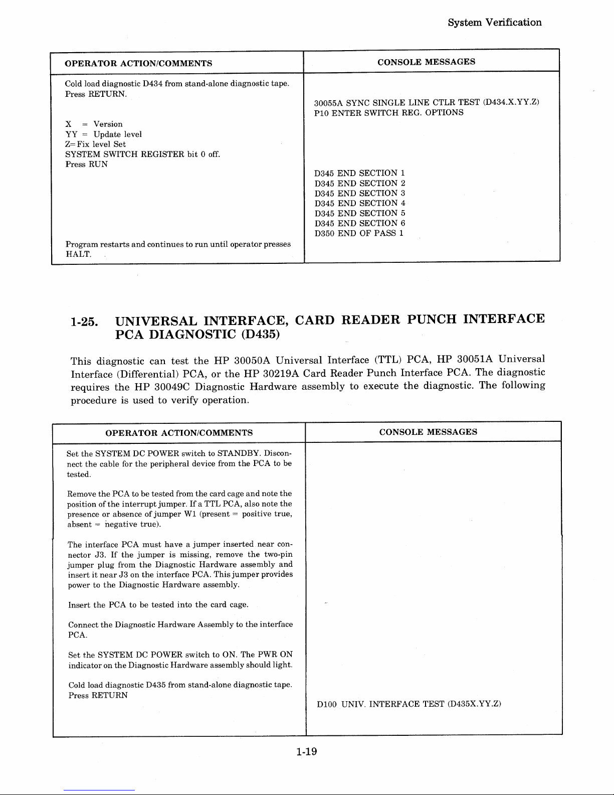
OPERATOR
ACTION/COMMENTS
Cold load diagnostic D434 from stand-alone diagnostic tape.
Press
RETURN.
x = Version
YY
=
Update
level
Z=
Fix
level
Set
SYSTEM SWITCH REGISTER
bit0off.
Press
RUN
Program
restarts
and
continuestorun
until
operator
presses
HALT.
System
Verification
CONSOLE
MESSAGES
30055A SYNC
SINGLE
LINE
CTLR
TEST
(D434.X.YY.Z)
PIO
ENTER
SWITCH REG. OPTIONS
D345
END
SECTION
1
D345
END
SECTION 2
D345
END
SECTION
3
D345 END SECTION 4
D345
END
SECTION 5
D345
END
SECTION
6
D350
ENDOFPASS
1
1-25.
UNIVERSAL
INTERFACE,
CARD
READER
PUNCH
INTERFACE
PCA
DIAGNOSTIC
(D435)
This
diagnostic
can
test
the
HP
30050A
Universal
Interface
(TTL)
PCA,
HP
30051A
Universal
Interface
(Differential)
PCA,orthe
HP
30219A
Card
Reader
Punch
Interface
PCA.
The
diagnostic
requires
the
HP
30049C
Diagnostic
Hardware
assemblytoexecute
the
diagnostic.
The
following
procedureisusedtoverify
operation.
OPERATOR
ACTION/COMMENTS
CONSOLE
MESSAGES
Set
the
SYSTEM DC
POWER
switch to STANDBY. Discon-
nect
the
cable for
the
peripheral
device from
the
PCA to be
tested.
Remove
the
PCA
to be
tested
from
the
card cage
and
note
the
positionofthe
interrupt
jumper.Ifa TTL PCA, also note
the
presenceorabsenceofjumperWI(present
= positive
true,
absent=negative
true).
The interface
PCA
must
haveajumper
inserted
near
con-
nector
J3.Ifthe
jumperismissing, remove
the
two-pin
jumper
plug
from
the
Diagnostic
Hardware
assembly
and
insertitnearJ3on
the
interface
PCA.
This
jumper
provides
power to
the
Diagnostic
Hardware
assembly.
Insert
the
PCA to be
tested
into
the
card cage.
Connect
the
Diagnostic
Hardware
Assembly to
the
interface
PCA.
Set
the
SYSTEM DC
POWER
switch
to ON. The
PWR
ON
indicatoron
the
Diagnostic
Hardware
assembly should light.
Cold load diagnostic D435 from stand-alone diagnostic tape.
Press
RETURN
DIOO
UNIV.
INTERFACE
TEST
(D435X.YY.Z)
1-19
Page 30
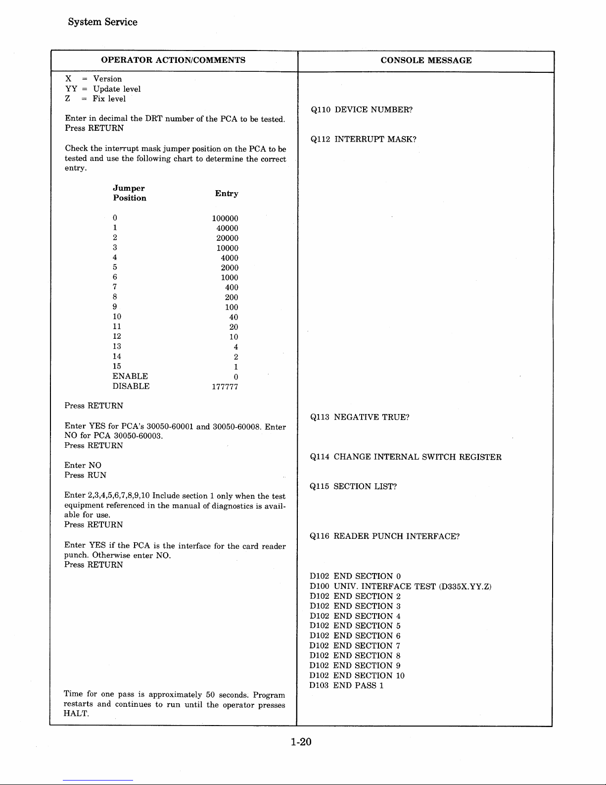
System Service
OPERATOR
ACTION/COMMENTS
x = Version
YY
= Update level
Z
= Fix level
Enterindecimal
the
DRT
numberofthe
PCA to be tested.
Press
RETURN
Check
the
interrupt
mask
jumper
position on
the
PCA to be
tested
and
use
the
following
chart
to determine
the
correct
entry.
CONSOLE
MESSAGE
Q110 DEVICE NUMBER?
Q112 INTERRUPT MASK?
Jumper
Position
o
1
2
3
4
5
6
7
8
9
10
11
12
13
14
15
ENABLE
DISABLE
Press
RETURN
Entry
100000
40000
20000
10000
4000
2000
1000
400
200
100
40
20
10
4
2
1
o
177777
Enter
YES for PCA's 30050-60001
and
30050-60008.
Enter
NO for PCA 30050-60003.
Press
RETURN
Enter
NO
Press
RUN
Enter
2,3,4,5,6,7,8,9,10 Include section 1 only
when
the
test
equipment
referencedinthe
manual
of diagnostics is available for use.
Press
RETURN
Enter
YESifthe
PCA is
the
interface for
the
card
reader
punch. Otherwise
enter
NO.
Press
RETURN
Time for one
pass
is approximately 50 seconds.
Program
restarts
and
continuestorun
until
the
operator
presses
HALT.
Ql13
NEGATIVE TRUE?
Q114 CHANGE INTERNAL SWITCH REGISTER
Q115 SECTION LIST?
Q116 READER
PUNCH
INTERFACE?
D102
END
SECTION 0
D100 UNIV. INTERFACE
TEST
(D335X.YY.Z)
D102
END
SECTION 2
D102 END SECTION 3
D102 END SECTION 4
D102
END
SECTION 5
D102
END
SECTION 6
D102
END
SECTION 7
D102
END
SECTION 8
D102
END
SECTION 9
D102 END SECTION 10
D103
END
PASS 1
1-20
Page 31

1-26.
System
Verification
HP
30061A
TERMINAL
CONTROLLER
INTERFACE
(TCI)
PCA
DIAGNOSTIC (D438)
The
TCl
diagnostic
tests
the16channelsofthe
terminal
controller.
Test
cable
30062-60003isrequired
to
execute
the
diagnostic.
The
test
cable is
initially
connected
between
channels0and1on
the
the
HP
30062A
Terminal
Controller/Multiplexer
Connector
Panel
and
then
connectedtothe
next
sequential
pair
of
channels
until
all
channels
have
been
tested.
The
following
procedureisused
to
verify
operation.
OPERATOR
ACTION/COMMENTS
NOTE
Tag
and
identify
all
cable
connectorsonHP
30062A
Connector
Panel,
locatedatthe
rear
of
equipment
bay
1 before proceeding.
Disconnect
all
cable
connectors fromHP30062A
Connector
Panel.
Connect
test
cable
30062-60003
between
channels0and1on
the
connector
panel.
Cold load
diagnostic
D438 from
stand-alone
diagnostic
tape.
Program
loads
and
displays
HALT
%6 (%030366)inCIR.
Select
switch
register
optionsbysetting
all
bitsofSYSTEM
SWITCH
REGISTER
off.
Press
RUN
CIR
displays
HALT
%7 (%030367)
Enter
channel
numbers
tobetested
into
SYSTEM
SWITCH
REGISTER.
For
chan-
nels0and1,enter
%000001.
Press
RUN
CIR
displays
HALT
%6 (%030366).
Press
RUN
Program
executes
and
CIR
displays
HALT
%16 (%030376)
after
successful
completionofthe
test.Anerror
condition
will
displayaHALT
%12 (%030372)inCIR.
Disconnect
test
cable from
channels0and1,and
reconnect
between
channels2and
3.
Enter
channel
numbers
to be
tested
into
SYSTEM
SWITCH
REGISTER.
For
channels2and3,enter
%001003.
Press
RUN
CIR
displays
HALT
%6 (%030366).
Press
RUN
Program
executes
and
CIR
displays
HALT
%16 (%030376)
after
successful
completionoftest.Anerrpr
condition
will
displayaHALT
%12 (%030372)inCIR.
Disconnect
test
cable
from
channels2and3,and
reconnect
between
channels4and
5.
Enter
channel
numbers
to be
tested
into
SYSTEM
SWITCH
REGISTER.
For
channels4and5,enter
%1002005.
Press
RUN
CIR
displays
HALT
%6 (%030366).
Press
RUN
1-21
CONSOLE
MESSAGES
NOTE
No console
messages
are
obtained
during
this
diagnostic.
Page 32

i:>ysI;em i:>erVlCe
OPERATOR
ACTION/COMMENTS
CONSOLE
MESSAGE
Program
executes
and
CIR displays HALT %16 (%030376)
after
successful completionoftest.Anerror
condition will
display a HALT
%12 (030372)
in
CIR.
Disconnect
test
cable from
channels4and5,and
reconnect
between
channels6and
7.
Enter
channel
numbers
to be
tested
into
SYSTEM SWITCH
REGISTER.
For
channels6and7,enter
%003007.
Press
RUN
CIR displays HALT %6 (%030366).
Press
RUN
Program
executes
and
CIR displays HALT %16 (%030376)
after
successful completionoftest.Anerror
condition will
display a HALT
%12 (%030372) in CIR.
Disconnect
test
cable from
channels6and7,and
reconnect
between
channels8and
9.
Enter
channel
numbers
to be
tested
into SYSTEM SWITCH
REGISTER.
For
channels8and9,enter
%00401I.
Press
RUN
CIR displays HALT %6 (%030366).
Press
RUN
Program
executes
and
CIR displays HALT %16 (%030376)
after
successful completion of test.Anerror
condition will
display a HALT
%12 (%030372) in CIR.
Disconnect
test
cable from
channels8and9,and
reconnect
between
channels10and
II.
Enter
channel
numbers
to be
tested
into
SYSTEM SWITCH
REGISTER.
For
channels10and
11,
enter
%005013.
Press
RUN
CIR displays HALT %6 (%030366).
Press
RUN
Program
executes
and
CIR displays HALT %16 (%030376)
after
successful completionoftest.Anerror
condition will
"
display a HALT %12 (%030372)inCIR.
Disconnect
test
cable from
channels10and
11,
and
recon-
nect
between
channels12and
13.
Enter
channel
numbers
to be
tested
into
SYSTEM SWITCH
REGISTER.
For
channels12and
13,
enter
%006015.
Press
RUN
CIR displays HALT %6 (%030366).
Press
RUN
,·Program
executes
and
CIR displays HALT %16 (%030376)
after
successful completionoftest.Anerror
condition will
display a HALT
%12 (%030372)
in
CIR.
Disconnect
test
cable from
channels12and
13,
and
recon-
nect
between
channels14and
15.
1-22
Page 33

System
Verification
OPERATOR
ACTION/COMMENTS
CONSOLE
MESSAGE
Enter
channel
numberstobe tested
into
SYSTEM SWITCH
REGISTER.
For
channels14and
15,
enter
%007017.
Press
RUN
CIR displays HALT
%6
(030366).
Press
RUN
Program
executes
and
CIR displays HALT %16 (%030376)
after
successful completion of test.Anerror
condition will
display a HALT %12 (%030372)
in
CIR.
Disconnect
test
cable
and
reconnect
cables to connector
panel
for
normal
system
operation.
1-27.
HP
30226A
PLOTTER
INTERFACE
DIAGNOSTIC
(D439)
This
diagnostic is divided
into
two sections. Section I is performed
withatest
connector
(part
number
30226-60003) connectedinplaceofthe
plotter
cable.
This
section
tests
the
interface
PCA. Section 2
tests
the
basic
operationofthe
CalComp
plotter
when
connectedtothe
interface
PCA.
The
following
procedure is
used
to verify operation.
OPERATOR
ACTION/COMMENTS
Cold load diagnostic D439 from stand-alone diagnostic tape.
Press
RETURN
x = Version
YY
= Update level
Z =
Fix
level
Set
SYSTEM SWITCH REGISTER
bit0off.
Press
RUN
Program
stops
and
displays HALT 7inCIR (%030367).
After
installing
the
connector,
press
RUN
Program
executes SectionI.(HALT 7inCIR, %030367)
Connect
plotter
cable, place
plotter
power on.
Press RUN
CONSOLE
MESSAGES
D326
PLOTTER
INTERFACE
DIAGNOSTIC
(HP
32367X.YY.Z)
ENTER
SWITCH REGISTER OPTIONS
PROPERLY
INSTALL
THE
30226-60003
TEST
CONNECTOR
CONNECT PLOTTER TO INTERFACE PLACE PLOTTER
POWER ON,
INSURE
UNIT
IS NOTINSTANDBY
WHAT IS
THE
INCREMENT/INCH
RATIO
OF
YOUR
PLOTTER?
Step
Size
.01 in.
.005 in.
.0025 in.
.002 in.
.10
mm
.05
mm
Operator
Entry
100
200
400
500
200
500
Press RETURN
after
the
entry.
Enter
YES or NO
Press RETURN
(If
YES,goto procedure
B)
Enter
YES or NO
Press RETURN
TYPE 500
PLOTTER?
IS
THE
LIMIT SWITCH OPTION AVAILABLE?
IS
THE
READY/NOT READY OPTION
AVAILABLE?
1-23
Page 34

System Service
+Y,+x
01
8
-x
+X
068........
-------~~-------
..
~
02
8
+Y,
-x
07
8
-
Y,-X
05
8
-y
04
8
-V,
+X
03
8
7522-18
Figure
1-2.
Type
500
Plot
+Y,
-x
+Y,-X/2
+Y
+Y,
+X/2
+Y,+X
07
8
33
8
00
8
32
8
01
8
"-
t
/
+Y/2,
-x
+Y
/2,
+x
31
8
30
8
-x -
X/2
068....
26
8
- Y /2, - X
+y
/2,
+X
35
8
34
8
/
•
"
-V,
-x
-Y,-X/2
-Y
-Y,
+X/2
-Y,
+X
05
8
37
8
04
8
36
8
03
8
7522-19
Figure
1-3.
Type
6001700
Plot
1-24
Page 35

OPERATOR
ACTION/COMMENTS
Enter
YESorNO
Press
RETURN
(If
the
plotter
is a type 600or700
and
the
Ready/Not
Ready
option is
not
installed,
go to procedure
A.)
Place
plotter
power off
and
enter
Y to continue.
Turn
plotter
power on
and
enter
Y to continue.
A
Ifthe
plotter
is a type 600or700
and
the
Limit
Switch
option
is
installed,
the
message is:
Strike
the
limit
switch
with
the
pen
and
enter
Y to continue.
B
Place
the
peninthe
centerofplotter
chart,
enter
Y to
continue.
Program
runs
until
the
following message is displayed:
(Plot for a
type
500
plotter
is shown in figure 1-2,
and
for a
type 600
or
700
plotter
see figure 1-3).
System
Verification
CONSOLE
MESSAGE
PLACE PLOTTER
POWER
OFF
PLACE PLOTTER
POWER
ON,
ENSURE
UNIT
ISN'T
IN
STANDBY
STRIKE
THE
LIMIT SWITCH WITH
THE
PEN
PLACE
PENINCENTEROFPLOTTER
CHART
D328
ENDOFPLOTTER
INTERFACE
DIAGNOSTIC
1-28.
HP
3000
SERIES
II
COMPUTER
SYSTEM
CPU
DIAGNOSTIC
(D420)
~he
diagnostic
tests
all
the
instructions
and
mostofthe
conditions
that
resultininterrupts
and
traps
by
the
CPU.
The
diagnosticisdivided
into14parts.
Only
the
first five
parts
shouldberun
whennoHP
30354A
Maintenance
Panelisconnectedtothe
system.
The
remaining
nine
parts
require
the
.mainte-
nance
panel
for
observing
data.
Refertothe
CPU
stand-alone
diagnostic
manual
(30003-90001) for
detailsofhowtoexecute
the
remaining
nine
partsofthe
diagnostic.
The
following
procedureisused
to
verify
operation.
OPERATOR
ACTION/COMMENTS
CONSOLE
MESSAGE
Cold
load
CPU
cold
load
diagnostic
tape,
part
number
NOTE
30000-10016/11016. (Leave
the
SYSTEM SWITCH REGIS-
TER
set
to %003006.) This cold loads
part1ofthe
diagnostic.
No console
messages
are
obtained
during
this
Press
RUN
diagnostic.
CIR
containsaPAUSE
(%030020)
Press
HALT
Computer should HALT.
Press
RUN
(Program
runs
approximately
45 seconds.
CIR
displays
HALT %15, %030375,
indicating
endofpart
1.)
Cold load
part
2 by
pressing
LOAD
and
ENABLE.
Press
RUN
(Program
runs
approximately
50 seconds.
CIR
displays
HALT %15, %030375,
indicating
endofpart
2.)
Cold load
part
3 by
pressing
LOAD
and
ENABLE.
Press
RUN
(Program
runs
approximately
4 seconds. CIR
displays
HALT
%15, %030375,
indicating
endofpart
3.)
1-25
Page 36

System
Service
OPERATOR
ACTION/COMMENTS
CONSOLE
MESSAGE
Cold load
part
4 by
pressing
LOAD
and
ENABLE.
Press
RUN
(Program
runs
approximately
4 seconds. CIR displays HALT
%15, %030375,
indicating
endofpart
4.)
Cold load
part
5 by
pressing
LOAD
and
ENABLE.
Press
RUN
(Program
runs
approximately
50 seconds.
CIR
displays
HALT %15, %030375,
indicating
end of
part
5.)
1-29.
HP
30104A
PAPER
TAPE
READER,
HP
30105A
PAPER
TAPE
PUNCH
ON-LINE
VERIFICATION
PROGRAM
On-line
verificationofthe
paper
tape
punchisperformed
independently
from
the
paper
tape
reader.
Both
subsystems
may
not
alwaysbepresentinthe
system
configuration.
1·30.
PAPER
TAPE
PUNCH
VERIFICATION.
To
verify
operationofthe
paper
tape
punch,
perform
the
following steps:
1. Log
onto
the
system.
:HELLO
FIELD.SUPPORT,HP32230
2.
Set
up
the
punch
file
command,
where
LDN=the
logical device
nameofthe
tape
punch.
:FILE
OUT;DEV=
LDN;REC=
-72,I,F,ASCII
3.
Output
the
numerals,
alphabet,
and
special
characters
from
the
terminal
to
tape
punch
using
FCOPY.
:RUN
FCOPY.PUB.SYS
HP32212A.XX.YY
FILE
COPIER
(C)
HEWLETT/PACKARD
CO.
1976
>FROM=
;TO=*OUT
4.
The
following
message
willbeoutputbyFCOPYifthe
terminalisnot
setupas
a 72
byte
device.
The
message
canbeignored,
enteraRETURN.
*200*
5.
Input
eachofthe
following
linesatthe
terminal.
Terminate
each
line
withaRETURN.
1234567890
ABCDEFGHIJKLMNOPQRSTUVWXYZ
1"#$%&'( )=-",,@@+*;:<>?,.1
6.
Enter
yc (control Y)' to
terminate
the
input
phase.
1-26
Page 37

System
Verification
7.
The
following
message
appears
on
the
terminal.
<CONTROL
Y>
4 RECORDS PROCESSED ***0 ERRORS
8.
Terminate
FCOPYbyentering
the
following:
>EXIT
9.
Compare
the
tape
just
produced
with
figure 1-4,
the
two
tapes
should
be identical.Ifthe
tapes
differ,
use
SLEUTHtodetermine
the
problem
with
the
paper
tape
punch.
r.
PACKARD
•••••••
A.l:i2
n
+ttIW4..«.Jt.,IACKARD
••
it
rrA~
I-II='WLETT.
••••••••••
'f
~
~..........
~~.~~.
•••••••••••
••••••••••••••
•••••
•
••••
••••••••
•••
••
•••••
•••••••••••
•
••••••••••••••••••••••••••••••••••••••••••••••••••••••••••••••••••••••••
•••• • •••• •••• •••• • •••• ••• •••••• •
••
••
••••
•• •• •• •• ••
•••••••
•••• ••
•••
•
• • • • • •• • • • • • • • • • • • • • •• • • • • •••
••
• •••
Figure
1-4.
Master
Tape
1-31.
PAPER
TAPE
READER
VERIFICATION.
To
verify
operation
of
the
paper
tape
reader,
perform
the
following steps:
1.
Log onto
the
system.
:HELLO
FIELD.SUPPORT,HP32230
2.
Setupthe
reader
file command,
where
LDN =
the
logical device
nameofthe
paper
tape
reader.
:FILE IN;DEV= LDN;REC=
-72,I,F,ASCII
3.
If
the
readerisa job accepting device,
the
follC'wing
entries
are
requiredatthe
system
console to
make
the
reader
non-job accepting.
=REFUSE
LDN
= ABORTIO
LDN
4.
Use
FCOPYtoread
from
the
tape
reader
and
writetothe
terminal.
:RUN FCOPY.PUB.SYS
HP32212A.XX.YY
FILE
COPIER
(C)
HEWLETT-PACKARD CO. 1976
>FROM=IN;TO=
5. Place
the
paper
tape
(30204-80003)
supplied
with
the
reader
into
the
read
head
leaving
some
leader
behind
the
read
head.
6.
Answer
the
110
requestonthe
system
console
with
the
PIN
and
logical device
numberofthe
tape
reader.
1-27
Page 38

System Service
7.
If
the
terminal
is configured for
anything
greater
than
72 byte records, FCOPY will
output
the
following message. The message
can
be ignoredbyentering
a RETURN.
*200*
8. The following
characters
should be displayedatthe
terminal.
Verify
that
all
characters
are
correct.Ifthe
characters
are
incorrect,
use
SLEUTH
to locate
the
problem.
1234567890
ABCDEFGHIJKLMNOPQRSTUVWXYZ
!"#$%&'()=
- ",@@+*;:<>?,.I
9.
The following message
appearsonthe
terminal:
EOF
FOUND
IN
FROM FILE AFTER RECORD 2
3 RECORDS PROCESSED ***0 ERRORS
10.
Terminate
FCOPY by entering:
>EXIT
1-32. HP
7920A
DISC DRIVE
VERIFIER,
SLEUTH07
The
SLEUTH07 program verifies
the
operationofan
HP
7920A
Disc Drive,
formats
disc packs,
and
checks packs
for
surface damage.
The
program, which resides in
the
field
support
account,
must
be copiedtomagnetic
tape
for
subsequent
loading
after
the
MPE Operating Systemisshut
down.
Detailed instructions
for
loading
and
running
SLEUTH07 can be
foundinthe
HP
7920A
Disc Drive
Verifier SLEUTH07 Manual (part
number
32230-90002).
The following
procedure
summarizes disc verification.
OPERATOR
ACTION/COMMENTS
Program destroys data stored on customer's disc
pack(s).
Be
sure customer has dumped
MPE
Sys-
tem using a 0 dump date.
Cold load SLEUTH 3000 from I/O stand-alone
diagnostic tape.
Press RUN on System Control Panel. Press
RETURN on Console.
Mount tape containing SLEUTH07 and enter:
BAE
Type the SLEUTH RUN command.
1-28
CONSOLE MESSAGES/COMMENTS
>10
(a
typical prompt for input)
>670
(a typical prompt for input)
7920 VERIFIER, ENTER DRT
#
JAN
1977
Page 39

OPERATOR
ACTION/COMMENTS
Enter DRT numberofdisc controller.
Enter 1
Enter a unit number 0 through 7. Set Unit Select
Switch
on
disc drivetothe same number. Press
RUN on the System Control Panel.
Question
is
repeated until you test eight numbers.
Then testing continues.
Respond with a logical unit number, 0 through
7.
Type a one (1)toinitialize the pack.
Type a one (1)
to
check the disc pack for surface
damage.
Type a zero (0) for a short pass.
Type a one (1) for a long pass.
HP
30310A
Power
Supply
CONSOLE MESSAGES/COMMENTS
UNIT SELECT SWITCH TEST?
(0=N,1=Y)
ENTER UNIT
#,
SET SWITCH TO UNIT #
ENTERED, PRESS RUN
ENTER UNIT
#,
SET SWITCH TO UNIT #
ENTERED, PRESS RUN.
ENTER UNIT # TO
BE
TESTED
FORMAT PACK?
(O=N,
1=Y)
VERIFY
PACK?
(O=N,
1=Y)
VERIFY LONG PASS?
(O=N,
1=Y)
BEGIN FORMAT
END FORMAT
BEGIN VERIFY
VERIFY PASS
#1
VERIFY
PASS
#2
VERIFY
PASS
#3
END VERIFY
(Takes
about10minutes)
(For
short
and long pass;
takes
about
7 minutes.)
(For
long pass only; takes
about
14 minutes.)
BEGIN
MAIN
END HEAD TEST
END TRACK SWITCH TEST
ENDW/RTEST
(Main tests require
about
5 minutes.)
Type RUN
to
repeat SLEUTH07 executionorhalt
the system.
JAN
1977
1-29
>670
(a typical
prompt
for input)
Page 40

System Service
1-33.
HP
30360AHARDWIRED SERIAL INTERFACE (HSI)
PCA
DIAGNOSTIC (D432)
The diagnostic verifies the input,
output,
and
control functionsofthe
HP 30360A Hardwired Serial
Interface (HSI)
peA.
The following procedure is usedtoverify operation.
NOTE
Priortorunning
the
diagnostic, set
the
TEST/NORMAL switch
(on
the
HSI cable assembly,
part
no.
30360-60003)toTEST
for
the
channeltobe tested.
OPERATOR ACTION/COMMENTS
Cold load diagnostic D432 from stand-alone diagnostic
tape. Press RETURN.
x = Version
YY
= Update level
Z
= Fix level Set
SYSTEM SWITCH REGISTER bit 0 off.
Press RUN
Program restarts and continues
to
run until operator
presses HALT.
1-30
CONSOLE MESSAGE
HP
30360A HARDWIRED SERIAL INTERFACE
DIAGNOSTIC (D432X.YY.Z)
ENTER SWITCH REG. OPTIONS
D400 END SECTION 1
D400 END SECTION 2
D400 END SECTION 3
D400 END SECTION 4
D400 END SECTION 5
D400 END SECTION 6
D500 END OF PASS
1
MAR 1977
Page 41

SYSTEM
TROUBLESHOOTING
I~
2-1. INTRODUCTION
This
section
contains
the
system
troubleshooting
procedures
andalistofmaterials
requiredtosupport
the
procedures.
The
troubleshootingisperformed
on
the
CPU,
memory,
multiplexer
channel,
and
selector
channel.
2-2. PURPOSE
The
system
troubleshooting
flowchart, figure 2-1,isdesignedtoisolateafault
to a
functional
area
of
the
system.
References
are
providedinthe
flowchart to
manuals
and
procedures
that
mayberequired
to
perform
certain
procedures.
Repairofa defective
functional
areaisusually
accomplishedbyreplacementofthe
defective PCA.
Only
the
Semiconductor
Memory
Array
PCA
(30008-60002)
and
the
Fault
Correcting
Array
PCA
(30009-60001)
are
repairedtothe
component
level.
Replacementofthe
memory
array
chips
can
only
be
performedbythose
specifically
trainedinthis
procedure.
Attempting
replacementbynon-trained
personnel
can
ruin
the
PCA.
NOTE
OnlyICmemory
chips
marked
with
HP
part
number
5080-4560
can
be
used
for
replacements.
Reliabilityofthe
PCA
will be
seriously
degradedifthis
noteisnot
observed.
2-3. FACILITIES REQUIRED
The
specific
items
requiredtoperform
the
troubleshootingonthe
system
are
listedintable
2-1.
Table
2-1.
Facilities
Required
HP 30345A Maintenance Panel
Stand-Alone Diagnostics
System Verification Tape and Listing
CPU Diagnostic Listings (Sections 1 through
5)
Known Good SYSDUMP Tape
DEC
1976
2-1
Page 42

System Service
t
SE
THE
QA
VERIFICATION
TAPE
AND
-
INSTRUCTIONS
PROVIDED
ON
THE
VERIFICATION
LISTING
YES
USE
THE
MANUAL
INDEXINTHE
CUSTOMER SUPPORT
HANDBOOK
TO
~
~
DETERMINE
THE
APPLICABLE
SUB-
SYSTEM
MANUAL
FOR
TROUBLESHOOT-
ING
RUN
THE
SYSTEM
TEST
REFERTO}
APPENDIX
A -
RUN
THE
MICRO-
DIAGNOSTIC
FOR
THE
CPU REGISTER
TEST
PROBLEM
CORRECTED.
RETURN
THE
SYSTEMTOTHE
CUSTOMER
CALL
PRODUCT
SPECIALIST
FOR ASSISTANCE
CALL
PRODUCT
SPECIALIST
FOR
ASSISTANCE
U
EFERTO
r-
PARAGRAPH
I
2·10.
REFER
TO
PARAGRAPH
I 2-11.
STEP
THROUGH
THE
MICROCODE
FOR
COLD
LOAD
FROM
TAPE
l
~{
RUN
THE
MICRO·
DIAGNOSTIC
FOR
THE
MEMORY
CONFIGURATION
TEST
REFER
TO
PARAGRAPH
I 2-9. I
DIAGNOSE
AND
REPAIR THE
PROBLEM
j
REF~R
TO
I
PARAGRAPH
2-4.
DIAGNOSE
AND
REPAIR
THE
CPU
PROBLEM
I REFERTOI
PARAGRAPH
2-5.
DIAGNOSE
AND
REPAIR
THE
MEMORY
PROBLEM
Figure
2-1.
System
Troubleshooting
Flowchart
2-2 DEC
1976
Page 43

System Troubleshooting
{
REFERTOTHE
CONSOLE
OPERATOR'S
GUIDE
30000-90013
FOR
-----
OPERATING
INSTRUCTIONS
AND
CONSOLE
REPLIES
RELOAD
MPE
cr
{
THREE
POSSIBLE
PATHS
EXIST
AT
THIS
POINT.ITIS
SUGGESTED
- - - -
--------
-
-----
THAT
EACH
PATHBETA.KEN
IN
SEQUENCE AS
REQUIRED
TO
ISOLATE
THE
PROBLEM
AREA.
WHICH
PASS IS
THIS,
1,2,OR3
?
COOLSTART
MPE
WARMSTART
MPE
THE
FOLLOWING
MESSAGES
SHOULD
APPEARATTHE
SYSTEM CONSOLE
CALL
PRODUCT
SPECIALIST
FOR
ASSISTANCE
Figure
2-1.
System
Troubleshooting
Flowchart
(Continued)
DEC
1976
2-3
Page 44

System Service
AT
THE
COMPLETION
OF A
SUCCESSFUL DUMP, CIR
SHOULD
CONTAIN
THE
FOLLOWING
OCTAL
VALUE
FOR
THE
CORRESPONDING
SYSTEM
MEMORY
SIZE:
t
HALT
THE
SYSTEM
AND
AT
THE
SYSTEM
CONTROL
_ _
PANEL,
SIMULTANEOUS.L
Y
PRESS
THE
ENABLE
AND
DUMP SWITCHES.
TAPE
SHOULD
MOVE.
MEMORY
SIZE
64K
96K
112K
128K
160K
192K
224K
256K
CIR
000001
100001
140001
000002
100002
000003
100003
000004
YES
PERFORM
A
COLD
DUMP
OPERATION
NO
MAKE
TWO MORE
ATTEMPTS
TO
GET
A SUCCESSFUL
COLD
DUMP
l
RE_STARTTHE
SYSTEM
VIA
THE
COLD
LOAD,COOLSTART,WARMSTART,OR
_ _
RELOAD.
LOG-ON
THE
SYSTEM.
MOUNT
COLD
DUMP TAPE.
ENTERATCONSOLE
:RUN
DPAN2.
PUB. SYS
CALL
PRODUCT
SPECIALIST
FOR
ASSISTANCE
ANALYZE
THE
COLD
DUMP
{
ASSISTANCE
FROM
-
PRODUCT
SPECIALIST
MAYBEREQUIRED
SEND
THE
COLD
DUMP
AND
LOAD
MAP
FOR
ANALYSIS.
RETURN
SYSTEM
TO CUSTOMER
DIAGNOSE
AND
FIX
PROBLEM
CALL
PRODUCT
SPECIALIST
FOR
ASSISTANCE
t
OAD
MAP
CAN
BE
OBTAINED
WHEN
THE SYSTEM
IS
-
RESTARTED
BY
ANSWERING. CONSOLE
DIALOGUE
Figure
2-1.
System
Troubleshooting
Flowchart
(Continued)
2-4 DEC
1976
Page 45

REFER
Tol
SECTION
IJ-
RUN
CPU
STAND-ALONE
DIAGNOSTIC
0420
RUN
FAULT
CORRECTION
MEMORY
DIAG·
NOSTIC
0430
DIAGNOSE
SYSTEM
TEST
FAILURE
NO
REFER
TO
SECTION I
System
Troubleshooting
DIAGNOSE
AND
REPAIR
CPU
PROBLEM
REFER
TO
I
PARAGRAPH
2-6.
DIAGNOSE
AND
REPAIR
MEMORY
t--
...
t---t~
PROBLEM
I
REFER
TO I
PARAGRAPH
2-7.
CALL
PRODUCT
SPECIALIST
FOR
ASSISTANCE
DIAGNOSE
AND
REPAIR
PROBLEM
I
REFER
TO
PARAGRAPH
2-8.
DEC
1976
Figure
2-1.
System
Troubleshooting
Flowchart
(Continued)
2-5
Page 46

System
Service
2-4. CPU REGISTER TEST - DIAGNOSIS AND REPAIR
Instructions
for
running
the
CPU
register
test
are
containedinAppendixAof
this
manual.
Table
A-I
in
the
appendix
identifies
the
PCA's-
that
shouldbereplacedifthe
diagnostic
fails.
2-5. MEMORY CONFIGURATION TEST - DIAGNOSIS AND REPAIR
Appendix Bofthis
manual
contains
the
instructions
for
running
the
memory
configuration
test.
When
problems
exist
with
the
memory,
the
following
steps
are
recommendedtobe
performed:
1.
Check
switch
settings
and
jumper
locations on
the
S-Bus,
lOP,
SMA, MCL,
and
Selector
Channel
Register
PCA(s.
2. U
sing
the
maintenance
panel,
store
and
display
one locationatan
addressoneach
SMA PCA.
3. Remove
the
FCA
PCA
and
run
the
memoryNSquared
testasfollows:
a. Load %100200
into
the
SYSTEM
SWITCH
REGISTER.
b.
Press
LOAD
and
ENABLE
switches.
c.
Program
runs
until
an
error
occurs.
Whenanerror
occurs,
the
program
pauses
and
the
CIR
contains
the
error
data
(lamp
on =
error
bit). By
pressing
the
RUN/HALT
switch,
the
CIR
then
contains
the
address
information
shownintable· A-2inthe
appendix.
The
test
should
be
continued
by
pressing
RUNsoall
memoryistested
before
any
repairs
are
made.
The
N
Squared
test
runs
approximately
10
minutes
for
each
32K
wordsofmemory.
2-6. CPU STAND-ALONE DIAGNOSTIC - DIAGNOSIS AND REPAIR
The
following
steps
shouldbeperformedifthe
CPU
stand-alone
diagnostic
fails.
1.
If
a
HALT
12 (%030372) -
analyze
the
halt
using
the
diagnostic
listing.
2.
If
other
thanaHALT
12 -
perform
the
cold
loadofthe
diagnostic
again
but
leave
switch8off.
a.
Check
address
%10000
after
the
cold load.
Ifit
does
not
equalaPAUSE,
the
diagnostic
did
not
load properly.
b.
If
address
%10000
containsaHALT
10 (%030370),
the
diagnostic
did
not
loadatall.
c.
If
address
%10000
contains
anything
other
thanaHALT
10ora
PAUSE
(%030040),
the
diagnostic
was
loadedinthe
wrong
locations.
Checktoseeifthe
initialization
program
was
loaded
(refertoSDUPII
manual
appendix
A).Ifthe
initialization
program
loaded incorrectly,
there
could possiblybea
mag
tape
controller
PCA
problemora
bad
SIO
Multiplexer.
d.
If
the
initialization
program
loaded correctly
but
will
not
execute
properly,
the
LOAD, SETR,
or
EXIT
instructions
could
cause
the
problem.
Setupthe
environment
specifiedinAppendix
A
of
the
diagnostic
manual
and
use
the
program
listingtodetermine
the
fault.
2-6
DEC
1976
Page 47

System Troubleshooting
2-7. ERROR CORRECTING MEMORY DIAGNOSTIC - DIAGNOSIS
AND REPAIR
The
following
steps
shouldbeperformedifthe
fault
correction
memory
diagnostic
fails.
1.
Swap
the
suspected
bad
PCA
intoahigh
memory
address
location
and
repeat
the
diagnostic.
2. Remove
the
FCA
PCA
and
run
the
memoryNSquared
test
describedinparagraph
2-5.
2-8. SYSTEM TEST - DIAGNOSIS AND REPAIR .
Information
not
availableatthis
time.
2-9. COLD LOAD PROCEDURE - DIAGNOSIS AND REPAIR
Information
not
availableatthis
time.
2-10. SYSTEM TEST (LOAD)
Information
not
availableatthis
time.
2-11. COLD LOAD PROCEDURE (TAPE)
This
cold
load
procedureisonly
valid
for ROM
PCA's
havingadate
codeof1630.
The
following is
the
SIO
program
builtbythe
microcode for a cold
load
from
tape:
30=000031
31=014000
32=
000000
33=040000
34=000006
35=
077740
36=
000037
37=034000
DEC
1976
2-7
Page 48

System
Service
Maintenance
Panel
Set-Up
1.
Place
all
switches
down.
2.
Set
TIMERS
switchtoINHIBIT.
3.
Press
SYSTEM
RESET
switch.
4.
Set
CLOCK
switchtoINHIBIT.
5.
Press
and
hold
down
LOAD
switch.
6.
Press
and
count
clocks
using
the
CLOCK
SINGLE
CYCLE
switch
until
the
CPU
LORQ
lamp
comes
on
(60 clocks).
7.
Release
the
LOAD
switch.
The
SINGLE
CYCLE
REGISTER
DISPLAY
switch
mustbein
the
REGISTER
position
(up)todisplay
the
Selected
Registers
giveninthe
following
listing.
The
following
conventions
are
used
throughout
the
listing:
- =
don't
care
o= zero
in
display
Clocks
are
countedindecimal,
all
other
numbers
areinoctal.
2-8
DEC
1976
Page 49

t:;j
l:%j
o
I--l
~
-:]
0')
~
~
SELECTED REGISTERS
V-BUS
CMD
I/O
CLK
LAMPS
ON
ADDRESS
DEVNO.
10D
lOP
DATA
CTL
COMMENTS
14
RUN
- - -
-
- -
60
CPU
LORQ
-
-
-
- -
-
93
DIRECT ACTIVE
1726
1206
-
-
0
-
FREEZE
94
DIRECT ACTIVE
1726
1206
-
-
0 -
SERVICE OUT
FREEZE
95
DIRECT ACTIVE
1726
1206
-
-
0
-
SERVICE OUT
FREEZE
96
DIRECT ACTIVE
1726 1206
- -
0 -
SERVICE OUT
FREEZE
97
DIRECT ACTIVE
1726
1206
- - 0
-
SERVICE IN
FREEZE
98 (DROP
CPU
FRZ)
1726
0
- -
0 -
99
1727
0
- - 0
-
100 DATA POLL
1730
0
-
-
0
-
<RESULTS
OF HSREQ
101
DATA POLL
3273
0
-
- 30
-
102 DATA POLL
3274
1000
-
-
30
-
~
00
c-t-
(l)
S
t-3
1"1
o
~
C'"
-
(l)
~
o
o
c-t-
.....
::s
(JQ
Page 50

~
~
o
t:l
~
(j
~
c.o
-::J
0)
SELECTED
REGISTERS
'.,
V-BUS
CMD
110
CLK
LAMPS
ON
ADDRESS
DEVNO.
10D
lOP
DATA
CTL
COMMENTS
103
SERVICE
IN
3275 1000 30 -
0
-
<STATE
C>
SIO ACTIVE
DRT REQ
I/O LOW REQ
104 SIO ACTIVE 3276 1000 30
- 0
30
DRT REQ
I/O SELECT
I/O WAIT
105 SIO ACTIVE 3277
1000
30
-
0
-
DRT REQ
I/O WAIT
106
SIO ACTIVE 3275 1000
30
-
0
-
DRT REQ
I/O WAIT
107 SIO ACTIVE
3276
1000
30
- 0
31
DRT REQ
108
SIO ACTIVE 3277 1000 30 -
31
-
< NO DRT STORE, BAD
lOP
DRT REQ
lOB ENABLE
DRT STORE
109
SERVICE OUT 3275 1000
30
31
31 -
SIO ACTIVE
DRT REQ
lOB ENABLE
DRT STORE
I/O LOW REQ
en
~
00
~
S
en
~
3-
("';)
~
Page 51

tj
tz:j
o
~
e.c
-:J
(j)
~
I
~
~
SELECTED
REGISTERS
V-BUS
CMD
I/O
CLK
LAMPS
ON
ADDRESS
DEVNO.
10D
lOP
DATA
CTL
COMMENTS
110
SERVICE
IN
3276 0 30
33
31
30
<
lOP
NOT 33, BAD
lOP
SIO ACTIVE
DRT REQ
lOB ENABLE
DRT STORE
I/O HIRQ
I/O SELECT
111
SIO ACTIVE
3277 0
30 33
31
33
<DRT
DOESN'T SET, BAD
lOP
DRT REQ
lOB ENABLE
DRT STORE
I/O SELECT
112
3275 0 30
33
0
-
113
DATA POLL
3276 0 30
33
0
-
114
DATA POLL
3277 0 30
33
0 -
115 DATA POLL
3275 0 30
33
31
-
116
SERVICE
IN
3276 0
31
33
0
-
SIO ACTIVE
I/O LORQ
117 SIO ACTIVE
3277
0
31
33 0
31
I/O WAIT
I/O SELECT
118
SIO ACTIVE
3275 0
31
33
0
-
I/O WAIT
00
~
(Il
~
t-3
I-C
g
g:
('l)
(Il
~
o
o
c-t-
S'
(J'Q
Page 52

~
~
~
o
t:r.l
o
"""""
c.o
-J
0')
SELECTED REGISTERS
V-BUS CMD
I/O
CLK
LAMPS
ON
ADDRESS
DEVNO.
10D
lOP
DATA
CTL COMMENTS
119
SIO ACTIVE
3276
0 31 33 0
-
I/O WAIT
120
SIO ACTIVE
3277 0 31
33 0
14000
I/O WAIT
121
SIO ACTIVE 3275
0
31
33
14000
-
lOB ENABLE
122
SERVICE OUT
3276 0 31
33
14000
-
SIO ACTIVE
lOB ENABLE
123
SERVICE IN 3277
0 31
33
14000
-
SIO ACTIVE
lOB ENABLE
124
3275
0
31
33 0 -
125
DATA POLL
3276 0 31
33
0 -
126
DATA POLL
3277 0 31 33 0 -
127
DATA POLL
3275 0 31
33
32
-
128
SERVICE
IN
3276
0 32
33 0
-
SIO ACTIVE
I/O LORQ
129
SIO ACTIVE
3277
0 32
33 0
32
I/O WAIT
I/O SELECT
rn
c..:::
CI.l
~
('I)
S
rn
('I)
~
o·
('I)
Page 53

t1
tz:.j
C':)
t-l
c.o
-:J
0')
t..:>
~
~
SELECTED
REGISTERS
V-BUS
CMD
I/O
CLK
LAMPS
ON
ADDRESS
DEV
NO.
IOD
lOP
DATA
CTL
COMMENTS
130
SIO ACTIVE
3275 0
32
33
0
-
I/O WAIT
131
SIO ACTIVE
3276 0
32
33 0
-
I/O WAIT
132
SIO ACTIVE
3277 0
32
33
0 0
I/O WAIT
133 lOB ENABLE
3275
0
32
33
0
-
SIO ACTIVE
134
SERVICE OUT 3276 0
32
33
0
-
SIO ACTIVE
lOB ENABLE
135
SERVICE
IN
3277 0
32
33
0
-
SIO ACTIVE
lOB
ENABLE
136
3275
0
32 33
0
-
137
DATA POLL
3276 0
32 33
0
-
138
DATA POLL
3277 0
32
33
30 -
139 DATA POLL
3275
1000
32
33
30 -
140
SERVICE
IN
3276
1000
30
33
0
-
SIO ACTIVE
DRT REQ
I/O LORQ
00
t<
rn
~
S
~
o
~
g:
CD
~
o
o
e-t-
.....
=:s
~
Page 54

~
~
~
t:j
t.:z:j
C':)
I--l
c.o
-:]
~
SELECTED
REGISTERS
V-BUS CMD
I/O
CLK
LAMPS
ON
ADDRESS
DEVNO.
10D
lOP
DATA
CTL
COMMENTS
141
SIO ACTIVE
3277
1000
30 33 0 30
DRT REQ
I/O WAIT
I/O SELECT
142
SIO ACTIVE
3275
1000
30 33 0
-
DRT REQ
I/O WAIT
143 SIO ACTIVE
3276 1000
30
33
0 -
DRT REQ
I/O WAIT
144
SIO ACTIVE
3277 1000
30 33
0 33
DRT REQ
I/O WAIT
145
SIO ACTIVE
3275
1000
30
33
33
-
DRTREQ
lOB ENABLE
DRT STORE
146
SERVICE OUT
3276 1000
30 33 33
-
SIO ACTIVE
DRT REQ
lOB ENABLE
DRT STORE
I/O LORQ
~
t'I.l
c-t-
(1)
S
00
(1)
3.
~
(1)
Page 55

t:1
tzj
a
""'""
c.o
-::J
m
~
~
01
SELECTED
REGISTERS
V-BUS
CMD
I/O
CLK
LAMPS
ON
ADDRESS
DEVNO.
10D
lOP
DATA
CTL
COMMENTS
147
SERVICE IN
3277
0
30 35
33 30
SIO ACTIVE
DRT REQ
lOB ENABLE
DRT STORE
I/O HIRQ
I/O SELECT
148
SIO ACTIVE
3275
0 30 35
33
35
DRT REQ
lOB ENABLE
DRT STORE
I/O SELECT
149
3276
0
30 35
0 -
150
DATA POLL
3277
0
30 35
0 -
<STATE
A>
151
DATA POLL
3275
0
30
35
0 -
152
DATA POLL
3276
0 30 35
33
-
153
SERVICE
IN
3277
0
33
35
0
SIO ACTIVE
I/O LORQ
154
SIO ACTIVE
3275
0
33
35
0 -
I/O WAIT
I/O SELECT
155
SIO ACTIVE
3276
0
33
35 0
-
I/O WAIT
~
rn
~
S
~
s::::
0"
-
CD
~
o
o
~
::s
(J'Q
Page 56

~
~
~
t;
tz:j
(j
t--L
co
-1
~
SELECTED
REGISTERS
V-BUS
CMD
I/O
CLK
LAMPS
ON
ADDRESS
DEVNO.
10D
lOP
DATA
CTL
COMMENTS
156
SIO ACTIVE
3277
0
33 35
0
-
I/O WAIT
157
SIO ACTIVE
3275
0
33 35 0
40000
I/O WAIT
158
SIO ACTIVE
3276
0 33 35 40000
-
lOB ENABLE
159
SERVICE OUT
3277
0 33 35 40000
-
SIO ACTIVE
lOB ENABLE
160
SERVICE
IN
3275
0 33
35
40000
-
SIO ACTIVE
lOB ENABLE
161
3276
0 33 35 0
-
162
DATA POLL
3277
0 33 35
0
-
<STATE
B>
163
DATA POLL
3275
0 33 35 0
-
164
DATA POLL
3276 0
33
35
34
-
165
SERVICE
IN
3277
0 34 35
0
-
SIO ACTIVE
I/O LORQ
166
SIO ACTIVE
3275
0 34 35
0
34
I/O WAIT
I/O SELECT
r:n
«:
rn
S-
S
r:n
('t)
~
.....
C':l
('t)
Page 57

\:j
tz:j
C':l
.......
c.o
-:J
0')
t-:l
I
.......
-1
SELECTED
REGISTERS
V-BUS
CMD
110
CLK
LAMPS
ON
ADDRESS
DEVNO.
10D
lOP
DATA
CTL
COMMENTS
167
SIO ACTIVE
3276
0
34
35
0 -
I/O
WAIT
168
SIO ACTIVE
3277 0 34 35 0
-
I/O WAIT
..
169
SIO ACTIVE
3275
0 34 35
0
6
I/O WAIT
170
810 ACTIVE
3276 0 34
35 6
-
lOB ENABLE
171
SERVICE OUT
3277 0
34
35 6 -
SIO ACTIVE
lOB ENABLE
172
SERVICE IN
3275
0
34
35 6
-
SIO ACTIVE
lOB ENABLE
173
3276 0
34
35 0 -
174
DATA POLL
3277 0
34
35 0 -
175
DATA POLL
3275
0 34
35
30 -
176
DATA POLL
3276
1000 34
35
30
-
177
SERVICE
IN
3277
1000
30 35
0 -
SIO ACTIVE
DRT REQ
I/O LORQ
en.
~
en
S-
S
t-3
~
o
g.
-
('D
en
::r
o
o
c:-t-
.....
::s
(JQ
Page 58

l'-:)
~
00
t?
tz:j
o
""""'
~
-J
~
SELECTED
REGISTERS
V-BUS
CMD
110
CLK
LAMPS
ON
ADDRESS
DEVNO.
10D
lOP
DATA
CTL
COMMENTS
178
SIO ACTIVE
3275 1000 30 35 0
30
DRT REQ
I/O WAIT
I/O SELECT
179
SIO ACTIVE
3276 1000
.30
35 0
-
DRT REQ
I/O WAIT
180 SIO ACTIVE 3277 1000 30 35
0
-
DRT REQ
I/O WAIT
181
SIO ACTIVE
3275 1000 30 35 0
35
DRT REQ
I/O WAIT
182 SIO ACTIVE 3276 1000 30 35 35
-
DRT REQ
lOB ENABLE
DRT STORE
183 SERVICE OUT 3277
1000
30 35 35 -
SIO ACTIVE
DRT REQ
lOB ENABLE
DRT STORE
I/O LORQ
rn
~
g.
S
rn
('I)
3.
(j
('I)
Page 59

t::'
t.%j
o
~
c.o
-J
(j')
~
~
c.o
SELECTED
REGISTERS
V-BUS
CMD
110
CLK
LAMPS
ON
ADDRESS
DEVNO.
10D
lOP
DATA
CTL
COMMENTS
184
SERVICE IN 3275 0 30
37 35
30
SIO ACTIVE
DRT REQ
lOB ENABLE
DRT STORE
I/O HIRQ
I/O SELECT
185
SIO ACTIVE
3276
0 30 37
35
-
DRT REQ
lOB ENABLE
DRT STORE
I/O SELECT
186
3277
0
30
37
0
-
187
DATA POLL
3275
0
/30
37 0 -
188
SERVICE OUT
3276
0
30
37
0
-
DATA POLL
189
DATA POLL
3277
0 30
37
35
-
190
SERVICE
IN
3275 0 35
37
0 -
SIO ACTIVE
I/O LORQ
191
SIO ACTIVE
3276
0 35 37 0
-
I/O WAIT
I/O SELECT
192
SIO ACTIVE
3277 0 35
37
0 -
I/O WAIT
~
fIl
g-
S
~
o
~
g:
('I)
~
o
o
c+
....
::s
(JQ
Page 60

~
I
~
o
tJ
t.xj
(1
I-l
c.o
-:]
~
SELECTED
REGISTERS
V-BUS
CMD
I/O
CLK
LAMPS
ON
ADDRESS
DEVNO.
10D
lOP
DATA
CTL
COMMENTS
193 SIO ACTIVE
3275 0 35
37
0
-
I/O WAIT
194
SIO ACTIVE 3276
0 35 37
0
077740
1/0 WAIT
195 SIO ACTIVE
3277 0 35 37
77740
-
lOB ENABLE
196 SERVICE OUT 3275
0 35 37
77740
-
SIO ACTIVE
lOB ENABLE
197 SERVICE IN
3276 0 35
37
77740
-
SIO ACTIVE
lOB ENABLE
198
3277 0
35 37
0
-
199
DATA POLL 3275
0 35 37
0
-
200 DATA POLL 3276 0 35
37
0
-
201 DATA POLL 3277
0 35
37
36
-
202
SERVICE
IN
3275 0 36
37
0 -
SIO ACTIVE
1/0 LORQ
203 SIO ACTIVE 3276 0 36 37
0
36
I/O WAIT
I/O SELECT
~
00
~
S
en.
(l)
~
.....
n
(l)
Page 61

t::J
t.:z:j
(1
~
c.o
-J
~
t-.:)
I
t-.:)
~
SELECTED
REGISTERS
V-BUS
CMD
110
CLK
LAMPS
ON
ADDRESS
DEVNO.
10D
lOP
DATA
CTL
COMMENTS
204
SIO ACTIVE
3277
0 36 37 0 -
I/O WAIT
205
SIO ACTIVE
3275 0 36 37
0
-
I/O WAIT
206
SIO ACTIVE
3276 0
36 37
0
37
I/O WAIT
207
SIO ACTIVE
3277 0 36
37
37
-
lOB ENABLE
208
sla
ACTIVE
3275 0 36
37
37
-
SERVICE OUT
lOB ENABLE
209
SERVICE
IN
3276 0 36
37
37
-
SIO ACTIVE
lOB ENABLE
(TAPE SHOULD MOVE)
INTRPT REQ
210
INTRPT POLL
3277 6
36 37
0 -
211
INTRPT POLL
3275 6
36
37
0
-
INTRPT ACK
212
INTRPT ACK
3276
0
36
37
0
-
EXT INTRPT
213
EXTINTRPT
3277
0
36 37 0 -
214
EXTINTRPT
3300
0
36
37
0 -
215
EXT INTRPT
3301
0
36
37
0 -
OPERATION SHOULD BE COMPLETE
~
C/.l
fti
S
1-3
I""l
o
r::::
0'"
......
(t)
C/.l
::r'
o
o
&
.....
::s
(JQ
Page 62

j
j
j
j
j
j
j
j
j
j
j
Page 63

MAINTENANCE
PANEL
OPERATING
l1li
PROCEDURES
I III I
3-1. PURPOSE OF MAINTENANCE PANEL
The
HP
30354A
Maintenance
Panel
(figure 3-1) is a
troubleshooting
aid
for
the
HP
3000
Series
II
Computer
System.
When
the
Maintenance
Panel
is connected to
the
system,
switchesonthe
panel
are
used
to select specific
registers
whose
content
may
be observedorchangedtoassistinlocalizing
system
faults.
Additionally,
lampsonthe
Maintenance
Panel
show
the
contentsofmany
computer
registers
and
the
stateofprincipal
signals,
allowing
analysisofsystem
functioning. (For
the
most
part,
the
visual
displays
are
used
only
when
the
computerishalted.)
Operating
powerisprovidedbythe
computer
system.Aninterface
PCA,
installedinthe
CPU
card
cage,isrequired
for
the
Maintenance
Panel.
The
namesofswitches
and
indicatorsonthe
Maintenance
Panel
are
markedonan
overlay
which
installs
on
the
faceofthe
unit.Asmaller
overlay
(the I/O overlay)
can
be placed
overacertain
row
oflamp
names
on
the
main
overlaytoextend
the
display
functionofthose
lamps.Aswitch
permits
displayofthe
signals
namedonthe
small
overlay;
other
displays
remain
unchanged.
The
small
overlay
canbeturned
over
to
provide
another
setofnames;
these
signals
are
displayedbymaKinganadditional
cable connection to
the
computer
system.
As wellasbeing
used
for
equipment
fault
finding,
the
Maintenance
Panel
can
be employed for
debugging
computer
programs.
However,
the
Maintenance
Panelisnot
intended
for
programmers.(Asoftware
debug
packageisavailable
for
programmers'
use.)
The
Maintenance
Panel
has
a self-test
capability
which
allows
the
operabilityofmost
circuitsinthe
Maintenance
Panel
to be verified
without
the
useoftest
equipment.
3-2. ITEMS SUPPLIED
The
items
makingupthe
HP
30354A
Maintenance
Panel
are
the
following:
•
Maintenance
panel
assembly
(mountedoncarrying
case), no
part
number.
• Overlay,
part
no. 30354-80010 -
date
code 1552,or30354-80015 -
date
code 1632
• I/O overlay,
part
no. 30354-80012
•
Maintenance
panel
interface
PCA,
part
no. 30354-60003
-date
code 1552,or30354-60003 -
date
code 1632
•
Power
cable,
part
no. 30354-60005
•
Interface
cable,
part
no. 30354-60007
•
Flat
cable,
part
no. 30354-60013
(Overlay
part
number
30354-80015 -
date
code 1632 is modified to
include
shock
mounts.
Maintenance
panel
interface
PCA,
part
number
30354-60003 -
date
code 1632 is modifiedtoinclude
U115to
eliminate
a
timing
problem
that
prevented
cold
loading
from
the
maintenance
panel
when
certain
ALU
PCA's
are
installedinthe
system.)
3-3. ADDITIONAL EQUIPMENT
A
switchonthe
Maintenance
Panel
allows use ofanexternal
pulse
generatorasthe
sourceofsystem
clock
pulses
for
the
CPU.
This
permits
the
CPUtobe
runata
rate
slowerorfaster
than
normal,
and
allows
the
pulse
widthtobe
varied.
The
changeinoperating
speed
and
pulse
width
makes
certain
types
of
intermittent
failure
become
steady
faults,
simplifying troubleshooting.
The
pulse
generator
maybeof
the
general
purpose
type.
The
required
pulse
characteristics
are
described
in
table
3-1 (CLOCK
EXT/INT
entry,
row 11
groupinthe
table).
DEC
1976
3-1
Page 64

System
Service
7522-1
~-----
PROTECTIVE
COVER
\~
OVERLAY
30354-80010/30354-80015
CABLE
30354-60013
PCA
SEPARATOR
CABLE
STORAGE
FOR
CABLES
30354-60005
30354-60007
CHASSIS
AND
PCA
WITH
I/O
OVERLAY
30354-80012
Figure
3-1.
HP
30354
Maintenance
Panel
3-2
DEC
1976
Page 65

Maintenance Panel Operating Procedures
CENTRAL
DATA
BUS
7
8
10
13
0 0
0
0 0 0 0
0
0
0
0
0 0
0 0 0
MCUD
MCUD
DATA
SYSTEM
SYSTEM TO TO TO FROM FROM
FROM
MOP
MOP
CPU
CPU CPU
PARITY
PE PE
PE
PARITY
0
1
2
0 I
2 a
1
LORD
HIRD
SELECT
0
0
0 0
I
0
I
0 0
0
0 0
0
0 0
0
0 0
I
READY
READY
READY
READY
READY
READY
READY
ENABLE
ENABLE
ENABLE
ENABLE
ENABLE
ENABLE
I/O
I/O
I/O
0
1
2 3 4
5 6
a
1
2
3
4
5
LORa
HIRD
SELECT
0
0 0 0
0
0 0
I
0
0
0
0
0 0
I
0
0 0
I
Table 3-1. Maintenance Panel Controls and Indicators
PANEL
ROW
PANEL MARKING
USE
1
CENTRAL DATA
BUS
These lamps display the data word whichison
the central data
°through 15 (lamps)
bus (MCUD 0:15).
2
MCUD PARITY (lamp)
Indicates the state of the CTL bus parity bit.
2
MCUP
PE
(lamp) Indicates a parity error has been detectedonthe CTL bus.
2
DATA
PE
(lamp)
Indicates there was a parity error detected
in
the data received by
the
CPU
from memory.
2
SYSTEMPE(lamp)
Indicates a parity error was detected
in
the information transferred
on
the
TO,
FROM,
MOP,
and
SYSTEM
PARITY
lines.
2
SYSTEM
PARITY
(lamp)
Indicates the state of the parity bit generated from the
TO,
FROM,
and MOP codes.
2
TO0,TO1,TO 2
Display the address for which the word
on
the CTL busisintended.
(lamps)
2
FROM0,FROM
1
Display the address of the module from which the word
on
the CTL
FROM
2 (lamps)
bus
is
being sent.
2
MOP
0,
MOP 1 (lamps)
Display the memory operation code. This code
is
used by the
addressed memory module.
2
CPU LORO (lamp)
Indicates the CPU
is
issuing a low priority request for a transfer to a
module.
2
CPU HIRO (lamp)
Indicates the
CPUisissuing a high priority request for use of the
CTL bus.
2
CPU SELECT (lamp)
Indicates the CPU
is
currently selected to use the CTL bus.
3
READY
°through 6
Display the module ready lines. Each line
is
associated with a like
(lamps)
numbered module, and when true, indicates the module
is
ready
to receive a transfer.
3
ENABLE °through 5
Display the module enable lines. Each line
is
associated with a like
(lamps) numbered module, and when true, indicates a module
is
trans-
ferring data.
The
enable lines are monitored by the modules to
resolve priorities.
3 I/O LORO (lamp) Indicates the lOP
is
issuing a low priority request for use of the CTL
bus.
3-3
Page 66

System
Service
READY READY READY READY
READY READY
READY
ENABLE ENABLE ENABLE
ENABLE
ENABLE
ENABLE
110
110 110
0
1
2 3 4 5 6 0
1
2
3
4 5
LORa
HIRa
SELECT
0 0 0 0 0 0
0
I
0
0 0 0 0 0 0 0 0
I
FLAG
FLAG FLAG
TNAME
TNAME
ALU
ALU CPU
OPND
INSTR
110
PANEL
1 2
3
0
1
SKIP
NOP2REPEAT
CARRY
OVFL
TIMER
WAIT
WAIT
WAIT
FREEZE FREEZE
0 0 0
I
0
0
I
0 0 0 I 0 0
0 0 0
0 0 0
I
Table
3-1.
Maintenance
Panel
Controls
and
Indicators (Continued)
PANEL
ROW
PANEL MARKING
USE
3
I/O
HIRQ (lamp) Indicates the lOPisissuing a high priority request for use ofthe CTL
bus.
3
110
SELECT (lamp) Indicates the lOPisselectedtouse the CTL bus.
4 FLAG
1,
FLAG
2,
Indicate the states of
the
three
Flag
flip-flops controlled primarily by
FLAG 3 (lamps) the special field microinstructions.
4
TNAME0,TNAME 1
Indicate the states
of
the Top Of Stack namer bits. These bits speci-
(lamps)
fy
the mapping between the Top Of Stack registers
RA,
RB,
RC, RD,
and the associated physical registers.
4
SKIP (lamp)
Indicates a skip condition
is
met during the current clock cycle.
4
NOP 2 (lamp)
Indicates the state of the NOP 2 bit. When true causes a "no opera-
tion" by Rank 2 of the
ROM
Output Register.
4
REPEAT
(lamp)
Indicates the Repeat bit
is
true, causing the microprocessor
to
repeat the current microinstruction until the skip conditionismet.
4
ALU CARRY (lamp)
Indicates the carry signal from the microprocessor ALU
is
true.
4
ALU OVFL (lamp)
Indicates the overflow signal from the microprocessor
is
true.
4
CPU TIMER (lamp)
Indicates that a module did not respond
to
the
CPU
within a speci-
fied time.
4
OPND WAIT (lamp) Indicates the
CPUiswaiting foranoperand from memory.
4
INSTRWAIT (lamp) Indicates the
CPUiswaiting foraninstruction from memory.
4
lin
\fllt"
IT
{1~l'Y\n\
Indicates
~
rnloltinlovorl
lin
("\nor~ti("\n
ie-
fott"hinrt
~
IA/("\rrl
fr("\rn
,,'-"..,'"\0'-'.
"1-'1
(""A,.
IIIUllltJIV/'V\"A
1/'-'
VtJVll"A.llVI~
Iv
l'-'lVlllll~
\.A
YV'-"'-A
11'-'111
memory.
4
PANEL
FREEZE
(lamp) Lighted when a microprogram haltisin
effect, or when the V bus
carries the same number
as
the V BUS COMPARE
REGISTER
switches.
4
FREEZE
(lamp)
Indicates the
CPU
freezable clock has stopped.
3-4
Page 67

ICS DISP
FLAG FLAG
o 0
C NEXT INTRPT
JSB
MUX
+1
FF
FLAG
NOP
o 0 0 0 0
Maintenance Panel Operating Procedures
LUT INTRPT U
RAR
SAVE
JUMP1JUMP2JUMP
BNDV
GATE
GATE
GATE
GATE
GATE GATE
GATE
FREEZE
o 0 0 0 0 0 0
00
I
Table
3-1.
Maintenance
Panel
Controls
and
Indicators (Continued)
PANEL
ROW
PANEL MARKING
5
ICS
FLAG
(lamp)
5
DISP FLAG (lamp)
5 C MUX (lamp)
5
NEXT
+ 1 (lamp)
5
INTRPTFF(lamp)
5
JSB FLAG (lamp)
5
NOP (lamp)
USE
Indicates the interrupt stack flag
FFisset.
Indicates the dispatcher
is
executing.
Indicates which instruction
is
being decoded. Lighted = current
instruction, off
= next instruction.
Indicates the sequence
isinthe "next sequence" state.
Indicates the state of the interrupt
FF.
When lighted,anexternal or
internal interrupt
is
pending.
Indicates the microcode
is
executing a subroutine.
Indicates one of the normal inputs of the V
Bus
are turned off
caused by
anyone
of the following:
•
CPU
Reset
•
PWR
ON
• UGATE
on
(RARinthe Store Field)
•
INTGon(A
CPU
interruptisforcing the V Bustoaddress 3).
• The execution of a V
Bus
jump with panel switches
5
5
5
5
5
5
5
5
5
BNDV (lamp)
LUT GATE (lamp)
INTRPT GATE (lamp)
U GATE (lamp)
RAR
GATE (lamp)
SAVE
GATE (lamp)
JUMP 1 GATE (lamp)
JUMP 2
GATE
(lamp)
JUMP
FREEZE
(lamp)
Indicates a memory instruction references
an
address outside the
limit registers.
Indicates
an
instruction target addressisbeing sent to the V Bus.
Indicates when doing a
NEXT
+ 1cycle and a microcode interrupt
is
pending or when a bounds violation has been detected.
Indicates the U Bus
is
gated onto the V Bus.
Indicates the current address
+ 1
is
putonthe V Bus.
Indicates the microcode return address
is
being gated onto the
V Bus.
Indicates the jump target from
Rank1is
being gated onto the V
Bus.
Indicates the jump target from Rank 2
is
being gated onto the V
Bus.
Indicates a one cycle freeze
is
taking place to allow a new V Bus
address.
3-5
Page 68

System
Service
DIRECT SERVICE SERVICE
DATA
SIO
DRT
ACTIVE OUT IN POLL
ACTIVE
INBOUND REO
lOB
DRT
I/O
XFER INTRPT INTRPT INTRPT
EXT
ENABLE
STORE TIMER ERROR REO
POLL
ACK
INTRPT
o o
o o o o
o o
o o
o
o
I 0 o o o
Table 3-1. Maintenance Panel Controls and Indicators (Continued)
PANEL
ROW
PANEL MARKING USE
6 DIRECT ACTIVE (lamp) Indicates the lOPissending out a direct
I/O
command.
6
SERVICE
OUT (lamp) Indicatestodevice controller:
•
For
direct commands, the command code, device address,
and data
on
the bus are valid.
• For
SIO
transfers inbound, dataonthe busisanticipated.
•
For
SIO
transfers outbound, dataonthe busisvalid.
6
SERVICEIN(lamp)
6
DATA POLL (lamp)
6
SIO
ACTIVE (lamp)
6
INBOUND (lamp)
6
DRT
REO
(lamp)
6
JUMP (lamp)
6
lOB ENABLE (lamp)
6
DRT
STORE
(lamp)
6
I/O
TIMER (lamp)
6
XFER
ERROR
(lamp)
6
INTRPT
REO
(lamp)
6
II\ITPPT
Drll
I
(l~rYln\
"..I I
II
, I
'-'~L-
\ I
\"A.
I I 't-JI
6
INTRPT ACK (lamp)
6
EXT
INTRPT (lamp)
Indicates a response to
an
lOP Service Out or Data
Poll.
Indicates the lOP has received a request for a transfer to or from
memory.
Indicates a multiplexed
I/O
operationisin
progress.
Indicates the lOP
is
executinganinbound memory transfer.
Indicates the lOP has received a request from
an
SIO
multiplexer
to fetch a
DRT
entry.
Indicates the lOP
is
currently updating the
DRT
pointer during the
execution of a jump order.
Indicates the outbound data
isonthe lOP Bus.
Indicates the lOP
is
updating the
DRT
pointer.
Indicates the Service
In
signal has failed to occur within a period
of time after a Service Out signal.
Indicates
an
I/O
data parity exists.
Indicates the state of the Int
Req
line from the devices.
Indicates
the
stateofthe
!nt
Po!!
signa!
from
the
lOPtothe
devices.
Indicates thatanInterrupt Acknowledge signal has been received
in
responsetoan
interrupt poll.
Indicates
an
external interrupt has been acknowledged bythe lOP.
3-6
Page 69

Maintenance Panel Operating Procedures
15
15
o
o
13
o
o
Q I6
o
10
o
ooo
V BUS
V BUS
JUMP
REGISTER
o
6I6
V BUS
COMPARE
REGISTER
6I6 0 0I0
oo
o
QI6
o
oo
0
1
12
3
4
I 5
6
7 I 8
9
10I11
12
13
114
15
16
117
18
19I20
21
22I23
24
25I26
27
28
I
29
30
31
0
0 0 0 0 0 0 0 0 0 0 0 0 0 0
0 0 0
0 0 0 0 0 0
0
0 0 0 0
0
0 0
I
I
FUNCTION
I
SKIP
I
SHIFT
I
SPECIAL
I
R
S STORE
I
JMP,
JSB
I
I
JUMP
TARGET
r
ANY
ROM
I
T
ROM
CONSTANT
Table 3-1. Maintenance Panel Controls and Indicators (Continued)
PANEL
ROW PANEL MARKING
USE
7
ROM
0 through
31
Displays the contents of the ROM output registers, Lamps (0:4)
(lamps)
and (28:31) display
ROR1,
Lamps (5:27) display
ROR2,
8
V BUS 0 through 15
Displays the address of the ROM data currently being accessed,
(lamps)
since the ROM
is
two levels removed from the actual micro-
instruction being executed out of
ROR2,
the address is normally
two ahead of the address being executed.
9 V BUS COMPARE
These switches specify the microprogram address at which a
REGISTER 0 through
V TRIG pulse will be supplied, (The pulse is available
at
test
15
(bistable switches)
point
E3atthe front of the MPIPCA.Itis
also availableatpin
3,
J3,onthe
MPI
PCA.)
These switches also specify a microprogram jump address or
halt
address
when the V BUS COMPARE
ENABLE/INHIBIT
switchisat
ENABLE.
The V TRIG pulse or breakpoint halt takes place
at
the com-
pletion of a particular clock cycle.
To
bring about the effect
at
the desired clock cycle, the microinstruction address set into
the
V BUS COMPARE REGISTER
switches
should
be
as
follows:
•
Address +1
for completion of execution of the R bus and S
bus fields.
•
Address +2 for completion of execution ofthe remaining micro-
instruction fields,
10
V BUS JUMP REGISTER
These switches specify the
jump
target for:
othrough
15
(bistable
switches)
•
Jump
resulting from the V bus contents being equal to the
contents
of
the V BUS COMPARE REGISTER switches.
•
Jump resulting from the V BUS EXECUTE JUMP switch being
pressed.
3-7
Page 70

System
Service
V
BUS
SINGLE
CYCLE
TIMERSIERROR
IINTRPT
lOP
SINGLE
STEP
RESET
CLOCK
COMPARE
I
REGISTER
DISPLAY
FREEZE
ENABLE HALT
REGISTER
ALT
INHIBIT ENABLE INHIBIT
ENABLE
EXT
INHIBIT
Q
Q
~
~
Q
Q Q
Q
Q
Q
~ ~
~
Q Q
~
INHIBIT
JUMP
HALT
EXECUTE
U
BUS
NORMAL
ENABLE
INHIBIT ENABLE
INHIBIT
EXECUTE CPU
I/O
INT
FREE
SINGLE
EXIT JUMP
RUN
CYCLE
Table 3-1. Maintenance
Panel
Controls
and
Indicators (Continued)
PANEL
ROW
11
11
11
11
11
11
11
PANEL MARKING
V
BUS
COMPARE
ENABLE/INHIBIT
(bistable switch)
V
BUS
COMPARE
HALT/JUMP (bistable
switch)
V
BUS
COMPARE HALT
EXIT
(spring-return
switch)
V
BUS
EXECUTE
JUMP
(spring-return switch)
SINGLE CYCLE
REGISTER
DISPLAY,
REGISTER/U
BUS
(bistable switch)
SINGLE CYCLE
REGISTER
DISPLAY
ALT/NORMAL (bistable
switch)
TIMERS (bistable
switch)
USE
Enables the V
BUS
COMPARE HALT/JUMP switch.
When enabled by the switch listed above, selects halt or jump
when the
V bus contents are the same
as
the V
BUS
COMPARE
REGISTER
switches.
When pressed, starts the microprogram after:
• A halt brought about by the
V BUS COMPARE
REGISTER
switches.
• A freeze
brought
about
a CCPX-14
special
field
micro-
instructio
n.
When this switch is pressed, the microprogram jumps to the
address
in
the V
BUS
JUMP
REGISTER
switches. This function
should be used only when the computer is halted.
Selects the
REGISTER
DISPLAY lamp readout as follows:
• With the switch at the
REGISTER
position, the displayisidenti-
fied by the lighted
REGISTER
SELECTION lamp.
• With the switch at the U
BUS
position, the U busisdisplayed.
For this function, the CLOCK INHIBIT/FREE RUN switch
(panel row 11) must be at INHIBIT (single cycle operation).
With this switch
at
the NORMAL position,
RA, RB,
RC,
and
RD
on
the S bus
peA
can be rlispl8yed
by
the
REGISTER
DISPLAY
lamps. With the switch at
ALT,
RA,
RB,
RC,
andRDon
theR
bus
PCA
can be displayed. Also, with the switchatNORMAL,
SP1
and
pre-adder are displayed from the S bus; with the switch
at
ALT,
SP1
and the pre-adder are displayed from the R bus.
This switch must be at NORMAL to store into
RA,
RB,
RC,
RD,
or
SP1
from the Maintenance Panel.
Enables or disables the CPU, memory,
lOP,
and selector channel
timers.
3-8
Page 71

Maintenance Panel Operating Procedures
V BUS
SINGLE CYCLE
TIMERS
IERROR
IINTRPT
lOP SINGLE STEP RESET
CLOCK
COMPARE
I
REGISTER
DISPLAY
FREEZE
ENABLE
HALT
REGISTER
ALT
INHIBIT
ENABLE
INHIBIT
ENABLE
EXT
INHIBIT
Q
Q
~ ~
Q Q
Q
Q
Q
Q
~
~
~
Q
Q
~
INHIBIT
JUMP
HALT
EXECUTE
U
BUS
NORMAL
ENABLE
INHIBIT
ENABLE
INHIBIT
EXECUTE
CPU
I/O
INT
FREE
SINGLE
EXIT
'
JUMP
RUN
CYCLE
Table
3-1.
Maintenance
Panel
Controls
and
Indicators
(Continued)
PANEL
ROW PANEL MARKING
USE
11
ERROR FREEZE
In
the ENABLE position, this switch
causes
a freeze when any
of
(bistable switch) the following
occurs:
•
Illegal
memory
address
•
Memory
address
parity error
•
MCUD
parity error
•
System parity error
•
I/O
data
parity error
•
I/O
address
parity error
To
end
the freeze, the ERROR FREEZE switchisset to the
down
position.
11
INTRPT (bistable
When the
computerisrunning, setting this
switchtoINHIBIT
switch)
causes
all internal
and
external interrupts tobeignored, with the
exception
of
the
power
failure
interrupt.
When
the
switch
is
returned to the ENABLE position, the previously
ignored
interrupts
are
processed.
The switch performs no function when the
com-
puterishalted.
11
lOP SINGLE STEP
Enables
or
disables
the lOP SINGLE STEP EXECUTE switch.
ENABLE/INHIBIT
(bistable switch)
11
lOP SINGLE STEP When
enabledbythe switch listed above, the lOP
executes
one
EXECUTE (spring-return
step
each
time the switchispressed.
switch)
11
RESET CPU
(spring-
The CPU
and
MCU
are reset
when
this
switchispressed. To avoid
return switch)
improperly
changing
the contentsofregisters, the switch should
be
pressed
only when the
computer
is halted.
11
RESET I/O (spring-
All I/O subsystems are reset when this switch is pressed.
return switch)
11
CLOCK
EXT/INT
At the INT position, this switch allows the CPU to use the
clock
(bistable switch)
pulse
generated
within the CPU. At the EXT position, the
switch
selects a
clock
pulse
producedbyan external pulse generator.
The external
clock-pulse
must have the following characteristics:
•
Source
impedance:50ohmsorless.
•
Source must sinkupto 60
mao
•
High level:
+2.5V
to 5.aV.
•
Low level:
O.OV
to OAV.
•
Maximum rise time: 10 nsec.
•
Maximum fall time: 10 nsec.
•
High time: 20
nsec
to infinite time.
•
Low time: 20
nsec
to infinite time.
•
Maximum frequency: 25.0 MHz.
•
Minimum frequency: 0 Hz.
3-9
Page 72

System
Service
V
BUS
SINGLE
CYCLE
TIMERSIERROR
IINTRPT
lOP
SINGLE
STEP
RESET
CLOCK
COMPARE
I
REGISTER
DISPLAY
FREEZE
ENABLE
HALT
REGISTER
ALT
INHIBlf
ENABLE
INHIBIT
ENABLE
EXT
INHIBIT
Q Q
~ ~
Q Q
Q
Q
Q
Q
~ ~ ~
Q Q
~
INHIBIT
JUMP
HALT
EXECUTE U BUS
NORMAL
ENABLE INHIBIT
ENABLE
INHIBIT
EXECUTE
CPU
1/0
INT FREE
SINGLE
EXIT JUMP
RUN
CYCLE
REGISTER
SELECTION
0 0
0
0
0 0
0
0 0
0 0 0 0 0 0
0 0 0
SP3
MOD
CMO
I/O
1i0
SP2
OPNO
CPXl
CPX2
SR
NO. ION
OEV
NO.
100
lOP
DATA
MAP
PCLK TEST
R RGTR
S RGTR
8
8 8 8 8 8
8
8
8 8
8
8 8 8 8
8
8 8
MEM
MEM
AORS
DATA
STATUS
PB
PL
OL
RC
CNTR
CIR
0
0 0 0 0 0 0 0 0 0
0 0
0 0 0
0 0 0
Table
3-1.
Maintenance
Panel
Controls
and
Indicators
(Continued)
PANEL
ROW
11
11
12
PANEL MARKING
CLOCK INHIBIT/FREE
RUN
(bistable
switch)
CLOCK SINGLE
CYCLE (spring-return
switch)
REGISTER
SELECTION
fl"'rY"'lne-
"'nrl
I"'e>nte>r
",ff
\IUlllf'Jv
UIIU
\.J"-'lll\..l1
VII
spring-return switches)
USE
To
equal the internal clock-pulse rate, the external clock-pulse
frequency must be 22.8571 MHz. This corresponds to a period of
43.75 nsec, which, because of a divide-by-four
actioninthe CPU,
provides a 175-nsec computer clock cycle.
The
external clock-pulseissupplied to a BNC-type connector on
the
CPU
backplane.
The
connectorislabelled
EXT
- CLOCK. A
50-ohm termination impedance
is
providedinthe CPU.
In
the INHIBIT position, this switch permits the CPU to execute one
machine cycle each time the CLOCK SINGLE CYCLE switch
is
pressed.Inthe
FREE
RUN
positionofthe switch, the CPU
operates continuously using either internal or external clock
pulses.
When enabled by the CLOCK INHIBIT/FREE
RUN
switch, pressing
this switch causes execution of one
CPU
machine cycle.
When pressed up or down, each switch lights the lamp above or
he>I""'fit"'nrl
tllrne-
",ff
",n\f
",the>r
li,."hte>rl
1"'rY"'lninthe>
,."r""InThn
U\....fIVVV
Il,
UIIU
lUIII.v
VII
LAIIJ
Vlll\..11
1I~lll'-'U
IUllltJ
III
til"",,
~IVUt-'.
III\.;'
lighted lamp identifies the register displayed by the
REGISTER
DISPLAY lamps. The B14 and B15 lamps remain extinguished
except
as
stated below.
The
lighted
REGISTER SELECTION lamp also identifies the
register which will be loaded by either of the LOAD
REGISTER
switches.
The
following registers cannot be loaded by the LOAD
REGISTER
FROM
SW
RGTR
switch;
these
are
identified
below
as
"display only" registers.
3-10
Page 73

Maintenance Panel Operating Procedures
REGISTER SELECTION
0
0
0 0 0 0
0 0 0 0 0 0 0 0 0
0
0
0
MOD
CMD
110
I/O
SP2
SP3
OPND
PADD
CPXl
CPX2
SR
NO. ION DEV
NO.
100
lOP
DATA
MAP
PCLK
TEST R RGTR S
RGTR
8
8 8 8
8 8
8
8 8 8 8 8 8 8 8
8 8 8
MEM
MEM
ADRS
DATA
STATUS
DL
DB
Q
RC RD
CNTR
CIR
0 0
0
0 0
0 0 0
0
0
0
0
0 0 0
0 0 0
Table
3-1.
Maintenance
Panel
Controls
and
Indicators
(Continued)
PANEL
ROW
PANEL MARKING USE
Special comments are
as
follows:
•
OPND, display only.
•
PADD, display only.
•
CPX1,
display only.
•
CPX2,
display only.
•
SR,
display only.
•
MOD NO., display only.
The
module number appearsinposi-
tions
5,6,and 7 of the
REGISTER
DISPLAY lamps.Ifthe
computer
is
CPU
no.1,position 13 of the
REGISTER
DISPLAY
lamps
is
lighted.Ifthe computerisCPU no.2,position 12
is
lighted.
•
ION,
display only.
•
CMD
DEV
NO., display only. The
I/O
commandisdisplayed
in
positions 5 through7;the device numberisin
positions 8
through
15.
Positions 0 through 4 of the display do not light.
•
100, display only. Displays (via the S bus) the contents of the
10D-input register.
•
lOP, display only. Displays the contents of the data-in register.
•
I/O
DATA, display only. Displays the dataonthe
100
(0:15)
bits.
On
the lOP bus, these bits arein"not" form; however, the
"not" bits are inverted before display. Thus there
isnooverbar
over the mnemonic.
•
I/O
MAP,
display only.Toidentify the I/O Map bits, the I/O
overlay (part no. 30354-80012)
is
placed over the
REGISTER
DISPLAY lamps.
•
PCLK, display only.
•
TEST,
display only. Displays any 16 bits applied to J3onthe
maintenance panel interface
PCA.
•
R
RGTR,
display only.
•
S
RGTR,
display only.
•
MEM
ADRS displays the memory address
(SPO)inREGISTER
DISPLAY (0:15), and the ABS bank registerinB14 and B15.
This lamp
is
called
MEM
ADRS because
SPO
contains the
address when memory
is
accessed by means of the MEMORY
STORE
or MEMORY DISPLAY switches.
3-11
Page 74

System
Service
REGISTER
SELECTION
0
0 0 0
0
0 0 0
0
0
0
0 0 0 0 0 0
0
MOD
CMD
I/O
I/O
SP.2
SP3
OPND
PADD
CPXl
CPX2
SR
NO
••
ION
DEV
NO.
100
lOP
DATA
MAP
PCLK
TEST
R RGTR
S RGTR
8
8 8
8 8
8
8
8
8
8
8
8
8
8 8 8 8 8
MEM
MEM
ADRS
DATA
STATUS
PB
DL
RA
RB
RC
RD
CNTR
CIR
0
0 0 0
0
0
0
0
0
0
0
0
0
0
0 0 0 0
Table 3-1.
Maintenance
Panel
Controls
and
Indicators (Continued)
PANEL
ROW PANEL MARKING
USE
•
MEM DATA
displays
the
memory
data
(SP1)inREGISTER
DISPLAY (0:15). B14
and
B15 willbezero. This
lampiscalled
MEM OATA
because
SP1
receives the
data
when
memory
is
displayedbymeansofthe MEMORY DISPLAY switch.
•
SP2
displays
the contentsofthe
scratch
pad
2 register,
used
by
the
microcode.
B14
and
B15 will be zero.
•
SP3
displays
the contentsofthe
scratch
pad
3 register, used
by
the
microcode.
B14
and
B15 will be zero.
•
RA
displays
the contentsofthe
topofstack
register. B14
/
and B15 willbezero.
•
RB
displays
the contentsofthe
second
stack register.
B14
and
B15 willbezero.
•
RC
displays
the contents of the third stack register. B14
and
B15 will be zero.
•
RD
displays
the contentsofthe fourth stack register. B14
and
B15 willbezero.
•
STATUS
displays
the CPU status register.
•
PB
displays
the
PB
status registerinREGISTER DISPLAY
(0: 15). B14
and
B15
display
the
PB
bank register.
•
P
displays
the P registerinREGISTER DISPLAY (0:15). B14
and
B15
display
thePBbank register.
•
PL
displays
the PL registerinREGISTER DISPLAY (0:15).
B14
and
B15
display
thePBbank register; these two bits are
display
only.
•
DL
displays
the contents of the
DL
registerinREGISTER
DISPLAY (0:15). B14
and
B15
display
the
stack
register; these
two bits are
display
only.
•
08
displays
the
datt=l
bt=lS8
r8gisterinREGISTER
DISPLAY·
(0:15).
B14
and
B15
display
the DB bank register.
•
Q
displays
theQregisterinREGISTER DISPLAY (0: 15).
B14
and
B15
display
the
stack
bank
register; these two bits
are
display
only.
•
S
displays
the S registerinREGISTER DISPLAY (0:15). B14
and
B15
display
the
stack
bank register; these two bits are
display
only.
•
Z
displays
the Z registerinREGISTER DISPLAY (0:15).
B14
and
B15
display
the
stack
bank
register.
3-12
Page 75

Maintenance Panel Operating Procedures
REGISTER
SELECTION
0 0
0 0
0 0 0 0 0
0 0
0 0 0
0
0
0
0
CPXl
MOD
CMO
I/O
110
SP2
SP3
OPNO PAOO
CPX2
SR
NO.
ION OEV NO.
100
lOP
DATA
MAP
PCLK TEST R RGTR
S RGTR
8
8
8 8
8
8 8 8
8
8 8
8
8
8 8 8
8
8
MEM
MEM
ADRS
DATA
STATUS
OL
DB 0
RB
RC
RO
CNTR
CIR
0
0
0 0
0 0
0 0 0
0
0 0
0 0 0 0
0
0
REGISTER
DISPLAY
614
B15
10
13
15
0 0
II
0 0
0
0
0
0 0
I
0
0
0
0
0 0
0
0 0
I
SWITCH
REGISTER
614
(S
II
0
I
3
I
6
I
7 9
I
10
12
I
13
15
I
0 0 0 0 0
0
Q
0
0
0
Q
Q Q Q
0
Q
0
Table
3-1.
Maintenance
Panel
Controls
and
Indicators
(Continued)
PANEL
ROW
PANEL MARKING
USE
•
CNTR, display bits 10:
15.
•
CIR, display only. Display valid only when the CLOCK
IN
HIBIT/FREE
RUN
switchisat
INHIBIT position (single cycle
operation).
13
REGISTER DISPLAY 0 Display the register identified by the lighted REGISTER SELEC-
through
15,
B15, and TION lamp. The REGISTER DISPLAY lamps also indicate the data
B14 (lamps)
which will be loaded by the LOAD
REGISTER,
MEM ADDRS
FROM
DISPL switch.
14 SWITCH
REGISTER
Switches 0 through15provide a 16-bit word
to:
othrough
15,
B15 and
B14 (bistable switches)
•
Loadina selected register by means of the LOAD REGISTER
FROM
SWITCH
RGTR
switch.
•
Storeinmemory by means of the MEMORY
STORE
switch.
•
Useasan
instruction word when the EXECUTE
SW
RGTR
switchispressed.
•
Match with a word read from memory to cause a read breakpoint halt (using the BREAKPOINT
READ
ENABLE switch).
•
Match with a word storedina memory storage operation to
cause a store breakpoint halt (using the BREAKPOINT
STORE
ENABLE switch).
Switches B15 and B15 are used to change the contents of the
following two-bit bank registers by means of the LOAD REGISTER
FROM
SW
RGTR
switch:
•
ABS bank register (MEM ADRS register selected).
•
PB
bank register (PB register selected).
•
Stack bank register(Zregister selected).
•
DB bank register (DB register selected).
3-13
Page 76

System Service
LOAD
REGISTER
FROM
MEM
ADRS
SW RGTR FROM DSPL
814
o
0
5
II
6
ADDRESS
CONTROL
DECR INCR
ENABLE ENABLE
INHIBIT INHIBIT
SWITCH
FlEGISTEFl
3
I
4
6
I
1 9
I
10
12
I
13
14
15
I
0 0 0 0 0 0 U 0
Q
Q 0
0
0
BKPT
SYSTEM
HALT
HALT
MEMORY
BREAKPOINT
EXECUTE
0
0 0
READ
WRITE
ENABLE ENABLE
~
a
0 0
~ ~
~
u a
DISPLAY STORE
INHIBIT INHIBIT SW RGTR SINGLE
SYSTEM
LOAD
RUN/HALT
INSTR
RESET
Table 3-1.
Maintenance
Panel
Controls
and
Indicators (Continued)
PANEL
ROW
15
15
15
16
16
16
PANEL MARKING
BKPT HALT (lamp)
SYSTEM
HALT (lamp)
RUN
(lamp)
LOAD REGISTER
FROM
SW
RGTR
(spring-return
switch)
LOAD REGISTER, MEM
ADDRS
FROM
DISPL
(spring-return switch)
ADDRESS CONTROL,
USE
Exceptaslisted abGve, switches B14 and B15 produce no effect
when registers are manually loaded.
A further use
of
switches B14 and B15isto
specify the memory
module
number
for breakpoint halts (using the BREAKPOINT
STORE ENABLE/INHIBIT switch).
Lighted during a breakpoint halt caused by either of the following
switches:
• BREAKPOINT READ ENABLE/INHIBIT
• BREAKPOINT STORE ENABLE/INHIBIT
Lighted during a system halt (caused by
an
irrecoverable error).
Lighted when the CPUisrunning.
When pressed, the register indicated
by
the lighted REGISTER
SELECTION lamp
is
loaded with the contents of the SWITCH
REGISTER switches. The bank registers may also be loaded, as
explained
in
the SWITCH REGISTER description above.
When pressed, the memory address register
(SPO)isloaded with
the bits displayed by the REGISTER DISPLAY
(0:
15) lamps. Also,
the ABS bank register
is
loaded with the bits displayed by the
REGISTER DISPLAY B14 and B15 lamps. The MEMORY DISPLAY
or MEMORY STORE switch can then display
or
store at the 18-bit
address.
When this switch
is
at ENABLE, the memory address register
(SPO)
r'\r01>
rl\IIInlr/ll\IIIInIT
;~
,.J~~~~~~~.~,.J
h
••
-1
~~~h
.;~~
.h~~Ar~
Af"\n\/
r'\1C'nl
II
\I
~~
~
Arll
Af"\n\/
uC\...In
CI'lMDLC/II'l1
1101
I
I'=>
UCvlClllClllCU
uy
I
cavil
lI111C
lIlC
IVILIVlvn
I
Ulv,
LMIUI
IVILIVlvn
I
(bistable switch) STORE switch is
pressed.
(The ADDRESS
CONTROL
INCR
I ENABLE/INHIBIT switch should be at INHIBIT.)
16
ADDRESS CONTROL
INCR ENABLE/INHIBIT
(bistable switch)
When this switchisat ENABLE, the memory address register
(SPO)
is
incrementedby1each time the MEMORY DISPLAYorMEMORY
STORE switch is pressed. (The ADDRESS
CONTROL
DEeR
ENABLE/INHIBIT switch should be at INHIBIT.)
3-14
Page 77

LOAD
REGISTER
ADDRESS
CONTROL
MEMORY
DECR INCR
ENABLE ENABLE
U U
Q Q
U
~
FROM MEM ADRS
INHIBIT INHIBIT
DISPLAY STORE
SW RGTR FROM DSPL
Maintenance Panel Operating Procedures
BREAKPOINT
EXECUTE
READ WRITE
ENABLE
ENABLE
Q Q
~
U U
~
~
INHIBIT INHIBIT
SW RGTR SINGLE
SYSTEM
LOAD
RUN/HALT
INSTR
RESET
Table 3-1.
Maintenance
Panel
Controls
and
Indicators (Continued)
PANEL
ROW
PANEL MARKING
USE
16 MEMORY DISPLAY When this switchispressed, the following takes place:
(spring-return switch)
•
The REGISTER SELECTION
MEM
DATA lamp lights. Any other
lighted lamp
in
this group goes out.
•
The REGISTER DISPLAY
(0:
15) lamps show the contentsofthe
memory address specified by the ABS bank register and the
memory address register
(SPO).
LampsB14
and B15 remain
extinguished.
•
The
memory
address
register
(SPO)isincremented
or
decremented by 1 if one of the ADDRESS CONTROL switches
is
at ENABLE. A carry from
SPO
does not enter the ABS bank
register.
16
MEMORY
STORE
When this switchispressed, the following takes place:
(spring-return switch)
•
The
contents of the SWITCH
REGISTER
(0:15) switches are
stored
in
memory at the address indicated by the ABS bank
register and the memory address register
(SPO).
•
The memory address register
(SPO)
is incrementedordecre-
mented by 1 if one
of
the ADDRESS CONTROL switches is
at
ENABLE. A carry from
SPO
does not enter the ABS bank
register.
16
BREAKPOINT
READ
In
the ENABLE position, this switch halts the
CPU
when a 16-bit
ENABLE/INHIBIT word read from memory
is
the sameasthe wordi~the SWITCH
(bistable switch)
REGISTER
(0:15) switches.
16 BREAKPOINT
WRITE
In
the ENABLE position, this switch halts the
CPU
when memory
ENABLE/INHIBIT
storage takes
placeatan
address
whichisin
the SWITCH
(bistable switch)
REGISTER B14, B15, and
(0:
15) switches.
16 EXECUTE
SW
RGTR
When this switchispressed, the CPU executes the instruction
in
(spring-return switch) the SWITCH REGISTER
(0:
15) switches. The P-register contents
do not change when the instruction
is
performed unless the in-
struction of the branch type;
in
this case the P-register receives
the target address if the branch condition is met.
If
a stack opera-
tion
is
performed, stack operation B should be NOP. (That
is,
posi-
tions 10 through 15 of the SWITCH REGISTER must contain
O's.)
16
EXECUTE SINGLE
When this switch is pressed, the instruction indicated by the
INSTR
(spring-return P-registerisexecuted. The P-registerisincremented by1,oritis
switch)
loaded with a target address if the instruction
is
of the branch type
and the branch condition
is
met.
3-15
Page 78

System
Service
LOAD
REGISTER
FROM MEM ADRS
SW RGTR FROM DSPL
ADDRESS
CONTROL
DECR INCR
ENABLE
ENABLE
INHIBIT INHIBIT
MEMORY
DISPLAY STORE
BREAKPOINT
EXECUTE
READ
WRITE
ENABLE
ENABLE
0 0
~
~
~
~
~
INHIBIT
SW RGTR SINGLE
SYSTEM
LOAD
RUN/HALT
INSTR RESET
Table 3-1.
Maintenance
Panel
Controls
and
Indicators (Continued)
PANEL
ROW
16
16
16
PANEL MARKING
SYSTEM
RESET
(spring-return switch)
LOAD (spring-return
switch)
RUN
HALT (spring-
return switch)
USE
If
the instructionisof the double stack type, the switch must be
pressed twice to execute both halves of the instruction. The first
depression causes execution of stack operation
A.
The second
depression causes execution of stack operation
B.
If operation B
is
other than NOP, bit 3 of the CPU status registerisset to 1 during
stack operation
A.
This bitiscleared at the start of stack operation
B.
The
P-registerisincremented
during
stack
operation
B
unless B
is
NOP,inwhich caseitis
incremented during
A.
When pressed, this switch resets the CPU and the I/O system.
Stores
in
memory fromanI/O device specifiedinthe SWITCH
REGISTER switches.
Pressing this switch halts the CPU
ifitis
running, or starts the
computer if
itishalted. Both halves of a stackopinstruction are
always completed before the halt takes place.
If
the
CPU
halts
while
an SIO
operation
isinprogress,
the
SIO
operation
continues to its normal completion.
3-4. OPTIONS
An
option 001 is available for
the
Maintenance
Panel.
The option allows use of
the
Maintenance
Panel
with
otherHP3000 Computer Systems.Aninstruction
manual,
part
number
30354-90005 is
furnished
with
the
option.
3-5. SWITCHES AND LAMPS
Figure
3-2
illustrates
Maintenance
Panel
switches
and
lamps.
The
shaded
numbersonthe
right
side
of
figure 3-2 identify
the
row
number
oflampsorswitches
and
are
usedintable
3-1asan
aid
to locating
the
switchorlamp. The I/O overlay is showninfigure 3-3.
When
referring
to a switch or lamp,
this
manual
uses
the
name
physically
markedOnthe
equipment. The
name
is quotedincapital
letters
to indicateitis
an
equipment
marking.
3-16
Page 79

Maintenance Panel Operating Procedures
0
1
12
3
4
I 5
6
7 I 8
9
10I11
12
13
114
15
16
1'7
18
19I20
21
22I23
24
25I26
27
26I29
30
31
0 0 0 0
0 0
0
0 0
0 0
00
0 0
0
00
0
0
0 0
0
0 0
0
0 0 0 0
0
0
I
I
FUNCTION
I
SKIP
I
SHIFT
I
SPECIAL
I
R
S
STORE
I
JMP, JSB
I I
JUMP TARGET
I
ANY ROM
I I
ROM
CONSTANT
V BUS
SINGLE CYCLE
TIMERS I ERROR
IINTRPT
lOP SINGLE STEP RESET
CLOCK
COMPARE
I
REGISTER DISPLAY
FREEZE
ENABLE
HALT
REGISTER
ALT
INHIBIT
ENABLE
INHIBIT
ENABLE
EXT
INHIBIT
Q
Q
~
~
Q Q Q
Q Q
Q
a
~
a
Q
Q
~
INHIBIT
JUMP
HALT
EXECUTE
U BUS
NORMAL
ENABLE
INHIBIT
ENABLE
INHIBIT EXECUTE CPU
I/O
INT
FREE
SINGLE
EXIT
JUMP
RUN
CYCLE
MCUD MCUD
DATA
SYSTEM
SYSTEM
TO TO TO
FROM
FROM FROM
MOP
MOP
PARITY
PE PE
PE
PARITY
0 1 2 0 1 2 0 1
(REF.
ONLY)
o
o
o
8
o
o
S
RGTR
RUN/HALT
o
Q
o
o
8
o
o
o
o
o
Q
o
o
o
o
o
o
o
0
o 0
8
o 0
CPU CPU
HIRQ SELECT
I/O I/O
HIRQ SELECT
BKPT
SYSTEM
HALT HALT
o
PANEL
FREEZE
o
SYSTEM
RESET
13
8
o
o
o
RC
o
o
o
o
o
o
1/0
LORa
CPU
LORO
110
WAIT
JUMP1JUMP2JUMP
GATE
GATE
FREEZE
o
o
o
o
o
110
MAP
8
o
o
SAVE
GATE
INSTR
WAIT
EXECUTE
o
o
8
o
o
o
o
o
RAR
GATE
OPND
WAIT
XFER
INTRPT
INTRPT INTRPT EXT
ERROR
REO
POLL
ACK
INTRPT
110
DATA
SW RGTR SINGLE
INSTR
o
o
8
o
o
o
o
o
U
GATE
CPU
TIMER
110
TIMER
o
o
o
8
o
o
o
ALU
OVFL
o
INTRPT
GATE
o
o
o
BREAKPOINT
o
o
o
o
o
8
LUT
GATE
lOB
DRT
ENABLE
STORE
READ
WRITE
ENABLE
ENABLE
CMD
DEV
NO.
. V BUS
o
o
o
ION
o
o
o
o
8
o Q
BNDV
SWITCH REGISTER
6 7
REGISTER
DISPLAY
REGISTER SELECTION
V BUS
JUMP
REGISTER
7 8
o
o
o
o
o
o
V BUS COMPARE REGISTER
6I6 0 6
o
o
NOP
DRT
REO
8
MOD
NO.
ALU
NOP2REPEAT
CARRY
MEMORY
o
o
o
o
o
o
Q
8
o
Q
SKIP
JSB
FLAG
DtSP\.AY
STORE
o
o
o
o
o
Q
8
o
o
lNTRPT
FF
o
o
o
o
8
o
o
o
OATASID
POLL
ACTIVE
TNAME TNAME
o 1
o
o
o
o
o
8
Q
o
o
C
MUX
FLAG
3
PADD
o
INHIBIT
INHIBIT
DECR
INCR
ENABLE
ENABLE
ADDRESS
CONTROL
o
8
o
o
o
Q
o
o
DISP
FLAG
OPNO
FLAG
2
CENTRAL
DATA
BUS
7 8
o
II
0
I
o
o
o
O'
0 0 0 0 0 0 0 0 0 0 0
o
o
Q
000
000
0 0 0 0
000
o
II
0
SP3
8
000
000
0
000
000
o
o
ICS
FLAG
FLAG
1
MEM
DATA
READY READY
READY READY
READY
READY
READY
ENABLE
ENABLE
ENABLE ENABLE
ENABLE ENABLE
o I 2
34
58
0 1 2 3 4 5
DIRECT SERVICE SERVICE
ACTIVE
OUT
IN
8
o
o
SP2
o
o
MEM
ADRS
LOAD
REGISTER
FROM
MEM
ADRS
SW
RGTR FROM
DSPL
7522-2
Figure
3-2.
Maintenance
Panel
Switches
and
Lamps
3-17
Page 80

System
Service
I/O
MAP
o o
lOP
o o
lOP
o o o
o
o o
o
o
o
o o
o
o o
7522-3
PARITY
814
IN IN
•
815
IN
REAR
VIEW
100 100
PARITY
814
100
815
ADRS
SYSTEM
ILG
PE PE
AORS
1/0
TO'
I/O
T02
CHANNEL STROBES
o
o
o
o
o
o
o o o o
o o o o
o
o
o
o
7522-4
CHAN CHAN
CHAN XFER
SR
SO
ACK ERROR
FRONT
VIEW
TSIO
PCONT PSTATPWRITE
PREADRDNEXT
SET
seT
STRB
STAB
STRB
STAB
WOAD
JUMP
INTRPT
Figure
3-3. I/O
Overlay
Switchesonthe
Maintenance
Panel
areofthree
types:
•
Bistable
switches. These switches
have
two positions,
and
can
remainineither
theupor
the
down
position.
In
the
down position
they
have
no effect on
normal
computer functioning,
and
they
are
left
in
this
position except
when
their
particular
functions is required.Infigure 3-2,
the
bistable
switches
can
be identified by
the
fact
that
they
areinthe
down position.
• Two-position
spring-return
switches. These switches
are
pressed
down
when
their
function is re-
quired.
When
released,
they
returntotheupposition.
• Three-position
spring-return
switches.
These
switches
have
a center-offposition.
They
are
pressed
up
or down to produce
the
desired function.
When
released,
they
returntothe
center
position. All
switches of
this
type
areinrow 12 of figure 3-2.
Lamps
which display
register
contents
are
lighted
when
the
particular
positionofthe
register
contains
a
binary
1.
Lamps
which
display
the
state
ofa
signal
are
lighted
when
the
signalisin
the
asserted
state.
That
is, a
lampislighted
when
a "not"
signal
is low; for
other
signals, a
lampislighted
when
the
signal
is high.
Table 3-1
explains
the
function of
each
switch
and
lamponthe
Maintenance
Panel.
3-6.
3-7.
OPERATING METHODS
PRECAUTIONS
The
operating
system,ifin
use,
may
cause unexpected
changesincomputer
functioning
when
Mainte-
nance
Panel
switches
are
actuated.
These
unexpected changes
result
from
such
factorsasstack
overflow,
etc.
The
Maintenance
Panel
operator
therefore should be
familiar
with
the
operating
system.
3-18
Page 81

Maintenance Panel Operating Procedures
3-8.
PREPARATION
FOR
USE
To
use
the
Maintenance
Panel,
make
preparationasfollows:
•
Ascertain
that
the
computer
systemisnotinuse.
• Inform
potential
users
that
the
systemisunavailable
until
further
notice.
•
Set
the
SYSTEM DC
POWER
switch
(at
the
top of
bay
1) to
the
STANDBY position.
•
Install
maintenance
panel
interface
(MP!)
PCA
30354-60003inslot 1ofthe
CPU
card
cage.
•
At
the
frontofthe
MPI
PCA,
set
switchSlto
the
NORMAL position. (This
switchislabelled
NORMAL/LAMP TEST/SWITCH TEST.)
•
Make
the
connections
showninfigure 3-4.
•
If
required,
install
the
30354-80012 I/O overlay over
the
REGISTER DISPLAY lamps.Ifusing
the
CHANNEL
STROBES side of
this
overlay, connect
jackJ3on
the
MPI
PCAtoJ1onthe
selector
channel
maintenance
PCA.
•
Settothe
down position
all
bistable
switchesonthe
Maintenance
Panel.
• Apply powertothe
computer
system.
3-9.
GENERAL
OPERATING
METHOD
When
using
the
Maintenance
Panel,
operate
switches to achieve
the
desired
results,
observing indica-
tions shown
by
the
lamps. Referasnecessary to
table
3-1
and
the
applicable
program
documentation.
To
prevent
unauthorized
useofthe
Maintenance
Panel,
set
switchSlon
the
MPI
PCAtothe
SWITCH
TEST position.
This
prevents
Maintenance
Panel
switch
information
from
entering
the
computer
system.
Note
thatifa power
failure
occurs
withSlat
SWITCH TEST,
the
switch
mustbereturnedtothe
NORMAL position to
permit
initializationofthe
computer
system
for
restart
after
power is
restored.
3-10.
SWITCHES
AND
INDICATORS
ON
BAY1CONTROL
PANEL
When
the
Maintenance
Panelisin
use, switches
and
indicatorsonthe
bay
1 control
panel
functioninthe
normal
manner.
The
following
points
apply:
•
The
CPU
canbestartedorhalted
eitherbythe
RUN-HALT on
the
Maintenance
Panelorby
the
RUN/HALT
switchonthe
bay
1 control
panel.
•
If
the
LOAD
switchonthe
bay
1 control
panel
is used,
the
appropriate
information
mustbeset
into
the
SWITCH
REGISTERonthe
bay
1 control
panel.
Similarly,
useofthe
LOAD
switchonthe
Maintenance
Panel
requires
that
the
SWITCH
REGISTERonthe
Maintenance
Panel
be used.
•
The
RSW
instruction
acquires
the
16-bit word
whichisin
the
SWITCH
REGISTERonthe
bay
1
control
panel,asin
normal
operation.
3-11.
STACK
REGISTER
LOADING
Becauseofthe
queue-down function
which
occurs
when
the
CPU
halts,
stack
registers
must
be loaded
at
their
locationinmemory.
For
test
purposesitis possible to load
the
stack
registers
which
areontheSbus
PCA
andRbus
PCA; however,
when
queue-up
takes
place
after
the
CPUisstarted,
the
register
contents
willbedestroyed.
3-19
Page 82

System
Service
.------
MAINTENANCE
PANEL
INTERFACE
PCA
30354-60003
J1
J2
J3
INTERFACE
CABLE
~
30354-60007
7522-5
...--
FLAT
CABLE
30354-60013
~
-
TOJ3
REAROFBAY
1
TO
J2
OF
CIR
PCA
(A8)
~
POWER
CABLE
30354-60005
J2
~
MAINTENANCE
PANEL
Figure
3-4. Connections for
Use
3-20
Page 83

3-12.
CPU
REGISTER
DISPLAYS
Maintenance Panel
Operating
Procedures
When
CPU
registers
are
displayed,
the
register
contents
are
acquired
either
from
the
computerSbus
or
R
bus,
dependingnon
the
bustowhich
the
registerisgatedinthe
computer.Inthe
case of
the
stack
registers,
SP1,
and
the
pre
adder,aswitchonthe
Maintenance
Panel
permits
display from
either
the
S
busorthe
R bus;
this
switchistitled
SINGLE
CYCLE REGISTER DISPLAY, ALT/NORMAL (panel row
11).
3-13.
GENERAL-USE
DISPLAY
When
the
REGISTER
SELECTION
TEST
lampislighted,
any16bitsor16
binary
signals
canbeapplied
for displaytojackJ3of
the
MPI
PCA
(figure 3-4).
The
bitsorsignals
must
have
TTL silicon logic levels.
They
are
displayedinthe
REGISTER
DISPLAY (0:15)
lampsonthe
Maintenance
Panel.
The
pinsinJ3
to
which
connection is
made
are
listedintable
3-2.
The
table
also shows two
trigger
pulses
and
a +5 volt
source;
these
are
suppliedbythe
MPI PCA.
The
MR
signalisan
inputtothe
PCA,
used
for factory
test
purposes.
For
any
particular
applicationofthe
general-use
display, a
cardboard
overlay
canbemade
for
the
REGISTER
DISPLAY lamps,
with
appropriate
signal
names
markedonthe
overlay.(Aticket
punch
is a
suitable
device for
making
the
holesinthe
cardboard.)
3-14. MAINTENANCE PANEL TEST
The
following
test
checks
the
operabilityofmost
circuitsinthe
Maintenance
Panel.
Most
circuitsinthe
MPI
PCA
are
not
checked.Ifperformedasdescribed,
andifstep
a below
has
previously
been
completed,
the
test
can
be executed
without
interfering
with
normal
computerfunctioning. (Switch
information
from
the
Maintenance
Panel
does
not
enter
the
computer
system
when
switch
S1 on
the
MPI
PCAisat
the
SWITCH
TEST
position.)
3-15.
LAMP
TEST
To exercise
the
lamp
test
function,
perform
the
following steps:
a. Connect
the
Maintenance
Paneltothe
computer
systeminthe
normal
manner
(figure 3-4). Before
making
connection, be
sure
+5 volts
has
been
removed from
the
system,
and
make
sure
all
bistable
switches on
the
Maintenance
Panel
are
down.
b.
At
the
MPI
peA,
set
switch
S1 to
the
LAMP
TEST
position.
Every
lamponthe
Maintenance
Panel
should
light.
c.
Set
S1 to
the
SWITCH
TEST
position. Some
lamps
should go out.
CAUTION
Before
performing
step
d below,
be
sure
S1
has
been
settothe
SWITCH
TEST
position,
otherwise
switch
information
may
enter
the
computer
system.
The
switch
informationisthe
resultofvoltage
spikes
produced
when
the
plug
is removed from
Jl.
d. Remove
the
plug
from receptacleJlon
the
Maintenance
Panel.
All
lamps
shouldgoout. Replace
the
plug.
3-21
Page 84

System
Service
Table
3-2.
Pin
Connections,J3of MPI PCA*
PIN
SIGNAL
1
MCU TRIG
3
V TRIG
-
5 MR
7
+5
volts
(1000
source)
19
REGISTER DISPLAY 0
21
REGISTER DISPLAY 1
23
REGISTER DISPLAY 2
25
REGISTER DISPLAY 3
27 REGISTER DISPLAY 4
29
REGISTER DISPLAY 5
31
REGISTER DISPLAY 6
33 REGISTER DISPLAY 7
35 REGISTER DISPLAY 8
37
REGISTER DISPLAY 9
39 REGISTER DISPLAY 10
41
REGISTER DISPLAY
11
43 REGISTER DISPLAY 12
45 REGISTER DISPLAY 13
47
REGISTER DISPLAY 14
49 REGISTER DISPLAY 15
*AII even-numbered pins are ground.
3-16.
SWITCH
TEST
The switchesonthe
maintenance
panel
canbetestedbyplacing
the
switch on
the
MPI
PCAtothe
SWITCH
TEST
position.
This
routes
the
switch
information
backtothe
maintenance
panel
to be
displayed by
lightingorextinguishing
oneormore
lamps
for each switch.
The
data
from
the
switches will
be displayed
by
nine
groups of lamps. See figure 3-5.
The
information
for
the
REGISTER SELECTION switches is coded into six
binary
bits. These
bits
are
displayed twice by
the
lampsingroup five.
Figure
3-5
illustrates
the
individual groups of
lamps
and
also
indicates by
each
switch
which lamp/lamps will
illuminateorextinguish
when
the
switch
is exercised.
Note:
Although
twelve groupsoflamps
are
designatedinfigure 3-5,
not
all
of
the
groups of
lamps
will be exercised
during
the
switch test.
3-22
Page 85

Maintenance Panel Operating Procedures
The
bistable
switches, showninthe
down position, will
illuminate
the
lamp/lamps
indicatedbythe
numbers
above
the
switch
when
the
switch is placed up.
The
two-position
spring
return
switches,
shown
in
theupposition, will
extinguish
the
lamps
indicatedbythe
numbers
below
the
switch
when
the
switch
is
held
down.
The
three-position
spring
return
switches (REGISTER
SELECTION
switches)
have
a code
above
and
below
the
switch
that
will be displayed
when
the
switch is
heldinthat
position.
Stenciling
on
the
panel
has
not
been
shown
for clarity.
Where
two
pairsofnumbers
are
present,
two
lamps
will
be
illuminated.
For
example, 1,8
and
9,8 signify
that
group1lamp8and
group 9
lamp
8 will be
illuminated
when
the
switch
is exercised,
the
lamps
will
extinguish
when
the
switchisoff.
The
reverse
condition
applies to
the
two-position
spring
return
switches,
extinguishing
the
lamps
when
the
switch
is exercised.
When
exercising
the
REGISTER SELECTION switches, a
binary
coded
valueispresentedbythe
lamps
in
group
five.
The
coded
value
appears
twice,inbits
0-5
and
bits
8-13.
The
indications
presentedbybits
8-13 should be ignored.
CAUTION
After
the
switch
test
is complete, be
sure
all
bistable
switchesonthe
Maintenance
Panel
areinthe
downposition before
restoring
S1 on
the
MPI
PCAtothe
NORMAL position.
This
will
prevent
information
from
entering
the
computer
when
the
switchisreturned
to NORMAL.
3-23
Page 86

System
Service
GROUP °
GROUP 1
GROUP 2
GROUP3
GROUP4
GROUP5
°
o
o
°
o
o
°
o
°
o
o
o
o
o
o
o
o
o
o
o
o
o
o
o
o
o
o
o
o
o
o
4
o
o
o
o
o
o
o
o
o
o
o
o
o
o
o
o
o
o
o
o
o
o
o
o
o
o
o
o
o
o
o
o
o
10
()
10
o
10
o
10
o
10
o
10
o
11
o
11
o
11
o
11
o
11
o
11
o
12
o
12
o
12
o
12
o
12
o
12
o
13
o
13
o
13
o
13
o
13
o
13
o
14
o
14
o
14
o
14
o
14
o
14
o
15
o
15
o
15
o
15
o
15
o
15
o
10
0 0 0 0
000
000
000
00
000
0 0 0
000
0 0
000
0
01
\ GROUP6 I \ GROUP7 I
GROUP 8
°
o
0,0
8,0
Q
1,0
9,0
o
0,1
8,1
1,1
9,1
o
0,2
8,2
1,2
9,2
o
0,3
8,3
o
1,3
9,3
o
0,4
8,4
1,4
9,4
o
0,5
8,5
1,5
9,5
o
0,6
8,6
Q
1,6
9,6
o
0,7
8,7
1,7
9,7
o
0,8
8,8
Q
1,8
9,8
o
0,9
8,9
Q
1,9
9,9
10
o
11
o
0,11
8,11
1,11
9,11
12
o
0,12
8,12
1,12
9,12
13
o
0,13
8,13
1,13
9,13
14
o
0,14
8,14
1,14
9,14
15
o
0,15
8,15
1,15
9,15
REGISTER
SELECTION
SWITCHES
2,0
10,0
2,1
10,1
2,4
10,4
2,5
10,5
2,6
10,6
2,7
10,7
2,8
10,8
2,9
10,9
2,13 2,14
10,13 10,14
Q
Q
~
~
Q Q
0
Q
0
0
~
~
a
Q Q
~
2,2
2,3
2,10
2,11
2,12 2,15
10,2
10,3
10,10
10,11 10,12 10,15
GROUP
12
01
GROUP9
/°
\
2
1 2
3 4
5
6 7 8
9
10
11
12
13
14
15
0
0
0 0
0 0 0
0
0
0 0
0
0
0
0
0
0
42 43
°
1 2
3
4
5 6
7 10
11
12
13
14
15
16
17
I---
~8
8
8 8
8
8
8
8 8
8
8 8
,8
8 8 8
8 8
40
41
20
21
22 23
24
25 26
27
30
31
32
33 34 35 36 37
°
1
°
1 2 3 4
5
6 7
8
9
10
11
12
13
14
15
0
0
0
0
0
0
0
0
0 0
0 0
0
0 0
0
0 0
\
GROUP 10
I
12 13
I
0
0
II
0
I
0 0 0
I
0
0 0
I
0 0
0
I
0 0 0
I 0
0
0
I
\
GROUP
11
/
5,6
5,7
4,0
4,1
4,2
4,3
4,8
4,10
4,11
4,12 4,13
1
5,14
0
5
1110°
1
12,1
12,2
12,3
1
4,4 4,5
4,6
1
4,7
12,8
4,9
1
12,10
12,11
1
0
2
1
12,13 4,14 4,15
1
Q
Q
Q
Q
Q
Q
0 0 0
0
Q Q
0 0
0
10
11
01
0 0
3,0
11,0
7522-3~,
~
I I
3,1
11,1
3,2
11,2
3,3
11,3
o
I I
3,4
11,4
3,5
11,5
3,7
11,7
3,8
11,8
3,10
11,10
3,11
11,11
3,13
11,13
3,14
11,14
3,15
11,15
Figure 3-5. Switch
Test
Lamp
Indications
3-24
Page 87

MAINTENANCE
PROCEDURES
I~
4-1. INTRODUCTION
This
section
includes
general
servicing
information,
safety
precautions,
repair
philosophy,
memory
chip
replacement
information,
and
PCA
jumper
information.
Principlesofoperation
and
principal
servicing
pointsofthe
memory
module
are
also
presentedinthis
section.
4-2. SAFETY PRECAUTIONS
When
performing
maintenance
on
the
system,
observe
all
cautions
and
warnings
placardedinthe
cabinet
and
includedinthis
manual.
Failuretoobserve
the
warnings
could
resultininjuryordeath.
WARNING
Dangerous
voltages
are
present
in
the
HP
3000
Computer
System
power
control
module
and
cabinet
ac
power
dis-
tribution.
Exercise
extreme
caution
when
working
in
these
areas
when
covers
and
panels
have
been
opened
for
troubleshooting
convenience.
WARNING
Two
men
are
required
to
remove
the
HP
30310A
Power
Supply
from
its
mounting
hinge
in
an
equipment
cabinet.
This
power
supply
weighs
50
pounds
(22.7
kilograms).
4-3. REPAIR PHILOSOPHY
The
repair
philosophy for
the
systemisto
replace
a defective
PCA,
and
not
troubleshoottothe
defective component.
The
exceptions
are
the
Semiconductor
Memory
Array
PCA
(30008-60002)
and
the
Fault
Correction
Array
PCA
(30009-60001).
These
PCA's
are
repairedtothe
component
level.
Repairofthese
PCA's
should
only be
performedbyCE's
specifically
trained
for
this
task.
The
repair
philosophy
for
the
three
power
supplies (HP
30310A,
HP
30311A,
and
HP
30312A)
limits
field
repairtoreplacing
open
fuses.Ifany
other
problem
arises
withapower
supply,
the
entire
unit
shouldbereplaced.
Power
supplies are non-repairable
items
maintainedonan
exchange
basis.
4-4. GENERAL SERVICING INFORMATION
A
prime
considerationtobe
remembered
when
servicing
the
HP
3000
SeriesIIComputer
Systemisthe
power
requirementofthe
memory
module.
Unlike
core memory,
data
willbelostoraltered
when
powerisremoved from
this
dynamic
solid
state
memory. A
battery
back-up
power
supply
(HP
30311A)
is
installedinthe
systemtoprovide power to
the
memory
module
when
the
systemisturned
off for
maintenance,
for
PCA
replacement,
or
when
system
AC
input
power
is
interrupted.
A full
description
of
this
power
supply,
its
function,
operation,
adjustment
procedures,
and
associated
lamp
indications,iscontainedinAppendix
B.
JAN
1977
4-1
Page 88

System
Service
The
following is a
brief
summaryofthe
switch
settingsonthe
DC
Control
Panel
(located
behind
the
front
doorofequipment
bay1)used
when
performing
maintenance
functions:
•
Memory
module
PCA
replacement:
MEMORY
DC
POWER
- STANDBY
•
Non-memory
module
PCA
replacement:
SYSTEM
DC
POWER-STANDBY
•
Extended
shutdown
(memory
data
lost)
SYSTEM
DC
POWER-STANDBY
MEMORY DC
POWER-STANDBY
HP
30311A
Power
Supply
- off
When
any
PCA
is replaced,
ensure
thatitsitsinthe
slots
with
the
extractor
handles
locked.
All
cable
connectors
shouldbefirmly
seated
on
the
PCA's.
NOTE
Priortoperforming
any
maintenance
or
shutdown
procedures,
have
the
System
Operator
verify
that
all
jobs/sessions
have
been
terminated
before proceeding.
4-5. I/O
ERROR
LOGGING
lIO
error
logging
capability
(log files)
exists
within
the
system
software
but
mustbeenabled
for use.
Discuss
the
useofthis
feature
with
the
system
manager/su:pervisor. Refertothe
System
Manager/
Supervisor
Reference
Manual
(30000-90014) for a description
and
useoflog files.
4-6. MEMORY
ERROR
LOGGING
Memory
logging is
always
activated
when
MPEisinitialized.
The
logging process is
automatic
and
requiresnooperator
intervention.
To
examine
the
log file, a
user
with
system
manager
capabilities
need
only
enter
the
following:
:FILE
OUT;DEV=LP
:RUN
MEMLOGAN.PUB.SYS
(.PUB.SYS
requiredifthe
userisnot
signedonthe
SYS account)
The
line
printer
will
then
reproduce
the
contentsofthe
log file. Refer to
paragraph
4-99 for a complete
descriptionofthe
error
logging facility.
4-7.
ADJUSTING
SYSTEM VOLTAGES
Voltage
measurementstobe
madeinthe
following
procedures
must
reference
the
appropriate
common
circuit.
The
common circuits
are
labelled
COM
and
common symbol,
and
are
specifiedinthe
following
instructions.
Use
an
HP
3439A
Digital
Voltmeter
with
an
HP
3441A
Range
Selector (or
their
equivalent).
4-2
Page 89

Maintenance
Procedures
1. Allowatleast15minutes
warm-up
time,
preferably
with
the
CPUinthe
RUN
state
(RUN
lamp
lit).
2.
Check
the
control
panelatthe
top
frontofthe
full
length
dooronthe
CPU
bay.Ifthe
RUN
lamp
is
lit,
press
the
topofthe
RUN/HALT
switchtoturn-off
the
RUN
lamp.
3.
Behind
the
front
doorofequipment
bays,
look for
the
small
panelofan
HP
30312A
Power
Supply.
For
each
HP
30312A
Power
Supplyinthe
system,
perform
these
steps:
a.
Set
the
ADJ
R32
potentiometer
fully
clockwise.
b.
Press
and
hold
toggle
switchS2and
turn
ADJ
R32
counterclockwise
until
the
LEDinthe
upper-right
cornerofthe
HP
30312A
panel
lightstoindicate
Hover-current".
c.
Release
toggle
switchS2and
check
that
the
over-current
LED
goes
out
anda5V
LED
lights.
4.
Open
the
rear
doorofequipment
bay
number1,remove
the
screw(s)atthe
left
edgeofthe
HP
30310A
Power
Supply
and
swing
that
Power
Supply
outofthe
bay.
5.
At
the
topofthe
HP
30310A
Power
Supply,
turn
R12
fully
clockwise.
6.
Connect
the
digital
voltmeter
between
the+5VDC
connector
(BNC
type)
center
conductor
and
a
COM
terminal
lugonthe
backplaneofthe
CPU
card
cage.
NOTE
DO
NOT
connect
the
digital
voltmeter
common
lead
to
chassis
ground.
Failure
to
heed
this
note
will
produce
erroneous
and
possibly
destructive
results.
7.
Useasmall
tip
screwdrivertoreach
through
the
topofthe
HP
30310A
Power
Supplytoadjust
A1R1
until
the
digital
voltmeter
displays
+5.17 volts.
8.
Leave
the
digital
voltmeter
common
lead
whereitis
now
but
move
input
leadtothe
+15, - 5,
and
- 15
test
jacksonthe
HP
30310A
rear
panel.
The
voltmeter
should
displayavalue
between
14.7
and
16.5 for
either
the+15or-15
test
jacks,
and
between
4.5
and
5.3 for
the
- 5
test
jack.
9. Move
the
voltmeter
input
leadtothe
+20
test
jackonthe
HP
30310A
panel,
then
useasmall
tip
screwdrivertoreach
through
the
topofthe
HP
30310A
Power
Supplytoset
A3R2
fully
clockwise
and
leaveatthis
setting.
The
voltmeter
should
displayavalue
between
16.9
and
17.7 volts.
10. Move
the
voltmeter
input
leadtothe-20
test
jack;
the
same
value
(but
opposite
polarity)
noted
in
step9shouldbedisplayed.
11.
Repeat
steps4through
10
for
each
HP
30310A
Power
Supplyinthe
system.
12. Move
the
voltmetertothe
frontofthe
equipment
bays.
13.
Connect
the
voltmeter
common
or
return
leadtothe
common
symbol
jack
on
the
front
panel
of
the
HP
30311A
Power
Supplyinthe
CPU
bay.
JAN
1977
4-3
Page 90

System
Service
14.
Connect
the
input
leadofthe
voltmetertoeachofthe
test
jacksonthe
HP
30311A
Power
Supply
front
panel
and
compare
the
value
displayed
against
table
4-1.
15.Ifall
the
values displayed are
out
of
tolerance,
proceed
no
further
until
the
+5.00V
Internal
Reference
Adjustment
procedure
described
in
Appendix
B, have
been
performed
on
the
HP
30311A
Power
Supply.
16.
Repeat
steps13through
15 for
each
HP
30311A
Power
Supplyinthe
system.
Table
4-1.
HP
30311A
Test
Jack
Voltages
TEST JACK
VALUE REQUIRED
+5
+5.0;
+-0.125
+
12
+12.0;
+-0.12
+12.7
value of + 12 test jack, + 0.9, - 0.5
-3
-3.0;
+-0.15
-5
-5.0;
+-0.05
4-8. SELECTOR CHANNEL MAINTENANCE PCA (SCMB)
30033-60001
The
selector
channel
maintenance
board
PCA
(SCMB)
was
designedtoaidinthe
maintenanceofthe
selector
channel
and
multiplexer
channel.
Under
solftware control
(usually
the
selector
channel
diagnostic)
the
SCMB
can
exercise
all
selector
channel
data
paths
and
control circuitry. All I/O
program
orders
can
be executed
and
device
dependent
sequences
suchasconditional
jump,
device end,
and
clear
interface
can
be exercised selectively. Also, device
timeout
conditions
canbesimulated
causingatimeout
errorinthe
selector
channel.
The
following
paragraphs
contain
information
for
installing
and
using
the
SCMB.
4-9.
JUMPERS
Three
jumpers
must
be configured on
the
SCMB. (See figure 4-20.)
They
are:
• XW1 -
This
jumper
selects
whether
the
SCMB is to be
used
on
the
selector
channel
or
the
multiplexer
channel.Aplug-in
socket
containing
two
jumper
wiresisinstalledinXW1.Ifthe
jumper
wires
are
aligned
with
SC on
the
PCA,
the
PCAisenabled
for
use
with
the
selector
channel.Ifthe
jumper
wires
are
aligned
with
MX,
the
PCAisenabled
for
use
with
the
multiplexer
channel.
NOTE
When
jumper
XW1 isinthe
MX position
and
the
SCMB is
instal-
ledinthe
multiplexer
channel,
the
selector
channel
diagnostic
verifies
the
operationofthe
SCMB.
• MUX
SR-This
jumper
selects a service
request
number
used
when
the
SCMB is
used
with
a
multiplexer
channel.
This 16-position
jumper
shouldbeinstalledtoprovide a service
request
number
not
usedbyany
other
device
controllerinthe
system.
• XW2 -
These
jumpers
select
the
SCMB device
number.Ajumper
wire
installed
selects a
~(O"
in
that
position. Use a device
number
not
already
assigned.
4-4
JAN
1977
Page 91

4-10.
SELECTOR
CHANNEL
INSTALLATION
Maintenance
Procedures
To
install
the
SCMBina selector
channel,
perform
the
following steps:
a.
Set
the
SYSTEM DC
POWER
switch
to STANDBY.
b.
Ensure
that
jumper
XWI
is properly
installed.
c.
Refer to
the
System
Support
Log
and
ensure
that
the
SCMB device
numberisnot
usedbyany
other
deviceinthe
system.
d.
Install
the
SCMBinan
empty
slotonthe
selector
channel
bus
for
the
channel
to be used.
e.
Install
the
interrupt
poll for
the
SCMB.
f.
Set
the
SYSTEM DC
POWER
switch to ON.
4-11. MULTIPLEXER
CHANNEL
INSTALLATION
To
install
the
SCMBinthe
multiplexer
channel,
perform
the
following steps:
a.
Set
the
SYSTEM DC
POWER
switch
to STANDBY.
b.
Ensure
that
jumper
XWI
is properly
installed.
c.
Refer to
the
System
Support
Log
and
ensure
that
the
SCMB device
numberisnot
usedbyany
other
deviceinthe
system.
d.
Install
the
SCMBinan
empty
slotonthe
multiplexer
channel
bus.
e.
Install
the
interrupt
poll for
the
SCMB.
f.
If
a second SCMB istobe
installed,
repeat
steps a
through
e.
g.
Set
the
SYSTEM DC
POWER
switch
to ON.
4-12. SCMB VERIFICATION
The
operationofthe
SCMB
can
be verifiedbyinstalling
the
SCMBinthe
multiplexer
channel
and
running
the
selector
channel
diagnostic.
The
SCMB
can
be verifiedbyperforming
the
following
procedure.
OPERATOR
ACTION/COMMENTS
CONSOLE
MESSAGES
Verify
that
all
jumpers
are
properly
installedinthe
SCMB.
Jumper
XWl
mustbein
the
MX position
during
this
verifi-
cation
procedure.
Ensure
that
the
DRT
number
and
interrupt
poll
are
wired
correctly.
Install
the
SCMBinthe
multiplexer
channel.
.'
4-5
Page 92

System
Service
OPERATOR
ACTION/COMMENTS
Cold load
the
selector
channel
diagnostic (D429) from
the
stand-alone diagnostic tape.
Press
RETURN
x = Version
YY
=
Update
level
Z
=
Fix
level
Set
SYSTEM SWITCH REGISTER
bit0off.
Press RETURN
Press
RETURN
Enterindecimal
the
DRT
numberofthe
SCMB.
Press
RETURN
Enterindecimal
the
DRT
numberofthe
system
timer
(usually 3).
Press
RETURN
Enterindecimal
the
numberofthe
highest
memory
bank
in
the
system.
Press
RETURN
Enterinoctal
the
highest
memory addressinthe
system.
Press RETURN
Enterindecimal
the
maximum
numberoferror
messages
you wish to receive.
Press
RETURN
CONSOLE
MESSAGE
DIOO
HP30030B
SELECTOR
CHANNEL
DIAG
(D429X.YY.Z)
QI04
SELECT
OPTIONS
QllO
SELECT
SECTION OPTIONS
QIOl
SET
MAINT CARD DEV NUM?
QI02
SET
TIMER/CONSOLE DEV NUM?
QI08
ENTER
UPPER
BANK # =
QI09
ENTER
UPPER
ADDRESS (OCTAL) =
QI05
ERR
PRINT
LIMIT?
DllO
DIRECT
110
TEST
D127 DIRECT
110
TEST COMPLETED
D130 CONTROL ORDER TEST
4-13.
SCMB STATE DISPLAY
The
stateofpertinent
signals
associated
with
the
SCMB
canbedisplayedonthe
maintenance
panel
as
follows (see figure 4-1).
a. Connect
withaflat
cable, connectorJ3of
1A1
(the
maintenance
panel
interface
PCA) to
either
J1
(to
display
SEL
CHAN
BUS
control signals),J2(to
display
SEL
CHAN
BUS
data
signals),orJ3
(to
display
lOP
BUS
data
signals) of
the
SCMB.
b.
Set
the
maintenance
panel
CLOCK
switch
to INHIBIT.
c.
Refer to figure 4-1 for
the
meaningofthe
information
displayed on
the
REGISTER DISPLAY
indicators.
NOTE
The
system
canbepermittedtoruninthe
free
run
mode
with
this
setup.
However,
the
displayisvalid
onlyinthe
single
cycle mode.
4-6
Page 93

FRONT
+
SELECTOR
CHANNEL
MAINTENANCE
PCA
30033
Maintenance
Procedures
CHAN
SR
~
J JJJJJ
CHAN
SO
CHAN
ACK
XFER
ERR
EOT
TOGGLEINXFER
TOGGLE
OUT
XFER
TOGGLE
SIO OK
CONNECTJ10F
MAINT
PCATOJ3
OF 1A1
(MAINT
PNL
INTRFCITODISPLAY
SEL
CHAN
BUS
CONTROL
SIGNALS.
o
I • I •
3
• • •
• • I •
•
....
•
I.
• • • • • I
~~
...........,
III
L
L
bit~~T
INT
PREADSTB
P
WRITE
STB
P
STAT
STB
P
CONT
STB
P CMD 1
CONNECT
J'2
OF
SELECTED
REGISTER
MAINT
PCA TO J3
6
7
8 10
11
1.;
13 14
15
OF
1A1
(MAINT
PNL
I
• I
• I
....
INTRFC)TODISPLAY
•
•
• • •
•
•
•
• •
•
•
•
•
....
SEL
CHAN
BUS
DATA
LINES.
SR
0
7
8
10
11
12
13
14
15
'\
/
V
SEL
CHAN
BUS
DATA
LINES
SELECTED
REGISTER
CONNECTJ3OF
0
6 7 8
9
10
11
12
13
14
15
MAINT
PCATOJ3
I
I •
I
• I • I
• I
I
....
OF
1A1
(MAINT
PNL
•
• •
• • •
•
•
•
•
•
....
INTRFC)TODISPLAY
•
lOP BUS
DATA
LINES.
100
0
3
10
11
12
13
; 14 15
'\
/
V
lOP BUS
DATA
LINES
522-34
Figure
4-1. SCMB
State
Display
4-14.
PROGRAMMING
The
principal
components
illustratedinfigure
4-2 comprise
the
SCMB.
Like
any
device controller,
the
SCMB is
programmed
through
the
useofdirect
I/O
instructions
issuedbythe
CPU/lOP
and
through
I/O
program
orders
executedbythe
selector
channel.
SCMB
operationisinitially
configured
when
a
control word is
issuedbya
direct
Control I/O
instruction.Toinitiate
execution ofanI/O
program
(and
therefore
channel
operation)anSIO
instructionisissuedtothe
SCMB.
The
SCMB also provides a
16-bit
status
wordtoreportonvarious
maintenance
PCA
and
selector
channel
operating
conditions.
4-7
Page 94

System
Service
CTL
DATA
BUS
f 1
f
PORT
CONTROLLER
CPU
lOP
MEMORY
CHANICHANICHANICHAN
1 2 3 4
•
,1.
lOP BUS
.~
MAINTENANCE
PCA
'
..
,
STATUS
)
f
r
COMPAR-
I
.--..
ATOR
....
,
CNTR
BUFFER
BUS
.,.
.,.
LOGIC
LOAD
INC
ROLL
OVER
I.
~:
CONTROL
LOGIC,...NOCOMPARE
)
,
CONTROL
REG
... ,
.~
,1.
SEL
CHAN
BUS
Figure
4-2. SCMB Block
Diagram
4-15.
I/O
INSTRUCTIONS.
The
following is a
listofapplicable I/O
instructions
and
their
effect
upon
the
SCMB.
a.
SIN
Instruction
- Sets
the
SCMB
interrupt
request
flip-flop.
b.
CIa
Instruction
- Loads a control word from
the
TOS
into
the
SCMB control
register.
c.
SIO
Instruction-Initiates
I/O
program
executionifthe
channel
is inactive.
The
SIO
instruction
is rejectedifthe
channeliscurrently
active.
d. WIO
Instruction
- Loads a
data
word from
the
TOS
into
the
counter/buffer.
e. RIO
Instruction
- Sends
the
contentsofthe
counter/buffer to
the
TOS.
f.
TIO
Instruction-Returns
the
SCMB
status
wordtothe
TOS.
g. SMSK
Instruction-This
instructionisignored
because
the
SCMB
has
no
mask
flip-flop.
4-8
Page 95

Maintenance
Procedures
4-16.
I/O
PROGRAM
ORDERS.
The
followingisa
listofapplicable
I/O
program
orders
and
their
effectonthe
SCMB.
a.
Control-Refertoparagraph
4-16 below.
b.
Write-Loadsadata
word
from
memory
into
the
counter/buffer
iflOCW
bit11is
a
~~O",
compares
the
data
word
from
memorytothe
counter/buffer
contentsifcontrol
word
bit11is
a
~~1".
c.
Read-Sends
the
contentsofthe
counter/buffertomemory.
d.
End
-
Returns
the
SCMB
status
wordtothe
End
order
lOAWlocation
and
terminates
I/O
program
execution.
An
interrupt
occursifbit
4 is
set.
e.
Interrupt
-
Sets
the
SCMB
interrupt
request
flip-flop.
f.
Sense-Returns
the
SCMB
status
wordtothe
Sense
order
10AW
locationinmemory.
g.
Jump
-
Causes
an
I/O
program
jumptooccurifbit4of
the
orderisset
and
bit2of
the
current
10CWisa
~~1"
orifbit4of
the
current
control
wordisnot
set
(ie,
set
jump
met).
h.
Return
Residue-Causes
the
residueofthe
counttobe
returnedtothe
10AW
ifbit4of
the
10CW
is a
~~O".
1.
Set
Bank-Loads
the
bank
register
for
that
device
with
the
10AW
bits14and15when
bit4of
the
10CWisa
~~1".
4-17.
CONTROL
WORD.
The
control
wordisusedtoselect
the
various
operational
states
and
test
modesofthe
SCMB.Acontrol
word
canbeissuedtothe
SCMB
throughadirect
Control
I/O
instruction
or
through
an
I/O
program
Control
order.Ifa
Control
orderisused,
the
control
word
is
locatedinthe
Control
order
10AW
location
(the
Control
order
10CWisignoredbythe
SCMB).
The
control
wordisstoredinthe
SCMB
control
register.
Refertofigure
4-3
during
the
following
description
of
the
control
word
format.
4-18.
Bit
0 -
Master
Reset.
This
bit,ifa
~~1",
issuesaresettothe
SCMB
logic,
clearing
control
logic,
control
register,
and
the
counter/buffer.Ifthe
channelisactive
(ie,
SIO
ENABLE
= 0),
then
a
clear
interface
(ie,
REQ)isissuedtothe
channel.
This
feature
canbeusedtostoparunaway
channel
or
another
device
controller's
110
program
execution.
4-19.
Bit
1 -
Reset
Interrupt.
This
bit,ifa
~~1",
clears
the
SCMB
Interrupt
Request
FF.
4-20.
Bit
2 -
Set
Jump
Met.
This
bit,ifa
~~1",
sets
the
SCMB
Jump
FF.
Thenifthe
selector
channel
executesaconditional
Jump
order,
the
SCMB
returns
the
Jump
Met
signaltothe
channel,
causing
an
I/O
program
jumptooccur.
4-21. .
Bit
3 -
Device
End.
This
bit,ifa
~~1",
causes
the
SCMBtoissue
the
Device
End
signal
to
the
channelatthe
beginningofany
data
transfer.
This
resultsinno
data
being
transferred
between
the
channel
and
the
SCMB.
4-22.
Bit
4 -
Inhibit
Channel
Acknowledge.
This
bit,ifa
~~1",
causes
the
SCMBtoinhibit
the
Channel
Acknowledge
signaltothe
channel,
following
the
current
Control
order.
This
resultsinan
SO
Timeout
errorinthe
channel
(if
the
channel
timers
are
enabled).
4-9
Page 96

System Service
4-23.
Bit
5 -
Inhibit
Service
Request.
This bit,ifa
~~1",
causes the SCMB to inhibit the
Channel Service Request signal to the channel. This results in an SR timeout error in the channel
if
a
subsequent Control, Read,
or
Write order is executed.
STROBES
CONTROL
REGISTER
https://manualmachine.com/~
--,A~
----:...
__
~"
MASTER
RESET J I
RESET
INTERRUPT
~
SET
JUMP
MET
--------'
DEVICE
END
---------'
INHIBIT
CHANNEL
ACKNOWLEDGE
----J
INHIBIT
SERVICE
REQUEST
-----------~
(CONTROL
CODE)
IGNORE
IOCW, USE
10AWASCONTROL
- 0 0
LOAD
IOCW
INTO
CNTRiBUFFER
- 0
LOAD
10AW
INTO
CNTR/BUFFER
- 1 0
LOAD
IOCW,
THEN
10AW
INTO
CNTR/BUFFER
--
1
HIGH
SPEED
SERVICE
REQUEST
-
USE
CNTR/BUFFER
CONTENTSASDEVICE
NUMBER
-----'
TERMINATEONTERMINAL
COUNT
-------'
TERMINATEONNO
COMPARE
---1
ION)
-
0
0
0
-
0
0
1
-
0
1
0
-
0
1
1
-
1
0
0
-
1
0
1
-
1
1
0
-
1
1
1
COUNT
EOT
COUNT
TOGGLE
OUT
XFER
COUNTPWRITE
STB
COUNT
TOGGLE
INXFER
COUNTPREAD
STB
r.OLJNTRDNEXT
WORD
NO
COUNT
(USE AS
BUFFER)
(COUNTER/BUFFER
OPERAT
CLEAR
INTERFACE
--'---------
COUNT
CHAN
SO
7522-31
Figure 4-3. SCMB Control Word Format
4-10
Page 97

Maintenance
Procedures
4-24.
Bits6and
7 -
Control
Code.
These
bits
define
how
the
two
control
words
sent
during
channel
executionofa
Control
order
are
used.
The
normal
mode
loads
the
Control
order
lOAWinto
the
control
registertobe
usedasa
control
word.
The
other
modes
load
eitherorboth
the
10CW
and
10AW
into
the
counter/buffer
leaving
the
control
register
contents
unchanged.
4-25.
Bit
8 -
High
Speed
Service
Request.
This
bit,ifa ((I",
overrides
the
SCMB
service
request
delay
(normally
200kHz) to force
continuous
CHAN
SR
signals
(when
required)
to
the
channel.
The
resulting
transfer
rate
willbeapproximately
950
kHz
outbound
and
1140
kHz
inbound.
4-26.
Bit
9 -
Device
Number.
This
bit,ifa ((I",
supplies
the
contentsofthe
counter/buffer
as
the
device
numberatI/O
program
initiatioin
insteadofthe
hardwired
device
number.
By
preloading
the
counter/buffer
usingadirect
WIO
instruction,
an
I/O
program
canbeexecutedtoany
device
number.
4-27.
Bit10-
Terminate
on
Terminal
Count.
This
bit,ifa ((I",
causes
a Device
Endorclear
interface
(ie, REQ) to be
issuedtothe
channelifthe
counter/buffer
contents
((rollover" (ie,
past
count
capacity).
Whether
device
endorclear
interfaceisissuedisdetermined
by
the
stateofbit
12.
4-28.
Bit
11 -
Terminate
on
NO
Compare.
This
bit,ifa ((I",
causes
the
contents
of
the
counter/buffer
to be
comparedtodata
words
issuedtothe
maintenance
PCA
during
channel
execution
of a
Write
order.
(Normally,
data
received
during
executionofa
Write
orderisloaded
into
the
counter/buffer.Ifbit11is
a ((I",
the
counter/buffer
contents
remain
unchanged.)Ifa
compare
failure
occurs,
the
SCMB
issues
either
a Device
End
signalora
clear
interface
(ie, REQ) to
the
channel.
Whether
device
endorclear
interfaceisissuedisdetermined
by
the
stateofbit
12.
4-29.
Bit
12 -
Clear
Interface.
This
bit,ifa ((I",
causesaclear
interface
(ie, REQ)tobe
issued
to
the
channelifeither
conditions
controlledbybits10or
11 occur.Ifa ((I", a Device
End
signal
is
issuedifthe
bit10or11condition
occurs.
4-30.
Bit13- 15 -
Counter/Buffer
Operation.
These
bits
control
the
operationofthe
counter/
buffer.
When
usedasa buffer,
the
counter/bufferisloaded
with
data
words
received
during
channel
execution
of a
Write
order
(unless
bit
11 is a ((I").
The
buffer
contents
are
senttothe
channelasdata
during
channel
executionofa
Read
order.
NOTE
Upon
receiptofan
I/O
Reset
signal,
the
SCMB
counter/buffer
and
control
word
storage
registers
are
cleared
Therefore,
the
initial
operating
stateofthe
SCMB isasfollows:
1)
the
counter/buffer
contents=((0"
2)ifa
Control
orderisexecuted,
the
Control
order
lOA
W will
be
usedasa
Control
word
3)
the
SCMB
wired
device
number
willbesentifan
SIO
instruc-
tionisexecutedtothe
SCMB
4)
the
counter/buffer
willbeusedasa buffer.
4-11
Page 98

bYStem bervlCe
4-31.
STATUS
WORD.
The
status
word
results
from
various
signals
and
flip-flops
on
the
SCMB.
The
conditions
reported
by
the
status
word
are
reset
each
time
I/O
program
execution
is
initiatedbyan
SIO
instruction.
Transfer
related
functions
(eg,nocompare)
are
resetatthe
beginning
of
data
transfers.
Refertofigure
4-4
during
the
following
descriptionofthe
status
word
format.
4-32.
Bit
0 -
SIO
OK.
This
bit
is a
~~1"
if
the
SCMB is
not
currently
executinganI/O
program
and
the
channelisinactive.
4-33.
4-34.
CPU.
Bit
1 -
RIO/WIO
OK.
Always
a
~~1".
Bit
2 -
Interrupt
Pending.
This
bit
is a
~~1"
if
the
SCMB is
attemptingtointerrupt
the
4-35.
Bit
3 -
Interrupt
Active.
This
bit
is a
~~1"
if
the
SCMB
interrupt
circuitryiscurrently
in
the
active
state.
4-36.
Bit
4 -
Transfer
Error.
This
bitisa
~~1"
if
the
channel
has
sent
the
XFER
ERR
(transfer
error)
signal.
Bit4is
clearedbythe
next
SIO
instruction
or
I/O Reset.
4-37.
Bit
5 -
SIO
Enable.
This
bitisa
~~1"
if
the
channelisasserting
the
SIO
ENABLE
signal
(ie,
channel
inactive).
4-38.
Bit
6 -
Device
End.
This
bit
is a
~~1"
if
the
SCMB
has
asserted
the
device
end
signaltothe
channel.
Bit
6 is
clearedatthe
beginningofa
new
data
transfer,bythe
next
SIO
instruction,orby
an
I/O Reset.
",0
WID
OK
IALWAySIO~K,
I I
INTERRUPT
PENDING
---------'
INTERRUPT
ACTIVE
-------'
TRANSFER
ERROR
--------~
SIO
ENABLE
FROM
CHANNEL
-...J
DEVICE
END
crn
---J
"XFER
FF
IJ
OUTXFERFF-------
TERMINAL
COUNT
-------
NO COMPARE
---------------'
CLEAR
INTERFACE
------------'
'0"
7522-32
Figure
4-4. SCMB
Status
Word
Format
4-12
Page 99

Maintenance
Procedures
4-39.
Bit
7 -
EOT.
This
bitisa
~~1"
if
the
channel
has
asserted
the
EOT
(ie,
endoftransfer)
signal
to
the
SCMB.
Bit
7 is
cleared
at
the
beginning
ofanew
data
transfer,
by
the
next
SIO
instruction,
orbyan
I/O
Reset.
4-40.
Bit
8 -
IN
XFER
FF.
This
bitifa
~~1",
indicates
that
the
most
current
data
transfer
operation
wasaRead
order.
4-41.
Bit
9 -
OUT
XFER
FF.
This
bitifa
nl",
indicates
that
the
most
current
data
transfer
operation
wasaWrite
order.
4-42.
Bit
10-Terminal
Count.
This
bit,ifa
~(1",
indicates
thatacondition
counted
by
the
counter/buffer
causedarollover
(refertoparagraph
4-22).
Bit10is
clearedatthe
beginningofa
new
data
transfer,
by
the
next
SIO
instruction
to
the
SCMB,
and
by
an
I/O
Reset.
4-43.
Bit
11 -
No
Compare.
This
bitisenabledifcontrol
word
bit10is
a
~~1".
If
a
~~1",
this
bit
indicates
thatadata
word
received
from
the
channel
during
Write
order
execution
did
not
match
the
word
containedinthe
counter/buffer.
Bit11is
clearedatthe
beginningofa
data
transfer
by
the
next
SIO
instruction
to
the
SCMB,orbyanI/O
Reset.
4-44.
Bit12-
Clear
Interface.
This
bitisa
~~1"
if
the
SCMB
has
asserted
the
clear
interface
(ie,
REQ)signaltothe
channel.
Bit12is
clearedatthe
beginningofthe
next
SIO
instructionorbyanI/O
Reset.
4-45.
PROGRAM
EXECUTION
See
figure
4-5. A
simple
waytoinitiate
I/O
program
execution
with
the
SCMBisto
use
the
CPU
cold
load
feature.
Because
the
SCMB
counter/bufferisclearedbyan
I/O
Reset,
cold
loading
from
the
SCMB
causes
an
unconditional
jumptomemory
location
%000000.Aservice
engineer
designed
I/O
program,
starting
at
location
%000000,isthen
executed.
To
use
this
methodofI/O
program
initiation,
perform
the
following
steps:
a.
Using
the
maintenance
panel,
enter
the
desired
I/O
program
starting
at
memory
location
%000000.
b.
Refertoparagraph
4-12
and
enter
any
desired
control
option
(bits
0:7)
into
the
left
byteofthe
SYSTEM
SWITCH
REGISTER.
c.
Enter
the
SCMB
device
number
into
the
right6bitsofthe
SYSTEM
SWITCH
REGISTER,
bit
8
mustbeset
and
bit9cleared
(A cold
load
cannot
occur
fromadevice
number
greater
than
%77.)
NOTE
If
bit
9 is
settoa
~~1",
this
indicates
a cold
load
will
occur
from
a
direct
I/O
device
(HP
2644A).
d.
If
the
selectable
freeze
capabilityistobeused,
the
condition
should
be
selected
and
the
two-
position
switchonthe
channel
control
PCA
shouldbesettothe
FRZ
positionatthis
time.
(Refer
to
paragraph
4-65.)
4-13
Page 100

System
Service
e.
Press
the
LOAD switch
(this
causes
the
I/O
programatlocation %000000 to
begin
execution).
f.
If
the
selectable freeze
capabilityisbeing
used,
the
CLOCK
INHIBIT/FREE
RUN
switchonthe
maintenance
panel
should be
settothe
INHIBIT
position
and
the
two-position
switch
on
the
control
PCA
shouldbeset
opposite
the
FRZ position.
The
selector
channel
and
SCMB
can
now be
single-cycled
through
the
I/O
program.
g.
With
the
CPUinthe
halt
state,
the
I/O
program
canbealtered
(while
running)
and
the
panel
indicators
can
be observed.
h. To stop
the
I/O
program
execution,
press
RESET
I/O.
MAINTENANCE
PCA
DRT
MAINTENANCE
PCA
DEV
NO.
'4
'+
I/O
PGM
PNTR
('+11
h
MEMORY
~
LOCATION
I
~
I
•
I
DEV
NO.
'4+1
I
CTRL
I
+2
LEFT
BYTE
I
FROM
SWITCH
+3
I
READI
%40
MAINTENANCE
PCA
+4
. +1
:~
I
I
I
•
I
I
I
I
''',,000000~UJMP
+5
...
IUJMP I
CNTR/BUFFER
I
l
1/0
---'
CLR
+6
~
l
",,000000
~~
RESET
+7
~
-
..
L..---""
-
•
",,000000
I I
",,000002
I I
"'0000004
I I
COLD
LOAD
1
/
0
PROGRAM
SERVICE
ENGINEER
DESIGNED
10
PROGRAM
,,000006
Figure
4-5. Cold Load MethodofI/O
Program
Initiation
4-46. PCA JUMPERS AND SWITCHES
The
following
paragraphs
and
the
asoclated
illustrations
locate
and
explain
the
useofthe
switches
and
jumpers
located on
the
system
processor PCA's.
The
actual
switch
position
and
jumpers
inserted
onaPCA
canbedetermined
by
referringtothe
Configuration
Guideofthe
System
Support
Log.
4-14
 Loading...