

HP 3000 997 Installation Manual

Installation Guide
T- Class
HP 3000 99x Family, HP 9000 Systems
A1809-90001
Edition 8 July 1998
E0798
Printed in: USA

Legal Notices
The information in this document is subject to change without notice.
Hewlett-Pac kard makes no warranty of any kind with regard to this manual, including , but
not limited to, the implied warranties of merchantability and fitness for a particular
purpose. Hewlett-Packard shall not be held liable for errors contained herein or direct,
indirect, special, incidental or consequential damages in connection with the furnishing,
performance, or use of this material.
Restricted Rights Legend. Use, duplication or disclosure by the U.S. Government is
subject to restrictions as set forth in subparagraph (c) (1) (ii) of the Rights in Technical
Data and Computer Software clause at DFARS 252.227-7013 for DOD agencies, and
subparagraphs (c) (1) and (c) (2) of the Commercial Computer Software Restricted Rights
clause at FAR 52.227-19 for other agencies.
HEWLETT -PACKARD COMP ANY 3000 Hanover Street P alo Alto, California 94304 U.S.A.
Copyright Notices. ©copyright 1983-98 Hewlett-Packard Company, all rights reserved.
Reproduction, adaptation, or translation of this document without prior written
permission is prohibited, except as allowed under the copyright laws.
Trademark Notices UNIX is a registered trademark in the United States and other
countries, licensed exclusively through X/Open Company Limited.
2

Contents
USA Radio Frequency Interference. . . . . . . . . . . . . . . . . . . . . . . . . . . . . . . . . . . . . . . . Preface-3
Japanese Radio Frequency Interference. . . . . . . . . . . . . . . . . . . . . . . . . . . . . . . . . . . . Preface-4
EMI Statement (European Union Only). . . . . . . . . . . . . . . . . . . . . . . . . . . . . . . . . . . . Preface-4
Digital Apparatus Statement (Canada) . . . . . . . . . . . . . . . . . . . . . . . . . . . . . . . . . . . . Preface-4
EMI (Australia and New Zealand) . . . . . . . . . . . . . . . . . . . . . . . . . . . . . . . . . . . . . . . . Preface-4
United Kingdom General Approval. . . . . . . . . . . . . . . . . . . . . . . . . . . . . . . . . . . . . . . . Preface-4
Acoustics (Germany) . . . . . . . . . . . . . . . . . . . . . . . . . . . . . . . . . . . . . . . . . . . . . . . . . . . Preface-4
Battery Notices. . . . . . . . . . . . . . . . . . . . . . . . . . . . . . . . . . . . . . . . . . . . . . . . . . . . . . . . Preface-5
IT Power System. . . . . . . . . . . . . . . . . . . . . . . . . . . . . . . . . . . . . . . . . . . . . . . . . . . . . . . Preface-5
High Leakage Current. . . . . . . . . . . . . . . . . . . . . . . . . . . . . . . . . . . . . . . . . . . . . . . . . . Preface-5
Installation Conditions (U.S.) . . . . . . . . . . . . . . . . . . . . . . . . . . . . . . . . . . . . . . . . . . . . Preface-6
Safety Considerations . . . . . . . . . . . . . . . . . . . . . . . . . . . . . . . . . . . . . . . . . . . . . . . . . . Preface-6
Preface. . . . . . . . . . . . . . . . . . . . . . . . . . . . . . . . . . . . . . . . . . . . . . . . . . . . . . . . . . . . . . . Preface-9
1. Introduction
Overview. . . . . . . . . . . . . . . . . . . . . . . . . . . . . . . . . . . . . . . . . . . . . . . . . . . . . . . . . . . . . . . . . . .1-2
Terminology . . . . . . . . . . . . . . . . . . . . . . . . . . . . . . . . . . . . . . . . . . . . . . . . . . . . . . . . . . . . . . . .1-3
Contents. . . . . . . . . . . . . . . . . . . . . . . . . . . . . . . . . . . . . . . . . . . . . . . . . . . . . . . . . . . . . . . . . .1-3
Audience . . . . . . . . . . . . . . . . . . . . . . . . . . . . . . . . . . . . . . . . . . . . . . . . . . . . . . . . . . . . . . . . .1-4
Site Preparation . . . . . . . . . . . . . . . . . . . . . . . . . . . . . . . . . . . . . . . . . . . . . . . . . . . . . . . . . . .1-4
Tools. . . . . . . . . . . . . . . . . . . . . . . . . . . . . . . . . . . . . . . . . . . . . . . . . . . . . . . . . . . . . . . . . . . . .1-4
Other References. . . . . . . . . . . . . . . . . . . . . . . . . . . . . . . . . . . . . . . . . . . . . . . . . . . . . . . . . . .1-4
Safety and Environment Considerations . . . . . . . . . . . . . . . . . . . . . . . . . . . . . . . . . . . . . . . . .1-6
Communications Interference . . . . . . . . . . . . . . . . . . . . . . . . . . . . . . . . . . . . . . . . . . . . . . . .1-6
Electrostatic Discharge. . . . . . . . . . . . . . . . . . . . . . . . . . . . . . . . . . . . . . . . . . . . . . . . . . . . . .1-6
Installation Environment. . . . . . . . . . . . . . . . . . . . . . . . . . . . . . . . . . . . . . . . . . . . . . . . . . . .1-7
Orientation . . . . . . . . . . . . . . . . . . . . . . . . . . . . . . . . . . . . . . . . . . . . . . . . . . . . . . . . . . . . . . . . .1-8
SPU Cabinet . . . . . . . . . . . . . . . . . . . . . . . . . . . . . . . . . . . . . . . . . . . . . . . . . . . . . . . . . . . . . .1-8
SPU Cabinet Internal Layout . . . . . . . . . . . . . . . . . . . . . . . . . . . . . . . . . . . . . . . . . . . . . . . .1-9
2. Unpacking and Inspection
Overview. . . . . . . . . . . . . . . . . . . . . . . . . . . . . . . . . . . . . . . . . . . . . . . . . . . . . . . . . . . . . . . . . . .2-2
Inspection Precautions . . . . . . . . . . . . . . . . . . . . . . . . . . . . . . . . . . . . . . . . . . . . . . . . . . . . . .2-2
Unpacking the Cabinet Assembly. . . . . . . . . . . . . . . . . . . . . . . . . . . . . . . . . . . . . . . . . . . . . . .2-3
Inspecting the Cabinet. . . . . . . . . . . . . . . . . . . . . . . . . . . . . . . . . . . . . . . . . . . . . . . . . . . . . . . .2-9
Claims Procedures . . . . . . . . . . . . . . . . . . . . . . . . . . . . . . . . . . . . . . . . . . . . . . . . . . . . . . . . .2-9
Moving the Cabinet to the Site . . . . . . . . . . . . . . . . . . . . . . . . . . . . . . . . . . . . . . . . . . . . . . . .2-10
Accessing the Lifting Nuts . . . . . . . . . . . . . . . . . . . . . . . . . . . . . . . . . . . . . . . . . . . . . . . . . .2-10
Unpacking Accompanying Equipment . . . . . . . . . . . . . . . . . . . . . . . . . . . . . . . . . . . . . . . . . .2-12
Reshipment. . . . . . . . . . . . . . . . . . . . . . . . . . . . . . . . . . . . . . . . . . . . . . . . . . . . . . . . . . . . . . . .2-14
Repackaging the Cabinet for Shipment . . . . . . . . . . . . . . . . . . . . . . . . . . . . . . . . . . . . . . . . .2-15
3. Installation
Summary. . . . . . . . . . . . . . . . . . . . . . . . . . . . . . . . . . . . . . . . . . . . . . . . . . . . . . . . . . . . . . . . . . .3-2
Gaining Access to the Card Cage . . . . . . . . . . . . . . . . . . . . . . . . . . . . . . . . . . . . . . . . . . . . . . .3-8
Opening the Cabinet Doors . . . . . . . . . . . . . . . . . . . . . . . . . . . . . . . . . . . . . . . . . . . . . . . . . .3-8
Removing the Front Card Cage Cover Plate . . . . . . . . . . . . . . . . . . . . . . . . . . . . . . . . . . . . .3-8
Removing Rear Card Cage Slot Shields. . . . . . . . . . . . . . . . . . . . . . . . . . . . . . . . . . . . . . . .3-10
Contents-1

Contents
PMB Cards. . . . . . . . . . . . . . . . . . . . . . . . . . . . . . . . . . . . . . . . . . . . . . . . . . . . . . . . . . . . . . . . 3-12
Processor Cards . . . . . . . . . . . . . . . . . . . . . . . . . . . . . . . . . . . . . . . . . . . . . . . . . . . . . . . . . . 3-12
990/992/890, 991/995/T500, and 996/T520 Only. . . . . . . . . . . . . . . . . . . . . . . . . . . . . . . 3-12
997/T600 Only. . . . . . . . . . . . . . . . . . . . . . . . . . . . . . . . . . . . . . . . . . . . . . . . . . . . . . . . . . 3-12
Configuration Limits for Systems with 8+ CPUs . . . . . . . . . . . . . . . . . . . . . . . . . . . . . . 3-12
Bus Converter (BC) and HP-HSC I/O Bus Converter Cards. . . . . . . . . . . . . . . . . . . . . . . 3-13
Guidelines for Attaching HP-PB I/O Bus Converters and HSC I/O Cards to HP-HSC I/O
Bus Converters . . . . . . . . . . . . . . . . . . . . . . . . . . . . . . . . . . . . . . . . . . . . . . . . . . . . . . . . . 3-13
Service Processor (SP) Card. . . . . . . . . . . . . . . . . . . . . . . . . . . . . . . . . . . . . . . . . . . . . . . . . 3-15
Memory Cards . . . . . . . . . . . . . . . . . . . . . . . . . . . . . . . . . . . . . . . . . . . . . . . . . . . . . . . . . . . 3-17
Minimum Number of Memory Banks . . . . . . . . . . . . . . . . . . . . . . . . . . . . . . . . . . . . . . . 3-17
Minimum Recommended Memory. . . . . . . . . . . . . . . . . . . . . . . . . . . . . . . . . . . . . . . . . . 3-18
Memory Interleaving . . . . . . . . . . . . . . . . . . . . . . . . . . . . . . . . . . . . . . . . . . . . . . . . . . . . 3-18
Installing a Memory Card . . . . . . . . . . . . . . . . . . . . . . . . . . . . . . . . . . . . . . . . . . . . . . . . 3-18
Power System. . . . . . . . . . . . . . . . . . . . . . . . . . . . . . . . . . . . . . . . . . . . . . . . . . . . . . . . . . . . . . 3-21
Verifying Installation of Power Modules. . . . . . . . . . . . . . . . . . . . . . . . . . . . . . . . . . . . . . .3-21
Verifying Input Power . . . . . . . . . . . . . . . . . . . . . . . . . . . . . . . . . . . . . . . . . . . . . . . . . . . . . 3-25
Installing Power Cord and Plug . . . . . . . . . . . . . . . . . . . . . . . . . . . . . . . . . . . . . . . . . . . . . 3-26
Power Cord and Plug Installation, North America (60Hz). . . . . . . . . . . . . . . . . . . . . . . 3-26
Power Cord Installation, International (50Hz). . . . . . . . . . . . . . . . . . . . . . . . . . . . . . . . 3-26
Power Plug Installation (50Hz Only). . . . . . . . . . . . . . . . . . . . . . . . . . . . . . . . . . . . . . . . 3-27
HP-PB I/O Cards . . . . . . . . . . . . . . . . . . . . . . . . . . . . . . . . . . . . . . . . . . . . . . . . . . . . . . . . . . . 3-29
PBA-IB Card (Series 99x Only). . . . . . . . . . . . . . . . . . . . . . . . . . . . . . . . . . . . . . . . . . . . . . 3-30
Internal SPU Cabinet Connections . . . . . . . . . . . . . . . . . . . . . . . . . . . . . . . . . . . . . . . . . . . . 3-31
Bus Converter (BC) and HP-PB I/O Bus Converter Connections . . . . . . . . . . . . . . . . . . . 3-31
Console/LAN Connections . . . . . . . . . . . . . . . . . . . . . . . . . . . . . . . . . . . . . . . . . . . . . . . . . . 3-32
Connecting the SP Card. . . . . . . . . . . . . . . . . . . . . . . . . . . . . . . . . . . . . . . . . . . . . . . . . . 3-33
Connecting the Local Console . . . . . . . . . . . . . . . . . . . . . . . . . . . . . . . . . . . . . . . . . . . . . 3-33
Connecting the Remote Support Modem. . . . . . . . . . . . . . . . . . . . . . . . . . . . . . . . . . . . . 3-34
Connecting to a LAN . . . . . . . . . . . . . . . . . . . . . . . . . . . . . . . . . . . . . . . . . . . . . . . . . . . . 3-34
ThinLAN. . . . . . . . . . . . . . . . . . . . . . . . . . . . . . . . . . . . . . . . . . . . . . . . . . . . . . . . . . . .3-34
ThickLAN . . . . . . . . . . . . . . . . . . . . . . . . . . . . . . . . . . . . . . . . . . . . . . . . . . . . . . . . . . . 3-36
PowerTrust UPS . . . . . . . . . . . . . . . . . . . . . . . . . . . . . . . . . . . . . . . . . . . . . . . . . . . . . . . . . . . 3-38
The Console . . . . . . . . . . . . . . . . . . . . . . . . . . . . . . . . . . . . . . . . . . . . . . . . . . . . . . . . . . . . . . .3-39
The 700/96 Terminal as Console . . . . . . . . . . . . . . . . . . . . . . . . . . . . . . . . . . . . . . . . . . . . .3-39
OpenView Console . . . . . . . . . . . . . . . . . . . . . . . . . . . . . . . . . . . . . . . . . . . . . . . . . . . . . . . .3-39
Installing an OpenView Console . . . . . . . . . . . . . . . . . . . . . . . . . . . . . . . . . . . . . . . . . . . 3-40
Exiting OpenView. . . . . . . . . . . . . . . . . . . . . . . . . . . . . . . . . . . . . . . . . . . . . . . . . . . . . . . 3-41
Installing the System Disk and Tape. . . . . . . . . . . . . . . . . . . . . . . . . . . . . . . . . . . . . . . . . . . 3-42
Installing an Expansion Cabinet. . . . . . . . . . . . . . . . . . . . . . . . . . . . . . . . . . . . . . . . . . . . .3-42
System Disk Drive Connections . . . . . . . . . . . . . . . . . . . . . . . . . . . . . . . . . . . . . . . . . . . . . 3-42
SCSI System Disk. . . . . . . . . . . . . . . . . . . . . . . . . . . . . . . . . . . . . . . . . . . . . . . . . . . . . . .3-42
SCSI System Disk Guidelines. . . . . . . . . . . . . . . . . . . . . . . . . . . . . . . . . . . . . . . . . . . 3-42
Fast/Wide SCSI System Disk Guidelines . . . . . . . . . . . . . . . . . . . . . . . . . . . . . . . . . . 3-43
Assembling HP-FL Disk Arrays. . . . . . . . . . . . . . . . . . . . . . . . . . . . . . . . . . . . . . . . . . . . 3-44
HP-FL System Disk . . . . . . . . . . . . . . . . . . . . . . . . . . . . . . . . . . . . . . . . . . . . . . . . . . . . . 3-44
HP-FL Fiber Cable Connections . . . . . . . . . . . . . . . . . . . . . . . . . . . . . . . . . . . . . . . . . 3-44
Fibre Channel System Disk . . . . . . . . . . . . . . . . . . . . . . . . . . . . . . . . . . . . . . . . . . . . . . . 3-46
Connecting the Fibre Channel Cables . . . . . . . . . . . . . . . . . . . . . . . . . . . . . . . . . . . . 3-46
Contents-2

Contents
System Tape Drive Connection . . . . . . . . . . . . . . . . . . . . . . . . . . . . . . . . . . . . . . . . . . . . . .3-46
SCSI Tape Drive for SCSI System Disk. . . . . . . . . . . . . . . . . . . . . . . . . . . . . . . . . . . . . .3-46
SCSI Tape Drive for Fast/Wide SCSI System Disk. . . . . . . . . . . . . . . . . . . . . . . . . . . . .3-46
SCSI Tape Drive for HP-FL System Disk . . . . . . . . . . . . . . . . . . . . . . . . . . . . . . . . . . . .3-46
HP-IB Tape Drive . . . . . . . . . . . . . . . . . . . . . . . . . . . . . . . . . . . . . . . . . . . . . . . . . . . . . . .3-46
Verifying the System . . . . . . . . . . . . . . . . . . . . . . . . . . . . . . . . . . . . . . . . . . . . . . . . . . . . . . . .3-48
Initial Power Up . . . . . . . . . . . . . . . . . . . . . . . . . . . . . . . . . . . . . . . . . . . . . . . . . . . . . . . . . .3-48
Startup Process. . . . . . . . . . . . . . . . . . . . . . . . . . . . . . . . . . . . . . . . . . . . . . . . . . . . . . . . . . .3-49
Entering the PDC Interface . . . . . . . . . . . . . . . . . . . . . . . . . . . . . . . . . . . . . . . . . . . . . . . . .3-51
PDC Command to Enable/Disable the PDT . . . . . . . . . . . . . . . . . . . . . . . . . . . . . . . . . . . .3-52
Verifying SPU Indicators . . . . . . . . . . . . . . . . . . . . . . . . . . . . . . . . . . . . . . . . . . . . . . . . . . .3-53
Checking the SP Error Log. . . . . . . . . . . . . . . . . . . . . . . . . . . . . . . . . . . . . . . . . . . . . . . . . .3-55
Checking the Autostart Flag . . . . . . . . . . . . . . . . . . . . . . . . . . . . . . . . . . . . . . . . . . . . . . . .3-56
Checking the PMB Card Cage Configuration . . . . . . . . . . . . . . . . . . . . . . . . . . . . . . . . . . .3-56
Setting Boot Parameters . . . . . . . . . . . . . . . . . . . . . . . . . . . . . . . . . . . . . . . . . . . . . . . . . . . . .3-57
Changing the Autoboot Flag or Hardware Paths . . . . . . . . . . . . . . . . . . . . . . . . . . . . . . . .3-57
Operating System (OS) . . . . . . . . . . . . . . . . . . . . . . . . . . . . . . . . . . . . . . . . . . . . . . . . . . . . . .3-63
Loading the OS . . . . . . . . . . . . . . . . . . . . . . . . . . . . . . . . . . . . . . . . . . . . . . . . . . . . . . . . . . .3-63
Booting the OS . . . . . . . . . . . . . . . . . . . . . . . . . . . . . . . . . . . . . . . . . . . . . . . . . . . . . . . . . . .3-63
HP-UX Configuration (T-Class) . . . . . . . . . . . . . . . . . . . . . . . . . . . . . . . . . . . . . . . . . . . .3-63
MPE/iX Configuration (99x) . . . . . . . . . . . . . . . . . . . . . . . . . . . . . . . . . . . . . . . . . . . . . . .3-63
OS Patches. . . . . . . . . . . . . . . . . . . . . . . . . . . . . . . . . . . . . . . . . . . . . . . . . . . . . . . . . . . . . . .3-64
Verifying System Operation . . . . . . . . . . . . . . . . . . . . . . . . . . . . . . . . . . . . . . . . . . . . . . . . .3-64
Running the System Exerciser (SX) — MPE/iX . . . . . . . . . . . . . . . . . . . . . . . . . . . . . . .3-64
Verifying System Operation — HP-UX . . . . . . . . . . . . . . . . . . . . . . . . . . . . . . . . . . . . . .3-64
Installing the Remaining Peripherals. . . . . . . . . . . . . . . . . . . . . . . . . . . . . . . . . . . . . . . . . . .3-65
Expansion Cabinets and Peripherals. . . . . . . . . . . . . . . . . . . . . . . . . . . . . . . . . . . . . . . . . .3-65
Bus Converter and HP-HSC I/O Bus Converter Connections (in PMB Slot 0) . . . . . . . . .3-65
Connecting Other BC Cards. . . . . . . . . . . . . . . . . . . . . . . . . . . . . . . . . . . . . . . . . . . . . . . . .3-66
MUX Connections and MDPs (Model T-Class Only). . . . . . . . . . . . . . . . . . . . . . . . . . . . . .3-66
Installing DTCs. . . . . . . . . . . . . . . . . . . . . . . . . . . . . . . . . . . . . . . . . . . . . . . . . . . . . . . . . . .3-67
Connecting Other Peripherals . . . . . . . . . . . . . . . . . . . . . . . . . . . . . . . . . . . . . . . . . . . . . . .3-67
Rebooting and Reconfiguring. . . . . . . . . . . . . . . . . . . . . . . . . . . . . . . . . . . . . . . . . . . . . . . . . .3-68
Rebooting. . . . . . . . . . . . . . . . . . . . . . . . . . . . . . . . . . . . . . . . . . . . . . . . . . . . . . . . . . . . . . . .3-68
Modifying the MPE/iX Configuration . . . . . . . . . . . . . . . . . . . . . . . . . . . . . . . . . . . . . . . . .3-68
Configuring The Network. . . . . . . . . . . . . . . . . . . . . . . . . . . . . . . . . . . . . . . . . . . . . . . . . . .3-68
Configuring the OS for the PowerTrust UPS . . . . . . . . . . . . . . . . . . . . . . . . . . . . . . . . . . .3-68
Configuring HP-UX for UPS on T-Class. . . . . . . . . . . . . . . . . . . . . . . . . . . . . . . . . . . . . .3-69
Configuring MPE/iX for UPS on the 99x . . . . . . . . . . . . . . . . . . . . . . . . . . . . . . . . . . . . .3-70
Configuring the Access Port for a Remote Console. . . . . . . . . . . . . . . . . . . . . . . . . . . . . . .3-71
Testing Powerfail Recovery (990/992/890 Systems without a UPS) . . . . . . . . . . . . . . . . . . .3-74
Testing Transfer of Control . . . . . . . . . . . . . . . . . . . . . . . . . . . . . . . . . . . . . . . . . . . . . . . . . . .3-75
Running PDC and ISL Diagnostics (Recommended) . . . . . . . . . . . . . . . . . . . . . . . . . . . . . . .3-76
Operating the Computer . . . . . . . . . . . . . . . . . . . . . . . . . . . . . . . . . . . . . . . . . . . . . . . . . . . . .3-77
A. MPE/iX Configuration and SYSGEN
Configuring MPE/iX for the PowerTrust UPS . . . . . . . . . . . . . . . . . . . . . . . . . . . . . . . . . . . . A-5
Configuring the Remote Console. . . . . . . . . . . . . . . . . . . . . . . . . . . . . . . . . . . . . . . . . . . . . . . A-6
The Problem . . . . . . . . . . . . . . . . . . . . . . . . . . . . . . . . . . . . . . . . . . . . . . . . . . . . . . . . . . . . . A-6
Contents-3

Contents
Procedure . . . . . . . . . . . . . . . . . . . . . . . . . . . . . . . . . . . . . . . . . . . . . . . . . . . . . . . . . . . . . . . .A-6
Default Configuration for 99x with SCSI Boot Device (CONFG99x) . . . . . . . . . . . . . . . . . . .A-9
Default Configuration for 99x with HP-FL Boot Device (ALINK99x) . . . . . . . . . . . . . . . . .A-13
B. Configuring the HP-PB Card Cage
Planning the HP-PB Configuration . . . . . . . . . . . . . . . . . . . . . . . . . . . . . . . . . . . . . . . . . . . . .B-2
Configuring I/O for System Performance (99x Only) . . . . . . . . . . . . . . . . . . . . . . . . . . . . . .B-2
Power and Space Budgeting for the HP-PB Card Cage. . . . . . . . . . . . . . . . . . . . . . . . . . . .B-3
Power Budgeting Worksheets . . . . . . . . . . . . . . . . . . . . . . . . . . . . . . . . . . . . . . . . . . . . . .B-3
Directions for the Worksheets . . . . . . . . . . . . . . . . . . . . . . . . . . . . . . . . . . . . . . . . . . . . . .B-4
Example. . . . . . . . . . . . . . . . . . . . . . . . . . . . . . . . . . . . . . . . . . . . . . . . . . . . . . . . . . . . . . . .B-4
Power Budget Worksheet for the 99x HP-PB Card Cage. . . . . . . . . . . . . . . . . . . . . . . . .B-6
Power Budget Worksheet for the T-Class HP-PB Card Cage. . . . . . . . . . . . . . . . . . . . . .B-7
C. Configuring the Remote Support Modem
Modem Settings for MPE/iX and HP-UX (Predictive Support). . . . . . . . . . . . . . . . . . . . . . . .C-3
Quick Reference. . . . . . . . . . . . . . . . . . . . . . . . . . . . . . . . . . . . . . . . . . . . . . . . . . . . . . . . . . . . .C-5
General Guidelines . . . . . . . . . . . . . . . . . . . . . . . . . . . . . . . . . . . . . . . . . . . . . . . . . . . . . . . . . .C-6
Configuring Individual Modems. . . . . . . . . . . . . . . . . . . . . . . . . . . . . . . . . . . . . . . . . . . . . . . .C-7
HP 50759A (Support Link) Modem. . . . . . . . . . . . . . . . . . . . . . . . . . . . . . . . . . . . . . . . . . . .C-7
Settings . . . . . . . . . . . . . . . . . . . . . . . . . . . . . . . . . . . . . . . . . . . . . . . . . . . . . . . . . . . . . . . .C-7
HP 50759B (Support Link) . . . . . . . . . . . . . . . . . . . . . . . . . . . . . . . . . . . . . . . . . . . . . . . . . .C-9
HP 37212B Modem. . . . . . . . . . . . . . . . . . . . . . . . . . . . . . . . . . . . . . . . . . . . . . . . . . . . . . . . .C-9
Settings . . . . . . . . . . . . . . . . . . . . . . . . . . . . . . . . . . . . . . . . . . . . . . . . . . . . . . . . . . . . . . .C-10
Hayes Smartmodem 2400 . . . . . . . . . . . . . . . . . . . . . . . . . . . . . . . . . . . . . . . . . . . . . . . . . .C-11
Settings . . . . . . . . . . . . . . . . . . . . . . . . . . . . . . . . . . . . . . . . . . . . . . . . . . . . . . . . . . . . . . .C-12
Black Box V.32 Plus (Version 2.01.01). . . . . . . . . . . . . . . . . . . . . . . . . . . . . . . . . . . . . . . . .C-12
Settings . . . . . . . . . . . . . . . . . . . . . . . . . . . . . . . . . . . . . . . . . . . . . . . . . . . . . . . . . . . . . . .C-13
Multitech MT224EH7 . . . . . . . . . . . . . . . . . . . . . . . . . . . . . . . . . . . . . . . . . . . . . . . . . . . . .C-13
Settings . . . . . . . . . . . . . . . . . . . . . . . . . . . . . . . . . . . . . . . . . . . . . . . . . . . . . . . . . . . . . . .C-14
Modem Cable Pin-out . . . . . . . . . . . . . . . . . . . . . . . . . . . . . . . . . . . . . . . . . . . . . . . . . . . . . . .C-16
Console/LAN Card-Modem Line Behavior. . . . . . . . . . . . . . . . . . . . . . . . . . . . . . . . . . . . . . .C-17
CCITT Mode AP protocol 0 . . . . . . . . . . . . . . . . . . . . . . . . . . . . . . . . . . . . . . . . . . . . . . . . .C-17
Bell Mode AP protocol 1. . . . . . . . . . . . . . . . . . . . . . . . . . . . . . . . . . . . . . . . . . . . . . . . . . . .C-17
CCITT_BIS Mode AP protocol 2 . . . . . . . . . . . . . . . . . . . . . . . . . . . . . . . . . . . . . . . . . . . . .C-17
D. Power Resiliency
Power System. . . . . . . . . . . . . . . . . . . . . . . . . . . . . . . . . . . . . . . . . . . . . . . . . . . . . . . . . . . . . . .D-1
Verifying Installation of Power Modules. . . . . . . . . . . . . . . . . . . . . . . . . . . . . . . . . . . . . . . .D-1
Contents-4

Figures
Figure 1-1 . SPU Cabinet . . . . . . . . . . . . . . . . . . . . . . . . . . . . . . . . . . . . . . . . . . . . . . . . . . . . . . . . . . 1-8
Figure 1-2 . SPU Cabinet Internal Layout (Front). . . . . . . . . . . . . . . . . . . . . . . . . . . . . . . . . . . . . 1-10
Figure 1-3 . SPU Cabinet Internal Layout (Rear) . . . . . . . . . . . . . . . . . . . . . . . . . . . . . . . . . . . . . 1-11
Figure 2-1 . Removing the Cardboard Container . . . . . . . . . . . . . . . . . . . . . . . . . . . . . . . . . . . . . . . 2-4
Figure 2-2 . Removing the Ramp and Packing Material . . . . . . . . . . . . . . . . . . . . . . . . . . . . . . . . . 2-5
Figure 2-3 . Removing Door Support and Shipping Clamp . . . . . . . . . . . . . . . . . . . . . . . . . . . . . . . 2-6
Figure 2-4 . Removing the Shipping Block . . . . . . . . . . . . . . . . . . . . . . . . . . . . . . . . . . . . . . . . . . . . 2-7
Figure 2-5 . Accessing the Lifting Nuts. . . . . . . . . . . . . . . . . . . . . . . . . . . . . . . . . . . . . . . . . . . . . . 2-11
Figure 2-6 . System Information Label Location . . . . . . . . . . . . . . . . . . . . . . . . . . . . . . . . . . . . . . 2-13
Figure 3-1 . Main Tasks in Performing an Installation . . . . . . . . . . . . . . . . . . . . . . . . . . . . . . . . . . 3-2
Figure 3-2 . Front Card Cage Cover Plate. . . . . . . . . . . . . . . . . . . . . . . . . . . . . . . . . . . . . . . . . . . . . 3-9
Figure 3-3 . Rear Card Cage Slot Shields . . . . . . . . . . . . . . . . . . . . . . . . . . . . . . . . . . . . . . . . . . . . 3-10
Figure 3-4 . Attaching an HSC I/O Card to an HP-HSC I/O Bus Converter. . . . . . . . . . . . . . . . . 3-14
Figure 3-5 . Attaching a Cover Blank . . . . . . . . . . . . . . . . . . . . . . . . . . . . . . . . . . . . . . . . . . . . . . . 3-15
Figure 3-6 . Processor Main Bus (PMB) Card Cage Card Locations . . . . . . . . . . . . . . . . . . . . . . . 3-16
Figure 3-7 . Inserting/Removing a PMB Card. . . . . . . . . . . . . . . . . . . . . . . . . . . . . . . . . . . . . . . . . 3-20
Figure 3-8 . Power Modules and PMB Cards in the Front Card Cage—990/992/890, 991/995/T500,
and 996/T520. . . . . . . . . . . . . . . . . . . . . . . . . . . . . . . . . . . . . . . . . . . . . . . . . . . . . . . . . . . . . . . . . . . 3-22
Figure 3-9 . Power Modules and PMB Cards in the Rear Card Cage—990/992/890, 991/995/T500, and
996/T520 . . . . . . . . . . . . . . . . . . . . . . . . . . . . . . . . . . . . . . . . . . . . . . . . . . . . . . . . . . . . . . . . . . . . . . 3-23
Figure 3-10 . Power Modules and PMB Cards in the Front Card Cage—997/T600 . . . . . . . . . . . 3-24
Figure 3-11 . Power Modules and PMB Cards in the Rear Card Cage—997/T600. . . . . . . . . . . . 3-25
Figure 3-12 . Attaching Power Cord . . . . . . . . . . . . . . . . . . . . . . . . . . . . . . . . . . . . . . . . . . . . . . . . 3-27
Figure 3-13 . HP-PB I/O Card Cage Slots (991/995/996) . . . . . . . . . . . . . . . . . . . . . . . . . . . . . . . . 3-29
Figure 3-14 . Flat Ribbon Cables Connecting the BC Cards . . . . . . . . . . . . . . . . . . . . . . . . . . . . . 3-32
Figure 3-15 . Front Plate of the Console/LAN Card . . . . . . . . . . . . . . . . . . . . . . . . . . . . . . . . . . . . 3-33
Figure 3-16 . Rear Connectors on OpenView PC Console (990DX, 991DX, 992DX, 995DX, or 996 with
OpenView PC only). . . . . . . . . . . . . . . . . . . . . . . . . . . . . . . . . . . . . . . . . . . . . . . . . . . . . . . . . . . . . . 3-34
Figure 3-17 . Connecting LAN/Console Card to DTCs (T-Class and 99xCX) . . . . . . . . . . . . . . . . 3-35
Figure 3-18 . Connecting LAN/Console Card to OpenView PC and DTCs . . . . . . . . . . . . . . . . . . 3-36
Figure 3-19 . Top of the Console/LAN Card (Partial View) . . . . . . . . . . . . . . . . . . . . . . . . . . . . . . 3-37
Figure 3-20 . The ldev-20 Window on the OpenView Console . . . . . . . . . . . . . . . . . . . . . . . . . . . . 3-41
Figure 3-21 . Keyed Duplex Optical Fiber Cable . . . . . . . . . . . . . . . . . . . . . . . . . . . . . . . . . . . . . . 3-45
Figure 3-22 . HP-FL Board Connections . . . . . . . . . . . . . . . . . . . . . . . . . . . . . . . . . . . . . . . . . . . . . 3-45
Figure 3-23 . Switches and Indicators. . . . . . . . . . . . . . . . . . . . . . . . . . . . . . . . . . . . . . . . . . . . . . . 3-49
Figure 3-24 . Indicator Grid on the SP Card. . . . . . . . . . . . . . . . . . . . . . . . . . . . . . . . . . . . . . . . . . 3-55
Figure 3-25 . Flat Ribbon Cables Connecting an External HP-PB Card Cage . . . . . . . . . . . . . . . 3-66
Figure C-1 . Configuration Switches on the HP 50759A Modem. . . . . . . . . . . . . . . . . . . . . . . . . . . C-8
Figure C-2 . Configuration Switches on the HP 37212B Modem. . . . . . . . . . . . . . . . . . . . . . . . . . C-10
Figure D-1 . PFC Module Locations. . . . . . . . . . . . . . . . . . . . . . . . . . . . . . . . . . . . . . . . . . . . . . . . . . D-2
Figure D-2 . Power Modules and PMB Cards in the Front Card Cage—T600 . . . . . . . . . . . . . . . . D-3
Figure D-3 . Power Modules and PMB Cards in the Rear Card Cage—T600. . . . . . . . . . . . . . . . . D-4
Contents-5

Figures
Contents-6

Tables
Table 3-1. 3.3V 130A Power Supply Configuration. . . . . . . . . . . . . . . . . . . . . . . . . . . . . . . . . . . . . . .3-3
Table 3-2. 99x/T-Class System Configuration Limits for CPU, Memory, and BC Cards. . . . . . . . .3-13
Table 3-3. Minimum Recommended Memory . . . . . . . . . . . . . . . . . . . . . . . . . . . . . . . . . . . . . . . . . .3-18
Table 3-4. 3.3V 130A Power Supply Configuration. . . . . . . . . . . . . . . . . . . . . . . . . . . . . . . . . . . . . .3-21
Table 3-5. TB1 and Earthing Terminal Color Code Designations . . . . . . . . . . . . . . . . . . . . . . . . . .3-27
Table 3-6. Normal State of the Front Panel Indicators and Switches . . . . . . . . . . . . . . . . . . . . . . .3-53
Table 3-7. Normal States of Indicators Inside the SPU Card Cage (After Passing Selftests) . . . .3-54
Table 3-8. Normal States of Lights in Service Processor (SP) Grid. . . . . . . . . . . . . . . . . . . . . . . . .3-55
Table 3-9. System Default Device Configuration (SCSI System Disk/NIO F/W SCSI) — Non-997/T600
Systems . . . . . . . . . . . . . . . . . . . . . . . . . . . . . . . . . . . . . . . . . . . . . . . . . . . . . . . . . . . . . . . . . . . . . . . .3-57
Table 3-10. System Default Device Configuration (SCSI System Disk) — T600 . . . . . . . . . . . . . .3-57
Table 3-11. System Default Device Configuration (HP-FL, HP-IB, SCSI, F/W SCSI) — 997 . . . .3-57
Table 3-12. Configuration Groups Supplied With the 99x . . . . . . . . . . . . . . . . . . . . . . . . . . . . . . . .3-64
Table A-1. Configuration Groups Supplied With the 99x. . . . . . . . . . . . . . . . . . . . . . . . . . . . . . . . . A-1
Table A-2. 99x Default Configuration for SCSI Boot Device: Internal HP-PB Cardcage (CONFG99x)
A-9
Table A-3. 99x Default Configuration for SCSI Boot Device: External Cardcage (CONFG99x) . A-12
Table A-4. 99x Default Configuration for HP-FL Boot Device: Internal HP-PB Cardcage
(ALINK99x). . . . . . . . . . . . . . . . . . . . . . . . . . . . . . . . . . . . . . . . . . . . . . . . . . . . . . . . . . . . . . . . . . . . A-13
Table A-5. 99x Default Configuration for HP-FL Boot Device: External Cardcage (ALINK99x). A-15
Table B-1. Performance Guidelines (99x) . . . . . . . . . . . . . . . . . . . . . . . . . . . . . . . . . . . . . . . . . . . . . B-2
Table B-2. HP-PB Power Budgeting Worksheet (99x): EXAMPLE . . . . . . . . . . . . . . . . . . . . . . . . . B-5
Table B-3. HP-PB Power Budgeting Worksheet (99x) . . . . . . . . . . . . . . . . . . . . . . . . . . . . . . . . . . . B-6
Table B-4. HP-PB Power Budgeting Worksheet (T-Class) . . . . . . . . . . . . . . . . . . . . . . . . . . . . . . . . B-7
Table C-1. Predictive Modem Switch Settings for MPE/iX. . . . . . . . . . . . . . . . . . . . . . . . . . . . . . . . C-3
Table C-2. Support Watch (Predictive) Modem Switch Settings for HP-UX. . . . . . . . . . . . . . . . . . C-3
Table C-3. Settings for Remote Support Modem (Quick Reference) . . . . . . . . . . . . . . . . . . . . . . . . C-5
Table C-4. 8-Position DIP Switch Option Settings (Set S) . . . . . . . . . . . . . . . . . . . . . . . . . . . . . . . . C-9
Table C-5. 4-Position DIP Switch Option Settings (Set X). . . . . . . . . . . . . . . . . . . . . . . . . . . . . . . . C-9
Table C-6. Settings for the HP 37212B Configuration Switches . . . . . . . . . . . . . . . . . . . . . . . . . . C-11
Table C-7. Switch Option Settings. . . . . . . . . . . . . . . . . . . . . . . . . . . . . . . . . . . . . . . . . . . . . . . . . . C-12
Table C-8. Pin-out for 92219Q Cable. . . . . . . . . . . . . . . . . . . . . . . . . . . . . . . . . . . . . . . . . . . . . . . . C-16
Table D-1. 3.3V 130A Power Supply Configuration . . . . . . . . . . . . . . . . . . . . . . . . . . . . . . . . . . . . . D-1
Contents-7

Tables
Contents-8

Printing History
The manual printing date and part number indicate its current edition. The printing date
will change when a new edition is printed. Minor changes may be made at reprint without
changing the printing date. the manual part number will change when extensive changes
are made.
Manual updates may be issued between editions to correct errors or document product
changes. To ensure that you receive the updated or new editions, you should subscribe to
the appropriate product support service. See your HP sales representative for details.
First Edition: September, 1992
Second Edition: April, 1993
Third Edition: September, 1993
Fourth Edition: November, 1993
Fifth Edition: October, 1995
Sixth Edition: May, 1997
Seventh Edition: October, 1997
Eighth Edition: July 1998
NOTE Reader Comments. We welcome your comments about our
documentation. If you have editorial suggestions or recommended
improvements for this document, please write to us. You can reach us
through e-mail at: hardwaredocs@cup.hp.com or by sending your letter
to: Documentation Manager M/S 5657, Hewlett-Packard Company,
8000 Foothills Blvd., Roseville, CA 95747-6588 USA. Please include the
following information in your message:
•Title of the manual you are referencing.
•Manual part number (from the title page).
•Edition number or publication date (from the title page).
•Your name.
•Your company’s name.
SERIOUS ERRORS, such as technical inaccuracies that may render a
program or a hardware device inoperative, should be reported to your
HP Response Center or directly to a Support Engineer.
Preface-1

Preface-2

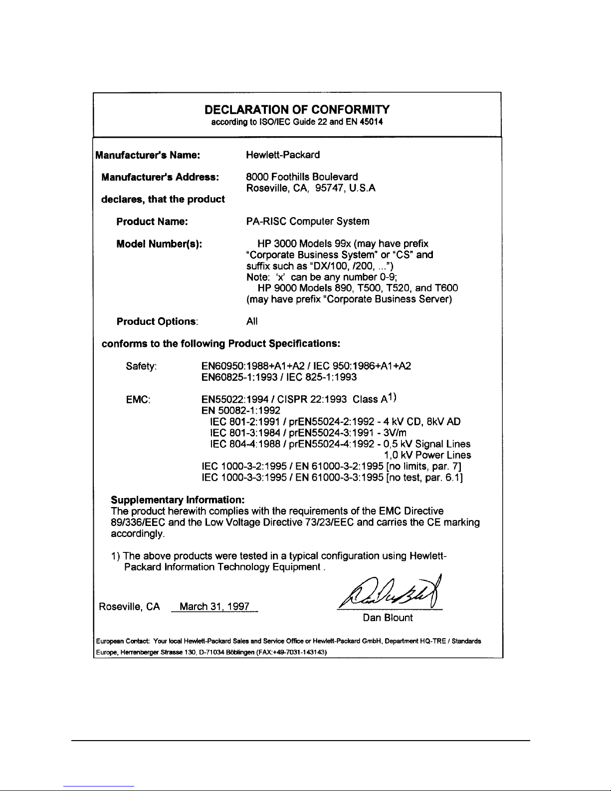
Safety and Regulatory Information
For your protection, this product has been tested to various national and international
regulations and standards. The scope of this regulatory testing includes
electrical/mechanical safety, radio frequency interference, ergonomic, acoustic, and
hazardous materials. Where required, approvals obtained from third-party test agencies
are shown on the product label. In addition, various regulatory bodies require some of the
information under the following headings.
USA Radio Frequency Interference
The United States Federal Communications Commission (in 47 CFR Subpart B , of P art 15)
has specified that the following notice be brought to the attention of the users of this
product:
WARNING This equipment has been tested and found to comply with the
limits for a Class A digital device, pursuant to Part 15 of the
FCC Rules. These limits are designed to provide reasonable
protection against harmful interference when the equipment is
operated in a commercial environment. This equipment
generates, uses, and can radiate radio frequency energy and, if
not installed and used in accordance with the instruction
manual, may cause harmful interference to radio
communications. Operation of this equipment in a residential
area is likely to cause harmful interference in which case the
user will be required to correct the interference at his own
expense.
Preface-3
Japanese Radio Frequency Interference
The following notice is for users of this product in Japan:
Japanese Radio Frequency Notice
EMI Statement (European Union Only)
This is a Class A product. In a domestic environment, this product may cause radio
interference in which case the user may be required to take adequate measures.
Digital Apparatus Statement (Canada)
This digital apparatus does not exceed the Class A limits for radio noise emissions from
digital apparatus as set out in the interference-causing equipment standard entitled
“Digital Apparatus”, ICES-003 of the Department of Communications.
Cet appareil numérique respecte les limites de bruits radioélectriques applicables aux
appareils numériques de Classe A prescrites dans la norme sur le matériel brouilleur :
“Appareils Numériques”, NMB-003 édictée par le ministre des Communications.
EMI (Australia and New Zealand)
Models HP3000 997 and HP9000 T600 meet the applicable requirements of the Australia
and New Zealand EMC Framework.
United Kingdom General Approval
The HP3000 99x and the HP9000 T-Class computers are approved under Approval No.
NS/G/1234/J/100003 for indirect connection to public telecommunication systems within
the United Kingdom.
Acoustics (Germany)
Laermangabe (Schalldruckpegel LpA) gemessen am fiktiver Arbeitsplatz bei normalem
Betrieb nach DIN 45635, Teil 19: L
A = 61 dB.
p
Acoustic Noise (A-weighted Sound Pressure Level L
position, normal operation, to ISO 7779: L
Preface-4
A = 61 dB.
p
A) measured at the bystander
p

Battery Notices
WARNING This product may contain sealed, lead acid batteries. Replace
only with the same type and part number. Recycle used
batteries or send them to the following address for disposal:
Hewlett Packard Co.
Environmental Health and Safety Department
8000 Foothills Boulevard
Roseville, Ca. 95678
ATTN: Battery Disposal Coordinator.
WARNING Fire, explosion, and severe burn hazard! Do not crush,
disassemble, heat, incinerate, or expose the batteries to water.
IT Power System
WARNING This product has not been evaluated for connection to an IT
power system (an AC distribution system having no direct
connection to earth according to IEC 950).
High Leakage Current
WARNING To reduce the risk of electric shock, never operate the product
with the ground conductor disconnected. An earth connection
is essential before connecting the supply. Reliable ground
circuit continuity is vital for safe operation of this product.
Preface-5
Installation Conditions (U.S.)
WARNING Please note the following conditions of installation:
An insulated earthing conductor that is identical in size,
insulation material, and thickness to the earthed and
unearthed branch-circuit supply conductors except that it is
green with or without one or more yellow stripes is to be
installed as part of the branch circuit that supplies the unit or
system. The earthing conductor described is to be connected to
earth at the service equipment or, if supplied by a separately
derived system, at the supply transformer or motor-generator
set.
The attachment-plug receptacles in the vicinity of the unit or
system are all to be of an earthing type, and the earthing
conductors serving these receptacles are to be connected to
earth at the service equipment.
Safety Considerations
This product and related documentation must be reviewed for familiarization with safety
markings and instructions before operation. The following figure shows some of the safety
symbols used on the product to indicate various safety considerations.
Safety Symbols
Instruction manual symbol: the product will be marked with this symbol
when it is necessary for the user to refer to the instruction manual in order to
protect the product against damage.
Indicates presence of electric shock hazard.
Indicates earth (ground) terminal (sometimes used in manual to indicate
circuit common connected to grounded chassis)
Indicates wiring terminal intended for connection of the protective earthing
conductor associated with the supply wiring.
Preface-6

WARNING The WARNING sign denotes a hazard. It calls attention to a
procedure, practice, or the like, which, if not done correctly or
adhered to, could result in injury. Do not proceed beyond a
WARNING sign until the indicated conditions are fully understood
and met.
CAUTION The CAUTION sign denotes a hazard. It calls attention to an operating
procedure, practice, or the like, which, if not done correctly or adhered
to, could damage or destroy part or all of the product. Do not proceed
beyond a CAUTION sign until the indicated conditions are fully
understood and met.
Preface-7
Preface-8

Preface
This edition of the Installation Guide is intended for experienced system operators.
This guide contains technical information about HP 3000 Corporate Business Systems
(99x Family) and HP 9000 Corporate Business Servers (T-Class System).
At the time of publication, HP 3000 Corporate Business Systems and HP 9000 Corporate
Business Servers included the following models:
HP 3000 99x Family
990/992 991/995 996
990CX
992/100CX
992/200CX
992/300CX
992/400CX
990DX
992/100DX
992/300DX
992/400DX
991CX
995/100CX
995/200CX
995/300CX
995/400CX
995/500CX
995/600CX
995/700CX
995/800CX
991DX
995/100DX
995/200DX
995/300DX
995/400DX
995/500DX
995/600DX
995/700DX
995/800DX
996/80
996/100
996/200
996/300
996/400
996/500
996/600
996/700
996/800
1
997/100
997/200
997/300
997/400
997/500
997/600
997/800
1. A 996 System may be field upgraded to 9, 10, 11, or 12 processors. F actory integrated servers are sold with a maximum of 8 processors.
HP 9000 T-Class Systems
890 T500 T520 T600
997
Preface-9

Preface-10

1 Introduction
Introduction
Chapter 1 1-1

Introduction
Overview
Overview
This guide provides installation and configuration procedures for the Hewlett-Packard
Precision Architecture-RISC (PA-RISC) systems listed in the Preface of this guide.
1-2 Chapter 1

Terminology
Terminology
The following terms are used in this document to refer to systems and components:
Term Refers to:
990 HP 3000 Systems (990/992)
991/995 HP 3000 Systems (991/995)
996 HP 3000 Systems (996)
997 HP 3000 Systems (997)
99x All HP 3000 990, 991, 992, 995, 996, 997 Systems
890 HP 9000 Servers (890)
T500 HP 9000 Servers (T500)
Introduction
T520 HP 9000 Servers (T520)
T600 HP 9000 Servers (T600)
T-Class Systems All HP 9000 890, T5x0, and T600 Servers
HP-HSC I/O Bus
Converter
HSC I/O cards High Speed Connect I/O cards (also know as
HP-PB I/O Bus
Converter
The bus converter motherboard on an 997/T600
System to which HSC I/O cards and HP-PB I/O Bus
Converters are attached.
General System Connect + (GSC+) cards)
Adapter card used to connect to internal and
external HP-PB card cages on 997/T600 Systems. It
has the same function on the 997/T600 System as
the Upper Bus Converter does on systems prior to
the 997/T600.
BC cards and HP-HSC I/O Bus Converters. On 997/T600 Systems, the HP-PB I/O Bus
Converter and the HP-HSC I/O Bus Converter together serve the same function as the upper
bus converter on 990/992/890, 991/995/T500, and 996/T520 Systems. The HP-PB I/O Bus
Converter is attached to the HP-HSC I/O Bus Converter.
The standard configurations for 99x/T-Class Systems differ slightly. Throughout this
manual, system-specific configurations will be noted where applicable (for example, as 99x
Systems Only or 890/T500 Systems Only).
Contents
This guide includes detailed information on the following subjects:
■ Safety and Environment Considerations
Chapter 1 1-3

Introduction
Terminology
■ Unpacking and Inspection
■ Processor Configuration
■ Power Supply Configuration
■ I/O Configuration
■ Initial Power Up and Selftest
Audience
Customers should read the information in Chapter 1 (Introduction) and Chapter 2
(Unpacking and Inspection).
HP Customer Engineers (CEs) and service personnel who have successfully completed
HP's authorized training should perform the procedures in Chapter 3 (Installation).
Site Preparation
Before the system can actually be installed, the system site must comply with the
specifications outlined in the 99x/T-Class Systems Site Preparation and Requirements
Guide (PN A1809-90002)
The service and installation requirements for any peripheral equipment to be installed
with the system should also be taken into consideration before the installation process gets
under way. Refer to the appropriate manual for each peripheral being installed.
Tools
The following tools are required for computer installation:
■ Standard hand tools
■ Digital Voltmeter (capable of reading AC/DC voltages)
■ #10 Torx-drive screwdriver
■ #15 Torx-drive screwdriver
Other References
Related manuals include:
■ CE Handbook (PN A1809-90003)
■ 99x/T-Class Systems Operator's Guide (PN A1809-90009)
■ 99x/T-Class Systems Site Preparation and Requirements Guide (PN A1809-90002)
■ 99x/T-Class Systems Expansion Cabinet Installation Guide (PN A1809-90006)
■ 99x/T-Class Systems HP-PB Cardcage Installation Guide (PN A1809-90013)
■ 99x/T-Class Systems Bus Converter Card Installation Guide (PN A1809-90012)
■ 99x/T-Class Systems Add-On Memory Installation Guide (PN A1809-90005)
1-4 Chapter 1

■ Upgrade Installation Guides
❏ Upgrading 990/992/890 to 991/995/T500 (PN A1820-90001)
❏ Upgrading 990/992/890 to 996 (PN A3310-90002)
❏ Upgrading 991/995/T500 to 996 (PN A3310-90001)
❏ Upgrading 991/995/T500 and 996/T520 to 997/T600 (PN A3329-90001)
❏ HP 3000 to HP 9000 Conversion Kit Ordering and Configuration Guide (PN
5964-9539E)
■ Diagnostic Media User's Guide (PN B6191-90001)
Introduction
Terminology
Chapter 1 1-5

Introduction
Safety and Environment Considerations
Safety and Environment Considerations
Before proceeding with any installation, maintenance, or service on a system which
requires physical contact with electrical or electronic components, be sure that either
power is removed or safety precautions are followed to protect against electric shock and
equipment damage. Observe all "WARNING" and "CAUTION" labels on equipment. All
installation and service work must be done by qualified personnel.
Communications Interference
Hewlett-Packard system compliance tests are conducted with Hewlett-Packard supported
peripheral devices and shielded cables, such as those received with the system. The system
meets interference requirements of all countries in which it is sold. These requirements
provide reasonable protection against interference with radio and television
communications.
Installing and using the system in strict accordance with Hewlett-Packard's instructions
minimizes the chances that the system will cause radio or television interference.
However, Hewlett-Packard does not guarantee that the system will not interfere with
radio and television reception.
Take these precautions:
■ Use only shielded cables.
■ Install and route the cables per the instructions provided.
■ Ensure that all cable connector screws are firmly tightened.
■ Use only Hewlett-Packard supported peripheral devices.
■ Ensure that all panels and cover plates are in place and secure before system operation.
Electrostatic Discharge
Hewlett-Packard systems and peripherals contain assemblies and components that are
sensitive to electrostatic discharge (ESD). Carefully observe the precautions and
recommended procedures in this manual to prevent component damage from static
electricity.
Take these precautions:
■ Always wear a grounded wrist strap when working on or around the system.
■ Treat all assemblies, components and interface connections as static-sensitive.
■ When unpacking cards, interfaces, and other accessories that are packaged separately
from the system, keep the accessories in their conductive plastic bags until they are
ready to be installed.
1-6 Chapter 1

Introduction
Safety and Environment Considerations
■ Before removing or replacing any components or installing any accessories in the
system, select a work area where potential static sources are minimized (preferably an
anti-static work station).
■ Avoid working in carpeted areas, and keep body movement to a minimum while
installing accessories.
Installation Environment
A special installation environment is not required as long as ESD considerations are
observed.
Chapter 1 1-7
Introduction
Orientation
Orientation
This section is a brief orientation to the SPU for 99x/T-Class Systems.
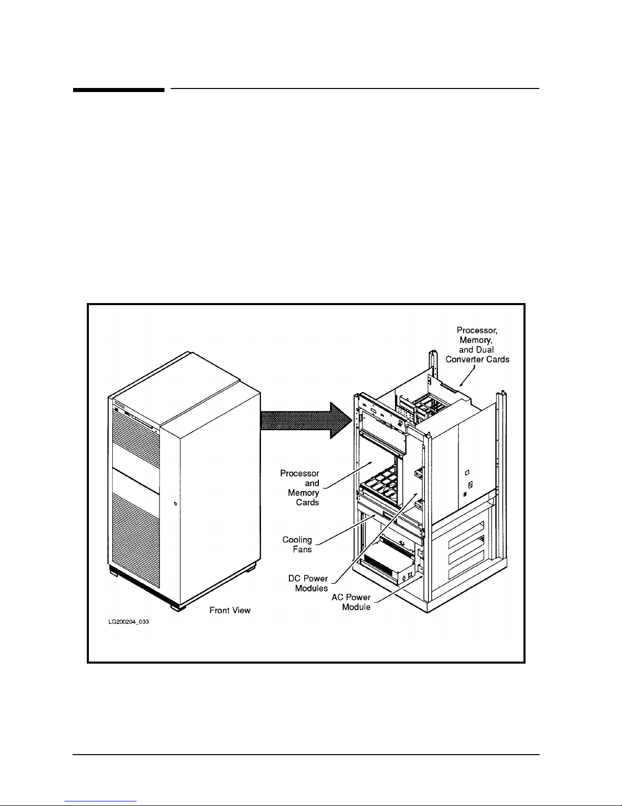
SPU Cabinet
The basic system consists of one SPU cabinet, as shown in Figure 1-1. At the middle right
of the cabinet is a cabinet door lock. To open the cabinet door, you insert a hexagonal
cabinet key into this lock and turn it counter-clockwise. The cabinet key is included with
the computer.
Additional cabinets (called expansion cabinets) are shipped separately. Refer to the
Expansion Cabinet Installation Guide (HP P/N A1809-90006) for information about
installing peripherals in the expansion cabinets.
Figure 1-1 SPU Cabinet
1-8 Chapter 1

Introduction
Orientation
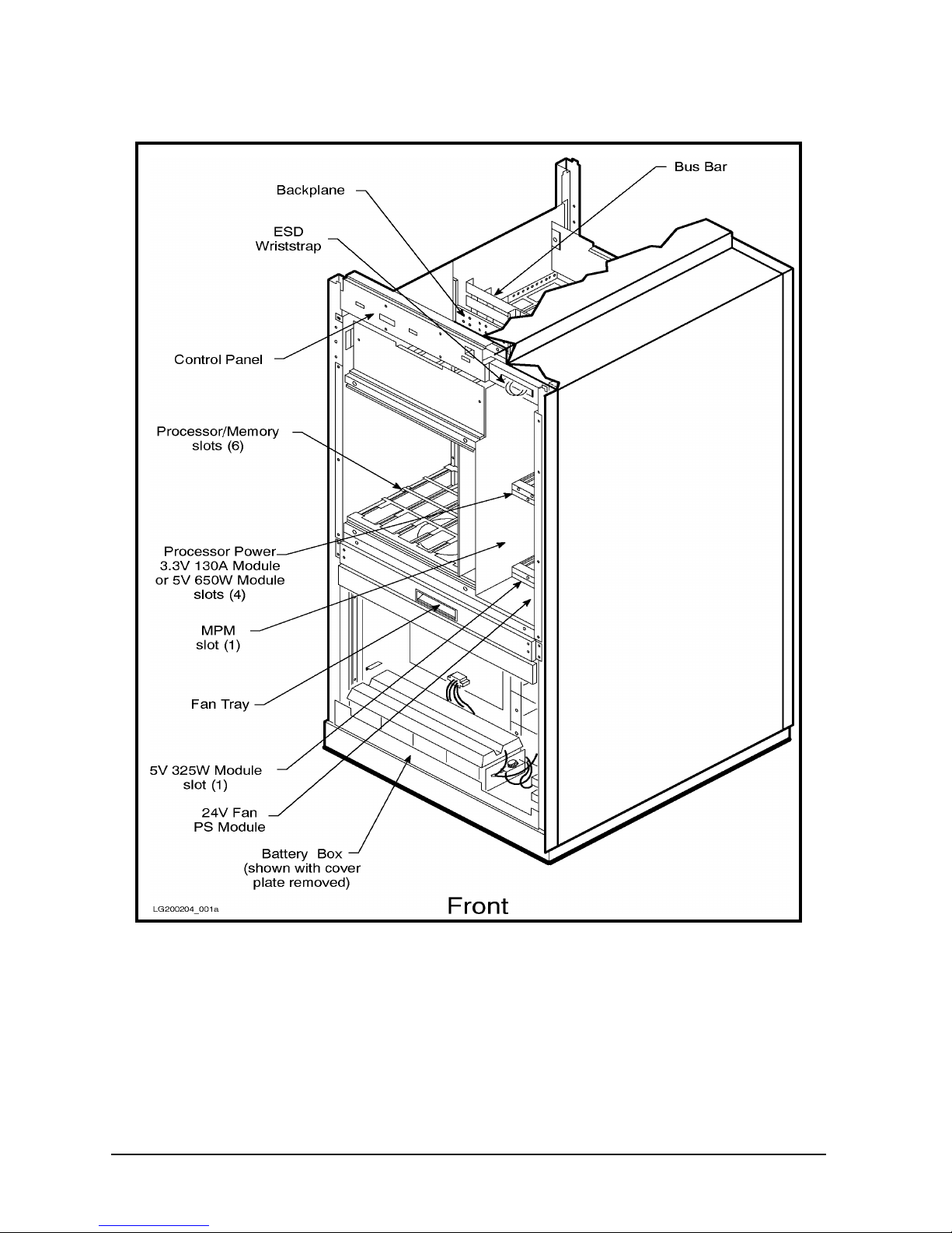
SPU Cabinet Internal Layout
The SPU cabinet contains the processor cards, memory cards, bus converter cards, I/O
cards, the power supply system, and the cooling fan assembly (see Figure 1-2 and Figure
1-3).
■ At the top front of the cabinet is the control panel, with various switches and indicators.
■ The top half of the cabinet contains:
❏ Processor Memory Bus (PMB) card cages. There is a front PMB card cage and a rear
PMB card cage. The PMB card cages contain processor cards, memory cards, bus
converter cards, and a service processor (SP) card.
❏ DC-to-DC power modules for memory, BC cards, processors, and fans.
❏ Miscellaneous Power Module (MPM) for the Service Processor.
■ In the middle of the cabinet is the cooling fan tray.
■ The bottom half of the cabinet contains:
❏ HP-PB card cage. This card cage accepts HP-PB I/O cards.
❏ AC-to-DC power module (PFC unit).
❏ AC Front End (ACFE) with the circuit breaker switch.
❏ Battery Back-up Unit (BBU) for 890, 990, and 992 only.
Chapter 1 1-9
Introduction
Orientation
Figure 1-2 SPU Cabinet Internal Layout (Front)
1-10 Chapter 1
 Loading...