

Page 1

System Memory Upgrade Guide
HP 3000/9x 9K S and H P 90 00/ Kxx0
Part No. A2375-90009
Printed in USA, January, 1998
Edition 6, E0198
Page 2

Legal Notices
The information containe d in this document is subject to change without notic e.
Hewlett-Packard makes no warranty of any kind with regard to this material, including, but not limited
to, the implied warranties of merchantability and fitness for a particul ar purpose. Hewlett-Packard sha ll
not be liable for errors cont ai ned herein or direct, indirect, special, incidental or consequential damages
in connection with the furni shing, performance, or use of this material.
Restricted Rights Legend.
restrictio ns as set forth in subparagraph (c) (1) (ii) of the Rights in Technic al Data and Computer
Software clause at DFARS 252.227- 7013 for DOD agencies, a nd subparagra phs (c) (1) and (c) (2) of the
Commercial Computer Software Restricted Rights clause at FAR 52.227-19 for other agencies.
HEWLETT-PACKARD COMPANY
3000 Hanover Street
Palo Alto, California 94304 U.S.A.
Reproduction, adaptation, or translation of this document without prior written per mission is prohibited,
except as allowed under the copyright laws.
Trademark Notices.
exclusively through X/Open Company Limited.
© Copyright 1983-1997 Hewlett-Packard Company, all rights reserved.
Use, duplication or disclosure by the U.S. Government is subject to
UNIX is a registered trademark in the United States and other countries, licensed
ii
Page 3

Printing History
New editions of this manual incorporate all material updated since the previous edition. The manual
printing date and part number indicate its current edition. The printing date changes when a new edition
is printed. (Minor corrections and updates which are incorporated at repr int do not cause the date to
change.) The manual part number changes when extensive technical changes are incorporated.
February 1995...............................................................................................................................Edition 1
September 1995 .......... .. ........... .. ........... .......... .............................................................................Edition 2
January 1996............................. .. ........... .......... .............................................................................Edition 3
June 1996......................................................................................................................................Edition 4
July 1997 .................... .......... ........................................................................................................Edition 5
January 1998 .......... ..................................................................................... .......... ............... ........Edition 6
Change Narrative
• Edition 6 technical chan ges include the addition of HP9000/K380/K580 information throughout the
manual.
• Minor changes and updates were also incorpor ated.
Reader Comments
Reader Comments. We welcome your comments about our documentation. If you have editorial
suggestions or recommend improvements for this document, please write to us. You can reach us
through e-mail at: hardwaredocs@cup.hp.com or by sending your letter to: Documentat ion Manager,
M/S 5657, Hewlett-Packard Company, 8000 Foothills Blvd., Roseville, CA 95747-5657 USA. Please
include the following infor mation in your message:
• Title of the ma nua l yo u are referencing.
• Manual part number (from the title page).
• Edition number or publicat ion dat e (from the title page).
• Your name.
• Your company’s name.
SERIOUS ERRORS, such as technical inaccuracies that may render a program or a hardware device
inoperative, should be reported to your HP Response Center or directly to a Support Engineer.
iii
Page 4

Preface
This edition of the HP 3000/9x9KS and HP 9000/Kxx0 System Memory Upgrade Guide contains
technical infor mation about the following models:
Model 939KS Model K100
Model 959KS Model K200
Model 969KS Model K400
Model 979KS Model K210
Model K210
Model K410
Model K220
Model K250
Model K260
Model K370
Model K380
Model K420
Model K450
Model K460
Model K570
Model K580
iv
Page 5

v
Page 6

Contents
1 HP 3000/9x9KS and HP 9000/K2x0/K4x0/Kx70/Kx80
Memory Upgrade Installation
Introduction . . . . . . . . . . . . . . . . . . . . . . . . . . . . . . . . . . . . . . . . . . . . . . . . . . . . . . . . . . . . . . . . . . . . . . . . .1-1
Contents of This Chapter . . . . . . . . . . . . . . . . . . . . . . . . . . . . . . . . . . . . . . . . . . . . . . . . . . . . . . . . . . . . .1-1
Required Tools . . . . . . . . . . . . . . . . . . . . . . . . . . . . . . . . . . . . . . . . . . . . . . . . . . . . . . . . . . . . . . . . . . . . .1-2
Installa tion Procedure (HP 3000/9x9KS and HP 9000/K2x0/K4x0/Kx70/Kx80). . . . . . . . . . . . . . . . . . . .1-3
Verifying the Current PDC Firmware . . . . . . . . . . . . . . . . . . . . . . . . . . . . . . . . . . . . . . . . . . . . . . . . . . .1-3
Obtaining the Correct Firmware Patch . . . . . . . . . . . . . . . . . . . . . . . . . . . . . . . . . . . . . . . . . . . . . . . . .1-4
Downloading the Firmware Patch via the World Wide Web . . . . . . . . . . . . . . . . . . . . . . . . . . . . .1-4
Downloading the Firmware Patch using FTP . . . . . . . . . . . . . . . . . . . . . . . . . . . . . . . . . . . . . . . . .1-4
Checking Existing System Memory . . . . . . . . . . . . . . . . . . . . . . . . . . . . . . . . . . . . . . . . . . . . . . . . . . . . .1-6
After Rebooting Your Sys tem, Type "ma" to Get the Main Menu . . . . . . . . . . . . . . . . . . . . . . . . . . .1-7
System Shutdown . . . . . . . . . . . . . . . . . . . . . . . . . . . . . . . . . . . . . . . . . . . . . . . . . . . . . . . . . . . . . . . . . . .1-8
Gaining Access to Memory . . . . . . . . . . . . . . . . . . . . . . . . . . . . . . . . . . . . . . . . . . . . . . . . . . . . . . . . . . .1-9
Memory Location on HP 3000/9x9KS and HP 9000/K2x0/K4x0/Kx70/Kx80 Servers . . . . . . . . . . .1-9
Removing the Front Bezel and Memory Bulkhead . . . . . . . . . . . . . . . . . . . . . . . . . . . . . . . . . . . . . . .1-9
Removing Memory Extenders . . . . . . . . . . . . . . . . . . . . . . . . . . . . . . . . . . . . . . . . . . . . . . . . . . . . . .1-10
Memory Configuration and SIMM Installation . . . . . . . . . . . . . . . . . . . . . . . . . . . . . . . . . . . . . . . . . . .1-12
Before You Begin . . . . . . . . . . . . . . . . . . . . . . . . . . . . . . . . . . . . . . . . . . . . . . . . . . . . . . . . . . . . . . . .1-12
Configuring Memory for Optimum Performance. . . . . . . . . . . . . . . . . . . . . . . . . . . . . . . . . . . . . . . .1-13
Memory Optimization Procedure for Single Memory Extenders — Overview. . . . . . . . . . . . . . . . .1-14
Procedure for Single Memory Extenders — Detailed . . . . . . . . . . . . . . . . . . . . . . . . . . . . . . . . . . . .1-15
Memory Optimization Procedure for Dual Memory Extenders — Overview . . . . . . . . . . . . . . . . . .1-18
Procedure for Dual Memory Extenders — Detailed . . . . . . . . . . . . . . . . . . . . . . . . . . . . . . . . . . . . .1-19
If You Still Get Warning Messages.... . . . . . . . . . . . . . . . . . . . . . . . . . . . . . . . . . . . . . . . . . . . . . . . .1-22
SIMM Removal and Installation . . . . . . . . . . . . . . . . . . . . . . . . . . . . . . . . . . . . . . . . . . . . . . . . . . . . . . . .1-25
Removing SIMMs. . . . . . . . . . . . . . . . . . . . . . . . . . . . . . . . . . . . . . . . . . . . . . . . . . . . . . . . . . . . . . . . . .1-25
Installing SIMMs . . . . . . . . . . . . . . . . . . . . . . . . . . . . . . . . . . . . . . . . . . . . . . . . . . . . . . . . . . . . . . . . . .1-25
After All SIMMs Are Installed. . . . . . . . . . . . . . . . . . . . . . . . . . . . . . . . . . . . . . . . . . . . . . . . . . . . . . . .1-27
System Reassembly . . . . . . . . . . . . . . . . . . . . . . . . . . . . . . . . . . . . . . . . . . . . . . . . . . . . . . . . . . . . . . . . . .1-28
Reinstalling Memory Extender(s). . . . . . . . . . . . . . . . . . . . . . . . . . . . . . . . . . . . . . . . . . . . . . . . . . . . . .1-28
Reattaching the Memory Bulkhead and Front Bezel . . . . . . . . . . . . . . . . . . . . . . . . . . . . . . . . . . . . . . .1-29
2 HP 9000/K100 Memory Upgrade Inst allation
Introduction . . . . . . . . . . . . . . . . . . . . . . . . . . . . . . . . . . . . . . . . . . . . . . . . . . . . . . . . . . . . . . . . . . . . . . . . .2-1
Contents of This Chapter . . . . . . . . . . . . . . . . . . . . . . . . . . . . . . . . . . . . . . . . . . . . . . . . . . . . . . . . . . . . .2-1
Electrostatic Discharge (ESD) Precautions . . . . . . . . . . . . . . . . . . . . . . . . . . . . . . . . . . . . . . . . . . . . . . .2-2
Required Tools . . . . . . . . . . . . . . . . . . . . . . . . . . . . . . . . . . . . . . . . . . . . . . . . . . . . . . . . . . . . . . . . . . . . .2-2
Installa tion Procedure (HP 9000/K100). . . . . . . . . . . . . . . . . . . . . . . . . . . . . . . . . . . . . . . . . . . . . . . . . . . .2-2
Checking Existing System Memory . . . . . . . . . . . . . . . . . . . . . . . . . . . . . . . . . . . . . . . . . . . . . . . . . . . . .2-2
Gaining Access to System Memory . . . . . . . . . . . . . . . . . . . . . . . . . . . . . . . . . . . . . . . . . . . . . . . . . . . . .2-5
Memory Location in HP 9000/K100 Servers. . . . . . . . . . . . . . . . . . . . . . . . . . . . . . . . . . . . . . . . . . . .2-5
Removing the Memory Bulkhead. . . . . . . . . . . . . . . . . . . . . . . . . . . . . . . . . . . . . . . . . . . . . . . . . . . . .2-5
Memory Configuration and SIMM Installation . . . . . . . . . . . . . . . . . . . . . . . . . . . . . . . . . . . . . . . . . . . .2-6
Configuring Memory . . . . . . . . . . . . . . . . . . . . . . . . . . . . . . . . . . . . . . . . . . . . . . . . . . . . . . . . . . . . . .2-6
Memory SIMM Rules . . . . . . . . . . . . . . . . . . . . . . . . . . . . . . . . . . . . . . . . . . . . . . . . . . . . . . . . . . . . . . . .2-6
Removing SIMMs. . . . . . . . . . . . . . . . . . . . . . . . . . . . . . . . . . . . . . . . . . . . . . . . . . . . . . . . . . . . . . . . .2-7
Installing SIMMs (HP 9000/K100) . . . . . . . . . . . . . . . . . . . . . . . . . . . . . . . . . . . . . . . . . . . . . . . . . . . . .2-8
Orient the SIMMs Correctly. . . . . . . . . . . . . . . . . . . . . . . . . . . . . . . . . . . . . . . . . . . . . . . . . . . . . . . . .2-8
v
Page 7

Contents
After All SIMMs Are Ins talled. . . . . . . . . . . . . . . . . . . . . . . . . . . . . . . . . . . . . . . . . . . . . . . . . . . . . . . .2-10
Reattach the Memory Bulkhead . . . . . . . . . . . . . . . . . . . . . . . . . . . . . . . . . . . . . . . . . . . . . . . . . . . . .2-10
3 Power On and Verification
Power On . . . . . . . . . . . . . . . . . . . . . . . . . . . . . . . . . . . . . . . . . . . . . . . . . . . . . . . . . . . . . . . . . . . . . . . . . . .3-1
If There Is a Problem at Power On . . . . . . . . . . . . . . . . . . . . . . . . . . . . . . . . . . . . . . . . . . . . . . . . . . . . . .3-1
Installa tion Verification . . . . . . . . . . . . . . . . . . . . . . . . . . . . . . . . . . . . . . . . . . . . . . . . . . . . . . . . . . . . . . . .3-2
If There Is a Problem Verifying the Installat ion. . . . . . . . . . . . . . . . . . . . . . . . . . . . . . . . . . . . . . . . . . . .3-2
Possible Causes. . . . . . . . . . . . . . . . . . . . . . . . . . . . . . . . . . . . . . . . . . . . . . . . . . . . . . . . . . . . . . . . . . .3-3
Memory Error Codes and Warning Messages . . . . . . . . . . . . . . . . . . . . . . . . . . . . . . . . . . . . . . . . . . . . .3-3
Memory Error Codes . . . . . . . . . . . . . . . . . . . . . . . . . . . . . . . . . . . . . . . . . . . . . . . . . . . . . . . . . . . . . .3-3
Consol e W arn i n g M essages . . . . . . . . . . . . . . . . . . . . . . . . . . . . . . . . . . . . . . . . . . . . . . . . . . . . . . . . .3-5
Appendix A: OS Requirements and Diagnostic Support for Memory Modules
OS Requirements for 64MB, 256MB, and 512 MB Modules . . . . . . . . . . . . . . . . . . . . . . . . . . . . . . . . . . A-1
Obtaining Software Patches for HP-UX Operating Systems. . . . . . . . . . . . . . . . . . . . . . . . . . . . . . . . . . . A-2
How to subscribe to HP Support Line Patch notifications: . . . . . . . . . . . . . . . . . . . . . . . . . . . . . . . . . . . A-2
Electronic Mail. . . . . . . . . . . . . . . . . . . . . . . . . . . . . . . . . . . . . . . . . . . . . . . . . . . . . . . . . . . . . . . . . . A-2
World Wide Web . . . . . . . . . . . . . . . . . . . . . . . . . . . . . . . . . . . . . . . . . . . . . . . . . . . . . . . . . . . . . . . . A-2
vi
Page 8

Contents
vii
Page 9

1
HP 3000/9x9KS and HP 9000/K2x0/K4x0/Kx70/Kx80
Memory Upgrade Installation
Introduction
This guide contains memory upgrade inst al lation procedures for HP 3000/9x9KS and HP 9000/Kxx0
computers. The guide is organized as follows:
• Chapter 1: HP 3000/9x9KS and HP 9000/K2x0/K4x0/Kx70 /Kx80 Memory Upgrade Installation
• Chapter 2: HP 9000/K100 Memory Upgrade Installation
• Chapter 3: Power On and Verification
If you have an HP 9000/K100 server, refer to Chapter 2 of this guide for memory upgrade installation
procedures appropriate to that server.
Contents of This Chapter
This chapter describes memory upgrade installation on HP 3000/K9x9KS and HP
9000/K2x0/K4x0/Kx70/Kx80 comput ers:
• Verifying the current PDC
• Checking Existing System Memory
• System Shutdown
• Gaining Access to Memory
• Memory Configuration
• Memory SIMM Installation
• System Reassembly
1-1
Page 10

HP 3000/9x9KS and HP 9000/K2x0/K4x0/Kx70/Kx80 Memory Upgrade Installation
Introduction
Electrostatic Discharge (ESD) Precautions. When performing the upgrade procedures in this guide,
you must observe the following antistatic precautions to prevent da mage to memory boards and system
components from electrostatic discharge. An ESD kit (HP P/N A3024-80004) is supplied with your
memory upgrade kit. This ESD kit contains one wrist strap, one conductive sheet, and one anti-static
foam pad.
• Always wear a grounded wrist strap when working on or around the system, and when handling
printed circuit boards.
• Treat all assemblie s, components, and interface connections as static-sensitive.
• Perform all rem ov al and in stal lat i on in a wo rk area wh ere potential static sources are minimized
(preferably an anti-static work station).
• Avoid working in carpete d areas, and keep body movement to a minimum while removing and
installing boards to minimiz e buil dup of static charge.
Required Tools
• One #10 Torx driver (preferred tool)
• One small flat-blade screwdriver (if Torx driver is not available)
1-2 Chapter 1
Page 11

HP 3000/9x9KS and HP 9000/K2x0/K4x0/Kx70/K x80 Memory Upgrade Installation
Installation Procedure (HP 3000/9x9KS and HP 9000/K2x0 /K4x 0/Kx70/Kx80)
Installation Procedure (HP 3000/9x9KS and HP
9000/K2x0/K4x0/Kx70/Kx80)
Verifying the Current PDC Firmware
If you are planning to install 64MB, 128MB, 256MB, or 512 MB Memory Modules, you may need to
verify your system’s PDC firmware version to see if it supports that type of memory (see “OS
Requirements and Diagnostic Supp ort for 64 MB and 256 MB Modules” on page A-1). If you need to
upgrade your PDC, see the section entitle d "Obtaining the Correct Firmware Patch."
Using On-Line Diagnostics: (If on-line diagnostics are not present on your system, use the Boot
Console Handler procedure to verify the current version.)
1. At the system prompt, enter sysdiag.
2. At the sysdiag prompt, enter sysmap.
3. At the sysmap prompt, enter cpumap.
The output of cpumap will display the current PDC revision (See Table A-1, Appendix A).
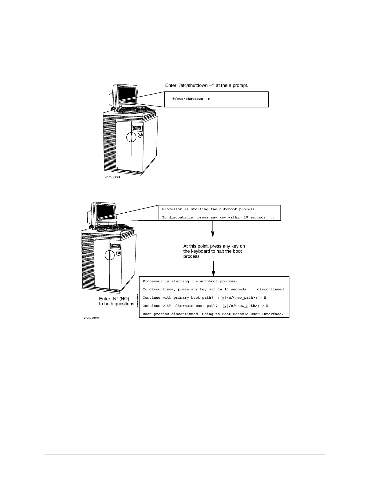
Using the Boot Console Handler:
1. Log on as root, and enter reboot -r. This command will shut down the operating system and reboot
the system.
2. If AUTOBOOT is on, you will receive the following message:
Process is starting autoboot process.
To discontinue, press any key within 10 seconds.
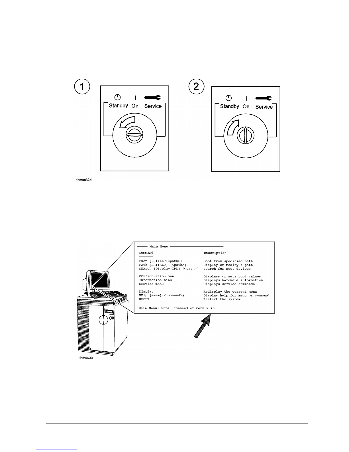
3. At this point, press any key within 10 seconds to interrupt the booting proc ess .
4. The Main Menu is displayed. A prompt will appear as
MAIN MENU: Enter command or menu>
5. Enter the command in.
Chapter 1 1-3
Page 12

HP 3000/9x9KS and HP 9000/K2x0/K4x0/Kx70/Kx80 Memory Upgrade Installation
Installation Procedure (HP 3000/9x9KS and HP 9000/K2x0/K4x0/Kx70/ Kx80)
6. A prompt will appear as:
Information Menu: Enter Command>
7. Enter the command fv.
The system will respond with the current firmware revision (See Table A-1, Appendix A).
Obtaining the Correct Firmware Patch
The firmware patches for all K-Class and HP3000 9x9/KS systems can obtained from the HPESC (HP
Electronic Support Center) via the World Wide Web or via FTP.
Downloading the Firmware Patch via the World Wide Web
To access and download the appropriate patch, perform the following steps:
1. Connect to the HPESC World Wide Web servi ce home page a t their URL by entering the following:
http://us-support.external.hp.com
2. Under Support Line , select the Patch Database option.
3. If you are a previously registered user:
a. Click on “Enter as a Registered User” and select your region.
b. Login, entering your User ID and password. This will take you to the Patch Database Main
screen.
If you are a first-t ime user:
a. Click on your geographic region under “Register Now”.
b. Review the “Terms and Conditions” page. At the bottom of the page you may accept the terms
and conditions and proceed to the registr ation page.
c. Complete the registration information requested.
d. Once the registr ation information has be en successfully transmitted, the User ID Assigned screen
will appear. Write down the User ID (or print the scree n) for later reference.
e. Click on “Begin Using Patch Database Now” to proceed to the Patch Database Main screen.
4. Select the Firmware Patches option.
5. Select the CPU Patches option and click on “Show Patches”.
6. Choose the a ppropriate patch (for example, ( PF_CKHK0022). A patch description will appear. Click
on “download” to copy the patch to your system.
NOTE
The selected patch must be downloaded from HP SupportLine onto a system that has
HP-UX as the operating system.
7. Follow the instructions in the
Downloading the Firmware Patch using FTP
1. Connect to HPESC via ftp. You must initiate downloading from an open subnet system as:
1-4 Chapter 1
Readme
file to create a bootable tape and to update PDC.
Page 13

HP 3000/9x9KS and HP 9000/K2x0/K4x0/Kx70/K x80 Memory Upgrade Installation
Installation Procedure (HP 3000/9x9KS and HP 9000/K2x0 /K4x 0/Kx70/Kx80)
>ftp us-support.external.hp.com
(If you do not have an open subnet system, try using rftp instead of ftp.)
2. Login as “anonymous”.
3. At the
Password prompt, enter your e-mail address as the passwor d.
4. Change to the directory conta ining the firmware patches:
> cd firmware_patches/hp/cpu
If desired, review the contents of the dire ct ory by using the ls command. For each patch, there is an
accompanying text file (patchfilename.txt). The text file contains the patch description and the
instructions for creating the patch tape.
5. Download the appropriate patch file and text file:
get <patc hf il en am e>
get <patc hf il en am e> .t xt
Chapter 1 1-5
Page 14
HP 3000/9x9KS and HP 9000/K2x0/K4x0/Kx70/Kx80 Memory Upgrade Installation
Installation Procedure (HP 3000/9x9KS and HP 9000/K2x0/K4x0/Kx70/ Kx80)
Checking Existing System Memory
If You Have an HP 9000/K2x0/K4x0/Kx70/Kx80, Reboot the System
Then, Halt the Boot Process
1-6 Chapter 1
Page 15
HP 3000/9x9KS and HP 9000/K2x0/K4x0/Kx70/Kx80 Memory Upgrade Installation
Installation Procedure (HP 3000/9x9KS and HP 9000/K2x0 /K4x 0/Kx70/Kx 80)
If You Have an HP 3000/9x9KS, First Shut Down the Operating
System. Then, After "DA00" Appears on the LCD Display, Turn key to
Standby and Back On
After Rebooting Your System, Type "ma" to Get the Main Menu
After rebooting your HP 9000/K2x0/K4x0/Kx70/Kx80 or HP 3000/9x9KS system, the Boot Console
Interface prompt (PDC>) should appear on your conso le dis play. Type ma at the prompt to get to the
Main menu, then proceed to the steps on the following page to check existing system memory.
Type "in" at the Main Menu to Get to the Information Menu
Chapter 1 1-7
Page 16

HP 3000/9x9KS and HP 9000/K2x0/K4x0/Kx70/Kx80 Memory Upgrade Installation
Installation Procedure (HP 3000/9x9KS and HP 9000/K2x0/K4x0/Kx70/Kx80)
Type "me" at the Information Menu to Check Memory
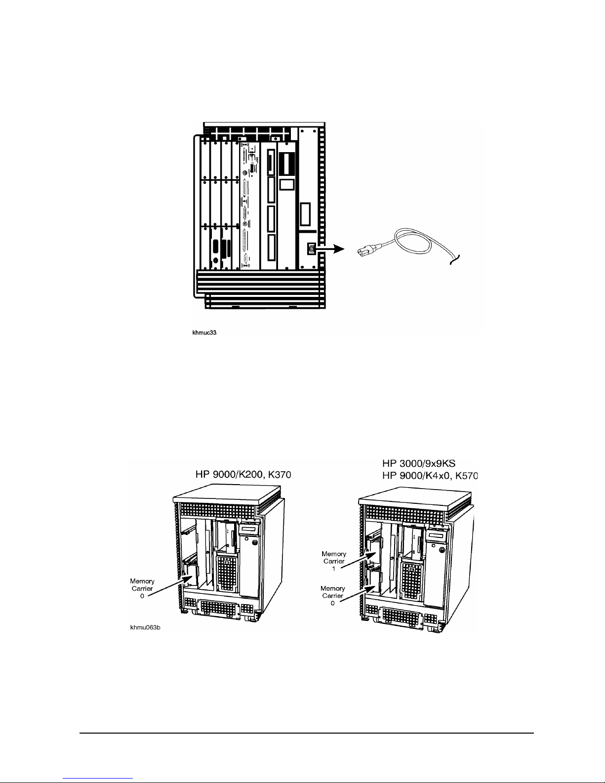
System Shutdown
Turn the system key switch to “Standby” (fully counterclockwise)
1-8 Chapter 1
Page 17
HP 3000/9x9KS and HP 9000/K2x0/K4x0/Kx70/Kx80 Memory Upgrade Installation
Installation Procedure (HP 3000/9x9KS and HP 9000/K2x0 /K4x 0/Kx70/Kx 80)
Disconnect the syste m power cable from the back of the system
cabinet
Gaining Access to Memory
Memory Location on HP 3000/9x9KS and HP 9000/K2x0/K4x0/Kx70/Kx80 Servers
In these models, the SIMMs are inserted into memory extenders (also called carriers) that attach to the
front of the system board, and are accessible from the front of the system. The HP 3000/9x9KS and HP
9000/K4x0 each have two memory extenders, and the HP 9000/K2x0 has one (see figure below).
Removing the Front B ezel and Memo ry Bulkhead
1. Remove the front bezel by gently pulling the bottom of the bezel forward and lifting upward, then
disengaging the top of the bezel from a hidden hinge. The front of the SPU is now accessible.
Chapter 1 1-9
Page 18

HP 3000/9x9KS and HP 9000/K2x0/K4x0/Kx70/Kx80 Memory Upgrade Installation
Installation Procedure (HP 3000/9x9KS and HP 9000/K2x0/K4x0/Kx70/Kx80)
2. Remove the memory bulkhead by loosening the six captive screws with a Torx driver.
Removing Memory Extenders
NOTE
1. Attach an antistatic device to your wrist and ground it to the system chassis.
2. Pull gently on the memory extende r ring to unse at the extender connector from the system board.
3. Pull the memory extender out of the system and place it on an antistatic mat.
1-10 Chapter 1
To prevent damage to memory boards and system components from electrostatic
discharge, always wear a ground ed wrist strap when working on or around the system,
and when handling printed circuit boards.
Page 19

HP 3000/9x9KS and HP 9000/K2x0/K4x0/Kx70/Kx80 Memory Upgrade Installation
Installation Procedure (HP 3000/9x9KS and HP 9000/K2x0 /K4x 0/Kx70/Kx 80)
Chapter 1 1-11
Page 20

HP 3000/9x9KS and HP 9000/K2x0/K4x0/Kx70/Kx80 Memory Upgrade Installation
Installation Procedure (HP 3000/9x9KS and HP 9000/K2x0/K4x0/Kx70/Kx80)
Memory Configuration and SIMM Installation
Memory in HP 3000 and HP 9000 servers can be added in many different megabyte combinations
depending on your model, your use of existi ng memory, your memory upgrade goals, and what
combination of memory modules you inst all .
NOTE
Regardless of the availability of SIMM slots, the total amount of memory you can install
is dependent on your system model and your operating system. Refer to your system
Owner’s Guide.
The configuration guide lines presented in this chapter will suc cessfully optimize most combinations of
memory modules. It is still possible, however, when adding memory to already-configured memory on
two extenders, to meet these guidelines and still generate a warning that your memory is not optimized.
If that happens, remove all memory modules from both extenders and re-inst all them following the
guidelines provide d below.
Before You Begin
Before you begin, you should understand the following definitions:
A SIMM is a single memory Printed Circuit Assembly (PCA) or memory board. SIMMs have memory
on one side of the PCA only. All SIMMs have their size marked on the board near the upper left corner.
A DIMM is a single memory PCA with memory on both sides of the PCA. All DIMMs have their size
marked on the board near the upper left corner, also.
NOTE
The acronym SIMM is used throughout this document to indic ate either SIMM or
DIMM.
A module is a pair of SIMMs or DIMMs. Memory for your system is purchased and installed only in
modules; never install just one SIMM.
A pair of modules is four SIMM cards.
1-12 Chapter 1
Page 21

HP 3000/9x9KS and HP 9000/K2x0/K4x0/Kx70/Kx80 Memory Upgrade Installation
Installation Procedure (HP 3000/9x9KS and HP 9000/K2x0 /K4x 0/Kx70/Kx 80)
256MB SIMM + 256MB SIMM = one 512MB module
a
128MB SIMM + 128MB SIMM = one 256MB
64MB SIMM + 64MB SIMM = one 128MB module
module
32MB SIMM + 32MB SIMM =
16MB SIMM + 16MB SIMM = one 32MB module
A set of 2 same-size SIMMs = 1 module
A set of 4 same-size SIMMs = 1 pair of modules
one 64MB
a
modu le
a. See “OS Requirements a nd Diagnostic Support f or 64MB, 256MB,
and 512MB Modules” on page A-1.
Confi guring Memory for Optimum Perfor mance
For OPTIMUM memory performance, memory must be installed in a particular slot sequence. This
section provides an overvie w and then detailed procedures for both single- and dual -extender systems.
If your memory is not configured for optimum performan ce, the warning, Memory not optimized for
performance, appears when you boot the system. Your memory will still work, but your system’s
performance may be degraded.
On HP3000/979KS and HP9000/K250/K260/K450/K460/Kx70/Kx80 systems, non-optimized memory
has another impact. The fi rmware include s a new use r-conf igurable fla g calle d auto star t. I f the flag is se t
to OFF, the selftest will detect the performanc e degradatio n when you boot and will inhibit autoboot a nd
autosearch. If you’re not sure whet her a warni ng was displayed (i.e., warnings may have scroll ed off
your console), you can re- display any warning messages. From the Information menu in the user
interface, use the warn command to see any warning messages that came up during the boot.
If you get the warn ing, Memory not optimiz ed, use t he me command in the Informati on Menu of t he user
interface (t he Bo o t Console Handler) to check your memory configuration. This command will not
directly tell you whether your memory is installed for optimum performance; it will only tell you
whether the module s are seated c orrectly and re co gnized as part of your system con figuration. However,
you can review the sequence of memory modules in the memory extende rs. The most importa nt memory
optimization rule is that all module pairs of each memory size should be installed in lower-numbered
slots before any modules pairs (see the proc edures and examples on pages 1-13 through 1-20). If the
display of your memory configur ation shows any sing le modules inst al led before module pairs , you will
need to reconfigure your memory using those procedures.
If the warning Memory not optimized does not appear, your m emor y is at optimum configura tion.
Chapter 1 1-13
Page 22

HP 3000/9x9KS and HP 9000/K2x0/K4x0/Kx70/Kx80 Memory Upgrade Installation
Installation Procedure (HP 3000/9x9KS and HP 9000/K2x0/K4x0/Kx70/ Kx80)
Memory Optimization Procedure for Single Memory Extenders — Overview
CAUTION
Module Installation is a 6-step process
1. Remove any currently insta lled memory modules.
2. Combine the removed and new memory modules and organize them into four groups:
• 512 MB modules
• 256 MB modules
• 128MB modules and 64MB modules (combined in the same group)
• 32MB modules
3. Divide each group into pairs of modules (4 SIMMs) and single modules (2 SIMMs), if any.
4. Identify each slot by its slot num ber and letter (0a, 0b, 1a, 1b, and so on) on the extender.
5. Install any pairs of modules as follows:
A. Install from largest to smallest memory size.
To prevent damage to memory boards and system components from electrostatic
discharge, always wear a ground ed wrist strap when working on or around the system,
and when handling printed circuit boards.
B. Install from lowest numbered to highest number slots.
6. When all pairs of modules have been installed, install any remaining old or new modules:
A. Install from largest to smallest memory size.
B. Install from lowest numbered available slots to highest number slots.
NOTE
NOTE
512MB Memory Modules are only supported on Kx70/Kx80 systems.
Kx70/Kx80 systems with four to six CPUs that use the minimum 256MB memory size
REQUIRE that the memory consist of at least four SIMMs (two modules).
1-14 Chapter 1
Page 23

HP 3000/9x9KS and HP 9000/K2x0/K4x0/Kx70/K x80 Memory Upgrade Installation
Installation Procedure (HP 3000/9x9KS and HP 9000/K2x0 /K4x 0/Kx70/Kx80)
Procedure for Single Memory Extenders — Detailed
Step 1. Remove any modules pa irs from the memory extender.
Step 2. Combine the removed and new memory modules and organize them into four groups:
• 512MB modules
• 256MB modules
• 128MB and 64MB modules (combined in the same group)
• 32MB mo dule s
NOTE
Even though 128MB modules and 64MB modules are in the same group, the SIMMs for
each module size cannot be mixed, i.e., do not combine a 64MB SIMM and a 32MB
SIMM as one module.
Step 3. From eac h memory group, create as many pairs of modules (sets of 4 SIMMs) as possible. A
128MB module and a 64MB module can be used as a pair of modules since they are from the
same group. Set aside any remaining modules of each size for installation last. Remember,
each module consists of 2 same-size SIMMs. Any remaini ng single SIMMs are "unusable."
Step 4. Locat e and identify each available slot by its slot number and letter (e.g., 0a, 0b) on the
memory extender. Identify the sequence of available slots from lowest to highest.
Step 5. Install any pairs of module s (sets of 2 modules) first.
A. Install pairs of modules in decreasing size: start with the largest memory size and end with the
smallest. Within a mixed-group of 128MB and 64MB modules, install the 128MB modules first.
B. Install pairs of modules beginning with the lowest available slot number, then the next higher slot
number. In an empty extender, for example, the first pair of modules will go in slots 0a/0b and
1a/1b; the next in 2a/2b and 3a/3b, and so on.
Step 6. Install any remaining modules, starting with the largest memory size first.
Chapter 1 1-15
Page 24

HP 3000/9x9KS and HP 9000/K2x0/K4x0/Kx70/Kx80 Memory Upgrade Installation
Installation Procedure (HP 3000/9x9KS and HP 9000/K2x0/K4x0/Kx70/ Kx80)
Example — Installing New Memory in an Empty Extender
1. Four 128MB SIMMs = Two 256MB modules
(one pair of 256MB modules)
2. Six 64MB SIMMs
and two 32MB SIMMs
= Three 128MB modules and one 64MB modul e
(2 pairs of 128MB/64MB modules)
3. Two 16MB SIMMs = One 32MB module
Install. Order Slots Memory
First pair of modules
0a/0b 256MB module
1a/1b 256MB module
Second pair of modules
2a/2b 128MB module
3a/3b 128MB module
Third pair of modules
4a/4b 128MB module
5a/5b 64MB module
Remaining
6a/6b 32MB module
module
7a/7b empty
Shaded boxes indicate pairs of modules
1-16 Chapter 1
Page 25

HP 3000/9x9KS and HP 9000/K2x0/K4x0/Kx70/Kx80 Memory Upgrade Installation
Installation Procedure (HP 3000/9x9KS and HP 9000/K2x0 /K4x 0/Kx70/Kx 80)
Example — Adding Memory to a Single Extender with Existing Memory
CURRENT MEMORY: (3) 128 MB and (2) 64MB pairs of modules
TO BE ADDED: (1) 256MB, (1) 128MB, and (1) 32MB pairs of modules
BEFORE AFTER
Memory
Modules
Slots
Memory
Modules
1. Remove the single 64MB module from slot 3a/3b.
Slots
2. Combine the removed module and the new modules into
0a/0b 128MB 0a/0b 128MB
1a/1b 128MB 1a/1b 128MB
128MB 2a/2b 2a/2b 128MB
groups:
one 256MB module
one 128MB module and one 64MB modu le
(one pair of modules)
one 32MB module
3a/3b 64MB 3a/3b 128MB
4a/4b 64MB
5a/5b empty
3. Add the largest pai r of modules (the only quad is the
128MB/64MB module) to the lowest available slots (4a/4b and
5a/5b.
4. Add the 256MB module to the next slot.
4a/4b 64MB
5a/5b 64MB
5. Add the 32MB modulemodule to the next slot.
6a/6b empty 6a/6b 256MB
7a/7b empty 7a/7b 32MB
Shaded boxes indicate pairs of modules
Chapter 1 1-17
Page 26

HP 3000/9x9KS and HP 9000/K2x0/K4x0/Kx70/Kx80 Memory Upgrade Installation
Installation Procedure (HP 3000/9x9KS and HP 9000/K2x0/K4x0/Kx70/Kx80)
Memory Optimization Procedure for Dual Memory Extenders — Overview
Module installati on is a 6-step process:
1. Remove any currently insta lled pairs of memory modules.
2. Combine the removed and newpairs of memory modules and organize them into four groups:
• 512 MB modules
• 256 MB modules
• 128MB and 64MB modules (combined in the same group)
• 32MB modules
3. Divide each group into pairs of modules (4 SIMMs) and pairs of modules, if any.
4. Identify each availa ble slot by its slot number and letter (e.g., 0a, 0b, 1a , 1b and so for th) on each
memory extender.
5. Install any pairs of modules as follows:
A. Install from largest to smallest memory size.
B. Install memory by alternating pairs of modules between extenders.
C. Inst al l from l owest num bered availabl e slots to highest number sl ots on the e xtender wit h the most
slots available .
6. Install any remaining modules (2 SIMMs), filling in the lowest-numbered slots on the extender with
the most available slots.
NOTE
In the examples that follow, the extenders are labeled "first extende r" and "second
extender." It is also useful to refer to these as "Extender 0" and "Extender 1",
corresponding to the lower an d upper ext ender slots in the system memory bay.
NOTE
Adding A Memory Extender
If you are adding a new memory extender at the same time you are adding memory, you
will likely need to remove and re-se que nce all the memory modules from your current
memory extender. Review these opti mization procedures for dual memory extend ers to
understand the need for balancing pairs of memory modules across the two extenders.
1-18 Chapter 1
Page 27

HP 3000/9x9KS and HP 9000/K2x0/K4x0/Kx70/K x80 Memory Upgrade Installation
Installation Procedure (HP 3000/9x9KS and HP 9000/K2x0 /K4x 0/Kx70/Kx80)
Procedure for Dual Memory Extenders — Detailed
Step 1. You must remove any modules from each memory extender.
If you have only one pair of memory modules in your system, and that pair has been
split across the t wo memory extenders, you will get a "Memory not optimized" warning
when you boot your system. Remove the module from one extender and add it to the
module on the other extender (see Step 5 below).
Step 2. Combine the removed and new memory modules and organize them into four groups:
• 512 MB modules
• 256 MB modules
• 128MB and 64MB modules (combined in the same group)
• 32MB modules.
Step 3. From each memory gro up, create as man y pa irs o f modul es (sets of 2 modules, or 4 SIMMs)
as possible. A 128MB and 64MB module can be used as a pair of modules since they ar e from
the same group. Set aside any remaining modules of each size for installation last.
Remember, each module consists of 2 same-siz e SIMMs. Any remai ning single SIMMs are
"unusable."
Step 4. Locat e and identify each available slot by its slot number and letter (e.g., 0a, 0b) on each
memory extender. Identify the sequence of slots from lowest to highest
Step 5. Instal l any pairs of modules first as follows:
A. Install modules in decreas ing siz e: start with the largest memory size and end with the smallest.
Within a mixed-group of 128MB and 64MB modules, install the 128MB modules first.
B. Install pairs of modules beginning with the lowe st available slot number on the extender with the
most slots open.
If both extenders are empty, the fi rst pair of module would go in slots 0a/0b and 1a/1b on the first
extender; the second pai r of modules would go in slots 0a/0b and 1a/1b on the second extender; the
next pair of modules would go in slots 2a/2b and 3a/3b on the first extender, and so on.
Install all pairs of modules before installing modules.
Step 6. Insta ll any remaining modules, beginning with the large st memory size, filling in the lowest
available slot numbers on the exte nde r with the most slots available.
Chapter 1 1-19
Page 28

HP 3000/9x9KS and HP 9000/K2x0/K4x0/Kx70/Kx80 Memory Upgrade Installation
Installation Procedure (HP 3000/9x9KS and HP 9000/K2x0/K4x0/Kx70/ Kx80)
Example - Installing new memory to two empty extenders
1. 14 128MB SIMMs = Seven 256MB mo dules (three pairs of modules and one 256MB
module)
2. 6 64MB SIMMs
and 2 32MB SIMMs
3. 6 16MB SIMMs = Three 32MB modules (one pa ir of 32MB mo dules and one
= Three 128MB modules and one 64MB module
(two pairs of 128MB/64MB modules)
32MB module)
1. Start with the pairs of largest memory (three pairs of 256MB modules):
• First pair in first exte nder (Extender 0), slots 0a/0b and 1a/1b.
• Second pair in second extender (Extender 1), slots 0a/0b and 1a/1b.
• Third pair in first extender, slots 2a/2b and 3a/3b.
2. Now install the pairs of next- largest memory (two pairs of 128MB/64MB modules):
• First pair in the lowes t slots of the extender with the most available slots: Second extender, 2a/2b
and 3a/3b.
• Second pair in the first extender, slots 4a/4b and 5a/5b.
3. Now install the pairs of the next-la rgest memory (one pair of 32MB modules) in the lowest slots of
the extender with the most available slots, then install the largest modul e (256MB) in the next slot in
sequence: first extend er, slots 6a/6b.
4. Now install the last modul e (32MB) in the next slot in sequence: second extender, slots 6a/6b.
First Extender Second Extender
Install. Order Slots - Memory Install. Order Slots - Memory
1
3
5
7 6a/6b - 256MB module 8 6a/6b - 32MB module
1-20 Chapter 1
0a/0b - 256MB modules 2 0a/0b - 256MB module
1a/1b - 256MB module 1a/1b - 256MB module
2a/2b - 256MB module 4 2a/2b - 128MB module
3a/3b - 256MB module 3a/3b - 128MB module
4a/4b - 128MB module 6 4a/4b -32MB module
5a/5b - 64MB module 5a/5b - 32MB module
7a/7b - empty slot 7a/7b - empty slot
Shaded boxes indicate pairs of modules
Page 29

HP 3000/9x9KS and HP 9000/K2x0/K4x0/Kx70/Kx80 Memory Upgrade Installation
Installation Procedure (HP 3000/9x9KS and HP 9000/K2x0 /K4x 0/Kx70/Kx 80)
Example - Adding Memory to Two Extenders with Existing Memory
Current Memory: 5 256MB modules
4 128MB modules
1 32MB module
Memory to be added: 1 256MB module
1 128MB module
1 64MB module
1 32MB module
First Extender Second Extender
Slot Memory Slot Memory
0a/0b 256MB modules 0a/0b 256MB module
B
E
1a/1b 256MB module 1a/1b 256MB module
F
2a/2b 128MB module 2a/2b 128MB module
O
R
3a/3b 128MB module 3a/3b 128MB module
E
4a/4b 256MB module 4a/4b 32MB module
5a/5b - 7a/7b empty 5a/5b - 7a/7b empty
Shaded boxes indicate pairs of modules
1. Remove the 128MB modules from the first extender, slots 2a/2b and 3a/3b. Remove the 32MB
module from the second extender, slots 4a/4b.
2. Add the removed modules to the new modules to form the following group s:
• (2) 256MB modules (one pair of modules)
• (1) 128MB module and (1) 64MB module (one pair of modules)
• (2) 32MB modules (one pair of modules)
3. Install the large st-size (256MB) pair of modules in the lowest-numbered av ailable slots (2a/2b and
3a/3b) on the extender with the most available slots. Since both extenders have the same available
slots, install them on the first extender.
4. Install the 128MB pair in slots 4a/4b and 5a/5b on the first extender.
5. Install the next-la rgest (mixed 128MB/64MB) pair of modules on slots 4a/4b and 5a/5b of the
second extender.
6. Install the remaining ( 32MB) pair of modules on the first extender in the remaining slots, 6a/6b and
7a/7b.
The final configuration is shown on the page foll owing.
Chapter 1 1-21
Page 30

HP 3000/9x9KS and HP 9000/K2x0/K4x0/Kx70/Kx80 Memory Upgrade Installation
Installation Procedure (HP 3000/9x9KS and HP 9000/K2x0/K4x0/Kx70/Kx80)
First Extender Second Extender
Slot Memory Slot Memory
A
F
0a/0b 256MB modules 0a/0b 256MB module
T
E
1a/1b 256MB module 1a/1b 256MB module
R
2a/2b 256MB module 2a/2b 128MB module
3a/3b 128MB module 3a/3b 128MB module
4a/4b 128MB module 4a/4b 128MB module
5a/5b 128MB module 5a/5b 64MB module
6a/6b 32MB module 6a/6b empty
Shaded boxes indicate pairs of modules
Pages 1-21 and 1-22 cont ain bla nk memory conf iguration t ables that c an be used for laying out your own
memory configuration changes.
If You Still Get Warning Messages...
The configuration guide lines presented in this chapter will suc cessfully optimize most combinations of
memory modules. It is still possible, however, when adding memory to already-configured memory on
two extenders, to meet these guidelines and still generate a warning that your memory is not optimized.
If that happens, remove all memory modules from both extenders and re-install them following the
guidelines provide d.
If the Memory not optimized warnings persist, contact your HP Support representative if assistance is
required.
1-22 Chapter 1
Page 31

HP 3000/9x9KS and HP 9000/K2x0/K4x0/Kx70/Kx80 Memory Upgrade Installation
Installation Procedure (HP 3000/9x9KS and HP 9000/K2x0 /K4x 0/Kx70/Kx 80)
Blank Memory Confi gu rati o n Tables
Extender 0 Extender 1
Slot Memory Slot Memory
0a/0b
1a/1b
2a/2b
3a/3b
4a/4b
5a/5b
6a/6b
7a/7b
0a/0b
1a/1b
2a/2b
3a/3b
4a/4b
5a/5b
6a/6b
7a/7b
Extender 0 Extender 1
Slot Memory Slot Memory
0a/0b
1a/1b
2a/2b
3a/3b
0a/0b
1a/1b
2a/2b
3a/3b
4a/4b
5a/5b
6a/6b
7a/7b
4a/4b
5a/5b
6a/6b
7a/7b
Chapter 1 1-23
Page 32

HP 3000/9x9KS and HP 9000/K2x0/K4x0/Kx70/Kx80 Memory Upgrade Installation
Installation Procedure (HP 3000/9x9KS and HP 9000/K2x0/K4x0/Kx70/Kx80)
Extender 0 Extender 1
Slot Memory Slot Memory
0a/0b
1a/1b
2a/2b
3a/3b
4a/4b
5a/5b
6a/6b
7a/7b
0a/0b
1a/1b
2a/2b
3a/3b
4a/4b
5a/5b
6a/6b
7a/7b
Extender 0 Extender 1
Slot Memory Slot Memory
0a/0b
1a/1b
2a/2b
3a/3b
0a/0b
1a/1b
2a/2b
3a/3b
4a/4b
5a/5b
6a/6b
7a/7b
4a/4b
5a/5b
6a/6b
7a/7b
1-24 Chapter 1
Page 33

HP 3000/9x9KS and HP 9000/K2x0/K4x0/Kx70/Kx80 Memory Upgrade Installation
SIMM Removal and Installation
SIMM Removal and Installation
Removing SIMMs
You may find it necessary to remove existing SIMMs before installing the upgrade SIMMs. Remember
that the final configura tion of all the SIMMs (existing plus upgrade) must conform to the memory
configuration rules described previously. To remove SIMMs, follow these guidelines:
Installing SIMMs
Open the ejector lever (down position)
Chapter 1 1-25
Page 34

HP 3000/9x9KS and HP 9000/K2x0/K4x0/Kx70/Kx80 Memory Upgrade Installation
SIMM Removal and Installation
Orient the SIMMs correctly. The SIMM must be inserted only one way, with the white stripe and
notch toward the white ejector lever.
Insert the SIMM into the connector until the fingers on the card edge just touch the connector
Push the SIMM card firmly and evenly into the connector
NOTE
1-26 Chapter 1
Do not "rocker" the SIMM into the connector! Apply force evenly.
Page 35

HP 3000/9x9KS and HP 9000/K2x0/K4x0/Kx70/Kx80 Memory Upgrade Installation
SIMM Removal and Installation
After All SIMMs Are Installed
After all SIMMs have been inserted, check them to ensure that they are seated evenly and that all
SIMMS are the same height (an incorrectly seated SIMM may stick out above the others). Also verify
that all SIMM pairs are co nfigured correctly according to the SIMM rules described previously in this
guide.
Chapter 1 1-27
Page 36

HP 3000/9x9KS and HP 9000/K2x0/K4x0/Kx70/Kx80 Memory Upgrade Installation
System Reassembly
System Reassembly
Reinstalling Memory Extender(s)
1. Push the memory extender into the memory exten der bay while aligning the extender with the top
and bottom metal rails
2. When the connectors meet the system board, push the extender gently into the mating connector on
the system board.
1-28 Chapter 1
Page 37

HP 3000/9x9KS and HP 9000/K2x0/K4x0/Kx70/Kx80 Memory Upgrade Installation
Reattaching the Memory Bulkhead and Front Bezel
System Reassembly
CAUTION
DO NOT turn on the system wit h the memory bulkhead removed. The memory bulkhead
permits proper airflow for cool ing the system during normal operation.
1. Attach the memory/processor bulkhead, and tighten the six captive screws.
2. Attach the front bezel by sliding the top of the bezel under the hidden top hinge. Drop the bez el down
at the bottom and push it against the SPU until the two bottom tabs cl ick into place.
Proceed to the power on and verification procedures in Chapter 3.
Chapter 1 1-29
Page 38

HP 3000/9x9KS and HP 9000/K2x0/K4x0/Kx70/Kx80 Memory Upgrade Installation
System Reassembly
1-30 Chapter 1
Page 39

2
HP 9000/K100 Memory Upgrade Installation
Introduction
This chapter describes the ste ps required to install a memory upgrade on HP 9000/K100 servers.
If you have an HP 3000/9x9KS or HP 9000/K2x0/K 4x0/Kx70/Kx80 server
guide for memory upgrade installa tion procedures appropriate to those serve rs.
, refer to Chapter 1 of this
Contents of This Chapter
This chapter describes the ste ps required to install a memory upgrade on HP 9000/K100 servers,
including:
• Checking Existing System Memory
• System Shutdown
• Gaining Access to Memory
• Memory Configuration
• Memory SIMM Installation
• System Reassembly
2-1
Page 40

HP 9000/K100 Memory Upgrade Installation
Installation Procedure (HP 9000/K100)
Electrostatic Discharge (ESD) Precautions
When performing the upgrade procedures in this guide, you must observe the following antistatic
precautions to prevent damage to memory boards and system components from electrostatic discharge.
An ESD kit (HP P/N A3024-80004) is supplied with your memory upgrade kit. This ESD kit conta ins
one wrist strap, one conductive sheet, and one anti-static foam pad.
• Always wear a grounded wrist strap when working on or around the system, and when handling
printed circuit boards.
• Treat all assemblie s, components, and interface connections as static-sensitive.
• Perform all rem ov al and in stal lat i on in a wo rk area wh ere potential static sources are minimized
(preferably an anti-static work station).
• Avoid working in carpete d areas, and keep body movement to a minimum while removing and
installing boards to minimiz e buil dup of static charge.
Required Tools
To perform the procedures in this guide, you will need the following tools:
• One #10 Torx driver (preferred tool)
• One small flat-blade screwdriver (if Torx driver is not available)
Installation Procedure (HP 9000/K100)
Checking Existing System Memory
Reboot the System
2-2 Chapter 2
Page 41

HP 9000/K100 Memory Upgrade Installation
Installation Procedure (HP 9000/K100)
Halt the Boot Process
Type "ma" at the Boot Console Interface Prompt (PDC>) to Get to the Main
Menu, then Type "in" to get to the Information Menu
Chapter 2 2-3
Page 42

HP 9000/K100 Memory Upgrade Installation
Installation Procedure (HP 9000/K100)
Type "me" to Check Memory
Turn the system key switch to “standby” (fully counterclockwise)
2-4 Chapter 2
Page 43

HP 9000/K100 Memory Upgrade Installation
Installation Procedure (HP 9000/K100)
Disconnect the system power cable from the back of the syst em cabinet
Gaining Access to System Memory
Memory Location in HP 9000/K100 Servers
In the HP 9000/K100 server, memory SIMMs are inse rted direc tly in to the system boar d from the rear of
the system cabinet.
Removing the Memory Bulkhead
To gain access to memory, remove the memory bulkhead from the rear of the system chassis.
Chapter 2 2-5
Page 44

HP 9000/K100 Memory Upgrade Installation
Installation Procedure (HP 9000/K100)
Memory Configuration and SIMM Installation
NOTE
To prevent damage to memory boards and system components from electrostatic
discharge, always wear a ground ed wrist strap when working on or around the system,
and when handling printed circuit boards.
Configuring Memory
Memory in HP 9000/K100 servers c an be added in many dif ferent mega byte combina tions dependi ng on
your use of existing memory, your memory upgrade goa ls, and the memory size you use. Memory for
your system is purchased and installed only in modules, whic h are pairs of SIMMs of the same s iz e.
SIMM sizes are 16MB, 32MB, 64MB, and 128MB, which can be combined to for m pairs of modules of
32MB, 64MB, 128MB, and 256MB, correspondingly. The SIMMs each have their size marked on the
board near the upper left corner.
See “Configuring Memory for Optimum Performance” on page 1-13 for guidelines on optimizing
memory
Memory SIMM Rules
Memory SIMM rules for HP 9000/K100 servers are similar to thos e for HP 9000/K2x0/K4x0/Kx70
systems, except that only four pairs of SIMMs can be installed.
SIMMs must be installed in pairs of identical size (i.e. two 64MB or two 16MB)
2-6 Chapter 2
Page 45

HP 9000/K100 Memory Upgrade Installation
Installation Procedure (HP 9000/K100)
SIMM pairs must be installed in the slot sequence (0a+0b, then 1a+1b, and so on).
The largest-sized modules (SIMM pairs) are installed in the lower number slots, followed by
smaller-sized modules.
NOTE
To prevent damage to memory boards and system components from elect rostatic
discharge, always wear a grounded wris t strap when working on or around the system,
and when handling printed circuit boards.
Removing SIMMs
After removing the Memory Bulkhead as previously described, the SIMMs can be removed. You may
find it necessary to remove existing SIMMs before installing the upgrade SIMMs. Remember that the
final configurat ion of all the SIMMs (existing plus upgrade) must conform to the memory configur ation
rules described previo usly. To remove SIMMs, follow these guidelines:
Chapter 2 2-7
Page 46

HP 9000/K100 Memory Upgrade Installation
Installation Procedure (HP 9000/K100)
Installing SIMMs (HP 9000/K100)
Open the Ejector Lever (Down Positi on)
Orient the SIMMs Correctly
Each SIMM must be ins erted only one way. The white stripe and no tch on the end of the SIMM must be
toward the upper ejector lever. Orienting the SIMM is done in two steps:
First, insert the lower corner into the connector slot at the bottom to align the SIMM
2-8 Chapter 2
Page 47

HP 9000/K100 Memory Upgrade Installation
Installation Procedure (HP 9000/K100)
Insert the SIMM Card Partway Until the Fingers On the Card Edge Just Touch the Connector
Close the Ejector Lever (Up Position)
Push the SIMM Card Firmly and Evenly Into the Connector
Chapter 2 2-9
Page 48

HP 9000/K100 Memory Upgrade Installation
Installation Procedure (HP 9000/K100)
NOTE
Do not "rocker" the SIMM into the connector! Apply force evenly.
After All SIMMs Are Installed
After all SIMMs have been inserted, check them to ensure that they are seated evenly and that all
SIMMS are the same height (an incorrectly seated SIMM may stick out above the others). Also verify
that all SIMM pairs are configured corre ctly according to the SIMM rules described previously in this
guide. You will probably need to use a small flashlight to visually check the SIMMs.
Reattach the Memory Bulkhead
The memory cover plate has to be replaced before normal system operation resumes. The cover plate is
required for system cooling and RFI/EMI nois e suppressi on. Once the cover pla te is in pla ce, proceed to
the power on and verification pr ocedur es in Chapter 3.
2-10 Chapter 2
Page 49

3
Power On and Verification
Power On
After completely reassemb ling the system cabinet:
1. Reattach the system power cables.
2. Turn on all peripherals fi rs t, the n turn on the system. The system memory is automatically
configured to the system by software.
3. If error messages appear, refer to the following "If There Is a Problem at Power On" section. If the
system boots completely with no error messages, proceed to the "Installation Veri fication" procedure.
If There Is a Problem at Power On
Incorrec t me mory extender instal l ation may result in the following types of problems at power on:
• The boot process could be stopped.
• Log warning and display hex codes.
• Console warning messages.
If any of these proble ms appear, the probable cause is that the memory exte nders are incorrectly seated.
To correct the problem:
1. Turn off power to the system.
2. Halt the boot process by pressing an y key withi n the 10 second period provided by the system
software.
3. Type "ma" at the boot interface console prompt to get to the Main menu.
4. Repeat the power on procedure above.
Repeat the above four steps until the memory extenders are seated correctly (indicated by the system
booting successfully to the operating system prompt). Proceed to the "Installation Verification"
procedure.
3-1
Page 50

Power On and Verification
Installation Verification
Installatio n Ver ifi cat io n
To verify memory installation after a successful power on:
1. Reboot the system by typing "/etc/shutdown -r" at the operating system prompt.
2. Halt the boot process by pressing any key within the 10 second period provided by the system
software.
3. Type "ma" at the boot interface console prompt to get to the Main menu.
4. Type "in" at the Main menu prompt to get to the Information menu.
5. Type "me" at the Information menu prompt to verify that the amount of me mory displayed conforms
to the amount of memory you have installed (see Figure 3-1).
Figure 3-1
Verifying Installation of System Memory Upgrade with the ME Command
If There Is a Problem Verifying the Installation
Incorrectly installed SIMMs or configuration violations may result in the following types of problems
when trying to verify the memory installation after power on:
• Performa nc e deg rad ation.
• Log warning and display hex code.
• Boot command is disabled
• Console warning messages.
3-2 Chapter 3
Page 51

Power On and Verification
Installation Verification
Possible Causes
• SIMMS not seated properly
• SIMMs not sequenced correctly
• SIMMs not paired
• Incorrect value matching of paired SIMM
Repeat the SIMM installation procedures in Chapters 1 or 2, taking special care to seat the SIMMs
properly and in the correct pair sizes and sequence.
Memory Error Codes and Warning Messages
If memory is incorrectly insta lled, certain memory error codes may appear on the front panel LCD
display. In addition, warning messages may appear on the console display after the system is booted.
Memory Error Codes
Memory error codes are displayed on the front panel liquid crystal display (LCD). The memory error
codes listed in Table 3-1 on page 4are those that indicate the possibility that memory extenders or
SIMMs have been incorrectly installed.
NOTE
Other memory error codes not liste d in Table 3-1 on page 4may appear on the front
panel LCD. If an unlisted code appears, call your nearest HP Service Center for
assistance.
Chapter 3 3-3
Page 52

Power On and Verification
Installation Verification
NOTE
For Table 3-1:
Failure codes 7301-7308 app ear as a sequence of two codes on the front panel LCD; the
first code displayed is the fault code, and the second code displayed identifies the
memory extender and SIMM pair.
Table 3-1 LCD Memory Error Codes That May Indicate Inco rr ectly Installed Memory
Code Description Possible Cause Action
7301 SIMM 0 by tes are not equa l SIMM pair not same size (see N ote 1) For these codes, the act ion to take is:
7302 SIMM 1 bytes are not equal SIMM pair not sa me size (see N ote 1)
7303 SIMM 0 data <> SIMM 1 da ta SIMM pair not same size (see Note 1)
7304 Unknown sizing compar e fault SIMM pair not s a me size (see Note 1)
7305 Multi-bit error occurred during sizing Failed SIMM pair
(see Note 1)
7306 Addr es s test failed on bank Fai led SIMM pair
(see Note 1)
7307 ECC test failed on bank Failed SIMM pair
(see Note 1)
7308 Single bit memory error caused HPMC Failed SIMM pair
(see Note 1)
1. Verify memory configuratio n us ing PDC
command
2. Verify equal SIMM pair sizes
3. Verify proper SIMM sequence
4. Reseat SIMMs
5. Call HP Service Center if problem still not
resolved.
ME
7401 No memory SIMMs installed Poor seating of SIMM pair
7500 No RAM found No SIMM pairs i nstalled or they are
not sea ted
7501 Not enough good memory to run O perating
System
7502 Not enough good memory to run Boot Consol e
Handler
7702 Memory not tested, initialized only Fast Boot is Enabled. Turn FastBoot off
7703 SIMM load ing warning Contact HP Service Center.
7704 RAM bus warning Incorrect memory configur ation. For these codes, the action to take is:
7705 Good memo ry required to run Operating System
is greater than memory size
7FXY X = Extender Card number , Y = SIMM pair
number
Incorrect memory config urat ion or
insufficient amount of memory.
Incorrect memory config urat ion or
insufficient amount of memory.
Incorrect memory config urat ion or
insufficient amount of memory.
1. Verify memory configuratio n us ing PDC
command
2. Verify equal SIMM pair sizes
3. Verify proper SIMM sequence
4. Reseat SIMMs
5. Call HP Service Center if problem still not
resolved.
Contact HP Service Center.
ME
3-4 Chapter 3
Page 53

Console Warning Messages
Power On and Verification
Installation Verification
NOTE
The action you are required to take for each warning messages is descri bed in the last line
of text in each message. If the required action does not solve the problem, call your
nearest HP Service Center for assistance.
WARNING: Not enough error-free contiguous memory (GoodMem). Refer to the ME
WARNING: M emory page dealloca tion has be en disa bled becaus e the P age Dealloc ation
WARNING: Memory has been initialized, but not tested as a result of FASTBOOT
WARNING: Memory configuration is not optimiZed for performance. refer to the
WARNING: Memo ry SIMMs are not ins talled in th e proper sequenc e. The BOOT comm and
WARNING: Memory has been reconfigured due to a physical change or because the
WARNING: Memo ry banks dealloca ted due to a SIMM size mismatch or a SIMM failur e.
command in th e INFORMATION menu and the PDT command in the SE RVICE menu
for error infor mation.
Table (PDT ) is full. If the Boot comma nd is disabled, a memory error was
detected after the table was full. Refer to the PDT command in the
SERVICE menu for error information.
being en abled. T o test mem ory, disabl e t he FAST BOOT comma nd in t he MAI N
menu and reboot the system.
System Installation or Memory Installation manuals for memory
configuration guidelines.
has been disabled to prevent thermal damage. Refer to the Memory
configuration label for the proper sequence.
Page Deallocation Table (PDT) was cleared. This is for information
only. No action is required.
Refer to the ME command in the INFORMATION menu for error information.
Chapter 3 3-5
Page 54

Power On and Verification
Installation Verification
3-6 Chapter 3
Page 55

A
OS Requirements and Diag nostic Support for
Memory Mo dules
26 5HTXLUHPHQWV IRU 0% 0% DQG 0% 0RGXOHV
Table A-1 OS Support Matrix
Module
Size
64MB,
128MB,
256MB,
and
512MB
64MB modules and 256MB modules are supported on HP3000/9x9KS systems beginning with MPE/iX
Release 5.5 Power Patch 1 (C.55.01)
Refer to “Verifying the PDC Firmware Revisi on” at the beginning of Chapter 1 for directions on
identifying the current PDC revision on your system.
Models HP-UX 10.01 HP-UX 10.10 HP-UX 10.20
K100, K200,
K210, K220,
K400, K410,
K420
K250, K260,
K450, K460
K370, K570 OS not supported. OS not supported. Kx70 PDC Rev. 37.49
K380, K580 OS not supported. OS not supported. Kx80 PDC Rev 37.52
Requires PDC Rev 2.2 or
later to run. Requires
Patch PHSS 6795 for
on-line diagnostic
support.
Os not supported. OS not support ed Requires PDC Rev 36.25
Requires PDC Rev 2.2 or
later to run. Requires Patch
PHSS 6797 for on-line
diagnostic support.
Requires PDC Rev 2.2 or
later to run. On- line
diagnostic support
provided on the OS.
or later to run. On-line
diagnostic support
provided on the OS.
supports all modules
supports all modules
A-1
Page 56

OS Requirements and Diagnostic Support for Memory Modules
Obtaining Software Patches for HP-UX Operating Systems
2EWDLQLQJ 6RIWZDUH 3DWFKHV IRU +38; 2SHUDWLQJ 6\VWHPV
Hewlett-Packard routinely responds to defect reports by creating HP-UX software “patches.” Access to
these HP-UX patches is available via free subscription to a special e-m ail address on the Internet called,
“HP Electronic Support Center.” This service is also acces sible via the World Wide Web, CompuServe,
direct Internet a ccess, or via dial-up modem in the U.S. a nd Canada. Subscribing to the HP SupportLine
patch service offers you:
• Patch notifica tion digests sent automatically when they are published.
• An archive list of patches issued prior to subscription.
• C opies of the HP SupportLine User’s Guide.
+RZ WR VXEVFULEH WR +3 6XSSRUW/LQH 3DWFK QRWLILFDWLRQ V
(OHFWURQLF 0DLO
To automatically receive fu ture NEW patch notifications from the HP SupportLine, se nd an e-mail
message (no SUBJECT line required) to :
support@support.mayfield.hp.com
The TEXT portion of the message should contain instructions for the type of service wanted:
• To ADD your name to the subscription list for NEW Patches, type the following text on a single line:
subscribe hpux_800_patc h
• To get a copy of the HP SupportLine User’s Guide, type the following (on a single line):
send guide.txt
:RUOG :LGH :HE
Use a World Wide Web browser to access the following URL:
http://us-s upport.external.hp.com
Click on the Browse Patches button to see the available patch topics.
To subscribe to patch digest s, c lic k on the word, “ subscribe” and follow the instructions indicated.
A- 2 Appendix A
 Loading...