

Page 1
HP 3000 Series 9X8LX/RX PA-RISC Computer System
Installation and Configuration Guide
Series 9X8LX/RX Family
rli~
~~ PACKARD
HP Part No. A2051·90006
Printed in U.S.A. 1993
HEWLETT
First Edition
E1093
Page 2

Notice
Hewlett-Packard makes no warranty of any kind with regard to this material, including,
but not limited to, the implied warranties of merchantability and fitness for a particular
purpose. Hewlett-Packard shall not be liable for errors contained herein or for incidental or
consequential damages in connection with the furnishing, performance, or use of this material.
Hewlett-Packard assumes no responsibility for the use or reliability of its software on
equipment that is not furnished by Hewlett-Packard.
This document contains proprietary information which is protected by copyright. All rights
are reserved. No part of this document may be photographed, reproduced, or translated to
another language without prior written consent of Hewlett-Packard Company.
The information contained in this document is subject to change without notice.
@
Copyright Hewlett-Packard Company, 1993. All rights reserved.
Page 3
Printing History
New editions are complete revisions of the manual. Update packages, which are issued
between editions, contain additional and replacement pages to be merged into the manual by
the customer. The dates on the title page change only when a new edition or a new update
is published. No information is incorporated into a reprinting unless it appears as a prior
update; the edition does not change when an update is incorporated.
Many product updates and fixes do not require manual changes and, conversely, manual
corrections may be done without accompanying product changes. Therefore, do not expect a
one-to-one correspondence between product updates and manual updates.
First Edition October 1993
List of Effective Pages
The List of Effective Pages gives the date of the current edition and of any pages changed
in updates to that edition. Within the manual, any page changed since the last edition
is indicated by printing the date the changes were made on the bottom of the page. No
information is incorporated into a reprinting unless it appears as a prior update.
All October 1993
iii
Page 4
Safety and Regulatory Information
For your protection this product has been tested to various national and international
regulations and standards. The scope of this regulatory testing includes electrical/mechanical
safety, radio frequency interference, ergonomics, acoustics, and hazardous materials. Where
required, approvals obtained from third-party test agencies are shown on the product label. In
addition, various regulatory bodies require someinformation under the followingheadings.
FCC Statement (USA only)
The United States Federal Communications Commission (in SubpartJ,of Part 15, Docket
20780) has specified that the followingnotice be brought to the attention of the users of this
product:
Warning
This equipment generates, uses, and can radiate radio frequency energy and if
not installed and used in accordance with the instructions manual, may cause
interference to radio communications. It has been tested for compliance with
the limits of ClassAcomputing devices pursuant to Subpart J of Part
FCC Rules, which are deSigned to provide reasonable protection against such
interference.
Operation of this equipment in a residential area is likely to cause interference
in which case the user at his own expense will be required to take whatever
measures may be required to correct the interference.
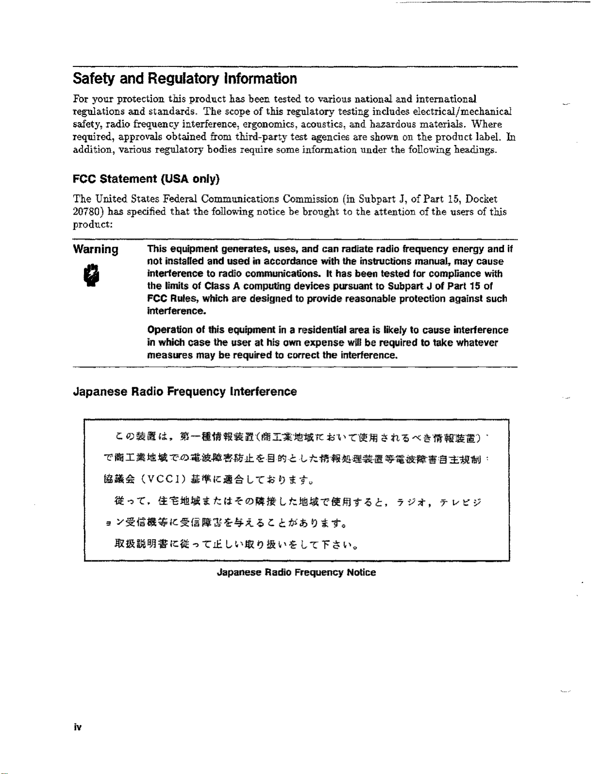
Japanese Radio Frequency Interference
i:.
0)~i1i!
C'
ffii
I~!iB~
~~~ (VCCI)
.vt..,
3 /
§tf~~~
-c.
Ii.
m-f~IH~ffl~i?1-CFmI*Jt!r~K
-Z:-.0).il[.1&:~~~J.7:L1:.
~·§-it.]-c
1iJ;ifKJljiSl-C:Jol)iTv
~"8:tt!!~
Ie:
~{§
't
t:
lIf'J;~
(;:I:
-t-
O)~ng
i-4;t ~
i:.
L
C
i;.~'
-l,
t:.:ffl~~:~~.~
t:.ttB~C'~ffl
t.J~
it>
I)
't
To
-C{fJf~
T ~
2'
n
{,«
~·ffl~·~·~) .
~:~·ilR:~~:§±:1J!J1jIJ:
C,
'7:;;t, T
i-
15
of
t:
y
~ 1&~
iv
B~• Ie:
itE ..,-cIf.
L ~\
1&
I)
1&~\i-l-cF
Japanese Radio Frequency Notice
tt
~'o
Page 5
Finland (only)
LASERTURVALLISUUS
LUOKAN 1 LASERLAITE KLASS 1 LASER APPARAT
HP 3000 Series 9x8LX/RX -tietokoneisiin voidaan asentaa Iisavarusteena muistilaitteeksi
laitteensisainen CD-ROM-levyasema,joka on laserlaite.
Kyseinen CD-ROM-levyasema on kayttajan kannalta turvallinen luokan llaserlaite.
Normaalissa kaytossa levyaseman suojakotelo estaa lasersateen paasyn laitteen ulkopuolelle.
CD-ROM-levyaseman on tyyppihyvaksynyt Suomessa laserturvallisuuden osalta
Tyoministerion tyosuojeluosasto. Laitteen turvallisuusluokka on maaritetty valtioneuvoston
paatoksen N:o 472/1985 ja standardin SFS-EN 60825 (1992) mukaisesti.
Tiedot CD-ROM-levyasemassa kaytettavan laserdiodin sateilyominaisuuksista:
Aallonpituus 790 nm
Teho 1,1 pW
Luokan 1 laser
Acoustics (Germany only)
Laermangabe (SchalldruckpegelLpA) gemessen an Arbitplatzbei norrnalen Betrieb nach DIN
45635,teil 19:
Acoustic noise (A-weight sound pressure level LpA) measured at operator's position, normal
operation, to 1807779:
HP
300 9X8LX/RX:
59dB bis (up to) 37°C, 62dB ueber (above) 37°C
v
Page 6
Safety Considerations
This product and related documentation must be reviewed for familiarization with safety
markings and instructions before operation. The following figure shows some of the safety
symbols used on the product to indicate various safety considerations.
Warning
Caution
I
The WARNING sign denotes a hazard. It calls attention to a procedure,
practice, of the like, which if not done correctly or adhered to, could result in
injury. Do not proceed beyond a WARNING sign until the indicated conditions
are fully understood and met.
The CAUTION sign denotes a hazard. It calls attention to an operating
procedure, practice, of the like, which if not done correctly or adhered to,
could damage or destroy part or all of the product. Do not proceed beyond a
CAUTION sign until the indicated conditions are fully understood and met.
Preface
This manual is intended for use by trained and experienced Hewlett-Packard field maintenance
personnel. This edition of the Installation and Configuration Guide contains technical
information about the HP 3000 Series 9X8LXjRX Family of computers listed in the table
below.
Computer Type
Description"
HP 3000 928LX
HP 3000 928RX
HP 3000 968LX
HP 3000 968RX
Other Documents Referenced in this Guide:
Part Number Title
5958-5859
5958-2370
50779-90012
2 slot Ij0chassis with a 48MHz CPU
4 slot 110 chassis with a 48MHz CPU
2 slot 110 chassis with a 64MHz CPU
4
slot 110 chassis with a 64MHz CPU
HP 3000 and HP 9000 CE HandbookA1707-90016
Computer Products Site Preparation Resources Guide
HP CEO Site Preparation Handbook
HP Predictive Support User's Guide
vi
Page 7
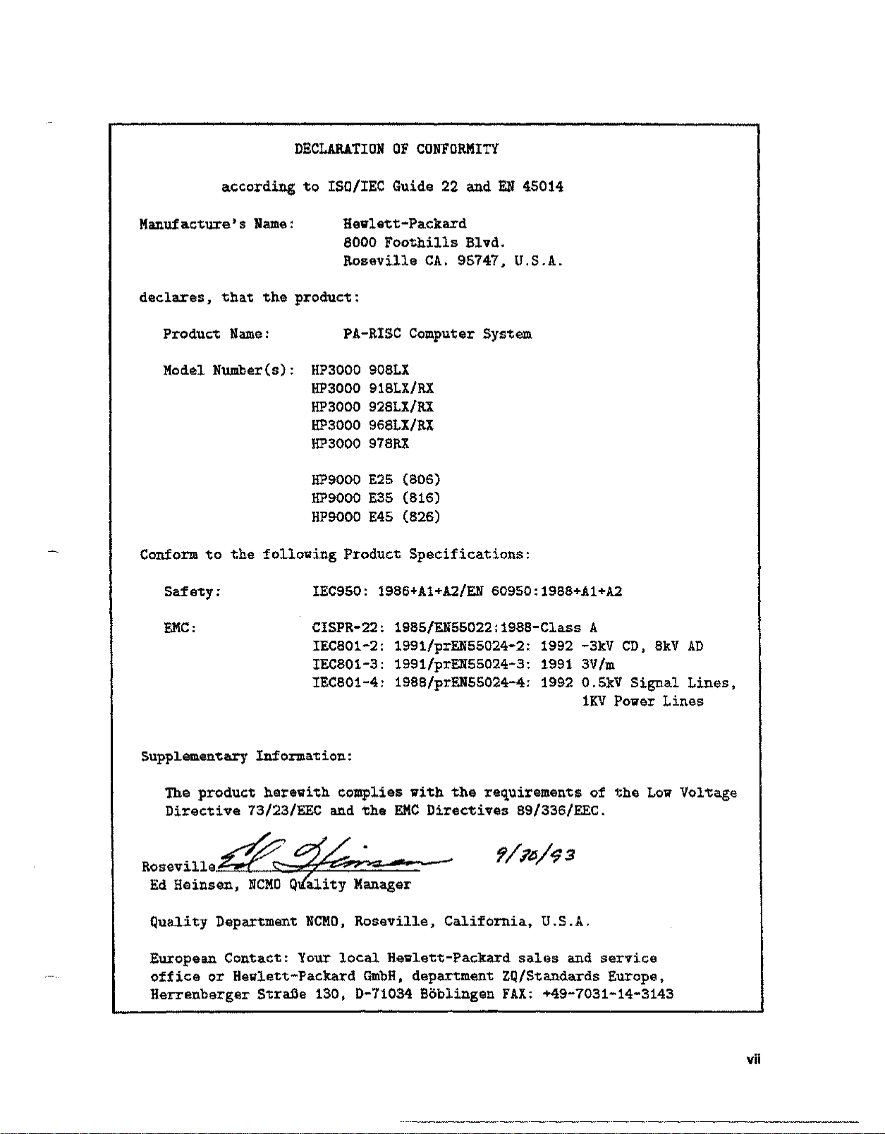
DECLARATION OF CONFORMITY
according to ISO/IEC Guide 22 and EN 45014
Manufacture's Name:
Hewlett-Packard
8000 Foothills Blvd.
Roseville CA. 95747, U.S.A.
declares, that the product:
Product Name: PA-RISC Computer System
Model Number(s): HP3000908LX
HP3000 918LX/RX
HP3000 928LX/RX
HP3000 968LX/RX
HP3000 978RX
HP9000 E25 (806)
HP9000 E35 (816)
HP9000 E45 (826)
Conform to the following Product Specifications:
Safety:
EMC:
IEC950: 1986+Al+A2/EN 60950: 1988+Al+A2
CISPR-22: 1985/EN55022:1988-Class A
IEC801-2: 1991/prEN55024-2: 1992 -3kV CD, 8kV AD
IEC801-3: 1991/prEN55024-3: 1991 3V/m
IEC801-4: 1988/prEN55024-4: 1992 0.5kV Signal Lines,
1KV Power Lines
Supplementary Information:
The product herewith complies with the requirements of the Low VOltage
Directive 73/23/EEC and the EKC Directives 89/336/EEC.
RoseVille~~
e. -~
Ed Heinsen, NCMOQality Manager
Quality Department NCMO, Roseville, California, U.s.A.
European Contact: Your local Hewlett-Packard sat.esand service
office or Hewlett-Packard GmbH, department ZQ/Standards Europe,
Herrenberger Strafie 130, D-71034 Boblingen FAX: +49-7031-14-3143
vii
Page 8

Page 9
Contents
1. About This Manual
2. Site Considerations
Site Preparation Considerations .
Physical Considerations .
Electrical Considerations. . .
Specifications . . . . . . . .
Hewlett-Packard Responsibilities
Third Party Service . .
Customer Responsibilities
Local Codes . . . . .
Data Communications Equipment .
3. Receiving The System
Unpacking and Inspection . . . . . . . . .
Unpack the HP 3000 9X8LX/RX Computer
In Case of Damage
Physical Inventory
Manuals.
Equipment .
Computer .
Claims Procedures
Repacking ....
Storage Requirements
2-1
2-1
2-2
2-2
2-5
2-5
2-7
2-7
2-7
3-1
3-1
3-4
3-4
3-4
3-4
3-4
3-4
3-5
3-5
4. Installation
Installation Procedures
SPU Installation
System Console Installation
Peripheral Equipment
DTC Installation ..
PowerTrust UPS
External Disk Cabinet
Installation Completion
4-1
4-1
4-3
4-4
4-4
4-4
4-5
4-5
Contents-1
Page 10
5. Starting the Computer System
Turning On the Computer System
Initial Power On . . . . . . .
Power On Selftest and PDC Displays
Installation Verification . . . .
Verifier global status messages
Verifier log file . . . . . . .
A. Remote Support Modem Configuration
Quick Reference .
HP Support Link (HP50759A) . . .
Hayes Smartmodem 2400 .....
Black Box V.32 Plus (Version 2.01.01)
Multitech MT224EH7
HP 37212B .
Modem Cable Pin-out . . . . . . .
Multifunction I/O PCA Modem Line Behavior
CCITT Mode AP protocol 0 . .
Bell Mode AP protocol 1 .
CCITT _BIS Mode AP protocol 2 . . .
Modem Settings (HP Predictive Support)
5-1
5-1
5-2
5-4
5-4
5-5
A-2
A-2
A-4
A-5
A-6
A-7
A-8
A-9
A-9
A-9
A-lO
A-I0
Contents-2
Page 11
Figures
3-1. Removing Loose Parts
3-2. Positioning the Shipping Box
3-3. Raising the Flap . . . . .
3-4. Removing the Computer from the Box .
Tables
2-1. Environmental Specifications . . . . . . . . . .
2-2. 2-Slot and 4-slot Chassis Power Specifications
2-3. 2-Slot and 4-Slot Chassis DC Power Specifications
2-4. Electromagnetic Susceptibility Specifications . .
2-5. 2-S1otand 4-Slot Chassis Physical Specifications
2-6. Technical Tasks/Personnel . . . . . . . . . .
4-1. A2941A Line Cord Options .
A-I. Settings for Remote Support Modem (Quick Reference)
A-2. 8-Position DIP Switch Option Settings (Set S)
A-3. 4-Position DIP Switch Option Settings (Set X)
A-4. Switch Option Settings ....
A-5. HP 37212B Switch Configuration . . . . . .
A-6. 92219QCable Pin-out . . .
A-7. Predictive Support Modems and Switch Settings
3-2
3-2
3-3
3-3
2-2
2-3
3
2-4
2-4
2-4
2-6
4-3
A-2
A-3
A-3
A-4
A-8
A-9
A-ll
Contents-3
Page 12

Page 13
About This Manual
1
This manual contains the installation instructions for the HP 3000 Series
Computer Systems.
This manual also contains information for installing the Distributed Terminal Subsystem and
for configuring modems for remote support. This manual does not include instructions for
installing networks.
This manual is organized as follows:
Chapter 1 About This Manual. Introduces the manual and describes its organization.
Chapter 2 Site Considerations. This chapter defines HP organizations and lists site
preparation responsibilities.
Chapter
instructions for unpacking the system, and putting it into position.
Chapter 4 Installation. Contains installation procedures and configuration information.
Chapter 5 Starting the Computer System. Provides instructions for turning on the
equipment, booting MPEjiX, and running the verification program.
Appendix A Support Link Modem Configuration. Provides configuration information on a
number of modems that can be used for the support link modem.
3
Receiving The System. This chapter provides information on receiving the system,
9X8jLXjRX
Family
About This Manual 1-1
Page 14

Page 15
2
Site Considerations
The HP 3000 9X8LX/RX family of computers are office environment computer systems that
do not require special environmental controls. For this reason, no specific site preparation is
required before the system is installed. Even though the computer does not require any site
preparation, there are some site considerations and responsibilities that need to be addressed.
This chapter provides the environmental and electrical specifications for the HP 3000
9X8LX/RX systems. These specifications are provided to ensure the installation site is within
the limits for the system. This chapter also lists the HP organizations and services available
for site preparation for the HP 3000 9X8LX/RX family computers. It also lists and describes
the responsibilities of the customer.
Site Preparation Considerations
The HP 3000 Series 9X8LX/RX computers are primarily designed to be used in commercial
office environments. Except for verifying the environment and AC power, very little site
preparation is required. When the computer is configured into a larger system employing
numerous peripherals and mass storage devices, you should study and become more familiar
with the contents of this chapter.
The CE or Site Preparation Specialist provides peripheral equipment power and
environmental specifications contained in the
3000 and HP 9000 CE Handbook.
It is the customers responsibility to ensure that the facility conditions are maintained in
accordance with the information and specifications contained in this chapter.
This allows Hewlett-Packard to provide support services in accordance with the
Support Services Agreement.
Physical Considerations
Since the HP 3000 9X8LX/RX is a small physical package (refer to physical specs Table 2-5 it
can be located next to a desk or placed in a dedicated computer room. Allow room for cables
and access to the front and rear of the computer cabinet.
Be sure to allow for the peripheral equipment that comes with a computer system, such as
peripheral cabinets, PowerTrust UPS, terminals, printers and other supporting equipment.
Also allow for computer materials storage.
HP CEO Site Preparation Handbook
and the
Customer
HP
Site Considerations 2-1
Page 16
Electrical Considerations
Be sure the final installation site has enough AC outlets to support the computer and the
peripherals located close to
breaker. Be very sure the AC power available meets the electrical specifications. Refer to
Table 2-2 for the exact electrical specifications.
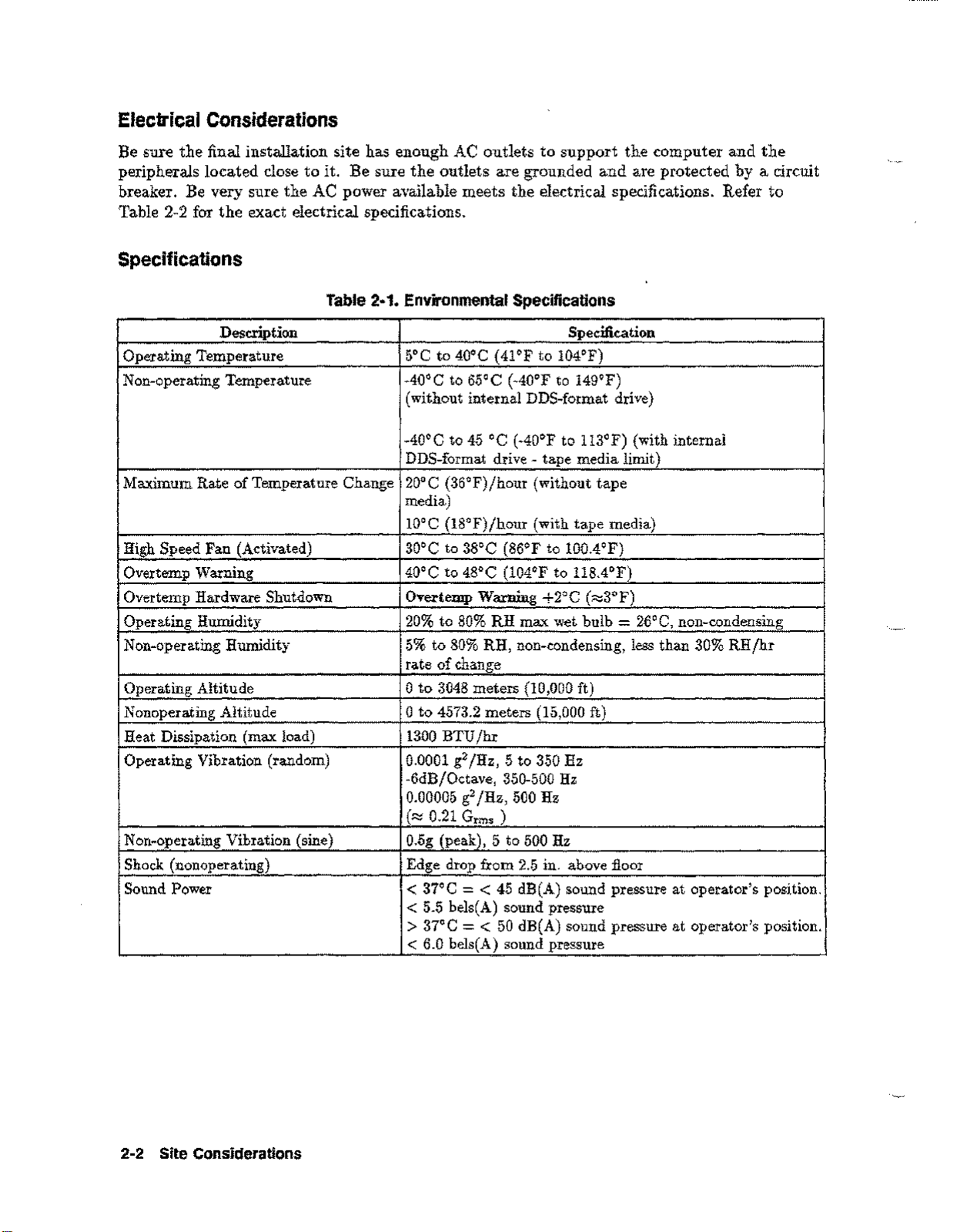
Specifications
Description Specification
Operating Temperature 5°C to 40°C (41°F to 104°F)
Non-operating Temperature -40°C to 65°C (-40°F to 149°F)
Maximum Rate of Temperature Change
High Speed Fan (Activated) 30°C to 38°C (86°F to 100.4°F)
Overtemp Warning
Overtemp Hardware Shutdown
Operating Humidity
Non-operating Humidity 5% to 80% RH, non-condensing, less than 30% RH/hr
Operating Altitude
Nonoperating Altitude
Heat Dissipation (max load)
Operating Vibration (random) 0.0001 g2/Hz, 5 to 350 Hz
Non-operating Vibration (sine)
Shock (nonoperating) Edge drop from 2.5 in. above floor
Sound Power
it.
Be sure the outlets are grounded and are protected by a circuit
Table 2·1. Environmental Specifications
(without internal DDS-format drive)
-40°C to 45°C (-40°F to 113°F) (with internal
DDS-format drive - tape media limit)
20°C (36°F)/hour (without tape
media)
lOoC (18°F)/hour (with tape media)
40°C to 48°C (104°F to 118.4°F)
Overtemp Warning +2°C (~3°F)
20% to 80% RH max wet bulb=26°C, non-condensing
rate of change
°
to 3048 meters (10,000 ft)
°
to 4573.2 meters (15,000 ft)
1300 BTU/hr
-6dB/Octave, 350-500 Hz
0.00005 g2/Hz, 500 Hz
(~ 0.21 G
0.5g (peak), 5 to 500 Hz
rms
)
< 37°C=< 45 dB(A) sound pressure at operator's position.
< 5.5 bels(A) sound pressure
> 37°C=< 50 dB(A) sound pressure at operator's position.
< 6.0 bels(A) sound pressure
2-2 Site Considerations
Page 17

Table 2-2. 2-Slot and 4-slot Chassis Power Specifications
Description
AC Input Voltage Rangel
AC Input Current-
AC Inrush Current
AC Input Power 380 watts maximum, 230 watts typical
Power Supply Output Rating 240 watts DC continuous
AC Input Line Frequency 47 to 63 Hz
Transient Tolerance:
Low Energy
High Energy
Holdup without System Reset
90 to 132 VAC and 180 to 264 VAC
6.5 A maximum load @ 100 VAC
3.5 A maximum load @ 240 VAC
2.4 A typical load @ 100 VAC&50 Hz
2.1 A typical load@120 VAC&60 Hz
1.3 A typical load @ 208 VAC&60 Hz
1.3 A typical load @ 220 VAC&50 Hz
1.2 A typical load @ 240 VAC&50 Hz
50 amperes peak, one cycle
3000 volts, lOps, 500 ns rise/fall
1000 volts, 1.2j.lsrise
20 ms @ 50 Hz (1 cycle)
Specification
Battery Backup Time
1
Note
"
The power supply is an auto-ranging power supply. It does not have to be
recon:figured to operate over its rated operating ranges. However, the system
should not be operated at voltages between the two input voltage ranges.
2
Typical load assumes 192MB memory, two internal disk drives, two
peripherals, PSI I/O card, 802.3 LAN, and a 64MHz CPU.
The power supply can provide power for up to three internal peripherals.
15 minutes with optional
600 VA PowerTrust UPS
Site Considerations 2-3
Page 18

Table 2·3. 2·Slot
and
4·510t Chassis
DC
Power Specifications 3
Note
"
Nominal
Voltage Current
+5V4
+5V_S OA
+12V
-12V OA
3
Total power must not exceed 240 watts.
4
+5V current includes +5V_S current.
Radiated 3V
Conducted
Radiated Magnetic Field Immunity
Electrostatic Air Discharge
Electrostatic Contact Discharge
Minimum
3A 27A
OA 6.67A
Table 2·4. Electromagnetic Susceptibility Specifications
Maximum
Current Voltage Voltage
5A +5.10V
2A
Minimum
+5.10V +5.25V
+lL69V +12.36V
-11.69V
3V rrns, 30 Hz to 100 MHz
1V rrns, 100 MHz to 400 MHz
1 gauss p-p, 48 Hz to 198 kHz
5 kV - no effect
25 kV - no hardware failure
4 kV
Maximum
+5.25V
-12.60V 100 mV
jm,
28 MHz to 1 GHz
p-p Ripple
50 mV
100mV
100 mV
Table 2·5. 2·Slot and 4·Slot Chassis Physical Specifications
Description
Width 222 mm (8.74 in.)
Height
Depth
Weight
Specification
430 mm (16.93 in.)
533 mm (20.98 in.)
31.8 kg (70 lbs)
2·4 Site Considerations
Page 19

Hewlett-Packard Responsibilities
Each member of the Hewlett-Packard service organization is dedicated to making sure that
each customer realizes the maximum benefit from their computer system. HP is responsible
for the installation and initial verification of the computer system. Table 2-6 summarizes a
number of site preparation technical tasks and lists the personnel who should be responsible
for completing each task.
Third Party Service
If an HP 3000 Series 9X8LX/RX Computer system and/or applications software is purchased
from a "third party vendor", that third party is responsible for providing consultation services
on the system operation and applications software.
In the situation of a third party purchase, a maintenance agreement for hardware and Account
Management Service CAMS)for software are available directly from Hewlett-Packard.
Site Considerations 2-5
Page 20

Table 2·6. Technical TasksjPersonnel
Technical Task
Line voltage measured
Electrician and HP CE
Power line frequency measured HP CE
Power line noise levels measured HP CE
Neutral to ground levels measured HP CE
Safety and ground connections verified
Advice on correct circuit breakers and wire sizes
Electrician and HP CE
Electrician and HP CE
Verification that maintenance power outlets (those used for Electrician
floor cleaning, etc.) are on separate circuits from the
computer system.
Person Responsible
Recommendations about lightning protection
HP CE
Measurements and recommendations on radiated interference HP CE
Answers to questions concerning modems and modem
HP CE
options
Thermal load of HP equipment
Thermal load of non-HP equipment
Total air conditioning required
HP CE
Customer/Vendor
Customer/Contractor
2-6 Site Considerations
Page 21

Customer Responsibilities
The customer is responsible for scheduling, planning, and preparing a suitable environment
for the complete computer system. The Hewlett-Packard CE will be available to assist the
customer throughout the planning and preparation for and the installation of the system.
In the
Warranty Information (Section 1) and the On-Site Customer Documents (Section 2). Pay
particular attention to the contents of the Customer Responsibilities page in Section 1 and the
forms contained in Section 2. (The forms in Section 2 will be completed as the site planning
preparation and equipment installation progresses.)
Computer Products Site Preparation Resource Guide,
read the Site Planning and
Local Codes
Special local codes exist in some locations regulating the installation of computer equipment.
The customer is responsible for making sure the system is in compliance with all local laws,
regulations, and codes for mechanical, building, and electrical distribution systems prior to
system installation.
Data Communications Equipment
The customer is responsible for ordering and installing all required data communications
equipment such as:
• Modems (Consult with CE for Hewlett-Packard requirements.)
• Telephone equipment
• Equipment supplied by companies other than Hewlett-Packard
• Any hardware or cables for connection or installation
Site Considerations 2-7
Page 22

Page 23

3
Receiving The System
This chapter contains information for unpacking and inspecting the computer, taking
inventory of shipped goods, filing claims, repacking, and storing the system.
Unpacking and Inspection
The computer and-its accessories may be shipped in more than one container. First, check to
ensure that all the containers ordered by the customer are present, as specified in the carrier's
Bill of Lading. Inspect each container for evidence of mishandling during transit. If any of
the containers are damaged, request that the carrier's agent be present when the container is
opened.
Unpack the shipping containers and inspect each item for damage. Look for damage such as
broken controls and connectors, dented corners, scratches, bent panels, and loose components.
Check the rigid foam packing material for signs of damage, which could indicate rough
handling during transit.
Unpack the HP 3000 9X8LX/RX Computer
The unpacking of the computer is shown on the flap of the shipping box. To remove the
computer from the shipping box, perform the following steps:
Warning
DO NOT try to lift the computer out of the shipping box. The shipped weight of
the computer exceeds 70 pounds (32 kg). If the computer is dropped it could
cause injury and will cause damage to the internal components of the computer.
Receiving The System 3-1
Page 24

1. Remove all loose parts inside the shipping box, and the inside shock absorbing packing
materials. See Figure 3-1.
Figure 3-1. Removing Loose Parts
2. Close the flap with the handles cut in
3. Position yourself so that you must reach across the box to grasp the handles. See
Figure 3-2.
Figure 3-2. Positioning the Shipping Box
it,
the other three flaps should be open.
3-2 Receiving The System
Page 25

4. Grasp the handles and carefully pull the shipping box toward yourself until the shipping
box rests on its side, with the handles on top. This positions the computer in an upright
position, resting on its feet. See Figure 3-2.
Note
5. Open the top
the left and right side.
The feet on the bottom of the computer slide easily on cardboard. They
should also slide easily over hard floors or carpets.
flap.
See Figure 3-3. Reach into the shipping box and grasp the computer on
Figure 3-3. Raising the Flap
6. Pulling alternately with your left and right hand, slowly slide the computer out of the
shipping box. See Figure 3-4. Save the shipping box and packing materials in case the
computer needs to be moved to another location.
Figure 3-4. Removing the Computer from the Box
Receiving The System 3-3
Page 26

In Case of Damage
If damage
is
observed, refer to the claims Procedures section later in this chapter.
Physical Inventory
When the shipping containers is opened, locate the picklist which contains a list of equipment
supplied. Compare the product and option numbers on the picklist with the purchase order to
verify that the shipment is correct.
Manuals
Ensure that all of the manuals listed have been received. If any of the manuals are damaged
or missing, refer to the Claims Procedure section.
Equipment
Ensure that all of the equipment on the list has been received. If any of the equipment is
damaged or missing, refer to the Claims Procedures section.
Computer
Ensure that the model and serial numbers are identical to those specified on the picklist. The
model and serial numbers are printed on a general information label, located on the back of
the computer.
The computer comes with some peripherals embedded in the SPU cabinet. Check that these
peripherals are integrated and that they match the equipment list. The general information
label contains the serial numbers of the embedded peripherals, along with regulatory approvals
and electrical ratings.
Claims Procedures
Notify the nearest Hewlett-Packard Sales and Service Office if the shipment is incomplete,
damaged, or fails to meet specifications. If damage occurred in transit, notify the carrier as
well.
Hewlett-Packard will arrange for replacement or repair without waiting for settlement of
claims against the carrier. In the event of damage in transit, retain the packing container and
packing materials for inspection.
3-4 Receiving The System
Page 27

Repacking
When computers must be reshipped, use the original shipping and packing materials,
if available. Contact the local Hewlett-Packard Sales and ServiceOfficefor repacking
information and materials.
Storage Requirements
Hewlett-Packard computer equipment can be stored or shipped in environments that fall
within the followinglimits:
• Storage Temperature (with tape media): -400to 450C (-400to 1130F)
• Storage Temperature (without tape media): -400to 650C (-400to 149.0F)
• Rate of change (with tape media): <100Cjhr.
• Rate of change (without tape media): <200Cjhr.
• Non-operating humidity; 5% to 80% non-condensing
• Humidity rate of change: <30% RHjhr.
Caution
•
The computer and components should be protected from environmental
extremes that can cause condensation within the equipment. When installing
the equipment, allow time for the temperature of the equipment to stabilize to
the site environment.
Receiving The System 3·5
Page 28

Page 29

Installation
4
This chapter contains information for installing the
Computer systems. All installation tasks should be performed by trained and experienced
personnel only. The installation tasks are as follows:
• System Processor Unit (SPU) Installation
• System Console Installation
• Peripheral or Optional Equipment consisting of:
Datacommunication Terminal Controller (DTC) Installation
PowerTrust UPS Installation
External Disk Cabinet Installation
Warning
Be sure the SPU is not plugged into a wall outlet or PowerTrust UPS before
starting the Installation Procedures.
HP
3000 Series 9X8LX/RX Family
Installation Procedures
Tools required: Standard CE hand tool set, plus a #10 Torx driver.
SPU Installation
To install the SPU, perform the following steps:
1. Observe all ESD precautions while performing installation procedures on any electronic
equipment.
2. Remove the I/O RFI covers from the slots that will hold any I/O cards to be installed.
Note
Refer to the
I/O card slot loading and configuration information .
CE Handbook
(part number A2051-90003) for specific details on
•
3. Install optional I/O cards into an appropriate I/O slot. Make a note of the type of card
inserted into the I/O slot, as well as the slot number. This information will be used during
system configuration.
4. Connect all external peripherals to the appropriate I/O connector at the back of the SPU.
Installation 4-1
Page 30

a. The top connector on the multifunction I/O card is for SCSI peripherals. If there are
no additional SCSI peripherals to connect, install a SCSI terminator (part number
1252-3932)to the SCSI connector.
b. Refer to the documentation that came with the peripheral device for specificinstallation
instructions for that device.
c. Use only the cables that comewith the peripheral device.
Note
d. Make a note of all device addresses that apply to system configuration, along with the
slot number that they are connected to. Refer to the note in step 1.
e. Connect a BNC T connector to the ThinLAN connector on the Multifunction I/O card.
Note
f. Do not leave any open I/O slots after all I/O cards are installed. This would violate the
RFI specifications accommodated by the I/O slot covers.
5. Plug one end of the line cord into the AC receptacle at the rear of the SPU.
Note
•
SCSI cable part numbers are listed in
Chapter4of the
information.
The ThinLAN connector is enabled at the factory, and the AUI LAN
connector is disabled. If the AUI LAN connector needs to be enabled, the
Multifunction I/O card has to be removed and jumper block WI needs to be
repositioned. Refer to the
information.
Be sure the appropriate localized line cord (refer to Table 4-1 for line cord
selection) is available with the SPU.
Also, if the computer comes with a PowerTrust UPS, the UPS has to be
installed before the SPU is powered up. The lime cord that comes with the
SPU is used as the AC line cord for the UPS, and the SPU connects to the
UPS with one of the conveniencecords that come with the UPS.
CE Handbook
CE Handbook, Chapter4for more configuration
has external SCSI cabling and configuration
Chapter
8 of the
CE Handbook.
4-2 Installation
Page 31

Table 4·1. A2941A Line Cord Options
Part Number
Country
8120-1351 United Kingdom
8120-1369 Australia
Male Type
BS1363
AS3112
8120-1689 Europe CEE7jVII
8120-1751 US 120V
8120-3996 US 240V
8120-2104
8120-2956
Swiss SEV type 12
Denmark
8120-4211 South Africa
8120-4753
Japan
5-15P
6-15P
DHCR
SABS
JIS C 8303
System Console Installation
The recommended system console terminal for the HP 3000 9X8LXjRX family of computers
is the HP 700/96 terminal. If the customer uses any other type of terminal for the system
console, refer to the documentation that comes with the equipment for any installation
information.
HP 700/96 System Console
1. Connect the system console cable (part number A1703-63003) to the Multifunction I/O
card connector labeled Console, on the rear of the SPU.
2. Connect the other end of the system console cable to the console connector labeled
DATACOMM., located on the back of the console. Refer to the documentation that came
with the console for specific installation instructions that apply to the device being used as
the system console.
3. The HP 700/96 terminal default settings match the system requirements for terminal
configuration.
Installation 4·3
Page 32

Peripheral Equipment
Be sure to refer to the documentation that comes with any peripheral equipment for specific
installation instructions.
DTC Installation
There may be multiple DTCs to be installed on the system. Repeat the installation
instructions for each DTC installed on the system.
1. The DTCisconnected to the SPU through the LAN link.
2. Connect another BNC T connector (part number 92227N)to the connectorlabeled
Interface
3. Connect the LAN cable (all ready connected to the SPU) to the DTC BNC T connector.
4. If there is another DTC, connect a LAN cable from the other end of the BNC T connector
to the next DTC.
5. On the last DTC installed, connect a LAN terminator (part number 92227P) to the
remaining side of the BNC T connector assembly.
6. Cover all the BNC T connector assemblieswith the fabric anti-static coverthat came with
the T connector.
7. Refer to the documentation that came with the DTC for complete installation and
configuration instructions.
Note
PowerTrust UPS
To connect the PowerTrust UPS to the SPU, perform the followingsteps:
on the back of the DTC.
Be sure that each end of the system LAN link has a BNC LAN Terminator
(part number 92227P) installed.
LAN
1. Locate the PowerTrust System Guide (part number 5961-8383).
2. Take the time to thoroughly read and understand all the necessary procedures outlined in
the PowerTrust Guide. The PowerTrust requires recharge time beforeit is considered ready
for normal operation.
Note
The line cord for the computer is used as the line cord for the UPS. The
computerisconnected to the UPS with a conveniencecord supplied with the
UPS. Be sure the appropriate localized line cord is used with the UPS (refer
to Table 4-1).
"
4-4 Installation
Page 33

External Disk Cabinet
To connect the external disk cabinet to the SPU, perform the following steps:
1. Be sure the disk cabinet ON/OFF switch is in the OFF (0) position.
2. Plug the power cord into the back of the disk cabinet, just below the ON/OFF switch.
3. Connect the end of the SCSI cable (part number 5062-3383 or
connector on the back of the disk cabinet.
4. Connect the other end of the SCSI cable to the top connector labeled SCSI on the
computer back panel. Be sure the connector is securely fastened to the computer back
panel.
5. Connect the external disk SCSI terminator (part number 1252-3920 or
connector on the back of the disk cabinet.
6. Plug the disk cabinet power cord into an appropriate ac wall outlet.
7. This completes the hardware installation of the external disk cabinet. Refer to the
documentation that comes with the disk cabinet for any additional information.
K2296)
to the bottom SCSI
K2291)
to the top
Installation Completion
1. Make sure all (SPU and peripheral devices) power switches are in the OFF position.
2. Connect the SPU power cord to an appropriate AC outlet, or PowerTrust UPS outlet.
3. Connect all peripheral device power cords to appropriate AC outlets.
The computer system should now be ready for initial power up selftest, and system
configuration. Continue to
Starting the Computer System
Chapter 5.
Installation 4-5
Page 34

Page 35

5
Starting the Computer System
The procedures listed in this chapter show you how to interact with the computer to get you
to the ISL (Initial Software Load) prompt
command to load the MPEjiX operating system software can be issued.
Turning On the Computer System
The computer and its external equipment contain built in selftest programs. These programs
automatically run each time the computer and the equipment are turned off and then turned
on again.
Remember, depending on how much internal memory the computer has, the computer selftest
can take up to approximately 2 to 5 minutes to complete.
(IS1>_).
When the ISL prompt is displayed, the
Caution
Do not
equipment while power is on can cause disk damage and loss of data .
move the computer or disk cabinet while the power is on. Moving the
•
Initial Power On
When turning on the computer system (this includes all equipment) be sure to follow the
sequence listed below:
Caution
If any of the external equipment has been OFF due to any environmental
problem, such as heating or air conditioning failure, allow approximately 30
minutes for the temperature of the equipment to stabilize before turning on
the computer.
•
1. Turn on all the external equipment (except the DTC) connected to the computer first. The
DTC will be turned on later.
2. Check all READY or ONLINE indicator lights on the external equipment to be sure that
they indicate being powered up and ready.
3. When all external equipment indicate READY or ONLINE by their particular indicator
lights, press the computer ON
jOFF
switch to the ON position.
Startingthe Computer System 5·1
Page 36

Power On Selftest and
The primary display for the computer is the system console in conjunction with the status
display lightson the front of the computer.
1. The firstthing displayed on the computer console isa lineof messages along the bottom of
the console screen indicating the selftestprograms are running:
PDe
Displays
TEST nnnn REMOTE: disabled inactive multiple ACCESS FAULT:
l
While this display is activethe amber Attention light should be on. This indicates that a
testis being performed.
2. When selftestiscomplete, the console displays a screen similarto the following:
xx ME of memory configured and tested.
Primary boot path:
Alternate boot path:
Main Menu ------------------------------------------------------------
Command Description
BOot [PRIIALTI<path>]
PAth [PRIIALT] [<path>]
SEArch [DIsplayIIPL] [<path>]
56/52.6
56/52.0
(dec)
(dec)
Boot from specified path
Display or modify a path
Search for boot devices
yy
J
COnfiguration menu
INformation menu
SERvice menu
DIsplay
HElp [<menu> I<command>]
RESET
Main Menu: Enter command or menu>
5-2 Startingthe Computer System
Displays or sets boot values
Displays hard~are information
Displays service commands
Redisplay the current menu
Display help for menu or command
Restart the system
Page 37

The xx
commands or menu can be entered with the letters in capitals, for example; booting from
the primary boot path would be:
MB
indicates the amount of memory in the system. Within the main menu, the
Main Menu: Enter command or menu>BOPR1
or a menu request would be:
Main Menu: Enter command or menu>1N
Where the
3.
At the Main Menu: Enter commandor menu> prompt, enter the boot from primary boot
path command
4. The system returns a query of:
Type Y
enabled, you must interact with the Initial Program Loader (1PL) software. An Nentry will
still put you into 1PL.
5. At this point the Initial System Loader (ISL) prompt (ISL» is displayed. The system
should be waiting for your response to the 1SL>prompt.
6. Respond to the 1SL> prompt with the STARTcommand, (or any of the applications
available in 18L). The STARTcommand launches the
IN
entry would display the system hardware information.
(BO
PRI).
Interact with 1PL Y/N?>
(Enter).
The HP
ISL> START
3000
[Enter)
9X8LX/RX systems do not have the autoboot function
[Enter)
(Enter)
MPEjiX
operating system software.
7. After a few minutes, you are prompted to confirm the date and time as shown below.
you do not respond within
15
seconds, the system accepts the displayed date and time
default, and continues with the start-up process.
a. If the date and time displayed are accurate, type Y and press
time out.
b. If they are not, type!! and press
Enter the correct date and time when prompted. Time must be entered in 24-hour
format (for example,
specified.
MPE/iX launch facility
Initialize_genesis - Version «870204.1552»
TUE, AUG11, 1993, 10:20:03 AMCy/n)?
[TMDX_DAMJn n n n
Initialize genesis completed.
The fundamental operating software is starting.
5:00
pm, is entered as 17:00). Seconds default to 00 if not
(RetUffi)
within the 15 seconds allowed.
!
(Return),
or wait for the
If
by
Starting the Computer System 5-3
Page 38

During the launch of the MPW fiX operating system
ERROR
and
WARNING
messages will be
displayed on the console telling you that un configured devices are attached to the system.
These messages are normal during the first boot up. They appear during the first boot up
because the final configuration is not done. Among the messages you may see are these:
Dee;laming 103-5, Addldev to class failure (HLIOstatus FF6AOOBD,.
Dec;laming 103-5, Addldev to class failure (HLIOstatus FF6AOOBD,.
DCe STARTUP - ERROR
The system is making many internal checks and is reporting that the configuration is not
complete. When this checking process is complete a welcome message is displayed on the
console. You are automatically logged on to the system as
OPERATOR.SYS.
8. When the system prompt (:) is displayed, all the system selftests are complete. At this
time, turn on the DTC( s). The configuration process can begin.
Installation Verification
Once the configuration is complete, the system installation can be verified by the use of the
Verifier
The Verifier program usually resides in the
command file named
program.
VERIFY. PUB. SYS
DIAG
group of the
SYS
account. However, a
is provided to setup the proper environment for Verifier
operation.
To invoke MPEfiX Verifier log on as Manager.Sys (or any log on with SM, OP or DI
capability) and enter the following:
VERIFY
Follow the program prompts on the console screen. Verifier performs more than one task at
one time. For this reason, you will frequently see messages for assorted devices interspersed
with one another, this is normal.
Verifier global status messages
When Verify is finished it prints one of three status messages indicating:
If everything verified as
System verification is complete. Everything is okay.
Proceed ;lith the next operation ...
okay
a
.iessage
similar to the following appears:
If something needs
attention,
a message similar to the following appears:
5-4 Starting the Computer System
Page 39

ATTENTION: System verification indicates that noncritical
devices are not all working.
This message indicates a problem with a
except:
If there is an
system disks, nonsystem (private volume) disks and tape drive logical device 7.
error,
a message similar to the following appears:
noncritical
device. A noncritical device is everything
ERROR: System verification failed. Critical devices are
not functional. Do not continue to use the system.
This message indicates a
the problem has been corrected.
volume) disks and tap e drive logical device 7.
critical
device failed. You should not attempt to use the system until
Critical
devices are all system disks, all non-system (private
Verifier log file
In addition to the messages described above, MPE/iX Verifier creates a log file named
This file contains a detailed history of the verification actions and status messages and a
system I/O map which shows the current status of each device and the overall system status.
VERLOG
equation can be used to redirect it to another location.
is created in the group and account from which Verifier is invoked. However, a file
VERLOG.
Starting the Computer System 5-5
Page 40

Page 41

A
Remote Support Modem Configuration
This section contains information for connecting specificmodems to the RP 30009XSLX/RX
Family Computer System. This section also discussesthe signal line behavior of the
Multifunction I/O modem interface to aid in configuringmodems that are not listed.
General rules for configuringmodems:
• The modem must be set up to respond to DTR.
• CTS should follow RTS.
• DSR must follow OR, not DCD.
• For Bell mode, the modem should disregard RTS.
• Set both local and remote modems to either:
o the same compression mode, OR
o to NO data compression.
If problems occur connecting two modems, usually the fault is that one is enabled for
some MNP level and the other modem is set for no data compression.
If the modem sends up-modem dialog with all of the signals asserted, it is possible for the user
to be logged offimmediately when a password is enabled for the Access Port. This can be
corrected by setting the modem so it does not report connection status via the data path.
Note
V.22bis/V.25bis modes are not supported on the A1703-60003or A1703-60022
Multifunction I/O interfaces.
Remote Support Modem Configuration A-1
Page 42

Quick Reference
Table A-I is a quick reference table for the supported modems for remote support. For
detailed information, refer to the appropriate section of this appendix.
Table A·1. Settings for Remote Support Modem (Quick Reference)
Modem Model Settings
HP50759A (Support Link)
Hayes Smartrnodem 2400 S3, S9, and S10: Down
Black Box V.32 Plus (2.01.01)
Multitech MT224EH7 Xl, X4, S3, S7, and S8: Down
HP 37212B
HP Support Link (HP50759A)
Supported modes:
• Bell
• CCITT_OM
• CCITT_AM
• CCITT_BIS_OM
• CCITT _BIS_AM
xi,
X2, X3, X4, and S8: Down
si,
S3, S4, S5, and S6: Up
S2 and S7: Do not care
si,
S4, S5, S6, and S7: Up
S2: Do not care
AT&D2&Sl&Cl&R
(See Black Box V.32 section for details)
X2, X3,
si,
S3, S8, S9, SI1, and S12: Up (1)
si,
S2, S4, S5, and S6: Up
S2, S4, S5, S6, S7, and S10: Down (0)
Supported cables:
• HP 922I9Q - Bell, CCITT_OM, CCITT_AM
• A1703-63006 - CCITT_BIS_OM, CCITT _BIS_AM
A-2 Remote Support Modem Configuration
Page 43

Auto-dial modes: Hayes
This modem is the standard HP Support Link. It supports V.22bis line discipline, but does
not support V.25bis auto-dialing. In order for V.22bis answer mode to work properly, DSR
must follow OH. Data Compression should be set
cause problems when connecting to other modems that do not have data compression.
Table A·2. 8·Position DIP Switch Option Settings (Set S)
OFF.
Setting data compression
ON
can
Note
Switch
Sl up DTR Normal
S2
S3
S4
S5
S6
S7
S8
xx means do not care.
Switch
Xl
X2
X3
X4
Position
xx
up Suppress Responses &QO
up Enable Echo of commands
up
up DCDjDSR Normal
xx
down Enable Command Mode
Table A·3. 4·Position DIP Switch Option Settings (Set X)
Position Description
down
down DSR Follows OR
down Use RP Defaults
down No ENQjACK Pacing
CTS Normal
Description
Verbose Responses
Enable Auto-Answer
Depends on phone line
&RO
&Sl
&EO &E3 &E6 &ElO &E14 $BA1
&E8
Option Command
&D2
VI
E1
SO=l
&C1 &Sl
Option Command
Note
•
An
AT1517
BO El Ml QO Vl XO &EO &E3 &E6 &E8 &El0 &E14 &QO
$MB2400 $SB2400 $BAl &Wl
&AO $AO
&Vl &Wl
command should have the following output:
&BO &BSl &Cl &D2 $DO $F1 &GO &10 &MO $MIO &RO $RO &S1 &T5
OK
Remote Support Modem Configuration A-3
Page 44

Hayes Smartmodem 2400
Supported modes:
• Bell
• CCITT_OM
• CCITT_AM
Supported cables:
• Must use 92219Qmodem cable.
Auto-dial modes: Hayes.
This modem drives circuit 111 (Pin 23) instead of using it as an input. With either cable
(92219Q or AI703-63006), the Multifunction I/O PCA and the modem, drive the same line.
Caution
I
Turn offall data compression modes.
The Hayes defaults for the modem lines must be changed to the following:
This modem should not be used because all HP cables connect circuit 111 to
the modem. If this modem is connected, both the Multifunction I/O PCA and
the modem drive circuit 111. This modem has been used in the past with the
CIa based AP card and had the same problem.
Table A-4. Switch Option Settings
Switch
SI
S2 xx
S3
S4 up Characters echoed
S5
S6
S7
S9
S10
Position Description Option
up DTR normal
down
up Auto-Answer enabled
up
up RJ-ll
down
down
Result codes disabled
Detect Carrier
CCITT
Return to command state
AT&D3&W
ATQl&W
ATEl&W
ATSO=I&W
AT&Cl&SI&W
AT&JO&W
ATBO&W
AT&D3&W
Command
Note
xx means do not care.
tI
A-4 Remote Support Modem Configuration
Page 45

Black Box V.32 Plus (Version 2.01.01)
Supported modes:
• Bell
• CCITT_OM
• CCITT_AM
Supported cables:
• Must use 92219Q modem cable.
Auto-dial modes: Hayes.
This modem does not work with v.22bis because it does not supply 112 and because the sense
of 111 is backwards (TRUE means low speed, FALSE means high speed). The fact that 111
is backwards is not too big a problem because the modem can be configured to ignore Ill.
Change so that DTE Fallback is
means that the Multifunction I/O PCA always thinks it is running at the lower speed. If you
set the speed for twice the desired speed, then it will work at the desired speed. It is best not
to use this modem with any of the CCITT bis protocols.
The Black Box defaults for all of the modem lines are incorrect and must be changed before
this modem will work properly. To do this from the front panel, go into the Change DTE
Parameters and set the
Responds to DTR
DSR is Normal
DCD is Normal
CTS follows RTS
following:
Disabled.
This is the factory default. Not supplying 112
This can be done with the following AT command:
For Hayes dialing, make certain that the AT command set is enabled. It is normally good to
disable status messages to the host by using the
The current configuration can become the power-on configuration by using the
command.
This modem does not do any rate shifting. So the DTE rate and the DCE rate must be the
same.
This modem seems to work in AP mode with the protocol set to either Bell or CCITT. It does
not work with the modem protocol set to CCITT _BIS. Make certain to configure the modem
to ignore 111, or configure the Access Port to set FS low. It also seems to work fine in normal
mode (i.e. under host control).
AT&D2&S1&C1&R
ATQ1
command.
AT&W
Remote Support Modem Configuration A·5
Page 46

Multitech MT224EH7
Supported modes:
• Bell
• CCITT_OM
• CCITT_AM
• CCITT_BIS_OM
• CCITT _BIS_AM
Supported cables:
• HP 92219Q - Bell, CCITT_OM, CCITT_AM
• A1703-64006- CCITT_BIS_OM, CCITT_BIS_AM
Auto-dial modes: Hayes, V.25bis.
Note
"
The configuration of the hardware switches on the modem are:
8-position DIP-Switch (S switches):
Switch:
4-position DIP-Switch (X switches):
Switch: 1 2 3 4
For Hayes mode to work correctly,
connection goes down. For Hayes,
must be set.
The version of the modem has a problem when dialing with V.25bis where if
the number that is dialed is busy, DSR does not drop. This same problem
causes V.25bis error indications to be improperly decoded, meaning that the
modem time-out timer must expire before we know that the attempt failed.
This also means that multiple dialing attempt will always fail. If the DSR
jumper is set so that DSR followsDCD, this problem goes away.
1
2
3
4
5
6
UP UP DOWN UP UP UP DOWN DOWN
DOWN UP UP DOWN
AT&RO
AT$VO
must be set so that it drops CTS when the
must be set. For V.25bis dialing,
7
8
VT$Vl
and
AT$BAl
Hayes dialing parameters:
BO El Ml QO RO Vl XO &El &E4 &E6 &E8 &El0 &E13 &E15
$MB2400 $SB2400 $BAl &WO
SO S2 S3 S4 S5 S6 S7 S8 S9 S10 Sll S12 S24 S25 S30
001 043 013 010 008 002 030 002 006 007 070 050 020 000 000
$AO &AO &BO &BSl &Cl $DO &D2 #DBO $EBO $F1 &GO #LO $MIO &MO
&PO #P2 &QO &Q3 $RO &R1 &Sl $T1 &T4 $VO $VDO &XO YO
$MB2400 $SB2400 $BA1 &WO
OK
A-6 Remote Support Modem Configuration
Page 47

For V.22bis auto-answer, internal jumper DSR must be set so that DSR follows OH. The
factory default is for DSR to follow CD. This is different from the Support Link where the
factory default was for DSR to follow OH. There does not seem to be an AT command that
does this.
V.25bis dialing parameters:
BO E1 M1 QO RO V1 XO &E1 &E4 &E6 &E8 &E10 &E13 &E15
$MB2400 $SB2400 $BA1 &WO
SO S2 S3 S4 S5 S6 S7 S8 S9 S10 S11 S12 S24 S25 S30
001 043 013 010 008 002 030 002 006 007 070 050 020 000 000
$AO &AO&BO&BSl &Cl $DO &D2 #DBO $EBO $Fl &GO#LO $MIO &MO
&PO #P2 &QO&Q3 $RO &Rl &Sl $Tl &T4 $Vl $VDO &XOYO
$MB2400 $SB2400 $BAl &WO
VAL
To modify a MT224E7B:
• Open modem and change the DSR jumper.
• Set switches on the bottom of the box to above.
• Send AT&RO
• For Hayes dialing, send AT$VO.
• For V.25bis dialing, send AT$V1.
HP 372128
Supported modes:
• Bell
• CCITT_OM
• CCITT_AM
• CCITT_BIS_OM
• CCITT_BIS_AM
Supported cables:
• HP 92219Q - Bell, CCITT_OM, CCITT_AM
• A1703-64006 - CCITT_BIS_OM, CCITT_BIS_AM
Auto-dial modes: None
It is best to use this modem in CCITT mode because it causes the Access Port to hang up if
used in Bell mode at 1200 baud. It can be used in Bell mode at 2400 baud, or either 1200 or
2400 in CCITT mode. This modem can not be dialed with either Hayes or V.25BIS auto-dial
protocols. Table A-5 describes the switch settings.
Remote Support Modem Configuration A-7
Page 48

Table A·5. HP 372128 Switch Configuration
Note
Switch
SI down
S2
S3
S4
S5
S6
S7
S8
S9
SID
S11
S12
Although this modem claims to be able to dial using V.25bis, it only uses the
V.25bis line discipline. The command set does not match the set specified in
the V.25bis specification.
Position
down
up
down Primary channel
down
down
down
up
up
down
up
up
Computer mode operation (HP command set)
1 start, 8 data and 1 stop
Error correction disabled
No Flow control
DSR/CTS/CD to RS-232-C definition
DTR behaves to RS-232-C definition
Description
Modem Cable Pin-out
Table A-6 list the pin-outs for the 92219Q cable, which is most often used to connect the
Access Port to the support modem.
A·a
Remote Support Modem Configuration
Page 49

Table A-S. 92219Q Cable Pin-out
Computer
End
2
3
8 RTS
22
20
6
9
4
and
23 FS
7
The pin-out for the A1703-63006 cable is the same except that pin 9 on the computer end
is routed to pin 12 on the modem end and that Line functions as Rate Select (RS). This
cable is only used with the A1703-60003 SCSI/Console/LAN Multifunction I/O interface for
V.22bis /V .25bis applications.
Signal
Name End
TD
RD
CTS
DSR
DTR
RI
5
DCD
GROUND 7
Modem
3
2
4
5
6
20
22
8
23
Multifunction I/O peA Modem Line Behavior
CCITT Mode AP protocol 0
This protocol is known as HP-UX CCITT. The card waits for RI before raising DTR. It
also raises RTS when it raises DTR. If DSR does not come up within 25 seconds, DTR goes
back down. The connection also depends on CTS and DCD. DCD can drop for up to 400ms
before the connection will drop. CTS must stay high always. Once CTS drops, the connection
starts to drop. A new connection cannot occur until DSR, DCD and CTS all drop. FS can be
programmed to either state via the
Bell Mode AP protocol 1
This is sometimes called Bell simple protocol. It raises DTR when it can accept a connection.
The connection is valid when it sees DCD. It drives RTS whatever it was when Remote is
enabled (usually, RTS is low) and does not look at DSR or CTS. When a disconnect is done,
DCD must drop before a new connection can be made (i.e. it will not raise DTR until DCD
drops).
CA
command.
Remote Support Modem Configuration A-9
Page 50

CCITT _BIS Mode AP protocol 2
This protocol is CCITT V.22bis. It requires the special cable A1703-63006 which is just like
the 92219Q cable with the exception that pin 9 on the computer end is routed to pin 12 (RS)
rather than pin 22 CRI). DTR
connection is established when DSR is high. CTS can drop for an indefinite amount of time
without dropping the connection. The card will not send data to the modem when CTS is
low. DCD can drop for up to 400ms before the connection is dropped. Once the connection
is dropped, DSR, DCD and CTS must all go low before a new connection can be made. RS
controls what speed the card sends to the modem. If RS is high, the programmed baud rate is
used. If RS is low, half of the programmed baud rate is used. If you use the 92219Q cable, the
baud rate will most certainly be half the programmed baud rate, since
be down. FS can be programmed to either state via the
is
raised whenever a connection is allowed. RTS follows DSR. A
RI
will almost always
CA
command.
Modem Settings (HP Predictive Support)
The
HP Predictive Support User's Guide for HP 3000 Series 900 (pin
additional information on HP predictive support modem settings. Table A-7 contains a quick
reference description of the modem switch settings for autodial modems connected to the
LAN jConsole port.
50779-90012) contains
Note
•
Some of the settings in Table A-7 are different than those described in the
first part of the Appendix. This is true for modems connected to a DTC or
manually dialed modems. Please refer to HP Predictive Support on-line help
for proper switch settings. Also be aware that the modems listed here are not
necessarily recommended or supported as Remote Support Modems.
A-10 Remote Support Modem Configuration
Page 51

Table A-7. Predictive Support Modems and Switch Settings
Modem Type
HP 50759A (Support Link)
HP 50759B S2, S3, S4, 57, S8, S9, S12, and S16; Down
HP 37212A All switches; Open
HP 37212B 53, 511, and 512; Up
Hayes Smartmodem S4, 58, and S10; Down
Support Link I
Support link II Option 1: Code 3
Xl, X2, X4, S4, and S8; Down
All others; Up
All others; Up
All others; Down
Option 1: Code 3
Option 1: Code 2
Option 8: Code 2
Option 15: Code 2
Option 16: Code 2
Option 22: Code 1 for pulse
Option 22: Code 2 for tone
Option 22: Code 3 for autoselect
Option 24: Code 2
Option 1: Code 2
Option 8: Code 2
Option 15: Code 2
Option 16: Code 2
Option 22: Code 1 for autoselect
Option 22:
Option 22: Code 3 for pulse
Switch Settings!
Code 2 for tone
Note
1
The switch settings are for aut adial modems connected to the LAN jConsole
port.
Remote Support Modem Configuration A-11
Page 52

 Loading...