

Page 1

HP StorageWorks
Enterprise Virtual Array 3000/5000 user
guide
Part number: 5697–5480
enth edition: March 2006
T
Page 2

Legal and notice information
© Copyright 2003-2006 Hewlett-Packard Development Company, L.P.
The information contained herein is subject to change without notice. The only warranties for HP products and services are set forth
in the express warranty statements accompanying such products and services. Nothing herein should be construed as constituting
an additional warranty. HP shall not be liable for technical or editorial errors or omissions contained herein.
Microsoft®,MS-DOS®,MSWindows®,Windows®,WindowsNT®, and Windows Server® are U.S. registered trademarks of
Microsoft Corporation.
Java™ and Solaris™ are trademarks of Sun Microsystems, Inc.
Red Hat® and Red Hat® Enterprise Linux are registered trademarks of Red Hat, Inc.
Linux® is a registered trademark of Linus Torvalds.
Page 3

Contents
Aboutthisguide ......................... 11
Overview......................................... 11
Intendedaudience................................... 11
Relateddocumentation................................. 11
Documentconventionsandsymbols ............................. 12
Rackstability ....................................... 13
HPtechnicalsupport.................................... 13
HP-authorizedreseller ................................. 13
Helpfulwebsites ................................... 13
Subscribingtoproactiveupdates............................. 14
HPproductdocumentationsurvey .............................. 14
1EnterpriseVirtualArraydescription................. 15
IntroductiontotheEnterpriseVirtualArray........................... 15
Featuresandenhancements................................. 15
Easeofmanagement.................................. 16
Dataavailability.................................... 16
Performance ..................................... 16
Scalability ...................................... 16
Operatingsystemsupport................................ 17
Faultmanagementanddiagnostics............................ 17
EVAremotesupporttools................................ 17
Storagesystemcomponents................................. 17
HPCommandViewEVA ................................ 18
Controllersoftware................................... 18
VCSfeaturesandfunctionality............................ 18
Optionalsoftwarelicensing............................. 18
Hardware ...................................... 19
Physicallayoutofthestoragesystem ......................... 19
FibreChanneldriveenclosure............................ 19
FibreChannelloopswitches............................. 20
HSV110andHSV100controllers .......................... 20
Racks ...................................... 21
2EnterpriseVirtualArraystartup .................. 23
EVA5000storagesystemconnections............................. 23
EVA3000storagesystemconnections............................. 24
Proceduresforgettingstarted ................................ 25
Gatheringinformation ................................. 25
Hostinformation.................................. 26
SettingupacontrollerpairusingtheOCP......................... 26
EnteringtheWWN ................................ 27
EnteringtheWWNchecksum............................ 27
Enteringthestoragesystempassword......................... 28
InstallingHPCommandViewEVA ............................ 28
InstallingoptionalEVAsoftwarelicenses ......................... 29
3EnterpriseVirtualArrayoperation ................. 31
Bestpractices....................................... 31
Enterprise Virtual Array 3000/5000 user guide
3
Page 4

Operatingtipsandinformation ............................... 31
Reservingadequatefreespace ............................. 31
UsingFATAdiskdrives ................................... 31
FailbackpreferencesettingforHSVcontrollers......................... 31
Changingvirtualdiskfailover/failbacksetting....................... 34
Storagesystemshutdownandpowerup............................ 35
Shuttingdownthestoragesystem ............................ 35
Poweringupthestoragesystem ............................. 35
Saving storage system configurationdata ........................... 36
Addingdiskdrivestothestoragesystem ........................... 38
Guidelinesforaddingdiskdrives ............................ 38
Creatingdiskgroups.................................. 38
Addingadiskdrive .................................. 39
Removingthedriveblank.............................. 39
ChangingtheDeviceAdditionPolicy......................... 40
Installingthediskdrive............................... 40
Checkingstatusindicators.............................. 40
Addingthedisktoadiskgroup ........................... 41
Handling fiberopticcables................................. 42
4EnterpriseVirtualArrayhardwarecomponents............ 43
FibreChanneldriveenclosures................................ 43
Enclosurelayout.................................... 43
I/Omodules ..................................... 44
I/Omodulestatusindicators ............................ 45
FibreOpticFibreChannelcables ............................ 47
CopperFibreChannelcables .............................. 47
FibreChanneldiskdrives................................ 47
Diskdrivestatusindicators ............................. 48
Diskdrivestatusdisplays .............................. 48
Diskdriveblank.................................. 49
Powersuppliesandblowers............................... 49
Powersupplies .................................. 50
Blowers ..................................... 50
DriveenclosureEMU.................................. 51
Controlsanddisplays ............................... 51
EMUfunctions................................... 52
EMUmonitoringfunctions.............................. 53
EMUdisplays................................... 53
EMUindicatordisplays............................... 54
Usingthealphanumericdisplay ........................... 54
EMUpushbuttonstatusindicators .......................... 55
Audiblealarmoperations.............................. 55
Enablingtheaudiblealarm............................. 56
Mutingorunmutingtheaudiblealarm ........................ 57
Disablingtheaudiblealarm............................. 57
Enclosurenumberfeature.............................. 58
ErrorConditionReporting.............................. 60
Reportinggroupfeature .............................. 63
FibreChannelloopswitches................................. 64
Power-onselftest(POST) ................................ 65
Readingtheswitchindicators .............................. 65
Problemisolation ................................... 66
HSVcontrollers ...................................... 67
Highavailabilityfeatures................................ 68
Operatorcontrolpanel................................. 68
Statusindicators.................................. 69
Navigationbuttons................................. 70
Alphanumericdisplay ............................... 70
DisplayingtheOCPmenutree............................ 70
4
Page 5

Displayingsysteminformation............................ 71
Displayingversionssysteminformation ........................ 71
Shuttingdownthesystem.............................. 72
Shuttingthecontrollerdown............................. 72
Restartingthesystem................................ 73
Uninitializingthesystem .............................. 73
Passwordoptions ................................. 73
Changingapassword ............................... 73
Clearingapassword................................ 74
SettingupacontrollerpairusingtheOCP....................... 74
Powersupply/blowerassembly ............................. 74
Cachebattery..................................... 75
HSVcontrollercabling ................................. 75
Racks .......................................... 75
Rack configurations .................................. 75
Powerdistribution ................................... 75
PDUs ...................................... 76
PDMs ...................................... 77
RackACpowerdistribution............................. 78
RackSystem/Epowerdistributioncomponents..................... 79
Movingandstabilizingarack.............................. 80
5Customerreplaceableunits.................... 83
Customerselfrepair(CSR) ................................. 83
Partsonlywarrantyservice ............................... 83
Bestpracticesforreplacinghardwarecomponents ....................... 84
Componentreplacementvideos ............................. 84
Verifyingcomponentfailure............................... 84
Procuringthesparepart ................................ 84
Replacingthefailedcomponent ............................. 87
Returningthedefectivepart............................... 87
Replacingadiskdrive ................................... 87
Beforeyoubegin ................................... 87
Verifyingcomponentfailure............................... 88
Removingadisk.................................... 89
ChangingtheDeviceAdditionPolicy........................... 89
Installingadiskdrive.................................. 90
Verifyingproperoperation ............................... 90
Addingadisktoadiskgroup.............................. 90
Returningthefailedcomponent ............................. 91
Replacingthediskenclosurepowersupply/blower....................... 91
Beforeyoubegin ................................... 91
Verifyingcomponentfailure............................... 91
Removingablower .................................. 92
Installingablower................................... 92
Removingapowersupply................................ 93
Installingapowersupply................................ 94
Verifyingproperoperation ............................... 94
Returningthefailedcomponent ............................. 95
A Regulatory notices and specifications................ 97
Regulatorynotices..................................... 97
FederalCommunicationsCommission(FCC)notice..................... 97
FCC Class A certification.............................. 97
ClassAequipment................................. 98
ClassBequipment................................. 98
Declaration of conformity for products ma rked with the FCC logo, United States only . . . . . 98
Modifications................................... 98
Cables...................................... 98
Enterprise Virtual Array 3000/5000 user guide
5
Page 6

Laserdevice ..................................... 98
Lasersafetywarnings ............................... 99
CompliancewithCDRHregulations ......................... 99
Certification and classificationinformation......................... 99
Canadiennotice(avisCanadien) ............................ 99
ClassAequipment................................. 99
ClassBequipment................................. 99
Europeanunionnotice ................................. 100
NoticeforFrance ................................... 100
WEEERecyclingNotices ................................ 100
Englishnotice................................... 100
Dutchnotice ................................... 100
Czechoslovakiannotice............................... 100
Estoniannotice .................................. 101
Finnishnotice................................... 101
Frenchnotice ................................... 101
Germannotice .................................. 101
Greeknotice ................................... 102
Hungariannotice ................................. 102
Italiannotice ................................... 102
Latviannotice................................... 103
Lithuaniannotice ................................. 103
Polishnotice ................................... 103
Portuguesenotice ................................. 103
Slovakiannotice.................................. 104
Sloveniannotice.................................. 104
Spanishnotice .................................. 104
Swedishnotice .................................. 104
Germanynoisedeclaration............................... 105
Japanesenotice.................................... 105
Harmonicsconformance(Japan)........................... 105
Taiwanesenotice ................................... 105
Japanesepowercordnotice............................... 105
Country-specific certifi cations .............................. 105
Fibre Channel drive enclosure specifications.......................... 106
Physical specifications ................................. 106
Environmental specifications............................... 107
Power specifications .................................. 107
Fibre Channel switch specifications.............................. 109
Controller specifications .................................. 109
Physical specifications ................................. 109
Power specifications .................................. 110
Environmental specifications............................... 110
Rack specifications..................................... 111
Physical specifications ................................. 111
Environmental specifications............................... 112
Power specifications .................................. 112
BEMU-generatedconditionreports ................. 115
Conditionreportformat................................... 115
Correctingerrors ..................................... 116
Driveconditions.................................... 116
0.1.en.01 CRITICAL condition—Drive configurationordrivelinkrate ........... 116
0.1.en.02INFORMATIONcondition—Drivemissing .................. 117
0.1.en.03INFORMATIONcondition—Drivesoftwarelockactive............. 117
0.1.en.04CRITICALcondition—Loopadrivelinkrateincorrect.............. 118
0.1.en.05CRITICALcondition—Loopbdrivelinkrateincorrect.............. 118
Powersupplyconditions ................................ 118
0.2.en.01NONCRITICALCondition—PowersupplyACinputmissing........... 119
0.2.en.02UNRECOVERABLEcondition—Powersupplymissing.............. 119
6
Page 7

0.2.en.03CRITICALcondition—Powersupplyloadunbalanced.............. 119
Blowerconditions ................................... 120
0.3.en.01NONCRITICALcondition—Blowerspeed .................. 120
0.3.en.02CRITICALcondition—Blowerspeed ..................... 120
0.3.en.03UNRECOVERABLEcondition—Blowerfailure................. 121
0.3.en.04UNRECOVERABLEcondition—Blowerinternal ................ 121
0.3.en.05NONCRITICALcondition—Blowermissing.................. 121
0.3.en.06UNRECOVERABLEcondition—Noblowersinstalled.............. 121
Temperatureconditions................................. 121
0.4.en.01NONCRITICALcondition—Hightemperature................. 122
0.4.en.02CRITICALcondition—Hightemperature ................... 122
0.4.en.03NONCRITICALcondition—Lowtemperature ................. 123
0.4.en.04CRITICALcondition—Lowtemperature.................... 123
0.4.en.05UNRECOVERABLEcondition—Hightemperature ............... 123
EMUconditions.................................... 124
ResettingtheEMU................................. 124
07.01.01CRITICALcondition—EMUinternalclock ................... 124
07.01.02UNRECOVERABLEcondition—EMUinterrupted ................ 124
0.7.01.03UNRECOVERABLECondition—Powersupplyshutdown............. 125
0.7.01.04INFORMATIONcondition—EMUinternaldata................ 125
0.7.01.05UNRECOVERABLEcondition—BackplaneNVRAM .............. 125
0.7.01.10NONCRITICALcondition—NVRAMinvalidreaddata............. 125
0.7.01.11NONCRITICALcondition—EMUNVRAMwritefailure............. 125
0.7.01.12NONCRITICALcondition—EMUcannotreadNVRAMdata .......... 126
0.7.01.13UNRECOVERABLEcondition—EMUloadfailure ............... 126
0.7.01.14NONCRITICALcondition—EMUenclosureaddress .............. 126
0.7.01.15UNRECOVERABLEcondition—EMUhardwarefailure ............. 127
0.7.01.16INFORMATIONcondition—EMUinternalESIdatacorrupted.......... 127
0.7.01.17UNRECOVERABLEcondition—Powershutdownfailure............. 127
0.7.01.18UNRECOVERABLEcondition—EMUhardwarefailure ............. 127
0.7.01.19UNRECOVERABLEcondition—EMUESIdriverfailure ............. 128
Transceiverconditions ................................. 128
0.F.en.01CRITICALcondition—Transceiverincompatibility................ 128
0.F.en.02CRITICALcondition—Transceiverdatasignallost ............... 128
0.F.en.03 CRITICAL condition—Transceiver fibrechanneldriveenclosurebusfault...... 128
0.F.en.04CRITICALcondition—Transceiverremoved .................. 129
0.F.en.05 CRITICAL condition—Invalid fibrechannelcharacter.............. 129
Voltagesensorandcurrentsensorconditions........................ 129
1.2.en.01NONCRITICALcondition—Highvoltage................... 130
1.2.en.02CRITICALcondition—Highvoltage ..................... 130
1.2.en.03NONCRITICALcondition—Lowvoltage ................... 130
1.2.en.04CRITICALcondition—Lowvoltage...................... 130
1.3.en.01NONCRITICALcondition—Highcurrent ................... 130
1.3.en.02CRITICALcondition—Highcurrent...................... 130
Backplaneconditions.................................. 130
8.2.01.10NONCRITICALcondition—BackplaneNVRAMread ............. 131
8.2.01.11NONCRITICALcondition—BackplaneNVRAMwritefailure .......... 131
8.2.01.12NONCRITICALcondition—BackplaneNVRAMreadfailure .......... 131
8.2.01.13NONCRITICALcondition—BackplaneWWNisblank............. 131
I/OModuleconditions................................. 131
8.7.en.01CRITICALcondition—I/Omoduleunsupported ................ 132
8.7.en.02CRITICALcondition—I/Omodulecommunication............... 132
8.7.en.10NONCRITICALcondition—I/OmoduleNVRAMread ............. 132
8.7.en.11NONCRITICALcondition—I/OmoduleNVRAMwrite............. 132
8.7.en.12NONCRITICALcondition—I/OModuleNVRAMreadfailure.......... 132
8.7.en.13NONCRITICALcondition—I/Omoduleremoved ............... 132
Hostconditions .................................... 133
CControllerfaultmanagement ................... 135
Using H P Command View EVA . . . . . . . . . . . . . . . . . . . . . . . . . . . . . . . 135
Enterprise Virtual Array 3000/5000 user guide
7
Page 8

GUIterminationeventdisplay................................ 135
GUIeventdisplay ................................... 135
Faultmanagementdisplays ............................... 136
DisplayingLastFaultInformation........................... 136
DisplayingDetailedInformation ........................... 136
Interpretingfaultmanagementinformation....................... 137
Glossary............................. 139
Index .............................. 155
8
Page 9

Figures
1Storagesystemhardwarecomponents ......................... 19
2EVA5000configuration ............................... 24
3EVA3000configuration ............................... 25
4LocationoftheWorldWideNamelabels ....................... 27
5Diskdriveactivityindicator.............................. 38
6Sequentialbuildingofverticaldiskgroups ....................... 39
7Removingthedriveblank .............................. 40
8Installingthediskdrive ............................... 40
9Diskdrivestatusindicators.............................. 41
10FCdriveenclosure—frontandrearviews ....................... 44
11I/Omodule.................................... 45
12Inputandoutputports ............................... 45
13FibreOpticFibreChannelcable........................... 47
14CopperFibreChannelcable ............................ 47
15Diskdrivestatusindicators ............................. 48
16Powersupplyandblowerassemblycomponents .................... 49
17EMUcontrolsanddisplays ............................. 52
18EnclosurenumberingwithenclosureIDexpansioncables ................ 59
19 Enclosure address bus components with enclosure ID expansion cables . . . . . . . . . . 60
20Displayingerrorconditionvalues........................... 63
21FCloopswitch .................................. 65
22HSVcontroller................................... 68
23ControllerOCP .................................. 69
2460–Hzand50–Hzwallreceptacles ......................... 76
25DualPDUassembly ................................ 77
26RackPDM .................................... 78
27RackACpowerdistribution............................. 79
28 Single rack configuration floorspacerequirements ................... 80
29Raisingalevelerfoot................................ 81
30Typicalproductlabel................................ 85
31Diskdrivelabel .................................. 85
32Diskdrivestatusindicators ............................. 89
33Removingadiskdrive ............................... 89
34Installingadiskdrive................................ 90
35Powersupply/blowerstatusindicator......................... 92
36Removingablower ................................ 92
37Installingablower................................. 93
38Removingapowersupply.............................. 94
39Installingapowersupply.............................. 94
40 Typical enclosure certificationlabel.......................... 106
41Powersupplyelementnumbering........................... 119
42Blowerelementnumbering ............................. 120
43DisconnectingACpower.............................. 127
44Transceiverelementnumbering ........................... 128
45I/Omoduleelementnumbering ........................... 131
46GUIterminationeventdisplay............................ 135
47 Typical HP Command View EVA Event display . . . . . . . . . . . . . . . . . . . . . 136
Enterprise Virtual Array 3000/5000 user guide
9
Page 10

Tables
1Documentconventions................................ 12
2WWNpushbuttonfunctions............................. 26
3Systempasswordpushbuttonfunctions......................... 28
4Failbackpreferencesettings ............................. 32
5FailbackSettingsbyOperatingSystem......................... 34
6 Impact on virtual disk presentation when changing failover/failback setting . . . . . . . . . 34
7OperationalI/Omodulestatusindicators ....................... 46
8Non-operationalI/Omodulestatusindicators...................... 46
9Diskdrivestatusindicatordescriptions......................... 48
10Operationaldiskdrivestatusindications ....................... 49
11Non-operationaldiskdrivestatusindications...................... 49
12Powersupply/blowerstatusindicators ........................ 51
13EMUmonitoringfunctions.............................. 53
14EMUstatusdisplays ................................ 53
15EMUstatusindications............................... 54
16EMUdisplaygroups................................ 55
17Audiblealarmsoundpatterns............................ 56
18Errorconditionreportingcharacteristics........................ 61
19FibreChannelswitchsystemindicators ........................ 66
20FibreChannelswitchportindicators ......................... 66
21FibreChannelswitchbasictroubleshooting ...................... 67
22Controllerstatusindicators ............................. 69
23Controllerportstatusindicators ........................... 69
24Navigationbuttonfunctions............................. 70
25MenuoptionswithintheOCPdisplay......................... 71
26Shutdownmethods................................. 72
27HardwarecomponentCSRsupport.......................... 86
28 Drive enclosure physical specifications ........................ 106
29 Environmental operating specifications ........................ 107
30 Environmental shipping or short-term storage specifications................ 107
31EnterprisestoragesystemACinputlinevoltages .................... 108
32ACinputcurrentandwattage............................ 108
33 Output voltage and current specifications ....................... 108
34 Power specifications ................................ 109
35 Fibre Channel switch specifications.......................... 109
36 Controller enclosure physical specifications ...................... 109
37ControllerpowersupplyACpowerrequirements .................... 110
38 Controller power supply output specifications ..................... 110
39ACinputcurrentandwattage............................ 110
409000-SeriesEnterprise42URackPhysicalDimensions.................. 111
419000-SeriesEnterprise42URackShippingDimensions ................. 111
429000-SeriesEnterprise41URackPhysicalDimensions.................. 111
439000-SeriesEnterprise41URackShippingDimensions ................. 111
4410000-SeriesEnterprise42URackPhysicalDimensions................. 112
4510000-SeriesEnterprise42URackShippingDimensions ................ 112
46 Environmental operating specifications ........................ 112
47 Environmental shipping or short term storage specifications ............... 112
48 Enterprise Virtual Array AC power specifications.................... 113
49Assignedelementtypecodes ............................ 116
50Temperaturesensorelementnumbering........................ 122
51Voltageandcurrentsensorlocations ......................... 129
52 Controller event text description file.......................... 137
10
Page 11

About this guide
This user guide provides the following information:
• Description of the HP StorageWorks Enterprise Virtual Array family and its components.
• Starting your storage system.
• Operating your storage system.
• Regulations and specifications.
• EMU-generated error condition reports.
• HSV fault management concepts.
• Installing customer replaceable units.
This chapter contains the following sections:
•Overview
• D ocument conventions and symbols
•Rackstability
• HP technical support
Overview
This secti
• Intended audience
• Related documentation
on contains the following topics:
Intended audience
This book is intended for use by Enterprise Virtual Array customers involved in the installation, operation,
and management of EVA3000/5000 storage systems and who are experienced with the following:
• SANs and storage systems.
• Networking and virtual storage concepts.
• Enterprise V irtual Array pr oducts.
Related documentation
Additional product documentation is available from the following HP web site:
ttp:/www.hp.com/support/manuals
h
Click St
Virtual Array Systems.
orage Array Systems under Storage, and then select the appropriate product under Enterprise
Enterprise Virtual Array 3000/5000 user guide
11
Page 12

Document conventions and symbols
Table 1 Documen
tconventions
Convention
Medium blue text: Related
documentation
Medium blue, u
ttp://www.
(h
Bold font
Italic font
Monospace font
Monospace, italic font
Monospace, bold font
nderlined text
hp.com)
Element
Cross-reference links and e-mail addresses
Web site addre
• Key names
• Text typed into a GUI element, s uch as into a box
• GUI elements that are clicked or selected, such as menu and list
items, buttons, and check boxes
Text emphasis
• File and directory names
• System output
• Code
• Text typed at the command line
• Code variables
• Command-line variables
Emphas
typed a
is of file and directory names, system output, code, and text
t the command line
sses
WARNI
Indic
NG!
ates that failure to follow directions could result in bodily harm or death.
CAUTION:
Indicates that failure to follow directions could result in damage to equipment or data.
IMPORTANT:
Provides clarifying information or specific instructions.
NOTE:
Provides additional information.
TIP:
Provides helpful hints and shortcuts.
12
About this guide
Page 13

Rack stability
WARNING!
To reduce the risk of personal injury or damage to equipment:
• Extend leveling jacks to the floor.
• Ensure that th
• Install stabilizing feet on the rack.
• In multiple-rack installations, secure racks together.
• Extend only o
is extended.
e full weight of the rack rests on the leveling jacks.
ne rack component at a time. Racks may become unstable if more than one component
HP technical support
Telephone numbers for worldwide technical support are listed on the HP support web site:
ttp://www.hp.com/support/.
h
Collect the following information before calling:
• Technical support registration number (if applicable)
• Product serial numbers
• Product model names and numbers
• Applicable error messages
• Operating system type and revision level
• Detailed, specificquestions
For continuous quality improvement, calls may be recorded or monitored.
HP strongly recommends that customers sign up online using the Subscriber’s choice web site:
ttp://www.hp.com/go/e-updates.
h
• Subscribing to this service provides you with e-mail updates on the latest product enhancements,
newest versions of drivers, and firmware documentation updates as well as instant access to
numerous other product resources.
• After signing up, you can quickly locate your products by selecting Business support and then
Storage under Product Category.
HP-authorized reseller
For the name of your nearest HP-authorized reseller:
• In the United States, ca ll 1-800-282-6672.
• Elsewhere, visit the HP web site: h
telephone numbers.
Helpful web sites
For other product information, see the following HP web sites:
ttp://www.hp.com
•h
•http://www.hp.com/go/storage
•http://www.hp.com/support/
•http://www.docs.hp.com
ttp://www.hp.com.ThenclickContact HP to find locations a nd
Enterprise Virtual Array 3000/5000 user guide
13
Page 14

Subscribing to proactive updates
Receive support alerts (such as Customer Advisories), as well as updates on drivers, software, firmware,
and customer re
up for Subscrib
placeable components, proactively via em ail through HP Subscriber’s Choice. Sign
er’s Choice at the following URL:
h
ttp://www.hp
.com/go/myadvisory
HP product documentation survey
Are you the person who installs, maintains, or uses this HP storage product? If so, we would like to
know more about your experience using the product documentation. If not, please pass this notice to
the person who is responsible for these activities.
Our goal is to provide you with documentation that makes our storage hardware and soft ware products
easy to install, operate, and maintain. Your feedback is invaluable in letting us know how we can
improve your experience with HP documentation.
Please take 10 minutes to visit the following web site and complete our online survey. This will provide us
with valuable information that we will use to improve your experience in the future.
h
ttp://www.hpwebgen.com/questions.cfm?id=4601&pass=3712
Thank you for your time and your investment in HP storage products.
14
About this guide
Page 15

1 Enterprise Virtual Array
description
This chapter provides an overview of Enterprise Virtual Array and its components. Topics to be covered
include:
• Introduction to the Enterprise Virtual Array
• N ew features and enhancements
• Storage system components
Introduction to the Enterprise Virtual Array
The HP StorageWorks Enterprise Virtual Array family is a high performance, scaled capacity, on
demand, "vi
rtual" RAID storage system.
This storag
meets appli
rate perfo
storage administration.
The Enterprise Virtual Array (EVA) is available in multiple configurations—each optimized for
general-purpose commercial environments and high-performance technical computing environments. The
solutions include support for multivendor operating system platforms and stringent data center availability
enhancements, such as multipathing and clustering.
This guide includes information for two Enterprise Virtual Array products: EVA5000 and EVA3000.
• EVA5000
to the mu
switches.
• EVA3000—available in configurations ranging from the 2C2D configuration to the 2C4D
configuration. The EVA3000 includes two HSV100 controllers and no loop switches. Multiple
EVA300
Refer t
infor
e system is designed for environments where improved storage use and scalability is critical. It
cation-specific dem ands for consistently high transaction I/O (input/output) and MB data
rmance, and provides seamless capacity expansion, instantaneous replication, and simplified
—available in multiple configurations ranging from the single-rack 2C2D configuration
lti-rack 2C18D. The EVA5000 includes two HSV110 controllers and four FC loop
0scanbeinstalledinasinglerack.
otheHP StorageWorks Enterprise Virtual Array 3000/5000 hardware con figuration guide for more
mation about configurations. See "Related documentation" on page 11 for links to this document.
Features and enhancements
The E nterprise Virtual Array provides many features and enhancem ents which are detailed in the sections
that follow.
• Ease of management
• Data availability
•Performance
• Scalability
• Operating system support
• Fault management and diagnostics
• EVA remote support tools
Enterprise Virtual Array 3000/5000 user guide
15
Page 16

Ease of management
Easy-to-use st
• Software tools that allow you to manage larger SAN configurations with more servers and more
storage solutions
• HP-supplied di
• State-of-the-art controller software
• Completely integrated configurations with a single part number, plus disk drives and storage
system software
Data availability
• Redundant hardware design and value—added software eliminate single points of failure from
server to storage in clustered or single server configurations with multipathing.
• Full support for local and remote data replication using optional HP StorageWorks Business Copy
EVA and HP StorageWorks Continuous Access EVA applications.
• Dual– and multi–node cluster support provided for host–level fault tolerance and high system
availability.
• Support for a ctive-active failover, allowing the use of industry popular multipathing solutions and
native host bus adapters.
Performance
Outstanding self-tuning performance includes:
• Virtuali
• Both online high-performance disk drives and FATA (Fibre Attached Technology Adapted) disk
• State-of-the-art controller software that improves performance, increases capacity, and allows for
zation technology—Vraid, enables data to be distributed from 8 to 240 disks to increase
disk spin
storage for the b est performance of a specificconfiguration and application. Enterprise Virtual
Array eliminates tedious management functions to provide the best performance possible.
drives.
easy dynamic storage expansion.
orage management tools:
sk drives conform to the enclosure-initiated Enclosure Services Interface (ESI)
dle count far beyond traditional RAID sets. This virtualization method also optim izes
Scalability
The EVA5000 provides:
• Up to 32 TB of usable capacity. Total maximum raw capacity will vary based upon the
• A maximum of 240 disk drives
• Support for 1024 virtual disks
The EVA3000 provides:
• Up to 22.4 TB of raw capacity (2C4D configuration using 400 GB FATA disks).
• A maximum of 56 disk drives
• Support for 1024 virtual disks
All models support the following disk capacities:
• 300 GB FC disk drives
• 250 GB, 400 GB, and 500 GB FATA disk drives
• 146 GB FC disk drives
• 72 GB FC disk drives
• 36 GB FC disk drives
16
redundancy (Vraid) selected.
Enterprise Virtual Array description
Page 17

For the most current information on supported disk drives, refer to the HP StorageWorks Enterprise
Virtual Array 3000/5000 release notes.See"Related documentation"onpage11forlinksto
this document.
Operating sys
• HP–UX
• Microsoft Win
• Microsoft windows 2000
• HP Open VMS
• Tru64
• Sun Solaris
• IBM AIX
• Linux
• VMware
• Novell NetWare
For the most
documents
tem support
dows 2003
current information on supported operating systems, refer to the appropriate connectivity
.See"Related documentation" on page 11 for links to these documents.
Fault management and diagnostics
WEBES must be i nstalled to ensure proper customer alerts for their EVA products.
WEBES can be used as part of the HP ISEE remote service offering. Or, for those customers who
do not wish to have remote suppor t, it can be configuredtosendalocalnotification (e-mail) to a
customer-identified account only. The e-mail option is also available to the customer when ISEE is used.
WEBES is a powerful service tool that provides real-time diagnosis of hardware events ranging from
single errors (or faults) to multiple event correlation and complex analysis. It is designed to send a
notification only when an event or series of events has occurred that requires a service action.
AServiceToolsCDisincludedwiththeHPCommandViewEVApackage. However,itisalwaysbest
to check the HP web site for the latest updates.
The latest WEBES kit can be downloaded from this URL: h
ttp://h18000.www1.hp.com/support/svctools
EVA remote support tools
As a nowarran
reduc
trans
your local HP Services departm ent for details.
charge option, HP will install ISEE remote service tool f or any Enterprise Virtual Array under
ty or service support. This tool enables EVA self-monitoring and diagnosis. ISEE can significantly
e the time required to isolate a nd correct problems. If desired, the tool can be configured to
mit status information directly to an HP service center for proactive problem resolution. Contact
Storage system components
The Enterprise Virtual Array comprises three main components:
• Hardware—the physical components, such as disk d rives, enclosures, controllers, and Fibre
Channel switches. These pieces are installed in a rack and connected to the SAN.
• HP StorageWorks Controller Soft ware—manages operation of the storage system hardware and
provides the communication link to HP Command View EVA.
• HP Command View EVA—management software that communicates with the controllers.
Together, HP Command View EVA and the controllers control and monitor Enterprise Virtual
Array storage systems.
These components work together to create an entire storage system solution. Management is
accomplished by accessing HP Command View EVA through your browser.
Enterprise Virtual Array 3000/5000 user guide
17
Page 18

HP Command View E
HP Command View EVA is the primary software application for managing the EVA. HP Command View
EVA is used to perform the following administrative tasks.
• Creating virtual disk families, including selection of Vraid level, cache policy, and host
presentation.
• Managing the presentation of Vraid drives to hosts.
• Managing and monitoring storage system hardware.
• Creating snap
clones and snapshots of virtual disks.
VA
An online help
Controller software
HP StorageWorks Virtual Controller Software (VCS) manages all aspects of storage system operation.
VCS provides scalable capacity on-demand, improves performance, increases disk utilization efficiency,
and allows for easy dynamic storage expansion. VCS is installed on the storage system and is also
included in the VCS for HSV Controller software kit.
VCS feature
s and functionality
• Support for up to 240 disk d rives per controller pair
• Managemen
disk pool
• Dynamic capacity expansion (if supported by your operating system)
• Virtual di
• Distributed sparing of disk capacity
• Virtually capacity-free snapshot (Vsnap)
• Virtuall
• Dual redundant controller operation for increased fault tolerance
• Multi-path failover support
• Battery
• Asynchronous disk swap (Hot Swap)
• Clustered server support
• Mirror
• Read-ahead and adaptive read caching support
• Virtual RAID storage system (Vraid0, Vraid1, Vraid5)
• Non-di
• Supports connection of up to 256 hosts
• Multivendor platform support
• Contr
• Selective storage presentation
• SAN-based data zoning
skdataloadleveling
y Instantaneous Snapclone (VIS) and 3–phase Snapclones
backup for cache memory
ed write-back cache support
sruptive software upgrade capability
oller password protection for configuration control
system is available within the interface, including page-level help.
t of up to 1024 virtual disks, ranging in size from 1 G B to 2 TB per virtual disk, per
Optional software licensing
HP Business Copy and HP StorageWorks Continuous Access require a separate license for each controller
pair. Instructions for obtaining licenses are included with the soft ware documentation.
Additional information about HP Business Copy and HP Continuous Access can be found online at
ttp://h18006.www1.hp.com/storage/software.html.
h
18
Enterprise Virtual Array description
Page 19
Hardware
A
The Enterprise Virtual Array includes the following hardware components:
• Fibre Channel drive enclosure—Contains disk drives, power supplies, blowers, I/O modules,
and an Environm
• Fibre Channel loop switch—Provides twelve-port central interconnect for Fibre Channel drive
enclosure FC Arbitrated Loops. Fibre Channel loo p switches are used only on the EVA5000.
• HSV controlle
between host s
Virtual Array.
• Rack—A variety of free-standing racks are available.
Physical layout of the storage system
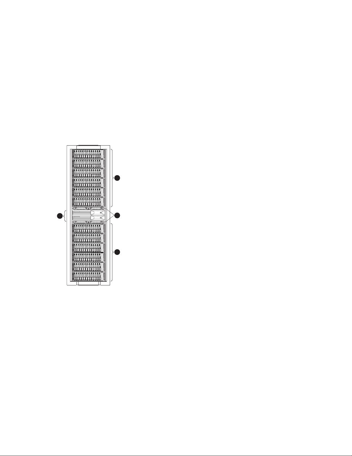
The basic physical components are shown in Figure 1. The disk drives are installed in the disk enclosures,
which connect to Fibre Channel (FC) loop switches. The controller pair also connects to the FC loop
switches.
ental Monitoring Unit (EMU).
r—Manages all aspects of storage system operation, including communications
ystems and other devices. A pair of HSV controllers is included in Enterprise
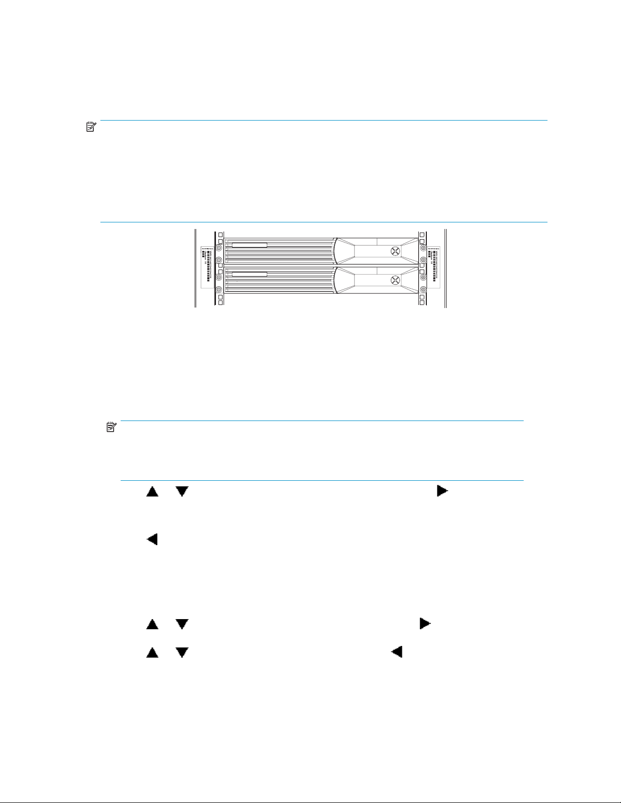
3
1
CXO7941
Figure 1 Storage system h ardware components
1. Drive enclosures 2. FC switches
3. Controllers
The hardware components shown in Figure 1 are discussed in the following sections and in Storage
System Hardware Components.
Fibre Channel drive enclosure
Each Fibre Channel drive enclosure includes the following features. For additional information, see
Fibre Channel drive enclosures.
• 3U enclosure
• Dual-redundant, active-to-active, 2–Gbps FC loops
• Fourteen bays for 1–inch FC disks
2
3
Enterprise Virtual Array 3000/5000 user guide
19
Page 20

• Environmental Monitoring Unit (EMU)
• Dual 2–Gbps FC I/O modules—A and B loops
• Dual redundant 500W power supplies and blowers
• Dual redundant blowers
For ease of management, the disk drives are referred to by their physical location, the drive bay number.
Fibre Channel loop switches
The Fibre Channel loop switch acts as a central point of interconnection and establishes a fault-tolerant
physical loop topology between the controllers and the disk enclosures. The EVA5000 uses four loop
switches to co
The FC loop switches provide the following features. For detailed information on Fibre Channel loop
switches, see Fibre Channel loop switches.
• 2.125–Gbps o
• Twelve ports
• Half-width, 1U size
• System and p
• Universal power supply that operates between 100 to 250 VAC and 50 to 60 Hz
NOTE:
Each bezel covers two FC loop switches in a space of 1U.
nnect the drive enclosures to the controller pair.
perating speed
ort status indicators
HSV110 and HSV100 controllers
Two controllers are contained in each rack. Each controller is c ontained in a separate enclosure and
provides the features listed below. For detailed information, see HSV controllers.
• High-performance microprocessor
• An Operator Control Panel (OCP)
• Two 2–Gbps Fibre Channel-Switched fabric host ports
• Four 2–Gbps Fibre Channel drive enclosure device ports (two device ports in HSV100 controller)
• Arranged in redundant pairs
• Data load/performance balanced across a pair
• S uppor t for up to 240 disks with HSV110 and 56 with HSV100
• 1.25 GB cache per controller, mirrored, with battery backup
• 2–GBpsFCcachemirroringportswithdeviceportbackups
• Dual power supplies
In addition to managing the operation of the storage system, the HSV controllers serve as the interface
between the storage system hardware and the SAN. All host I/Os and all HP Command View EVA
management commands are processed by the controllers. Up to 18 drive enclosures are supported
by one controller pair.
NOTE:
To avoid impacting Secure Path operation, the internal identification of the controllers has been changed
for VCS v4.001. For VCS v4.001 and later firmware, the EVA3000 controller is now identified as
HSV101 and the EVA5000 controller is identified as HSV111.
20
Enterprise Virtual Array description
Page 21

Racks
The rack provides the capability for mounting standard 483 mm (19 in) wide controller and drive
enclosures. For additional information, see Racks.
The following racks are available:
• 22U Rack
• 25U Rack
• 33U Rack
• 36U Rack
• 41U Rack
• 42U Rack
• Universal Ra
NOTE:
Racks and rack-mountable components are typically described using “U” measurements. “U”
measurements are used to designate panel or enclosure heights.
Theracksprovidethefollowing:
• Unique frame and rail design—Allows fast assembly, easy mounting, and outstanding structural
integrity.
• Thermal integrity—Front-to-back natural convection cooling is greatly enhanced by the innovative
multi-angled design of the front door.
• Security provisions—The front and rear door are lockable, which prevents unauthorized entry.
• Flexibility—Provides easy access to hardware components for operation monitoring.
• Custom expandability—Several options allow for quick and easy expansion of the racks to
create a custom solution.
ck
Enterprise Virtual Array 3000/5000 user guide
21
Page 22

22
Enterprise Virtual Array description
Page 23

2 Enterprise Virtual Array startup
This chapter describes the procedures necessary to complete the installation and configuration of the
Enterprise Virtual Array. When these procedures are complete, you can begin using your storage system.
NOTE:
InstallationoftheEnterpriseVirtualArrayshouldbedoneonlybyanHPauthorizedservice
representative. The information in this chapter provides an overview of the steps involved in the
installation and configuration of the storage system.
This chapter consists of:
• Storage system connections
• Procedures for getting started
• G athering information
• Setting up the storage system hardware
• Entering data using the Operator Control Panel (OCP)
• Installing HP Command View EVA
EVA5000 storage system connections
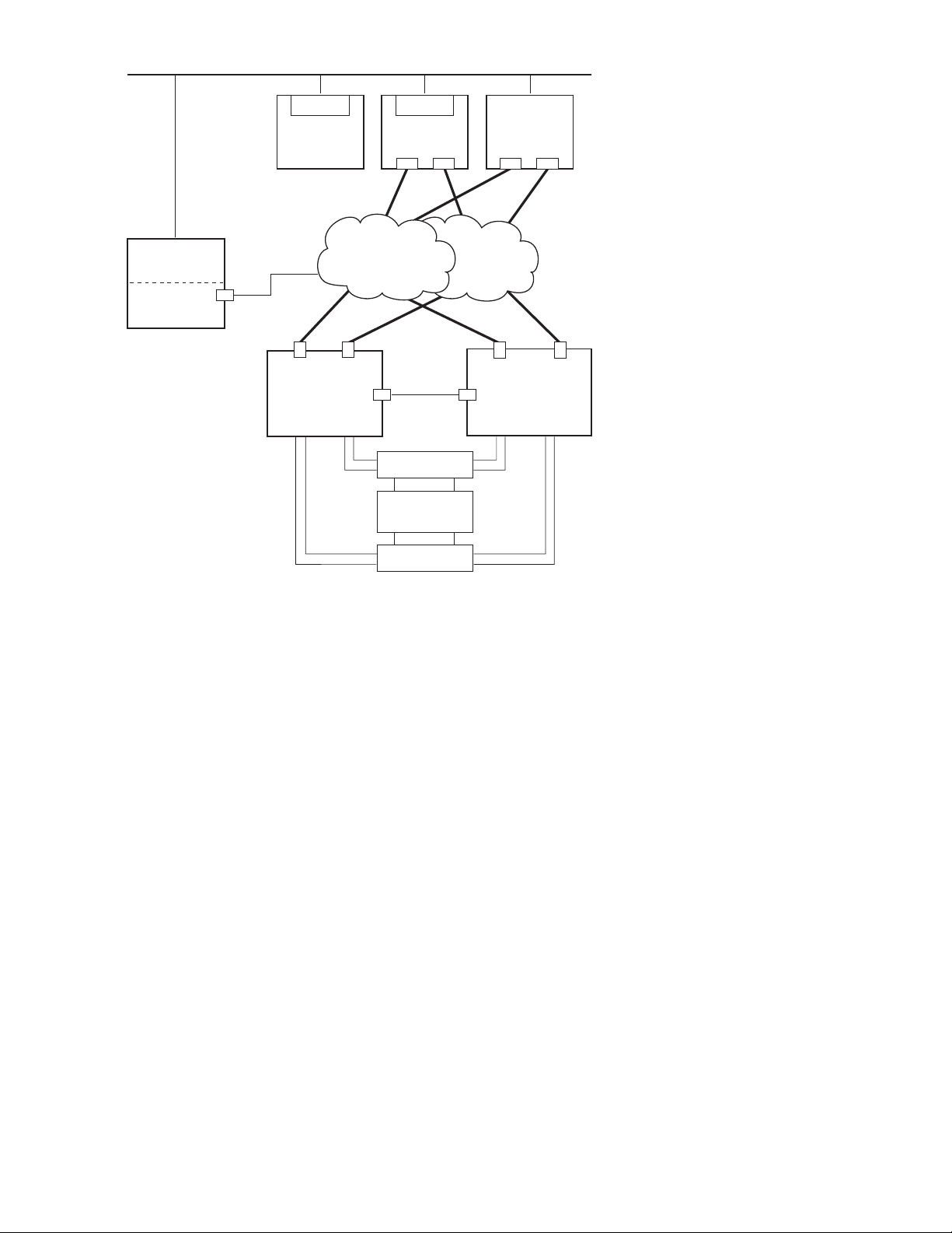
Figure 2 shows a typical EVA5000 SAN topology:
• The HSV110 controllers connect via two host ports (FP1 and FP2) to the Fibre Channel fabrics.
The hosts that will access the storage system are connected to the same fabrics.
• The HP Command View EVA management server also connects to the fabric.
• The controllers connect through two lo op pairs to the drive enclosures. Each loop pair consists of
two independent loops, each capable of managing all the disks should one loop fail. Four FC
loop switches are used to connect the controllers to the disk enclosures.
Enterprise Virtual Array 3000/5000 user guide
23
Page 24
B
Browser
Network Interconnection
F
F
Non-Host
Browser
Host X
FCA
FCA FCA FCA
Host Z
Management
Server
Command
View EVA
P = Fibre (Host) Port
CA = Fibre Channel Adapter
Figure 2 EVA5000 configuration
EVA3000
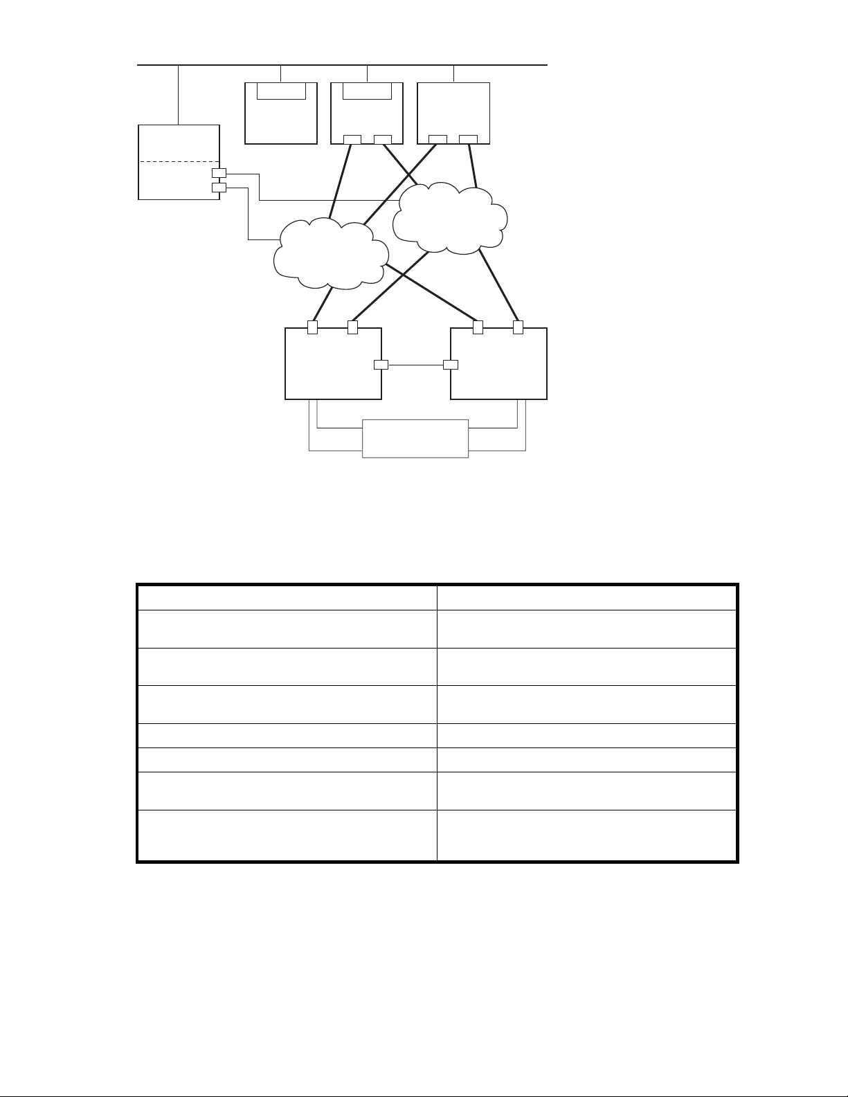
Figure 3 shows a typical EVA3000 SAN topology:
• The HSV100 controllers connect via two host ports (FP1 and FP2) to the Fibre Channel fabrics.
The hos
• The HP Command View EVA m ana gement ser ver also connects to the fabric.
• The controllers connect through one loop pair to the drive enclosures. The loop pair consists of
two independent loops, each capable of managing all the disks should one loop fail. The
contr
Fabric 2Fabric 1
FP1 FP2
Controller
A
Loop
Pair 1
Loop
Pair 2
Cache
Mirror Port
FC Loop Switches
A
Drive Enclosures
A
FC Loop Switches
B
B
FP1 FP2
Controller
B
Loop
Pair 2
Loop
Pair 1
CXO7947
storage system connections
ts that will access the storage system are connected to the same fabrics.
ollers connect directly to the disk enclosures.
24
Enterprise Virtual Array startup
Page 25
Management
a
Network Interconnection
F
F
Server
Command
View EVA
Browser
Non-Host
Fabric 1
Browser
Host X
FCA
FCA FCA FCA
Host Z
Fabric 2
FP1 FP2
Controller
A
Loop
Pair 1
B
A
P = Fibre (Host) Port
CA = Fibre Channel Adapter
Figure 3 EVA3000 configuration
Procedures for getting started
Step
1. Gather information and identify all related storage
documentation.
2. Contact an authorized service representative for
hardware configuration information.
3. Enter the World Wide Name (WWN) into the
OCP.
4. Confi
5. Prepare the hosts.
6. Configure the system through HP Command View
EVA.
7. Make virtual disks available to their hosts. Refer to
the storage system software documentation for each
host’s operating system.
gure HP Command View EVA.
Cache
Mirror Port
Drive Enclosures
FP1 FP2
Controller
B
Loop
Pair 1
B
A
25060
Custome
r
Customer
HP Service Engineer
HP Service Engineer
Customer
HP Service Engineer
vice Engineer
HP Ser
Responsibility
Gathering information
The following items should be available when installing and configuring an Enterprise Virtual Array . They
provide information necessary to set up the storage system successfully.
• HP StorageWorks Enterprise Virtual Array 3000/5000 release notes.
Enterprise Virtual Array 3000/5000 user guide
25
Page 26
• HP StorageWorks Enterprise Virtual Array 3000/5000 read me first.
• HP StorageWorks Enterprise Virtual Array 3000/5000 World Wide Name label,whichis
shipped with the storage system
• The latest HP OpenView Storage Management Server Update, which consists of the management
server update CD and its associated documentation, or the latest Windows Server Update
• You can determine the latest update version available by checking the release notes or
contacting your authorized service representative to findouthowtoreceivethelatest
information.
• Additional documentation is available from the following HP web sites:
• h
• http://www.hp.com/go/eva5000
Locate these items and keep them handy. You will need them for the procedures in this manua l.
Host information
Make a list o
the follow
• TheLANnameofthehost
• A list of World Wide Names of the FC adapters, also called host bus adapters, through which
the host will connect to the fabric or fabrics that provide access to the storage system
• Operatin
• Available LUN numbers
ttp://www.hp.com/go/eva3000
f information for each host computer that will be accessing the storage system. You will need
ing information for each host:
gsystemtype
Setting up a controller pair using the OCP
NOTE:
ThisprocedureshouldbeperformedbyanHPauthorizedservicerepresentative.
Two pieces of data must be entered during initial setup using the controller OCP:
• World Wide Name (WWN)—Required to complete setup. This procedure should be performed
by an HP authorized service representative.
• Storage system p assword—Optional. A password provides security allowing only specific
instances of HP Command View EVA to access the storage system.
The OCP on either controller can be used to input the WWN and password data. For more information
about the OCP, see "Operator Control Panel" on page 68.
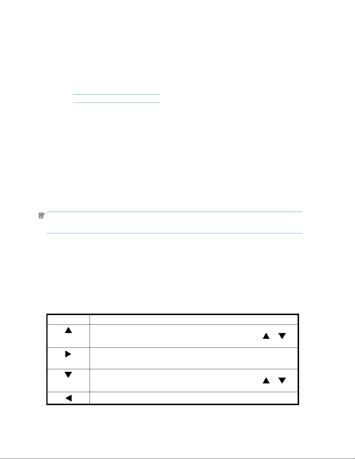
Table 2 lists the push button functions when entering the WWN, WWN checksum, and password data.
Table 2 WWN push button functions
Button
Selects a WWN or checksum character by scrolling up through the character list one
character at a time. If you select an incorrect character, you can use either
select the correct character.
Accepts the current character and selects the next character. If you accept an incorrect
character, you can move through all 16 characters, one character at a time, until you
display the incorrect character. You can then change the character.
Function
or to
Selects a WWN or checksum character by scrolling down through the character list one
character at a time. If you select an incorrect character, you can use either
the select correct character.
Accepts all the WWN or checksum characters.
26
Enterprise Virtual Array startup
or to
Page 27
Entering the WWN
C
Fibre Channel protocol requires that each controller pair have a unique WWN. This 16-character
alphanumeric name identifies the controller pair on the storage system. Two WWN labels attached to the
rack identify the storage system WWN and checksum. See Figure 4.
NOTE:
• TheWWNisuniquetoacontrollerpairandcannotbeusedforanyothercontrollerpairordevice
anywhere on the network.
• This is the onl
replacement controller.
• Once a WWN is assigned to a controller, you cannot change the WWN while the controller is part
of the same storage system.
Complete the following procedure to assign the WWN to each pair of controllers.
y WWN applicable to any controller installed in a specificphysicallocation,evena
CXO7601
Figure 4 Location of the World Wide Name labels
1. Turn the power switches on both controllers off.
2. Apply power to the rack.
3. Turn the power switch on both controllers on.
NOTE:
Notifications of the startup test steps that have been executed are displayed while the
controller is booting. It may take up to two minutes for the steps to display. The default
WWN entry display has a 0 i n each of the 16 positions.
4. Press or until the first character of the WWN is displayed. Press to accept this character
and select the next.
5. Repeat the p receding step to enter the remaining characters.
o accept the WWN and select the checksum entry mode.
6. Press
t
Entering the WWN checksum
The second p art of the WWN entry procedure is to enter the two-character checksum, as follows.
1. Verify that the initial WWN checksum displays 0 in both positions.
2. Press
select the second character.
3. Press
4. Verify that the default display is automatically selected. This indicates that the checksum is valid.
or until the first checksum character is displayed. Press to accept this character and
or until the second character is displayed. Press to accept the checksum and exit.
Enterprise Virtual Array 3000/5000 user guide
27
Page 28
NOTE:
If you enter an incorrect WWN or checksum, the system will reject the data and you must repeat the
procedure.
Entering the storage system password
The eight-character storage system password feature enables you to restrict management access to the
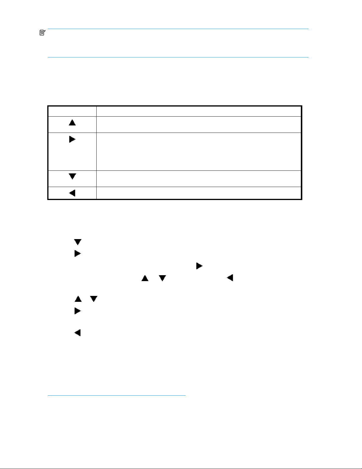
storage system. Table 3 describes the push button functions when using the password feature.
Table 3 System password push button functions
Button
Selects a password character by scrolling up through the character list one character
at a time.
• Movesfromthedefaultdisplaytothesystemmenutree.
• Moves from the system password display to the password entry display.
• Accepts the current character and selects the next character.
If you accept an incorrect character, you can loop through the display, one position at
time, to select the character to be changed.
Selects a password character by scrolling down through the character list one character
at a time.
Accepts all the password characters.
Function
Complete the following procedure to set the password:
1. Select a unique eight-character password using uppercase or lowercase letters A through Z.
2. From the default menu, press any push button to select the menu tree.
3. Press
4. Press
5. When the System Password function is flashing, press
6. To change the password, press
to cycle through the displays until System Password is displayed.
to select the system password function.
to select the change password function.
or to show Yes and press .
The default Enter Password function displays the default password, AAAAAAAA.
7. Press
8. Press
or until the first character of the password is displayed.
to accept this character and select the next character.
9. Repeat the process to enter the remaining password characters.
10. Press
to enter the password and return to the default menu display.
The controller pair setup is complete.
Installing HP Command View EVA
HP Command View EVA is installed on the HP Op enView Storage Management Server or a
Windows host and runs in the OpenView environment. Installation may be skipped if the latest
version of HP Command View EVA is running. Verify the latest version at the HP web site:
ttp://h18006.www1.hp.com/storage/software.html.
h
To install a new version, locate the management server update CD-ROM and the associated
documentation that was shipped with your storage system. Follow the instructions in the HP OpenView
Storage Management Server update installation card to install the new software.
28
Enterprise Virtual Array startup
Page 29

Installing opti
onal EVA software licenses
If you purchase
available for the Enterprise Virtual Array includes HP Business Copy and HP Continuous Access.
Installation instructions are included with the license.
doptionalEVAsoftware,itwillbenecessarytoinstallthelicense. Optionalsoftware
Enterprise Virtual Array 3000/5000 user guide
29
Page 30

30
Enterprise Virtual Array startup
Page 31

3 Enterprise Virtual Array
operation
This chapter presents the tasks that you might need to perform during normal operation of the storage
system.
Best practices
For useful information on managing and configuring your storage system, refer to the HP
StorageWorks Enterprise Virtual Array configuration best practices white paper available from
h
ttp://h71028.www7.hp.com/ERC/downloads/5982-9140EN.pdf.
Operating tips and information
Reserving adequate free space
To ensure efficient storage system operation, a certain amount of unallocated capacity, or free space,
should be reserved in each disk group. The recommended amount of free space is influenced by your
system configuration. For guidance on how much free space to reserve, refer to the HP StorageWorks
Enterprise Virtual Array configuration best practices white paper. See Best practices.
Using FATA disk drives
FATA drives are designed for lower duty cycle applications such as near on-line data replication for
back-up. These drives should not be used as a replacement for EVA’s high performance, standard
duty cycle, Fibre Channel drives. Doing so could shorten the life of the drive. Download the following
document for more information on FATA drives, their uses and benefits:
ttp://h71028.www7.hp.com/ERC/downloads/5982-7353EN.pdf
h
Failback preference setting for HSV controllers
Table 4 describes the failback preference mode for each of the operating systems supported with HSV
controllers and Command View EVA.
Table 5
indicates when Secure Path is used in conjunction with the operating system
describes the failback default behavior and settings allowed for each operating system. The table
Enterprise Virtual Array 3000/5000 user guide
31
Page 32

Table 4 Failback preference settings
Setting Point in time
No preference
Path A - Failover
Only
At initial pres
On dual boot or controller resynch
On controller failover
On controller failback
At initial presentation The units are brought online to Controller
On dual boot or controller resynch
On contr
On controller failback
oller failover
entation
Behavior
The units are al
to Controller
If cache data for a LUN exists on a
particular controller, the unit will be
brought online there. Otherwise, the
units are alternately brought online to
Controller A or to Controller B.
All LUNs are brought online to the
surviving controller.
All LUNs rem
controller. There is no failback except
if a host moves the LUN using SCSI
commands.
A.
If cache data for a LUN exists on a
particular controller, the unit will be
brought online there. Otherwise, the
units are brought online to Controller A.
All LUNs are brought online to the
surviving controller.
All LUNs remain on the surviving
controller. There is no failback except
if a host moves the LUN using SCSI
commands.
ternately brought online
AortoControllerB.
ain on the surviving
Path B - Failover Only
At initial presentation The units are brought online to Controller
On dual boot or controller resynch
On controller failover
On controller failback
B.
he data for a LUN exists on a
If cac
icular controller, the unit will be
part
ght online there. Otherwise, the
brou
s are brought online to Controller B.
unit
All LUNs are brought online to the
surviving controller.
All LUNs remain on the surviving
controller. There is no failback except
if a host moves the LUN using SCSI
commands.
32
Enterprise Virtual Array operation
Page 33

Setting Point in time
Behavior
Path A - Failover/
Failback
Path B - Failover/
Failback
At initial presentation The units are brought online to Controller
On dual boot or controller resynch
On controller failover
On controller failback
At initia
On dual boot or controller resynch
On controller failover
l presentation
A.
If cache data fo
particular co
brought onlin
units are brou
All LUNs are brought online to the
surviving controller.
AllLUNsremainonthesurviving
controller. After controller restoration,
the units that are online to Controller B
and set to Path A are brought online
toControllerA.Thisisaonetime
occurrence. If the host then moves the
LUN using SCSI commands, the LUN will
remain where moved.
The units
B.
If cache data for a LUN exists on a
particular controller, the unit will be
brought online there. Otherwise, the
units are brought online to Controller B.
All LUNs are brought online to the
surviving controller.
raLUNexistsona
ntroller, the unit will be
ethere. Otherwise,the
ght online to Controller A.
are brought online to Controller
On controller failback
All LUN
controller. After controller restoration,
the units that are online to Controller
A and set to Path B are brought online
toControllerB.Thisisaonetime
occurrence. If the host then moves the
LUN using SCSI commands, the LUN will
remain where moved.
sremainonthesurviving
Enterprise Virtual Array 3000/5000 user guide
33
Page 34

Table 5 Failback Settings by Operating System
Operating system
HP-UX
Tru64 UNIX
OpenVMS (7.3-
Windows®
Sun Solaris®
IBM AIX
Linux
Novell NetWare
VMware
1andgreater)
Default behavior
Autoback done by the host
Host follows the unit
Host follows the unit
Auto failback done by the host No Preference, Path A/B - Failover
Auto failback done by the host No Preference, Path A/B - Failover
Auto failback done by the host No Preference, Path A/B - Failover
Auto failback done by the host No PreferencePath A/B - Failover
Auto failback done by the host No PreferencePath A/B - Failover
Auto failback done by the host No PreferencePath A/B - Failover
Settings supported
No Preference, Path A/B - Failover
Only.
All settings allowed.
Recommended setting: Path
A/B - Failover/Failback.
All settings a
Recommended
A/B - Failover/Failback.
Only.
Only.
Only.
Only
Only
Only
llowed.
setting: Path
Changing virtual disk failover/failback setting
Changing the failover/failback setting of a virtual disk may impact which controller presents the disk.
Table 6 identifies the presentation behavior that results when the failover/failback setting for a virtual
disk is c
NOTE:
If the new setting causes the presentation of the virtual disk to move to a new controller, any snapshots
or snapclones associated with the virtual disk will also be moved.
Table 6 Impact on virtual disk presentation when c h angin g failover/failback setting
New setting
No Preference
Path A Failover
Path B Failover
Path A Failover/Failback If the disk is currently presented on controller B, it is moved to
Path B Failover/Failback If the disk is currently presented on controller A, it is moved to
hanged.
Impact on virtual disk presentation
None. The disk maintains its original presentation
If the disk is currently presented on controller B, it is moved to
controller A. If the disk is on controller A, it remains there.
If the disk is currently presented on controller A, it is moved to
controllerB.IfthediskisoncontrollerB,itremainsthere.
controller A. If the disk is on controller A, it remains there.
controllerB.IfthediskisoncontrollerB,itremainsthere.
34
Enterprise Virtual Array operation
Page 35

Storage system s
hutdown and powerup
The storage sys
following func
1. Flushes cache
2. Removes power from the controllers
3. Disables cach
4. Removes power from the drive enclosures
5. Disconnects the system from HP Command View EVA
NOTE:
The storage s
shutdown whe
are used, or
tem is shut down using HP Command View EVA. The shutdown process performs the
tions in the indicated order:
e battery power
ystemmaytakealongtimetocompletethenecessarycacheflush during controller
n snapshots are being used. The delay may be particularly long if multiple child snapshots
if there has been a large amount of write activity to the snapshot source Vdisk.
Shutting down the storage system
To shut the storage system down, per form the following steps:
1. Start HP Command View EVA.
2. Select the appropriate storage system in the Navigation pane.
The Initialized Storage System Properties window for the selected storage system opens.
3. Click System options.
The System Options window opens.
4. Click Shut down.
The Shutdown Options window opens.
5. Under System Shutdown click Power Down. If you want to delay the initiation of the shutdown, enter
the number of minutes in the Shutdown delay field.
The controllers complete an orderly shutdown and then power off. The disk enclosures then power
off. Wait for the shutdown to complete.
6. Turn off the power switch on the rear of each HSV controller.
7. Turn off the circuit breakers on both of the EVA rack Power Distribution Units (PDU).
8. If your management server is an SMA and you are not using it to manage other storage arrays, shut
down the SMA. From the SMA user interface, click Settings > Maintenance > Shutdown.
Powering up the storage system
To power up a storage system, perform the following steps:
1. Verify that each fabric Fibre Channel switch to which the HSV controllers are connected is powered
up and fully booted. The power indicator on each switch should be on.
If you must power up the SAN switches, wait for them to comp lete their power-on boot process
before proceeding. This may take several minutes.
2. If the management server you shut down is an SMA, power it o n and wait for it to completely b oot.
Verify the SMA is running by logging into it using the web interface.
Enterprise Virtual Array 3000/5000 user guide
35
Page 36

NOTE:
Before applying power to the rack, ensure that the power switch on each HSV controller
is off.
3. PoweronthecircuitbreakersonbothEVArackPDUs.Verifythatalldriveenclosuresareoperating
properly. The status indicator and the power indicator should be on (green).
4. Wait three minutes and then verify that all disk drives are ready. The drive ready indicator and
the drive online indicator should be on (green).
5. Power on the upper controller. It takes the roll of master controller.
6. Wait 10 seconds and then power on the lower controller. It takes the roll of slave controller.
7. Verify that the (Operator Control Panel) OCP display on each controller displays the storage system
name and the EVA WWN.
8. Start HP Command View EVA and verify connection to the storage system. If the storage system is
not visible, click HSV Storage Network in the N avigation pane then click Discover in the Content
pane to discover the array.
NOTE:
If the storage system is still not visible, reboot the management server to re-establish the
communication link.
9. Check the s
properly
service p
torage system status using HP Command View EVA to ensure everything is operating
. If any status indicator is not normal, check the log files or contact your HP—authorized
rovider for assistance.
Saving storage system configuration data
As part of an overall data protection strategy, storage system configuration data should saved during
initial installation, and whenever major configuration changes are made to the storage system. This
includes adding or removing disk drives, creating or deleting disk groups, and adding or deleting virtual
disks. The saved configuration data can save substantial time should it ever become necessary to
re-initialize the storage system. The configuration data is saved to a series of files stored in a location
other than on the storage system.
This procedure can be performed from the SAN Management Appliance (SMA) or management server
where the Command View EVA application is installed, or any host that can run the Storage System
Scripting Utilit y (SSSU) to communicate with the Command View EVA application server.
NOTE:
SSSU version 4 is required for HP Command View EVA 4.0 and later. For more information on using
SSSU, refer to the
from the following web site:
ttp://h18006.www1.hp.com/products/storage/software/cmdvieweva/index.html
h
Click Support & Documentation.
HP StorageWorks Storage System Scripting Utility reference
, which can be downloaded
1. Run SSSU on the platform and operating system of your choice.
2. Enter SELECT MANAGER and select the management server.
3. Enter SHOW SYSTEM to determine which storage systems are managed by this instance of HP
Command View EVA.
4. Enter SELECT SYSTEM to select the appropriate storage system from which to collect configuration
data.
36
Enterprise Virtual Array operation
Page 37

5. Enter CAPTURE CONFIGURATION, specifying the full path and fi lename of the output files for
the configu ration data.
The configuration data is stored in a series of from one to five files, which are SSSU scripts. The
file names begin with the name you choose, with the restore step appended. For example,
if you specify a file name of LargeEVA.txt,theresultantconfiguration files would be
LargeEVA_Step1A.txt, LargeEVA_Step1B,etc.
The contents of the configuration files can be viewed with a text editor.
NOTE:
If the storage system contains disk drives of different capacities, the SSSU procedures used do not
guarantee that disk drives of the same capacity will be exclusively added to the same disk group. If you
need to restore an array configuration that contains disks of different sizes and types, you must manually
recreate these disk groups. The controller software and the utility’s CAPTURE CONFIGURATION
command are not designed to automatically restore this type of configuration. For more information,
refer to the
HP StorageWorks Storage System Scripting Utility reference
.
The following examples illustrate how to save and restore the storage system configuration data using
SSSU on a Windows host.
Example 1. Saving configuration data using SSSU on a Windows Host
Run SSSU from a DOS Command Window on the SMA, a Windows Workstation or a Windows Server
that can access the SMA by TCP/IP or the management host running Command View.
1. Click Run on the Window Start menu.
2. Enter cmd in the Open field to open the DOS Command Window.
3. Change to the directory (CD) in which you have installed SSSU. For example, C:> cd \SSSUDir
4. Enter SSSU to run the application.
5. Enter SELECT MANAGER <SMAname or ip_addr> user=<username> pass=<userpass-
word>.
6. Enter SHOW SYSTEM to display the EVA storage systems managed by the SMA or Windows Host.
7. Enter SELECT SYSTEM <EVA_Name>,whereEVA_name isthenameofthestoragesystem.
The storage system name is case sensitive. If there are spaces between the letters in the name, quotes
must enclose the name. For example, SELECT SYSTEM “Large EVA”.
8. Enter CAPTURE CONFIGURATION <pathname\filename>,wherepathname identifies the
location where the configuration files will be saved, and filename isthenameusedastheprefixfor
the configurations files. For example, CAPTURE CONFIGURATION c:\EVAConfig\LargeEVA
9. Enter EXIT to close the DOS Command Window.
Example 2. Restoring configura tion data using SSSU on a Windows Ho s t
If it is necessary to restore the storage system configuration, it can be done using the
1. Click Run on the Window Start menu.
2. Enter cmd in the Open field to open the DOS Command Window.
3. Change to the directory (CD) in which you have installed SSSU. For example, C:> cd \SSSUDir
4. Enter SSSU to run the application.
5. Enter FILE <pathname\filename>,wherepathname identi
fies the location where the
configuration files are be saved and filename is the name of the first configuration file. For example,
FILE c:\EVAConfig\LargeEVA_Step1A.txt
6. Repeat the preceding step for each configuration file.
Enterprise Virtual Array 3000/5000 user guide
37
Page 38

Adding disk driv
As your storage requirements grow, you may be adding disk drives to your storage system. Adding new
disk drives is the easiest way to increase the storage capacity of the storage system. Disk drives can be
added online without impacting storage system operation.
es to the storage system
Guidelines for adding disk drives
When adding new disk drives to the storage system, you should ensure that the disk drives are installed
in the correct positions to maintain availability. The disk drives should be distributed across the disk
enclosures to protect against the failure of a sing l e disk enclosure.
Use the following guidelines when adding disk drives to your storage system:
• Install high performance and FATA disk drives in separate groups. These different drive types must
be in separate d isk groups. You may also want to consider separating different drive capacities
and spindle speeds into different groups.
• Thediskdrivesshouldbedistributedevenlyacrossthediskenclosures.Thenumberofdisksof
a given type in each enclosure should not differ by more than one. For example, no enclosure
should have two disks until all the other enclosures have at least one.
• Disk drives should be installed in vertical columns within the disk enclosures. Add drives vertically
in multiples of eight, completely filling columns if possible. Disk groups are more robust if filled
with the same number of disk drives in each enclosure. See Figure 6 for an example.
NOTE:
When adding multiple disk drives, add a disk and wait for its activity indicator ( 1) to stop flashing
(up to 90 seconds) before installing the next disk (see Figure 5). Thisproceduremustbefollowedto
avoidunexpectedEVAsystembehavior.
Figure 5 Disk drive activity in dica tor
Creating disk groups
Thenewdisksyouaddwilltypicallybeusedtocreatenewdiskgroups. Althoughyoucannotselect
which disks will be part of a d isk group, you can control this by building the disk groups sequentially.
Add the disk drives required for the first disk group, and then create a disk group using these disk drives.
Now add the disk drives for the second disk group, and then create that disk group. This process gives
you control over which disk drives are included in ea ch disk group. Figure 6 shows the sequential
building of vertical disk groups.
38
Enterprise Virtual Array operation
Page 39

NOTE:
Standard and FATA disk drives must be in separate disk groups. Disk drives of different capacities and
spindle speeds can be included in the same disk group, but you may want to consider separating
them into separate disk groups.
Figure 6 Sequential building of vertical disk groups
1. Disks installed in first group
2. Disks installed in second group
Adding a disk drive
This section describes the procedure for adding a Fibre Channel disk drive.
Removing the drive blank
1. Grasp the drive blank by the two mounting tabs (see Figure 7).
2. Lift up on the lower mounting tab and pull the bla nk out of the enclosure.
21
CX8167-ST
Enterprise Virtual Array 3000/5000 user guide
39
Page 40

˚
2
1
CXO7359B
Figure 7 Removing the drive blank
1. Upper mounting tab 2. Lower mounting tab
Changing the Device Addition Policy
To prevent the storage system from automatically grouping a new disk drive tha t m ay have the incorrect
firmware on it, the Device Addition Policy must be checked and set to manual if ne cessar y:
1. Open Command View VA and in the Navigation pane select the storage system.
The Initialized Storage System Properties window opens.
2. Click System Options
3. Select Set system operational policies
4. IftheDeviceAdditionPolicyissettoAutomatic, change it to Manual
5. Click Save changes
Installing the disk drive
1. Push in t
he ejector button on the disk drive and pull the release lever down to the full open position.
2. Insertthedriveintotheenclosureasfarasitwillgo(1,Figure 8).
3. Close the release lever until it engages the ejector button, and the disk drive seats in the backplane
(2, Figu
4. Press i
re 8).
n firmly on the disk drive to ensure it is seated properly.
1
2
Figure 8 Insta lling the disk drive
Checking status indicators
After replacing the disk drive, check the following to verify that the disk drive is operating normally:
0116a
40
Enterprise Virtual Array operation
Page 41

NOTE:
It may take up to 10 minutes for the component to display good status.
• Check the disk drive status indicators. See Figure 9.
•Activityindicator(1)shouldbeonorflashing
• Online indicator (2) should be on or flashing
• Fault indicator (3) should be off
• Check the following using Command View EVA.
• N avigate to the disk drive and check the operational state. It should be
.
•RecordtheModel number and the Firmware version.Checkthefirmware version against the
supported disk firmware in the HP StorageWorks Enterprise Virtual Array release notes.The
most current edition of the release notes can be downloaded from the following web site:
h
ttp://www.hp.com/go/eva5000
Click Technical documentation.
If the disk drive is using an unsupported version of firmware, download the correct firmware
from the following web site and install it using the instructions included with the firmware file.
Use the d isk drive model number to locate the correct firmware file. Do not add the disk drive
to a disk group if it using an unsupported firmware version.
h
ttp://www.hp.com/support/evadiskfirmware
Figure 9 Disk drive status indicators
1. Activity
3. Fault
Adding the disk to a disk group
After replacing the disk, it should be added to a disk group.
1. In the Navigation pane, select Storage system > Hardware > Rack > Disk enc losu re > Bay
2. In the Content pane, select the Disk Drive tab.
3. Click Group to initiate the process for adding the disk to a disk group.
NOTE:
If the Device Addition Policy is set to automatic, the disk will automatically be added to a disk group. In
this case the Group option will not be available.
2. Online
Enterprise Virtual Array 3000/5000 user guide
41
Page 42

Handling fiber o
ptic cables
This section pr
Contamination
the transmission of data. Therefore, protecting the connector tips against contamination or damage
is imperative. The tips can be contaminated by touching them, by dust, or by debris. They can be
damaged when d
covers or dust
are installed whenever the transceivers or cables are disconnected. Clea ning the connectors should
remove contamination.
The transcei
CAUTION:
To avoid da mage to the connectors, always install the dust covers or dust caps whenever a transceiver
or a fiber cable is disconnected. Remove the dust covers or dust caps from transceivers or fiber cable
connectors only when they are connected. Donotdiscardthedustcovers.
To minimize the risk of contamination or damage, do the following:
• Dust covers—Remove and set aside the dust covers and dust caps when installing a n I/O module,
a transceiver or a cable. Install the dust covers when disconnecting a transceiver or cable.
• When to clean—If a connector may be c ontaminated, or if a connector has not been protected by
a dust cover for an extended p eriod of time, clean it.
• How to clean:
1. Wipe the connector with a lint–free tissue soaked with 100% isopropyl alcohol.
ovides protection and cleaning methods for fiber optic connectors.
of the fiberopticconnectorsoneitheratransceiveroracableconnectorcanimpede
ropped. To protect the connectors against contamination or damage, use the dust
caps provided by the manufacturer. These covers are removed during installation, and
ver dust caps protect the transceivers from contamination. Donotdiscardthedustcovers.
2. Wipe the connector with a dry, lint–free tissue.
3. Dry the connector with moisture-free compressed air.
One of the many sources for cleaning equipment specifically designed for fiber optic connectors is:
AlcoaFujikuraLtd.
1-888-385-4587 (North America)
011-1-770-956-7200 (International)
42
Enterprise Virtual Array operation
Page 43

4 Enterprise Virtual Array
hardware components
This chapter describes the Enterprise Virtual Array hardware components. Topics to be discussed include:
• Fibre Channel drive enclosures
• Fibre Channel loop switches
• HSV controllers
•Racks
Fibre Chann
The drive enclosure contains the disk drives used for data storage. A storage system includes multiple
drive enclosures. The major components of the enclosure are:
• 2.125–Gb, dual loop, 14–drive enclosure
• Dual-loop,
• Copper Fibre Channel cables
• Fibre Channel disk drives and drive blanks
• Power supp
• Blowers
• Cache batteries
• EMU
Enclosure layout
The disk drives mount in bays in the front of the enclosure. The bays are numbered sequentially from left
to right. A drive is referred to by its bay number. Enclosure status indicators are located in the lower-right,
front corner. Figure 10 shows the front and rear views of the FC drive enclosure.
el drive enclosures
Fibre Channel drive enclosure I/O modules
lies
Enterprise Virtual Array 3000/5000 user guide
43
Page 44

1
Front
2
10
Figure 10 FC drive enclosure—front and rear views
1. Drive bay 1 2. Drive bay 14
3. EMU
5. Blower 1 6. Power supply 1
7. Blower 2 8. Power supply 2
9. I/O modu le A
I/O modules
Two I/O m
11.They
For redundancy, only dual-controller, dual-loop operation is supported. Each controller is connected to
both I/O modules in the drive enclosure.
Rear
4
3
56 78 9
10
0112a
4. I/O module B
10. Status indicators (EMU, enclosure p ower,
enclosure fault)
odules provide the interface between the drive enclosure and the host controllers. See Figure
route data to and from the disk drives using Loop A and Loop B, the dual-loop configuration.
44
Enterprise Virtual Array hardware components
Page 45

2
A
1
3
0107a
Figure 11 I/O module
1. Status indicators (Upper port, Power, and Lower port)
2. Upper port
3. Lower po
rt
The I/O modules are functionally identical, but are not interchangeable. Module A can only be installed
at the right end of the enclosure, and module B can only be installed at the left end of the enclosure. See
Figure 10
Each I/O m
.
odule has two ports that can both transmit and receive data for bidirectional operation.
Activating a por t requires connecting a FC cable to the port. The port function depends upon the
loop. See Figure 12.
4 2
3 1
Figure
1. Loop A lower port
3. Loo
12 Input and output ports
pBlowerport
I/O module status indicators
There are three status indicators on the I/O module. See Figure 11. The status indicator states for
an operational I/O module are shown in Table 7. Table 8 shows the status indicator states for a
non-operational I/O module.
CXO7954
2. Loop A upper port
4. Loop B upper port
Enterprise Virtual Array 3000/5000 user guide
45
Page 46

Table 7 Operational I/O module status indicators
Upper Power Lower
Off
On
On On On
Flashing Flashing Flashing
Table 8 N
on-operational I/O module status indica tors
On
Flashing, then On
Upper Power Lower
On On
Off
Descriptions
Off
On
• I/O Module is op
• Top por t—Fibre Channel drive enclosure signal detected.
• Power—Flashes for about 90 seconds after initial power application,
then remains constant.
• Bottom port—Fibre Channel drive enclosure signal detected.
• Top por t—Fibre Channel drive enclosure signal detected.
• Power—Present.
• Bottom port—Fibre Channel drive enclosure signal detected.
• When the l
simultan
function
functio
termina
eously. The Locate function overrides all other indicator
s. Therefore, an error could be detected while the Locate
n is active and not be indicated until the Locate action
tes.
erational
ocate function is active, all three indicators flash
Descriptions
• Top por t—Fibre Channel drive enclosure signal detected.
• Power—Present.
• Bottom port—No Fibre Channel drive enclosure signal detected.
Check transceiver and fiber cable connections.
NOTE:
This status applies to configurations with and without FC loop
switches.
Off
Flashing
On On
Off Off Off
On On
On On
Flashing
• Top port—No Fibre Channel drive enclosure signal detected. Check
transceiver and fiber cable connections.
• Power—Present.
• Bottom port—Fibre Channel drive enclosure signal detected .
p port—EMU detected possible transceiver problem. Check
• To
ansceiver and fiber cable connections.
tr
ower—Present.
• P
ottom port—Fibre Channel drive enclosure signal detected .
• B
• Top por t—Fibre Channel drive enclosure signal detected.
• Power—Present.
• Bottom port—EMU detected possible transceiver problem. Check
transceiver and fiber cable connections.
NOTE:
The EMU will not flash the lower indicator on its own. It will flash
only in response to a locate command. You can flash each of the
lights independently during a locate action.
• No I/O module power.
• I/O module is nonoperational.
• Check power supplies. If power supplies are operational, replace
I/O module.
46
Enterprise Virtual Array hardware components
Page 47

Fibre Optic Fibr
A
The Enterprise Virtual Array uses orange, 50-m, multi-mode, fiber optic cables for connection to the
SAN. The fiber optic cable assembly consists of two, 2–m fiber optic strands and small form-factor
connectors on e
e Channel cables
ach end. See Figure 13.
To ensure optim
and mechanical hazards. Failure to provide this protection can cause degraded operation. Observe the
following precautions when using fiber optic cables.
• To avoid breaking the fiber within the cable:
•Donotkinkth
• Do not use a cable bend-radius of less than 30 mm (1.18 in)
• To avoid deforming, or possibly breaking the fiber within the cable, do not place heavy objects
on the cable
• To avoid contaminating the optical connectors:
• Do not touch the connectors
•Neverleave
• Install a dust cover on each transceiver and fiber cable connector when they are disconnected
If an open connector is exposed to dust, or there is a ny doubt about the cleanliness of the connector,
clean the c
Figure 13 Fibre Optic Fibre Channel cable
um operation, the fiber optic cab le components require protection from contamination
e cable
.
the connectors exposed to the air
onnector as described in Handling fiber optic cables.
CXO7972
Copper Fibre Channel cables
The Enterprise Virtual Array Fibre Channel 10000-Series implementation uses c opper Fibre Channel
cables to connect the drive enclosures to each other, or to the loop switches and to the HSV controllers.
The cabl
compara
connectors (see Figure 14).
Figure 14 Copper Fibre Channel cable
es are available in 0.6–meter and 2.0–meter lengths. Copper cables provide performance
ble to fiber optic cables. Copper cable connectors differ from fiber optic small form-factor
Fibre Channel dis k drives
The Fibre Channel disk drives are hot-pluggable and include the following features:
• Dual-ported 2–Gbps Fibre Channel drive enclosure interface that allows up to 120 disk drives to
be supported per Fibre Channel drive enclosure pair.
• Compact, d irect-connect design for maximum storage density and increased reliability and
signal integrity.
• Both online high-performance disk drives and FATA disk drives in a variety of capacities and
spindle speeds.
• Better vibration damping for improved performance.
8164A-ST
Enterprise Virtual Array 3000/5000 user guide
47
Page 48

Up to 14 disk drives can be installed in a drive enclosure.
Disk drive stat
Three status indicators display the drive operational status. Figure 15 shows the disk drive status
indicators. Table 9 provides a description of each status indicator.
Figure 15 Disk drive status indicators
1. Activity
3. Fault
Table 9 Dis
us indicators
k drive status indicator descriptions
Status indicator
2. Online
Description
Activity
Online
Fault
Disk drive status displays
The disk drive status indicators can assume three states: on, off, or flashing. The status indicators states
for operational drive status are shown in Table 10.SeeTable 11 for the non-operational drive status
icator states.
ind
This green status indicator flashes when the disk drive is
being a ccessed. It is on when the drive is idle.
The green status indicator is on when the disk drive is
online a
in the following situations:
• There is no controller on the bus.
• +5.1 VDC is not available.
• The drive is not properly installed in the enclosure.
This amber status indicator is on when there is a disk drive
failure. Depending on the host controller, this indicator may
flash when the controller detects an error condition.
The amber status indicator flashes in synchronization with
the other two status indicators in response to the EMU
locate command.
nd operating normally. This indicator will be off
48
Enterprise Virtual Array hardware components
Page 49

Table 10 Operational disk drive status indications
A
Activity
Flashing
On On
Flashing Flashing Flashing The d rive is being located.
Flashing
Table 11 Non-operational disk drive status in dications
Activity
Disk drive blank
To maintain the proper enclosure air flow, a disk drive or a disk drive blank must be installed in each
drive bay. The disk drive blank maintains proper airflow within the d isk enclosure.
Online Fault
On
On
Off
Off
Off
Online Fault
On On On
On
Off
Flashing
Description
Initial startup.
The drive is online but is not being accessed.
The drive is operational and active.
Description
Indicates no connection or the controllers are offline.
Recommended corrective actions:
1. Check power supplies for proper operation.
2. If defective, replace disk drive.
Indicates disk drive error/not a ctive. Recommended
corrective actions:
1. Verify FC loop continuity.
2. Replace disk drive.
Power supplies and blowers
This section describes the function and operation of the disk enclosure power supplies and blowers.
Figure 16 illustrates the major power supply and cooling components.
1
2
3
4
5
Figure 16 Power supply and blower assembly components
1. Power supply
2. Status indicator
3. AC Input connector with bail
4. Module latch (wine-colored)
5. Blower tabs (wine-colored)
5
6
CXO7489
6. Blower
Enterprise Virtual Array 3000/5000 user guide
49
Page 50

Power supplies
The two power su
and operate on
to264VAC,47to63Hz).
The DC outputs of this power supply are:
• +5.1 VDC for th
• +12.1 VDC for the disk drives
• +12.5 VD C for the disk drives
Theoutputof
support an en
The power supply circuitry provides protection against:
• Overloads
• Short circu
• Overheating
Power supply status and diagnostic information is reported to the EMU with voltage, current, and
temperature signals.
See Regulatory Notices and Specifications for the enclosure power specifications.
The power su
signal to set the blower speed.
The power supply internal temperature ca n also control the speed of the blower. The higher the power
supply temperature, the faster the speed of the blower. If the power supply temperature exceeds a preset
value, the power supply automatically shuts down.
pplies mount in the rear of the enclosure. See Figure 16. The supplies are autoranging
acountry-specific AC input voltage of 202 to 240 VAC ±10%, 50 to 60 Hz, ±5%, (188
eEMU,I/Omodule,backplane, and disk drives
each power supply is 499W, with a peak output of 681W. A single power supply can
closure with a full complement of disks.
its
pply temperature sensor provides a temperature range signal to the EMU, which uses this
Blowers
The power supply–mounted blowers cool the enclosure by circulating air through the enclosure. The
blowers, under the control of the EMU or the associated power supply, can operate a t multiple speeds.
This ensures that when the enclosure temperature changes the blowers can automatically adjust the
air flow.
If a blower is operating too slowly or has stopped (a “blower failure”), internal circuitry automatically
operates the remaining blower at a higher speed. Simultaneously, the error condition is reported in
several ways, including the power supply indicator, the audible alarm, the enclosure fault indicators,
and the EMU alphanumeric display.
Should both blowers fail, the power supplies automatically shut down.
NOTE:
The blowers are field-replaceable units and can be replaced, individually, while the system is running.
The blowers are also interchangeable. The failure of a power supply +12.5 VDC circuit disables the
associated blower.
The status indicator on the blower displays the status of both the power supply and the blower. See
Figure 16.SeeTable 12 for definitions of the indicator displays.
50
Enterprise Virtual Array hardware components
Page 51

Table 12 Power supply/blower status indicators
Blower status
indicator
On
Flashing
Off
Drive enclosure EMU
The EMU provides increased protection against catastrophic failures. The EMU detects conditions such
as failed power supplies, failed blowers, elevated temperatures, and external air sense faults and
communica
The EMU for
Enclosure Services (SES), and mounts in the left rear bay of a drive enclosure. See Figure 10.
Controls and displays
Figure 17 illustrates the location and function of the EMU displays, controls, and connectors.
tes these conditions to the storage system controllers.
Fibre Channel-Arbitrated Loop (FC–AL) drive enclosures is fully compliant with SCSI-3
Description
Both the power supp ly and the bl ower are operational.
The power suppl
The power supply or the blower is non–operational. When
there is a blower problem, the other blower runs at a higher
speed. Recommended corrective actions:
• Check blower for proper operation. Replace if defective.
• Check power supplies for proper operation. Replace if
defective.
y or the blower locate function is active.
Enterprise Virtual Array 3000/5000 user guide
51
Page 52

Figure 17 EMU controls and displays
1. Status indicators:
a. EMU—This flashing green is the heartbeat for an operational EMU.
b. Enclosure power—When both the +5 VDC and +12 VDC are correct, this green indicator is on.
c. Enclosure fault—This amber indicator is normally off. The indicator is lit when an enclosure error
condition exists.
2. Alphanumeric display—A t wo-character, seven–segment alphanumeric display of the enclosure functions
and status.
3. Function select button—The primary function of this button is to select a display group function. The
indicatorisonwhenanerrorconditionexists.
4. Display group select button—This button is used to view display groups and control the audible alarm. The
indicator is on when the audible alarm is muted or disabled.
5. RS232 – for use by HP-authorized service representatives
6. LCD ONLY–unused
7. CAB ONLY–enclosure address bus connector
WARNING!
To reduce the risk of electrical shock, fire, or damage to the equipment, do not plug telephone or
telecommunications connectors into the “RS232 ONLY” receptacle.
EMU functions
The primary functions of the EMU include:
• Using the Enclosure Services Processor (ESP) to control the Enclosure Services Interface (ESI) and
communicate with the controllers.
• Assigning the Enclosure Number (En), based upon the cabinet address bus feature.
• Displaying the bay 1loopID.
• Monitoring enclosure operation.
• Detecting, reporting, recording, and displaying conditions.
• Displaying EMU, enclosure, and element status.
• Implementing automatic corrective actions for some conditions.
• Providing enclosure status data to the controllers.
• Reporting the WWN and the logical address of all disk drives.
52
Enterprise Virtual Array hardware components
Page 53

NOTE:
Although the EMU can determine the logical address of a drive, the EMU can neither display nor
change this information. HP Command View EVA can display the addresses from the EMU-supplied
status information.
EMU monitoring functions
The internal EMU circuitry monitors the enclosure and component functions listed in Table 13.
Table 13 EMU monitoring functions
Component
Blowers
Disk drives
EMU
Enclosure
I/O module
Power supplies
Transceiver
• Installation
• Removal
• Installation
• Removal
• Bypass status
• Temperature
• Operation
• Enclosure power
• Enclosure fault
• Installation
• Removal
• Status
• Installation
• Removal
• Status
• Type
• Revision level
• Type
Monitored Functions
• Type
• Speed (rpm)
• Loop ID
• Temperature
• Drive fault
• Type
• Revision level
• Backplane type
• Backplane revision level
• Type
• Revision level
• +5 VDC voltage and current
• +12 VDC voltage and current
• Total power
• Temperature
• Link status
EMU displays
The EMU uses a combination of status indicators, a lphanumeric display, and an audible alarm to indicate
the operational status of the enclosure and its components. See Table 14.
Table 14 EMU status displays
Audible alarm (For information on the audible alarm, see
"Audible Alarm Operations" on page 55.)
Status indicators (For a description of the status
indicators, see "EMU LED Displays"onpage54.)
Alphanumeric display (For a description of the alphanumeric
display, see "Using the alphanumeric display"onpage54.)
Display
Function
Any EMU–detected condition causes this
alarm to sound.
Display enclosure and EMU status.
The two-character, seven-segment display
displays alphanumeric characters.
Enterprise Virtual Array 3000/5000 user guide
53
Page 54

EMU indicator di
The EMU status indicators are located above the alphanumeric display. See Figure 17.Theseindicators
present the same information as those on the front, lower right corner of the enclosure.
You can determine the EMU and enclosure status using the information in EMU LED displays table.
Table 15 EMU status indications
splays
EMU indicator
(green)
Flashing Flashing Flashing
Flashing
Flashing
Flashing
On On
Off
Off Off Off There is an enclosure fault. Either +5 VDC
Power indicator
(green)
On
On On
Off Off
On
Fault indicator
Status and recommended actions
(amber)
The EMU Locate function is active. This
display has precedence over all others.
Fault conditions c annot be displayed when
theLocatefunctionisactive.
Off
Off There is an EMU fault. There is no enclosure
Off There is an EMU fault. There is no enclosure
The EMU is operational. The enclosure
power (both +5 VDC and +12 VDC) is
present and correct. There are no enclosure
faults.
The EMU is operational. There is an
enclosure fault. Check the alphanumeric
display error code for information about
the problem.
The EMU is operational. This display may
be present when power is initially applied
to the enclosure. Note: When the +5 VDC
is incorrect, all the indicators are off.
fault.
fault.
is incorrect, or both +5 VDC and +12 VDC
are incorrect. Other error conditions may
exist.
Using the alphanumeric display
The two-character alphanumeric display is located at the top of the EMU (see Figure 17). This
seven-segment display provides information about multiple enclosure functions. The push buttons control
the data displayed or entered.
Alphanumeric display description
The top-level, two-character alphanumeric display (En, Li, rG, Au, and Er), is the display group. The
function of the other displays is display-group dependent. The default display is the enclosure number, a
decimal number in the range 00 through 14. The push buttons allow you to select the alphanumeric
display or to enter data.
• The bottom push button sequentially moves between groups and selects a display group .
See EMU display groups for a description of these display groups.
• The top push button moves between the levels within a display group (see 2, Figure 17).
Display groups
When you press and release the b ottom push button, the alp hanum eric display selects a d ifferent display
group. EMU display groups describes the display groups.
54
Enterprise Virtual Array hardware components
Page 55

Table 16 EMU display groups
Display Display group
En
Li Bay 1 Loop ID
rG Reporting Group
Au
Fr Firmware Revision
Er
Enclosure Numb
Audible Alarm This display group provides control over the audible alarm or
Error Condition This display group reads Er when there is an error condition.
er
The enclosure number is the default display and is a decimal
number in the range 00 through 14. See Using the Enclosure
Number Featur
This display group has a single sublevel display that defines
the enclosure bay 1 loop ID. Valid loop IDs are in the range
00 through 7F.
This display group has two, two-digit displays that define the
reporting group number in the range 0000 through 4095.
horn. The sublevel displays are audible alarm enabled (on) or
audible alarm disabled (oF). See Audible Alarm Operations
for detailed information.
This display group defines the EMU code firmware version.
e for detailed information.
Description
NOTE:
Any time you press and release the bottom push button the display will change to En, Li, rG, Au, or Er.
A flashing alphanumeric display indicates that you can edit an address, state, or view a condition report.
EMU push button status indicators
The push button status indicators display error conditions and the state of the audible alarm.
• When an error co n dition exists, the top push button status indicator is On.
• For a single error condition, the status indicator is On until the error condition is viewed.
• For multiple errors, the status indicator is On until the last error condition is viewed.
• The bottom push button indicator is On only when the alarm is muted or disabled.
Audible alarm operations
Whenever an error condition exists, the audible alarm automatically sounds until all errors are corrected.
You have the option of either muting o r disabling the alarm.
• Disabling the audible alarm prevents it from sounding for any error condition.
• Muting the alarm silences it for the existing condition, but any new condition causes the alarm
to sound.
Audible alarm patterns
The audible alarm sound pattern differs depending on the type of error condition. See Table 17 for the
duration and the approximate relationship of these alarms. The most severe, active error condition
controls the alarm pattern.
Enterprise Virtual Array 3000/5000 user guide
55
Page 56

Table 17 Audible alarm sound patterns
Condition type Cycle 1 Cycle 2
UNRECOVERABLE
CRITICAL
NONCRITICAL
INFORMATION
Legend
Controlling the audible alarm
You can control the alarm with the push buttons. Th
When an error condition exists, the alphanumeric display reads Er, the alarm sounds, and you can:
• Correct all errors, thereby silencing the alarm until a new error occurs.
• Mute, or temporarily disable, the alarm by press
alarm remains off until another error occurs, o
error occurs, the alarm sounds and the push button indicator is off.
Using the mute feature ensures that you are aware of the more severe errors and provides you
with the capability of correcting them promptly.
• Disable the alarm to prevent any error conditi
NOTE:
Disabling the alarm does not prevent the EMU alphanumeric display from displaying Er. Nor does it
prevent HP Command View EVA from displaying the error condition report.
When the alarm is enabled (on), the bottom push button status indicator is off.
Alarm Off
Alarm On
is process includes muting, enabling, and disabling.
ing and holding the bottom push button. The
r until you enable (unmute) the alarm. When a new
on from sounding the alarm.
Enabling the audible alarm
To enable the alarm:
1. Press and release the bottom push button until the alphanumeric display is Au.
2. Press and hold the top push button until the alphanumeric display is a Flashing oF (Audible Alarm
Off).
NOTE:
When the alarm display is flashing, press and hold the top push button to cause the
display to toggle between
the display to select the next state.
3. Press and release the top push button to c
56
Enterprise Virtual Array hardware components
On
andoF. Press and release the top push button to cause
hange the display to a flashing On (Audible Alarm On).
Page 57

4. Press and release the bottom push button to accept the change and to display Au. The bottom push
button indicator is now off.
Muting or unmut
You may want to m
• The error does not require immediate corrective action.
• You cannot correct the error at this time. For example, the error may require a replacement par t.
To mute the aud
NOTE:
Er
1. Press and hold the bottom push button until the status indicator is On.
2. To unmute the alarm, press and hold the bottom push button until the status indicator is Off.Whena
ing the audible alarm
ute the alarm in the following situations:
ible alarm:
isdisplayedinthealphanumericdisplaywhenanerrorconditionispresent.
A muted alarm will remain off until a new condition report exists.
new error condition occurs, the alarm will sound.
Disabling the audible alarm
CAUTION:
Disabling the audible alarm increases the potential of damage to equipment from a reported but
unobserved fault. HP does not recommend disabling the audible alarm.
Disabling the audible alarm affects only one enclosure. This action does not affect condition report
displays on
To disable the alarm:
1. Press and release the bottom push button until the alphanumeric display is Au.
2. Press and h
On).
NOTE:
When the alarm display is flashing, pressing and holding the top push button causes
the display to rapidly change between
the next st
3. Press and release the top push button to change the display to a Flashing oF (Audible Alarm Off).
4. Press and release the bottom push button to accept the change and display Au. The bottom push
button indicator i s now on.
NOTE:
Adisabledaudible alarm (the bottom push button indicator is on) cannot sound for any
error condition. To ensure that you are immediately alerted to error conditions, it is
recommended that the alarm mute function be used rather than the alarm disable function.
If you must use the disable function, remember to enable the audible alarm as soon as
possible to ensure that you are alerted to errors.
the EMU alphanumeric display or errors reported by HP Command View EVA.
oldthetoppushbuttonuntilthealphanumericdisplayisaFlashingon (Audible Alarm
on
andoFand also causes the display to select
ate.
Enterprise Virtual Array 3000/5000 user guide
57
Page 58

Enclosure numb
This section provides a description of the purpose, function, and operation of the EMU enclosure number
(En) feature.
En description
In a single rack con fig uration, the En is a decimal numb er in the range 00 through 1 4, which is
automatically assigned by the enclosure address bus.
NOTE:
Your storage system may use an enclosure address bus higher than 14 if your configuration includes an
optional expansion cabinet. The enclosure address bus connection determines the En. For a s ingle rack,
the di splay is a decimal number in the range 01 through 14. For a multiple (two) rack configuration, the
display is decimal number in the range 01 through 24.
By default, the two-character alphanumeric display shows this number. Pressing the bottom push button
changes the display to En,theEndisplaymode.
When the display is En, pressing and releasing the top push button displays the enclosure number.
A display of 00 indicates that the enclosure is not connected to the enclosure address bus. When this
condition exists, there is no EMU-to-EMU communication over the enclosure address bus.
A display of 01 through 14 indicates that the enclosure is connected to the enclosure address bus and
can exchange information with other enclosures on the enclosure address bus. The decimal number
indicates the physical position of the enclosure in relation to the bottom of the rack.
er feature
• 01 is the address of the enclosure connected to the lower connector in the first (lower) enclosure
ID expansion cable.
• 14 is the address of the enclosure closest to end of the bus, the upper c onnector in the last
(upper) ID expansion cable.
Unless there is an error condition, the display automatically returns to the enclosure number (01 through
14)oneminuteafterapushbuttonwaslastpressed.
Enclosure address bus
The enclosure address bus provides a means for managing and reporting environmental conditions within
the rack. It is composed of enclosure ID expansion cables that interconnect the drive enclosures an d
controller enclosures. Two drive enclosures connect to each enclosure ID expansion cable.
The drive enclosure numbers are always assigned by the enclosure address bus. Connecting the EMU
CAB connector to an enclosure address bus enclosure ID expansion cable automatically establishes an
enclosure number of 01 through 14. Any drive enclosure not connected to the enclosure address bus
has the enclosure number 0 0.
NOTE:
The enclosure number is automatically assigned. You cannot manually assign an enclosure number.
The enclosures are numbered as shown in Figure 18.
58
Enterprise Virtual Array hardware components
Page 59

13
13
12
11
10
9
8
13
7
6
5
4
3
2
1
0046a-2
Figure 18 Enclosure numbering with enclosure ID expansion cables
NOTE:
If an expansion rack is used, the enclosure numbering shown above may change or contain additional
numbering. Refer to the
more information.
HP StorageWorks Enterprise Virtual Array hardware configuration g u ide
for
For more information about the reporting group number, see Viewing the Reporting Group Feature.
Enclosure address bus connections
Connecting the enclosures to the enclosure ID expansion cables establishes the enclosure address bus.
The enclosures are automatically numbered based on the enclosure ID expansion cable to which they are
connected. Figure 19 shows the typical configuration of a 42U cabinet with 14 enclosures.
Enterprise Virtual Array 3000/5000 user guide
59
Page 60

Figure 19 En c l osure address bus components with enclosure ID expansion cabl es
1. Shelf ID expansion cable port 1—Disk en closure 1
2. Shelf ID expansion cable port 2—Disk enclosure 2
3. Shelf ID expansion cable port 3—Disk enclosure 3
4. Shelf ID expansion cable port 4—Disk en closure 4
5. Shelf ID expansion cable port 5—Disk enclosure 5
6. Shelf I D expansion cable port 6—Disk enclosure 6
7. Shelf ID expansion cable port 7—Controller enclosures
8. Shelf ID expansion cable port 8—Disk en closure 8
9. Shelf ID expansion cable port 9—Disk enclosure 9
10. Shelf ID expansion cable port 10—Disk enclosure 10
11. Shelf ID expansion cable port 11—Disk enclosure 11
12. Shelf ID expansion cable port 12—Disk enclosure 12
13. Shelf ID expansion cable port 13—Disk enclosure 13
Error Condition Reporting
The EMU constantly monitors enclosure operation and notifies you of conditions that c ould affect
operation. When an error condition is detected, the following action is taken:
• The EMU alphanumeric display is changed to Er. A condition report has precedence over all
other displays.
• The audible alarm sounds (if it is not disabled).
• The error is stored in the error queue.
• The error is passed to the controllers for processing and display by Command View EVA.
60
Enterprise Virtual Array hardware components
Page 61

NOTE:
An error always generates a condition report. Not all condition reports are generated by errors.
Error condition categories
Each error condition is assigned to a category based on its impact on disk enclosure operation. The
following four error categories are used:
• Unrecoverable—themostsevereerrorcondition,itoccurswhenoneormoreenclosure
components have failed and have disabled some enclosure functions. The enclosure may be
incapable of correcting, or bypassing the failure, and requires repairs to correct the error.
NOTE:
To maintain data integrity, corrective action should be implemented immediately for an
UNRECOVERABLE condition.
• Critical—occurs when one or more enclosure components have failed or are operating outside
of their specifications. The failures impact the normal operation of some components in the
enclosure. Other components within the enclosure may be able to continue normal operations.
Prompt corrective action should be taken to prevent system degradation.
• Noncritical—occurs when one or more components inside the enclosure have failed or are
operating outside of their specifications. The failure of these components does not impact
continued normal operation of the enclosure. All components in the enclosure continue to
operate according to their specifications. The ability of the components to operate correctly
may be reduced should other errors occur. Prompt corrective action should be taken to prevent
system degradation.
• Information—the least severe condition indicates a condition exists that does not reduce the
capability of a component. However, the condition can become an error and require corrective
action. An INFORMATION condition provides an early warning, which enables you to prepare
to implement corrective action before a component fails. Correction of the reported problem
may be delayed.
Theerrorconditionsareprioritizedbyseverity—frommostseveretoleast. Themostseverecondition
takes precedence and is reported first when multiple errors are detected. The reporting characteristics
foreacherrorconditionarelistedinTable 18.
Error queue
Table 18 Error condition reporting characteristics
Error condition Takes precedence over Audible alarm pattern
UNRECOVERABLE
CRITICAL
NONCRITICAL INFORMATION
INFORM
1
The pattern occurs when the condition is the most severe active condition
ATION
r conditions
All othe
NONCRITICAL and
INFORMATION
No other conditions Sounds once per alarm cycle
On conti
Sounds three times per alarm cycle
Sounds two times per alarm cycle
nuously
1
The EMU maintains an internal error queue for storing error conditions. Each error condition remains in
the error queue until the problem is corrected, or for at least 15 seconds after the error is reported. This
es that when there are multiple errors or a recurring error, each can be displayed. Each entry in the
ensur
queue can be displayed using a combination of the top and bottom buttons. Each error entry in the
error
queue contains the element type, the element number, and the error code.
Enterprise Virtual Array 3000/5000 user guide
61
Page 62

Correcting the error removes the associated condition from the error queue. Replacing the EMU will
also clear the error conditions. The order in which the EMU displays the error queue information is
based on two factors:
• The severity of the error
• Thetimetheerroroccurred
The most severe error in the queue always has precedence, regardless of how long less severe errors
have been in the queue. This ensures that the most severe errors are displayed immediately.
NOTE:
When viewing an error, the occurrence of a more severe error takes precedence and the display changes
to the most severe error.
The earliest reported condition within an error type has precedence over errors reported later. For
example, if errors at all levels have occurred, the EMU displays them in the following order:
1. UNRECOVERABLE errors in the sequence they occurred.
2. CRITICAL errors in the sequence they occurred.
3. NONCRITICAL errors in the sequence they occurred.
4. INFORMATION conditions in the sequence they occurred.
Error condition report format
Each EMU detected condition generates a condition report containing three pieces of information.
• Element type The first two-digit hexadecimal display defines the element type reporting the
problem. The format for this display is e.t. with a period after each character. Valid element
types are 0.1. through F.F.
• Element number The second display is a two-digit decimal number that defines the specificelement
reporting the problem. The format for this display is en. with a period after the second character.
• Error code The third display is a two-digit decimal number that defines the specificerrorcode.
The format for this display is ec without any periods.
For detailed information about each condition report, including recommended corrective actions.
Navigating the error condition display
When an error condition occurs, the alphanumeric display changes to Er and the error menu is active.
Thebuttonsareusedtodisplaytheerrorconditionvalues.
Perform the following procedure to display error conditions. Figure 20 illustrates the sequ ence for
displaying error conditions.
1. With Er in the display, press and hold the top push button until the first element type is displayed.
Themostsevereerrorinthequeuewillbedisplayed.
2. Release the top push button when the element type is displayed. The element type has both decimal
points lit.
3. Press and release the top push button to display the element number. This display has only the
right decimal point lit.
4. Press and release the top push button again to display the error code. This display has no d ecimal
points lit. Repeated press/release operations will cycle through these three values.
5. Press and hold the top push button from any of the three display states to move to the element
type for the next error condition in the queue.
6. Use the top push button to display the values for the error condition.
7. When all error conditions have been displayed, press and release the b ottom push button to return
to the Er display.
62
Enterprise Virtual Array hardware components
Page 63

A
2
1
Er
4
e.t.
3 3 3
2 2
2 2
e.t.
1
Press & hold top push button to view first error in queue.
2
Press & release top push button.
3
Press&holdtoppushbuttontoviewnexterror.
4
Press and
Figure 20 Displaying error condition values
release the bottom push button at any time to return to the Er display.
e.t. = element type, en. = element number, ec =errorcode
en.
en.
ec
ec
CXO8233
Analyzi
ng condition reports
Analyzing each error condition report involves three steps:
1. Identifying the element.
2. Determining the major problem.
3. Defining additional problem information.
Reporting group feature
Another function of the enclosure address bus is to provide communications within a reporting group.
A Reporting Group (rG) is an HSV controller pair and the associated drive enclosures. The controller
pair automatically assigns a unique (decimal) four-digit Reporting Group Number (RGN) to each EMU
on a Fibre Channel drive enclosure.
Each of the drive enclosures on a loop pair are in one reporting group:
• All of the drive enclosures on loop pair 1, both loop 1A and loop 1B, share a unique reporting
group number.
• All of the d rive enclosures on loop pair 2, both loop 2A and loop 2B, share a unique reporting
group number.
Each EMU collects environmental information from the associated enclosure and broadcasts the
information to reporting g roup members using the enclosure address bus. Information from enclosures
in other reporting groups is ignored.
Enterprise Virtual Array 3000/5000 user guide
63
Page 64

Reporting group
The reporting group number (RGN) range is 0000 through 4099, decimal.
• 0000 is reserved for enclosures that are not part of any reporting group.
• 0001 through 00
• 0016 through 4095 are valid RGNs.
• 4096 through 4099 are invalid RGNs.
The reporting group numbers are displayed on the EMU alphanumeric display as a pair of two-digit
displays. These two displays are identified as rH and rL.
• Valid rH disp
two digits of
• Valid rL displays are in the range 00 through 99, and represent the low-order (least significant)
two digits of the RGN.
To view a reporting group number:
1. Press and re
2. To display the two most significant digits of the Reporting Group Number, press and hold the top
3. Press and r
4. Press and release the top push button until the alphanumeric display is rH.
5. Press and hold the top push button until the alphanumeric display is rL.
6. Press and
7. To exit the display, press and release the bottom push button until the alphanumeric display is rG.
numbers
15 are RGNs reserved for use by the EMU.
lays are in the range 00 through 40, and represent the high-order (most significant)
the RGN.
lease the bottom push button until the alphanumeric display is rG.
push button unit the display is rH.
elease the top push button to display the first two digits of the RGN.
release the top push button to display the last two digits of the Reporting Group Number.
Fibre Channel loop switches
The Fibre Channel loop switch acts as a central point of interconnection and establishes a fault-tolerant
physical loop topology between the controllers and the disk enclosures.
64
Enterprise Virtual Array hardware components
Page 65

4
0
1
2
4
2
3
65 7 8 9 1
Figure 21 FC loop switch
1. Handle 2. Bezel s naps
3. Alignment tabs 4. Walk-up RS232 port
5. SFP stat
7. POS T f a u l t i n d ic a t o r
9. Power indicator 10. Loop operational indicator
us indicator
Power-on self test (POST)
When you
the switch is functioning properly. During a POST, all of the indicators turn on for approximately two
seconds. Then, turn off all of the indicators, except the power indicator.
If the Port Bypass indicators are blinking at a constantrateandthePOSTFaultindicatorison,the
switch detected a fault during the POST. In this case, you need to contact your HP authorized service
repres
power on the Fibre Channel switch, it performs a Power–on Self Test (POST) to verify that
entative.
4
4
3
6. Port Byp
8. Over Temp indicator
assed indicator
Reading the switch indicators
The Fibre Channel switch contains both system indicators and port indicators. The system indicators
indicate the status of the switch, and the port indicators provide status of a specificport.Figure 21 shows
the Fibre Channel switch with the system and port indicators.
Table 19 lists and describes the system indicators.
Enterprise Virtual Array 3000/5000 user guide
65
Page 66

Table 19 Fibre Channel switch system indicators
System indicator
Power
Loop operational A green indicator. When lit, this indicates that the Fibre Channel loop has
POST fault An amber indicator. When lit, this indicates that the internal hardware self-test
OvertTemp
Agreenindicat
internal power is functional.
completed initialization and is now operational.
failed and the switch will not function.
An amber indicator. When lit, this indicates that the ambient temperature has
exceeded 40° C. The switch is still functional; however you should correct the
problem immediately. The Over temp indicator turns off when the problem is
corrected.
or. When lit, this indicates that the switch is plugged in and the
Description
Table 20 describes the port indicators.
Table 20 Fibre Channel switch port indicators
SFP status
indicator
Port bypass
indicator (Amber)
Description
(Green)
Off Off
On
On On
Off
Off
On
Indicates that the port does not have an S FP in stalled and is
bypassed by the loop.
Indicates that the port is operating normally. The port and device
are fully
Indicates the that port is in a bypassed state. The port is
non-operational due to loss of signal, poor signal integrity, or
the Loop Initialization Procedure (LIP).Note: This condition is
also normal when the SFP is present but not attached to a Fibre
Channel drive enclosure node or when the SFP is present and
attached to only a cable assembly. Attaching the SFP to a device
and plugging it into the port should initiate the LIP by the attached
device.
Indicates a Tx fault. The port is non-operational due to an SFP
transmitter fault, improperly-seated SFP, or another failed device.
operational.
Probl
em isolation
Table 21 lists several basic problems and their solutions.
66
Enterprise Virtual Array hardware components
Page 67

Table 21 Fibre Channel switch basic troubleshooting
Problem Recommended action
SFPs are instal
indicators ar
SFP is installed, but the Port Bypassed
indicator is lit.
SFP is instal
indicator a
are lit.
SFP is installed and the SFP status
indicator is lit, but the devices are not
communicating.
led in ports but no
elit.
led, but the SFP status
nd the Port Bypassed indicator
1. Verify that the power cord is firmly seated in the switch and is
connected to the power outlet.
2. Check the power indicator to verify that the switch is on.
Re-seat the SFP. If the same condition occurs, the SFP is probably
faulty and should be replaced.
This conditi
Fibre Chann
1. Ensure that
2. Contact you
This condition indicates that the switch is receiving a valid Fibre
Channel signal, but there are no upper level protocols active.
1. Verify that you are running the correct firmware on all storage
2. Check the Loop Operational indicator.
3. Contact your authorized service representative for further
on indicates that the switch is not receiving a valid
el signal or that the switch is receiving an LIP.
the switch is powered on.
r HP authorized service representative for further
assistanc
system hardware.
a. If the Loop Operational indicator is lit, the devices have
b. If the Loop Operational indicator is off, the devices were
assistance.
e.
completed initialization.
not initialized. Disconnect the devices from the switch.
Reconnect the devices one at a time. This allows you to
isolate the device that is responsible for the loop failure.
HSV controllers
This section describes the major feature and functions of the HSV110 and HSV100 controllers. Each
Enterprise Virtual Array includes a pair of controllers. Figure 22 shows the HSV controller.
Enterprise Virtual Array 3000/5000 user guide
67
Page 68

A
1
0
Figure 22 HSV controller
Front
Rear
2
1
9
876 5 43
CXO8040
1. Bezel
3. Host port FP1
5. Mirror port
7. Device port 2B (HSV110 only)
9. Devic e p
ort 2A (HSV110 only)
High availability features
Two interconnected controllers ensure that the failure of a controller component does not disable the
system. A single controller can fully support an entire system until the defective controller, or c ontroller
component, is repaired. For EVA5000 configurations, the complete data redundancy configuration
includes two Loop A and t wo Loop B data paths. For EVA3000 configurations, data redundancy is
accomplished with two Loop A data paths.
Each controller has two lead-acid cache batteries that provide power to the cache memory. When the
batteries a re fully charged, they can provide power to the cache for up to 96 hours.
Operator control panel
The operator control panel (OCP) provides a direct interface to each controller. From the OCP you
can display storage system status and configuration information, shut down the storage system, and
manage
The OCP
See Figure 23.
the password.
includes a 40-character LCD alphanumeric display, four push buttons, and four status indicators
2. OCP
4. Host port
6. Device port 1B
8. Device port 1A
10. AC input connectors
FP2
HP Command View EVA is the tool you will typically use to display storage system status and configuration
information or per form the tasks available from the OCP. However, if HP Command View EVA is not
available, the OCP can be used to perform these tasks.
68
Enterprise Virtual Array hardware components
Page 69

A
1
2 3
Figure 23 Controller OCP
1. Status indicators (see Table 22)
2. 40–character alphanumeric display
CXO7638
3. Left, righ
Status indicators
The status indicators display the operational status of the controller. The function of each indicator is
described in Table 22. During initial setup, the status indicators might not b e fully operational.
The following sections define the alphanumeric displays modes, including the possible displays, the valid
status indicator displays, and the push button functions.
Table 22 Controller status indicators
Fault
Host Link
Controller
Cache Bat
Each port
Table 23 lists the port and its status description.
Table 23 Controller port status indicators
t, top, and bottom push buttons
Indicator
When this i
Command Vi
the proble
m and recommended corrective action.
ndicator is on there is a controller problem. Check either HP
ew EVA or the LCD Fault Management displays for a definition of
Description
When this indicator is green, there is a link b etween the storage system and a
host. When red, there is no link between the storage system and a host.
When this indicator is flashing slowly, a heartbeat, the controller is operating
. When this indicator is not flashing, there is a problem.
ndicator is off, the battery assembly is charged. When this indicator
battery assembly is discharged.
tery
normally
When this i
is on, the
on the rear of the controller has an associated status indicator located directly above it.
Port
Fibre Channel host ports
• Green—N
• Amber—N
• Off—No
Fibre Channel device ports
• Green—Normal operation
• Amber—No signal detected or the controller has failed the port
• Off—No SFP
Fibre Channel cache mirror ports
• Green—Normal operation
• Amber—No signal detected or the controller has failed the port
• Off—No SFP
1
On copper Fibre Channel cables, the SFP is integrated into the cable connector.
ormal operation
osignaldetected
1
detected
SFP
1
detected
1
detected
Enterprise Virtual Array 3000/5000 user guide
Description
69
Page 70

Navigation butt
ons
The operation o
structure. Tab
To simplify pre
are left, righ
Table 24 Navig
Button
le 24 defines the basic push button functions when navigating the menus and options.
t, top, and bottom.
Alphanumeric display
The alphanumeric display uses two LCD rows, each capable of displaying up to 20 alphanumeric
characters. By default, the alphanumeric display alternates between displaying the Storage System Name
andtheWorldWideName.Anactive(flashing) display, an error condition message, or a user entry
(pressing a push button) overrides the default display. When none of these conditions exist, the default
display returns after approximately 10 seconds.
f the navigation buttons is d etermined by the current display and location in the menu
sentation and to avoid confusion, the push button reference names, regardless of labels,
ationbuttonfunctions
Function
Moves down through the available menus and options
Moves up through the available menus and options
Selects the d
Returns to the previous menu.
isplayed menu or option.
Displaying the OCP menu tree
The Storage System Menu Tree lets you select information to be displayed, configuration settings to
change, or procedures to implement. To enter the menu tree, press any navigation push button when
the default d isplay is active.
The menu t
• System Info—displays information and configuration settings.
• Fault Managem ent—displays fault information. Information about the Fault Management menu
is included in Controller fault management.
• Shutdow
manner
losing or corrupting data.
• System Password—create a system password to ensure that only authorized personnel can
manage
To enter and navigate the storage system menu tree:
1. Press any push button while the default display is in view. System Information becomes the active
2. Press
ree is organized into the following major menus:
n Options—initiates the procedure for shutting down the system in a logical, sequential
. Using the shutdown procedures maintains data integrity and avoids the possibility of
the storage system using HP Command View EVA.
display.
to sequence down through the menus.
Press
Pres
Press
to sequence up through the menus.
to select the displayed m enu.
s
to return to the previous menu.
70
Enterprise Virtual Array hardware components
Page 71

NOTE:
To exit any menu, press Esc or wait ten seconds for the OCP display to return to the default display.
Table 25 identifies the menu options available within the OCP display.
CAUTION:
Some of the configuration settings available through the OCP impact the operating characteristics of
the storage system. You should not change any setting unless you understand how it will impact system
operation. For more information on the OCP settings, contact your HP-authorized service representative.
Table 25 Menu options within the OCP display
Information
Port Config
UUID Unique Half
Controller Versions System Uninitialize Current Password
Debug Flags
Unbypass Loops
Print Flags
Fault Management Shutdown Options System Password
Displaying system information
NOTE:
The purpose of this information is to assist the HP-authorized service representative when servicing
your system.
The system information displays show the system configuration including the VCS version, the OC P
firmware and application programming interface (API) versions, and the enclosure address bus
programmable integrated circuit (PIC) configuration. You can only view, not change, this information.
Displaying versions system information
Last Fault
Detail View
Restart
Power Off
Change Password
Clear Password
When you press , the active display is Versions. From the Versions display you can determine the:
• OCP firmware version
• Controller version
• VCS version
NOTE:
The terms PPC, Sprite, Glue, SDC, CBIC, and Atlantis are for development purposes and have no
significance for normal operation.
NOTE:
When viewing the software or firmware version information, pressing
displays the Versions Menu tree.
To display System Information
Enterprise Virtual Array 3000/5000 user guide
71
Page 72

1. The default display alternates between the Storage System Name display and the World Wide
Name display.
Press any push button to display the Storage System M enu Tree.
2. Press
until the desired Versions Menu option appears, and then press or to move to
sub–menu items.
Shutting down the system
CAUTION:
To power off th
You can use the Shutdown System function to implement the shutdown methods listed below. These
shutdown methods are explained in Table 26.
• Shutting down the controller (see Shutting the controller down).
• Restarting the system (see Restarting the System).
• Uninitializing the system (see Uninitializing the System).
To ensure that you do not mistakenly activate a shutdown procedure, the default state is always NO,
indicating do not implement this procedure. As a safeguard, implementing any shutdown method
requires you to complete at least two actions.
Table 26 Shutdown methods
Restart System?
esystemformorethan96hours,useHPCommandViewEVA.
LCD prompt Description
Implementing this procedure establishes communications between the storage
systemandHPCommandViewEVA.Thisprocedureisusedtorestore
the controller to an operational state where it can communicate with HP
Command View EVA.
Power off system? Implementing this procedure initiates the sequential removal of controller
Uninitialize?
Shutting the controller down
Use the following procedure to access the Shutdown System display and execute a shutdown procedure.
NOTE:
HP Command View EVA is the preferred method for shutting down the controller. Shut down the
controller from the OCP only if HP Command View EVA cannot communicate with the controller.
Shutting down the controller from the OCP removes power from the controller on which the procedure is
performed only. To restore power, toggle the controller’s power switch.
CAUTION:
If you decide NOT to power off while working in the Power Off menu,
displayed before you press Esc. This reduces the risk of accidentally powering down.
1. Press three times to scroll to the Shutdown Options menu.
power. Thisensuresnodataislost. Thereasonsforimplementingthis
procedure include replacing a drive enclosure.
Implementing this procedure will cause the loss of all data. For a detailed
discussion of this procedure, see Uninitializing the System.
Power Off System NO
must be
2. Press
72
to display Restart.
Enterprise Virtual Array hardware components
Page 73

3. Press to scroll to Power Off.
4. Press
5. Power off system is displayed. Press Enter to power off the system.
to select Power Off.
Restarting the system
To restore the controller to an operational state, use the following procedure to restart the system.
1. Press
2. Press
3. Press
4. Press Enter to go to Startup.
No user input is required. The system will automatically initiate the startup procedure and proceed to
load the Storage System Name and World Wide Name information from the operational controller.
three times to scroll to the Shutdown Options menu.
to select Rest art.
to display Restart system?.
Uninitializing the system
Uninitializing the system is another way to shut down the system. This action causes the loss of all storage
system data. Because HP Command View EVA cannot communicate with the disk drive enclosures,
the stored
CAUTION:
Uninitializing the system destroys all user data. The WWN will remain in the controller unless both
controllers are powered off. The password will be lost. If the controllers remain powered on until you
create another storage system (initialize via GUI), you will not have to re-enter the WWN.
data cannot be accessed.
Use the following procedure to uninitialize the system.
1. Press
2. Press
3. Press
4. Press
5. Select Yes and press Enter. The system is now uninitialized.
three times to scroll to the Shutdown Options menu.
to display Restart.
twice to display Uninitialize System.
to display Uninitialize?
Password options
The password entry options are:
• Entering a password during storage system initialization (see Setting up an HSV210-series
controller pair using the OCP).
• Showing the current password.
• Changing a password (see Changing a password).
• Removing password protection (see Clearing a password).
Changing a password
For security reasons, you may need to change a storage system password. Your password must contain
eight characters consisting of any combination of the uppercase letters A through Z and the lowercase
letters a through z.
Use the following procedure to change the password.
Enterprise Virtual Array 3000/5000 user guide
73
Page 74

NOTE:
Changing a system password on the controller requires changing the password on any HP Command
View EVA with access to the storage system.
1. Select a unique, eight-character password.
2. From the default menus (Storage System Name or World Wide Name) displayed, press
times to display System Password.
3. Press
4. Press Enter for yes.
The default password, AAAA AAAA,isdisplayed.
5. Press
6. Press
7. Repeat the process to enter the remaining password characters.
8. Press Enter to enter the password and return to the default display.
Clearing a password
Use the following procedure to remove storage system password protection.
NOTE:
Changing a system password on the controller requires changing the password on any HP Command
View EVA with access to the storage system.
1. Press four times to scroll to the System Password menu.
2. Press
three
to display Change Password?
or to select the first character.
to accept this character and select the next character.
to display Change Password?.
3. Press
4. Press
5. Press
The Password cleared messagewillbedisplayed.
to scroll to Clear Password.
to display Clear Password.
Enter to clear the passw ord.
Setting up a controller pair using the OCP
For information about how to set up a controller pair during initial installation see Setting Up a Controller
Pair Using the OCP.
Power
supply/blower assembly
Two power supply/blower assemblies provide the necessary operating voltages and cooling to all
controller enclosure components. If one power supply/blower assembly fails, the remaining is capable
of operating the enclosure.
Each power supply/blower includes an amber status indicator which will be on if either of the fallowing
ditions occur:
con
• The blower is operating at a slow speed or has failed and requires replacement.
• The power supply h as failed and requires replacement.
74
Enterprise Virtual Array hardware components
Page 75

Cache battery
Two cache batteries provide backup power to maintain the contents of the controller cache when AC
power is lost and the storage system has not been shutdown properly. When fully charged the batteries
can sustain the cache contents for to 96 hours. The batteries are located behind the OCP.
Each battery in
is on, the batter y should be replaced as soon as possible.
cludes an amber status indicator which will be on if the battery fails. If the status indicator
HSV controller cabling
All data cables and power cables attach to the rear of the controller. Adjacent to each data connector is
a two-colored link status indicator. Table 23 identifies the status conditions presented by these indicators.
NOTE:
These indicators do not indicate whether there is communication on the link, only whether the link
can transmit and receive data.
The data connections are the interfaces to the disk drive enclosures or loop switches (depending on your
configuration), the other controller, and the fabric. Fiber optic cables link the controllers to the fabric,
and, if an expansion cabinet is part of the configuration, link the expansion cabinet drive enclosures to
the loop switches in the main cabinet. Copper cables are used between the controllers (mirror port) and
between the controllers and the drive enclosures or loop switches.
Racks
All storage system components are mounted in a rack. Each configuration includes t wo controller
enclosures (the controller pair), drive enclosures, FC loop switches (if required), and an expansion
bulkhead. Each controller pair and all the associated drive enclosures form a single storage system.
Rack configurations
Each system configuration depends on the number of disk enclosures included in the storage system. For
more information about racks and configurations, including expansion and interconnection, refer to the
HP StorageWorks Enterprise Virtual Array hardware confi guration guide.
Power distribution
AC power is distributed to the rack through a dual Power Distribution Unit (PDU) assembly mounted at the
bottom rear of the rack. The characteristics of the fully-redundant rack power configuration are as follows:
• Each PDU is connected to a separate circuit breaker-protected, 30–A AC site power source
(220–240 VAC ±10%, 50 or 60–Hz, ±5%). Figure 24 illustrates the compatible 60–Hz and
50–Hz wall receptacles.
Enterprise Virtual Array 3000/5000 user guide
75
Page 76

CXO7549
A
B
NEMA L6-30R receptacle, 3-wire, 30-A, 60-Hz
CXO5409
IEC 309 receptacle, 3–wire, 30–A, 50–Hz
Figure 24 60–Hz and 50–Hz wall receptacles
• The standard pow er configuration for any Enterprise Virtual Array rack is the fully redundant
configuration. Implementing this configuration requires:
• Two separate circuit breaker-protected, 30–A s ite power sources with a compatible wall
receptacle (see Figure 24).
• O ne dual PDU assembly. Each PDU connects to a different wall receptacle.
• Six Power Distribution Modules (PDM) per rack. Three PDMs mount vertically on each side
of the rack. Each set of PDMs connects to a different PDU.
• The drive enclosure power supplies on the left (PS 1 ) connect to the PDMs on the left with a
gray, 66 cm (26 in) power cord.
• The drive enclosure power supplies on the right (PS 2) connect to the PDMs on the right with a
black, 66 cm (26 in) power cord.
• The upper controller connects to a PDM on the left with a gray, 152 cm (60 in) power cord.
• The lower controller connects to a PDM on the right with a black, 66 cm (26 in) power cord.
PDUs
NOTE:
Drive enclosures, when purchased separately, include one 50 cm black cable and one 50 cm gray cable.
The configuration provides complete power redundancy and eliminates all sing le points of failure for
both the AC and DC power distribution.
Each Enterprise Virtual Array rack has either a 50– or 60–Hz, dual PDU mounted at the bottom rear
of the rack. The 228481–002/228481–003 PDU placement is back-to-back, plugs facing down, with
switches on top.
• The standard 50–Hz PDU cable has an IEC 309, 3–wire, 30–A, 50–Hz connector.
• The standard 60–Hz PDU cable has a NEMA L6–30P, 3–wire, 30–A, 60–Hz connector.
If these connectors a re not compatible with the site power distribution, you must replace the PDU power
cord cable connector.
Each of the two PDU power cables has an AC power source specific connector. The circuit
breaker-controlled PDU outputs are routed to a group of four AC receptacles (see Figure 25). The
voltages are then routed to PDMs, sometimes referred to as AC power strips, mounted on the two vertical
rails in the r ear of the rack.
76
Enterprise Virtual Array hardware components
Page 77

2
1
5
4
5
Figure 25 Dual PDU assembly
3
0130a
PDU 1
PDU 2
PDMs
1. PDU 1
3. Circuit breakers 4. AC receptacles
5. Mounting hardware
2. PDU 2
PDU 1 connects to AC power distribution source 1. A PDU 1 failure:
• Disables the power distribution circuit.
• Removes po
werfromPDMs1,2,and3.
• Disables PS 1 in the drive enclosures.
• Disables the upper controller power supply.
PDU 2 connects to AC power distribution source 2. A PDU 2 failure:
• Disables the power distribution circuit.
• Removes power from PDMs 4, 5, and 6.
• Disables PS 2 in the drive enclosures.
• Disables the lower controller power supply.
There are six PDMs mounted in the rear of ea ch rack:
• Three m
ounted on the left vertical rail connect to PDU 1.
• Three mounted on the right vertical rail connected to PDU 2.
Each PDM has eight AC receptacles and one thermal circuit breaker. The PDMs distribute the AC power
from the PDUs to the enclosures. Two power sources exist for each controller pair and drive enclosure. If
aPDUfa
ils, the system will remain operational.
CAUTION:
The AC power distribution within a rack ensures a balanced load to each PDU and reduces the possibility
of an overload condition. Changing the cabling to or from a PDM could cause an overload condition.
HP supports only the AC power distributions defined in this user guide.
Enterprise Virtual Array 3000/5000 user guide
77
Page 78

a
1
2
3
0131
Figure 26 Rack PDM
1. Power receptacles 2. Thermal circuit breakers
3. AC power connector
Rack AC po
The power
voltage is routed to the dual PDU assembly mounted in the rack lower rear. Each PDU distributes AC to a
maximum of four PDMs mounted on the left and right vertical rails (see Figure 27).
• PDMs 1 through 3 connect to receptacles A through D on PDU 1. Power cords connect these
• PDMs 4 through 6 connect to receptacles A through D on PDU 2. Power cords connect these
NOTE:
The loc
wer distribution
distribution in an Enterprise Virtual Array rack is the same for all variants. The site AC input
PDMs to t
PDMs to the number 2 drive enclosure power supplies and to the lower controller enclosure.
he number 1 drive enclosure p ower supplies and to the upper controller enclosure.
ations of the PDUs and the PDMs are the same in all racks.
78
Enterprise Virtual Array hardware components
Page 79

Figure 27 Rack AC power distribution
1. PDM 1 2. PDM 2
3. PDM 3 4. PDU 1
5. PDM4 6. PDM5
7. P D M 6
Rack System/E power distribution components
AC power is distributed to the Rack System/E rack through Power Distribution Units (PDU) mounted on the
two vertical rails in the rear of the rack. Up to four PDUs can be mounted in the rack—two mounted
on the right side of the cabinet and two mounted on the left side.
Each of the PDU power cables has an AC power source specific connector. The circuit breaker-controlled
PDU outputs are routed to a group of ten AC receptacles. The storage system components plu g directly
into the PDUs.
8. PDU 2
Rack A C
power distribution
The power distribution configuration in a Rack System/E rack depends on the number of storage systems
installed in the rack. If one storage system is installed, only two PDUs are required. If multiple storage
systems are installed, four PDUs are required.
The site AC input voltage is routed to each PDU mounted in the rack. Each PDU distributes AC through
ceptacles directly to the storage system components.
ten re
• PDUs 1 and 3 (optional) are mounted on the left side of the cabinet. Power cords connect these
PDUs to the number 1 drive enclosure power supplies and to the controller enclosures.
• PDUs
2 and 4 (optional) are mounted on the right side of the cabinet. Power cords connect these
PDUs to the number 2 drive enclosure power supplies and to the controller enclosures.
Enterprise Virtual Array 3000/5000 user guide
79
Page 80

Moving and stabilizing a rack
A
WARNING!
The physical siz
to move the rack, injury may occur.
Toensurestabilityoftherack,alwayspushonthelowerhalfoftherack. Beespeciallycarefulwhen
moving the rack over any bump (e.g., door sills, ramp edges, carpet edges, or elevator openings). When
the rack is moved over a bump, there is a potential for it to tip over.
Moving the rack requires a clear, uncarpeted pathway that is at least 80 cm (31.5 in) wide for the
60.3 cm (23.7 in) wide, 42U rack. A vertical clearance of 203.2 cm (80 in) should ensure sufficient
clearance for the 200 cm (78.7 in) high, 42U rack.
CAUTION:
Ensurethatnoverticalorhorizontalrestrictionsexistthatwouldpreventrackmovementwithout
damaging the rack.
Make sure that all four leveler feet are in the fully raised position. This process will ensure that the casters
support the rack weight and the feet do no impede movement.
Eachrackrequiresanarea600mm(23.62in)wideand1000mm(39.37in)deep(seeFigure 28).
eandweightoftherackrequiresaminimumoftwopeopletomove. Ifonepersontries
4
3
2
1
5
2
6
8
7
CXO8238
Figure 28 Single rack configuration floor space requirements
1. Front d
oor
2. Rear do
3. Rack width 600 mm 4. Service area width 813 mm
5. Rear service a rea depth 300 mm 6. Rack depth 1000 mm
7. Front service area depth 406 mm 8. Total rack depth 1706 mm
or
Ifthefeetarenotfullyraised,completethefollowingprocedure:
1. Raise one foot by turning the leveler foot hex nut counterclockwise until the weight of the rack is
fully on the caster (see Figure 29).
2. Repeat Step 1 for the other feet.
80
Enterprise Virtual Array hardware components
Page 81

1
A
2
CXO7589
Figure 29 Raising a leveler foot
1. Hex nut
2. Leveler foot
3. Carefully move the rack to the installation area and position it to provide the necessary service
areas (see Figure 28).
Tostabilizetherackwhenitisinthefinal installation location:
1. Use a wrenc
not touch
h to lower the foot by turning the leveler foot hex nut clockwise until the caster does
the floor. Repeat for the other feet.
2. After lowering the feet, check the rack to ensure it is stable and level.
3. Adjust the feet as necessary to ensure the rack is stable and level.
Enterprise Virtual Array 3000/5000 user guide
81
Page 82

82
Enterprise Virtual Array hardware components
Page 83

5 Custom er replaceab le units
This chapter describes the procedures for replacing CRUs. Information about initial enclosure installation,
ESD p rotection, and common replacement procedures is also presented.
Customer self
HP products ar
for greater fl
service prov
part, HP will ship that part directly to you for replacement. There are two categories of CSR parts:
• Mandatory—Parts for which customer self repair is mandatory. If you request HP to replace these
parts, you w
• Optional—Parts for which customer self repair is optional. These parts are also designed for
customer self repair. If, however, you require that HP replace them for you, there may or may not
be additional charges, depending on the t ype of warranty ser vice designated for your product.
NOTE:
Some HP par
requires t
Table 27.
Table 27 identifies which hardware components are customer replaceable. The WEBES fault management
and diagnostics tool has been designed to identify many of the storage system component failures that
may qualify for customer self repair. Using WEBES, ISEE or other diagnostic tools, a support specialist
will work with you to diagnose and assess whether a replacement component is required to address a
system problem. The specialist will also help you determine whether you ca n perform the replacement.
Based on availability and where geography permits, standard HP CSR par t delivery is next business
day. Same business day delivery options, available to EVA customers as local stocking and geography
permits, may be discussed with your support specialist.
iders or ser vice partners) identifies that the repair can be accomplished by the use of a CSR
hat an authorized service provider replace the part. These parts are identified as “No” in
repair (CSR)
e designed with many Customer Self Repair (CSR) parts to minimize repair time and allow
exibility in performing defective parts replacement. If during the diagnosis period HP (or HP
ill be charged for the travel and labor costs of this service.
ts are not designed for customer self repair. In order to satisfy the customer warranty, HP
Replacement instructions are included in this user guide, in spare kits and at hp.com. If further assistance
is required, you can call the HP Technical Support Center and a support specialist will help you over
the phone.
HP specifies in the materials shipped with a replacement CSR part whether a defective part must be
returned to HP. In cases where it is required to return the defective part to HP, you must ship the defective
part back to H P within a defined period of time, normally five (5) business days. The defective part must
be returned with the associated documentation in the provided shipping ma terial. Failure to return the
defective part may result in HP billing you for the replacement. With a customer self repair, HP will pay
all shipping and part return costs and determine the courier/carrier to be used.
For more information about HP’s Customer Self Repair program, contact your local service provider. For
the North American program, refer to the HP website (h
CSR is available for most HP products currently under warranty. For more information on warranty service
go to: h
ttp://h18006.www1.hp.com/products/storageworks/warranty.html
Partsonlywarrantyservice
Your HP Limited Warranty may include a parts only warranty service. Under the terms of parts only
warranty service, HP will provide replacement parts free of charge.
ttp://www.hp.com/go/selfrepair).
Enterprise Virtual Array 3000/5000 user guide
83
Page 84

For parts only warranty service, CSR part replacement is mandatory. If you request HP to replace these
parts, you will b e charged for the travel and labor costs of this service.
Best practices for replacing hardware components
The following information will help you replace the ha rdware components on your storage system
successfully. Follow these tips any time you must replace a component.
CAUTION:
Removing a component significantly changes the air flow within the enclosure. All components must be
installed for the enclosure to cool properly. If a component fails, leave it in place in the enclosure until a
new component
Component replacement videos
To assist you in replacing the components, videos have been produced of the procedures. You can
viewthevideosatthefollowingwebsite. ThesameprocedureisusedforEVA3000/5000and
EVA4000/6000/8000 products.
h
ttp://www.thesml.com/csr.htm?prodSeriesId=470490
Verifying component failure
• Make sure you confer with HP technical support to verify that the hardware component has failed
and that you are authorized to replace it yourself.
• Additional hardware failures can complicate component replacement. Check HP StorageWorks
Command View EVA and/or the WEBES System Event Analyzer as follows to detect any
additional hardware p roblems:
• W hen you have confirmed that a component replacement is required, you may want to clear
the Real Time Monitoring view. This makes it easier to identify additional hardware problems
that may occur while waiting for the replacement part.
• Before installing the replacement part, check the Real Time Monitoring view for any new
hardware problems. If additional hardware problems have occurred, contact HP support
before replacing the component.
• Refer to the System Event Analyzer online help for additional information.
is available to install.
Procuring the spare p art
•Table27lists the parts that qualify for CSR, including assembly and spare numbers. Parts have
a nine–character spare c omponent number on their label (Figure 30). The first six characters
(123479) identify the element; the last three characters (002) define the revision level. The
replacement component revision level must be the same as, or greater than, the number on the
element being replaced. The higher the revision level, the later the revision.
84
Customer replaceable units
Page 85

Figure 30 Typical product label
• The spare part number for each disk drive is listed on the capacity label attached to each drive.
See Figure 31
.
Figure 31 Disk drive label
Enterprise Virtual Array 3000/5000 user guide
85
Page 86

Table 27 Hardware compone nt CSR suppo rt
Part description Assembly part number Spare part number
Disk enclosure
blower
Disk enclosure power
supply
Disk drive – 300 GB 10K
Disk drive – 2
50 GB FATA
Disk drive – 146 GB 10K
Disk drive – 146 GB 15K
Disk drive – 72 GB 10K
Disk drive – 72 GB 15K
Operator control panel
EMU 70-40145-
FC I/O module A
FC I/O module B
2GB SFP Tr
ansceiver
Controller EVA5000
(SPS)
Controller EVA5000
(DPS)
ller EVA3000
Contro
Front panel bezel
EVA3000
Front panel bezel
EVA5000
70-40085-01 123482-001
(70-40085–S1)
30-50872-XXXX=01, 02,
03, 12, 13
212398-001
(30-50872-S1 or -S2)
365608-001 366023-001
365606-001 366022-001
293557-001 300590-001
365610-001
238926-001
366024-001
244448-001
293569-001 300588-001
70-41143-01 390859-001(70-41143-
S1)
02
375393-001
(70-40145-S2)
70-40616-03 364549-001
(70-40616-S4)
70-40615-03 364548-001
(70-40615-S4)
212192-0
70-40464-02
02
229204-001 No
233858-001
(70-40464-S2)
70-40927-01 (252556-001)
293632-001
(70-40927-S1)
70-40927-02 (313337-001)
70-40475-02
313338
(70-40
313588-001
-001
927-S2)
(70-40475-S2)
70-40475-01 246438-001
(70-40475-S1)
Customer self
1
repair
Optional
Optional
Optional
Optional
Optional
Optional
Optional
Optional
Optional
Optional
2
2
No
No
No
No
No
No
No
1
Mandatory—Parts for which customer self repair is mandatory. If you request HP to replace these parts, you will be charged
for the travel and labor costs of this service.
nal—Parts for which customer self repair is optional. These parts are also designed for customer self repair. If, however, you
Optio
re that HP replace them for you, this may be done at no additional charge under the type of warranty service designated for
requi
your product.
No—Parts for which customer self repair is not available. These parts are not designed for customer self repair. In order to satisfy
stomer warranty, HP requires that an authorized service provider replace the par t.
the cu
2
Always use caution to avoid damage to cabling when replacing this component.
86
Customer replaceable units
Page 87

Replacing the fa
CAUTION:
Components can be damaged by electrostatic discharge. Observe the following proper anti-static
protection:
• Always transpo
• Do not remove the CRU from the ESD protective enclosure until you are ready to install it.
• Always use ESD precautions, such as a wrist strap, heel straps on conductive flooring, and an ESD
protective sm
• Avoid touching the CRU connector pins, leads, or circuitry.
• Do not place ESD generating material such as paper or non anti-static (pink) plastic in an ESD
protective e
• HP recommends waiting until periods of low storage system activity to replace a c omponent.
• When replacing components at the rear of the rack, cabling may obstruct access to the
component. Carefully move any cables out of the way to avoid loosening any connections. In
particular, avoid cable damage that may be caused by:
• Kinking or bending.
• Disconnecting cables without capping. If uncapped, cable performance may be impaired by
contact with dust, metal or other surfaces.
• Placing removed c ables on the floor or other surfaces, where they may be walked on or
otherwise compressed.
• Replacement procedures are provided with each component. You can also download the
replacement instructions in Dutch, English, French, German, Italian, Spanish and Japanese from
the following web sites:
• h
ttp://www.hp.com/go/eva4000
• http://www.hp.com/go/eva6000
• http://www.hp.com/go/eva8000
From any of these web sites, select Technical documents under Product information for additional
information.
iled component
rt and store CRUs in an ESD protective enclosure.
ock when handling ESD sensitive equipment.
nclosure with ESD sensitive equipment.
Returning the defective part
• HP specifies, in the materials shipped with a replacement CSR part, whether the defective
component must be returned to HP. Where required, you must ship the defective component back
to HP within a definedperiodoftime,normallyfive (5) business days. The defective component
must be returned with the associated documentation provided in the shipping material. Failure
to return the defective component may result in HP billing you for the replacement. With a
customer self repair, HP will pay all shipping and component return costs and determine the
courier/carrier to be used.
Replacing a disk drive
This section describes the procedure for replacing a Fibre Channel disk drive.
Before you begin
Observe the following precautions when replacing the disk drive.
Enterprise Virtual Array 3000/5000 user guide
87
Page 88

CAUTION:
Make sure you have a replacement part available before removing the failed component. Removing a
component impacts cooling within the enclosure.
Do not remove more than one disk drive at a time from the enclosure. Doing so will impact cooling of the
enclosure and may cause data loss.
Parts ca n be damaged by electrostatic discharge. Use proper anti-static protection. Refer to the
documentation that shipped with your system for additional i nformation.
Have a copy of the product User Guide available for reference. You can download a copy of the User
Guide from the product support page on the HP web site.
Verifying component failure
Before beginning the replacement procedure, use the following methods to verify the component failure.
CAUTION:
IfCommandViewEVAdoesnotpresentastatusconsistentwiththatofthediskdrivestatusindicators,or
if Command View or the System Event Analyzer indicates multiple hardware failures, contact HP support
for assistance. The HP support web site is located at h
• Analyze any failure messages you may have received from system monitoring (System Event
Analyzer).
• Check the disk drive status indicators. See Figure 3 2. The Fault indicator should be On.
• Check status using Command View EVA:
1. In the Navigation pane, select Storage system > Hardware > Rack > Disk enclosure > Bay
ttp://www.hp.com/support
2. In the Content pane, select the Disk Drive tab. The Operational state should be
3. Verify the following status conditions are met before proceeding:
• Migration state - Not migrating
• Requested usage - Ungrouped
•Actualusage-Ungrouped
4. Click Remove to prepare the disk for removal. The status indicators on the disk drive will begin
flashing to help you locate the disk.
NOTE:
Certain disk drive failures result in a status of
this situation, the disk drive can be immediately removed from the enclosure. The fault indicator
will be on to help locate the failed disk drive.
Drive unmated
, and disable the Remove button. In
Failed.
88
Customer replaceable units
Page 89

1. Activity
2. Online
3. Fault
Figure 32 Disk drive status ind icators
Removing a disk
CAUTION:
Rotating m
drive, wa
enclosure.
1. Push in the wine-colored ejector push button (1, Figure 33) and pull the release lever (2) down to
2. Pullthediskdrivepartwayoutoftheenclosure(3)andwaitforthemediatostopspinning.
3. When the media has stopped spinning, remove the disk drive from the enclosure.
edia can make the disk drive difficult to handle. To avoid dropping and damaging the disk
it approximately 30 seconds for the media to stop rotating before removing the drive from the
the full open position.
3
2
1
0115a
Figure 33 Removing a disk drive
Changing the Device Addition Policy
To prevent the storage system from automatically grouping a new disk drive that may have the incorrect
firmware on it, the Device Addition Policy must be checked and set to manual if necessary:
1. In the Command View Navigation pane, select the storage system.
The Initialized Storage System Properties window opens.
2. Click System Options
3. Select Set system operational policies
4. If the Device Addition Policy is set to Auto matic , change it to Manual
Enterprise Virtual Array 3000/5000 user guide
89
Page 90

5. Click Save changes
Installing a disk drive
1. Push in the eje
ctor push button on the disk drive and pull the release lever down to the full open
position.
2. Insertthedriveintotheenclosureasfarasitwillgo(1,Figure 34).
3. Close the rele
ase lever until it engages the ejector push button, and the disk drive seats in the
backplane (2).
4. Press in firmly on the disk drive to ensure it is seated properly.
1
2
Figure 34 Insta lling a disk drive
Verifying proper operation
After replacing the disk drive, check the following to verify that the disk drive is operating normally:
NOTE:
It may take up to 10 minutes for the component to display good status.
0116a
• Check the disk drive status indicators. See Figure 32.
•Activityindicator(1)shouldbeonorflashing
• O nline indicator (2) should be on or flashing
• Fault indicator (3) should be off
• Check the following using Command View EVA.
• N avigate back to the component and check the operational state. It should be
•RecordtheModel number and the Firmware version.Checkthefirmware version against the
supported disk firmware in the HP StorageWorks Enterprise Virtu a l Array release notes.The
most current edition of the release notes can be downloaded from the following web site:
h
ttp://www.hp.com/go/eva5000
Click Technical docu mentation.
If the disk drive is using an unsupported version of firmware, download the correct firmware
from the following web site and install it using the instructions included with the firmware file.
Use the disk drive model number to locate the correct firmware file. Do n ot add the disk drive
to a disk group if it using an unsupported firmw are version.
h
ttp://www.hp.com/support/evadiskfirmware
Adding a disk to a disk group
After replacing the disk, it should be added to a disk group. The disk is t ypically added b ack into
its original disk group.
1. In the Navigation pane, select Storage system > Hardware > Rack > Disk enclosure > Bay
.
90
Customer replaceable units
Page 91

2. In the Content pane, select the Disk Drive tab.
3. Click Group to initiate the process for adding the disk to a disk group.
NOTE:
If the Device Addition Policy is set to automatic, the disk will automatically be added to a disk group. In
this case the Group option will not be available.
Returning the failed component
Please follow the return instructions provided with the new component.
Replacing the disk enclosure power supply/blower
This section describes the procedure for replacing the power supply/blower assembly used in EVA
4000/6000/8000 products.
NOTE:
Because this component is used in several products, the drawings may reflect a different enclosure than
the o ne you have. The removal and replacement procedure is the same for each product.
Before you begin
Observe the following precautions when replacing the power supply/blower.
CAUTION:
You have only seven minutes to perform the replacement procedure! Both power supplies must be
installed for the enclosure to cool properly. If a power supply fails, leave it in place in the enclosure until
a new power supply is available to install. The enclosure could shut down due to overheating unless the
power supply is replaced within seven minutes of removal of the failed/failing power supply.
If cabling is obstructing access to the power supply/blower, carefully move the cables out of the way
to avoid loosening any connections.
Parts can be damaged by electrostatic discharge. Use proper anti-static protection. Refer to the
documentation that shipped with your system for additional information.
Have a copy of the product User Guide available for reference. You can download a copy of the User
Guide from the product support page on the HP web site.
Verifying component failure
CAUTION:
If Command View EVA does not present a status consistent with that of the power supply/blower status
indicator, or if Command View or the System Event Analyzer indicates multiple hardware failures,
contact HP support for assistance. The HP support web site is located at h
ttp://www.hp.com/support
The power supply and blower are separately replaceable components. Before replacing a power supply
or blower, use the following methods to verify the component failure:
• Analyze any failure messages you may have received from system mon itoring ( System Event
Analyzer).
• Check status using Command View EVA:
Enterprise Virtual Array 3000/5000 user guide
91
Page 92

1. In the Navigation pane, select Storage system > Hardware > Rack > Disk enclosure
3
2. In the Content pane, select the Power tab or the Cooling tab then the appropriate component (1
or 2). The Operational state should be
Failed.
3. To help identify the correct enclosure, click Locate > Locate On to flash the status indicators
on the front of the disk enclosure.
• Check the power supply/blower status indicator. See Figure 35.Itshouldbeoff.
1
2
Figure 35 Power supply/blower status indicator
1. Status indicator
3. Power supply/blower 2
Removing a blower
It is not necessary to remove the power supply to replace a failed blower.
WARNING!
The blowe
the blower blades until the motor stops.
• While pushing in on the t wo wine-colored mounting tabs (1, Figure 36), pull the blower (2)
r motor does not stop immediately when the blower is removed. Keep your fingers away from
away from the power supply.
2. Power supply/blower 1
Figure 36 Removing a blower
Installing a blower
CAUTION:
Pressing on the center section of the blower can damage the blades or the housing. Only press on
the outer edge of the blower when installing it.
92
Customer replaceable units
Page 93

1. Align the blower guide post (2, Figure 37) with the mounting hole next to the power supply
connector (1).
2. Slide the blower onto the power supply (4) until the m ounting tabs (3) snap into place.
Figure 37 Installing a blower
Removing a power supply
CAUTION:
When a power supply is removed, the enclosure could shut down within seven minutes due to overheating
unless the p
1. Disengage the power cord lock (1, Figure 38) and disconnect the power cord from the power supply.
ower supply is replaced.
CAUTION:
When removing the left power supply, ensure the cord lock on the right power supply is
engaged. This will avoid inadvertently disconnecting the right power supply. Also take care
to avoid disrupting the cables on the I/O module to left of the p ower supply.
2. Lift up on the wine-colored mounting latch (2), then grasp the blower (3) and pull the power supply
out of the enclosure.
3. Remove the blower from the defective power supply and install it on the replacement power supply.
Enterprise Virtual Array 3000/5000 user guide
93
Page 94

Figure 38 Re
moving a power supply
Installing a power supply
1. Lift up on the module latch (1, Figure 39) and slide the power supply into the enclosure until it is
fully seated.
2. Connect the power cord to the power supply and engage the cord lock.
e 39 Installing a power s upply
Figur
Verifying proper operation
After replacing the power supply or blower, check the following to verify that the component is operating
properly:
NOTE:
It may take up to 10 minutes for the component to display good status.
• Make sure the blower begins operating immediately.
• The status indicator should be on.
94
Customer replaceable units
Page 95

• From Command View EVA
• Navigate back to the component and check the status. It should be
.
• TurnoffthelocatefunctionbyclickingLocate > Locate Off
Returning the
Please follow
failed component
the return instructions provided with the new component.
Enterprise Virtual Array 3000/5000 user guide
95
Page 96

96
Customer replaceable units
Page 97

A Regulatory notices and
specifications
This appendix includes regulatory notices and product specifications for the HP StorageWorks Enterprise
Virtual Array family.
The following topics are included:
• Regulatory notices
• Fibre Channel drive enclosure specifications
• Fibre Channel switch specifications
• Controller specifications
• Rack specifications
Regulatory notices
Federal Communications Commission (FCC) notice
Part 15 of the Federal Communications Commission (FCC) Rules and Regulations has established Radio
Frequency (RF) emission limits to provide an interference-free radio frequency spectrum. Many electronic
devices, including computers, generate RF energy incidental to their intended function and are, therefore,
covered by these rules. These rules place computers and related peripheral devices into two classes, A
and B, depending upon their intended installation. Class A devices are those that may reasonably be
expected to be installed in a business or commercial environment. Class B devices are those that may
reasonably be expected to be installed in a residential environment (for example, personal computers).
The FCC requires devices in both classes to bear a label indicating the interference potential of the device
as well as additional operating instructions for the user.
The rating label on the device shows the classification (A or B) of the equipment. Class B devices have an
FCC logo or FCC ID on the label. Class A devices do not have an FCC logo or FCC ID on the label.
After the class of the device is determined, refer to the corresponding statement in the following sections.
FCC Class A certification
This eq
tested
rules,
Opera
user’s own expense will be required to take whatever measu res may be required to correct the interference.
Any modifications to this d evice—unless approved by the manufacturer—can void the user’s authority to
opera
NOTE:
Additional information on the need to interconnect the device with shielded (data) cables or the need for
special devices, such as ferrite beads on cables, is required if such means of interference suppression
was us
needs to be obtained from the HP EMC group.
uipment generates, uses, and may emit radio frequency energy. The equipment has been type
and found to comply with the limits for a Class A digital device pursuant to Part 15 of the FCC
which are designed to provide reasonable protection against such radio frequency interference.
tion of this equipment in a residential area may cause interference, in which case the user at the
te this equipment under Part 15 of the FCC rules.
ed in the qualification test for the device. This information will vary from device to device and
Enterprise Virtual Array 3000/5000 user guide
97
Page 98

Class A equipme
nt
This equipment
to Part 15 of th
interference
uses, and can
instruction
residential area is likely to cause harmful interference, in which case the user will be required to correct
the interference at personal expense.
has been tested and found to comply with the limits for a Class A digital device, pursuant
eFCCRules.Theselimitsaredesignedtoprovidereasonableprotectionagainstharmful
when the equipment is operated in a commercial environment. This equipment generates,
radiate radio frequency energy and, if not installed and used in accordance with the
s, may cause harmful interference to radio communications. Operation of this equipment in a
Class B equipment
This equipment has been tested and found to comply with the limits for a Class B digital device, pursuant
to Part 15 of the FCC Rules. These limits are designed to provide reasonable protection against harmful
interference in a residential installation. This equipment generates, uses, and can radiate radio frequency
energy and, if not installed and used in acc ordance with the instructions, may cause harmful interference
to radio communications. However, there is no guarantee that interference will not occur in a particular
installation. If this equipment does cause harmful interference to radio or television reception, which
can be determined by turning the equipment off and on, the user is encouraged to try to correct the
interference by one or more of the following measures:
• Reorient or relocate the receiving antenna.
• Increase the separation between the equipment and receiver.
• Connect the equipm ent into an outlet on a circuit that is different from that to which the receiver is
connected.
• Consult the dealer or an experienced radio or television technician for help.
Declaration of conformity for products marked with the FCC logo, United States only
This device complies with Part 15 of the FCC Rules. Operation is subject to the following two conditions:
(1) this device may not cause harmful interference, and (2) this device must accept any interference
received, including interference that may cause undesired operation.
Forquestionsregardingyourproduct,refertoh
For qu
• Hewlett-Packard CompanyProduct Regulations Manager3000 Hanover St.Palo Alto, CA 94304
• Or call 1-650-857-1501
To id
Modifications
TheFCCrequirestheusertobenotified that any changes or modifications made to this device tha t are not
expressly approved by Hewlett-Packard Company may void the user’s authority to operate the equipment.
Cables
Connections to this device must be made with shielded cables with metallic RFI/EMI connector hoods
der to maintain compliance with FCC Rules and Regulations.
in or
Laser device
All Hewlett-Packard systems equipped with a laser device comply with safety standards, including
International Electrotechnical Commission (IEC) 825. With specific regard to the laser, the equipment
complies with laser product performance standards set by government agencies as a Class 1 laser
product. The p roduct does not emit hazardous light; the beam is totally enclosed during all modes of
customer operation and maintenance.
ttp://thenew.hp.com.
estions regarding this FCC declaration, contact:
entify this product, refer to the part, series, or model number found on the product.
98
Regulatory notices a nd specifications
Page 99

Laser safety warnings
Heed the following warning:
WARNING!
WARNING:Toredu
•Donottrytoope
• Do not operate c
those specified herein.
• Allow only HP authorized service technicians to repair the laser device.
ce the risk of exposure to h azardous radiation:
n the laser device enclosure. There are no user-serviceable components inside.
ontrols, make adjustments, or perform procedures to the laser device other than
Compliance with CDRH regulations
The Center for Devices and Radiological Health (CDRH) of the U.S. Food and Drug Administration
implemented regulations for laser products on August 2, 1976. These regulations apply to laser products
manufactured from August 1, 1976. Compliance is ma ndatory for products marketed in the United States.
Certification and classification information
This product contains a laser internal to the Optical Link Module (OLM) for connection to the Fibre
communications port.
In the USA, the OLM i s certified as a Class 1 laser product conforming to the requirements contained in
the Department of Health and Human Services (DHHS) regulation 21 CFR, Subchapter J. The certification
is indicated by a label on the plastic OLM housing.
Outside the USA, the OLM is certified as a Class 1 laser product conforming to the requirements
contained in IEC 825-1:1993 and EN 60825-1:1994, including Amendment 11:1996.
TheOLMincludesthefollowingcertifications:
• UL Recognized Component (USA)
• CSA Certified Component (Canada)
• TUV Certified Component (European Union)
• CB Certificate (Worldwide)
Canadien notice (avis Canadien)
Class A equipment
This Class A digital apparatus meets all requirements of the Canadian Interference-Causing Equipment
Regulations.
Cet appareil numérique de la classe A respecte toutes les exigences du Règlement sur le matériel
brouilleur du Canada.
Class B equipment
This Class B digital apparatus meets all requirements of the Canadian Interference-Causing Equipment
Regulations.
Cet appareil numérique de la classe B respecte toutes les exigences du Règlement sur le matériel
brouilleur du Canada.
Enterprise Virtual Array 3000/5000 user guide
99
Page 100

European union notice
Products with th
Directive (73/
Compliance with these directives implies conformity to the following European Norms (the equivalent
international standards are in parenthesis):
• EN55022 (CISPR
• EN55024 (IEC61000-4-2, 3, 4, 5, 6, 8, 11) - Electromagnetic Immunity
• EN61000-3-2 (IEC61000-3-2) - Power Line Harmonics
• EN61000-3-3 (
• EN60950 (IEC950) - Product Safety
e CE Marking comply with both the E MC Directive (89/336/EEC) and the Low Voltage
23/EEC) issued by the Commission of the European Community.
22) - Electromagnetic Interference
IEC61000-3-3) - Power Line Flicker
Notice for France
DECLARATIOND’INSTALLATIONETDEMISEENEXPLOITATIONd’unmatérieldetraitementde
l’information (ATI), classé A en fonction des niveaux de perturbations radioélectriques émis, définis dans
la norme européenne EN 55022 concernant la Compatibilité Electromagnétique.
WEEE Recycling Notices
English notice
Disposal of waste equipment by users in private household in the European Union
This symbol on the product or on its packaging indicates that this product must not be disposed of
with your other household waste. Instead, it is your responsibility to dispose of your waste equipment
by handing it over to a designated collection point for recycling of waste electrical and electronic
equipment. The separate collection and recycling of your waste equipment at the time of disposal will
help to conserve natural resources and ensure that it is recycled in a manner that protects human health
and the environment. For more information about where you can drop off your waste equipment for
recycling, please contact your local city office, your household waste disposal service, or the shop where
you purchased the product.
Dutch notice
Verwijd
gedeponeerd bij het normale huishoudelijke afval. U bent zelf verantwoordelijk voor het inleveren van uw
afgedankte apparatuur bij een inzamelingspunt voor het recyclen van oude elektrische en elektronische
appara
worden behouden en kan h et materiaal worden hergebruikt op een manier waarmee de volksgezondheid
en het milieu worden beschermd. Neem contact op met uw gemeente, het afvalinzamelingsbedrijf of
de winkel waar u het product hebt gekocht voor meer informatie over inzamelingspunten waar u oude
apparatuur kunt aanbieden voor recycling.
ering van afgedankte apparatuur door privé-gebruikers in de Europese Unie
Dit symbool op het product of de verpakking geeft aan dat dit product niet mag worden
tuur. Door uw oude apparatuur apart aan te bieden en te recyclen, kunnen natuurlijke bronnen
Czechoslovakian notice
Likvidace zaízení soukromými domácími uživateli v Evropské unii
100
Regulatory notices a nd specifications
 Loading...