

HP 27115A Installation Manual

HP 3000 Series 900 Computer Systems
HP
Fiber-Optic
27115A
Link
Installation Manual
FliDW
.:~
HP
Printed in U.S.A.
April 1990
Edition 2
E0490
HEWLETT
PACKARD
Part Number: 27115-90001
Notice
History
Hewlett-Packard Company makes no warranty
material, including, but not limited to, the implied warranties
and fitness for a particular purpose. Hewlett-Packard shall not
errors contained herein
connection with the furnishing, performance,
©Hewlett-Packard Company, 1990. All rights reserved.
This document contains proprietary information, which
copyright. No part
translated into another language without the prior written consent
Hewlett-Packard.
change without notice.
Hewlett-Packard Company, Roseville Networks Division, Roseville,
Edition 1
or
for incidental
of
this document may
The
information contained in this document
..
of
any kind with regard to this
of
or
consequential damages in
or
use
of
this material.
is
protected by
be
photocopied, reproduced,
April 1988
merchantability
be
is
subject to
liable for
or
of
CA
95678
Edition 2
..
April 1990
2
Contents
1 General Information
Introduction . . . . . . . . . . . . . . . . . . . . . . . . . . . . . . . . . . . .
Product Description
Features
Equipment Supplied
Options
Cables, Test Equipment, and Tools
Test Equipment . . . . . . . . . . . . . . . . . . . . . . . . . . . . . . . . 1-4
Tools
Installation Design
HP-FL
Number
CIO Slots
Channel Contention
Identification
Specifications . . . . . . . . . . . . . . . . . . . .
......................................
.....................................
......................................
Subsystem Considerations
of
Disk Drives
....................................
.....................
...............................
...............................
......................
..........
............................
................
. . . . . . . . . . . . . . . . . . : . . . 1-5
.......................
. . . . . . . . . . . 1-6
..
. . . . . . . . . . . 1-7
1-1
1-1
1-2
1-2
1-3
1-3
1-4
1-6
1-6
1-6
. . . . . . 1-6
2 Installation
HP-FL
Configure the Link into the Operating System
Verify the Position
Install the
Connect the Fiber-Optic Cable . . . . . . . . . . . . . . . . . . . . . . . . . 2-4
Attach and Adjust the Strain Relief Ferrule . . . . . . . . . . . . . . . . . . 2-7
Verify the Link Operation . . . . . . . . . . . . . . . . . . . 2-9
Installation
Cables from a
Installing the PBus Terminators
Bus Terminators
Complete the Installation
PCA
Self-Test . . . . . . . . . . . . . . . . . . . . . . . . . . . . . . . . . 2-9
PCA
PCA
and
Configuration
................................
...............
of
Jumper
HP -FL
PCA
Non-HP
...............................
Self-Test Results . . . . . . . . . . . . . . . . . . . . . . . . . . . 2-9
LEDs
. . . . . . . . . . . . . . . . . . . . . . . . . . . . . . . . . 2-11
J2
........................
.............................
Source
.......................
.......................
........................
2-1
2-2
2-2
2-3
2-4
2-5
2-5
2-8
3
3 Troubleshooting
Introduction . . . . . . . . . . . . . . . . . . . . . . . . . . . . . . . . . . . . 3-1
Self-Test Failure and
Self-Test Failure
Operational
Summary: Interpreting the
Configuration LED: C
Signal LED: S
Remote LED: R . . . . . . . . . . . . . . . . . . . . . . . . . . . . . . 3-4
Passed Self-Test LED: P . . . . . . . . . . . . . . . . . . . . . . . . . 3-4
Activity LED: A . . . . . . . . . . . . . . . . . . . . . . . . . . . . . . 3-4
HP-FL
Diagnostic Software (HPFLDIAG)
HPFLDIAG
Running
HPFLDIAG
Example
Summary of Diagnostic Sections . . . . . . . . . . . . . . . . . . . . . . . 3-7
Section
Section
Section
Section
Section
Section
Section
2.
3.
4.
6.
10.
11.
12.
General Troubleshooting
PCA
Fault Isolation . . . . . . . . . . . . . . . . . . . . . . . . . . . . . . 3-10
Cable Fault Isolation
Method
Method
Method
1:
2:
3:
Remote Device Fault Isolation
Fault Not Found
and
Diagnostics
Status LEDs
LED
Status LEDs
............................
....................
..........................
LEDs
. . . . . . . . . . . . . . . . . . . . . . 3-3
...
..........................
...............................
..................
Capabilities . . . . . . . . . . . . . . . . . . . .
.........................
.......
...
..................................
CLEAR
IDENTIFY
LOOPBACK
............................
..........................
.........................
STATUS . . . . . . . . . . . . . . . . . . . . . . . . . . . . 3-8
VERIFICATION
DIAGNOSTIC
ON-SITE
TROUBLE
TROUBLE
TROUBLE
TREE
TREE
TREE
...............
. . . . . . . .
.........
...
...
............................
.............................
By
Inference
Loopback Test on Each Fiber of the Duplex Cable
Use Fiber-Optic Cable Test Equipment
.........................
....
..........
.......................
................................
3-2
3-3
3-3
3-4
3-4
3-5
3-5
3-5
3-6
3-7
3-7
3-8
3-8
3-8
3-9
3-10
3-11
3-11
3-12
3-13
3-13
3-14
4 Replaceable Parts
Field Replaceable Units . . . . . . . . . . . . . . . . . . . . . . . . . . . . .
Exchange Assemblies . . . . . . . . . . . . . . . . . . . . . . . . . . . . .
Removal and Replacement
PCA Removal
Replacement
PCA
HP-FL Cable
.................................
.................................
.....................................
................................
Firmware PROMs
...........................
.............................
4-1
4-1
4-2
4-2
4-3
4-3
4-3
4-4
A Cable Installation
Cable Plan
Installation . . . . . . . . . . . . . . . . . . . . . . . . . . . . . . . . . . .
...................................
A-I
A-I
Index
4
General Information
1
Introduction
Product Description
This manual contains installation and troubleshooting information for the
HP
27115A Fiber-Optic Link (HP-FL) device adapter.
The
HP
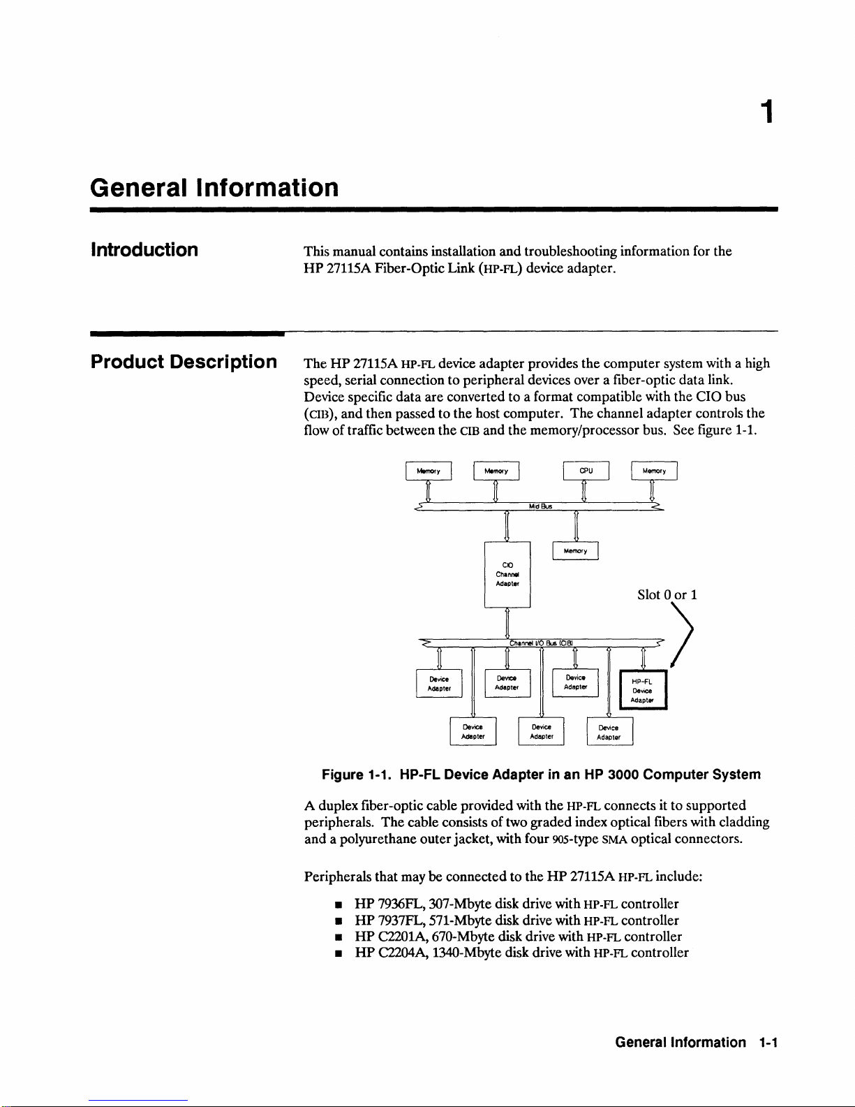
27115A HP-FL device adapter provides the computer system with a high
speed, serial connection to peripheral devices over a fiber-optic data link.
Device specific data are converted to a format compatible with the CIO bus
(cm), and then passed to the host computer. The channel adapter controls the
flow
of
traffic between the cm and the memory/processor bus. See figure 1-1.
Channel
Adapter
Figure 1-1. HP-FL Device Adapter
A duplex fiber-optic cable provided with the HP-FL connects
peripherals.
and a polyurethane outer jacket, with four 90s-type SMA optical connectors.
Peripherals that may
•
•
•
•
The
cable consists of two graded index optical fibers with cladding
be
connected to the
HP
7936FL, 307-Mbyte disk drive with HP-FL controller
HP
7937FL, 571-Mbyte disk drive with HP-FL controller
HP
C2201A, 670-Mbyte disk drive with HP-FL controller
HP
C2204A, 134O-Mbyte disk drive with HP-FL controller
in
an HP 3000 Computer System
it
to supported
HP
27115A HP-FL include:
Generallnformation
1-1

Features
Table 1-1 summarizes key features
of
this product.
Disk clusters
I/O slot efficiency
Transfer
Omoading
rates
the
and
host
CPU
Optical fiber cable
Table 1-1. Summary
HP-FL
can connect the host with up to 8 disk drives in a cluster. This can result in a large
number
required. The drives use a
fiber link.
The
HP-FL
the channel,
The
operations and data transfers with minimal host intervention. It also conducts a hardware
self-test,
Fiber-optic cable is thin, lightweight and flexible. It is not susceptible to electronic or
magnetic noise and provides electrical isolation The cable may be up to 500 meters long,
allowing greater flexibility in locating disk drives.
Tools", to
of
disk drives attached to your system while lowering the number
"daisy-chain" connection called the "PBus" to move data to the
HP-FL
protocol can transfer
device
adapter
and
HP-FL
on-board microprocessor controls the
and
displays results
order
is less than 1 ms. (Additional overhead accrues from the software,
the disk controller.)
a cable other than 30 m long.)
up
to 5 Mbytes
of
internal and external link status checks by means of 6
of
HP
27115A Features
of
I/O slots
per
second.
HP-FL
(See "Cables, Test Equipment, and
The
overhead imposed by the
protocol. It manages
PCA
LEOs.
Equipment
Supplied
The following items are provided with the standard
• 27115-60001
• 1005-0078 30
• 5061-3151 PBus terminator (quantity = 2)
• 27115-90001
HP-FL
device adapter
m,
duplex fiber-optic cable with
HP
27115A Fiber-Optic
Figure 1-2.
HP
27115A Fiber Optic Link
PCA
Link
HP
27115A product:
90s-type
Installation Manual
SMA
connectors
1-2 Generallnformation
Options
Depending
#001
available separately from Hewlett-Packard.
#002
If
any
hardware,
on
the
Deletes
Adds
item
the
a 3O-cm, single-fiber
is missing
contact
options
standard
or
incorrect,
your
nearest
below,
the
above items
3O-meter HP-FL cable.
loopback
or
you
would
HP
Sales
and
cable,
like
Support
may
Cables
part
to
have
been
in
number
order
Office.
modified:
special lengths
HFBR-3020.
additional
are
Cables, Test
Equipment and
Tools
Note
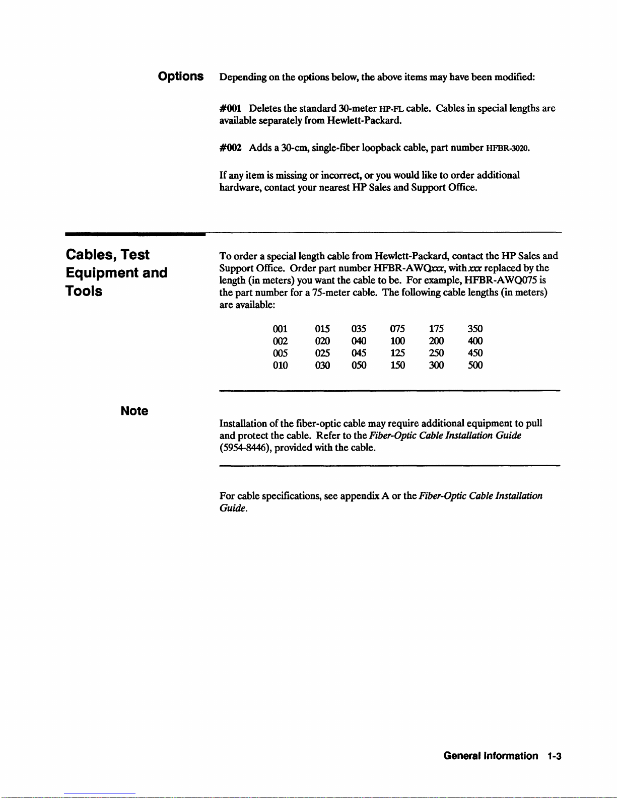
To
order
a special length
Support
length
the
are
Installation
and
(5954-8446),
For
Office.
(in
meters)
part
number
available:
protect
cable
specifications,
Guide.
cable
Order
part
you want
for a 75-meter cable.
001
002
005
010
of
the
the
provided
015
020
025
030
fiber-optic cable may
cable.
Refer
with
see
from
Hewlett-Packard,
number
the
HFBR-AWOnx,
cable
to
The
035
040
045
050
to
the
Fiber-Optic
the
cable.
appendix A or
be.
For
following
075
100
125
150
require
the
contact
withxa
example,
cable
175
200
250
300
additional
Cable
Installation Guide
Fiber-Optic
the
HP
replaced
HFBR-A
lengths
(in
350
400
450
500
equipment
Cable
Installation
Sales
by
the
WQ075 is
meters)
to
pull
and
General Information
1-3
Test
Equipment
Test
equipment
after
installation.
connectors
•
Optical
•
Optical
•
905/906
Refer
to
your supplier's catalog for various
A
single-fiber
subsystem components.
single-fiber cable for this
HFBR-3020).
loopback testing
27115ApCA.
may
be
This
on
the
cable ends.
power
meter,
power
source,
series
SMA
loopback
Alternatively,
if
cable
both
equipment
required
Option
purpose
ends
to
test
the
fiber-optic cable,
must
be
able
to
connect
The
following
for example,
for example,
adapter,
allows convenient troubleshooting
for example,
#002
(this cable is available as
one
of
the
fibers
of
the
fiber
equipment
Photodyne
Photodyne
Photodyne
to
options
the
on
are
and
product
a duplex
available for connection
both
before
with
the
90S-type SMA
can
be
used:
ModeluXE*
ModeI8XE-B*
Model
accessories available.
provides a short,
part
cable
of
number
can
2003*
HP-FL
be
used
to
and
for
the
HP
Note
Tools
Installation
adjustment
the
ferrule
screwdriver.
strain-relief ferrule.
The
decision
a
replacement
with
for details.
A fiber-optic tool kit
tools
replenishment kit,
used
(HP
the
and
in
part
the
or
routing
of
a strain-relief ferrule
to
the
cable,
See
figure 2-5
to
repair
cable.
required
minor
number
repair
tools
parts
part
process. )
HFBR-400(1)
the
cable may
and
will
and
a fiber-optic cable
The
repair
and
parts.
(Amphenol
for making
number
You
require
on
require
the
accompanying text for details
will
Test
part
these
927-100-2039t,
must also have two, 90S-type SMA
to
make
assembly, disassembly,
the
fiber-optic cable.
the
use
of
depends
take a trained
the
cable after
number
repairs.
the
927-100-S9OSt)
(Amphenol
with
replacements
repair
Two
screws
a O-point Pozidriv
about
on
the
availability
technician
the
about
repair.
See
is available
also offers a
for those
connectors
or
or
Phillips
the
and
two
chapter
that
secure
cost
hours
has
parts
of
3
1-4
General
Information
* Available from:
Photodyne Inc.
3760 Calle
Camarillo, California, U.S.A. 93010
t Available from:
Amphenol
1938C University
Lisle, Illinois, U.S.A. 60532
Tecate
Fiber
Optics
Lane
Installation Desig n
This section describes supported computer-to-disk connections.
Note
Caution
or
Connecting two
Although the hardware connection is possible, software for multiple computer
disk sharing is not available.
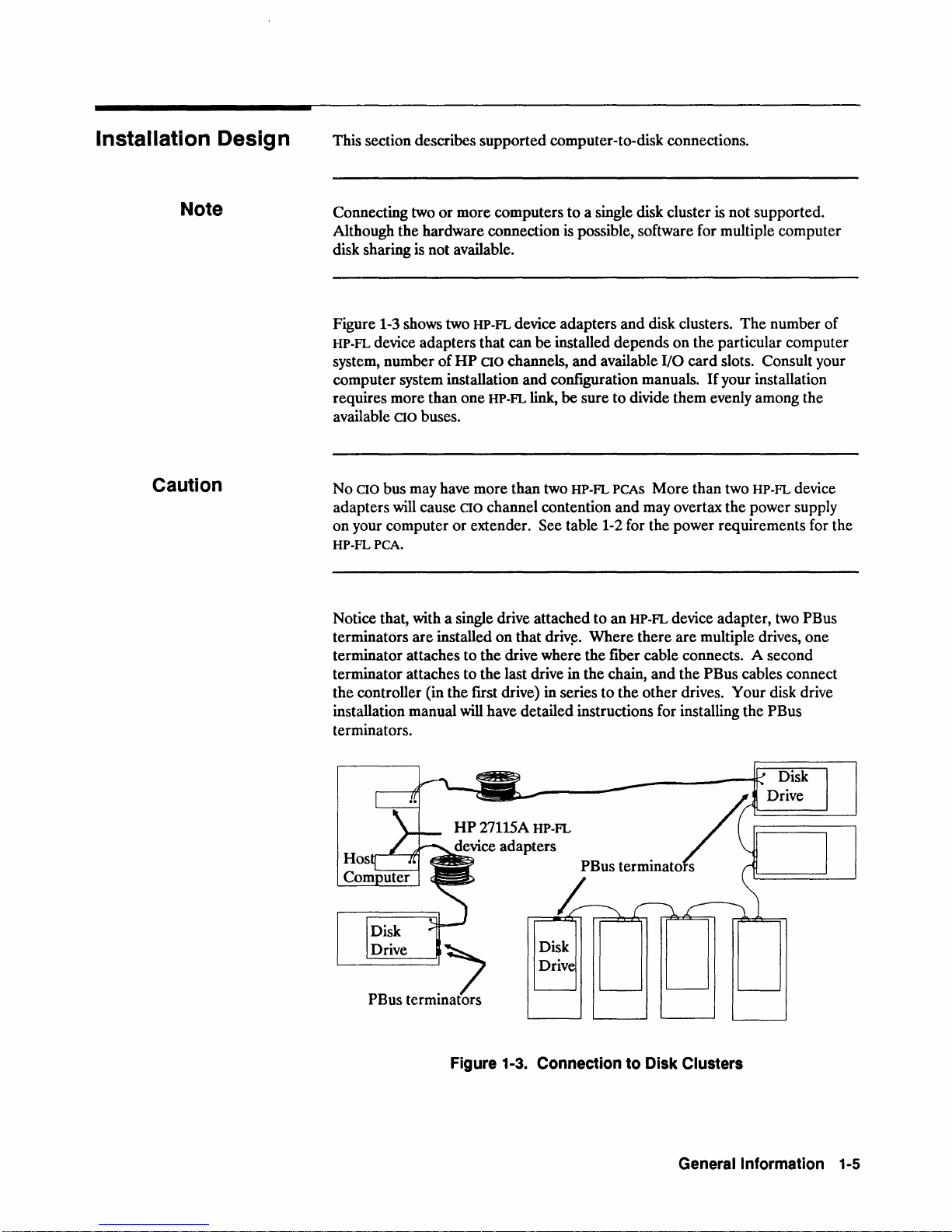
Figure 1-3 shows two
HP-FL device adapters that can
system, number
computer system installation
requires more than one HP-FL
available
No
adapters will cause
on
HP-FLPCA.
Notice that, with a single drive attached to
terminators
terminator attaches to the drive where the fiber cable connects.
terminator attaches
the controller (in the first drive) in series to the
installation manual will have detailed instructions for installing the PBus
terminators.
CIO buses.
CIO bus may have more than two HP-FL PCAS
your computer
more computers to a single disk cluster is not supported.
HP-FL device adapters and disk clusters.
be
are
installed depends
of
HP
CIO channels,
and
CIO
channel contention and may overtax the power supply
or
extender. See table 1-2 for the power requirements for the
installed
on
that
to
the last drive in the chain,
and
available
configuration manuals.
link,
be sure to divide them evenly among the
an
driv~.
Where
on
the particular computer
I/O
card
slots. Consult your
If
your installation
More
than two HP-FL device
HP-FL device adapter, two PBus
there
are
multiple drives, one
and
the PBus cables connect
other
drives. Your disk drive
The
number of
A second
PBus
terminL
Figure
Disk
Driv
1-3.
Connection to Disk Clusters
Generallnformation
1-5
HP-FL Subsystem
Considerations
There
are
various subsystem considerations associated with installing the
PCA
that will affect system operation
and
performance.
HP-FL
Number of Disk Drives
CIO
Slots
Note
Channel Contention
The
HP-FL
software
HP-FL
PCA.
However, your computer
or
fewer. See your system manuals for details.
The
total number
the computer,
extenders. Depending
CIO
slots. However, you must install the
14
lowest-numbered slots in any given
Install the
As
noted
multiple
CIO
HP-FL
HP-FL
above, some systems have more
CIO
buses to minimize channel contention problems.
PCAs
and
can
control as many as eight disk drives through a single
or
installation may limit this number to six
of
CIO
slots available for general device
and
whether it supports additional CIB channel
on
the system, each channel
CIB.
PCA
in
one
of
the
slots
numbered
than
buses
and
two
more than
CIO
buses,
put
one
one
HP-FL
PCA
adapter
HP-FL
PCA
from 0 to 7 in any
one
CIB.
PCA,
divide the
on
each bus.
adapters
adapters
supports from 5 to
in
one
of
the eight
With a host with
PCAS
For
instance, with two
depends on
or
CIO
bus.
among the
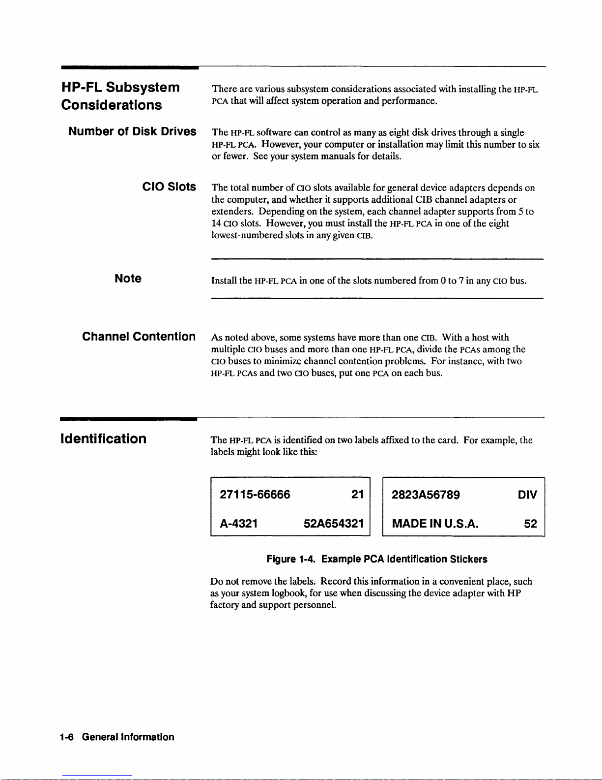
Identification
The
HP-FL
PCA
is identified
labels might look like this:
27115-66666
A-4321 52A654321
Figure 1-4. Example
Do
not remove the labels.
as your system logbook, for use when discussing
factory
and
support personnel.
on
two labels affixed
21
peA
Record
this information in a convenient place, such
2823A56789
MADE IN U.S.A.
Identification Stickers
to
the card.
the
device
For
adapter
example, the
DIV
52
with
HP
1-6 Generallnformation
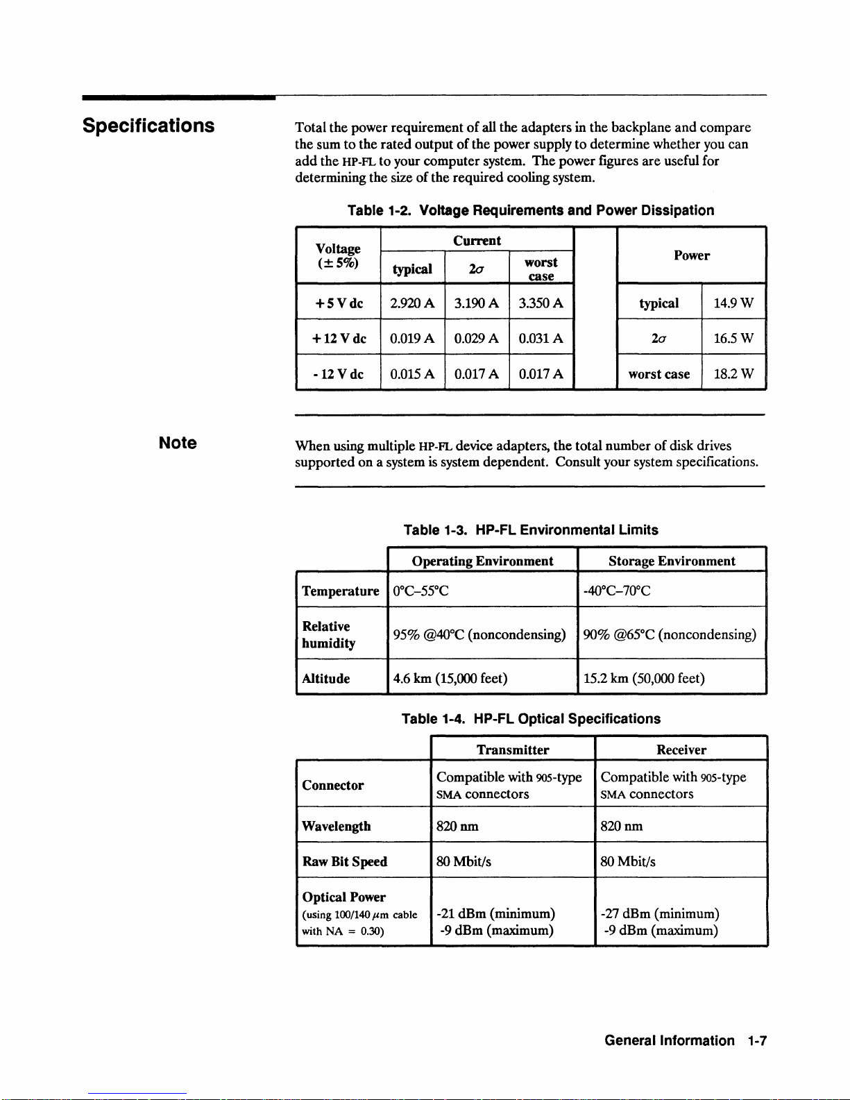
Specifications
Total the power requirement
the sum
add
determining the size
to
the
the HP-FL
rated
output
to
your computer system.
of
the required cooling system.
Table 1-2. Voltage Requirements and Power Dissipation
of
all the adapters in the backplane
of
the power supply
The
to
determine whether you can
power figures
are
useful for
and
compare
Note
Voltage
(±S%)
+SVdc
+12
V dc 0.019 A 0.029 A 0.031 A
-12
V dc
typical 20
2.920 A 3.190 A 3.350 A
0.015 A 0.017 A 0.017 A worst case
When using multiple HP-FL device adapters, the total number
Current
worst
case
typical
20
of
disk drives
Power
14.9W
16.5W
18.2W
supported on a system is system dependent. Consult your system specifications.
Table 1-3. HP-FL Environmental Limits
Operating Environment Storage Environment
Temperature
Relative
humidity
0°C-5SOC
95% @40°C (noncondensing) 90% @65°C (noncondensing)
-40°C-70°C
Altitude 4.6 km (15,000 feet)
Table 1-4. HP-FL Optical Specifications
Transmitter
Connector
Wavelength
Raw Bit Speed
Compatible with 90s-type Compatible with 90s-type
SMA connectors SMA connectors
820nm
80 Mbit/s 80 Mbit/s
Optical Power
(using
100/140
with NA =
I'm
0.30)
cable
-21 dBm (minimum) -27 dBm (minimum)
-9 dBm (maximum) -9 dBm (maximum)
15.2 km (50,000 feet)
Receiver
820nm
Generallnformation
1-7


Installation and Configuration
2
HP-FL Installation
Caution
Installation
1.
2.
3. Install
4.
5. Verify
The
HP
susceptible
static-free work area.
These
ESD
can
can
void your warranty.
If
you
the
one
conductive work
Instructions for its use
of
the
HP
27115A
Configure
Verify the position
Connect the fiber-optic cable.
27115A Fiber-Optic Link
to
•
Handle
• Avoid working
•
Reduce
precautions will lessen the chances
damage any electronic assembly. Failure to follow anti-ESD precautions
do
not have a static-free work area, we
provided as
the
link into
the
Hp·FL
peA.
the
link operation.
damage by electrostatic discharge (ESD).
the
peA
by its edges
on a carpet
unnecessary movements.
part
number
mat
and
other
come
Hp·FL
device
the
operating system.
of
jumper
(HP.FL)
or
9300-1155.
items
with the kit.
adapter
J2.
printed
extractor levers
of
ESD
to
safely shunt any charge
takes five steps:
circuit assembly
If
damage.
recommend
It
has a grounding wrist strap, a
(peA)
is
possible, work in a
a workstation kit, like
to
ground.
Installation
and
Configuration 2-1
Configure the Link
into the Operating
System
To
configure the HP-FL PCA and peripheral drives into the operating system,
refer to your system administrator's manuals and the disk drive manuals. You
may configure the operating system either before
hardware.
or
after installation of the
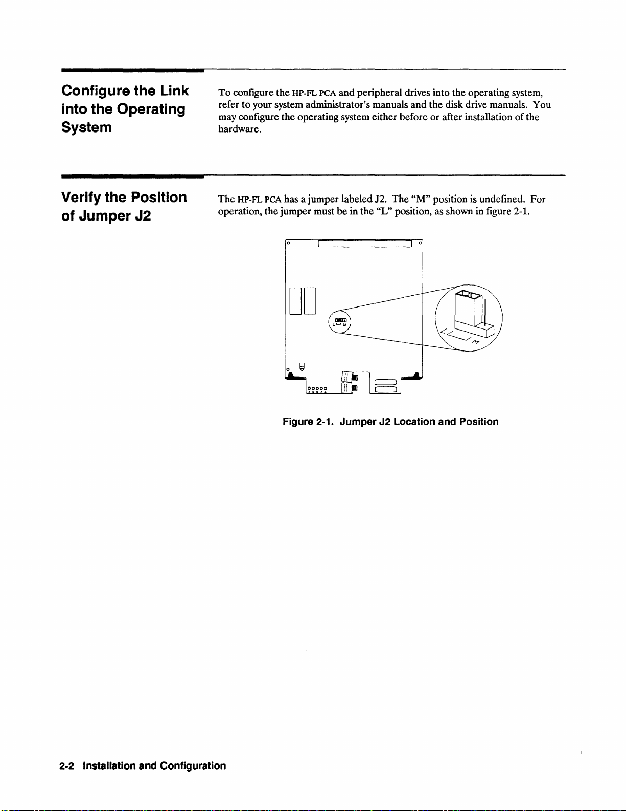
Verify
the Position
of Jumper J2
The
HP-FL PCA has a jumper labeled J2.
operation, the jumper must
o
be
DD
Figure 2·1. Jumper J2 Location and Position
The
"M"
position
in the "L" position, as shown in figure 2-1.
is
undefined. For
2·2 Installation and Configuration
Install the HP-FL
peA
Slot selection depends
titled
"HP-FL
administrator's manual will identify those slots where the
Subsystem Considerations" in chapter
on
how your system is configured. Review the section
1.
Your system
HP-FL PCA
is
allowed.
WARNING
Switch
Before
procedures
Failure
and
The
extender unit. Because this operation is system dependent, refer to the system
hardware manuals supplied with your computer for details. You will:
off
the
computer
switching
off
explained
to
follow
in
data
HP-FL PCA must
1.
Shut down the operating system.
2.
Switch off the computer power.
3.
Open
4.
Insert the PCA into a CIO
the
connector in the
into the backplane connector. Leave about 5 cm (2 in.) protruding to
allow installation
loss
the CIO
peA
the
or
correctly,
power
the
power,
in
your
correct
when
carefully
system
procedure
corruption.
be
installed into the CIO
card
cage.
card
and
seating the PCA connector onto the backplane
CIO bus. However,
of
the fiber-optic cable.
installing
follow
or
removing
the
shutdown
a peA.
manuals.
may
result
in
electrical
card
cage
of
your computer
cage slot. This step includes orienting
do
not insert the
PCA
shock
or
completely
Installation
and
Configuration
2-3
 Loading...