

Page 1

HP 2533t Mobile Thin Client
Maintenance and Service Guide
Page 2

© Copyright 2008 Hewlett-Packard
Development Company, L.P.
Bluetooth is a trademark owned by its
proprietor and used by Hewlett-Packard
Company under license. Microsoft,
Windows, and Windows Vista are U.S.
registered trademarks of Microsoft
Corporation. SD Logo is a trademark of its
proprietor.
The information contained herein is subject
to change without notice. The only
warranties for HP products and services are
set forth in the express warranty statements
accompanying such products and services.
Nothing herein should be construed as
constituting an additional warranty. HP shall
not be liable for technical or editorial errors
or omissions contained herein.
First Edition: May 2008
Document Part Number: 462925-001
Page 3

Safety warning notice
WARNING! To reduce the possibility of heat-related injuries or of overheating the computer, do not
place the computer directly on your lap or obstruct the computer air vents. Use the computer only on a
hard, flat surface. Do not allow another hard surface, such as an adjoining optional printer, or a soft
surface, such as pillows or rugs or clothing, to block airflow. Also, do not allow the AC adapter to contact
the skin or a soft surface, such as pillows or rugs or clothing, during operation. The computer and the
AC adapter comply with the user-accessible surface temperature limits defined by the International
Standard for Safety of Information Technology Equipment (IEC 60950).
iii
Page 4

iv Safety warning notice
Page 5

Table of contents
1 Product description
2 External component identification
Top components ................................................................................................................................... 4
Display ................................................................................................................................. 4
TouchPad ............................................................................................................................ 5
Buttons ................................................................................................................................. 6
Keys ..................................................................................................................................... 7
Lights ................................................................................................................................... 8
Front components .............................................................................................................................. 10
Right-side components ....................................................................................................................... 11
Left-side components ......................................................................................................................... 12
Rear components ............................................................................................................................... 13
Bottom components ........................................................................................................................... 14
3 Illustrated parts catalog
Serial number location ........................................................................................................................ 15
Computer major components ............................................................................................................. 16
Plastics Kit .......................................................................................................................................... 19
Cable Kit ............................................................................................................................................. 20
Miscellaneous parts ............................................................................................................................ 20
Sequential part number listing ............................................................................................................ 21
4 Removal and replacement procedures
Preliminary replacement requirements ............................................................................................... 23
Tools required .................................................................................................................... 23
Service considerations ....................................................................................................... 23
Plastic parts ....................................................................................................... 23
Cables and connectors ..................................................................................... 24
Drive handling ................................................................................................... 24
Grounding guidelines ......................................................................................................... 25
Electrostatic discharge damage ........................................................................ 25
Packaging and transporting guidelines ............................................. 26
v
Page 6

Workstation guidelines ..................................................................... 26
Equipment guidelines ....................................................................... 27
Unknown user password ................................................................................................... 28
Component replacement procedures ................................................................................................. 29
Serial number .................................................................................................................... 29
Computer feet .................................................................................................................... 30
Battery ............................................................................................................................... 30
Memory module ................................................................................................................. 32
WLAN module .................................................................................................................... 34
Flash drive ......................................................................................................................... 36
Optical drive ....................................................................................................................... 38
Switch cover and keyboard ................................................................................................ 40
USB board and optical drive bezel .................................................................................... 44
RTC battery ....................................................................................................................... 46
Display assembly ............................................................................................................... 47
Top cover ........................................................................................................................... 52
LED board .......................................................................................................................... 55
Speaker ............................................................................................................................. 56
System board ..................................................................................................................... 57
PC Card assembly ............................................................................................................. 59
Modem module .................................................................................................................. 61
Heat sink ............................................................................................................................ 63
5 Computer Setup
Starting Computer Setup .................................................................................................................... 65
Using Computer Setup ....................................................................................................................... 66
Computer Setup menus ..................................................................................................................... 67
6 Specifications
Computer specifications ..................................................................................................................... 69
12.1-inch, WXGA display specifications ............................................................................................. 70
8X Max DVD-ROM Drive specifications ............................................................................................. 71
System DMA specifications ................................................................................................................ 72
System interrupt specifications ........................................................................................................... 73
System I/O address specifications ..................................................................................................... 74
System memory map specifications ................................................................................................... 76
Navigating and selecting in Computer Setup ..................................................................... 66
Restoring factory settings in Computer Setup ................................................................... 66
File menu ........................................................................................................................... 67
Security menu .................................................................................................................... 67
Diagnostics menu .............................................................................................................. 67
System Configuration menu .............................................................................................. 68
vi
Page 7

7 Screw listing
Phillips PM2.5×6.0 captive screw ....................................................................................................... 78
Phillips PM2.0×4.0 screw ................................................................................................................... 79
Torx T8M2.0×5.0 screw ..................................................................................................................... 82
Torx T8M2.5×6.0 screw ..................................................................................................................... 84
Phillips PM2.5×11.0 captive screw ..................................................................................................... 87
Phillips PM2.5×4.0 screw ................................................................................................................... 88
Phillips PM2.0×6.0 screw ................................................................................................................... 89
Phillips PM2.0×5.0 screw ................................................................................................................... 90
Torx T8M2.0×10.0 captive screw ....................................................................................................... 91
8 Connector pin assignments
Audio-out (headphone) ....................................................................................................................... 92
Audio-in (microphone) ........................................................................................................................ 92
External monitor ................................................................................................................................. 93
RJ-11 (modem) .................................................................................................................................. 94
RJ-45 (network) .................................................................................................................................. 95
Universal Serial Bus ........................................................................................................................... 95
9 Power cord set requirements
Requirements for all countries and regions ........................................................................................ 96
Requirements for specific countries and regions ............................................................................... 97
10 Recycling
Battery ................................................................................................................................................ 98
Display ................................................................................................................................................ 98
Index ................................................................................................................................................................. 104
vii
Page 8

viii
Page 9

1 Product description
Category Description
Product Name HP 2533t Mobile Thin Client
Processors Via C7-M Ultra-Low Voltage (ULV) 1.00-GHz, 128-KB L2 cache, 400-MHz front side bus (FSB)
Chipset Northbridge: Via CN896
Southbridge: Via VT8237S
Graphics Via Chrome 9 Universal Memory Architecture (UMA) graphics subsystem integrated with 128-MB
shared system memory
Panels 12.1-inch WXGA display assembly (1280 × 800) with Antiglare, includes 2 wireless local area
network (WLAN) antennae, and supports privacy filter
Memory One customer-accessible/upgradable memory module slot
Supports up to 2 GB of system RAM
PC2-5300, 667-MHz, DDR2
Supports the following configurations:
2048-MB total system memory (2048 × 1)
●
1024-MB total system memory (1024 × 1)
●
Primary storage device 1-GB flash drive
Customer-accessible
Parallel ATA (PATA)
Optical drives Fixed (removal of 2 screws required)
Customer-accessible
Serial ATA (SATA)
9.5-mm tray load
Supports the following drive options:
DVD-ROM Drive
●
No optical drive with optical drive space saver
●
Diskette drive Supports external USB diskette drive only
Supports boot from external USB diskette drive
Supports 3-mode diskette drive
1
Page 10

Category Description
Audio HD audio - ADI1984HDA
Integrated single speaker, no speaker branding
Integrated single microphone
Modem 56K V.92 1.5-inch data/fax modem
Ethernet Integrated Broadcom 5787M 10/100/1000 (local access network (LAN)
S5 wake on LAN on AC power
NIC power down technology
Wireless Integrated WLAN options by way of wireless module:
Support for 2 dual-band 2.4-/5.0-GHz WLAN antennae built into display assembly
Support for no-WLAN option
Support for Broadcom 802.11a/b/g WLAN format
External media card One Type I/II PC Card slot, 16-bit PCMCIA and 32-bit Cardbus
SD/MMC Card Reader supporting Secure Digital (SD) Memory Card and MultiMediaCard (MMC)
Ports Audio-in (stereo microphone)
Audio-out (stereo headphone)
Docking
RJ-11 (modem)
RJ-45 (Ethernet, includes link and activity lights)
USB (2 with optical drive, 3 without optical drive)
VGA (Dsub 15-pin) supporting 1600 × 1200 external resolution at 75-GHz (hot plug/unplug with
3-pin AC power via the HP Smart Adapter
Docking HP 2400/2500 Series Docking Station (TV-out connector does not work)
Keyboard/pointing
devices
Pointing stick with 2 pointing stick buttons
TouchPad with 2 TouchPad buttons and vertical scrolling zone
Spill-resistant keyboard
Windows Vista® Start button
Durable key caps
Power requirements 65-W AC adapter with localized cable plug support (2-wire plug with ground pin, supports 3-pin DC
9-cell, 83.0-Wh Li-ion battery with fuel gauge
auto-detect)
4.21-inch × 10.71-inch keyboard with embedded numeric keypad
connector)
6-cell, 55.0-Wh Li-ion battery with fuel gauge
3-cell, 31.0-Wh Li-ion battery with fuel gauge
2 Chapter 1 Product description
Page 11

Category Description
Security Supports Kensington security sock
Optional removable active smart card reader, occupies the single PC Card slot
Operating system Preinstalled:
Windows® XP Embedded (XPe) in French, Japanese, Korean, Simplified Chinese, Spanish,
Traditional Chinese, and U.S. English
Serviceability End-user replaceable parts:
AC adapter
Battery (system)
Flash drive
Memory module
Optical drive
RTC battery
WLAN module
3
Page 12

2 External component identification
Top components
Display
Item Component Function
(1) Wireless antennae (2) Send and receive signals from one or more wireless
(2) Internal microphone Records sound.
4 Chapter 2 External component identification
devices. These antennae are not visible from the outside
of the computer.
NOTE: For optimal transmission, keep the areas
immediately around the antennae free from
obstructions.
NOTE: To see wireless regulatory notices, refer to the
section of the Regulatory, Safety and Environmental
Notices that applies to your country or region. These
notices are located in the printed Getting Started
guide.
Page 13

TouchPad
Item Component Function
(1) Pointing stick* Moves the pointer and selects or activates items on
the screen.
(2) Left pointing stick button* Functions like the left button on an external mouse.
(3) TouchPad* Moves the pointer and selects or activates items on
the screen.
(4) Left TouchPad button* Functions like the left button on an external mouse.
(5) Right pointing stick button* Functions like the right button on an external mouse.
(6) TouchPad scroll zone Scrolls up or down.
(7) Right TouchPad button* Functions like the right button on an external mouse.
*This table describes factory settings. To view or change pointing device preferences, select Start > Control Panel > Printers
and Other Hardware > Mouse.
Top components 5
Page 14

Buttons
Item Component Function
(1) Power button
(2) Info button Launches Info Center.
(3) Wireless button Turns the wireless feature on or off, but does not
(4) Presentation button Opens the Presentation Options window, where you can
(5) TouchPad on/off button Turns the TouchPad on or off.
(6) Volume mute button Mutes and restores computer sound.
(7) Volume scroll zone Adjusts speaker volume. Slide your finger to the left to
When the computer is off, press the button to turn
●
on the computer.
When the computer is on, press the button to turn
●
off the computer.
When the computer is in Standby, press the button
●
briefly to exit Standby.
establish a wireless connection.
NOTE: A wireless network must be set up in order to
establish a wireless connection.
start a frequently used presentation, file, program, or
Web site. You can also adjust display settings for
optimum viewing.
decrease volume and to the right to increase volume.
6 Chapter 2 External component identification
Page 15

Keys
Item Component Function
(1) esc key Displays system information when pressed in
combination with the fn key.
(2) fn key Executes frequently used system functions when
pressed in combination with a function key or the esc
key.
(3) Windows logo key Displays the Windows Start menu.
(4) Windows applications key Displays a shortcut menu for items beneath the pointer.
(5) Embedded numeric keypad keys Can be used like the keys on an external numeric
keypad.
(6) Function keys Execute frequently used system functions when
pressed in combination with the fn key.
Top components 7
Page 16

Lights
Item Component Function
(1) Wireless lights* (2)
(2) Power lights† (2)
(3) Battery light
(4) Drive light Blinking: The flash drive or optional optical drive is
(5) TouchPad on/off light
Blue: An integrated wireless device, such as a
●
wireless local area network (WLAN) device, is on.
Amber: All wireless devices are off.
●
On: The computer is on.
●
Blinking: The computer is in Standby.
●
Off: The computer is off.
●
Amber: A battery is charging.
●
Turquoise: A battery is close to full charge capacity.
●
Blinking amber: A battery that is the only available
●
power source has reached a low battery level.
When the battery reaches a critical battery level,
the battery light begins blinking rapidly.
Off: If the computer is plugged into an external
●
power source, the light turns off when all batteries
in the computer are fully charged. If the computer
is not plugged into an external power source, the
light stays off until the battery reaches a low battery
level.
being accessed.
Turquoise: TouchPad is on.
●
(6) Caps lock light On: Caps lock is on.
(7) Num lock light On: Num lock is on.
8 Chapter 2 External component identification
Amber: TouchPad is off.
●
Page 17

Item Component Function
(8) Volume mute light
*The 2 wireless lights display the same information. The light on the wireless button is visible only when the computer is open.
The wireless light on the front of the computer is visible whether the computer is open or closed.
†The 2 power lights display the same information. The light on the power button is visible only when the computer is open. The
power light on the front of the computer is visible whether the computer is open or closed.
Turquoise: Computer sound is on.
●
Amber: Computer sound is off.
●
Top components 9
Page 18

Front components
Item Component Function
(1) Wireless light
(2) Power light
(3) Battery light
(4) Drive light Blinking: The flash drive or optional optical drive is
(5) Display release latch Opens the computer.
Blue: An integrated wireless device, such as a
●
wireless local area network (WLAN) device, is on.
Amber: All wireless devices are off.
●
On: The computer is on.
●
Blinking: The computer is in Standby.
●
Off: The computer is off.
●
Amber: A battery is charging.
●
Turquoise: A battery is close to full charge capacity.
●
Blinking amber: A battery that is the only available
●
power source has reached a low battery level.
When the battery reaches a critical battery level,
the battery light begins blinking rapidly.
Off: If the computer is plugged into an external
●
power source, the light turns off when all batteries
in the computer are fully charged. If the computer
is not plugged into an external power source, the
light stays off until the battery reaches a low battery
level.
being accessed.
10 Chapter 2 External component identification
Page 19

Right-side components
Item Component Function
(1) PC Card slot* Supports optional Type I and Type II 32-bit (CardBus) or
(2) SD Card Reader* Supports the Secure Digital (SD) Memory Card and
(3) Audio-out (headphone) jack Produces sound when connected to optional powered
(4) Audio-in (microphone) jack Connects an optional computer headset microphone,
(5) USB port† Connects an optional USB device.
(6) External monitor port Connects an external VGA monitor or projector.
16-bit PC Cards.
MultiMediaCard (MMC) optional digital card formats.
stereo speakers, headphones, ear buds, a headset, or
television audio.
stereo array microphone, or monaural microphone.
(7) Vent Enables airflow to cool internal components.
(8) Docking connector Connects an optional docking device.
*To view the status of the PC Card Slot and SD Card Reader, go to Computer Setup (f10).
†To view the status of the USB ports, use the USB Storage Options utility. Refer to the “Securing USB ports” section in the
Administrator's Guide for additional information.
Right-side components 11
Page 20

Left-side components
NOTE: Refer to the illustration that most closely matches your computer.
Item Component Function
(1) Power connector Connects an AC adapter.
(2) RJ-11 (modem) jack Connects a modem cable.
(3) Powered USB port* Provides power to an external device if used with a
(4) Vent Enables airflow to cool internal components.
(5) USB port* Connects an optional USB device.
*To view the status of the USB ports, use the USB Storage Options utility. Refer to the “Securing USB ports” section in the
Administrator's Guide for additional information.
powered USB cable.
Item Component Function
(1) Power connector Connects an AC adapter.
(2) RJ-11 (modem) jack Connects a modem cable.
(3) Powered USB port* Provides power to an external device if used with a
(4) Vent Enables airflow to cool internal components.
(5) Optical drive (select models only) Reads an optical disc.
*To view the status of the USB ports, use the USB Storage Options utility. Refer to the “Securing USB ports” section in the
Administrator's Guide for additional information.
12 Chapter 2 External component identification
powered USB cable.
Page 21

Rear components
Item Component Function
(1) RJ-45 (network) jack Connects a network cable.
(2) Security cable slot Attaches an optional security cable to the computer.
NOTE: The security cable is designed to act as a
deterrent, but it may not prevent the computer from
being mishandled or stolen.
Rear components 13
Page 22

Bottom components
Item Component Function
(1) Speaker Produces sound.
(2) Memory module compartment Contains a memory module slot and a WLAN
module slot.
CAUTION: To prevent an unresponsive system,
replace the wireless module only with a wireless module
authorized for use in the computer by the governmental
agency that regulates wireless devices in your country
or region. If you replace the module and then receive a
warning message, remove the module to restore
computer functionality.
(3) Vents (5) Enable airflow to cool internal components.
(4) Battery release latches (2) Release the battery from the battery bay.
(5) Battery bay Holds the battery.
(6) Flash drive bay Holds the flash drive.
14 Chapter 2 External component identification
Page 23

3 Illustrated parts catalog
Serial number location
When ordering parts or requesting information, provide the computer serial number and model number
located on the bottom of the computer.
Serial number location 15
Page 24

Computer major components
Item Description Spare part number
(1) 12.1-inch, WXGA AntiGlare display assembly (includes display panel cable, 2 WLAN
antenna transceivers and cables, and microphones)
Display assembly subcomponents (not illustrated):
16 Chapter 3 Illustrated parts catalog
481103-001
Page 25

Item Description Spare part number
Display bezel (includes HP logo and computer model number label) 481097-001
Display bezel adhesive 497013-001
Display panel cable 481099-001
Display enclosure (includes HP logo, wireless antenna transceivers and cables, and
microphone receiver and cable)
Display Hinge Kit (includes left and right hinges and brackets) 481098-001
(2) Switch cover (includes display lid switch board and cable) 481093-001
(3) Keyboards with pointing stick (include keyboard cable and pointing stick cable)
For use in French Canada 481112-121
For use in Japan 481112-291
For use in Latin America 481112-161
For use in South Korea 481112-AD1
For use in Taiwan 481112-AB1
For use in the United States 481112-001
(4) RTC battery 481089-001
(5) Top cover (includes TouchPad board and cable, TouchPad button board and cable, and
(6) PC Card assembly 481104-001
Plastics Kit (see Plastics Kit on page 19 for more Plastics Kit spare part information): 481105-001
For use in Brazil 481112-201
TouchPad bracket)
481100-001
481111-001
(7a) PC Card slot bezel
(7b) Bluetooth® module compartment cover
(7c) Flash drive compartment cover
(7d) Memory module compartment cover
(7e) Rear cover
(8)
(9) Modem modules
For use only in Australia and New Zealand 461750-002
(10) Heat sink (includes replacement thermal material and replacement thermal material
(11) Batteries
9-cell, 83.0-WH Li-ion
System board (includes processor, replacement thermal material, and replacement thermal
material cleaning kit)
NOTE: The modem module spare part kits do not include a modem module cable. The modem module cable is
included in the Cable Kit, spare part number 481092-001. See
number information.
For use in all countries and regions except Australia and New Zealand 461750-001
cleaning kit)
Cable Kit on page 20 for more Cable Kit spare part
481091-001
481110-001
481088-001
Computer major components 17
Page 26

Item Description Spare part number
6-cell, 55.0-WH Li-ion 481087-001
3-cell, 31.0-WH Li-ion 481086-001
(12) LED board (includes cable and Mylar cover) 481090-001
(13) Speaker 481109-001
(14) DVD-ROM Drive (includes bezel and bracket) 481094-001
(15) USB board (includes optical drive bezel and USB board cable) 481102-001
(16) Base enclosure (includes display latch switch, battery release latch, and rubber feet) 481085-001
Rubber Kit (not illustrated, contains 4 computer feet, 4 display bezel screw covers, and
business card holder)
(17) Solid-state, parallel ATA (PATA) flash drives (include flash drive bracket)
1-GB solid-state, PATA flash drive 481095-001
(18) Broadcom 802.11a/b/g WLAN modules:
2-GB solid-state, PATA flash drive 494352-001
For use in Canada, the Cayman Islands, Guam, Puerto Rico, the U.S. Virgin Islands,
●
and the United States
For use in Afghanistan, Albania, Algeria, Andorra, Angola, Antigua and Barbuda,
●
Argentina, Armenia, Aruba, Australia, Austria, Azerbaijan, the Bahamas, Bahrain,
Bangladesh, Barbados, Belarus, Belgium, Belize, Benin, Bermuda, Bhutan, Bolivia,
Bosnia and Herzegovina, Botswana, Brazil, the British Virgin Islands, Brunei, Bulgaria,
Burkina Faso, Burundi, Cameroon, Cape Verde, the Central African Republic, Chad,
Chile, the People's Republic of China, Colombia, Comoros, the Congo, Costa Rica,
Croatia, Cyprus, the Czech Republic, Denmark, Djibouti, Dominica,
the Dominican Republic, East Timor, Ecuador, Egypt, El Salvador, Equatorial Guinea,
Eritrea, Estonia, Ethiopia, Fiji, Finland, France, French Guiana, Gabon, Gambia,
Georgia, Germany, Ghana, Gibraltar, Greece, Grenada, Guadeloupe, Guatemala,
Guinea, Bissau, Guyana, Haiti, Honduras, Hong Kong, Hungary, Iceland, India, Ireland,
Israel, Italy, the Ivory Coast, Jamaica, Jordan, Kazakhstan, Kenya, Kiribati, Kyrgyzstan,
Laos, Latvia, Lebanon, Lesotho, Liberia, Liechtenstein, Lithuania, Luxembourg,
Macedonia, Madagascar, Malawi, Malaysia, the Maldives, Mali, Malta,
the Marshall Islands, Martinique, Mauritania, Mauritius, Mexico, Micronesia, Monaco,
Mongolia, Montenegro, Morocco, Mozambique, Namibia, Nauru, Nepal,
the Nether Antilles, the Netherlands, New Zealand, Nicaragua, Niger, Nigeria, Norway,
Oman, Pakistan, Palau, Panama, Papua New Guinea, Paraguay, Peru, the Philippines,
Poland, Portugal, the Republic of Moldova, Romania, Russia, Rwanda, Samoa,
San Marino, Sao Tome and Principe, Saudi Arabia, Senegal, Serbia, the Seychelles,
Sierra Leone, Singapore, Slovakia, Slovenia, the Solomon Islands, Somalia,
South Africa, South Korea, Spain, Sri Lanka, St. Kitts and St. Nevis, St. Lucia,
St. Vincent and the Grenadines, Suriname, Swaziland, Sweden, Switzerland, Taiwan,
Tajikistan, Tanzania, Togo, Tonga, Trinidad and Tobago, Tunisia, Turkey,
Turkmenistan, Tuvalu, Uganda, Ukraine, the United Arab Emirates, the United Kingdom,
Uruguay, Uzbekistan, Vanuatu, Venezuela, Vietnam, Yemen, Zaire, Zambia,
and Zimbabwe
481106-001
441075-001
441075-002
(19) 1024-MB memory module (PC2-5300, 667-MHz, DDR2) 481101-001
Smart card reader (not illustrated) 481108-001
Cable Kit (not illustrated; see Cable Kit on page 20 for more Cable Kit spare part
For use in Japan
●
number information)
18 Chapter 3 Illustrated parts catalog
441075-291
480092-001
Page 27

Plastics Kit
Item Description Spare part number
Plastics Kit: 481105-001
(1) PC Card slot bezel
(2) Flash drive compartment cover (includes 2 captive screws, secured by C-clips)
(3)
Bluetooth module compartment cover (includes one captive screw, secured by a C-clip)
(4) Memory module compartment cover (includes one captive screw, secured by a C-clip)
(5) Rear cover (includes 2 captive screws, secured by C-clips)
Plastics Kit 19
Page 28

Cable Kit
Item Description Spare part number
Cable Kit: 481092-001
(1) Wireless antenna transceivers and cables
(2) Microphone receiver and cable
(3) LED board cable
(4) Modem module cable
Miscellaneous parts
Description Spare part number
65-W, 3-prong, PFC AC adapter 463958-001
Power cord 490371-001
Screw Kit
Phillips PM2.5×11.0 captive screw
●
Phillips PM2.5×6.0 captive screw
●
Phillips PM2.5×4.0 screw
●
Phillips PM2.0×6.0 screw
●
Phillips PM2.0×5.0 screw
●
Phillips PM2.0×4.0 screw
●
Torx T8M2.5×10.0 captive screw
●
Torx T8M2.5×6.0 screw
●
481107-001
Torx T8M2.0×5.0 screw
●
20 Chapter 3 Illustrated parts catalog
Page 29

Sequential part number listing
Spare part
number
441075-001 Broadcom 802.11a/b/g WLAN module for use in Canada, the Cayman Islands, Guam, Puerto Rico,
441075-002 Broadcom 802.11a/b/g WLAN module for use in Afghanistan, Albania, Algeria, Andorra, Angola,
441075-291 Broadcom 802.11a/b/g WLAN module for use in Japan
Description
the U.S. Virgin Islands, and the United States
Antigua and Barbuda, Argentina, Armenia, Aruba, Australia, Austria, Azerbaijan, the Bahamas, Bahrain,
Bangladesh, Barbados, Belarus, Belgium, Belize, Benin, Bermuda, Bhutan, Bolivia, Bosnia and Herzegovina,
Botswana, Brazil, the British Virgin Islands, Brunei, Bulgaria, Burkina Faso, Burundi, Cameroon, Cape Verde,
the Central African Republic, Chad, Chile, the People's Republic of China, Colombia, Comoros, the Congo,
Costa Rica, Croatia, Cyprus, the Czech Republic, Denmark, Djibouti, Dominica, the Dominican Republic,
East Timor, Ecuador, Egypt, El Salvador, Equatorial Guinea, Eritrea, Estonia, Ethiopia, Fiji, Finland, France,
French Guiana, Gabon, Gambia, Georgia, Germany, Ghana, Gibraltar, Greece, Grenada, Guadeloupe,
Guatemala, Guinea, Bissau, Guyana, Haiti, Honduras, Hong Kong, Hungary, Iceland, India, Ireland, Israel,
Italy, the Ivory Coast, Jamaica, Jordan, Kazakhstan, Kenya, Kiribati, Kyrgyzstan, Laos, Latvia, Lebanon,
Lesotho, Liberia, Liechtenstein, Lithuania, Luxembourg, Macedonia, Madagascar, Malawi, Malaysia,
the Maldives, Mali, Malta, the Marshall Islands, Martinique, Mauritania, Mauritius, Mexico, Micronesia,
Monaco, Mongolia, Montenegro, Morocco, Mozambique, Namibia, Nauru, Nepal, the Nether Antilles,
the Netherlands, New Zealand, Nicaragua, Niger, Nigeria, Norway, Oman, Pakistan, Palau, Panama,
Papua New Guinea, Paraguay, Peru, the Philippines, Poland, Portugal, the Republic of Moldova, Romania,
Russia, Rwanda, Samoa, San Marino, Sao Tome and Principe, Saudi Arabia, Senegal, Serbia, the Seychelles,
Sierra Leone, Singapore, Slovakia, Slovenia, the Solomon Islands, Somalia, South Africa, South Korea, Spain,
Sri Lanka, St. Kitts and St. Nevis, St. Lucia, St. Vincent and the Grenadines, Suriname, Swaziland, Sweden,
Switzerland, Taiwan, Tajikistan, Tanzania, Togo, Tonga, Trinidad and Tobago, Tunisia, Turkey, Turkmenistan,
Tuvalu, Uganda, Ukraine, the United Arab Emirates, the United Kingdom, Uruguay, Uzbekistan, Vanuatu,
Venezuela, Vietnam, Yemen, Zaire, Zambia, and Zimbabwe
461750-001 Modem module for use in all countries and regions except Australia and New Zealand
NOTE: The modem module spare part kits do not include a modem module cable. The modem module cable
is included in the Cable Kit, spare part number 481092-001. See
part number information.
461750-002 Modem module for use only in Australia and New Zealand
NOTE: The modem module spare part kits do not include a modem module cable. The modem module cable
is included in the Cable Kit, spare part number 481092-001. See
part number information.
463958-001 65-W, 3-prong, PFC AC adapter
481085-001 Base enclosure (includes display latch switch, battery release latch, and rubber feet)
481086-001 3-cell, 31.0-WH, Li-ion battery
481087-001 6-cell, 55.0-WH, Li-ion battery
481088-001 9-cell, 83.0-WH, Li-ion battery
481089-001 RTC battery
481090-001 LED board (includes cable and Mylar cover)
481091-001 System board (includes processor, replacement thermal material, and replacement thermal material
cleaning kit)
481092-001 Cable Kit (see Cable Kit on page 20 for more Cable Kit spare part number information)
Cable Kit on page 20 for more Cable Kit spare
Cable Kit on page 20 for more Cable Kit spare
481093-001 Switch cover (includes display lid switch board and cable)
481094-001 DVD-ROM Drive (includes bezel and bracket)
Sequential part number listing 21
Page 30

Spare part
number
481095-001 1-GB solid-state, PATA flash drive (includes flash drive bracket)
481097-001 Display bezel (includes HP logo and model number label)
481098-001 Display hinges (includes left and right hinges and brackets)
481099-001 Display panel cable
481100-001 Display enclosure (includes wireless antenna transceivers and cables and microphone receiver and cable)
481101-001 1024-MB memory module (PC2-5300, 667-MHz, DDR2)
481102-001 USB board (includes optical drive bezel and USB board cable)
481103-001 12.1-inch, WXGA AntiGlare display assembly (includes 2 WLAN antenna transceivers and cables
481104-001 PC Card assembly
481105-001 Plastics Kit (see Plastics Kit on page 19 for more Plastics Kit spare part information):
481106-001 Rubber Kit (contains 4 computer feet, 4 display bezel screw covers, and business card holder)
481107-001 Screw Kit
481108-001 Smart card reader
481109-001 Speaker
Description
and microphones)
481110-001 Heat sink (includes replacement thermal material and replacement thermal material cleaning kit)
481111-001 Top cover (includes TouchPad board and cable, TouchPad button board and cable, and TouchPad bracket)
481112-001 Keyboard with pointing stick for use in the United States (includes keyboard cable and pointing stick cable)
481112-121 Keyboard with pointing stick for use in French Canada (includes keyboard cable and pointing stick cable)
481112-161 Keyboard with pointing stick for use in Latin America (includes keyboard cable and pointing stick cable)
481112-201 Keyboard with pointing stick for use in Brazil (includes keyboard cable and pointing stick cable)
481112-291 Keyboard with pointing stick for use in Japan (includes keyboard cable and pointing stick cable)
481112-AB1 Keyboard with pointing stick for use in Taiwan (includes keyboard cable and pointing stick cable)
481112-AD1 Keyboard with pointing stick for use in South Korea (includes keyboard cable and pointing stick cable)
490371-001 Power cord
494352-001 2-GB solid-state, PATA flash drive (includes flash drive bracket)
497013-001 Display bezel adhesive
22 Chapter 3 Illustrated parts catalog
Page 31

4 Removal and replacement procedures
Preliminary replacement requirements
Tools required
You will need the following tools to complete the removal and replacement procedures:
Flat-bladed screwdriver
●
Magnetic screwdriver
●
Phillips P0 and P1 screwdrivers
●
Torx T8 screwdriver
●
Service considerations
The following sections include some of the considerations that you must keep in mind during
disassembly and assembly procedures.
NOTE: As you remove each subassembly from the computer, place the subassembly (and all
accompanying screws) away from the work area to prevent damage.
Plastic parts
Using excessive force during disassembly and reassembly can damage plastic parts. Use care when
handling the plastic parts. Apply pressure only at the points designated in the maintenance instructions.
Preliminary replacement requirements 23
Page 32

Cables and connectors
CAUTION: When servicing the computer, be sure that cables are placed in their proper locations
during the reassembly process. Improper cable placement can damage the computer.
Cables must be handled with extreme care to avoid damage. Apply only the tension required to unseat
or seat the cables during removal and insertion. Handle cables by the connector whenever possible. In
all cases, avoid bending, twisting, or tearing cables. Be sure that cables are routed in such a way that
they cannot be caught or snagged by parts being removed or replaced. Handle flex cables with extreme
care; these cables tear easily.
Drive handling
CAUTION: Drives are fragile components that must be handled with care. To prevent damage to the
computer, damage to a drive, or loss of information, observe these precautions:
Before removing or inserting a flash drive, shut down the computer.
Before handling a drive, be sure that you are discharged of static electricity. While handling a drive,
avoid touching the connector.
Before removing a diskette drive or optical drive, be sure that a diskette or disc is not in the drive and
be sure that the optical drive tray is closed.
Handle drives on surfaces covered with at least one inch of shock-proof foam.
Avoid dropping drives from any height onto any surface.
After removing a flash drive, an optical drive, or a diskette drive, place it in a static-proof bag.
Avoid exposing a flash drive to products that have magnetic fields, such as monitors or speakers.
Avoid exposing a drive to temperature extremes or liquids.
If a drive must be mailed, place the drive in a bubble pack mailer or other suitable form of protective
packaging and label the package “FRAGILE.”
24 Chapter 4 Removal and replacement procedures
Page 33

Grounding guidelines
Electrostatic discharge damage
Electronic components are sensitive to electrostatic discharge (ESD). Circuitry design and structure
determine the degree of sensitivity. Networks built into many integrated circuits provide some protection,
but in many cases, ESD contains enough power to alter device parameters or melt silicon junctions.
A discharge of static electricity from a finger or other conductor can destroy static-sensitive devices or
microcircuitry. Even if the spark is neither felt nor heard, damage may have occurred.
An electronic device exposed to ESD may not be affected at all and can work perfectly throughout a
normal cycle. Or the device may function normally for a while, then degrade in the internal layers,
reducing its life expectancy.
CAUTION: To prevent damage to the computer when you are removing or installing internal
components, observe these precautions:
Keep components in their electrostatic-safe containers until you are ready to install them.
Before touching an electronic component, discharge static electricity by using the guidelines described
in this section.
Avoid touching pins, leads, and circuitry. Handle electronic components as little as possible.
If you remove a component, place it in an electrostatic-safe container.
The following table shows how humidity affects the electrostatic voltage levels generated by different
activities.
CAUTION: A product can be degraded by as little as 700 V.
Typical electrostatic voltage levels
Relative humidity
Event 10% 40% 55%
Walking across carpet 35,000 V 15,000 V 7,500 V
Walking across vinyl floor 12,000 V 5,000 V 3,000 V
Motions of bench worker 6,000 V 800 V 400 V
Removing DIPS from plastic tube 2,000 V 700 V 400 V
Removing DIPS from vinyl tray 11,500 V 4,000 V 2,000 V
Removing DIPS from Styrofoam 14,500 V 5,000 V 3,500 V
Removing bubble pack from PCB 26,500 V 20,000 V 7,000 V
Packing PCBs in foam-lined box 21,000 V 11,000 V 5,000 V
Preliminary replacement requirements 25
Page 34

Packaging and transporting guidelines
Follow these grounding guidelines when packaging and transporting equipment:
To avoid hand contact, transport products in static-safe tubes, bags, or boxes.
●
Protect ESD-sensitive parts and assemblies with conductive or approved containers or packaging.
●
Keep ESD-sensitive parts in their containers until the parts arrive at static-free workstations.
●
Place items on a grounded surface before removing items from their containers.
●
Always be properly grounded when touching a component or assembly.
●
Store reusable ESD-sensitive parts from assemblies in protective packaging or nonconductive
●
foam.
Use transporters and conveyors made of antistatic belts and roller bushings. Be sure that
●
mechanized equipment used for moving materials is wired to ground and that proper materials are
selected to avoid static charging. When grounding is not possible, use an ionizer to dissipate
electric charges.
Workstation guidelines
Follow these grounding workstation guidelines:
Cover the workstation with approved static-shielding material.
●
Use a wrist strap connected to a properly grounded work surface and use properly grounded tools
●
and equipment.
Use conductive field service tools, such as cutters, screwdrivers, and vacuums.
●
When fixtures must directly contact dissipative surfaces, use fixtures made only of static-safe
●
materials.
Keep the work area free of nonconductive materials, such as ordinary plastic assembly aids and
●
Styrofoam.
Handle ESD-sensitive components, parts, and assemblies by the case or PCM laminate. Handle
●
these items only at static-free workstations.
Avoid contact with pins, leads, or circuitry.
●
Turn off power and input signals before inserting or removing connectors or test equipment.
●
26 Chapter 4 Removal and replacement procedures
Page 35

Equipment guidelines
Grounding equipment must include either a wrist strap or a foot strap at a grounded workstation.
When seated, wear a wrist strap connected to a grounded system. Wrist straps are flexible straps
●
with a minimum of one megohm ±10% resistance in the ground cords. To provide proper ground,
wear a strap snugly against the skin at all times. On grounded mats with banana-plug connectors,
use alligator clips to connect a wrist strap.
When standing, use foot straps and a grounded floor mat. Foot straps (heel, toe, or boot straps)
●
can be used at standing workstations and are compatible with most types of shoes or boots. On
conductive floors or dissipative floor mats, use foot straps on both feet with a minimum of one
megohm resistance between the operator and ground. To be effective, the conductive must be
worn in contact with the skin.
The following grounding equipment is recommended to prevent electrostatic damage:
Antistatic tape
●
Antistatic smocks, aprons, and sleeve protectors
●
Conductive bins and other assembly or soldering aids
●
Nonconductive foam
●
Conductive tabletop workstations with ground cords of one megohm resistance
●
Static-dissipative tables or floor mats with hard ties to the ground
●
Field service kits
●
Static awareness labels
●
Material-handling packages
●
Nonconductive plastic bags, tubes, or boxes
●
Metal tote boxes
●
Electrostatic voltage levels and protective materials
●
The following table lists the shielding protection provided by antistatic bags and floor mats.
Material Use Voltage protection level
Antistatic plastic Bags 1,500 V
Carbon-loaded plastic Floor mats 7,500 V
Metallized laminate Floor mats 5,000 V
Preliminary replacement requirements 27
Page 36

Unknown user password
If the computer you are servicing has an unknown user password, follow these steps to clear the
password:
NOTE: These steps also clear CMOS.
1. Shut down the computer.
2. Disconnect all external devices connected to the computer.
3. Disconnect the power from the computer by first unplugging the power cord from the AC outlet and
then unplugging the AC adapter from the computer.
4. Remove the battery (see
5. Remove the real-time clock (RTC) battery (see
6. Wait approximately 5 minutes.
7. Replace the RTC battery and reassemble the computer.
8. Connect AC power to the computer. Do not reinsert any batteries at this time.
9. Turn on the computer.
All passwords and all CMOS settings have been cleared.
Battery on page 30).
RTC battery on page 46).
28 Chapter 4 Removal and replacement procedures
Page 37

Component replacement procedures
This chapter provides removal and replacement procedures.
There are as many as 60 screws, in 9 different sizes, that must be removed, replaced, or loosened when
servicing the computer. Make special note of each screw size and location during removal and
replacement.
Serial number
Report the computer serial number to HP when requesting information or ordering spare parts. The
serial number is located on the bottom of the computer.
Component replacement procedures 29
Page 38
Computer feet
The computer feet are adhesive-backed rubber pads. The feet are included in the Rubber Kit, spare
part number 481106-001. There are 4 rubber feet that attach to the base enclosure in the locations
illustrated below.
Battery
Description Spare part number
9-cell, 83.0-WH, Li-ion battery 481088-001
6-cell, 55.0-WH, Li-ion battery 481087-001
3-cell, 31.0-WH, Li-ion battery 481086-001
Before disassembling the computer, follow these steps:
1. Shut down the computer.
2. Disconnect all external devices connected to the computer.
3. Disconnect the power from the computer by first unplugging the power cord from the AC outlet and
then unplugging the AC adapter from the computer.
Remove the battery:
1. Turn the computer upside down on a flat surface, with the battery bay toward you.
2. Slide the battery release latches (1) to release the battery.
30 Chapter 4 Removal and replacement procedures
Page 39
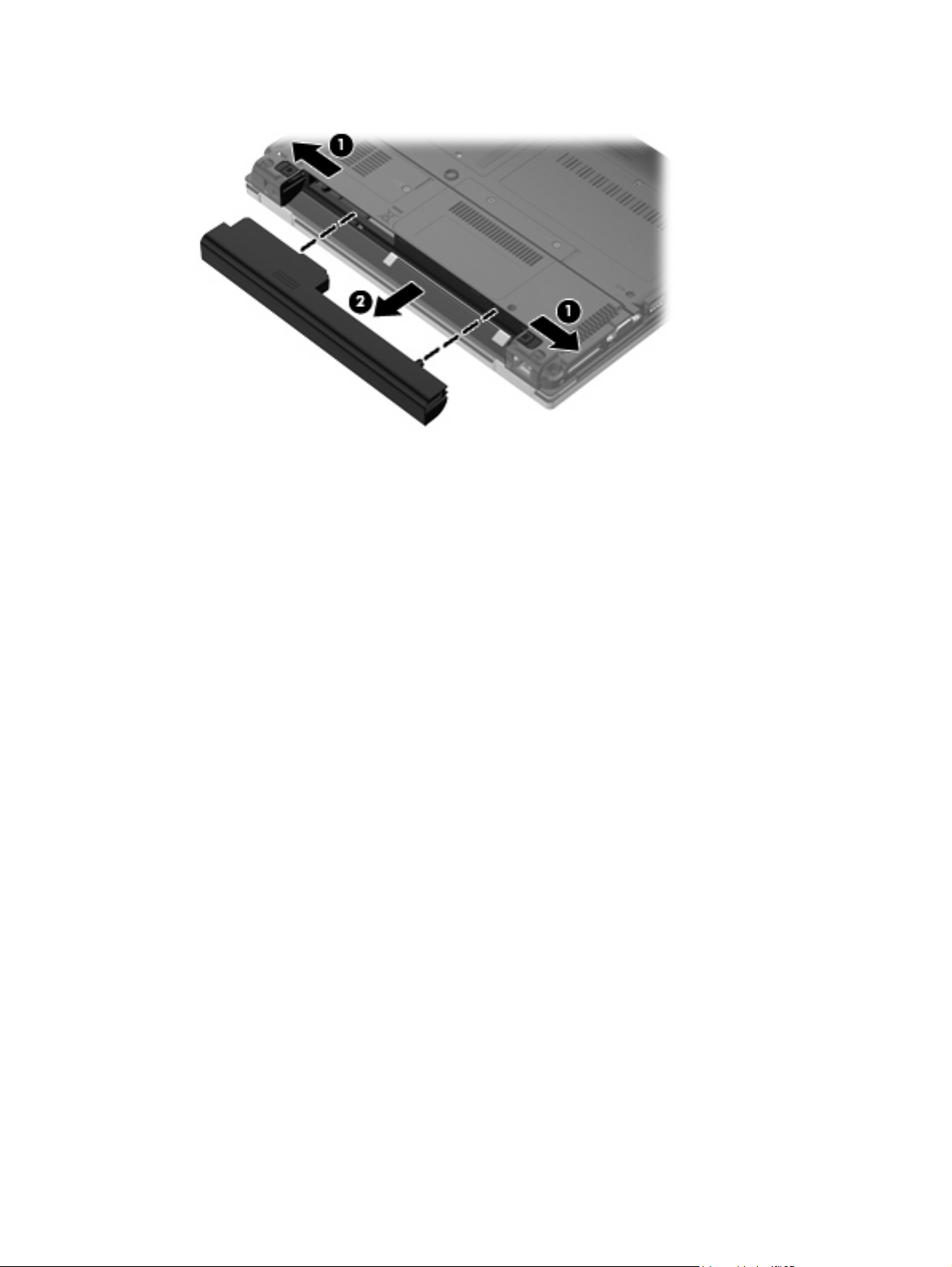
3. Remove the battery (2) from the computer.
Install the battery by inserting it into the battery bay until you hear a click.
Component replacement procedures 31
Page 40
Memory module
Description Spare part number
1024-MB (PC2-5300, 667-MHz, DDR2) 481101-001
Before removing the memory module, follow these steps:
1. Shut down the computer.
2. Disconnect all external devices connected to the computer.
3. Disconnect the power from the computer by first unplugging the power cord from the AC outlet and
then unplugging the AC adapter from the computer.
4. Remove the battery (see
Battery on page 30).
Remove the memory module:
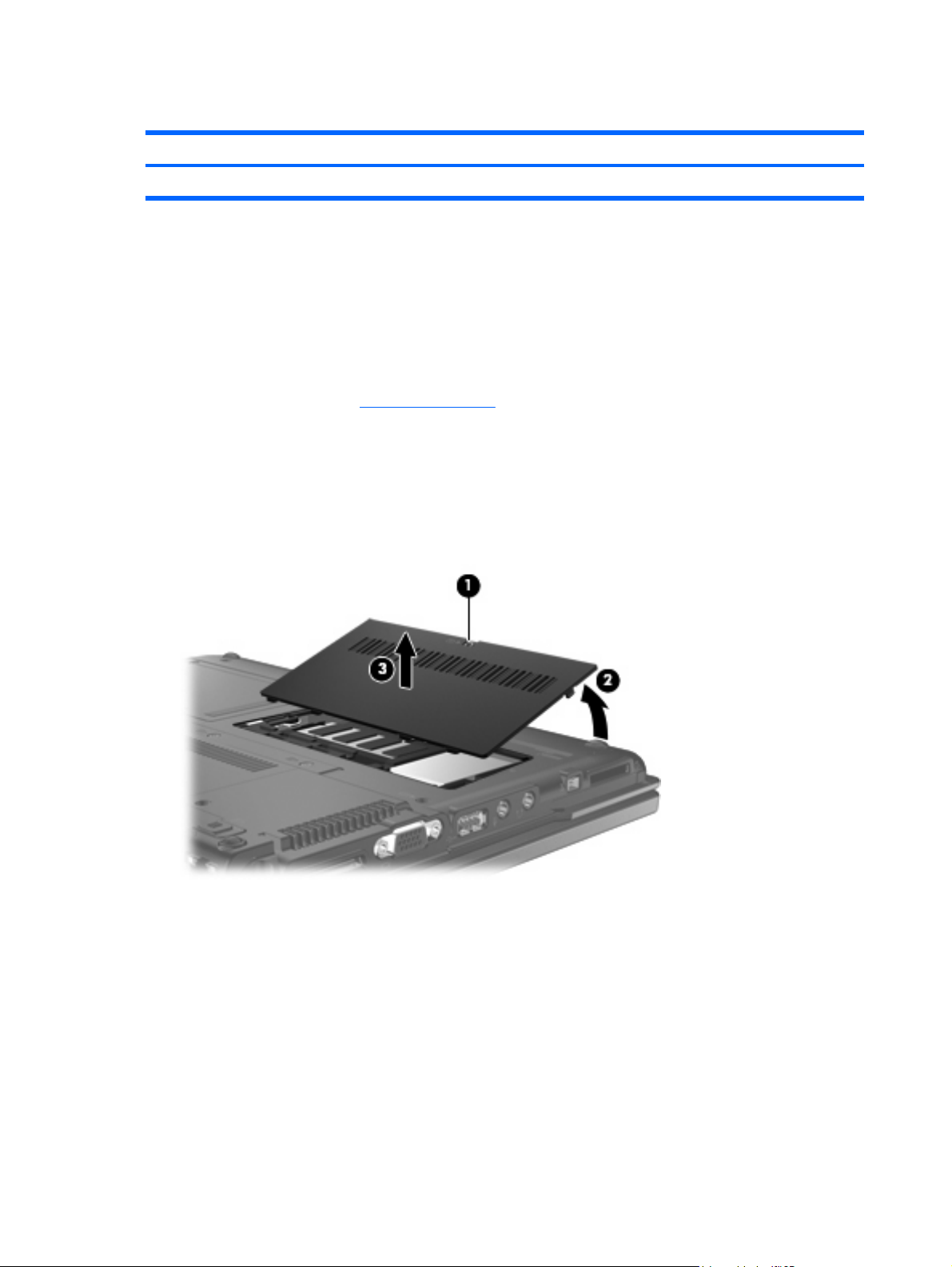
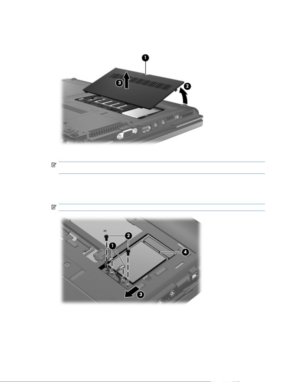
1. Loosen the Phillips PM2.5×6.0 captive screw (1) that secures the memory module compartment
cover to the computer.
2. Lift the front edge of the cover (2), swing it back, and remove the cover (3). The memory module
compartment cover is included in the Plastics Kit, spare part number 481105-001.
3. Spread the retaining tabs (1) on each side of the memory module slot to release the memory
module. (The edge of the module opposite the slot rises away from the computer.)
32 Chapter 4 Removal and replacement procedures
Page 41
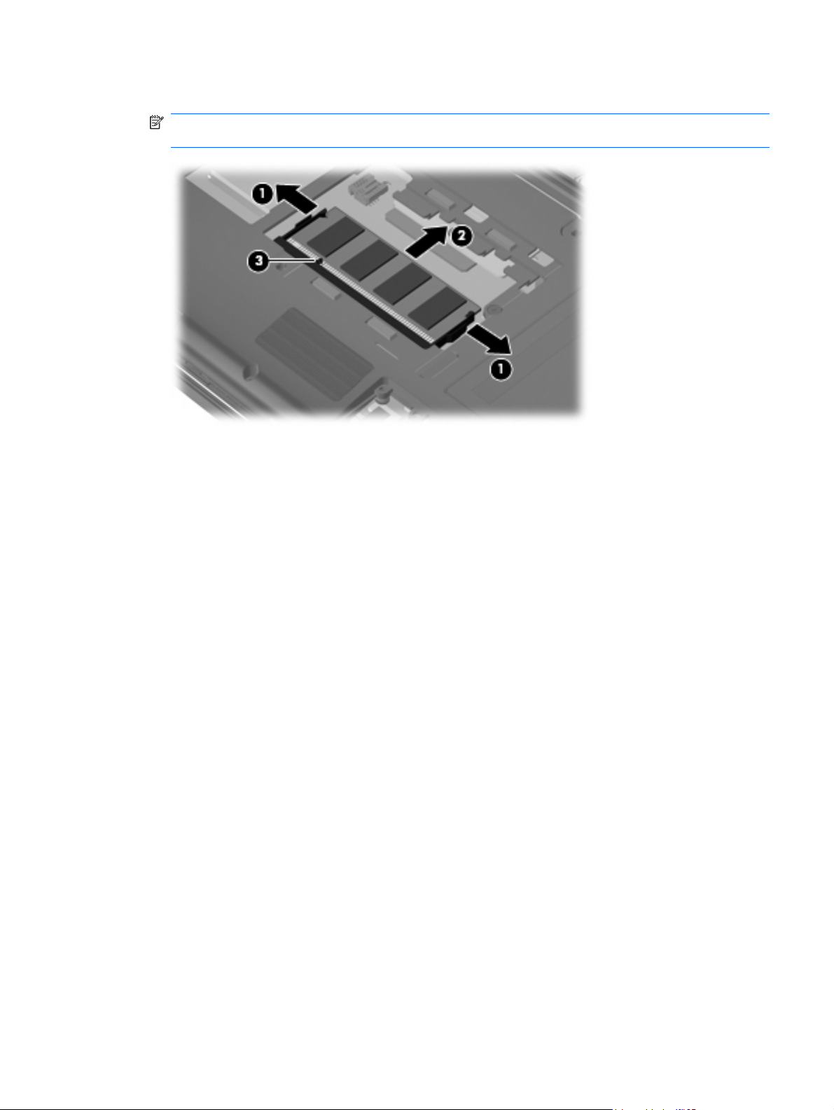
4. Remove the memory module (2) by pulling the module away from the slot at an angle.
NOTE: The memory module is designed with a notch (3) to prevent incorrect installation into the
memory module slot.
Reverse this procedure to install the memory module.
Component replacement procedures 33
Page 42

WLAN module
Description Spare part number
Broadcom 802.11a/b/g WLAN modules:
For use in Canada, the Cayman Islands, Guam, Puerto Rico, the U.S. Virgin Islands,
●
and the United States
For use in Afghanistan, Albania, Algeria, Andorra, Angola, Antigua and Barbuda, Argentina,
●
Armenia, Aruba, Australia, Austria, Azerbaijan, the Bahamas, Bahrain, Bangladesh,
Barbados, Belarus, Belgium, Belize, Benin, Bermuda, Bhutan, Bolivia,
Bosnia and Herzegovina, Botswana, Brazil, the British Virgin Islands, Brunei, Bulgaria,
Burkina Faso, Burundi, Cameroon, Cape Verde, the Central African Republic, Chad, Chile,
the People's Republic of China, Colombia, Comoros, the Congo, Costa Rica, Croatia,
Cyprus, the Czech Republic, Denmark, Djibouti, Dominica, the Dominican Republic,
East Timor, Ecuador, Egypt, El Salvador, Equatorial Guinea, Eritrea, Estonia, Ethiopia, Fiji,
Finland, France, French Guiana, Gabon, Gambia, Georgia, Germany, Ghana, Gibraltar,
Greece, Grenada, Guadeloupe, Guatemala, Guinea, Bissau, Guyana, Haiti, Honduras,
Hong Kong, Hungary, Iceland, India, Ireland, Israel, Italy, the Ivory Coast, Jamaica, Jordan,
Kazakhstan, Kenya, Kiribati, Kyrgyzstan, Laos, Latvia, Lebanon, Lesotho, Liberia,
Liechtenstein, Lithuania, Luxembourg, Macedonia, Madagascar, Malawi, Malaysia,
the Maldives, Mali, Malta, the Marshall Islands, Martinique, Mauritania, Mauritius, Mexico,
Micronesia, Monaco, Mongolia, Montenegro, Morocco, Mozambique, Namibia, Nauru,
Nepal, the Nether Antilles, the Netherlands, New Zealand, Nicaragua, Niger, Nigeria,
Norway, Oman, Pakistan, Palau, Panama, Papua New Guinea, Paraguay, Peru,
the Philippines, Poland, Portugal, the Republic of Moldova, Romania, Russia, Rwanda,
Samoa, San Marino, Sao Tome and Principe, Saudi Arabia, Senegal, Serbia, the Seychelles,
Sierra Leone, Singapore, Slovakia, Slovenia, the Solomon Islands, Somalia, South Africa,
South Korea, Spain, Sri Lanka, St. Kitts and St. Nevis, St. Lucia,
St. Vincent and the Grenadines, Suriname, Swaziland, Sweden, Switzerland, Taiwan,
Tajikistan, Tanzania, Togo, Tonga, Trinidad and Tobago, Tunisia, Turkey, Turkmenistan,
Tuvalu, Uganda, Ukraine, the United Arab Emirates, the United Kingdom, Uruguay,
Uzbekistan, Vanuatu, Venezuela, Vietnam, Yemen, Zaire, Zambia, and Zimbabwe
For use in Japan 441075-291
●
441075-001
441075-002
Before removing the WLAN module, follow these steps:
1. Shut down the computer.
2. Disconnect all external devices connected to the computer.
3. Disconnect the power from the computer by first unplugging the power cord from the AC outlet and
then unplugging the AC adapter from the computer.
4. Remove the battery (see
Battery on page 30).
Remove the WLAN module:
1. Loosen the Phillips PM2.5×6.0 captive screw (1) that secures the memory module compartment
cover to the computer.
34 Chapter 4 Removal and replacement procedures
Page 43
2. Lift the front edge of the memory module compartment cover (2), swing it back, and remove the
cover (3). The memory module compartment cover is included in the Plastics Kit, spare part number
481105-001.
3. Disconnect the WLAN antenna cables (1) from the terminals on the WLAN module.
NOTE: The black WLAN antenna cable is connected to the WLAN module “Main” terminal. The
white WLAN antenna cable is connected to the WLAN module “Aux” terminal.
4. Remove the two Phillips PM2.0×4.0 screws (2) that secure the WLAN module to the computer.
(The edge of the module opposite the slot rises away from the computer.)
5. Remove the WLAN module (3) by pulling the module away from the slot at an angle.
NOTE: WLAN modules are designed with a notch (4) to prevent incorrect installation.
Reverse this procedure to install the WLAN module.
Component replacement procedures 35
Page 44

Flash drive
NOTE: All flash drive spare part kits include a flash drive bracket).
Description Spare part number
2-GB solid-state, PATA flash drive 494352-001
1-GB solid-state, PATA flash drive 481095-001
Before removing the flash drive, follow these steps:
1. Shut down the computer.
2. Disconnect all external devices connected to the computer.
3. Disconnect the power from the computer by first unplugging the power cord from the AC outlet and
then unplugging the AC adapter from the computer.
4. Remove the battery (see
Battery on page 30).
Remove the flash drive:
1. Position the computer with the front toward you.
2. Loosen the Phillips PM2.5×6.0 captive screw (1) that secures the flash drive compartment cover
to the computer.
3. Lift the left side of the flash drive compartment cover (2), swing it to right, and remove the cover
(3). The flash drive compartment cover is included in the Plastics Kit, spare part number
481105-001.
CAUTION: The flash drive is connected to the system board by a delicate, multiple-pin connector.
The flash drive must be lifted straight up to be disconnected and removed. Any rocking motion
during removal can damage the flash drive pins on the system board.
36 Chapter 4 Removal and replacement procedures
Page 45

4. Lift the flash drive straight up to disconnect it from the system board (1).
NOTE: When installing the flash drive, be sure that the alignment pin on the system board is
aligned with the hole (2) on the flash drive.
Reverse this procedure to install the flash drive.
Component replacement procedures 37
Page 46

Optical drive
Description Spare part number
DVD-ROM Drive (includes bezel and bracket) 481094-001
Before removing the optical drive, follow these steps:
1. Shut down the computer.
2. Disconnect all external devices connected to the computer.
3. Disconnect the power from the computer by first unplugging the power cord from the AC outlet and
then unplugging the AC adapter from the computer.
4. Remove the battery (see
Battery on page 30).
Remove the optical drive:
1. Remove the memory module compartment cover (see
Memory module on page 32).
2. Position the computer with the right side toward you.
3. Remove the Mylar screw cover (1) that secures the optical drive retention screw. The Mylar screw
cover is available in the Rubber Kit, spare part number 481106-001.
4. Remove the two Torx T8M2.0×5.0 screws (2) that secure the optical drive to the computer.
5. Insert a thin tool, such as a paper clip (3), into the release access. (The optical drive disc tray is
partially ejected from the optical drive.)
6. Remove the optical drive (4) from the computer.
7. If it is necessary to replace the optical drive bracket, position the optical drive with the rear toward
you.
8. Remove the two Phillips PM2.0×4.0 screws (1) that secure the optical drive bracket to the optical
drive.
38 Chapter 4 Removal and replacement procedures
Page 47

9. Remove the optical drive bracket (2).
Reverse this procedure to reassemble and install an optical drive.
Component replacement procedures 39
Page 48
Switch cover and keyboard
Description Spare part number
Switch cover (includes display lid switch board and cable) 481093-001
Keyboards
For use in the following
countries or regions
Brazil 481112-201 South Korea 481112-AD1
French Canada 481112-121 Taiwan 481112-AB1
Japan 481112-291 The United States 481112-001
Latin America 481112-161
Spare part number For use in the following
countries or regions
Spare part number
Before removing the switch cover and keyboard, follow these steps:
1. Shut down the computer.
2. Disconnect all external devices connected to the computer.
3. Disconnect the power from the computer by first unplugging the power cord from the AC outlet and
then unplugging the AC adapter from the computer.
4. Remove the battery (see
Battery on page 30).
Remove the switch cover and keyboard:
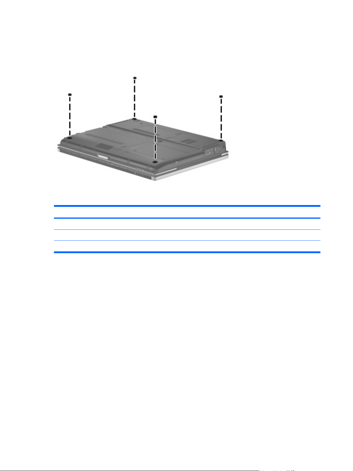
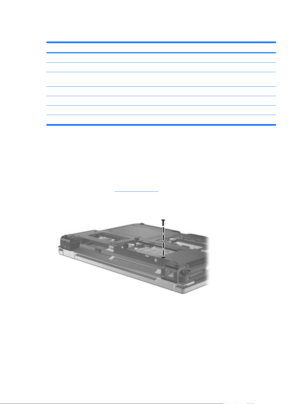
1. Remove the Torx8 T8M2.5×6.0 screw that secures the switch cover to the computer.
2. Loosen the two Phillips PM2.5×6.0 captive screws (1) that secure the rear cover to the computer.
40 Chapter 4 Removal and replacement procedures
Page 49
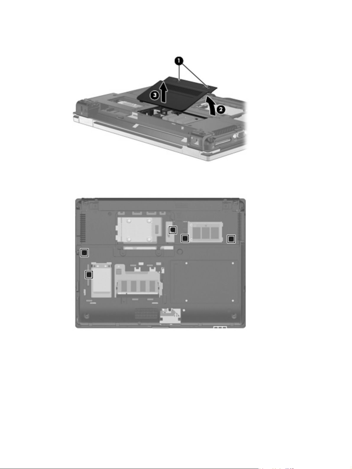
3. Lift the front edge of the rear cover (2), swing it back, and remove it (3). The rear cover is included
in the Plastics Kit, spare part number 481105-001.
4. Position the computer with the front toward you.
5. Loosen the five Phillips PM2.5×11.0 captive screws that secure the keyboard to the computer.
6. Turn the computer display-side up, with the front toward you.
7. Open the computer as far as possible.
8. Slide the switch cover to the right (1) to disengage it from the computer.
Component replacement procedures 41
Page 50
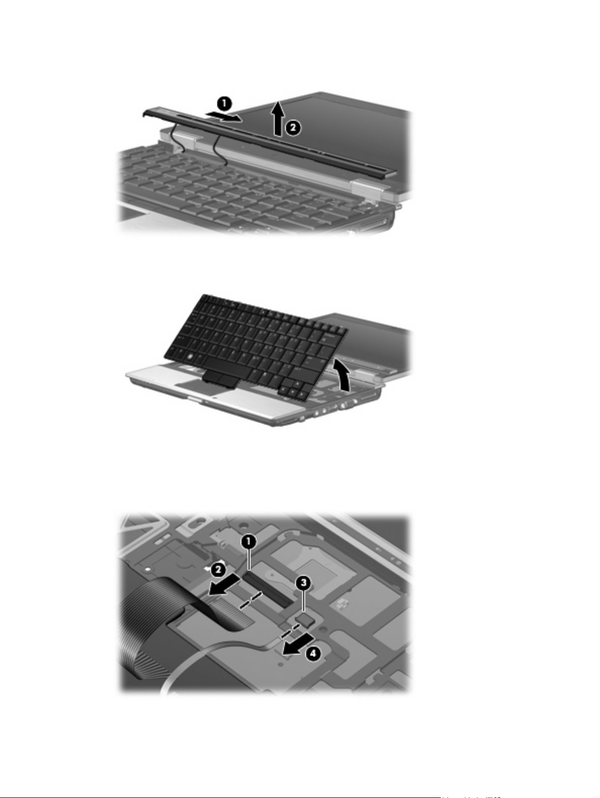
9. Lift the switch cover (2) as far as the two switch cover cables allow.
10. Lift the rear edge of the keyboard and swing it up and forward until it rests upside down on the palm
rest.
11. Release the zero insertion force (ZIF) connector (1) to which the keyboard cable is attached, and
disconnect the keyboard cable (2) from the system board.
12. Release the ZIF connector (3) to which the pointing stick cable is attached, and disconnect the
pointing stick cable (4) from the system board.
13. Remove the keyboard.
42 Chapter 4 Removal and replacement procedures
Page 51
14. Disconnect the display lid switch cable (1) and the LED board cable (2) from the system board.
15. Remove the switch cover (3).
Reverse this procedure to install the switch cover and keyboard.
Component replacement procedures 43
Page 52
USB board and optical drive bezel
Description Spare part number
USB board (includes optical drive bezel and cable) 481102-001
Before removing the USB board and optical drive bezel, follow these steps:
1. Shut down the computer.
2. Disconnect all external devices connected to the computer.
3. Disconnect the power from the computer by first unplugging the power cord from the AC outlet and
then unplugging the AC adapter from the computer.
4. Remove the battery (see
5. Remove the switch cover and keyboard (see
Battery on page 30).
Switch cover and keyboard on page 40).
Remove the USB board and optical drive bezel:
1. Turn the computer upside down, with the front toward you.
2. Remove the two Phillips PM2.0×4.0 screws that secure the optical drive bezel to the computer.
3. Turn the computer right-side up, with the front toward you.
4. Disconnect the USB board cable (1) from the system board.
44 Chapter 4 Removal and replacement procedures
Page 53

5. Release the optical drive bezel (2) by sliding it out of the base enclosure.
6. Remove the optical drive bezel from the optical drive bay.
7. Remove the two Phillips PM2.0×4.0 screws (1) that secure the USB board to the optical drive bezel.
8. Remove the USB board (2) from the optical drive bezel.
Component replacement procedures 45
Page 54

Reverse this procedure to install the USB board and optical drive bezel.
RTC battery
NOTE: Removing the RTC battery and leaving it uninstalled for 5 or more minutes causes all
passwords and CMOS settings to be cleared.
Description Spare part number
RTC battery 481089-001
Before removing the RTC battery, follow these steps:
1. Shut down the computer.
2. Disconnect all external devices connected to the computer.
3. Disconnect the power from the computer by first unplugging the power cord from the AC outlet and
then unplugging the AC adapter from the computer.
4. Remove the battery (see
5. Release the switch cover and keyboard (see
Battery on page 30).
Switch cover and keyboard on page 40).
Remove the RTC battery:
Remove the RTC battery from the socket on the system board.
Reverse this procedure to install the RTC battery.
46 Chapter 4 Removal and replacement procedures
Page 55
Display assembly
Description Spare part number
12.1-inch, WXGA AntiGlare display assembly (includes 2 WLAN antenna transceivers and cables
and microphones)
481103-001
Before removing the display assembly, follow these steps:
1. Shut down the computer.
2. Disconnect all external devices connected to the computer.
3. Disconnect the power from the computer by first unplugging the power cord from the AC outlet and
then unplugging the AC adapter from the computer.
4. Remove the battery (see
5. Disconnect the wireless antenna cables from the WLAN module (see
6. Remove the switch cover and keyboard (see
Battery on page 30).
WLAN module on page 34).
Switch cover and keyboard on page 40).
Remove the display assembly:
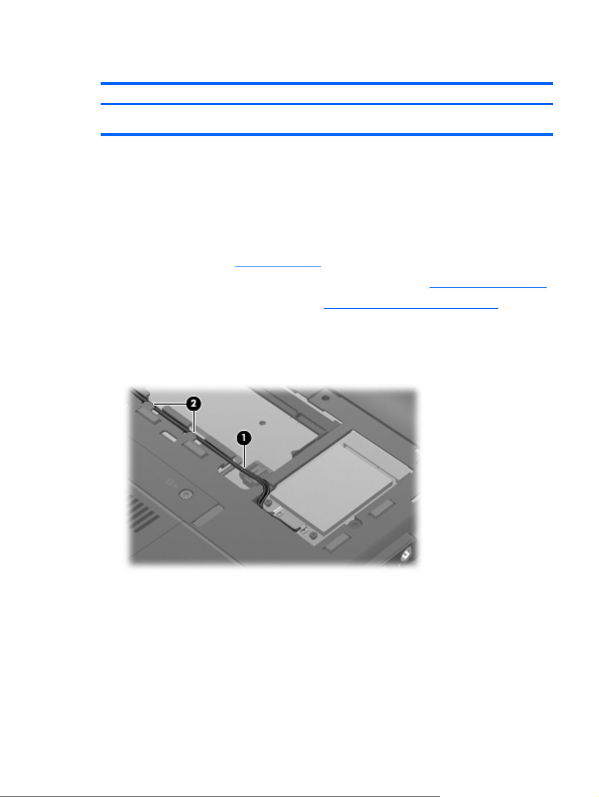
1. Close the computer and turn it upside down, with the rear panel toward you.
2. Remove the wireless antenna cables (1) from the clips (2) built into the base enclosure.
Component replacement procedures 47
Page 56
3. Remove the wedge-shaped screw covers (1) and the four Torx T8M2.0×5.0 screws (2) that secure
the display assembly to the computer.
NOTE: The rubber screw covers are available in the Rubber Kit, spare part number 481106-001.
4. Turn the computer right-side up, with the front toward you.
5. Open the computer.
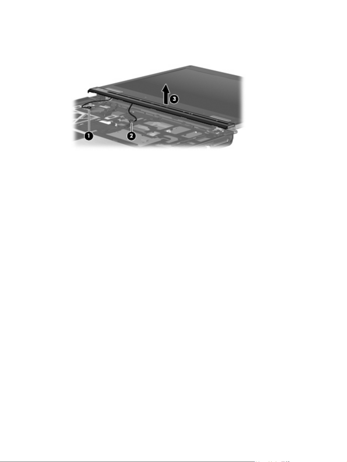
6. Remove the Torx8 T8M2.5×6.0 screw (1) that secures the display panel cable ground loop to the
left hinge.
7. Disconnect the display panel cable (2) from the system board.
8. Remove the wireless antenna cables (3) from the clips and routing channels (4) built into the top
cover.
48 Chapter 4 Removal and replacement procedures
Page 57

9. Disconnect the microphone cable (5) from the system board.
CAUTION: The display assembly will be unsupported when the following screws are removed.
To prevent damage to the display assembly, support it before removing the screws.
10. Remove the T8M2.5×6.0 screw (1) that secures the display assembly to the computer.
11. Lift the display assembly (2) straight up and remove it.
NOTE: The display bezel is secured to the display assembly by and by the screws identified in
step 12. After the bezel is removed, any residue of the adhesive should be cleaned from the inside
edge of the bezel and the display panel metal frame. Then the new adhesive strip material should
be put in place.
New adhesive strip material is included in all display bezel, display hinge, display panel cable, and
display enclosure spare part kits, and is also available using spare part number 497013-001. This
spare part kit includes of two different lengths. The longer are installed on the display bezel and
panel top and bottom edges. The shorter are installed on the display bezel and panel left and right
edges.
Component replacement procedures 49
Page 58

12. If it is necessary to replace the display bezel, display hinges, display panel cable, or display
enclosure, remove the four rubber screw covers (1) and (2) and the four Torx T8M2.5×6.0
screws (3) that secure the display bezel to the display assembly.
NOTE: The rubber screw covers (1) on the display bezel top edge are thicker than the rubber
screw covers (2) on the display bezel bottom edge. The rubber screw covers are available in the
Rubber Kit, spare part number 481106-001.
13. Flex the inside edges of the bottom (1), left and right sides (2), and the top (3) of the display bezel
until the bezel disengages from the display enclosure.
14. Remove the display bezel (4). The display bezel is available using spare part number
481097-001.
15. If it is necessary to replace the display hinges, remove the two Phillips PM2.5×4.0 screws (1) that
secure the display panel to the display enclosure.
50 Chapter 4 Removal and replacement procedures
Page 59
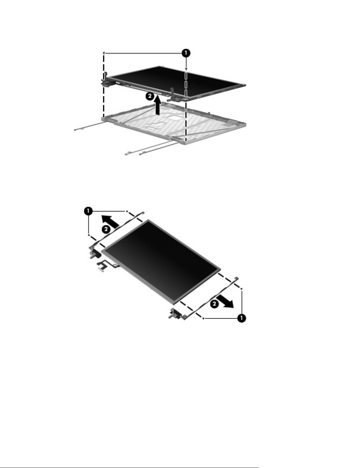
16. Remove the display panel (2).
17. Remove the two Phillips PM2.0×4.0 screws (1) that secure each display hinge to the display
panel.
18. Remove the display hinges (2). The left and right display hinges are available using spare part
number 481098-001.
19. If it is necessary to replace the display panel cable, turn the display panel upside down, with the
display panel bottom edge toward you.
20. Remove the support tape (1) that secures the top edge of the display panel cable to the display
panel.
21. Disconnect the display panel cable (2) from the display panel.
22. Disconnect the display panel cable (3) from the display inverter.
Component replacement procedures 51
Page 60

23. Remove the display panel cable (4). The display panel cable is available using spare part number
Reverse this procedure to reassemble and install the display assembly.
Top cover
Description Spare part number
481099-001.
Top cover 481111-001
Before removing the top cover, follow these steps:
1. Shut down the computer.
2. Disconnect all external devices connected to the computer.
3. Disconnect the power from the computer by first unplugging the power cord from the AC outlet and
then unplugging the AC adapter from the computer.
4. Remove the battery (see
Battery on page 30).
5. Remove the following components:
a. Flash drive (see
b. Optical drive (see
c. Switch cover and keyboard (see
d. Display assembly (see
Flash drive on page 36)
Optical drive on page 38)
Switch cover and keyboard on page 40)
Display assembly on page 47)
Remove the top cover:
1. Turn the computer upside down, with the front toward you.
2. Loosen the captive Phillips PM2.5×6.0 screw (1) that secures the Bluetooth module compartment
cover to the computer.
52 Chapter 4 Removal and replacement procedures
Page 61

3. Lift the front edge of the Bluetooth module compartment cover (2), swing it up and forward, and
remove the cover.
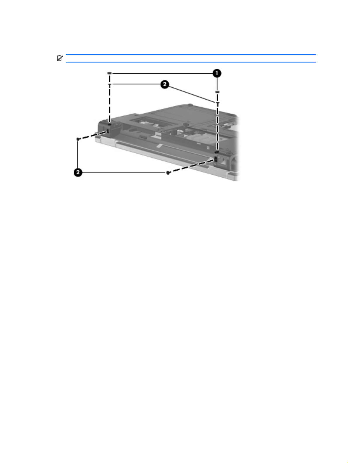
4. Remove the following screw covers and screws:
(1) Four rubber screw covers. The rubber screw covers are included in the Rubber Kit, spare part
number 481106-001.
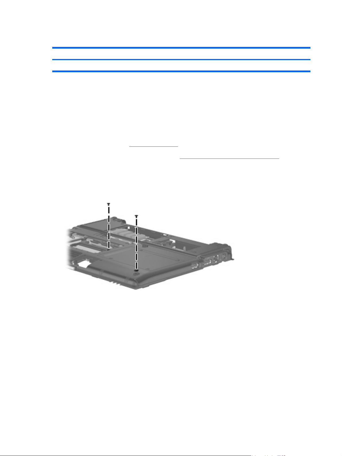
(2) Six Torx T8M2.5×6.0 screws.
(3) One Phillips PM2.0×6.0 screw.
(4) One Torx T8M2.0×5.0 screw.
5. Turn the computer right-side up, with the front toward you.
6. Release the ZIF connector to which the TouchPad cable is attached and disconnect the TouchPad
cable (1) from the system board.
Component replacement procedures 53
Page 62

7. Remove the two Torx T8M2.5×6.0 screws (2) and the Phillips PM2.0×6.0 screw (3) that secure the
top cover to the computer.
8. Lift the rear edge of the top cover (1) and swing it up and forward until it rests at an angle.
9. Lift the front edge of the top cover (2) until it disengages from the base enclosure.
10. Remove the top cover.
Reverse this procedure to install the top cover.
54 Chapter 4 Removal and replacement procedures
Page 63

LED board
Description Spare part number
LED board (includes cable and Mylar cover) 481090-001
Before removing the LED board, follow these steps:
1. Shut down the computer.
2. Disconnect all external devices connected to the computer.
3. Disconnect the power from the computer by first unplugging the power cord from the AC outlet and
then unplugging the AC adapter from the computer.
4. Remove the battery (see
Battery on page 30).
5. Remove the following components:
a. Flash drive (see
b. Optical drive (see
c. Switch cover and keyboard (see
d. Display assembly (see
e. Bluetooth module compartment cover (see
f. Top cover (see
Flash drive on page 36)
Optical drive on page 38)
Switch cover and keyboard on page 40)
Display assembly on page 47)
Top cover on page 52)
Top cover on page 52)
Remove the LED board:
1. Release the ZIF connector (1) to which the LED board cable is attached and disconnect the LED
board cable (2) from the system board.
2. Remove the LED board (3) from the clip in the base enclosure.
NOTE: The LED board cable is included with the LED board and is also available in the Cables Kit,
spare part number 481092-001.
Component replacement procedures 55
Page 64
Reverse the above procedure to install the LED board.
Speaker
Before removing the speaker, follow these steps:
1. Shut down the computer.
2. Disconnect all external devices connected to the computer.
3. Disconnect the power from the computer by first unplugging the power cord from the AC outlet and
Description Spare part number
Speaker 481109-001
then unplugging the AC adapter from the computer.
4. Remove the battery (see
Battery on page 30).
5. Remove the following components:
a. Flash drive (see
b. Optical drive (see
c. Switch cover and keyboard (see
d. Display assembly (see
e. Top cover (see
Flash drive on page 36)
Optical drive on page 38)
Switch cover and keyboard on page 40)
Display assembly on page 47)
Top cover on page 52)
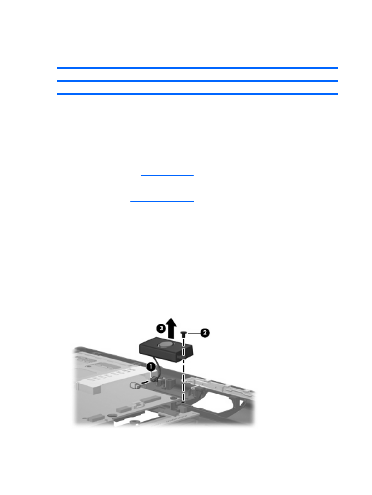
Remove the speaker:
1. Disconnect the speaker cable (1) from the system board.
2. Remove the Phillips PM2.0×4.0 screw (2) that secures the speaker to the base enclosure.
3. Remove the speaker (3) from the base enclosure.
Reverse this procedure to install the speaker.
56 Chapter 4 Removal and replacement procedures
Page 65

System board
Description Spare part number
System board (includes processor, replacement thermal material, and replacement thermal
material cleaning kit)
481091-001
Before removing the system board, follow these steps:
1. Shut down the computer.
2. Disconnect all external devices connected to the computer.
3. Disconnect the power from the computer by first unplugging the power cord from the AC outlet and
then unplugging the AC adapter from the computer.
4. Remove the battery (see
Battery on page 30).
5. Remove the following components:
a. Flash drive (see
b. WLAN module (see
c. Optical drive (see
d. Switch cover and keyboard (see
e. Display assembly (see
Flash drive on page 36)
WLAN module on page 34)
Optical drive on page 38)
Switch cover and keyboard on page 40)
Display assembly on page 47)
f. Top cover (see
Top cover on page 52)
When replacing the system board, be sure that the following components are removed from the defective
system board and installed on the replacement system board:
Memory module (see
●
Flash drive (see
●
Heat sink (see
●
WLAN module (see
●
Memory module on page 32)
Flash drive on page 36)
Heat sink on page 63)
WLAN module on page 34)
Remove the system board:
1. Release the ZIF connector to which the front LED board cable is attached and disconnect the front
LED board cable (1) from the system board.
2. Disconnect the speaker cable (2) from the system board.
Component replacement procedures 57
Page 66
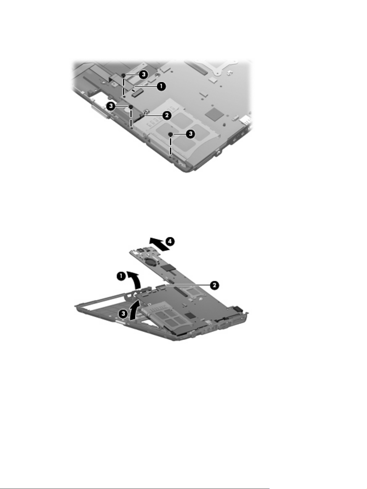
3. Remove the three Torx8 T8M2.5×6.0 screws (3) that secure the system board to the base
enclosure.
4. Flex the left side of the base enclosure (1) until the RJ-11 jack and USB ports are clear of the
openings in the base enclosure.
5. Use the optical drive connector (2) to lift the left side of the system board (3) until it rests at an
angle.
6. Remove the system board (4) from the base enclosure by sliding it up and to the left.
Reverse the preceding procedure to install the system board.
58 Chapter 4 Removal and replacement procedures
Page 67
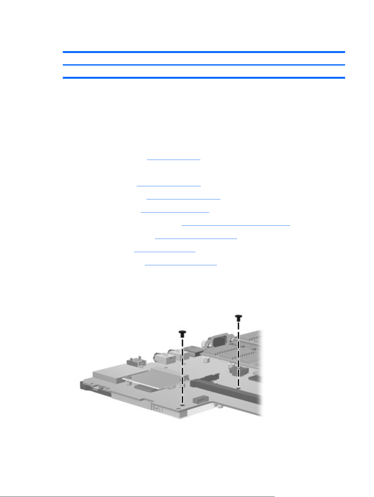
PC Card assembly
Description Spare part number
PC Card assembly 481104-001
Before removing the PC Card assembly, follow these steps:
1. Shut down the computer.
2. Disconnect all external devices connected to the computer.
3. Disconnect the power from the computer by first unplugging the power cord from the AC outlet and
then unplugging the AC adapter from the computer.
4. Remove the battery (see
Battery on page 30).
5. Remove the following components:
a. Flash drive (see
b. WLAN module (see
c. Optical drive (see
d. Switch cover and keyboard (see
e. Display assembly (see
f. Top cover (see
g. System board (see
Flash drive on page 36)
WLAN module on page 34)
Optical drive on page 38)
Switch cover and keyboard on page 40)
Display assembly on page 47)
Top cover on page 52)
System board on page 57)
Remove the PC Card assembly:
1. Turn the system board upside down, with the front toward you.
2. Remove the two Phillips PM2.0×5.0 screws that secure the PC Card assembly to the system board.
3. Turn the system board upside down, with the rear toward you.
Component replacement procedures 59
Page 68
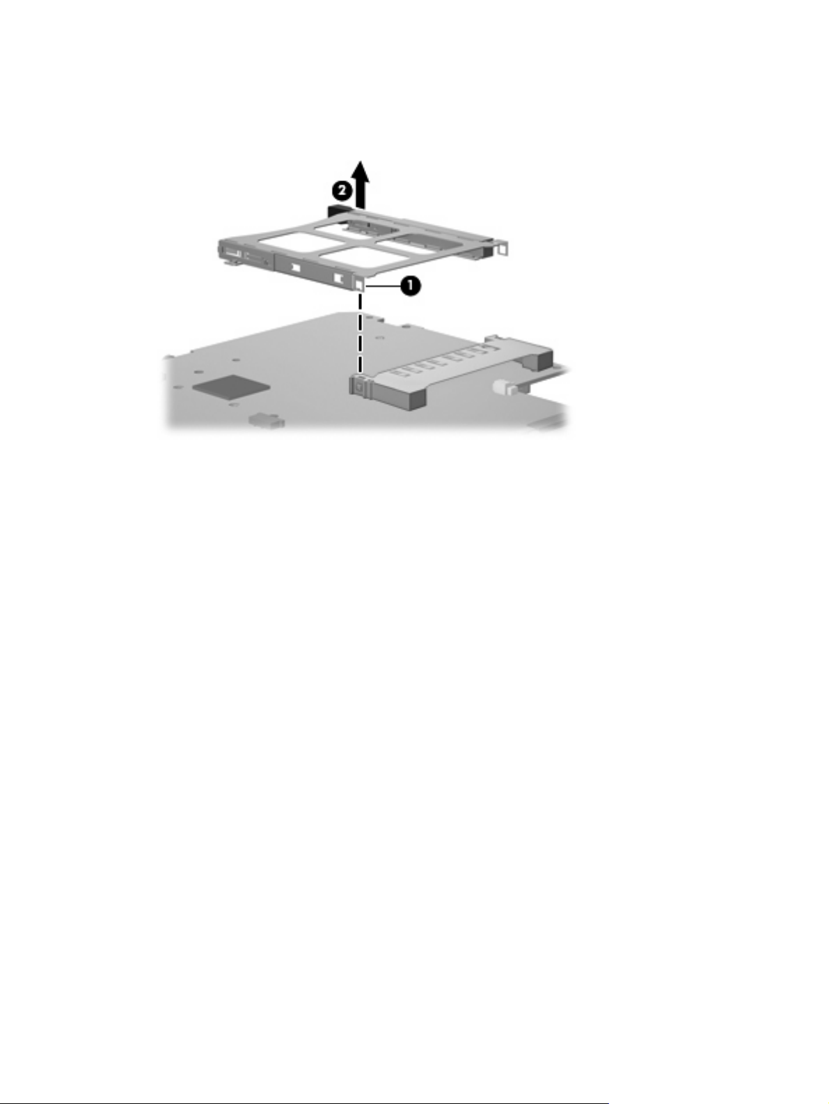
4. Detach the slot (1) on the PC Card assembly from the tab on the PC Card assembly connector on
the system board.
5. Remove the PC Card assembly (2).
Reverse this procedure to install the PC Card assembly.
60 Chapter 4 Removal and replacement procedures
Page 69

Modem module
NOTE: The modem module spare part kits do not include a modem module cable. The modem module
cable is included in the Cable Kit, spare part number 481092-001. See
Cable Kit spare part number information.
Description Spare part number
For use in all countries and regions except Australia and New Zealand 461750-001
For use only in Australia and New Zealand 461750-002
Before removing the modem module, follow these steps:
1. Shut down the computer.
2. Disconnect all external devices connected to the computer.
3. Disconnect the power from the computer by first unplugging the power cord from the AC outlet and
then unplugging the AC adapter from the computer.
Cable Kit on page 20 for more
4. Remove the battery (see
Battery on page 30).
5. Remove the following components:
a. Flash drive (see
b. WLAN module (see
c. Optical drive (see
d. Switch cover and keyboard (see
e. Display assembly (see
f. Top cover (see
g. System board (see
Flash drive on page 36)
WLAN module on page 34)
Optical drive on page 38)
Switch cover and keyboard on page 40)
Display assembly on page 47)
Top cover on page 52)
System board on page 57)
Remove the modem module:
1. Turn the system board upside down, with the front toward you.
2. Remove the two Phillips PM2.0×4.0 screws (1) that secure the modem module to the system board.
3. Lift the modem module (2) straight up until it disconnects from the system board.
Component replacement procedures 61
Page 70
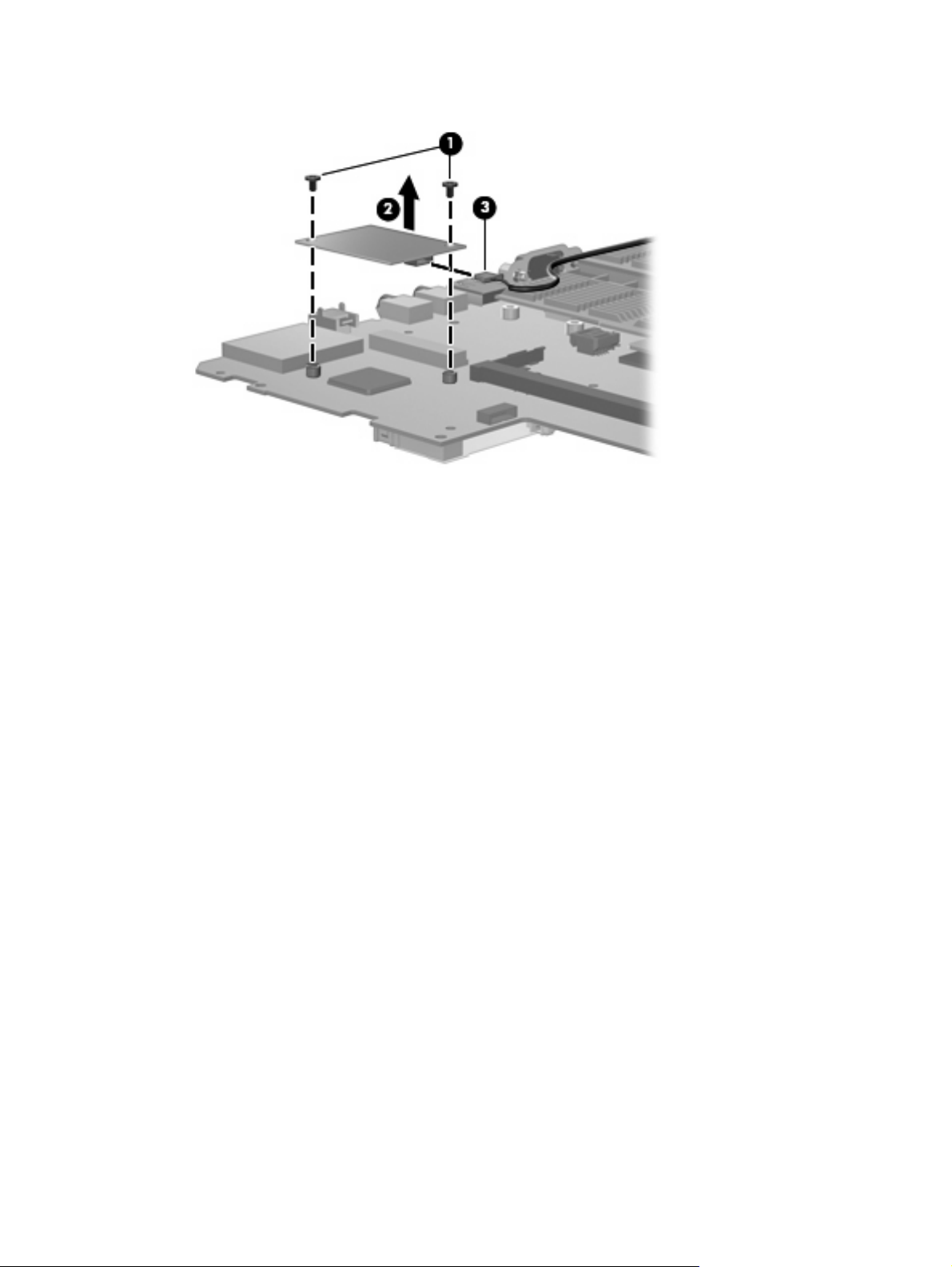
4. Disconnect the modem module cable (3) from the modem module.
5. Remove the modem module.
Reverse this procedure to install the modem module.
62 Chapter 4 Removal and replacement procedures
Page 71

Heat sink
Description Spare part number
Heat sink (includes replacement thermal material and replacement thermal material cleaning kit) 481110-001
Before removing the heat sink, follow these steps:
1. Shut down the computer.
2. Disconnect all external devices connected to the computer.
3. Disconnect the power from the computer by first unplugging the power cord from the AC outlet and
then unplugging the AC adapter from the computer.
4. Remove the battery (see
Battery on page 30).
5. Remove the following components:
a. Flash drive (see
b. WLAN module (see
c. Optical drive (see
d. Switch cover and keyboard (see
e. Display assembly (see
f. Top cover (see
g. System board (see
Flash drive on page 36)
WLAN module on page 34)
Optical drive on page 38)
Switch cover and keyboard on page 40)
Display assembly on page 47)
Top cover on page 52)
System board on page 57)
Remove the heat sink:
1. Turn the system board upside down, with the front toward you.
2. Following the 1, 2, 3, 4 sequence stamped into the heat sink, loosen the four Torx8 T8M2.0×10.0
screws (1) that secure the heat sink to the system board.
Component replacement procedures 63
Page 72
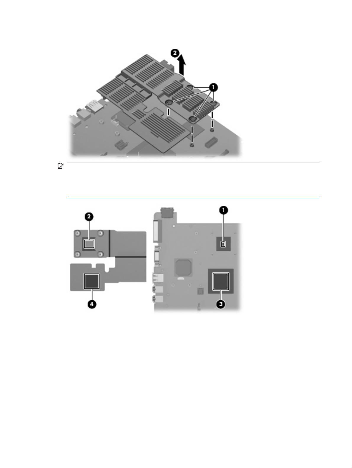
3. Remove the heat sink (2).
NOTE: The thermal material must be thoroughly cleaned from the surfaces of the heat sink and
system board each time the heat sink is removed. Thermal paste is located on the processor (1)
and the section of the heat sink that services it (2). Thermal pads are located on the Northbridge
chip (3) and the section of the heat sink that services it (4). Replacement thermal material is
included with all heat sink and system board spare part kits.
Reverse this procedure to install the heat sink.
64 Chapter 4 Removal and replacement procedures
Page 73

5 Computer Setup
Starting Computer Setup
Computer Setup is a preinstalled ROM-based utility that can be used even when the operating system
is not working or will not load.
NOTE: Some of the Computer Setup menu items listed in this guide may not be supported by your
computer.
NOTE: Pointing devices are not supported in Computer Setup. You must use the keyboard to navigate
and make selections.
To start Computer Setup, follow these steps:
1. Turn on or restart the computer.
2. Before Windows opens and while the “F10=ROM Based Setup” message is displayed in the lower-
left corner of the screen, press f10.
Starting Computer Setup 65
Page 74

Using Computer Setup
Navigating and selecting in Computer Setup
The information and settings in Computer Setup are accessed from the File, Security, Diagnostics, and
System Configuration menus.
1. Open Computer Setup by turning on or restarting the computer, and then pressing f10 while the
"F10 = ROM Based Setup" message is displayed in the lower-left corner of the screen.
Because Computer Setup is not Windows-based, it does not support the TouchPad. Navigation
and selection are by keystroke:
To choose a menu or a menu item, use the arrow keys.
●
To select an item, press enter.
●
To close open dialog boxes and return to the main Computer Setup screen, press esc.
●
To view navigation information, press f1.
●
To change the language, press f2.
●
2. Select the File, Security, Diagnostics, or System Configuration menu.
3. To exit Computer Setup, choose one of the following methods:
To exit Computer Setup without saving your preferences, use the arrow keys to select File >
●
Ignore Changes and Exit. Then follow the instructions on the screen.
To save your preferences and exit Computer Setup, use the arrow keys to select File > Save
●
Changes and Exit. Then follow the instructions on the screen.
Your preferences go into effect when the computer restarts.
Restoring factory settings in Computer Setup
To return all settings in Computer Setup to the values that were set at the factory, follow these steps:
1. Open Computer Setup by turning on or restarting the computer, and then pressing f10 while the
"F10 = ROM Based Setup" message is displayed in the lower-left corner of the screen.
2. Use the arrow keys to select File > Restore defaults, and then press enter.
3. When the confirmation dialog box opens, press f10.
4. To save your preferences and exit Computer Setup, use the arrow keys to select File > Save
Changes and Exit. Then follow the instructions on the screen.
Your preferences go into effect when the computer restarts.
NOTE: Your password settings and security settings are not changed when you restore the factory
settings.
66 Chapter 5 Computer Setup
Page 75

Computer Setup menus
The menu tables in this section provide an overview of Computer Setup options.
NOTE: Some of the Computer Setup menu items listed in this chapter may not be supported by your
computer.
File menu
Select To do this
System information
Restore defaults Replace the configuration settings in Computer Setup with the original factory
Ignore changes and exit Cancel any changes entered during the current session. Then exit and restart the
Save changes and exit Save any changes entered during the current session. Then exit and restart the
Security menu
Select To do this
Setup Password Enter, change, or delete a setup password.
Power-On Password Enter, change, or delete a power-on password.
Password Options
View identification information for the computer and the batteries in the
●
system.
View specification information for the processor, cache and memory size,
●
system ROM, video revision, and keyboard controller version.
settings. (Password settings and security settings are not changed when you
restore the factory settings.)
computer.
computer. Your changes go into effect when the computer restarts.
Enable/disable stringent security.
●
Enable/disable password requirement on computer restart.
●
System IDs Enter user-defined computer asset tracking number and ownership tag.
Diagnostics menu
Select To do this
Memory Check Run a comprehensive check on system memory.
Computer Setup menus 67
Page 76

System Configuration menu
NOTE: Some of the listed System Configuration options may not be supported by your computer.
Select To do this
Language (or press f2) Change the Computer Setup language.
Boot options
Device configurations
Built-In Device Options
Set f9, f10, and f12 delay when starting up.
●
Enable/disable CD-ROM boot.
●
Enable/disable floppy boot.
●
Enable/disable internal network adapter boot.
●
Enable/disable MultiBoot, which sets a boot order that can include most boot
●
devices in the system.
Set the boot order.
●
Swap the functions of the fn key and left ctrl key.
●
Enable/disable USB legacy support. When enabled, USB legacy support
●
allows the following:
Use of a USB keyboard in Computer Setup even when a Windows
◦
operating system is not running.
Startup from bootable USB devices, including a hard drive, diskette
◦
drive, or optical drive connected by a USB port to the computer.
Enable/disable embedded WLAN Device Radio.
●
Enable/disable network Interface Controller (LAN)
●
Enable/disable LAN/WAN switching.
●
Enable/disable Wake on LAN.
●
Port Options
Enable/disable the optical disc drive.
●
Enable/disable the USB port.
●
Enable/disable the PC Card slot.
●
Enable/disable flash media reader.
●
68 Chapter 5 Computer Setup
Page 77

6 Specifications
Computer specifications
Metric U.S.
Dimensions
Depth
Width 28.23 cm 11.11 in
Height (front to rear) 2.52 to 3.40 cm 0.99 to 1.34 in
Weight
Equipped with DVD-ROM Drive, 9-cell battery, and WLAN
module
Equipped with DVD-ROM Drive, 6-cell battery, and WLAN
module
Equipped with DVD-ROM Drive, 3-cell battery, and WLAN
module
Equipped with 3-cell battery and WLAN module 1.29 kg 2.84 lbs
Input power
Operating voltage
Operating current 3.50 A
Temperature
Operating (reading to optical disc)
Nonoperating -20°C to 60°C -4°F to 140°F
Relative humidity (noncondensing)
21.43 cm 8.44 in
1.79 kg 3.95 lbs
1.64 kg 3.62 lbs
1.48 kg 3.26 lbs
18.5 V dc @ 3.50 A – 65 W
0°C to 35°C 32°F to 95°F
Operating
Nonoperating 5% to 95%
Maximum altitude (unpressurized)
Operating (14.7 to 10.1 psia)
Nonoperating (14.7 to 4.4 psia) -15 m to 12,192 m -50 ft to 40,000 ft
Shock
Operating
10% to 90%
-15 m to 3,048 m -50 ft to 10,000 ft
125 g, 2 ms, half-sine
Computer specifications 69
Page 78

Metric U.S.
Nonoperating 200 g, 2 ms, half-sine
Random vibration
Operating
Nonoperating 1.50 g zero-to-peak, 10 Hz to 500 Hz, 0.5 oct/min sweep rate
NOTE: Applicable product safety standards specify thermal limits for plastic surfaces. The computer operates well within this
range of temperatures.
0.75 g zero-to-peak, 10 Hz to 500 Hz, 0.25 oct/min sweep rate
12.1-inch, WXGA display specifications
Metric U.S.
Dimensions
Height
Width 26.2 cm 10.3 in
Diagonal 30.8 cm 12.1 in
Number of colors Up to 16.8 million
Contrast ratio 250:1 (typical)
Brightness 180 nits (typical)
Pixel resolution
Pitch
16.9 cm 6.7 in
0.279 × 0.279 mm
Format 1280 × 800
Configuration RGB vertical stripe
Backlight Edge lit
Character display 80 × 25
Total power consumption 4.0 W
Viewing angle +/-40 horizontal, +20/–40° vertical (typical)
70 Chapter 6 Specifications
Page 79

8X Max DVD-ROM Drive specifications
Applicable disc DVD-ROM (DVD-5, DVD-9, DVD-10, DVD-18), CD-ROM (Mode 1 and 2), CD Digital
Audio, CD-XA ready (Mode 2, Form 1 and Form 2), CD-I (Mode 2, Form 1 and Form
2), CD-RW, Photo CD (single and multisession), and CD-Bridge
Access time
Random < 100 ms < 125 ms
Cache buffer 512 KB
Data transfer rate
CD-R (24X)
CD-RW (10X) 1,500 KB/sec (150 KB/s at 1X CD rate)
CD-ROM (24X) 3,600 KB/sec (150 KB/s at 1X CD rate)
DVD (8X) 10,800 KB/sec (1,352 KB/s at 1X DVD rate)
Multiword DMA mode 2 16.6 MB/sec
CD DVD
3,600 KB/sec (150 KB/s at 1X CD rate)
8X Max DVD-ROM Drive specifications 71
Page 80

System DMA specifications
Hardware DMA System function
DMA0 Not applicable
DMA1* Not applicable
DMA2* Not applicable
DMA3 Not applicable
DMA4 Direct memory access controller
DMA5* Available for ExpressCard
DMA6 Not assigned
DMA7 Not assigned
*ExpressCard controller can use DMA 1, 2, or 5.
72 Chapter 6 Specifications
Page 81

System interrupt specifications
Hardware IRQ System function
IRQ0 System timer
IRQ1 Standard 101-/102-Key or Microsoft® Natural Keyboard
IRQ2 Cascaded
IRQ3 Intel 82801DB/DBM USB2 Enhanced Host Controller—24CD
IRQ4 COM1
IRQ5* Conexant AC—Link Audio Intel 82801DB/DBM SMBus Controller—24C3 Data Fax
Modem with SmartCP
IRQ6 Diskette drive
IRQ7* Parallel port
IRQ8 System CMOS/real-time clock
IRQ9* Microsoft ACPI-compliant system
IRQ10* Intel USB UHCI controller—24C2
Intel 82852/82855 GM/GME Graphic Controller
Realtek RTL8139 Family PCI Fast Ethernet Controller
IRQ11 Intel USB EHCI controller—24CD
Intel USB UHCI controller—24C4
Intel USB UHCI controller—24C7
Intel Pro/Wireless 2200BG
TI OHCI 1394 host controller
TI PCI1410 CardBus controller
IRQ12 Synaptics PS/2 TouchPad
IRQ13 Numeric data processor
IRQ14 Primary IDE channel
IRQ15 Secondary IDE channel
*Default configuration; audio possible configurations are IRQ5, IRQ7, IRQ9, IRQ10, or none.
NOTE: ExpressCards may assert IRQ3, IRQ4, IRQ5, IRQ7, IRQ9, IRQ10, IRQ11, or IRQ15. Either the infrared or the serial
port may assert IRQ3 or IRQ4.
System interrupt specifications 73
Page 82

System I/O address specifications
I/O address (hex) System function (shipping configuration)
000 - 00F DMA controller no. 1
010 - 01F Unused
020 - 021 Interrupt controller no. 1
022 - 024 Opti chipset configuration registers
025 - 03F Unused
02E - 02F 87334 “Super I/O” configuration for CPU
040 - 05F Counter/timer registers
044 - 05F Unused
060 Keyboard controller
061 Port B
062 - 063 Unused
064 Keyboard controller
065 - 06F Unused
070 - 071 NMI enable/RTC
072 - 07F Unused
080 - 08F DMA page registers
090 - 091 Unused
092 Port A
093 - 09F Unused
0A0 - 0A1 Interrupt controller no. 2
I/O Address (hex) System Function (shipping configuration)
0A2 - 0BF Unused
0C0 - 0DF DMA controller no. 2
0E0 - 0EF Unused
0F0 - 0F1 Coprocessor busy clear/reset
0F2 - 0FF Unused
100 - 16F Unused
170 - 177 Secondary fixed disk controller
178 - 1EF Unused
1F0 - 1F7 Primary fixed disk controller
1F8 - 200 Unused
201 Joystick (decoded in ESS1688)
202 - 21F Unused
74 Chapter 6 Specifications
Page 83

I/O address (hex) System function (shipping configuration)
220 - 22F Entertainment audio
230 - 26D Unused
26E - 26 Unused
278 - 27F Unused
280 - 2AB Unused
2A0 - 2A7 Unused
2A8 - 2E7 Unused
2E8 - 2EF Reserved serial port
2F0 - 2F7 Unused
2F8 - 2FF Infrared port
300 - 31F Unused
320 - 36F Unused
370 - 377 Secondary diskette drive controller
378 - 37F Parallel port (LPT1/default)
380 - 387 Unused
388 - 38B FM synthesizer—OPL3
38C - 3AF Unused
3B0 - 3BB VGA
3BC - 3BF Reserved (parallel port/no EPP support)
3C0 - 3DF VGA
3E0 - 3E1 ExpressCard controller in CPU
3E2 - 3E3 Unused
3E8 - 3EF Internal modem
3F0 - 3F7 “A” diskette controller
3F8 - 3FF Serial port (COM1/default)
CF8 - CFB PCI configuration index register (PCIDIVO-1)
CFC - CFF PCI configuration data register (PCIDIVO-1)
System I/O address specifications 75
Page 84

System memory map specifications
Size Memory address System function
640 KB 00000000-0009FFFF Base memory
128 KB 000A0000-000BFFFF Video memory
48 KB 000C0000-000CBFFF Video BIOS
160 KB 000C8000-000E7FFF Unused
64 KB 000E8000-000FFFFF System BIOS
15 MB 00100000-00FFFFFF Extended memory
58 MB 04800000-07FFFFFF Super extended memory
58 MB 04800000-07FFFFFF Unused
2 MB 08000000-080FFFFF Video memory (direct access)
4 GB 08200000-FFFEFFFF Unused
64 KB FFFF0000-FFFFFFFF System BIOS
76 Chapter 6 Specifications
Page 85

7 Screw listing
This section provides specification and reference information for the screws and screw locks used in
the computer. All screws listed in this section are available in the Screw Kit, spare part number
456615-001.
77
Page 86
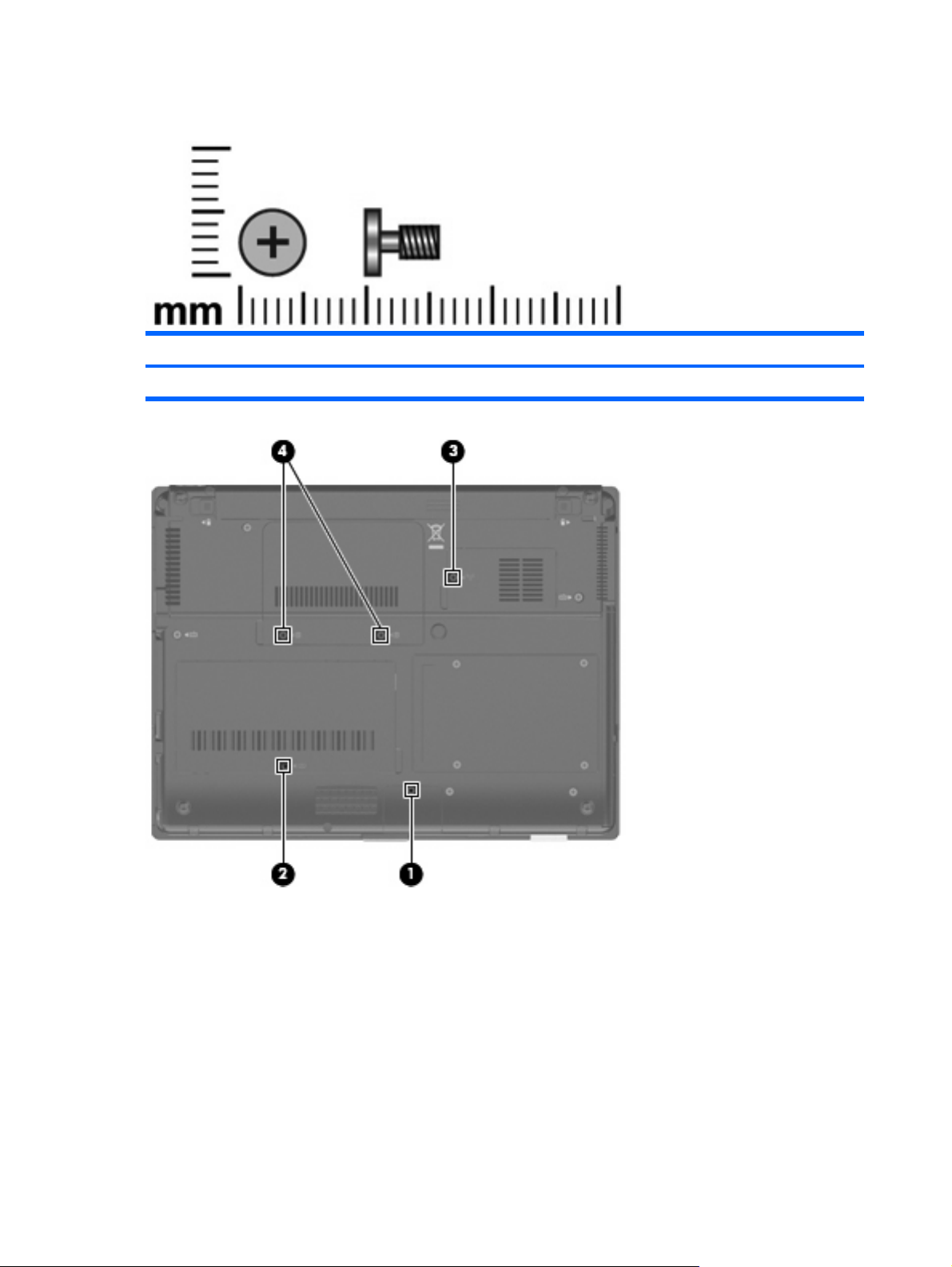
Phillips PM2.5×6.0 captive screw
Color Quantity Length Thread Head diameter
Black 5 6.0 mm 2.5 mm 5.0 mm
Where used:
(1) One captive screw that secures the Bluetooth module cover to the computer (screw is captured on
the cover by a C-clip)
(2) One captive screw that secures the memory module compartment cover to the computer (screw is
captured on the cover by a C-clip)
(3) One captive screw that secures the flash drive compartment cover to the computer (screw is captured
on the cover by a C-clip)
(4) Two captive screws that secure the rear cover to the computer (screws are secured by C-clips)
78 Chapter 7 Screw listing
Page 87

Phillips PM2.0×4.0 screw
Color Quantity Length Thread Head diameter
Silver 15 4.0 mm 2.0 mm 4.5 mm
Where used: 2 screws that secure the WLAN module to the base enclosure
Where used: 2 screws that secure the optical drive bracket to the optical drive
Phillips PM2.0×4.0 screw 79
Page 88

Where used: 2 screws that secure the optical drive bezel to the computer
Where used: 2 screws that secure the USB board to the optical drive bezel
Where used: 4 screws that secure the display hinges to the display panel
80 Chapter 7 Screw listing
Page 89
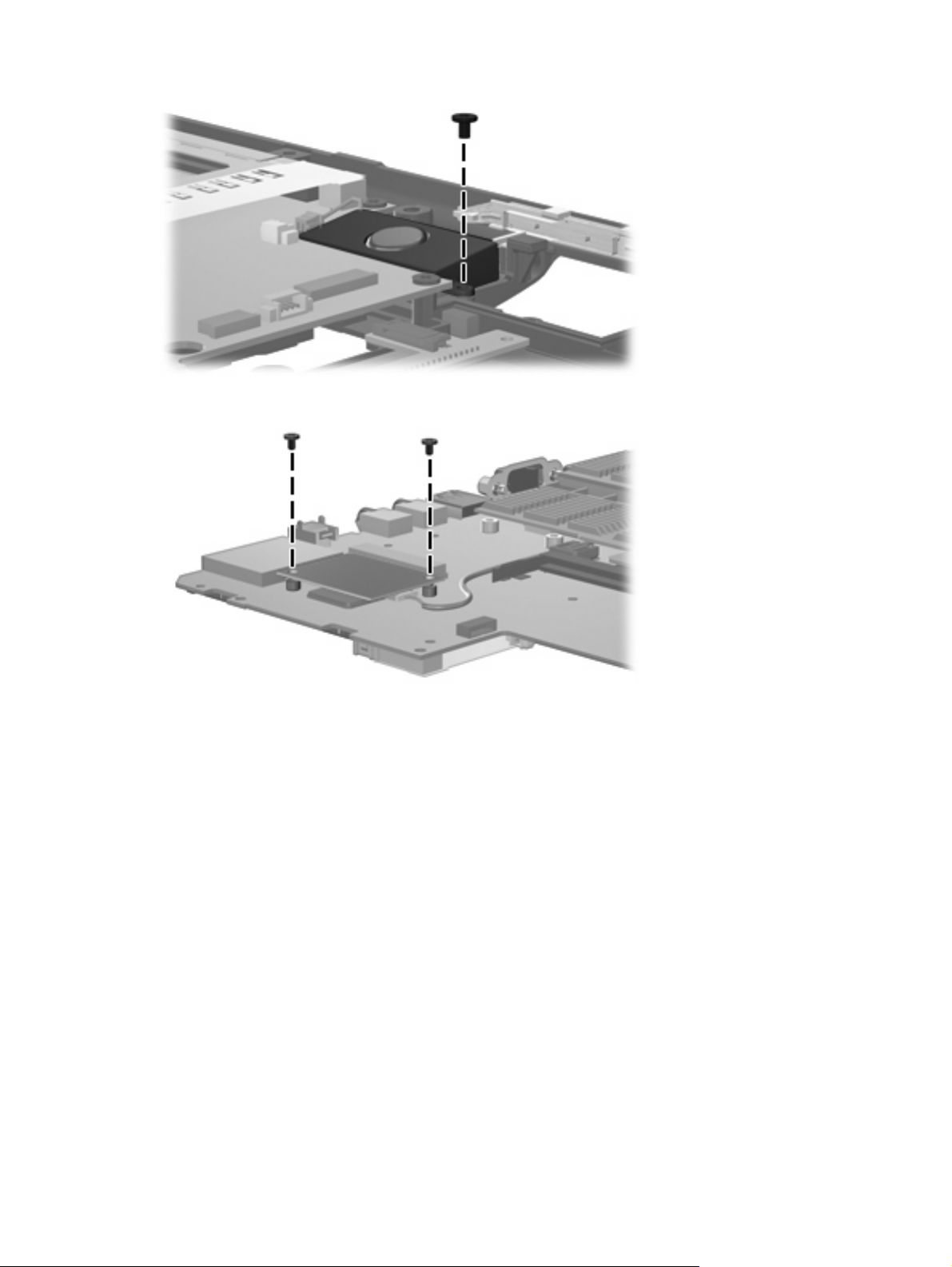
Where used: One screw that secures the speaker to the base enclosure
Where used: 2 screws that secure the modem module to the system board
Phillips PM2.0×4.0 screw 81
Page 90
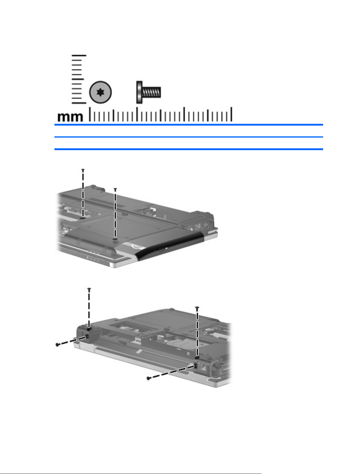
Torx T8M2.0×5.0 screw
Color Quantity Length Thread Head diameter
Black 7 5.0 mm 2.0 mm 4.5 mm
Where used: 2 screws that secure the optical drive to the computer
Where used: 4 screws that secure the display assembly to the computer
82 Chapter 7 Screw listing
Page 91
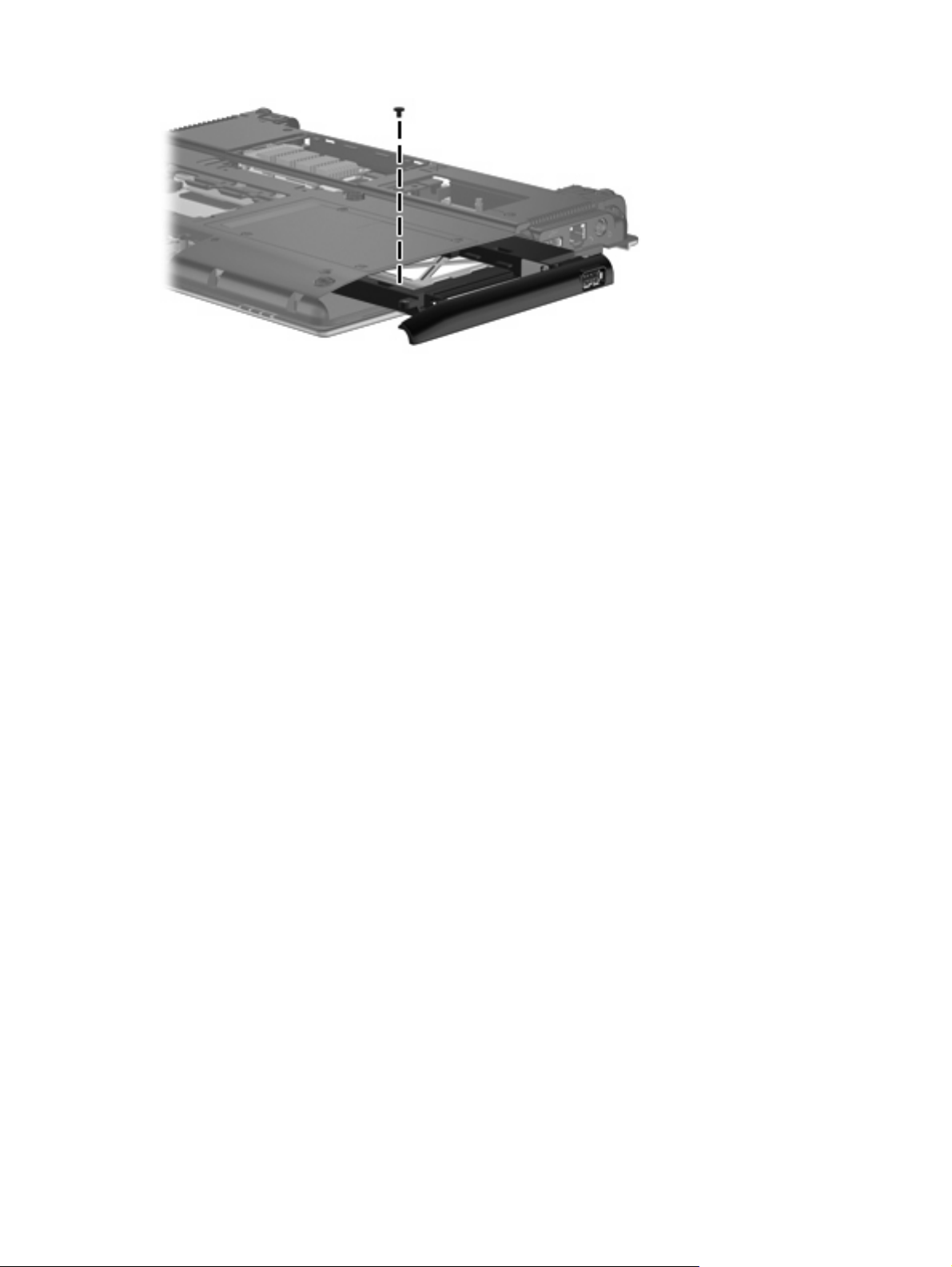
Where used: One screw that secures the top cover to the base enclosure
Torx T8M2.0×5.0 screw 83
Page 92

Torx T8M2.5×6.0 screw
Color Quantity Length Thread Head diameter
Black 18 6.0 mm 2.5 mm 5.0 mm
Where used: One screw that secures the switch cover to the computer
Where used: 2 screws that secure the display assembly to the computer
84 Chapter 7 Screw listing
Page 93

Where used: 4 screws that secure the display bezel to the display enclosure
Where used: 6 screws that secure the top cover to the base enclosure
Where used: 2 screws that secure the top cover to the base enclosure
Torx T8M2.5×6.0 screw 85
Page 94
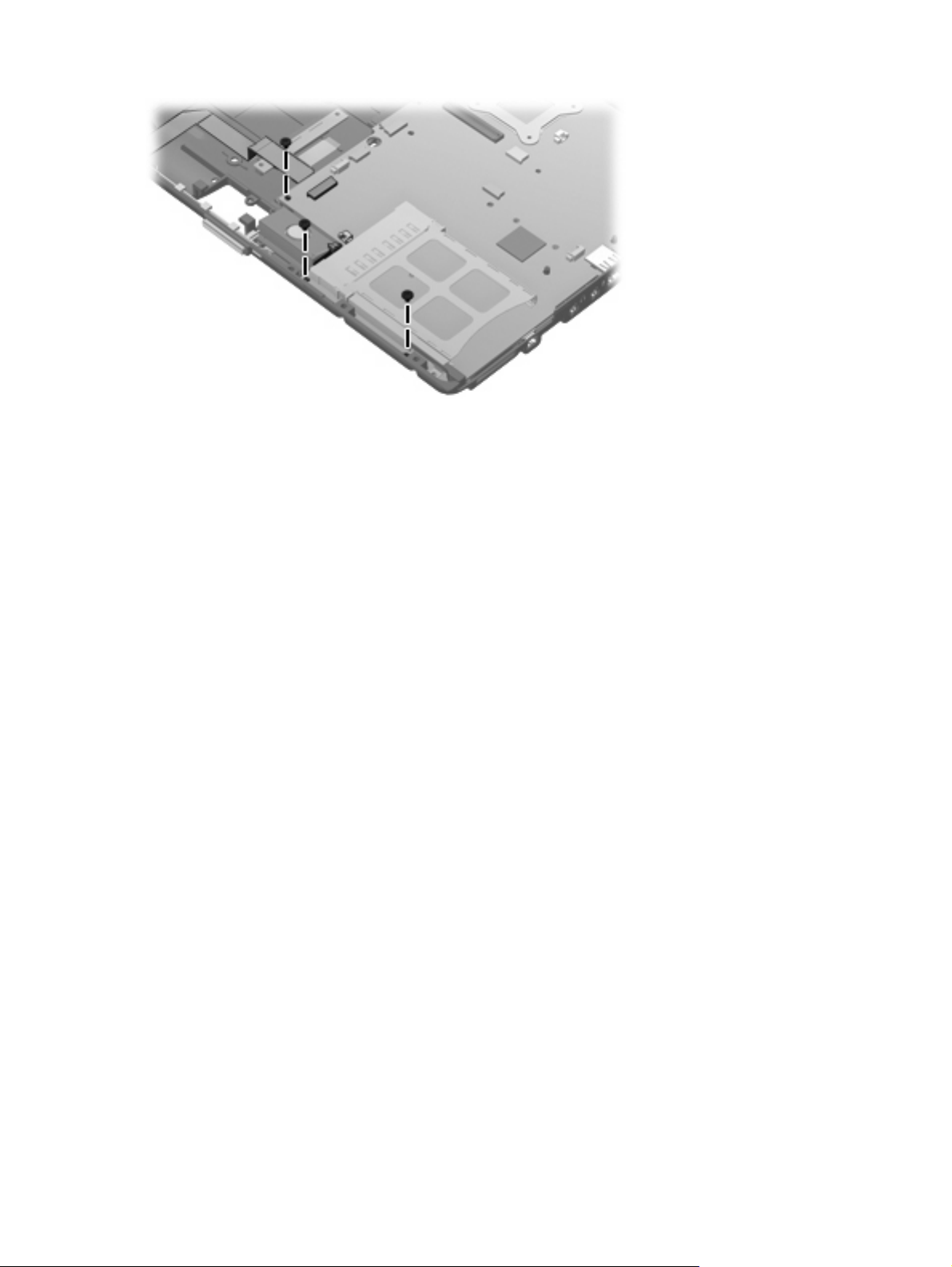
Where used: 3 screws that secure the system board to the base enclosure
86 Chapter 7 Screw listing
Page 95
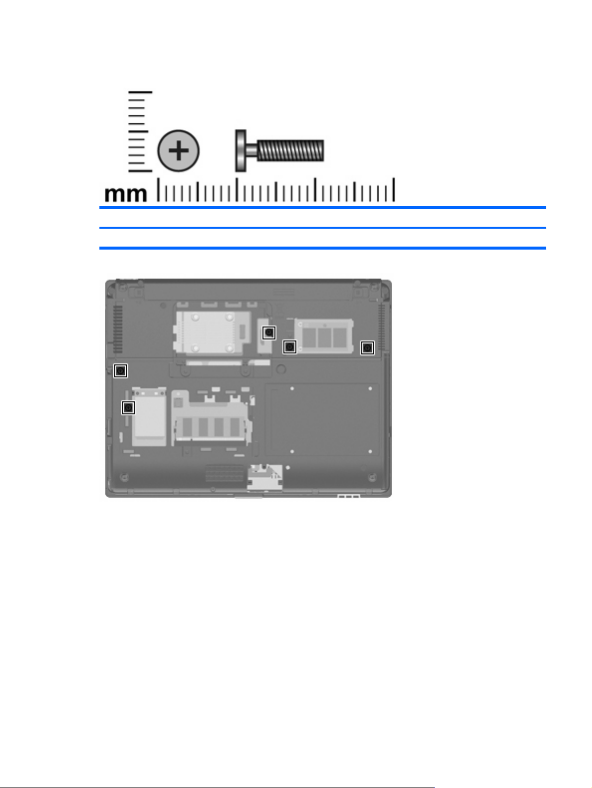
Phillips PM2.5×11.0 captive screw
Color Quantity Length Thread Head diameter
Black 5 11.0 mm 2.5 mm 5.0 mm
Where used: 5 captive screws that secure the keyboard to the computer (screws are secured by Cclips)
Phillips PM2.5×11.0 captive screw 87
Page 96
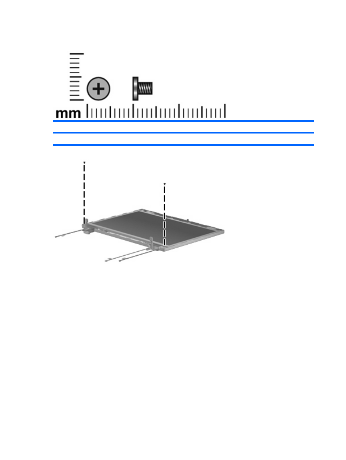
Phillips PM2.5×4.0 screw
Color Quantity Length Thread Head diameter
Black 2 4.0 mm 2.5 mm 5.0 mm
Where used: 2 screws that secure the display panel to the display enclosure
88 Chapter 7 Screw listing
Page 97
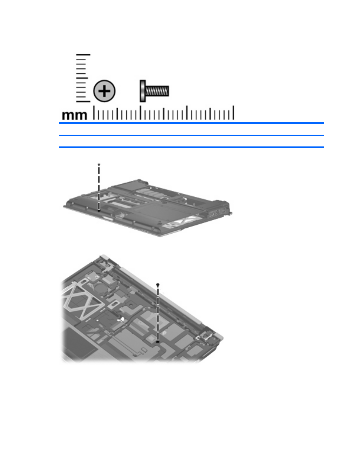
Phillips PM2.0×6.0 screw
Color Quantity Length Thread Head diameter
Black 2 6.0 mm 2.0 mm 4.5 mm
Where used: One screw that secures the top cover to the base enclosure
Where used: One screw that secures the top cover to the base enclosure
Phillips PM2.0×6.0 screw 89
Page 98
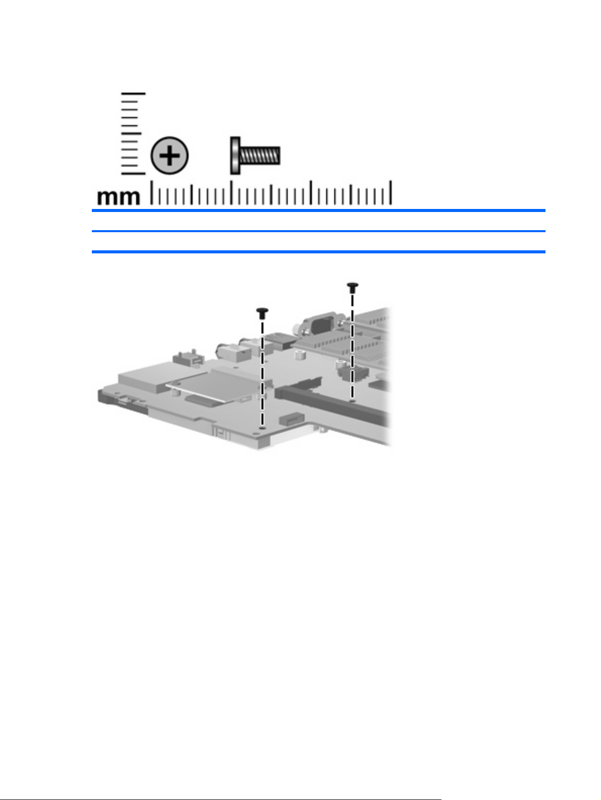
Phillips PM2.0×5.0 screw
Color Quantity Length Thread Head diameter
Silver 2 5.0 mm 2.0 mm 4.5 mm
Where used: 2 screws that secure the PC Card assembly to the system board
90 Chapter 7 Screw listing
Page 99

Torx T8M2.0×10.0 captive screw
Color Quantity Length Thread Heat width
Black 4 10.0 mm 2.0 mm 4.5 mm
Where used: 4 captive screws that secure the heat sink to the system board (screws are secured by Cclips)
Torx T8M2.0×10.0 captive screw 91
Page 100
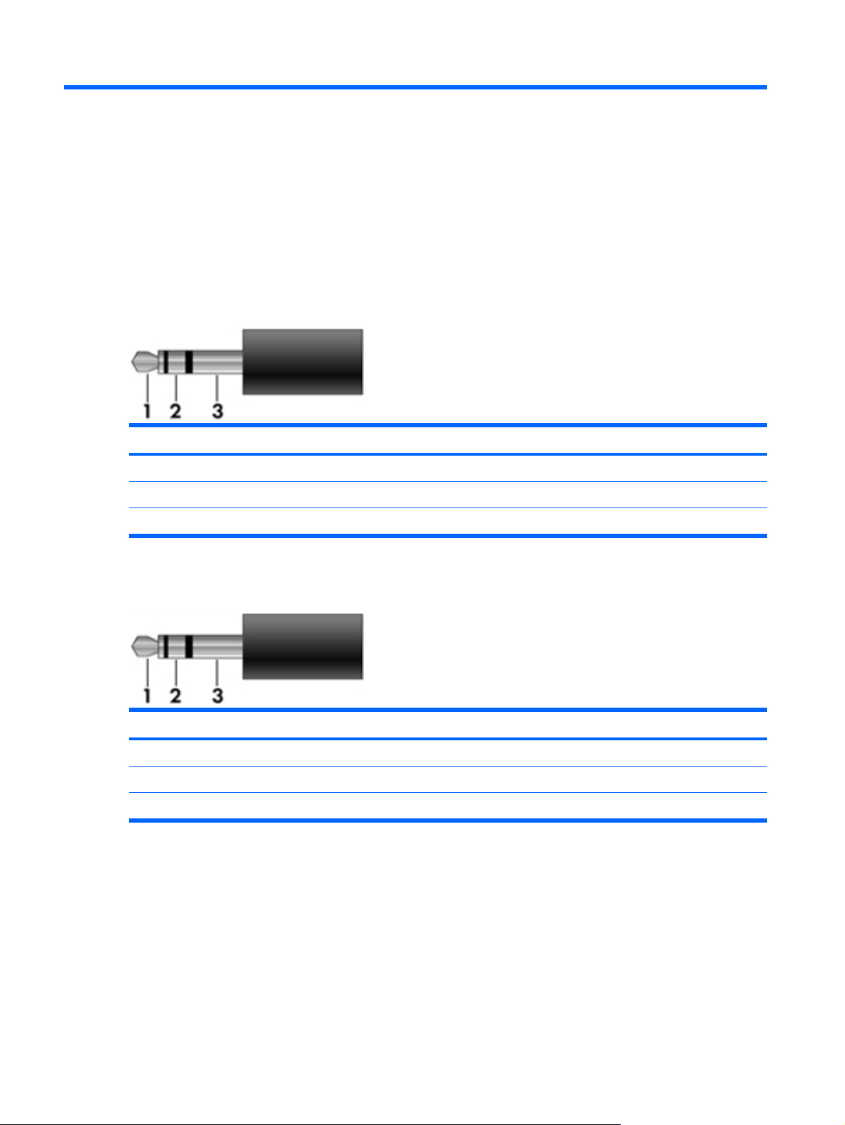
8 Connector pin assignments
Audio-out (headphone)
Pin Signal
1 Audio out, left channel
2 Audio out, right channel
3 Ground
Audio-in (microphone)
Pin Signal
1 Audio signal in
2 Audio signal in
3 Ground
92 Chapter 8 Connector pin assignments
 Loading...