

Page 1

HP 242 G1 Notebook PC
Maintenance and Service Guide
Page 2

© Copyright 2013 Hewlett-Packard
Development Company, L.P.
Bluetooth is a trademark owned by its
proprietor and used by Hewlett-Packard
Company under license. Intel and Core are
U.S. registered trademarks of Intel
Corporation. Microsoft and Windows are
U.S. registered trademarks of Microsoft
Corporation. SD Logo is a trademark of
its proprietor.
The information contained herein is subject
to change without notice. The only
warranties for HP products and services are
set forth in the express warranty statements
accompanying such products and services.
Nothing herein should be construed as
constituting an additional warranty. HP shall
not be liable for technical or editorial errors
or omissions contained herein.
First Edition: June 2013
Document Part Number: 725046-001
Product notice
This guide describes features that are
common to most models. Some features
may not be available on your computer.
Page 3

Important Notice about Customer Self-Repair Parts
CAUTION: Your computer includes Customer Self-Repair parts and parts that should only be
accessed by an authorized service provider. See Chapter 5, "Removal and replacement procedures
for Customer Self-Repair parts," for details. Accessing parts described in Chapter 6, "Removal and
replacement procedures for Authorized Service Provider only parts," can damage the computer or
void your warranty.
iii
Page 4

iv Important Notice about Customer Self-Repair Parts
Page 5

Safety warning notice
WARNING! To reduce the possibility of heat-related injuries or of overheating the device, do not
place the device directly on your lap or obstruct the device air vents. Use the device only on a hard,
flat surface. Do not allow another hard surface, such as an adjoining optional printer, or a soft
surface, such as pillows or rugs or clothing, to block airflow. Also, do not allow the AC adapter to
contact the skin or a soft surface, such as pillows or rugs or clothing, during operation. The device
and the AC adapter comply with the user-accessible surface temperature limits defined by the
International Standard for Safety of Information Technology Equipment (IEC 60950).
v
Page 6

vi Safety warning notice
Page 7

Table of contents
1 Product description ........................................................................................................................................ 1
2 External component identification ................................................................................................................ 5
Display .................................................................................................................................................. 5
Top ....................................................................................................................................................... 6
TouchPad ............................................................................................................................ 6
Lights ................................................................................................................................... 7
Buttons and fingerprint reader (select models only) ............................................................ 8
Keys ..................................................................................................................................... 9
Left ..................................................................................................................................................... 10
Right ................................................................................................................................................... 11
Front ................................................................................................................................................... 12
Bottom ................................................................................................................................................ 13
3 Illustrated parts catalog ............................................................................................................................... 15
Service tag ......................................................................................................................................... 15
Computer major components ............................................................................................................. 17
Display assembly subcomponents ..................................................................................................... 20
Plastics kit .......................................................................................................................................... 21
Mass storage devices ......................................................................................................................... 22
Miscellaneous parts ............................................................................................................................ 23
Sequential part number listing ............................................................................................................ 23
4 Removal and replacement procedures preliminary requirements ........................................................... 27
Tools required .................................................................................................................................... 27
Service considerations ....................................................................................................................... 27
Plastic parts ....................................................................................................................... 27
Cables and connectors ...................................................................................................... 28
Drive handling .................................................................................................................... 28
Grounding guidelines ......................................................................................................................... 29
Electrostatic discharge damage ......................................................................................... 29
vii
Page 8

Packaging and transporting guidelines ............................................................. 30
Workstation guidelines ..................................................................... 30
5 Removal and replacement procedures for Customer Self-Repair parts ................................................. 32
Component replacement procedures ................................................................................................. 32
Battery ............................................................................................................................... 33
Hard drive .......................................................................................................................... 34
WLAN module .................................................................................................................... 37
mSATA drive ...................................................................................................................... 39
Memory module ................................................................................................................. 40
Optical drive ....................................................................................................................... 42
RTC battery ....................................................................................................................... 45
6 Removal and replacement procedures for Authorized Service Provider parts ...................................... 46
Component replacement procedures ................................................................................................. 46
Keyboard ........................................................................................................................... 47
Top cover ........................................................................................................................... 50
Fingerprint reader board .................................................................................................... 52
Power button board ........................................................................................................... 54
TouchPad button board ..................................................................................................... 55
Fan ..................................................................................................................................... 57
Audio/USB board ............................................................................................................... 59
System board ..................................................................................................................... 61
Power connector cable ...................................................................................................... 64
Heat sink ............................................................................................................................ 65
Processor ........................................................................................................................... 68
Speakers ............................................................................................................................ 70
Display assembly subcomponents .................................................................................... 72
7 Computer Setup (BIOS) and Advanced System Diagnostics in Windows 7 ........................................... 79
Using Computer Setup ....................................................................................................................... 79
Starting Computer Setup ................................................................................................... 79
Navigating and selecting in Computer Setup ..................................................................... 79
Restoring factory settings in Computer Setup ................................................................... 80
Updating the BIOS ............................................................................................................. 81
Determining the BIOS version ........................................................................... 81
Downloading a BIOS update ............................................................................. 81
Using Advanced System Diagnostics ................................................................................................. 82
viii
Page 9

8 Specifications ................................................................................................................................................ 84
Computer specifications ..................................................................................................................... 84
35.6 cm (14.0-in) display specifications ............................................................................................. 85
Hard drive specifications .................................................................................................................... 86
DVD±RW Double-Layer with SuperMulti Drive .................................................................................. 87
9 Backup and recovery in Windows 7 ............................................................................................................ 88
Creating recovery media with HP Recovery Disc Creator .................................................................. 89
Creating recovery media .................................................................................................... 89
Backing up your information ............................................................................................................... 89
Performing a system recovery ............................................................................................................ 90
Using the Windows recovery tools ..................................................................................... 90
Using f11 recovery tools .................................................................................................... 91
Using a Windows 7 operating system DVD (purchased separately) ................................. 92
10 Statement of Volatility ................................................................................................................................ 93
Non-volatile memory usage ................................................................................................................ 95
Questions and answers ...................................................................................................................... 97
11 Power cord set requirements .................................................................................................................... 98
Requirements for all countries ............................................................................................................ 98
Requirements for specific countries and regions ............................................................................... 99
12 Recycling ................................................................................................................................................... 100
Index ................................................................................................................................................................. 101
ix
Page 10

1 Product description
Category Description Discrete
models
Product Name HP 242 G1 Notebook PC √√
Processors
Chipset Intel HM77 Express chipset √√
Graphics Internal graphics:
Intel® Core® i5-3230M 2.60-GHz processor (SC turbo up to 3.20-
●
GHz; 1600-MHz FSB, 3.0-MB L3 cache, 35 W)
Intel Core i3-3130M 2.60-GHz processor (1600-MHz FSB, 3.0-MB
●
L3 cache, 35 W)
● Intel Core i3-3120M 2.50-GHz processor (1600-MHz FSB, 3.0-MB
L3 cache, 35 W)
Intel Core i3-2348M 2.30-GHz processor (1333-MHz FSB, 3.0-MB
●
L3 cache, 35 W)
Intel Pentium 2020M 2.40-GHz processor (1600-MHz FSB, 2.0-MB
●
L3 cache, 35 W)
● Intel Celeron 1020M 2.10-GHz processor (1600-MHz FSB, 2.0-MB
L3 cache, 35 W)
● Intel HD Graphics 4000
Intel HD Graphics 3000
●
√√
√√
UMA
models
Intel HD Graphics GT1
●
Switchable Discrete Graphics:
● nVidia N14M-GS GeForce 730M with up to 2-GB of dedicated video
memory (256×16 DDR3 900-MHz×4PCs)
nVidia N14M-GS GeForce 730M with up to 2-GB of dedicated video
●
memory (256×16 DDR3 900-MHz×4PCs)
nVidia N14M-GS GeForce 730M with up to 1-GB of dedicated video
●
memory (128×16 DDR3 900-MHz×4PCs)
Support for muxless hybrid graphics
●
Support for Optimus 2012/2013
●
Support for HD decode, DX11, and HDMI √√
√
1
Page 11

Category Description Discrete
models
UMA
models
Panel 14.0-in high-definition (HD), LED, SVA, anti-glare, 1366×768, 16:9
Memory Two customer-accessible/upgradable memory module slots
Primary storage Support for 6.35-cm (2.5-in) hard drives in 7.0-mm (.28-in) and 9.5-mm (.
aspect ratio, 5.2-mm display
Support for low-voltage differential signalling (LVDS)
Support for 1600-MHz, 12800 DDR3L memory modules
Support for 8192-MB-MB of system RAM in the following configurations:
● 8192-MB (4096-MB × 2; dual channel; not supported for 32-bit
operating system)
● 6144-MB (4096-MB + 2048-MB; dual channel; not supported for 32-
bit operating system)
4096-MB (2048-MB × 2; dual channel)
●
● 4096-MB (4096-MB × 1)
2048-MB (2048-MB × 1)
●
37-in) thickness
Support for mSATA
Support Intel Smart Response Technology
Support for Accelerometer hard drive protection
√√
√√
√√
Support for the following single hard drive configurations:
● 500-GB, 5400-rpm, 7.0-mm
320-GB, 5400-rpm, 7.0-mm
●
Optical drive DVD±RW Double-Layer with SuperMulti Drive
Fixed (not modular), 9.5-mm tray load, SATA
Support for zero power optical drive function
Audio and video Two speakers
Dual digital microphone
DTS Premium HD Audio
Integrated HP TrueVision HD webcam (fixed [no tilt], activity LED, 1 PC,
USB 2.0, M-JPEG, 1280×720 by 30 frames per second)
Supports no webcam option
Ethernet Integrated 10/100/1000 network interface card (NIC) √√
√√
√√
2 Chapter 1 Product description
Page 12

Category Description Discrete
models
UMA
models
Wireless Integrated wireless local area network (WLAN) options by way of
External media cards HP Multi-Format Digital Media Reader
Internal Card
Expansion
Ports ● Smart Pin adapter
wireless module
Support for the following WLAN formats:
Broadcom BCM943228 802.11abgn 2x2 Wi-Fi + Bluetooth 4.0
●
Combo Adapter
Ralink RT3290LE 802.11b/g/n 1×1 WiFi and Bluetooth 4.0
●
Combo Adapter
SD support
Push-push insertion/removal
One half-size mini-card slot for WLAN; mSATA flash cache 24G/32G slot √√
Audio-in (microphone)/audio-out (headphone) combo jack
●
HDMI v1.4 supporting up to 1920×1080 @ 60Hz
●
● RJ-45 (Ethernet)
USB: two USB 3.0 ports on one side, one USB 2.0 port on the other
●
side
√√
√√
√√
● VGA (D-Sub 15 pin) supporting: 2048×1536 external resolution @
75 Hz, hot plug and unplug and autodetection for correct output to
wide-aspect vs. standard aspect video
Keyboard/pointing
devices
Power requirements Support for the following AC adapters with 4.5-mm smart connectors:
Support for the following AC adapters with 4.5-mm smart connectors:
Support for the following batteries with battery life enhancement and
Full-size, island-style, water-resistant keyboard (no numeric keypad)
Gesture support: MultiTouch gestures enabled, two-finger scrolling, and
pinch-zoom as default
Taps enabled by default
90-W Smart Pin AC adapter (not for China/India)
●
90-W EM Smart Pin AC adapter (for China/India)
●
● 65-W Smart Pin AC adapter (not for China/India)
● 65-W EM Smart Pin AC adapter (for China/India)
battery fast charge:
4-cell, 41-Wh, 2.80-Ah, Li-ion battery
●
√√
√
√
√√
3
Page 13

Category Description Discrete
models
UMA
models
Security Support for:
Kensington security lock
●
Fingerprint reader
●
● Supports no fingerprint reader option
Operating system Preinstalled:
● Windows 7 Professional 64
Windows 7 Professional 32
●
Windows 7 Home Basic 32
●
● FreeDOS 2.0
Drivers support:
Windows 8 drivers (64-bit)
●
● Windows 7 drivers (32- and 64-bit)
Windows XP drivers (32-bit)
●
Serviceability End user replaceable parts:
AC adapter
●
Battery (system)
●
√√
√√
√√
● Hard drive
Memory modules (expansion and primary)
●
Optical drive
●
● WLAN module
4 Chapter 1 Product description
Page 14
2 External component identification
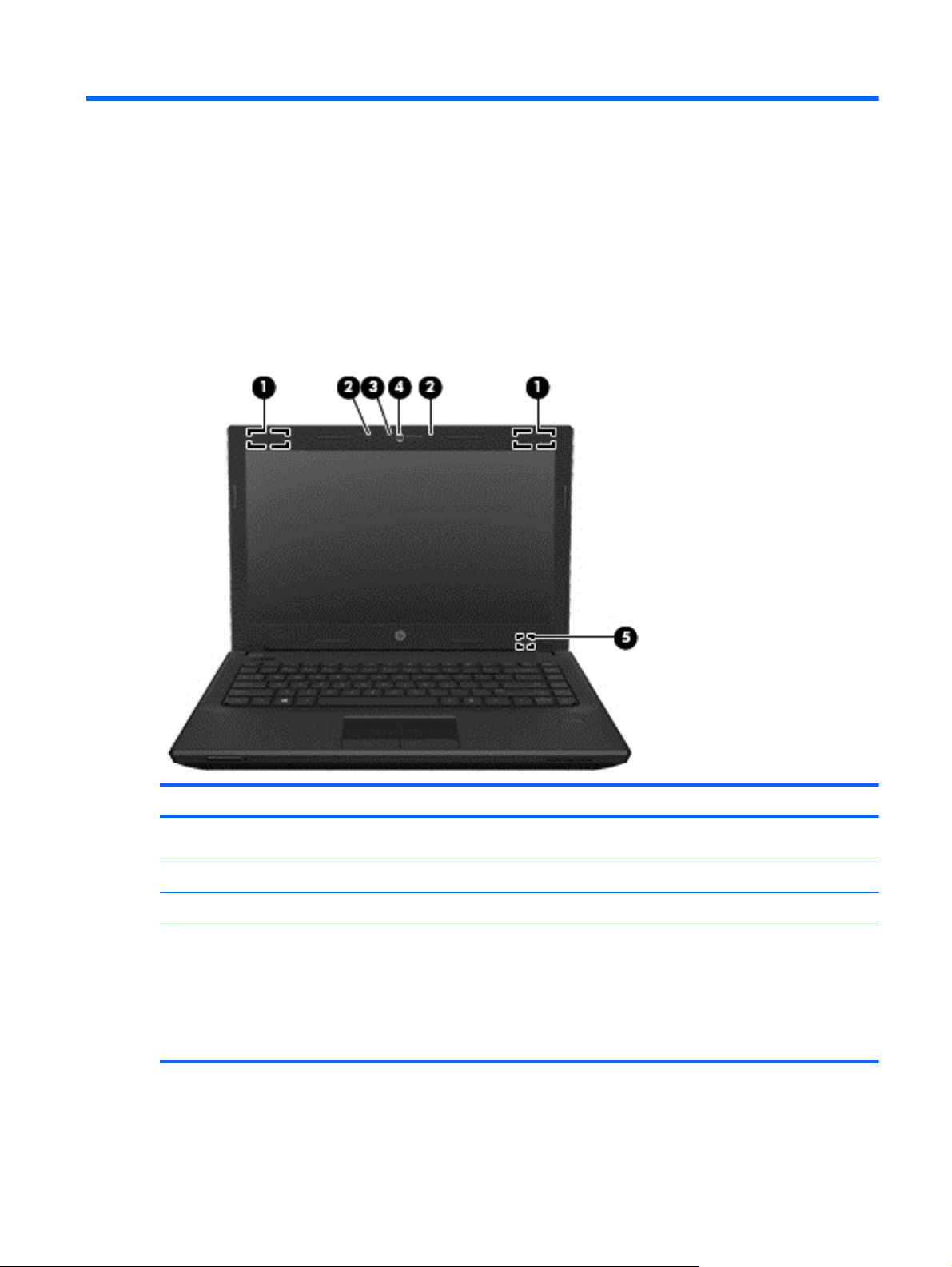
Display
Component Description
(1) WLAN antennas (2)* (select models only) Send and receive wireless signals to communicate with wireless
local area networks (WLAN).
(2) Internal microphones (2) (select models only) Record sound.
(3) Webcam light (select models only) On: The webcam is in use.
(4) Webcam (select models only) Records video and captures still photographs.
For information on using the webcam in Windows 8, access HP
Support Assistant. To access HP Support Assistant from the
Start screen, select the HP Support Assistant app.
To use the webcam in Windows 7, select Start > All Programs
> Communication and Chat > HP Webcam.
Display 5
Page 15
Component Description
(5) Internal display switch Turns off the display or initiates Sleep if the display is closed
*The antennas are not visible on the outside of the computer. For optimal transmission, keep the areas immediately around
the antennas free from obstructions. To see wireless regulatory notices, see the section of the Regulatory, Safety, and
Environmental Notices that applies to your country or region. To access the user guides in Windows 8, select the HP
Support Assistant app from the Start screen, select My computer, and then select User guides. In Windows 7, these
notices are located in Help and Support.
Top
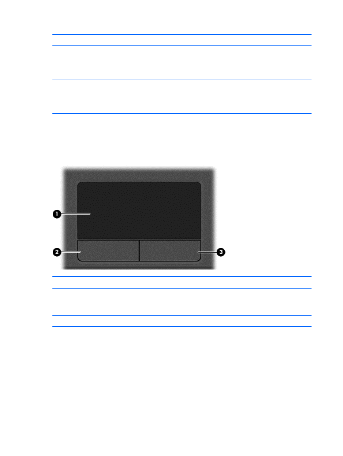
TouchPad
while the power is on.
NOTE: The display switch is not visible on the outside of the
computer.
Component Description
(1) TouchPad zone Moves the pointer and selects or activates items on the
(2) Left TouchPad button Functions like the left button on an external mouse.
(3) Right TouchPad button Functions like the right button on an external mouse.
6 Chapter 2 External component identification
screen.
Page 16
Lights
Component Description
(1)
(2)
(3) Caps lock light On: Caps lock is on.
Power light
Wireless light
White: The computer is on.
●
● Blinking white: The computer is in the Sleep state.
● Windows 8: Off: The computer is off.
Windows 7: Off: The computer is off or in Hibernation.
NOTE: For select Windows 8 models, the Intel®
Rapid Start Technology feature is enabled at the
factory. Rapid Start Technology allows your computer
to resume quickly from inactivity.
White: An integrated wireless device, such as a
●
wireless local area network (WLAN) device and/or a
Bluetooth® device, is on.
● Amber: All wireless devices are off.
Top 7
Page 17
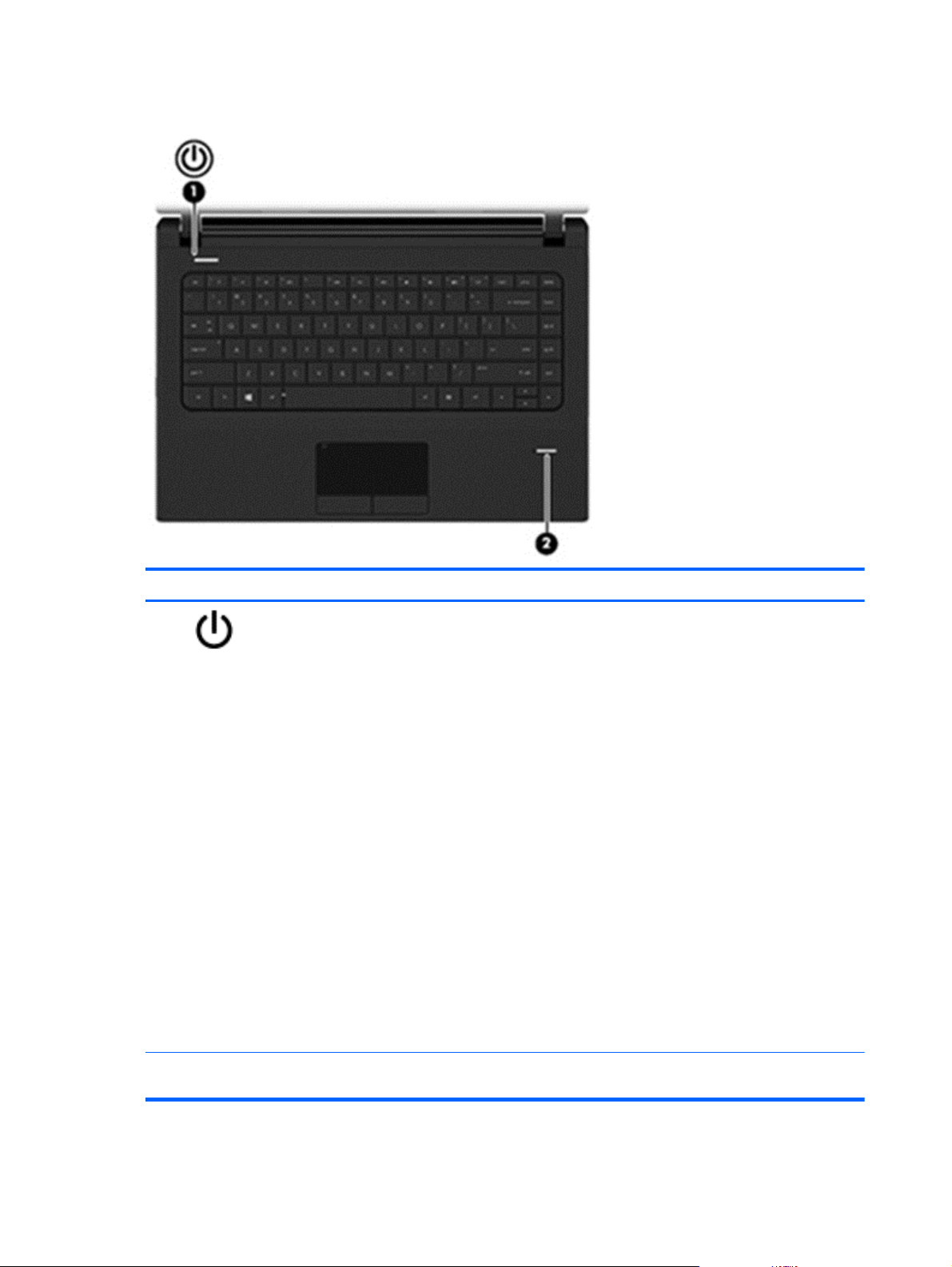
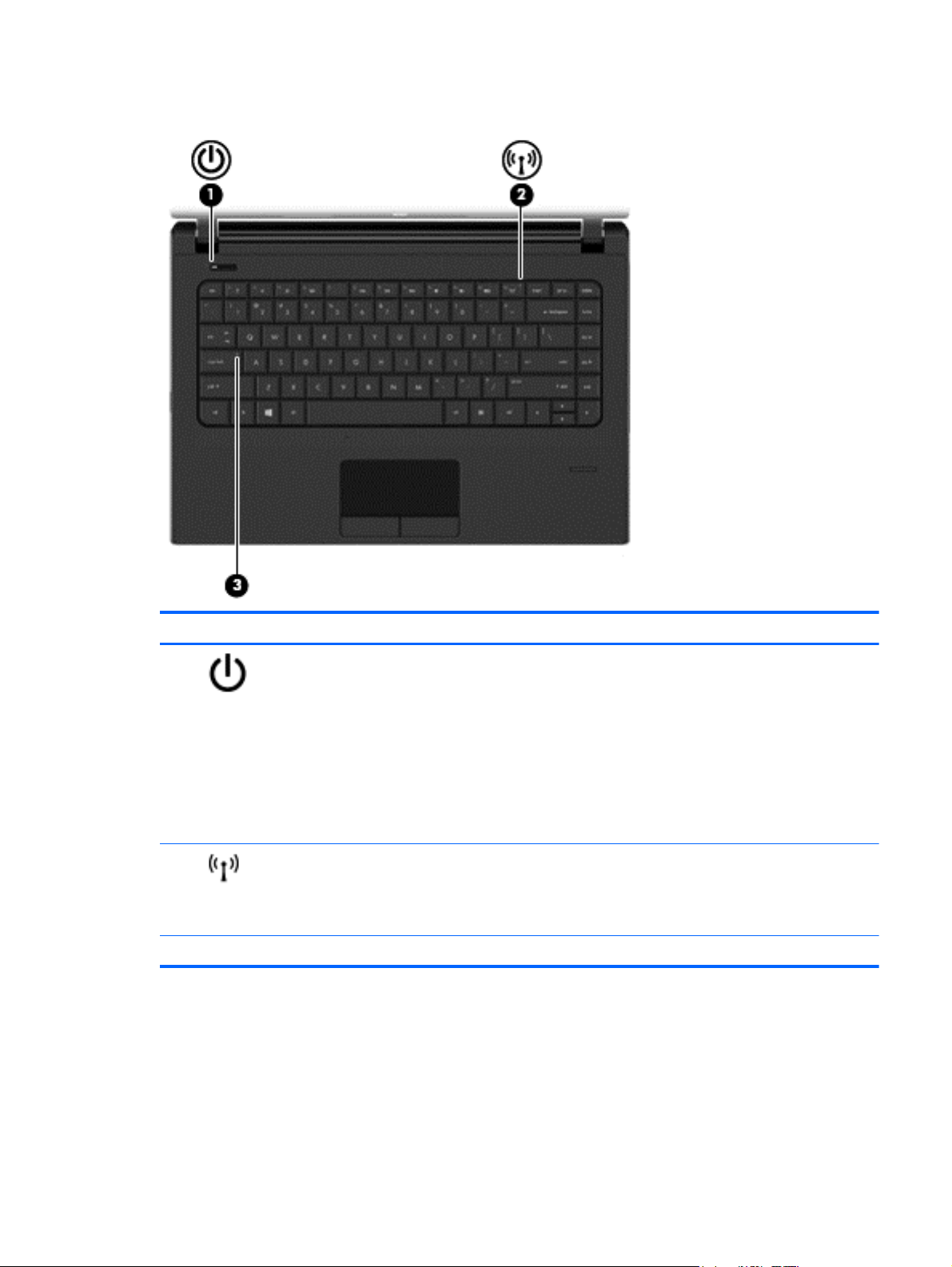
Buttons and fingerprint reader (select models only)
Component Description
(1)
Power button
When the computer is off, press the button to turn on
●
the computer.
● When the computer is in the Sleep state, press the
button briefly to exit Sleep.
When the computer is in Hibernation, press the button
●
briefly to exit Hibernation.
CAUTION: Pressing and holding down the power button
will result in the loss of unsaved information.
If the computer has stopped responding and Windows
shutdown procedures are ineffective, press and hold the
power button for at least 5 seconds to turn off the computer.
NOTE: For select Windows 8 models, the Intel® Rapid
Start Technology feature is enabled at the factory. Rapid
Start Technology allows your computer to resume quickly
from inactivity.
To learn more about your power settings in Windows 8, see
your power options. From the Start screen, type power,
select Settings, and then select Power Options.
To learn more about your power settings in Windows 7,
select Start > Control Panel > System and Security >
Power Options.
(2) Fingerprint reader (select models only) Allows a fingerprint logon to Windows, instead of a password
8 Chapter 2 External component identification
logon.
Page 18
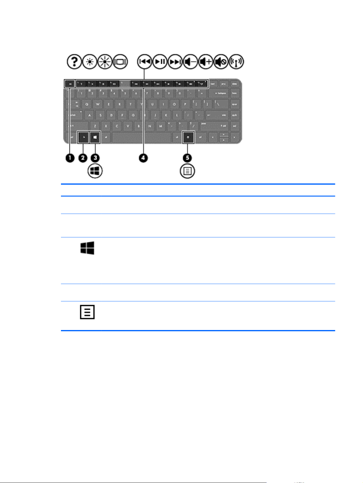
Keys
Component Description
(1) esc key Displays system information when pressed in combination
with the fn key.
(2) fn key Executes frequently used system functions when pressed
in combination with a function key, the num lk key, the esc
key, or the b key.
(3)
(4) Function keys Execute frequently used system functions when pressed in
(5)
Windows 8: Windows button
Windows 7: Windows log key
Windows applications key Windows 8: Displays options for a selected object.
Windows 8: Returns you to the Start screen from an open
app or the Windows desktop.
NOTE: Pressing the Windows button again will return you
to the previous screen.
Windows 7: Displays the Windows Start menu.
combination with the fn key.
Windows 7: Displays a shortcut menu for items beneath the
cursor.
Top 9
Page 19
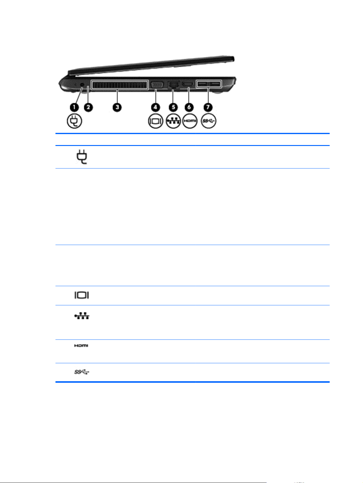
Left
Component Description
(1)
(2) AC adapter/Battery light
(3) Vent Enables airflow to cool internal components.
(4)
(5)
Power connector Connects an AC adapter.
White: The computer is connected to external power
●
and the battery is charged from 90 to 99 percent.
Amber: The computer is connected to external power
●
and the battery is charged from 0 to 89 percent.
● Blinking amber: A battery that is the only available
power source has reached a low battery level. When
the battery reaches a critical battery level, the battery
light begins blinking rapidly.
Off: The battery is fully charged.
●
NOTE: The computer fan starts up automatically to cool
internal components and prevent overheating. It is normal
for the internal fan to cycle on and off during routine
operation.
External monitor port Connects an external VGA monitor or projector.
RJ-45 (network) jack
RJ-45 (network) lights (2)
Connects a network cable.
White (left): The network is connected.
●
(6)
(7)
HDMI port Connects an optional video or audio device, such as a
USB 3.0 ports (2) Connect optional USB 3.0 devices and provide enhanced
10 Chapter 2 External component identification
Amber (right): The network is showing activity.
●
high-definition television, or any compatible digital or audio
component.
USB power performance.
Page 20
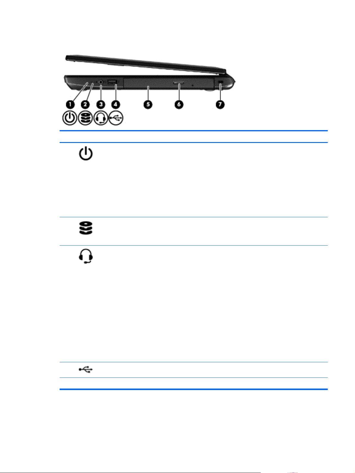
Right
Component Description
(1)
(2)
(3)
Power light
Hard drive light
Audio-out (headphone) jack/Audio-in
(microphone) jack
White: The computer is on.
●
● Blinking white: The computer is in the Sleep state.
Wiindows 8: Off: The computer is off.
●
Windows 7: Off: The computer is off or in Hibernation.
NOTE: For select Windows 8 models, the Intel®
Rapid Start Technology feature is enabled at the
factory. Rapid Start Technology allows your computer
to resume quickly from inactivity.
Blinking white: The hard drive is being accessed.
●
● Amber: HP 3D DriveGuard has temporarily parked the
hard drive.
Produces sound when connected to optional powered
stereo speakers, headphones, earbuds, a headset, or
television audio. Also connects an optional headset
microphone.
WARNING! To reduce the risk of personal injury, adjust
the volume before putting on headphones, earbuds, or a
headset. For additional safety information, see the
Regulatory, Safety, and Environmental Notices. To access
the user guides in Windows 8, select the HP Support
Assistant app from the Start screen, select My computer,
and then select User guides.
NOTE: When a device is connected to the jack, the
computer speakers are disabled.
NOTE: Be sure that the device cable has a 4-conductor
connector that supports both audio-out (headphone) and
audio-in (microphone).
(4)
(5) Optical drive (select models only) Reads and writes (select models only) to an optical disc.
USB 2.0 port Connects an optional USB device.
Right 11
Page 21
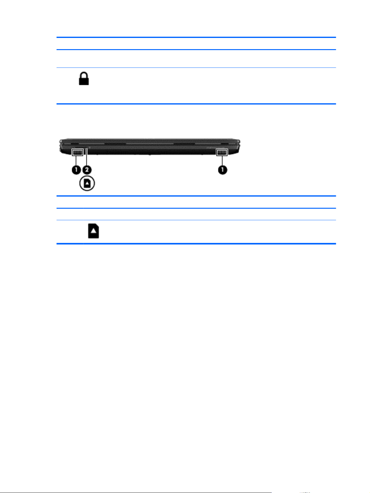
Component Description
Front
(6) Optical drive eject button (select models
(7)
Component Description
(1) Speakers (2) Produce sound.
(2)
only)
Security cable slot Attaches an optional security cable to the computer.
Media Card Reader Reads data from and writes data to digital memory
Releases the optical drive disc tray.
NOTE: The security cable is designed to act as a
deterrent, but it may not prevent the computer from being
mishandled or stolen.
cards such as Secure Digital (SD).
12 Chapter 2 External component identification
Page 22
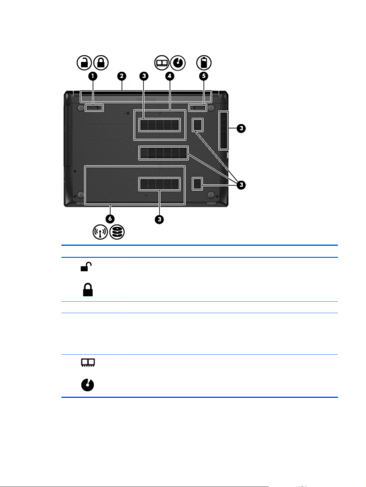
Bottom
Component Description
(1)
(2) Battery bay Holds the battery.
(3) Vents (6) Enable airflow to cool internal components.
(4)
Battery lock latch Locks the battery in the battery bay.
NOTE: The computer fan starts up automatically to
cool internal components and prevent overheating. It
is normal for the internal fan to cycle on and off during
routine operation.
Memory module service door Provides access to the memory module compartments
and the optical drive bay.
Bottom 13
Page 23

Component Description
(5)
(6)
Battery release latch Releases the battery from the battery bay.
Hard drive service door Provides access to the hard drive bay and the wireless
LAN (WLAN) module slot.
CAUTION: To prevent an unresponsive system,
replace the wireless module only with a wireless
module authorized for use in the computer by the
governmental agency that regulates wireless devices
in your country or region. If you replace the module
and then receive a warning message, remove the
module to restore computer functionality, and then
contact support through:
Windows 8: HP Support Assistant. To access HP
Support Assistant from the Start screen, select the HP
Support Assistant app.
Windows 7: Contact support through Help and
Support.
14 Chapter 2 External component identification
Page 24
3 Illustrated parts catalog
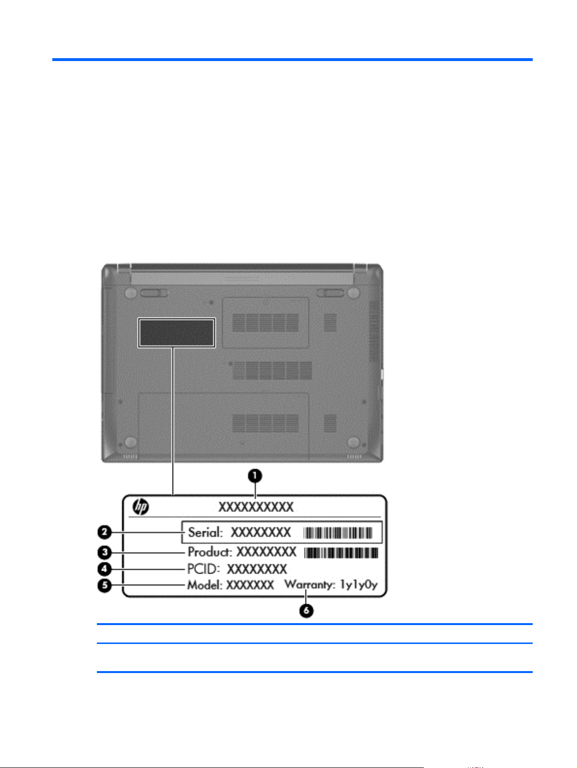
Service tag
When ordering parts or requesting information, provide the computer serial number and model
number provided on the service tag.
Item Description Function
(1) Product name This is the product name affixed to the front of
the computer.
Service tag 15
Page 25

Item Description Function
(2) Serial number (s/n) This is an alphanumeric identifier that is unique to
(3) Part number/Product number (p/n) This number provides specific information about
(4) PCID number The PCID label provides the information required to
(5) Model description This is the alphanumeric identifier used to locate
(6) Warranty period This number describes the duration of the warranty
each product.
the product's hardware components. The part
number helps a service technician to determine
what components and parts are needed.
properly reset the notebook firmware (BIOS) back to
factory shipped specifications when replacing the
system board. The label may have a different
number of characters depending on the operating
system on the computer.
documents, drivers, and support for the computer.
period for the computer.
16 Chapter 3 Illustrated parts catalog
Page 26
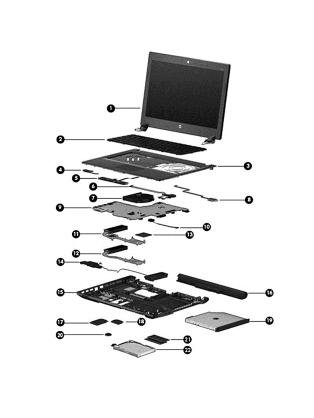
Computer major components
Computer major components 17
Page 27

Item Component Spare part number
(1) Display assembly: The display assembly is spared at the subcomponent level only. For more display assembly
spare part information, see
(2) Keyboard (includes keyboard cable):
For use in Indonesia 728127-D61
For use in Taiwan 728127-AB1
For use in Thailand 728127-281
For use in the United States 728127-001
(3) Top cover (includes TouchPad) 724300-001
(4) Power button board (includes cable) 718436-001
(5) TouchPad button board (includes bracket and cable) 728410-001
(6) Audio/USB board (includes cable) 718435-001
(7) Fan (includes cable) 718430-001
(8) Fingerprint reader board (includes bracket and cable) 725239-001
(9) System board (includes replacement thermal material):
For use in models without Windows 8 and with 2-GB of discrete graphics memory 725243-001
Display assembly subcomponents on page 20.
For use in models with Windows 8 Standard and with 2-GB of discrete graphics
memory
For use in models with Windows 8 Professional and with 2-GB of discrete graphics
memory
For use in models without Windows 8 and with 1-GB of discrete graphics memory 725242-001
For use in models with Windows 8 Standard and with 1-GB of discrete graphics
memory
For use in models with Windows 8 Professional and with 1-GB of discrete graphics
memory
For use in models without Windows 8 and with UMA graphics 725241-001
For use in models with Windows 8 Standard and with UMA graphics 725241-501
For use in models with Windows 8 Professional and with UMA graphics 725241-601
(10) Power connector cable 732625-001
Heat sink (includes replacement thermal material)
(11) For use in models with discrete graphics 718431-001
(12) For use in models with UMA graphics 728409-001
(13) Processor (includes replacement thermal material):
Intel Core i5-3230M 2.60-GHz processor (SC turbo up to 3.20-GHz; 1600-MHz FSB,
3.0-MB L3 cache, 35 W)
725243-501
725243-601
725242-501
725242-601
711903-002
Intel Core i3-3130M 2.60-GHz processor (1600-MHz FSB, 3.0-MB L3 cache, 35 W) 713163-002
Intel Core i3-3120M 2.50-GHz processor (1600-MHz FSB, 3.0-MB L3 cache, 35 W) 700627-002
Intel Core i3-2348M 2.30-GHz processor (1333-MHz FSB, 3.0-MB L3 cache, 35 W) 713165-002
18 Chapter 3 Illustrated parts catalog
Page 28

Item Component Spare part number
Intel Pentium 2020M 2.40-GHz processor (1600-MHz FSB, 2.0-MB L3 cache, 35 W) 700628-002
Intel Celeron 1020M 2.10-GHz processor (1600-MHz FSB, 2.0-MB L3 cache, 35 W) 727918-002
(14) Speakers (include left and right speakers and cables) 718443-001
(15) Base enclosure (includes 4 rubber feet, battery lock latch, and battery release latch) 724296-001
(16) Battery
4-cell, 41-Wh, 2.80-Ah, Li-ion battery 708462-001
4-cell, 48-Wh, 3.20-Ah, Li-ion battery 724933-001
(17) 32-GB mSATA drive 728857-001
(18) WLAN module:
Atheros AR9485 802.11b/g/n 1x1 WiFi Adapter 675794-001
Broadcom BCM943228 802.11abgn 2x2 Wi-Fi + Bluetooth 4.0 Combo Adapter 730668-001
Ralink RT3290LE 802.11b/g/n 1×1 WiFi and Bluetooth 4.0 Combo Adapter 690020-001
(19) DVD±RW Double-Layer with SuperMulti Drive (includes bezel and bracket) 728285-001
(20) RTC battery 718440-001
(21) Memory module (PC3L, 12800, 1600-MHz):
8-GB 693374-001
4-GB 691740-001
2-GB 691739-001
(22) Hard drive (does not include hard drive bracket or hard drive connector cable):
1-TB, 5400-rpm, 2.5-in 676521-001
750-GB, 5400-rpm, 2.5-in 634250-001
500-GB, 7200-rpm, 7.0-mm 703267-001
500-GB, 5400-rpm, 7.0-mm 683802-001
320-GB, 5400-rpm, 7.0-mm 645193-001
Hard Drive Hardware Kit (not illustrated, includes hard drive bracket and hard drive
connector cable)
718432-001
Computer major components 19
Page 29
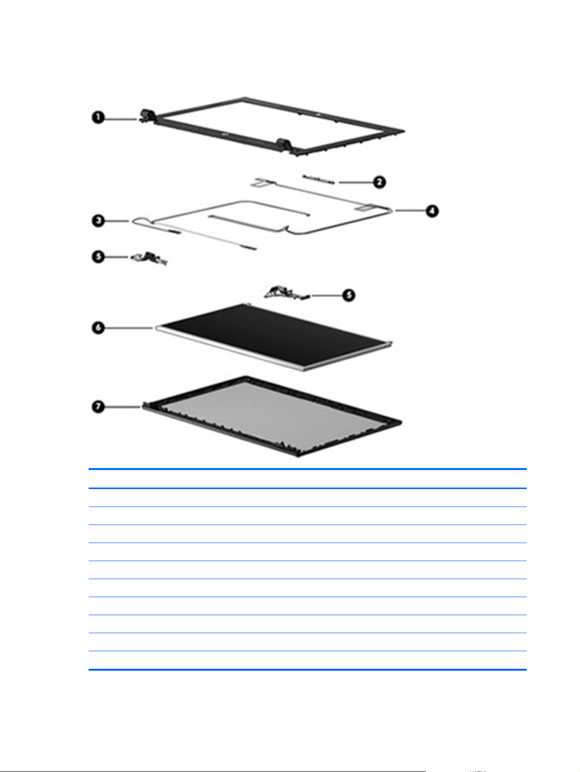
Display assembly subcomponents
Item Component Spare part number
(1) Display bezel
For use in models with a webcam 724297-001
For use in models without a webcam 728281-001
(2) Webcam/microphone module (includes double-sided adhesive) 728284-001
(3) Display panel cable (includes webcam/microphone module cable) 724298-001
(4) Antenna Kit (includes left and right wireless antenna cables and transceivers) 728280-001
(5) Display hinges 728282-001
(6) Display panel (14.0-in, anti-glare, 1366×768, HD) 725240-001
(7) Display enclosure 724295-001
Raw display panel support kit 724299-001
20 Chapter 3 Illustrated parts catalog
Page 30
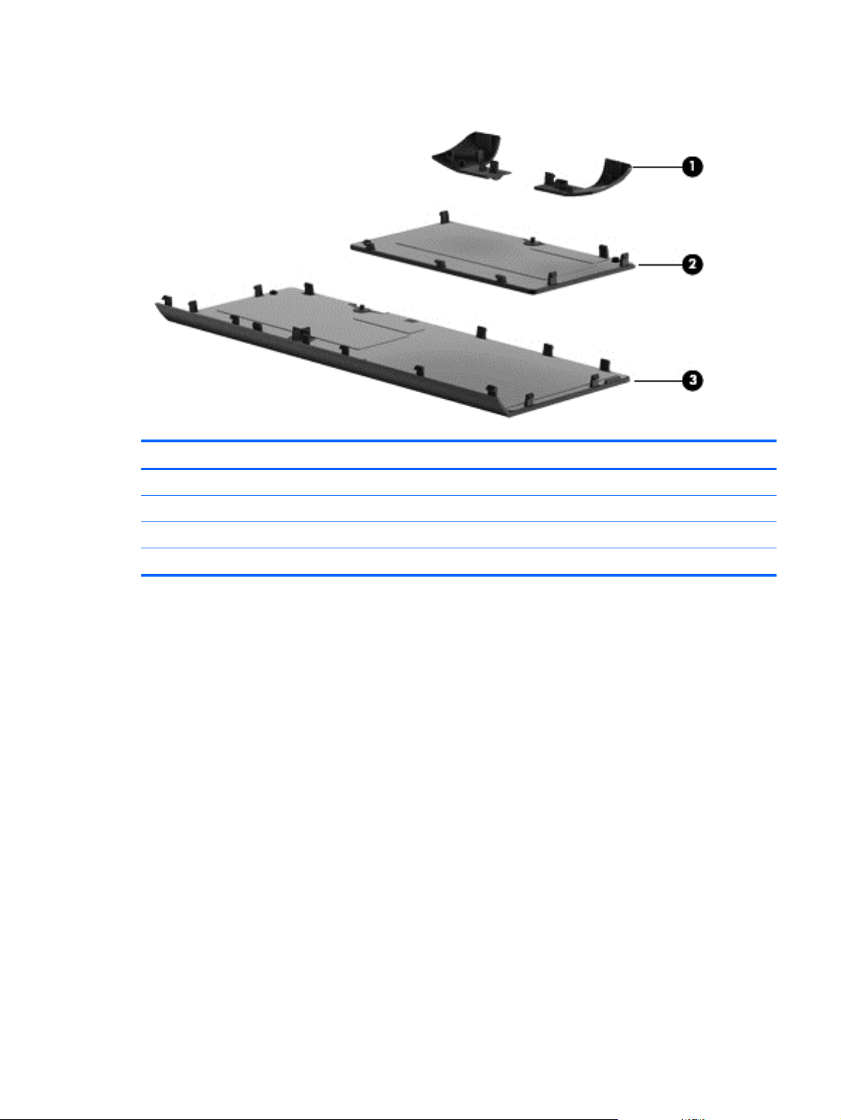
Plastics kit
Item Component Spare part number
Plastics kit 728283-001
(1) Top cover corner covers
(2) Memory cover door
(3) Hard drive cover door
Plastics kit 21
Page 31

Mass storage devices
Item Component Spare part number
(1) Hard drive (does not include hard drive bracket or hard drive connector cable):
1-TB, 5400-rpm, 2.5-in 676521-001
750-GB, 5400-rpm, 2.5-in 634250-001
500-GB, 7200-rpm, 7.0-mm 703267-001
500-GB, 5400-rpm, 7.0-mm 683802-001
320-GB, 5400-rpm, 7.0-mm 645193-001
Hard Drive Hardware Kit, includes: 718432-001
(2a) Hard drive bracket
(2b) Hard drive connector cable
(3) DVD±RW Double-Layer with SuperMulti Drive (includes bezel and bracket) 728285-001
(4) 32-GB mSATA drive 728857-001
22 Chapter 3 Illustrated parts catalog
Page 32

Miscellaneous parts
Component Spare part number
AC adapter:
90-W AC adapter for use in all countries and regions except the People’s Republic of China and
India
90-W AC adapter for use in the People’s Republic of China and India 710414-001
65-W AC adapter for use in all countries and regions except the People’s Republic of China and
India
65-W AC adapter for use in the People’s Republic of China and India 714657-001
Mouse, laser 674318-001
HP Ultraslim Keyed Cable Lock 703372-001
HP Business Case 718550-001
Power cord (3-pin, black, 1.83-m):
For use in Europe 490371-021
For use in India 490371-D61
For use in the People's Republic China 490371-AA1
For use in Taiwan 490371-AB1
For use in Thailand 490371-201
For use in the United Kingdom and Singapore 490371-031
Rubber Kit (includes rubber feet) 718441-001
710413-001
710412-001
Screw Kit 730320-001
Sequential part number listing
Spare part
number
490371-021 A Power cord for use in Europe (3-pin, black, 1.83-m)
490371-031 A Power cord for use in the United Kingdom and Singapore (3-pin, black, 1.83-m)
490371-201 A Power cord for use in Thailand (3-pin, black, 1.83-m)
490371-AA1 A Power cord for use in the People's Republic of China (3-pin, black, 1.83-m)
490371-AB1 A Power cord for use in Taiwan (3-pin, black, 1.83-m)
490371-D61 A Power cord for use in India (3-pin, black, 1.83-m)
634250-001 A 750-GB, 5400-rpm, SATA, 2.5-in hard drive (does not include hard drive bracket or hard
CSR
flag
Description
drive connector cable)
NOTE: The hard drive bracket and screws are included in the Hard Drive Hardware Kit,
spare part number 718432-001.
Miscellaneous parts 23
Page 33

Spare part
number
CSR
flag
Description
645193-001 A 320-GB, 5400-rpm, SATA, 7.0-mm hard drive (does not include hard drive bracket or hard
674318-001 A Mouse, laser
675794-001 A Atheros AR9485 802.11b/g/n 1x1 WiFi Adapter
676521-001 A 1-TB, 5400-rpm, SATA, 2.5-in hard drive (does not include hard drive bracket or hard drive
683802-001 A 500-GB, 5400-rpm, SATA, 7.0-mm hard drive (does not include hard drive bracket or hard
690020-001 A Ralink RT3290LE 802.11b/g/n 1×1 WiFi and Bluetooth 4.0 Combo Adapter
691739-001 A 2-GB memory module (PC3L, 12800, 1600-MHz)
691740-001 A 4-GB memory module (PC3L, 12800, 1600-MHz)
693374-001 A 8-GB memory module (PC3L, 12800, 1600-MHz)
700627-002 N Intel Core i3-3120M 2.50-GHz processor (1600-MHz FSB, 3.0-MB L3 cache, 35 W; includes
700628-002 N Intel Pentium 2020M 2.40-GHz processor (1600-MHz FSB, 2.0-MB L3 cache, 35 W;
drive connector cable)
connector cable)
NOTE: The hard drive bracket and screws are included in the Hard Drive Hardware Kit,
spare part number 718432-001.
drive connector cable)
NOTE: The hard drive bracket and screws are included in the Hard Drive Hardware Kit,
spare part number 718432-001.
replacement thermal material)
includes replacement thermal material)
703267-001 A 500-GB, 7200-rpm, SATA, 7.0-mm hard drive (does not include hard drive bracket or hard
drive connector cable)
703372-001 A HP Ultraslim Keyed Cable Lock
708462-001 A 4-cell, 41-Wh, 2.80-Ah, Li-ion battery
710412-001 A 65-W AC adapter for use in all countries and regions except the People’s Republic of China
710413-001 A 90-W AC adapter for use in all countries and regions except the People’s Republic of China
710414-001 A 90-W AC adapter for use in the People’s Republic of China and India
711903-002 N Intel Core i5-3230M 2.60-GHz processor (SC turbo up to 3.20-GHz; 1600-MHz FSB, 3.0-MB
713163-002 N Intel Core i5-3130M 2.60-GHz processor (1600-MHz FSB, 3.0-MB L3 cache, 35 W; includes
713165-002 N Intel Core i5-2348M 2.30-GHz processor (1333-MHz FSB, 3.0-MB L3 cache, 35 W; includes
714657-001 A 65-W AC adapter for use in the People’s Republic of China and India
718430-001 N Fan (includes cable)
718431-001 N Heat sink for use in models with discrete graphics (includes replacement thermal material)
718432-001 N Hard Drive Hardware Kit (includes hard drive bracket and hard drive connector cable)
and India
and India
L3 cache, 35 W; includes replacement thermal material)
replacement thermal material)
replacement thermal material)
24 Chapter 3 Illustrated parts catalog
Page 34

Spare part
number
718435-001 N Audio/USB board (includes cable)
718436-001 N Power button board (includes cable)
718440-001 N RTC battery
718441-001 N Rubber Kit (includes rubber feet)
718443-001 N Speakers (includes left and right speakers and cables)
718550-001 A HP Business Case
724295-001 N Display enclosure
724296-001 N Base enclosure (includes 4 rubber feet, battery lock latch, and battery release latch)
724297-001 N Display bezel for use in models with a webcam
724298-001 N Display panel cable (includes webcam/microphone module cable)
724299-001 N Raw display panel support kit
724300-001 N Top cover (includes TouchPad)
724933-001 A 4-cell, 48-Wh, 3.20-Ah, Li-ion battery
725239-001 N Fingerprint reader board (includes bracket and cable)
725240-001 N 14.0-in, anti-glare, 1366×768, HD, LED display panel
CSR
flag
Description
725241-001 N System board for use in models without Windows 8 and with UMA graphics
725241-501 N System board for use in models with Windows 8 Standard and with UMA graphics (includes
725241-601 N System board for use in models with Windows 8 Professional and with UMA graphics
725242-001 N System board for use in models without Windows 8 and with 1-GB graphics (includes
725242-501 N System board for use in models with Windows 8 Standard and with 1-GB graphics (includes
725242-601 N System board for use in models with Windows 8 Professional and with 1-GB graphics
725243-001 N System board for use in models without Windows 8 and with 2-GB of discrete graphics
725243-501 N System board for use in models with Windows 8 Standard and with 2-GB of discrete
725243-601 N System board for use in models with Windows 8 Professional and with 2-GB of discrete
727918-002 N Intel Celeron 1020M 2.10-GHz processor (1600-MHz FSB, 2.0-MB L3 cache, 35 W; includes
728127-001 B Keyboard for use in the United States (includes keyboard cable)
thermal material)
(includes thermal material)
thermal material)
thermal material)
(includes thermal material)
memory (includes thermal material)
graphics memory (includes thermal material)
graphics memory (includes thermal material)
replacement thermal material)
728127-281 B Keyboard for use in Taiwan (includes keyboard cable)
728127-AB1 B Keyboard for use in Thailand (includes keyboard cable)
728127-D61 B Keyboard for use in Indonesia (includes keyboard cable)
Sequential part number listing 25
Page 35

Spare part
number
728280-001 N Antenna Kit (includes left and right wireless antenna cables and transceivers)
728281-001 N Display bezel for use in models without a webcam
728282-001 N Display hinges (includes left and right hinges)
728283-001 A Plastics kit, includes memory cover, hard drive cover, and service cover
728284-001 N Webcam/microphone module (includes double-sided adhesive)
728285-001 A DVD±RW Double-Layer with SuperMulti Drive (includes bezel and bracket)
728409-001 N Heat sink for use in models with UMA graphics (includes replacement thermal material)
728410-001 N TouchPad button board (includes bracket and cable)
728857-001 A 32-GB mSATA drive
730320-001 N Screw Kit
730668-001 A Broadcom BCM943228 802.11abgn 2x2 Wi-Fi + Bluetooth 4.0 Combo Adapter
732625-001 N Power connector cable
CSR
flag
Description
26 Chapter 3 Illustrated parts catalog
Page 36

4 Removal and replacement procedures
preliminary requirements
Tools required
You will need the following tools to complete the removal and replacement procedures:
Flat-bladed screw driver
●
Magnetic screw driver
●
Phillips P0 and P1 screw drivers
●
Service considerations
The following sections include some of the considerations that you must keep in mind during
disassembly and assembly procedures.
NOTE: As you remove each subassembly from the computer, place the subassembly (and all
accompanying screws) away from the work area to prevent damage.
Plastic parts
CAUTION: Using excessive force during disassembly and reassembly can damage plastic parts.
Use care when handling the plastic parts. Apply pressure only at the points designated in the
maintenance instructions.
Tools required 27
Page 37

Cables and connectors
CAUTION: When servicing the computer, be sure that cables are placed in their proper locations
during the reassembly process. Improper cable placement can damage the computer.
Cables must be handled with extreme care to avoid damage. Apply only the tension required to
unseat or seat the cables during removal and insertion. Handle cables by the connector whenever
possible. In all cases, avoid bending, twisting, or tearing cables. Be sure that cables are routed in
such a way that they cannot be caught or snagged by parts being removed or replaced. Handle flex
cables with extreme care; these cables tear easily.
Drive handling
CAUTION: Drives are fragile components that must be handled with care. To prevent damage to
the computer, damage to a drive, or loss of information, observe these precautions:
Before removing or inserting a hard drive, shut down the computer. If you are unsure whether the
computer is off or in Hibernation, turn the computer on, and then shut it down through the operating
system.
Before handling a drive, be sure that you are discharged of static electricity. While handling a drive,
avoid touching the connector.
Before removing a diskette drive or optical drive, be sure that a diskette or disc is not in the drive and
be sure that the optical drive tray is closed.
Handle drives on surfaces covered with at least one inch of shock-proof foam.
Avoid dropping drives from any height onto any surface.
After removing a hard drive, an optical drive, or a diskette drive, place it in a static-proof bag.
Avoid exposing an internal hard drive to products that have magnetic fields, such as monitors or
speakers.
Avoid exposing a drive to temperature extremes or liquids.
If a drive must be mailed, place the drive in a bubble pack mailer or other suitable form of protective
packaging and label the package “FRAGILE.”
28 Chapter 4 Removal and replacement procedures preliminary requirements
Page 38

Grounding guidelines
Electrostatic discharge damage
Electronic components are sensitive to electrostatic discharge (ESD). Circuitry design and structure
determine the degree of sensitivity. Networks built into many integrated circuits provide some
protection, but in many cases, ESD contains enough power to alter device parameters or melt silicon
junctions.
A discharge of static electricity from a finger or other conductor can destroy static-sensitive devices or
microcircuitry. Even if the spark is neither felt nor heard, damage may have occurred.
An electronic device exposed to ESD may not be affected at all and can work perfectly throughout a
normal cycle. Or the device may function normally for a while, then degrade in the internal layers,
reducing its life expectancy.
CAUTION: To prevent damage to the computer when you are removing or installing internal
components, observe these precautions:
Keep components in their electrostatic-safe containers until you are ready to install them.
Before touching an electronic component, discharge static electricity by using the guidelines
described in this section.
Avoid touching pins, leads, and circuitry. Handle electronic components as little as possible.
If you remove a component, place it in an electrostatic-safe container.
The following table shows how humidity affects the electrostatic voltage levels generated by different
activities.
CAUTION: A product can be degraded by as little as 700 V.
Typical electrostatic voltage levels
Relative humidity
Event 10% 40% 55%
Walking across carpet 35,000 V 15,000 V 7,500 V
Walking across vinyl floor 12,000 V 5,000 V 3,000 V
Motions of bench worker 6,000 V 800 V 400 V
Removing DIPS from plastic tube 2,000 V 700 V 400 V
Removing DIPS from vinyl tray 11,500 V 4,000 V 2,000 V
Removing DIPS from Styrofoam 14,500 V 5,000 V 3,500 V
Removing bubble pack from PCB 26,500 V 20,000 V 7,000 V
Packing PCBs in foam-lined box 21,000 V 11,000 V 5,000 V
Grounding guidelines 29
Page 39

Packaging and transporting guidelines
Follow these grounding guidelines when packaging and transporting equipment:
To avoid hand contact, transport products in static-safe tubes, bags, or boxes.
●
Protect ESD-sensitive parts and assemblies with conductive or approved containers or
●
packaging.
Keep ESD-sensitive parts in their containers until the parts arrive at static-free workstations.
●
Place items on a grounded surface before removing items from their containers.
●
Always be properly grounded when touching a component or assembly.
●
Store reusable ESD-sensitive parts from assemblies in protective packaging or nonconductive
●
foam.
Use transporters and conveyors made of antistatic belts and roller bushings. Be sure that
●
mechanized equipment used for moving materials is wired to ground and that proper materials
are selected to avoid static charging. When grounding is not possible, use an ionizer to dissipate
electric charges.
Workstation guidelines
Follow these grounding workstation guidelines:
Cover the workstation with approved static-shielding material.
●
Use a wrist strap connected to a properly grounded work surface and use properly grounded
●
tools and equipment.
Use conductive field service tools, such as cutters, screw drivers, and vacuums.
●
When fixtures must directly contact dissipative surfaces, use fixtures made only of static-safe
●
materials.
Keep the work area free of nonconductive materials, such as ordinary plastic assembly aids and
●
Styrofoam.
Handle ESD-sensitive components, parts, and assemblies by the case or PCM laminate. Handle
●
these items only at static-free workstations.
Avoid contact with pins, leads, or circuitry.
●
Turn off power and input signals before inserting or removing connectors or test equipment.
●
30 Chapter 4 Removal and replacement procedures preliminary requirements
Page 40

Equipment guidelines
Grounding equipment must include either a wrist strap or a foot strap at a grounded workstation.
● When seated, wear a wrist strap connected to a grounded system. Wrist straps are flexible
straps with a minimum of one megohm ±10% resistance in the ground cords. To provide proper
ground, wear a strap snugly against the skin at all times. On grounded mats with banana-plug
connectors, use alligator clips to connect a wrist strap.
When standing, use foot straps and a grounded floor mat. Foot straps (heel, toe, or boot straps)
●
can be used at standing workstations and are compatible with most types of shoes or boots. On
conductive floors or dissipative floor mats, use foot straps on both feet with a minimum of one
megohm resistance between the operator and ground. To be effective, the conductive must be
worn in contact with the skin.
The following grounding equipment is recommended to prevent electrostatic damage:
Antistatic tape
●
Antistatic smocks, aprons, and sleeve protectors
●
Conductive bins and other assembly or soldering aids
●
Nonconductive foam
●
● Conductive tabletop workstations with ground cords of one megohm resistance
● Static-dissipative tables or floor mats with hard ties to the ground
Field service kits
●
Static awareness labels
●
Material-handling packages
●
Nonconductive plastic bags, tubes, or boxes
●
● Metal tote boxes
● Electrostatic voltage levels and protective materials
The following table lists the shielding protection provided by antistatic bags and floor mats.
Material Use Voltage protection level
Antistatic plastics Bags 1,500 V
Carbon-loaded plastic Floor mats 7,500 V
Metallized laminate Floor mats 5,000 V
Grounding guidelines 31
Page 41

5 Removal and replacement procedures
for Customer Self-Repair parts
NOTE: The Customer Self-Repair program is not available in all locations. Installing a part not
supported by the Customer Self-Repair program may void your warranty. Check your warranty to
determine if Customer Self-Repair is supported in your location.
Component replacement procedures
NOTE: Please read and follow the procedures described here to access and replace Customer
Self-Repair parts successfully.
NOTE: Details about your computer, including model, serial number, product key, and length of
warranty, are on the service tag at the bottom of your computer. See Service tag on page 16 for
details.
This chapter provides removal and replacement procedures for Customer Self-Repair parts.
There are as many as 6 screws that must be removed, replaced, and/or loosened when servicing
Customer Self-Repair parts. Make special note of each screw size and location during removal and
replacement.
32 Chapter 5 Removal and replacement procedures for Customer Self-Repair parts
Page 42

Battery
Description Spare part number
4-cell, 41-Wh, 2.80-Ah, Li-ion battery 708462-001
4-cell, 48-Wh, 3.20-Ah, Li-ion battery 724933-001
Before removing the battery, follow these steps:
1. Turn off the computer. If you are unsure whether the computer is off or in Hibernation, turn the
computer on, and then shut it down through the operating system.
2. Disconnect the power from the computer by unplugging the power cord from the computer.
3. Disconnect all external devices from the computer.
Remove the battery:
WARNING! To reduce potential safety issues, use only the user-replaceable battery provided with
the computer, a replacement battery provided by HP, or a compatible battery purchased from HP.
CAUTION: Removing a user-replaceable battery that is the sole power source for the computer can
cause loss of information. To prevent loss of information, save your work or shut down the computer
through Windows before removing the battery.
1. Turn the computer upside down, with the rear toward you.
2. Place the computer on a flat surface, free of obstacles, with ample work space.
3. Slide the battery lock latch (1), and then slide the battery release latch (2) to release the battery.
4. Remove the battery (3) from the computer.
Reverse this procedure to install the battery.
Component replacement procedures 33
Page 43

Hard drive
NOTE: The hard drive spare part kit does not include the hard drive bracket or hard drive connector
cable. These components are included in the Hard Drive Hardware Kit, spare part number
718432-001.
Description Spare part number
1-TB, 5400-rpm, 2.5-in 676521-001
750-GB, 5400-rpm, 2.5-in 634250-001
500-GB, 7200-rpm, 7.0-mm 703267-001
500-GB, 5400-rpm, 7.0-mm 683802-001
320-GB, 5400-rpm, 7.0-mm 645193-001
Before removing the hard drive, follow these steps:
1. Turn off the computer. If you are unsure whether the computer is off or in Hibernation, turn the
2. Disconnect the power from the computer by unplugging the power cord from the computer.
3. Disconnect all external devices from the computer.
computer on, and then shut it down through the operating system.
4. Remove the battery (see
Battery on page 33).
Remove the hard drive:
1. Loosen the Phillips PM2.5×4.5 captive screw (1) that secures the hard drive service cover to the
computer.
2. Lift the rear edge of the hard drive service cover (2) and swing it up and forward until it
disengages from the computer.
34 Chapter 5 Removal and replacement procedures for Customer Self-Repair parts
Page 44

3. Remove the hard drive service cover. The hard drive service cover is included in the Plastics Kit,
spare part number 718432-001.
4. Disconnect the hard drive connector cable (1) from the system board.
5. Lift the hard drive to remove it from the hard drive bay (2).
6. If it is necessary to disassemble the hard drive, perform the following steps:
a. Position the hard drive with the connector toward you.
b. Disconnect the hard drive connector cable (1) from the hard drive.
c. Spread the left and right sides (2) of the hard drive bracket outward to separate the bracket
from the hard drive.
d. Remove the hard drive bracket (3) from the hard drive.
The hard drive bracket and hard drive connector cable are available in the Hard Drive
Hardware Kit, spare part number 718432-001.
Component replacement procedures 35
Page 45

Reverse this procedure to reassemble and install the hard drive.
36 Chapter 5 Removal and replacement procedures for Customer Self-Repair parts
Page 46

WLAN module
Description Spare part number
Atheros AR9485 802.11b/g/n 1x1 WiFi Adapter 675794-001
Broadcom BCM943228 802.11abgn 2x2 Wi-Fi + Bluetooth 4.0 Combo Adapter 730668-001
Ralink RT3290LE 802.11b/g/n 1×1 WiFi and Bluetooth 4.0 Combo Adapter 690020-001
CAUTION: To prevent an unresponsive system, replace the wireless module only with a wireless
module authorized for use in the computer by the governmental agency that regulates wireless
devices in your country or region. If you replace the module and then receive a warning message,
remove the module to restore device functionality, and then contact technical support.
Before removing the WLAN module, follow these steps:
1. Turn off the computer. If you are unsure whether the computer is off or in Hibernation, turn the
computer on, and then shut it down through the operating system.
2. Disconnect the power from the computer by unplugging the power cord from the computer.
3. Disconnect all external devices from the computer.
4. Remove the battery (see
5. Remove the hard drive service cover (see
Battery on page 33).
Hard drive on page 34).
Remove the WLAN module:
1. Disconnect the WLAN antenna cables (1) from the terminals on the WLAN module.
NOTE: The WLAN antenna cable labeled “1” connects to the WLAN module “Main” terminal
labeled “1”. The WLAN antenna cable labeled “2” connects to the WLAN module “Aux” terminal
labeled “2”.
2. Remove the two Phillips PM2.0×2.0 screws (2) that secure the WLAN module to the system
board. (The WLAN module tilts up.)
Component replacement procedures 37
Page 47

3. Remove the WLAN module (3) by pulling the module away from the slot at an angle.
NOTE: If the WLAN antenna cables are not connected to the terminals on the WLAN module, the
protective sleeves must be installed on the antenna connectors, as shown in the following illustration.
Reverse this procedure to install the WLAN module.
38 Chapter 5 Removal and replacement procedures for Customer Self-Repair parts
Page 48

mSATA drive
Description Spare part number
32-GB mSATA drive 728857-001
Before removing the mSATA drive, follow these steps:
1. Turn off the computer. If you are unsure whether the computer is off or in Hibernation, turn the
computer on, and then shut it down through the operating system.
2. Disconnect the power from the computer by unplugging the power cord from the computer.
3. Disconnect all external devices from the computer.
4. Remove the battery (see
5. Remove the hard drive service cover (see
Battery on page 33).
Hard drive on page 34).
Remove the mSATA drive:
1. Remove the Phillips PM2.0×2.0 screw (1) that secures the mSATA drive to the system board.
(The mSATA drive tilts up.)
2. Remove the mSATA drive (2) by pulling the module away from the slot at an angle.
Reverse this procedure to install the mSATA drive.
Component replacement procedures 39
Page 49

Memory module
Description Spare part number
8-GB (PC3L, 12800, 1600-MHz) 693374-001
4-GB (PC3L, 12800, 1600-MHz) 691740-001
2-GB (PC3L, 12800, 1600-MHz) 691739-001
Update BIOS before adding memory modules
Before adding new memory, make sure you update the computer to the latest BIOS.
CAUTION: Failure to update the computer to the latest BIOS prior to installing new memory may
result in various system problems.
To update BIOS:
1. Navigate to
www.hp.com.
2. Click Support & Drivers > click Drivers & Software.
3. In the Enter a product name/number box, type the computer model information, and then click
Search.
4. Click the link for the computer model.
5. Select the operating system, and then click Next.
6. Under Step 2: Select a Download, click the BIOS link.
7. Click the link for the most recent BIOS.
8. Click the Download button, and then follow the on-screen instructions.
Before removing a memory module, follow these steps:
1. Turn off the computer. If you are unsure whether the computer is off or in Hibernation, turn the
computer on, and then shut it down through the operating system.
2. Disconnect the power from the computer by unplugging the power cord from the computer.
3. Disconnect all external devices from the computer.
4. Remove the battery (see
Battery on page 33).
Remove the memory module:
1. Loosen the Phillips PM2.5×4.5 captive screw (1) that secures the memory module service cover
to the computer.
40 Chapter 5 Removal and replacement procedures for Customer Self-Repair parts
Page 50

2. Lift the rear edge of the memory module service cover (2) and swing it up and forward until it
disengages from the computer.
3. Remove the memory module service cover.
The memory module service cover is included in the Plastics Kit, spare part number
728283-001.
4. Spread the retaining tabs (1) on each side of the memory module slot to release the memory
module. (The memory module tilts up.)
5. Remove the memory module (2) by pulling the module away from the slot at an angle.
Reverse this procedure to install a memory module.
Component replacement procedures 41
Page 51

Optical drive
All optical drive spare part kits contain a bezel and bracket.
Description Spare part number
DVD±RW Double-Layer with SuperMulti Drive 728285-001
Before removing the optical drive, follow these steps:
1. Turn off the computer. If you are unsure whether the computer is off or in Hibernation, turn the
computer on, and then shut it down through the operating system.
2. Disconnect the power from the computer by unplugging the power cord from the computer.
3. Disconnect all external devices from the computer.
4. Remove the battery (see
5. Remove the memory module service cover (see
Battery on page 33).
Memory module on page 40).
Remove the optical drive:
1. Remove the Phillips PM2.5×4.5 screw (1) that secures the optical drive to the computer.
2. Push the optical drive tab (2) to release the optical drive from the computer.
42 Chapter 5 Removal and replacement procedures for Customer Self-Repair parts
Page 52

3. Remove the optical drive (3).
4. If it is necessary to replace the optical drive bracket, position the optical drive with the rear
toward you.
5. Remove the two Phillips PM2.0×3.0 screws (1) that secure the optical drive bracket to the optical
drive.
Component replacement procedures 43
Page 53

6. Remove the optical drive bracket (2).
Reverse this procedure to install the optical drive.
44 Chapter 5 Removal and replacement procedures for Customer Self-Repair parts
Page 54

RTC battery
Description Spare part number
RTC battery 718440-001
Before removing the RTC battery, follow these steps:
1. Turn off the computer. If you are unsure whether the computer is off or in Hibernation, turn the
computer on, and then shut it down through the operating system.
2. Disconnect the power from the computer by unplugging the power cord from the computer.
3. Disconnect all external devices from the computer.
4. Remove the battery (see
5. Remove the hard drive service cover (see
Battery on page 33).
Hard drive on page 34).
Remove the RTC battery:
1. Use a thin screwdriver or similar tool to pry the battery out of the socket (1).
2. Remove the RTC battery from the socket (2).
Reverse this procedure to install the RTC battery. When installing the RTC battery, make sure the “+”
sign faces up.
Component replacement procedures 45
Page 55

6 Removal and replacement procedures
for Authorized Service Provider parts
CAUTION: Components described in this chapter should only be accessed by an authorized
service provider. Accessing these parts can damage the computer or void the warranty.
Component replacement procedures
NOTE: Details about your computer, including model, serial number, product key, and length of
warranty, are on the service tag at the bottom of your computer. See
details.
This chapter provides removal and replacement procedures for Authorized Service Provider only
parts.
Service tag on page 15 for
There are as many as 47 screws that must be removed, replaced, and/or loosened when servicing
Authorized Service Provider only parts. Make special note of each screw size and location during
removal and replacement.
46 Chapter 6 Removal and replacement procedures for Authorized Service Provider parts
Page 56

Keyboard
NOTE: The keyboard spare part kit includes a keyboard cable.
For use in country/region Spare part number
For use in Indonesia 728127-D61
For use in Taiwan 728127-AB1
For use in Thailand 728127-281
For use in the United States 728127-001
Before removing the keyboard, follow these steps:
1. Turn off the computer. If you are unsure whether the computer is off or in Hibernation, turn the
2. Disconnect the power from the computer by unplugging the power cord from the computer.
3. Disconnect all external devices from the computer.
computer on, and then shut it down through the operating system.
4. Remove the battery (see
5. Remove the memory module service cover (see
Battery on page 33).
Memory module on page 40).
Remove the keyboard:
1. Remove the three Phillips PM2.5×6.5 screws that secure the keyboard to the computer.
2. Rest and secure the computer on its left side.
3. Partially open the computer.
Component replacement procedures 47
Page 57

4. Insert a thin tool into the keyboard release hole in the memory module compartment, and then
press on the back of the keyboard until the keyboard disengages from the computer.
5. Turn the computer right-side up with the front toward you.
6. Lift the rear edge of the keyboard, and then swing the keyboard up and forward until it rests
upside down on the palm rest.
7. Release the zero insertion force (ZIF) connector (1) to which the keyboard cable is attached, and
then disconnect the keyboard cable (2) from the system board.
48 Chapter 6 Removal and replacement procedures for Authorized Service Provider parts
Page 58

8. Remove the keyboard (3).
Reverse this procedure to install the keyboard.
Component replacement procedures 49
Page 59

Top cover
Description Spare part number
Top cover (includes TouchPad) 724300-001
Before removing the top cover, follow these steps:
1. Turn off the computer. If you are unsure whether the computer is off or in Hibernation, turn the
2. Disconnect the power from the computer by unplugging the power cord from the computer.
3. Disconnect all external devices from the computer.
computer on, and then shut it down through the operating system.
4. Remove the battery (see
a. Hard drive (see
b. Memory module service cover (see
c. Optical drive (see
d. Keyboard (see
When replacing the top cover, be sure that the power button board (see
Battery on page 33) and then remove the following components:
Hard drive on page 34)
Memory module on page 40)
Optical drive on page 42)
Keyboard on page 47)
Power button board
on page 54) and TouchPad button board (see TouchPad button board on page 55) are removed
from the defective top cover and installed on the replacement top cover.
Remove the top cover:
1. Remove the rear corner covers (1).
2. Remove the six Phillips PM2.5×6.5 screws (2) that secure the top cover to the computer.
3. Remove the five Phillips PM2.5×4.0 screws (1) that secure the top cover to the computer.
50 Chapter 6 Removal and replacement procedures for Authorized Service Provider parts
Page 60

4. Remove the two Phillips PM2.0×2.0 broad head screws (2) in the optical drive bay that secure
the top cover to the computer.
5. Turn the computer upright with the front toward you and open it.
6. Release the following ZIF connectors on the system board:
(1): Power button board cable
●
(2): TouchPad button board cable
●
(3): Fingerprint board cable
●
7. Lift the rear edge of the top cover (1) and swing it up and forward until it detaches from the
computer.
Component replacement procedures 51
Page 61

8. Remove the top cover (2).
Reverse this procedure to install the top cover.
Fingerprint reader board
Description Spare part number
Fingerprint reader board (includes bracket and cable) 725239-001
Before removing the power button board, follow these steps:
1. Turn off the computer. If you are unsure whether the computer is off or in Hibernation, turn the
computer on, and then shut it down through the operating system.
2. Disconnect the power from the computer by unplugging the power cord from the computer.
3. Disconnect all external devices from the computer.
4. Remove the battery (see
a. Hard drive (see
b. Memory module service cover (see
c. Optical drive (see
d. Keyboard (see
e. Top cover (see
Battery on page 33) and then remove the following components:
Hard drive on page 34)
Memory module on page 40)
Optical drive on page 42)
Keyboard on page 47)
Top cover on page 50)
Remove the fingerprint reader board:
1. Disconnect the fingerprint reader ribbon cable from the board (1).
2. Remove the Phillips PM2.0×4.0 screw (2) that secures the fingerprint reader bracket to the top
cover.
52 Chapter 6 Removal and replacement procedures for Authorized Service Provider parts
Page 62

3. Lift the fingerprint reader bracket up off of its alignment pins and out of its slot in the top cover
(3).
4. The fingerprint reader is held in place with double-sided adhesive. Carefully pry the fingerprint
reader up off of the top cover (4).
Reverse this procedure to install the fingerprint reader board.
Component replacement procedures 53
Page 63

Power button board
Description Spare part number
Power button board (includes cable) 718436-001
Before removing the power button board, follow these steps:
1. Turn off the computer. If you are unsure whether the computer is off or in Hibernation, turn the
computer on, and then shut it down through the operating system.
2. Disconnect the power from the computer by unplugging the power cord from the computer.
3. Disconnect all external devices from the computer.
4. Remove the battery (see
a. Hard drive (see
b. Memory module service cover (see
c. Optical drive (see
d. Keyboard (see
e. Top cover (see
Battery on page 33) and then remove the following components:
Hard drive on page 34)
Memory module on page 40)
Optical drive on page 42)
Keyboard on page 47)
Top cover on page 50)
Remove the power button board:
1. Detach the power button board cable (1) from the top cover. (The power button board cable is
attached to the top cover with double-sided tape.)
2. Remove the Phillips PM2.5×4.0 screw (2) that secures the power button board to the top cover.
3. Lift the left side of the power button board (3) until it rests at an angle, and then remove the
power button board by sliding it up and to the left (4).
Reverse this procedure to install the power button board.
54 Chapter 6 Removal and replacement procedures for Authorized Service Provider parts
Page 64

TouchPad button board
Description Spare part number
TouchPad button board (includes bracket and cable) 728410-001
Before removing the TouchPad button board, follow these steps:
1. Turn off the computer. If you are unsure whether the computer is off or in Hibernation, turn the
computer on, and then shut it down through the operating system.
2. Disconnect the power from the computer by unplugging the power cord from the computer.
3. Disconnect all external devices from the computer.
4. Remove the battery (see
a. Hard drive (see
b. Memory module service cover (see
c. Optical drive (see
d. Keyboard (see
e. Top cover (see
Battery on page 33) and then remove the following components:
Hard drive on page 34)
Memory module on page 40)
Optical drive on page 42)
Keyboard on page 47)
Top cover on page 50)
Remove the TouchPad button board:
1. Detach the TouchPad button board cable (1) from the TouchPad. (The TouchPad button board
cable is attached to the TouchPad with double-sided tape.)
2. Release the ZIF connector (2) to which the TouchPad cable is attached, and then disconnect the
TouchPad cable from the TouchPad board.
3. Remove the two Phillips PM2.5×4.0 screws (3) that secure the TouchPad button board to the
top cover.
4. Remove the TouchPad button board bracket (4).
Component replacement procedures 55
Page 65

5. Remove the TouchPad button board (5).
Reverse this procedure to install the TouchPad button board.
56 Chapter 6 Removal and replacement procedures for Authorized Service Provider parts
Page 66

Fan
Description Spare part number
Fan (includes cable) 718430-001
Before removing the fan, follow these steps:
1. Turn off the computer. If you are unsure whether the computer is off or in Hibernation, turn the
computer on, and then shut it down through the operating system.
2. Disconnect the power from the computer by unplugging the power cord from the computer.
3. Disconnect all external devices from the computer.
4. Remove the battery (see
a. Hard drive (see
b. Memory module service cover (see
c. Optical drive (see
d. Keyboard (see
e. Top cover (see
Battery on page 33) and then remove the following components:
Hard drive on page 34)
Memory module on page 40)
Optical drive on page 42)
Keyboard on page 47)
Top cover on page 50)
Remove the fan:
1. Close the computer.
2. Turn the computer upside down, with the front toward you.
3. Disconnect the fan cable from the system board.
Component replacement procedures 57
Page 67

4. Turn the computer right side up, with the front toward you.
5. Open the computer.
6. Remove the tape (1) that attaches the fan to the heat sink.
7. Remove the two Phillips PM2.0×4.5 screws (2) that secure the fan to the base enclosure.
8. Remove the fan (3) from the base enclosure.
Reverse this procedure to install the fan.
58 Chapter 6 Removal and replacement procedures for Authorized Service Provider parts
Page 68

Audio/USB board
Description Spare part number
Audio/USB board (includes cable) 718435-001
Before removing the audio/USB board, follow these steps:
1. Turn off the computer. If you are unsure whether the computer is off or in Hibernation, turn the
computer on, and then shut it down through the operating system.
2. Disconnect the power from the computer by unplugging the power cord from the computer.
3. Disconnect all external devices from the computer.
4. Remove the battery (see
a. Hard drive (see
b. Memory module service cover (see
c. Optical drive (see
d. Keyboard (see
e. Top cover (see
Battery on page 33) and then remove the following components:
Hard drive on page 34)
Memory module on page 40)
Optical drive on page 42)
Keyboard on page 47)
Top cover on page 50)
Remove the audio/USB board:
1. Release the ZIF connector (1) to which the audio/USB board cable is attached, and then
disconnect the audio/USB board cable from the system board.
2. Detach the audio/USB board cable (2) from the base enclosure. (The audio/USB board cable is
attached to the base enclosure with double-sided tape.)
3. Remove the Phillips PM2.5×4.0 screw (3) that secures the audio/USB board to the base
enclosure.
Component replacement procedures 59
Page 69

4. Remove the audio/USB (4) from the base enclosure.
Reverse this procedure to install the audio/USB board.
60 Chapter 6 Removal and replacement procedures for Authorized Service Provider parts
Page 70

System board
NOTE: The system board spare part kit includes replacement thermal material.
Description Spare part number
System board for use in models without Windows 8 and with 2-GB of discrete graphics memory 725243-001
System board for use in models with Windows 8 Standard and with 2-GB of discrete graphics
memory
System board for use in models with Windows 8 Professional and with 2-GB of discrete graphics
memory
System board for use in models without Windows 8 and with 1-GB of discrete graphics memory 725242-001
System board for use in models with Windows 8 Standard and with 1-GB of discrete graphics
memory
System board for use in models with Windows 8 Professional and with 1-GB of discrete graphics
memory
System board for use in models without Windows 8 and with UMA graphics 725241-001
System board for use in models with Windows 8 Standard and with UMA graphics 725241-501
System board for use in models with Windows 8 Professional and with UMA graphics 725241-601
725243-501
725243-601
725242-501
725242-601
Before removing the system board, follow these steps:
1. Turn off the computer. If you are unsure whether the computer is off or in Hibernation, turn the
computer on, and then shut it down through the operating system.
2. Disconnect the power from the computer by unplugging the power cord from the computer.
3. Disconnect all external devices from the computer.
4. Remove the battery (see
a. Hard drive (see
b. WLAN module (see
c. Solid-state drive (see
Battery on page 33) and then remove the following components:
Hard drive on page 34)
WLAN module on page 37)
mSATA drive on page 39)
d. Memory module service cover (see
e. Optical drive (see
f. Keyboard (see
g. Top cover (see
h. Fan (see
Fan on page 57)
Optical drive on page 42)
Keyboard on page 47)
Top cover on page 50)
Memory module on page 40)
Component replacement procedures 61
Page 71

NOTE: When replacing the system board, be sure that the following components are removed from
the defective system board and installed on the replacement system board:
Memory module (see
●
Heat sink (see
●
Processor (see
●
Remove the system board:
1. Close the computer.
2. Turn the computer upside down, with the front toward you.
3. Disconnect the display panel cable from the system board.
Memory module on page 40)
Heat sink on page 65)
Processor on page 68)
4. Turn the computer right side up, with the front toward you.
5. Open the computer.
6. Disconnect the speaker cable (1) from the system board.
62 Chapter 6 Removal and replacement procedures for Authorized Service Provider parts
Page 72

7. Release the ZIF connector (2) to which the audio/USB board cable is attached, and then
disconnect the audio/USB board cable from the system board.
8. Release the power connector (1) from the clips and molding built into the base enclosure.
9. Release the power connector cable (2) from the routing channel built into the base enclosure.
10. Remove the three Phillips PM2.5×4.5 screws (3) that secure the system board to the base
enclosure.
11. Lift the right side of the system board (1) until it rests at an angle.
Component replacement procedures 63
Page 73

12. Remove the system board by sliding it up and to the right an angle (2).
Reverse this procedure to install the system board.
Power connector cable
Description Spare part number
Power connector cable 732625-001
Before removing the power connector cable, follow these steps:
1. Turn off the computer. If you are unsure whether the computer is off or in Hibernation, turn the
computer on, and then shut it down through the operating system.
2. Disconnect the power from the computer by unplugging the power cord from the computer.
3. Disconnect all external devices from the computer.
4. Remove the battery (see
a. Hard drive (see
b. WLAN module (see
c. Solid-state drive (see
d. Memory module service cover (see
e. Optical drive (see
f. Keyboard (see
Battery on page 33) and then remove the following components:
Hard drive on page 34)
WLAN module on page 37)
mSATA drive on page 39)
Memory module on page 40)
Optical drive on page 42)
Keyboard on page 47)
g. Top cover (see
Top cover on page 50)
64 Chapter 6 Removal and replacement procedures for Authorized Service Provider parts
Page 74

h. Fan (see Fan on page 57)
i. System board (see
System board on page 61)
Remove the power connector cable:
1. Turn the system board upside down, with the front toward you.
2. Disconnect the power cable from the system board.
Reverse this procedure to install the power connector cable.
Heat sink
Description Spare part number
Heat sink for use in models with discrete graphics (includes replacement thermal material) 718431-001
Heat sink for use in models with UMA graphics (includes replacement thermal material) 728409-001
Before removing the heat sink, follow these steps:
1. Turn off the computer. If you are unsure whether the computer is off or in Hibernation, turn the
2. Disconnect the power from the computer by unplugging the power cord from the computer.
3. Disconnect all external devices from the computer.
4. Remove the battery (see
computer on, and then shut it down through the operating system.
Battery on page 33) and then remove the following components:
a. Hard drive (see
b. WLAN module (see
Hard drive on page 34)
WLAN module on page 37)
c. Solid-state drive (see
mSATA drive on page 39)
Component replacement procedures 65
Page 75

d. Memory module service cover (see Memory module on page 40)
e. Optical drive (see
f. Keyboard (see
g. Top cover (see
h. Fan (see
Fan on page 57)
i. System board (see
Optical drive on page 42)
Keyboard on page 47)
Top cover on page 50)
System board on page 61)
Remove the heat sink:
1. Turn the system board upside down, with the front toward you.
2. Models are available with either UMA or discrete graphics. The heat sink on discrete models
includes two additional screws. Refer to the following steps that match your model:
Discrete models:
a. Following the 1, 2, 3, 4, 5, 6 sequence stamped into the heat sink, loosen the six Phillips
PM2.0×4.5 screws (1) that secure the heat sink to the system board.
b. Remove the heat sink (2).
NOTE: Due to the adhesive quality of the thermal material located between the heat sink
and the system board components, it may be necessary to move the heat sink from side to
side to detach it.
NOTE: The thermal material must be thoroughly cleaned from the surfaces of the heat
sink and the system board components each time the heat sink is removed. Replacement
thermal material is included with the heat sink, processor, and system board spare part kits.
NOTE: For discrete models, thoroughly clean thermal material from the surfaces of the system
board components each time you remove the heat sink. Thermal paste is used on the processor
(1) and the heat sink section (2) that services it. A thermal pad is used on the Northbridge chip
(3) and the heat sink section (4) that services it. All heat sink and processor spare part kits
include thermal material.
66 Chapter 6 Removal and replacement procedures for Authorized Service Provider parts
Page 76

UMA models:
a. Following the 1, 2, 3, 4 sequence stamped into the heat sink, loosen the four Phillips
PM2.0×4.5 screws (1) that secure the heat sink to the system board.
b. Remove the heat sink (2).
NOTE: Due to the adhesive quality of the thermal material located between the heat sink
and the system board components, it may be necessary to move the heat sink from side to
side to detach it.
NOTE: The thermal material must be thoroughly cleaned from the surfaces of the heat
sink and the system board components each time the heat sink is removed. Replacement
thermal material is included with the heat sink, processor, and system board spare part kits.
NOTE: For UMA models, thoroughly clean thermal material from the surfaces of the system
board components each time you remove the heat sink. Thermal paste is used on the processor
(1) and the heat sink section (2) that services it. All heat sink and processor spare part kits
include thermal material.
Component replacement procedures 67
Page 77

Reverse this procedure to install the heat sink.
Processor
NOTE: The processor spare part kit includes replacement thermal material.
Description Spare part number
Intel Core i5-3230M 2.60-GHz processor (SC turbo up to 3.20-GHz; 1600-MHz FSB, 3.0-MB L3
cache, 35 W)
Intel Core i3-3130M 2.60-GHz processor (1600-MHz FSB, 3.0-MB L3 cache, 35 W) 713163-002
Intel Core i3-3120M 2.50-GHz processor (1600-MHz FSB, 3.0-MB L3 cache, 35 W) 700627-002
Intel Core i3-2348M 2.30-GHz processor (1333-MHz FSB, 3.0-MB L3 cache, 35 W) 713165-002
Intel Pentium 2020M 2.40-GHz processor (1600-MHz FSB, 2.0-MB L3 cache, 35 W) 700628-002
Intel Celeron 1020M 2.10-GHz processor (1600-MHz FSB, 2.0-MB L3 cache, 35 W) 727918-002
711903-002
Before removing the processor, follow these steps:
1. Turn off the computer. If you are unsure whether the computer is off or in Hibernation, turn the
computer on, and then shut it down through the operating system.
2. Disconnect the power from the computer by unplugging the power cord from the computer.
3. Disconnect all external devices from the computer.
4. Remove the battery (see
a. Hard drive (see
b. WLAN module (see
Battery on page 33) and then remove the following components:
Hard drive on page 34)
WLAN module on page 37)
c. Solid-state drive (see
d. Memory module service cover (see
e. Optical drive (see
mSATA drive on page 39)
Memory module on page 40)
Optical drive on page 42)
68 Chapter 6 Removal and replacement procedures for Authorized Service Provider parts
Page 78

f. Keyboard (see Keyboard on page 47)
g. Top cover (see
h. Fan (see
i. System board (see
j. Heat sink (see
Remove the processor:
1. Turn the system board upside down, with the front toward you.
2. Use a flat-bladed screw driver (1) to turn the processor locking screw one-half turn
counterclockwise (2), until you hear a click.
3. Lift the processor (3) straight up, and remove it.
NOTE: The gold triangle (4) on the processor must be aligned with the triangle icon embossed
on the processor socket when you install the processor.
Top cover on page 50)
Fan on page 57)
System board on page 61)
Heat sink on page 65)
Reverse this procedure to install the processor.
Component replacement procedures 69
Page 79

Speakers
Description Spare part number
Speakers (include left and right speakers and cables) 718443-001
Before removing the speakers, follow these steps:
1. Turn off the computer. If you are unsure whether the computer is off or in Hibernation, turn the
2. Disconnect the power from the computer by unplugging the power cord from the computer.
3. Disconnect all external devices from the computer.
computer on, and then shut it down through the operating system.
4. Remove the battery (see
a. Hard drive (see
b. WLAN module (see
c. Solid-state drive (see
d. Memory module service cover (see
e. Optical drive (see
f. Keyboard (see
g. Top cover (see
h. Fan (see
Fan on page 57)
i. System board (see
Battery on page 33) and then remove the following components:
Hard drive on page 34)
WLAN module on page 37)
mSATA drive on page 39)
Memory module on page 40)
Optical drive on page 42)
Keyboard on page 47)
Top cover on page 50)
System board on page 61)
Remove the speakers:
1. Release the front speaker cables (1) from the clips built into the base enclosure.
70 Chapter 6 Removal and replacement procedures for Authorized Service Provider parts
Page 80

2. Remove the speakers (2).
Reverse this procedure to install the speakers.
Component replacement procedures 71
Page 81

Display assembly subcomponents
NOTE: The display assembly is spared at the subcomponent level only. For more display assembly
spare part information, see the individual removal subsections.
A Raw panel support kit is available using spare part number 724299-001.
To remove the display assembly and access the display assembly subcomponents, follow these
steps:
1. Turn off the computer. If you are unsure whether the computer is off or in Hibernation, turn the
computer on, and then shut it down through the operating system.
2. Disconnect the power from the computer by unplugging the power cord from the computer.
3. Disconnect all external devices from the computer.
4. Remove the battery (see
a. Hard drive (see
b. WLAN module (see
c. Solid-state drive (see
d. Memory module service cover (see
e. Optical drive (see
f. Keyboard (see
g. Top cover (see
h. Fan (see
i. System board (see
Remove the display assembly:
1. Release the display panel cable (1) from the clips and routing channel built into the base
enclosure.
2. Release the wireless antenna cables (2) from the clips and routing channel built into the base
enclosure and right display hinge.
Fan on page 57)
Battery on page 33) and then remove the following components:
Hard drive on page 34)
WLAN module on page 37)
mSATA drive on page 39)
Memory module on page 40)
Optical drive on page 42)
Keyboard on page 47)
Top cover on page 50)
System board on page 61)
3. Remove the six Phillips PM2.5×4.5 screws (3) that secure the display assembly to the top cover.
72 Chapter 6 Removal and replacement procedures for Authorized Service Provider parts
Page 82

4. Remove the display assembly (4) from the computer.
5. If it is necessary to replace the display bezel or any of the display assembly subcomponents:
a. Remove the two crew covers (1) and the two Phillips PM2.5×3.5 screws (2) that secure the
display bezel to the display assembly.
b. Flex the inside edges of the top edge (1), the left and right sides (2), and the bottom edge
(3) of the display bezel until the bezel disengages from the display enclosure.
Component replacement procedures 73
Page 83

c. Remove the display bezel (4).
The display bezel is available using spare part number 724297-001 for models with a
webcam and 728281-001 for models without a webcam.
6. If it is necessary to replace the webcam/microphone module:
CAUTION: Handle the webcam/microphone module with caution. This module has a thin
profile and is susceptible to damage when not handled carefully.
a. Detach the webcam/microphone module (1) from the display enclosure. (The webcam/
microphone module is attached to the display enclosure with double-sided adhesive.)
b. Disconnect the webcam/microphone module cable (2) from the webcam/microphone
module.
c. Remove the webcam/microphone module.
The webcam/microphone module is available using spare part number 728284-001.
74 Chapter 6 Removal and replacement procedures for Authorized Service Provider parts
Page 84

7. If it is necessary to replace the display hinges:
a. Release the grounding tape (1) that secures the left display hinge to the display enclosure.
b. Remove the four Phillips PM2.5×3.0 screws (2) that secure the display hinges to the display
enclosure.
c. Remove the display hinges (3).
The display hinges are available using spare part number 728282-001.
8. If it is necessary to replace the display panel:
a. Remove the eight Phillips PM2.0×2.5 screws (1) that secure the display panel to the display
enclosure.
CAUTION: Before turning the display panel upside down, make sure the work surface is
clear of tools, screws, and any other foreign objects. Failure to follow this caution can result
in damage to the display panel.
b. Lift the top edge of the display panel (2), and then swing it up and forward until it rests
upside down in front of the display enclosure.
Component replacement procedures 75
Page 85

c. Release the adhesive strip (1) that secures the display panel cable to the display panel,
and then disconnect the display panel cable (2) from the display panel.
d. Remove the display panel.
The display panel is available using spare part number 725240-001.
9. If it is necessary to replace the display panel cable:
a. Disconnect the webcam/microphone module cable (1) from the webcam/microphone
module.
b. Release the display panel cable from the clips (2) and routing channel built into the top
edge and left side of the display enclosure.
76 Chapter 6 Removal and replacement procedures for Authorized Service Provider parts
Page 86

c. Remove the display panel cable (3).
The display panel cable is available using spare part number 724298-001.
10. If it is necessary to replace the wireless antenna:
a. Detach the wireless antenna transceivers (1) from the display enclosure. (The wireless
antenna transceivers are attached to the display enclosure with double-sided adhesive.)
b. Release the wireless antenna cables from the clips (2) and routing channel built into the top
edge and right side of the display enclosure.
Component replacement procedures 77
Page 87

c. Remove the wireless antenna (3).
The wireless antenna are available using spare part number 728280-001.
Reverse this procedure to reassemble and install the display assembly.
78 Chapter 6 Removal and replacement procedures for Authorized Service Provider parts
Page 88

7 Computer Setup (BIOS) and Advanced
System Diagnostics in Windows 7
Using Computer Setup
Computer Setup, or Basic Input/Output System (BIOS), controls communication between all the input
and output devices on the system (such as disk drives, display, keyboard, mouse, and printer).
Computer Setup includes settings for the types of devices installed, the startup sequence of the
computer, and the amount of system and extended memory.
NOTE: Use extreme care when making changes in Computer Setup. Errors can prevent the
computer from operating properly.
Starting Computer Setup
NOTE: An external keyboard or mouse connected to a USB port can be used with Computer Setup
only if USB legacy support is enabled.
To start Computer Setup, follow these steps:
1. Turn on or restart the computer, and then press esc while the “Press the ESC key for Startup
Menu” message is displayed at the bottom of the screen.
2. Press f10 to enter Computer Setup.
Navigating and selecting in Computer Setup
To navigate and select in Computer Setup, follow these steps:
1. Turn on or restart the computer, and then press esc while the “Press the ESC key for Startup
Menu” message is displayed at the bottom of the screen.
To select a menu or a menu item, use the tab key and the keyboard arrow keys and then
●
press enter, or use a pointing device to click the item.
● To scroll up and down, click the up arrow or the down arrow in the upper-right corner of the
screen, or use the up arrow key or the down arrow key.
● To close open dialog boxes and return to the main Computer Setup screen, press esc, and
then follow the on-screen instructions.
NOTE: You can use either a pointing device (TouchPad, pointing stick, or USB mouse) or the
keyboard to navigate and make selections in Computer Setup.
2. Press f10 to enter Computer Setup.
Using Computer Setup 79
Page 89

To exit Computer Setup menus, choose one of the following methods:
To exit Computer Setup menus without saving your changes:
●
Click the Exit icon in the lower-left corner of the screen, and then follow the on-screen
instructions.
– or –
Use the tab key and the arrow keys to select File > Ignore Changes and Exit, and then press
enter.
To save your changes and exit Computer Setup menus:
●
Click the Save icon in the lower-left corner of the screen, and then follow the on-screen
instructions.
– or –
Use the tab key and the arrow keys to select File > Save Changes and Exit, and then press
enter.
Your changes go into effect when the computer restarts.
Restoring factory settings in Computer Setup
NOTE: Restoring defaults will not change the hard drive mode.
To return all settings in Computer Setup to the values that were set at the factory, follow these steps:
1. Turn on or restart the computer, and then press esc while the “Press the ESC key for Startup
Menu” message is displayed at the bottom of the screen.
2. Press f10 to enter Computer Setup.
3. Use a pointing device or the arrow keys to select File > Restore Defaults.
4. Follow the on-screen instructions.
5. To save your changes and exit, click the Save icon in the lower-left corner of the screen, and
then follow the on-screen instructions.
– or –
Use the arrow keys to select File > Save Changes and Exit, and then press enter.
Your changes go into effect when the computer restarts.
NOTE: Your password settings and security settings are not changed when you restore the factory
settings.
80 Chapter 7 Computer Setup (BIOS) and Advanced System Diagnostics in Windows 7
Page 90

Updating the BIOS
Updated versions of the BIOS may be available on the HP website.
Most BIOS updates on the HP website are packaged in compressed files called SoftPaqs.
Some download packages contain a file named Readme.txt, which contains information regarding
installing and troubleshooting the file.
Determining the BIOS version
To determine whether available BIOS updates contain later BIOS versions than those currently
installed on the computer, you need to know the version of the system BIOS currently installed.
BIOS version information (also known as ROM date and System BIOS) can be displayed by pressing
fn+esc (if you are already in Windows) or by using Computer Setup.
1. Start Computer Setup.
2. Use a pointing device or the arrow keys to select File > System Information.
3. To exit Computer Setup without saving your changes, click the Exit icon in the lower-left corner
of the screen, and then follow the on-screen instructions.
– or –
Use the tab key and the arrow keys to select File > Ignore Changes and Exit, and then press
enter.
Downloading a BIOS update
CAUTION: To reduce the risk of damage to the computer or an unsuccessful installation, download
and install a BIOS update only when the computer is connected to reliable external power using the
AC adapter. Do not download or install a BIOS update while the computer is running on battery
power, docked in an optional docking device, or connected to an optional power source. During the
download and installation, follow these instructions:
Do not disconnect power on the computer by unplugging the power cord from the AC outlet.
Do not shut down the computer or initiate sleep.
Do not insert, remove, connect, or disconnect any device, cable, or cord.
1. From the Start screen, type help and then select Help and Support.
2. In the Help and Support search box, type maintain, and then follow the on-screen
instructions to identify your computer and access the BIOS update you want to download.
3. At the download area, follow these steps:
a. Identify the BIOS update that is later than the BIOS version currently installed on your
computer. Make a note of the date, name, or other identifier. You may need this information
to locate the update later, after it has been downloaded to your hard drive.
b. Follow the on-screen instructions to download your selection to the hard drive.
Make a note of the path to the location on your hard drive where the BIOS update is
downloaded. You will need to access this path when you are ready to install the update.
Using Computer Setup 81
Page 91

NOTE: If you connect your computer to a network, consult the network administrator before
installing any software updates, especially system BIOS updates.
BIOS installation procedures vary. Follow any instructions that are displayed on the screen after the
download is complete. If no instructions are displayed, follow these steps:
1. From the Start screen, type explorer, and then select File Explorer.
2. Double-click your hard drive designation. The hard drive designation is typically Local Disk (C:).
3. Using the hard drive path you recorded earlier, open the folder on your hard drive that contains
the update.
4. Double-click the file that has an .exe extension (for example, filename.exe).
The BIOS installation begins.
5. Complete the installation by following the on-screen instructions.
NOTE: After a message on the screen reports a successful installation, you can delete the
downloaded file from your hard drive.
Using Advanced System Diagnostics
Advanced System Diagnostics allows you to run diagnostic tests to determine if the computer
hardware is functioning properly. The following diagnostic tests are available in Advanced System
Diagnostics:
● System Tune-Up—This group of additional tests checks your computer to make sure that the
main components are functioning correctly. System Tune-Up runs longer and more
comprehensive tests on memory modules, hard drive SMART attributes, the hard drive surface,
the battery (and battery calibration), video memory, and the WLAN module status.
● Start-up test—This test analyzes the main computer components that are required to start the
computer.
● Run-in test—This test repeats the start-up test and checks for intermittent problems that the
start-up test does not detect.
Hard disk test—This test analyzes the physical condition of the hard drive, and then checks all
●
data in every sector of the hard drive. If the test detects a damaged sector, it attempts to move
the data to a good sector.
Memory test—This test analyzes the physical condition of the memory modules. If it reports an
●
error, replace the memory modules immediately.
● Battery test—This test analyzes the condition of the battery and calibrates the battery if
necessary. If the battery fails the test, contact HP support to report the issue and purchase a
replacement battery.
BIOS Management—You can update or rollback the version of the BIOS on the system. Do not
●
shut down or remove external power during the process. You will be given a confirmation screen
before your BIOS is modified. Select BIOS update, BIOS Rollback, or Back to main menu.
You can view system information and error logs or select languages in the Advanced System
Diagnostics window.
82 Chapter 7 Computer Setup (BIOS) and Advanced System Diagnostics in Windows 7
Page 92

To start Advanced System Diagnostics:
1. Turn on or restart the computer. While the “Press the ESC key for Startup Menu” message is
displayed in the lower-left corner of the screen, press esc. When the Startup Menu is displayed,
press f2.
2. Click the diagnostic test you want to run, and then follow the on-screen instructions.
NOTE: If you need to stop a diagnostics test while it is running, press esc.
Using Advanced System Diagnostics 83
Page 93

8 Specifications
Computer specifications
34.7cm, 24.5cm, 2.45cm, and 2.0kg Metric U.S.
Dimensions
Width 34.7 cm 13.66 in
Depth 24.5 cm 9.66 in
Height (front to rear) 3.1 cm 1.22 in
Weight 2.2 kg 4.85 lbs
Input power
Operating voltage and current 19.5 Vdc @ 3.33 A – 65 W
19.5 V dc @ 4.62 A – 90 W
Temperature
Operating 5°C to 35°C 41°F to 95°F
Nonoperating -20°C to 60°C -4°F to 140°F
Relative humidity (noncondensing)
Operating 10% to 90%
Nonoperating 5% to 95%
Maximum altitude (unpressurized)
Operating -15 m to 3,048 m -50 ft to 10,000 ft
Nonoperating -15 m to 12,192 m -50 ft to 40,000 ft
NOTE: Applicable product safety standards specify thermal limits for plastic surfaces. The device operates well within this
range of temperatures.
84 Chapter 8 Specifications
Page 94

35.6 cm (14.0-in) display specifications
Metric U.S.
Dimensions
Height 17.60 cm 6.93 in
Width 31.20 cm 12.28 in
Diagonal 35.70 cm 14.06 in
Number of colors Up to 16.8 million
Contrast ratio 200:1 (typical)
Brightness 200 nits (typical)
Pixel resolution
Pitch 0.197 × 0.197 mm
Format 1366 × 768
Configuration RGB vertical stripe
Backlight LED
Character display 80 × 25
Total power consumption 2.00 W
Viewing angle ±65° horizontal, ±50° vertical (typical)
35.6 cm (14.0-in) display specifications 85
Page 95

Hard drive specifications
1-TB* 750-GB** 500-GB** 320-GB**
Dimensions
Height 2.5 in 2.5 in 9.5 and 7.0 mm 7.0 mm
Length 100.4 mm 100.4 mm 100.4 mm 100.4 mm
Width 69.9 mm 69.9 mm 69.9 mm 69.9 mm
Weight 110 g 110 g 95 g 95 g
Interface type SATA SATA SATA SATA
Transfer rate up to 300 MB/sec up to 300 MB/sec up to 300 MB/sec up to 300 MB/sec
Security ATA security ATA security ATA security ATA security
Seek times (typical read, including setting)
Single track 1.5 ms 1.5 ms 1.1 ms 3 ms
Average (read/write) 11/13 ms 11/13 ms 13 ms 13 ms
Maximum 22 ms 22 ms 25 ms 24 ms
Logical blocks 1,953,525,168 1,465,149,168 976,773,168 625,141,400
Disk rotational speed 5400 rpm 5400 rpm 5400 rpm or 7200
rpm
Operating temperature 0°C to 60°C (32°F to 140°F)
*1 TB = 1 trillion bytes when referring to hard drive storage capacity. Actual accessible capacity is less.
**1 GB = 1 billion bytes when referring to hard drive storage capacity. Actual accessible capacity is less.
NOTE: Certain restrictions and exclusions apply. Contact technical support for details.
5400 rpm
86 Chapter 8 Specifications
Page 96

DVD±RW Double-Layer with SuperMulti Drive
Applicable disc Read: Write:
CD-DA, CD+(E)G, CD-MIDI, CD-TEXT,
CD-ROM, CD-ROM XA, MIXED MODE
CD, CD-I, CD-I Bridge (Photo-CD,
Video CD), Multisession CD, CDEXTRA, Portfolio, CD-R, CD-RW), CDR, CD-RW, DVD-ROM (DVD-5, DVD-9,
DVD-10, DVD-18), DVD-R, DVD-RW,
DVD+R, DVD+RW, DVD-RAM
Access time CD DVD
Random < 175 ms < 230 ms
Cache buffer 2.5 MB
Data transfer rate
24X CD-ROM 3,600 KB/sec
8X DVD 10,800 KB/sec
24X CD-R 3,600 KB/sec
16X CD-RW 2,400 KB/sec
8X DVD+R 10,800 KB/sec
4X DVD+RW 5,400 KB/sec
8X DVD-R 10,800 KB/sec
CD-R and CD-RW
DVD+R, DVD+RW, DVD-R, DVD-RW,
DVD-RAM
4X DVD-RW 5,400 KB/sec
2.4X DVD+R(9) 2,700 KB/sec
5X DVD-RAM 6,750 KB/sec
Transfer mode Multiword DMA Mode
DVD±RW Double-Layer with SuperMulti Drive 87
Page 97

9 Backup and recovery in Windows 7
To protect your information, use Windows Backup and Restore to back up individual files and folders,
back up your entire hard drive (select models only), create system repair discs (select models
only)with the installed optical drive (select models only) or an optional external optical drive, or create
system restore points. In case of system failure, you can use the backup files to restore the contents
of your computer.
Windows Backup and Restore provides the following options:
● Creating a system repair disc (select models only) by using the installed optical drive (select
models only) or an optional external optical drive
Backing up your information
●
● Creating a system image (select models only)
● Scheduling automatic backups (select models only)
Creating system restore points
●
Recovering individual files
●
Restoring the computer to a previous state
●
Recovering information using recovery tools
●
NOTE: For detailed instructions, perform a search for these topics in Help and Support.
In case of system instability, HP recommends that you print the recovery procedures and save them
for later use.
NOTE: Windows includes the User Account Control feature to improve the security of your
computer. You may be prompted for your permission or password for tasks such as installing
software, running utilities, or changing Windows settings. See Help and Support for more information.
88 Chapter 9 Backup and recovery in Windows 7
Page 98

Creating recovery media with HP Recovery Disc Creator
HP Recovery Disc Creator is a software program that offers an alternative way to create recovery
media. After you successfully set up the computer, you can create recovery media using HP
Recovery Disc Creator. This recovery media performs a system recovery if the hard drive becomes
corrupted. A system recovery reinstalls the original operating system and the software programs
installed at the factory, and then configures the settings for the programs.
HP Recovery Disc Creator can create two kinds of recovery DVDs as follows:
Windows DVD—Installs the operating system without additional drivers or applications.
●
Choosing this selection creates a DVD that restores the original operating system and the
software programs installed at the factory.
Driver DVD—Installs specific drivers and applications only, in the same way that the HP
●
Software Setup utility installs drivers and applications.
Creating recovery media
NOTE: Operating system recovery media can be created only once. Thereafter, the option to create
that media will not be available.
1. Select Start > All Programs > Security and Protection > HP Recovery Disc Creator.
2. Select Driver DVD or Windows DVD.
3. From the drop-down menu, select the drive for burning the recovery media.
4. Click the Burn button to start the burning process.
Backing up your information
Recovery after a system failure is as good as your most recent backup. Immediately after software
setup, you should create system repair discs (select models only) using HP Recovery Disc Creator
using the installed optical drive (select models only) or an optional external optical drive and back up
your system. As you add new software and data files, you should continue to back up your system on
a regular basis to maintain a reasonably current backup. The system repair discs (select models only)
are used to start up (boot) the computer and repair the operating system in case of system instability
or failure. Your initial and subsequent backups allow you to restore your data and settings if a failure
occurs.
You can back up your information to an optional external hard drive, a network drive, or discs.
Note the following when backing up:
Store personal files in the Documents library, and back it up regularly.
●
Back up templates that are stored in their associated programs.
●
Save customized settings that appear in a window, toolbar, or menu bar by taking a screen shot
●
of your settings. The screen shot can be a time-saver if you have to reset your preferences.
When backing up to discs, use any of the following types of discs (purchased separately): CD-R,
●
CD-RW, DVD+R, DVD+R DL, DVD-R, DVD-R DL, or DVD±RW. The discs you use will depend
on the type of optical drive you are using.
Creating recovery media with HP Recovery Disc Creator 89
Page 99

NOTE: DVDs and DVDs with double-layer (DL) support store more information than CDs, so
using them for backup reduces the number of recovery discs required.
When backing up to discs, number each disc before inserting it into the external drive.
●
To create a backup using Backup and Restore:
NOTE: Be sure that the computer is connected to AC power before you start the backup process.
NOTE: The backup process may take over an hour, depending on file size and the speed of the
computer.
1. Select Start > All Programs > Maintenance > Backup and Restore.
2. Follow the on-screen instructions to set up your backup, create a system image (select models
only), or create a system repair disc (select models only).
Performing a system recovery
In case of system failure or instability, the computer provides the following tools to recover your files:
Windows recovery tools: You can use Windows Backup and Restore to recover information you
●
have previously backed up. You can also use Windows Startup Repair to fix problems that might
prevent Windows from starting correctly.
f11 recovery tools: You can use the f11 recovery tools to recover your original hard drive image.
●
The image includes the Windows operating system and software programs installed at the
factory.
NOTE: If you are unable to boot (start up) your computer and you cannot use the system repair
discs you previously created (select models only), you must purchase a Windows 7 operating system
DVD to reboot the computer and repair the operating system. For additional information, see
Windows 7 operating system DVD (purchased separately) on page 92.
Using the Windows recovery tools
To recover information you previously backed up:
1. Select Start > All Programs > Maintenance > Backup and Restore.
2. Follow the on-screen instructions to recover your system settings, your computer (select models
only), or your files.
To recover your information using Startup Repair, follow these steps:
Using a
90 Chapter 9 Backup and recovery in Windows 7
Page 100

CAUTION: Using Startup Repair completely erases hard drive contents and reformats the hard
drive. All files you have created and any software installed on the computer are permanently
removed. When reformatting is complete, the recovery process restores the operating system, as well
as the drivers, software, and utilities from the backup used for recovery.
1. If possible, back up all personal files.
2. If possible, check for the presence of the Windows partition and the HP Recovery partition.
To check for the Windows partition, select Start > Computer.
To check for the HP Recovery partition, click Start, right-click Computer, click Manage, and
then click Disk Management.
NOTE: If the HP Recovery partition has been deleted, the f11 restore option will not function.
You must recover your operating system and programs using the Windows 7 operating system
DVD and the Driver Recovery disc (both purchased separately) if the Windows partition and the
HP Recovery partition are not listed. For additional information, see
operating system DVD (purchased separately) on page 92.
3. If the Windows partition and the HP Recovery partition are listed, restart the computer, and then
press f8 before the Windows operating system loads.
4. Select Startup Repair.
5. Follow the on-screen instructions.
Using a Windows 7
NOTE: For additional information on recovering information using the Windows tools, perform a
search for these topics in Help and Support.
Using f11 recovery tools
CAUTION: Using f11 recovery tools completely erases hard drive contents and reformats the hard
drive. All files you have created and any software installed on the computer are permanently
removed. The f11 recovery tool reinstalls the operating system and HP programs and drivers that
were installed at the factory. Software not installed at the factory must be reinstalled.
To recover the original hard drive image using f11:
1. If possible, back up all personal files.
2. If possible, check for the presence of the HP Recovery partition: click Start, right-click
Computer, click Manage, and then click Disk Management.
NOTE: If the HP Recovery partition is not listed, you must recover your operating system and
programs using the Windows 7 operating system DVD and the Driver Recovery disc (both
purchased separately). For additional information, see
DVD (purchased separately) on page 92.
3. If the HP Recovery partition is listed, restart the computer, and then press esc while the “Press
the ESC key for Startup Menu” message is displayed at the bottom of the screen.
4. Press f11 while the “Press <F11> for recovery” message is displayed on the screen.
Using a Windows 7 operating system
5. Follow the on-screen instructions.
Performing a system recovery 91
 Loading...